Embed Size (px)
Citation preview

26
CHAPTER2
POWER SYSTEM STABILIZER
2.1 INTRODUCTION
This chapter explains the necessity of power system stabilizers
along with AVR and exciter. The structure of lead-lag power system stabilizer
is explained with phase compensation blocks, wash out filter and stabilizer
gain block. The effect of PSS is included in the state space model.
The selection of PSS parameters and its limitations are discussed.
2.2 NEED FOR PSS
High performance excitation systems are essential for maintaining
steady state and transient stability of modern synchronous generators, apart
from providing fast control of the terminal voltage. Bus fed static exciters
with thyristor controllers are increasingly used for both hydraulic and thermal
units. They are characterized by high initial response and increased reliability
due to advances in thyristor controllers.
Well established fast acting exciters with high gain AVR can
contribute to oscillatory instability in power systems. This type of instability
is characterized by low frequency (0.2 to 2.0 Hz) oscillations which can
persist for no apparent reason. There are several instances of such occurrences
which have been recorded and studied. This type of instability can endanger

27
system security and limit power transfer (Milanovic 2002). The major factors
that contribute instability are,
(i) Loading of the generator or tie line
(ii) Power transfer capability of transmission lines
(iii) Power factor of the generator (leading power factor is more
problematic than lagging power factor operation)
(iv) AVR gain
A cost efficient and satisfactory solution to the problem of
oscillatory instability is to provide damping for generator rotor oscillations.
This is conveniently done by providing Power System Stabilizers (PSS)
which are supplementary controllers in excitation system. The input for PSS
is derived from rotor velocity, frequency, electrical power or a combination of
these variables whereas, output is controlled voltage SV ( Anderson and Fouad
1977, DeMellow et al 1978, Ohtsuka et al 1986, Samarassinghe et al 1997).
The objective of designing PSS is to provide additional damping torque
without affecting the synchronizing torque at critical oscillation frequencies.
2.3 BASIC CONCEPTS OF PSS
The basic function of a PSS is to extend the angular stability of a
power system. This is done by providing supplemental damping to the
oscillation of synchronous machine rotors through the generator excitation
(Asgharian 1994). This damping is provided by an electric torque applied to
the rotor that is in phase with the speed variations. The oscillations of concern
typically occur in the frequency range of 0.2 to 3.0 Hz, and insufficient
damping of these oscillations may limit ability to transmit power. In practical
system, the various modes (of oscillation) can be grouped into three broad
categories.

28
(i) Intra-plant modes (generator 1G swings against 2G ) in which
only the generators within a power plant participate. The
oscillation frequencies are generally high in the range of 1.5 to
3.0 Hz.
(ii) Local modes in which several generators ( 1G and 2G swing
together against 3G ) in an area participate. The frequencies of
oscillations are in the range of 0.8 to 1.8 Hz.
(iii) Inter area modes in which generators (generators 1G to
3G swing against 4G ) over an extensive area participate. The
oscillation frequencies are low and in the range of 0.2 to 0.5
Hz.
The above categorization can be illustrated with the help of a
system consisting of two areas connected by weak AC tie as shown in
Figure 2.1. Area 2 is represented by a single generator 4G . The area 1
contains 3 generators 1G , 2G and 3G .
1G
4G2G
3G
Figure 2.1 A sample power system

29
The distinction between local modes and inter area modes applies
mainly for those systems which can be divided into distinct areas which are
separated by long distances. For systems in which the generating stations are
distributed uniformly over a geographic area, it would be difficult to
distinguish between local and inter area modes from physical considerations.
However, a common observation is that the inter area modes have the lowest
frequency and participation from most of the generators in the system spread
over a wide geographic area. The PSSs are designed mainly to stabilize local
and inter area modes (Feliachi and Zhang 1988, Hui Ni et al 2002).
The main objective of providing PSS is to increase the power
transfer in the network, which would otherwise be limited by oscillatory
instability. The PSS also must function properly when system is subjected to
large disturbances. PSS can extend power transfer stability limits which are
characterized by lightly damped or spontaneously growing oscillations in the
0.2 to 3.0 Hz frequency range. This is accomplished via excitation control to
contribute damping to the system modes of oscillations (Abe and Doi 1983,
Zhou et al 1991).
Consequently, it is the stabilizer’s ability to enhance damping under
the least stable conditions is important. Additional damping is primarily
required under the conditions of weak transmission and heavy load which
may occur, while attempting to transmit power over long transmission lines
from the remote generating plants or relatively weak tie between systems
(Boukarim et al 2000). Contingencies, such as line outage, often rashed such
conditions. Hence system normally have adequate damping can often benefit
from stabilizers during such conditions.

30
2.4 OVERVIEW OF POWER SYSTEM STABILITY
CONTROLLERS
Fleming et al (1990) proposed three novel approaches to improve a
conventional PSS in a SMIB system. These improved stabilizers used the
conventional PSS in the usual manner plus modification of the terminal
voltage feedback signal to the excitation system as a function of the
accelerating power on the unit. The nonlinear action increased the power
system stability greatly. It was concluded that these three kinds of improved
stabilizers can improve power system stability much more than the
conventional PSS which has been used widely in power systems since the
1970's. Compared to the three kinds of improved stabilizers, the improved
PSS is the best one since it is effective for both small and large disturbances,
and is also effective to improve both overshoot and settling time of rotor
speed deviations.
Chen et al (1993) discussed a new self-optimizing pole shifting
control strategy for an adaptive PSS. Based on an identified model of the
system, the control was computed by an algorithm which shifted the closed-
loop poles of the system to some optimal locations inside the unit circle in the
z-domain to minimize a given performance criterion. With the self
optimization property, outside intervention in the controller design procedure
was minimized and simplified the tuning procedure during commissioning.
Also, a new method of calculating the variable forgetting factor in real-time
parameter identification was discussed. For real-time control, a low order
system model could be used to represent the controlled system. The proposed
control strategy based on a pole-shifting approach combined the advantages
of pole assignment control algorithm and minimum variance control
algorithm. The closed loop pole locations were optimally calculated by the
control algorithm in order to minimize the given performance index. Test

31
results for various conditions showed that the proposed adaptive stabilizer
could provide good damping over a wide frequency range and increased the
dynamic and transient stability margins.
Khaladi et al (1993) developed an optimization approach using the
modal performance measure for the selection of PSS parameters in multi-
machine power systems. The goal of the optimization problem was to damp
out the sustained low frequency oscillations in the outputs of a linearized
power system. This paper also considered bounded and unbounded PSS
parameters and compared the effects of bounds on the end results. He showed
that the performance measure was not a convex function in the PSS
parameters. That is, there exist many local minima and possibly a global
minimum. System responses were obtained to have very satisfactory low
frequency oscillation for different sets of “optimal” PSS parameter values.
Furthermore, bounds on the parameters played an important role in
ascertaining the stability of the system. The system model was derived from a
fixed operating condition, and based on this model an optimal set of PSS
parameters was obtained. For implementation purposes, optimal set of PSS
parameters could be computed, based on the proposed technique, for a
number of operating regions. If the system underwent any abnormal
conditions, then the selected PSS parameters would be switched to the
optimal values of the new operating condition.
Kothari et al (1993) discussed a comprehensive approach for the
design of discrete mode conventional PSS considering a SMIB system, using
the ISE technique. Investigations revealed that the sampler and zero order
hold (ZOH) were modeled for sampling frequencies less than 20 times the
Nyquist frequency. A comprehensive sensitivity analysis revealed that the
discrete mode conventional PSS was quite robust and its nominal optimum
parameters need not be reset following ± 20% changes in inertia constant H,

32
field open circuit time constant 0dT , line reactance ex , AVR gain AK or loading
P and Q from their nominal values.
Kothari et al (1995) designed a self-tuning PSS using the pole-
shifting technique. The controller used a state-feedback law, whose gains
were evaluated from the pole-shifting factor. The proposed method was
simple and computationally efficient. The dynamic performance of the
proposed PSS was quite satisfactory and the PSS adapted quickly to varying
operating conditions. The method used a model formulation which obviated
the need for state observers and the output was directly used to derive the
feedback control signal. It combined this with a simple pole-shifting control
technique in this framework to achieve quite satisfactory dynamic
performances. The control calculations are simple and require less
computational effort.
Yuan-Yih Hsu et al (1996) discussed the identification and tuning
of exciter constants for a generating unit at the Second Nuclear Power Plant
of Taiwan Power Company. Field test was first performed on the excitation
system with the generator open-circuited. Since the field test results differed
from the computer simulation results using manufacturer's constants, he
modified the manufacturer's constants based on previous experience to reach a
preliminary set of parameters for the excitation system. Then a hybrid
nonlinear simulation-sensitivity matrix method was developed to further
refine the excitation system parameters. The exciter constants were tuned in
order to give better dynamic response. Field tests were conducted in order to
compare the dynamic response of the generator without and with PSS.
Simoes Costa et al (1997) proposed a method to design the power
system controllers in order to damp electromechanical oscillations. It could be
applied to the design of both PSS for synchronous generators and

33
supplementary signals associated to other damping sources. Some attractive
features of the method were: the parameters of all controllers were jointly
determined, there was no restriction on the type of supplementary signals to
be used, and controller structures were compatible with those nowadays
employed in electric utilities. The control problem solution exploits sparsity,
combining a system description which preserves a sparse structure with an
adequate mathematical formulation of the optimal design approach. The
results were validated by using both eigenvalue analysis and nonlinear
simulation. A method based on structurally constrained optimal controller
design for the determination of controller settings in multimachine power
systems was introduced. The settings for all controllers in a multimachine
system could be simultaneously determined through an integrated procedure
which takes into account all dynamic interactions. The results, were given
both in terms of eigenvalues and nonlinear simulation curves illustrate the
applicability of the method to realistic power systems.
Pourbeik and Gibbard (1998) developed a method for the
simultaneous coordination of PSSs and FACTS device stabilizers (FDSs) by
using the concept of induced torque coefficients. The proposed coordination
scheme employed linear programming. A case study was given which
illustrated the coordination of PSSs and FDSs in a three-area system with 29
stations, 3 SVCs and 400 states. A two-stage method was described for the
coordination of PSSs and FDSs in a multimachine system for the purpose of
improving dynamic performance. The first stage involved the determination
of stabilizer transfer functions to affect a left-shift in the rotor modes of
oscillation. The second stage involved solving a linear programming (LP)
problem to calculate the minimum values of stabilizer gains to satisfy
specified left-shifts in the modes. If zero was the minimum allowable
stabilizer gain, the algorithm chosen the minimum number of stabilizers

34
required to meet the LP constraints. This constituted the optimal location of
PSSs and FDSs on existing generators and FACTS devices.
Choi and Jia (2000) discussed the inherent dynamical relationship
between the under-excitation limiter (UEL) and the PSS control loops in
synchronous generators using the frequency response technique. It was shown
that the limiters should be designed to effect a much slower response
characteristics as their main function was to prevent excessive stator end-core
heating. The analysis also showed that a reduction in the values of the slope
of the boundary curves, which prescribe the operating region of the limiters,
was accompanied by a decrease in the damping level of the closed-loop
excitation control systems. It was shown that the tuning of the UEL and the
PSS could be carried out separately without considering the interaction
between the two control loops. Analysis of the power system model showed
that the damping level due to the UEL increased along with the slope of
limiter boundary curve.
Soliman et al (2000) designed a simple robust PSS that could
properly function over a wide range of operating conditions. The lead
compensator design was achieved by drawing the root loci for a finite number
of extreme characteristic polynomials. Such polynomials were obtained, using
the Kharitonov theorem, to reflect wide loading conditions on characteristic
equation coefficients. For this purpose the explicit analytical forms for the
coefficients of the system transfer functions were derived. Simulation results
illustrated the effectiveness of the proposed stabilizer as it was applied to the
original nonlinear differential equations describing system dynamics under
wide loading conditions at lagging and leading power factors.
Boukarim et al (2000) discussed several control design techniques,
namely, the classical phase compensation approach, the -synthesis, and a

35
linear matrix inequality (LMI) technique to coordinate two PSSs in order to
stabilize a 5-machine equivalent of the South/Southeast Brazilian system. The
open-loop system had an unstable inter area mode and could not be stabilized
using only one conventional power system stabilizer. Both centralized and
decentralized controllers were considered. The different designs were
compared and several observations were provided. To test the performance of
the controllers, a disturbance was applied to the closed-loop systems using the
PacDyn Program. The disturbance was a simultaneous application of a
positive perturbation in the mechanical power of a particular generator and a
negative perturbation in the mechanical power of the southeast equivalent
machine. The speed variations were higher for the centralized controllers than
for the decentralized controllers. This was due to higher gains of decentralized
controllers. The centralized -synthesis design produced more transients than
the centralized LMI controller design. The centralized controllers required
much low gain to achieve the same amount of damping enhancement than the
decentralized controllers. However, the centralized controllers had less
disturbance rejection capabilities and required fast communication links to
implement.
Milanovic (2002) investigated dynamic interactions among various
controllers used for stabilizing a synchronous generator. The effectiveness of
a PSS connected to the exciter and/or governor in damping electromechanical
oscillations of isolated synchronous generator was examined. The interactions
among PSSs connected to the exciter and/or the governor loop, automatic
voltage regulator, governor and multi-stage double-reheat turbine and
dynamic load were considered. It was shown that depending on the type and
number of controllers used and dynamics modeled, interactions could result in
unstable operation of the system for a range of operating conditions. It was
also shown that the PSS connected to the governor loop provides better
damping of low-frequency oscillations and better robustness of the generator

36
to a change in operating conditions than the PSS connected to the exciter
loop. The paper further showed that a properly tuned PSS connected to
governor loop could provide better overall damping of the system oscillations.
Gupta et al (2003) designed PSS for a SMIB using periodic output
feedback. The non-linear model of a machine was linearised at different
operating points and 16 linear plant models were obtained. For each of these
plants an output injection gain was obtained using the LQR technique. A
robust periodic output feedback gain which realized these output gains was
obtained using an LMI approach. This robust periodic output control was
applied to a non-linear plant model of the machine at different operating
points. This method did not require the complete set of states of the system
for feedback and was easily implementable. The slip signal was taken as
output and the periodic output feedback control was applied at an appropriate
sampling rate. This method was more general in nature than the static output
feedback method, and also required small magnitudes of the control inputs for
these plants. It was found that the robust controller designed provided good
damping enhancement for various operating points of a single-machine
system connected to an infinite bus.
Chow et al (2004) discussed the practical experience in assigning
PSS projects to provide the designer with a challenging design problem using
three different techniques. The design of PSS projects using root-locus,
frequency domain, and state-space methods were provided. The projects
provided the designer with some realistic and challenging design experience
and exposed them to a well-known power system design problem. A
saturation block could be added to the output of the PSS to limit its
contribution in the voltage regulator input.
Yee et al (2006) proposed a simple method that directly optimizes
the nonlinear system by using system time response to large disturbances. The

37
properties of the method and its application specifics were discussed in detail.
The effectiveness of the method in the coordinated tuning of multiple power
system stabilizers was illustrated on a multimachine test power system. The
proposed graphical optimization could be used to directly optimize the system
based on the time responses and to obtain controller settings to successfully
damp the oscillations in power output. The time response of the output could
also be directly influenced through the inclusion of suitable additional
constraints. The major drawbacks of this methodology were the time required
for the optimization and the sensitivity of the optimization process to the
initial starting point.
Hui Ni et al (2002) proposed a supervisory level PSS (SPSS) using
wide area measurement. The robustness of the proposed controller was
capable of compensating for the nonlinear dynamic operation of power
systems and uncertain disturbances. The coordination of the robust SPSSs and
local PSSs was implemented based on the principles of multi agent system
theory. This theory was an active branch of applications in distributed
artificial intelligence (DAI). The performance of the robust controller as a
power system stability agent was studied using a 29-machine 179-bus power
system. Using wide area measurements, the robust controller was a
supervisory level controller that could track system interarea dynamics online.
An LMI-based method was applied to design controllers. Based on the
concept of multi agent systems, the robust controllers were embedded into a
system-intelligent agent, which was coordinated with local agents to increase
system damping. Based on limited testing, the simulation results showed that
the proposed robust controller could effectively damp system oscillations
under wide range of operating conditions.
Elices et al (2004) discussed a physical interpretation of two state
feedback controllers for damping power system electromechanical

38
oscillations. They had been developed by Electricité de France (EDF). The
first one was called the desensitized four loop regulator (DFLR) and it was
designed to damp local electromechanical oscillations. It was a robust
controller which offerd good performance despite the variations of the
generator operating conditions. The second controller was called the extended
desensitized four loop regulator (EDFLR) and it was designed to address both
local and interarea oscillations. The physical interpretation was accomplished
by converting the state feedback scheme to the standard structure formed with
an AVR plus a PSS. Two widely used PSS design methods based on
eigenvalue sensitivities and frequency response were reviewed to obtain the
interpretation. The DFLR could be interpreted as a controller which provided
the suitable phase compensation according to these two PSS design methods
over a wider frequency range. The EDFLR could be interpreted as a controller
which maximized its robustness under uncertainties at both PSS output and
the input of the plant. The EDFLR achieved a better compromise between the
damping ratio of the local and interarea modes, and it was robust not only
under uncertainties at the output of the PSS but also under uncertainties at the
input of the plant.
Brown et al (1970) discussed the relative effect on transient
stability limits of several options available to the system planner, including
transmission strength, excitation system response, and early valving. Early
valving offered attractive stability improvement in those cases where such
improvement was needed. A 10-cycle three-phase fault stuck-breaker criterion
was a very difficult criterion to meet with normal system designs and it was
impossible to live with for the lighter machines. Other measures, such as
series braking resistors, would had to be adopted. For three-phase faults
cleared in primary relaying times, such as 3 cycles, early valving was quite
effective even for low inertia machines, but was usually not needed unless the
post-fault reactance exceeded 60 percent which indicated a weak system. The

39
excitation systems could not greatly improve performance from a first swing
stability point of view; they could play a very important role in providing
damping and assuring stability through subsequent swings.
De Mello and Concordia (1969) discussed the phenomena of
stability of synchronous machines under small perturbations by examining the
case of a SMIB through external reactance. The analysis developed insights
into effects of thyristor-type excitation systems and established understanding
of the stabilizing requirements for such systems. These stabilizing
requirements included the voltage regulator gain parameters as well as the
transfer function characteristics for a machine speed derived signal along with
the voltage regulator reference for providing damping of machine oscillations.
The study had explored a variety of machine loadings, machine inertias, and
system external impedances with a determination of the oscillation and
damping characteristics of voltage or speed following a small disturbance in
mechanical torque. An attempt had been made to develop some unifying
concepts that explain the stability phenomena of concern, and to predict
desirable phase and magnitude characteristics of stabilizing functions.
A wide variety of controllers are discussed to damp inter-area
oscillations. The PSS with AVR is considered for the present study.
2.5 PSS WITH AVR AND EXCITER
The basic function of a PSS is to add damping to the generator rotor
oscillations by controlling its excitation using auxiliary stabilizing signal(s)
(Demello and Charles Concordia 1969). To provide damping, the stabilizer
must produce a component of electrical torque in phase with the rotor speed
deviations (Abdel-Magid and Swift 1976, Hsu 1986).

40
The theoretical basis for a PSS may be illustrated with the aid of the
block diagram shown in Figure 2.2 for a SMIB system.
3
3
1 sTK
1K
s0
4K
eTfd
2KDKHs2
1
mT
fdE
r)(sGex
6K
5KRsT1
1
refV
tE
1v
)(sGPSSr
sv
Figure 2.2 Block diagram representation with AVR and PSS
Since the purpose of a PSS is to introduce a damping torque
component. A logical signal to use for controlling generator excitation is the
speed deviation r .
If the exciter transfer function )(sGex and the generator transfer
function between fdE and, eT were pure gains, a direct feedback of r ,
would result in a damping torque component. However, in practice both the
generator and the exciter (depending on its type) exhibit frequency dependent
gain and phase characteristics. Therefore, the PSS transfer function, )(sGPSS ,
should have appropriate phase compensation circuits to compensate for the
phase lag between the exciter input and the electrical torque (Khaldi et al
1993). In the ideal case, with the phase characteristic of )(sGPSS being an exact
inverse of the exciter and generator phase characteristics to be compensated,
the PSS would result in a pure damping torque at all oscillating frequencies.
41
2.6 STRUCTURE OF PSS
Boukarim et al (2000) designed PSS using classical phase
compensation approach, µ-synthesis and LMI techniques. By comparing the
above techniques the centralized µ-synthesis design produced more transients
than centralized LMI controller. But classical phase compensation design had
additional initial transients due to lightly damped control mode and it was
giving better performance than µ-synthesis and LMI techniques. Herbert
Werner et al (2003) also discussed about LMI techniques. But due to the
foresaid disadvantage LMI technique can not be implemented for effective
design of PSS.
Sanchez-Gasca and Chow (1996), Kothari et al (1996), Simoes
Costa et al (1997), Soliman et al (2000) and Milanovic (2002) used phase
compensation block along with washout filter and gain blocks for PSS design.
The classical phase compensation approach is used in this thesis.
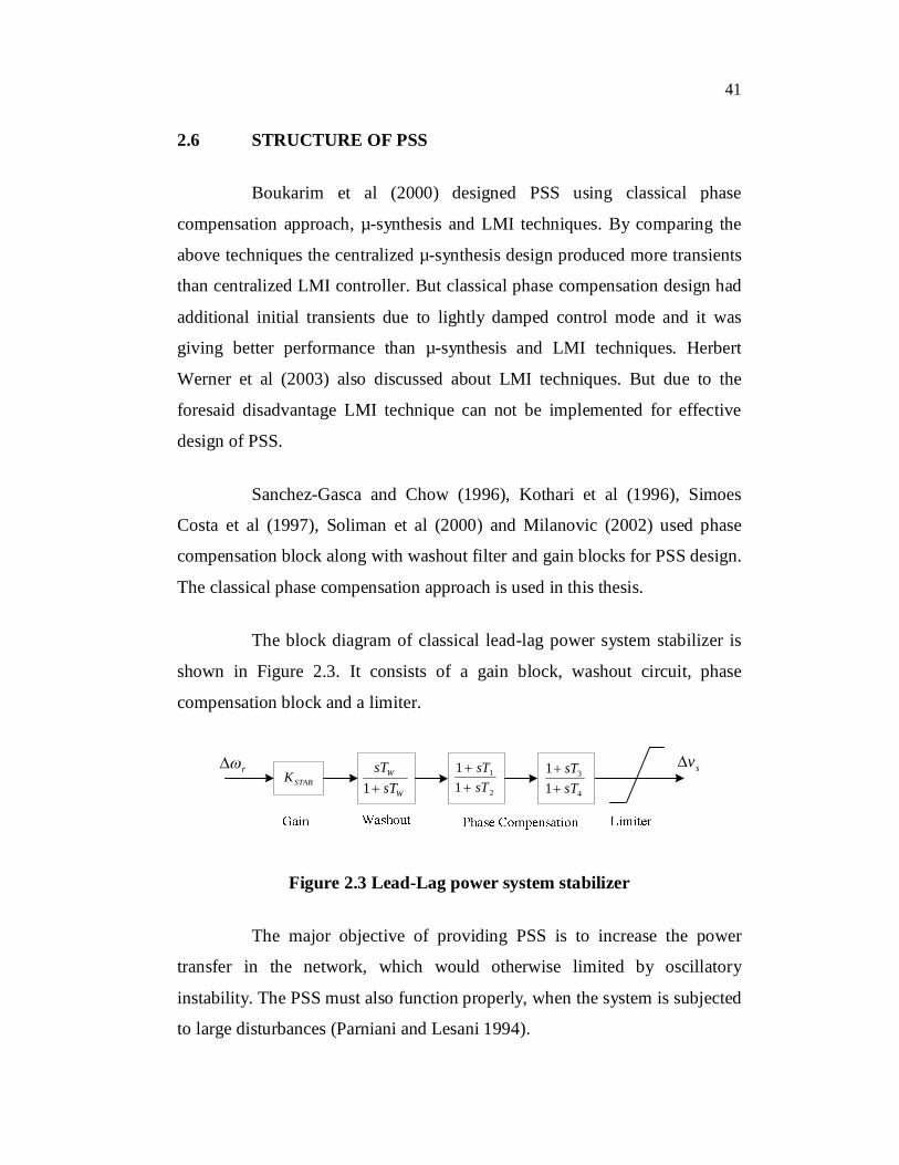
The block diagram of classical lead-lag power system stabilizer is
shown in Figure 2.3. It consists of a gain block, washout circuit, phase
compensation block and a limiter.
W
W
sTsT1STABK
r sv
2
1
11
sTsT
4
3
11
sTsT
Figure 2.3 Lead-Lag power system stabilizer
The major objective of providing PSS is to increase the power
transfer in the network, which would otherwise limited by oscillatory
instability. The PSS must also function properly, when the system is subjected
to large disturbances (Parniani and Lesani 1994).

42
2.6.1 Washout Block
The washout circuit is provided to eliminate steady-state bias in the
output of PSS which will modify the generator terminal voltage. The PSS is
expected to respond only to transient variations in the input signal (say rotor
speed) and not to the dc offsets in the signal. This is achieved by subtracting
from it the low frequency components of the signal obtained by passing the
signal through a low pass filter.
The washout circuit acts essentially as a high pass filter and it must
pass all frequencies that are of interest. If only the local modes are of interest,
the time constant WT can be chosen in the range of 1 to 2 seconds. However,
if inter area modes are also to be damped, then WT must be chosen in the
range of 10 to 20 seconds. The higher value of WT also improved the overall
terminal voltage response during system islanding conditions.
2.6.2 Phase Compensation Block
It provides the appropriate phase-lead characteristic to compensate
for the phase lag between the exciter input and the generator electrical (air-
gap) torque. The Figure 2.4 shows a single first-order block. In practice two
or more first-order blocks may be used to achieve the desired phase
compensation. In some cases, second-order blocks with complex roots have
been used.
Normally, the frequency range of interest is 0.1 to 3.0 Hz, and the
phase-lead network should provide compensation over this entire frequency
range. The phase characteristic to be compensated changes with system
conditions; therefore, a compromise is made and a characteristic acceptable
for different system conditions is selected. Generally some under
compensation is desirable so that the PSS, in addition to significantly

43
increasing the damping torque, results in a slight increase of the
synchronizing torque.
W
W
sTsT1
AK
2
1
11
sTsT
fdE
STABK
RsT11
refV
tE
2vr sv
1v
Figure 2.4 Thyristor excitation system with AVR and PSS
2.6.3 Gain Block
The stabilizer gain STABK determines the amount of damping
introduced by the PSS. Ideally, the gain should be set at a value
corresponding to maximum damping; however, it is often limited by other
considerations. The stabilizer gain STABK is chosen by examining the effect for
a wide range of values. Ideally, the stabilizer gain should be set at a value
corresponding to maximum damping. Gain is set to a value which results in
satisfactory damping of the critical system mode(s) without compromising the
stability of other modes, or transient stability, and which does not cause
excessive amplification of stabilizer input signal noise.
2.6.4 Stabilizer Output Limiter
In order to restrict the level of generator terminal voltage
fluctuation during transient conditions, limits are imposed on the PSS output.

44
The effect of the two limits is to allow maximum forcing capability while
maintaining the terminal voltage within the desired limits (Choi et al 2000).
The input for PSS is change in rotor speed and the output is control
voltage for the exciter.
2.7 STATE SPACE MODEL WITH PSS
Chow et al (2004) designed PSSs using root locus design,
frequency-response design and state space design. In root locus method a PI
controller was applied as a voltage regulator. As the proportional gain
increased, the closed loop step response became faster and steady state error
became smaller, but the oscillation due to the swing mode became less
damped. In frequency-response method, a phase lag-lead controller was used
to plot the compensated system frequency-response and to find the gain and
phase margins. In state space design full-state feedback laws and observers
derived from pole placement were used to design the voltage regulator and
PSS. Choi et al (2000), Hui Ni et al (2002), Guptha et al (2003, 2005) and
Elices et al (2004) used state space design for SMIB and multimachine
systems.
By considering the above drawbacks, the state space method is used
in this thesis.
2.7.1 Single Machine Connected to Infinite Bus (SMIB) System
A general system configuration for the synchronous machine
connected to the large system is shown in Figure 2.5. This general system is
used for the study of small signal stability study (Kundur 1994).

45
Figure 2.5 General configuration of a single machine power system
The general system configuration can be reduced to the Thevenin’s
equivalent circuit shown in Figure 2.6.
Figure 2.6 Equivalent circuit of a single machine power system
For any given system condition, the magnitude of the infinite bus
voltage EB remain constant when machine is perturbed.
The state space model of the system with PSS can be obtained as
follows by using field circuit dynamics and effects of AVR (Kundur 1994).
From block 4 of Figure 2.4, using perturbed values,
rSTABW
W KpT
pTv
12 (2.1a)
Hence,

46
221 v
TpKvp
WrSTAB
The expression for 2vp can be written in terms of the state
variables as follows,
213121121
21 v
TT
HaaaKvp
WmfdrSTAB
(2.1b)
mSTAB
fdr TH
Kvaaaavp 22555352512 (2.1c)
where
W
STAB
STABSTAB
TaaKa
aKaaKa1
551353
12521151
(2.2)
Since 2vp is not a function of 1v and 3v , 05654 aa . From
block 5 of Figure 2.4,
2
12 1
1pTpT
vvs (2.2a)
Hence
ss vT
vT
vpTTvp
22
22
2
1 11 (2.2b)
Substituting for 2vp , given by equation (2.1b), then
mSTAB
sfdrs TH
KTTvavavaaaavp
22
166265164636261
(2.3)

47
where
266
255
2
16553
2
163
522
16251
2
161
1
1
Ta
Ta
TTaa
TTa
aTTaa
TTa
(2.4)
From block 2 of Figure 2.4,
1vvKE sAfd
The field circuit equation, with PSS included becomes,
sfdfd vavaaap 361343332 (2.5)
where
Aadu
fd KL
Ra 0
36
(2.6)
The complete state space model including PSS can be written as,
s
fd
r
s
fd
r
vvv
aaaaaaaaa
aaaaaaa
aaaa
vvv
2
1
6665636261
55535251
444342
36343332
21
131211
2
1
000000
0000000000
(2.7)

48
where,
R
R
R
Aadu
fdA
adsfd
ads
fd
fd
adsfd
fd
D
Ta
TK
a
TK
a
a
KL
RKba
LmLL
LR
a
LmLR
a
faH
Ka
HKa
HKa
1
0
1
22
2
2
44
643
542
41
03234
20
33
10
32
0021
213
112
11
(2.8)
The K-constants can be written as follows (Kundur 1994).
2220
0222
0
06
1110
0111
0
05
32
324
33
323
00020022
0010011
1 mL
LmLnREe
nLnLmREeK
mLmLnREe
nLnLmREe
K
baK
abK
iLL
iLmiLnK
iLmiLnK
fdadsla
t
qaqsla
t
d
adslat
qaqsla
t
d
qfd
adsqadsaqdaqsad
qadsaqdaqsad
(2.9)

49
The above state space model is used in this thesis. The generator and transmission line data are given in Appendix 1.
2.7.2 Multimachine Power System
Analysis of practical power system involves the simultaneous
solution of equations representing the following:
Synchronous machines, the associated excitation system and
prime movers
Interconnecting transmission network
Static and dynamic (motor) load
Other devices such as HVDC converters, static VAR
compensators
The dynamics of the machine rotor circuits, excitation systems,
prime mover and other devices are represented by differential equations. The
result is that the complete system model consists of large number of ordinary
differential and algebraic equations (Hsu and Chen 1987, Tse G.T. Tso 1993).
Figure 2.7 Structure of the complete power system model

50
The general structure of complete model is shown in Figure 2.7.
The formulation of the state equations for small-signal analysis involves the
development of linearized equations about an operating point and elimination
of all variables other than the state variables (Lim and Elangovan 1985).
The multimachine system consists of extensive transmission
networks, loads, a variety of excitation systems and prime mover models,
HVDC links, and static var compensators (Rogers 2000, Simoes Costa et al
1997). Therefore the state equations are formulated by treating wide range of
devices.
The linearized model of each dynamic device is expressed in the
following form,
vBxAx iiii (2.10)
vYxCi iiii (2.11)
where
ix are the perturbed values of the individual device state variables
ii is the current injection into the network from the device
v is the vector of network bus voltage
In equations (2.10) and (2.11), iB and iY have non-zero elements
corresponding only to the terminal voltage of the device and any remote bus
voltages used to control the device. The current vector ii has two elements
corresponding to the real and imaginary components. Similarly, the voltage
vector v has two elements per bus associated with the device. Such state
equations for all the dynamic devices in the system may be combined into the
form,

51
vBxAx DD (2.12)
vYxCi DiD (2.13)
where x is the state vector of the complete system, and DA and DC are block
diagonal matrices composed of iA and iC associated with the individual
devices.
The interconnecting transmission network is represented
transmission network is represented by the node equation,
vYi N (2.14)
The elements of NY include the effects of nonlinear static loads.
Equating equation (2.13) associated with the devices and Equation (2.14)
associated with the network, then
vYvYxC NDD (2.15)
Hence,
xCYYv DDN1)( (2.16)
Substituting the above expression for v in equation (2.12) yields
the overall system state equation,
xCYYBxAx DDNDD1)( (2.17)
Axx
where the state matrix A of the complete system is given by,
DDNDD CYYBAA 1)( (2.18)

52
Figure 2.8 Single line diagram of 4-Machine, 10-Bus System
Figure 2.9 Single line diagram of 10-Machine, 39-Bus System

53
The single line diagram for 4-Machine, 10-Bus System and
10-Machine, 39-Bus System are shown in Figures 2.8 and 2.9 respectively.
The system data are given Appendix 2 and 3 respectively. Figure 10
represents the overall excitation system including PSS.
mTeT
mSqE
qd ii ,
fdEsV
tV
refV
Figure 2.10 Block diagram including excitation system and PSS
2.8 SELECTION OF PSS PARAMETERS
The overall excitation control system is designed so as to:
(i) Maximize the damping of the local plant mode as well as
inter-area mode oscillations without compromising the
stability of other modes;
(ii) Enhance system transient stability;
(iii) Not adversely affect system performance during major system
upsets which cause large frequency excursions; and
(iv) Minimize the consequences of excitation system malfunction
due to component failures.

54
The block diagram of the PSS used to achieve the desired
performance objectives is shown in Figure 2.2. The final stage in stabilizer
design involves the evaluation of its effect on the overall system performance.
First, the effect of the stabilizer on various modes of system oscillations is
determined over a wide range of system conditions by using a small-signal
stability program (Fleming et al 1981). This includes analysis of the effects of
the PSS on local plant modes, inter area modes, and control modes
(Arredondo 1997). In particular, it is important to ensure that there are no
adverse interactions with the controls of other nearby generating units and
devices.
The excitation control systems, designed and describe above,
provide effective decentralized controllers for the damping of
electromechanical oscillations in power systems (Fleming et al 1990).
Generally, the resulting design is much more robust that can be achieved
through use of other methods. The overall approach is used on
acknowledgement of the physical aspects of the power system stabilization
problem. The method used for establishing the characteristics of the PSS is
simple and required only the dynamic characteristics of the concerned
machines to be modeled in detail. Detailed analysis of the performance of the
power system is used to establish other parameters and to ensure adequacy of
the overall performance of the excitation control. The result is a control that
enhances the overall stability of the system under different operating
conditions (Gibbard 1991).
Since the PSS is tuned to increase the damping torque component for wide range of frequencies, it contributes to the damping of all system modes in which the respective generator has a high participation. This includes any new mode that may emerge as a result of changing system conditions. It is possible to satisfy the requirements for a wide range of system conditions with fixed parameters. Here, the effects of stabilizer on

55
various modes of oscillations are determined for a wide range of system conditions using eigen value programs. Also the effect of stabilizer was determined using discrete domain.
In this study single-machine-infinite-bus power system is considered initially. The supplementary stabilizing signal considered is one proportional to speed. A widely used conventional PSS is considered throughout the study.
The transfer function of PSS can be written as shown below from Figure 2.2,
4
3
2
1
11
11
1 sTsT
sTsT
sTsTKv
W
WSTAB
r
s
(2.19)
The first term is stabilizer gain. The second term is washout term with a time lag WT . The third term is a lead compensation to improve the
phase lag through the system. The numerical values of WT , 2T , 4T and system
data are given in Appendix 1. The remaining parameters namely STABK , 1T and
3T are assumed to be adjustable parameters.
The optimization problem is selection of these PSS parameters easily and accurately. The PSS parameters can be optimized by using any one of the following techniques.
(i) Artificial Neural networks (Chan and Hsu 1983, Chaturvedi et al 1999, Chaturvedi et al 2004a, Chaturvedi et al 2004b and Chaturvedi and Malik 2005, Guan et al 1996, He et al 1997, Liu et al 2003, Ramakrishna and Malik 2004, Ravi Segal et al 2000, Shamsollahi and Malik 1997, Shamsollahi and Malik 1997 1999, Yuan-Tih and Chao-Rong 1991, Zhang et al 1993 and 1995)

56
(ii) Fuzzy logic (El-Metwally et al 1996, Hariri and Malik 1996,
Hassan et al 1991, Hiyama and Sameshima 1991, Hoang and
Tomsovic 1996, Hosseinzadeh and Kalam 1999 a,
Hosseinzadeh and Kalam 1999 b, Lu et al 2000, Ortmeyer
and Hiyama 1995, Wen et al 1998.
(iii) Artificial neuro-fuzzy technique (Abido and Abdel-Magid
et al 1998, Linkens and Nyongesa 1995, Ruhua You et al
2003, You et al 2003)
(iv) Genetic algorithms (Abdel-Magid et al 1999, Abdel-Magid
and Abido 2003, Chiang 2005, Potts et al 1994, Taranto and
Falcao 1998)
(v) Evolutionary programming (Dechanupaprittha et al 2004,
Fogel 1995).
(vi) Ant colony optimization
(vii) H∞ Technique (Antal Soos and Malik et al 2002, Asgharian
1994, Chen et al 1995, Chuanjiang Zhu et al 2003,
Kwakernaak 1993, Yang 1997).
(viii) Differential evolution
(ix) Simulated annealing (Abido 2000).
(x) Tabu search (Abdel-Magid et al 2000, Abido and Abdel-
Magid 2000).
(xi) Particle swarm optimization (Abido 2002, Eberhart and Shi
2001, Esmin et al 2005, Gaing 2003).
In this thesis the PSS parameters are selected by solving the
objective function using Artificial Intelligence (AI) techniques like SA, PSO

57
and TS which were already handled by Abido (2000 and 2002) and
Abdel-Magid et al (2000) for various systems. For a given operating point, the
power system is linearized around the operating point, the eigen values of the
closed-loop system are computed, and the objective function is evaluated. It is
worth mentioning that only the system electromechanical modes are
incorporated in the objective function. The bounds on the parameters used in
the AI techniques are given in Appendixes 1,2 and 3.
2.9 CONCLUSION
In this chapter the importance and structure of lead-lag PSS was
studied. Chow et al (2004) implemented root locus method, frequency
response method and state space method. In root locus method, the steady
state error was small and the oscillation due to swing mode was less damped.
In frequency response method, the frequency response was plotted to find
gain and phase margin to analyze stability of the system. But in state space
design full state feedback laws and observers derived from pole placement
were used to design PSS. The state space design was better than root locus
and frequency response methods and is used in the present study. The
elements of state vector were obtained by using field circuit dynamics and
effects of AVR. The generalized model of multimachine system was obtained
by considering transmission networks, loads, variety of excitation systems,
prime mover models, HVDC links and static var compensators. The selection
of PSS parameters to maximize the damping of the local plant mode as well
as inter-area mode of oscillations was explained. The various optimization
techniques for tuning of PSS parameters were summarized.