Embed Size (px)
DESCRIPTION
Ótica de Fourier
Citation preview
Chapter 8 Analog Optical Information Processing
Weimin SunCollege of Science
Harbin Engineering University
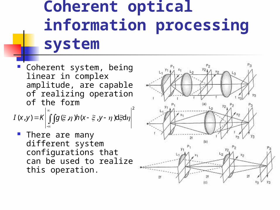
Coherent optical information processing system
Coherent system, being linear in complex amplitude, are capable of realizing operation of the form
There are many different system configurations that can be used to realize this operation.
2
-
dd),(),(),(
yxhgKyxI
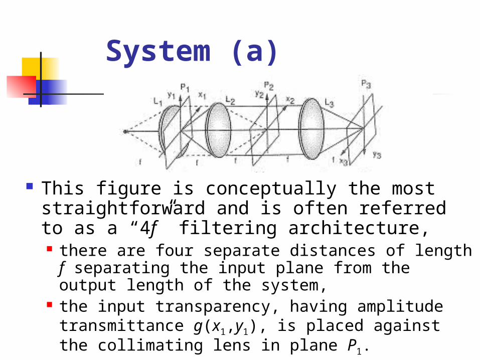
System (a)
This figure is conceptually the most straightforward and is often referred to as a “4f” filtering architecture, there are four separate distances of length f separating
the input plane from the output length of the system, the input transparency, having amplitude transmittance
g(x1,y1), is placed against the collimating lens in plane P1.
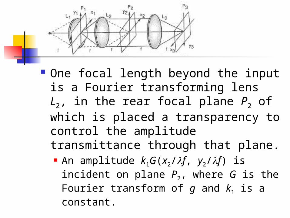
One focal length beyond the input is a Fourier transforming lens L2, in the rear focal plane P2 of which is placed a transparency to control the amplitude transmittance through that plane. An amplitude k1G(x2/f, y2/f) is incident on
plane P2, where G is the Fourier transform of g and k1 is a constant.
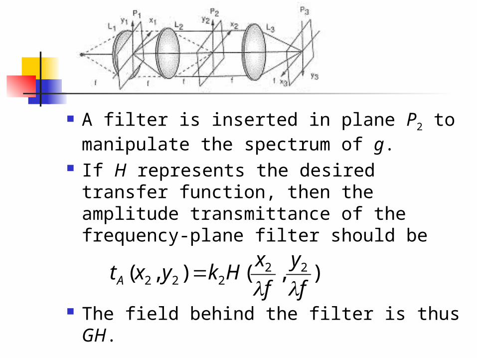
A filter is inserted in plane P2 to manipulate the spectrum of g.
If H represents the desired transfer function, then the amplitude transmittance of the frequency-plane filter should be
The field behind the filter is thus GH.
),(),( 22222 f
y
f
xHkyxtA
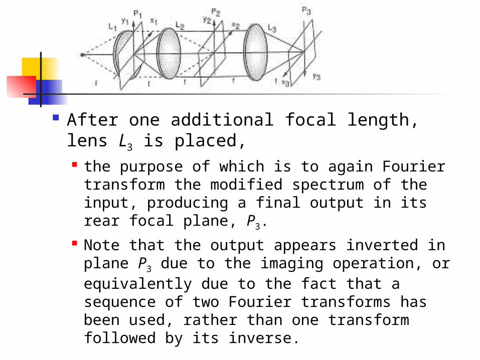
After one additional focal length, lens L3 is placed, the purpose of which is to again Fourier
transform the modified spectrum of the input, producing a final output in its rear focal plane, P3.
Note that the output appears inverted in plane P3 due to the imaging operation, or equivalently due to the fact that a sequence of two Fourier transforms has been used, rather than one transform followed by its inverse.
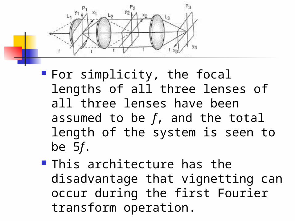
For simplicity, the focal lengths of all three lenses of all three lenses have been assumed to be f, and the total length of the system is seen to be 5f.
This architecture has the disadvantage that vignetting can occur during the first Fourier transform operation.
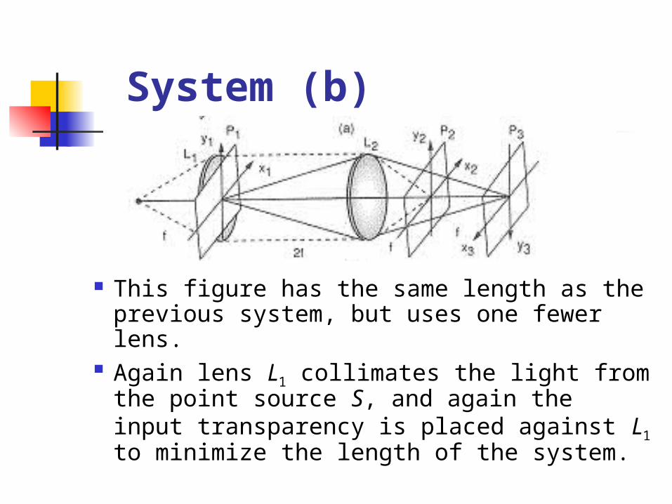
System (b)
This figure has the same length as the previous system, but uses one fewer lens.
Again lens L1 collimates the light from the point source S, and again the input transparency is placed against L1 to minimize the length of the system.
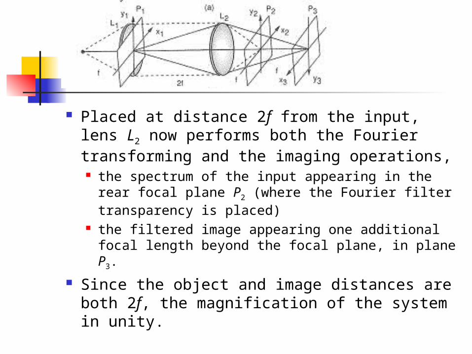
Placed at distance 2f from the input, lens L2 now performs both the Fourier transforming and the imaging operations, the spectrum of the input appearing in the rear focal
plane P2 (where the Fourier filter transparency is placed)
the filtered image appearing one additional focal length beyond the focal plane, in plane P3.
Since the object and image distances are both 2f, the magnification of the system in unity.
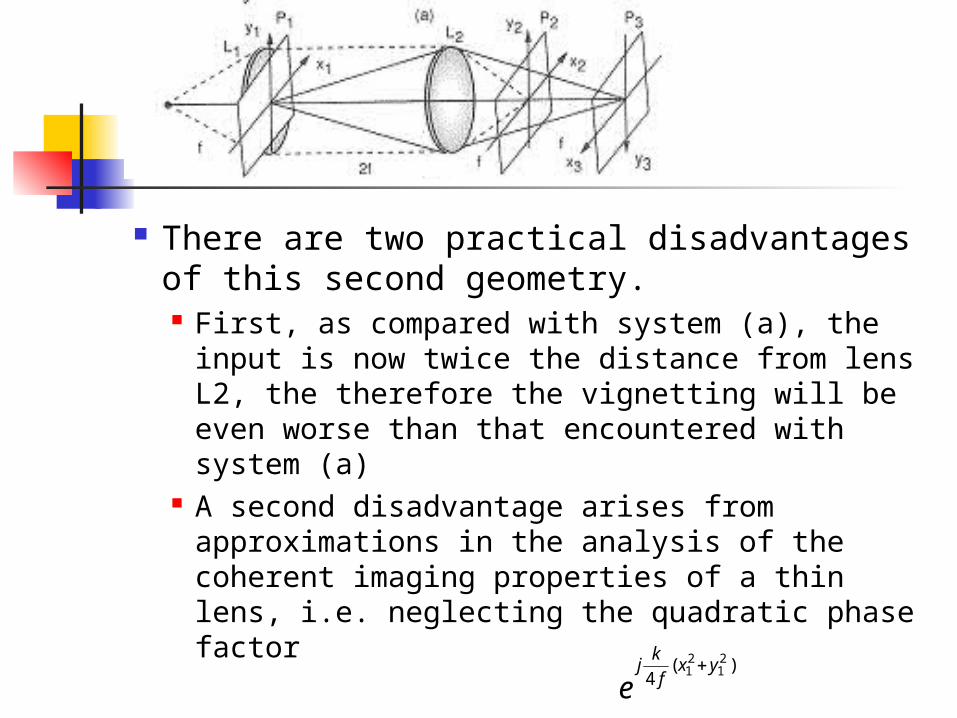
There are two practical disadvantages of this second geometry. First, as compared with system (a), the input is
now twice the distance from lens L2, the therefore the vignetting will be even worse than that encountered with system (a)
A second disadvantage arises from approximations in the analysis of the coherent imaging properties of a thin lens, i.e. neglecting the quadratic phase factor )(
421
21 yx
f
kj
e
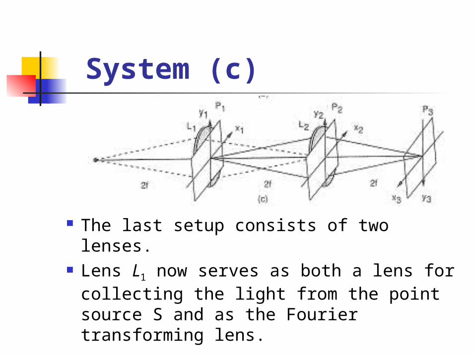
System (c)
The last setup consists of two lenses. Lens L1 now serves as both a lens for
collecting the light from the point source S and as the Fourier transforming lens.
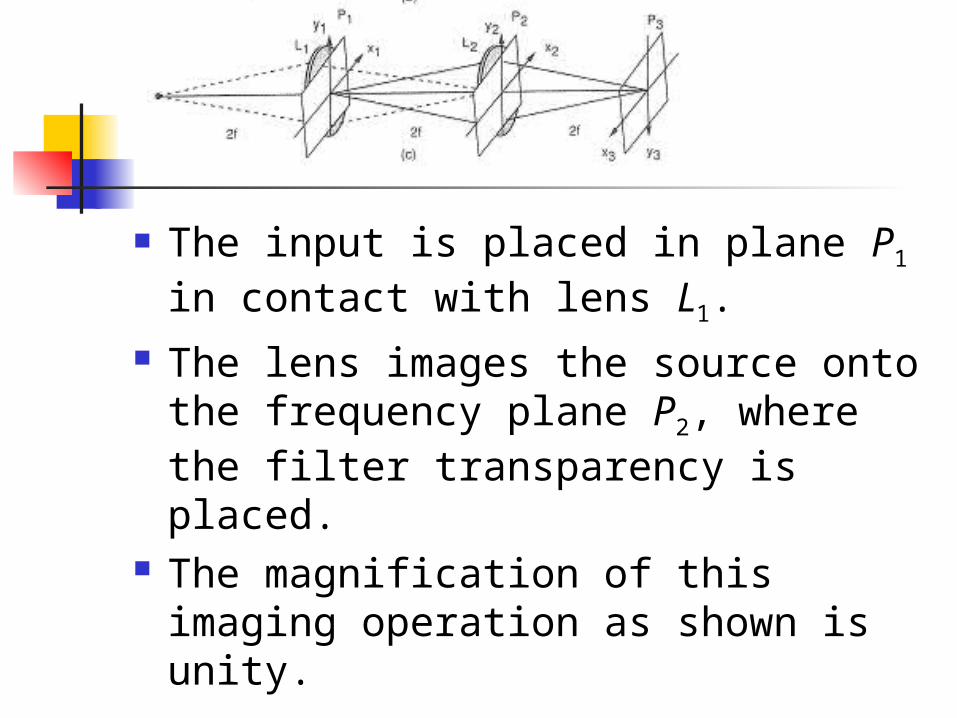
The input is placed in plane P1 in contact with lens L1.
The lens images the source onto the frequency plane P2, where the filter transparency is placed.
The magnification of this imaging operation as shown is unity.
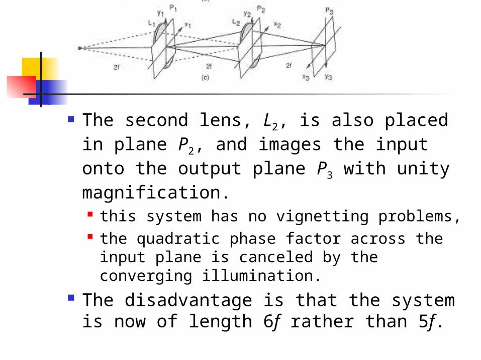
The second lens, L2, is also placed in plane P2, and images the input onto the output plane P3 with unity magnification. this system has no vignetting problems, the quadratic phase factor across the input plane
is canceled by the converging illumination. The disadvantage is that the system is now
of length 6f rather than 5f.
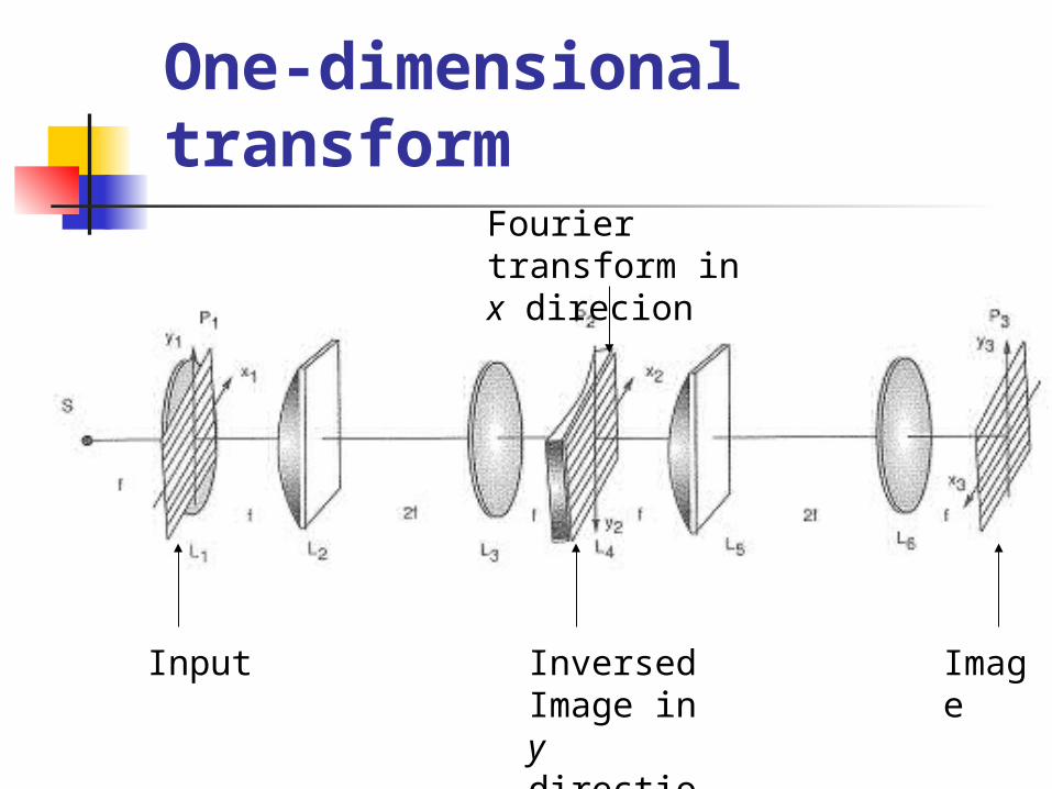
One-dimensional transform
Input Inversed Image in y direction
Image
Fourier transform in x direcion
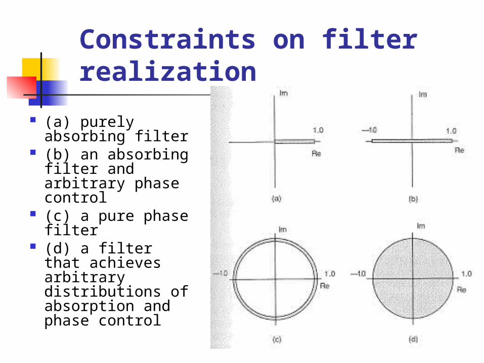
Constraints on filter realization
(a) purely absorbing filter
(b) an absorbing filter and arbitrary phase control
(c) a pure phase filter
(d) a filter that achieves arbitrary distributions of absorption and phase control
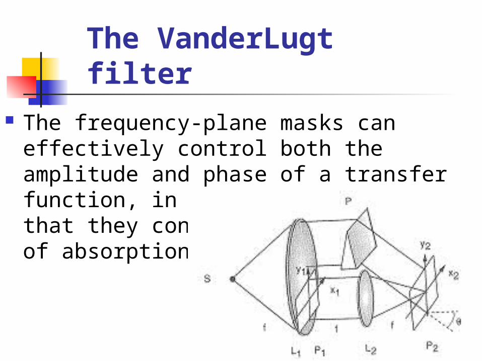
The VanderLugt filter
The frequency-plane masks can effectively control both the amplitude and phase of a transfer function, in spite of the fact that they consist only of patterns of absorption.
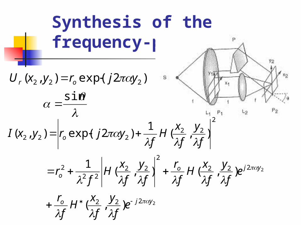
Synthesis of the frequency-plane mask
)2exp(),( 222 yjryxU or
sin
2
2
222
222
2
2222
2
2
22222
),(
),(),(1
),(1
)2exp(),(
yjo
yjoo
o
ef
y
f
xH
f
r
ef
y
f
xH
f
r
f
y
f
xH
fr
f
y
f
xH
fyjryxI
),(2222
22
),(),( f
y
f
xj
ef
y
f
xA
f
y
f
xH
)],(2cos[),(2
),(1
),(
222
22
22222
222
f
y
f
xy
f
y
f
xA
f
r
f
y
f
xA
fryxI
o
o
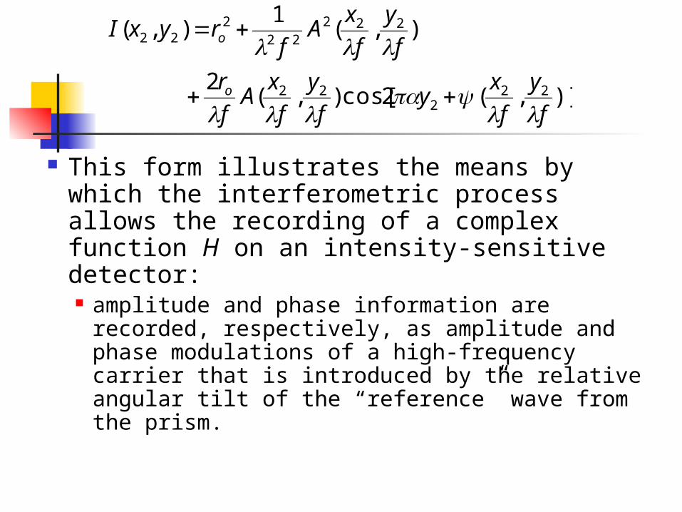
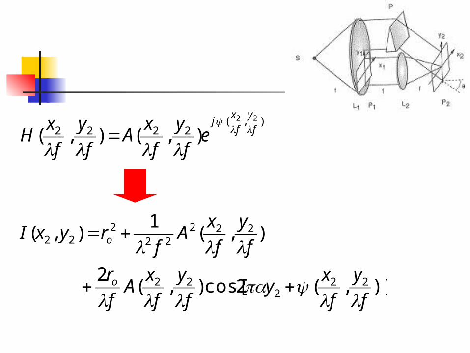
This form illustrates the means by which the interferometric process allows the recording of a complex function H on an intensity-sensitive detector: amplitude and phase information are recorded,
respectively, as amplitude and phase modulations of a high-frequency carrier that is introduced by the relative angular tilt of the “reference” wave from the prism.
)],(2cos[),(2
),(1
),(
222
22
22222
222
f
y
f
xy
f
y
f
xA
f
r
f
y
f
xA
fryxI
o
o
In practice, optical spatial filters are generally passive types, for which the physically realizable conditions are imposed by
1),( 22 f
y
f
xA
2),(0 22 f
y
f
x
)],(2cos[),(2
),(1
),(
222
22
22222
222
f
y
f
xy
f
y
f
xA
f
r
f
y
f
xA
fryxI
o
o
Other ways
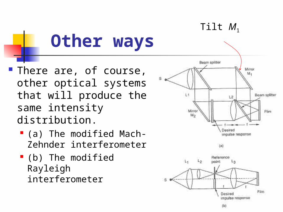
There are, of course, other optical systems that will produce the same intensity distribution. (a) The modified Mach-
Zehnder interferometer (b) The modified
Rayleigh interferometer
Tilt M1
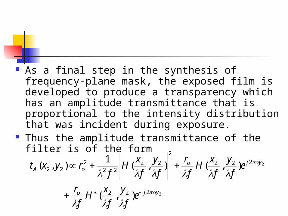
As a final step in the synthesis of frequency-plane mask, the exposed film is developed to produce a transparency which has an amplitude transmittance that is proportional to the intensity distribution that was incident during exposure.
Thus the amplitude transmittance of the filter is of the form
2
2
222
222
2
2222
222
),(
),(),(1
),(
yjo
yjooA
ef
y
f
xH
f
r
ef
y
f
xH
f
r
f
y
f
xH
fryxt
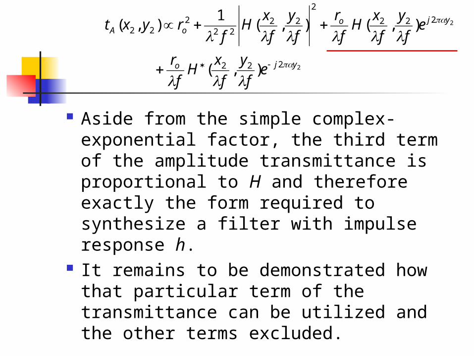
Aside from the simple complex-exponential factor, the third term of the amplitude transmittance is proportional to H and therefore exactly the form required to synthesize a filter with impulse response h.
It remains to be demonstrated how that particular term of the transmittance can be utilized and the other terms excluded.
2
2
222
222
2
2222
222
),(
),(),(1
),(
yjo
yjooA
ef
y
f
xH
f
r
ef
y
f
xH
f
r
f
y
f
xH
fryxt
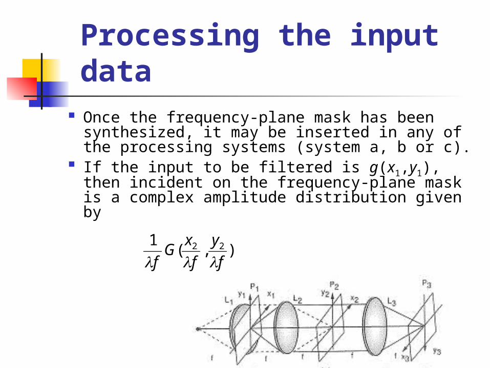
Processing the input data Once the frequency-plane mask has been
synthesized, it may be inserted in any of the processing systems (system a, b or c).
If the input to be filtered is g(x1,y1), then incident on the frequency-plane mask is a complex amplitude distribution given by
),(1 22
f
y
f
xG
f
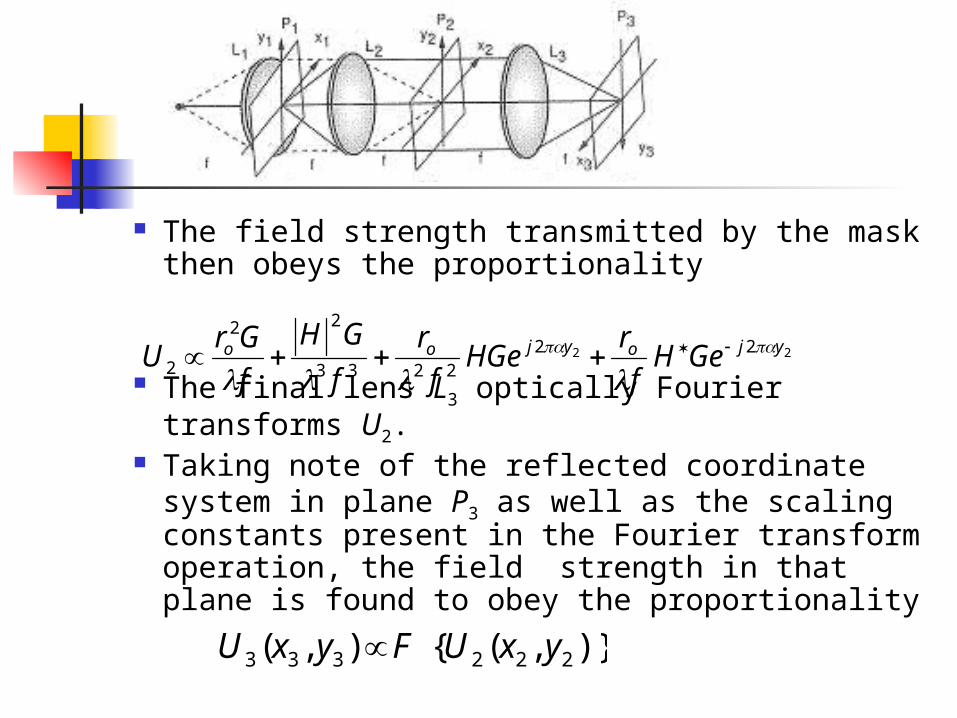
The field strength transmitted by the mask then obeys the proportionality
The final lens L3 optically Fourier transforms U2. Taking note of the reflected coordinate system in
plane P3 as well as the scaling constants present in the Fourier transform operation, the field strength in that plane is found to obey the proportionality
22 222233
22
2yjoyjoo GeH
f
rHGe
f
r
f
GH
f
GrU
)},({),( 222333 yxUyxU F
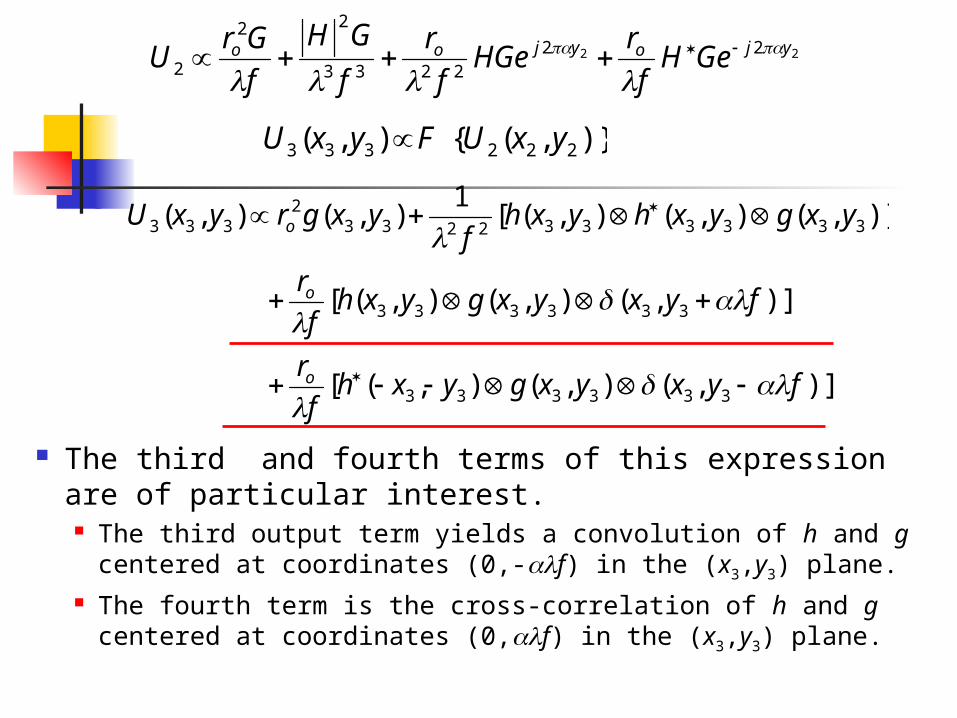
The third and fourth terms of this expression are of particular interest. The third output term yields a convolution of h and g centered at
coordinates (0,-f) in the (x3,y3) plane. The fourth term is the cross-correlation of h and g centered at
coordinates (0,f) in the (x3,y3) plane.
)],(),(),([
)],(),(),([
)],(),(),([1
),(),(
333333
333333
33333322332
333
fyxyxgyxhf
r
fyxyxgyxhf
r
yxgyxhyxhf
yxgryxU
o
o
o
22 222233
22
2yjoyjoo GeH
f
rHGe
f
r
f
GH
f
GrU
)},({),( 222333 yxUyxU F
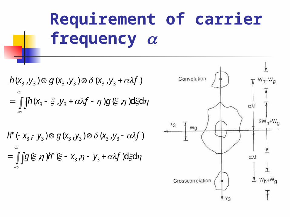
Requirement of carrier frequency
-
33
333333
dd),(),(
),(),(),(
gfyxh
fyxyxgyxh
-
33
333333
dd),(),(
),(),(),(
fyxhg
fyxyxgyxh
Advantages of the VanderLugt filter
The use of a VanderLugt filter removes the two most serious limitations to conventional coherent optical processors. When a specified impulse response is desired, the task of
finding the associated transfer function is eliminated; the impulse response is Fourier transformed optically by the system that synthesizes the frequency-plane mask.
The generally complicated complex-valued transfer function is synthesized with a single absorbing mask; the phase transmittance through the frequency plane need no longer be controlled in a complicated manner.
The absorbing mask is simply immersed in a liquid gate to eliminate all relative phase shifts.