Embed Size (px)
Citation preview

REGISTRO BRASILEIRO Rules for the Construction and Classification of Ships OIL TANKERS - Title 32
DE NAVIOS E AERONAVES Identified by their Missions – Part II NAVAL ARCHITECTURE - Section 1
RGMM20EN CHAPTER - Index
1-1 RULES 2020
PART II RULES FOR THE CONSTRUCTION
AND CLASSIFICATION OF SHIPS
IDENTIFIED BY THEIR MISSIONS
TITLE 32 OIL TANKERS
SECTION 1 NAVAL ARCHITECTURE
CHAPTERS
A APPROACH
B DOCUMENTS, REGULATIONS AND STAND-
ARDS
C ENVIROMENT OF THE NAVIGATION
See Part II, Title 11, Section 1
D ACTIVITIES/SERVICES
See Part II, Title 11, Section 1
E CONFIGURATIONS
F HULL DIMENSIONS AND LINES
See Part II, Title 11, Section 1
G CAPACITIES AND COMPARTMENTING
H CONDITIONS OF LOADING, BUOYANCY
AND STABILITY
I PERFORMANCE OF PROPULSION
See Part II, Title 11, Section 1
T INSPECTIONS AND TESTS
See Part II, Title 11, Section 1

REGISTRO BRASILEIRO Rules for the Construction and Classification of Ships OIL TANKERS - Title 32
DE NAVIOS E AERONAVES Identified by their Missions – Part II NAVAL ARCHITECTURE - Section 1
RGMM20EN CHAPTER - Index
1-2 RULES 2020

REGISTRO BRASILEIRO Rules for the Construction and Classification of Ships OIL TANKERS - Title 32
DE NAVIOS E AERONAVES Identified by their Missions – Part II NAVAL ARCHITECTURE - Section 1
RGMM20EN CHAPTER - Topics
1-3 RULES 2020
CONTENTS
CHAPTER A ................................................................... 5
APPROACH .................................................................... 5
A1. APPLICATION ................................................. 5 100. Cargo types .................................................... 5
A2. DEFINITIONS .................................................. 6 100. Terms ............................................................. 6
A3. BASIC PRINCIPLES ......................................... 7 100. Risk of fire...................................................... 7 200. Risks of pollution from the cargo .................... 8 300. Spaces adjacent to tanks ................................. 8
CHAPTER B ................................................................... 9
DOCUMENTS, REGULATIONS AND STANDARDS . 9
B1. DOCUMENTS TO THE RBNA ......................... 9 100. Documents of reference .................................. 9 200. Documents for approval ................................. 9 300. Documents for construction ............................ 9
B2. STATUTORY REGULATIONS ........................ 9 100. National RBNA for oil carriers with GT < 500
9 200. Regulation for ships with GT ≥ 500................. 9
CHAPTER E ................................................................. 10
CONFIGURATIONS .................................................... 10
E2. CARGO AREA OF TANKERS ........................ 10 100. Application................................................... 10 200. Separation of cargo oil tanks ........................ 10 300. Lighting enclosures and ventilation
arrangement ............................................................ 11 400. Cargo tank venting ....................................... 11 500. Vent outlets for cargo handling and ballasting
11 600. Ventilation ................................................... 11
E3. GENERAL ARRANGEMENT OF THE SHIP
REGARDING FIRE PREVENTION AND CREW
SAFETY ..................................................................... 11 100. Application................................................... 11 200. Forward and aft peak tanks .......................... 12 300. Cargo pump room ........................................ 12 400. Machinery spaces ......................................... 12 500. Accommodation spaces, service spaces and
control stations ........................................................ 12 E4. ACCESSES AND OPENINGS ......................... 13
200. Access and openings to accommodation spaces,
service spaces, control stations and machinery spaces
13 300. Access to spaces in the cargo area ................ 14 400. Access to the pipe tunnels ............................. 14 500. Other accesses ............................................. 15 600. Cofferdams................................................... 15 700. Compartments in hazardous zones ................ 15 800. Openings and passages in the bulkheads for
piping, shafts and electric cables.............................. 15 E5. SEGREGATION OF OIL AND WATER
BALLAST .................................................................. 15 100. Requirements for segregation of oil and water
ballast 15
CHAPTER G ................................................................. 17
CAPACITIES AND COMPARTMENTING................ 17
G1. SUBDIVISION OF THE HULL ....................... 17 100. Main transverse bulkheads ........................... 17 200. Double-hull– protection of cargo tank in the
event of stranding, collision or leak .......................... 17 G2. OIL TANKERS WITH DEADWEGHT ≥ 5000 T
17 100. General ........................................................ 17 200. Wing tanks or spaces .................................... 17 300. Tanks or spaces of the double bottom............ 17
G3. OIL TANKERS WITH DEADWEGHT < 5000 T
18 100. General ........................................................ 18 200. Size limitation of tanks to ships with 5000 T
DWT 18 300. IACS Unified Interpretation MPC87 ............. 19
CHAPTER H ................................................................. 20
CONDITIONS OF LOADING, BUOYANCY AND
STABILITY .................................................................. 20
H5. STABILITY .................................................... 20 100. Intact Stability .............................................. 20
H6. DAMAGE STABILITY ................................... 21 200. Permeability ................................................. 23 300. Survival requirements ................................... 23
H7. INTACT STABILITY OF TANKERS WITH GT
≥ 500 DURING LIQUID TRANSFER OPERATIONS . 24 100. Approach ..................................................... 24 200. Stability criteria ........................................... 24 300. Loading conditions ....................................... 24

REGISTRO BRASILEIRO Rules for the Construction and Classification of Ships OIL TANKERS - Title 32
DE NAVIOS E AERONAVES Identified by their Missions – Part II NAVAL ARCHITECTURE - Section 1
RGMM20EN CHAPTER - Topics
1-4 RULES 2020
REGISTRO BRASILEIRO Rules for the Construction and Classification of Ships OIL TANKERS - Title 32
DE NAVIOS E AERONAVES Identified by their Missions – Part II NAVAL ARCHITECTURE - Section 1
RGMM20EN CHAPTER - A
1-5 RULES 2020
CHAPTER A
APPROACH
CHPATER CONTENTS
A1. APPLICATION
A2. DEFINITIONS
A3. BASIC PRINCIPLES
A1. APPLICATION
100. Cargo types
101. The requirements of the present Part II, Title 32, apply
to all ships destined to the transportation of IMDG Class 3
products, including the products listed on IBC Chapters 17
and 18 tables which are allowed to be transported in oil
tankers.
a. The present Title 32 applies to oil tankers having length
under 150 metres.
b. For oil tankers having length equal to or over 150 me-
ters, the requirements of CSR-H as amended apply.
TABLE T.A1.101.1. FLAMMABLE LIQUIDS CLASS 3,
CATEGORIES
Category Flash Point
f (oC)
Vapour pressure
at 50 oC
p (bar)
Obs
K3 60 f 100 patm -
K2 21 f 60 patm -
K1n f 21 p 1,1 -
Guidance
Definition of some flammable products
Jet A: is a kerosene grade fuel, normally available in the
USA. It has the same flash point as Jet A-1 but a higher
freeze point maximum (-40°C). It is supplied against the
ASTM D1655 (Jet A) specification. Suitable extinguishing
media: Alcohol-resistant foam. Carbon dioxide (CO2). Dry
chemical. Unsuitable extinguishing media: high volume wa-
ter jet. Special protective equipment for fire-fighters: wear
self-contained breathing apparatus for fire fighting if neces-
sary.
Jet A-1: is a kerosene grade of fuel suitable for most turbine
aircraft. It has a flash point minimum of 38ºC (100°F)
closed cup and a freeze point maximum of -47º C. The main
specifications for Jet A-1 grade are the UK specification
DEF STAN 91-91 (Jet A-1) Nato code F-35, (formerly
DERD 2494) and the ASTM specification D1655 (Jet A-1).
This is the jet fuel supplied by Petrobras (QAV-1). Suitable
extinguishing media: alcohol resistant foam, chemical pow-der, carbon dioxide (CO2), water fog. Unsuitable extin-
guishing media: solid water jet. Special protective equip-
ment for fire-fighters: full firefighting clothes with self-
breathing apparatus (SCBA). Vapour pressure: 0,480
mmHg a 20°C (0,06 bar).
Jet B: is a distillate covering the naphtha and kerosene
fractions. It can be used as an alternative to Jet A-1 but be-
cause it is more difficult to handle (higher flammability),
there is only significant demand in very cold climates where
its better cold weather performance is important. ASTM
have a specification for Jet B but in Canada it is supplied against the Canadian Specification CAN/CGSB 3.23
JP-4: used to be the primary jet fuel for the USAF but was
phased out in the 1990s because of safety problems. A few
air forces around the world still use it but there is very little
production. JP-4 is the military equivalent of Jet B with the
addition of corrosion inhibitor and anti-icing additives; it
meets the requirements of the U.S. Military Specification
MIL-PRF-5624S Grade JP-4. The UK Military specification
for this grade is DEF STAN 91-88 AVTAG/FSII (formerly
DERD 2454),where FSII stands for Fuel Systems Icing In-hibitor. NATO Code F-40.
JP-5: is a high flash point kerosene meeting the require-
ments of the U.S. Military Specification MIL-PRF-5624S
Grade JP-5. The UK Military specification for this grade is
DEF STAN 91-86 AVCAT/FSII (formerly DERD 2452). This
is primarily jet fuel for use in aircraft carriers. NATO Code
F-44.
JP-8 is the military equivalent of Jet A-1: with the addition
of corrosion inhibitor and anti-icing additives; it meets the
requirements of the U.S. Military Specification MIL-T-83188D. It is the dominant military jet fuel grade for NATO
air forces. The UK also have a specification for this grade
namely DEF STAN 91-87 AVTUR/FSII (formerly DERD
2453). NATO Code F-34.
White spirit (UK) or mineral spirits (US), also known as
mineral turpentine, turpentine substitute, petroleum spirits,
solvent naphtha (petroleum) or Stoddard solvent, is a paraf-
fin-derived clear, transparent liquid which is a common or-
ganic solvent used in painting and decorating. Flammable,
Class 3, Auto-Ignition Temperature: 245°C (473°F), Flash Point closed cup = 38°C (100.4°F), Flammable Limits: low-
er: 1%
Ethanol/Ethanol hydrated fuel EHC: UN number 1170,
IMDG Class 3 Category 2 (highly flammable product), flash
point 15°C (closed cup), vapour pressure 5,8 kPa at 20°C,
used as fuel for gasoline engines. Suitable extinguishing
media: alcohol resistant foam, chemical powder, carbon
dioxide (CO2), water fog. Unsuitable extinguishing media:
solid water jet is not to be used for fires on this product.
Containers and tanks involved in a fire shall be cooled by means of water fog. Hazards: highly flammable, may ex-
plode when contained in recipients subject to heat and con-
fined spaces, toxic fumes. Special protective equipment for

REGISTRO BRASILEIRO Rules for the Construction and Classification of Ships OIL TANKERS - Title 32
DE NAVIOS E AERONAVES Identified by their Missions – Part II NAVAL ARCHITECTURE - Section 1
RGMM20EN CHAPTER - A
1-6 RULES 2020
fire-fighters: full firefighting clothes with self breathing ap-
paratus (SCBA).
End of guidance
A2. DEFINITIONS
100. Terms
101. In addition to the terms defined in Part II, Title 11,
Section 1, Topic A2.100., the following terms are defined in
this Section:
102. Cargo Area: the cargo area is a part of the ship that
contains cargo tanks as well as slop tanks, cargo pump
rooms including pump rooms, cofferdams, ballast or void
spaces adjacent to cargo tanks or slop tanks as well as deck
areas throughout the entire length and breadth of the part of
the ship above these spaces.
a. The cargo area above the deck is defined as follows:
a.1. Forward: The area covered by a plane starting at the forward bulkhead of the foremost cofferdam
and running aft at an angle of 45 degrees up to a
height of 3 meters above the deck, limited at the
sides by the side shell. In case there is no cofferdam
between the foremost cargo tank and the fore peak
tank, the plane will start from the bow and encom-
pass the deck area of the fore peak tank.
a.2. Aft: The area covered by a plane starting at the af-
ter bulkhead of the cofferdam between the Engine
Room and the aft cargo tank running forward at an
angle of 45 degrees up to 3 meters above the deck, limited at the sides by the side shell. The cargo
pump room may be accepted as a cofferdam. In
case there is no cofferdam between the aftermost
cargo tank and the Engine Room, the plane will
start from the forward bulkhead of the Engine
Room;
a.3. In case of a non-propelled oil tanker barge, the
plane will start from the after bulkhead of the cof-
ferdam (or pump room) between the aftermost car-
go tank and the aft peak tank running forward at an angle of 45 degrees up to 3 metres above the deck,
limited at the sides by the side shell; however, in
case there is no cofferdam between the aftermost
cargo tank and the aft peak tank, the plane will start
from the stern and encompass the deck area of the
aft peak tank.
b. At air vents, inlets and outlets:
b.1. Spheres with the following radius, counted from
the following openings:
i. 1 meter from ventilation openings of coffer-
dams;
ii. 1 metre from pump room entrances;
iii. 2 metres from vents of cargo tanks;
iv. 3 metres from ventilation openings of cargo
pump room space;
v. Transverse planes forming 45º angle forward
with the deck, from the extreme aft bulkhead of
cofferdam or pump room, and forming an angle
of 45º afterward with the deck, from the ex-
treme forward bulkhead of cofferdam or the
forward pump room.
b.2. When independent tanks are installed in hold spaces,
the cofferdams, ballast or void spaces at the after end
of the aftermost hold space, or at the forward end of
the forward most hold space, are excluded from the
cargo area.
103. Cargo pump space or pump room: designates a
compartment located in the cargo area, containing pumps
and their accessories operating with products covered by
this Title.
104. Cargo service spaces: designate compartments locat-
ed in the cargo area used as workshops, store rooms, of
more than 2 m2 of area, used for cargo handling equipment.
105. Clean ballast means the ballast in a tank which since
oil was last carried therein, has been cleaned so that the ef-
fluent therefrom if it were discharged from a ship which is
stationary into clean calm water on a clear day would not
produce visible traces of oil on the surface of the water or on
adjoining shorelines or cause a sludge or emulsion to be de-
posited beneath the surface of the water or upon adjoining shorelines. If the ballast is discharged through an approved
oil discharge monitoring and control system evidence based
on such a system to the effect that the oil content of the ef-
fluent did not exceed 15 parts per million shall be determi-
native that the ballast was clean, notwithstanding the pres-
ence of visible traces.
106. Cofferdam: means the spaces between two bulkheads
or decks primarily designed as a safeguard against leakage
of oil from one compartment to another.
107. Control station: designates compartments into which
the ship's radio equipment, navigation equipment, the emer-
gency source of power, or equipment of fire control is locat-
ed. The special fire control equipment (which may be locat-
ed in the cargo area) is not included in this definition.
108. Crude oil: means any liquid mixture of hydrocarbons
occurring naturally on Earth, whether or not treated to ren-
der it suitable for carriage, and covers:
a. crude oil from which may have been set aside certain parts distilled; and

REGISTRO BRASILEIRO Rules for the Construction and Classification of Ships OIL TANKERS - Title 32
DE NAVIOS E AERONAVES Identified by their Missions – Part II NAVAL ARCHITECTURE - Section 1
RGMM20EN CHAPTER - A
1-7 RULES 2020
b. crude oil to which may have been added certain distilled
parts.
109. Crude oil tanker: means an oil tanker engaged in the
trade of carrying crude oil.
110. Flash point: means the temperature in Celsius in
which a product will vaporize to form an ignitable mixture.
The values provided in this Title of the Rules are obtained
from "closed up test".
111. Fuel oil: means any oil used as fuel for ignition of the
propulsion and auxiliary machinery of the ship in which the
oil is being carried.
112. Hazardous area: area in which an explosive gas at-
mosphere is or may be expected to be present, in quantities
such as to require special precautions for the construction,
installation and use of electrical apparatus.
a. Zone 0: area in which an explosive gas atmosphere is
present continuously or is present for long periods;
b. Zone 1: area in which an explosive gas atmosphere is
likely to occur in normal operation;
c. Zone 2: area in which an explosive gas atmosphere is
not likely to occur in normal operation and, if it does oc-
cur, is likely to do so only infrequently and will exist for
a short period only;
d. Extended hazardous area: area in which an explosive
atmosphere is not likely to occur in normal operation
and, if it does occur, is likely to do so only infrequently
and will exist for a short period only (and comparable
with zone 2 as defined in IEC 60092-502).
113. Independent: means a line of pipe or ventilation sys-
tem, for example, which is not in any way connected with
any other system and where there are no provisions availa-
ble for potential connection with other systems.
114. Machinery space: See Part II, Title 11, Section 1,
Chapter A2.
115. Machinery space class A: See Part II, Title 11, Sec-
tion 1, Chapter A2.
116. MARPOL: means the International Convention for
the Prevention of Pollution from Ships, 1973, as modified
by the Protocol of 1978 (as amended).
117. Non-sparking fan: is considered as non-sparking if in
either normal or abnormal conditions it is unlikely to pro-
duce sparks. See Part II, Title 32, Section 6, Topic F6.300.
118. Oil tanker means a ship built or adapted primarily to
carry mainly bulk oil in its cargo spaces, and includes ore-
oil ships, any "NLS tanker", as defined in annex II to the MARPOL Convention, and any "gas carrier vessel", as de-
fined in regulation 3.20 of Chapter II-1 of SOLAS 74 (as
amended), when carrying a load, or a part of the loadbulk
oil.
119. Oily mixture: means a mixture with any oil content.
120. Ore-bulk-oil tanker: means a ship engaged in the
trade of carrying oil or solid cargoes in bulk.
121. Products tanker means an oil tanker engaged in the
trade of carrying oil other than crude oil.
122. Segregated ballast: Segregated ballast means the bal-
last water introduced into a tank which is completely sepa-
rated from the cargo oil and fuel oil system and which is permanently allocated to the carriage of ballast or to the car-
riage of ballast or cargoes other than oil or noxious sub-
stances as defined in MARPOL Annex II.
123. Slop tank: means a tank specifically designated for
the collection of tank draining, tank washings and other oily
mixtures.
125. Sludge (oil residues): means the residual waste oil
products generated during the normal operation of a ship,
such as those resulting from the purification of fuel or lubri-cating oil for main or auxiliary machinery, separated waste
oil from oil filtering equipment, waste oil collected in drip
trays, and waste hydraulic and lubricating oils.
126. Sludge tank (oil residue tank): means a tank which
holds oil residue (sludge) from which sludge may be dis-
posed directly through the standard discharge connection or
any other approved means of disposal.
127. Void: An enclosed empty space in a ship external to a
cargo tank other than a cargo hold, ballast compartment, fuel
oil tank, cargo pump room, pump room or any other space commonly used by the crew.
A3. BASIC PRINCIPLES
100. Risk of fire
101. See Part II, Title 11, Section 3, Chapter E2 of these
Rules for general requirements , and in the Part II, Title 32,
Section 3, Subchapter E2 for additional requirements for oil tankers. The recommendations of the SOLAS 74/78 Con-
vention, as amended, having as objective:
a. Segregate cargo oil from its ignition sources;
b. Reduce the flammability of cargo oil vapor and mix-
tures;
c. Observe the safety of electrical equipment in hazardous
areas;
d. Provide effective means of extinguishing fires which
may break out.

REGISTRO BRASILEIRO Rules for the Construction and Classification of Ships OIL TANKERS - Title 32
DE NAVIOS E AERONAVES Identified by their Missions – Part II NAVAL ARCHITECTURE - Section 1
RGMM20EN CHAPTER - A
1-8 RULES 2020
200. Risks of pollution from the cargo
201. These requirements follow the recommendations of
Annex I of MARPOL, aiming to:
a. segregate the ballast and the ballast pipes from contami-
nation by the cargo in tanks or pipe lines;
b. provide effective means of tank cleaning;
c. provide means of processing and discharging of contam-
inated water tanks.
300. Spaces adjacent to tanks
301. Tanks and spaces separated from the cargo tanks by a
single deck or bulkhead are at risk of being contaminated by
vapour or cargo due to possible failures in their partition
surfaces, as well as the pipes serving such spaces that, as
such, are considered risk zones. These pipes shall not pene-
trate into the machinery spaces.
302. The fuel oil tanks of the ship's machinery and their
pipes are excluded from these requirements.

REGISTRO BRASILEIRO Rules for the Construction and Classification of Ships OIL TANKERS - Title 32
DE NAVIOS E AERONAVES Identified by their Missions – Part II NAVAL ARCHITECTURE - Section 1
RGMM20EN CHAPTER - B
1-9 RULES 2020
CHAPTER B
DOCUMENTS, REGULATIONS AND STANDARDS
CHAPTER CONTENTS
B1. DOCUMENTS TO RBNA
B2. STATUTORY REGULATIONS
B3. TECHNICAL STANDARDS
See Part II, Title 11
B1. DOCUMENTS TO THE RBNA
100. Documents of reference
101. See Part II, Title 11.
200. Documents for approval
201. In addition to the information required in Part II, Title
11, Section 1 the documents shall contain the specifications
of the products to be carried.
300. Documents for construction
301. In addition to the requirements of Part II, Title 11, Sec-
tion 1, the following documents shall be presented for ap-
proval:
a. Booklet with details of standard parts of pipe lines;
b. General Arrangement showing the location of cargo
pump room, the cargo pumps and the cargo tanks;
c. Pumping system and stripping of cargo tanks;
d. Cargo heating system;
e. Arrangement of the cargo pumps, including movers and
seals of shafts that cross through bulkheads;
f. cargo spaces ventilation
g. keel duct ventilation;
h. gas detection system of the cargo space and duct keel;
i. Hull drainage system for cargo pump rooms and coffer-dams
j. Segregated ballast system or ballast system, as applica-
ble;
k. Ventilation system and gas freeing of cargo tanks includ-
ing details of pressure and vacuum valves – PV;
l. Inert gas system including the generator unit, appliances
for monitoring and control of distribution piping.
m. Vapour emission control system;
n. Crude oil washing system (COW) and operation manual;
o. Fixed system of foam for fire fighting on deck;
p. Fixed fire-extinguishing system in the cargo pump room;
and
q. Plan of risk zones, electrical equipment, electrical sys-
tems and installations (see Part II, Title 32, Section 7).
B2. STATUTORY REGULATIONS
100. National RBNA for oil carriers with GT < 500
101. Ships under 500 GT are to comply with the require-
ments of NORMAM 01.
102. RBNA can, by agreement, to certify compliance with
other national regulations.
200. Regulation for ships with GT ≥ 500
201. These Rules are substantially in agreement with the
IMO - SOLAS regulations, MARPOL as well as conven-
tions and applicable codes.

REGISTRO BRASILEIRO Rules for the Construction and Classification of Ships OIL TANKERS - Title 32
DE NAVIOS E AERONAVES Identified by their Missions – Part II NAVAL ARCHITECTURE - Section 1
RGMM20EN CHAPTER - E
1-10 RULES 2020
CHAPTER E
CONFIGURATIONS
CHAPTER CONTENTS
E1. HULL ADEQUACY
See Part II, Title 11, Section 1, Chapter E
E2. CARGO AREA OF TANKERS
E3. GENERAL ARRANGEMENT OF THE SHIP RE-
GARDING FIRE PREVENTION AND CREW
SAFETY
E4. ACCESSES AND OPENINGS
E5. SEGREGATION OF OIL AND WATER BALLAST
E2. CARGO AREA OF TANKERS
100. Application
101. This subchapter is applicable to ships having class no-
tation K2, K1n, and K3 all oil tankers covered by the present
Title 32.
200. Separation of cargo oil tanks
201. Cargo pump-rooms, cargo tanks, slop tanks and cof-
ferdams shall be positioned forward of machinery spaces.
However, oil fuel bunker tanks need not be forward of ma-
chinery spaces.
202. Cargo tanks and slop tanks shall be isolated from ma-
chinery spaces by cofferdams, cargo pump-rooms, oil bun-
ker tanks or ballast tanks.
203. Pump-rooms containing pumps and their accessories for ballasting those spaces situated adjacent to cargo tanks
and slop tanks and pumps for oil fuel transfer, shall be con-
sidered as equivalent to a cargo pump-room within the con-
text of this regulation provided that such pump-rooms have
the same safety standard as that required for cargo pump-
rooms.
204. Pump-rooms intended solely for ballast or oil fuel
transfer, however, need not comply with the requirements of
Part II, Title 11, Section 3, Topic E10.800.
205. The lower portion of the pump-room may be recessed
into machinery spaces of category A to accommodate
pumps, provided that the deck head of the recess is in gen-
eral not more than one third of the moulded depth above the
keel, except that in the case of ships of not more than 25,000
tonnes deadweight, where it can be demonstrated that for
reasons of access and satisfactory piping arrangements this
is impracticable, RBNA may allow a recess in excess of
such height, but not exceeding one half of the moulded
depth above the keel.
206. Main cargo control stations, control stations, accom-modation and service spaces (excluding isolated cargo han-
dling gear lockers) shall be positioned aft of cargo tanks,
slop tanks, and spaces which isolate cargo or slop tanks
from machinery spaces, but not necessarily aft of the oil fuel
bunker tanks and ballast tanks, and shall be arranged in such
a way that a single failure of a deck or bulkhead shall not
allow the entry of gas or fumes from the cargo tanks into an
accommodation space, main cargo control stations, control
station, or service spaces. A recess provided in accordance
with Paragraph E2.205. need not be taken into account when
the position of these spaces is being determined.
207. However, where deemed necessary, RBNA may allow
main cargo control stations, control stations, accommoda-
tion and service spaces forward of the cargo tanks, slop
tanks and spaces which isolate cargo and slop tanks from
machinery spaces, but not necessarily forward of oil fuel
bunker tanks or ballast tanks. Machinery spaces, other than
those of category A, may be allowed forward of the cargo
tanks and slop tanks provided they are isolated from the car-
go tanks and slop tanks by cofferdams, cargo pump-rooms,
oil fuel bunker tanks or ballast tanks, and have at least one
portable fire extinguisher.
208. In cases where they contain internal combustion ma-
chinery, one approved foam-type extinguisher of at least 45
litres capacity or equivalent shall be arranged in addition to
portable fire extinguishers. If operation of a semi-portable
fire extinguisher is impracticable, this fire extinguisher may
be replaced by two additional portable fire extinguishers. In
addition, where deemed necessary for the safety or naviga-
tion of the ship, RBNA may allow machinery spaces con-
taining internal combustion machinery not being main pro-
pulsion machinery having an output greater than 375 kW to
be located forward of the cargo area provided the arrange-ments are in accordance with the provisions of this para-
graph.
209. Slop tanks
a. Slop tanks are required on every oil tanker of 150 gross
tonnage and above. For oil tankers delivered on or before
31 December 1979, any cargo tank may be designated as
a slop tank.
b. The slop tanks shall have a capacity that is necessary to retain on board the slops generated by, for instance, tank
washings.
c. The arrangements of the slop tanks shall have a capacity
necessary to retain the slop generated by tank washings,
oil residues and dirty ballast residues. The total capacity
of the slop tank or tanks shall not be less than 3% of the
oil-carrying capacity of the ship, except that RBNA may
accept:
d. 2% for such oil tankers where the tank washing ar-rangements are such that once the slop tanks are charged
with washing water, this water is sufficient for tank
washing and, where applicable, for providing the driving

REGISTRO BRASILEIRO Rules for the Construction and Classification of Ships OIL TANKERS - Title 32
DE NAVIOS E AERONAVES Identified by their Missions – Part II NAVAL ARCHITECTURE - Section 1
RGMM20EN CHAPTER - E
1-11 RULES 2020
fluid for eductors, without the introduction of additional
water into the system;
e. 2% where segregated ballast tanks or dedicated clean
ballast tanks are provided, or where a cargo tank clean-
ing system using crude oil washing is fitted. This capaci-
ty may be further reduced to 1.5% for such oil tankers
where the tank washing arrangements are such that once
the slop tank or tanks are charged with washing water,
this water is sufficient for tank washing and, where ap-
plicable, for providing the driving fluid for eductors,
without the introduction of additional water into the sys-
tem.
210. In combination carriers only:
a. The slop tanks shall be surrounded by cofferdams except
where the boundaries of the slop tanks, where slop may
be carried on dry cargo voyages, are part of the hull,
main cargo deck, cargo pump-room bulkhead or oil fuel
bunker tank. These cofferdams shall not be open to a
double bottom, pipe tunnel, pump-room or other en-
closed space, nor shall they be used for cargo or ballast
and shall not be connected to piping systems serving oil
cargo or ballast. Means shall be provided for filling the cofferdams with water and for draining them. Where the
boundary of a slop tank is part of the cargo pump-room
bulkhead, the pump-room shall not be open to the double
bottom, pipe tunnel or other enclosed space; however,
openings provided with gastight bolted covers may be al-
lowed;
b. Means shall be provided for isolating the piping connect-
ing the pump-room with the slop tanks referred to in par-
agraph above. The means of isolation shall consist of a
valve followed by a spectacle flange or a spool piece
with appropriate blank flanges. This arrangement shall be located adjacent to the slop tanks, but where this is
unreasonable or impracticable, it may be located within
the pump-room directly after the piping penetrates the
bulkhead. A separate permanently installed pumping
and piping arrangement incorporating a manifold, pro-
vided with a shut-off valve and a blank flange, shall be
provided for discharging the contents of the slop tanks
directly to the open deck for disposal to shore reception
facilities when the ship is in the dry cargo mode. When
the transfer system is used for slop transfer in the dry
cargo mode, it shall have no connection to other systems. Separation from other systems by means of removal of
spool pieces may be accepted;
c. Hatches and tank cleaning openings to slop tanks shall
only be allowed on the open deck and shall be fitted with
closing arrangements. Except where they consist of
bolted plates with bolts at watertight spacing, these clos-
ing arrangements shall be provided with locking ar-
rangements under the control of the responsible ship' s
officer; and
d. Where cargo wing tanks are provided, cargo oil lines
below deck shall be installed inside these tanks. Howev-
er, RBNA may allow cargo oil lines to be placed in spe-
cial ducts provided there are capable of being adequately
cleaned and ventilated to the satisfaction of RBNA. Where cargo wing tanks are not provided, cargo oil lines
below deck shall be placed in special ducts.
211. Where the fitting of a navigation position above the
cargo area is shown to be necessary, it shall be for naviga-
tion purposes only and it shall be separated from the cargo
tank deck by means of an open space with a height of at
least 2 m. The fire protection requirements for such a navi-
gation position shall be that required for control stations, as
specified in regulation Part II, Title 11, Chapter E, Topic
E9.500 and other provisions for tankers, as applicable.
300. Lighting enclosures and ventilation arrangement
301. Permanent approved gastight lighting enclosures for
illuminating cargo pump-rooms may be allowed in bulk-
heads and decks separating cargo pump-rooms and other
spaces provided they are of adequate strength and the integ-
rity and gas-tightness of the bulkhead or deck is maintained.
302. The arrangement of ventilation inlets and outlets and
other deckhouse and superstructure boundary space open-
ings shall be such as to complement the provisions of Topic E2.400. Such vents, especially for machinery spaces, shall
be situated as far aft as practicable. Due consideration in
this regard shall be given when the ship is equipped to load
or discharge at the stern. Sources of ignition such as electri-
cal equipment shall be so arranged as to avoid an explosion
hazard.
400. Cargo tank venting
See Part II, Title 32, Section 6, Chapter F, Subchapter F4.
500. Vent outlets for cargo handling and ballasting
See Part II, Title 32, Section 6, Chapter F, Subchapter F4
600. Ventilation
See Part II, Title 32, Section 6, Chapter F, Subchapter F6.
E3. GENERAL ARRANGEMENT OF THE SHIP
REGARDING FIRE PREVENTION AND CREW
SAFETY
100. Application
101. Topics E3.200. to E3.400. are applicable to oil tankers
transporting products with the flash point below 60°C (class
notation K2, K1n).
102. In the case of ships having the service notations oil
tanker K3, flash point > 60°C the Topics E3.200. to E3.400.
apply except that the location and separation of spaces is not required to comply with the requirements of Topics E3.200.
to E3.400.

REGISTRO BRASILEIRO Rules for the Construction and Classification of Ships OIL TANKERS - Title 32
DE NAVIOS E AERONAVES Identified by their Missions – Part II NAVAL ARCHITECTURE - Section 1
RGMM20EN CHAPTER - E
1-12 RULES 2020
103. However, the following provisions are to be complied
with:
a. Tanks containing cargo or cargo residues are to be seg-
regated from accommodation, service and machinery
spaces, tanks containing drinking water and stores for
human consumption by means of a cofferdam or similar
space.
b. Double bottom tanks adjacent to cargo tanks are not to
be used as fuel oil tanks.
c. Means are to be provided to keep deck spills away from
accommodation and service areas.
200. Forward and aft peak tanks
201. The forward and aft peak tanks are not to be used as
cargo tanks.
300. Cargo pump room
301. The cargo pump rooms are to be separated from the
other spaces of the ship by cofferdams or A-60 oil-tight
bulkheads and are not to have, in particular, any direct communications with the machinery spaces.
a. The pump room is to be fitted with a high level bilge
alarm;
b. The pump room is to be fitted with a gas detection sys-
tem located at the bottom of the compartment, triggering
a visual and sound alarm on the bridge when the concen-
tration of gases reaches 10% of the lower explosive lim-
it, differing from other alarms;
400. Machinery spaces
401. Machinery spaces are to be positioned aft of cargo
tanks and slop tanks; they are also to be situated aft of cargo
pump rooms and cofferdams, but not necessarily aft of the
fuel oil bunker tanks.
402. Any machinery space is to be isolated from cargo
tanks and slop tanks by cofferdams, cargo pump rooms, fuel
oil bunker tanks or ballast tanks.
403. Pump rooms containing pumps and their accessories for ballasting spaces located adjacent to cargo tanks and slop
tanks and pumps for fuel oil transfer are to be considered as
equivalent to a cargo pump room provided that such pump
rooms have the same safety standard as that required for
cargo pump rooms.
404. However, the lower portion of the pump room may be
recessed into machinery spaces of category A to accommo-
date pumps, provided that the deck head of the recess is in
general not more than one third of the moulded depth above
the keel, except that in the case of ships of not more than 25000 t deadweight, where it can be demonstrated that for
reasons of access and satisfactory piping arrangements this
is impracticable, RBNA may allow a recess in excess of
such height, but not exceeding one half of the moulded
depth above the keel.
500. Accommodation spaces, service spaces and con-
trol stations
501. Accommodation spaces, main cargo control stations,
control stations and service spaces (excluding isolated cargo
handling gear lockers) are to be positioned aft of cargo
tanks, slop tanks, and spaces which isolate cargo or slop
tanks from machinery spaces but not necessarily aft of the
fuel oil bunker tanks and ballast tanks, but be arranged in
such a way that a single failure of a deck or bulkhead not
allow the ingress of gas or fumes from the cargo tanks into an accommodation space, main cargo control stations, con-
trol station, or service spaces. A recess provided in accord-
ance with Topic E3.400. need not be taken into account
when the position of these spaces is being determined.
502. However, where deemed necessary, RBNA may allow
accommodation spaces, main cargo control stations, control
stations, and service spaces forward of the cargo tanks, slop
tanks and spaces which isolate cargo and slop tanks from
machinery spaces, but not necessarily forward of fuel oil
bunker tanks or ballast tanks.
a. Machinery spaces, other than those of category A, may
be located forward of the cargo tanks and slop tanks pro-
vided. These are to be isolated from the cargo tanks and
slop tanks by cofferdams, cargo pump rooms, fuel oil
bunker tanks or ballast tanks.
b. All of the above spaces are to be subject to an equivalent
standard of safety and appropriate availability of fire-
extinguishing arrangements being provided to the satis-
faction of RBNA.
c. Accommodation spaces, main cargo control spaces, con-
trol stations and service spaces are to be arranged in such
a way that a single failure of a deck or bulkhead not al-
low the entry of gas or fumes from the cargo tanks into
such spaces.
d. In addition, where deemed necessary for the safety or
navigation of the ship, RBNA may allow machinery
spaces containing internal combustion machinery not be-
ing main propulsion machinery having an output greater
than 375 kW to be located forward of the cargo area provided the arrangements are in accordance with the
provisions of this paragraph.
503. Where the fitting of a navigation position above the
cargo area is shown to be necessary, it shall be for naviga-
tion purposes only and it shall be separated from the cargo
tank deck by means of an open space with a height of at
least 2 m. The fire protection of such navigation position
shall be in addition as required for control spaces and other
provisions, as applicable.
504. Means be provided to keep deck spills away from the
accommodation and service areas. This may be accom-
plished by provision of a permanent continuous coaming of

REGISTRO BRASILEIRO Rules for the Construction and Classification of Ships OIL TANKERS - Title 32
DE NAVIOS E AERONAVES Identified by their Missions – Part II NAVAL ARCHITECTURE - Section 1
RGMM20EN CHAPTER - E
1-13 RULES 2020
a height of at least 300 mm, extending from side to side.
Special consideration be given to the arrangements associat-ed with stern loading. These provisions also apply to bow
and stern cargo loading stations.
505. Exterior boundaries of superstructures and deckhouses
enclosing accommodation and including any overhanging
decks which support such accommodation, is to be con-
structed of steel and insulated to A-60 standard for the
whole of the portions which face the cargo area and on the
outward sides for a distance of 3 m from the end boundary
facing the cargo area. The distance of 3 m is to be measured
horizontally and parallel to the middle line of the ship from
the boundary which faces the cargo area at each deck level. In the case of the sides of those superstructures and deck-
houses, such insulation is to be carried up to the underside
of the deck of the navigation bridge. Service spaces and con-
trol stations (except the wheelhouse) located in superstruc-
tures and deckhouses enclosing accommodation are to com-
ply with the provisions of Paragraph E3.501.
506. The location and arrangement of the room where foods
are cooked are to be selected such as to minimize the risk of
fire.
E4. ACCESSES AND OPENINGS
100. Application
101. For ships with notation K1n, K2, Subchapter E4 ,
Topics E4.200 to E4.600 are applicable.
102. For ships with class notation K3 the access and open-
ings are not required to comply with the provisions of Topic
E4.300. However, the access doors, air inlets and openings to accommodation spaces, service spaces and control sta-
tions are not to face the cargo area.
103. For ships with notation ESP with GT equal to or over
500 Subchapter E4., Topics E4.200, E4.400, E4.500 and
E4.600 are applicable, and are to comply as well with the
International Convention for Safety of Life at Sea (SOLAS)
1974/1988 as amended, Chapter II-1, Part A, Rules 3 a 6, for
details and arrangements of openings and attachments to the
hull structure.
200. Access and openings to accommodation spaces,
service spaces, control stations and machinery
spaces
201. Except as allowed in Paragraph E4.202 access doors,
air inlets and openings to accommodation spaces, service
spaces, control stations and machinery spaces are not to face
the cargo area. They are to be located on the transverse
bulkhead not facing the cargo area or on the outboard side of
the superstructure or deckhouse at a distance of at least 4%
of the length of the ship but not less than 3 m from the end of the superstructure or deckhouse facing the cargo area.
This distance need not exceed 5 m.
202. RBNA may allow access doors in boundary bulkheads
facing the cargo area or within the 5 m limits specified in Paragraph E4.201. to main cargo control stations for service
spaces used as provision rooms, store-rooms and lockers,
provided they do not give access directly or indirectly to any
other space containing or leading to accommodation, control
stations or service spaces such as galleys, pantries or work-
shops, or similar spaces containing sources of vapour igni-
tion. The boundary of such space is to be insulated to "A-
60" class standard, with the exception of the boundary fac-
ing the cargo area. Bolted plates for the removal of machin-
ery may be fitted within the limits specified in Paragraph
E4.201. Wheelhouse doors and windows may be located
within the limits specified in Paragraph E4.2101. so long as they are designed to ensure that the wheelhouse can be made
rapidly and efficiently gas tight and vapour tight.
Guidance
An access to a deck foam system room (including the foam
tank and the control station) can be allowed within the lim-
its mentioned in Paragraph E4.201 provided that the condi-
tions listed in Paragraph E4.202 are satisfied and that the
door is located flush with the bulkhead.
The navigating bridge door and windows are to be tested for
gas tightness. If a water hose test is applied, the following
test conditions are deemed acceptable by RBNA:
a. nozzle diameter: minimum 12 mm,
b. water pressure just before the nozzle: not less than 2
bar,
c. distance between the nozzle and the doors or windows:
maximum 1,5 m.
End of guidance
203. Windows and side scuttles facing the cargo area and
on the side of the superstructures and deckhouses within the
limits specified in Paragraph E4.201 are to be one of the
fixed (non-opening) type. Such windows and side scuttles,
except wheelhouse windows, are to be constructed to "A-
60" class standard.
204. Air intakes and air outlets of machinery spaces are to
be located as far aft as practicable and, in any case, outside the limits stated in Paragraph E4.201 above.
205. Where the ship is designed for bow or stern loading
and unloading, entrance, air inlets and openings to accom-
modation, service and machinery spaces and control stations
are not to face the cargo shore connection location of bow or
stern loading or unloading arrangements. They are to be
located on the outboard side of the superstructure or deck-
house at a distance of at least 4% of the length of the ship
but not less than 3 m from the end of the deckhouse facing
the cargo shore connection location of the bow or stern load-ing and unloading arrangements. This distance, however,
need not exceed 5 m. Side scuttles facing the shore connec-
tion location and on the sides of the superstructure or deck-
REGISTRO BRASILEIRO Rules for the Construction and Classification of Ships OIL TANKERS - Title 32
DE NAVIOS E AERONAVES Identified by their Missions – Part II NAVAL ARCHITECTURE - Section 1
RGMM20EN CHAPTER - E
1-14 RULES 2020
house within the distance mentioned above are to be of the
fixed (non-opening) type. In addition, during the use of the bow or stern loading and unloading arrangements, all doors,
ports and other openings on the corresponding superstruc-
ture or deckhouse side are to be kept closed.
206. The access and openings for ships of class service no-
tation K3 are not required to comply with the provisions of
Paragraph E4.201. However, the access doors, air inlets and
openings to accommodation spaces, service spaces and con-
trol stations are not to face the cargo area.
207. Where, in the case of small ships, compliance with the
provisions of Paragraph E4.205 is not possible, RBNA may allow departures.
300. Access to spaces in the cargo area
301. Access to cofferdams, ballast tanks, cargo tanks and
other compartments in the cargo area is to be direct from the
open deck and such as to ensure their complete inspection.
Access to double bottom compartments may be through a
cargo pump room, deep cofferdam, pipe tunnel or similar
compartments, subject to consideration of ventilation as-
pects.
302. Safe access to double bottom compartments or to for-
ward ballast tanks may be from a pump-room, deep coffer-
dam, pipe tunnel, double hull compartment or similar com-
partment not intended for the carriage of oil or hazardous
cargoes, subject to consideration of ventilation aspects.
303. Access manholes to forward gas dangerous spaces are
allowed from an enclosed gas-safe space provided that:
a. their closing means are gastight and
b. a warning plate is provided in their vicinity to indicate
that the opening of the manholes is only allowed after
checking that there is no flammable gas inside the com-
partment in question.
304. Unless other additional arrangements provided to facil-
itate their access are considered satisfactory by RBNA, the
double bottom tanks are to be provided with at least two
separate means of access complying with Paragraph E4.301.
above.
305. For access through horizontal openings, hatches or
manholes, the dimensions are to be sufficient to allow a per-
son wearing a self-contained air-breathing apparatus and
protective equipment to ascend or descend any ladder with-
out obstruction and also provide a clear opening to facilitate
the hoisting of an injured person from the bottom of the
compartment.
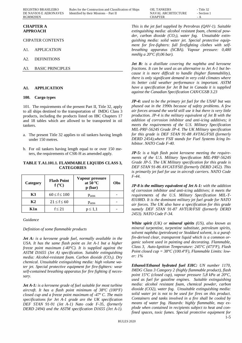
306. For access through vertical openings, or manholes, in
swash bulkheads, floors, girders and web frames providing
passage through the length and breadth of the compartment, the minimum opening is to be not less than 600 mm x 800
mm at a height of not more than 600 mm from the bottom
shell plating unless gratings or other foot holds are provided.
FIGURE F.E4.306.1. ACCESS THROUGH VERTICAL
OPENINGS
FIGURE F.E4.306.2. ACCESS THROUGH HORIZON-
TAL OPENINGS
307. For oil tankers of less than 5000 t deadweight, RBNA
may approve, in special circumstances, smaller dimensions
for the openings referred to in Paragraphs E4.305. and E4.306. , if the ability to traverse such openings or to re-
move an injured person can be proved to the satisfaction of
RBNA.
308. Access ladders of cargo tanks are to be fitted with
handrails and to be securely attached to the tank structure.
They are not to be fitted vertically, unless justified by the
size of the tanks. Rest platforms are to be provided at suita-
ble intervals of not more than 10 m.
400. Access to the pipe tunnels
401. The pipe tunnels in the double bottom are to comply
with the following requirements:
a. they are not to communicate with the engine room,
b. provision is to be made for at least two exits to the open
deck arranged at a maximum distance from each other.
One of these exits fitted with a watertight closure may
lead to the cargo pump room.
402. Where there is permanent access from a pipe tunnel to the main pump room, a watertight door is to be fitted and in
addition with the following:
a. in addition to the bridge operation, the watertight door is
to be capable of being manually closed from outside the
main pump room entrance,

REGISTRO BRASILEIRO Rules for the Construction and Classification of Ships OIL TANKERS - Title 32
DE NAVIOS E AERONAVES Identified by their Missions – Part II NAVAL ARCHITECTURE - Section 1
RGMM20EN CHAPTER - E
1-15 RULES 2020
b. the watertight door is to be kept closed during normal operations of the ship except when access to the pipe
tunnel is required.
403. A notice is to be affixed to the door to the effect that it
may not be left open.
500. Other accesses
501. Access to the forecastle spaces: containing sources of
ignition may be allowed through doors facing cargo area
provided the doors are located outside hazardous areas.
502. Access to the bow: every tanker is to be provided with
the means to enable the crew to gain safe access to the bow
even in severe weather conditions. Such means of access are
to be approved by RBNA.
503. Tank cleaning openings: ullage plugs, sighting ports
and tank cleaning openings are not to be arranged in en-
closed spaces.
600. Cofferdams
601. This Topic E4.600. is applicable to ships having class
notation K2 and K3.
602. Oil tight cofferdams adequately ventilated, having a
width large enough for easy access, are to be fitted for the
separation of all cargo tanks, of galleys below deck, ac-
commodations, boiler compartments, general cargo com-partments and machinery spaces containing propulsion ma-
chinery or wherever there is a source of ignition present.
603. Pump compartments designated only to oil and ballast
tanks can be considered as cofferdams according to these
Rules.
604. The cofferdam bulkheads adjacent to the cargo area
shall be vertical, and shall extend up to the exposed deck in
a single plane without any recesses.
605. Under specific conditions at RBNA discretion the
pump room when located under deck may be considered as
a cofferdam proved the requirements of Paragraph E3.403.
above are complied with.
606. A cofferdam below deck shall have access only from
the deck, and shall be watertight except for the ventilation
openings.
607. In oil tankers engaged in the transportation of special
cargo a cofferdam between a cargo tank and a fuel tank may
be required at RBNA discretion.
700. Compartments in hazardous zones
701. This Topic E4.700. is applicable to ships having class
notation K2, K1n, and K3 all oil tankers covered by the pre-
sent Title 32.
702. The arrangement of cofferdams in the cargo area shall be designed to comply with the following requirements:
a. Ventilated;
b. Fitted with means to verify the presence of gases;
c. Accessible for inspection and cleaning;
800. Openings and passages in the bulkheads for pip-
ing, shafts and electric cables
801. This Topic E4.800 is applicable to ships having class notation K2, K1n, and K3 all oil tankers covered by the pre-
sent Title 32.
802. The boundary of cofferdams limiting cargo tanks are
to be watertight.
803. No openings are allowed in the bulkheads limiting the
cargo area and the cargo tanks.
804. Passage of shafts/cables through the bulkheads at the
boundary of the Engine Room and a compartment in the cargo area or between the Engine Room and a compartment
inside the cargo area are allowed provided the following
conditions are complied with:
a. The sealing of the penetration of the shaft is gas tight,
approved by RBNA;
b. Adequate operating instructions are posted;
c. Electric cable and pipe penetrations are to be gas tight
and approved by RBNA;
d. Passages through an A-60 bulkhead as per SOLAS II.2
regulation 3 are equivalent to the bulkhead A-60 stand-
ard;
e. The bulkhead between the Engine Room and a service
compartment in the cargo area may be penetrated by pip-
ing provided the piping has no opening inside the service
compartment;
E5. SEGREGATION OF OIL AND WATER BAL-
LAST
100. Requirements for segregation of oil and water
ballast
101. Ships delivered after 31 December 1979 of 4,000 gross
tonnage and above other than oil tankers, and in oil tankers
delivered after 31 December 1979 of 150 gross tonnage and
above, no ballast water shall be carried in any oil fuel tank.
102. Where the need to carry large quantities of oil fuel*
render it necessary to carry ballast water which is not a clean
ballast in any oil fuel tank, such ballast water shall be dis-

REGISTRO BRASILEIRO Rules for the Construction and Classification of Ships OIL TANKERS - Title 32
DE NAVIOS E AERONAVES Identified by their Missions – Part II NAVAL ARCHITECTURE - Section 1
RGMM20EN CHAPTER - E
1-16 RULES 2020
charged to reception facilities or into the sea using the oil
filtering equipment and an entry shall be made in the Oil Record Book to this effect.
* IMO interpretation: The phrase "large quantities of oil
fuel" refers to ships which are required to stay at sea for ex-
tended periods because of the particular nature of their oper-
ation and trade. Under the circumstances considered these
ships would be required to fill their empty oil fuel tanks with
water ballast in order to maintain sufficient stability and safe
navigation conditions. Such ships may include inter alia
certain large fishing vessels or ocean going tugs. Certain
other types of ships which for reasons of safety, such as sta-
bility, may be required to carry ballast in oil fuel tanks may also be included in this category.
103. In a ship of 400 gross tonnage and above, for which
the building contract is placed after 1 January 1982 or, in the
absence of a building contract, the keel of which is laid or
which is at a similar stage of construction after 1 July 1982,
oil shall not be carried in a forepeak tank or a tank forward
of the collision bulkhead.
104. All ships other than those subject to Paragraphs
E5.101. and E5.103. of this Rules shall comply with the provisions of those paragraphs as far as is reasonable and
practicable.**
** When the separation of oil fuel tanks and water ballast
tanks is unreasonable or impracticable, ballast water may be
carried in oil fuel tanks, provided that such ballast water is
discharged into the sea in compliance with regulations 15.2,
15.3, 15.5 and 15.6 or into reception facilities in compliance
with regulation 15.9 of MARPOL Annex 1 Regulation 15.

REGISTRO BRASILEIRO Rules for the Construction and Classification of Ships OIL TANKERS - Title 32
DE NAVIOS E AERONAVES Identified by their Missions – Part II NAVAL ARCHITECTURE - Section 1
RGMM20EN CHAPTER - G
1-17 RULES 2020
CHAPTER G
CAPACITIES AND COMPARTMENTING
CHAPTER CONTENTS
G1. SUBDIVISION OF THE HULL
G2. OIL TANKERS WITH DEADWEGHT ≥ 5000 T
G3. OIL TANKERS WITH DEADWEGHT < 5000 T
G4. SLOP TANKS
Guidance
Chapter G in its entirety is applicable to all oil tankers cov-
ered by the present Title 32.
End of guidance
G1. SUBDIVISION OF THE HULL
100. Main transverse bulkheads
101. See Part II, Title 11
200. Double-hull– protection of cargo tank in the event
of stranding, collision or leak
201. The oil tankers covered by this Title with deadweight
smaller 5000 TDW, shall be built with double bottom and
double side shell in the region of the cargo tanks.
202. The carriage of oil in any space forward of the colli-
sion bulkhead forward or abaft of the aft collision bulkhead
is not allowed.
203. Oil tankers with GT < 500 flying a Brazilian Flag shall comply with the regulations of NORMAM 01, Chapter 5.
204. Oil tankers with GT < 500 flying foreign Flag shall
comply with National regulations of the flag. In case there
are no such regulations, the requirements of the present Title
32 and of IMO instruments shall be complied with as far as
possible.
G2. OIL TANKERS WITH DEADWEGHT ≥ 5000 T
100. General
101. Every oil tanker with 5000 DWT tons deadweight and
above the entire region of cargo tanks shall be protected by
ballast tanks or by spaces not carrying fuel oil or oil cargo in
accordance with the prescriptions that follow.
200. Wing tanks or spaces
201. Wing tanks or spaces shall extend either for the full
depth of the ship's side or from the top of the double bottom
to the uppermost deck, disregarding a rounded gunwale
where fitted.
202. They shall be arranged such that the cargo tanks are
located inboard of the moulded line of the side shell plating
nowhere less than the distance w which, as shown in Figure
F.G2.301.1. is measured at any cross-section at right angles
to the side shell, as specified below:
w = 0,5 + (TDW/20000) m
where:
TDW: Deadweight
w: 2,0 m, whichever is lesser, with minimum value = 1,0 m.
300. Tanks or spaces of the double bottom
301. At any cross-section, the height of a tank or double
bottom space shall be such that the distance h between the
bottom of the cargo tanks and the moulded line of the bot-
tom plating, measured at right angles to the bottom plating
as shown in Figure F.G2.301.1., is not less than the follow-
ing value:
h = B/15 m
or
h = 2,0 m, whichever is lesser,
with minimum value of h = 1,0 m.
FIGUE F.G2.301.1. BOUNDARY LINES OF THE-
CARGO TANKS
302. The requirement of Paragraph G2.301. above can be waived provided that the design of the tanker is such that the
cargo pressure plus the vapor exerted on the bottom plating
forming a single boundary between the cargo and the sea
does not exceed the external hydrostatic pressure as ex-
pressed in the following formula:
f hc ρc g + 100 Δp ≤ dn ρs g
Where:
f: safety factor = 1,1
REGISTRO BRASILEIRO Rules for the Construction and Classification of Ships OIL TANKERS - Title 32
DE NAVIOS E AERONAVES Identified by their Missions – Part II NAVAL ARCHITECTURE - Section 1
RGMM20EN CHAPTER - G
1-18 RULES 2020
hc: cargo height in contact with the bottom plating, in m.
ρc: maximum density of the cargo, in t/m3
g: standard acceleration gravity, 9,81 m/s2
Δp: maximum pressure of regulation of the valve PV, in
bars
dn: minimum draft of operation under any conditions of
cargo expected, in metres
ρs: water density, in t/m3
303. Any horizontal partition necessary to fulfil the above
requirement shall be situated at a height not less than B/6 or
6 m, whichever is less, but not more than 0,6 D above the
baseline, where D is the moulded depth amidships.
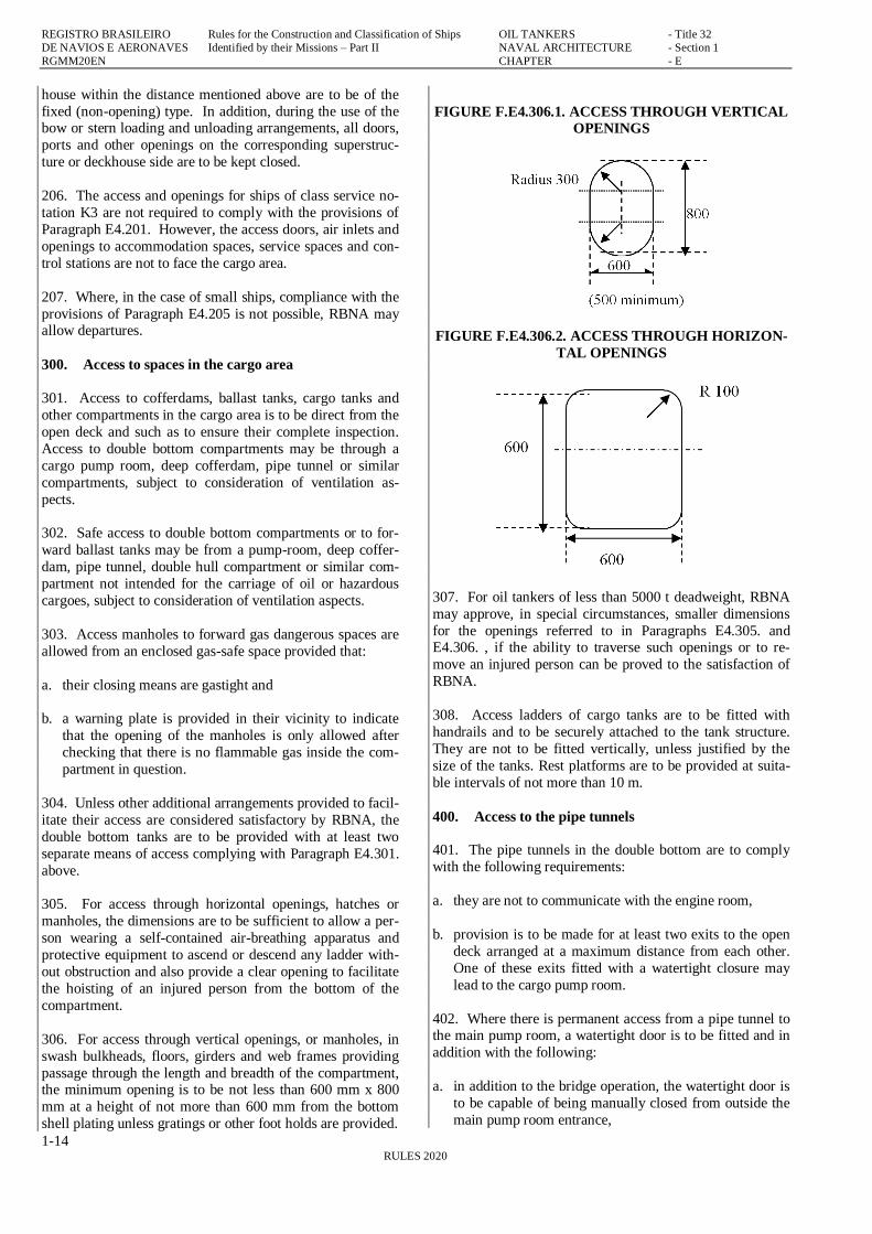
304. The location of wing tanks or spaces shall be as de-
fined in Paragraph G2.301. above, except that, below the
level of 1.5 h above the baseline where h is defined as in the
formula above, the cargo tank boundary line can be vertical
up to the bottom plating, as shown in Figure F.G2.304.1.
FIGURA F.G2.304.1. BOUNDARY LINES OF THE-
CARGO TANKS BELOW 1.5 h
305. When the distances h and w were different (Figure
F.G2.301.1.), the distance w shall have preference at levels greater than 1.5 h above the baseline, as shown in Figure
F.G2.304.1.
306. Small wells in cargo tanks may get into the double
bottom below the boundary line set by the distance h pro-
vided that such small wells are so small as possible and that
the distance between the bottom of the slump tank and the
vessel bottom plating is not less than 0.5 h.
307. The cargo pump rooms shall be fitted with double bot-
tom with height h above the baseline not less than that re-quired in Paragraph G2.301. above.
400. Size limitation of the tanks to ships with 5000 T
deadweight or greater
401. For ships delivered in 1 January 2010 or after, as de-
fined in Regulation 1.28.8 of the Annex I of the MARPOL
73/78, the maximum tank length and the accidental oil-spills
shall be calculated in accordance with Regulation 23 of that Annex.
402. For ships delivered before 1 January 2010, as defined
in Rule 1.28.8 of the Annex I of the MARPOL 73/78, the
maximum tank length and the accidental spill of oil shall be
calculated in accordance with Rules 25 and 26 of that An-
nex.
G3. OIL TANKERS WITH DEADWEGHT < 5000 T
100. General
101. There shall be endowed of at least of tanks or double
bottom spaces having height such that the distance h speci-
fied in Paragraph G2.301. is not less than the following val-
ue:
h = B/15 m
with minimum value of: h = 0,76 m;
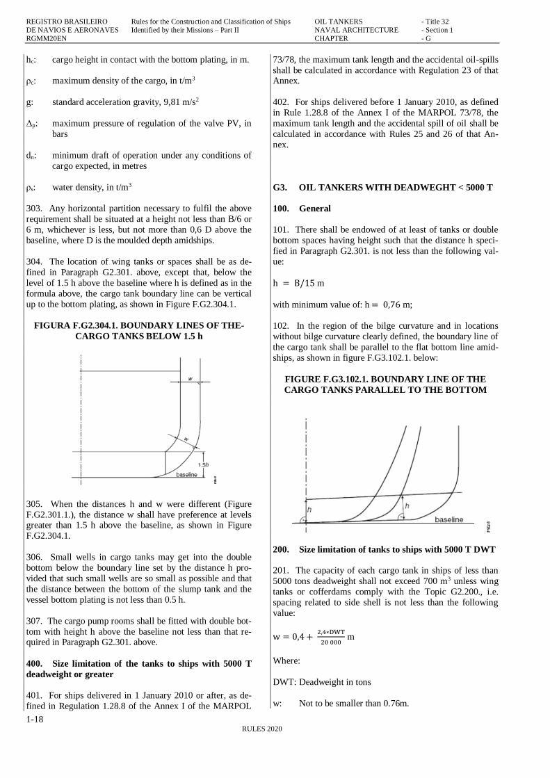
102. In the region of the bilge curvature and in locations
without bilge curvature clearly defined, the boundary line of
the cargo tank shall be parallel to the flat bottom line amid-
ships, as shown in figure F.G3.102.1. below:
FIGURE F.G3.102.1. BOUNDARY LINE OF THE
CARGO TANKS PARALLEL TO THE BOTTOM
200. Size limitation of tanks to ships with 5000 T DWT
201. The capacity of each cargo tank in ships of less than
5000 tons deadweight shall not exceed 700 m3 unless wing
tanks or cofferdams comply with the Topic G2.200., i.e.
spacing related to side shell is not less than the following
value:
w = 0,4 + 2,4∗DWT
20 000 m
Where:
DWT: Deadweight in tons
w: Not to be smaller than 0.76m.

REGISTRO BRASILEIRO Rules for the Construction and Classification of Ships OIL TANKERS - Title 32
DE NAVIOS E AERONAVES Identified by their Missions – Part II NAVAL ARCHITECTURE - Section 1
RGMM20EN CHAPTER - G
1-19 RULES 2020
300. IACS Unified Interpretation MPC87
301. Valves for oil fuel tanks located in accordance with the
provisions of Subchapter G2 and G3 above (MARPOL
regulation I/12A) may be treated in a manner similar to the
treatment of suction wells arranged at a distance from the
ship’s bottom of not less than h/2 (see Figure F.G3.301.1.
below).
302. Valves for tanks which are permitted to be located at a
distance from the ship’s bottom or side at a distance less
than h or w , respectively, in accordance with the accidental
oil fuel outflow performance standard of MARPOL regula-tion I/12A.11 may be arranged at the distance less than h or
w , respectively.
303. Fuel tank air escape pipes and overflow pipes are not
considered as part of ‘lines of fuel oil piping” and therefore
may be located at a distance from the ship’s side of less than
w .
FIGURE F.G3.301.1. LOCATION OF AIR ESCAPE PIPES AND OVERFLOW PIPES
REGISTRO BRASILEIRO Rules for the Construction and Classification of Ships OIL TANKERS - Title 32
DE NAVIOS E AERONAVES Identified by their Missions – Part II NAVAL ARCHITECTURE - Section 1
RGMM20EN CHAPTER - H
1-20 RULES 2020
CHAPTER H
CONDITIONS OF LOADING, BUOYANCY AND
STABILITY
CHAPTER CONTENTS
H1. FREEBOARD
See Part II, Title 11
H2. LIGHTSHIP WEIGHT
See Part II, Title 11
H3. LOADING CONDITIONS
See Part II, Title 11
H4. BUOYANCY, HULL SUBDIVISION
See Part II, Title 11
H5. STABILITY
H6. DAMAGE STABILITY
H6. INTACT STABILITY OF TANKERS DURING
LIQUID TRANSFER OPERATIONS
Guidance
Chapter H in its entirety is applicable to ships having class notation: K1n, K2 and K3.
End of guidance
H5. STABILITY
100. Intact Stability
101. For all oil tankers, covered by the present Title 32 the
class notation will be assigned after it has been shown that its intact stability is adequate for the intended mission.
102. Sufficient stability means compliance with the Interna-
tional Code on Intact Stability of IMO adopted by resolution
IMO resolution. MSC. 267 (85) of 04.12.2008, taking into
account the ship type and size.
103. Ships with GT <500 under the Brazilian Flag shall
comply with the requirements of NORMAN 01. For ships
under foreign flags, RBNA may accept National Regula-
tions and, in the absence of those, compliance with IMO instruments as far as possible.
104. Oil tankers with GT equal to or larger than 5000 TDW
shall comply with the regulations of MARPOL Annex I
Regulation 27, as per IMO IS Code Part A Section 3.1.
105. Evidence of approval by RBNA may be accepted for
the purposes of classification.
106. The intact stability calculations shall be based on the
following loading conditions:
a. All the loading conditions are intended to be included in
trim and stability booklet for examination.
b. New cases are subject to prior examination by RBNA
before loading, Alternatively, an approved loading in-
strument capable of performing damage stability calcula-
tions, in accordance with the requirements of this Sub-
chapter H5 may be used.
c. For ships covered by this Chapter the following loading
cases shall be included in the trim and stability booklet:
c.1. Ship in the departure condition fully loaded at the
summer load water line, with evenly distributed
load for all cargo tanks and bunkers and consuma-
bles to 100%;
c.2. Same condition above, but with 10% stores in bun-
kers and fuel;
c.3. Ship in the departure condition loaded with a cargo
density such that filling all cargo tanks, with bun-kers and consumables to 100%, the ship reaches a
depth less than the summer load water line;
c.4. Same condition above, but with 10% stores in bun-
kers and fuel;
c.5. Ship in the departure condition fully loaded at the
summer load water line, with cargo tanks not com-
pletely filled and with bunkers and consumables to
100%;
c.6. Same condition above, but with 10% stores in bun-kers and fuel;
c.7. Two load conditions corresponding to the load seg-
regates different situations in order to have handily
tanks and bunkers and consumables to 100%. When
it is impossible to segregate, these conditions shall
be replaced by load conditions with the same spe-
cific weight and clearance of loading of cargo
tanks;
c.8. Same condition above, but with 10% stores in bun-kers and fuel;
d. For oil tankers with segregated ballast tanks, the light
ship condition with segregated ballast is also to be in-
cluded in the stability and trim.
107. Liquid transfer operations: ships with certain subdivi-
sions may be subject to instability (lolling) during liquid
transfer operations such as loading, unloading and ballast-
ing. To prevent the effect of lolling during these operations,
the design of ships with deadweight greater than 5000 T shall be such as to meet the following criteria:
REGISTRO BRASILEIRO Rules for the Construction and Classification of Ships OIL TANKERS - Title 32
DE NAVIOS E AERONAVES Identified by their Missions – Part II NAVAL ARCHITECTURE - Section 1
RGMM20EN CHAPTER - H
1-21 RULES 2020
a. the intact stability criteria reported above shall be met in
order for the worst condition possible of cargo and bal-last and establish, consistent with good operating prac-
tice, including intermediate stages of liquid transfer op-
erations. In all conditions the ballast tanks shall be as-
sumed to be taking clearance in the loading;
b. the initial metacentric height GM0 in metres, corrected
for the free surface effect measured with 0° heel, shall
not be less than 0.15. For the purposes of calculating of
GM0, free surface corrections shall be based on the mo-
ment of inertia of adequate free surface
c. the ship is to be loaded with:
c.1. all the cargo tanks filled to a level corresponding to
the maximum combined total of vertical moment of
volume added to the moment of inertia of free sur-
face in 0° heel, for each individual tank;
c.2. load density corresponding to the deadweight avail-
able in displacement in which transversal KM cross reaches a minimum value
c.3. 100% consumables in the departure
c.4. 1% of the total ballast water capacity. The effect of
maximum free surface shall be assumed in all the
ballast tanks.
H6. DAMAGE STABILITY
100. Calculation of damage stability
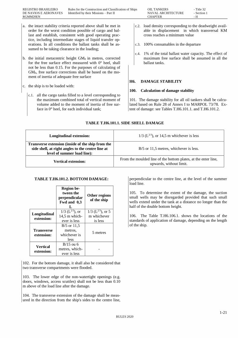
101. The damage stability for all oil tankers shall be calcu-
lated based on Rule 28 of Annex I to MARPOL 73/78. Ex-
tent of damage: see Tables T.H6.101.1. and T.H6.101.2.
TABLE T.H6.101.1. SIDE SHELL DAMAGE
Longitudinal extension: 1/3 (L2/3), or 14,5 m whichever is less
Transverse extension (inside of the ship from the
side shell, at right angles to the centre line at
level of summer load line):
B/5 or 11,5 metres, whichever is less.
Vertical extension: From the moulded line of the bottom plates, at the enter line,
upwards, without limit.
TABLE T.H6.101.2. BOTTOM DAMAGE:
Region be-
tween the
perpendicular
Fwd and 0,3
L
Other regions
of the ship
Longitudinal
extension:
1/3 (L2/3), or
14,5 m which-
ever is less
1/3 (L2/3), or 5
m whichever
is less
Transverse
extension:
B/5 or 11,5
metros,
whichever is
less
5 metres
Vertical
extension:
B/15 ou 6
metres, which-
ever is less
-
102. For the bottom damage, it shall also be considered that
two transverse compartments were flooded.
103. The lower edge of the non-watertight openings (e.g.
doors, windows, access scuttles) shall not be less than 0.10
m above of the load line after the damage.
104. The transverse extension of the damage shall be meas-
ured in the direction from the ship's sides to the centre line,
perpendicular to the centre line, at the level of the summer
load line.
105. To determine the extent of the damage, the suction small wells may be disregarded provided that such small
wells extend under the tank at a distance no longer than the
half of the double bottom height.
106. The Table T.H6.106.1. shows the locations of the
standards of application of damage, depending on the length
of the ship.

REGISTRO BRASILEIRO Rules for the Construction and Classification of Ships OIL TANKERS - Title 32
DE NAVIOS E AERONAVES Identified by their Missions – Part II NAVAL ARCHITECTURE - Section 1
RGMM20EN CHAPTER - H
1-22 RULES 2020
TABLE T.H6.106.1. DAMAGE STANDARDS
Ship’s
length (m)
Damage in
whichever
point of the
length
Damage
between
transverse
bulkheads
Flooded
Engine
Room
LLL ≤100 No Yes (1) (2) No
100 < LLL ≤ 150
No Yes (1) No
150 < LLL ≤ 225
Yes No Yes, only
LLL > 225 Yes No Yes
(1) Non-flooded Engine Room
(2) Exemptions from survival in Topic H5.600. below can
be accepted by RBNA under case by case analysis
108. The metacentric heights (GM), righting arms (GZ) and
positions of the centre of gravity (KG) to assess the final
conditions of survival shall be calculated by the constant
displacement method (lost buoyancy).
109. Oil tankers shall be regarded as complying with the damage stability criteria if the following requirements are
met:
a. The final waterline, taking into account sinkage, heel and
trim, shall be below the lower edge of any opening
through which progressive flooding may take place.
Such openings shall include air-pipes and those which
are closed by means of weather tight doors or hatch co-
vers and may exclude those openings closed by means of
watertight manhole covers and flush scuttles, small wa-
tertight cargo tank hatch covers which maintain the high
integrity of the deck, remotely operated watertight slid-ing doors, and side scuttles of the non-opening type.
b. In the final stage of flooding, the angle of heel due to
unsymmetrical flooding shall not exceed 25°, provided
that this angle may be increased up to 30° if no deck
edge immersion occurs.
c. The stability in the final stage of flooding shall be inves-
tigated and may be regarded as sufficient if the righting
lever curve has at least a range of 20° beyond the posi-
tion of equilibrium in association with a maximum re-sidual righting lever of at least 0.1 metre within the 20°
range; the area under the curve within this range shall
not be less than 0.0175 metre radians. Unprotected open-
ings shall not be immersed within this range unless the
space concerned is assumed to be flooded. Within this
range, the immersion of any of the openings listed in
Paragraph H6.109.a. and other openings capable of being
closed watertight may be permitted.
d. Administration shall be satisfied that the stability is suf-
ficient during intermediate stages of flooding.
e. Equalization arrangements requiring mechanical aids
such as valves or cross-levelling pipes, if fitted, shall not
be considered for the purpose of reducing an angle of
heel or attaining the minimum range of residual stability
to meet the requirements of Paragraphs H6.109.a., H6.109.b. and H6.109.c. above and sufficient residual
stability shall be maintained during all stages where
equalization is used. Spaces which are linked by ducts
of a large cross-sectional area may be considered to be
common.
110. Where the damage involving transverse bulkheads is
envisaged as specified in subparagraphs 1.1 and 1.2 of this
regulation (see guidance below), transverse watertight bulk-
heads shall be spaced at least at a distance equal to the longi-
tudinal extent of assumed damage specified in Table
T.H6.101.1. (Side shell damage) above in order to be con-sidered effective. Where transverse bulkhead are spaced at a
lesser distance, one or more of these bulkheads within such
extent of damage shall be assumed as non-existent for the
purpose of determining flooded compartments.
Guidance
This guidance note is from subparagraphs 1.1 and 1.2 of
Regulation 28, MARPOL 74/78, Annex I.
Every oil tanker delivered after 31 December 1979, as de-fined in regulation 1.28.2, of 150 gross tonnage and above,
shall comply with the subdivision and damage stability cri-
teria as specified in paragraph 3 of this regulation, after the
assumed side or bottom damage as specified in paragraph 2
of this regulation, for any operating draught reflecting actu-
al partial or full load conditions consistent with trim and
strength of the ship as well as relative densities of the cargo.
Such damage shall be applied to all conceivable locations
along the length of the ship as follows:
1) in tankers of more than 225 metres in length, anywhere
in the ship's length;
2) in tankers of more than 150 metres, but not exceeding
225 metres in length, anywhere in the ship's length except
involving either after or forward bulkhead bounding the
machinery space located aft. The machinery space shall be
treated as a single floodable compartment; and
3) in tankers not exceeding 150 metres in length, anywhere
in the ship's length between adjacent transverse bulkheads
with the exception of the machinery space. For tankers of
100 metres or less in length where all requirements of para-graph 3 of this regulation cannot be fulfilled without mate-
rially impairing the operational qualities of the ship, Admin-
istrations may allow relaxations from these requirements.
End of guidance
111. Where the damage between transverse watertight
bulkheads is considered in the Table H6.T.106.1., no main
transverse bulkhead or a transverse bulkhead bounding side
tanks or double bottom tanks shall be assumed damaged,
unless:
a. the spacing between adjacent bulkheads is less than the
longitudinal extension specified in Paragraph H6.101.; or

REGISTRO BRASILEIRO Rules for the Construction and Classification of Ships OIL TANKERS - Title 32
DE NAVIOS E AERONAVES Identified by their Missions – Part II NAVAL ARCHITECTURE - Section 1
RGMM20EN CHAPTER - H
1-23 RULES 2020
b. there is a step or recess in a transverse bulkhead of more than 3.05 metres in length, located within the extent of
penetration of assumed damage. The step formed by the
after peak bulkhead and after peak top shall not be re-
garded as a step for the purpose of this regulation.
112. In the case of pipes, ducts or tunnels are located within
the extent of penetration of the damage as specified in
Paragraph H6.101., the arrangement shall be made so that
the progressive flooding cannot extend to compartments
other than those considered non-flooded in the calculation
for each case of damage.
200. Permeability
201. The value of permeability, in general, will be 95%
(ninety five percent), unless there is a statement specifying
different value. In all cases, the minimum values are:
store rooms 60%
machinery spaces: 85%;
accommodations: 95%;
double bottoms, fuel tanks,
ballast etc., depending on their
functions, are considered full or
empty in the condition of the ship in draft
maximum allowed 0% ou 95%
202. Whenever a damage below standard imply in more severe conditions of heel, trim and reserve buoyancy re-
serve, the criteria for damage stability shall be taken into
consideration
203. The Engine Room will be considered as a single com-
partment, i.e. the end bulkheads of Engine Room will be
deemed intact, so considering as a floodable compartment.
For vessels of more than 150 m in length, but not more than
225 m.
300. Survival requirements
301. In the damage stability study it will be demonstrated,
in the final stage of balance in flooding, that:
a. the final waterline, taking into account sinkage, heel and
trim, shall be below the lower edge of any opening
through which progressive flooding may take place.
Such openings shall include air-pipes and those which
are closed by means of weathertight doors or hatch co-
vers and may exclude those openings closed by means of
watertight manhole covers and flush scuttles, small wa-
tertight cargo tank hatch covers which maintain the high integrity of the deck, remotely operated watertight slid-
ing doors, and side scuttles of the non-opening type.
b. in the final stage of flooding, the angle of heel due to
unsymmetrical flooding shall not exceed 25°, provided
that this angle may be increased up to 30° if no deck
edge immersion occurs;
c. the stability in the final stage of flooding shall be inves-
tigated and may be regarded as sufficient if the righting
lever curve has at least a range of 20° beyond the posi-
tion of equilibrium in association with a maximum re-
sidual righting lever of at least 0.1 metre within the 20°
range; the area under the curve within this range shall
not be less than 0.0175 metre radians. Unprotected
openings shall not be immersed within this range unless
the space concerned is assumed to be flooded. Within
this range, the immersion of any of the openings listed in
H6.101.a and other openings capable of being closed wa-tertight may be permitted;
d. the minimum values of stability shall extend for a mini-
mum range of 20 (twenty) degrees beyond the point of
balance.
302. The requirements of Paragraph H6.101. above shall be
confirmed by calculations which take into consideration the
design characteristics of the ship, the arrangements, configu-
ration and contents of the damaged compartments; and the
distribution, relative densities and the free surface effect of liquids. The calculations shall be based on the following:
Account shall be taken of any empty or partially filled tank,
the relative density of cargoes carried, as well as any out-
flow of liquids from damaged compartments. The permea-
bilities assumed for spaces flooded as a result of damage
shall be according to Paragraph H6.201. above.
303. For oil tankers with TDW > 20.000, the hypotheses of
damage assumed, concerning bottom damage in Paragraph
H6.101., shall be supplemented by the damages due to bot-
tom touching of the Table T.H6.303.1. below.
TABLE T.H6.303.1. BOTTOM DAMAGE EXTENSION
FOR TDW > 20.000
Deadweight Longitudinal
extension
Transverse
extension
vertical
extension
< 75000 t 0,4 LLL (1) B/3 (2)
≥75000 t 0,6 LLL (1) B/3 (2)
(1) Measured from the forward perpendicular
(2) External hull rupture
304. The requirements of Paragraph H6.301. shall consid-
ered for this type of damage.
305. Equalization provisions - provisions for equalization
employing mechanical aid such as valves or transverse pip-
ing for levelling, if installed, shall not be taken into consid-
eration for the purpose of reducing the heel angle or achiev-
ing the minimum residual stability extension intended to
fulfil the requirements of Paragraph H6.301. Sufficient re-sidual stability shall be maintained at all stages, whenever
equalizing process are used.
306. Compartments that are connected by ducts of large
cross section area complete one single compartment only.

REGISTRO BRASILEIRO Rules for the Construction and Classification of Ships OIL TANKERS - Title 32
DE NAVIOS E AERONAVES Identified by their Missions – Part II NAVAL ARCHITECTURE - Section 1
RGMM20EN CHAPTER - H
1-24 RULES 2020
307. The following information shall be available to an oil tanker’s captain, in the approved form:
a. information relating to loading and load distribution nec-
essary to ensure compliance with the stability require-
ments; and
b. information about the capacity of the ship to comply
with the stability criteria as determined in Paragraph
H6.301., including the effects of the application stand-
ards of damages, shown in Table T.H6.106.1.
H7. INTACT STABILITY OF TANKERS WITH GT
≥ 500 DURING LIQUID TRANSFER OPERA-
TIONS
100. Approach
101. This Subchapter H6. for tankers (i.e. vessels designed
to carry liquid in bulk) is developed from MSC/Circ.706
(MEPC/Circ.304) containing recommendations for existing
oil tankers. The phenomenon of lolling is considered by IACS to be a safety issue for double hull tankers, as well as
for other tankers having exceptionally wide cargo tanks (i.e.
having cargo tank breadths greater than 60% of the vessel s
maximum beam), which shall be solved for every vulnerable
tanker. The solutions shall not be limited only to tankers
subject to MARPOL.
102. This Subchapter H6. applies to a tanker which is not
subject to MARPOL, Annex I, Reg. 25A. Alternatively
MARPOL, Annex I, Reg. 25A could be applied as a matter
of equivalence.
103. Liquid transfer operations include cargo loading and
unloading, lightering, ballasting and deballasting, ballast
water exchange, and tank cleaning operations.
104. Every tanker is to comply with the intact stability cri-
teria specified in Paragraphs H6.201. and H6.202. for any
operating draught reflecting actual, partial or full load condi-
tions, including the intermediate stages of liquid transfer
operations.
200. Stability criteria
201. In port, the initial metacentric height GMo is not to be
less than 0.15m. Positive intact stability is to extend from
the initial equilibrium position at which GMo is calculated
over a range of at least 20 degrees to port and to starboard.
202. At sea, the intact stability criteria contained in para-
graphs 3.1.2.1 to 3.1.2.4 of IMO Intact Stability Code, are
applicable, or the criteria contained in the national require-
ments of RBNA if the national stability requirements pro-
vide at least an equivalent degree of safety.
300. Loading conditions
301. For all loading conditions in port and at sea, including
intermediate stages of liquid transfer operations, the initial
metacentric height and the righting lever curve are to be cor-
rected for the effect of free surfaces of liquids in tanks.
302. The intact stability criteria preferably is to be met by
design of the ship, i.e. the design shall allow for maximum
free surface effects in all cargo, ballast and consumables
tanks during liquid transfer operations.
303. If the intact stability criteria are not met through de-
sign of the ship alone, the Master is to be provided with clear instructions covering the operational restrictions and
methods necessary to ensure compliance with these criteria
during liquid transfer operations. These instructions shall
be simple and concise, and:
a. in a language understood by the officer-in-charge of
transfer operations;
b. require no more than minimal mathematical calculations
by the officer-in-charge;
c. indicate the maximum number of cargo and ballast tanks
which may be slack under any possible condition of liq-
uid transfer, and
d. provide pre-planned sequences of cargo/ballast transfer
operations; which indicate the cargo and ballast tanks
which may be slack to satisfy the stability criteria under
any specific condition of liquid transfer, including possi-
ble range of cargo densities. The slack tanks may vary
during stages of the transfer operations and be any com-
bination which satisfied the stability criteria.
e. provide instructions for pre-planning other sequences of
cargo/ballast transfer operations, including use of stabil-
ity performance criteria in graphical or tabular form
which enable comparisons of required and attained sta-
bility. These instructions for pre-planning other se-
quences, in relation to individual vessels, shall take ac-
count of:
e.1. the degree of criticality with respect to the number
of tanks which can simultaneously have maximum
free surface effects at any stage of liquid transfer operations;
e.2. the means provided to the officer-in-charge to mon-
itor and assess the effects on stability and hull
strength throughout the transfer operations;
e.3. the need to give sufficient warning of an impending
critical condition by reference to suitable margins
(and the rate and direction of change) of the appro-
priate stability and hull strength parameters. If ap-
propriate, the instructions shall include safe proce-dures for suspending transfer operations until a
suitable plan of remedial action has been evaluated.

REGISTRO BRASILEIRO Rules for the Construction and Classification of Ships OIL TANKERS - Title 32
DE NAVIOS E AERONAVES Identified by their Missions – Part II NAVAL ARCHITECTURE - Section 1
RGMM20EN CHAPTER - H
1-25 RULES 2020
e.4. the use of on-line shipboard computer systems dur-
ing all liquid transfer operations, processing cargo and ballast tank ullage data and cargo densities to
continuously monitor the vessel s stability and hull
strength and, when necessary, to provide effective
warning of an impending critical situation, possibly
automatic shut-down, and evaluation of possible
remedial actions. The use of such systems is to be
encouraged.
f. provide for corrective actions to be taken by the officer-
in-charge in case of unexpected technical difficulties
with recommended pre-planned transfer operations and
in case of emergency situations. A general reference to the vessel s shipboard oil pollution emergency plan may
be included.
g. be prominently displayed:
g.1. in the approval trim and stability booklet;
g.2. at the cargo/ballast transfer control station;
g.3. in any computer software by which intact stability
is monitored or calculations performed;
g.4. in any computer software by which hull strength is
monitored or calculations performed.
Rgmm20en-PIIT32S1-abdegh-00