Embed Size (px)
Citation preview

M A T E R I A L S C H A R A C T E R I Z A T I O N 6 0 ( 2 0 0 9 ) 1 4 5 4 – 1 4 6 2
ava i l ab l e a t www.sc i enced i rec t . com
www.e l sev i e r. com/ loca te /matcha r
Characterization of microstructural damage due to low-cyclefatigue by EBSD observation
Masayuki Kamaya⁎
Institute of Nuclear Safety System, Inc., 64 Sata, Mihama-cho, Mikata-gun, Fukui 919-1205, Japan
A R T I C L E D A T A
⁎ Tel.:+81 770 379114; fax: +81 770 372009.E-mail address: [email protected].
1044-5803/$ – see front matter © 2009 Elsevidoi:10.1016/j.matchar.2009.07.003
A B S T R A C T
Article history:Received 14 April 2009Received in revised form 25 June 2009Accepted 7 July 2009
Electron backscatter diffraction (EBSD) in conjunction with scanning electron microscopywas used to assess the damage due to cyclic or uniform strain. Samples of Type 316 stainlesssteel after fatigue and tensile tests were prepared for EBSD observation and themisorientation angle between neighboring points (local misorientation) was evaluated. Itwas shown that the local misorientation developed due to the cyclic and uniform strain andthat its spatial distribution was not uniform. In fatigue samples, the area of large localmisorientation tended to form clusters, whereas it localized to the grain boundaries in thetensile samples, and the magnitude of local misorientation and the degree of thelocalization increased with the strain amplitude. The degree of localization wasquantified via statistical processing of the measured data. It was also shown that thesource of damage (cyclic or uniform strain) and the loading direction could be deduced fromthe EBSD observations of the damaged sample.
© 2009 Elsevier Inc. All rights reserved.
Keywords:Electron backscatter diffraction (EBSD)Stainless steelPlastic deformationLow-cycle fatigueMisorientation
1. Introduction
When a cyclic load is applied to amaterial, small cracks areinitiated from slip steps and grain boundaries. During theincubation period before crack initiation, damage due to cyclicloading (fatigue damage) accumulates in the material. In thelow-cycle region, strain is thought to be a driving force fordamage accumulation and several models for predictingfatigue life have been suggested based on the applied strain[1–3]. If the accumulated damage exceeds the limit, a crack isinitiated. The important feature of the crack initiation is thatcracks are not initiated from all the grains and grain bound-aries, but from only selected ones. In a polycrystalline mate-rial, stress and strain are distributed inhomogeneously inspace at the microstructural level even under uniform cyclicstrain conditions [4–6]. It was shown that such inhomogeneityis related to the geometry and crystallographic orientation ofthe grains. Anisotropic mechanical properties of each crystalproduce localized strain, and fatigue cracks are initiated fromthese localized areas [7,8]. Therefore, it is important to know
er Inc. All rights reserved
the magnitude of the accumulated localized strain in order toevaluate the degree of fatigue damage.
Since cyclic plastic strain causes crystallographic slips andthe geometrically necessary dislocations, the crystal orienta-tion fluctuates even in the same grain depending on thedegree of strain. Electron backscatter diffraction (EBSD) inconjunctionwith scanning electronmicroscopy (SEM) is one ofthemost promising techniques tomeasure the change in localcrystal orientation. By using commercial apparatuses for EBSDmeasurement, we can identify crystal orientations by scan-ning the surface of samples. By evaluating the misorientationangle between neighboring points (hereafter called “localmisorientation”), it is possible to determine the magnitudeof the local plastic strain [9,10]. In a previous study by thepresent author [11], the spatial distribution of the localmisorientation was compared with that of nominal strainmeasured by the image correlation technique, and it was re-vealed that the local misorientation was consistent with thedensity of the geometrically necessary dislocations ratherthan the magnitude of nominal strain, which is defined as the
.

Table 2 –Mechanical properties of test material.
0.2% proofstrength
Tensilestrength
Elongation Reduction ofarea
294 MPa 602 MPa 0.60 0.76
1455M A T E R I A L S C H A R A C T E R I Z A T I O N 6 0 ( 2 0 0 9 ) 1 4 5 4 – 1 4 6 2
deformation per unit length [12]. It was shown that the mag-nitude of the local misorientation correlates well with theinduced macroscopic plastic strain [13].
The present study set out to characterize the inhomoge-neous distribution of the local misorientation caused by fa-tigue loading. Knowledge of where and how much the localmisorientation has accumulated will help to clarify the pro-cess of damage accumulation and enable us to predict thecrack initiation. Samples with different degrees of appliedstrain were investigated. Also, samples that had been strainedby tensile tests were prepared for the same observation. It wasrevealed that pre-strain before fatigue loading does not reducethe fatigue life, although the local misorientation evolves dueto plastic deformation [14,15]. This implies that there is adifference in the evolution of the localmisorientation betweenthe cyclic strain and the uniform strain. A comparison of thelocal misorientation under different loadings is expected tohelp characterize the fatigue damage.
The material used for the observations was Type 316stainless steel. Specimens were subjected to the fatigue testunder different degrees of the applied strain up to a nominalstrain of 1.2% at ambient temperature. The deformed samplewas prepared by a tensile test up to a nominal plastic strain of7.8%. The local misorientations were identified from thecrystal orientations obtained using EBSD, and subjected tofurther analysis.
2. Experimental Procedure
The observed material was a solution heat-treated Type 316austenitic stainless steel, whose alloying constituents andmechanical properties are shown in Tables 1 and 2, respec-tively. The material had an approximately equiaxial grainstructure with an average grain diameter of 30 μm. Round barspecimens (gauge length=20 mm and diameter=10 mm) forthe fatigue test and plate specimens (gauge length=20 mmand cross section=2×4 mm) for the tensile test weremachined. The surface of the fatigue specimens was polishedup to 3 μmdiamond paste. Both tests were performed in air, atroom temperature.
Fully reversed axial strain-controlled fatigue tests werecarried out at ambient temperature under constant strainamplitude of 0.4%, 0.6%, 0.8%, 1.0% and 1.2%. The rate of strainduring the test was kept constant at 0.4%/s. The tests werecontinued until the specimen ruptured. The number of cyclesat failure is summarized in Table 3, and the change in peakstress during the fatigue test is shown in Fig. 1. After thefatigue test, the specimens were then subjected to the EBSDmeasurement. The center of each specimen at an uncrackedportion was observed (see Fig. 2).
The tensile tests were stopped at different magnitudes ofglobal plastic strain, εp, of 2.2%, 4.0%, 6.4% and 7.8%. Thedeformation rate was 1.0 mm/min at the cross-head of the
Table 1 – Chemical content of test material (wt.%).
Fe C Si Mn P S Ni Cr Mo
Bal. 0.05 0.25 1.31 0.032 0.030 10.17 16.81 2.00
tensile test machine and the global plastic strain was definedby the change in distance between the indentation marksmeasured by a traveling microscope. After the tensile test, aswas done for the fatigue samples, mid-plane sections in theregion of uniform strain were prepared for the EBSDmeasurement.
The names of the samples for the EBSDmeasurement followthe convention: type of loading (F: Fatigue and T: Tensile) andamplitude of the strain in percent. For example, the samplefrom the fatigue test with strain amplitude of 1.2% is denoted as“F-1.2%”. For the EBSDmeasurements, the surface of the samplewas polished up to 3 μm diamond paste followed by colloidalsilica in order to achieve relatively flat surfaces free fromdamage. Crystal orientations were measured using software(OIMDataCollectionver. 5.2) and theEBSDdetector interfaced toa field emission electron gun SEM (Carl Zeiss ULTRA55)operating at 20 keV. In order to perform an accurate measure-ment, the number of pixels of the CCD camera for the EBSDpattern acquisition was set to the maximum (640×480) andparameters for data processing of obtained diffraction patternswere selected carefully. The crystal orientation maps wereobtained from the EBSDmeasurement scanning over the rangeof 250×250 μm with the step size of 0.5 μm. Five maps weremade from each sample including the untested (undamaged)sample. The obtained crystal orientationswere processed by anin-house software [16].
3. Local Misorientation Distribution
Based on the crystal orientations obtained by the the EBSDmeasurement, the local misorientation, ML, was calculated bythe following equation [13]:
ML poð Þ = 14
X4i = 1
β po;pið Þ ð1Þ
where β(po, pi) denotes themisorientation between a fixed pointpo andneighboringpointspi in the grain as shown inFig. 3. A linewas drawn between two adjacent points when the misorienta-tion was larger than 5°. If a series of the lines formed a closedregion, the lines were defined as a grain boundary, and themisorientation between the points of different grains was notincluded in the calculation of ML. It was confirmed that theselected threshold value of 5° worked well for the currentmaterial and themeasurement conditions [13].Mapsof the localmisorientations for the fatigue sample (F-1.2% and F-0.4%) and
Table 3 – Summary of fatigue tests.
Strain amplitude
0.4 0.6 0.8 1.0 1.2
Number of cycles at failure 32617 7806 3873 1937 1145

Fig. 1 – Change in peak stress during fatigue test.
1456 M A T E R I A L S C H A R A C T E R I Z A T I O N 6 0 ( 2 0 0 9 ) 1 4 5 4 – 1 4 6 2
tensile sample (T-7.8% and T-2.2%) are shown in Figs. 4 and 5,respectively. The magnitude of the local misorientationincreases with the strain amplitude. Furthermore, the blackandwhite contrast becomes clearer for the samplesof the largerstrain amplitude. Thus, the local misorientation developed dueto the fatigue and tensile loading and the evolution of the localmisorientationwas not uniform, but localized. Asmentioned inthe Introduction, the non-uniform local misorientation isattributed to the microstructural inhomogeneity of the poly-crystalline materials. Crack initiation in the fatigue tests isexpected to occur preferentially in such localized areas [17].Fig. 6 shows surface images of the fatigue specimen obtained bySEM. Many scratches due to surface finishing using diamondpastewere observed along the loading direction. In specimen F-1.2%, many cracks were initiated over the surface and thespacing between themwas almost 50 μm, which is the size of afew grains and almost matched that of the localized localmisorientation shown inFig. 4(a). The shapeof the cracks seemsto be influenced by the microstructure such as grains or grainboundaries. The initiation of many cracks accelerates the
Fig. 2 – Cutting procedure of samples for EBSD measurementfrom specimens for fatigue test.
growth of the primary crack by coalescence of the neighboringcracks [18,19]. Furthermore, new crack initiations at the tip ofthe propagating crack also make a major contribution to theacceleration [20]. Accordingly, the specimen fractured at a smallnumber of cycles. On the other hand, in specimen F-0.4%, only afewcrackswere observed. Crackswere difficult to initiate due tothe small local misorientation.
The location of the localization seems to be correlated withthe grain boundaries and their junction points, although notall the grain boundaries are preferential sites for the localiza-tion. This tendency is more significant in the tensile samplesas shown in Fig. 5. As pointed out in the previous study [11], intensile tests, the local misorientation easily develops neargrain boundaries due to the pile up of dislocations. Therefore,the width of the localized area along the grain boundaries isnarrower in the tensile samples than in the fatigue specimens.
Fig. 7 shows the distribution of the local misorientationswith a regression curve optimized using the log-normal distri-bution. The local misorientation distribution is seen to be well-represented by the log-normal distribution for both fatigue andtensile samples. The mean value of ML, which is denoted asMave, was calculated for each map by the following equation:
Mave = exp1N
XNi = 1
ln ML pið Þf g" #
ð2Þ
whereN is the number of data. It should be noted that only grainsconsisting of more than 10 points were included in the calcula-tion; smaller grains were ignored. The present author previouslyshowed thatMave correlatedwell with the degree of global plasticstrain inducedby the tensile tests [13].Mave calculated fromFigs. 4and 5 was 0.42° and 0.22° for specimens F-1.2% and F-0.4%, and
Fig. 3 – Definition of local misorientation.

Fig. 4 – Local misorientation map for the specimen afterfatigue test.
Fig. 5 – Local misorientation map for the specimen aftertensile test.
1457M A T E R I A L S C H A R A C T E R I Z A T I O N 6 0 ( 2 0 0 9 ) 1 4 5 4 – 1 4 6 2
0.35° and 0.20° for specimens T-7.8% and T-2.2%, respectively.Therefore, not only theplastic strainbut also the strain amplitudein the fatigue test is correlated withMave.
The parameterMCD, which is defined by the following equa-tion, is another parameter representing the degree of globalplastic strain [21]:
MCD = exp
PNg
k = 1
Pnki = 1
ln b mk; pið Þf g( )
PNg
k = 1nk
266664
377775: ð3Þ
Again, β(mk, pi) denotes the misorientation between thecentral orientation, m, of the kth grain and the point i thatbelongs to the kth grain, and nk is the number of pointsincluded in the grain. Ng is the number of grains. The centralorientation is determined as the averaged crystal orientationof all points included in the grain (see Fig. 8). The misorienta-tion distribution was shown to be well-represented by the log-
normal distribution for strained and unstrained materials.The parameter MCD was shown to be linearly correlated withthe global plastic strain up to 15%. Fig. 9 shows the relation-ship between the averaged local misorientation Mave and theparameter MCD. The result for five maps for each specimen isshown in the figure. Mave and MCD are closely correlated andthey increase as the strain amplitude increases. The inclina-tion of the regression line is different for the fatigue and thetensile samples, and the difference can be explained from thedefinition of the parameters. As shown in Fig. 8, the parameterMCD is calculated from the reference orientation. Therefore, itreflects the deformation of the whole grain and does not takeinto account the local change in the crystal orientation at eachpoint, and does not depend on the step size of the EBSDmeasurement [9]. On the contrary,Mave is based on the changein the crystal orientation between neighboring points, andincreases with the step size [13]. The relatively large value ofMave compared with the MCD was thought to result from

Fig. 6 – SEM observation of the surface of the fatigue specimen. (a) F-1.2%. (b) F-0.4%.
1458 M A T E R I A L S C H A R A C T E R I Z A T I O N 6 0 ( 2 0 0 9 ) 1 4 5 4 – 1 4 6 2

Fig. 7 – Distribution of local misorientations obtained fromFigs. 4 and 5.
1459M A T E R I A L S C H A R A C T E R I Z A T I O N 6 0 ( 2 0 0 9 ) 1 4 5 4 – 1 4 6 2
“fluctuated” orientation due to the fatigue loading. It is worthmentioning from an engineering point of view that we candistinguish the source of damage (cyclic or uniform strain) byevaluating the difference between the two parameters.
The average error included in the local misorientationidentification was less than 0.13° because Mave obtained froman undamaged sample was less than 0.13°. Since themisorientation angle is an absolute value, the local misor-ientation can not be less than the magnitude of error. CarefulEBSD measurement can achieve a high accuracy of themisorientation identification [22].
Fig. 8 – A schematic drawing representing the concept ofparameter MCD.
4. Localization To Grain Boundaries
The local misorientation tended to be large near the grainboundaries. Due to the fatigue or the tensile loading, disloca-tions are initiated and glide along crystallographic slip planes,then pile up near the grain boundaries. The large misorienta-tion near the grain boundaries was inferred to be caused by
such dislocations. The magnitude of the localization to thegrain boundaries was quantified as follows.
For a statistical calculation, the localized distribution of thelocal misorientation was modeled by bipolarization accordingto the magnitude of the local misorientation. The points atwhich the local misorientation is more than Mave are definedas enhanced points, as shown in Fig. 10. The enhanced pointstend to congregate at the grain boundaries, which areindicated by solid lines. The red lines show twin boundaries.The relationship between the density of the enhanced pointsand distance from the grain boundaries, r, was investigated.The smallest distance from the surrounding grain boundarieswas calculated as r and the parameter g(r) was proposed:
g rð Þ = Nenh rð ÞN rð Þq ð4Þ
where N(r) is the number of points at which the distance fromthe grain boundary is less than r, and Nenh(r) is the number ofenhanced points included in N(r). ρ is the density of enhancedpoints of each map. If the enhanced points are distributeduniformly, the parameter g(r) should be unity regardless of thedistance r. An increase in g(r) indicates the intensification ofthe localization towards the grain boundaries. Fig. 11 showsthe change in g(r) with the distance from the grain boundaries;g(r) becomes larger as the distance r decreases. Namely, thedensity of the enhanced points is large near the grain boun-daries, and decreases further away from the grain boundaries.g(r) decreases asymptotically and is almost unity at more thanr=10 μm. This tendency is consistent with the observation ofFig. 10. g(r) was also calculated only for the enhanced pointsnear the twin boundaries and the results are shown in Fig. 11.There is no characteristic tendency in the results for the twinboundaries in the tensile and the fatigue samples. The changein g(r) with the applied strain is shown in Fig. 12. The curves

Fig. 9 – Relationship between the parameterMave andMCD forthe fatigue and tensile samples.
1460 M A T E R I A L S C H A R A C T E R I Z A T I O N 6 0 ( 2 0 0 9 ) 1 4 5 4 – 1 4 6 2
were obtained by averaging the results from the five maps foreach specimen. The localizationwas also observed even in theundamaged sample. The degree of localization increased withthe applied strain in the tensile sample, whereas it decreasedwith the strain in the fatigue test. As shown in Fig. 4, in thefatigue samples, the shape of the clusters of points of the largemisorientation is spread over the grain. Therefore, thelocalization to the grain boundaries becomes less significantthan that observed in the tensile samples.
It was shown that the plastic strain induced by the tensiletest enhanced the initiation and growth of intergranularcracks due to stress corrosion cracking [23]. The localizationof the local misorientation to the grain boundaries is believedto be closely related to such cracking behavior.
Fig. 10 – Map of the enhanced points, at which the localmisorientation is more than Mave (red lines indicates twinboundaries).
5. Localization of Enhanced Points
Although the localization of the enhanced points to thegrain boundaries was not significant in the fatigue samples,the spatial distribution of the enhanced points was notuniform as shown in Fig. 10. The enhanced points formclusters, with the spacing between clusters being of the size ofseveral grains. In order to measure the degree of dispersion ofthe enhanced points in a population, the parameter Iδ wasintroduced, which is defined by [24]:
Id dð Þ = q
Pqi = 1
ni ni � 1ð ÞNe Ne � 1ð Þ : ð5Þ
The map of the enhanced points is divided into sub-areas oflength d, and ni is the number of the enhanced points in theith sub-area (i=1, 2, 3,….., q) and q is the number of the sub-areas. Ne is the number of the enhanced points for the wholemap. The parameter Iδ is unity when the enhanced points aredistributed randomly and becomes less than one when it is
distributed uniformly. An increase in the parameter Iδcorresponds to the evolution of the clusters of the enhancedpoints [24].
Fig. 13 shows the change in the parameter Iδwith size of thesub-area, d. When the size of the sub-area is large enough, theenhanced points can be regarded as randomly distributed. Thefatigue loading tends to cause the formation of a cluster ofenhanced points compared to the tensile loading, which isconsistent with the observation results shown in Figs. 4 and 5.The clustering was found even in the undamaged sample, andthe degree of clustering increased as the applied strainincreased. The averaged Iδ was calculated over the size of thesub-area, and was correlated with Mave as shown in Fig. 14.The parameter Iδ increased with Mave and this tendency wasmore significant in the fatigue sample, although the rate ofincreases seemed to saturate at a large strain in the fatiguesample.

Fig. 11 – Change in parameter g(r) with distance from grainboundary r.
Fig. 13 – Change in parameter Iδ(d) with size of sub-area forvarious amplitude of the applied strain.
1461M A T E R I A L S C H A R A C T E R I Z A T I O N 6 0 ( 2 0 0 9 ) 1 4 5 4 – 1 4 6 2
6. Application of Image Analysis Techniques
Themapping data of the localmisorientationwas analyzedby a two-dimensional Fourier analysis, and the integration ofthe 2D spectrum with the angle relative to the loadingdirection was calculated. Fig. 15 shows the relationship
Fig. 12 – Change in parameter g(r) with distance from grainboundary r for various amplitude of the applied strain.
between the integrated power spectrum and the angle for eachmap. Although the variation in the spectrum is significant,identical peaks were observed at 45° and 135° from the five data.Thesepeaksemanated fromtheslip steps,whichcause theband-
Fig. 14 – Relationship between averaged Iδ(d) and averagedlocal misorientation Mave.
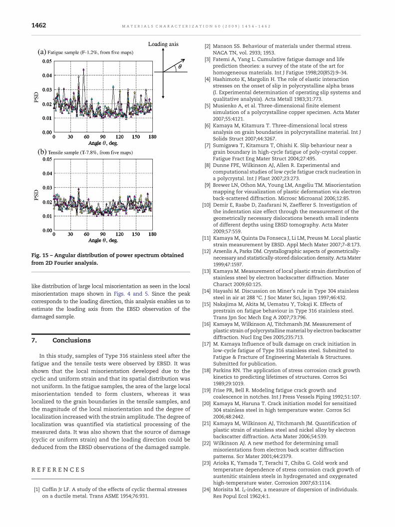
Fig. 15 – Angular distribution of power spectrum obtainedfrom 2D Fourier analysis.
1462 M A T E R I A L S C H A R A C T E R I Z A T I O N 6 0 ( 2 0 0 9 ) 1 4 5 4 – 1 4 6 2
like distribution of large local misorientation as seen in the localmisorientation maps shown in Figs. 4 and 5. Since the peakcorresponds to the loading direction, this analysis enables us toestimate the loading axis from the EBSD observation of thedamaged sample.
7. Conclusions
In this study, samples of Type 316 stainless steel after thefatigue and the tensile tests were observed by EBSD. It wasshown that the local misorientation developed due to thecyclic and uniform strain and that its spatial distribution wasnot uniform. In the fatigue samples, the area of the large localmisorientation tended to form clusters, whereas it waslocalized to the grain boundaries in the tensile samples, andthe magnitude of the local misorientation and the degree oflocalization increasedwith the strain amplitude. The degree oflocalization was quantified via statistical processing of themeasured data. It was also shown that the source of damage(cyclic or uniform strain) and the loading direction could bededuced from the EBSD observations of the damaged sample.
R E F E R E N C E S
[1] Coffin Jr LF. A study of the effects of cyclic thermal stresseson a ductile metal. Trans ASME 1954;76:931.
[2] Manson SS. Behaviour of materials under thermal stress.NACA TN, vol. 2933; 1953.
[3] Fatemi A, Yang L. Cumulative fatigue damage and lifeprediction theories: a survey of the state of the art forhomogeneous materials. Int J Fatigue 1998;20(852):9–34.
[4] Hashimoto K, Margolin H. The role of elastic interactionstresses on the onset of slip in polycrystalline alpha brass(I. Experimental determination of operating slip systems andqualitative analysis). Acta Metall 1983;31:773.
[5] Musienko A, et al. Three-dimensional finite elementsimulation of a polycrystalline copper specimen. Acta Mater2007;55:4121.
[6] Kamaya M, Kitamura T. Three-dimensional local stressanalysis on grain boundaries in polycrystalline material. Int JSolids Struct 2007;44:3267.
[7] Sumigawa T, Kitamura T, Ohishi K. Slip behaviour near agrain boundary in high-cycle fatigue of poly-crystal copper.Fatigue Fract Eng Mater Struct 2004;27:495.
[8] Dunne FPE, Wilkinson AJ, Allen R. Experimental andcomputational studies of low cycle fatigue crack nucleation ina polycrystal. Int J Plast 2007;23:273.
[9] Brewer LN, Othon MA, Young LM, Angeliu TM. Misorientationmapping for visualization of plastic deformation via electronback-scattered diffraction. Microsc Microanal 2006;12:85.
[10] Demir E, Raabe D, Zaafarani N, Zaefferer S. Investigation ofthe indentation size effect through the measurement of thegeometrically necessary dislocations beneath small indentsof different depths using EBSD tomography. Acta Mater2009;57:559.
[11] Kamaya M, Quinta Da Fonseca J, Li LM, Preuss M. Local plasticstrain measurement by EBSD. Appl Mech Mater 2007;7–8:173.
[12] Arsenlis A, Parks DM. Crystallographic aspects of geometrically-necessary and statistically-storeddislocationdensity. ActaMater1999;47:1597.
[13] KamayaM. Measurement of local plastic strain distribution ofstainless steel by electron backscatter diffraction. MaterCharact 2009;60:125.
[14] Hayashi M. Discussion on Miner's rule in Type 304 stainlesssteel in air at 288 °C. J Soc Mater Sci, Japan 1997;46:432.
[15] Nakajima M, Akita M, Uematsu Y, Tokaji K. Effects ofprestrain on fatigue behaviour in Type 316 stainless steel.Trans Jpn Soc Mech Eng A 2007;73:796.
[16] Kamaya M, Wilkinson AJ, Titchmarsh JM. Measurement ofplastic strain of polycrystallinematerial by electronbackscatterdiffraction. Nucl Eng Des 2005;235:713.
[17] M. Kamaya Influence of bulk damage on crack initiation inlow-cycle fatigue of Type 316 stainless steel. Submitted toFatigue & Fracture of Engineering Materials & Structures.Submitted for publication.
[18] Parkins RN. The application of stress corrosion crack growthkinetics to predicting lifetimes of structures. Corros Sci1989;29:1019.
[19] Frise PR, Bell R. Modeling fatigue crack growth andcoalescence in notches. Int J Press Vessels Piping 1992;51:107.
[20] Kamaya M, Haruna T. Crack initiation model for sensitized304 stainless steel in high temperature water. Corros Sci2006;48:2442.
[21] Kamaya M, Wilkinson AJ, Titchmarsh JM. Quantification ofplastic strain of stainless steel and nickel alloy by electronbackscatter diffraction. Acta Mater 2006;54:539.
[22] Wilkinson AJ. A new method for determining smallmisorientations from electron back scatter diffractionpatterns. Scr Mater 2001;44:2379.
[23] Arioka K, Yamada T, Terachi T, Chiba G. Cold work andtemperature dependence of stress corrosion crack growth ofaustenitic stainless steels in hydrogenated and oxygenatedhigh-temperature water. Corrosion 2007;63:1114.
[24] Morisita M. Iδ-index, a measure of dispersion of individuals.Res Popul Ecol 1962;4:1.


![Microstructural creep, fatigue and creep-fatigue modeling of ......modeling the response of metallic materials under di erent loading conditions [14] across di erent deformation mecha-nisms](https://img.pdfslide.net/doc/110x75/60deaa56f9a3fa7ea40f40c6/microstructural-creep-fatigue-and-creep-fatigue-modeling-of-modeling-the.jpg)