Embed Size (px)
Citation preview

EXAMPLE INTEGRATION INSTRUCTIONS
(WORK TICKET #) ASSEMBLY INSTRUCTIONS
Revision A
Effective May 12, 2005
Written By
Allan Sherman
Copy Number
N/A
Uncontrolled Copy
©2005 Chassis Plans, LLC 8295 Aero Place • Suite 200 • San Diego • California • 92123
Phone - 858-571-4330 Fax - 858-571-6146 • www.chassisplans.com

2
1) Remove ATX Rear Panel.
2) Install 14 Slot AT Rear Panel.
4) Install Power Supply with (4) Screws.
3
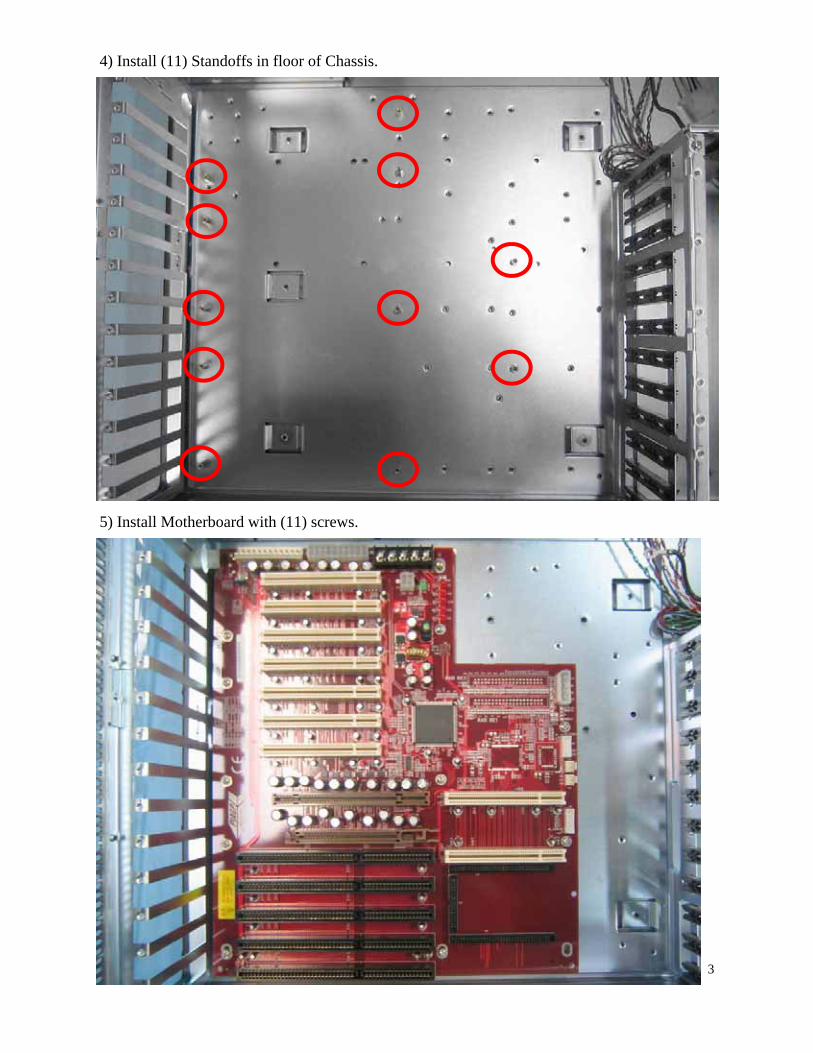
4) Install (11) Standoffs in floor of Chassis.
5) Install Motherboard with (11) screws.
4
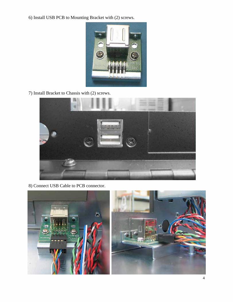
6) Install USB PCB to Mounting Bracket with (2) screws.
7) Install Bracket to Chassis with (2) screws.
8) Connect USB Cable to PCB connector.
5
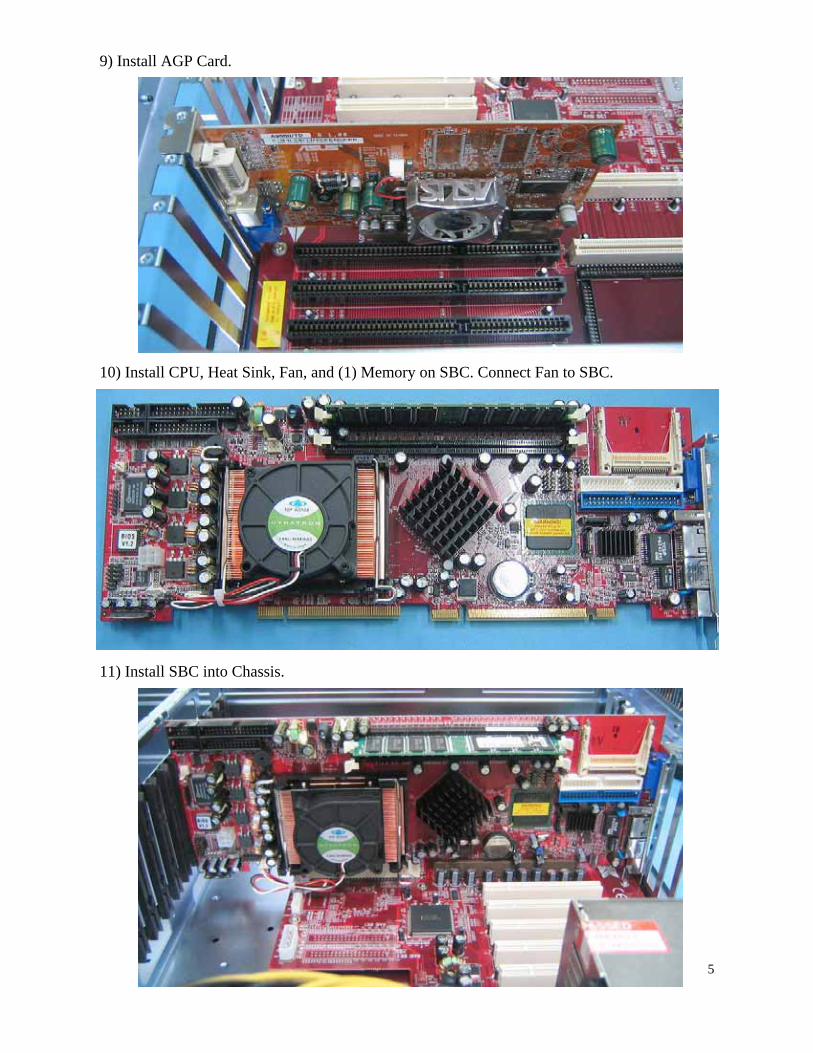
9) Install AGP Card.
10) Install CPU, Heat Sink, Fan, and (1) Memory on SBC. Connect Fan to SBC.
11) Install SBC into Chassis.

6
12) Install Audio, Serial, Parallel, and rear USB ports.
13) Re pin POWER LED by moving Green Wire from end to center position in connector.

7
14) Connect POWER LED, HDD LED, SPEAKER , & RESET SW to SBC.
15) Connect POWER SW and Serial Cables.

8
16) Connect Cable from Audio Ports to SBC.
17) Route USB Cables over SBC.
18) Connect USB Cables to SBC.
From Front USB Port
From Rear USB Ports

9
19) Apply RTV to Audio and Signal Cables.
20) Apply RTV to USB Cables.

10
21) Connect 12V Power Cable to SBC.
22) SBC Cabling.
23) Secure excess Cabling.

11
24) Connect Front Fan Cable to Drive Power Cable and secure Cables.
25) Connect ATX Power Cable. Secure Cables in front of Power Supply.
Do not use a cable anchor at this location

12
26) Connect SATA Cable to SBC.
27) Install GPIB Card.
28) Install Hard Drives into Removable Carriers.

13
29) Install CD and Hard Drive Carrier into Drive Cage.
30) Install Drive Cage Assembly, replacing the Rubber Mounts with Solid Brass Spacers.

14
31) Connect Cables to Drives.
32) Top view of Cable routing.

15
33) Place OS Label on front of Drive Cage. Place “Intel” insignia over unused hole in Front Panel.
34) Apply Chassis Plans Logo to front of Chassis.

16
35) Rear Panel of completed Chassis.
36) Adhere SN Label to bottom of Chassis.

17
37) Top view of completed Chassis.

18
ATK SET UP
BIOS
Load Optimized Defaults Advanced Bios Features: First Boot Device: Floppy Second Boot Device: CD Rom Third Boot Device: Hard Drive Boot up Numlock Status — ON
Advanced Chipset Features
On-Chip VGA—Disabled
Integrated Peripherals
Super IO Device Onboard FDC—Disable Note: To perform Microscope, FDC must be set to “Enabled”. Disable FDC before shipping.
PnP / PCI Configurations
PnP OS Installed—Yes