Embed Size (px)
Citation preview
CHECK METER
HJA-626, HJA-636, HJA-646
ISSUE 4.0
©2001 Universal Protection Corporation A Division of: H.J. Arnett Industries
Fourth Printing, October 2007
Universal Protection Corp./ H.J Arnett Industries 20460 SW Avery Ct, Tualatin, OR 97203
Table of Contents Check Meter Manual CM III & CNI 2X, 3X& 4X ITEM PAGE PRODUCT SUPPORT 1-1 INTRODUCTION 1-3 DESCRIPTION 2-1 TESTING CHECK METER 3-1 FIELD INSTALLATION 4-1 READING INSTALLED CHECK METER 5-1 FCC COMPLIANCE NOTIFICATION 6-1 MAINTENANCE 7-1 SPECIFICATIONS 8-1
WARRANTY UNIVERSAL PROTECTION CORP./ H.J. Arnett Industries, LLC warrants to the original purchaser of this product, to repair, or at our option, to replace if proven to be defective in workmanship or material under normal use for the period of 90 days from the date of purchase. Warranty does not cover accident, misuse, abuse or neglect on the part of the owner, and is void if product is disassembled or tampered with. THIS WARRANTY IS EXPRESSLY IN LIEU OF ALL OTHER WARRANTIES EXPRESSED OR IMPLIED INCLUDING THE WARRANTIES OF MERCHANTABILITY AND FITNESS FOR USE AND OF ALL OTHER OBLIGATIONS OR LIABILITIES ON OUR PART, AND WE NEITHER ASSUME, NOR AUTHORIZE ANY OTHER PERSON TO ASSUME FOR US, ANY OTHER LIABILITY IN CONNECTION .WITH THE SALE OF THIS PRODUCT. THIS WARRANTY SHALL NOT APPLY TO THIS PRODUCT OR ANY PART THEREOF WHICH HAS BEEN SUBJECT TO ACCIDENT, NEGLIGENCE, ALTERATION, ABUSE, OR MISUSE. WE MAKE NO WARRANTY WHATSOEVER IN RESPECT TO ACCESSORIES OR PARTS NOT SUPPLIED BY US. THIS WARRANTY SHALL APPLY ONLY WITHIN THE BOUNDARIES OF THE CONTINENTAL UNITED STATES. THIS WARRANTY GIVES YOU SPECIFIC LEGAL RIGHTS, AND YOU MAY ALSO HAVE OTHER RIGHTS WHICH VARY FROM STATE TO STATE. WARRANTY Product Support H.J. Arnett Industries 20460 SW Avery Ct Tualatin, OR 97203 503-692-4600 800-684-9844 Service available 7:30 AM to 4:30 PM Current Pacific Standard Time Monday thru Friday Emergency After Hours Service 800-684-9844
INTRODUCTION BACKGROUND As the price of electricity has increased, energy theft has become more lucrative. The incidence of pilfering, as well as major theft, increased dramatically in the 1980's. It is estimated that utilities are losing between 3 and 6% of their generated power to theft. Theft of electricity can be accomplished by tampering with the meter itself, using a substitute stolen meter for a portion of the billing period, or by tapping the service drop ahead of the meter so that the stolen electricity never goes through the meter at all. By installing a Check Meter at the serving distribution transformer, all of the electricity delivered to the customer is measured. If the thief is using a substitute meter during a portion of the month, inverting the billing meter so that it runs backwards, tampering with the dial pointers or the meter itself, or has an illegal tap, the check meter will record more energy consumption than the billing meter. The difference between the Check Meter reading and the billing meter reading is the amount of energy stolen. WHAT IS A CHECK METER? The Universal Protection Check Meter System consists of two modules, the CM III, a remote check meter and the CM Reader. The Check Meter (HJA-626/636/646) is a precision processor-based meter which measures the electric energy as accurately as the utility revenue meter. The reading of the energy measured is stored in the CM processor. Every 30 seconds a radio transmitter in the check meter is enabled and transmits the Check Meter ID #, the current kilowatt hour reading of the Check Meter and an operational status code. The CM Reader contains a radio receiver, processor to decode the radio signal and a LCD display. When the reader is activated within 500 feet of an operating check meter, the CM reader receives the transmitted signal from the Check Meter every 30 seconds. The receiver processor decodes the signal and displays the Meter Number, Meter Reading and the status code on the LCD display. The receiver is enabled with a surface-mounted membrane switch under the receiver label. When the "read" decal is pressed, the receiver is enabled for 4 minutes. Since the meter transmits its data for one second every 30 seconds, the reader will receive 7 or 8 transmissions and then automatically turn off. Press the "read" decal again to repeat the sequence. If the customer is using any power when the check meter is installed, the status code should advance 72 each 7.2 watthours used on a 200 Amp meter and 216 each 21.6 watthours used on a 600 Amp meter. The revenue meter may have a Kh of 14.4 to 57.6. The Kh is the meter's watthour measurement per disk revolution.
If the revenue meter has a Kh of 14.4, the status code on a 200 amp checkmeter will advance 144 per revolution of the revenue meter, or 72 per 1/2 disk revolution. If the revenue meter has a Kh of 14.4, the status code on a 600 amp checkmeter will advance 432 per 3 revolutions of the revenue meter. If the status code advances more than the calculated count, there is a high probability of a tap. DESCRIPTION The Check Meter consists of two modules, the processor-based solid state meter and the meter reader. CHECK METER The HJA-636/646 Check Meter is a Form 16, 3 element, polyphase, 4 wire 3 phase meter. The meter monitors the current with two or three clamp on CTs. The CTs are rated to 500 Amps. When supplied with 200 amp CTs, the checkmeter Kh is 7.2. When supplied with 500 amp CTs, the checkmeter Kh is 21.6. The Potential is picked up with the 4 potential clips. The green lead is ground, the meter electronics derives its voltage from the red clip. The red clip therefore, must always be connected and on a 4 wire delta service, must be connected to the high leg. The black and blue clips are the remaining two phases. On a 3 wire service only the blue, red and green leads are used. On a 4 wire service all 4 leads are used. The Clamp on CTs are each polarity identified with a red, black or blue dot. The polarity marks follow normal metering practice and are always mounted toward the (transformer) line side. On a 3 wire service only the CTs with the red and blue polarity mark are used. On a 4 wire service all three CT's are used. The color code also identifies how to connect the potential clips for the correct polarity. The meter is calibrated as a system with its own Clamp on CTs to insure overall system accuracy. The meter serial number is factory programmed; the accumulated KWH are stored in a non-volatile memory and can only be reset to zero at the factory; the operational status code is incremented 72 counts [7.2 watthours] per "disk revolution" on a 200 amp meter and 216 counts
HJA-626/636/646 Check Meter
[21.6 watthours] per "disk revolution" on a 500 amp meter. The status code is also stored in the non-volatile memory. The Check Meter is factory calibrated to +/-.5% accuracy with its own Clamp on CTs. The Check Meter with 200 amp CTs is calibrated at the traditional test points for a 200 amp meter, 30 amps for full load and power factor and 3 amps for light load. The check meter with 500 amp CTs is calibrated at 90 amps for full load and power factor and 9 amps for light load. The load curve from 1 amp to 200 amps or 9 amps to 500 amps is within +/-.5% of reading. Once calibrated, barring component failure, the Check Meter will maintain its accuracy. The Check Meter has a "window" on its face for detecting the output from an internal infrared light emitting diode. The infrared is not visible to the human eye. The light emitting diode is pulsed each "equivalent disk revolution" 7.2 watt hours for 200 Amp meters and 21.6 watt hours for 500 amp meters. The meter's accuracy can be verified with a normal Utility Meter Test Board with a solid state pickup. The test board's electronic pickup is placed above the meter "window". The meter accuracy can be verified with the test board using the same procedures used to verify a revenue meter. The Check Meter is mounted in a sealed waterproof enclosure. Rubber gaskets seal the cover, mounting screws and cable entrance fixture. The cable entrance is filled with silicone. The entire meter is submersible and under normal circumstances, will not leak.
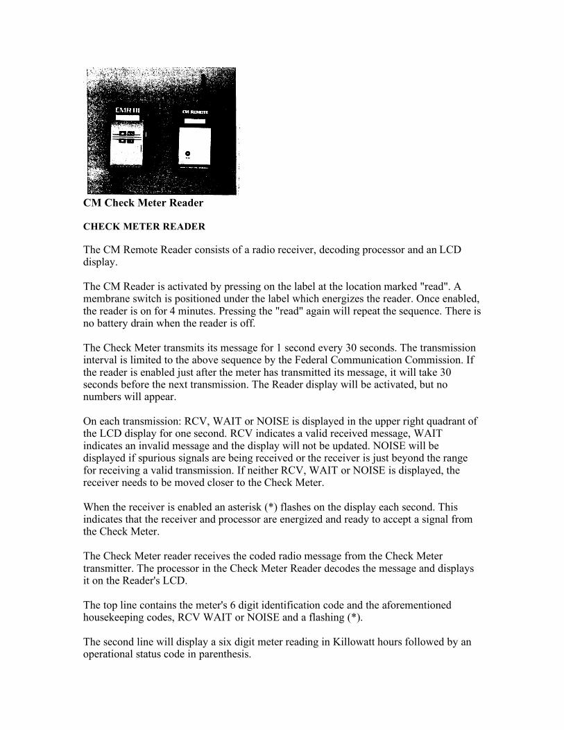
CM Check Meter Reader CHECK METER READER The CM Remote Reader consists of a radio receiver, decoding processor and an LCD display. The CM Reader is activated by pressing on the label at the location marked "read". A membrane switch is positioned under the label which energizes the reader. Once enabled, the reader is on for 4 minutes. Pressing the "read" again will repeat the sequence. There is no battery drain when the reader is off. The Check Meter transmits its message for 1 second every 30 seconds. The transmission interval is limited to the above sequence by the Federal Communication Commission. If the reader is enabled just after the meter has transmitted its message, it will take 30 seconds before the next transmission. The Reader display will be activated, but no numbers will appear. On each transmission: RCV, WAIT or NOISE is displayed in the upper right quadrant of the LCD display for one second. RCV indicates a valid received message, WAIT indicates an invalid message and the display will not be updated. NOISE will be displayed if spurious signals are being received or the receiver is just beyond the range for receiving a valid transmission. If neither RCV, WAIT or NOISE is displayed, the receiver needs to be moved closer to the Check Meter. When the receiver is enabled an asterisk (*) flashes on the display each second. This indicates that the receiver and processor are energized and ready to accept a signal from the Check Meter. The Check Meter reader receives the coded radio message from the Check Meter transmitter. The processor in the Check Meter Reader decodes the message and displays it on the Reader's LCD. The top line contains the meter's 6 digit identification code and the aforementioned housekeeping codes, RCV WAIT or NOISE and a flashing (*). The second line will display a six digit meter reading in Killowatt hours followed by an operational status code in parenthesis.
The operational status code is actually tenths of watthours. Since the meter output is watthours per disk revolution, and the meter Kh is 7.2 or 21.6 watthours per revolution, the status code is incremented by 72 or 216 for each equivalent disk revolution, i.e., the status code will increment 0072, 0144 . . . 0936 or 0216, 0432, etc. This status code makes it very easy to verify the correct installation of the Check Meter. If the status code is not incremented, and the customer's meter is running, the polarity of the CT's and/or potential connections are not correct. The Check Meter is "detented" and can not run backwards. When the Check Meter is enabled the display will look like:
UPC Check Meter v 1.5 930600
This is the revision level of the receiver software and the date of the revision August 25, 1994. This message will be followed by:
(C) 1994 UPC All rights reserved
This message will be followed by:
ID: ----- * MR: ----- (----)
This message will be followed by the meter reading, i.e.:
ID: 930600 MR: 000014 (0072)
This would be interpreted as meter number 930600, Kwhr reading of 14 and status code of 72.
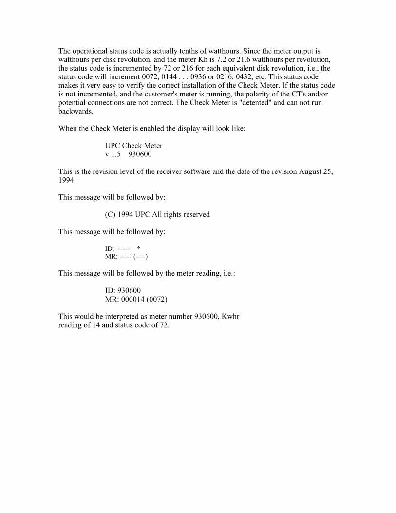
TESTING CHECK METER Note: Check Meter is not to be opened by anyone other than factory personnel. All calibration is accomplished in software and there are no user adjustments inside the CM box. Board Test on Check Meter Note: Must have a board equipped with an Electronic Pickup for Solid State Meters. 1. Insert a socket adaptor with a buss bar from the line to load terminals in the board socket.
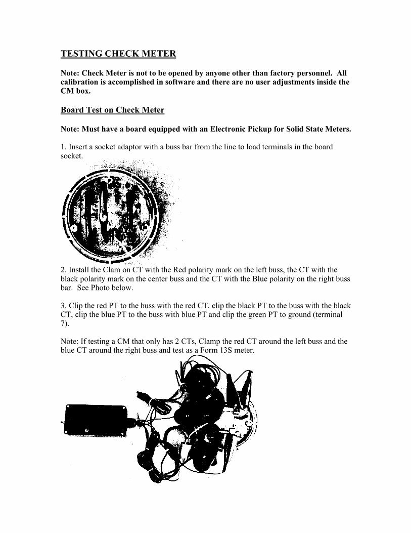
2. Install the Clam on CT with the Red polarity mark on the left buss, the CT with the black polarity mark on the center buss and the CT with the Blue polarity on the right buss bar. See Photo below.
3. Clip the red PT to the buss with the red CT, clip the black PT to the buss with the black CT, clip the blue PT to the buss with blue PT and clip the green PT to ground (terminal 7). Note: If testing a CM that only has 2 CTs, Clamp the red CT around the left buss and the blue CT around the right buss and test as a Form 13S meter.
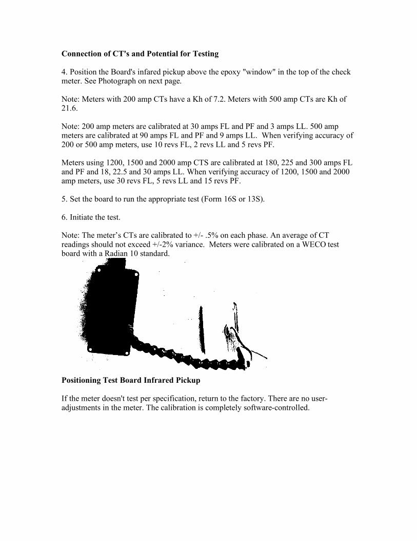
Connection of CT's and Potential for Testing 4. Position the Board's infared pickup above the epoxy "window" in the top of the check meter. See Photograph on next page. Note: Meters with 200 amp CTs have a Kh of 7.2. Meters with 500 amp CTs are Kh of 21.6. Note: 200 amp meters are calibrated at 30 amps FL and PF and 3 amps LL. 500 amp meters are calibrated at 90 amps FL and PF and 9 amps LL. When verifying accuracy of 200 or 500 amp meters, use 10 revs FL, 2 revs LL and 5 revs PF. Meters using 1200, 1500 and 2000 amp CTS are calibrated at 180, 225 and 300 amps FL and PF and 18, 22.5 and 30 amps LL. When verifying accuracy of 1200, 1500 and 2000 amp meters, use 30 revs FL, 5 revs LL and 15 revs PF. 5. Set the board to run the appropriate test (Form 16S or 13S). 6. Initiate the test. Note: The meter’s CTs are calibrated to +/- .5% on each phase. An average of CT readings should not exceed +/-2% variance. Meters were calibrated on a WECO test board with a Radian 10 standard.
Positioning Test Board Infrared Pickup If the meter doesn't test per specification, return to the factory. There are no user-adjustments in the meter. The calibration is completely software-controlled.
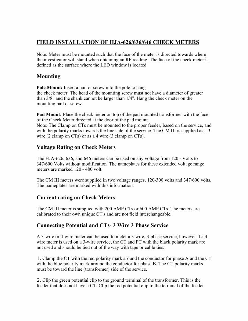
FIELD INSTALLATION OF HJA-626/636/646 CHECK METERS Note: Meter must be mounted such that the face of the meter is directed towards where the investigator will stand when obtaining an RF reading. The face of the check meter is defined as the surface where the LED window is located. Mounting Pole Mount: Insert a nail or screw into the pole to hang the check meter. The head of the mounting screw must not have a diameter of greater than 3/8" and the shank cannot be larger than 1/4". Hang the check meter on the mounting nail or screw. Pad Mount: Place the check meter on top of the pad mounted transformer with the face of the Check Meter directed at the door of the pad mount. Note: The Clamp on CTs must be mounted to the proper feeder, based on the service, and with the polarity marks towards the line side of the service. The CM III is supplied as a 3 wire (2 clamp on CTs) or as a 4 wire (3 clamp on CTs). Voltage Rating on Check Meters The HJA-626, 636, and 646 meters can be used on any voltage from 120 - Volts to 347/600 Volts without modification. The nameplates for these extended voltage range meters are marked 120 - 480 volt. The CM III meters were supplied in two voltage ranges, 120-300 volts and 347/600 volts. The nameplates are marked with this information. Current rating on Check Meters The CM III meter is supplied with 200 AMP CTs or 600 AMP CTs. The meters are calibrated to their own unique CT's and are not field interchangeable. Connecting Potential and CTs- 3 Wire 3 Phase Service A 3-wire or 4-wire meter can be used to meter a 3-wire, 3-phase service, however if a 4-wire meter is used on a 3-wire service, the CT and PT with the black polarity mark are not used and should be tied out of the way with tape or cable ties. 1. Clamp the CT with the red polarity mark around the conductor for phase A and the CT with the blue polarity mark around the conductor for phase B. The CT polarity marks must be toward the line (transformer) side of the service. 2. Clip the green potential clip to the ground terminal of the transformer. This is the feeder that does not have a CT. Clip the red potential clip to the terminal of the feeder
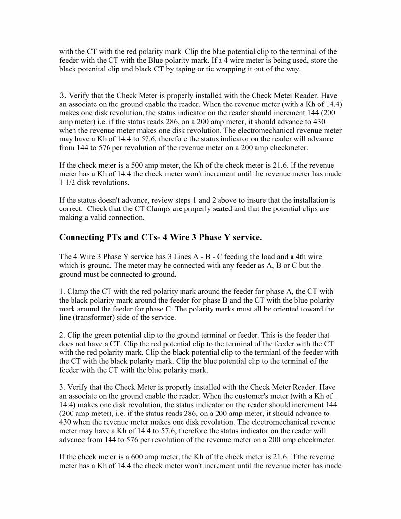
with the CT with the red polarity mark. Clip the blue potential clip to the terminal of the feeder with the CT with the Blue polarity mark. If a 4 wire meter is being used, store the black potenital clip and black CT by taping or tie wrapping it out of the way. 3. Verify that the Check Meter is properly installed with the Check Meter Reader. Have an associate on the ground enable the reader. When the revenue meter (with a Kh of 14.4) makes one disk revolution, the status indicator on the reader should increment 144 (200 amp meter) i.e. if the status reads 286, on a 200 amp meter, it should advance to 430 when the revenue meter makes one disk revolution. The electromechanical revenue meter may have a Kh of 14.4 to 57.6, therefore the status indicator on the reader will advance from 144 to 576 per revolution of the revenue meter on a 200 amp checkmeter. If the check meter is a 500 amp meter, the Kh of the check meter is 21.6. If the revenue meter has a Kh of 14.4 the check meter won't increment until the revenue meter has made 1 1/2 disk revolutions. If the status doesn't advance, review steps 1 and 2 above to insure that the installation is correct. Check that the CT Clamps are properly seated and that the potential clips are making a valid connection. Connecting PTs and CTs- 4 Wire 3 Phase Y service. The 4 Wire 3 Phase Y service has 3 Lines A - B - C feeding the load and a 4th wire which is ground. The meter may be connected with any feeder as A, B or C but the ground must be connected to ground. 1. Clamp the CT with the red polarity mark around the feeder for phase A, the CT with the black polarity mark around the feeder for phase B and the CT with the blue polarity mark around the feeder for phase C. The polarity marks must all be oriented toward the line (transformer) side of the service. 2. Clip the green potential clip to the ground terminal or feeder. This is the feeder that does not have a CT. Clip the red potential clip to the terminal of the feeder with the CT with the red polarity mark. Clip the black potential clip to the termianl of the feeder with the CT with the black polarity mark. Clip the blue potential clip to the terminal of the feeder with the CT with the blue polarity mark. 3. Verify that the Check Meter is properly installed with the Check Meter Reader. Have an associate on the ground enable the reader. When the customer's meter (with a Kh of 14.4) makes one disk revolution, the status indicator on the reader should increment 144 (200 amp meter), i.e. if the status reads 286, on a 200 amp meter, it should advance to 430 when the revenue meter makes one disk revolution. The electromechanical revenue meter may have a Kh of 14.4 to 57.6, therefore the status indicator on the reader will advance from 144 to 576 per revolution of the revenue meter on a 200 amp checkmeter. If the check meter is a 600 amp meter, the Kh of the check meter is 21.6. If the revenue meter has a Kh of 14.4 the check meter won't increment until the revenue meter has made
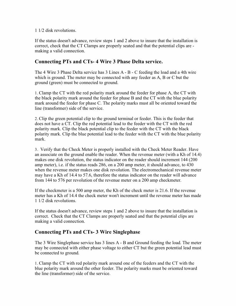
1 1/2 disk revolutions. If the status doesn't advance, review steps 1 and 2 above to insure that the installation is correct, check that the CT Clamps are properly seated and that the potential clips are - making a valid connection. Connecting PTs and CTs- 4 Wire 3 Phase Delta service. The 4 Wire 3 Phase Delta service has 3 Lines A - B - C feeding the load and a 4th wire which is ground. The meter may be connected with any feeder as A, B or C but the ground (green) must be connected to ground. 1. Clamp the CT with the red polarity mark around the feeder for phase A, the CT with the black polarity mark around the feeder for phase B and the CT with the blue polarity mark around the feeder for phase C. The polarity marks must all be oriented toward the line (transformer) side of the service. 2. Clip the green potential clip to the ground terminal or feeder. This is the feeder that does not have a CT. Clip the red potential lead to the feeder with the CT with the red polarity mark. Clip the black potential clip to the feeder with the CT with the black polarity mark. Clip the blue potential lead to the feeder with the CT with the blue polarity mark. 3. Verify that the Check Meter is properly installed with the Check Meter Reader. Have an associate on the ground enable the reader. When the revenue meter (with a Kh of 14.4) makes one disk revolution, the status indicator on the reader should increment 144 (200 amp meter), i.e. if the status reads 286, on a 200 amp meter, it should advance, to 430 when the revenue meter makes one disk revolution. The electromechanical revenue meter may have a Kh of 14.4 to 57.6, therefore the status indicator on the reader will advance from 144 to 576 per revolution of the revenue meter on a 200 amp checkmeter. If the checkmeter is a 500 amp meter, the Kh of the check meter is 21.6. If the revenue meter has a Kh of 14.4 the check meter won't increment until the revenue meter has made 1 1/2 disk revolutions. If the status doesn't advance, review steps 1 and 2 above to insure that the installation is correct. Check that the CT Clamps are properly seated and that the potential clips are making a valid connection. Connecting PTs and CTs- 3 Wire Singlephase The 3 Wire Singlephase service has 3 lines A - B and Ground feeding the load. The meter may be connected with either phase voltage to either CT but the green potential lead must be connected to ground. 1. Clamp the CT with red polarity mark around one of the feeders and the CT with the blue polarity mark around the other feeder. The polarity marks must be oriented toward the line (transformer) side of the service.
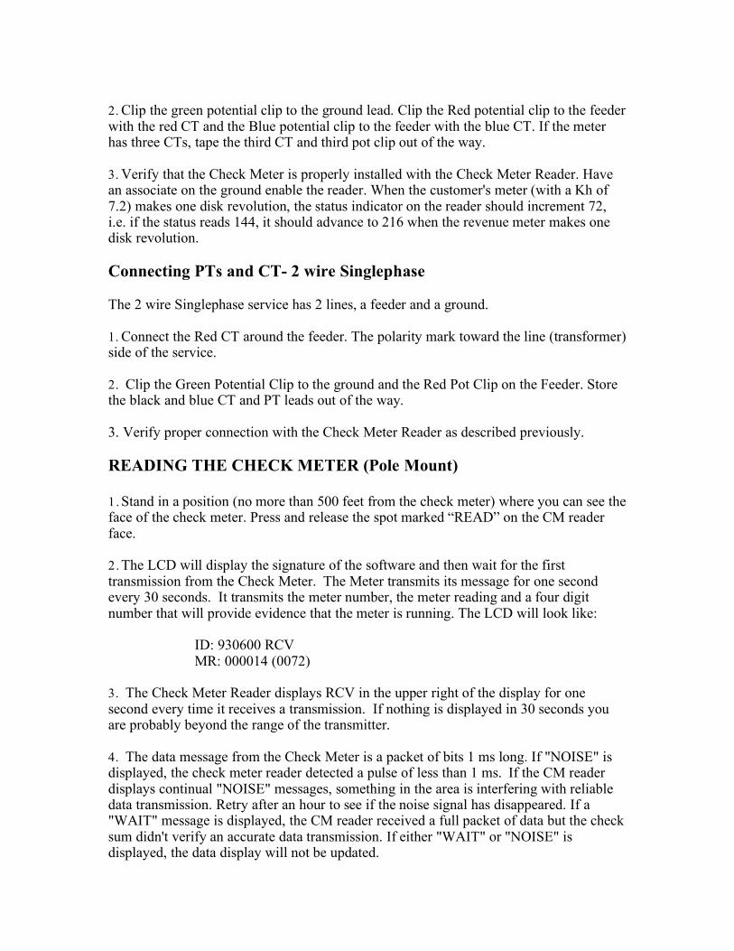
2. Clip the green potential clip to the ground lead. Clip the Red potential clip to the feeder with the red CT and the Blue potential clip to the feeder with the blue CT. If the meter has three CTs, tape the third CT and third pot clip out of the way. 3. Verify that the Check Meter is properly installed with the Check Meter Reader. Have an associate on the ground enable the reader. When the customer's meter (with a Kh of 7.2) makes one disk revolution, the status indicator on the reader should increment 72, i.e. if the status reads 144, it should advance to 216 when the revenue meter makes one disk revolution. Connecting PTs and CT- 2 wire Singlephase The 2 wire Singlephase service has 2 lines, a feeder and a ground. 1. Connect the Red CT around the feeder. The polarity mark toward the line (transformer) side of the service. 2. Clip the Green Potential Clip to the ground and the Red Pot Clip on the Feeder. Store the black and blue CT and PT leads out of the way. 3. Verify proper connection with the Check Meter Reader as described previously. READING THE CHECK METER (Pole Mount) 1. Stand in a position (no more than 500 feet from the check meter) where you can see the face of the check meter. Press and release the spot marked “READ” on the CM reader face. 2 . The LCD will display the signature of the software and then wait for the first transmission from the Check Meter. The Meter transmits its message for one second every 30 seconds. It transmits the meter number, the meter reading and a four digit number that will provide evidence that the meter is running. The LCD will look like:
ID: 930600 RCV MR: 000014 (0072)
3. The Check Meter Reader displays RCV in the upper right of the display for one second every time it receives a transmission. If nothing is displayed in 30 seconds you are probably beyond the range of the transmitter. 4. The data message from the Check Meter is a packet of bits 1 ms long. If "NOISE" is displayed, the check meter reader detected a pulse of less than 1 ms. If the CM reader displays continual "NOISE" messages, something in the area is interfering with reliable data transmission. Retry after an hour to see if the noise signal has disappeared. If a "WAIT" message is displayed, the CM reader received a full packet of data but the check sum didn't verify an accurate data transmission. If either "WAIT" or "NOISE" is displayed, the data display will not be updated.
5. The Check Meter Reader will remain on for 4 minutes and then automatically turn off. If you have not completed your reading, press the read button to initiate another 4 minutes of reception. 6. The display will remain constant as long there is no change on each repeated transmission. The four digit number in the brackets at the lower right of the display will increment when 7.2 watt hours is accumulated. This is equivalent to one disk revolution of an electromechanical meter with a Kh of 7.2. The status display will read 72 after the first 7.2 watt hours, 144 after the second 7.2 watt hours, etc. READING CHECK METER TRANSFORMER (Pedestal) If the Transformer Pedestal is steel, the steel will attenuate the radio signal from the Check Meter. It is sometimes necessary to be within 10 feet of the pad mount enclosure to read the Check Meter. Normally a reading can be obtained without opening the pad mount door. Follow procedures outlined in previous section.
FCC REGULATIONS Warning: Changes or modifications to this unit not expressly approved by the party responsible for compliance could void the user's authority to operate this equipment. Note: This equipment has been tested and found to comply with the limits for a Class B digital device, pursuant to Part 15 of the FCC Rules. These limits are designed to provide reasonable protection against harmful interference in a residential installation. This equipment generates, uses and can radiate radio frequency energy and, if not installed and used in accordance with the instructions, may cause harmful interference to radio communications. However, there is no guarantee that interference will not occur in a particular installation. If the equipment does cause harmful interference to radio or television reception, which can be determined by turning the equipment off and on, the user is encouraged to try to correct the interference by one or more of the following measures: * Reorient the Check Meter so that the transmit antenna is not pointing directly at the customer's house. * Consult H.J Arnett Industries for assistance.
MAINTENANCE Low Battery Processor - When the batteries have insufficient power to reliably operate the Check Meter Reader, the message "Low Batt" will be displayed on the LCD. The Check Meter Reader will continue to operate for some period of time following display of the “Low Batt” indication. See section below for replacing batteries. Low Battery Radio Receiver There are 4 Batteries in the Check Meter Reader. The lower two power the decoder electronics and those two plus two others power the radio receiver. The drain on the lower pair is 30 ma and the drain on the upper pair is 10 ma. Batteries will operate successfully down to 2.6 volts on a 50 ma load. To test the batteries, measure the battery voltage with a 50 ohm load resistor connected to the terminals. If the voltage is 2.6 or higher the batteries will operate. A new battery will normally measure 2.9 volts with a 50 ohm load. Temperature effect on battery performance - Lithium battery performance is affected by ambient temperature. When approximately 1/2 of the battery energy has been consumed, the battery voltage when operated at less than 50 degrees F may fall below the operating threshold of the Check Meter. Warming the Check Meter Reader to 70 degrees will probably allow the unit to function again. There is no permanent damage to the Check Meter Reader or the batteries by temperatures down to 0 degrees F. Replacing Batteries - To replace batteries, remove the 4 outer-most case screws and remove the CM Reader cover. Carefully remove the old batteries. The batteries are held in the holders by friction. Only use identical batteries for replacement. (BR 2/3A Lithium) Replacement batteries are available from H.J. Arnett Industries. Replace cover and re-secure with four case screws. Adjusting contrast on LCD display - The circuitry in the Check Meter Reader maintains a constant voltage to the display therefore the contrast should be constant. If you want a lighter or darker display remove the 4 outer-most case screws and remove the CM Reader cover. There is a small pot located on the board above the display. Using a small screw driver, rotate the pot Clockwise or Counter-clockwise until the desired contrast is obtained. Replace cover and re-secure with four case screws. Other adjustments on Check Meter Reader The only adjustment on the CM Reader is the contrast. There are no other user adjustments. Adjustments on the CM III Meter - There are no adjustments on the Check Meter. Calibration of the meter is completely software controlled. The Check Meter cover, cable entrance fitting and case screws are all gasketed. Opening of the Check Meter will destroy the integrity of the gaskets and void the warranty. Repair and/or calibration of the Check Meter must be performed at the factory. Verifying meter accuracy is performed by "viewing" the 'infrared LED through the "window". The infared output is invisible to the human eye. Care of Clamp on CT Core - The CT interlocking core must be kept clean to insure metering accuracy. If necessary, clean the core face with a very fine steel wool. Surface can be somewhat protected with a light spray of Silicone. Wipe excess off core to insure

a tight interface between the core faces. Any spacing between the cores will introduce metering errors. If the core faces become too degraded, it will be necessary to replace the CT's and recalibrate the meter. This is a factory repair only.
CM III Check Meter SPECIFICATIONS Form 16: Polyphase, 4 wire
Kh 7.2 on 200 Amp Kh 21.6 on 500 Amp
Voltage: 120 to 600 Volt Auto ranging Electronics derive voltage from red pot clip and green pot clip.
Current: 1 to 200 Amps Sensed by three Fluke Clamp on CTs. Up to 500 Amp
sensed by Fluke Clamp on CTs. Meter calibrated with its own CTs to ensure accuracy.
Temperature: Meter will be within +/- 1% over temperature range of -40 degrees C to
+85 degrees C. Load Curve @ 25 degrees C: +/- .5% from 1 to 200 Amperes or 9 to 600 Amperes using
500 Amp CTs. Submersible: Meter is gasketed at cable entrance fixture, enclosure seam, mounting
bracket connection and case screws. Calibration Accuracy certification: Internal Infrared LEDis pulsed once per 7.2 watthours
(200.Amp CTs) and once per 21.6 watthours (600 Amp CTs). LED can be monitored with an' Infrared Detector placed over the Epoxy "window" in the meter face. This can be tested with a normal watthour meter test board with an electronic pickup.
Test procedure: Same as for testing electromechanical form 16S (4 wire) or 13S (3 wire)
meters. Mounting Bracket: Polycarbonate bracket with Key slot. Internal Radio Transmitter: Transmits the meter serial #, meter reading and an
operational status code for 1 second, every 30 seconds. Radio is FCC and IC certified.
Check Meter Reader Reader contains a Radio receiver, processor for decoding received signal and an LCD display. Batteries: 4 - 2/3A 3.0 volt Lithium. Temperature: Batteries need to be above 50 degrees F to provide satisfactory
performance. Batteries will not be damaged at 0 degrees F and will return to normal performance when brought back to 50 degrees F.
On/Off: Press the "Read" position on the Check Meter Reader face plate. Reader
will be enabled for 4 minutes and automatically turn off. Radio Receiver: FCC and IC Certified. LOW BATT: Displayed when the batteries should be replaced. Reader will continue to
function for a period of time after LOW BATT has been displayed. Batteries will perform satisfactorily @ 2.6 volts on a 50 ma load. If under this test the battery voltage is below 2.6 volts, replace batteries.