Embed Size (px)
Citation preview
Check Point QoSAdministration Guide
Version R70
700726 February 26, 2009

© 2003-2009 Check Point Software Technologies Ltd.
All rights reserved. This product and related documentation are protected by copyright and distributed under licensing restricting their use, copying, distribution, and decompilation. No part of this product or related documentation may be reproduced in any form or by any means without prior written authorization of Check Point. While every precaution has been taken in the preparation of this book, Check Point assumes no responsibility for errors or omissions. This publication and features described herein are subject to change without notice.
RESTRICTED RIGHTS LEGEND:
Use, duplication, or disclosure by the government is subject to restrictions as set forth in subparagraph (c)(1)(ii) of the Rights in Technical Data and Computer Software clause at DFARS 252.227-7013 and FAR 52.227-19.
TRADEMARKS:
Please refer to http://www.checkpoint.com/copyright.html for a list of our trademarks
For third party notices, see http://www.checkpoint.com/3rd_party_copyright.html.

Table of Contents 5
Contents
Preface Who Should Use This Guide.............................................................................. 10Summary of Contents ....................................................................................... 11
Appendices ................................................................................................ 11Related Documentation .................................................................................... 12More Information ............................................................................................. 14Feedback ........................................................................................................ 15
Chapter 1 Overview What is Quality of Service................................................................................. 18Bandwidth Management Technologies ............................................................... 19
Overview .................................................................................................... 19Superior QoS Solution Requirements ............................................................ 19Benefits of a Policy-Based Solution .............................................................. 20
How Does Check Point Deliver QoS.................................................................... 21Features and Benefits ...................................................................................... 23Traditional QoS vs. QoS Express........................................................................ 24Workflow......................................................................................................... 26
Chapter 2 Introduction to QoS QoS’s Innovative Technology............................................................................. 28
Technology Overview ................................................................................... 29QoS Architecture ............................................................................................. 31
Basic Architecture ...................................................................................... 31QoS Configuration....................................................................................... 33Concurrent Sessions.................................................................................... 36
Interaction with VPN-1..................................................................................... 37Interoperability ........................................................................................... 37
Chapter 3 Basic Policy Management Overview ......................................................................................................... 40Rule Base Management.................................................................................... 41
Overview .................................................................................................... 41Connection Classification............................................................................. 42Network Objects ......................................................................................... 42Services and Resources ............................................................................... 43Time Objects.............................................................................................. 43Bandwidth Allocation and Rules ................................................................... 43Default Rule............................................................................................... 45QoS Action Properties ................................................................................. 45Example of a Rule Matching VPN Traffic....................................................... 46Bandwidth Allocation and Sub-Rules ............................................................ 47
6
Implementing the Rule Base............................................................................. 49To Verify and View the QoS Policy ................................................................ 49To Install and Enforce the Policy .................................................................. 49To Uninstall the QoS Policy ......................................................................... 50To Monitor the QoS Policy ........................................................................... 50
Chapter 4 QoS Tutorial Introduction .................................................................................................... 52Building and Installing a QoS Policy .................................................................. 53
Installing Check Point Gateways................................................................... 54Starting SmartDashboard............................................................................. 54Defining the Services .................................................................................. 69Creating a Rule Base................................................................................... 69Installing a QoS Policy ................................................................................ 77
Conclusion ...................................................................................................... 79
Chapter 5 Advanced QoS Policy Management Overview ......................................................................................................... 82Examples: Guarantees and Limits...................................................................... 83
Per Rule Guarantees ................................................................................... 83Per Connections Guarantees ........................................................................ 86Limits........................................................................................................ 87Guarantee - Limit Interaction ....................................................................... 87
Differentiated Services (DiffServ) ...................................................................... 89Overview .................................................................................................... 89DiffServ Markings for IPSec Packets ............................................................. 89Interaction Between DiffServ Rules and Other Rules ...................................... 90
Low Latency Queuing ....................................................................................... 91Overview .................................................................................................... 91Low Latency Classes ................................................................................... 91Interaction between Low Latency and Other Rule Properties............................ 96When to Use Low Latency Queuing............................................................... 97Low Latency versus DiffServ......................................................................... 98
Authenticated QoS........................................................................................... 99Citrix MetaFrame Support............................................................................... 100
Overview .................................................................................................. 100Limitations............................................................................................... 101
Load Sharing................................................................................................. 102Overview .................................................................................................. 102QoS Cluster Infrastructure ......................................................................... 103
Chapter 6 Managing QoS Defining QoS Global Properties ....................................................................... 108
To Modify the QoS Global Properties........................................................... 108Specifying Interface QoS Properties................................................................. 110
To Define the Interface QoS Properties ....................................................... 110Editing QoS Rule Bases.................................................................................. 114
Table of Contents 7
To Create a New Policy Package ................................................................. 114To Open an Existing Policy Package............................................................ 115To Add a Rule Base .................................................................................. 115To Rename a Rule .................................................................................... 117To Copy, Cut or Paste a Rule...................................................................... 117To Delete a Rule ....................................................................................... 118
Modifying Rules............................................................................................. 119Modifying Sources in a Rule ...................................................................... 119Modifying Destinations in a Rule ................................................................ 122Modifying Services in a Rule ...................................................................... 124Modifying Rule Actions.............................................................................. 126Modifying Tracking for a Rule .................................................................... 131Modifying Install On for a Rule................................................................... 131Modifying Time in a Rule........................................................................... 134Adding Comments to a Rule....................................................................... 136
Defining Sub-Rules........................................................................................ 138Working with Differentiated Services (DiffServ) ................................................. 140
To Define a DiffServ Class of Service .......................................................... 141To Define a DiffServ Class of Service Group................................................. 142To Add QoS Class Properties for Expedited Forwarding ................................. 143To Add QoS Class Properties for Non Expedited Forwarding .......................... 144
Working with Low Latency Classes................................................................... 146To Implement Low Latency Queuing ........................................................... 146To Define Low Latency Classes of Service.................................................... 147To Define Class of Service Properties for Low Latency Queuing...................... 147
Working with Authenticated QoS ..................................................................... 149To Use Authenticated QoS......................................................................... 149
Managing QoS for Citrix ICA Applications ......................................................... 151Disabling Session Sharing.......................................................................... 151Modifying your Security Policy ................................................................... 152Discovering Citrix ICA Application Names.................................................... 152Defining a New Citrix TCP Service .............................................................. 155Adding a Citrix TCP Service to a Rule (Traditional Mode Only)....................... 156Installing the Security and QoS Policies ...................................................... 156
Managing QoS for Citrix Printing ..................................................................... 157Configuring a Citrix Printing Rule (Traditional Mode Only)............................. 157Configuring QoS Topology .......................................................................... 158
Viewing QoS Gateway Status ........................................................................... 159Display QoS Gateways Controlled by SmartCenter......................................... 159
Enabling Log Collection.................................................................................. 160To Turn on QoS Logging ............................................................................ 160To Confirm that the Rule is Marked for Logging ........................................... 161To Start SmartView Tracker........................................................................ 162
Chapter 7 SmartView Tracker Overview of Logging ....................................................................................... 164Examples of Log Events.................................................................................. 168
Connection Reject Log .............................................................................. 168
8
LLQ Drop Log ........................................................................................... 168Pool Exceeded Log.................................................................................... 169
Examples of Account Statistics Logs................................................................ 171General Statistics Data.............................................................................. 171Drop Policy Statistics Data......................................................................... 172LLQ Statistics Data ................................................................................... 172
Chapter 8 Command Line Interface QoS Commands ............................................................................................. 174Setup ........................................................................................................... 175fgate Menu ................................................................................................... 176Control ......................................................................................................... 177Monitor......................................................................................................... 179Utilities ........................................................................................................ 181
Chapter 9 FAQ Introduction ............................................................................................. 183QoS Basics............................................................................................... 184Other Check Point Products - Support and Management ............................... 187Policy Creation ......................................................................................... 188Capacity Planning..................................................................................... 189Protocol Support....................................................................................... 190Installation/Backward Compatibility/Licensing/Versions................................. 190How do I? ................................................................................................ 191General Issues.......................................................................................... 192
Chapter 10 Deploying QoS Deploying QoS............................................................................................... 196
QoS Topology Restrictions ......................................................................... 196Sample Bandwidth Allocations........................................................................ 198
Frame Relay Network ................................................................................ 198
Appendix A Debug Flags fw ctl debug -m FG-1 Error Codes for QoS........................................................ 202
9
Preface PPreface
In This Chapter
Who Should Use This Guide page 10
Summary of Contents page 11
Related Documentation page 12
More Information page 14
Feedback page 15
Who Should Use This Guide
10
Who Should Use This GuideThis guide is intended for administrators responsible for maintaining network security within an enterprise, including policy management and user support.
This guide assumes a basic understanding of
• System administration.
• The underlying operating system.
• Internet protocols (IP, TCP, UDP etc.).
Summary of Contents
Preface 11
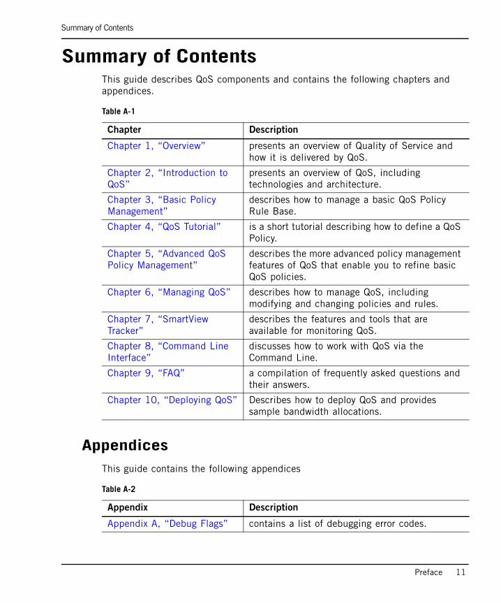
Summary of ContentsThis guide describes QoS components and contains the following chapters and appendices.
AppendicesThis guide contains the following appendices
Table A-1
Chapter Description
Chapter 1, “Overview” presents an overview of Quality of Service and how it is delivered by QoS.
Chapter 2, “Introduction to QoS”
presents an overview of QoS, including technologies and architecture.
Chapter 3, “Basic Policy Management”
describes how to manage a basic QoS Policy Rule Base.
Chapter 4, “QoS Tutorial” is a short tutorial describing how to define a QoS Policy.
Chapter 5, “Advanced QoS Policy Management”
describes the more advanced policy management features of QoS that enable you to refine basic QoS policies.
Chapter 6, “Managing QoS” describes how to manage QoS, including modifying and changing policies and rules.
Chapter 7, “SmartView Tracker”
describes the features and tools that are available for monitoring QoS.
Chapter 8, “Command Line Interface”
discusses how to work with QoS via the Command Line.
Chapter 9, “FAQ” a compilation of frequently asked questions and their answers.
Chapter 10, “Deploying QoS” Describes how to deploy QoS and provides sample bandwidth allocations.
Table A-2
Appendix Description
Appendix A, “Debug Flags” contains a list of debugging error codes.
Related Documentation
12
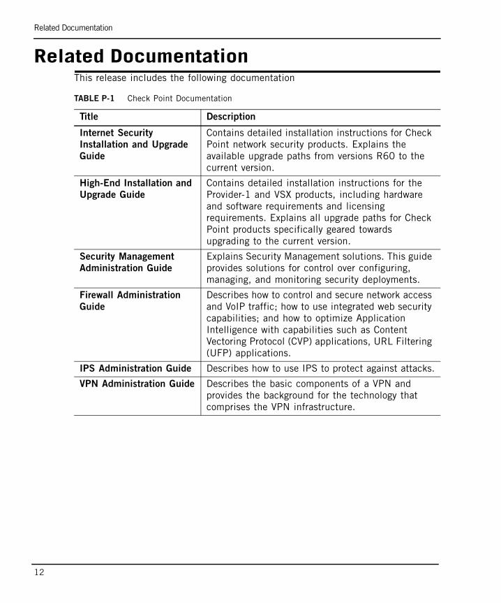
Related DocumentationThis release includes the following documentation
TABLE P-1 Check Point Documentation
Title Description
Internet Security
Installation and Upgrade
Guide
Contains detailed installation instructions for Check Point network security products. Explains the available upgrade paths from versions R60 to the current version.
High-End Installation and
Upgrade Guide
Contains detailed installation instructions for the Provider-1 and VSX products, including hardware and software requirements and licensing requirements. Explains all upgrade paths for Check Point products specifically geared towards upgrading to the current version.
Security Management
Administration Guide
Explains Security Management solutions. This guide provides solutions for control over configuring, managing, and monitoring security deployments.
Firewall Administration
Guide
Describes how to control and secure network access and VoIP traffic; how to use integrated web security capabilities; and how to optimize Application Intelligence with capabilities such as Content Vectoring Protocol (CVP) applications, URL Filtering (UFP) applications.
IPS Administration Guide Describes how to use IPS to protect against attacks.
VPN Administration Guide Describes the basic components of a VPN and provides the background for the technology that comprises the VPN infrastructure.
Related Documentation
Preface 13
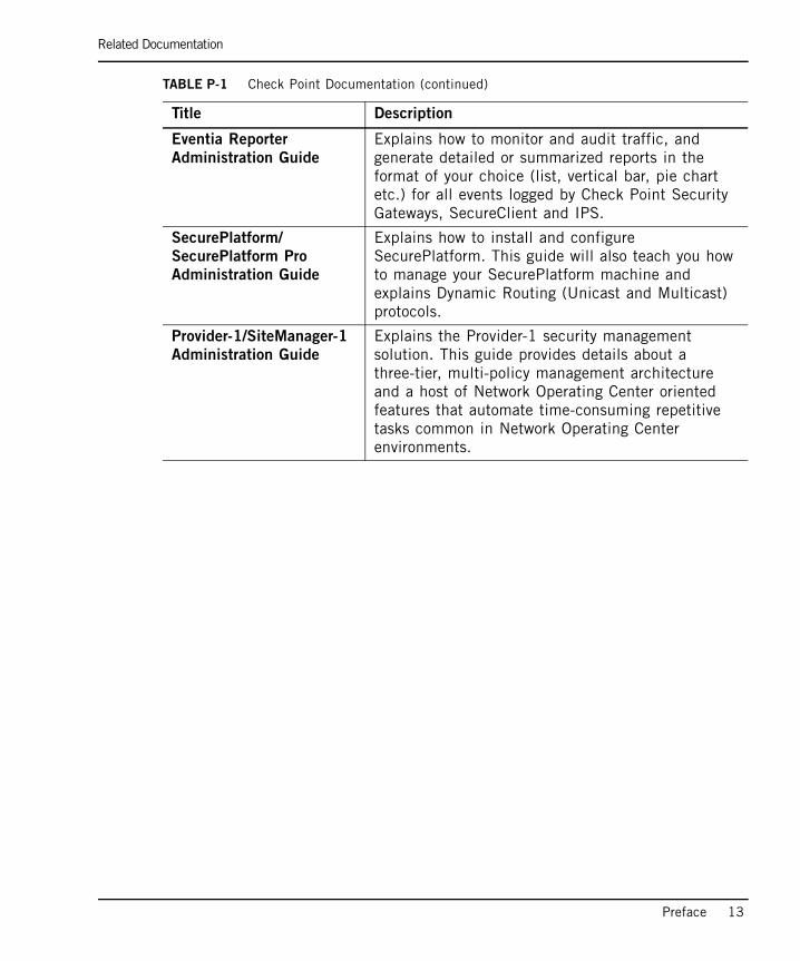
Eventia Reporter
Administration Guide
Explains how to monitor and audit traffic, and generate detailed or summarized reports in the format of your choice (list, vertical bar, pie chart etc.) for all events logged by Check Point Security Gateways, SecureClient and IPS.
SecurePlatform/
SecurePlatform Pro
Administration Guide
Explains how to install and configure SecurePlatform. This guide will also teach you how to manage your SecurePlatform machine and explains Dynamic Routing (Unicast and Multicast) protocols.
Provider-1/SiteManager-1
Administration Guide
Explains the Provider-1 security management solution. This guide provides details about a three-tier, multi-policy management architecture and a host of Network Operating Center oriented features that automate time-consuming repetitive tasks common in Network Operating Center environments.
TABLE P-1 Check Point Documentation (continued)
Title Description
More Information
14
More Information• For additional technical information about Check Point products, consult Check
Point’s SecureKnowledge at http://support.checkpoint.com/.
• See the latest version of this document in the User Center at http://support.checkpoint.com
Feedback
Preface 15
FeedbackCheck Point is engaged in a continuous effort to improve its documentation. Please help us by sending your comments to:

Feedback
16
17
Chapter 1Overview
In This Chapter
What is Quality of Service page 18
Bandwidth Management Technologies page 19
How Does Check Point Deliver QoS page 21
Features and Benefits page 23
Traditional QoS vs. QoS Express page 24
Workflow page 26
What is Quality of Service
18
What is Quality of ServiceQuality of Service is a set of intelligent network protocols and services that are used to efficiently manage the movement of information through a local or wide area networks. QoS services sort and classify flows into different traffic classes, and allocate resources to network traffic flows based on user or application ID, source or destination IP address, time of day, application specific parameters, and other user-specified variables.
Fundamentally, QoS enables you to provide better service to certain flows. This is done by either raising the priority of a flow or limiting the priority of another flow.
Bandwidth Management Technologies
Chapter 1 Overview 19
Bandwidth Management TechnologiesIn This Section
OverviewWhen you connect your network to the Internet, it is most important to make efficient use of the available bandwidth. An effective bandwidth management policy ensures that even at times of network congestion, bandwidth is allocated in accordance with enterprise priorities.
In the past, network bandwidth problems have been addressed either by adding more bandwidth (an expensive and usually short term “solution”) or by router queuing, which is ineffective for complex modern Internet protocols.
Superior QoS Solution RequirementsIn order to provide effective bandwidth management, a bandwidth management tool must track and control the flow of communication passing through, based on information derived from all communication layers and from other applications.
An effective bandwidth management tool must address all of the following issues:
• Fair Prioritization
It is not sufficient to simply prioritize communications, for example, to specify a higher priority for HTTP than for SMTP. The result may well be that all bandwidth resources are allocated to one service and none to another. A bandwidth management tool must be able to divide the available resources so that more important services are allocated more bandwidth, but all services are allocated some bandwidth.
• Minimum Bandwidth
A bandwidth management tool must be able to guarantee a service’s minimum required bandwidth. It must also be able to allocate bandwidth preferentially, for example, to move a company’s video conference to the “head of the line” in preference to all other internet traffic.
Overview page 19
Superior QoS Solution Requirements page 19
Benefits of a Policy-Based Solution page 20
Benefits of a Policy-Based Solution
20
• Classification
A bandwidth management tool must be able to accurately classify communications. However, simply examining a packet in isolation does not provide all the information needed to make an informed decision. State information — derived from past communications and other applications — is also required. A packet’s contents, the communication state and the application state (derived from other applications) must all be considered when making control decisions.
Benefits of a Policy-Based SolutionBased on the principles discussed in the previous section, there are basically three ways to improve the existing best-effort service that enterprise networks and ISPs deliver today:
• Add more bandwidth to the network.
• Prioritize network traffic at the edges of the network.
• Guarantee QoS by enforcing a set of policies that are based on business priorities (policy-based network management) throughout the network.
Of these, only policy-based network management provides a comprehensive QoS solution by:
• Using policies to determine the level of service that applications or customers need.
• Prioritizing network requests.
• Guaranteeing levels of service.
How Does Check Point Deliver QoS
Chapter 1 Overview 21
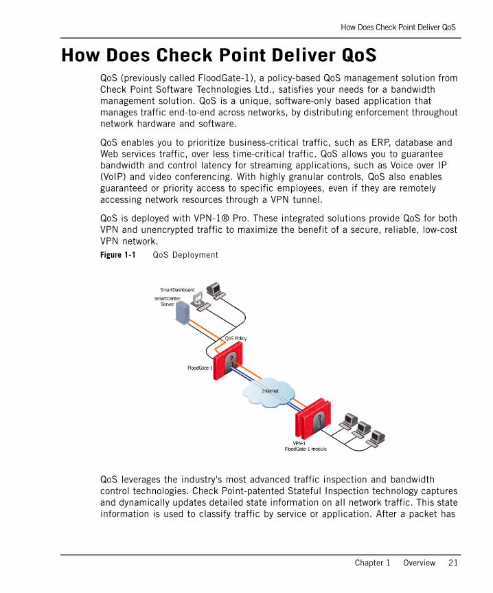
How Does Check Point Deliver QoSQoS (previously called FloodGate-1), a policy-based QoS management solution from Check Point Software Technologies Ltd., satisfies your needs for a bandwidth management solution. QoS is a unique, software-only based application that manages traffic end-to-end across networks, by distributing enforcement throughout network hardware and software.
QoS enables you to prioritize business-critical traffic, such as ERP, database and Web services traffic, over less time-critical traffic. QoS allows you to guarantee bandwidth and control latency for streaming applications, such as Voice over IP (VoIP) and video conferencing. With highly granular controls, QoS also enables guaranteed or priority access to specific employees, even if they are remotely accessing network resources through a VPN tunnel.
QoS is deployed with VPN-1® Pro. These integrated solutions provide QoS for both VPN and unencrypted traffic to maximize the benefit of a secure, reliable, low-cost VPN network.Figure 1-1 QoS Deployment
QoS leverages the industry's most advanced traffic inspection and bandwidth control technologies. Check Point-patented Stateful Inspection technology captures and dynamically updates detailed state information on all network traffic. This state information is used to classify traffic by service or application. After a packet has

How Does Check Point Deliver QoS
22
been classified, QoS applies QoS to the packet by means of an innovative, hierarchical, Weighted Fair Queuing (WFQ) algorithm to precisely control bandwidth allocation.
Features and Benefits
Chapter 1 Overview 23
Features and BenefitsQoS provides the following features and benefits:
• Flexible QoS policies with weights, limits and guarantees: QoS enables you to develop basic policies specific to your requirements. These basic policies can be modified at any time to incorporate any of the Advanced QoS features described in this section.
• Integration with VPN-1 Power or VPN-1 Net: Optimize network performance for VPN and unencrypted traffic: The integration of an organization’s security and bandwidth management policies enables easier policy definition and system configuration.
• Performance analysis through SmartView Tracker: monitor the performance of your system by means of log entries recorded in SmartView Tracker.
• Integrated DiffServ support: add one or more Diffserv Classes of Service to the QoS Policy Rule Base.
• Integrated Low Latency Queuing: define special classes of service for “delay sensitive” applications like voice and video to the QoS Policy Rule Base.
• Integrated Authenticated QoS: provide QoS for end-users in dynamic IP environments, such as remote access and DHCP environments.
• Integrated Citrix MetaFrame support: deliver a QoS solution for the Citrix ICA protocol.
• No need to deploy separate VPN, Firewall and QoS devices: QoS and VPN-1 Power share a similar architecture and many core technology components, therefore users can utilize the same user-defined network objects in both solutions.
• Proactive management of network costs: QoS’s monitoring systems enable you to be proactive in managing your network and thus controlling network costs.
• Support for end-to-end QoS for IP networks: QoS offers complete support for end-to-end QoS for IP networks by distributing enforcement throughout network hardware and software.
Traditional QoS vs. QoS Express
24
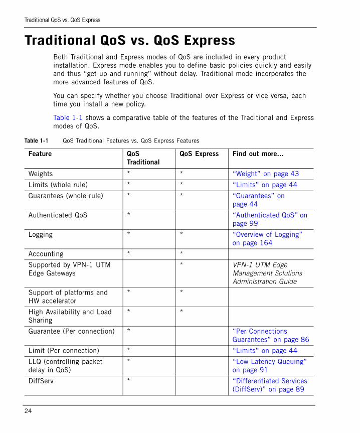
Traditional QoS vs. QoS ExpressBoth Traditional and Express modes of QoS are included in every product installation. Express mode enables you to define basic policies quickly and easily and thus “get up and running” without delay. Traditional mode incorporates the more advanced features of QoS.
You can specify whether you choose Traditional over Express or vice versa, each time you install a new policy.
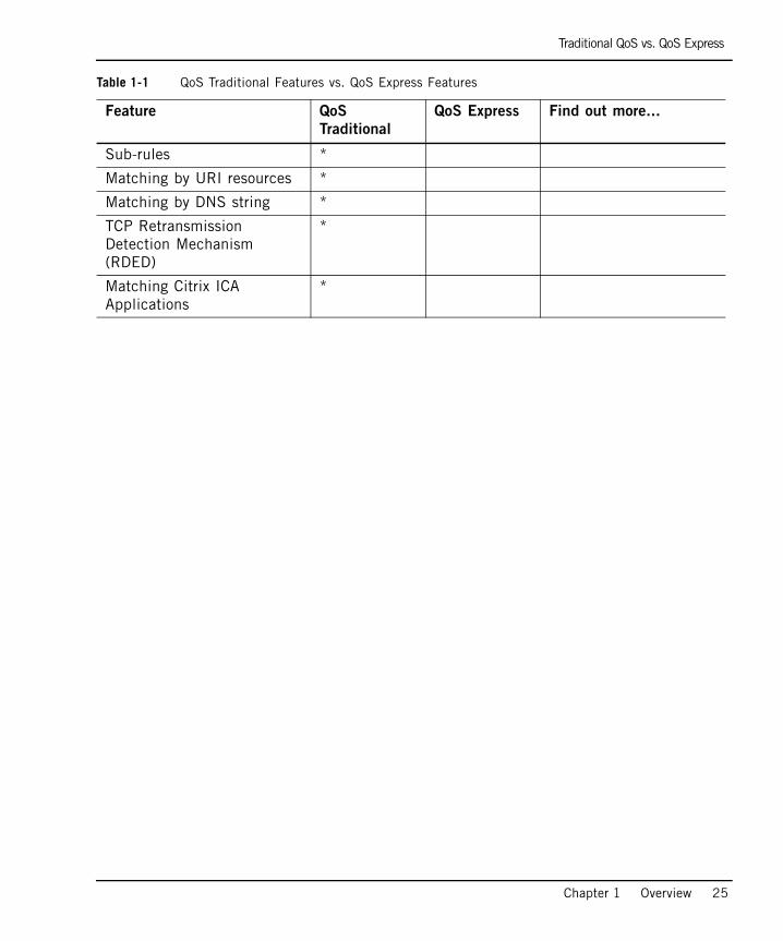
Table 1-1 shows a comparative table of the features of the Traditional and Express modes of QoS.
Table 1-1 QoS Traditional Features vs. QoS Express Features
Feature QoS
Traditional
QoS Express Find out more...
Weights * * “Weight” on page 43
Limits (whole rule) * * “Limits” on page 44
Guarantees (whole rule) * * “Guarantees” on page 44
Authenticated QoS * “Authenticated QoS” on page 99
Logging * * “Overview of Logging” on page 164
Accounting * *
Supported by VPN-1 UTM Edge Gateways
* VPN-1 UTM Edge Management Solutions Administration Guide
Support of platforms and HW accelerator
* *
High Availability and Load Sharing
* *
Guarantee (Per connection) * “Per Connections Guarantees” on page 86
Limit (Per connection) * “Limits” on page 44
LLQ (controlling packet delay in QoS)
* “Low Latency Queuing” on page 91
DiffServ * “Differentiated Services (DiffServ)” on page 89
Traditional QoS vs. QoS Express
Chapter 1 Overview 25
Sub-rules *
Matching by URI resources *
Matching by DNS string *
TCP Retransmission Detection Mechanism (RDED)
*
Matching Citrix ICA Applications
*
Table 1-1 QoS Traditional Features vs. QoS Express Features
Feature QoS
Traditional
QoS Express Find out more...
Workflow
26
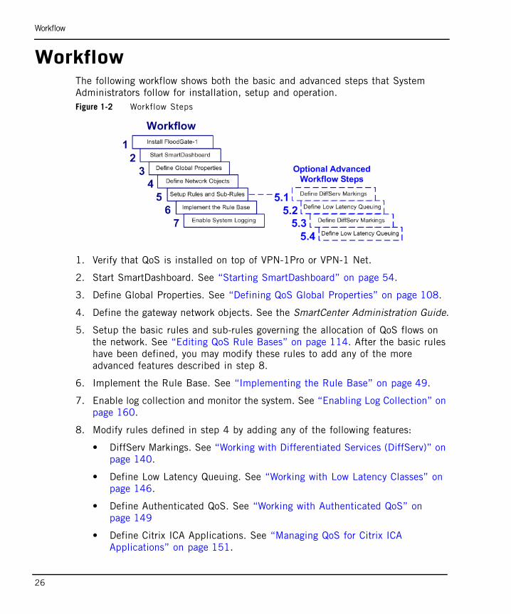
WorkflowThe following workflow shows both the basic and advanced steps that System Administrators follow for installation, setup and operation.Figure 1-2 Workflow Steps
1. Verify that QoS is installed on top of VPN-1Pro or VPN-1 Net.
2. Start SmartDashboard. See “Starting SmartDashboard” on page 54.
3. Define Global Properties. See “Defining QoS Global Properties” on page 108.
4. Define the gateway network objects. See the SmartCenter Administration Guide.
5. Setup the basic rules and sub-rules governing the allocation of QoS flows on the network. See “Editing QoS Rule Bases” on page 114. After the basic rules have been defined, you may modify these rules to add any of the more advanced features described in step 8.
6. Implement the Rule Base. See “Implementing the Rule Base” on page 49.
7. Enable log collection and monitor the system. See “Enabling Log Collection” on page 160.
8. Modify rules defined in step 4 by adding any of the following features:
• DiffServ Markings. See “Working with Differentiated Services (DiffServ)” on page 140.
• Define Low Latency Queuing. See “Working with Low Latency Classes” on page 146.
• Define Authenticated QoS. See “Working with Authenticated QoS” on page 149
• Define Citrix ICA Applications. See “Managing QoS for Citrix ICA Applications” on page 151.
27
Chapter 2Introduction to QoS
In This Chapter
QoS’s Innovative Technology page 28
QoS Architecture page 31
Interaction with VPN-1 page 37
QoS’s Innovative Technology
28
QoS’s Innovative TechnologyQoS is a bandwidth management solution for Internet and Intranet gateways that enables network administrators to set bandwidth policies to solve or alleviate network problems like the bandwidth congestion at network access points. The overall mix of traffic is dynamically controlled by managing bandwidth usage for entire classes of traffic, as well as individual connections. QoS controls both inbound and outbound traffic flows.
Network traffic can be classified by Internet service, source or destination IP address, Internet resource (for example, specific URL designators), user or traffic direction (inbound or outbound). A QoS Policy consists of rules that specify the weights, limits and guarantees that are applied to the different classifications of traffic.
A rule can have multiple sub-rules, enabling an administrator to define highly granular Bandwidth Policies.
QoS provides its real benefits when the network lines become congested. Instead of allowing all traffic to flow arbitrarily, QoS ensures that important traffic takes precedence over less important traffic so that the enterprise can continue to function with minimum disruption, despite network congestion. QoS ensures that an enterprise can make the most efficient use of a congested network.
QoS is completely transparent to both users and applications.
QoS implements four innovative technologies:
• Stateful Inspection: QoS incorporates Check Point’s patented Stateful Inspection technology to derive complete state and context information for all network traffic.
• Intelligent Queuing Engine: This traffic information derived by the Stateful Inspection technology is used by QoS Intelligent Queuing Engine (IQ EngineTM) to accurately classify traffic and place it in the proper transmission queue. The network traffic is then scheduled for transmission based on the QoS Policy. The IQ Engine includes an enhanced, hierarchical Weighted Fair Queuing (WFQ) algorithm to precisely control the allocation of available bandwidth and ensure efficient line utilization.
• WFRED (Weighted Flow Random Early Drop): QoS makes use of WFRED, a mechanism for managing packet buffers that is transparent to the user and requires no pre-configuration.
• RDED (Retransmission Detection Early Drop): QoS makes use of RDED, a mechanism for reducing the number of retransmits and retransmit storms. This Check Point mechanism, drastically reduces retransmit counts, greatly
Technology Overview
Chapter 2 Introduction to QoS 29
improving the efficiency of the enterprise’s existing lines. The increased bandwidth that QoS makes available to important applications comes at the expense of less important (or completely unimportant) applications. As a result purchasing more bandwidth can be significantly delayed.
Technology OverviewQoS contains four innovative technologies, which are discussed in this section.
Stateful InspectionEmploying Stateful Inspection technology, QoS accesses and analyzes data derived from all communication layers. This state and context data is stored and updated dynamically, providing virtual session information for tracking both connection-oriented and connectionless protocols (for example, UDP-based applications). Cumulative data from the communication and application states, network configuration and bandwidth allocation rules are used to classify communications.
Stateful Inspection enables QoS to parse URLs and set priority levels based on file types. For example, QoS can identify HTTP file downloads with *.exe or *.zip extensions and allocates bandwidth accordingly.
Intelligent Queuing EngineQoS uses an enhanced WFQ algorithm to manage bandwidth allocation. A QoS packet scheduler moves packets through a dynamically changing scheduling tree at different rates in accordance with the QoS Policy. High priority packets move through the scheduling tree more quickly than low priority packets.
QoS leverages TCP’s throttling mechanism to automatically adjust bandwidth consumption per individual connections or classes of traffic. Traffic bursts are delayed and smoothed by QoS packet scheduler, holding back the traffic and forcing the application to fit the traffic to the QoS Policy. By intelligently delaying traffic, the IQ Engine effectively controls the bandwidth of all IP traffic.
The preemptive IQ Engine responds immediately to changing traffic conditions and guarantees that high priority traffic always takes precedence over low priority traffic. Accurate bandwidth allocation is achieved even when there are large differences in the weighted priorities (for example 50:1). In addition, since packets are always available for immediate transmission, the IQ Engine provides precise bandwidth control for both inbound and outbound traffic, and ensures 100%
Technology Overview
30
bandwidth utilization during periods of congestion. In addition, in Traditional mode it uses per connection queuing to ensure that every connection receives its fair share of bandwidth.
WFRED (Weighted Flow Random Early Drop)WFRED is a mechanism for managing the packet buffers of QoS. WFRED does not need any preconfiguring. It adjusts automatically and dynamically to the situation and is transparent to the user.
Because the connection of a LAN to the WAN creates a bottleneck, packets that arrive from the LAN are queued before being retransmitted to the WAN. When traffic in the LAN is very intense, queues may become full and packets may be dropped arbitrarily. Dropped packets may reduce the throughput of TCP connections, and the quality of streaming media.
WFRED prevents QoS buffers from being filled by sensing when traffic becomes intense and dropping packets selectively. The mechanism considers every connection separately, and drops packets according to the connection characteristics and overall state of the buffer.
Unlike mechanisms such as RED/WRED, which rely on the TOS byte in the IP header (which is seldom used), WFRED queries QoS as to the priority of the connection, and then uses this information. WFRED protects “fragile” connections from more “aggressive” ones, whether they are TCP or UDP, and always leaves some buffer space for new connections to open.
RDED (Retransmit Detect Early Drop)TCP exhibits extreme inefficiency under certain bandwidth and latency conditions. For example, the bottleneck that results from the connection of a LAN to the WAN causes TCP to retransmit packets. RDED prevents inefficiencies by detecting retransmits in TCP streams and preventing the transmission of redundant packets when multiple copies of a packet are concurrently queued on the same flow. The result is a dramatic reduction of retransmit counts and positive feedback retransmit loops. Implementing RDED requires the combination of intelligent queuing and full reconstruction of TCP streams, capabilities that exist together only in QoS.
QoS Architecture
Chapter 2 Introduction to QoS 31
QoS ArchitectureIn This Section
Basic ArchitectureThe architecture and flow control of QoS is similar to Firewall. QoS has three components:
• SmartConsole
• SmartCenter Server
• Gateway
The components can be installed on one machine or in a distributed configuration on a number of machines.
Bandwidth policy is created using SmartDashboard. The policy is downloaded to the SmartCenter Server where it is verified and downloaded to the QoS Gateways using CPD (Check Point Daemon), which is run on the gateway and the SmartCenter Server. The QoS gateway uses the Firewall chaining mechanism (see below) to receive, process and send packets. QoS uses a proprietary classifying and rule-matching infrastructure to examine a packet. Logging information is provided using Firewall kernel API.
QoS GatewayThe major role of the QoS gateway is to implement a QoS policy at network access points and control the flow of inbound and outbound traffic. It includes two main parts:
• QoS kernel driver
• QoS daemon
Basic Architecture page 31
QoS Architecture page 31
QoS Configuration page 33
Basic Architecture
32
QoS Kernel Driver
The kernel driver is the heart of QoS operations. It is in the kernel driver that IP packets are examined, queued, scheduled and released, enabling QoS traffic control abilities. Utilizing Firewall kernel services, QoS functionality is a part of the cookie chain, a Check Point infrastructure mechanism that allows gateways to operate on each packet as it travels from the link layer (the machine network card driver) to the network layer (its IP stack), or vice versa.
QoS Daemon (fgd50)
The QoS daemon is a user mode process used to perform tasks that are difficult for the kernel. It currently performs 2 tasks for the kernel (using Traps):
• Resolving DNS for the kernel (used for Rule Base matching).
• Resolving Authenticated Data for an IP (using UserAuthority - again for Rule Base matching).
• In CPLS configuration, the daemon updates the kernel of any change in the cluster status. For example, if a cluster member goes down the daemon recalculates the relative loads of the gateways and updates the kernel.
QoS SmartCenter ServerThe QoS SmartCenter Server is an add-on to the SmartCenter Server (fwm). The SmartCenter Server, which is controlled by SmartConsole clients, provides general services to QoS and is capable of issuing QoS functions by running QoS command line utilities. It is used to configure the bandwidth policy and control QoS gateways. A single SmartCenter Server can control multiple QoS gateways running either on the same machine as the SmartCenter Server or on remote machines. The SmartCenter Server also manages the Log Repository and acts as a log server for the SmartView Tracker. The SmartCenter server is a user mode process that communicates with the gateway using CPD.
QoS SmartConsoleThe main SmartConsole application is SmartDashboard. By creating "bandwidth rules" the SmartDashboard allows system administrators to define a network QoS policy to be enforced by QoS.
Other SmartConsole clients are the SmartView Tracker - a log entries browser; and SmartView Status which displays status information about active QoS gateways and their policies.
QoS Configuration
Chapter 2 Introduction to QoS 33
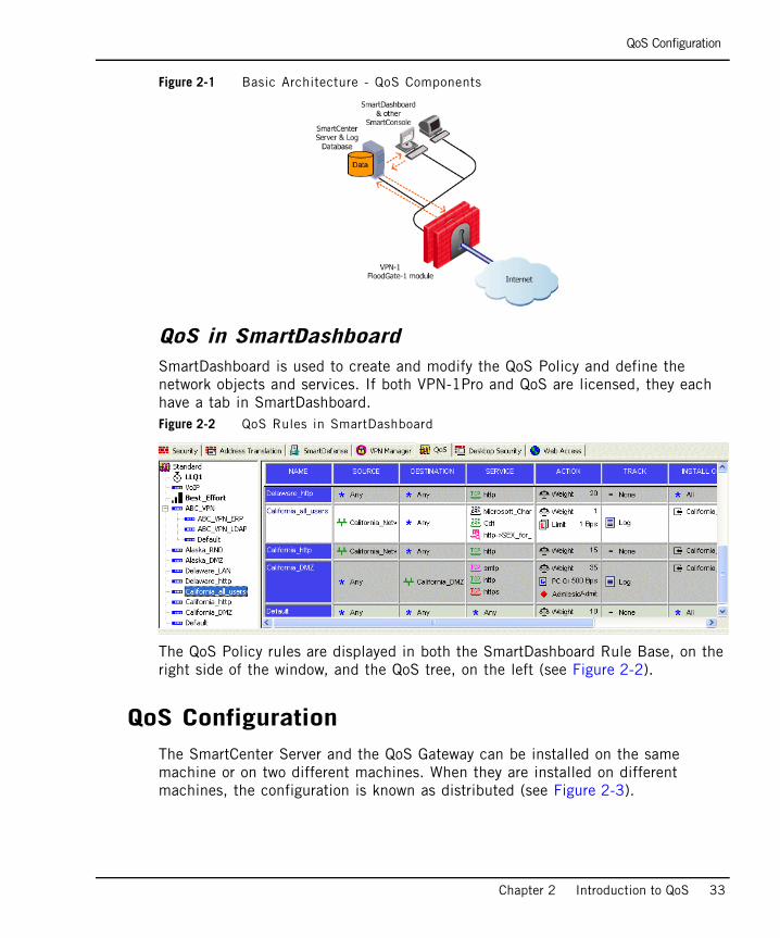
Figure 2-1 Basic Architecture - QoS Components
QoS in SmartDashboardSmartDashboard is used to create and modify the QoS Policy and define the network objects and services. If both VPN-1Pro and QoS are licensed, they each have a tab in SmartDashboard.Figure 2-2 QoS Rules in SmartDashboard
The QoS Policy rules are displayed in both the SmartDashboard Rule Base, on the right side of the window, and the QoS tree, on the left (see Figure 2-2).
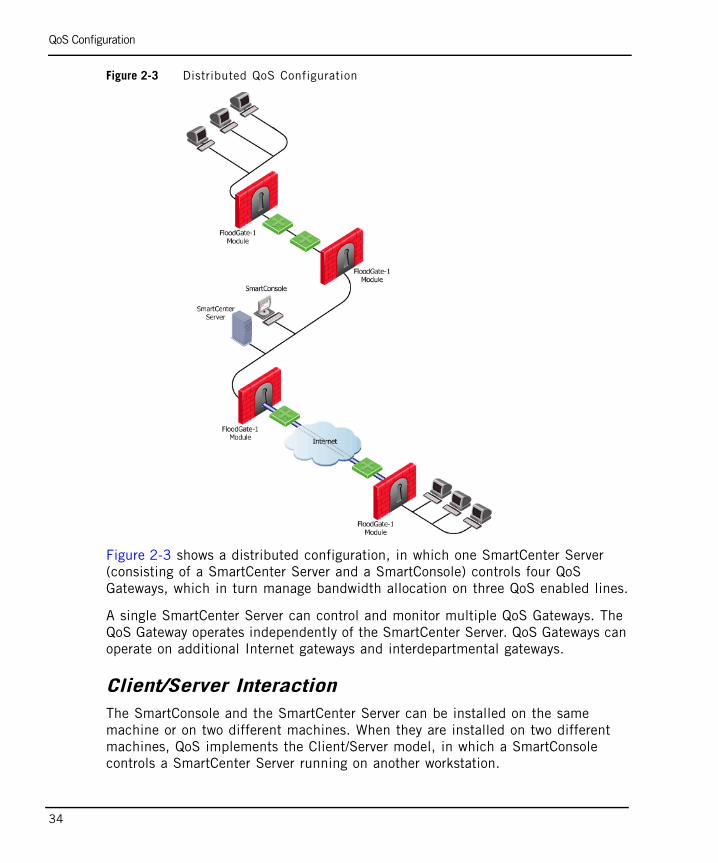
QoS ConfigurationThe SmartCenter Server and the QoS Gateway can be installed on the same machine or on two different machines. When they are installed on different machines, the configuration is known as distributed (see Figure 2-3).
QoS Configuration
34
Figure 2-3 Distributed QoS Configuration
Figure 2-3 shows a distributed configuration, in which one SmartCenter Server (consisting of a SmartCenter Server and a SmartConsole) controls four QoS Gateways, which in turn manage bandwidth allocation on three QoS enabled lines.
A single SmartCenter Server can control and monitor multiple QoS Gateways. The QoS Gateway operates independently of the SmartCenter Server. QoS Gateways can operate on additional Internet gateways and interdepartmental gateways.
Client/Server InteractionThe SmartConsole and the SmartCenter Server can be installed on the same machine or on two different machines. When they are installed on two different machines, QoS implements the Client/Server model, in which a SmartConsole controls a SmartCenter Server running on another workstation.
QoS Configuration
Chapter 2 Introduction to QoS 35
Figure 2-4 QoS Client/Server Configuration
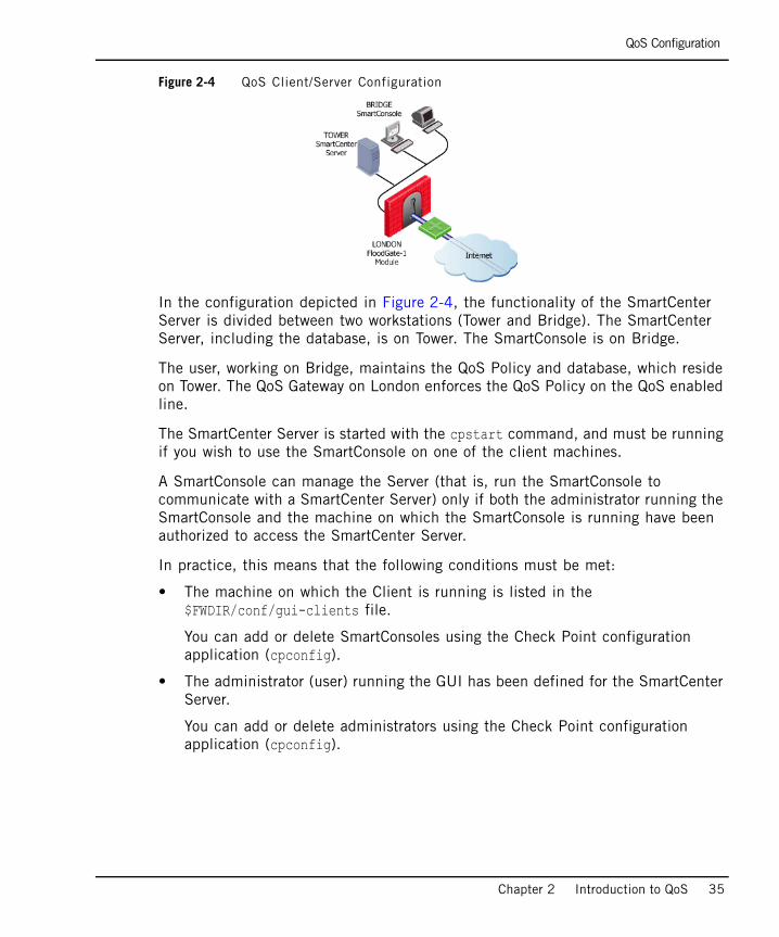
In the configuration depicted in Figure 2-4, the functionality of the SmartCenter Server is divided between two workstations (Tower and Bridge). The SmartCenter Server, including the database, is on Tower. The SmartConsole is on Bridge.
The user, working on Bridge, maintains the QoS Policy and database, which reside on Tower. The QoS Gateway on London enforces the QoS Policy on the QoS enabled line.
The SmartCenter Server is started with the cpstart command, and must be running if you wish to use the SmartConsole on one of the client machines.
A SmartConsole can manage the Server (that is, run the SmartConsole to communicate with a SmartCenter Server) only if both the administrator running the SmartConsole and the machine on which the SmartConsole is running have been authorized to access the SmartCenter Server.
In practice, this means that the following conditions must be met:
• The machine on which the Client is running is listed in the$FWDIR/conf/gui-clients file.
You can add or delete SmartConsoles using the Check Point configuration application (cpconfig).
• The administrator (user) running the GUI has been defined for the SmartCenter Server.
You can add or delete administrators using the Check Point configuration application (cpconfig).
Concurrent Sessions
36
Concurrent SessionsIn order to prevent more than one administrator from modifying a QoS Policy at the same time, QoS implements a locking mechanism. All but one open policy is ‘Read Only’.
Interaction with VPN-1
Chapter 2 Introduction to QoS 37
Interaction with VPN-1In This Section
InteroperabilityQoS must be installed together with VPN-1 Power or VPN-1 Net on the same system. QoS is installed on top of a VPN-1 Power or VPN-1 Net. Because QoS and VPN-1 Power or VPN-1 Net share a similar architecture and many core technology components, users can utilize the same user-defined network objects in both solutions. This integration of an organization’s security and bandwidth management policies enables easier policy definition and system configuration. Both products can also share state table information which provides efficient traffic inspection and enhanced product performance. QoS, with its tight integration with VPN-1, provides the unique ability to enable users that deploy the solutions in tandem to define bandwidth allocation rules for encrypted and network-address-translated traffic.
SmartCenter ServerIf QoS is installed on a machine on which VPN-1 Power or VPN-1 Net is also installed, QoS uses the VPN-1 Power or VPN-1 Net SmartCenter Server and shares the same objects database (network objects, services and resources) with VPN-1 Power or VPN-1 Net. Some types of objects have properties which are product specific. For example, a VPN-1 Power has encryption properties which are not relevant to QoS, and a QoS network interface has speed properties which are not relevant to VPN-1 Power.
Interoperability page 37

Interoperability
38
39
Chapter 3Basic Policy Management
In This Chapter
Overview page 40
Rule Base Management page 41
Implementing the Rule Base page 49
Overview
40
OverviewThis chapter describes the basic QoS policy management that is required to enable you to define and implement a working QoS Rule Base. More advanced QoS policy management features are discussed in Chapter 5, “Advanced QoS Policy Management””.
Rule Base Management
Chapter 3 Basic Policy Management 41
Rule Base ManagementIn This Section
OverviewQoS policy is implemented by defining an ordered set of rules in the Rule Base. The Rule Base specifies what actions are to be taken with the data packets. It specifies the source and destination of the communication, what services can be used, and at what times, whether to log the connection and the logging level.
The Rule Base comprises the rules you create and a default rule (see Default Rule page 45). The default rule is automatically created with the Rule Base. It can be modified but cannot be deleted. The fundamental concept of the Rule Base is that unless other rules apply, the default rule is applied to all data packets. The default rule is therefore always the last rule in the Rule Base.
A very important aspect of Rule Base management is reviewing SmartView Tracker traffic logs and particular attention should be paid to this aspect of management.
QoS works by inspecting packets in a sequential manner. When QoS receives a packet belonging to a connection, it compares it against the first rule in the Rule Base, then the second, then the third, and so on. When it finds a rule that matches, it stops checking and applies that rule. If the matching rule has sub-rules the packets are then compared against the first sub-rule, then the second and so on until it finds a match. If the packet goes through all the rules or sub-rules without finding a match, then the default rule or default sub-rule is applied. It is important to understand that the first rule that matches is applied to the packet, not the rule that best matches.
Overview page 41
Connection Classification page 42
Services and Resources page 43
Time Objects page 43
Bandwidth Allocation and Rules page 43
Default Rule page 45
QoS Action Properties page 45
Example of a Rule Matching VPN Traffic page 46
Bandwidth Allocation and Sub-Rules page 47
Connection Classification
42
After you have defined your network objects, services and resources, you can use them in building a Rule Base. For installation instructions and instructions on building a Rule Base, see “Editing QoS Rule Bases” on page 114.
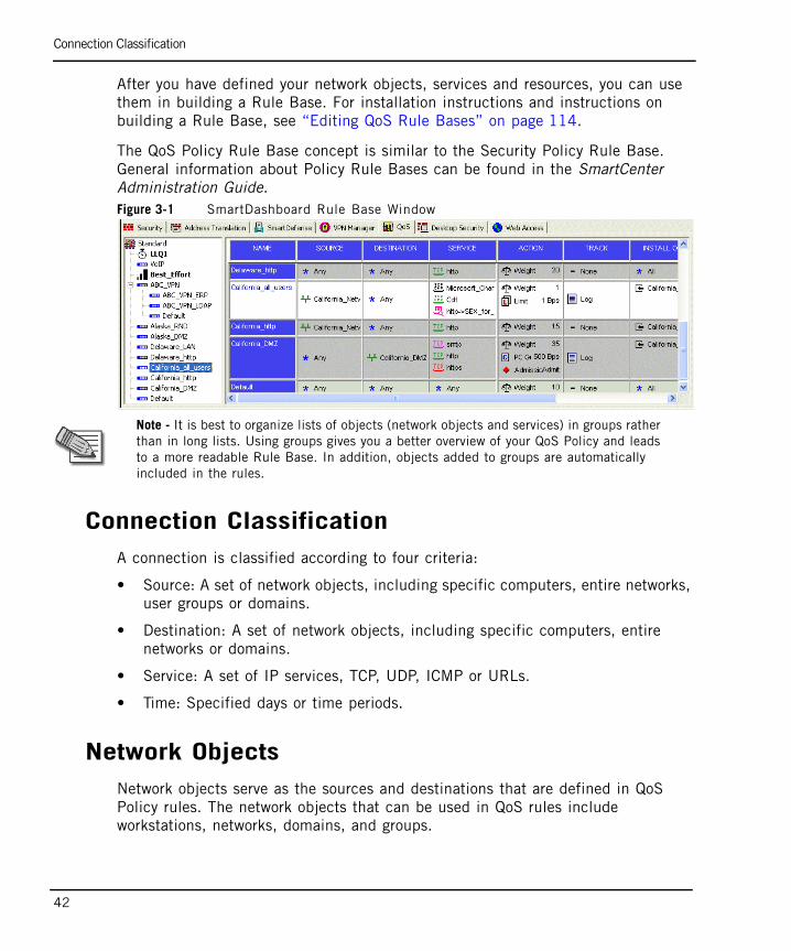
The QoS Policy Rule Base concept is similar to the Security Policy Rule Base. General information about Policy Rule Bases can be found in the SmartCenter Administration Guide.Figure 3-1 SmartDashboard Rule Base Window
Connection ClassificationA connection is classified according to four criteria:
• Source: A set of network objects, including specific computers, entire networks, user groups or domains.
• Destination: A set of network objects, including specific computers, entire networks or domains.
• Service: A set of IP services, TCP, UDP, ICMP or URLs.
• Time: Specified days or time periods.
Network ObjectsNetwork objects serve as the sources and destinations that are defined in QoS Policy rules. The network objects that can be used in QoS rules include workstations, networks, domains, and groups.
Note - It is best to organize lists of objects (network objects and services) in groups rather than in long lists. Using groups gives you a better overview of your QoS Policy and leads to a more readable Rule Base. In addition, objects added to groups are automatically included in the rules.
Services and Resources
Chapter 3 Basic Policy Management 43
Information about network objects can be found in the SmartCenter Administration Guide.
User GroupsQoS allows you to define User Groups that are comprised of predefined users. For example, all the users in the marketing department can be grouped together in a User Group called Marketing. when defining a Source in a rule you can then use this group as a possible Source, instead of adding individual users to the Source of the rule.
Services and ResourcesQoS allows you to define QoS rules, not only based on the source and destination of each communication, but also according to the service requested. The services that can be used in QoS rules include TCP, Compound TCP, UDP, ICMP and Citrix TCP services, IP services
Resources can also be used in a QoS Rule Base. They must be of type URI for QoS.
Time ObjectsQoS allows you to define Time objects that are used is defining the time that a rule is operational. Time objects can be defined for specific times and/or for specific days. The days can further be divided into days of the month or specific days of the week.
Bandwidth Allocation and RulesA rule can specify three factors to be applied to bandwidth allocation for classified connections:
WeightWeight is the relative portion of the available bandwidth that is allocated to a rule.
To calculate what portion of the bandwidth the connections matched to a rule receive, use the following formula:
this rule’s portion = this rule’s weight / total weight of all rules with open connections
Bandwidth Allocation and Rules
44
For example, if this rule’s weight is 12 and the total weight of all the rules under which connections are currently open is 120, then all the connections open under this rule are allocated 12/120 (or 10%) of the available bandwidth.
In practice, a rule may get more than the bandwidth allocated by this formula, if other rules are not using their maximum allocated bandwidth.
Unless a per connection limit or guarantee is defined for a rule, all connections under a rule receive equal weight.
Allocating bandwidth according to weights ensures full utilization of the line even if a specific class is not using all of its bandwidth. In such a case, the left over bandwidth is divided among the remaining classes in accordance with their relative weights. Units are configurable, see “Defining QoS Global Properties” on page 108.
GuaranteesA guarantee allocates a minimum bandwidth to the connections matched with a rule.
Guarantees can be defined for:
• the sum of all connections within a rule
A total rule guarantee reserves a minimum bandwidth for all the connections under a rule combined. The actual bandwidth allocated to each connection depends on the number of open connections that match the rule. The total bandwidth allocated to the rule can be no less than the guarantee, but the more connections that are open, the less bandwidth each one receives.
• individual connections within a rule
A per connection guarantee means that each connection that matches the particular rule is guaranteed a minimum bandwidth.
Although weights do in fact guarantee the bandwidth share for specific connections, only a guarantee allows you to specify an absolute bandwidth value.
LimitsA limit specifies the maximum bandwidth that is assigned to all the connections together. A limit defines a point beyond which connections under a rule are not allocated bandwidth, even if there is unused bandwidth available.
Limits can also be defined for the sum of all connections within a rule or for individual connections within a rule.
Default Rule
Chapter 3 Basic Policy Management 45
For more information on weights, guarantees and limits, see “Action Type” on page 45.
Default RuleA default rule is automatically added to each QoS Policy Rule Base, and assigned the weight specified in the QoS page of the Global Properties window. You can modify the weight, but you cannot delete the default rule (see “Weight” on page 43).
The default rule applies to all connections not matched by the other rules or sub-rules in the Rule Base.
In addition, a default rule is automatically added to each group of sub-rules, and applies to connections not classified by the other sub-rules in the group (see “To Verify and View the QoS Policy” on page 49).
QoS Action PropertiesIn the QoS Action Properties window you can define bandwidth allocation properties, limits and guarantees for a rule.
Action TypeBy this stage, you should already have decided whether your policy is Traditional mode or Express mode, see “Traditional QoS vs. QoS Express” on page 24.
You can select one of the following Action Types:
• Simple
• Advanced
Note - Bandwidth allocation is not fixed. As connections are opened and closed, QoS continuously changes the bandwidth allocation to accommodate competing connections, in accordance with the QoS Policy.
Example of a Rule Matching VPN Traffic
46
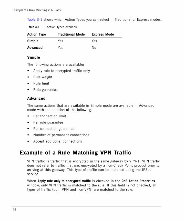
Table 3-1 shows which Action Types you can select in Traditional or Express modes.
Simple
The following actions are available:
• Apply rule to encrypted traffic only
• Rule weight
• Rule limit
• Rule guarantee
Advanced
The same actions that are available in Simple mode are available in Advanced mode with the addition of the following:
• Per connection limit
• Per rule guarantee
• Per connection guarantee
• Number of permanent connections
• Accept additional connections
Example of a Rule Matching VPN TrafficVPN traffic is traffic that is encrypted in the same gateway by VPN-1. VPN traffic does not refer to traffic that was encrypted by a non-Check Point product prior to arriving at this gateway. This type of traffic can be matched using the IPSec service.
When Apply rule only to encrypted traffic is checked in the QoS Action Properties window, only VPN traffic is matched to the rule. If this field is not checked, all types of traffic (both VPN and non-VPN) are matched to the rule.
Table 3-1 Action Types Available
Action Type Traditional Mode Express Mode
Simple Yes Yes
Advanced Yes No
Bandwidth Allocation and Sub-Rules
Chapter 3 Basic Policy Management 47
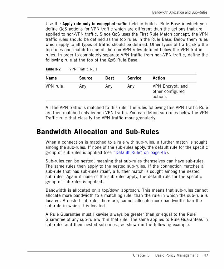
Use the Apply rule only to encrypted traffic field to build a Rule Base in which you define QoS actions for VPN traffic which are different than the actions that are applied to non-VPN traffic. Since QoS uses the First Rule Match concept, the VPN traffic rules should be defined as the top rules in the Rule Base. Below them rules which apply to all types of traffic should be defined. Other types of traffic skip the top rules and match to one of the non-VPN rules defined below the VPN traffic rules. In order to completely separate VPN traffic from non-VPN traffic, define the following rule at the top of the QoS Rule Base:
All the VPN traffic is matched to this rule. The rules following this VPN Traffic Rule are then matched only by non-VPN traffic. You can define sub-rules below the VPN Traffic rule that classify the VPN traffic more granularly.
Bandwidth Allocation and Sub-RulesWhen a connection is matched to a rule with sub-rules, a further match is sought among the sub-rules. If none of the sub-rules apply, the default rule for the specific group of sub-rules is applied (see “Default Rule” on page 45).
Sub-rules can be nested, meaning that sub-rules themselves can have sub-rules. The same rules then apply to the nested sub-rules. If the connection matches a sub-rule that has sub-rules itself, a further match is sought among the nested sub-rules. Again if none of the sub-rules apply, the default rule for the specific group of sub-rules is applied.
Bandwidth is allocated on a top/down approach. This means that sub-rules cannot allocate more bandwidth to a matching rule, than the rule in which the sub-rule is located. A nested sub-rule, therefore, cannot allocate more bandwidth than the sub-rule in which it is located.
A Rule Guarantee must likewise always be greater than or equal to the Rule Guarantee of any sub-rule within that rule. The same applies to Rule Guarantees in sub-rules and their nested sub-rules., as shown in the following example.
Table 3-2 VPN Traffic Rule
Name Source Dest Service Action
VPN rule Any Any Any VPN Encrypt, and other configured actions
Bandwidth Allocation and Sub-Rules
48
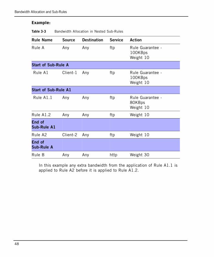
Example:
In this example any extra bandwidth from the application of Rule A1.1 is applied to Rule A2 before it is applied to Rule A1.2.
Table 3-3 Bandwidth Allocation in Nested Sub-Rules
Rule Name Source Destination Service Action
Rule A Any Any ftp Rule Guarantee - 100KBpsWeight 10
Start of Sub-Rule A
Rule A1 Client-1 Any ftp Rule Guarantee - 100KBpsWeight 10
Start of Sub-Rule A1
Rule A1.1 Any Any ftp Rule Guarantee - 80KBpsWeight 10
Rule A1.2 Any Any ftp Weight 10
End of
Sub-Rule A1
Rule A2 Client-2 Any ftp Weight 10
End of
Sub-Rule A
Rule B Any Any http Weight 30
Implementing the Rule Base
Chapter 3 Basic Policy Management 49
Implementing the Rule BaseWhen you have defined the desired rules, you should perform a heuristic check on the Rule Base to check that the rules are consistent. If a Rule Base fails the verification, an appropriate message is displayed.
You must save the Policy Package before verifying. Otherwise, changes made since the last save will not be checked.
After verifying the correctness of the Rule Base, it must be installed on the QoS Gateways that will enforce it. When you install a QoS Policy, the policy is downloaded to these QoS Gateways. There must be a QoS gateway running on the object which receives the QoS Policy.
In This Section
To Verify and View the QoS Policy1. Select Policy>Verify to perform a heuristic check on the Rule Base to check
that the rules are consistent.
2. Select Policy>View to view the generated rules as ASCII text.
To Install and Enforce the PolicyPerform the following steps in order to install and enforce the QoS policy:
1. Once the rule base is complete, select Install from the Policy menu. The Install Policy window is displayed. Specify the QoS gateways on which you would like to install your new QoS policy. By default, all QoS gateways are already selected. (In order for an object to be a QoS gateway, it needs to have QoS checked under Check Point Products in the Object Properties window).
Note - The QoS gateway machine and the SmartCenter gateway machine must be properly configured before a QoS Policy can be installed.
To Verify and View the QoS Policy page 49
To Install and Enforce the Policy page 49
To Uninstall the QoS Policy page 50
To Monitor the QoS Policy page 50
To Uninstall the QoS Policy
50
The objects in the list are those that have QoS Installed checked in their definition (see “Specifying Interface QoS Properties” on page 110).
You may deselect and reselect specific items, if you wish. The QoS Policy is not installed on unselected items.
2. Click OK to install the QoS Policy on all selected hosts. The installation progress window is displayed.
To Uninstall the QoS PolicyYou can uninstall QoS Policy from any or all of the QoS gateways in which it is installed.
1. Choose Uninstall from the Policy menu to remove the QoS Policy from the selected QoS gateway. The Install Policy window is displayed.
2. Deselect those QoS gateways from which you would like to uninstall the QoS policy.
3. Click OK.
To Monitor the QoS PolicySmartView Monitor allows you to monitor traffic through a QoS interface. For more information, see SmartView Monitor Administration Guide.
51
Chapter 4QoS Tutorial
In This Chapter
Introduction page 52
Building and Installing a QoS Policy page 53
Conclusion page 79
Introduction
52
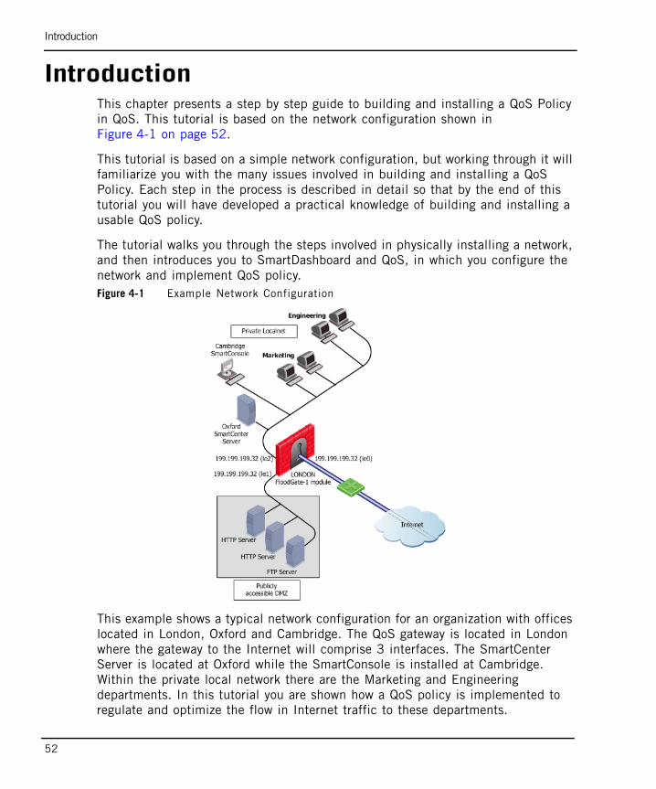
IntroductionThis chapter presents a step by step guide to building and installing a QoS Policy in QoS. This tutorial is based on the network configuration shown in Figure 4-1 on page 52.
This tutorial is based on a simple network configuration, but working through it will familiarize you with the many issues involved in building and installing a QoS Policy. Each step in the process is described in detail so that by the end of this tutorial you will have developed a practical knowledge of building and installing a usable QoS policy.
The tutorial walks you through the steps involved in physically installing a network, and then introduces you to SmartDashboard and QoS, in which you configure the network and implement QoS policy.Figure 4-1 Example Network Configuration
This example shows a typical network configuration for an organization with offices located in London, Oxford and Cambridge. The QoS gateway is located in London where the gateway to the Internet will comprise 3 interfaces. The SmartCenter Server is located at Oxford while the SmartConsole is installed at Cambridge. Within the private local network there are the Marketing and Engineering departments. In this tutorial you are shown how a QoS policy is implemented to regulate and optimize the flow in Internet traffic to these departments.
Building and Installing a QoS Policy
Chapter 4 QoS Tutorial 53
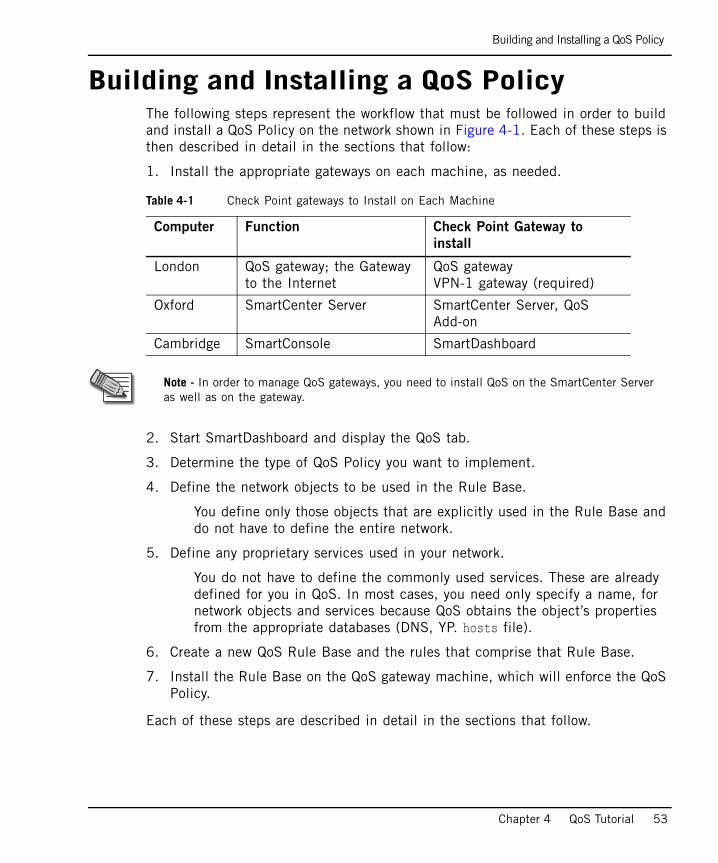
Building and Installing a QoS PolicyThe following steps represent the workflow that must be followed in order to build and install a QoS Policy on the network shown in Figure 4-1. Each of these steps is then described in detail in the sections that follow:
1. Install the appropriate gateways on each machine, as needed.
2. Start SmartDashboard and display the QoS tab.
3. Determine the type of QoS Policy you want to implement.
4. Define the network objects to be used in the Rule Base.
You define only those objects that are explicitly used in the Rule Base and do not have to define the entire network.
5. Define any proprietary services used in your network.
You do not have to define the commonly used services. These are already defined for you in QoS. In most cases, you need only specify a name, for network objects and services because QoS obtains the object’s properties from the appropriate databases (DNS, YP. hosts file).
6. Create a new QoS Rule Base and the rules that comprise that Rule Base.
7. Install the Rule Base on the QoS gateway machine, which will enforce the QoS Policy.
Each of these steps are described in detail in the sections that follow.
Table 4-1 Check Point gateways to Install on Each Machine
Computer Function Check Point Gateway to
install
London QoS gateway; the Gateway to the Internet
QoS gatewayVPN-1 gateway (required)
Oxford SmartCenter Server SmartCenter Server, QoS Add-on
Cambridge SmartConsole SmartDashboard
Note - In order to manage QoS gateways, you need to install QoS on the SmartCenter Server as well as on the gateway.
Installing Check Point Gateways
54
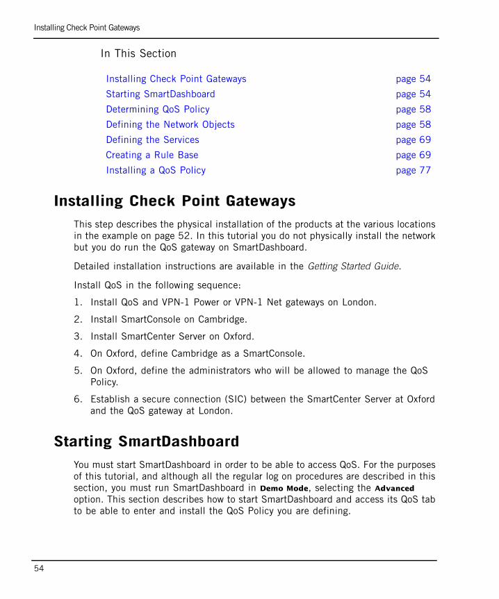
In This Section
Installing Check Point GatewaysThis step describes the physical installation of the products at the various locations in the example on page 52. In this tutorial you do not physically install the network but you do run the QoS gateway on SmartDashboard.
Detailed installation instructions are available in the Getting Started Guide.
Install QoS in the following sequence:
1. Install QoS and VPN-1 Power or VPN-1 Net gateways on London.
2. Install SmartConsole on Cambridge.
3. Install SmartCenter Server on Oxford.
4. On Oxford, define Cambridge as a SmartConsole.
5. On Oxford, define the administrators who will be allowed to manage the QoS Policy.
6. Establish a secure connection (SIC) between the SmartCenter Server at Oxford and the QoS gateway at London.
Starting SmartDashboardYou must start SmartDashboard in order to be able to access QoS. For the purposes of this tutorial, and although all the regular log on procedures are described in this section, you must run SmartDashboard in Demo Mode, selecting the Advanced option. This section describes how to start SmartDashboard and access its QoS tab to be able to enter and install the QoS Policy you are defining.
Installing Check Point Gateways page 54
Starting SmartDashboard page 54
Determining QoS Policy page 58
Defining the Network Objects page 58
Defining the Services page 69
Creating a Rule Base page 69
Installing a QoS Policy page 77
Starting SmartDashboard
Chapter 4 QoS Tutorial 55
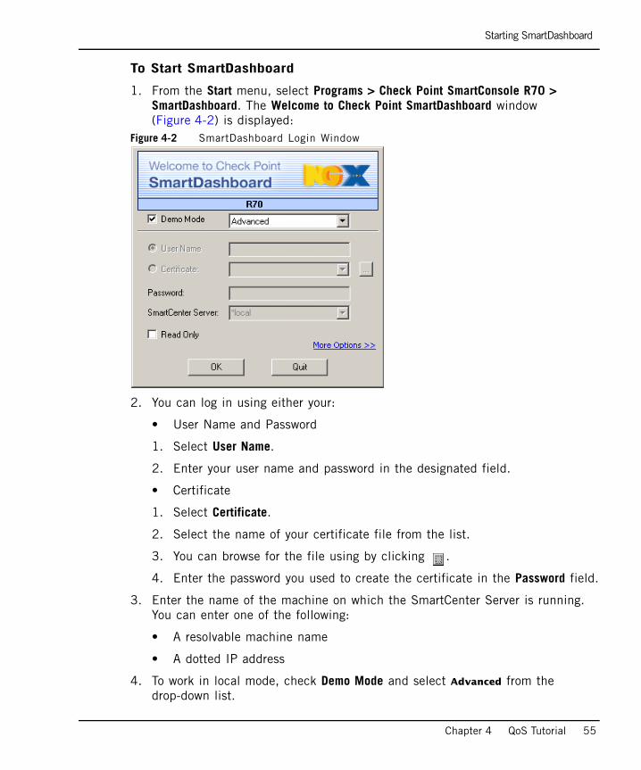
To Start SmartDashboard
1. From the Start menu, select Programs > Check Point SmartConsole R70 > SmartDashboard. The Welcome to Check Point SmartDashboard window (Figure 4-2) is displayed:
Figure 4-2 SmartDashboard Login Window
2. You can log in using either your:
• User Name and Password
1. Select User Name.
2. Enter your user name and password in the designated field.
• Certificate
1. Select Certificate.
2. Select the name of your certificate file from the list.
3. You can browse for the file using by clicking .
4. Enter the password you used to create the certificate in the Password field.
3. Enter the name of the machine on which the SmartCenter Server is running. You can enter one of the following:
• A resolvable machine name
• A dotted IP address
4. To work in local mode, check Demo Mode and select Advanced from the drop-down list.
Starting SmartDashboard
56
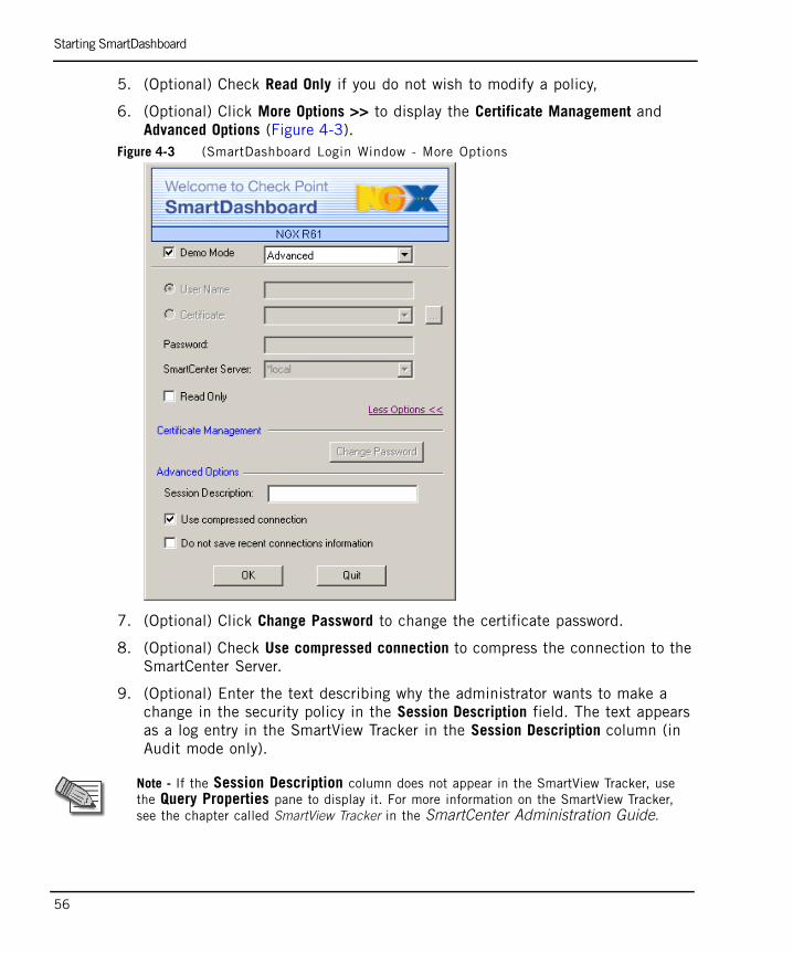
5. (Optional) Check Read Only if you do not wish to modify a policy,
6. (Optional) Click More Options >> to display the Certificate Management and Advanced Options (Figure 4-3).
Figure 4-3 (SmartDashboard Login Window - More Options
7. (Optional) Click Change Password to change the certificate password.
8. (Optional) Check Use compressed connection to compress the connection to the SmartCenter Server.
9. (Optional) Enter the text describing why the administrator wants to make a change in the security policy in the Session Description field. The text appears as a log entry in the SmartView Tracker in the Session Description column (in Audit mode only).
Note - If the Session Description column does not appear in the SmartView Tracker, use the Query Properties pane to display it. For more information on the SmartView Tracker, see the chapter called SmartView Tracker in the SmartCenter Administration Guide.
Starting SmartDashboard
Chapter 4 QoS Tutorial 57
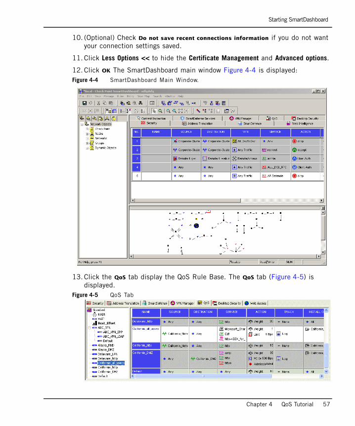
10. (Optional) Check Do not save recent connections information if you do not want your connection settings saved.
11. Click Less Options << to hide the Certificate Management and Advanced options.
12. Click OK The SmartDashboard main window Figure 4-4 is displayed:Figure 4-4 SmartDashboard Main Window.
13. Click the QoS tab display the QoS Rule Base. The QoS tab (Figure 4-5) is displayed.
Figure 4-5 QoS Tab
Starting SmartDashboard
58
Determining QoS Policy
To implement an effective QoS Policy, you must first determine how you currently use your network, and then identify and prioritize the types of traffic and the users who are going to use the network.
For example, a typical QoS Policy would be:
• HTTP traffic should be allocated more bandwidth than RealAudio.
• Marketing should be allocated more bandwidth than Engineering.
You will create the rules to implement this policy in “Creating a Rule Base” on page 69.
Defining the Network Objects
You must now define the Network Objects including London, the gateway on which the QoS gateway is running, and its interfaces, as well as the sub-networks for the Marketing and Engineering departments.
This step describes, as an example, how the gateway London will be defined.
Starting SmartDashboard
Chapter 4 QoS Tutorial 59
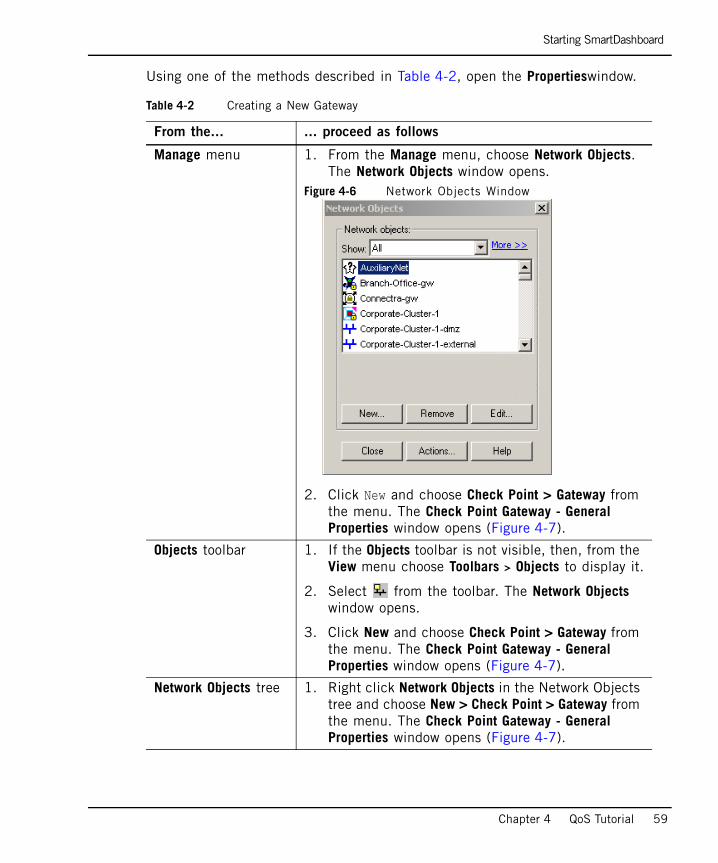
Using one of the methods described in Table 4-2, open the Propertieswindow.
Table 4-2 Creating a New Gateway
From the... ... proceed as follows
Manage menu 1. From the Manage menu, choose Network Objects. The Network Objects window opens.
Figure 4-6 Network Objects Window
2. Click New and choose Check Point > Gateway from the menu. The Check Point Gateway - General Properties window opens (Figure 4-7).
Objects toolbar 1. If the Objects toolbar is not visible, then, from the View menu choose Toolbars > Objects to display it.
2. Select from the toolbar. The Network Objects window opens.
3. Click New and choose Check Point > Gateway from the menu. The Check Point Gateway - General Properties window opens (Figure 4-7).
Network Objects tree 1. Right click Network Objects in the Network Objects tree and choose New > Check Point > Gateway from the menu. The Check Point Gateway - General Properties window opens (Figure 4-7).
Starting SmartDashboard
60
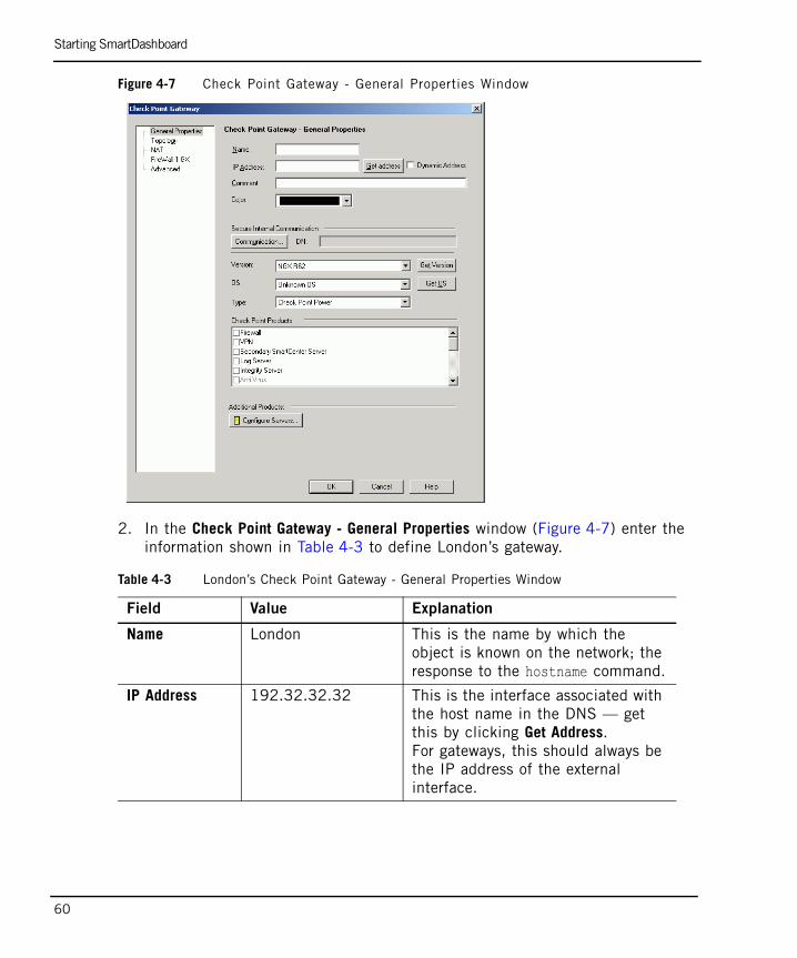
Figure 4-7 Check Point Gateway - General Properties Window
2. In the Check Point Gateway - General Properties window (Figure 4-7) enter the information shown in Table 4-3 to define London’s gateway.
Table 4-3 London’s Check Point Gateway - General Properties Window
Field Value Explanation
Name London This is the name by which the object is known on the network; the response to the hostname command.
IP Address 192.32.32.32 This is the interface associated with the host name in the DNS — get this by clicking Get Address.For gateways, this should always be the IP address of the external interface.
Starting SmartDashboard
Chapter 4 QoS Tutorial 61
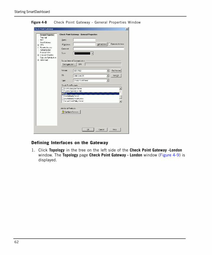
The Check Point Gateway - General Properties window now has the information shown in Figure 4-8 on page 62.
Comment QoS gateway (gateway)
This is the text that is displayed at the bottom of the Network Objects window when this object is selected
Check Point Products
• Select the Version from the drop-down list.
• Check VPN-1 Power (if needed), FireWall-1and QoS.
These settings specify the Check Point products installed on London, and their version number.QoS must be installed on any gateway on which a QoS gateway is installed.Note that if multiple Check Point products are installed on a machine, they must all be the same version number.
SIC Establishes a secure communication channel between Check Point gateways.
Table 4-3 London’s Check Point Gateway - General Properties Window
Field Value Explanation
Starting SmartDashboard
62
Figure 4-8 Check Point Gateway - General Properties Window
Defining Interfaces on the Gateway
1. Click Topology in the tree on the left side of the Check Point Gateway -London window. The Topology page Check Point Gateway - London window (Figure 4-9) is displayed.
Starting SmartDashboard
Chapter 4 QoS Tutorial 63
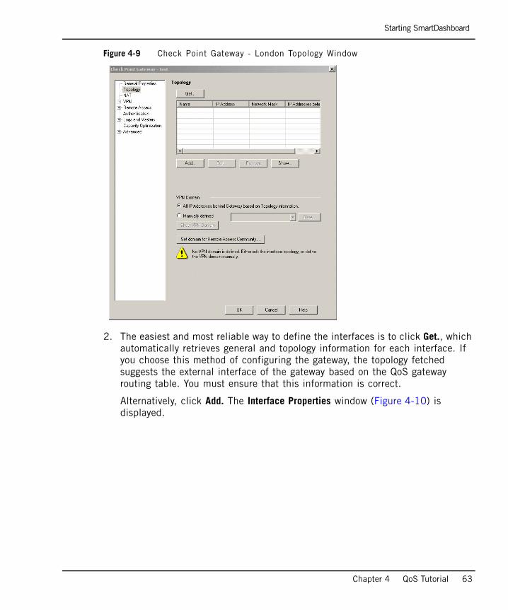
Figure 4-9 Check Point Gateway - London Topology Window
2. The easiest and most reliable way to define the interfaces is to click Get., which automatically retrieves general and topology information for each interface. If you choose this method of configuring the gateway, the topology fetched suggests the external interface of the gateway based on the QoS gateway routing table. You must ensure that this information is correct.
Alternatively, click Add. The Interface Properties window (Figure 4-10) is displayed.
Starting SmartDashboard
64
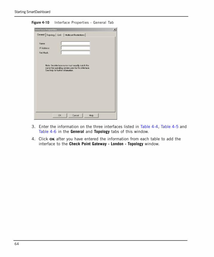
Figure 4-10 Interface Properties - General Tab
3. Enter the information on the three interfaces listed in Table 4-4, Table 4-5 and Table 4-6 in the General and Topology tabs of this window.
4. Click OK after you have entered the information from each table to add the interface to the Check Point Gateway - London - Topology window.
Starting SmartDashboard
Chapter 4 QoS Tutorial 65
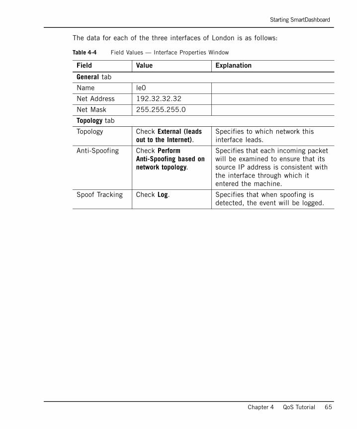
The data for each of the three interfaces of London is as follows:
Table 4-4 Field Values — Interface Properties Window
Field Value Explanation
General tab
Name le0
Net Address 192.32.32.32
Net Mask 255.255.255.0
Topology tab
Topology Check External (leads out to the Internet).
Specifies to which network this interface leads.
Anti-Spoofing Check Perform Anti-Spoofing based on network topology.
Specifies that each incoming packet will be examined to ensure that its source IP address is consistent with the interface through which it entered the machine.
Spoof Tracking Check Log. Specifies that when spoofing is detected, the event will be logged.
Starting SmartDashboard
66
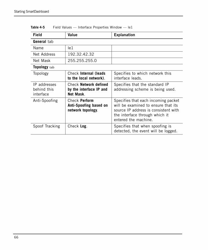
Table 4-5 Field Values — Interface Properties Window — le1
Field Value Explanation
General tab
Name le1
Net Address 192.32.42.32
Net Mask 255.255.255.0
Topology tab
Topology Check Internal (leads to the local network).
Specifies to which network this interface leads.
IP addresses behind this interface
Check Network defined by the interface IP and Net Mask.
Specifies that the standard IP addressing scheme is being used.
Anti-Spoofing Check Perform Anti-Spoofing based on network topology.
Specifies that each incoming packet will be examined to ensure that its source IP address is consistent with the interface through which it entered the machine.
Spoof Tracking Check Log. Specifies that when spoofing is detected, the event will be logged.
Starting SmartDashboard
Chapter 4 QoS Tutorial 67
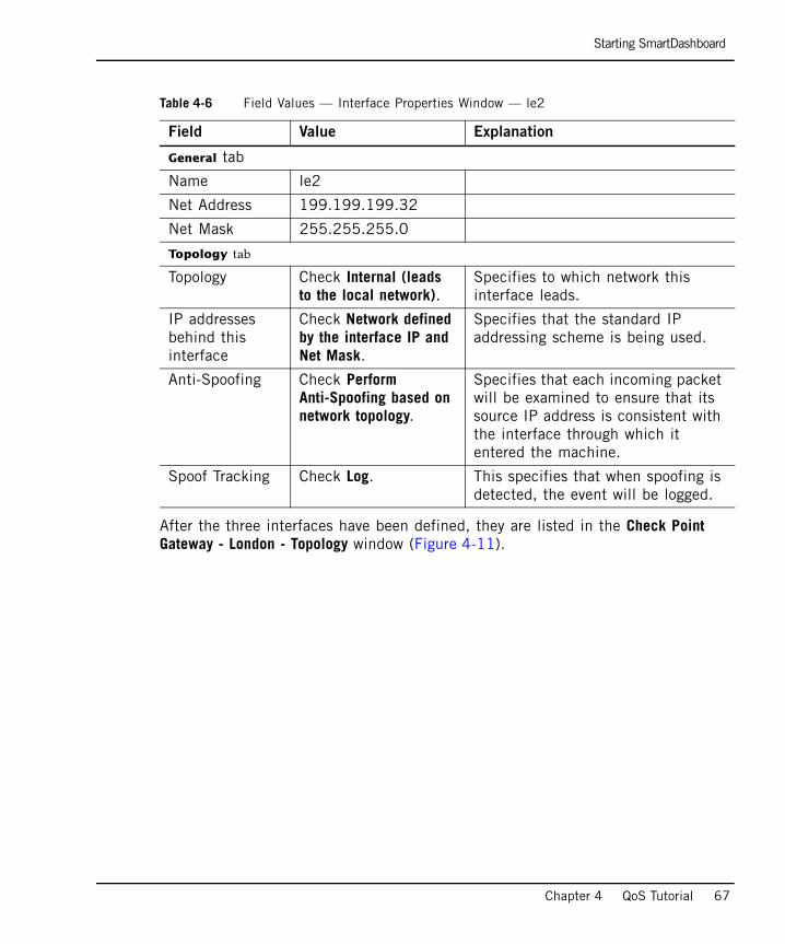
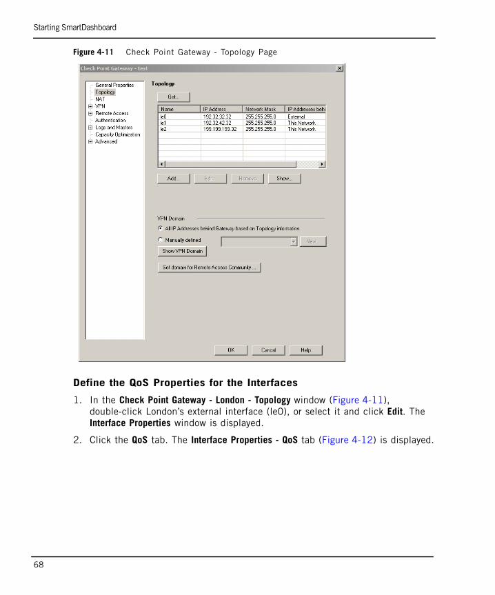
After the three interfaces have been defined, they are listed in the Check Point Gateway - London - Topology window (Figure 4-11).
Table 4-6 Field Values — Interface Properties Window — le2
Field Value Explanation
General tab
Name le2
Net Address 199.199.199.32
Net Mask 255.255.255.0
Topology tab
Topology Check Internal (leads to the local network).
Specifies to which network this interface leads.
IP addresses behind this interface
Check Network defined by the interface IP and Net Mask.
Specifies that the standard IP addressing scheme is being used.
Anti-Spoofing Check Perform Anti-Spoofing based on network topology.
Specifies that each incoming packet will be examined to ensure that its source IP address is consistent with the interface through which it entered the machine.
Spoof Tracking Check Log. This specifies that when spoofing is detected, the event will be logged.
Starting SmartDashboard
68
Figure 4-11 Check Point Gateway - Topology Page
Define the QoS Properties for the Interfaces
1. In the Check Point Gateway - London - Topology window (Figure 4-11), double-click London’s external interface (le0), or select it and click Edit. The Interface Properties window is displayed.
2. Click the QoS tab. The Interface Properties - QoS tab (Figure 4-12) is displayed.
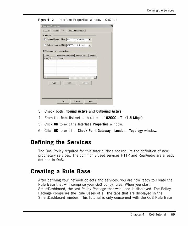
Defining the Services
Chapter 4 QoS Tutorial 69
Figure 4-12 Interface Properties Window - QoS tab
3. Check both Inbound Active and Outbound Active.
4. From the Rate list set both rates to 192000 - T1 (1.5 Mbps).
5. Click OK to exit the Interface Properties window.
6. Click OK to exit the Check Point Gateway - London - Topology window.
Defining the ServicesThe QoS Policy required for this tutorial does not require the definition of new proprietary services. The commonly used services HTTP and RealAudio are already defined in QoS.
Creating a Rule BaseAfter defining your network objects and services, you are now ready to create the Rule Base that will comprise your QoS policy rules. When you start SmartDashboard, the last Policy Package that was used is displayed. The Policy Package comprises the Rule Bases of all the tabs that are displayed in the SmartDashboard window. This tutorial is only concerned with the QoS Rule Base
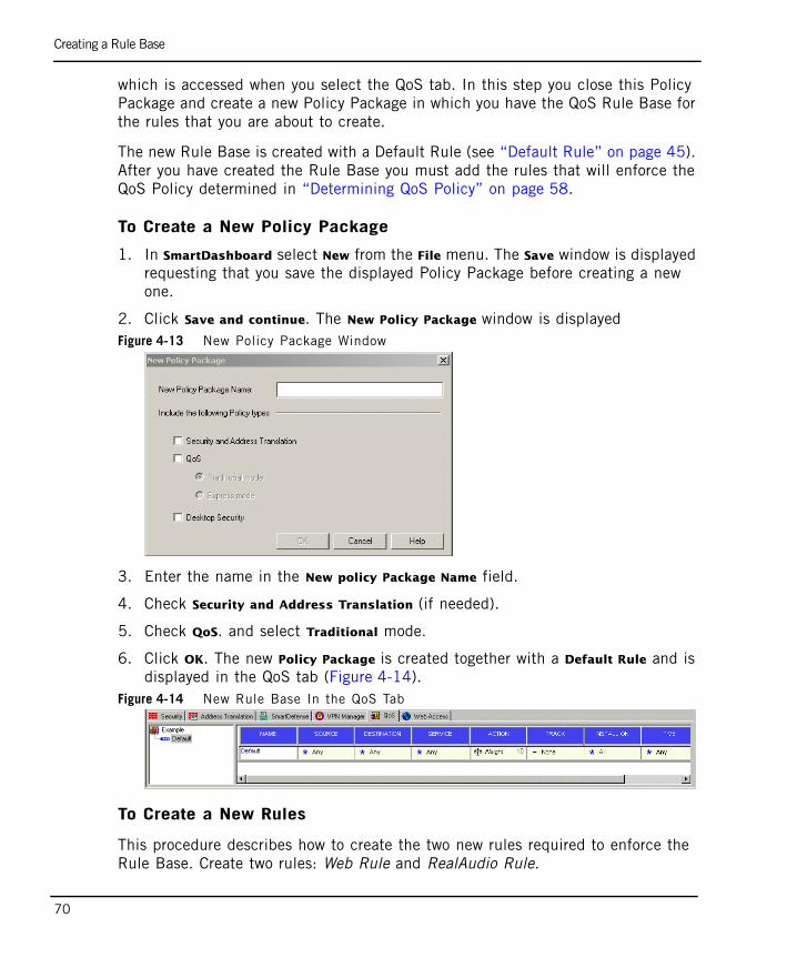
Creating a Rule Base
70
which is accessed when you select the QoS tab. In this step you close this Policy Package and create a new Policy Package in which you have the QoS Rule Base for the rules that you are about to create.
The new Rule Base is created with a Default Rule (see “Default Rule” on page 45). After you have created the Rule Base you must add the rules that will enforce the QoS Policy determined in “Determining QoS Policy” on page 58.
To Create a New Policy Package
1. In SmartDashboard select New from the File menu. The Save window is displayed requesting that you save the displayed Policy Package before creating a new one.
2. Click Save and continue. The New Policy Package window is displayedFigure 4-13 New Policy Package Window
3. Enter the name in the New policy Package Name field.
4. Check Security and Address Translation (if needed).
5. Check QoS. and select Traditional mode.
6. Click OK. The new Policy Package is created together with a Default Rule and is displayed in the QoS tab (Figure 4-14).
Figure 4-14 New Rule Base In the QoS Tab
To Create a New Rules
This procedure describes how to create the two new rules required to enforce the Rule Base. Create two rules: Web Rule and RealAudio Rule.
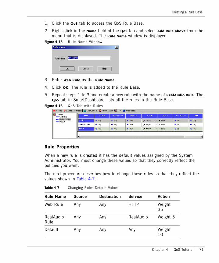
Creating a Rule Base
Chapter 4 QoS Tutorial 71
1. Click the QoS tab to access the QoS Rule Base.
2. Right-click in the Name field of the QoS tab and select Add Rule above from the menu that is displayed. The Rule Name window is displayed.
Figure 4-15 Rule Name Window
3. Enter Web Rule as the Rule Name.
4. Click OK. The rule is added to the Rule Base.
5. Repeat steps 1 to 3 and create a new rule with the name of RealAudio Rule. The QoS tab in SmartDashboard lists all the rules in the Rule Base.
Figure 4-16 QoS Tab with Rules
Rule Properties
When a new rule is created it has the default values assigned by the System Administrator. You must change these values so that they correctly reflect the policies you want.
The next procedure describes how to change these rules so that they reflect the values shown in Table 4-7.
Table 4-7 Changing Rules Default Values
Rule Name Source Destination Service Action
Web Rule Any Any HTTP Weight 35
RealAudio Rule
Any Any RealAudio Weight 5
Default Any Any Any Weight 10
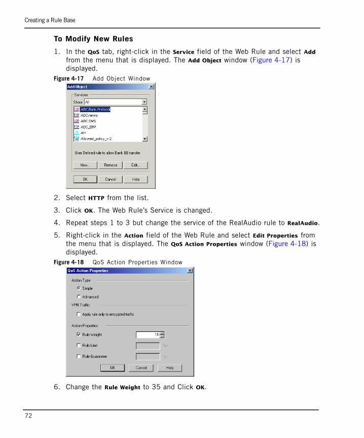
Creating a Rule Base
72
To Modify New Rules
1. In the QoS tab, right-click in the Service field of the Web Rule and select Add from the menu that is displayed. The Add Object window (Figure 4-17) is displayed.
Figure 4-17 Add Object Window
2. Select HTTP from the list.
3. Click OK. The Web Rule’s Service is changed.
4. Repeat steps 1 to 3 but change the service of the RealAudio rule to RealAudio.
5. Right-click in the Action field of the Web Rule and select Edit Properties from the menu that is displayed. The QoS Action Properties window (Figure 4-18) is displayed.
Figure 4-18 QoS Action Properties Window
6. Change the Rule Weight to 35 and Click OK.
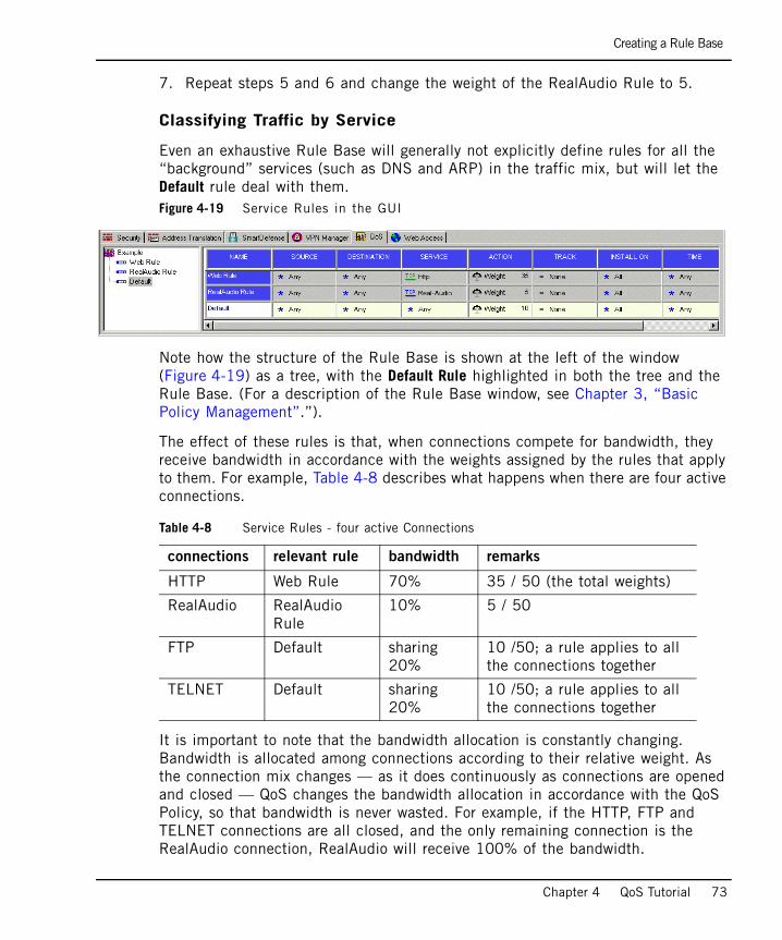
Creating a Rule Base
Chapter 4 QoS Tutorial 73
7. Repeat steps 5 and 6 and change the weight of the RealAudio Rule to 5.
Classifying Traffic by Service
Even an exhaustive Rule Base will generally not explicitly define rules for all the “background” services (such as DNS and ARP) in the traffic mix, but will let the Default rule deal with them.Figure 4-19 Service Rules in the GUI
Note how the structure of the Rule Base is shown at the left of the window (Figure 4-19) as a tree, with the Default Rule highlighted in both the tree and the Rule Base. (For a description of the Rule Base window, see Chapter 3, “Basic Policy Management”.”).
The effect of these rules is that, when connections compete for bandwidth, they receive bandwidth in accordance with the weights assigned by the rules that apply to them. For example, Table 4-8 describes what happens when there are four active connections.
It is important to note that the bandwidth allocation is constantly changing. Bandwidth is allocated among connections according to their relative weight. As the connection mix changes — as it does continuously as connections are opened and closed — QoS changes the bandwidth allocation in accordance with the QoS Policy, so that bandwidth is never wasted. For example, if the HTTP, FTP and TELNET connections are all closed, and the only remaining connection is the RealAudio connection, RealAudio will receive 100% of the bandwidth.
Table 4-8 Service Rules - four active Connections
connections relevant rule bandwidth remarks
HTTP Web Rule 70% 35 / 50 (the total weights)
RealAudio RealAudio Rule
10% 5 / 50
FTP Default sharing 20%
10 /50; a rule applies to all the connections together
TELNET Default sharing 20%
10 /50; a rule applies to all the connections together
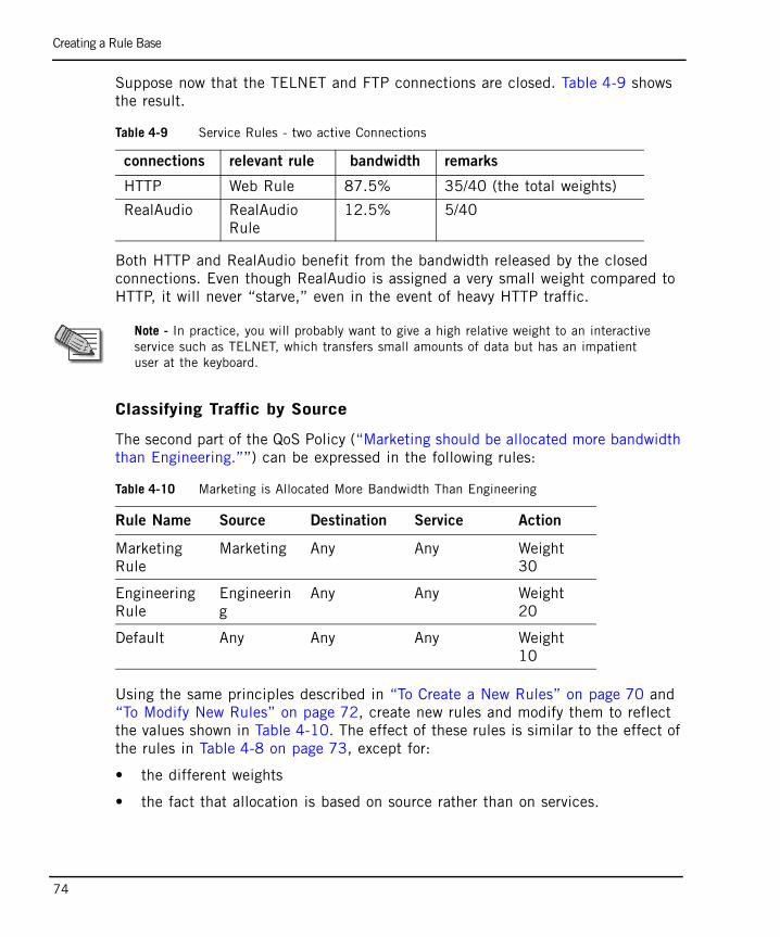
Creating a Rule Base
74
Suppose now that the TELNET and FTP connections are closed. Table 4-9 shows the result.
Both HTTP and RealAudio benefit from the bandwidth released by the closed connections. Even though RealAudio is assigned a very small weight compared to HTTP, it will never “starve,” even in the event of heavy HTTP traffic.
Classifying Traffic by Source
The second part of the QoS Policy (“Marketing should be allocated more bandwidth than Engineering.””) can be expressed in the following rules:
Using the same principles described in “To Create a New Rules” on page 70 and “To Modify New Rules” on page 72, create new rules and modify them to reflect the values shown in Table 4-10. The effect of these rules is similar to the effect of the rules in Table 4-8 on page 73, except for:
• the different weights
• the fact that allocation is based on source rather than on services.
Table 4-9 Service Rules - two active Connections
connections relevant rule bandwidth remarks
HTTP Web Rule 87.5% 35/40 (the total weights)
RealAudio RealAudio Rule
12.5% 5/40
Note - In practice, you will probably want to give a high relative weight to an interactive service such as TELNET, which transfers small amounts of data but has an impatient user at the keyboard.
Table 4-10 Marketing is Allocated More Bandwidth Than Engineering
Rule Name Source Destination Service Action
Marketing Rule
Marketing Any Any Weight 30
Engineering Rule
Engineering
Any Any Weight 20
Default Any Any Any Weight 10
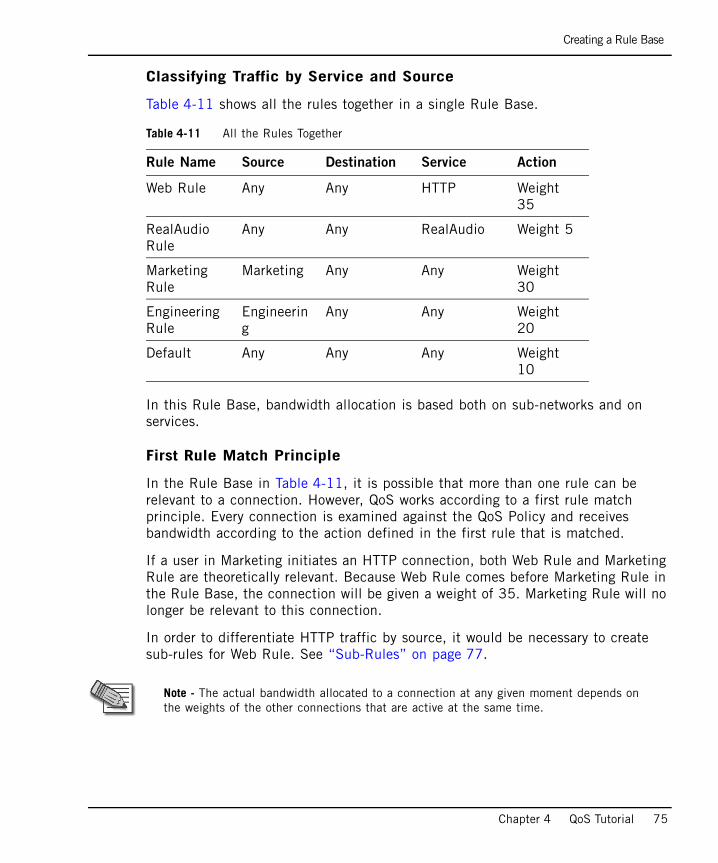
Creating a Rule Base
Chapter 4 QoS Tutorial 75
Classifying Traffic by Service and Source
Table 4-11 shows all the rules together in a single Rule Base.
In this Rule Base, bandwidth allocation is based both on sub-networks and on services.
First Rule Match Principle
In the Rule Base in Table 4-11, it is possible that more than one rule can be relevant to a connection. However, QoS works according to a first rule match principle. Every connection is examined against the QoS Policy and receives bandwidth according to the action defined in the first rule that is matched.
If a user in Marketing initiates an HTTP connection, both Web Rule and Marketing Rule are theoretically relevant. Because Web Rule comes before Marketing Rule in the Rule Base, the connection will be given a weight of 35. Marketing Rule will no longer be relevant to this connection.
In order to differentiate HTTP traffic by source, it would be necessary to create sub-rules for Web Rule. See “Sub-Rules” on page 77.
Table 4-11 All the Rules Together
Rule Name Source Destination Service Action
Web Rule Any Any HTTP Weight 35
RealAudio Rule
Any Any RealAudio Weight 5
Marketing Rule
Marketing Any Any Weight 30
Engineering Rule
Engineering
Any Any Weight 20
Default Any Any Any Weight 10
Note - The actual bandwidth allocated to a connection at any given moment depends on the weights of the other connections that are active at the same time.
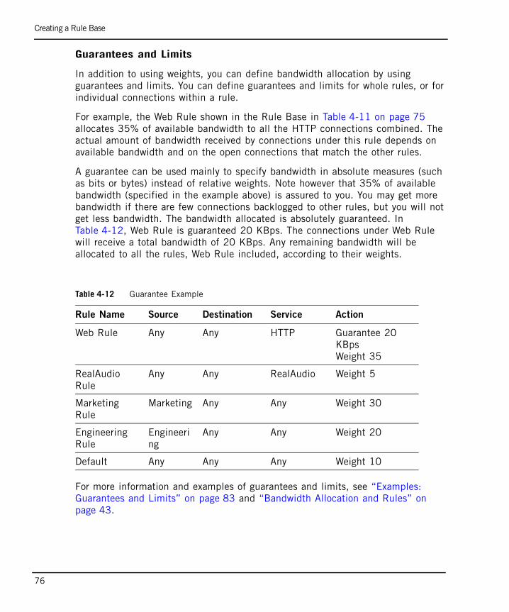
Creating a Rule Base
76
Guarantees and Limits
In addition to using weights, you can define bandwidth allocation by using guarantees and limits. You can define guarantees and limits for whole rules, or for individual connections within a rule.
For example, the Web Rule shown in the Rule Base in Table 4-11 on page 75 allocates 35% of available bandwidth to all the HTTP connections combined. The actual amount of bandwidth received by connections under this rule depends on available bandwidth and on the open connections that match the other rules.
A guarantee can be used mainly to specify bandwidth in absolute measures (such as bits or bytes) instead of relative weights. Note however that 35% of available bandwidth (specified in the example above) is assured to you. You may get more bandwidth if there are few connections backlogged to other rules, but you will not get less bandwidth. The bandwidth allocated is absolutely guaranteed. In Table 4-12, Web Rule is guaranteed 20 KBps. The connections under Web Rule will receive a total bandwidth of 20 KBps. Any remaining bandwidth will be allocated to all the rules, Web Rule included, according to their weights.
For more information and examples of guarantees and limits, see “Examples: Guarantees and Limits” on page 83 and “Bandwidth Allocation and Rules” on page 43.
Table 4-12 Guarantee Example
Rule Name Source Destination Service Action
Web Rule Any Any HTTP Guarantee 20 KBpsWeight 35
RealAudio Rule
Any Any RealAudio Weight 5
Marketing Rule
Marketing Any Any Weight 30
Engineering Rule
Engineering
Any Any Weight 20
Default Any Any Any Weight 10
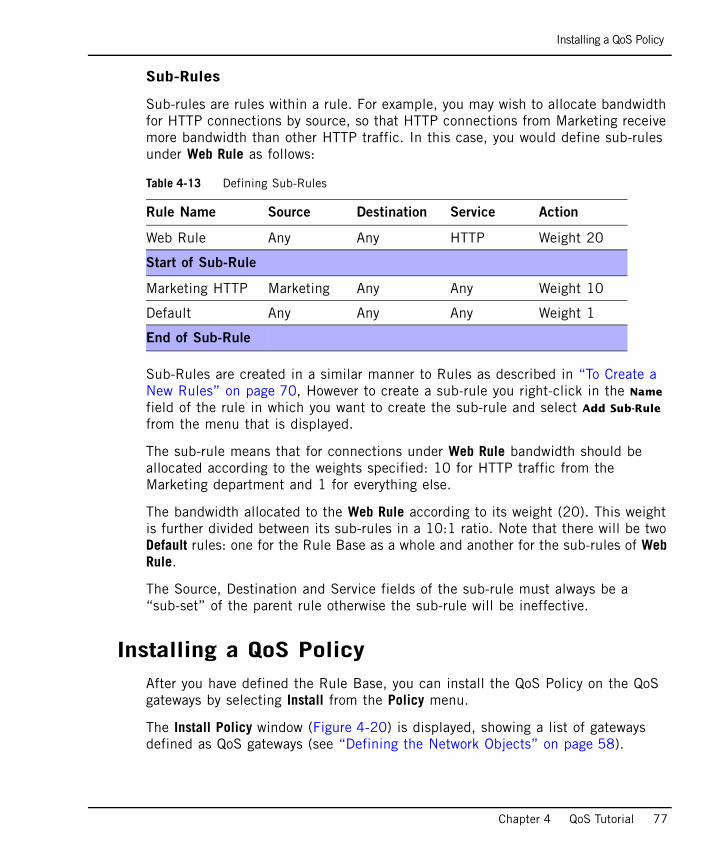
Installing a QoS Policy
Chapter 4 QoS Tutorial 77
Sub-Rules
Sub-rules are rules within a rule. For example, you may wish to allocate bandwidth for HTTP connections by source, so that HTTP connections from Marketing receive more bandwidth than other HTTP traffic. In this case, you would define sub-rules under Web Rule as follows:
Sub-Rules are created in a similar manner to Rules as described in “To Create a New Rules” on page 70, However to create a sub-rule you right-click in the Name field of the rule in which you want to create the sub-rule and select Add Sub-Rule from the menu that is displayed.
The sub-rule means that for connections under Web Rule bandwidth should be allocated according to the weights specified: 10 for HTTP traffic from the Marketing department and 1 for everything else.
The bandwidth allocated to the Web Rule according to its weight (20). This weight is further divided between its sub-rules in a 10:1 ratio. Note that there will be two Default rules: one for the Rule Base as a whole and another for the sub-rules of Web Rule.
The Source, Destination and Service fields of the sub-rule must always be a “sub-set” of the parent rule otherwise the sub-rule will be ineffective.
Installing a QoS PolicyAfter you have defined the Rule Base, you can install the QoS Policy on the QoS gateways by selecting Install from the Policy menu.
The Install Policy window (Figure 4-20) is displayed, showing a list of gateways defined as QoS gateways (see “Defining the Network Objects” on page 58).
Table 4-13 Defining Sub-Rules
Rule Name Source Destination Service Action
Web Rule Any Any HTTP Weight 20
Start of Sub-Rule
Marketing HTTP Marketing Any Any Weight 10
Default Any Any Any Weight 1
End of Sub-Rule
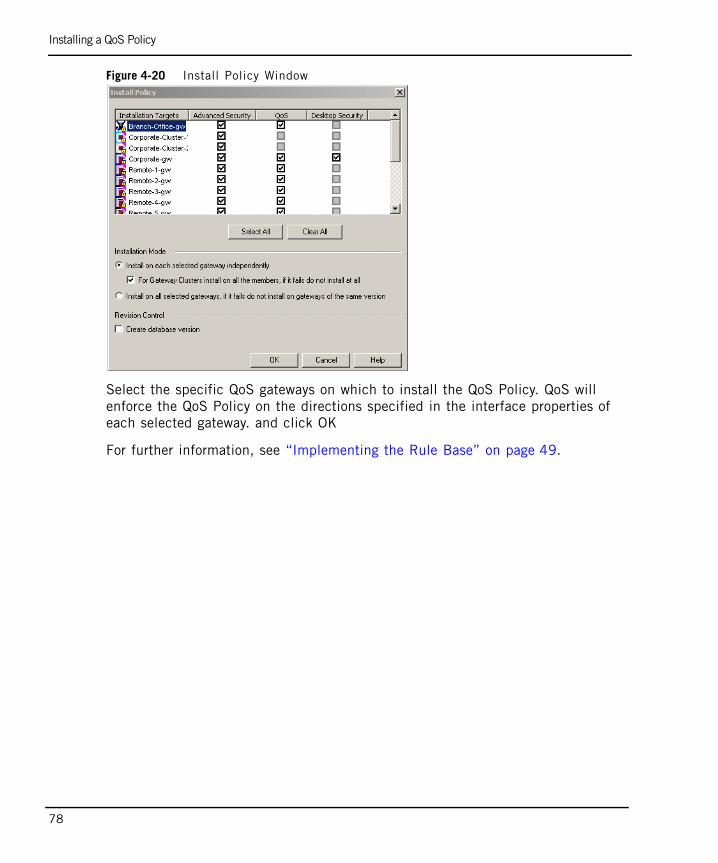
Installing a QoS Policy
78
Figure 4-20 Install Policy Window
Select the specific QoS gateways on which to install the QoS Policy. QoS will enforce the QoS Policy on the directions specified in the interface properties of each selected gateway. and click OK
For further information, see “Implementing the Rule Base” on page 49.
Conclusion
Chapter 4 QoS Tutorial 79
ConclusionYou have now completed all the steps that were required to install the network described in Figure 4-1 on page 52, and to define the Rule Base that will implement the required policy QoS policy.
As a result, you should have a much better understanding of how QoS policy can be implemented using QoS. It is strongly recommended however that you now spend some time and refer to Chapter 6, “Managing QoS”” for further information.

Conclusion
80
81
Chapter 5Advanced QoS Policy Management
In This Chapter
Overview page 82
Examples: Guarantees and Limits page 83
Differentiated Services (DiffServ) page 89
Low Latency Queuing page 91
Authenticated QoS page 99
Citrix MetaFrame Support page 100
Load Sharing page 102
Overview
82
OverviewThis chapter describes the more advanced QoS policy management procedures that enable you to refine the basic QoS policies described in Chapter 3, “Basic Policy Management””.
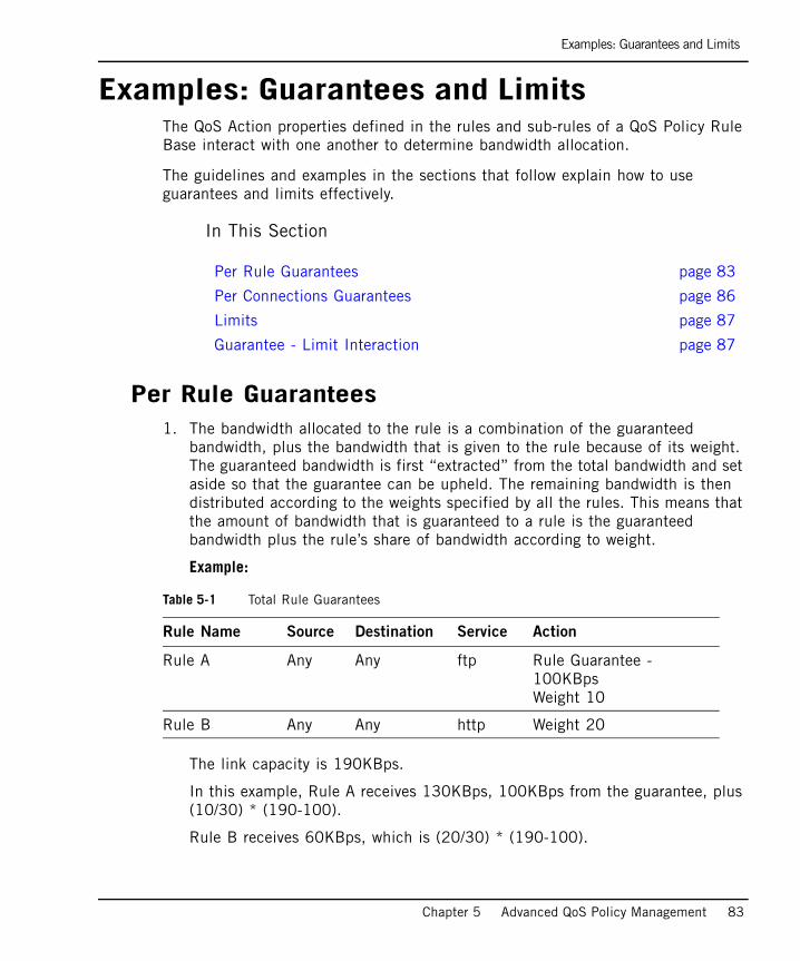
Examples: Guarantees and Limits
Chapter 5 Advanced QoS Policy Management 83
Examples: Guarantees and LimitsThe QoS Action properties defined in the rules and sub-rules of a QoS Policy Rule Base interact with one another to determine bandwidth allocation.
The guidelines and examples in the sections that follow explain how to use guarantees and limits effectively.
In This Section
Per Rule Guarantees1. The bandwidth allocated to the rule is a combination of the guaranteed
bandwidth, plus the bandwidth that is given to the rule because of its weight. The guaranteed bandwidth is first “extracted” from the total bandwidth and set aside so that the guarantee can be upheld. The remaining bandwidth is then distributed according to the weights specified by all the rules. This means that the amount of bandwidth that is guaranteed to a rule is the guaranteed bandwidth plus the rule’s share of bandwidth according to weight.
Example:
The link capacity is 190KBps.
In this example, Rule A receives 130KBps, 100KBps from the guarantee, plus (10/30) * (190-100).
Rule B receives 60KBps, which is (20/30) * (190-100).
Per Rule Guarantees page 83
Per Connections Guarantees page 86
Limits page 87
Guarantee - Limit Interaction page 87
Table 5-1 Total Rule Guarantees
Rule Name Source Destination Service Action
Rule A Any Any ftp Rule Guarantee - 100KBpsWeight 10
Rule B Any Any http Weight 20
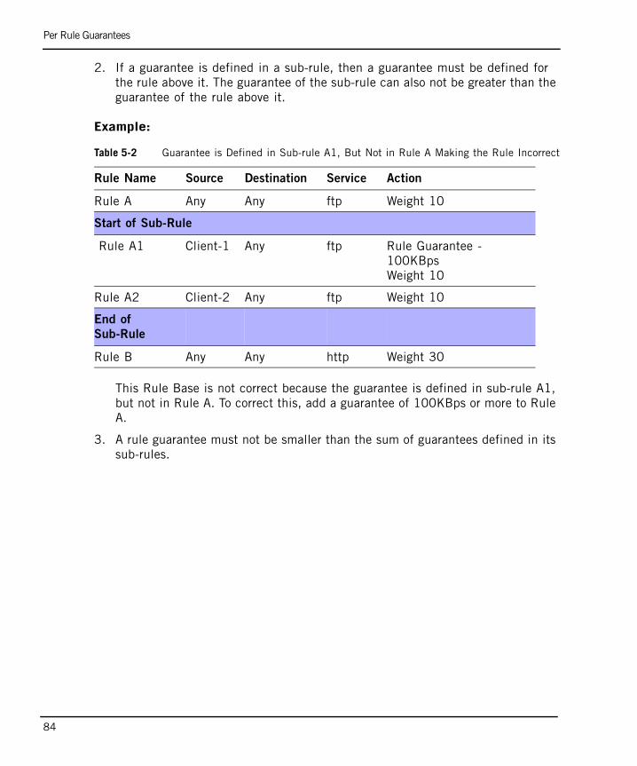
Per Rule Guarantees
84
2. If a guarantee is defined in a sub-rule, then a guarantee must be defined for the rule above it. The guarantee of the sub-rule can also not be greater than the guarantee of the rule above it.
Example:
This Rule Base is not correct because the guarantee is defined in sub-rule A1, but not in Rule A. To correct this, add a guarantee of 100KBps or more to Rule A.
3. A rule guarantee must not be smaller than the sum of guarantees defined in its sub-rules.
Table 5-2 Guarantee is Defined in Sub-rule A1, But Not in Rule A Making the Rule Incorrect
Rule Name Source Destination Service Action
Rule A Any Any ftp Weight 10
Start of Sub-Rule
Rule A1 Client-1 Any ftp Rule Guarantee - 100KBpsWeight 10
Rule A2 Client-2 Any ftp Weight 10
End of
Sub-Rule
Rule B Any Any http Weight 30
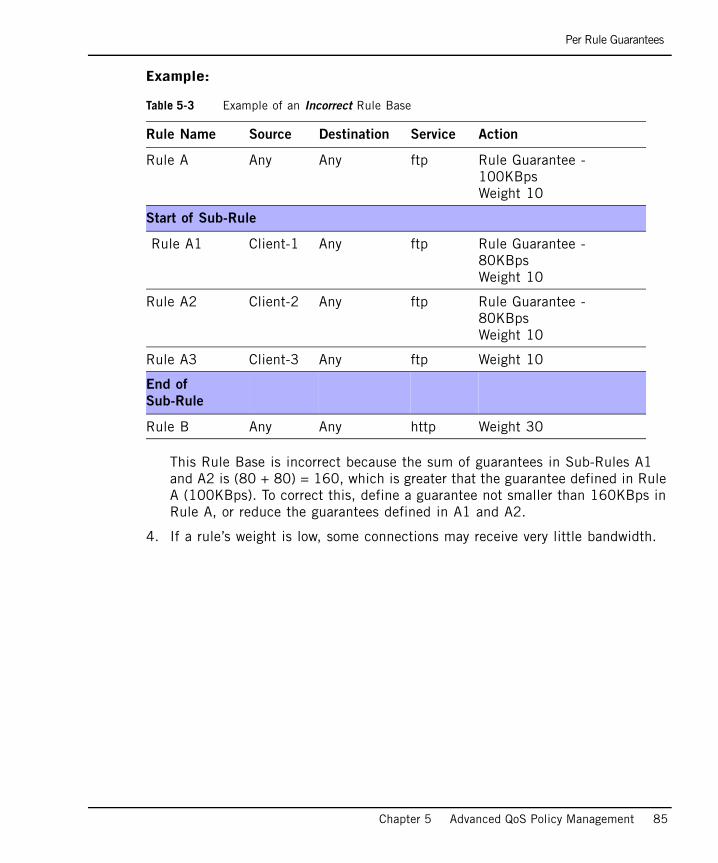
Per Rule Guarantees
Chapter 5 Advanced QoS Policy Management 85
Example:
This Rule Base is incorrect because the sum of guarantees in Sub-Rules A1 and A2 is (80 + 80) = 160, which is greater that the guarantee defined in Rule A (100KBps). To correct this, define a guarantee not smaller than 160KBps in Rule A, or reduce the guarantees defined in A1 and A2.
4. If a rule’s weight is low, some connections may receive very little bandwidth.
Table 5-3 Example of an Incorrect Rule Base
Rule Name Source Destination Service Action
Rule A Any Any ftp Rule Guarantee - 100KBpsWeight 10
Start of Sub-Rule
Rule A1 Client-1 Any ftp Rule Guarantee - 80KBpsWeight 10
Rule A2 Client-2 Any ftp Rule Guarantee - 80KBpsWeight 10
Rule A3 Client-3 Any ftp Weight 10
End of
Sub-Rule
Rule B Any Any http Weight 30
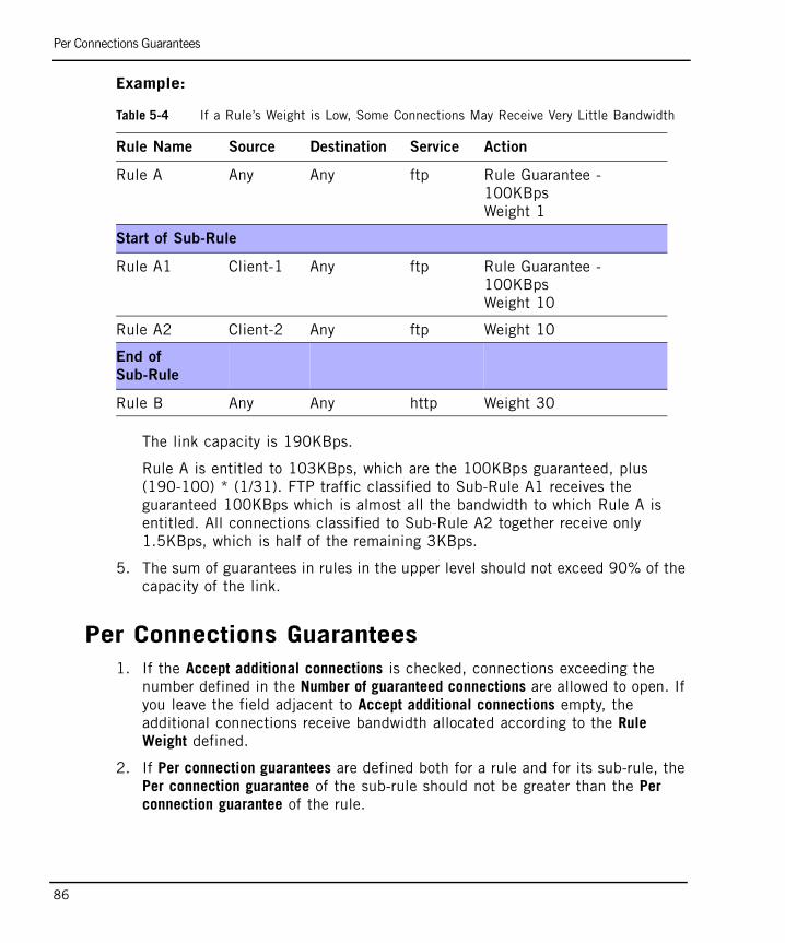
Per Connections Guarantees
86
Example:
The link capacity is 190KBps.
Rule A is entitled to 103KBps, which are the 100KBps guaranteed, plus (190-100) * (1/31). FTP traffic classified to Sub-Rule A1 receives the guaranteed 100KBps which is almost all the bandwidth to which Rule A is entitled. All connections classified to Sub-Rule A2 together receive only 1.5KBps, which is half of the remaining 3KBps.
5. The sum of guarantees in rules in the upper level should not exceed 90% of the capacity of the link.
Per Connections Guarantees1. If the Accept additional connections is checked, connections exceeding the
number defined in the Number of guaranteed connections are allowed to open. If you leave the field adjacent to Accept additional connections empty, the additional connections receive bandwidth allocated according to the Rule Weight defined.
2. If Per connection guarantees are defined both for a rule and for its sub-rule, the Per connection guarantee of the sub-rule should not be greater than the Per connection guarantee of the rule.
Table 5-4 If a Rule’s Weight is Low, Some Connections May Receive Very Little Bandwidth
Rule Name Source Destination Service Action
Rule A Any Any ftp Rule Guarantee - 100KBpsWeight 1
Start of Sub-Rule
Rule A1 Client-1 Any ftp Rule Guarantee - 100KBpsWeight 10
Rule A2 Client-2 Any ftp Weight 10
End of
Sub-Rule
Rule B Any Any http Weight 30
Limits
Chapter 5 Advanced QoS Policy Management 87
When such a Rule Base is defined, a connection classified to the sub-rule receives the Per connection guarantee that is defined in the sub-rule. If a sub-rule does not have a Per connection guarantee, it still receives the Per connection guarantee defined in the parent rule.
Limits1. If both a Rule Limit and a Per connection limit are defined for a rule, the Per
connection limit must not be greater than the Rule Limit.
2. If a limit is defined in a rule with sub-rules, and limits are defined in all the sub-rules, the rule limit should not be greater than the sum of limits defined in the sub-rules.
Having a rule limit that is greater than the sum of limits defined in the sub-rules is never necessary, because it is not possible to allocate more bandwidth to a rule than the bandwidth determined by the sum of the limits of its sub-rules.
Guarantee - Limit Interaction1. If a Rule Limit and a Guarantee per rule are defined in a rule, then the limit
should not be smaller than the guarantee.
2. If both a Limit and a Guarantee are defined in a rule, and the Limit is equal to the Guarantee, connections may receive no bandwidth, as in the following examples:
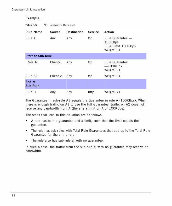
Guarantee - Limit Interaction
88
Example:
The Guarantee in sub-rule A1 equals the Guarantee in rule A (100KBps). When there is enough traffic on A1 to use the full Guarantee, traffic on A2 does not receive any bandwidth from A (there is a limit on A of 100KBps).
The steps that lead to this situation are as follows:
• A rule has both a guarantee and a limit, such that the limit equals the guarantee.
• The rule has sub-rules with Total Rule Guarantees that add up to the Total Rule Guarantee for the entire rule.
• The rule also has sub-rule(s) with no guarantee.
In such a case, the traffic from the sub-rule(s) with no guarantee may receive no bandwidth.
Table 5-5 No Bandwidth Received
Rule Name Source Destination Service Action
Rule A Any Any ftp Rule Guarantee — 100KBpsRule Limit 100KBpsWeight 10
Start of Sub-Rule
Rule A1 Client-1 Any ftp Rule Guarantee —100KBpsWeight 10
Rule A2 Client-2 Any ftp Weight 10
End of
Sub-Rule
Rule B Any Any http Weight 30
Differentiated Services (DiffServ)
Chapter 5 Advanced QoS Policy Management 89
Differentiated Services (DiffServ)In This Section
OverviewDiffServ is an architecture for providing different types or levels of service for network traffic. Packets are marked in the IP header TOS byte, inside the enterprise network as belonging to a certain Class of Service, or QoS Class. These packets are then granted priority on the public network.
DiffServ markings have meaning on the public network, not inside the enterprise network. (Effective implementation of DiffServ requires that packet markings be recognized on all public network segments.)
DiffServ Markings for IPSec PacketsWhen DiffServ markings are used for IPSec packets, the DiffServ mark can be copied from one location to another in one of two ways:
• :ipsec.copy_TOS_to_inner — The DiffServ mark is copied from the IPSec header to the IP header of the original packet after decapsulation/decryption.
• :ipsec.copy_TOS_to_outer — The DiffServ mark is copied from the original packet’s IP header to the IPSec header of the encrypted packet after encapsulation.
This property should be set, per QoS gateway, in $FWDIR/conf/objects_5_0.c.
The default setting is:
:ipsec.copy_TOS_to_inner (false)
:ipsec.copy_TOS_to_outer (true)
Overview page 89
DiffServ Markings for IPSec Packets page 89
Interaction Between DiffServ Rules and Other Rules page 90
Interaction Between DiffServ Rules and Other Rules
90
Interaction Between DiffServ Rules and Other RulesA DiffServ rule specifies not only a QoS Class, but also a weight, in the same way that other QoS Policy Rules do. These weights are enforced only on the interfaces on which the rules of this class are installed.
For example, suppose a DiffServ rule specifies a weight of 50 for FTP connections. That rule is installed only on the interfaces for which the QoS Class is defined. On other interfaces, the rule is not installed and FTP connections routed through those other interfaces do not receive the weight specified in the rule. To specify a weight for all FTP connections, add a rule under “Best Effort.”
DiffServ rules can be installed only on interfaces for which the relevant QoS Class has been defined in the QoS tab of the Interface Properties window (FIGURE 0-3 on page 112). “Best Effort” rules (that is, non-DiffServ rules) can be installed on all interfaces of gateways with QoS gateways installed. Only rules installed on the same interface interact with each other.
Low Latency Queuing
Chapter 5 Advanced QoS Policy Management 91
Low Latency QueuingIn This Section
OverviewFor most traffic on the Web (including most TCP protocols), the WFQ (Weighted Fair Queuing, see “Intelligent Queuing Engine” on page 29) paradigm is adequate. This means that packets reaching QoS are put in queues and forwarded according to the interface bandwidth and the priority of the matching rule. Using this standard policy, QoS avoids dropping packets as often as possible, because such drops may adversely affect TCP. Avoiding drops, however, means holding (possibly long) queues, which may lead to non-negligible delays.
For some types of traffic, such as voice and video, bounding this delay is important. Long queues are inadequate for these types of traffic because they lead to substantial delay. Fortunately, for most “delay sensitive” applications, there is no need to drop packets from queues in order to keep them short.
Instead, the fact that the streams of these applications have a known, bounded bit rate can be utilized. If QoS is configured to forward as much traffic as the stream delivers, then only a small number of packets accumulate in the queues and delay is negligible.
QoS Low Latency Queuing makes it possible to define special Classes of Service for “delay sensitive” applications like voice and video. Rules under these classes can be used together with other rules in the QoS Policy Rule Base. Low Latency classes require you to specify the maximal delay that is tolerated and a Constant Bit Rate. QoS then guarantees that traffic matching rules of this type is forwarded within the limits of the bounded delay.
Low Latency ClassesFor information on installing Low Latency Classes, see “Low Latency Classes” on page 91.
Overview page 91
Low Latency Classes page 91
Interaction between Low Latency and Other Rule Properties page 96
When to Use Low Latency Queuing page 97
Low Latency versus DiffServ page 98
Low Latency Classes
92
For each Low Latency class defined on an interface, a constant bit rate and maximal delay should be specified for active directions. QoS checks packets matched to Low Latency class rules to make sure they have not been delayed for longer than their maximal delay permits. If the maximal delay of a packet has been exceeded, it is dropped. Otherwise, it is transmitted at the defined constant bit rate for the Low Latency class to which it belongs.
If the Constant Bit Rate of the class is defined correctly (meaning that it is not smaller than the expected arrival rate of the matched traffic), packets are not dropped (provided that the delay exceeds some minimum, see “Computing Maximal Delay” on page 93). On the other hand, when the arrival rate is higher than the specified Constant Bit Rate, packets exceeding this constant rate are dropped to ensure that those transmitted are within the maximal delay limitations.
Low Latency Class PrioritiesIn most cases, one Low Latency class is sufficient to serve all bounded delay traffic. In some cases, however, the user may need to define more than one Low Latency class. For this purpose, Low Latency classes are assigned one out of five priority levels (not including the Expedited Forwarding class, see “Low Latency versus DiffServ” on page 98). These priority levels are relative to other Low Latency classes.
It is advisable to define more than one Low Latency class if different types of traffic require different maximal delays.
The class with the lower maximal delay should get a higher priority than the class with the higher delay. The reason for this is that when two packets are ready to be forwarded, one for each Low Latency class, the packet from the higher priority class is forwarded first. The remaining packet (from the lower class) then encounters greater delay. This implies that the maximal delay that can be set for a Low Latency class depends on the Low Latency classes of higher priority.
Other Low Latency classes can affect the delay incurred by a class and therefore must be taken into consideration when determining the minimal delay that is feasible for the class. This is best done by initially setting the priorities for all Low Latency classes according to maximal delay, and then defining the classes according to descending priority. When you define class two, for example, class one should already be defined.
Note - The maximal delay set for a Low Latency class is an upper limit. This means that packets matching the class are always forwarded with a delay not greater, but often smaller, than specified.
Low Latency Classes
Chapter 5 Advanced QoS Policy Management 93
For more information on the effects of class priority on computing maximal delay, see “Computing Maximal Delay” on page 93.
Logging LLQ InformationSmartView Tracker enables you to log extensive information for all aspects of LLQ. For more information, see “SmartView Tracker” on page 163.
Computing the Correct Constant Bit Rate and Maximal Delay
Limits on Constant Bit Rate
For each direction of an interface (inbound and outbound), the sum of the constant bit rates of all the Low Latency classes cannot exceed 20% of the total designated bandwidth rate. The 20% limit is set to ensure that “Best Effort” traffic does not suffer substantial delay and jitter as a result of the existing Low Latency class(es).
Computing Constant Bit Rate
To compute the Constant Bit Rate of a Low Latency class, you should know the bit rate of a single application stream in traffic that matches the class and the number of expected streams that are simultaneously opened. The Constant Bit Rate of the class should be the bit rate of a single application, multiplied by the expected number of simultaneous streams.
If the number of streams exceeds the number you expected when you set the Constant Bit Rate, then the total incoming bit rate exceeds the Constant Bit Rate, and many drops occur. You can avoid this situation by limiting the number of concurrent streams. For more information, see “Ensuring that Constant Bit Rate is Not Exceeded (Preventing Unwanted Drops)” on page 96.
Computing Maximal Delay
To compute the maximal delay of a Low Latency class, you should take into account both the maximal delay that streams matching the class can tolerate in QoS and the minimal delay that QoS can guarantee this stream.
Note - Unlike bandwidth allocated by a Guarantee, the constant bit rate allocated to a Low Latency class on an interface in a given direction is not increased in the event that more bandwidth is available.
Low Latency Classes
94
It is important not to define a maximal delay that is too small, which may lead to unwanted drops. The delay value defined for a class determines the number of packets that can be queued in the Low Latency queue before drops begin to occur. The smaller the delay, the shorter the queue. Therefore, an insufficient maximal delay may cause packets to be dropped before they have the chance to be forwarded. It is advisable to allow for at least several packets to be queued, as explained in the steps below.
If you are using Check Point SmartView Tracker, it is recommended to use the default Class Maximal Delay defined in the LLQ log. In order to obtain this default number, you must first configure the correct Constant Bit Rate for the Class and you must give an estimation for the Class Maximal Delay. For more information, see “SmartView Tracker” on page 163. Alternately, you can set the Class Maximal Delay, as described in the steps that follow. If you use the following method you can set the delay of the class by obtaining estimates for the upper and lower bounds, and setting the delay to a value between the bounds:
1. Estimate the greatest delay that you can set for the class:
1. Refer to the technical details of the streaming application and find the delay that it can tolerate.
For voice applications, for example, it is commonly stated that the user starts to experience irregularities when the overall delay exceeds 150 ms.
2. Find or estimate the bound on the delay that your external network (commonly the WAN) imposes. Many Internet Service Providers publish Service Level Agreements (SLAs) that guarantee certain bounds on delay.
3. The maximal delay should be set at no more than the delay that the streaming application can tolerate minus the delay that the external network introduces.
This ensures that when the delay introduced by QoS is added to the delay introduced by the external network, and does not exceed the delay tolerated by the streaming application.
2. Estimate the smallest delay that you can set for the class:
1. Find the bit rate of the streaming application in the application properties, or using Check Point SmartView Monitoring (see SmartView Monitor Administration Guide).
Note - Even if you set the Constant Bit Rate of the class to accommodate multiple simultaneous streams, conduct the following calculations with the streaming rate of a single stream.
Low Latency Classes
Chapter 5 Advanced QoS Policy Management 95
2. Estimate the typical packet size in the stream. You can either find it in the application properties or monitor the traffic.
If you do not know the packet size, you can use the size of the MTU of the LAN behind QoS. For Ethernet, this number is 1500 Bytes.
3. Many LAN devices, including switches and NICs, introduce some burstiness to flows of constant bit rate by changing the delay between packets. For constant bit rate traffic generated in the LAN and going out to the WAN, it is therefore recommended to monitor the stream packets on the QoS gateway (on the internal interface that precedes QoS) to get an estimate of burst size.
4. If no burstiness is detected, the minimal delay of the class should be no smaller than:
This enables three packets to be held in the queue before drops can occur. (Note again that the bit rate should represent a single application, even if you set the Constant Bit Rate of the class to accommodate multiple streams.)
If burstiness is detected, set the minimal delay of the class to be at least:
3. The maximal delay that you choose for the class should be between the smallest delay (estimated in step 2 on page 94) and the greatest delay (estimated in step 1 on page 94). Setting it very close to either of these values is not recommended. However, if you expect the application to burst occasionally, or if you don’t know whether the application generates bursts at all, then you should set the delay close to the greatest value.
4. When you enter the maximal delay you calculated, you may get an error box containing the message “The inbound/outbound maximal delay of class... must be greater than... milliseconds.”
This can occur if the Class of Service that you define is not of the first priority (see “Low Latency Class Priorities” on page 92). The delay value displayed in the error message depends on the Low Latency classes of higher priority, and on interface speed.
Set the maximal delay to a value no smaller than the one printed in the message.
3 packet size×bit rate
-----------------------------------
burst size 1+( ) packet size×bit rate
---------------------------------------------------------------------
Interaction between Low Latency and Other Rule Properties
96
Ensuring that Constant Bit Rate is Not Exceeded (Preventing Unwanted Drops)As explained in “Logging LLQ Information” on page 93, if the aggregate bit rate going through the Low Latency class exceeds the Constant Bit Rate of the class, then drops occur. This situation may occur when the number of streams actually opened exceeds the number you expected when you set the Constant Bit Rate.
To ensure that more streams than allowed are opened through a Low Latency Class, define a single rule under the class, with a per connection guarantee as its Action. In the Per Connection Guarantee field of the QoS Action Properties window, define the per connection bit rate that you expect, and in the Number of guaranteed connections field define the maximal number of connections that you allow in this class. The Accept additional non-guaranteed connections option should not be checked.
In this way, you can limit the number of connections to the number you used to compute the Constant Bit Rate of the class.
Interaction between Low Latency and Other Rule Properties
To activate a Low Latency class, you should define at least one rule under it in the QoS Policy Rule Base, however you may define more than one rule. The traffic matching any Low Latency class rule receives the delay and Constant Bit Rate properties defined for the specified class and is also treated according to the rule properties (weight, guarantee and limit).
You can use all types of properties in the rules under the Low Latency class, including Weight, Guarantee, Limit, Per Connection Guarantee and Per Connection Limit.
To better understand the integration of Low Latency class and rule properties, consider the class with its rules as a separate network interface forwarding packets at a rate defined by the Constant Bit Rate with delay bounded by the class delay, and with the rules defining the relative priority of the packets before they arrive at
When to Use Low Latency Queuing
Chapter 5 Advanced QoS Policy Management 97
the interface. If a rule has a relatively low priority, then packets matching it are entitled to a small portion of the Constant Bit Rate, and hence prone to more drops if the incoming rate is not small enough.
When to Use Low Latency QueuingUse Low Latency Queuing in the following cases:
• When low delay is important, and the bit rate of the incoming stream is known. This is the case for video and voice applications. In such cases, specify both the maximal delay and the Constant Bit Rate of the class.
• When controlling delay is important, but the bit rate is not known in advance. The most common example is Telnet. This application requires fast responses, but the bit rate is not known in advance. In addition, even if the stream occasionally exceeds the Constant Bit Rate, you do not want to experience drops. It is preferable to experience a somewhat larger delay. In such cases, set the Constant Bit Rate of the class to an upper estimate of the stream rate, and set a very large maximal delay (such as 99999 ms). The large delay ensures that packets are not dropped even in the event of a burst exceeding the Constant Bit Rate. They are queued and forwarded according to the Constant Bit Rate.
Do not use a Low Latency Class when controlling delay is not of prime importance. For most TCP protocols (such as HTTP, FTP and SMTP) the other type of QoS rule is more appropriate. Use Weights, Limits and Guarantees in such cases, so the exact priority of the traffic is imposed without having to take care of bit rate and delay. QoS enforces the policy with minimal drops. Moreover, weights and guarantees dynamically fill the pipe when some types of expected traffic are not present, while Low Latency Queuing firmly bounds its traffic by the Constant Bit Rate.
Note - Using sub-rules under the low latency class is not recommended because they make it difficult to compute the streams that suffer drops and the drop pattern. Guarantees and limits are not recommended for the same reasons (with the exception of Per Connection Guarantees, as described in “Ensuring that Constant Bit Rate is Not Exceeded (Preventing Unwanted Drops)” on page 96.
Note - When the incoming stream is smaller than the Constant Bit Rate, the actual delay is much smaller than 99999 ms (in the example above), because packets are forwarded almost as soon as they arrive. The 99999 ms bound is effective only for large bursts.
Low Latency versus DiffServ
98
Low Latency versus DiffServLow Latency classes differ from DiffServ classes in that they do not receive type of service (TOS) markings. Packets are not marked as Low Latency in a universal manner, and this preferential treatment can only be guaranteed for the QoS gateway through which they pass.
The exception to this rule is the Expedited Forwarding DiffServ class. Any DiffServ class defined as an Expedited Forwarding class automatically becomes a Low Latency class of highest priority. Such a class receives the conditions afforded it by its DiffServ marking both in QoS and in the rest of the network.
When to Use DiffServ and When to Use LLQIf you need to limit the delay for some types of traffic, you should use Low Latency Queuing except in the following two cases, when you should mark your traffic using a DiffServ class (see “When to Use Low Latency Queuing” on page 97):
• when your ISP supports DiffServ, meaning that you can receive a different level of QoS according to the DiffServ marking that you apply to the IP packets.
• when your ISP provides you with several Classes of Service using MPLS. In this case, DiffServ marking serves to “communicate” to your ISP the Class of Service that you expect every packet to receive.
Note - To use the Expedited Forwarding class as DiffServ only, without delay being enforced, specify a Maximal Delay value of 99999 in the Interface Properties tab (see “Low Latency Classes” on page 91).
Authenticated QoS
Chapter 5 Advanced QoS Policy Management 99
Authenticated QoSCheck Point Authenticated QoS provides Quality of Service (QoS) for end-users in dynamic IP environments, such as remote access and DHCP environments. This enables priority users, such as corporate CEOs, to receive priority service when remotely connecting to corporate resources.
Authenticated QoS dynamically prioritizes end-users, based on information gathered during network or VPN authentication. The feature leverages Check Point UserAuthority technology to classify both inbound and outbound user connections. The User Authority Server (UAS), maintains a list of authenticated users. When you query the UAS, QoS retrieves the data and allocates bandwidth accordingly.
QoS supports Client Authentication, including Encrypted Client Authentication, and SecuRemote/SecureClient Authentication. User and Session Authentication are not supported.
For information about Client Authentication, see Firewall and SmartDefense Administration Guide.
Citrix MetaFrame Support
100
Citrix MetaFrame Support In This Section
OverviewCitrix MetaFrame is a client/server software application that enables a client to run a published application on a Citrix server farm from the client's desktop. It provides:
• Load balancing by automatically directing a client to the server with the lightest load in a server farm and by allowing publishing and application management from a single server in that farm.
• A secure encryption option via the ICA (Independent Computing Architecture) protocol developed by Citrix.
One of the disadvantages of using Citrix ICA is that, uncontrolled, printing traffic would consume all the available bandwidth, leaving mission critical applications struggling for bandwidth. There is, therefore, a critical need to provide service differentiation both between Citrix and other types of traffic, as well as within Citrix (layer 7) traffic.
QoS, from NG with Application Intelligence (R55), solves the problem by:
• Classifying all ICA applications running over Citrix through layer 7.
• Differentiating between the Citrix traffic based on ICA published applications, ICA printing traffic (Priority Tagging) and NFuse.
For further information, see “Managing QoS for Citrix ICA Applications” on page 151.
QoS, from NG with Application Intelligence (R55) manages QoS for printing over Citrix using the following service:
• Citrix_ICA_printing service: Citrix ICA printing traffic service.
For further information, see “Managing QoS for Citrix Printing” on page 157.
Overview page 100
Limitations page 101
Limitations
Chapter 5 Advanced QoS Policy Management 101
Limitations• The Citrix TCP services are supported in Traditional mode QoS Policies only.
• Session Sharing must be disabled.
• The number of applications that are detected by the inspection infrastructure is limited to 2048. Console errors will be sent if this limit is exceeded. These errors are harmless and will not affect your system. Simply restart the machine.
• Versions of MetaFrame prior to 1.8 are not supported because there is no packet tagging in these versions.
• Only one Citrix TCP service can be allocated per single rule.
Load Sharing
102
Load Sharing
OverviewLoad Sharing is a mechanism that distributes traffic within a cluster of gateways so that the total throughput of multiple machines is increased. QoS architecture guarantees that Load Sharing will provide either:
• Two-way Stickiness - all packets of a single connection use the same machine in both directions.
• Conversation Stickiness - all packets of control/data connections within a conversation use the same machine in both directions.
In Load Sharing configurations, all functioning machines in the cluster are active, and handle network traffic (Active/Active operation). If there is a failure in one of the machines, its connections are redistributed amongst the remaining operational machines in the cluster.
If any individual Check Point gateway in the cluster becomes unreachable, transparent failover occurs to the other machines, thus providing High Availability. All connections are shared between the remaining gateways without interruption.
All cluster servers share the same set of so called "virtual" interfaces. Each virtual interface corresponds to an outgoing link. An example of a typical cluster setting is presented in Figure 5-1.
Note - The new Check Point High Availability is a special type of load sharing that automatically works with QoS Load Sharing. These modes can be safely switched. To enforce the change though, The QoS policy has to be reinstalled.
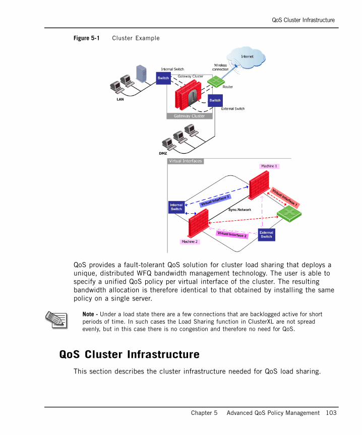
QoS Cluster Infrastructure
Chapter 5 Advanced QoS Policy Management 103
Figure 5-1 Cluster Example
QoS provides a fault-tolerant QoS solution for cluster load sharing that deploys a unique, distributed WFQ bandwidth management technology. The user is able to specify a unified QoS policy per virtual interface of the cluster. The resulting bandwidth allocation is therefore identical to that obtained by installing the same policy on a single server.
QoS Cluster InfrastructureThis section describes the cluster infrastructure needed for QoS load sharing.
Note - Under a load state there are a few connections that are backlogged active for short periods of time. In such cases the Load Sharing function in ClusterXL are not spread evenly, but in this case there is no congestion and therefore no need for QoS.
QoS Cluster Infrastructure
104
Cluster State ClusterXL introduces a member's load value. A member's load, calculated in percentages, is assigned to each member by the cluster. The load is different for ClusterXL multicast and unicast modes. Generally the load for the N members in the cluster equals (100 / N)%. If number of cluster members changes dynamically (due to failover or recovery) the load is dynamically adjusted by the cluster to the appropriate value.
Changes in Cluster StateCluster members are informed of changes in a fellow cluster member’s load. All cluster members, including the causer member recalculate their rates with respect to the new load.
In this way, on the next re-calculation of rates the failed machine’s unutilized bandwidth, will be divided between the active cluster members. This guarantees correct work and the quick recovery of the system when faults have occurred.
Rates Calculation AlgorithmQoS Load Sharing uses a member's load value in order to obtain correct rates allocation for QoS rules.
The rates of the cluster members are calculated in the context of each virtual network interface. These calculations are used for enforcing the scheduling policy of a virtual network interface by setting the local rates of the corresponding real network interface of the cluster members. The cluster member executes this calculation each time ClusterXL informs them of changes in the cluster state.
Basically, in a centralized policy the rate of a rule is divided equally between the matching connections. In load sharing, the set of connections is evenly split between the cluster members by the decision function. Therefore, any rule and sub-rule of a cluster member is assigned a fraction of the original rate that is proportional to the load of member in the cluster. To achieve a guaranteed rate, the limit and allotment of each centralized policy rule are recalculated proportionally to the load of the each member.
Finally, a member's physical interface limit is calculated as a portion of the cluster interface limit, proportional to the member's load.
Note - If for any reason the QoS daemon cannot retrieve a load from the Check Point Load Sharing, it calculates the load statically according to the (100 / N)% formula. Where N is the number of members configured in the cluster topology and which are not necessarily active.
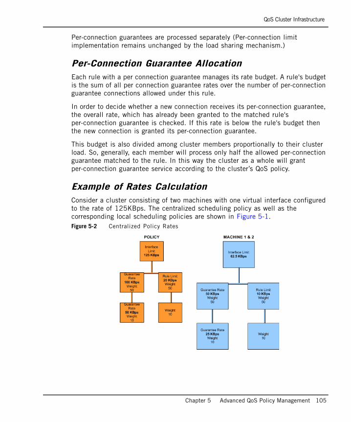
QoS Cluster Infrastructure
Chapter 5 Advanced QoS Policy Management 105
Per-connection guarantees are processed separately (Per-connection limit implementation remains unchanged by the load sharing mechanism.)
Per-Connection Guarantee AllocationEach rule with a per connection guarantee manages its rate budget. A rule's budget is the sum of all per connection guarantee rates over the number of per-connection guarantee connections allowed under this rule.
In order to decide whether a new connection receives its per-connection guarantee, the overall rate, which has already been granted to the matched rule's per-connection guarantee is checked. If this rate is below the rule's budget then the new connection is granted its per-connection guarantee.
This budget is also divided among cluster members proportionally to their cluster load. So, generally, each member will process only half the allowed per-connection guarantee matched to the rule. In this way the cluster as a whole will grant per-connection guarantee service according to the cluster’s QoS policy.
Example of Rates CalculationConsider a cluster consisting of two machines with one virtual interface configured to the rate of 125KBps. The centralized scheduling policy as well as the corresponding local scheduling policies are shown in Figure 5-1.Figure 5-2 Centralized Policy Rates
QoS Cluster Infrastructure
106
ConclusionThe decision function distributes traffic evenly between all cluster members and the resultant load sharing allocates exactly the same rates to the rules/connections as would be done by a centralized policy.
107
Chapter 6Managing QoS
In This Chapter
This chapter describes how to configure and manage QoS. The procedures described in this chapter all presuppose that you have already started the SmartDashboard application as described on page 54.
Defining QoS Global Properties page 108
Specifying Interface QoS Properties page 110
Editing QoS Rule Bases page 114
Modifying Rules page 119
Defining Sub-Rules page 138
Working with Differentiated Services (DiffServ) page 140
Working with Low Latency Classes page 146
Working with Authenticated QoS page 149
Managing QoS for Citrix ICA Applications page 151
Managing QoS for Citrix Printing page 157
Viewing QoS Gateway Status page 159
Enabling Log Collection page 160
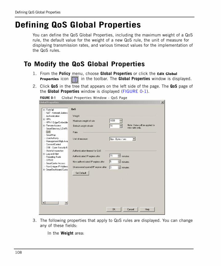
Defining QoS Global Properties
108
Defining QoS Global PropertiesYou can define the QoS Global Properties, including the maximum weight of a QoS rule, the default value for the weight of a new QoS rule, the unit of measure for displaying transmission rates, and various timeout values for the implementation of the QoS rules.
To Modify the QoS Global Properties1. From the Policy menu, choose Global Properties or click the Edit Global
Properties icon in the toolbar. The Global Properties window is displayed.
2. Click QoS in the tree that appears on the left side of the page. The QoS page of the Global Properties window is displayed (FIGURE 0-1).FIGURE 0-1 Global Properties Window - QoS Page
3. The following properties that apply to QoS rules are displayed. You can change any of these fields:
In the Weight area:
To Modify the QoS Global Properties
Chapter 6 Managing QoS 109
• Maximum weight of rule: The maximum weight that can be assigned to rules. The default value is 1000, but can be changed to any number.
• Default weight of rule: The weight to be assigned in the Action column by default to new rules, including new Default rules.
In the Rate area:
• Unit of measure: The unit specified in QoS windows by default for transmission rates (for example, Bps - Bytes per second).
In the Authenticated timeout for QoS area:
• Authenticated IP expires after: If a user has been authenticated, all connections that are opened within the specified time receive the guaranteed bandwidth connection. Any connection opened after the specified time will be queried with the User Authority Server (UAS) again.
• Non authenticated IP expires after: If a user has previously tried and failed to be authenticated by the QoS Policy, then all connections that are opened within the specified time will not receive the guaranteed bandwidth connection. This means that they will not match that specific rule during that time.
• Unresponded queried IP expires after: The User Authority Server (UAS) database is queried to see if a user’s IP has been previously authenticated using Client Authentication or SSL. Until an answer is received, connections from this user will be classified to the next matching rule. If an answer is not received within the specified time, there will be another query.
4. Click OK to save the changes to the QoS Global Properties.
Note - Click Set Default to restore the default settings for the Authentication timeout for QoS parameters.
Specifying Interface QoS Properties
110
Specifying Interface QoS PropertiesYou must first define the network objects, that is, the gateway and its interfaces on which QoS controls traffic flow. For further information, see Network Objects in SmartCenter Administration Guide.
After defining the interfaces you can specify the QoS properties for those interfaces. This is done in the QoS tab of the Interface Properties window. Defining the interface QoS properties involves setting the Inbound and Outbound active transmission rates and specifying the Differentiated Services (DiffServ) and Low Latency classes. You can change these definitions at any time.
To Define the Interface QoS Properties1. Open the Properties window for the appropriate gateway by double-clicking the
gateway in the Objects Tree, or by choosing the gateway from the list in the Network Objects window. The Check Point Gateway - General Properties window is displayed (FIGURE 0-2).
Note - The QoS tab is only enabled for the interfaces of gateways that have QoS checked under Check Point Products in the General Properties of the Check Point Gateway window, as shown in FIGURE 0-2 on page 111.
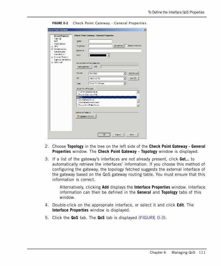
To Define the Interface QoS Properties
Chapter 6 Managing QoS 111
FIGURE 0-2 Check Point Gateway - General Properties
2. Choose Topology in the tree on the left side of the Check Point Gateway - General Properties window. The Check Point Gateway - Topology window is displayed.
3. If a list of the gateway’s interfaces are not already present, click Get... to automatically retrieve the interfaces’ information. If you choose this method of configuring the gateway, the topology fetched suggests the external interface of the gateway based on the QoS gateway routing table. You must ensure that this information is correct.
Alternatively, clicking Add displays the Interface Properties window. Interface information can then be defined in the General and Topology tabs of this window.
4. Double-click on the appropriate interface, or select it and click Edit. The Interface Properties window is displayed.
5. Click the QoS tab. The QoS tab is displayed (FIGURE 0-3).
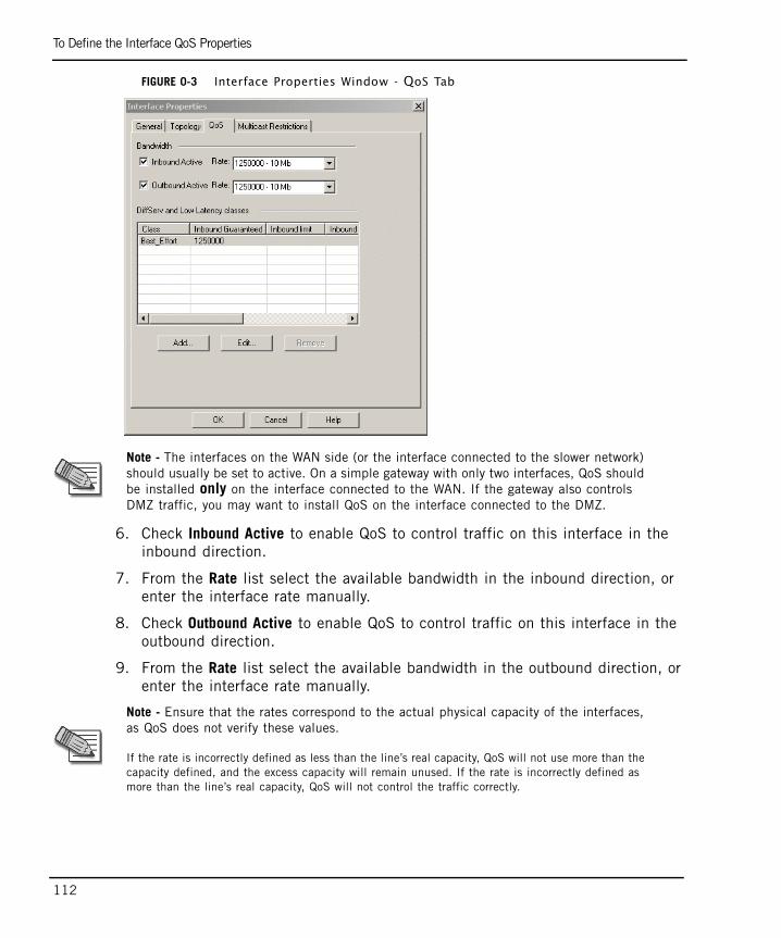
To Define the Interface QoS Properties
112
FIGURE 0-3 Interface Properties Window - QoS Tab
6. Check Inbound Active to enable QoS to control traffic on this interface in the inbound direction.
7. From the Rate list select the available bandwidth in the inbound direction, or enter the interface rate manually.
8. Check Outbound Active to enable QoS to control traffic on this interface in the outbound direction.
9. From the Rate list select the available bandwidth in the outbound direction, or enter the interface rate manually.
Note - The interfaces on the WAN side (or the interface connected to the slower network) should usually be set to active. On a simple gateway with only two interfaces, QoS should be installed only on the interface connected to the WAN. If the gateway also controls DMZ traffic, you may want to install QoS on the interface connected to the DMZ.
Note - Ensure that the rates correspond to the actual physical capacity of the interfaces, as QoS does not verify these values.
If the rate is incorrectly defined as less than the line’s real capacity, QoS will not use more than the capacity defined, and the excess capacity will remain unused. If the rate is incorrectly defined as more than the line’s real capacity, QoS will not control the traffic correctly.
To Define the Interface QoS Properties
Chapter 6 Managing QoS 113
10. In the DiffServ and Low Latency classes area, you can specify the Differentiated Services (DiffServ) and Low Latency Queuing classes to be used on the interface.
You can Add, Edit or Remove a class. Refer to “Working with Differentiated Services (DiffServ)” on page 140 and “Working with Low Latency Classes” on page 146 for more details on adding or editing DiffServ and Low Latency Classes.
For information about DiffServ and Low Latency classes, see “Differentiated Services (DiffServ)” on page 89 and “Low Latency Queuing” on page 91.
11. Click OK to save the changes to the interface QoS properties.
12. Repeat from step 4. above for each of the relevant interfaces.
Editing QoS Rule Bases
114
Editing QoS Rule BasesA Policy Package comprises several Rule Bases, depending on the policy types selected.
Qos policy is implemented by defining an ordered set of rules in the Rule Base. The Rule Base is comprised of those rules which you create and a default rule. The default rule is automatically created with the Rule Base. It can be modified but cannot be deleted. The fundamental concept of the Rule Base is that unless other rules apply, the default rule is applied to all data packets. The default rule is therefore always the last rule in the Rule Base.
The Rule Base specifies what actions are to be taken with the data packets. It specifies the source and destination of the communication, what services can be used, at what times, whether to log the connection and the logging level.
A QoS Rule Base is applied to specific gateways and interfaces. After you have created the Policy Package and defined its QoS rules you must install it on the relevant QoS gateways.
For further details, refer to “Overview” on page 40.
In This Section
To Create a New Policy Package1. From the File menu choose New. The New Policy Package window is displayed.
2. Enter the name of the Policy Package in the New Policy Package Name field. This name cannot:
• Contain any reserved words or spaces.
• Start with a number.
• Contain any of the following characters:%, #, ‘, &, *,!, @, ?, <, >, /, \, :.
To Create a New Policy Package page 114
To Open an Existing Policy Package page 115
To Add a Rule Base page 115
To Rename a Rule page 117
To Copy, Cut or Paste a Rule page 117
To Delete a Rule page 118
To Open an Existing Policy Package
Chapter 6 Managing QoS 115
• End with any of the following suffixes: .w, .pf, .W.
3. In the QoS area, select whether you want Traditional mode or Express mode. See “Interaction with VPN-1” on page 37
4. Click OK to save the Policy Package to a new file. The new Policy Package is saved and a Default Rule is automatically created.
To Open an Existing Policy Package1. From the File menu choose Open. The Open Policy Package window is displayed.
2. Double-click on the appropriate Policy Package, or select it and click Open. The selected Policy Package is displayed.
To Add a Rule BaseWhen you add rules to a Policy Package you can position the new rule at any location in the Policy Package. The Default Rule which is automatically created with the Rule Base must always remain in the last position in the Rule Base.
1. Position your mouse cursor in the Name field of the QoS tab, at the position where you want to add a new rule.
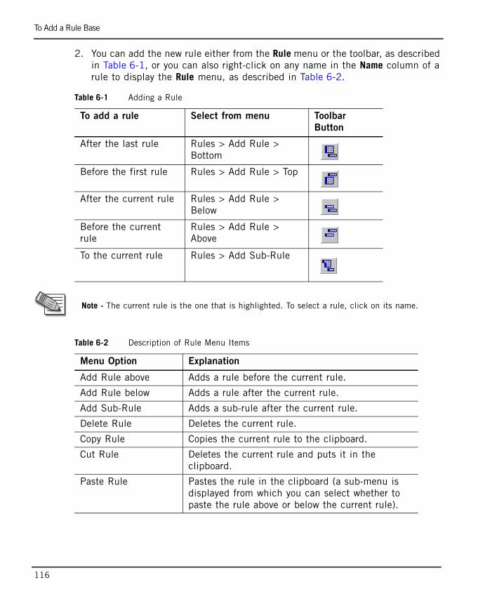
To Add a Rule Base
116
2. You can add the new rule either from the Rule menu or the toolbar, as described in Table 6-1, or you can also right-click on any name in the Name column of a rule to display the Rule menu, as described in Table 6-2.
Table 6-1 Adding a Rule
To add a rule Select from menu Toolbar
Button
After the last rule Rules > Add Rule > Bottom
Before the first rule Rules > Add Rule > Top
After the current rule Rules > Add Rule > Below
Before the current rule
Rules > Add Rule > Above
To the current rule Rules > Add Sub-Rule
Note - The current rule is the one that is highlighted. To select a rule, click on its name.
Table 6-2 Description of Rule Menu Items
Menu Option Explanation
Add Rule above Adds a rule before the current rule.
Add Rule below Adds a rule after the current rule.
Add Sub-Rule Adds a sub-rule after the current rule.
Delete Rule Deletes the current rule.
Copy Rule Copies the current rule to the clipboard.
Cut Rule Deletes the current rule and puts it in the clipboard.
Paste Rule Pastes the rule in the clipboard (a sub-menu is displayed from which you can select whether to paste the rule above or below the current rule).
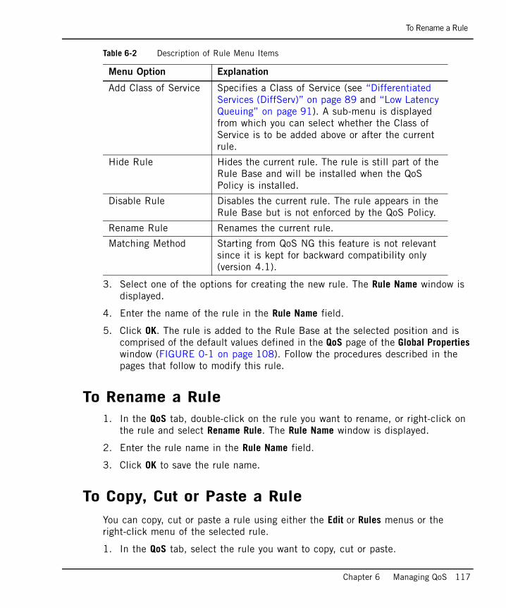
To Rename a Rule
Chapter 6 Managing QoS 117
3. Select one of the options for creating the new rule. The Rule Name window is displayed.
4. Enter the name of the rule in the Rule Name field.
5. Click OK. The rule is added to the Rule Base at the selected position and is comprised of the default values defined in the QoS page of the Global Properties window (FIGURE 0-1 on page 108). Follow the procedures described in the pages that follow to modify this rule.
To Rename a Rule1. In the QoS tab, double-click on the rule you want to rename, or right-click on
the rule and select Rename Rule. The Rule Name window is displayed.
2. Enter the rule name in the Rule Name field.
3. Click OK to save the rule name.
To Copy, Cut or Paste a RuleYou can copy, cut or paste a rule using either the Edit or Rules menus or the right-click menu of the selected rule.
1. In the QoS tab, select the rule you want to copy, cut or paste.
Add Class of Service Specifies a Class of Service (see “Differentiated Services (DiffServ)” on page 89 and “Low Latency Queuing” on page 91). A sub-menu is displayed from which you can select whether the Class of Service is to be added above or after the current rule.
Hide Rule Hides the current rule. The rule is still part of the Rule Base and will be installed when the QoS Policy is installed.
Disable Rule Disables the current rule. The rule appears in the Rule Base but is not enforced by the QoS Policy.
Rename Rule Renames the current rule.
Matching Method Starting from QoS NG this feature is not relevant since it is kept for backward compatibility only (version 4.1).
Table 6-2 Description of Rule Menu Items
Menu Option Explanation
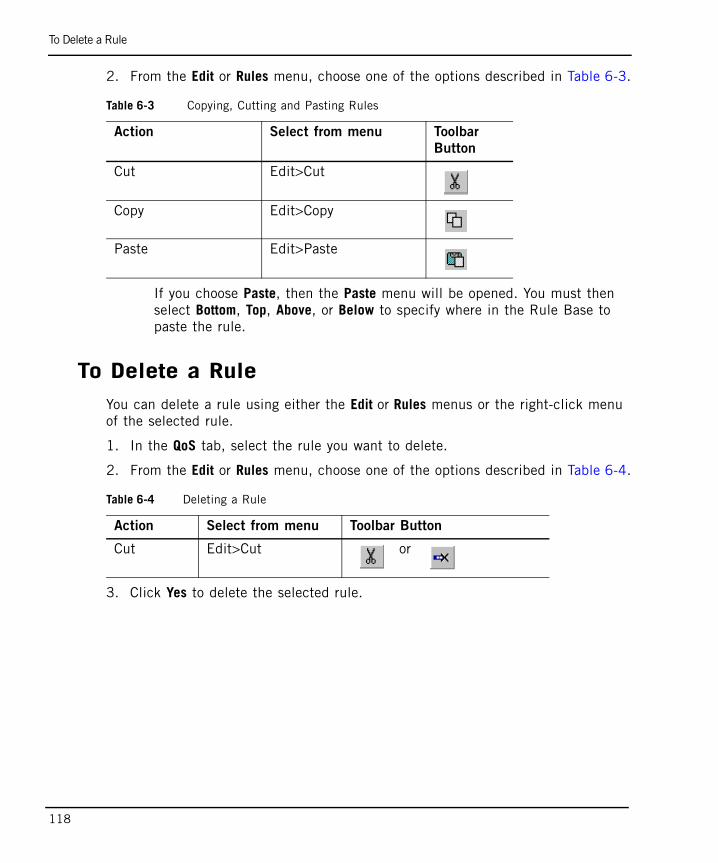
To Delete a Rule
118
2. From the Edit or Rules menu, choose one of the options described in Table 6-3.
If you choose Paste, then the Paste menu will be opened. You must then select Bottom, Top, Above, or Below to specify where in the Rule Base to paste the rule.
To Delete a RuleYou can delete a rule using either the Edit or Rules menus or the right-click menu of the selected rule.
1. In the QoS tab, select the rule you want to delete.
2. From the Edit or Rules menu, choose one of the options described in Table 6-4.
3. Click Yes to delete the selected rule.
Table 6-3 Copying, Cutting and Pasting Rules
Action Select from menu Toolbar
Button
Cut Edit>Cut
Copy Edit>Copy
Paste Edit>Paste
Table 6-4 Deleting a Rule
Action Select from menu Toolbar Button
Cut Edit>Cut or
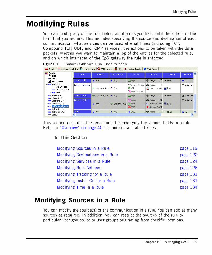
Modifying Rules
Chapter 6 Managing QoS 119
Modifying RulesYou can modify any of the rule fields, as often as you like, until the rule is in the form that you require. This includes specifying the source and destination of each communication, what services can be used at what times (including TCP, Compound TCP, UDP, and ICMP services), the actions to be taken with the data packets, whether you want to maintain a log of the entries for the selected rule, and on which interfaces of the QoS gateway the rule is enforced.Figure 6-1 SmartDashboard Rule Base Window
This section describes the procedures for modifying the various fields in a rule. Refer to “Overview” on page 40 for more details about rules.
In This Section
Modifying Sources in a RuleYou can modify the source(s) of the communication in a rule. You can add as many sources as required. In addition, you can restrict the sources of the rule to particular user groups, or to user groups originating from specific locations.
Modifying Sources in a Rule page 119
Modifying Destinations in a Rule page 122
Modifying Services in a Rule page 124
Modifying Rule Actions page 126
Modifying Tracking for a Rule page 131
Modifying Install On for a Rule page 131
Modifying Time in a Rule page 134
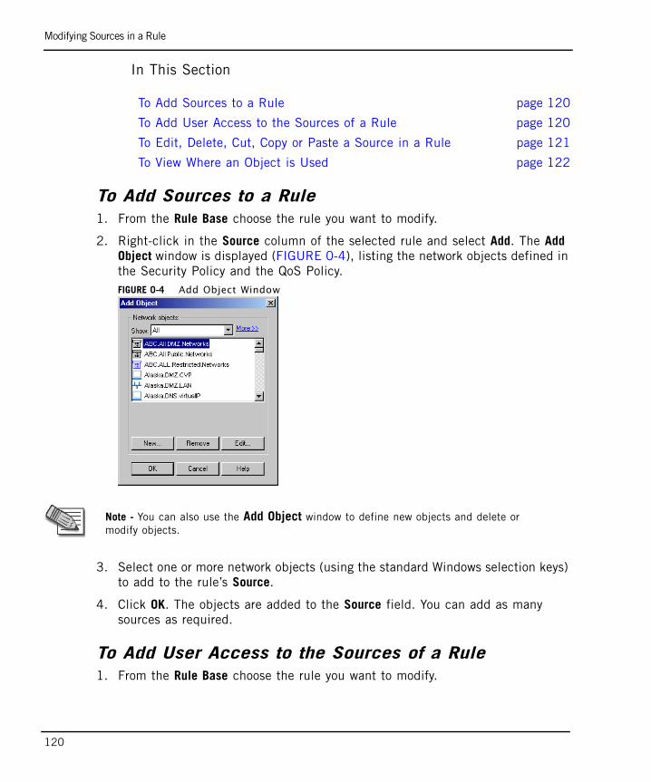
Modifying Sources in a Rule
120
In This Section
To Add Sources to a Rule1. From the Rule Base choose the rule you want to modify.
2. Right-click in the Source column of the selected rule and select Add. The Add Object window is displayed (FIGURE 0-4), listing the network objects defined in the Security Policy and the QoS Policy.FIGURE 0-4 Add Object Window
3. Select one or more network objects (using the standard Windows selection keys) to add to the rule’s Source.
4. Click OK. The objects are added to the Source field. You can add as many sources as required.
To Add User Access to the Sources of a Rule1. From the Rule Base choose the rule you want to modify.
To Add Sources to a Rule page 120
To Add User Access to the Sources of a Rule page 120
To Edit, Delete, Cut, Copy or Paste a Source in a Rule page 121
To View Where an Object is Used page 122
Note - You can also use the Add Object window to define new objects and delete or modify objects.
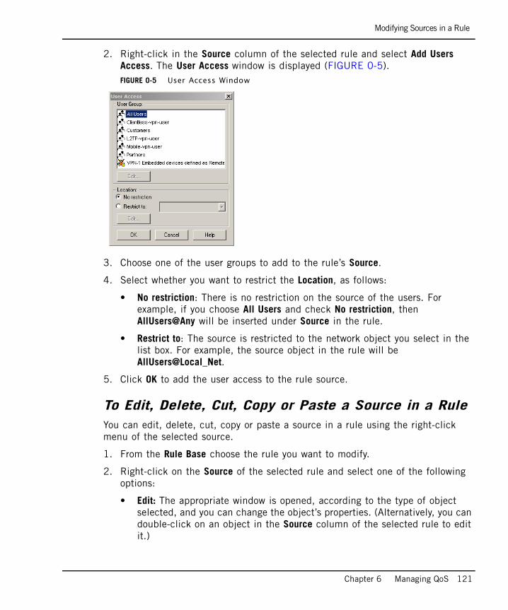
Modifying Sources in a Rule
Chapter 6 Managing QoS 121
2. Right-click in the Source column of the selected rule and select Add Users Access. The User Access window is displayed (FIGURE 0-5).FIGURE 0-5 User Access Window
3. Choose one of the user groups to add to the rule’s Source.
4. Select whether you want to restrict the Location, as follows:
• No restriction: There is no restriction on the source of the users. For example, if you choose All Users and check No restriction, then AllUsers@Any will be inserted under Source in the rule.
• Restrict to: The source is restricted to the network object you select in the list box. For example, the source object in the rule will be AllUsers@Local_Net.
5. Click OK to add the user access to the rule source.
To Edit, Delete, Cut, Copy or Paste a Source in a RuleYou can edit, delete, cut, copy or paste a source in a rule using the right-click menu of the selected source.
1. From the Rule Base choose the rule you want to modify.
2. Right-click on the Source of the selected rule and select one of the following options:
• Edit: The appropriate window is opened, according to the type of object selected, and you can change the object’s properties. (Alternatively, you can double-click on an object in the Source column of the selected rule to edit it.)
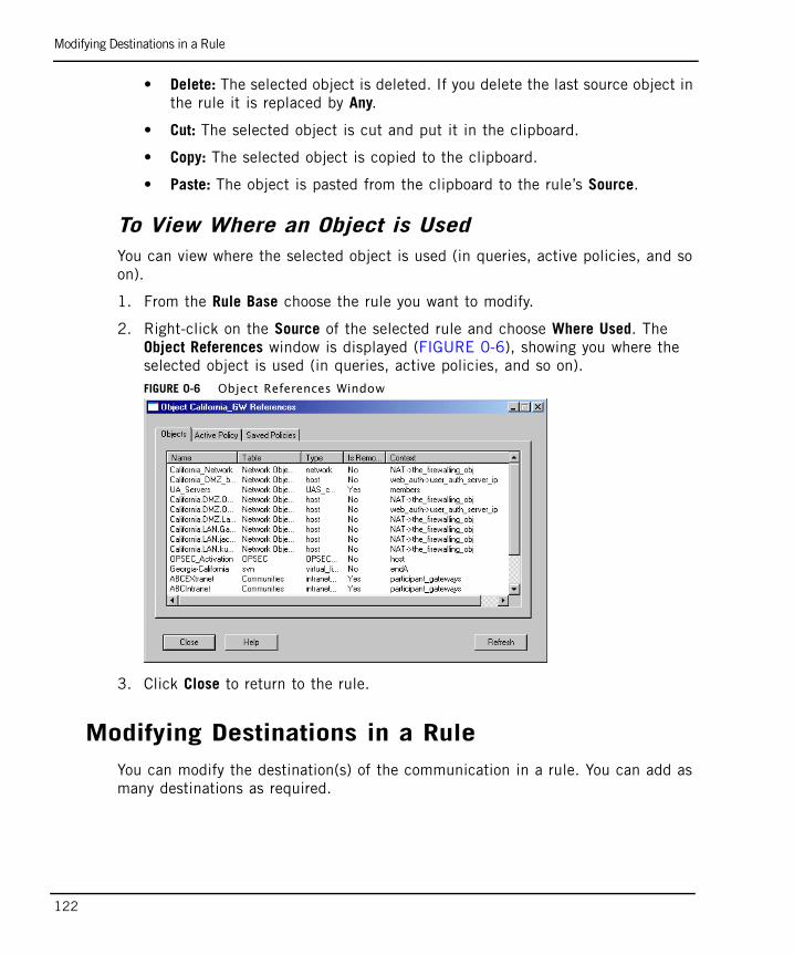
Modifying Destinations in a Rule
122
• Delete: The selected object is deleted. If you delete the last source object in the rule it is replaced by Any.
• Cut: The selected object is cut and put it in the clipboard.
• Copy: The selected object is copied to the clipboard.
• Paste: The object is pasted from the clipboard to the rule’s Source.
To View Where an Object is UsedYou can view where the selected object is used (in queries, active policies, and so on).
1. From the Rule Base choose the rule you want to modify.
2. Right-click on the Source of the selected rule and choose Where Used. The Object References window is displayed (FIGURE 0-6), showing you where the selected object is used (in queries, active policies, and so on).FIGURE 0-6 Object References Window
3. Click Close to return to the rule.
Modifying Destinations in a RuleYou can modify the destination(s) of the communication in a rule. You can add as many destinations as required.
Modifying Destinations in a Rule
Chapter 6 Managing QoS 123
In This Section
To Add Destinations to a Rule1. From the Rule Base choose the rule you want to modify.
2. Right-click in the Destination column of the selected rule and select Add. The Add Object window is displayed (FIGURE 0-4), listing the network objects defined in the Security Policy and the QoS Policy.
3. Select one or more network objects (using the standard Windows selection keys) to add to the rule’s Destination.
4. Click OK. The objects are added to the Destination field. You can add as many destinations as required.
To Edit, Delete, Cut, Copy or Paste a Destination in a RuleYou can edit, delete, cut, copy or paste a destination in a rule using the right-click menu of the selected source.
1. From the Rule Base choose the rule you want to modify.
2. Right-click on the Destination of the selected rule and select one of the following options:
• Edit: The appropriate window is opened, according to the type of object selected, and you can change the object’s properties. (Alternatively, you can double-click on an object in the Destination column of the selected rule to edit it.)
• Delete: The selected object is deleted. If you delete the last destination object in the rule it is replaced by Any.
• Cut: The selected object is cut and put it in the clipboard.
• Copy: The selected object is copied to the clipboard.
To Add Destinations to a Rule page 123
To Edit, Delete, Cut, Copy or Paste a Destination in a Rule page 123
To View Where an Object is Used page 126
Note - You can also use the Add Object window to define new objects and delete or modify objects.
Modifying Services in a Rule
124
• Paste: The object is pasted from the clipboard to the rule’s Destination.
To View Where an Object is UsedYou can view where the selected object is used (in queries, active policies, and so on).
1. From the Rule Base choose the rule you want to modify.
2. Right-click on the Source of the selected rule and choose Where Used. The Object References window is displayed (FIGURE 0-6), showing you where the selected object is used (in queries, active policies, and so on).
3. Click Close to return to the rule.
Modifying Services in a RuleYou can modify the service(s) in a rule. You can add as many services as required, however, you can only add one URI for QoS resource in a single rule.
In This Section
To Add Services to a Rule1. From the Rule Base choose the rule you want to modify.
2. Right-click in the Service column of the selected rule and select Add. The Add Object window is displayed (FIGURE 0-4), listing the network objects defined in the Security Policy and the QoS Policy.
3. Select one or more network objects (using the standard Windows selection keys) to add to the rule’s Service.
4. Click OK. The objects are added to the Service field. You can add as many services as required. However only one TCP Citrix or URI for QoS service is allowed.
Note - Previous versions of QoS have not limited the number of URIs for QoS resources allowed per rule. If you are using a QoS Policy originally designed for use with a previous QoS version, be sure to redefine any rule that has more than one resource in its Service Field.
To Add Services to a Rule page 124
To Add a Service with a Resource to a Rule page 125
To Edit, Delete, Cut, Copy or Paste a Service in a Rule page 125
To View Where an Object is Used page 126
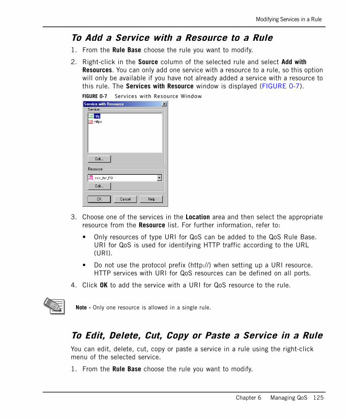
Modifying Services in a Rule
Chapter 6 Managing QoS 125
To Add a Service with a Resource to a Rule1. From the Rule Base choose the rule you want to modify.
2. Right-click in the Source column of the selected rule and select Add with Resources. You can only add one service with a resource to a rule, so this option will only be available if you have not already added a service with a resource to this rule. The Services with Resource window is displayed (FIGURE 0-7). FIGURE 0-7 Services with Resource Window
3. Choose one of the services in the Location area and then select the appropriate resource from the Resource list. For further information, refer to:
• Only resources of type URI for QoS can be added to the QoS Rule Base. URI for QoS is used for identifying HTTP traffic according to the URL (URI).
• Do not use the protocol prefix (http://) when setting up a URI resource. HTTP services with URI for QoS resources can be defined on all ports.
4. Click OK to add the service with a URI for QoS resource to the rule.
To Edit, Delete, Cut, Copy or Paste a Service in a RuleYou can edit, delete, cut, copy or paste a service in a rule using the right-click menu of the selected service.
1. From the Rule Base choose the rule you want to modify.
Note - Only one resource is allowed in a single rule.
Modifying Rule Actions
126
2. Right-click on the Service of the selected rule and select one of the following options:
• Edit: The appropriate window is opened, according to the type of object selected, and you can change the object’s properties. (Alternatively, you can double-click on an object in the Service column of the selected rule to edit it.)
• Delete: The selected object is deleted. If you delete the last service object in the rule it is replaced by Any.
• Cut: The selected object is cut and put it in the clipboard.
• Copy: The selected object is copied to the clipboard.
• Paste: The object is pasted from the clipboard to the rule’s Service.
To View Where an Object is UsedYou can view where the selected object is used (in queries, active policies, and so on).
1. From the Rule Base choose the rule you want to modify.
2. Right-click on the Service of the selected rule and choose Where Used. The Object References window is displayed (FIGURE 0-6), showing you where the selected object is used (in queries, active policies, and so on).
3. Click Close to return to the rule.
Modifying Rule ActionsYou can modify the default properties of a rule. The options available vary according to the action type of rule, that is whether the rule is defined as simple or advanced. The advanced rule action type enables you to specify limits and guarantee allocation on a per connection basis.
In This Section
To Edit the Rule Actions1. From the Rule Base choose the rule you want to modify.
To Edit the Rule Actions page 126
To Reset the Rule Actions to Default Values page 130
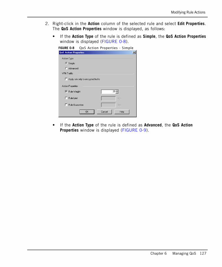
Modifying Rule Actions
Chapter 6 Managing QoS 127
2. Right-click in the Action column of the selected rule and select Edit Properties. The QoS Action Properties window is displayed, as follows:
• If the Action Type of the rule is defined as Simple, the QoS Action Properties window is displayed (FIGURE 0-8).
FIGURE 0-8 QoS Action Properties - Simple
• If the Action Type of the rule is defined as Advanced, the QoS Action Properties window is displayed (FIGURE 0-9).
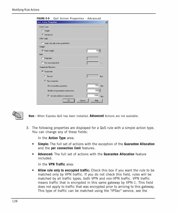
Modifying Rule Actions
128
FIGURE 0-9 QoS Action Properties - Advanced
3. The following properties are displayed for a QoS rule with a simple action type. You can change any of these fields:
In the Action Type area:
• Simple: The full set of actions with the exception of the Guarantee Allocation and the per connection limit features.
• Advanced: The full set of actions with the Guarantee Allocation feature included.
In the VPN Traffic area:
• Allow rule only to encrypted traffic: Check this box if you want the rule to be matched only by VPN traffic. If you do not check this field, rules will be matched by all traffic types, both VPN and non-VPN traffic. VPN traffic means traffic that is encrypted in this same gateway by VPN-1. This field does not apply to traffic that was encrypted prior to arriving to this gateway. This type of traffic can be matched using the "IPSec" service, see the
Note - When Express QoS has been installed, Advanced Actions are not available.
Modifying Rule Actions
Chapter 6 Managing QoS 129
SmartCenter Administration Guide. For further explanation on how to use this check box for prioritizing VPN traffic over non-VPN, see “Example of a Rule Matching VPN Traffic” on page 46.
In the Action Properties area you can define the restrictions on bandwidth for connections to which the rule applies in the following fields:
• Rule Weight: Enables you to define the weight of the rule. This field is checked by default and has the value defined in the Global Properties window in “Defining QoS Global Properties” on page 108. It is recommended to leave this value as is to avoid a complete loss of bandwidth. For detailed information see “Weight” on page 43.
• Rule Limit: Enables you to restrict the total bandwidth consumed by the rule. For detailed information see “Limits” on page 44.
• Rule Guarantee: Enables you to define the absolute bandwidth allocated to the rule. For detailed information see “Guarantees” on page 44.
4. (Optional) The following additional properties are displayed for a QoS rule with an advanced action type. You can change any of these fields:
In the Limit area:
• Rule Limit: Enables you to restrict the total bandwidth consumed by the rule. For detailed information see “Limits” on page 44.
Warning - 0 rate in conjunction with 0 guarantee can lead to the rule’s complete loss of bandwidth. To prevent this from happening, retain some ratio in the Rule Weight. The default is 10.
Tip - When using weights or guarantees, the weighted fair queuing algorithm that QoS makes use of assures that no bandwidth is ever wasted. Spare bandwidth is divided among the backlogged rules. However, if you set a rule limit, it will not use spare bandwidth above this limit.
Note - The number you enter for the Rule Guarantee cannot be larger than the Rule Limit.
Tip - When using weights or guarantees, the weighted fair queuing algorithm that QoS makes use of assures that no bandwidth is ever wasted. Spare bandwidth is divided among the backlogged rules. However, if you set a rule limit, it will not use spare bandwidth above this limit.
Modifying Rule Actions
130
• Per connection limit: Enables you to set a rule limit per connection.
In the Guarantee Allocation area:
• Guarantee: Enables you to allocate a minimum bandwidth to the connections matched with a rule. For detailed information see “Guarantees” on page 44.
• Per rule: Enables you to define the absolute bandwidth allocated to the rule.
• Per connection: Enables you to manage the bandwidth at the connection-level.
• Per connection guarantee: Enables you to restrict the absolute bandwidth allocated per connection.
• Number of guaranteed connections: Enables you to allocate a minimum number of guaranteed connections
• Accept additional connections: Check this checkbox to allow connections without per connection guarantees to pass through this rule and receive any left over bandwidth. Enter the maximum amount of bandwidth that is allowed for this option in the text box. This only occurs if all other conditions have been met.
5. Click OK to update the QoS Action Properties for the rule.
To Reset the Rule Actions to Default Values1. From the Rule Base choose the rule you want to modify.
Note - The number you enter for the Rule Guarantee cannot be larger than the Rule Limit.
Note - The number you enter for the Per rule cannot be larger than the Rule Limit.
Note - The Number of guaranteed connections multiplied by the Per connection guarantee cannot be greater than the rule limit.
Note - Select a non-zero rule weight when Accept additional non-guaranteed connections is checked.
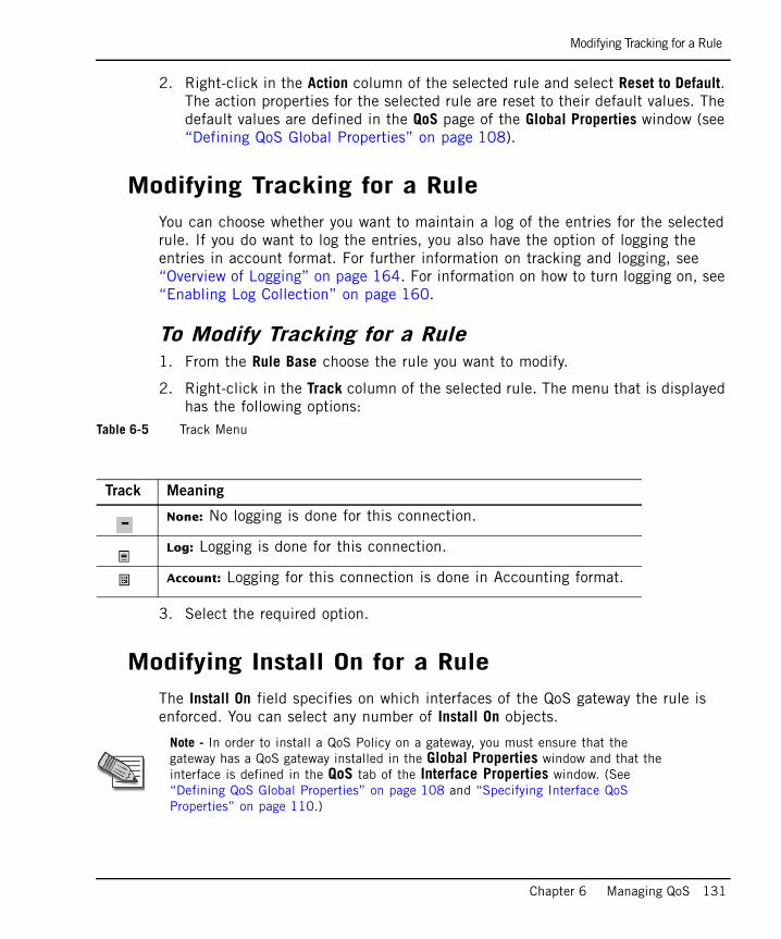
Modifying Tracking for a Rule
Chapter 6 Managing QoS 131
2. Right-click in the Action column of the selected rule and select Reset to Default. The action properties for the selected rule are reset to their default values. The default values are defined in the QoS page of the Global Properties window (see “Defining QoS Global Properties” on page 108).
Modifying Tracking for a RuleYou can choose whether you want to maintain a log of the entries for the selected rule. If you do want to log the entries, you also have the option of logging the entries in account format. For further information on tracking and logging, see “Overview of Logging” on page 164. For information on how to turn logging on, see “Enabling Log Collection” on page 160.
To Modify Tracking for a Rule1. From the Rule Base choose the rule you want to modify.
2. Right-click in the Track column of the selected rule. The menu that is displayed has the following options:
Table 6-5 Track Menu
3. Select the required option.
Modifying Install On for a RuleThe Install On field specifies on which interfaces of the QoS gateway the rule is enforced. You can select any number of Install On objects.
Track Meaning
None: No logging is done for this connection.
Log: Logging is done for this connection.
Account: Logging for this connection is done in Accounting format.
Note - In order to install a QoS Policy on a gateway, you must ensure that the gateway has a QoS gateway installed in the Global Properties window and that the interface is defined in the QoS tab of the Interface Properties window. (See “Defining QoS Global Properties” on page 108 and “Specifying Interface QoS Properties” on page 110.)
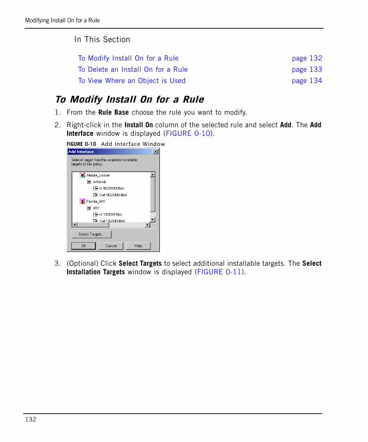
Modifying Install On for a Rule
132
In This Section
To Modify Install On for a Rule1. From the Rule Base choose the rule you want to modify.
2. Right-click in the Install On column of the selected rule and select Add. The Add Interface window is displayed (FIGURE 0-10).FIGURE 0-10 Add Interface Window
3. (Optional) Click Select Targets to select additional installable targets. The Select Installation Targets window is displayed (FIGURE 0-11).
To Modify Install On for a Rule page 132
To Delete an Install On for a Rule page 133
To View Where an Object is Used page 134
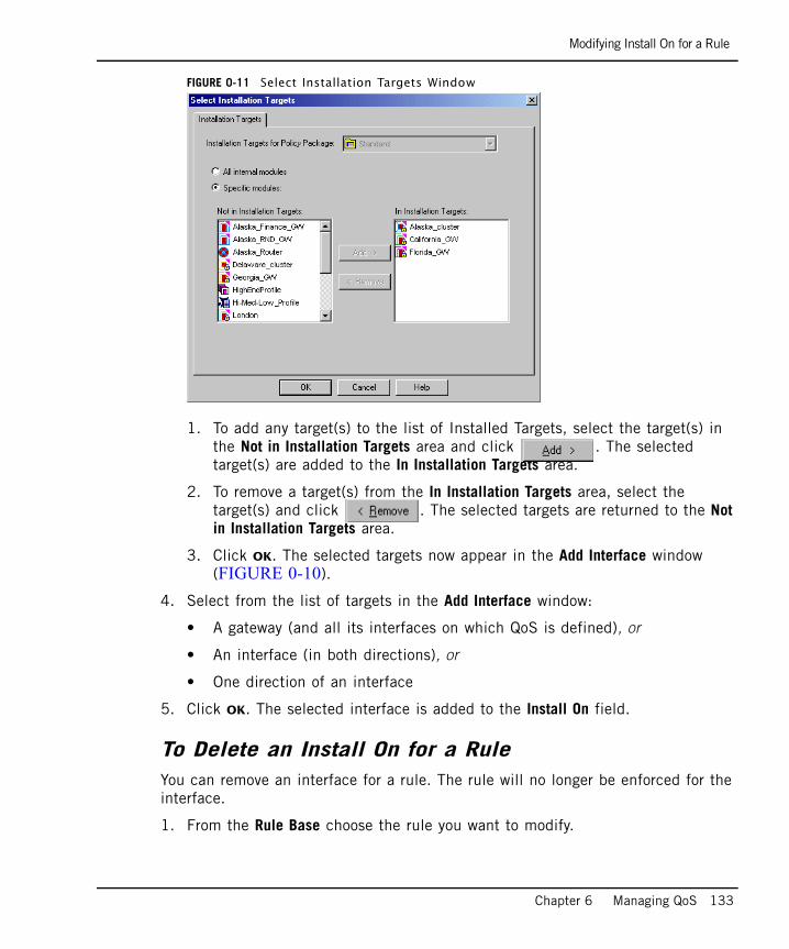
Modifying Install On for a Rule
Chapter 6 Managing QoS 133
FIGURE 0-11 Select Installation Targets Window
1. To add any target(s) to the list of Installed Targets, select the target(s) in the Not in Installation Targets area and click . The selected target(s) are added to the In Installation Targets area.
2. To remove a target(s) from the In Installation Targets area, select the target(s) and click . The selected targets are returned to the Not in Installation Targets area.
3. Click OK. The selected targets now appear in the Add Interface window (FIGURE 0-10).
4. Select from the list of targets in the Add Interface window:
• A gateway (and all its interfaces on which QoS is defined), or
• An interface (in both directions), or
• One direction of an interface
5. Click OK. The selected interface is added to the Install On field.
To Delete an Install On for a RuleYou can remove an interface for a rule. The rule will no longer be enforced for the interface.
1. From the Rule Base choose the rule you want to modify.
Modifying Time in a Rule
134
2. Right-click on the Service of the selected rule and select Delete. The selected object is deleted.
To View Where an Object is UsedYou can view where the selected object is used.
1. From the Rule Base choose the rule you want to modify.
2. Right-click on the Install On of the selected rule and choose Where Used. The Object References window is displayed (FIGURE 0-6), showing you where the selected object is used.
3. Click Close to return to the rule.
Modifying Time in a RuleYou can specify the times that the rule is enforced. You add any number of time objects to a rule.
In This Section
To Modify Time in Rules1. From the Rule Base choose the rule you want to modify.
2. Right-click in the Time column of the selected rule and select Add. The Add Object window is displayed (FIGURE 0-12).
To Modify Time in Rules page 134
To Edit or Delete a Time Object for a Rule page 136
To View Where an Object is Used page 136
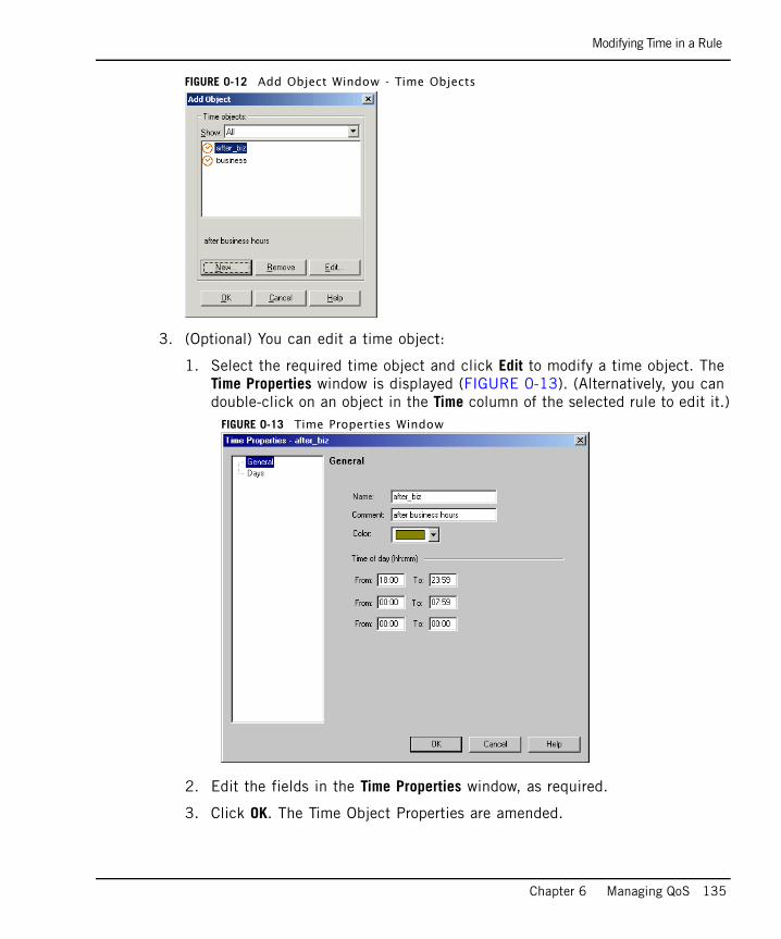
Modifying Time in a Rule
Chapter 6 Managing QoS 135
FIGURE 0-12 Add Object Window - Time Objects
3. (Optional) You can edit a time object:
1. Select the required time object and click Edit to modify a time object. The Time Properties window is displayed (FIGURE 0-13). (Alternatively, you can double-click on an object in the Time column of the selected rule to edit it.)
FIGURE 0-13 Time Properties Window
2. Edit the fields in the Time Properties window, as required.
3. Click OK. The Time Object Properties are amended.
Adding Comments to a Rule
136
4. Select the required time object in the Add Object window. The time object is added to the rule.
To Edit or Delete a Time Object for a RuleYou can edit or delete a time object in a rule using the right-click menu of the selected service.
1. From the Rule Base choose the rule you want to modify.
2. Right-click on the Time of the selected rule and select one of the following options:
• Edit: The appropriate window is opened, according to the type of object selected, and you can change the object’s properties. (Alternatively, you can double-click on an object in the Time column of the selected rule to edit it.)
• Delete: The selected object is deleted. If you delete the last time object in the rule it is replaced by Any.
To View Where an Object is UsedYou can view where the selected object is used (in queries, active policies, and so on).
1. From the Rule Base choose the rule you want to modify.
2. Right-click on the Service of the selected rule and choose Where Used. The Object References window is displayed (FIGURE 0-6), showing you where the selected object is used (in queries, active policies, and so on).
3. Click Close to return to the rule.
Adding Comments to a RuleYou can add a comment to a rule.
To Add Comments to Rules1. From the Rule Base choose the rule you want to modify.
2. Right-click in the Comment column of the selected rule and select Edit. The Comment window is displayed (FIGURE 0-14). You can also open this window by double-clicking in the Comment column of the selected rule.
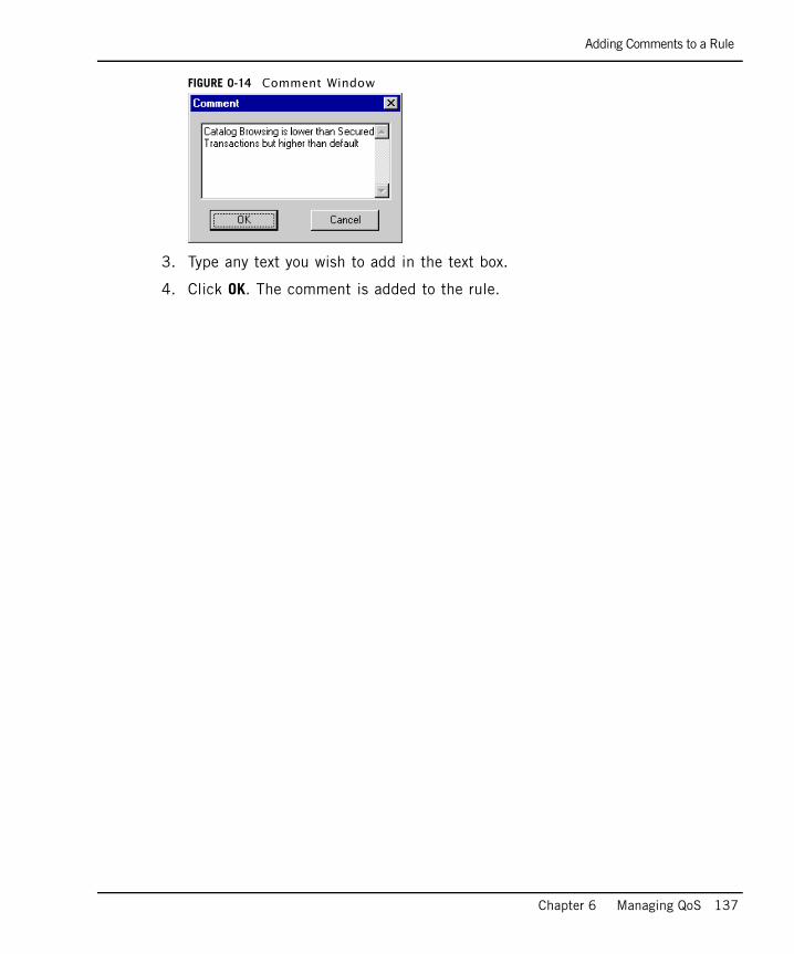
Adding Comments to a Rule
Chapter 6 Managing QoS 137
FIGURE 0-14 Comment Window
3. Type any text you wish to add in the text box.
4. Click OK. The comment is added to the rule.
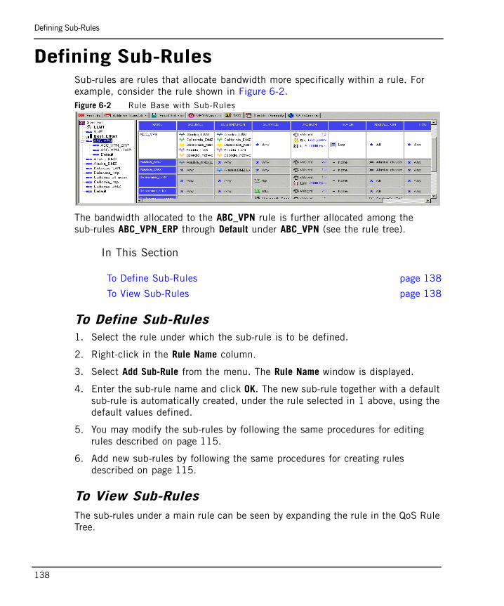
Defining Sub-Rules
138
Defining Sub-RulesSub-rules are rules that allocate bandwidth more specifically within a rule. For example, consider the rule shown in Figure 6-2.Figure 6-2 Rule Base with Sub-Rules
The bandwidth allocated to the ABC_VPN rule is further allocated among the sub-rules ABC_VPN_ERP through Default under ABC_VPN (see the rule tree).
In This Section
To Define Sub-Rules1. Select the rule under which the sub-rule is to be defined.
2. Right-click in the Rule Name column.
3. Select Add Sub-Rule from the menu. The Rule Name window is displayed.
4. Enter the sub-rule name and click OK. The new sub-rule together with a default sub-rule is automatically created, under the rule selected in 1 above, using the default values defined.
5. You may modify the sub-rules by following the same procedures for editing rules described on page 115.
6. Add new sub-rules by following the same procedures for creating rules described on page 115.
To View Sub-RulesThe sub-rules under a main rule can be seen by expanding the rule in the QoS Rule Tree.
To Define Sub-Rules page 138
To View Sub-Rules page 138

Defining Sub-Rules
Chapter 6 Managing QoS 139
To view sub-rules in the Rule Base itself, click one of the sub-rules in the relevant main rule. The Rule Base shows all the sub-rules for that rule.
Working with Differentiated Services (DiffServ)
140
Working with Differentiated Services (DiffServ)
A DiffServ rule specifies not only a QoS Class, but also a weight, in the same way that other QoS Policy Rules do. These weights are enforced only on the interfaces on which the rule is installed.
Refer to “Differentiated Services (DiffServ)” on page 89 for additional information on DiffServ.
In This Section
To Implement DiffServ Marking1. Define one or more DiffServ Classes of Service using the QoS Classes window.
You may also define a Class of Service Group.
For more information, see “To Define a DiffServ Class of Service” on page 141.
2. In the QoS tab of the Interface Properties window of all interfaces on which the DiffServ class will be implemented (see “Specifying Interface QoS Properties” on page 110), click Add under DiffServ and Low Latency classes to add a new class, or Edit to edit the properties of an existing class. See “Specifying Interface QoS Properties” on page 110
3. In the Add QoS Class Properties window, select the QoS class and define the Inbound and Outbound parameters.
4. Click OK. You can now add QoS Classes to the Rule Base.
5. Right-click in the Name column of a rule and choose Add Class of Service, or choose Add QoS Class from the Rules menu.
6. Specify whether the class should appear above or after the rule in the Rule Base.
7. Choose the required Class of Service from the drop-down menu in the Add Class of Service window (FIGURE 0-15).
To Implement DiffServ Marking page 140
To Define a DiffServ Class of Service page 141
To Define a DiffServ Class of Service Group page 142
To Add QoS Class Properties for Expedited Forwarding page 143
To Add QoS Class Properties for Non Expedited Forwarding page 144
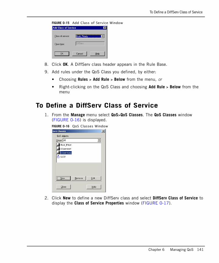
To Define a DiffServ Class of Service
Chapter 6 Managing QoS 141
FIGURE 0-15 Add Class of Service Window
8. Click OK. A DiffServ class header appears in the Rule Base.
9. Add rules under the QoS Class you defined, by either:
• Choosing Rules > Add Rule > Below from the menu, or
• Right-clicking on the QoS Class and choosing Add Rule > Below from the menu
To Define a DiffServ Class of Service1. From the Manage menu select QoS>QoS Classes. The QoS Classes window
(FIGURE 0-16) is displayed.FIGURE 0-16 QoS Classes Window
2. Click New to define a new DiffServ class and select DiffServ Class of Service to display the Class of Service Properties window (FIGURE 0-17).
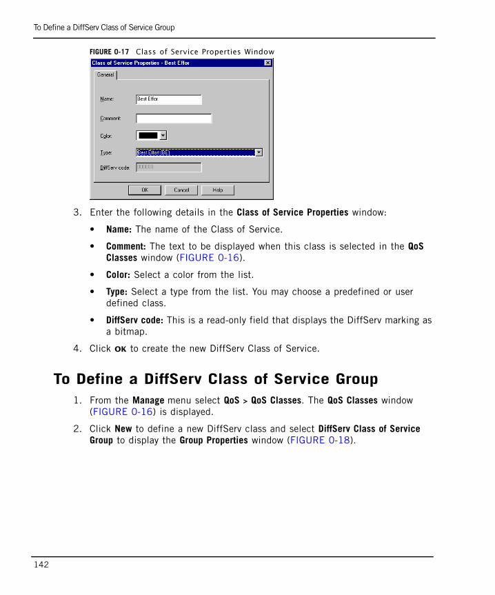
To Define a DiffServ Class of Service Group
142
FIGURE 0-17 Class of Service Properties Window
3. Enter the following details in the Class of Service Properties window:
• Name: The name of the Class of Service.
• Comment: The text to be displayed when this class is selected in the QoS Classes window (FIGURE 0-16).
• Color: Select a color from the list.
• Type: Select a type from the list. You may choose a predefined or user defined class.
• DiffServ code: This is a read-only field that displays the DiffServ marking as a bitmap.
4. Click OK to create the new DiffServ Class of Service.
To Define a DiffServ Class of Service Group1. From the Manage menu select QoS > QoS Classes. The QoS Classes window
(FIGURE 0-16) is displayed.
2. Click New to define a new DiffServ class and select DiffServ Class of Service Group to display the Group Properties window (FIGURE 0-18).
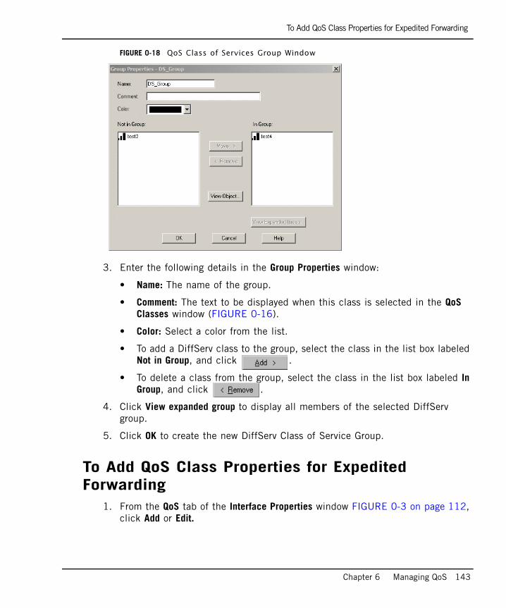
To Add QoS Class Properties for Expedited Forwarding
Chapter 6 Managing QoS 143
FIGURE 0-18 QoS Class of Services Group Window
3. Enter the following details in the Group Properties window:
• Name: The name of the group.
• Comment: The text to be displayed when this class is selected in the QoS Classes window (FIGURE 0-16).
• Color: Select a color from the list.
• To add a DiffServ class to the group, select the class in the list box labeled Not in Group, and click .
• To delete a class from the group, select the class in the list box labeled In Group, and click .
4. Click View expanded group to display all members of the selected DiffServ group.
5. Click OK to create the new DiffServ Class of Service Group.
To Add QoS Class Properties for Expedited Forwarding
1. From the QoS tab of the Interface Properties window FIGURE 0-3 on page 112, click Add or Edit.
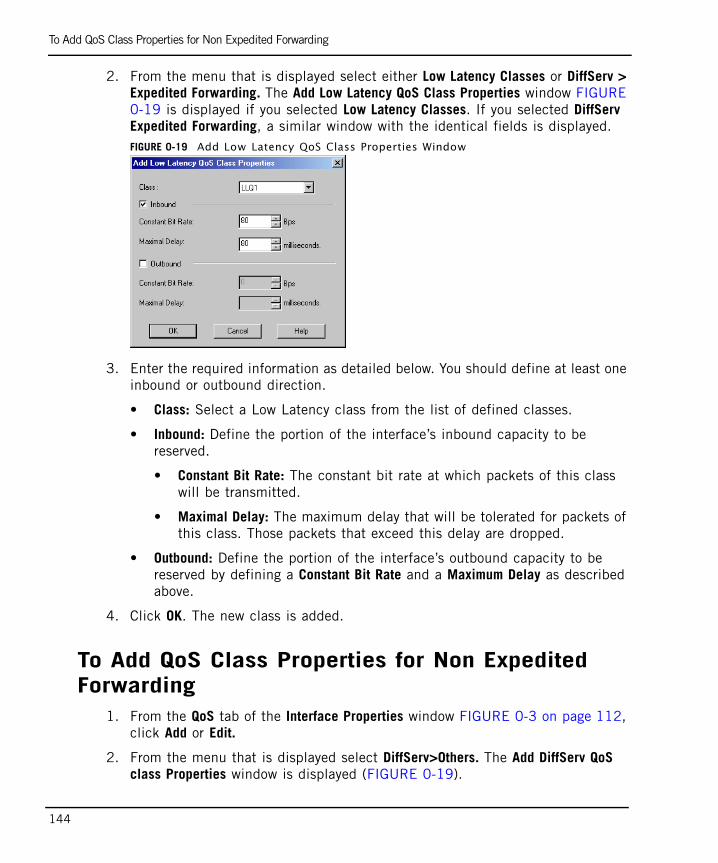
To Add QoS Class Properties for Non Expedited Forwarding
144
2. From the menu that is displayed select either Low Latency Classes or DiffServ > Expedited Forwarding. The Add Low Latency QoS Class Properties window FIGURE 0-19 is displayed if you selected Low Latency Classes. If you selected DiffServ Expedited Forwarding, a similar window with the identical fields is displayed.FIGURE 0-19 Add Low Latency QoS Class Properties Window
3. Enter the required information as detailed below. You should define at least one inbound or outbound direction.
• Class: Select a Low Latency class from the list of defined classes.
• Inbound: Define the portion of the interface’s inbound capacity to be reserved.
• Constant Bit Rate: The constant bit rate at which packets of this class will be transmitted.
• Maximal Delay: The maximum delay that will be tolerated for packets of this class. Those packets that exceed this delay are dropped.
• Outbound: Define the portion of the interface’s outbound capacity to be reserved by defining a Constant Bit Rate and a Maximum Delay as described above.
4. Click OK. The new class is added.
To Add QoS Class Properties for Non Expedited Forwarding
1. From the QoS tab of the Interface Properties window FIGURE 0-3 on page 112, click Add or Edit.
2. From the menu that is displayed select DiffServ>Others. The Add DiffServ QoS class Properties window is displayed (FIGURE 0-19).
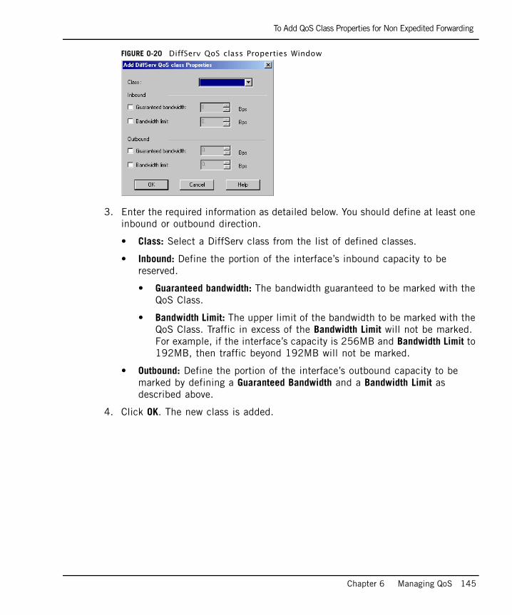
To Add QoS Class Properties for Non Expedited Forwarding
Chapter 6 Managing QoS 145
FIGURE 0-20 DiffServ QoS class Properties Window
3. Enter the required information as detailed below. You should define at least one inbound or outbound direction.
• Class: Select a DiffServ class from the list of defined classes.
• Inbound: Define the portion of the interface’s inbound capacity to be reserved.
• Guaranteed bandwidth: The bandwidth guaranteed to be marked with the QoS Class.
• Bandwidth Limit: The upper limit of the bandwidth to be marked with the QoS Class. Traffic in excess of the Bandwidth Limit will not be marked. For example, if the interface’s capacity is 256MB and Bandwidth Limit to 192MB, then traffic beyond 192MB will not be marked.
• Outbound: Define the portion of the interface’s outbound capacity to be marked by defining a Guaranteed Bandwidth and a Bandwidth Limit as described above.
4. Click OK. The new class is added.
Working with Low Latency Classes
146
Working with Low Latency ClassesQoS Low Latency Queuing makes it possible to define special classes of service for “delay sensitive” applications like voice and video. Rules under these classes can be used together with other rules in the QoS Policy Rule Base. Low Latency classes require you to specify the maximal delay that is tolerated and a Constant Bit Rate. QoS then guarantees that traffic matching rules of this type are forwarded within the limits of the bounded delay.
For more detailed information, please see “Low Latency Queuing” on page 91.
In This Section
To Implement Low Latency QueuingHaving defined one or more Low Latency Classes of Service, you can implement Low Latency Queuing as follows:
1. In the QoS tab of the Interface Properties window of all interfaces on which Low Latency classes are implemented (see “Specifying Interface QoS Properties” on page 110), click Add under DiffServ and Low Latency classes to add a new class, or Edit to edit the properties of an existing class.
2. In the Add QoS Class Properties window (FIGURE 0-19 on page 144), select the Low Latency class and define the Inbound and Outbound parameters (see “To Add QoS Class Properties for Expedited Forwarding” on page 143).
3. Click OK. You can now add Low Latency Classes to the QoS Policy Rule Base.
4. Right-click in the Name column of a rule and choose Add Class of Service, or choose Add QoS Class from the Rules menu.
5. Specify whether the class should appear above or below the rule in the Rule Base.
To Implement Low Latency Queuing page 146
To Define Low Latency Classes of Service page 147
To Define Class of Service Properties for Low Latency Queuing page 147
Note - The order of the classes in the Rule Base must be DiffServ, followed by Low Latency, and then Best Effort. You will not be able to add a Low Latency class to the Rule Base above any DiffServ classes you may have.
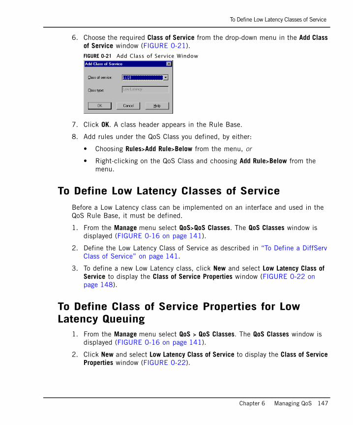
To Define Low Latency Classes of Service
Chapter 6 Managing QoS 147
6. Choose the required Class of Service from the drop-down menu in the Add Class of Service window (FIGURE 0-21).FIGURE 0-21 Add Class of Service Window
7. Click OK. A class header appears in the Rule Base.
8. Add rules under the QoS Class you defined, by either:
• Choosing Rules>Add Rule>Below from the menu, or
• Right-clicking on the QoS Class and choosing Add Rule>Below from the menu.
To Define Low Latency Classes of ServiceBefore a Low Latency class can be implemented on an interface and used in the QoS Rule Base, it must be defined.
1. From the Manage menu select QoS>QoS Classes. The QoS Classes window is displayed (FIGURE 0-16 on page 141).
2. Define the Low Latency Class of Service as described in “To Define a DiffServ Class of Service” on page 141.
3. To define a new Low Latency class, click New and select Low Latency Class of Service to display the Class of Service Properties window (FIGURE 0-22 on page 148).
To Define Class of Service Properties for Low Latency Queuing
1. From the Manage menu select QoS > QoS Classes. The QoS Classes window is displayed (FIGURE 0-16 on page 141).
2. Click New and select Low Latency Class of Service to display the Class of Service Properties window (FIGURE 0-22).
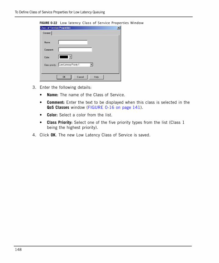
To Define Class of Service Properties for Low Latency Queuing
148
FIGURE 0-22 Low latency Class of Service Properties Window
3. Enter the following details:
• Name: The name of the Class of Service.
• Comment: Enter the text to be displayed when this class is selected in the QoS Classes window (FIGURE 0-16 on page 141).
• Color: Select a color from the list.
• Class Priority: Select one of the five priority types from the list (Class 1 being the highest priority).
4. Click OK. The new Low Latency Class of Service is saved.
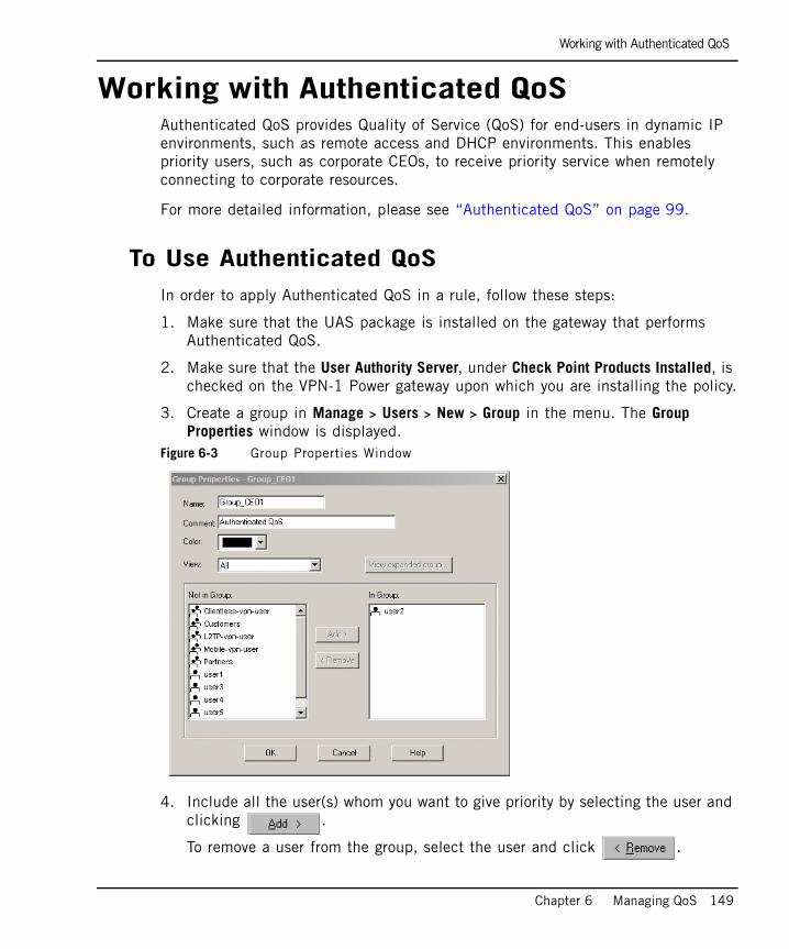
Working with Authenticated QoS
Chapter 6 Managing QoS 149
Working with Authenticated QoSAuthenticated QoS provides Quality of Service (QoS) for end-users in dynamic IP environments, such as remote access and DHCP environments. This enables priority users, such as corporate CEOs, to receive priority service when remotely connecting to corporate resources.
For more detailed information, please see “Authenticated QoS” on page 99.
To Use Authenticated QoSIn order to apply Authenticated QoS in a rule, follow these steps:
1. Make sure that the UAS package is installed on the gateway that performs Authenticated QoS.
2. Make sure that the User Authority Server, under Check Point Products Installed, is checked on the VPN-1 Power gateway upon which you are installing the policy.
3. Create a group in Manage > Users > New > Group in the menu. The Group Properties window is displayed.
Figure 6-3 Group Properties Window
4. Include all the user(s) whom you want to give priority by selecting the user and clicking .
To remove a user from the group, select the user and click .
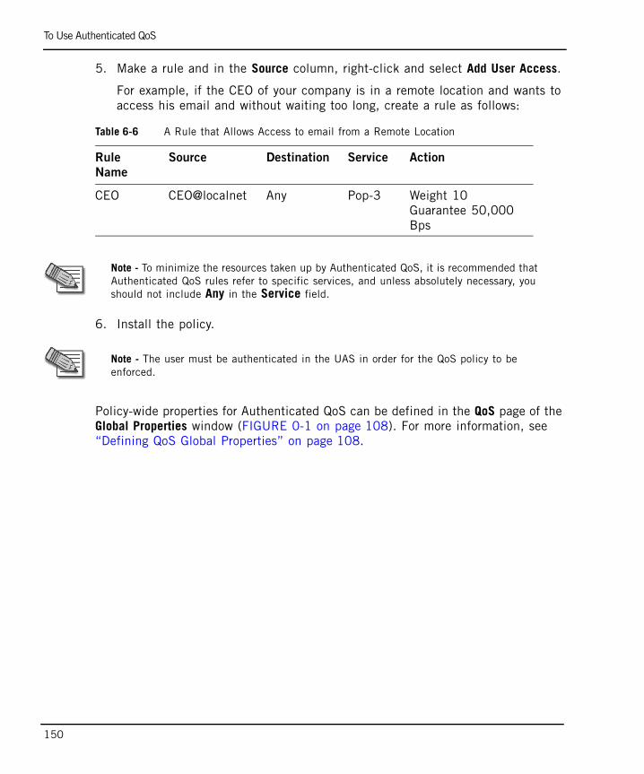
To Use Authenticated QoS
150
5. Make a rule and in the Source column, right-click and select Add User Access.
For example, if the CEO of your company is in a remote location and wants to access his email and without waiting too long, create a rule as follows:
6. Install the policy.
Policy-wide properties for Authenticated QoS can be defined in the QoS page of the Global Properties window (FIGURE 0-1 on page 108). For more information, see “Defining QoS Global Properties” on page 108.
Table 6-6 A Rule that Allows Access to email from a Remote Location
Rule
Name
Source Destination Service Action
CEO CEO@localnet Any Pop-3 Weight 10Guarantee 50,000 Bps
Note - To minimize the resources taken up by Authenticated QoS, it is recommended that Authenticated QoS rules refer to specific services, and unless absolutely necessary, you should not include Any in the Service field.
Note - The user must be authenticated in the UAS in order for the QoS policy to be enforced.
Managing QoS for Citrix ICA Applications
Chapter 6 Managing QoS 151
Managing QoS for Citrix ICA ApplicationsIn order to deliver a QoS solution for the Citrix ICA protocol, complete the following procedures:
1. Disable session sharing in the Citrix Program Neighborhood.
2. Modify your Security Policy to allow the Citrix_ICA and Citrix_ICA_Browsing services.
3. Discover the Citrix application names, as defined by the Citrix Administrator, and retrieve your Citrix ICA application names from the SmartView Tracker. This includes turning on the application detection check box and installing Security and QoS Policies.
4. Define new Citrix TCP services with the application names you have detected.
5. Add the appropriate Citrix TCP services to rules in your QoS Policy.
6. Install the QoS Policy.
In This Section
Disabling Session SharingCitrix enables session sharing by default. In this mode, traffic from all the applications used by a specific client share the same TCP connection. In order for QoS to prioritize different Citrix ICA applications from the same client, you must disable session sharing. This means that every application uses a separate TCP connection (all going to the same server port, 1494, from different source ports).
You should contact the Citrix Administrator to configure the correct mode.
Note - The Any service does not include the Citrix ICA service.
Disabling Session Sharing page 151
Modifying your Security Policy page 152
Discovering Citrix ICA Application Names page 152
Defining a New Citrix TCP Service page 155
Adding a Citrix TCP Service to a Rule (Traditional Mode Only) page 156
Installing the Security and QoS Policies page 156
Modifying your Security Policy
152
To Disable Session Sharing:1. Double-click the Citrix Program Neighborhood icon placed on the desktop by the
Citrix install program.
2. Click the Settings icon or select Application Set Settings from the File menu.
3. Select the Default Options tab.
4. Select something other than Seamless Window from the Window Size list.
Modifying your Security Policy You must modify your Security Policy to enable the new Citrix_ICA TCP and Citrix_ICA_Browsing UDP services. The Citrix_ICA service initializes the stateful inspection of the Citrix ICA protocol. The Citrix_ICA service is not included in the Any service of the Security Policy and must therefore be enabled in one of the following ways:
• In the Security tab add a rule to your Security Policy with the Citrix_ICA TCP service. Similarly, add a rule for the Citrix_ICA_Browsing service. Alternatively, you can add simply add the Citrix_metaFrame group, which incorporates both the Citrix_ICA TCP and Citrix_ICA_Browsing UDP services.
OR
1. Expand the TCP branch of the Services Tree. Double-click on the Citrix_ICA service. The TCP Service Properties - Citrix _ICA window is displayed.
2. Click Advanced. The Advanced TCP Service Properties window is displayed.
3. Check Match for Any to turn on the Citrix ICA protocol inspection without having to add a specific rule for the Citrix_ICA service (if the Any service is allowed).
Discovering Citrix ICA Application NamesIn order to discover the Citrix ICA application name, as defined by the Citrix Administrator, use QoS to snoop the wire and send logs (of type alert) to the SmartView Tracker, recording the Citrix ICA application name. The Citrix ICA application detection is turned off by default.
Note - The frequency of recording an application name log (alert) is 24 hours.
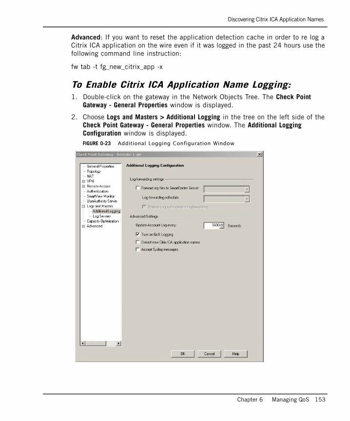
Discovering Citrix ICA Application Names
Chapter 6 Managing QoS 153
Advanced: If you want to reset the application detection cache in order to re log a Citrix ICA application on the wire even if it was logged in the past 24 hours use the following command line instruction:
fw tab -t fg_new_citrix_app -x
To Enable Citrix ICA Application Name Logging:1. Double-click on the gateway in the Network Objects Tree. The Check Point
Gateway - General Properties window is displayed.
2. Choose Logs and Masters > Additional Logging in the tree on the left side of the Check Point Gateway - General Properties window. The Additional Logging Configuration window is displayed.FIGURE 0-23 Additional Logging Configuration Window
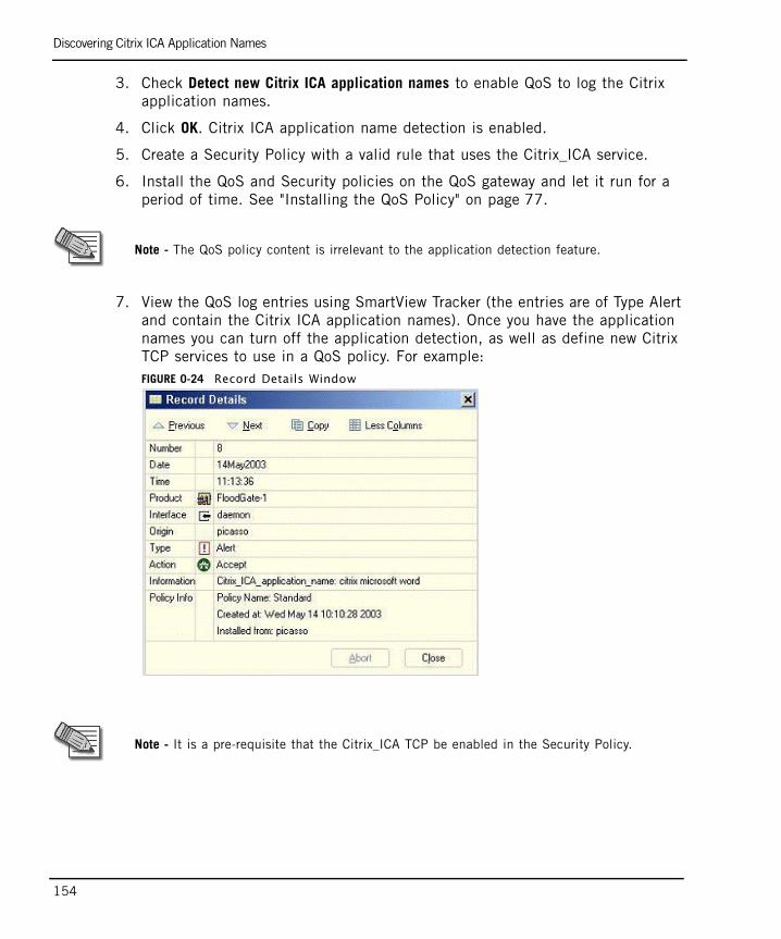
Discovering Citrix ICA Application Names
154
3. Check Detect new Citrix ICA application names to enable QoS to log the Citrix application names.
4. Click OK. Citrix ICA application name detection is enabled.
5. Create a Security Policy with a valid rule that uses the Citrix_ICA service.
6. Install the QoS and Security policies on the QoS gateway and let it run for a period of time. See "Installing the QoS Policy" on page 77.
7. View the QoS log entries using SmartView Tracker (the entries are of Type Alert and contain the Citrix ICA application names). Once you have the application names you can turn off the application detection, as well as define new Citrix TCP services to use in a QoS policy. For example:FIGURE 0-24 Record Details Window
Note - The QoS policy content is irrelevant to the application detection feature.
Note - It is a pre-requisite that the Citrix_ICA TCP be enabled in the Security Policy.
Defining a New Citrix TCP Service
Chapter 6 Managing QoS 155
To Disable Citrix ICA Application Name Logging:1. Double-click on the gateway in the Network Objects Tree. The Check Point
Gateway - General Properties window is displayed.
2. Choose Logs and Masters > Additional Logging in the tree on the left side of the Check Point Gateway - General Properties window. The Additional Logging Configuration window is displayed.
3. Uncheck Detect new Citrix ICA application names so that QoS will not log the Citrix application names.
4. Click OK. Citrix ICA application name detection is disabled.
5. Install the QoS Policy.
Defining a New Citrix TCP ServiceA new service type was introduced in the Smart DashBoard, Citrix TCP.
To Define a New Citrix TCP Service1. Right-click on the Citrix TCP branch of the Services Tree, and select New Citrix
TCP. The Citrix Service Properties window is displayed.
2. Enter the following details in the Citrix Service Properties window, as shown in the example below:
• Name: The name of the new service.
• Comment: A comment describing the new service.
• Color: Select a color from the list.
• Application: The exact name (case insensitive) of the Citrix Application.
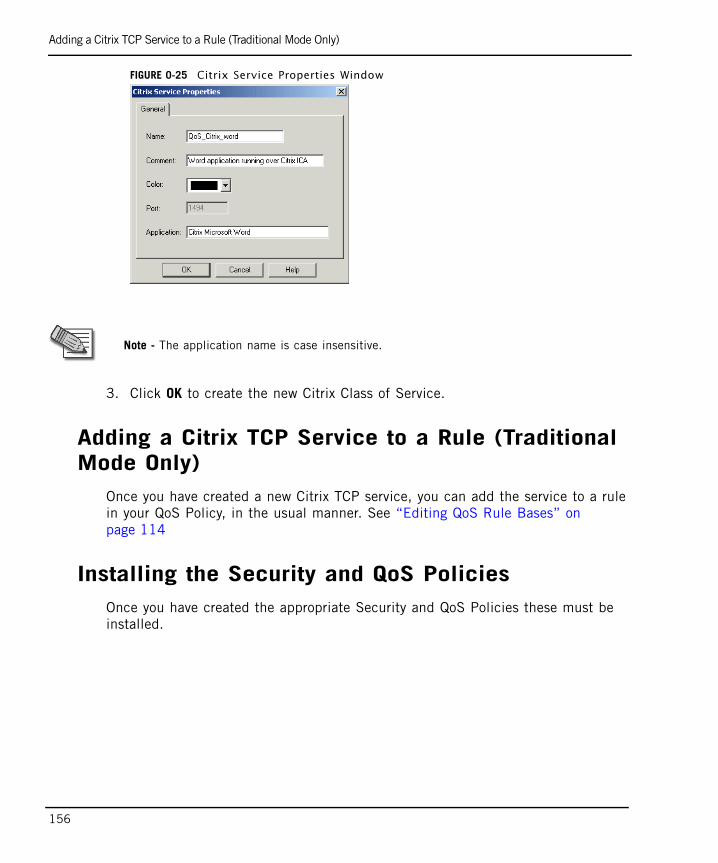
Adding a Citrix TCP Service to a Rule (Traditional Mode Only)
156
FIGURE 0-25 Citrix Service Properties Window
3. Click OK to create the new Citrix Class of Service.
Adding a Citrix TCP Service to a Rule (Traditional Mode Only)
Once you have created a new Citrix TCP service, you can add the service to a rule in your QoS Policy, in the usual manner. See “Editing QoS Rule Bases” on page 114
Installing the Security and QoS PoliciesOnce you have created the appropriate Security and QoS Policies these must be installed.
Note - The application name is case insensitive.
Managing QoS for Citrix Printing
Chapter 6 Managing QoS 157
Managing QoS for Citrix PrintingIn This Section
Printing generates relatively large quantities of data, causing the TCP connection to consume excessive quantities of bandwidth. Clearly, from a QoS perspective this type of connection should be identified and the bandwidth made available to these connections should be limited.
There are three primary methods of printing in the MetaFrame environment, IP Network printing, MetaFrame Auto-Creation of printers and local MetaFrame printing.
QoS provides a solution for printing traffic using the MetaFrame Auto-Creation of printers printing method, by classifying each ICA connection as either a printing or a non-printing connection.
A connection that is classified as printing is assigned to a Citrix printing rule. This rule can be configured to limit printing traffic and thus avoid excessive consumption of bandwidth. A connection that is classified as non-printing is assigned to a rule according to the regular matching method.
Classification of the connection is dynamic and is based on examining the ICA priority bits of each packet. An ICA connection is therefore matched dynamically to one of 2 different rules depending on the type of data passing through the connection at any point in time.
It is recommended that you limit the bandwidth per connection for printing to 25Kbps. This value represents the average bandwidth utilization of a single non-printing Citrix ICA session versus an additional 150Kbps of bandwidth per session that printing often requires. This preserves bandwidth for other traffic.
Configuring a Citrix Printing Rule (Traditional Mode Only)
Define a printing rule to which all ICA connections that are in a printing state are assigned.
Configuring a Citrix Printing Rule (Traditional Mode Only) page 157
Configuring QoS Topology page 158
Configuring QoS Topology
158
To Configure a Citrix Printing Rule1. Position your cursor in the Name field of the QoS tab, at the position where you
want to add a new rule.
2. Right-click and select one of the Add Rule options. The Rule Name window is displayed.
3. Enter the rule name in the Rule Name field.
4. Click OK to save the rule name.
5. Right-click in the Service column and select Add. The Add Object window is displayed, listing the network objects defined in the Security Policy and the QoS Policy.
6. Select the predefined Citrix_ICA_printing service and click OK. The service is added to the rule.
7. Right-click in the Action column and select Edit Properties. The QoS Action Properties window is displayed.
8. Select Advanced in the Action Type area.
9. Select Per connection limit in the Limit area.
10. Enter a per connection limit of 25 Kbps in the Per connection limit field (recommended).
11. Click OK.
Configuring QoS TopologyWhen the MetaFrame Auto-Creation of printers printing method is used, the Citrix printing traffic passes from the Citrix Server to the Citrix Client. To enforce QoS on this traffic, QoS must be installed on the Gateway external interface on the inbound direction, or on the Gateway internal interface on the outbound direction, that is, Flood-Gate-1 must be able to "see" the traffic passing from the Citrix Server to the Citrix Client.
Viewing QoS Gateway Status
Chapter 6 Managing QoS 159
Viewing QoS Gateway Status
Display QoS Gateways Controlled by SmartCenter Use the SmartView Status application and the SmartView Monitor. For information about the Check Point SmartView Status, see the SmartCenter Administration Guide.
Enabling Log Collection
160
Enabling Log CollectionIn order for a connection to be logged, the QoS logging flag must be turned on and the connection’s matching rule must be marked with either Log or Account in the Track field of the rule. For further information on how QoS’s logging features work see “Overview of Logging” on page 164.
In This Section
To Turn on QoS LoggingA QoS gateway logs to the log if Turn on QoS Logging is checked in the Additional Logging page (under Logs and Masters) of the QoS gateway’s Properties window (Figure 6-4 on page 161). By default Qos Logging is turned on.
To Turn on QoS Logging page 160
To Confirm that the Rule is Marked for Logging page 161
To Start SmartView Tracker page 162
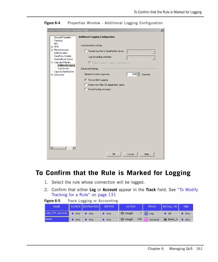
To Confirm that the Rule is Marked for Logging
Chapter 6 Managing QoS 161
Figure 6-4 Properties Window - Additional Logging Configuration
To Confirm that the Rule is Marked for Logging1. Select the rule whose connection will be logged.
2. Confirm that either Log or Account appear in the Track field. See “To Modify Tracking for a Rule” on page 131
Figure 6-5 Track Logging or Accounting
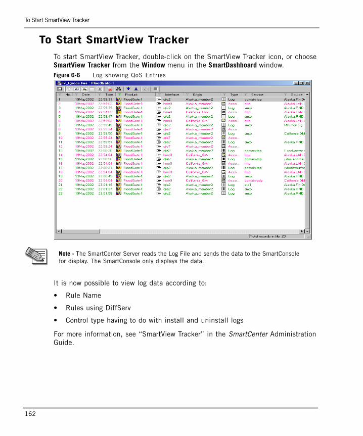
To Start SmartView Tracker
162
To Start SmartView TrackerTo start SmartView Tracker, double-click on the SmartView Tracker icon, or choose
SmartView Tracker from the Window menu in the SmartDashboard window.Figure 6-6 Log showing QoS Entries
It is now possible to view log data according to:
• Rule Name
• Rules using DiffServ
• Control type having to do with install and uninstall logs
For more information, see “SmartView Tracker” in the SmartCenter Administration Guide.
Note - The SmartCenter Server reads the Log File and sends the data to the SmartConsole for display. The SmartConsole only displays the data.
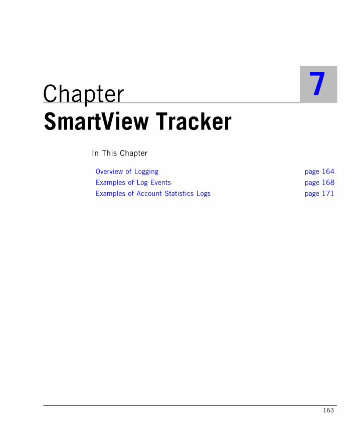
163
Chapter 7SmartView Tracker
In This Chapter
Overview of Logging page 164
Examples of Log Events page 168
Examples of Account Statistics Logs page 171
Overview of Logging
164
Overview of LoggingThe SmartView Tracker enables you to view entries in the Log File. Each entry in the Log File is a record of an event or an account record. The SmartView Tracker gives you control over the information displayed in the Log File. You can navigate through the Log File and select the log entries that you would like to display. You can view the log entries for all the installed Check Point products or for a selected product, such as QoS or VPN.
Two types of events are logged. Table 7-1 on page 165 describes the features unique to event logs and Table 7-1 on page 167 describes the features unique to accounting logs.
The following two conditions must be met for a connection to be logged:
• The QoS logging checkbox must be selected in the Gateway Properties - Additional Logging Configuration window shown in Figure 6-4 on page 161 must be selected. (By default this is automatically selected.)
• The connection’s matching rule must be marked with either Log or Account in the Track field of the rule. Refer to “To Confirm that the Rule is Marked for Logging” on page 161 and “To Modify Tracking for a Rule” on page 131.
Further information on how to start the SmartView Tracker can be found in “Enabling Log Collection” on page 160.
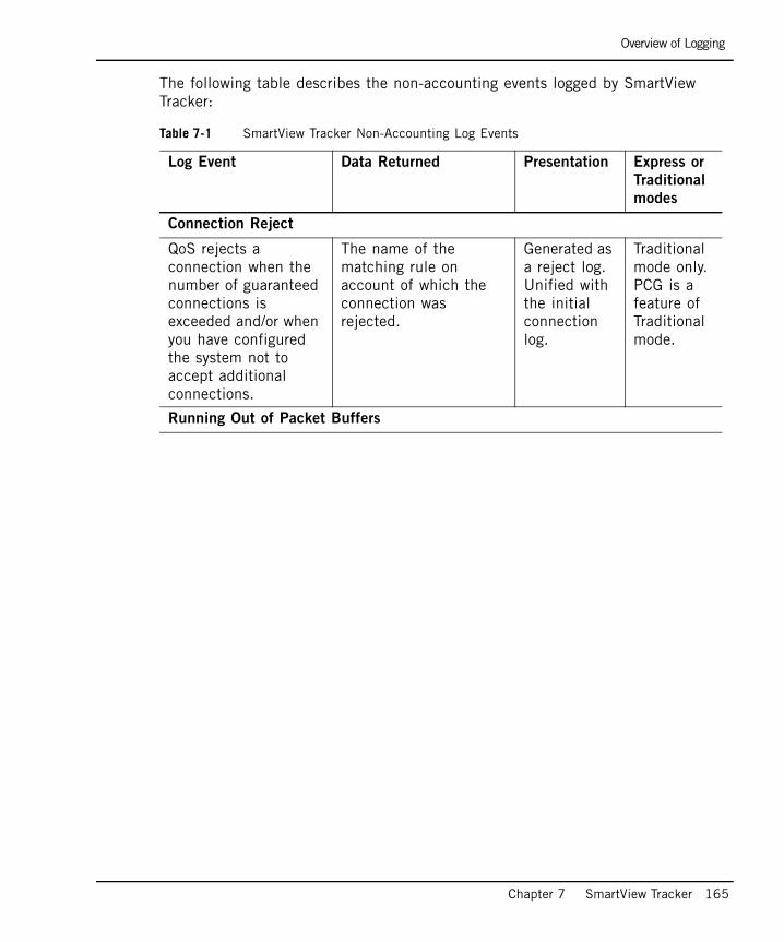
Overview of Logging
Chapter 7 SmartView Tracker 165
The following table describes the non-accounting events logged by SmartView Tracker:
Table 7-1 SmartView Tracker Non-Accounting Log Events
Log Event Data Returned Presentation Express or
Traditional
modes
Connection Reject
QoS rejects a connection when the number of guaranteed connections is exceeded and/or when you have configured the system not to accept additional connections.
The name of the matching rule on account of which the connection was rejected.
Generated as a reject log. Unified with the initial connection log.
Traditional mode only. PCG is a feature of Traditional mode.
Running Out of Packet Buffers
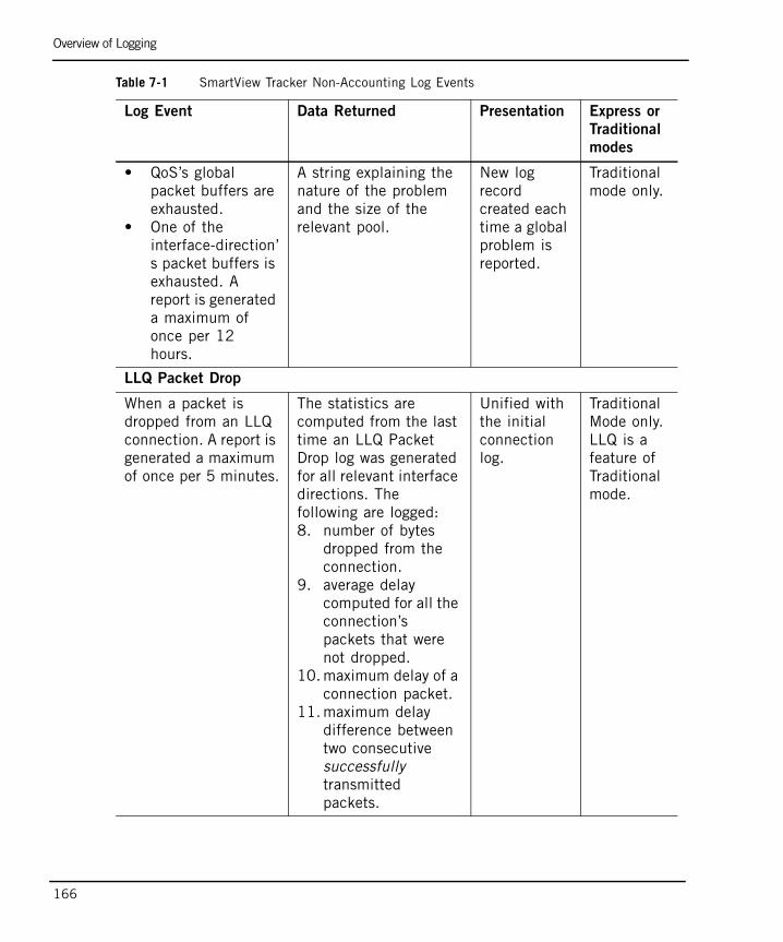
Overview of Logging
166
• QoS’s global packet buffers are exhausted.
• One of the interface-direction’s packet buffers is exhausted. A report is generated a maximum of once per 12 hours.
A string explaining the nature of the problem and the size of the relevant pool.
New log record created each time a global problem is reported.
Traditional mode only.
LLQ Packet Drop
When a packet is dropped from an LLQ connection. A report is generated a maximum of once per 5 minutes.
The statistics are computed from the last time an LLQ Packet Drop log was generated for all relevant interface directions. The following are logged:8. number of bytes
dropped from the connection.
9. average delay computed for all the connection’s packets that were not dropped.
10. maximum delay of a connection packet.
11. maximum delay difference between two consecutive successfully transmitted packets.
Unified with the initial connection log.
Traditional Mode only. LLQ is a feature of Traditional mode.
Table 7-1 SmartView Tracker Non-Accounting Log Events
Log Event Data Returned Presentation Express or
Traditional
modes
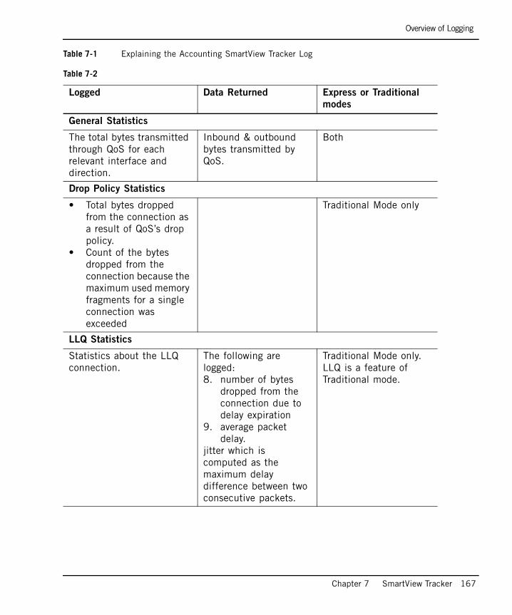
Overview of Logging
Chapter 7 SmartView Tracker 167
Table 7-1 Explaining the Accounting SmartView Tracker Log
Table 7-2
Logged Data Returned Express or Traditional
modes
General Statistics
The total bytes transmitted through QoS for each relevant interface and direction.
Inbound & outbound bytes transmitted by QoS.
Both
Drop Policy Statistics
• Total bytes dropped from the connection as a result of QoS’s drop policy.
• Count of the bytes dropped from the connection because the maximum used memory fragments for a single connection was exceeded
Traditional Mode only
LLQ Statistics
Statistics about the LLQ connection.
The following are logged:8. number of bytes
dropped from the connection due to delay expiration
9. average packet delay.
jitter which is computed as the maximum delay difference between two consecutive packets.
Traditional Mode only. LLQ is a feature of Traditional mode.
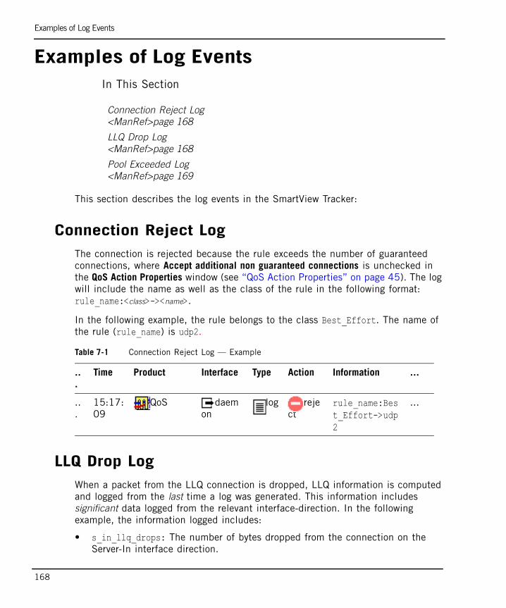
Examples of Log Events
168
Examples of Log EventsIn This Section
This section describes the log events in the SmartView Tracker:
Connection Reject LogThe connection is rejected because the rule exceeds the number of guaranteed connections, where Accept additional non guaranteed connections is unchecked in the QoS Action Properties window (see “QoS Action Properties” on page 45). The log will include the name as well as the class of the rule in the following format: rule_name:<class>-><name>.
In the following example, the rule belongs to the class Best_Effort. The name of the rule (rule_name) is udp2.
LLQ Drop LogWhen a packet from the LLQ connection is dropped, LLQ information is computed and logged from the last time a log was generated. This information includes significant data logged from the relevant interface-direction. In the following example, the information logged includes:
• s_in_llq_drops: The number of bytes dropped from the connection on the Server-In interface direction.
Connection Reject Log<ManRef>page 168
LLQ Drop Log<ManRef>page 168
Pool Exceeded Log<ManRef>page 169
Table 7-1 Connection Reject Log — Example
..
.
Time Product Interface Type Action Information ...
..
.15:17:09
QoS daemon
log reject
rule_name:Best_Effort->udp2
...
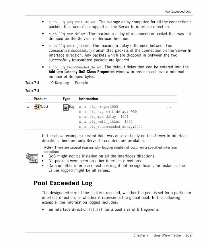
Pool Exceeded Log
Chapter 7 SmartView Tracker 169
• s_in_llq_avg_xmit_delay: The average delay computed for all the connection's packets that were not dropped on the Server-In interface direction.
• s_in_llq_max_delay: The maximum delay of a connection packet that was not dropped on the Server-In interface direction.
• s_in_llq_xmit_jitter: The maximum delay difference between two consecutive successfully transmitted packets of the connection on the Server-In interface direction. Any packets which are dropped in between the two successfully transmitted packets are ignored.
• s_in_llq_recommended_delay: The default delay that can be entered into the Add Low Latency QoS Class Properties window in order to achieve a minimal number of dropped bytes.
Table 7-2 LLQ Drop Log — Example
In the above example relevant data was observed only on the Server-In interface direction, therefore only Server-In counters are available.
Pool Exceeded Log The designated size of the pool is exceeded, whether the pool is set for a particular interface direction, or whether it represents the global pool. In the following example, the information logged includes:
• an interface direction (ifdir) has a pool size of 8 fragments
Table 7-3
... Product Type Information ...
... QoS log s_in_llq_drops:3000 s_in_llq_avg_xmit_delay: 900 s_in_llq_max_delay: 1351 s_in_llq_xmit_jitter: 1351s_in_llq_recommended_delay:2000
...
Note - There are several reasons why logging might not occur on a specified interface direction:
• QoS might not be installed on all the interfaces directions.• No packets were seen on other interface directions.• Data on other interface directions might not be significant, for instance, the
values logged might be all zeroes.
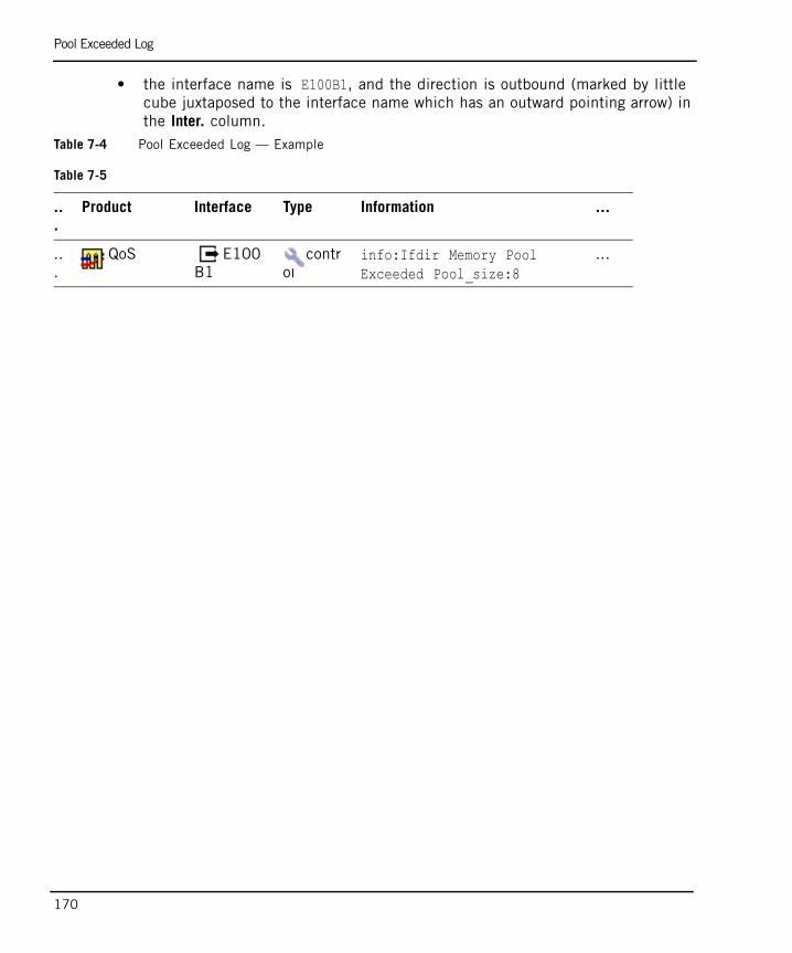
Pool Exceeded Log
170
• the interface name is E100B1, and the direction is outbound (marked by little cube juxtaposed to the interface name which has an outward pointing arrow) in the Inter. column.
Table 7-4 Pool Exceeded Log — Example
Table 7-5
..
.
Product Interface Type Information ...
..
.QoS E100
B1contr
olinfo:Ifdir Memory Pool Exceeded Pool_size:8
...
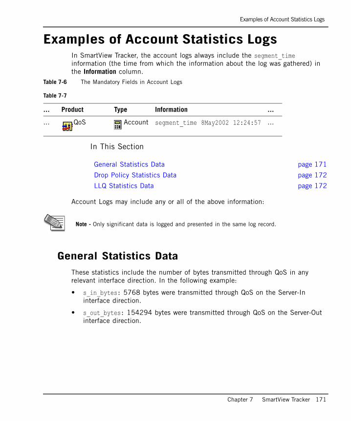
Examples of Account Statistics Logs
Chapter 7 SmartView Tracker 171
Examples of Account Statistics LogsIn SmartView Tracker, the account logs always include the segment_time information (the time from which the information about the log was gathered) in the Information column.
Table 7-6 The Mandatory Fields in Account Logs
In This Section
Account Logs may include any or all of the above information:
General Statistics DataThese statistics include the number of bytes transmitted through QoS in any relevant interface direction. In the following example:
• s_in_bytes: 5768 bytes were transmitted through QoS on the Server-In interface direction.
• s_out_bytes: 154294 bytes were transmitted through QoS on the Server-Out interface direction.
Table 7-7
... Product Type Information ...
... QoS Account segment_time 8May2002 12:24:57 ...
General Statistics Data page 171
Drop Policy Statistics Data page 172
LLQ Statistics Data page 172
Note - Only significant data is logged and presented in the same log record.

Drop Policy Statistics Data
172
Table 7-8 General Statistics Data — Example
Drop Policy Statistics DataThe number of bytes dropped from the connection in any relevant interface direction as a result of drop policy are logged. The drop policy is aimed at managing QoS packet buffers, see “WFRED (Weighted Flow Random Early Drop)” on page 30. This includes the total number of bytes dropped from the connection since it exceeded its allocation. In the following example:
• s_out_total_drops: 3914274 bytes were dropped from the connection as a result of drop policy, on the Server-Out interface direction.
• s_out_exceed_drops: Out of total number of drops (s_out_total_drops) 3914274 bytes were dropped from the connection because it exceeded its allowed number of fragments, on the Server-Out interface direction.
Table 7-10 Drop Policy Statistics Data — Example
LLQ Statistics Data Data items are the same as in “LLQ Drop Log” on page 168, but are computed from the beginning of the connection and not from the last time a log was generated.
Table 7-9
... Information ...
... s_in_bytes:5768 s_out_bytes: 154294
...
Table 7-11
... Information ...
... s_out_total_drops:3914274 s_out_exceed_drops: 3914274
...
173
Chapter 8Command Line Interface
In This Chapter
QoS Commands page 174
Setup page 175
fgate Menu page 176
Control page 177
Monitor page 179
Utilities page 181
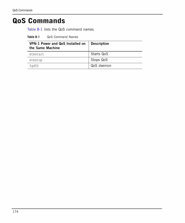
QoS Commands
174
QoS CommandsTable 8-1 lists the QoS command names.
Table 8-1 QoS Command Names
VPN-1 Power and QoS Installed on
the Same Machine
Description
etmstart Starts QoS
etmstop Stops QoS
fgd50 QoS daemon
Setup
Chapter 8 Command Line Interface 175
SetupIn This Section
cpstart and cpstopGenerally, to stop and start the QoS gateway you are required to stop the VPN-1 Power using the cpstop and cpstart commands. In the event that you would like to stop the QoS gateway only, you can use the QoS specific etmstart and etmstop commands. For more on cpstop and cpstart, see the SmartCenter Administration Guide.
etmstartetmstart loads the QoS gateway, starts the QoS daemon (fgd50), and retrieves the last policy that was installed on the QoS gateway.
etmstopetmstop kills the QoS daemon (fgd50) and then unloads the QoS policy and gateway.
cpstart and cpstop page 175
etmstart page 175
etmstop page 175
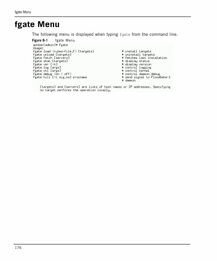
fgate Menu
176
fgate MenuThe following menu is displayed when typing fgate from the command line.Figure 8-1 fgate Menu
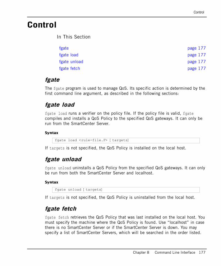
Control
Chapter 8 Command Line Interface 177
ControlIn This Section
fgateThe fgate program is used to manage QoS. Its specific action is determined by the first command line argument, as described in the following sections:
fgate loadfgate load runs a verifier on the policy file. If the policy file is valid, fgate compiles and installs a QoS Policy to the specified QoS gateways. It can only be run from the SmartCenter Server.
Syntax
If targets is not specified, the QoS Policy is installed on the local host.
fgate unloadfgate unload uninstalls a QoS Policy from the specified QoS gateways. It can only be run from both the SmartCenter Server and localhost.
Syntax
If targets is not specified, the QoS Policy is uninstalled from the local host.
fgate fetchfgate fetch retrieves the QoS Policy that was last installed on the local host. You must specify the machine where the QoS Policy is found. Use “localhost” in case there is no SmartCenter Server or if the SmartCenter Server is down. You may specify a list of SmartCenter Servers, which will be searched in the order listed.
fgate page 177
fgate load page 177
fgate unload page 177
fgate fetch page 177
fgate load <rule-file.F> [targets]
fgate unload [targets]
Control
178
fgate fetch -f attempts to retrieve policies from all management stations, one after the other until it succeeds. If the gateway fails to retrieve a policy from a SmartCenter Server, it tries to retrieve one from itself.
Syntax
Examples
fgate fetch [-f | servers]
fgate fetch localhostfgate fetch -ffgate fetch mgmt_server_name
Monitor
Chapter 8 Command Line Interface 179
MonitorIn This Section
fgate statfgate stat displays the status of target hosts in various formats. If this command is launched from a SmartCenter server this command can be run on an array of gateways. If this command is launched from a gateway, the status of the gateway is returned.
Usage
The default format displays the following information for each host: product, version, build number, policy name (Express or Traditional), install time and interfaces number.
If no target is specified, the status of localhost is shown. Example:
fgate stat page 179
fgate ver page 180
fgate stat [targets]
fgate stat
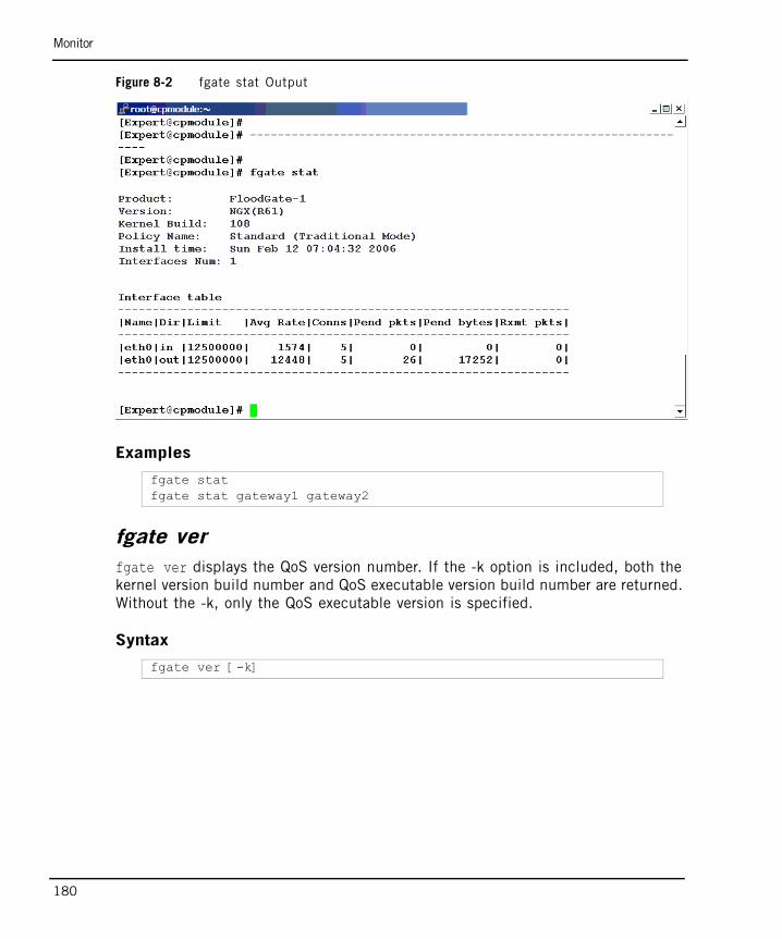
Monitor
180
Figure 8-2 fgate stat Output
Examples
fgate verfgate ver displays the QoS version number. If the -k option is included, both the kernel version build number and QoS executable version build number are returned. Without the -k, only the QoS executable version is specified.
Syntax
fgate statfgate stat gateway1 gateway2
fgate ver [-k]
Utilities
Chapter 8 Command Line Interface 181
UtilitiesIn This Section
fgate logfgate log turns logging on or off in the kernel. It can be used in order to save resources without reinstalling your QoS policy. the stat option returns the current state of logging.
Syntax
By default, fgate log is turned on.
fgate ctlfgate ctl sends control information to the QoS kernel gateway.
Syntax
fgate debugfgate debug turns on a debug flag which sends additional debugging information to the fgd logfile: $FGDIR/log/fgd.elg. The default is off.
fgate log page 181
fgate ctl page 181
fgate debug page 181
fgate kill page 182
fgate log < on | off | stat >
fgate ctl etmreg
parameter meaning
etmreg etmreg is for Unix platforms only. fgate ctl turns on or off the QoS kernel.
Utilities
182
Syntax
fgate killfgate kill sends a signal to a QoS daemon. The SmartCenter Server does not run the QoS daemon therefore this command is valid only on gateways.
Syntax
The QoS daemon writes the pids to files in the log directory upon startup. These files are named $FWDIR/tmp/<daemon_name>.pid. For example, the file containing the pid of the QoS snmp daemon is $FWDIR/log/snmpd.pid.
Examples
The following command:
sends signal 15 to the QoS fgd daemon.
The following command:
sends signal 1 to the QoS fgd daemon.
fgate debug < on | off >
fgate kill [-t sig_no] proc-name
parameter meaning
[-t sig_no] proc-name If the file$FWDIR/tmp/<proc-name>.pid exists, send sig_no to the pid given in the file.If no signal is specified, signal 15 (SIGTERM) is sent.
fgate kill fgd
fgate kill -t 1 fgd
183
Chapter 9FAQ
In This Chapter
IntroductionWhat is QoS? — QoS is a policy-based, Quality of Service (QoS) solution for VPNs, private WANs and Internet links. It optimizes network performance by assigning priority to business-critical applications and end users. QoS is tightly integrated with VPN-1® Pro
How can I comment on this FAQ? — For additional technical information about QoS, consult the SecureKnowledge database athttp://support.checkpoint.com
Where can I find further information regarding QoS? — Find further details about QoS at http://www.checkpoint.com/products/floodgate-1/index.html
Introduction page 183
QoS Basics page 184
Other Check Point Products - Support and Management page 187
Policy Creation page 188
Capacity Planning page 189
Protocol Support page 190
Installation/Backward Compatibility/Licensing/Versions page 190
How do I? page 191
General Issues page 192
QoS Basics
184
Do I have to know how to administrate Provider-1 to manage QoS? — Knowing how to administrate Provider-1 is not mandatory, but prior knowledge of Provider-1 is helpful when working with QoS.
QoS BasicsWhen should I use Traditional mode and when should I use Express mode? —
Traditional mode should be used if you need fine-tuned functionality and enhanced QoS features. Express mode should be selected if your system requires only basic QoS.
What are the benefits of using each mode? — Traditional mode provides you with optimal QoS functionality, whereas Express mode increases performance and needs less CPU and less memory.
Can I change from Express mode to Traditional mode and vice versa? — You can change a policy from Express mode to Traditional mode, however, you cannot change a policy from Traditional mode to Express mode. Therefore it is recommended that if you are unsure which to install, you should begin with Express mode, maintaining the option to transition to Traditional mode, if you find that your policy required heightened QoS functionality.
What is the highest weight I can use in a rule? — Weights are relative. The only limitation is the Maximum weight of rule parameter, which is defined in the Global Properties window under QoS. The default parameter is 1000, but can be changed to any number.
In the example shown in Table 9-1, you can see the significance of the value of the weight allocated in two different policies. In the example both the HTTP and FTP connections initially enjoy an equal share of the available bandwidth, although they each had a weight of 500 in Policy 1 and a weight of 2 in Policy 2.
By adding a third rule to both policies you can significantly change the result. for example, An SMTP connection with a weight of 100 can be added to each policy. Due to the high initial weights used in Policy 1, there is an insignificant change to the amount of bandwidth available for the HTTP connection in Policy 1 + third rule. However, due to the low initial weights used in Policy 2, the amount of bandwidth that is available to the HTTP connection in Policy 2 + third rule is significantly reduced.
Note - This parameter is only used to assist in input validation.
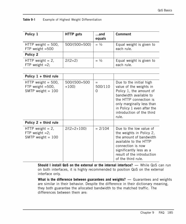
QoS Basics
Chapter 9 FAQ 185
Table 9-1 Example of Highest Weight Differentiation
Should I install QoS on the external or the internal interface? — While QoS can run on both interfaces, it is highly recommended to position QoS on the external interface only.
What is the difference between guarantees and weights? — Guarantees and weights are similar in their behavior. Despite the difference in their dictionary meaning, they both guarantee the allocated bandwidth to the matched traffic. The differences between them are:
Policy 1 HTTP gets ...and
equals
Comment
HTTP weight = 500, FTP weight =500
500/(500+500) = ½ Equal weight is given to each rule.
Policy 2
HTTP weight = 2, FTP weight =2;
2/(2+2) = ½ Equal weight is given to each rule.
Policy 1 + third rule
HTTP weight = 500, FTP weight =500, SMTP weight = 100
500/(500+500+100)
= 500/1100
Due to the initial high value of the weights in Policy 1, the amount of bandwidth available to the HTTP connection is only marginally less than in Policy 1 even after the introduction of the third rule.
Policy 2 + third rule
HTTP weight = 2, FTP weight =2; SMTP weight = 100
2/(2+2+100) = 2/104 Due to the low value of the weights in Policy 2, the amount of bandwidth available to the HTTP connection is now significantly less as a result of the introduction of the third rule.
QoS Basics
186
• Guarantees are stated in absolute numbers (for example, 20000bps) and weights are stated in relative numbers (for example, 100).
• Guarantees are allocated their share of bandwidth before weights. For example if you have a link of 1.5 MB:
Your Rule Base is:
• HTTP Guarantee 1Mb
• FTP Weight 40
• SMTP Weight 10
The result is:
• first 1 MB for HTTP is allocated, then• 0.4 MB for FTP is allocated and 0.1MB for SMTP is allocated.
Use guarantees to define bandwidth in absolute terms or for per connection guarantees.
How does QoS handle TCP retransmitted packets? — When a retransmission is detected, QoS checks to see if the retransmitted data is already contained in the QoS queue. If so, the packet is dropped. This unique QoS capability eliminates retransmissions that consume up to 40% of a WAN link, and saves memory required to store duplicated packets.
Which Firewall resources does QoS support in the Rule Base? — QoS can use its resources to inspect HTTP traffic. Resources are defined using the URI for QoS option and can contain specific URLs or files. For example, you can limit Web surfing to the site http://www.restrict-access-to-this-site.com. You need to add a QOS URI resource that looks for the string “www.restrict-access-to-this-site.com” (without http://). Then use the resource in a QoS rule and add a limit.
Do guarantees waste bandwidth? — No. QoS uses a sophisticated queuing mechanism. An application only takes as much bandwidth as it needs. Any unused bandwidth is then available for use by other applications.
How do I know if loaned bandwidth is available for applications that may need it back? — There is no loaned bandwidth in QoS. Bandwidth that is not utilized by a guarantee/weighted rule is immediately (on a per-packet basis) distributed to the other connections, according to their relative priorities. The important thing to remember is Resolution (referring to level of granularity). QoS allocates bandwidth on a per packet basis. Therefore, only one packet is allocated at a time, resulting in the most accurate scheduling policy.
Other Check Point Products - Support and Management
Chapter 9 FAQ 187
Other Check Point Products - Support and Management
Where is QoS placed in the Provider-1 Inspection chain? — QoS is composed of two components:
• QoS Policy, which is in charge of rule matching
• QoS Scheduling, which is in charge of packet scheduling
Does QoS work With Provider-1? — Yes. One of QoS’s most important features is its unique and sophisticated integration with Provider-1. Its integration features include:
• accurate classification of VPN traffic (inside the VPN tunnel)
• classification of NATed traffic
• shared network objects and topology (that save you time and effort in administration)
• common SmartDashboard with an advanced GUI but a familiar look and feel
• authenticated Quality of Service allows you to assign bandwidth to VPN remote users
• DiffServ Support and QoS bring Better than Frame Relay QoS to the VPN world
• log verification
Is SmartView Monitor a part of QoS? — No. As of NG with Application Intelligence (R55), SmartView is a separate product that is bundled with QoS.
Does QoS support Load Sharing configurations? — Yes, QoS supports all ClusterXL configurations. QoS supports the SYNC mechanism and therefore can be used with CPLS/CPHA or third-party solutions. For OPSEC partner solutions, see the OPSEC Website:
http://www.opsec.com/ for certification.
Does QoS support NATed traffic? — QoS has full support for NATed traffic, including matching, scheduling, limiting and all other QoS features.
What is the maximum number of QoS gateways I can manage? — QoS gateway management is identical to that for any gateway. Thus, the maximum number of gateways is identical to the maximum number of gateways that are managed.
Do I need to run QoS on the SmartCenter server? — Yes, in order to manage a QoS gateway you need to install QoS on the SmartCenter server.
Policy Creation
188
Policy CreationWhen should I use LLQ (Low Latency Queuing)? — LLQ is best suited for VoIP applications, Video conferencing and other multimedia applications. LLQ is targeted for applications where:
• a minimal guaranteed bandwidth is required for adequate performance
• low delay and Jitter are required
Is QoS Rule Base “first match”? — From QoS NG forward, all QoS rules are matched on the “first match” principle. Meaning that only the first rule that applies to a connection is activated.
For example, if you have a rule for CEO traffic and a rule for HTTP traffic, the rule that appears first within the Rule Base will be matched to all CEO surfing.
Correct Rule Base (CEO is the first match)
1. SRC=CEO => Guarantee = 128Kbps
2. Service=HTTP => Limit = 64Kbps
Incorrect Rule Base (CEO traffic will be limited)
1. Service=HTTP => Limit = 64Kbps
2. SRC=CEO => Guarantee = 128Kbps
I am using QoS on multiple gateways. What is the best way to organize my Rule Base? — • If you are managing gateways with identical bandwidth and you want an
identical policy for all gateways, define as All in the Install On field.
• If you are managing gateways with varied bandwidths and want an identical policy for all gateways, you can have one policy installed on all gateways. It is best to use weights since they assign relative bandwidth and not a fixed one. Remember that weights also guarantee bandwidth allocation.
• If you are managing gateways with varied bandwidths and want a different policy for all gateways, you can use different sub-rules for each gateway. You can also use common rules that are matched for gateways.
When should I use Sub-rules? — Sub-rules should be used when there is hierarchy between objects. For example, when you want to manage bandwidth according to organizational structure, such as within an organization that has R&D, Marketing and operation divisions.
How can I see the top bandwidth-hogging applications? — From the command line run the command rtmtopsvc.
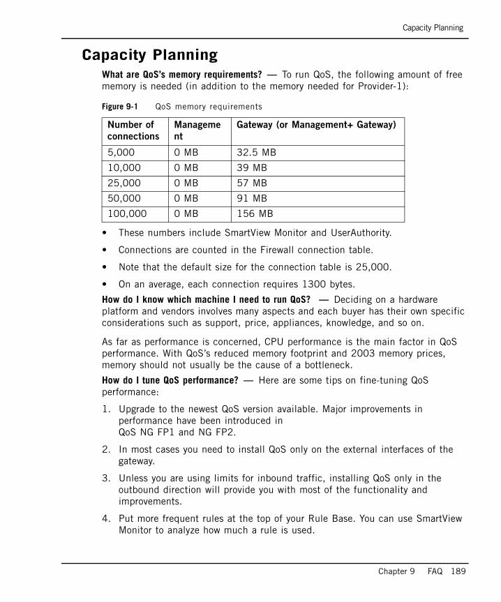
Capacity Planning
Chapter 9 FAQ 189
Capacity PlanningWhat are QoS’s memory requirements? — To run QoS, the following amount of free memory is needed (in addition to the memory needed for Provider-1):
• These numbers include SmartView Monitor and UserAuthority.
• Connections are counted in the Firewall connection table.
• Note that the default size for the connection table is 25,000.
• On an average, each connection requires 1300 bytes.
How do I know which machine I need to run QoS? — Deciding on a hardware platform and vendors involves many aspects and each buyer has their own specific considerations such as support, price, appliances, knowledge, and so on.
As far as performance is concerned, CPU performance is the main factor in QoS performance. With QoS’s reduced memory footprint and 2003 memory prices, memory should not usually be the cause of a bottleneck.
How do I tune QoS performance? — Here are some tips on fine-tuning QoS performance:
1. Upgrade to the newest QoS version available. Major improvements in performance have been introduced in QoS NG FP1 and NG FP2.
2. In most cases you need to install QoS only on the external interfaces of the gateway.
3. Unless you are using limits for inbound traffic, installing QoS only in the outbound direction will provide you with most of the functionality and improvements.
4. Put more frequent rules at the top of your Rule Base. You can use SmartView Monitor to analyze how much a rule is used.
Figure 9-1 QoS memory requirements
Number of
connections
Manageme
nt
Gateway (or Management+ Gateway)
5,000 0 MB 32.5 MB
10,000 0 MB 39 MB
25,000 0 MB 57 MB
50,000 0 MB 91 MB
100,000 0 MB 156 MB
Protocol Support
190
5. Turn “per connection limits” into “per rule limits”.
6. Turn “per connection guarantees” into “per rule guarantees”.
What is the maximum bandwidth supported by QoS? — QoS NG FP1 can support up to 1.13MBps and 890MBps (in Traditional Mode) of traffic of long UDP packets. In real-world traffic and in the Rule Base, QoS supports 330MBps (In Express Mode) and 255 MBps (in Traditional Mode) of traffic.
Protocol SupportWhat protocols/services are supported by QoS? — See: http://www.checkpoint.com/products/downloads/vpn-1_fw-1_fg-1_app_support.pdf
Can I prioritize system administration traffic? — Yes. This can be done in any of the following ways:
• Guarantees for administrators based on authentication
• Guarantees for administrators based on IPs, networks
• Guarantees for applications only administrators use (for example, Provider-1 control protocols, PC-Anywhere)
• Combinations of all the above
Does QoS support Citrix applications? — Yes, Citrix applications can be differentiated from one another. In addition, QoS can identify Citrix ICA printing traffic and re-classify it to a proper rule.
Does QoS support SIP? — Yes. Starting from QoS FP2, the SIP protocol is supported.
Does QoS support H323? — Yes. Starting from QoS FP1, the H323 protocol is supported
Does QoS support GRE? — Yes. This protocol is supported.
Installation/Backward Compatibility/Licensing/Versions
When will QoS next feature pack be available? — QoS feature packs/releases are usually shipped at the same time Provider-1 feature packs are released.
Note - New services and applications are added on a permanent basis.
How do I?
Chapter 9 FAQ 191
How do I?How do I guarantee performance for my mail server? — You need to add a rule matching your email traffic. You can do this by either matching the source/destination of your mail server, or matching mail protocols (SMTP, POP3, Exchange). For this rule, define a weight or guarantee that meets the needs of the priorities you want to set.
How do I ensure Quality of Service for Voice Over IP? — QoS FP1 introduced the VoIP-tuned mechanism Low Latency Queuing (LLQ). This mechanism is tuned to achieve best latency for constant bit rate applications, like VoIP.
To limit the number of connections admitted, use LLQ with a per connection guarantee. For voice, you want to give each conversation a guaranteed bandwidth. Usually you would want an admission policy that does not accept additional calls if bandwidth is not adequate.
How can I prioritize traffic for remote users? — Using the Authenticated QoS feature of QoS, you can prioritize bandwidth allocation for remote VPN users and Windows domain user groups. To configure the Windows domain users please refer to the UserAuthority Administration Guide and read the SecureAgent -> System Setup section.
How do I guarantee performance for my ERP applications? — You need to add a rule matching your ERP traffic. You can do this by either matching the source/destination of your ERP server, or matching application protocols (SAP, BAAN, ORACLE). For this rule, define a weight or guarantee that meets the needs of the priorities you want to set. If your ERP application is not a predefined service, you can either add it manually or use the first method.
If you are using ERP over HTTP, check “How can I provide bandwidth for my intranet applications”?
Can I use QoS to prevent Denial of Service Attacks? — QoS’s main goal is not an Anti-Denial of Service tool. However, there are many situations in which QoS can be used to detect, monitor and prevent such attacks. Using SmartView Monitor and QoS you can perform detection and monitoring.
Prevention can be achieved in the following ways:
• by limiting applications that are known to be a part of DOS attacks (for example, ICMP, suspicious URLs).
• by providing guarantees for important traffic (for example, ERP, MAIL, VoIP).
Note - This is equivalent to the busy tone in old voice system.
General Issues
192
• by providing guaranteed bandwidth for authenticated users using Authenticated QoS. Authenticated users can be identified with digital signatures and can rely on VPN authentication and encryption. QoS guarantees that these users will get their bandwidth. The attacker cannot authenticate to the VPN and will not get bandwidth for the attack.
Why is limiting bandwidth for Napster better than blocking It? — Blocking "nonwork-related" applications might cause users to find a way to bypass blocking. Prioritizing bandwidth lets users continue with their activities without damaging critical business processes. Consider a university where the Internet connection is being used for peer-to-peer file downloads like Napster and Kazaa. Blocking these services completely may encourage the students find a smart way to bypass the block, which in turn might cause legal problems. QoS offers smarter solutions:
• Limiting the allocated bandwidth for such applications – this can be done with or without the students’ knowledge.
• Limiting the allocated bandwidth during daytime, and providing more bandwidth at night.
• Providing guarantees to important users (Professors, MIS) while allowing students to use the reminder of the bandwidth.
General IssuesMy machine is experiencing certain technical failures. What should I do? — Check the Web for updated release notes on known issues and limitations. Contact your vendor for further support.
I set up a guarantee/limit but in SmartView Monitor it seems to be broken? — If you are looking at very low traffic limit (for example, 1000 Bytes per second) at a high frequency (update every 2 seconds) it might look, as if the limit is broken since QoS does not fragment packets. If you lower the sampling frequency of SmartView Monitor (update every 8 seconds) you will see that limits are kept.
Can QoS prompt a user for authentication in order to use the Authenticated QoS feature? — No. In order to use Authenticated QoS, Provider-1 must perform an authentication session prior to the classification of the connection by QoS.
Can I deploy QoS on LAN environments? — Yes. You will need to position the hardware to support the network traffic you want to prioritize. QoS is best deployed in congestion points for network traffic.
General Issues
Chapter 9 FAQ 193
What happens if a line’s bandwidth (as defined in the QoS tab of the Interface Properties window) is less than its physical (“real”) bandwidth? — QoS will only allocate as much bandwidth as is defined in the Interface Properties window. Additional bandwidth will not be allocated regardless of the physical bandwidth of the interface.
What happens if a link bandwidth (of the link defined in QoS) is more than its physical (“real”) bandwidth? — QoS will attempt to transmit more than the physical bandwidth allows. This can cause random traffic drops in the next hop that result in the loss of critical packets.

General Issues
194
195
Chapter 10Deploying QoS
In This Chapter
Deploying QoS page 196
Sample Bandwidth Allocations page 198
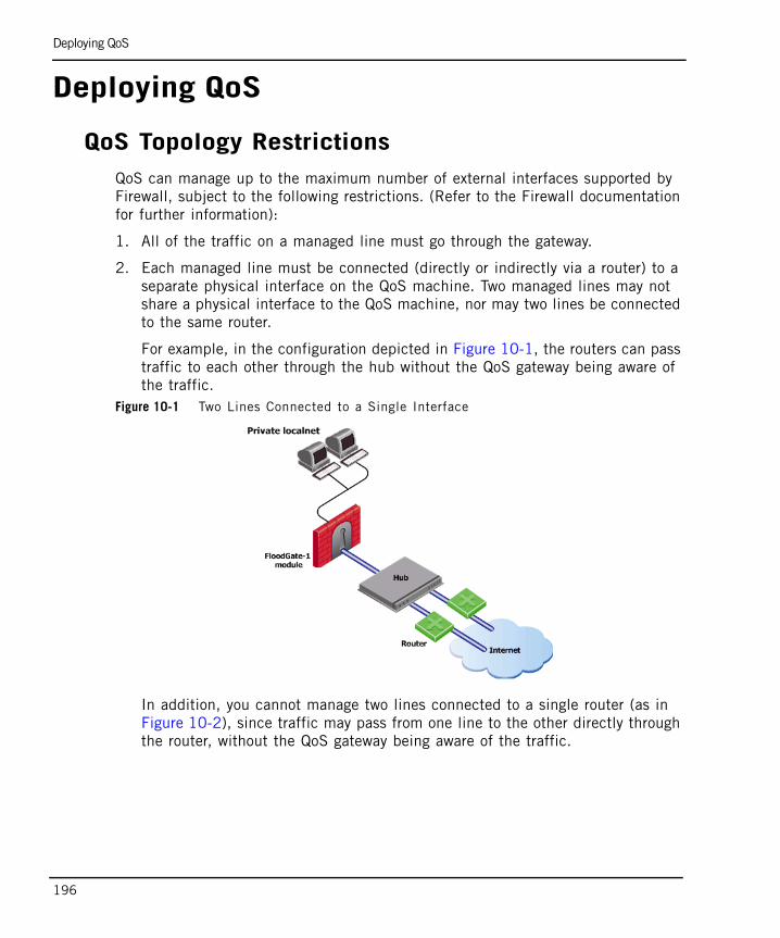
Deploying QoS
196
Deploying QoS
QoS Topology RestrictionsQoS can manage up to the maximum number of external interfaces supported by Firewall, subject to the following restrictions. (Refer to the Firewall documentation for further information):
1. All of the traffic on a managed line must go through the gateway.
2. Each managed line must be connected (directly or indirectly via a router) to a separate physical interface on the QoS machine. Two managed lines may not share a physical interface to the QoS machine, nor may two lines be connected to the same router.
For example, in the configuration depicted in Figure 10-1, the routers can pass traffic to each other through the hub without the QoS gateway being aware of the traffic.
Figure 10-1 Two Lines Connected to a Single Interface
In addition, you cannot manage two lines connected to a single router (as in Figure 10-2), since traffic may pass from one line to the other directly through the router, without the QoS gateway being aware of the traffic.
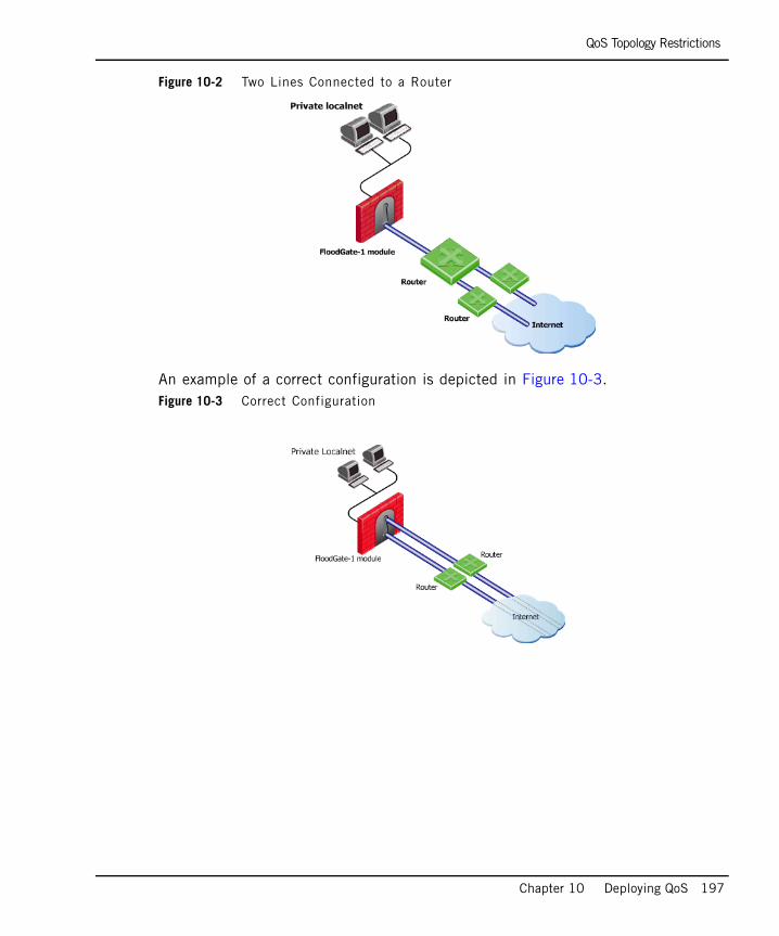
QoS Topology Restrictions
Chapter 10 Deploying QoS 197
Figure 10-2 Two Lines Connected to a Router
An example of a correct configuration is depicted in Figure 10-3.Figure 10-3 Correct Configuration
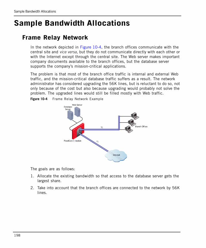
Sample Bandwidth Allocations
198
Sample Bandwidth Allocations
Frame Relay NetworkIn the network depicted in Figure 10-4, the branch offices communicate with the central site and vice versa, but they do not communicate directly with each other or with the Internet except through the central site. The Web server makes important company documents available to the branch offices, but the database server supports the company’s mission-critical applications.
The problem is that most of the branch office traffic is internal and external Web traffic, and the mission-critical database traffic suffers as a result. The network administrator has considered upgrading the 56K lines, but is reluctant to do so, not only because of the cost but also because upgrading would probably not solve the problem. The upgraded lines would still be filled mostly with Web traffic.Figure 10-4 Frame Relay Network Example
The goals are as follows:
1. Allocate the existing bandwidth so that access to the database server gets the largest share.
2. Take into account that the branch offices are connected to the network by 56K lines.
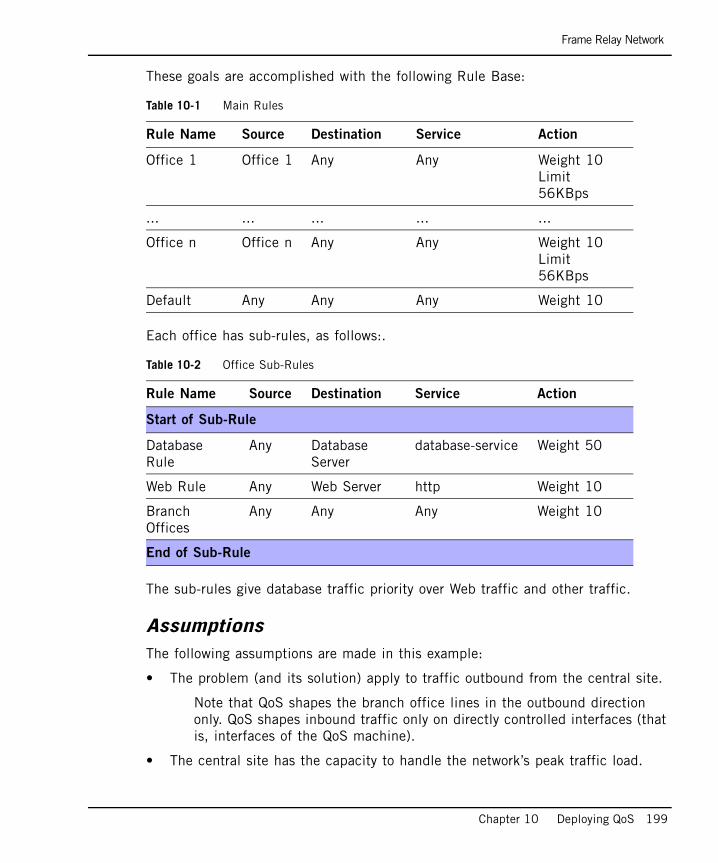
Frame Relay Network
Chapter 10 Deploying QoS 199
These goals are accomplished with the following Rule Base:
Each office has sub-rules, as follows:.
The sub-rules give database traffic priority over Web traffic and other traffic.
AssumptionsThe following assumptions are made in this example:
• The problem (and its solution) apply to traffic outbound from the central site.
Note that QoS shapes the branch office lines in the outbound direction only. QoS shapes inbound traffic only on directly controlled interfaces (that is, interfaces of the QoS machine).
• The central site has the capacity to handle the network’s peak traffic load.
Table 10-1 Main Rules
Rule Name Source Destination Service Action
Office 1 Office 1 Any Any Weight 10Limit 56KBps
... ... ... ... ...
Office n Office n Any Any Weight 10Limit 56KBps
Default Any Any Any Weight 10
Table 10-2 Office Sub-Rules
Rule Name Source Destination Service Action
Start of Sub-Rule
Database Rule
Any Database Server
database-service Weight 50
Web Rule Any Web Server http Weight 10
Branch Offices
Any Any Any Weight 10
End of Sub-Rule
Frame Relay Network
200
• There is no traffic between the offices.
201
Appendix ADebug Flags
Note - Error is turned on by default.
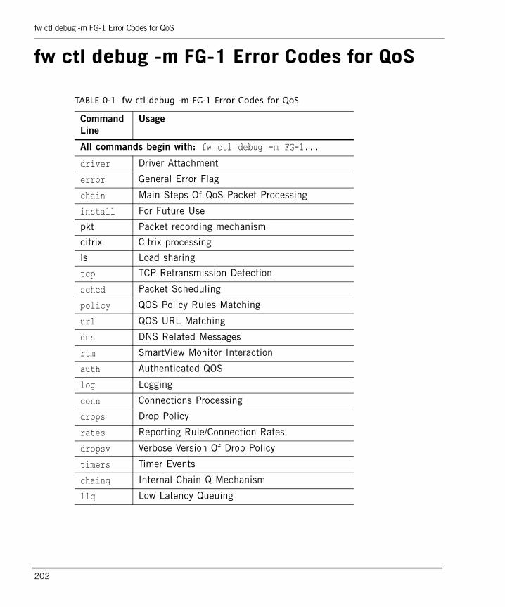
fw ctl debug -m FG-1 Error Codes for QoS
202
fw ctl debug -m FG-1 Error Codes for QoS
TABLE 0-1 fw ctl debug -m FG-1 Error Codes for QoS
Command
Line
Usage
All commands begin with: fw ctl debug -m FG-1...
driver Driver Attachment
error General Error Flag
chain Main Steps Of QoS Packet Processing
install For Future Use
pkt Packet recording mechanism
citrix Citrix processing
ls Load sharing
tcp TCP Retransmission Detection
sched Packet Scheduling
policy QOS Policy Rules Matching
url QOS URL Matching
dns DNS Related Messages
rtm SmartView Monitor Interaction
auth Authenticated QOS
log Logging
conn Connections Processing
drops Drop Policy
rates Reporting Rule/Connection Rates
dropsv Verbose Version Of Drop Policy
timers Timer Events
chainq Internal Chain Q Mechanism
llq Low Latency Queuing
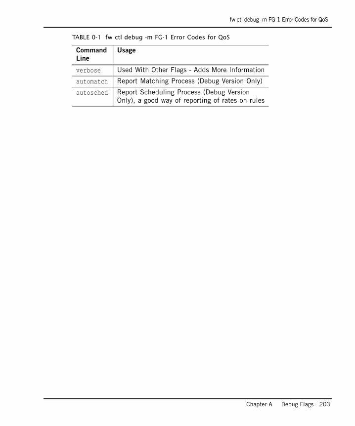
fw ctl debug -m FG-1 Error Codes for QoS
Chapter A Debug Flags 203
verbose Used With Other Flags - Adds More Information
automatch Report Matching Process (Debug Version Only)
autosched Report Scheduling Process (Debug Version Only), a good way of reporting of rates on rules
TABLE 0-1 fw ctl debug -m FG-1 Error Codes for QoS
Command
Line
Usage

fw ctl debug -m FG-1 Error Codes for QoS
204