Embed Size (px)
Citation preview
CHEM 3452 QUANTITATIVE TECHNIQUES
Student Name:
__________________________
Faraday’s Law: Electrodeposition Of Nickel
Motivation
Electroplating is an important branch of electrochemistry with many applications in modern
technological developments. For example, the automobile industry relies on nickel and chromium
electroplating to protect steel from corrosion. The decorative plating sector uses noble metal electroplating
to produce attractive jewelry. Also, electroplating constitutes an essential fabrication tool for producing
state of the art electronics. Since 1997, electrodeposited Cu metal interconnects within integrated circuit
microchips has been the information superhighway that facilitates our daily digital communication. In this
lab, we will use a disposable screen-printed electrode to study the metal deposition process on electrode
surfaces. You will learn the following techniques and concepts by performing this new lab experiment:
1. reduction/oxidation processes
2. integrated patterned electrode
3. electroplating
4. electrochemical cell and electrolyte
5. controlling the extent of chemical reaction by the electrical current flow
6. learning the Faraday’s Law
7. calculating overall electroplating efficiency
Experimental Procedures
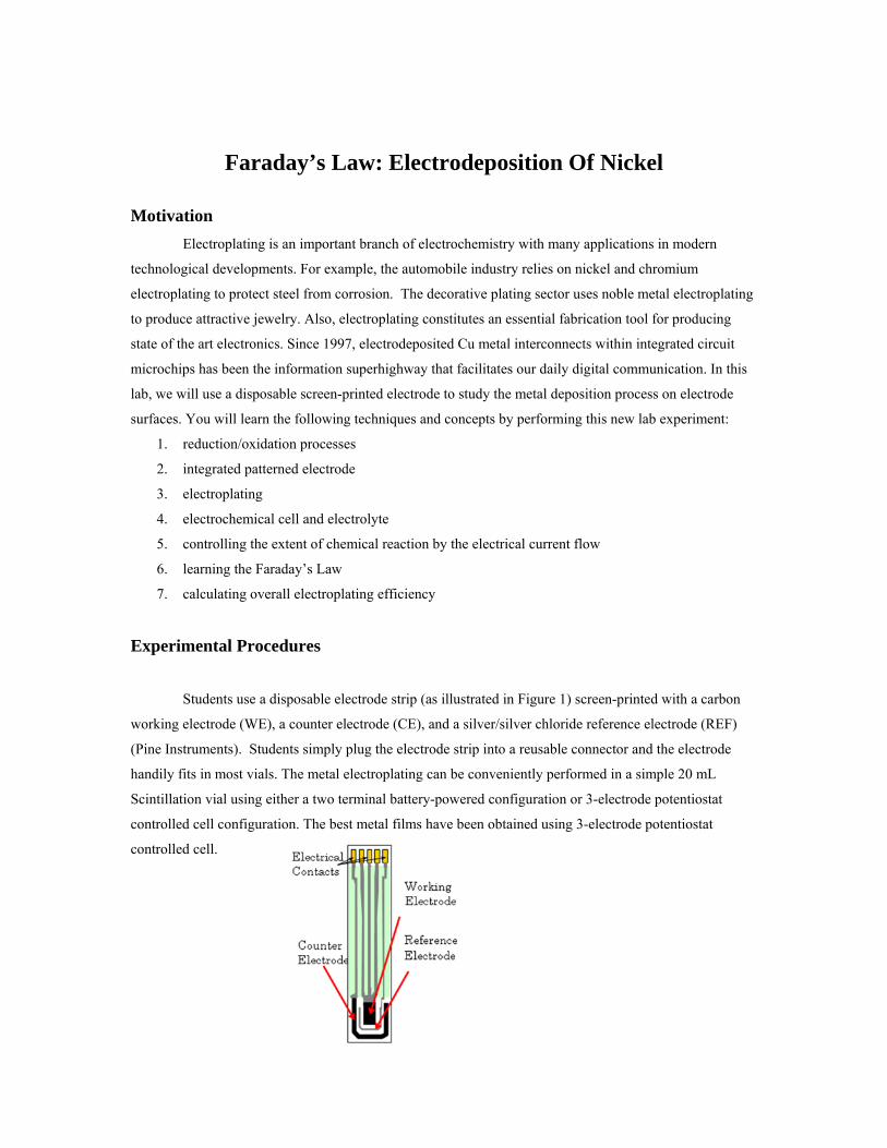
Students use a disposable electrode strip (as illustrated in Figure 1) screen-printed with a carbon
working electrode (WE), a counter electrode (CE), and a silver/silver chloride reference electrode (REF)
(Pine Instruments). Students simply plug the electrode strip into a reusable connector and the electrode
handily fits in most vials. The metal electroplating can be conveniently performed in a simple 20 mL
Scintillation vial using either a two terminal battery-powered configuration or 3-electrode potentiostat
controlled cell configuration. The best metal films have been obtained using 3-electrode potentiostat
controlled cell.
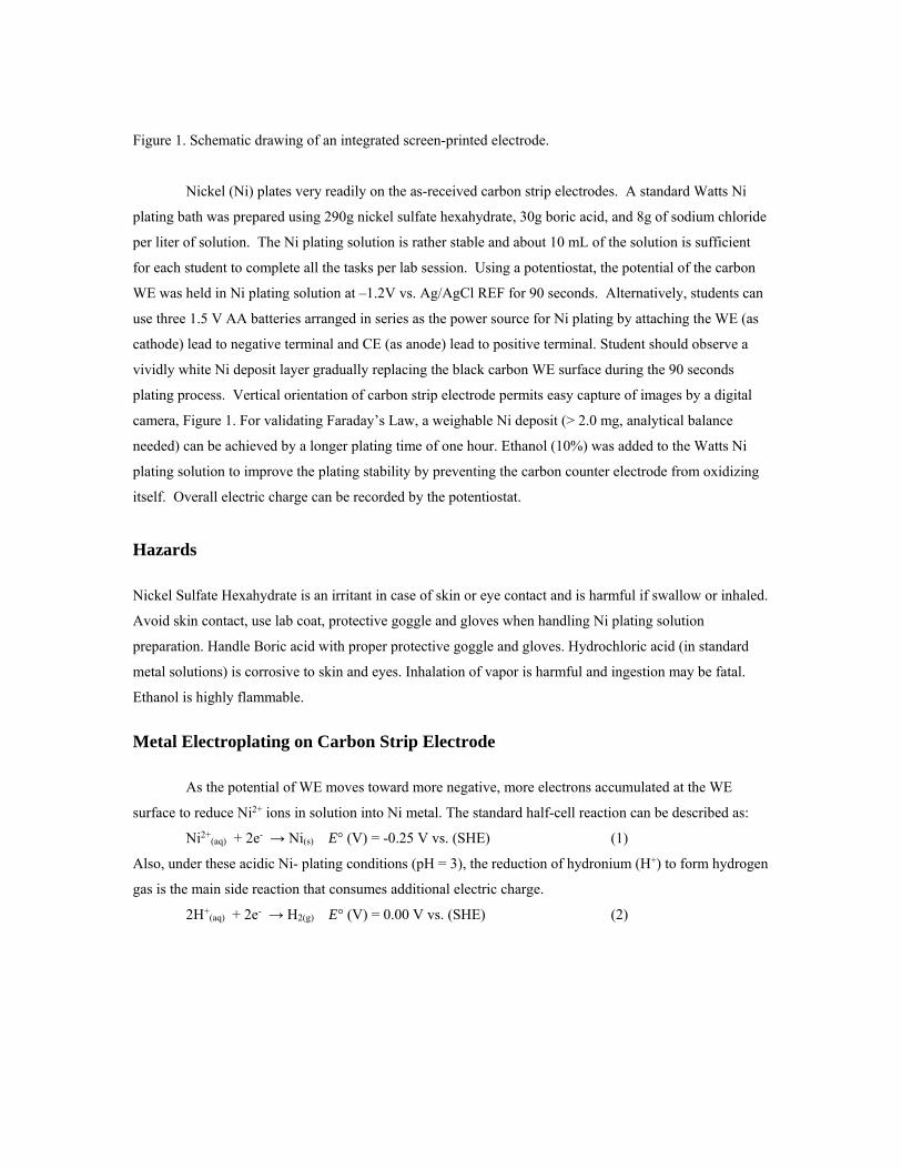
Figure 1. Schematic drawing of an integrated screen-printed electrode.
Nickel (Ni) plates very readily on the as-received carbon strip electrodes. A standard Watts Ni
plating bath was prepared using 290g nickel sulfate hexahydrate, 30g boric acid, and 8g of sodium chloride
per liter of solution. The Ni plating solution is rather stable and about 10 mL of the solution is sufficient
for each student to complete all the tasks per lab session. Using a potentiostat, the potential of the carbon
WE was held in Ni plating solution at –1.2V vs. Ag/AgCl REF for 90 seconds. Alternatively, students can
use three 1.5 V AA batteries arranged in series as the power source for Ni plating by attaching the WE (as
cathode) lead to negative terminal and CE (as anode) lead to positive terminal. Student should observe a
vividly white Ni deposit layer gradually replacing the black carbon WE surface during the 90 seconds
plating process. Vertical orientation of carbon strip electrode permits easy capture of images by a digital
camera, Figure 1. For validating Faraday’s Law, a weighable Ni deposit (> 2.0 mg, analytical balance
needed) can be achieved by a longer plating time of one hour. Ethanol (10%) was added to the Watts Ni
plating solution to improve the plating stability by preventing the carbon counter electrode from oxidizing
itself. Overall electric charge can be recorded by the potentiostat.
Hazards
Nickel Sulfate Hexahydrate is an irritant in case of skin or eye contact and is harmful if swallow or inhaled.
Avoid skin contact, use lab coat, protective goggle and gloves when handling Ni plating solution
preparation. Handle Boric acid with proper protective goggle and gloves. Hydrochloric acid (in standard
metal solutions) is corrosive to skin and eyes. Inhalation of vapor is harmful and ingestion may be fatal.
Ethanol is highly flammable.
Metal Electroplating on Carbon Strip Electrode
As the potential of WE moves toward more negative, more electrons accumulated at the WE
surface to reduce Ni2+ ions in solution into Ni metal. The standard half-cell reaction can be described as:
Ni2+(aq) + 2e- → Ni(s) E° (V) = -0.25 V vs. (SHE) (1)
Also, under these acidic Ni- plating conditions (pH = 3), the reduction of hydronium (H+) to form hydrogen
gas is the main side reaction that consumes additional electric charge.
2H+(aq) + 2e- → H2(g) E° (V) = 0.00 V vs. (SHE) (2)
Learning Faraday’s Law
Faraday’s law states that the amount of chemical reaction (i.e. mass of
electroplating metal, W) caused by the flow of current is proportional to the amount of
electric charge (Q) passed through the electrochemical cell.
W = ZQ (3)
Z is the constant of proportionality called the electrochemical equivalent. Z can be
expressed as
Z = Awt / nF (4)
where Awt, is the atomic weight of metal deposited on cathode (for Ni, 58.69 g / mol); n,
is the number of electrons involved in the deposition reaction (for Ni2+ to Ni, n = 2); F, is
the Faraday’s constant = 9.6485 x 10⁴ C/mol, named after Michael Faraday (1791-1867)
who formulated the quantitative relationship between electrical current and the extent of
chemical reaction in electrochemical cell. Therefore, the electrochemical equivalent Z of
Ni for the case of electroplating of Ni from Ni2+ solution is,
Z = Awt / nF = 58.69 / 2 x 96485 = 3.041 x 10⁻⁴ gC-1 (5)
It states that consumption of one coulomb (C) electric charge can electrodeposit a
maximum of 3.041 x 10⁻⁴ g Ni on cathode. As shown later, other side reactions often
reduce the overall electroplating current efficiency below 100%. Finally, the combination
of Eqs. (3) and (4) yields
W = (Awt / nF ) Q (6)
The actual Ni plating efficiency is always less than 100% due to the side reactions that
consuming additional electric charge.
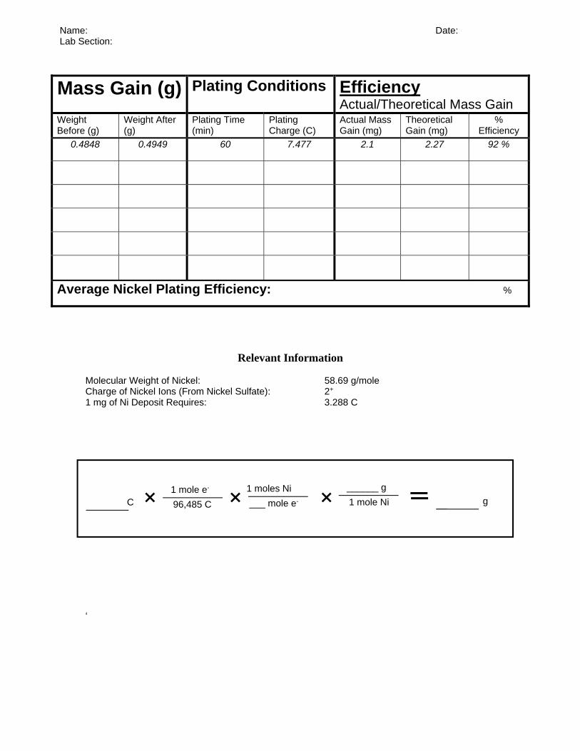
Relevant Information Molecular Weight of Nickel: 58.69 g/mole Charge of Nickel Ions (From Nickel Sulfate): 2+
1 mg of Ni Deposit Requires: 3.288 C
‘
Mass Gain (g) Plating Conditions Efficiency Actual/Theoretical Mass Gain
Weight Before (g)
Weight After (g)
Plating Time (min)
Plating Charge (C)
Actual Mass Gain (mg)
Theoretical Gain (mg)
% Efficiency
0.4848 0.4949 60 7.477 2.1 2.27 92 %
Average Nickel Plating Efficiency: %
C 96,485 C
1 mole e-
___ mole e-
1 moles Ni
1 mole Ni
______ g
g
Name: Date: Lab Section:
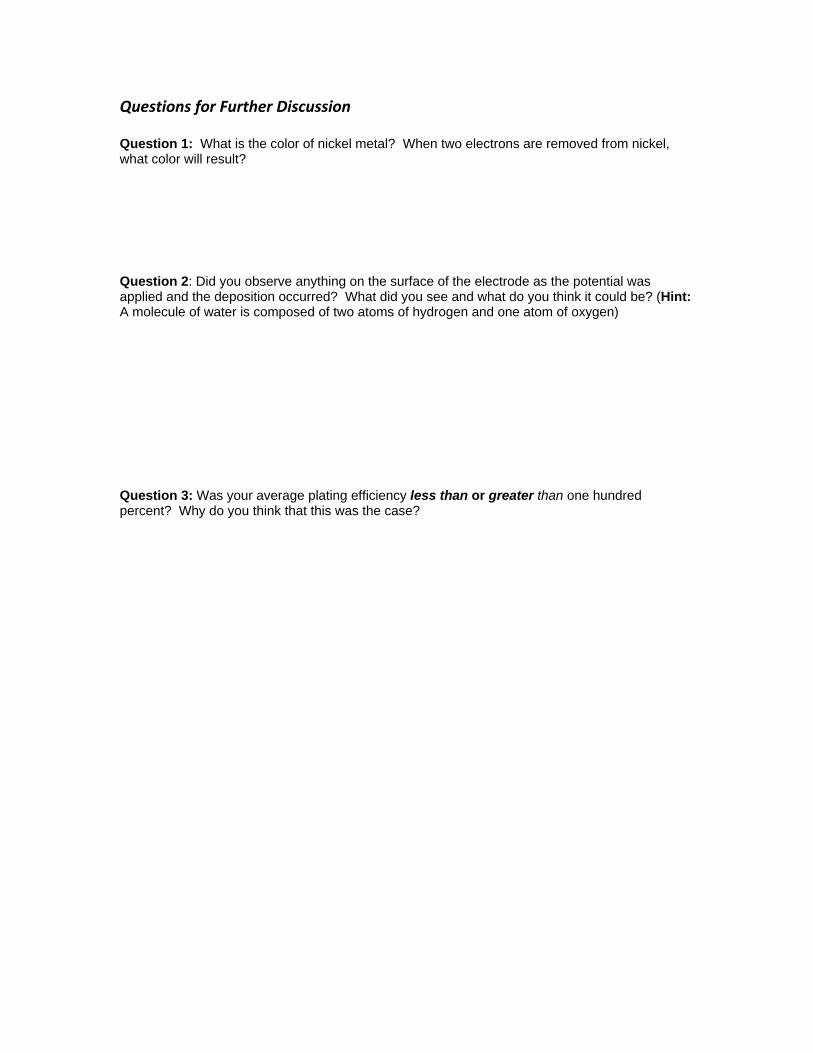
Questions for Further Discussion Question 1: What is the color of nickel metal? When two electrons are removed from nickel, what color will result? Question 2: Did you observe anything on the surface of the electrode as the potential was applied and the deposition occurred? What did you see and what do you think it could be? (Hint: A molecule of water is composed of two atoms of hydrogen and one atom of oxygen) Question 3: Was your average plating efficiency less than or greater than one hundred percent? Why do you think that this was the case?
Operation Instruction for WaveNow Potentiostat
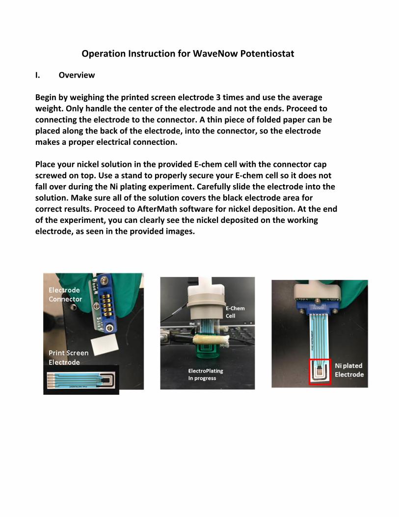
I. Overview
Begin by weighing the printed screen electrode 3 times and use the average weight. Only handle the center of the electrode and not the ends. Proceed to connecting the electrode to the connector. A thin piece of folded paper can be placed along the back of the electrode, into the connector, so the electrode makes a proper electrical connection.
Place your nickel solution in the provided E‐chem cell with the connector cap screwed on top. Use a stand to properly secure your E‐chem cell so it does not fall over during the Ni plating experiment. Carefully slide the electrode into the solution. Make sure all of the solution covers the black electrode area for correct results. Proceed to AfterMath software for nickel deposition. At the end of the experiment, you can clearly see the nickel deposited on the working electrode, as seen in the provided images.
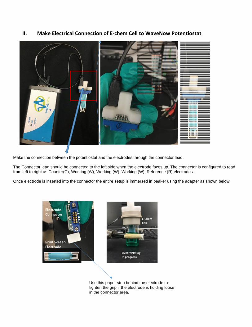
II. Make Electrical Connection of E‐chem Cell to WaveNow Potentiostat
Use this paper strip behind the electrode to tighten the grip if the electrode is holding loose in the connector area.
Make the connection between the potentiostat and the electrodes through the connector lead. The Connector lead should be connected to the left side when the electrode faces up. The connector is configured to read from left to right as Counter(C), Working (W), Working (W), Working (W), Reference (R) electrodes. Once electrode is inserted into the connector the entire setup is immersed in beaker using the adapter as shown below.
CWWWR
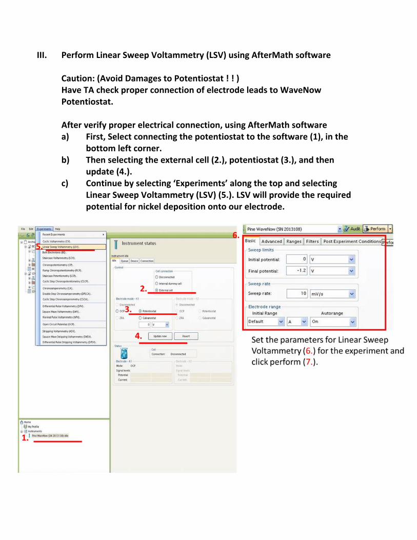
III. Perform Linear Sweep Voltammetry (LSV) using AfterMath software Caution: (Avoid Damages to Potentiostat ! ! ) Have TA check proper connection of electrode leads to WaveNow Potentiostat. After verify proper electrical connection, using AfterMath software a) First, Select connecting the potentiostat to the software (1), in the
bottom left corner. b) Then selecting the external cell (2.), potentiostat (3.), and then
update (4.). c) Continue by selecting ‘Experiments’ along the top and selecting
Linear Sweep Voltammetry (LSV) (5.). LSV will provide the required potential for nickel deposition onto our electrode.
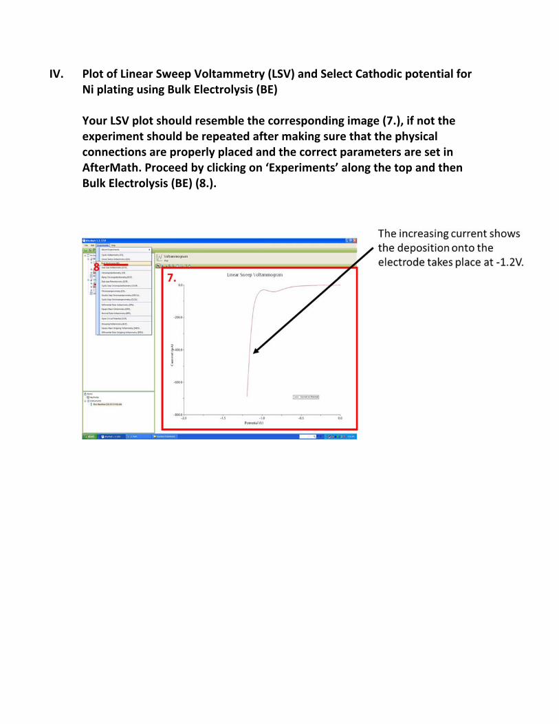
IV. Plot of Linear Sweep Voltammetry (LSV) and Select Cathodic potential for Ni plating using Bulk Electrolysis (BE) Your LSV plot should resemble the corresponding image (7.), if not the experiment should be repeated after making sure that the physical connections are properly placed and the correct parameters are set in AfterMath. Proceed by clicking on ‘Experiments’ along the top and then Bulk Electrolysis (BE) (8.).
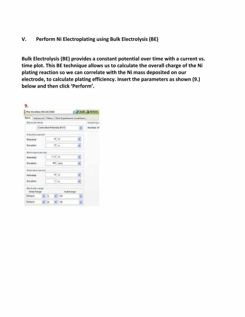
V. Perform Ni Electroplating using Bulk Electrolysis (BE)
Bulk Electrolysis (BE) provides a constant potential over time with a current vs. time plot. This BE technique allows us to calculate the overall charge of the Ni plating reaction so we can correlate with the Ni mass deposited on our electrode, to calculate plating efficiency. Insert the parameters as shown (9.) below and then click ‘Perform’.
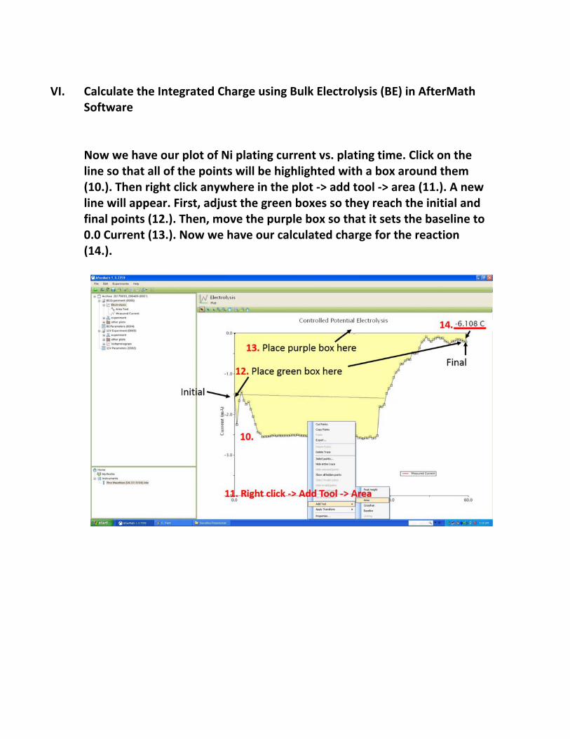
VI. Calculate the Integrated Charge using Bulk Electrolysis (BE) in AfterMath
Software Now we have our plot of Ni plating current vs. plating time. Click on the line so that all of the points will be highlighted with a box around them (10.). Then right click anywhere in the plot ‐> add tool ‐> area (11.). A new line will appear. First, adjust the green boxes so they reach the initial and final points (12.). Then, move the purple box so that it sets the baseline to 0.0 Current (13.). Now we have our calculated charge for the reaction (14.).