Embed Size (px)
Citation preview
chemfigv1.41
21 may 2019
Christian Tellechea
A TEX package for drawing molecules
OO
NH
OH
O
O
HO
CH3
CH3
OH O
CH3
OH
O
O
CH3
O
O
O
CH3
Taxotere
R′ R
NOH
H⊕
R′ R
N
⊕OH2
−H2O
R′
⊕N C R
R′ N⊕C R
H2O
R′
N R
⊕OH2
−H⊕
R′
N R
OH
R′
NH
R
O
The Beckmann rearrangement
Contents
I Introduction 4
1 New in v1.4 41.1 Primitive \expanded . . . . . . . . . . . . . . . . . . . . . . . . . . . . . . . . . . . . . . . . . . . . 4
1.2 Position and rotation of delimiters . . . . . . . . . . . . . . . . . . . . . . . . . . . . . . . . . . . . 4
1.3 Private char . . . . . . . . . . . . . . . . . . . . . . . . . . . . . . . . . . . . . . . . . . . . . . . . 4
1.4 Char # . . . . . . . . . . . . . . . . . . . . . . . . . . . . . . . . . . . . . . . . . . . . . . . . . . . 4
1.5 Old macros and new syntax . . . . . . . . . . . . . . . . . . . . . . . . . . . . . . . . . . . . . . . 5
1.6 Macros \lewis and \Lewis . . . . . . . . . . . . . . . . . . . . . . . . . . . . . . . . . . . . . . . . 5
2 Presenting chemfig 5
3 Acknowledgment 6
II Operation of chemfig 7
1 The \chemfig macro 7
2 Groups of atoms 8
3 Di�erent types of bonds 8
4 Bond angle 104.1 Prede�ned angles . . . . . . . . . . . . . . . . . . . . . . . . . . . . . . . . . . . . . . . . . . . . . 10
4.2 Absolute angles . . . . . . . . . . . . . . . . . . . . . . . . . . . . . . . . . . . . . . . . . . . . . . 10
4.3 Relative angles . . . . . . . . . . . . . . . . . . . . . . . . . . . . . . . . . . . . . . . . . . . . . . . 11
5 Length of a bond 11
6 Departure and arrival atoms 12
7 Customization of bonds 13
8 Default values 13
9 Branches 149.1 Principle . . . . . . . . . . . . . . . . . . . . . . . . . . . . . . . . . . . . . . . . . . . . . . . . . . 14
9.2 Nesting . . . . . . . . . . . . . . . . . . . . . . . . . . . . . . . . . . . . . . . . . . . . . . . . . . . 15
9.3 Method . . . . . . . . . . . . . . . . . . . . . . . . . . . . . . . . . . . . . . . . . . . . . . . . . . . 15
10 Connecting distant atoms 16
11 Rings 1711.1 Syntax . . . . . . . . . . . . . . . . . . . . . . . . . . . . . . . . . . . . . . . . . . . . . . . . . . . 17
11.2 Angular position . . . . . . . . . . . . . . . . . . . . . . . . . . . . . . . . . . . . . . . . . . . . . . 18
11.2.1 At the start . . . . . . . . . . . . . . . . . . . . . . . . . . . . . . . . . . . . . . . . . . . . 18
11.2.2 After a bond . . . . . . . . . . . . . . . . . . . . . . . . . . . . . . . . . . . . . . . . . . . . 19
11.3 Branches on a ring . . . . . . . . . . . . . . . . . . . . . . . . . . . . . . . . . . . . . . . . . . . . . 19
11.4 Nested rings . . . . . . . . . . . . . . . . . . . . . . . . . . . . . . . . . . . . . . . . . . . . . . . . 20
11.5 Rings and groups of atoms . . . . . . . . . . . . . . . . . . . . . . . . . . . . . . . . . . . . . . . . 21
12 Representing electron movements 2112.1 Mesomeric e�ects . . . . . . . . . . . . . . . . . . . . . . . . . . . . . . . . . . . . . . . . . . . . . 22
12.2 Reaction mechanisms . . . . . . . . . . . . . . . . . . . . . . . . . . . . . . . . . . . . . . . . . . . 24
13 Writing a name under a molecule 24
Compiled the May 21, 2019. 1
III Advanced usage 26
1 Separating atoms 26
2 Displaying atoms 26
3 Arguments given to tikz 27
4 Vertical alignment 27
5 Shifted double bonds 29
6 Delocalized double bonds 30
7 Saving a sub-molecule 30
8 Decorations 328.1 Lewis diagrams . . . . . . . . . . . . . . . . . . . . . . . . . . . . . . . . . . . . . . . . . . . . . . 32
8.2 Stacking characters . . . . . . . . . . . . . . . . . . . . . . . . . . . . . . . . . . . . . . . . . . . . 34
9 Using \chemfig in the tikzpicture environment 34
10 Beyond chemistry 34
11 Annotated examples 3611.1 Ethanal . . . . . . . . . . . . . . . . . . . . . . . . . . . . . . . . . . . . . . . . . . . . . . . . . . . 36
11.2 2-amino-4-oxohexanoic acid . . . . . . . . . . . . . . . . . . . . . . . . . . . . . . . . . . . . . . . 36
11.2.1 Absolute angles . . . . . . . . . . . . . . . . . . . . . . . . . . . . . . . . . . . . . . . . . . 36
11.2.2 Relative angles . . . . . . . . . . . . . . . . . . . . . . . . . . . . . . . . . . . . . . . . . . 37
11.2.3 Ring . . . . . . . . . . . . . . . . . . . . . . . . . . . . . . . . . . . . . . . . . . . . . . . . 37
11.2.4 Nested rings . . . . . . . . . . . . . . . . . . . . . . . . . . . . . . . . . . . . . . . . . . . . 37
11.3 Glucose . . . . . . . . . . . . . . . . . . . . . . . . . . . . . . . . . . . . . . . . . . . . . . . . . . . 38
11.3.1 Skeleton diagram . . . . . . . . . . . . . . . . . . . . . . . . . . . . . . . . . . . . . . . . . 38
11.3.2 Fisher projection . . . . . . . . . . . . . . . . . . . . . . . . . . . . . . . . . . . . . . . . . 38
11.3.3 “Chair” representation . . . . . . . . . . . . . . . . . . . . . . . . . . . . . . . . . . . . . . 40
11.3.4 Haworth projection . . . . . . . . . . . . . . . . . . . . . . . . . . . . . . . . . . . . . . . . 40
11.4 Adrenaline . . . . . . . . . . . . . . . . . . . . . . . . . . . . . . . . . . . . . . . . . . . . . . . . . 41
11.4.1 Using one ring . . . . . . . . . . . . . . . . . . . . . . . . . . . . . . . . . . . . . . . . . . 41
11.4.2 Using two rings . . . . . . . . . . . . . . . . . . . . . . . . . . . . . . . . . . . . . . . . . . 41
11.5 Guanine . . . . . . . . . . . . . . . . . . . . . . . . . . . . . . . . . . . . . . . . . . . . . . . . . . 42
12 How to . . . 4312.1 Write a colored atom . . . . . . . . . . . . . . . . . . . . . . . . . . . . . . . . . . . . . . . . . . . 43
12.2 Add a superscript without modifying a bond . . . . . . . . . . . . . . . . . . . . . . . . . . . . . . 44
12.3 Draw a curve bond . . . . . . . . . . . . . . . . . . . . . . . . . . . . . . . . . . . . . . . . . . . . 45
12.4 Draw a ploymer element . . . . . . . . . . . . . . . . . . . . . . . . . . . . . . . . . . . . . . . . . 45
12.5 Draw the symmetrical of a molecule . . . . . . . . . . . . . . . . . . . . . . . . . . . . . . . . . . . 47
12.6 Add text above bonds and arc to angles . . . . . . . . . . . . . . . . . . . . . . . . . . . . . . . . . 47
12.7 Schéma de Lewis à l’angle près . . . . . . . . . . . . . . . . . . . . . . . . . . . . . . . . . . . . . . 48
12.8 Dessiner des liaisons multiples . . . . . . . . . . . . . . . . . . . . . . . . . . . . . . . . . . . . . . 49
IV Reaction schemes 49
1 Overview 49
2 Arrow types 50
3 Arrows features 50
4 Compounds names 51
Compiled the May 21, 2019. 2
5 Anchoring 52
6 Compounds style 53
7 Branching 54
8 Subscheme 55
9 Arrows optional arguments 57
10 Arrows customization 5910.1 First arrow . . . . . . . . . . . . . . . . . . . . . . . . . . . . . . . . . . . . . . . . . . . . . . . . . 60
10.2 Curved arrow . . . . . . . . . . . . . . . . . . . . . . . . . . . . . . . . . . . . . . . . . . . . . . . 61
11 The \merge command 62
12 The + sign 64
V List of commands 66
VI Gallery 68
Compiled the May 21, 2019. 3
Introduction
1 New in v1.4
1.1 Primitive \expanded
Important: As of version 1.41, chemfig requires a TEX engine that provides the \expanded primitive. If this
is not available, an error message will be issued and version 1.4 will be loaded (last version working without
the primitive \expanded); it is strongly recommended that you update your LATEX distribution in order to take
advantage of the newer TEX engines that provide for the use of this new primitive.
1.2 Position and rotation of delimiters
The new key h align for delimiters allows, when set to ⟨false⟩, to no longer automatically align delimiters
horizontally. When the delimiters are no longer on the same horizontal, they can be rotated automatically by
setting the key auto rotate to ⟨true⟩. You can override this automatic setting and choose the rotation angle with
the key rotate. See page 45.
1.3 Private char
In the code of chemfig, the character used in the name of private macros is "_" (underscore) and no longer "@"
(arobe): the pre�x of private macros of chemfig is "\CF_". The majority of chemfig users should not be a�ected
by this change, but the development or maintenance of speci�c codes such as those presented in the "Arrow
customization" section on page 59 which uses private macros should take this catcode change into account; this
will require an update of macros names for those who have used private macros from chemfig. To allow "_" in macro
names, we must execute the order "\catcode‘\_=11" and then, to return to a normal state run "\catcode‘\_=8".
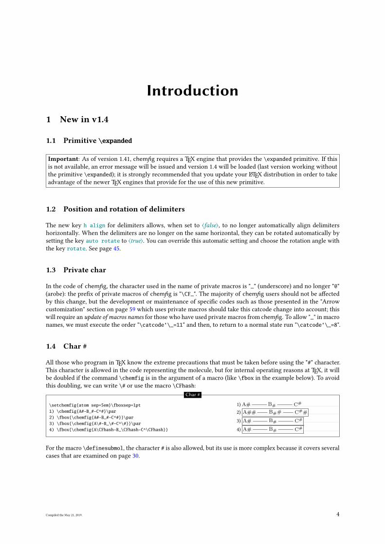
1.4 Char #
All those who program in TEX know the extreme precautions that must be taken before using the "#" character.
This character is allowed in the code representing the molecule, but for internal operating reasons at TEX, it will
be doubled if the command \chemfig is in the argument of a macro (like \fbox in the example below). To avoid
this doubling, we can write \# or use the macro \CFhash:
\setchemfig{atom sep=5em}\fboxsep=1pt1) \chemfig{A#-B_#-C^#}\par2) \fbox{\chemfig{A#-B_#-C^#}}\par3) \fbox{\chemfig{A\#-B_\#-C^\#}}\par4) \fbox{\chemfig{A\CFhash-B_\CFhash-C^\CFhash}}
1) A# B# C#
2) A## B## C##
3) A# B# C#
4) A# B# C#
Char #
For the macro \definesubmol, the character # is also allowed, but its use is more complex because it covers several
cases that are examined on page 30.
Compiled the May 21, 2019. 4
1.5 Old macros and new syntax
Macros previously used to set the parameters of chemfig are abandoned, are no longer de�ned and therefore, willresult in a compilation error if they are executed:
\setcrambond \setatomsep \enablefixedbondlength\disablefixedbondlength \setbondoffset \setdoublesep\setangleincrement \setnodestyle \setbondstyle\setlewis \setlewisdist \setstacksep\setcompoundstyle \setarrowdefault \setandsign\setarrowoffset \setcompoundsep \setarrowlabelsep\enablebondjoin \disablebondjoin \schemedebug
Now, to set the parameters of chemfig we have the choice:
• the macro \setchemfig{〈keys〉=〈values〉} sets the parameters according to the key/value method for the
rest of the document;
• the macro \chemfig[〈keys〉=〈values〉] receives in its optional argument the parameters valid only for
this molecule;
• the macro \resetchemfig restores the parameters to their default values.
The complete list of parameters and their default values is shown page 7.
Starred syntax \chemfig* is no longer allowed. To specify a constant length of bonds, use the key fixed lengthand set it to ⟨true⟩, see page 8.
1.6 Macros \lewis and \Lewis
These two macros also have a slight syntax change. Their optional argument between brackets is no longer
intended to receive the diagonal spacing coe�cient, but 〈〈key〉=values〉 so that the parameters can be set for
each macro call. See page 32.
2 Presenting chemfig
To use this package, start by adding the following code to the preamble:
• \input chemfig.tex with εTEX;
• \usepackage{chemfig} with LATEX;
• \usemodule[chemfig] with ConTEXt*ConTeXt@ConTEXt.
In all cases, the tikz package, if not loaded before, is loaded by chemfig.
The most important command for drawing molecules is \chemfig{〈code〉}. The argument code is a set of
characters describing the structure of the molecule according to the rules which are described in this manual.
Care has been taken to make it possible to draw the greatest possible number of molecular con�gurations, while
maintaining a simple, �exible, and intuitive syntax. Despite this, the 〈code〉 which describes the 2D structure of
the molecule increases in complexity in proportion to that of the molecule being drawn.
The command \chemfig draws a molecule using the commands provided by the tikz package, placed inside a
tikzpicture environment. The choice of tikz implies that:
• the user has a choice of compilation method: pdfLATEX can be used equally well in dvi mode (tex −→dvi −→ ps −→ pdf) or in pdf mode (tex −→ pdf). In e�ect tikz, via the underlying pgf, gives identical
graphical results in the two modes;
• the bounding box is automatically calculated by tikz and the user need not worry about any overlap with
the text. However, care must be taken with alignment when the molecule is drawn in a paragraph. In the
following example, we have drawn the bounding box for the molecule: H3C C
OH
O
.
Compiled the May 21, 2019. 5

3 Acknowledgment
This package has seen the light of day thanks to the assistance of Christophe Casseau, who had the idea. I thank
him for his help before writing the code and for the tests he carried out.
I also want to warmly thank Theo Hopman for o�ering to translate this manual into English.
Compiled the May 21, 2019. 6
Operation of chemfigThis part is devoted to describing the most common features of chemfig. The user will �nd here explanations
su�cient to draw most molecules. The presentation of features is done from a theoretical angle, and the goal of
this part is not to draw real molecules but to give the user a formal description of the functionality of chemfig. The
“Advanced usage”, page 26, will be more practical and will illustrate advanced features for the most demanding
uses. It will also highlight methods of building real molecules, page 36. Finally, the last part will give examples of
molecules and the code used to draw them.
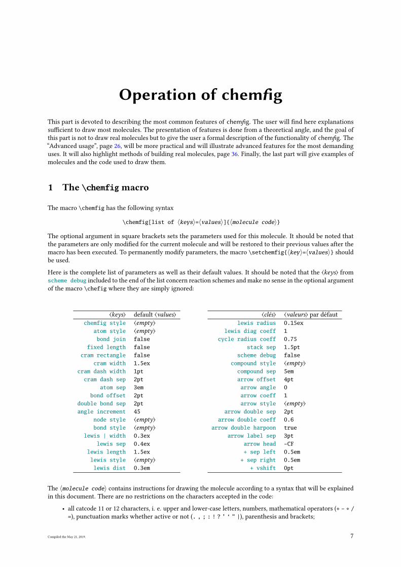
1 The \chemfig macro
The macro \chemfig has the following syntax
\chemfig[list of 〈keys〉=〈values〉]{〈molecule code〉}
The optional argument in square brackets sets the parameters used for this molecule. It should be noted that
the parameters are only modi�ed for the current molecule and will be restored to their previous values after the
macro has been executed. To permanently modify parameters, the macro \setchemfig{〈key〉=〈values〉} should
be used.
Here is the complete list of parameters as well as their default values. It should be noted that the ⟨keys⟩ from
scheme debug included to the end of the list concern reaction schemes and make no sense in the optional argument
of the macro \chefig where they are simply ignored:
⟨keys⟩ default ⟨values⟩chemfig style ⟨empty⟩
atom style ⟨empty⟩bond join false
fixed length falsecram rectangle false
cram width 1.5excram dash width 1pt
cram dash sep 2ptatom sep 3em
bond offset 2ptdouble bond sep 2ptangle increment 45
node style ⟨empty⟩bond style ⟨empty⟩
lewis | width 0.3exlewis sep 0.4ex
lewis length 1.5exlewis style ⟨empty⟩lewis dist 0.3em
⟨clés⟩ ⟨valeurs⟩ par défaut
lewis radius 0.15exlewis diag coeff 1
cycle radius coeff 0.75stack sep 1.5pt
scheme debug falsecompound style ⟨empty⟩compound sep 5emarrow offset 4ptarrow angle 0arrow coeff 1arrow style ⟨empty⟩
arrow double sep 2ptarrow double coeff 0.6
arrow double harpoon truearrow label sep 3pt
arrow head -CF+ sep left 0.5em+ sep right 0.5em
+ vshift 0pt
The 〈molecule code〉 contains instructions for drawing the molecule according to a syntax that will be explained
in this document. There are no restrictions on the characters accepted in the code:
• all catcode 11 or 12 characters, i. e. upper and lower-case letters, numbers, mathematical operators (+ - * /=), punctuation marks whether active or not (. , ; : ! ? ’ ‘ " |), parenthesis and brackets;
Compiled the May 21, 2019. 7
• more special characters such as "~", "#"1
as well as "^" and "_" which have their normal mathematical mode
properties;
• spaces, but these are ignored by default because the atoms are composed in mathematical mode;
• the "{" and "}" braces that have their normal behavior as group markers or macro argument delimiters;
• macros.
In any case, chemfig will place on the current baseline the �rst atom encountered, whether it is empty or not. In the
examples in this document, the baseline is drawn in light grey.
2 Groups of atoms
Drawing a molecule consists inherently of connecting groups of atoms with lines. Thus, in the molecule O O,
there are two groups of atoms, each consisting of a single atom “O”.
However, in this molecule
H3C C
OH
O
there are four groups of atoms: “H3C”, “C”, “O” and “OH”. For reasons which we shall see later, chemfig splits
each group into single atoms. Each atom extends up to the next capital letter or one of these special characters: -= ~ ( ! * < > @. chemfig ignores all characters inside braces when splitting groups into atoms.
Therefore the �rst group of atoms “H3C” is split into two atoms: H3 and C . In terms of chemistry, of course,
these are not real atoms; H3, for example, consists of three hydrogen atoms. In what follows the word atom refers
to chemfig’s de�nition. Thus chemfig sees the preceding molecule as follows:
H3 C C
O
O H
A space is ignored when at the beginning of a group of atoms.
3 Di�erent types of bonds
For chemfig, bonds between two atoms are one of nine types, represented by the characters -, =, ~, >, <, >:, <:,
>| and <| :
Bond # Code Result Bond type
1 \chemfig{A-B} A B Single
2 \chemfig{A=B} A B Double
3 \chemfig{A~B} A B Triple
4 \chemfig{A>B} A B right Cram, plain
5 \chemfig{A<B} A B left Cram, plain
6 \chemfig{A>:B} A B right Cram, dashed
7 \chemfig{A<:B} A B left Cram, dashed
8 \chemfig{A>|B} A B right Cram, hollow
9 \chemfig{A<|B} A B left Cram, hollow
The ⟨key⟩ double bond sep=〈dim〉 adjusts the spacing between the lines in double or triple bonds. This spacing
is 2pt by default.
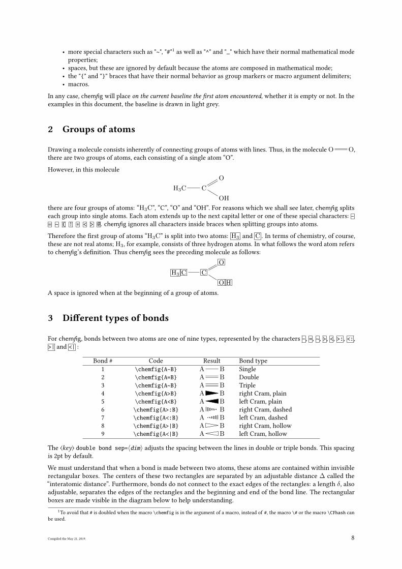
We must understand that when a bond is made between two atoms, these atoms are contained within invisible
rectangular boxes. The centers of these two rectangles are separated by an adjustable distance ∆ called the
“interatomic distance”. Furthermore, bonds do not connect to the exact edges of the rectangles: a length δ, also
adjustable, separates the edges of the rectangles and the beginning and end of the bond line. The rectangular
boxes are made visible in the diagram below to help understanding.
1To avoid that # is doubled when the macro \chemfig is in the argument of a macro, instead of #, the macro \# or the macro \CFhash can
be used.
Compiled the May 21, 2019. 8
A B
δδ∆
The ⟨key⟩ atom sep = ⟨dim⟩ adjusts the interatomic distance ∆. This setting, like all other settings, a�ects all the
following molecules.
\chemfig[atom sep=2em]{A-B}\par\chemfig[atom sep=50pt]{A-B}
A BA B
Interatomic distance
The ⟨key⟩ bond offset = ⟨dim⟩ sets the spacing δ between the bond line and the atom. Its default value is 2pt.
\chemfig[bond offset=0pt]{A-B}\par\chemfig[bond offset=5pt]{A-B}
A BA B
Trimming bonds
If one bond is followed immediately by another, then chemfig inserts an empty group {}. Around this empty
group the separation δ is zero:
\chemfig{A-B=-=C} A B C
Empty groups
The ⟨key⟩ bond style = ⟨tikz code⟩ sets the style for all the bonds drawn thereafter. The ⟨tikz code⟩ is empty by
default. To custom a single bond, see page 13.
\chemfig[bond style={line width=1pt,red}]{A-B=C>|D<E>:F} A B C D E F
Style of bonds
The spacing δ for just one bond can be speci�ed with the character #. This character must be placed immediatelyafter the bond symbol and has one required argument between parentheses of the form “#(〈dim1〉,〈dim2〉)”,
where 〈dim1〉 is the spacing δ at the beginning of the bond and 〈dim2〉 is the that at the end. If 〈dim2〉 is omitted,
the spacing at the end of the bond takes the value of δ in e�ect at that time. One can see in the example how the
shortening, set to 4pt to be more visible, is nulli�ed for the bond arriving at “B”, then for the one leaving “B”, and
�nally for both:
\setchemfig{bond offset=4pt}\chemfig{A-B-C}\par\chemfig{A-#(,0pt)B-C}\par\chemfig{A-B-#(0pt)C}\par\chemfig{A-#(,0pt)B-#(0pt)C}
A B CA B CA B CA B C
Fine adjustment of bond shortening
By default, all atoms within groups of atoms are typeset in math mode (spaces are ignored). They may therefore
contain math mode speci�c commands such as subscripts or superscripts2:
\chemfig{A_1B^2-C _ 3 ^ 4} A1B2 C43
Math mode
There are settings speci�cally for Cram bonds:
• cram width = ⟨dim⟩ is the size of the base of the triangle, and is 1.5pt by default;
• cram dash width = ⟨dim⟩ is the thickness of the dots, and is 1pt by default;
• cram dash sep = ⟨dim⟩ is the spacing between the dots, and is 2pt by default.
Here is an example where the three dimensions are changed:
\chemfig[cram width=10pt,cram dash width=0.4pt,cram dash sep=1pt]{A>B>:C>|D}
A B C D
Modified Cram bonds
2There is a problem with the placement of groups of atoms containing exponents or subscripts. See page 27.
Compiled the May 21, 2019. 9
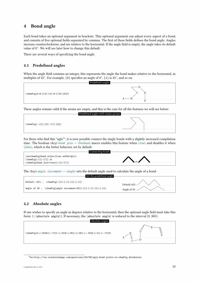
4 Bond angle
Each bond takes an optional argument in brackets. This optional argument can adjust every aspect of a bond,
and consists of �ve optional �elds separated by commas. The �rst of these �elds de�nes the bond angle. Angles
increase counterclockwise, and are relative to the horizontal. If the angle �eld is empty, the angle takes its default
value of 0◦. We will see later how to change this default.
There are several ways of specifying the bond angle.
4.1 Prede�ned angles
When the angle �eld contains an integer, this represents the angle the bond makes relative to the horizontal, in
multiples of 45◦. For example, [0] speci�es an angle of 0
◦, [1] is 45
◦, and so on.
\chemfig{A-B-[1]C-[3]-D-[7]E-[6]F}
A B
C
D
E
F
Predefined angles
These angles remain valid if the atoms are empty, and this is the case for all the features we will see below:
\chemfig{--[1]-[3]--[7]-[6]}
Predefined angles with empty groups
For those who �nd this "ugly3", it is now possible connect the single bonds with a slightly increased compilation
time. The boolean ⟨key⟩ bond join = ⟨boolean⟩ macro enables this feature when ⟨true⟩ and disables it when
⟨false⟩, which is the better behavior, set by default.
\setchemfig{bond style={line width=3pt}}\chemfig{-[1]-[7]} et\chemfig[bond join=true]{-[1]-[7]} et
Connecting bonds
The ⟨key⟩ angle increment = ⟨angle⟩ sets the default angle used to calculate the angle of a bond:
Default (45) : \chemfig{-[1]-[-1]-[1]-[-1]}
Angle of 30 : \chemfig[angle increment=30]{-[1]-[-1]-[1]-[-1]}
Default (45) :
Angle of 30 :
Set the predefined angle
4.2 Absolute angles
If one wishes to specify an angle in degrees relative to the horizontal, then the optional angle �eld must take this
form: [:〈absolute angle〉]. If necessary, the 〈absolute angle〉 is reduced to the interval [0, 360):
\chemfig{A-[:30]B=[:-75]C-[:10]D-[:90]>|[:60]-[:-20]E-[:0]~[:-75]F}
A
B
CD
E
F
Absolute angles
3See http://tex.stackexchange.com/questions/161796/ugly-bond-joints-in-chemfig detokenize
Compiled the May 21, 2019. 10
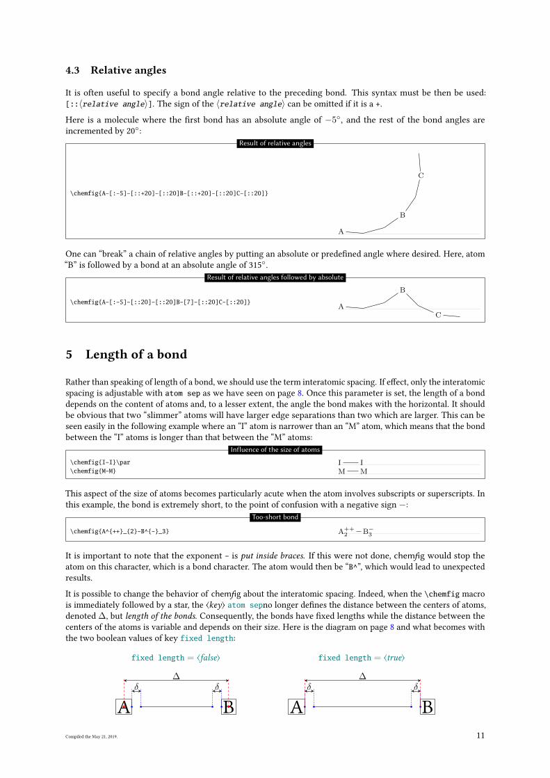
4.3 Relative angles
It is often useful to specify a bond angle relative to the preceding bond. This syntax must be then be used:
[::〈relative angle〉]. The sign of the 〈relative angle〉 can be omitted if it is a +.
Here is a molecule where the �rst bond has an absolute angle of −5◦, and the rest of the bond angles are
incremented by 20◦:
\chemfig{A-[:-5]-[::+20]-[::20]B-[::+20]-[::20]C-[::20]}
A
B
C
Result of relative angles
One can “break” a chain of relative angles by putting an absolute or prede�ned angle where desired. Here, atom
“B” is followed by a bond at an absolute angle of 315◦.
\chemfig{A-[:-5]-[::20]-[::20]B-[7]-[::20]C-[::20]}A
B
C
Result of relative angles followed by absolute
5 Length of a bond
Rather than speaking of length of a bond, we should use the term interatomic spacing. If e�ect, only the interatomic
spacing is adjustable with atom sep as we have seen on page 8. Once this parameter is set, the length of a bond
depends on the content of atoms and, to a lesser extent, the angle the bond makes with the horizontal. It should
be obvious that two “slimmer” atoms will have larger edge separations than two which are larger. This can be
seen easily in the following example where an “I” atom is narrower than an “M” atom, which means that the bond
between the “I” atoms is longer than that between the “M” atoms:
\chemfig{I-I}\par\chemfig{M-M}
I IM M
Influence of the size of atoms
This aspect of the size of atoms becomes particularly acute when the atom involves subscripts or superscripts. In
this example, the bond is extremely short, to the point of confusion with a negative sign −:
\chemfig{A^{++}_{2}-B^{-}_3} A++2 B−3
Too-short bond
It is important to note that the exponent - is put inside braces. If this were not done, chemfig would stop the
atom on this character, which is a bond character. The atom would then be “B^”, which would lead to unexpected
results.
It is possible to change the behavior of chemfig about the interatomic spacing. Indeed, when the \chemfig macro
is immediately followed by a star, the ⟨key⟩ atom sepno longer de�nes the distance between the centers of atoms,
denoted ∆, but length of the bonds. Consequently, the bonds have �xed lengths while the distance between the
centers of the atoms is variable and depends on their size. Here is the diagram on page 8 and what becomes with
the two boolean values of key fixed length:
fixed length = ⟨false⟩ fixed length = ⟨true⟩
A B
δδ∆
A B
δδ∆
Compiled the May 21, 2019. 11
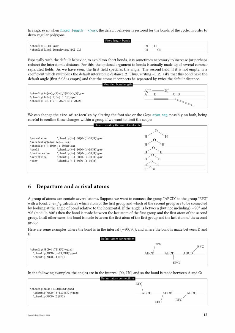
In rings, even when fixed length = ⟨true⟩, the default behavior is restored for the bonds of the cycle, in order to
draw regular polygons.
\chemfig{Cl-Cl}\par\chemfig[fixed length=true]{Cl-Cl}
Cl ClCl Cl
Fixed length bonds
Especially with the default behavior, to avoid too short bonds, it is sometimes necessary to increase (or perhaps
reduce) the interatomic distance. For this, the optional argument to bonds is actually made up of several comma-
separated �elds. As we have seen, the �rst �eld speci�es the angle. The second �eld, if it is not empty, is a
coe�cient which multiplies the default interatomic distance ∆. Thus, writing -[,2] asks that this bond have the
default angle (�rst �eld is empty) and that the atoms it connects be separated by twice the default distance.
\chemfig{A^{++}_{2}-[,2]B^{-}_3}\par\chemfig{A-B-[,2]C=[,0.5]D}\par\chemfig{-=[,1.5]-[,0.75]=[:-20,2]}
A++2 B−3
A B C D
Modified bond length
We can change the size of molecules by altering the font size or the ⟨key⟩ atom sep, possibly on both, being
careful to con�ne these changes within a group if we want to limit the scope:
\normalsize \chemfig{H-[:30]O-[:-30]H}\par\setchemfig{atom sep=2.5em}\chemfig{H-[:30]O-[:-30]H}\par\small \chemfig{H-[:30]O-[:-30]H}\par\footnotesize \chemfig{H-[:30]O-[:-30]H}\par\scriptsize \chemfig{H-[:30]O-[:-30]H}\par\tiny \chemfig{H-[:30]O-[:-30]H}
H
O
H
H
O
H
H
O
H
HO
H
H
O
H
HO
H
How to modify the size of molecule
6 Departure and arrival atoms
A group of atoms can contain several atoms. Suppose we want to connect the group “ABCD” to the group “EFG”
with a bond. chemfig calculates which atom of the �rst group and which of the second group are to be connected
by looking at the angle of bond relative to the horizontal. If the angle is between (but not including) −90◦ and
90◦
(modulo 360◦) then the bond is made between the last atom of the �rst group and the �rst atom of the second
group. In all other cases, the bond is made between the �rst atom of the �rst group and the last atom of the second
group.
Here are some examples where the bond is in the interval (−90, 90), and where the bond is made between D and
E:
\chemfig{ABCD-[:75]EFG}\quad\chemfig{ABCD-[:-85]EFG}\quad\chemfig{ABCD-[1]EFG}
ABCD
EFG
ABCD
EFG
ABCD
EFG
Default atom connections
In the following examples, the angles are in the interval [90, 270] and so the bond is made between A and G:
\chemfig{ABCD-[:100]EFG}\quad\chemfig{ABCD-[:-110]EFG}\quad\chemfig{ABCD-[5]EFG}
ABCD
GFE
ABCD
GFE
ABCD
GFE
Default atom connections
Compiled the May 21, 2019. 12
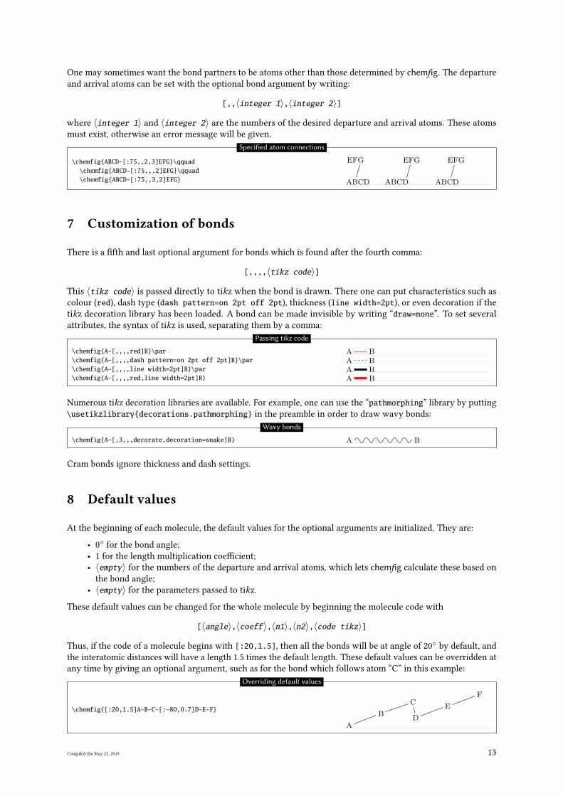
One may sometimes want the bond partners to be atoms other than those determined by chemfig. The departure
and arrival atoms can be set with the optional bond argument by writing:
[,,〈integer 1〉,〈integer 2〉]
where 〈integer 1〉 and 〈integer 2〉 are the numbers of the desired departure and arrival atoms. These atoms
must exist, otherwise an error message will be given.
\chemfig{ABCD-[:75,,2,3]EFG}\qquad\chemfig{ABCD-[:75,,,2]EFG}\qquad\chemfig{ABCD-[:75,,3,2]EFG} ABCD
GFE
ABCD
FGE
ABCD
FGE
Specified atom connections
7 Customization of bonds
There is a �fth and last optional argument for bonds which is found after the fourth comma:
[,,,,〈tikz code〉]
This 〈tikz code〉 is passed directly to tikz when the bond is drawn. There one can put characteristics such as
colour (red), dash type (dash pattern=on 2pt off 2pt), thickness (line width=2pt), or even decoration if the
tikz decoration library has been loaded. A bond can be made invisible by writing “draw=none”. To set several
attributes, the syntax of tikz is used, separating them by a comma:
\chemfig{A-[,,,,red]B}\par\chemfig{A-[,,,,dash pattern=on 2pt off 2pt]B}\par\chemfig{A-[,,,,line width=2pt]B}\par\chemfig{A-[,,,,red,line width=2pt]B}
A BA BA BA B
Passing tikz code
Numerous tikz decoration libraries are available. For example, one can use the “pathmorphing” library by putting
\usetikzlibrary{decorations.pathmorphing} in the preamble in order to draw wavy bonds:
\chemfig{A-[,3,,,decorate,decoration=snake]B} A B
Wavy bonds
Cram bonds ignore thickness and dash settings.
8 Default values
At the beginning of each molecule, the default values for the optional arguments are initialized. They are:
• 0◦
for the bond angle;
• 1 for the length multiplication coe�cient;
• 〈empty〉 for the numbers of the departure and arrival atoms, which lets chemfig calculate these based on
the bond angle;
• 〈empty〉 for the parameters passed to tikz.
These default values can be changed for the whole molecule by beginning the molecule code with
[〈angle〉,〈coeff〉,〈n1〉,〈n2〉,〈code tikz〉]
Thus, if the code of a molecule begins with [:20,1.5], then all the bonds will be at angle of 20◦
by default, and
the interatomic distances will have a length 1.5 times the default length. These default values can be overridden at
any time by giving an optional argument, such as for the bond which follows atom “C” in this example:
\chemfig{[:20,1.5]A-B-C-[:-80,0.7]D-E-F}
A
B
C
D
E
F
Overriding default values
Compiled the May 21, 2019. 13
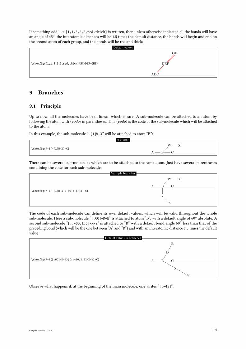
If something odd like [1,1.5,2,2,red,thick] is written, then unless otherwise indicated all the bonds will have
an angle of 45◦, the interatomic distances will be 1.5 times the default distance, the bonds will begin and end on
the second atom of each group, and the bonds will be red and thick:
\chemfig{[1,1.5,2,2,red,thick]ABC-DEF=GHI}
BCA
EFD
HIG
Default values
9 Branches
9.1 Principle
Up to now, all the molecules have been linear, which is rare. A sub-molecule can be attached to an atom by
following the atom with 〈code〉 in parentheses. This 〈code〉 is the code of the sub-molecule which will be attached
to the atom.
In this example, the sub-molecule “-[1]W-X” will be attached to atom “B”:
\chemfig{A-B(-[1]W-X)-C}A B
W X
C
A branch
There can be several sub-molecules which are to be attached to the same atom. Just have several parentheses
containing the code for each sub-molecule:
\chemfig{A-B(-[1]W-X)(-[6]Y-[7]Z)-C}
A B
W X
Y
Z
C
Multiple branches
The code of each sub-molecule can de�ne its own default values, which will be valid throughout the whole
sub-molecule. Here a sub-molecule “[:60]-D-E” is attached to atom “B”, with a default angle of 60◦
absolute. A
second sub-molecule “[::-60,1.5]-X-Y” is attached to “B” with a default bond angle 60◦
less than that of the
preceding bond (which will be the one between “A” and “B”) and with an interatomic distance 1.5 times the default
value:
\chemfig{A-B([:60]-D-E)([::-30,1.5]-X-Y)-C} A B
D
E
X
Y
C
Default values in branches
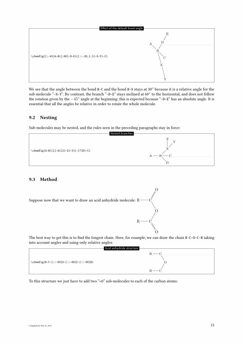
Observe what happens if, at the beginning of the main molecule, one writes “[:-45]”:
Compiled the May 21, 2019. 14
\chemfig{[:-45]A-B([:60]-D-E)([::-30,1.5]-X-Y)-C}
A
B
D
E
X
Y
C
E�ect of the default bond angle
We see that the angle between the bond B-C and the bond B-X stays at 30◦
because it is a relative angle for the
sub-molecule “-X-Y”. By contrast, the branch “-D-E” stays inclined at 60◦
to the horizontal, and does not follow
the rotation given by the −45◦ angle at the beginning; this is expected because “-D-E” has an absolute angle. It is
essential that all the angles be relative in order to rotate the whole molecule.
9.2 Nesting
Sub-molecules may be nested, and the rules seen in the preceding paragraphs stay in force:
\chemfig{A-B([1]-X([2]-Z)-Y)(-[7]D)-C}
A B
X
ZY
D
C
Nested branches
9.3 Method
Suppose now that we want to draw an acid anhydride molecule: R C
O
O
C
O
R
The best way to get this is to �nd the longest chain. Here, for example, we can draw the chain R-C-O-C-R taking
into account angles and using only relative angles:
\chemfig{R-C-[::-60]O-[::-60]C-[::-60]R}
R C
O
CR
Acid anhydride structure
To this structure we just have to add two “=O” sub-molecules to each of the carbon atoms:
Compiled the May 21, 2019. 15
\chemfig{R-C(=[::+60]O)-[::-60]O-[::-60]C(=[::+60]O)-[::-60]R}
R C
O
O
C
O
R
Acid anhydride
Because we used only relative angles, we can rotate this molecule by giving a default angle of e.g. 75◦:
\chemfig{[:75]R-C(=[::+60]O)-[::-60]O-[::-60]C(=[::+60]O)-[::-60]R}
R
C
O
O
CO
R
Rotation of a molecule
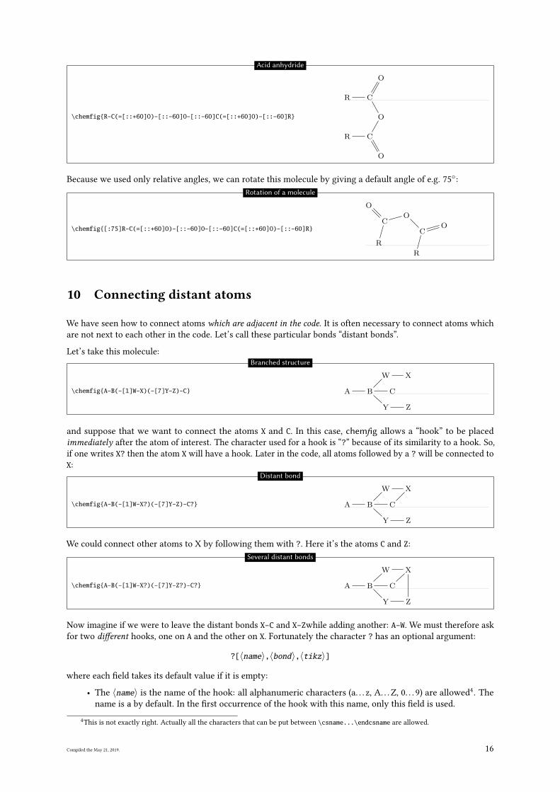
10 Connecting distant atoms
We have seen how to connect atoms which are adjacent in the code. It is often necessary to connect atoms which
are not next to each other in the code. Let’s call these particular bonds “distant bonds”.
Let’s take this molecule:
\chemfig{A-B(-[1]W-X)(-[7]Y-Z)-C} A B
W X
Y Z
C
Branched structure
and suppose that we want to connect the atoms X and C. In this case, chemfig allows a “hook” to be placed
immediately after the atom of interest. The character used for a hook is “?” because of its similarity to a hook. So,
if one writes X? then the atom X will have a hook. Later in the code, all atoms followed by a ? will be connected to
X:
\chemfig{A-B(-[1]W-X?)(-[7]Y-Z)-C?} A B
W X
Y Z
C
Distant bond
We could connect other atoms to X by following them with ?. Here it’s the atoms C and Z:
\chemfig{A-B(-[1]W-X?)(-[7]Y-Z?)-C?} A B
W X
Y Z
C
Several distant bonds
Now imagine if we were to leave the distant bonds X-C and X-Zwhile adding another: A-W. We must therefore ask
for two di�erent hooks, one on A and the other on X. Fortunately the character ? has an optional argument:
?[〈name〉,〈bond〉,〈tikz〉]
where each �eld takes its default value if it is empty:
• The 〈name〉 is the name of the hook: all alphanumeric characters (a. . . z, A. . .Z, 0. . . 9) are allowed4. The
name is a by default. In the �rst occurrence of the hook with this name, only this �eld is used.
4This is not exactly right. Actually all the characters that can be put between \csname...\endcsname are allowed.
Compiled the May 21, 2019. 16
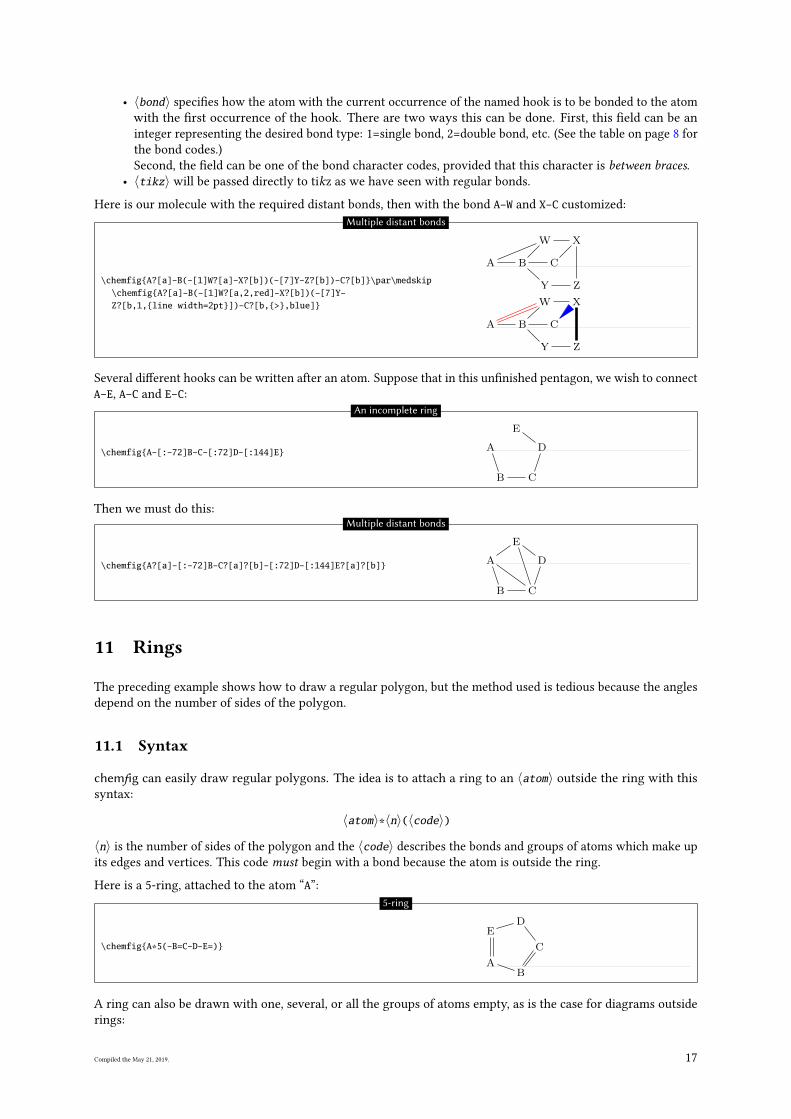
• 〈bond〉 speci�es how the atom with the current occurrence of the named hook is to be bonded to the atom
with the �rst occurrence of the hook. There are two ways this can be done. First, this �eld can be an
integer representing the desired bond type: 1=single bond, 2=double bond, etc. (See the table on page 8 for
the bond codes.)
Second, the �eld can be one of the bond character codes, provided that this character is between braces.• 〈tikz〉 will be passed directly to tikz as we have seen with regular bonds.
Here is our molecule with the required distant bonds, then with the bond A-W and X-C customized:
\chemfig{A?[a]-B(-[1]W?[a]-X?[b])(-[7]Y-Z?[b])-C?[b]}\par\medskip\chemfig{A?[a]-B(-[1]W?[a,2,red]-X?[b])(-[7]Y-Z?[b,1,{line width=2pt}])-C?[b,{>},blue]}
A B
W X
Y Z
C
A B
W X
Y Z
C
Multiple distant bonds
Several di�erent hooks can be written after an atom. Suppose that in this un�nished pentagon, we wish to connect
A-E, A-C and E-C:
\chemfig{A-[:-72]B-C-[:72]D-[:144]E} A
B C
D
E
An incomplete ring
Then we must do this:
\chemfig{A?[a]-[:-72]B-C?[a]?[b]-[:72]D-[:144]E?[a]?[b]} A
B C
D
E
Multiple distant bonds
11 Rings
The preceding example shows how to draw a regular polygon, but the method used is tedious because the angles
depend on the number of sides of the polygon.
11.1 Syntax
chemfig can easily draw regular polygons. The idea is to attach a ring to an 〈atom〉 outside the ring with this
syntax:
〈atom〉*〈n〉(〈code〉)
〈n〉 is the number of sides of the polygon and the 〈code〉 describes the bonds and groups of atoms which make up
its edges and vertices. This code must begin with a bond because the atom is outside the ring.
Here is a 5-ring, attached to the atom “A”:
\chemfig{A*5(-B=C-D-E=)}
AB
C
DE
5-ring
A ring can also be drawn with one, several, or all the groups of atoms empty, as is the case for diagrams outside
rings:
Compiled the May 21, 2019. 17
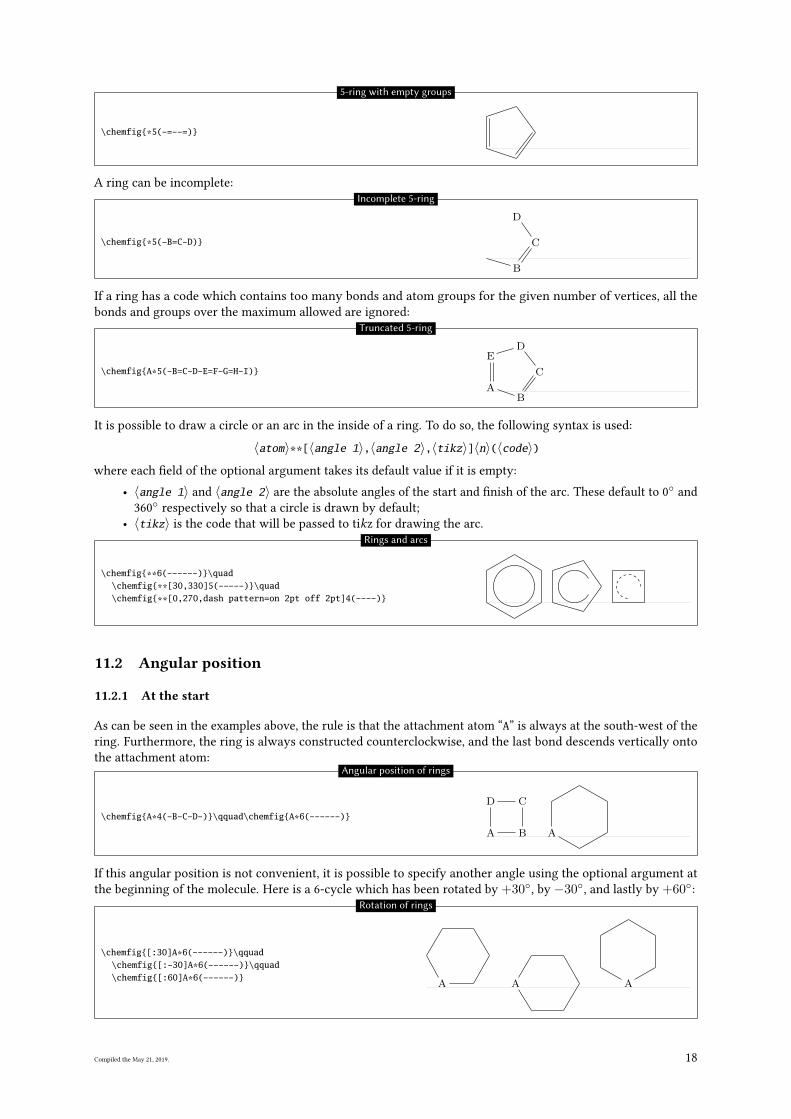
\chemfig{*5(-=--=)}
5-ring with empty groups
A ring can be incomplete:
\chemfig{*5(-B=C-D)}
B
C
D
Incomplete 5-ring
If a ring has a code which contains too many bonds and atom groups for the given number of vertices, all the
bonds and groups over the maximum allowed are ignored:
\chemfig{A*5(-B=C-D-E=F-G=H-I)}
AB
C
DE
Truncated 5-ring
It is possible to draw a circle or an arc in the inside of a ring. To do so, the following syntax is used:
〈atom〉**[〈angle 1〉,〈angle 2〉,〈tikz〉]〈n〉(〈code〉)where each �eld of the optional argument takes its default value if it is empty:
• 〈angle 1〉 and 〈angle 2〉 are the absolute angles of the start and �nish of the arc. These default to 0◦
and
360◦
respectively so that a circle is drawn by default;
• 〈tikz〉 is the code that will be passed to tikz for drawing the arc.
\chemfig{**6(------)}\quad\chemfig{**[30,330]5(-----)}\quad\chemfig{**[0,270,dash pattern=on 2pt off 2pt]4(----)}
Rings and arcs
11.2 Angular position
11.2.1 At the start
As can be seen in the examples above, the rule is that the attachment atom “A” is always at the south-west of the
ring. Furthermore, the ring is always constructed counterclockwise, and the last bond descends vertically onto
the attachment atom:
\chemfig{A*4(-B-C-D-)}\qquad\chemfig{A*6(------)}
A B
CD
A
Angular position of rings
If this angular position is not convenient, it is possible to specify another angle using the optional argument at
the beginning of the molecule. Here is a 6-cycle which has been rotated by +30◦, by −30◦, and lastly by +60◦:
\chemfig{[:30]A*6(------)}\qquad\chemfig{[:-30]A*6(------)}\qquad\chemfig{[:60]A*6(------)} A A A
Rotation of rings
Compiled the May 21, 2019. 18
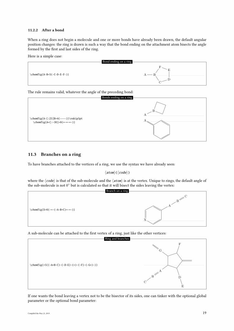
11.2.2 After a bond
When a ring does not begin a molecule and one or more bonds have already been drawn, the default angular
position changes: the ring is drawn is such a way that the bond ending on the attachment atom bisects the angle
formed by the �rst and last sides of the ring.
Here is a simple case:
\chemfig{A-B*5(-C-D-E-F-)} A B
CD
EF
Bond ending on a ring
The rule remains valid, whatever the angle of the preceding bond:
\chemfig{A-[:25]B*4(----)}\vskip5pt\chemfig{A=[:-30]*6(=-=-=-)}
A
B
A
Bonds ending on a ring
11.3 Branches on a ring
To have branches attached to the vertices of a ring, we use the syntax we have already seen:
〈atom〉(〈code〉)
where the 〈code〉 is that of the sub-molecule and the 〈atom〉 is at the vertex. Unique to rings, the default angle of
the sub-molecule is not 0◦
but is calculated so that it will bisect the sides leaving the vertex:
\chemfig{X*6(-=-(-A-B=C)=-=-)}
X
A
B
C
Branch on a ring
A sub-molecule can be attached to the �rst vertex of a ring, just like the other vertices:
\chemfig{*5((-A=B-C)-(-D-E)-(=)-(-F)-(-G=)-)}
A
B
C
D
E
F
G
Ring and branches
If one wants the bond leaving a vertex not to be the bisector of its sides, one can tinker with the optional global
parameter or the optional bond parameter:
Compiled the May 21, 2019. 19
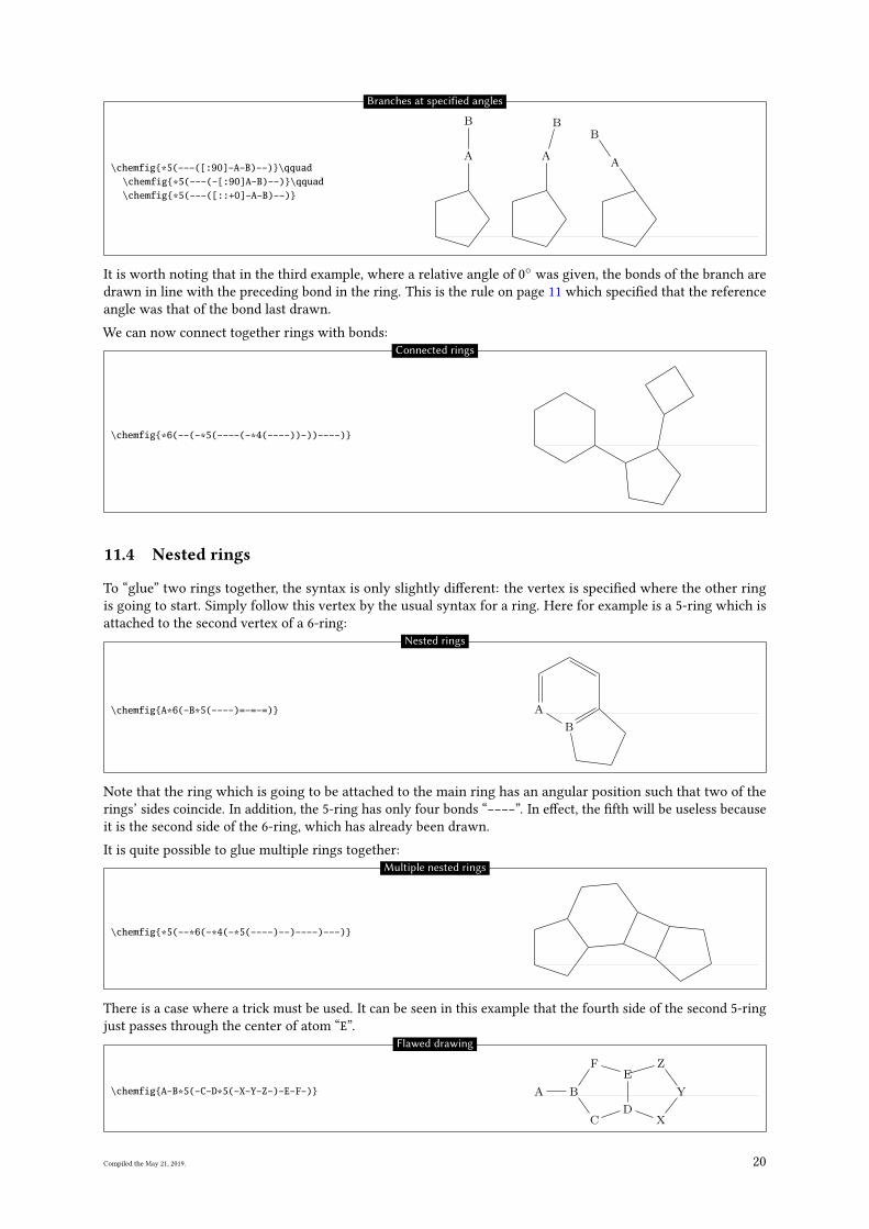
\chemfig{*5(---([:90]-A-B)--)}\qquad\chemfig{*5(---(-[:90]A-B)--)}\qquad\chemfig{*5(---([::+0]-A-B)--)}
A
B
A
B
A
B
Branches at specified angles
It is worth noting that in the third example, where a relative angle of 0◦
was given, the bonds of the branch are
drawn in line with the preceding bond in the ring. This is the rule on page 11 which speci�ed that the reference
angle was that of the bond last drawn.
We can now connect together rings with bonds:
\chemfig{*6(--(-*5(----(-*4(----))-))----)}
Connected rings
11.4 Nested rings
To “glue” two rings together, the syntax is only slightly di�erent: the vertex is speci�ed where the other ring
is going to start. Simply follow this vertex by the usual syntax for a ring. Here for example is a 5-ring which is
attached to the second vertex of a 6-ring:
\chemfig{A*6(-B*5(----)=-=-=)} A
B
Nested rings
Note that the ring which is going to be attached to the main ring has an angular position such that two of the
rings’ sides coincide. In addition, the 5-ring has only four bonds “----”. In e�ect, the �fth will be useless because
it is the second side of the 6-ring, which has already been drawn.
It is quite possible to glue multiple rings together:
\chemfig{*5(--*6(-*4(-*5(----)--)----)---)}
Multiple nested rings
There is a case where a trick must be used. It can be seen in this example that the fourth side of the second 5-ring
just passes through the center of atom “E”.
\chemfig{A-B*5(-C-D*5(-X-Y-Z-)-E-F-)} A B
CD
X
Y
ZE
F
Flawed drawing
Compiled the May 21, 2019. 20
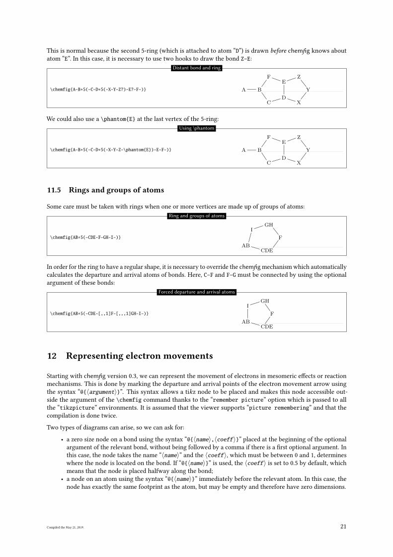
This is normal because the second 5-ring (which is attached to atom “D”) is drawn before chemfig knows about
atom “E”. In this case, it is necessary to use two hooks to draw the bond Z-E:
\chemfig{A-B*5(-C-D*5(-X-Y-Z?)-E?-F-)} A B
CD
X
Y
ZE
F
Distant bond and ring
We could also use a \phantom{E} at the last vertex of the 5-ring:
\chemfig{A-B*5(-C-D*5(-X-Y-Z-\phantom{E})-E-F-)} A B
CD
X
Y
ZE
F
Using \phantom
11.5 Rings and groups of atoms
Some care must be taken with rings when one or more vertices are made up of groups of atoms:
\chemfig{AB*5(-CDE-F-GH-I-)}
ABCDE
F
HGI
Ring and groups of atoms
In order for the ring to have a regular shape, it is necessary to override the chemfig mechanism which automatically
calculates the departure and arrival atoms of bonds. Here, C-F and F-G must be connected by using the optional
argument of these bonds:
\chemfig{AB*5(-CDE-[,,1]F-[,,,1]GH-I-)}
ABCDE
F
GHI
Forced departure and arrival atoms
12 Representing electron movements
Starting with chemfig version 0.3, we can represent the movement of electrons in mesomeric e�ects or reaction
mechanisms. This is done by marking the departure and arrival points of the electron movement arrow using
the syntax “@{〈argument〉}”. This syntax allows a tikz node to be placed and makes this node accessible out-
side the argument of the \chemfig command thanks to the “remember picture” option which is passed to all
the “tikzpicture” environments. It is assumed that the viewer supports “picture remembering” and that the
compilation is done twice.
Two types of diagrams can arise, so we can ask for:
• a zero size node on a bond using the syntax “@{〈name〉,〈coeff〉}” placed at the beginning of the optional
argument of the relevant bond, without being followed by a comma if there is a �rst optional argument. In
this case, the node takes the name “〈name〉” and the 〈coeff〉, which must be between 0 and 1, determines
where the node is located on the bond. If “@{〈name〉}” is used, the 〈coeff〉 is set to 0.5 by default, which
means that the node is placed halfway along the bond;
• a node on an atom using the syntax “@{〈name〉}” immediately before the relevant atom. In this case, the
node has exactly the same footprint as the atom, but may be empty and therefore have zero dimensions.
Compiled the May 21, 2019. 21
Once the \chemfig command has drawn the molecule(s) and has placed the nodes with the syntax described
above, we can connect these nodes to each other with tikz instructions. These instructions are placed in the
argument of the command \chemmove5and has the following syntax if (for example) we need to connect a node
named “〈name1〉” to the node named “〈name2〉”:
\chemmove[〈opt〉]{\draw[〈tikz opt〉](〈name1〉)〈tikz link〉(〈name2〉);}
The optional argument 〈opt〉 of the \chemmove command will be added to the argument of the tikzpictureenvironment in which the links between the nodes will be drawn. The 〈tikz opt〉 and 〈tikz link〉 instructions
are describe in detail in the documentation of the tikz package.
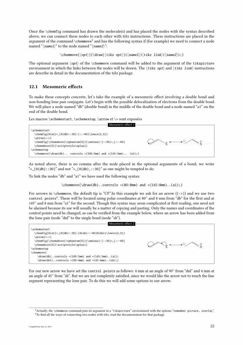
12.1 Mesomeric e�ects
To make these concepts concrete, let’s take the example of a mesomeric e�ect involving a double bond and
non-bonding lone pair conjugate. Let’s begin with the possible delocalization of electrons from the double bond.
We will place a node named “db” (double bond) in the middle of the double bond and a node named “a1” on the
end of the double bond.
Les macros \schemestart, \schemestop, \arrow et \+ sont exposées
\schemestart\chemfig{@{a1}=_[@{db}::30]-[::-60]\lewis{2,X}}\arrow{<->}\chemfig{\chemabove{\vphantom{X}}{\ominus}-[::30]=_[::-60]\chemabove{X}{\scriptstyle\oplus}}
\schemestop\chemmove{\draw(db).. controls +(100:5mm) and +(145:5mm).. (a1);}
X ⊕
X
Mesomeric e�ect 1
As noted above, there is no comma after the node placed in the optional arguments of a bond; we write
“=_[@{db}::30]” and not “=_[@{db},::30]” as one might be tempted to do.
To link the nodes “db” and “a1” we have used the following syntax:
\chemmove{\draw(db)..controls +(80:8mm) and +(145:8mm)..(a1);}
For arrows in \chemmove, the default tip is “CF”.In this example we ask for an arrow ([->]) and we use two
control points6. These will be located using polar coordinates at 80
◦and 8 mm from “db” for the �rst and at
145◦
and 8 mm from “a1” for the second. Though this syntax may seem complicated at �rst reading, one need not
be alarmed because its use will usually be a matter of copying and pasting. Only the names and coordinates of the
control points need be changed, as can be veri�ed from the example below, where an arrow has been added from
the lone pair (node “dnl” to the single bond (node “sb”).
\schemestart\chemfig{@{a1}=_[@{db}::30]-[@{sb}::-60]@{dnl}\lewis{2,X}}\arrow{<->}\chemfig{\chemabove{\vphantom{X}}{\ominus}-[::30]=_[::-60]\chemabove{X}{\scriptstyle\oplus}}
\schemestop\chemmove{
\draw(db)..controls +(100:5mm) and +(145:5mm)..(a1);\draw(dnl)..controls +(90:4mm) and +(45:4mm)..(sb);}
X ⊕
X
Mesomeric e�ect 2
For our new arrow we have set the control points as follows: 4 mm at an angle of 90◦
from “dnl” and 4 mm at
an angle of 45◦
from “sb”. But we are not completely satis�ed, since we would like the arrow not to touch the line
segment representing the lone pair. To do this we will add some options to our arrow.
5Actually, the \chemmove command puts its argument in a “tikzpicture” environment with the options “remember picture, overlay”.
6To �nd all the ways of connecting two nodes with tikz, read the documentation for that package.
Compiled the May 21, 2019. 22
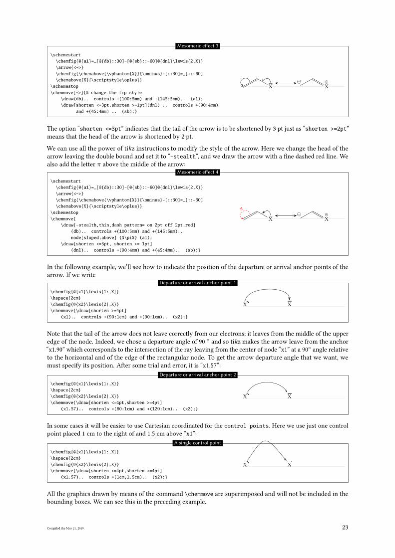
\schemestart\chemfig{@{a1}=_[@{db}::30]-[@{sb}::-60]@{dnl}\lewis{2,X}}\arrow{<->}\chemfig{\chemabove{\vphantom{X}}{\ominus}-[::30]=_[::-60]\chemabove{X}{\scriptstyle\oplus}}
\schemestop\chemmove[->]{% change the tip style
\draw(db).. controls +(100:5mm) and +(145:5mm).. (a1);\draw[shorten <=3pt,shorten >=1pt](dnl) .. controls +(90:4mm)
and +(45:4mm) .. (sb);}
X ⊕
X
Mesomeric e�ect 3
The option “shorten <=3pt” indicates that the tail of the arrow is to be shortened by 3 pt just as “shorten >=2pt”
means that the head of the arrow is shortened by 2 pt.
We can use all the power of tikz instructions to modify the style of the arrow. Here we change the head of the
arrow leaving the double bound and set it to “-stealth”, and we draw the arrow with a �ne dashed red line. We
also add the letter π above the middle of the arrow:
\schemestart\chemfig{@{a1}=_[@{db}::30]-[@{sb}::-60]@{dnl}\lewis{2,X}}\arrow{<->}\chemfig{\chemabove{\vphantom{X}}{\ominus}-[::30]=_[::-60]\chemabove{X}{\scriptstyle\oplus}}
\schemestop\chemmove{
\draw[-stealth,thin,dash pattern= on 2pt off 2pt,red](db).. controls +(100:5mm) and +(145:5mm)..node[sloped,above] {$\pi$} (a1);
\draw[shorten <=3pt, shorten >= 1pt](dnl).. controls +(90:4mm) and +(45:4mm).. (sb);}
X ⊕
X
π
Mesomeric e�ect 4
In the following example, we’ll see how to indicate the position of the departure or arrival anchor points of the
arrow. If we write
\chemfig{@{x1}\lewis{1:,X}}\hspace{2cm}\chemfig{@{x2}\lewis{2|,X}}\chemmove{\draw[shorten >=4pt]
(x1).. controls +(90:1cm) and +(90:1cm).. (x2);}
X X
Departure or arrival anchor point 1
Note that the tail of the arrow does not leave correctly from our electrons; it leaves from the middle of the upper
edge of the node. Indeed, we chose a departure angle of 90◦
and so tikz makes the arrow leave from the anchor
“x1.90” which corresponds to the intersection of the ray leaving from the center of node “x1” at a 90◦
angle relative
to the horizontal and of the edge of the rectangular node. To get the arrow departure angle that we want, we
must specify its position. After some trial and error, it is “x1.57”:
\chemfig{@{x1}\lewis{1:,X}}\hspace{2cm}\chemfig{@{x2}\lewis{2|,X}}\chemmove{\draw[shorten <=4pt,shorten >=4pt]
(x1.57).. controls +(60:1cm) and +(120:1cm).. (x2);}
X X
Departure or arrival anchor point 2
In some cases it will be easier to use Cartesian coordinated for the control points. Here we use just one control
point placed 1 cm to the right of and 1.5 cm above “x1”:
\chemfig{@{x1}\lewis{1:,X}}\hspace{2cm}\chemfig{@{x2}\lewis{2|,X}}\chemmove{\draw[shorten <=4pt,shorten >=4pt]
(x1.57).. controls +(1cm,1.5cm).. (x2);}
X X
A single control point
All the graphics drawn by means of the command \chemmove are superimposed and will not be included in the
bounding boxes. We can see this in the preceding example.
Compiled the May 21, 2019. 23
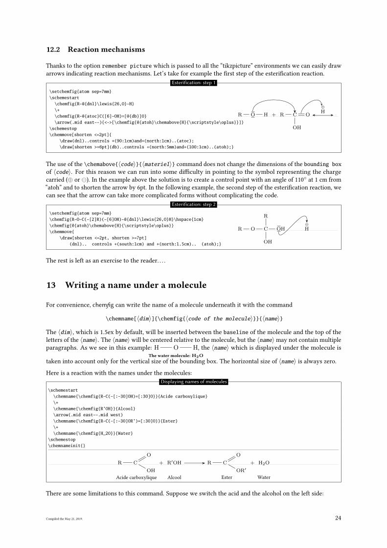
12.2 Reaction mechanisms
Thanks to the option remenber picture which is passed to all the “tikzpicture” environments we can easily draw
arrows indicating reaction mechanisms. Let’s take for example the �rst step of the esteri�cation reaction.
\setchemfig{atom sep=7mm}\schemestart
\chemfig{R-@{dnl}\lewis{26,O}-H}\+\chemfig{R-@{atoc}C([6]-OH)=[@{db}]O}\arrow(.mid east--){<->[\chemfig{@{atoh}\chemabove{H}{\scriptstyle\oplus}}]}
\schemestop\chemmove[shorten <=2pt]{
\draw(dnl)..controls +(90:1cm)and+(north:1cm)..(atoc);\draw[shorten >=6pt](db)..controls +(north:5mm)and+(100:1cm)..(atoh);}
R O H + R C
OH
O
⊕H
Esterification: step 1
The use of the \chemabove{〈code〉}{〈materiel〉} command does not change the dimensions of the bounding boxof 〈code〉. For this reason we can run into some di�culty in pointing to the symbol representing the charge
carried (⊕ or ). In the example above the solution is to create a control point with an angle of 110◦
at 1 cm from
“atoh” and to shorten the arrow by 6pt. In the following example, the second step of the esteri�cation reaction, we
can see that the arrow can take more complicated forms without complicating the code.
\setchemfig{atom sep=7mm}\chemfig{R-O-C(-[2]R)(-[6]OH)-@{dnl}\lewis{26,O}H}\hspace{1cm}\chemfig{@{atoh}\chemabove{H}{\scriptstyle\oplus}}\chemmove{
\draw[shorten <=2pt, shorten >=7pt](dnl).. controls +(south:1cm) and +(north:1.5cm).. (atoh);}
R O C
R
OH
OH⊕H
Esterification: step 2
The rest is left as an exercise to the reader. . . .
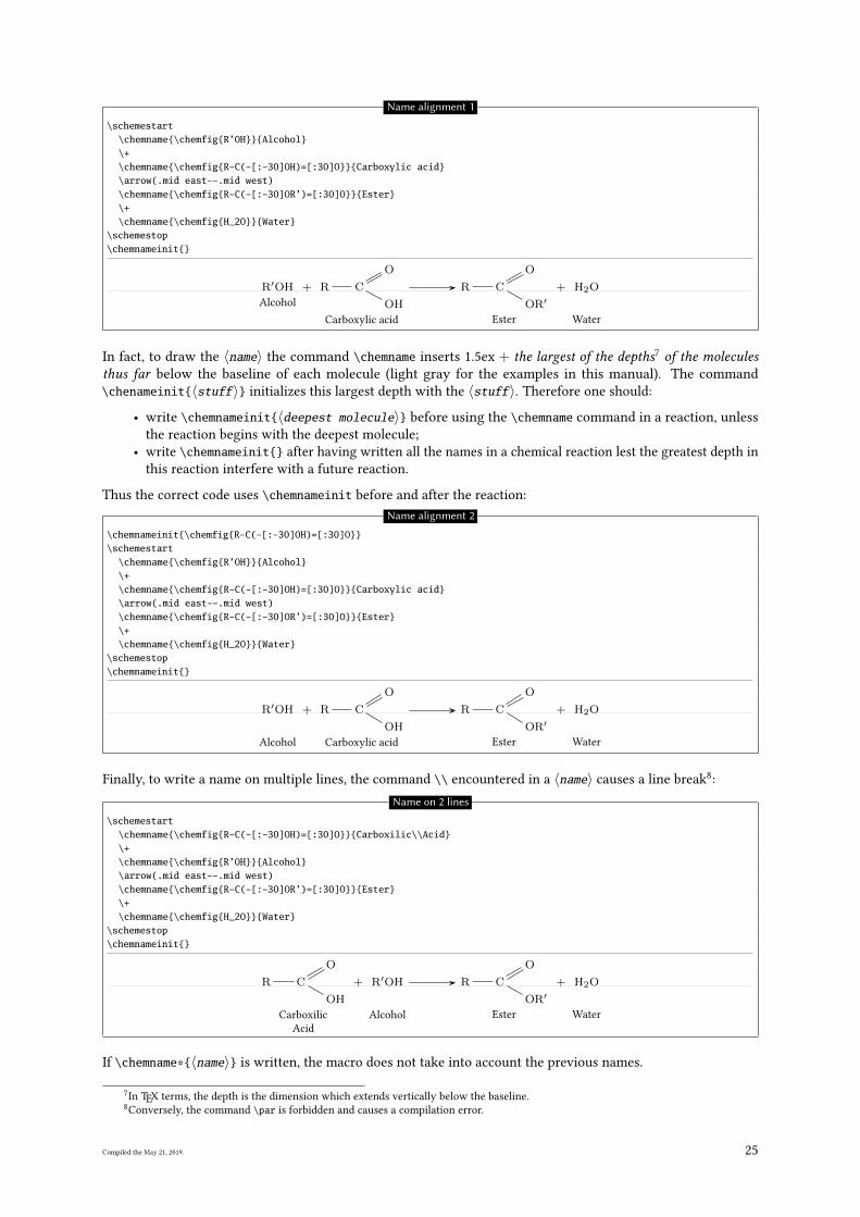
13 Writing a name under a molecule
For convenience, chemfig can write the name of a molecule underneath it with the command
\chemname[〈dim〉]{\chemfig{〈code of the molecule〉}}{〈name〉}
The 〈dim〉, which is 1.5ex by default, will be inserted between the baseline of the molecule and the top of the
letters of the 〈name〉. The 〈name〉 will be centered relative to the molecule, but the 〈name〉may not contain multiple
paragraphs. As we see in this example: H O HThe water molecule: H2O
, the 〈name〉 which is displayed under the molecule is
taken into account only for the vertical size of the bounding box. The horizontal size of 〈name〉 is always zero.
Here is a reaction with the names under the molecules:
Displaying names of molecules
\schemestart\chemname{\chemfig{R-C(-[:-30]OH)=[:30]O}}{Acide carboxylique}\+\chemname{\chemfig{R’OH}}{Alcool}\arrow(.mid east--.mid west)\chemname{\chemfig{R-C(-[:-30]OR’)=[:30]O}}{Ester}\+\chemname{\chemfig{H_2O}}{Water}
\schemestop\chemnameinit{}
R C
OH
O
Acide carboxylique
+ R′OH
Alcool
R C
OR′
O
Ester
+ H2O
Water
There are some limitations to this command. Suppose we switch the acid and the alcohol on the left side:
Compiled the May 21, 2019. 24
Name alignment 1
\schemestart\chemname{\chemfig{R’OH}}{Alcohol}\+\chemname{\chemfig{R-C(-[:-30]OH)=[:30]O}}{Carboxylic acid}\arrow(.mid east--.mid west)\chemname{\chemfig{R-C(-[:-30]OR’)=[:30]O}}{Ester}\+\chemname{\chemfig{H_2O}}{Water}
\schemestop\chemnameinit{}
R′OH
Alcohol
+ R C
OH
O
Carboxylic acid
R C
OR′
O
Ester
+ H2O
Water
In fact, to draw the 〈name〉 the command \chemname inserts 1.5ex + the largest of the depths7 of the moleculesthus far below the baseline of each molecule (light gray for the examples in this manual). The command
\chenameinit{〈stuff〉} initializes this largest depth with the 〈stuff〉. Therefore one should:
• write \chemnameinit{〈deepest molecule〉} before using the \chemname command in a reaction, unless
the reaction begins with the deepest molecule;
• write \chemnameinit{} after having written all the names in a chemical reaction lest the greatest depth in
this reaction interfere with a future reaction.
Thus the correct code uses \chemnameinit before and after the reaction:
Name alignment 2
\chemnameinit{\chemfig{R-C(-[:-30]OH)=[:30]O}}\schemestart
\chemname{\chemfig{R’OH}}{Alcohol}\+\chemname{\chemfig{R-C(-[:-30]OH)=[:30]O}}{Carboxylic acid}\arrow(.mid east--.mid west)\chemname{\chemfig{R-C(-[:-30]OR’)=[:30]O}}{Ester}\+\chemname{\chemfig{H_2O}}{Water}
\schemestop\chemnameinit{}
R′OH
Alcohol
+ R C
OH
O
Carboxylic acid
R C
OR′
O
Ester
+ H2O
Water
Finally, to write a name on multiple lines, the command \\ encountered in a 〈name〉 causes a line break8:
Name on 2 lines
\schemestart\chemname{\chemfig{R-C(-[:-30]OH)=[:30]O}}{Carboxilic\\Acid}\+\chemname{\chemfig{R’OH}}{Alcohol}\arrow(.mid east--.mid west)\chemname{\chemfig{R-C(-[:-30]OR’)=[:30]O}}{Ester}\+\chemname{\chemfig{H_2O}}{Water}
\schemestop\chemnameinit{}
R C
OH
O
Carboxilic
Acid
+ R′OH
Alcohol
R C
OR′
O
Ester
+ H2O
Water
If \chemname*{〈name〉} is written, the macro does not take into account the previous names.
7In TEX terms, the depth is the dimension which extends vertically below the baseline.
8Conversely, the command \par is forbidden and causes a compilation error.
Compiled the May 21, 2019. 25
Advanced usage
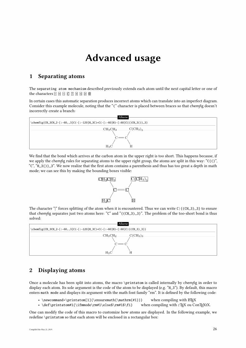
1 Separating atoms
The separating atom mechanism described previously extends each atom until the next capital letter or one of
the characters - = ~ ( ! * < > @
In certain cases this automatic separation produces incorrect atoms which can translate into an imperfect diagram.
Consider this example molecule, noting that the “(” character is placed between braces so that chemfig doesn’t
incorrectly create a branch:
Alkene
\chemfig{CH_3CH_2-[:-60,,3]C(-[:-120]H_3C)=C(-[:-60]H)-[:60]C{(}CH_3{)}_3}
CH3CH2
C
CH3
C
H
C(CH3)3
We �nd that the bond which arrives at the carbon atom in the upper right is too short. This happens because, if
we apply the chemfig rules for separating atoms to the upper right group, the atoms are split in this way: “C{(}”,
“C”, “H_3{)}_3”. We now realize that the �rst atom contains a parenthesis and thus has too great a depth in math
mode; we can see this by making the bounding boxes visible:
CH3CH2
C
CH3
C
H
C(CH3)3
The character “|” forces splitting of the atom when it is encountered. Thus we can write C|{(CH_3)_3} to ensure
that chemfig separates just two atoms here: “C” and “{(CH_3)_3}”. The problem of the too-short bond is thus
solved:
Alkene
\chemfig{CH_3CH_2-[:-60,,3]C(-[:-120]H_3C)=C(-[:-60]H)-[:60]C|{(CH_3)_3}}
CH3CH2
C
CH3
C
H
C(CH3)3
2 Displaying atoms
Once a molecule has been split into atoms, the macro \printatom is called internally by chemfig in order to
display each atom. Its sole argument is the code of the atom to be displayed (e.g. “H_3”). By default, this macro
enters math mode and displays its argument with the math font family “rm”. It is de�ned by the following code:
• \newcommand*\printatom[1]{\ensuremath{\mathrm{#1}}} when compiling with LATEX
• \def\printatom#1{\ifmmode\rm#1\else$\rm#1$\fi} when compiling with εTEX ou ConTEXtX.
One can modify the code of this macro to customize how atoms are displayed. In the following example, we
rede�ne \printatom so that each atom will be enclosed in a rectangular box:
Compiled the May 21, 2019. 26
\fboxsep=1pt\renewcommand*\printatom[1]{\fbox{\ensuremath{\mathrm{#1}}}}\chemfig{H_3C-C(=[:30]O)(-[:-30]OH)}
H3 C C
O
O H
Redefinition of \printatom
Here is how to rede�ne it to use the “sf” font family of math mode:
\renewcommand*\printatom[1]{\ensuremath{\mathsf{#1}}}\chemfig{H_3C-C(=[:30]O)(-[:-30]OH)} H3C C
O
OH
Atoms displayed with “sf” font family
3 Arguments given to tikz
The ⟨key⟩ chemfig style contains tikz instructions which will be passed to the tikzpicture environment in
which the molecule is drawn. On the other hand, the The ⟨key⟩ atom style contains tikz instructions which will
be executed when each node; these instructions are added to the end of every node/.style{<argument>}, i.e.
after the fhe following instructions: “anchor=base,inner sep=0pt,outer sep=0pt,minimum size=0pt”.
With the use of the �rst optional argument one can, for example, choose the global color or thickness of lines:
\chemfig{A-B-[2]C}\par\medskip\setchemfig{chemfig style={line width=1.5pt}}\chemfig{A-B-[2]C}\par\medskip\setchemfig{chemfig style=red}\chemfig{A-B-[2]C}
A B
C
A B
C
A B
C
Style choice
With node style, one can choose the colour of nodes drawn by tikz, change the angle of the drawing or its scale:
\chemfig{A-B-[2]C}\par\medskip\setchemfig{atom style=red}\chemfig{A-B-[2]C}\par\medskip\setchemfig{atom style={rotate=20}}\chemfig{A-B-[2]C}\par\medskip\setchemfig{atom style={scale=0.5}}\chemfig{A-B-[2]C}
A B
C
A B
C
AB
C
A B
C
Style choices
4 Vertical alignment
In some cases with condensed structural diagram of molecules having horizontal bonds, the placement of groups
of atoms is incorrect.
Careful study of the following example shows that the groups of atoms are not correctly aligned on the baseline:
Vertical placement
\Huge\setchemfig{atom sep=2em}\chemfig{A^1-B-C-D}\qquad
Compiled the May 21, 2019. 27
\chemfig{E_1-F-G-H}
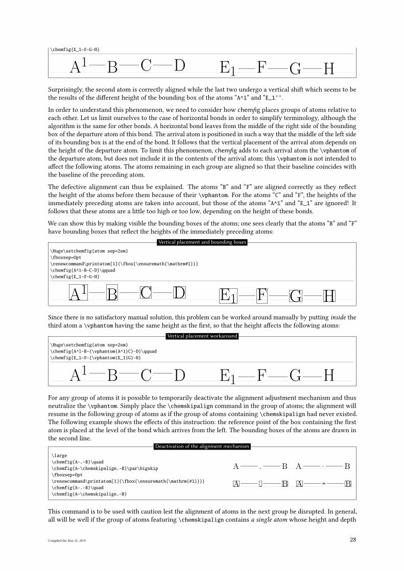
A1 B C D E1 F G HSurprisingly, the second atom is correctly aligned while the last two undergo a vertical shift which seems to be
the results of the di�erent height of the bounding box of the atoms “A^1” and “E_1’’.
In order to understand this phenomenon, we need to consider how chemfig places groups of atoms relative to
each other. Let us limit ourselves to the case of horizontal bonds in order to simplify terminology, although the
algorithm is the same for other bonds. A horizontal bond leaves from the middle of the right side of the bounding
box of the departure atom of this bond. The arrival atom is positioned in such a way that the middle of the left side
of its bounding box is at the end of the bond. It follows that the vertical placement of the arrival atom depends on
the height of the departure atom. To limit this phenomenon, chemfig adds to each arrival atom the \vphantom of
the departure atom, but does not include it in the contents of the arrival atom; this \vphantom is not intended to
a�ect the following atoms. The atoms remaining in each group are aligned so that their baseline coincides with
the baseline of the preceding atom.
The defective alignment can thus be explained. The atoms “B” and “F” are aligned correctly as they re�ect
the height of the atoms before them because of their \vphantom. For the atoms “C” and “F”, the heights of the
immediately preceding atoms are taken into account, but those of the atoms “A^1” and “E_1” are ignored! It
follows that these atoms are a little too high or too low, depending on the height of these bonds.
We can show this by making visible the bounding boxes of the atoms; one sees clearly that the atoms “B” and “F”
have bounding boxes that re�ect the heights of the immediately preceding atoms:
Vertical placement and bounding boxes
\Huge\setchemfig{atom sep=2em}\fboxsep=0pt\renewcommand\printatom[1]{\fbox{\ensuremath{\mathrm#1}}}\chemfig{A^1-B-C-D}\qquad\chemfig{E_1-F-G-H}
A1 B C D E1 F G HSince there is no satisfactory manual solution, this problem can be worked around manually by putting inside the
third atom a \vphantom having the same height as the �rst, so that the height a�ects the following atoms:
Vertical placement workaround
\Huge\setchemfig{atom sep=2em}\chemfig{A^1-B-{\vphantom{A^1}C}-D}\qquad\chemfig{E_1-F-{\vphantom{E_1}G}-H}
A1 B C D E1 F G HFor any group of atoms it is possible to temporarily deactivate the alignment adjustment mechanism and thus
neutralize the \vphantom. Simply place the \chemskipalign command in the group of atoms; the alignment will
resume in the following group of atoms as if the group of atoms containing \chemskipalign had never existed.
The following example shows the e�ects of this instruction: the reference point of the box containing the �rst
atom is placed at the level of the bond which arrives from the left. The bounding boxes of the atoms are drawn in
the second line.
\large\chemfig{A-.-B}\quad\chemfig{A-\chemskipalign.-B}\par\bigskip\fboxsep=0pt\renewcommand\printatom[1]{\fbox{\ensuremath{\mathrm{#1}}}}\chemfig{A-.-B}\quad\chemfig{A-\chemskipalign.-B}
A . B A . B
A . B A . B
Deactivation of the alignment mechanism
This command is to be used with caution lest the alignment of atoms in the next group be disrupted. In general,
all will be well if the group of atoms featuring \chemskipalign contains a single atom whose height and depth
Compiled the May 21, 2019. 28
are less than those of the preceding and following atoms, and if the preceding and following atoms have identical
heights and depths. Here is an example of the mess that results when the group of atoms contains two atoms,
here “\chemskipalign.” and “B”:
\large\fboxsep=0pt\renewcommand\printatom[1]{\fbox{\ensuremath{\mathrm{#1}}}}\chemfig{A-\chemskipalign.B-C}
A .B C
Consequence of the \chemskipaligncommand
This feature can sometimes be useful. Suppose we want to draw the following molecule
A B
We can de�ne commands which will draw the empty and full disks with tikz. To ensure that these disks are at the
right height, namely the height of the bond arriving at them, we will use the command \chemskipalign. In the
second line below the bonds are “stuck” to the disks by using the ability to change the bond shortening with the
“#” character, a feature seen on page 9.
\def\emptydisk{\chemskipalign\tikz\draw(0,0)circle(2pt);}\def\fulldisk{\chemskipalign\tikz\fill(0,0)circle(2pt);}\chemfig{A-\emptydisk-\fulldisk-B}\par\chemfig{A-#(,0pt)\emptydisk-#(0pt,0pt)\fulldisk-#(0pt)B}
A BA B
Use of \chemskipalign and #
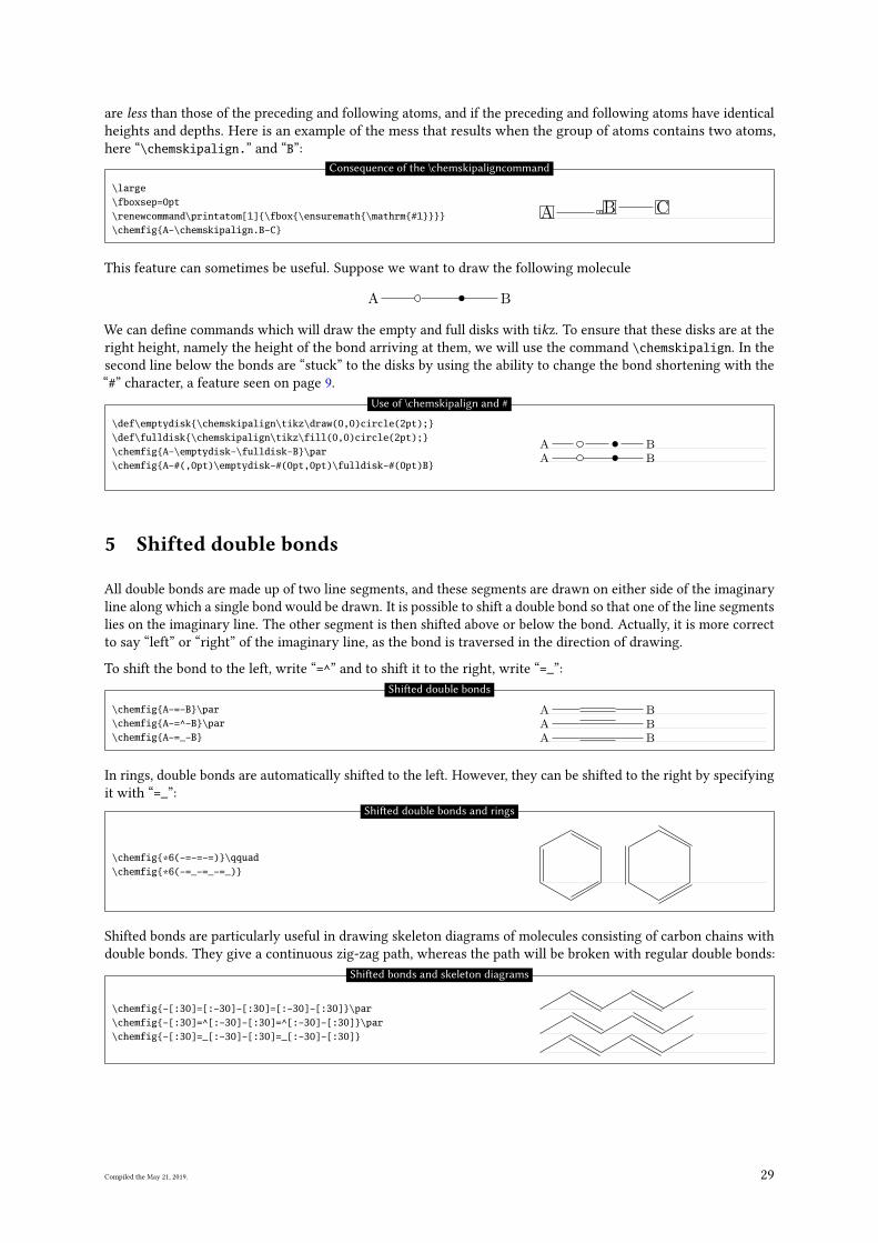
5 Shifted double bonds
All double bonds are made up of two line segments, and these segments are drawn on either side of the imaginary
line along which a single bond would be drawn. It is possible to shift a double bond so that one of the line segments
lies on the imaginary line. The other segment is then shifted above or below the bond. Actually, it is more correct
to say “left” or “right” of the imaginary line, as the bond is traversed in the direction of drawing.
To shift the bond to the left, write “=^” and to shift it to the right, write “=_”:
\chemfig{A-=-B}\par\chemfig{A-=^-B}\par\chemfig{A-=_-B}
A BA BA B
Shi�ed double bonds
In rings, double bonds are automatically shifted to the left. However, they can be shifted to the right by specifying
it with “=_”:
\chemfig{*6(-=-=-=)}\qquad\chemfig{*6(-=_-=_-=_)}
Shi�ed double bonds and rings
Shifted bonds are particularly useful in drawing skeleton diagrams of molecules consisting of carbon chains with
double bonds. They give a continuous zig-zag path, whereas the path will be broken with regular double bonds:
\chemfig{-[:30]=[:-30]-[:30]=[:-30]-[:30]}\par\chemfig{-[:30]=^[:-30]-[:30]=^[:-30]-[:30]}\par\chemfig{-[:30]=_[:-30]-[:30]=_[:-30]-[:30]}
Shi�ed bonds and skeleton diagrams
Compiled the May 21, 2019. 29
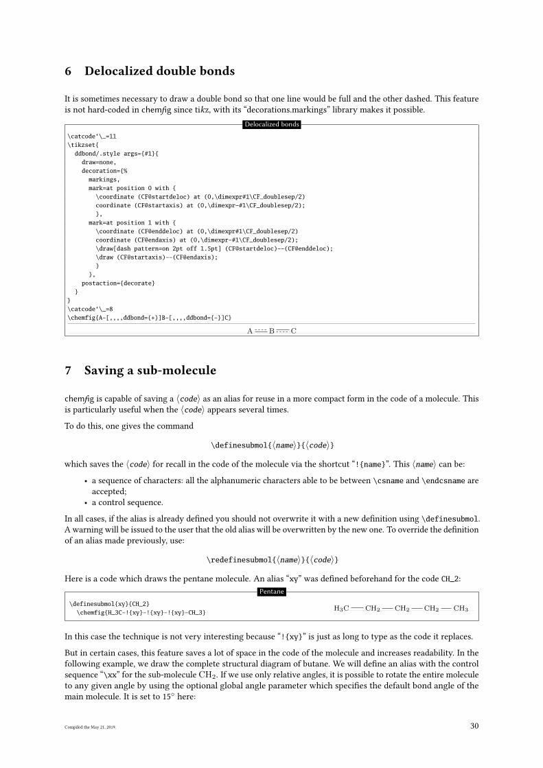
6 Delocalized double bonds
It is sometimes necessary to draw a double bond so that one line would be full and the other dashed. This feature
is not hard-coded in chemfig since tikz, with its “decorations.markings” library makes it possible.
Delocalized bonds
\catcode‘\_=11\tikzset{
ddbond/.style args={#1}{draw=none,decoration={%
markings,mark=at position 0 with {
\coordinate (CF@startdeloc) at (0,\dimexpr#1\CF_doublesep/2)coordinate (CF@startaxis) at (0,\dimexpr-#1\CF_doublesep/2);},
mark=at position 1 with {\coordinate (CF@enddeloc) at (0,\dimexpr#1\CF_doublesep/2)coordinate (CF@endaxis) at (0,\dimexpr-#1\CF_doublesep/2);\draw[dash pattern=on 2pt off 1.5pt] (CF@startdeloc)--(CF@enddeloc);\draw (CF@startaxis)--(CF@endaxis);}
},postaction={decorate}
}}\catcode‘\_=8\chemfig{A-[,,,,ddbond={+}]B-[,,,,ddbond={-}]C}
A B C
7 Saving a sub-molecule
chemfig is capable of saving a 〈code〉 as an alias for reuse in a more compact form in the code of a molecule. This
is particularly useful when the 〈code〉 appears several times.
To do this, one gives the command
\definesubmol{〈name〉}{〈code〉}
which saves the 〈code〉 for recall in the code of the molecule via the shortcut “!{name}”. This 〈name〉 can be:
• a sequence of characters: all the alphanumeric characters able to be between \csname and \endcsname are
accepted;
• a control sequence.
In all cases, if the alias is already de�ned you should not overwrite it with a new de�nition using \definesubmol.
A warning will be issued to the user that the old alias will be overwritten by the new one. To override the de�nition
of an alias made previously, use:
\redefinesubmol{〈name〉}{〈code〉}
Here is a code which draws the pentane molecule. An alias “xy” was de�ned beforehand for the code CH_2:
\definesubmol{xy}{CH_2}\chemfig{H_3C-!{xy}-!{xy}-!{xy}-CH_3}
H3C CH2 CH2 CH2 CH3
Pentane
In this case the technique is not very interesting because “!{xy}” is just as long to type as the code it replaces.
But in certain cases, this feature saves a lot of space in the code of the molecule and increases readability. In the
following example, we draw the complete structural diagram of butane. We will de�ne an alias with the control
sequence “\xx” for the sub-molecule CH2. If we use only relative angles, it is possible to rotate the entire molecule
to any given angle by using the optional global angle parameter which speci�es the default bond angle of the
main molecule. It is set to 15◦
here:
Compiled the May 21, 2019. 30
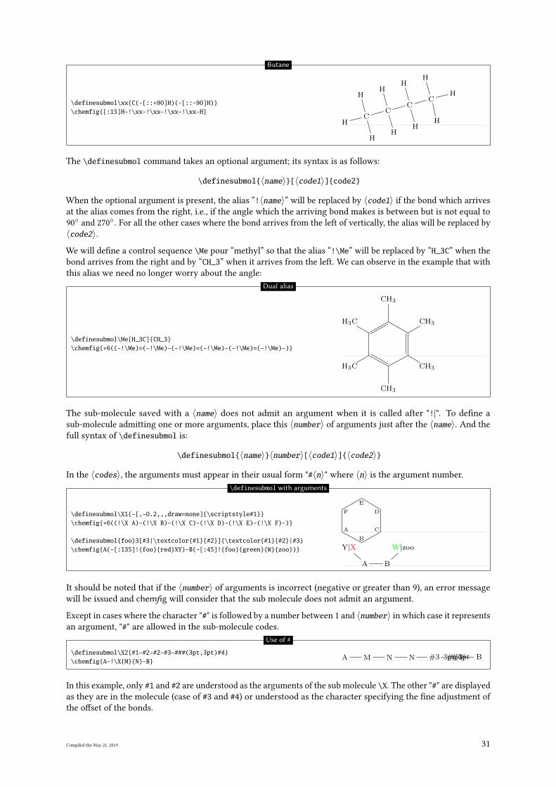
\definesubmol\xx{C(-[::+90]H)(-[::-90]H)}\chemfig{[:15]H-!\xx-!\xx-!\xx-!\xx-H}
HC
H
H
C
H
H
C
H
H
C
H
H
H
Butane
The \definesubmol command takes an optional argument; its syntax is as follows:
\definesubmol{〈name〉}[〈code1〉]{code2}
When the optional argument is present, the alias “!〈name〉” will be replaced by 〈code1〉 if the bond which arrives
at the alias comes from the right, i.e., if the angle which the arriving bond makes is between but is not equal to
90◦
and 270◦. For all the other cases where the bond arrives from the left of vertically, the alias will be replaced by
〈code2〉.
We will de�ne a control sequence \Me pour “methyl” so that the alias “!\Me” will be replaced by “H_3C” when the
bond arrives from the right and by “CH_3” when it arrives from the left. We can observe in the example that with
this alias we need no longer worry about the angle:
\definesubmol\Me[H_3C]{CH_3}\chemfig{*6((-!\Me)=(-!\Me)-(-!\Me)=(-!\Me)-(-!\Me)=(-!\Me)-)}
H3C
CH3
CH3
CH3
CH3
H3C
Dual alias
The sub-molecule saved with a 〈name〉 does not admit an argument when it is called after "!|". To de�ne a
sub-molecule admitting one or more arguments, place this 〈number〉 of arguments just after the 〈name〉. And the
full syntax of \definesubmol is:
\definesubmol{〈name〉}〈number〉[〈code1〉]{〈code2〉}
In the 〈codes〉, the arguments must appear in their usual form "#〈n〉" where 〈n〉 is the argument number.
\definesubmol\X1{-[,-0.2,,,draw=none]{\scriptstyle#1}}\chemfig{*6((!\X A)-(!\X B)-(!\X C)-(!\X D)-(!\X E)-(!\X F)-)}
\definesubmol{foo}3[#3|\textcolor{#1}{#2}]{\textcolor{#1}{#2}|#3}\chemfig{A(-[:135]!{foo}{red}XY)-B(-[:45]!{foo}{green}{W}{zoo})}
A
B
C
D
E
F
A
Y|X
B
W|zoo
\definesubmol with arguments
It should be noted that if the 〈number〉 of arguments is incorrect (negative or greater than 9), an error message
will be issued and chemfig will consider that the sub molecule does not admit an argument.
Except in cases where the character "#" is followed by a number between 1 and 〈number〉 in which case it represents
an argument, "#" are allowed in the sub-molecule codes.
\definesubmol\X2{#1-#2-#2-#3-###(3pt,3pt)#4}\chemfig{A-!\X{M}{N}-B}
A M N N #3 ###3pt, 3pt#4 B
Use of #
In this example, only #1 and #2 are understood as the arguments of the sub molecule \X. The other "#" are displayed
as they are in the molecule (case of #3 and #4) or understood as the character specifying the �ne adjustment of
the o�set of the bonds.
Compiled the May 21, 2019. 31
8 Decorations
8.1 Lewis diagrams
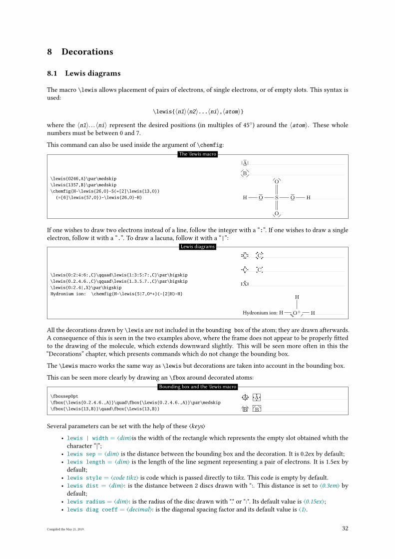
The macro \lewis allows placement of pairs of electrons, of single electrons, or of empty slots. This syntax is
used:
\lewis{〈n1〉〈n2〉...〈ni〉,〈atom〉}
where the 〈n1〉. . . 〈ni〉 represent the desired positions (in multiples of 45◦) around the 〈atom〉. These whole
numbers must be between 0 and 7.
This command can also be used inside the argument of \chemfig:
\lewis{0246,A}\par\medskip\lewis{1357,B}\par\medskip\chemfig{H-\lewis{26,O}-S(=[2]\lewis{13,O})
(=[6]\lewis{57,O})-\lewis{26,O}-H}
A
B
H O S
O
O
O H
The \lewis macro
If one wishes to draw two electrons instead of a line, follow the integer with a “:”. If one wishes to draw a single
electron, follow it with a “.”. To draw a lacuna, follow it with a “|”:
\lewis{0:2:4:6:,C}\qquad\lewis{1:3:5:7:,C}\par\bigskip\lewis{0.2.4.6.,C}\qquad\lewis{1.3.5.7.,C}\par\bigskip\lewis{0:2.4|,X}\par\bigskipHydronium ion: \chemfig{H-\lewis{5|7,O^+}(-[2]H)-H}
C C
C C
X
Hydronium ion: H O+
H
H
Lewis diagrams
All the decorations drawn by \lewis are not included in the bounding box of the atom; they are drawn afterwards.
A consequence of this is seen in the two examples above, where the frame does not appear to be properly �tted
to the drawing of the molecule, which extends downward slightly. This will be seen more often in this the
“Decorations” chapter, which presents commands which do not change the bounding box.
The \Lewis macro works the same way as \lewis but decorations are taken into account in the bounding box.
This can be seen more clearly by drawing an \fbox around decorated atoms:
\fboxsep0pt\fbox{\lewis{0.2.4.6.,A}}\quad\fbox{\Lewis{0.2.4.6.,A}}\par\medskip\fbox{\lewis{13,B}}\quad\fbox{\Lewis{13,B}}
A A
B B
Bounding box and the \lewis macro
Several parameters can be set with the help of these ⟨keys⟩
• lewis | width = ⟨dim⟩is the width of the rectangle which represents the empty slot obtained whith the
character “|”;
• lewis sep = ⟨dim⟩ is the distance between the bounding box and the decoration. It is 0.2ex by default;
• lewis length = ⟨dim⟩ is the length of the line segment representing a pair of electrons. It is 1.5ex by
default;
• lewis style = ⟨code tikz⟩ is code which is passed directly to tikz. This code is empty by default.
• lewis dist = ⟨dim⟩: is the distance between 2 discs drawn with ":. This distance is set to ⟨0.3em⟩ by
default;
• lewis radius = ⟨dim⟩: is the radius of the disc drawn with "." or ":". Its default value is ⟨0.15ex⟩;• lewis diag coeff = ⟨decimal⟩: is the diagonal spacing factor and its default value is ⟨1⟩.
Compiled the May 21, 2019. 32
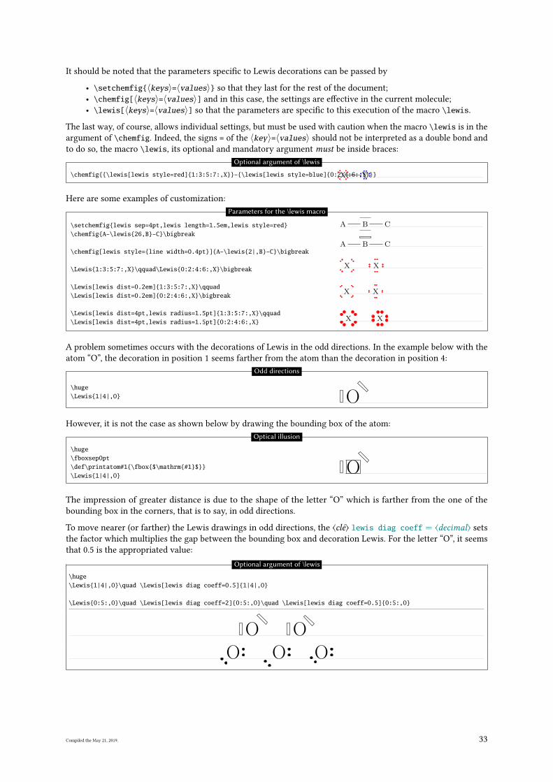
It should be noted that the parameters speci�c to Lewis decorations can be passed by
• \setchemfig{〈keys〉=〈values〉} so that they last for the rest of the document;
• \chemfig[〈keys〉=〈values〉] and in this case, the settings are e�ective in the current molecule;
• \lewis[〈keys〉=〈values〉] so that the parameters are speci�c to this execution of the macro \lewis.
The last way, of course, allows individual settings, but must be used with caution when the macro \lewis is in the
argument of \chemfig. Indeed, the signs = of the 〈key〉=〈values〉 should not be interpreted as a double bond and
to do so, the macro \lewis, its optional and mandatory argument must be inside braces:
\chemfig{{\lewis[lewis style=red]{1:3:5:7:,X}}-{\lewis[lewis style=blue]{0:2:4:6:,Y}}}X Y
Optional argument of \lewis
Here are some examples of customization:
\setchemfig{lewis sep=4pt,lewis length=1.5em,lewis style=red}\chemfig{A-\lewis{26,B}-C}\bigbreak
\chemfig[lewis style={line width=0.4pt}]{A-\lewis{2|,B}-C}\bigbreak
\Lewis{1:3:5:7:,X}\qquad\Lewis{0:2:4:6:,X}\bigbreak
\Lewis[lewis dist=0.2em]{1:3:5:7:,X}\qquad\Lewis[lewis dist=0.2em]{0:2:4:6:,X}\bigbreak
\Lewis[lewis dist=4pt,lewis radius=1.5pt]{1:3:5:7:,X}\qquad\Lewis[lewis dist=4pt,lewis radius=1.5pt]{0:2:4:6:,X}
A B C
A B C
X X
X X
X X
Parameters for the \lewis macro
A problem sometimes occurs with the decorations of Lewis in the odd directions. In the example below with the
atom “O”, the decoration in position 1 seems farther from the atom than the decoration in position 4:
\huge\Lewis{1|4|,O} O
Odd directions
However, it is not the case as shown below by drawing the bounding box of the atom:
\huge\fboxsep0pt\def\printatom#1{\fbox{$\mathrm{#1}$}}\Lewis{1|4|,O}
O
Optical illusion
The impression of greater distance is due to the shape of the letter “O” which is farther from the one of the
bounding box in the corners, that is to say, in odd directions.
To move nearer (or farther) the Lewis drawings in odd directions, the ⟨clé⟩ lewis diag coeff = ⟨decimal⟩ sets
the factor which multiplies the gap between the bounding box and decoration Lewis. For the letter “O”, it seems
that 0.5 is the appropriated value:
Optional argument of \lewis
\huge\Lewis{1|4|,O}\quad \Lewis[lewis diag coeff=0.5]{1|4|,O}
\Lewis{0:5:,O}\quad \Lewis[lewis diag coeff=2]{0:5:,O}\quad \Lewis[lewis diag coeff=0.5]{0:5:,O}
O OO O O
Compiled the May 21, 2019. 33
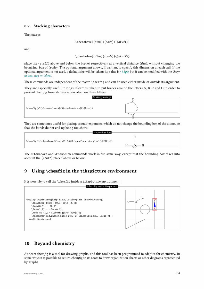
8.2 Stacking characters
The macros
\chemabove[〈dim〉]{〈code〉}{〈stuff〉}
and
\chembelow[〈dim〉]{〈code〉}{〈stuff〉}
place the 〈stuff〉 above and below the 〈code〉 respectively at a vertical distance 〈dim〉, without changing the
bounding box of 〈code〉. The optional argument allows, if written, to specify this dimension at each call. If the
optional argument is not used, a default size will be taken: its value is ⟨1.5pt⟩ but it can be modi�ed with the ⟨key⟩stack sep = ⟨dim⟩.
These commands are independent of the macro \chemfig and can be used either inside or outside its argument.
They are especially useful in rings, if care is taken to put braces around the letters A, B, C and D in order to
prevent chemfig from starting a new atom on these letters:
\chemfig{*5(-\chembelow{A}{B}--\chemabove{C}{D}--)}
AB
DC
Staking in rings
They are sometimes useful for placing pseudo-exponents which do not change the bounding box of the atoms, so
that the bonds do not end up being too short:
\chemfig{H-\chemabove{\lewis{5|7,O}}{\quad\scriptstyle+}(-[2]H)-H}
H+
O
H
H
Hydronium ion
The \Chemabove and \Chembelow commands work in the same way, except that the bounding box takes into
account the 〈stuff〉 placed above or below.
9 Using \chemfig in the tikzpicture environment
It is possible to call the \chemfig inside a tikzpicture environment:
\begin{tikzpicture}[help lines/.style={thin,draw=black!50}]\draw[help lines] (0,0) grid (4,4);\draw(0,0) -- (2,1);\draw(2,2) circle (0.5);\node at (1,3) {\chemfig{A=B-[:30]C}};\node[draw,red,anchor=base] at(3,2){\chemfig{X>[2,,,,blue]Y}};
\end{tikzpicture}
A B
C
X
Y
\chemfig inside tikzpicture
10 Beyond chemistry
At heart chemfig is a tool for drawing graphs, and this tool has been programmed to adapt it for chemistry. In
some ways it is possible to return chemfig to its roots to draw organization charts or other diagrams represented
by graphs.
Compiled the May 21, 2019. 34
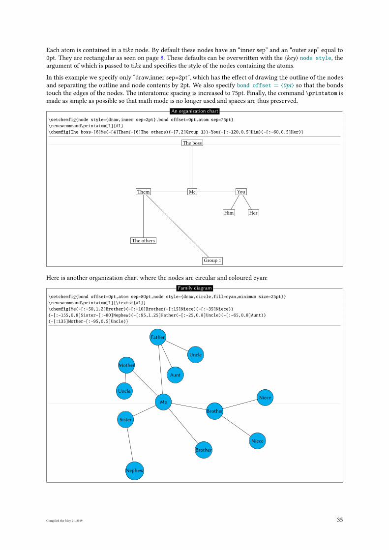
Each atom is contained in a tikz node. By default these nodes have an “inner sep” and an “outer sep” equal to
0pt. They are rectangular as seen on page 8. These defaults can be overwritten with the ⟨key⟩ node style, the
argument of which is passed to tikz and speci�es the style of the nodes containing the atoms.
In this example we specify only “draw,inner sep=2pt”, which has the e�ect of drawing the outline of the nodes
and separating the outline and node contents by 2pt. We also specify bond offset = ⟨0pt⟩ so that the bonds
touch the edges of the nodes. The interatomic spacing is increased to 75pt. Finally, the command \printatom is
made as simple as possible so that math mode is no longer used and spaces are thus preserved.
An organization chart
\setchemfig{node style={draw,inner sep=2pt},bond offset=0pt,atom sep=75pt}\renewcommand\printatom[1]{#1}\chemfig{The boss-[6]Me(-[4]Them(-[6]The others)(-[7,2]Group 1))-You(-[:-120,0.5]Him)(-[:-60,0.5]Her)}
The boss
MeThem
The others
Group 1
You
Him Her
Here is another organization chart where the nodes are circular and coloured cyan:
Family diagram
\setchemfig{bond offset=0pt,atom sep=80pt,node style={draw,circle,fill=cyan,minimum size=25pt}}\renewcommand\printatom[1]{\textsf{#1}}\chemfig{Me(-[:-50,1.2]Brother)(-[:-10]Brother(-[:15]Niece)(-[:-35]Niece))(-[:-155,0.8]Sister-[:-80]Nephew)(-[:95,1.25]Father(-[:-25,0.8]Uncle)(-[:-65,0.8]Aunt))(-[:135]Mother-[:-95,0.5]Uncle)}
Me
Brother
Brother
Niece
Niece
Sister
Nephew
Father
Uncle
Aunt
Mother
Uncle
Compiled the May 21, 2019. 35
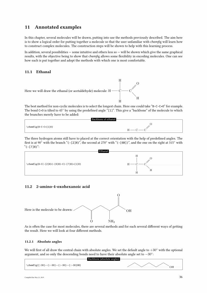
11 Annotated examples
In this chapter, several molecules will be drawn, putting into use the methods previously described. The aim here
is to show a logical order for putting together a molecule so that the user unfamiliar with chemfig will learn how
to construct complex molecules. The construction steps will be shown to help with this learning process.
In addition, several possibilities — some intuitive and others less so — will be shown which give the same graphical
results, with the objective being to show that chemfig allows some �exibility in encoding molecules. One can see
how each is put together and adopt the methods with which one is most comfortable.
11.1 Ethanal
Here we will draw the ethanal (or acetaldehyde) molecule: H C
H
H
C
H
O
The best method for non-cyclic molecules is to select the longest chain. Here one could take “H-C-C=0” for example.
The bond C=O is tilted to 45◦
by using the prede�ned angle “[1]”. This give a “backbone” of the molecule to which
the branches merely have to be added:
\chemfig{H-C-C=[1]O}H C C
O
Backbone of ethanal
The three hydrogen atoms still have to placed at the correct orientation with the help of prede�ned angles. The
�rst is at 90◦
with the branch “(-[2]H)”, the second at 270◦
with “(-[6H])”, and the one on the right at 315◦
with
“(-[7]H)”:
\chemfig{H-C(-[2]H)(-[6]H)-C(-[7]H)=[1]O} H C
H
H
C
H
O
Ethanal
11.2 2-amino-4-oxohexanoic acid
Here is the molecule to be drawn:
O NH2
O
OH
As is often the case for most molecules, there are several methods and for each several di�erent ways of getting
the result. Here we will look at four di�erent methods.
11.2.1 Absolute angles
We will �rst of all draw the central chain with absolute angles. We set the default angle to +30◦ with the optional
argument, and so only the descending bonds need to have their absolute angle set to −30◦:
\chemfig{[:30]--[:-30]--[:-30]--[:-30]OH}OH
Backbone (absolute angles)
Compiled the May 21, 2019. 36
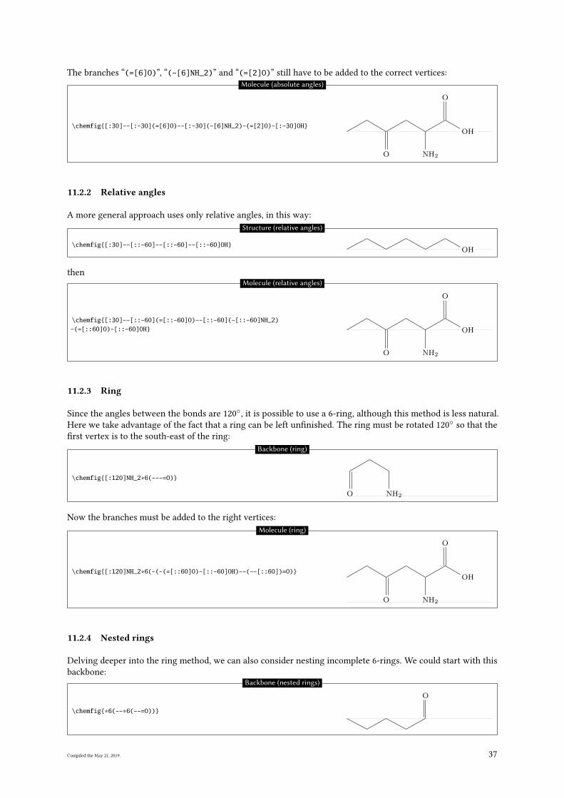
The branches “(=[6]O)”, “(-[6]NH_2)” and “(=[2]O)” still have to be added to the correct vertices:
\chemfig{[:30]--[:-30](=[6]O)--[:-30](-[6]NH_2)-(=[2]O)-[:-30]OH}
O NH2
O
OH
Molecule (absolute angles)
11.2.2 Relative angles
A more general approach uses only relative angles, in this way:
\chemfig{[:30]--[::-60]--[::-60]--[::-60]OH}OH
Structure (relative angles)
then
\chemfig{[:30]--[::-60](=[::-60]O)--[::-60](-[::-60]NH_2)-(=[::60]O)-[::-60]OH}
O NH2
O
OH
Molecule (relative angles)
11.2.3 Ring
Since the angles between the bonds are 120◦, it is possible to use a 6-ring, although this method is less natural.
Here we take advantage of the fact that a ring can be left un�nished. The ring must be rotated 120◦
so that the
�rst vertex is to the south-east of the ring:
\chemfig{[:120]NH_2*6(---=O)}
H2NO
Backbone (ring)
Now the branches must be added to the right vertices:
\chemfig{[:120]NH_2*6(-(-(=[::60]O)-[::-60]OH)--(--[::60])=O)}
H2N
O
OH
O
Molecule (ring)
11.2.4 Nested rings
Delving deeper into the ring method, we can also consider nesting incomplete 6-rings. We could start with this
backbone:
\chemfig{*6(--*6(--=O))}
O
Backbone (nested rings)
Compiled the May 21, 2019. 37
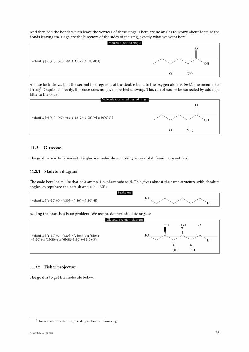
And then add the bonds which leave the vertices of these rings. There are no angles to worry about because the
bonds leaving the rings are the bisectors of the sides of the ring, exactly what we want here:
\chemfig{*6((-)-(=O)-*6(-(-NH_2)-(-OH)=O))}
O NH2
OH
O
Molecule (nested rings)
A close look shows that the second line segment of the double bond to the oxygen atom is inside the incomplete
6-ring9
Despite its brevity, this code does not give a perfect drawing. This can of course be corrected by adding a
little to the code:
\chemfig{*6((-)-(=O)-*6(-(-NH_2)-(-OH)(=[::60]O)))}
O NH2
OH
O
Molecule (corrected nested rings)
11.3 Glucose
The goal here is to represent the glucose molecule according to several di�erent conventions.
11.3.1 Skeleton diagram
The code here looks like that of 2-amino-4-oxohexanoic acid. This gives almost the same structure with absolute
angles, except here the default angle is −30◦:
\chemfig{[:-30]HO--[:30]--[:30]--[:30]-H}HO
H
Backbone
Adding the branches is no problem. We use prede�ned absolute angles:
\chemfig{[:-30]HO--[:30](<[2]OH)-(<:[6]OH)-[:30](<:[2]OH)-(<:[6]OH)-[:30](=[2]O)-H}
HO
OH
OH
OH
OH
O
H
Glucose, skeleton diagram
11.3.2 Fisher projection
The goal is to get the molecule below:
9This was also true for the preceding method with one ring.
Compiled the May 21, 2019. 38
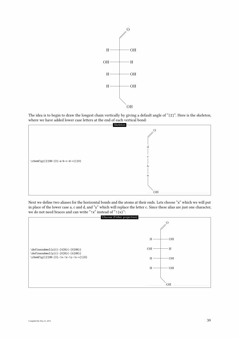
OH
H OH
H OH
HHO
H OH
O
The idea is to begin to draw the longest chain vertically by giving a default angle of “[2]”. Here is the skeleton,
where we have added lower case letters at the end of each vertical bond:
\chemfig{[2]OH-[3]-a-b-c-d-=[1]O}
OH
a
b
c
d
O
Skeleton
Next we de�ne two aliases for the horizontal bonds and the atoms at their ends. Lets choose “x” which we will put
in place of the lower case a, c and d, and “y” which will replace the letter c. Since these alias are just one character,
we do not need braces and can write “!x” instead of “!{x}”:
\definesubmol{x}{(-[4]H)(-[0]OH)}\definesubmol{y}{(-[0]H)(-[4]OH)}\chemfig{[2]OH-[3]-!x-!x-!y-!x-=[1]O}
OH
H OH
H OH
HHO
H OH
O
Glucose (Fisher projection)
Compiled the May 21, 2019. 39
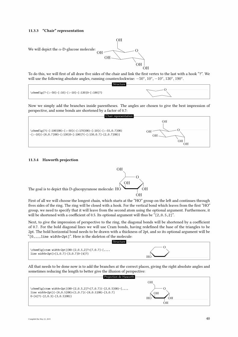
11.3.3 “Chair” representation
We will depict the α-D-glucose molecule:
HO
HO
OHOH
O
OH
To do this, we will �rst of all draw �ve sides of the chair and link the �rst vertex to the last with a hook “?”. We
will use the following absolute angles, running counterclockwise: −50◦, 10◦, −10◦, 130◦, 190◦.
\chemfig{?-[:-50]-[:10]-[:-10]-[:130]O-[:190]?}O
Structure
Now we simply add the branches inside parentheses. The angles are chosen to give the best impression of
perspective, and some bonds are shortened by a factor of 0.7:
\chemfig{?(-[:190]OH)-[:-50](-[:170]OH)-[:10](-[:-55,0.7]OH)-[:-10](-[6,0.7]OH)-[:130]O-[:190]?(-[:150,0.7]-[2,0.7]OH)}
HO
HO
OHOH
O
OH
Chair representation
11.3.4 Haworth projection
The goal is to depict this D-glucopyranose molecule: HO
OH
OH
OH
O
HO
First of all we will choose the longest chain, which starts at the “HO” group on the left and continues through
�ves sides of the ring. The ring will be closed with a hook. For the vertical bond which leaves from the �rst “HO”
group, we need to specify that it will leave from the second atom using the optional argument. Furthermore, it
will be shortened with a coe�cient of 0.5. Its optional argument will thus be “[2,0.5,2]”.
Next, to give the impression of perspective to the ring, the diagonal bonds will be shortened by a coe�cient
of 0.7. For the bold diagonal lines we will use Cram bonds, having rede�ned the base of the triangles to be
2pt. The bold horizontal bond needs to be drawn with a thickness of 2pt, and so its optional argument will be
“[0,,,,line width=2pt]”. Here is the skeleton of the molecule:
\chemfig[cram width=2pt]{HO-[2,0.5,2]?<[7,0.7]-[,,,,line width=2pt]>[1,0.7]-[3,0.7]O-[4]?}
HO
O
Structure
All that needs to be done now is to add the branches at the correct places, giving the right absolute angles and
sometimes reducing the length to better give the illusion of perspective:
\chemfig[cram width=2pt]{HO-[2,0.5,2]?<[7,0.7](-[2,0.5]OH)-[,,,,line width=2pt](-[6,0.5]OH)>[1,0.7](-[6,0.5]OH)-[3,0.7]O-[4]?(-[2,0.3]-[3,0.5]OH)}
HO
OH
OH
OH
O
HO
Projection de Haworth
Compiled the May 21, 2019. 40
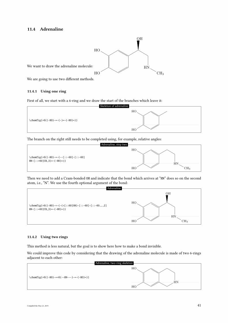
11.4 Adrenaline
We want to draw the adrenaline molecule:
OH
OH
NH
CH3
OH
We are going to use two di�erent methods.
11.4.1 Using one ring
First of all, we start with a 6-ring and we draw the start of the branches which leave it:
\chemfig{*6((-HO)-=-(-)=-(-HO)=)}
OH
OH
Skeleton of adrenaline
The branch on the right still needs to be completed using, for example, relative angles:
\chemfig{*6((-HO)-=-(--[::-60]-[::-60]HN-[::+60]CH_3)=-(-HO)=)}
OH
HN
CH3
OH
Adrenaline, step two
Then we need to add a Cram-bonded OH and indicate that the bond which arrives at “HN” does so on the second
atom, i.e., “N”. We use the fourth optional argument of the bond:
\chemfig{*6((-HO)-=-(-(<[::60]OH)-[::-60]-[::-60,,,2]HN-[::+60]CH_3)=-(-HO)=)}
OH
OH
NH
CH3
OH
Adrenaline
11.4.2 Using two rings
This method is less natural, but the goal is to show here how to make a bond invisible.
We could improve this code by considering that the drawing of the adrenaline molecule is made of two 6-rings
adjacent to each other:
\chemfig{*6((-HO)-=*6(--HN---)-=-(-HO)=)}
OH
HN
OH
Adrenaline, two-ring skeleton
Compiled the May 21, 2019. 41
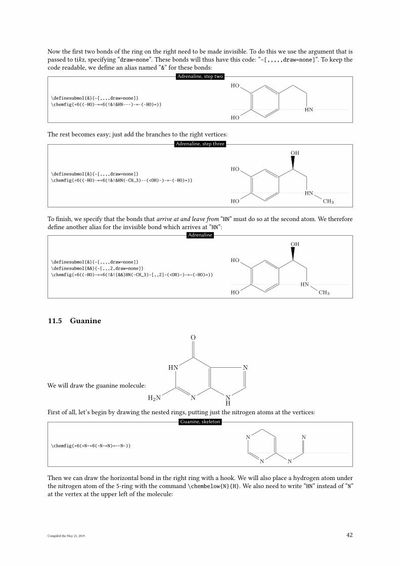
Now the �rst two bonds of the ring on the right need to be made invisible. To do this we use the argument that is
passed to tikz, specifying “draw=none”. These bonds will thus have this code: “-[,,,,,draw=none]”. To keep the
code readable, we de�ne an alias named “&” for these bonds:
\definesubmol{&}{-[,,,,draw=none]}\chemfig{*6((-HO)-=*6(!&!&HN---)-=-(-HO)=)}
OH
HN
OH
Adrenaline, step two
The rest becomes easy; just add the branches to the right vertices:
\definesubmol{&}{-[,,,,draw=none]}\chemfig{*6((-HO)-=*6(!&!&HN(-CH_3)--(<OH)-)-=-(-HO)=)}
OH
HN
CH3
OH
OH
Adrenaline, step three
To �nish, we specify that the bonds that arrive at and leave from “HN” must do so at the second atom. We therefore
de�ne another alias for the invisible bond which arrives at “HN”:
\definesubmol{&}{-[,,,,draw=none]}\definesubmol{&&}{-[,,,2,draw=none]}\chemfig{*6((-HO)-=*6(!&!{&&}HN(-CH_3)-[,,2]-(<OH)-)-=-(-HO)=)}
OH
NH
CH3
OH
OH
Adrenaline
11.5 Guanine
We will draw the guanine molecule:
NH2 N NH
N
O
NH
First of all, let’s begin by drawing the nested rings, putting just the nitrogen atoms at the vertices:
\chemfig{*6(=N-*6(-N-=N)=--N-)}
N N
NN
Guanine, skeleton
Then we can draw the horizontal bond in the right ring with a hook. We will also place a hydrogen atom under
the nitrogen atom of the 5-ring with the command \chembelow{N}{H}. We also need to write “HN” instead of “N”
at the vertex at the upper left of the molecule:
Compiled the May 21, 2019. 42
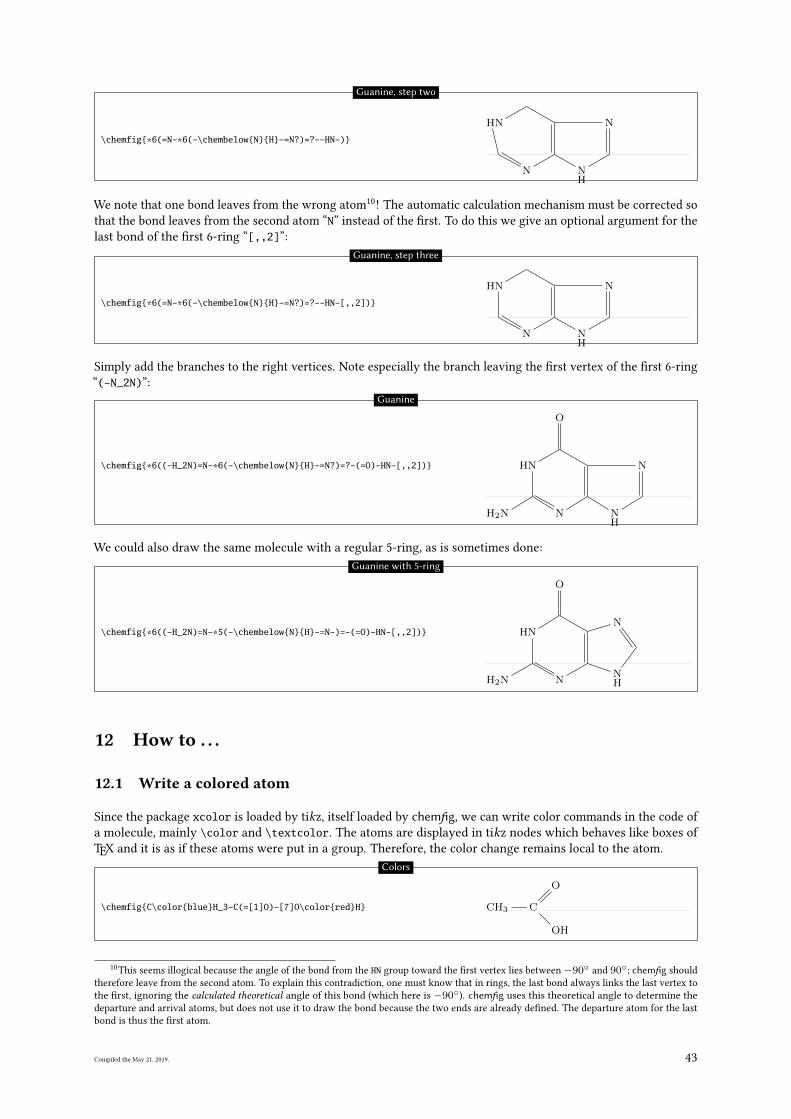
\chemfig{*6(=N-*6(-\chembelow{N}{H}-=N?)=?--HN-)}
N NH
NNH
Guanine, step two
We note that one bond leaves from the wrong atom10
! The automatic calculation mechanism must be corrected so
that the bond leaves from the second atom “N” instead of the �rst. To do this we give an optional argument for the
last bond of the �rst 6-ring “[,,2]”:
\chemfig{*6(=N-*6(-\chembelow{N}{H}-=N?)=?--HN-[,,2])}
N NH
NNH
Guanine, step three
Simply add the branches to the right vertices. Note especially the branch leaving the �rst vertex of the �rst 6-ring
“(-N_2N)”:
\chemfig{*6((-H_2N)=N-*6(-\chembelow{N}{H}-=N?)=?-(=O)-HN-[,,2])}
NH2 N NH
N
O
NH
Guanine
We could also draw the same molecule with a regular 5-ring, as is sometimes done:
\chemfig{*6((-H_2N)=N-*5(-\chembelow{N}{H}-=N-)=-(=O)-HN-[,,2])}
NH2 NNH
N
O
NH
Guanine with 5-ring
12 How to . . .
12.1 Write a colored atom
Since the package xcolor is loaded by tikz, itself loaded by chemfig, we can write color commands in the code of
a molecule, mainly \color and \textcolor. The atoms are displayed in tikz nodes which behaves like boxes of
TEX and it is as if these atoms were put in a group. Therefore, the color change remains local to the atom.
\chemfig{C\color{blue}H_3-C(=[1]O)-[7]O\color{red}H} CH3 C
O
OH
Colors
10This seems illogical because the angle of the bond from the HN group toward the �rst vertex lies between−90◦ and 90◦; chemfig should
therefore leave from the second atom. To explain this contradiction, one must know that in rings, the last bond always links the last vertex to
the �rst, ignoring the calculated theoretical angle of this bond (which here is −90◦). chemfig uses this theoretical angle to determine the
departure and arrival atoms, but does not use it to draw the bond because the two ends are already de�ned. The departure atom for the last
bond is thus the �rst atom.
Compiled the May 21, 2019. 43
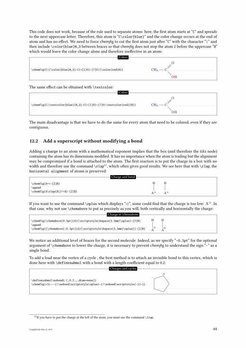
This code does not work, because of the rule used to separate atoms: here, the �rst atom starts at “C” and spreads
to the next uppercase letter. Therefore, this atom is “C\color{blue}” and the color change occurs at the end of
atom and has no e�ect. We need to force chemfig to cut the �rst atom just after “C” with the character “|” and
then include \color{blue}H_3 between braces so that chemfig does not stop the atom 2 before the uppercase “H”
which would leave the color change alone and therefore ine�ective in an atom:
\chemfig{C|{\color{blue}H_3}-C(=[1]O)-[7]O|{\color{red}H}} CH3 C
O
OH
Colors
The same e�ect can be obtained with \textcolor:
\chemfig{C|\textcolor{blue}{H_3}-C(=[1]O)-[7]O|\textcolor{red}{H}} CH3 C
O
OH
Colors
The main disadvantage is that we have to do the same for every atom that need to be colored, even if they are
contiguous.
12.2 Add a superscript without modifying a bond
Adding a charge to an atom with a mathematical exponent implies that the box (and therefore the tikz node)
containing the atom has its dimensions modi�ed. It has no importance when the atom is trailing but the alignment
may be compromised if a bond is attached to the atom. The �rst reaction is to put the charge in a box with no
width and therefore use the command \rlap11, which often gives good results. We see here that with \rlap, the
horizontal alignment of atoms is preserved:
\chemfig{A^+-[2]B}\qquad\chemfig{A\rlap{${}^+$}-[2]B} A+
B
A+
B
Charge and bond
If you want to use the command \oplus which displays “⊕”, some could �nd that the charge is too low: A⊕. In
that case, why not use \chemabove to put as precisely as you will, both vertically and horizontally the charge:
\chemfig{\chemabove[0.5pt]{A}{\scriptstyle\hspace{3.5mm}\oplus}-[2]B}\qquad\chemfig{{\chemabove[-0.5pt]{A}{\scriptstyle\hspace{3.5mm}\oplus}}-[2]B} ⊕
A
B
⊕A
B
Charge et \chemabove
We notice an additional level of braces for the second molecule. Indeed, as we specify “-0.5pt” for the optional
argument of \chemabove to lower the charge, it is necessary to prevent chemfig to understand the sign “-” as a
single bond.
To add a load near the vertex of a cycle , the best method is to attach an invisible bond to this vertex, which is
done here with \definesubmol with a bond with a length coe�cient equal to 0.2:
\definesubmol\nobond{-[,0.2,,,draw=none]}\chemfig{*5(---(!\nobond\scriptstyle\oplus)-(!\nobond\scriptstyle{-})-)}
⊕−
Charges and cycles
11If you have to put the charge at the left of the atom, you must use the command \llap.
Compiled the May 21, 2019. 44
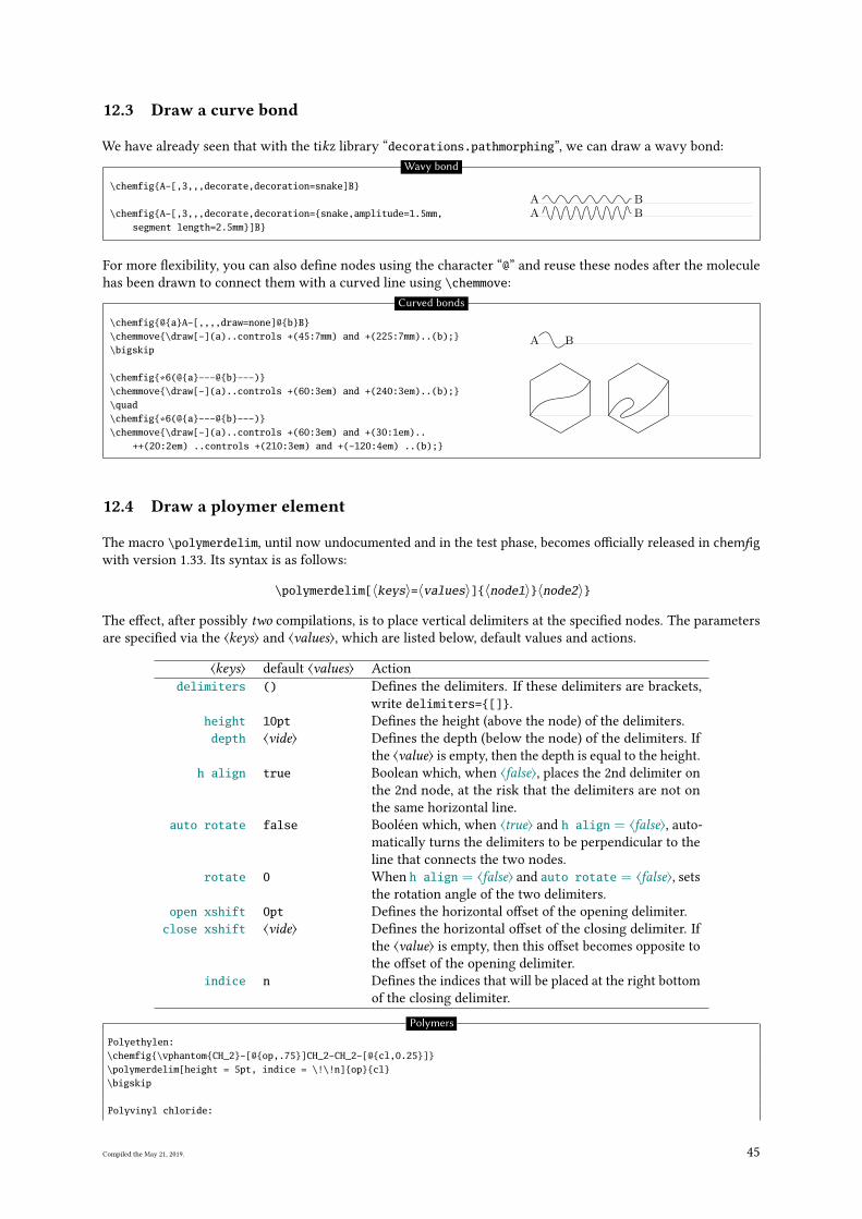
12.3 Draw a curve bond
We have already seen that with the tikz library “decorations.pathmorphing”, we can draw a wavy bond:
\chemfig{A-[,3,,,decorate,decoration=snake]B}
\chemfig{A-[,3,,,decorate,decoration={snake,amplitude=1.5mm,segment length=2.5mm}]B}
A BA B
Wavy bond
For more �exibility, you can also de�ne nodes using the character “@” and reuse these nodes after the molecule
has been drawn to connect them with a curved line using \chemmove:
\chemfig{@{a}A-[,,,,draw=none]@{b}B}\chemmove{\draw[-](a)..controls +(45:7mm) and +(225:7mm)..(b);}\bigskip
\chemfig{*6(@{a}---@{b}---)}\chemmove{\draw[-](a)..controls +(60:3em) and +(240:3em)..(b);}\quad\chemfig{*6(@{a}---@{b}---)}\chemmove{\draw[-](a)..controls +(60:3em) and +(30:1em)..
++(20:2em) ..controls +(210:3em) and +(-120:4em) ..(b);}
A B
Curved bonds
12.4 Draw a ploymer element
The macro \polymerdelim, until now undocumented and in the test phase, becomes o�cially released in chemfigwith version 1.33. Its syntax is as follows:
\polymerdelim[〈keys〉=〈values〉]{〈node1〉}〈node2〉}
The e�ect, after possibly two compilations, is to place vertical delimiters at the speci�ed nodes. The parameters
are speci�ed via the ⟨keys⟩ and ⟨values⟩, which are listed below, default values and actions.
⟨keys⟩ default ⟨values⟩ Action
delimiters () De�nes the delimiters. If these delimiters are brackets,
write delimiters={[]}.
height 10pt De�nes the height (above the node) of the delimiters.
depth ⟨vide⟩ De�nes the depth (below the node) of the delimiters. If
the ⟨value⟩ is empty, then the depth is equal to the height.
h align true Boolean which, when ⟨false⟩, places the 2nd delimiter on
the 2nd node, at the risk that the delimiters are not on
the same horizontal line.
auto rotate false Booléen which, when ⟨true⟩ and h align = ⟨false⟩, auto-
matically turns the delimiters to be perpendicular to the
line that connects the two nodes.
rotate 0 When h align = ⟨false⟩ and auto rotate = ⟨false⟩, sets
the rotation angle of the two delimiters.
open xshift 0pt De�nes the horizontal o�set of the opening delimiter.
close xshift ⟨vide⟩ De�nes the horizontal o�set of the closing delimiter. If
the ⟨value⟩ is empty, then this o�set becomes opposite to
the o�set of the opening delimiter.
indice n De�nes the indices that will be placed at the right bottom
of the closing delimiter.
Polymers
Polyethylen:\chemfig{\vphantom{CH_2}-[@{op,.75}]CH_2-CH_2-[@{cl,0.25}]}\polymerdelim[height = 5pt, indice = \!\!n]{op}{cl}\bigskip
Polyvinyl chloride:
Compiled the May 21, 2019. 45
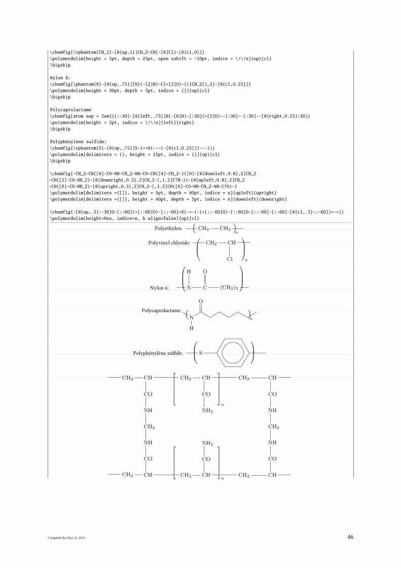
\chemfig{\vphantom{CH_2}-[@{op,1}]CH_2-CH(-[6]Cl)-[@{cl,0}]}\polymerdelim[height = 5pt, depth = 25pt, open xshift = -10pt, indice = \!\!n]{op}{cl}\bigskip
Nylon 6:\chemfig{\phantom{N}-[@{op,.75}]{N}(-[2]H)-C(=[2]O)-{(}CH_2{)_5}-[@{cl,0.25}]}\polymerdelim[height = 30pt, depth = 5pt, indice = {}]{op}{cl}\bigskip
Polycaprolactame\chemfig[atom sep = 2em]{[:-30]-[@{left,.75}]N(-[6]H)-[:30](=[2]O)--[:30]--[:30]--[@{right,0.25}:30]}\polymerdelim[height = 5pt, indice = \!\!n]{left}{right}\bigskip
Polyphénylène sulfide:\chemfig{\vphantom{S}-[@{op,.75}]S-(**6(---(-[@{cl,0.25}])---))}\polymerdelim[delimiters = (), height = 15pt, indice = {}]{op}{cl}\bigskip
\chemfig{-CH_2-CH([6]-CO-NH-CH_2-NH-CO-CH([4]-CH_2-)([0]-[@{downleft,0.8},2]CH_2-CH([2]-CO-NH_2)-[@{downright,0.3},2]CH_2-[,1.5]C?H-))-[@{upleft,0.8},2]CH_2-CH([6]-CO-NH_2)-[@{upright,0.3},2]CH_2-[,1.5]CH([6]-CO-NH-CH_2-NH-C?O)-}\polymerdelim[delimiters ={[]}, height = 5pt, depth = 40pt, indice = n]{upleft}{upright}\polymerdelim[delimiters ={[]}, height = 40pt, depth = 5pt, indice = n]{downleft}{downright}
\chemfig{-[@{op,.5}:-30]O-[::60](=[::60]O)-[::-60]*6(-=-(-(=[::-60]O)-[::60]O-[::-60]-[::60]-[@{cl,.5}::-60])=-=)}\polymerdelim[height=6ex, indice=n, h align=false]{op}{cl}
Polyethylen: CH2 CH2
( )n
Polyvinyl chloride: CH2 CH
Cl
n
Nylon 6: N
H
C
O
(CH2)5
Polycaprolactame
N
H
O( )n
Polyphénylène sul�de: S
CH2 CH
CO
NH
CH2
NH
CO
CHH2C CH2 CH
CO
NH2
CH2 CH
CH2 CH
CO
NH2
CH2 CH
CO
NH
CH2
NH
CO
n
n
Compiled the May 21, 2019. 46
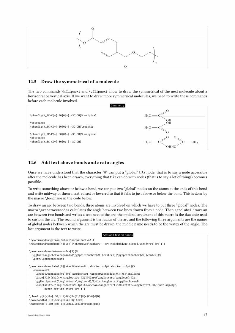
O
O
O
O
n
12.5 Draw the symmetrical of a molecule
The two commands \hflipnext and \vflipnext allow to draw the symmetrical of the next molecule about a
horizontal or vertical axis. If we want to draw more symmetrical molecules, we need to write these commands
before each molecule involved.
\chemfig{H_3C-C(=[:30]O)-[:-30]OH}% original
\vflipnext\chemfig{H_3C-C(=[:30]O)-[:-30]OH}\medskip
\chemfig{H_3C-C(=[:30]O)-[:-30]OH}% original\hflipnext\chemfig{H_3C-C(=[:30]O)-[:-30]OH}
H3C C
O
OH
H3C C
O
OH
H3C C
O
OH
H3CC
O
OH
Symmetry
12.6 Add text above bonds and arc to angles
Once we have understood that the character “@” can put a “global” tikz node, that is to say a node accessible
after the molecule has been drawn, everything that tikz can do with nodes (that is to say a lot of things) becomes
possible.
To write something above or below a bond, we can put two “global” nodes on the atoms at the ends of this bond
and write midway of them a text, raised or lowered so that it falls to just above or below the bond. This is done by
the macro \bondname in the code below.
To draw an arc between two bonds, three atoms are involved on which we have to put three “global” nodes. The
macro \arcbetweennodes calculates the angle between two lines drawn from a node. Then \arclabel draws an
arc between two bonds and writes a text next to the arc: the optional argument of this macro is the tikz code used
to custom the arc. The second argument is the radius of the arc and the following three arguments are the names
of global nodes between which the arc must be drawn, the middle name needs to be the vertex of the angle. The
last argument is the text to write.
Arcs and text on bonds
\newcommand\angstrom{\mbox{\normalfont\AA}}\newcommand\namebond[4][5pt]{\chemmove{\path(#2)--(#3)node[midway,sloped,yshift=#1]{#4};}}
\newcommand\arcbetweennodes[3]{%\pgfmathanglebetweenpoints{\pgfpointanchor{#1}{center}}{\pgfpointanchor{#2}{center}}%\let#3\pgfmathresult}
\newcommand\arclabel[6][stealth-stealth,shorten <=1pt,shorten >=1pt]{%\chemmove{%
\arcbetweennodes{#4}{#3}\anglestart \arcbetweennodes{#4}{#5}\angleend\draw[#1]([shift=(\anglestart:#2)]#4)arc(\anglestart:\angleend:#2);\pgfmathparse{(\anglestart+\angleend)/2}\let\anglestart\pgfmathresult\node[shift=(\anglestart:#2+1pt)#4,anchor=\anglestart+180,rotate=\anglestart+90,inner sep=0pt,
outer sep=0pt]at(#4){#6};}}
\chemfig{@{a}A=[:30,1.5]@{b}B-[7,2]@{c}C-@{d}D}\namebond{a}{b}{\scriptsize My text}\namebond[-3.5pt]{b}{c}{\small\color{red}$\pi$}
Compiled the May 21, 2019. 47
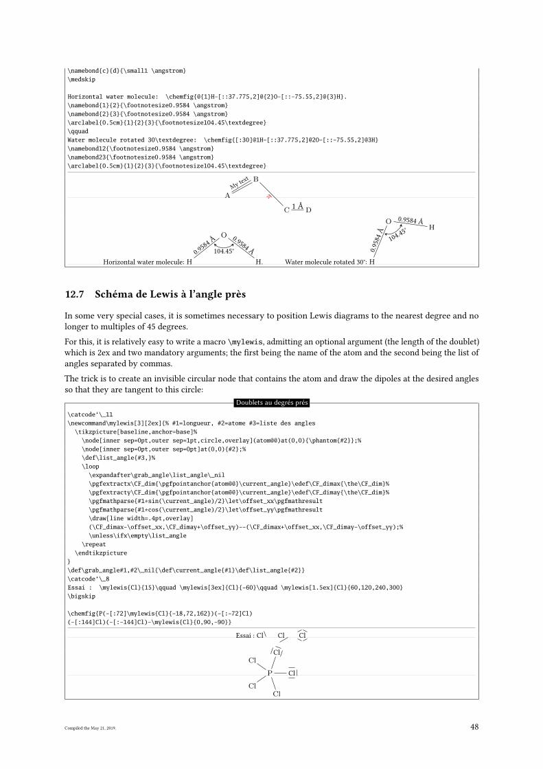
\namebond{c}{d}{\small1 \angstrom}\medskip
Horizontal water molecule: \chemfig{@{1}H-[::37.775,2]@{2}O-[::-75.55,2]@{3}H}.\namebond{1}{2}{\footnotesize0.9584 \angstrom}\namebond{2}{3}{\footnotesize0.9584 \angstrom}\arclabel{0.5cm}{1}{2}{3}{\footnotesize104.45\textdegree}\qquadWater molecule rotated 30\textdegree: \chemfig{[:30]@1H-[::37.775,2]@2O-[::-75.55,2]@3H}\namebond12{\footnotesize0.9584 \angstrom}\namebond23{\footnotesize0.9584 \angstrom}\arclabel{0.5cm}{1}{2}{3}{\footnotesize104.45\textdegree}
A
B
C D
My
text
π
1 Å
Horizontal water molecule: H
O
H.
0.9
584
Å0.9
584
Å104.45°
Water molecule rotated 30°: H
OH
0.9
584
Å
0.9584 Å
104.4
5°
12.7 Schéma de Lewis à l’angle près
In some very special cases, it is sometimes necessary to position Lewis diagrams to the nearest degree and no
longer to multiples of 45 degrees.
For this, it is relatively easy to write a macro \mylewis, admitting an optional argument (the length of the doublet)
which is 2ex and two mandatory arguments; the �rst being the name of the atom and the second being the list of
angles separated by commas.
The trick is to create an invisible circular node that contains the atom and draw the dipoles at the desired angles
so that they are tangent to this circle:
Doublets au degrés prés
\catcode‘\_11\newcommand\mylewis[3][2ex]{% #1=longueur, #2=atome #3=liste des angles
\tikzpicture[baseline,anchor=base]%\node[inner sep=0pt,outer sep=1pt,circle,overlay](atom@@)at(0,0){\phantom{#2}};%\node[inner sep=0pt,outer sep=0pt]at(0,0){#2};%\def\list_angle{#3,}%\loop
\expandafter\grab_angle\list_angle\_nil\pgfextractx\CF_dim{\pgfpointanchor{atom@@}\current_angle}\edef\CF_dimax{\the\CF_dim}%\pgfextracty\CF_dim{\pgfpointanchor{atom@@}\current_angle}\edef\CF_dimay{\the\CF_dim}%\pgfmathparse{#1*sin(\current_angle)/2}\let\offset_xx\pgfmathresult\pgfmathparse{#1*cos(\current_angle)/2}\let\offset_yy\pgfmathresult\draw[line width=.4pt,overlay](\CF_dimax-\offset_xx,\CF_dimay+\offset_yy)--(\CF_dimax+\offset_xx,\CF_dimay-\offset_yy);%\unless\ifx\empty\list_angle
\repeat\endtikzpicture
}\def\grab_angle#1,#2\_nil{\def\current_angle{#1}\def\list_angle{#2}}\catcode‘\_8Essai : \mylewis{Cl}{15}\qquad \mylewis[3ex]{Cl}{-60}\qquad \mylewis[1.5ex]{Cl}{60,120,240,300}\bigskip
\chemfig{P(-[:72]\mylewis{Cl}{-18,72,162})(-[:-72]Cl)(-[:144]Cl)(-[:-144]Cl)-\mylewis{Cl}{0,90,-90}}
Essai : Cl Cl Cl
P
Cl
Cl
Cl
Cl
Cl
Compiled the May 21, 2019. 48
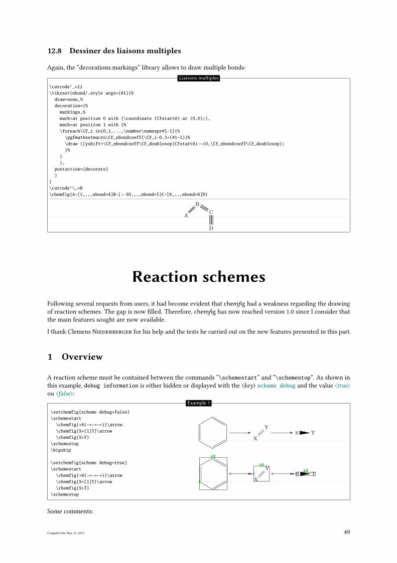
12.8 Dessiner des liaisons multiples
Again, the “decorations.markings” library allows to draw multiple bonds:
Liaisons multiples
\catcode‘_=11\tikzset{nbond/.style args={#1}{%
draw=none,%decoration={%
markings,%mark=at position 0 with {\coordinate (CFstart@) at (0,0);},mark=at position 1 with {%\foreach\CF_i in{0,1,...,\number\numexpr#1-1}{%
\pgfmathsetmacro\CF_nbondcoeff{\CF_i-0.5*(#1-1)}%\draw ([yshift=\CF_nbondcoeff\CF_doublesep]CFstart@)--(0,\CF_nbondcoeff\CF_doublesep);}%
}},
postaction={decorate}}
}\catcode‘\_=8\chemfig{A-[1,,,,nbond=4]B-[:-30,,,,nbond=5]C-[6,,,,nbond=6]D}
A
B
C
D
Reaction schemesFollowing several requests from users, it had become evident that chemfig had a weakness regarding the drawing
of reaction schemes. The gap is now �lled. Therefore, chemfig has now reached version 1.0 since I consider that
the main features sought are now available.
I thank Clemens Niederberger for his help and the tests he carried out on the new features presented in this part.
1 Overview
A reaction scheme must be contained between the commands “\schemestart” and “\schemestop”. As shown in
this example, debug information is either hidden or displayed with the ⟨key⟩ scheme debug and the value ⟨true⟩ou ⟨false⟩:
\setchemfig{scheme debug=false}\schemestart
\chemfig{*6(-=-=-=)}\arrow\chemfig{X=[1]Y}\arrow\chemfig{S>T}
\schemestop\bigskip
\setchemfig{scheme debug=true}\schemestart
\chemfig{*6(-=-=-=)}\arrow\chemfig{X=[1]Y}\arrow\chemfig{S>T}
\schemestop
X
YS T
c1
X
Yc2
S Tc3
Example 1
Some comments:
Compiled the May 21, 2019. 49
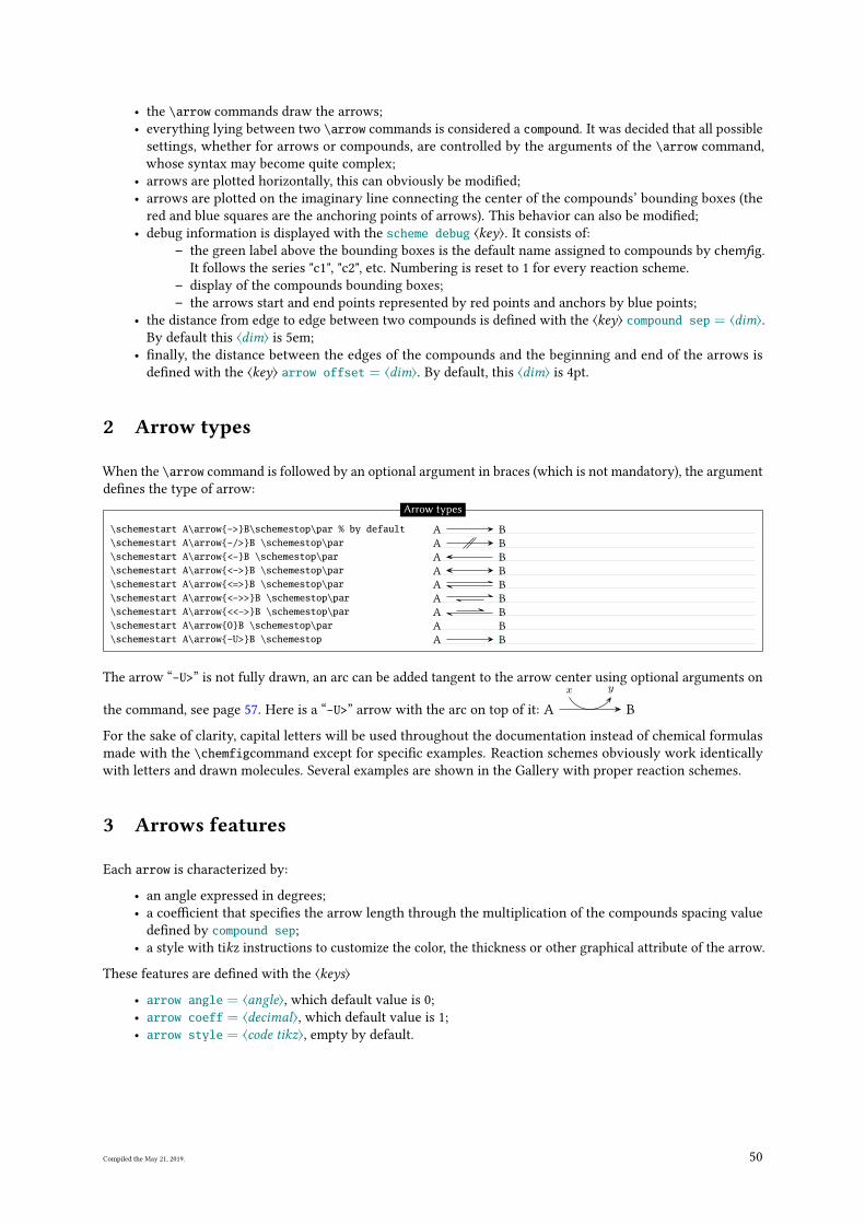
• the \arrow commands draw the arrows;
• everything lying between two \arrow commands is considered a compound. It was decided that all possible
settings, whether for arrows or compounds, are controlled by the arguments of the \arrow command,
whose syntax may become quite complex;
• arrows are plotted horizontally, this can obviously be modi�ed;
• arrows are plotted on the imaginary line connecting the center of the compounds’ bounding boxes (the
red and blue squares are the anchoring points of arrows). This behavior can also be modi�ed;
• debug information is displayed with the scheme debug ⟨key⟩. It consists of:
– the green label above the bounding boxes is the default name assigned to compounds by chemfig.
It follows the series "c1", "c2", etc. Numbering is reset to 1 for every reaction scheme.
– display of the compounds bounding boxes;
– the arrows start and end points represented by red points and anchors by blue points;
• the distance from edge to edge between two compounds is de�ned with the ⟨key⟩ compound sep = ⟨dim⟩.
By default this ⟨dim⟩ is 5em;
• �nally, the distance between the edges of the compounds and the beginning and end of the arrows is
de�ned with the ⟨key⟩ arrow offset = ⟨dim⟩. By default, this ⟨dim⟩ is 4pt.
2 Arrow types
When the \arrow command is followed by an optional argument in braces (which is not mandatory), the argument
de�nes the type of arrow:
\schemestart A\arrow{->}B\schemestop\par % by default\schemestart A\arrow{-/>}B \schemestop\par\schemestart A\arrow{<-}B \schemestop\par\schemestart A\arrow{<->}B \schemestop\par\schemestart A\arrow{<=>}B \schemestop\par\schemestart A\arrow{<->>}B \schemestop\par\schemestart A\arrow{<<->}B \schemestop\par\schemestart A\arrow{0}B \schemestop\par\schemestart A\arrow{-U>}B \schemestop
A B
A B
A B
A B
A B
A B
A B
A B
A B
Arrow types
The arrow “-U>” is not fully drawn, an arc can be added tangent to the arrow center using optional arguments on
the command, see page 57. Here is a “-U>” arrow with the arc on top of it: A
x y
B
For the sake of clarity, capital letters will be used throughout the documentation instead of chemical formulas
made with the \chemfigcommand except for speci�c examples. Reaction schemes obviously work identically
with letters and drawn molecules. Several examples are shown in the Gallery with proper reaction schemes.
3 Arrows features
Each arrow is characterized by:
• an angle expressed in degrees;
• a coe�cient that speci�es the arrow length through the multiplication of the compounds spacing value
de�ned by compound sep;
• a style with tikz instructions to customize the color, the thickness or other graphical attribute of the arrow.
These features are de�ned with the ⟨keys⟩
• arrow angle = ⟨angle⟩, which default value is 0;
• arrow coeff = ⟨decimal⟩, which default value is 1;
• arrow style = ⟨code tikz⟩, empty by default.
Compiled the May 21, 2019. 50
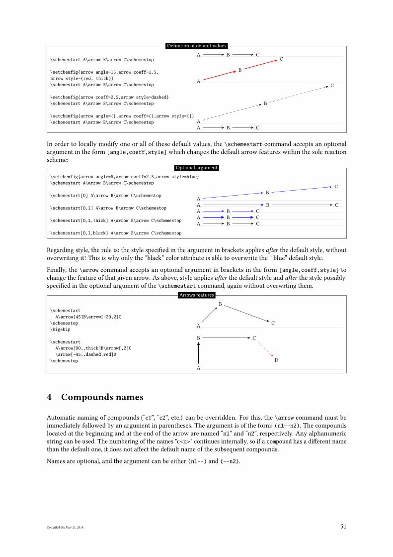
\schemestart A\arrow B\arrow C\schemestop
\setchemfig{arrow angle=15,arrow coeff=1.5,arrow style={red, thick}}\schemestart A\arrow B\arrow C\schemestop
\setchemfig{arrow coeff=2.5,arrow style=dashed}\schemestart A\arrow B\arrow C\schemestop
\setchemfig{arrow angle={},arrow coeff={},arrow style={}}\schemestart A\arrow B\arrow C\schemestop
A B C
A
B
C
A
B
C
A B C
Definition of default values
In order to locally modify one or all of these default values, the \schemestart command accepts an optional
argument in the form [angle,coeff,style] which changes the default arrow features within the sole reaction
scheme:
\setchemfig{arrow angle=5,arrow coeff=2.5,arrow style=blue}\schemestart A\arrow B\arrow C\schemestop
\schemestart[0] A\arrow B\arrow C\schemestop
\schemestart[0,1] A\arrow B\arrow C\schemestop
\schemestart[0,1,thick] A\arrow B\arrow C\schemestop
\schemestart[0,1,black] A\arrow B\arrow C\schemestop
A
B
C
A B C
A B C
A B C
A B C
Optional argument
Regarding style, the rule is: the style speci�ed in the argument in brackets applies after the default style, without
overwriting it! This is why only the “black” color attribute is able to overwrite the “ blue” default style.
Finally, the \arrow command accepts an optional argument in brackets in the form [angle,coeff,style] to
change the feature of that given arrow. As above, style applies after the default style and after the style possibly-
speci�ed in the optional argument of the \schemestart command, again without overwrting them.
\schemestartA\arrow[45]B\arrow[-20,2]C
\schemestop\bigskip
\schemestartA\arrow[90,,thick]B\arrow[,2]C\arrow[-45,,dashed,red]D
\schemestop
A
B
C
A
B C
D
Arrows features
4 Compounds names
Automatic naming of compounds (“c1”, “c2”, etc.) can be overridden. For this, the \arrow command must be
immediately followed by an argument in parentheses. The argument is of the form: (n1--n2). The compounds
located at the beginning and at the end of the arrow are named “n1” and “n2”, respectively. Any alphanumeric
string can be used. The numbering of the names "c<n>" continues internally, so if a compound has a di�erent name
than the default one, it does not a�ect the default name of the subsequent compounds.
Names are optional, and the argument can be either (n1--) and (--n2).
Compiled the May 21, 2019. 51
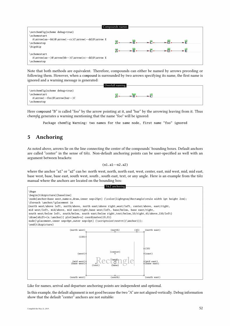
\setchemfig{scheme debug=true}\schemestart
A\arrow(aa--bb)B\arrow(--cc)C\arrow(--dd)D\arrow E\schemestop\bigskip
\schemestartA\arrow(aa--)B\arrow(bb--)C\arrow(cc--dd)D\arrow E
\schemestop
A
aaB
bbC
ccD
ddE
c5
A
aaB
bbC
ccD
ddE
c5
Compounds names
Note that both methods are equivalent. Therefore, compounds can either be named by arrows preceding or
following them. However, when a compound is surrounded by two arrows specifying its name, the �rst name is
ignored and a warning message is generated:
\setchemfig{scheme debug=true}\schemestart
A\arrow(--foo)B\arrow(bar--)C\schemestop
A
c1B
barC
c3
Overfull naming
Here compound “B” is called “foo” by the arrow pointing at it, and “bar” by the arrowing leaving from it. Thus
chemfig generates a warning mentioning that the name "foo" will be ignored:
Package chemfig Warning: two names for the same node, first name "foo" ignored
5 Anchoring
As noted above, arrows lie on the line connecting the center of the compounds’ bounding boxes. Default anchors
are called “center” in the sense of tikz. Non-default anchoring points can be user-speci�ed as well with an
argument between brackets:
(n1.a1--n2.a2)
where the anchor “a1” or “a2” can be: north west, north, north east, west, center, east, mid west, mid, mid east,
base west, base, base east, south west, south , south east, text, or any angle. Here is an example from the tikz
manual where the anchors are located on the bounding box:
TikZ anchoring
\Huge\begin{tikzpicture}[baseline]\node[anchor=base west,name=x,draw,inner sep=25pt] {\color{lightgray}Rectangle\vrule width 1pt height 2cm};\foreach \anchor/\placement in{north west/above left, north/above, north east/above right,west/left, center/above, east/right,mid west/left, mid/above, mid east/right,base west/left, base/below, base east/right,south west/below left, south/below, south east/below right,text/below,10/right,45/above,150/left}\draw[shift=(x.\anchor)] plot[mark=x] coordinates{(0,0)}node[\placement,inner sep=0pt,outer sep=2pt] {\scriptsize\texttt{(\anchor)}};\end{tikzpicture}
Rectangle
(north west) (north) (north east)
(west)(center)
(east)
(mid west)(mid)
(mid east)(base west)
(base)(base east)
(south west) (south) (south east)
(text)
(10)
(45)
(150)
Like for names, arrival and departure anchoring points are independent and optional.
In this example, the default alignment is not good because the two “A” are not aligned vertically. Debug information
show that the default “center” anchors are not suitable:
Compiled the May 21, 2019. 52
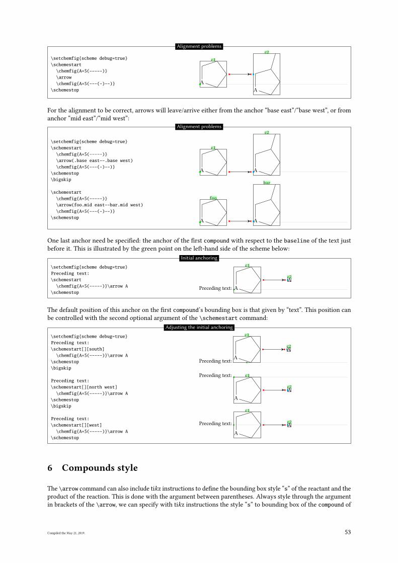
\setchemfig{scheme debug=true}\schemestart
\chemfig{A*5(-----)}\arrow\chemfig{A*5(---(-)--)}
\schemestop
A
c1
A
c2Alignment problems
For the alignment to be correct, arrows will leave/arrive either from the anchor “base east”/“base west”, or from
anchor “mid east”/“mid west”:
\setchemfig{scheme debug=true}\schemestart
\chemfig{A*5(-----)}\arrow(.base east--.base west)\chemfig{A*5(---(-)--)}
\schemestop\bigskip
\schemestart\chemfig{A*5(-----)}\arrow(foo.mid east--bar.mid west)\chemfig{A*5(---(-)--)}
\schemestop
A
c1
A
c2
A
foo
A
bar
Alignment problems
One last anchor need be speci�ed: the anchor of the �rst compound with respect to the baseline of the text just
before it. This is illustrated by the green point on the left-hand side of the scheme below:
\setchemfig{scheme debug=true}Preceding text:\schemestart
\chemfig{A*5(-----)}\arrow A\schemestop
Preceding text: A
c1
A
c2
Initial anchoring
The default position of this anchor on the �rst compound’s bounding box is that given by “text”. This position can
be controlled with the second optional argument of the \schemestart command:
\setchemfig{scheme debug=true}Preceding text:\schemestart[][south]
\chemfig{A*5(-----)}\arrow A\schemestop\bigskip
Preceding text:\schemestart[][north west]
\chemfig{A*5(-----)}\arrow A\schemestop\bigskip
Preceding text:\schemestart[][west]
\chemfig{A*5(-----)}\arrow A\schemestop
Preceding text:
A
c1
A
c2
Preceding text:
A
c1
A
c2
Preceding text:
A
c1
A
c2
Adjusting the initial anchoring
6 Compounds style
The \arrow command can also include tikz instructions to de�ne the bounding box style “s” of the reactant and the
product of the reaction. This is done with the argument between parentheses. Always style through the argument
in brackets of the \arrow, we can specify with tikz instructions the style “s” to bounding box of the compound of
Compiled the May 21, 2019. 53
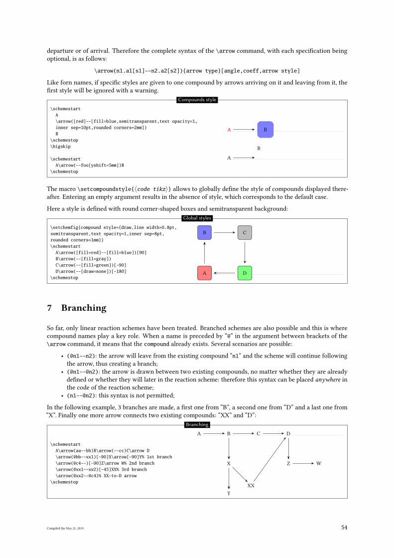
departure or of arrival. Therefore the complete syntax of the \arrow command, with each speci�cation being
optional, is as follows:
\arrow(n1.a1[s1]--n2.a2[s2]){arrow type}[angle,coeff,arrow style]
Like forn names, if speci�c styles are given to one compound by arrows arriving on it and leaving from it, the
�rst style will be ignored with a warning.
\schemestartA\arrow([red]--[fill=blue,semitransparent,text opacity=1,inner sep=10pt,rounded corners=2mm])B
\schemestop\bigskip
\schemestartA\arrow(--foo[yshift=5mm])B
\schemestop
A B
A
B
Compounds style
The macro \setcompoundstyle{〈code tikz〉} allows to globally de�ne the style of compounds displayed there-
after. Entering an empty argument results in the absence of style, which corresponds to the default case.
Here a style is de�ned with round corner-shaped boxes and semitransparent background:
\setchemfig{compound style={draw,line width=0.8pt,semitransparent,text opacity=1,inner sep=8pt,rounded corners=1mm}}\schemestart
A\arrow([fill=red]--[fill=blue])[90]B\arrow(--[fill=gray])C\arrow(--[fill=green])[-90]D\arrow(--[draw=none])[-180]
\schemestopA
B C
D
Global styles
7 Branching
So far, only linear reaction schemes have been treated. Branched schemes are also possible and this is where
compound names play a key role. When a name is preceded by “@” in the argument between brackets of the
\arrow command, it means that the compound already exists. Several scenarios are possible:
• (@n1--n2): the arrow will leave from the existing compound “n1” and the scheme will continue following
the arrow, thus creating a branch;
• (@n1--@n2): the arrow is drawn between two existing compounds, no matter whether they are already
de�ned or whether they will later in the reaction scheme: therefore this syntax can be placed anywhere in
the code of the reaction scheme;
• (n1--@n2): this syntax is not permitted;
In the following example, 3 branches are made, a �rst one from “B”, a second one from “D” and a last one from
“X”. Finally one more arrow connects two existing compounds: “XX” and “D”:
\schemestartA\arrow(aa--bb)B\arrow(--cc)C\arrow D\arrow(@bb--xx1)[-90]X\arrow[-90]Y% 1st branch\arrow(@c4--)[-90]Z\arrow W% 2nd branch\arrow(@xx1--xx2)[-45]XX% 3rd branch\arrow(@xx2--@c4)% XX-to-D arrow
\schemestop
A B C D
X
Y
Z W
XX
Branching
Compiled the May 21, 2019. 54
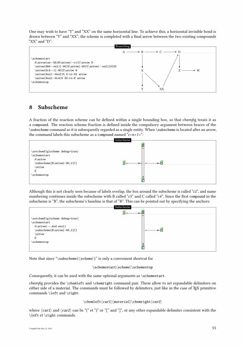
One may wish to have “Y” and “XX” on the same horizontal line. To achieve this, a horizontal invisible bond is
drawn between “Y” and “XX”; the scheme is completed with a �nal arrow between the two existing compounds
“XX” and “D”:
\schemestartA\arrow(aa--bb)B\arrow(--cc)C\arrow D\arrow(@bb--xx1)[-90]X\arrow[-90]Y\arrow(--xx2){0}XX\arrow(@c4--)[-90]Z\arrow W\arrow(@xx1--@xx2)% X-to-XX arrow\arrow(@xx2--@c4)% XX-to-D arrow
\schemestop
A B C D
X
Y XX
Z W
Branching
8 Subscheme
A fraction of the reaction scheme can be de�ned within a single bounding box, so that chemfig treats it as
a compound. The reaction scheme fraction is de�ned inside the compulsory argument between braces of the
\subscheme command so it is subsequently regarded as a single entity. When \subscheme is located after an arrow,
the command labels this subscheme as a compound named “c<n+1>”:
\setchemfig{scheme debug=true}\schemestart
A\arrow\subscheme{B\arrow[-90,2]C}\arrowD
\schemestop
A
c1
B
c3
C
c4
c2
D
c5
Subscheme
Although this is not clearly seen because of labels overlap, the box around the subscheme is called “c2”, and name
numbering continues inside the subscheme with B called “c3” and C called “c4”. Since the �rst compound in the
subscheme is “B”, the subscheme’s baseline is that of “B”. This can be pointed out by specifying the anchors:
\setchemfig{scheme debug=true}\schemestart
A\arrow(--.mid west)\subscheme{B\arrow[-90,2]C}\arrowD
\schemestop
A
c1B
c3
C
c4
c2
D
c5
Subscheme
Note that since “\subscheme{〈scheme〉}” is only a convenient shortcut for
\schemestart〈scheme〉\schemestop
Consequently, it can be used with the same optional arguments as \schemestart.
chemfig provides the \chemleft and \chemright command pair. These allow to set expandable delimiters on
either side of a material. The commands must be followed by delimiters, just like in the case of TEX primitive
commands \left and \right:
\chemleft〈car1〉〈material〉\chemright〈car2〉
where 〈car1〉 and 〈car2〉 can be “(” et “)” or “[” and “]”, or any other expandable delimiter consistent with the
\left et \right commands.
Compiled the May 21, 2019. 55
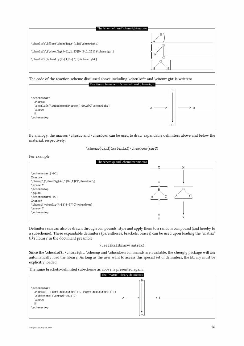
\chemleft\lfloor\chemfig{A-[1]B}\chemright)
\chemleft\{\chemfig{A-[1,1.25]B-[6,1.25]C}\chemright|
\chemleft[\chemfig{H-[1]O-[7]H}\chemright]
⌊A
B)
A
B
C
∣∣∣∣∣∣∣∣[H
O
H
]
The \chemle� and \chemrightmacros
The code of the reaction scheme discussed above including \chemleft and \chemright is written:
\schemestartA\arrow\chemleft[\subscheme{B\arrow[-90,2]C}\chemright]\arrowD
\schemestop
A
B
C
D
Reaction scheme with \chemle� and \chemright
By analogy, the macros \chemup and \chemdown can be used to draw expandable delimiters above and below the
material, respectively:
\chemup〈car1〉〈material〉\chemdown〈car2〉
For example:
\schemestart[-90]X\arrow\chemup\{\chemfig{A-[1]B-[7]C}\chemdown\}\arrow Y\schemestop\qquad\schemestart[-90]X\arrow\chemup[\chemfig{A-[1]B-[7]C}\chemdown]\arrow Y\schemestop
X
A
B
C
Y
X
A
B
C
Y
The \chemup and \chemdownmacros
Delimiters can can also be drawn through compounds’ style and apply them to a random compound (and hereby to
a subscheme). These expandable delimiters (parentheses, brackets, braces) can be used upon loading the “matrix”
tikz library in the document preamble:
\usetikzlibrary{matrix}
Since the \chemleft, \chemright, \chemup and \chemdown commands are available, the chemfig package will notautomatically load the library. As long as the user want to access this special set of delimiters, the library must be
explicitly loaded.
The same brackets-delimited subscheme as above is presented again:
\schemestartA\arrow(--[left delimiter={[}, right delimiter={]}])\subscheme{B\arrow[-90,2]C}\arrowD
\schemestop
A
B
C
D
The “matrix” library delimiters
Compiled the May 21, 2019. 56
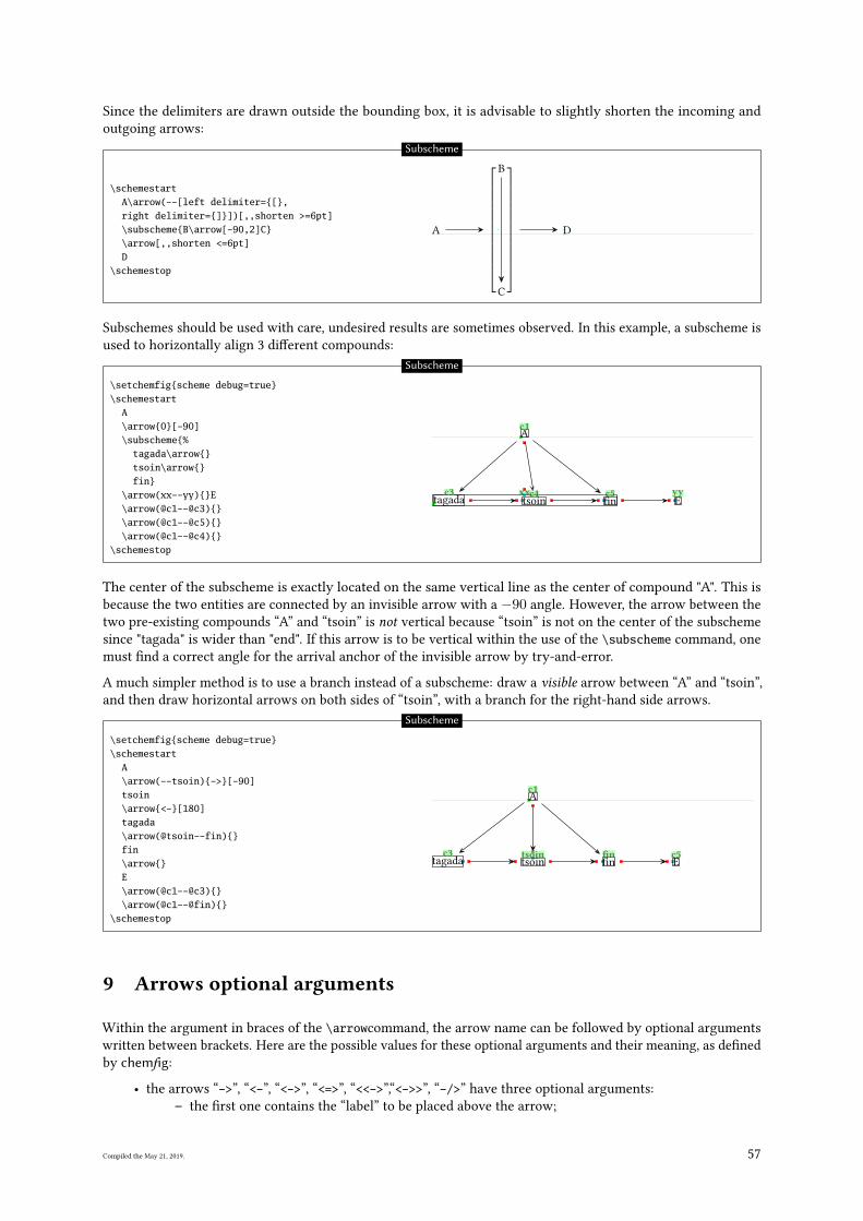
Since the delimiters are drawn outside the bounding box, it is advisable to slightly shorten the incoming and
outgoing arrows:
\schemestartA\arrow(--[left delimiter={[},right delimiter={]}])[,,shorten >=6pt]\subscheme{B\arrow[-90,2]C}\arrow[,,shorten <=6pt]D
\schemestop
A
B
C
D
Subscheme
Subschemes should be used with care, undesired results are sometimes observed. In this example, a subscheme is
used to horizontally align 3 di�erent compounds:
\setchemfig{scheme debug=true}\schemestart
A\arrow{0}[-90]\subscheme{%
tagada\arrow{}tsoin\arrow{}fin}
\arrow(xx--yy){}E\arrow(@c1--@c3){}\arrow(@c1--@c5){}\arrow(@c1--@c4){}
\schemestop
A
c1
tagada
c3tsoin
c4�n
c5xxE
yy
Subscheme
The center of the subscheme is exactly located on the same vertical line as the center of compound "A". This is
because the two entities are connected by an invisible arrow with a −90 angle. However, the arrow between the
two pre-existing compounds “A” and “tsoin” is not vertical because “tsoin” is not on the center of the subscheme
since "tagada" is wider than "end". If this arrow is to be vertical within the use of the \subscheme command, one
must �nd a correct angle for the arrival anchor of the invisible arrow by try-and-error.
A much simpler method is to use a branch instead of a subscheme: draw a visible arrow between “A” and “tsoin”,
and then draw horizontal arrows on both sides of “tsoin”, with a branch for the right-hand side arrows.
\setchemfig{scheme debug=true}\schemestart
A\arrow(--tsoin){->}[-90]tsoin\arrow{<-}[180]tagada\arrow(@tsoin--fin){}fin\arrow{}E\arrow(@c1--@c3){}\arrow(@c1--@fin){}
\schemestop
A
c1
tsoin
tsointagada
c3�n
�nE
c5
Subscheme
9 Arrows optional arguments
Within the argument in braces of the \arrowcommand, the arrow name can be followed by optional arguments
written between brackets. Here are the possible values for these optional arguments and their meaning, as de�ned
by chemfig:
• the arrows “->”, “<-”, “<->”, “<=>”, “<<->”,“<->>”, “-/>” have three optional arguments:
– the �rst one contains the “label” to be placed above the arrow;
Compiled the May 21, 2019. 57
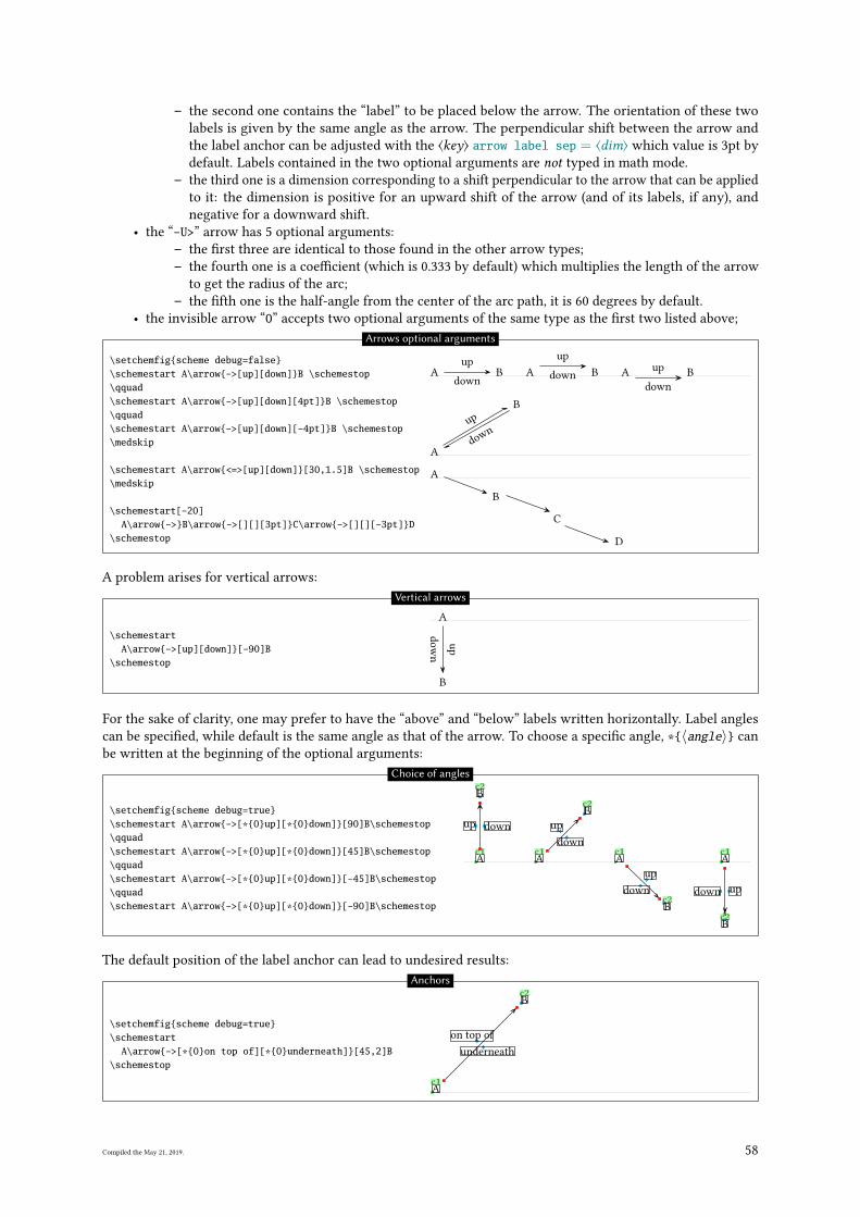
– the second one contains the “label” to be placed below the arrow. The orientation of these two
labels is given by the same angle as the arrow. The perpendicular shift between the arrow and
the label anchor can be adjusted with the ⟨key⟩ arrow label sep = ⟨dim⟩ which value is 3pt by
default. Labels contained in the two optional arguments are not typed in math mode.
– the third one is a dimension corresponding to a shift perpendicular to the arrow that can be applied
to it: the dimension is positive for an upward shift of the arrow (and of its labels, if any), and
negative for a downward shift.
• the “-U>” arrow has 5 optional arguments:
– the �rst three are identical to those found in the other arrow types;
– the fourth one is a coe�cient (which is 0.333 by default) which multiplies the length of the arrow
to get the radius of the arc;
– the �fth one is the half-angle from the center of the arc path, it is 60 degrees by default.
• the invisible arrow “0” accepts two optional arguments of the same type as the �rst two listed above;
\setchemfig{scheme debug=false}\schemestart A\arrow{->[up][down]}B \schemestop\qquad\schemestart A\arrow{->[up][down][4pt]}B \schemestop\qquad\schemestart A\arrow{->[up][down][-4pt]}B \schemestop\medskip
\schemestart A\arrow{<=>[up][down]}[30,1.5]B \schemestop\medskip
\schemestart[-20]A\arrow{->}B\arrow{->[][][3pt]}C\arrow{->[][][-3pt]}D
\schemestop
A
up
down
B A
up
downB A
up
down
B
A
up
dow
n
B
A
B
C
D
Arrows optional arguments
A problem arises for vertical arrows:
\schemestartA\arrow{->[up][down]}[-90]B
\schemestop
A
up
dow
n
B
Vertical arrows
For the sake of clarity, one may prefer to have the “above” and “below” labels written horizontally. Label angles
can be speci�ed, while default is the same angle as that of the arrow. To choose a speci�c angle, *{〈angle〉} can
be written at the beginning of the optional arguments:
\setchemfig{scheme debug=true}\schemestart A\arrow{->[*{0}up][*{0}down]}[90]B\schemestop\qquad\schemestart A\arrow{->[*{0}up][*{0}down]}[45]B\schemestop\qquad\schemestart A\arrow{->[*{0}up][*{0}down]}[-45]B\schemestop\qquad\schemestart A\arrow{->[*{0}up][*{0}down]}[-90]B\schemestop
A
c1
updown
B
c2
A
c1
up
down
B
c2
A
c1
up
down
B
c2
A
c1
updown
B
c2
Choice of angles
The default position of the label anchor can lead to undesired results:
\setchemfig{scheme debug=true}\schemestart
A\arrow{->[*{0}on top of][*{0}underneath]}[45,2]B\schemestop
A
c1
on top of
underneath
B
c2Anchors
Compiled the May 21, 2019. 58
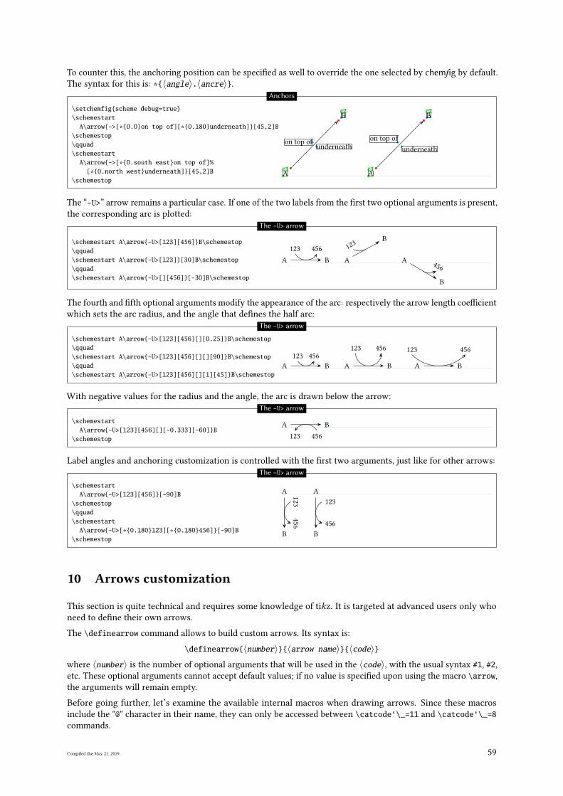
To counter this, the anchoring position can be speci�ed as well to override the one selected by chemfig by default.
The syntax for this is: *{〈angle〉.〈ancre〉}.
\setchemfig{scheme debug=true}\schemestart
A\arrow{->[*{0.0}on top of][*{0.180}underneath]}[45,2]B\schemestop\qquad\schemestart
A\arrow{->[*{0.south east}on top of]%[*{0.north west}underneath]}[45,2]B
\schemestopA
c1
on top of
underneath
B
c2
A
c1
on top of
underneath
B
c2
Anchors
The “-U>” arrow remains a particular case. If one of the two labels from the �rst two optional arguments is present,
the corresponding arc is plotted:
\schemestart A\arrow{-U>[123][456]}B\schemestop\qquad\schemestart A\arrow{-U>[123]}[30]B\schemestop\qquad\schemestart A\arrow{-U>[][456]}[-30]B\schemestop
A
123 456
B A
123
B
A456
B
The -U> arrow
The fourth and �fth optional arguments modify the appearance of the arc: respectively the arrow length coe�cient
which sets the arc radius, and the angle that de�nes the half arc:
\schemestart A\arrow{-U>[123][456][][0.25]}B\schemestop\qquad\schemestart A\arrow{-U>[123][456][][][90]}B\schemestop\qquad\schemestart A\arrow{-U>[123][456][][1][45]}B\schemestop
A
123 456
B A
123 456
B A
123 456
B
The -U> arrow
With negative values for the radius and the angle, the arc is drawn below the arrow:
\schemestartA\arrow{-U>[123][456][][-0.333][-60]}B
\schemestop
A
456123
B
The -U> arrow
Label angles and anchoring customization is controlled with the �rst two arguments, just like for other arrows:
\schemestartA\arrow{-U>[123][456]}[-90]B
\schemestop\qquad\schemestart
A\arrow{-U>[*{0.180}123][*{0.180}456]}[-90]B\schemestop
A
123
456
B
A
123
456
B
The -U> arrow
10 Arrows customization
This section is quite technical and requires some knowledge of tikz. It is targeted at advanced users only who
need to de�ne their own arrows.
The \definearrow command allows to build custom arrows. Its syntax is:
\definearrow{〈number〉}{〈arrow name〉}{〈code〉}where 〈number〉 is the number of optional arguments that will be used in the 〈code〉, with the usual syntax #1, #2,
etc. These optional arguments cannot accept default values; if no value is speci�ed upon using the macro \arrow,
the arguments will remain empty.
Before going further, let’s examine the available internal macros when drawing arrows. Since these macros
include the "@" character in their name, they can only be accessed between \catcode‘\_=11 and \catcode‘\_=8commands.
Compiled the May 21, 2019. 59
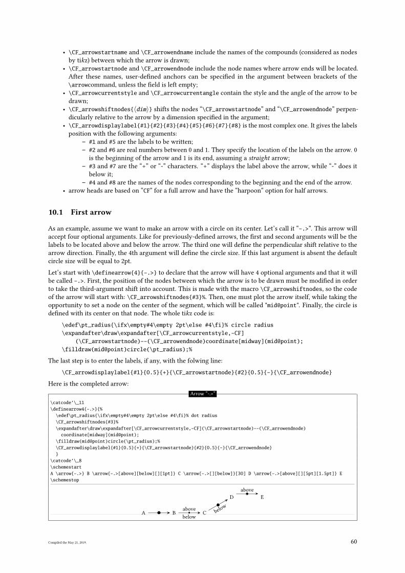
• \CF_arrowstartname and \CF_arrowendname include the names of the compounds (considered as nodes
by tikz) between which the arrow is drawn;
• \CF_arrowstartnode and \CF_arrowendnode include the node names where arrow ends will be located.
After these names, user-de�ned anchors can be speci�ed in the argument between brackets of the
\arrowcommand, unless the �eld is left empty;
• \CF_arrowcurrentstyle and \CF_arrowcurrentangle contain the style and the angle of the arrow to be
drawn;
• \CF_arrowshiftnodes{〈dim〉} shifts the nodes “\CF_arrowstartnode” and “\CF_arrowendnode” perpen-
dicularly relative to the arrow by a dimension speci�ed in the argument;
• \CF_arrowdisplaylabel{#1}{#2}{#3}{#4}{#5}{#6}{#7}{#8} is the most complex one. It gives the labels
position with the following arguments:
– #1 and #5 are the labels to be written;
– #2 and #6 are real numbers between 0 and 1. They specify the location of the labels on the arrow. 0
is the beginning of the arrow and 1 is its end, assuming a straight arrow;
– #3 and #7 are the “+” or “-” characters. “+” displays the label above the arrow, while “-” does it
below it;
– #4 and #8 are the names of the nodes corresponding to the beginning and the end of the arrow.
• arrow heads are based on “CF” for a full arrow and have the “harpoon” option for half arrows.
10.1 First arrow
As an example, assume we want to make an arrow with a circle on its center. Let’s call it “-.>”. This arrow will
accept four optional arguments. Like for previously-de�ned arrows, the �rst and second arguments will be the
labels to be located above and below the arrow. The third one will de�ne the perpendicular shift relative to the
arrow direction. Finally, the 4th argument will de�ne the circle size. If this last argument is absent the default
circle size will be equal to 2pt.
Let’s start with \definearrow{4}{-.>} to declare that the arrow will have 4 optional arguments and that it will
be called -.>. First, the position of the nodes between which the arrow is to be drawn must be modi�ed in order
to take the third-argument shift into account. This is made with the macro \CF_arrowshiftnodes, so the code
of the arrow will start with: \CF_arrowshiftnodes{#3}%. Then, one must plot the arrow itself, while taking the
opportunity to set a node on the center of the segment, which will be called "mid@point". Finally, the circle is
de�ned with its center on that node. The whole tikz code is:
\edef\pt_radius{\ifx\empty#4\empty 2pt\else #4\fi}% circle radius\expandafter\draw\expandafter[\CF_arrowcurrentstyle,-CF]
(\CF_arrowstartnode)--(\CF_arrowendnode)coordinate[midway](mid@point);\filldraw(mid@point)circle(\pt_radius);%
The last step is to enter the labels, if any, with the folwing line:
\CF_arrowdisplaylabel{#1}{0.5}{+}{\CF_arrowstartnode}{#2}{0.5}{-}{\CF_arrowendnode}
Here is the completed arrow:
Arrow “-.>”
\catcode‘\_11\definearrow4{-.>}{%
\edef\pt_radius{\ifx\empty#4\empty 2pt\else #4\fi}% dot radius\CF_arrowshiftnodes{#3}%\expandafter\draw\expandafter[\CF_arrowcurrentstyle,-CF](\CF_arrowstartnode)--(\CF_arrowendnode)
coordinate[midway](mid@point);\filldraw(mid@point)circle(\pt_radius);%\CF_arrowdisplaylabel{#1}{0.5}{+}{\CF_arrowstartnode}{#2}{0.5}{-}{\CF_arrowendnode}}
\catcode‘\_8\schemestartA \arrow{-.>} B \arrow{-.>[above][below][][1pt]} C \arrow{-.>[][below]}[30] D \arrow{-.>[above][][5pt][1.5pt]} E\schemestop
A B
above
below
C belo
w
D
above
E
Compiled the May 21, 2019. 60
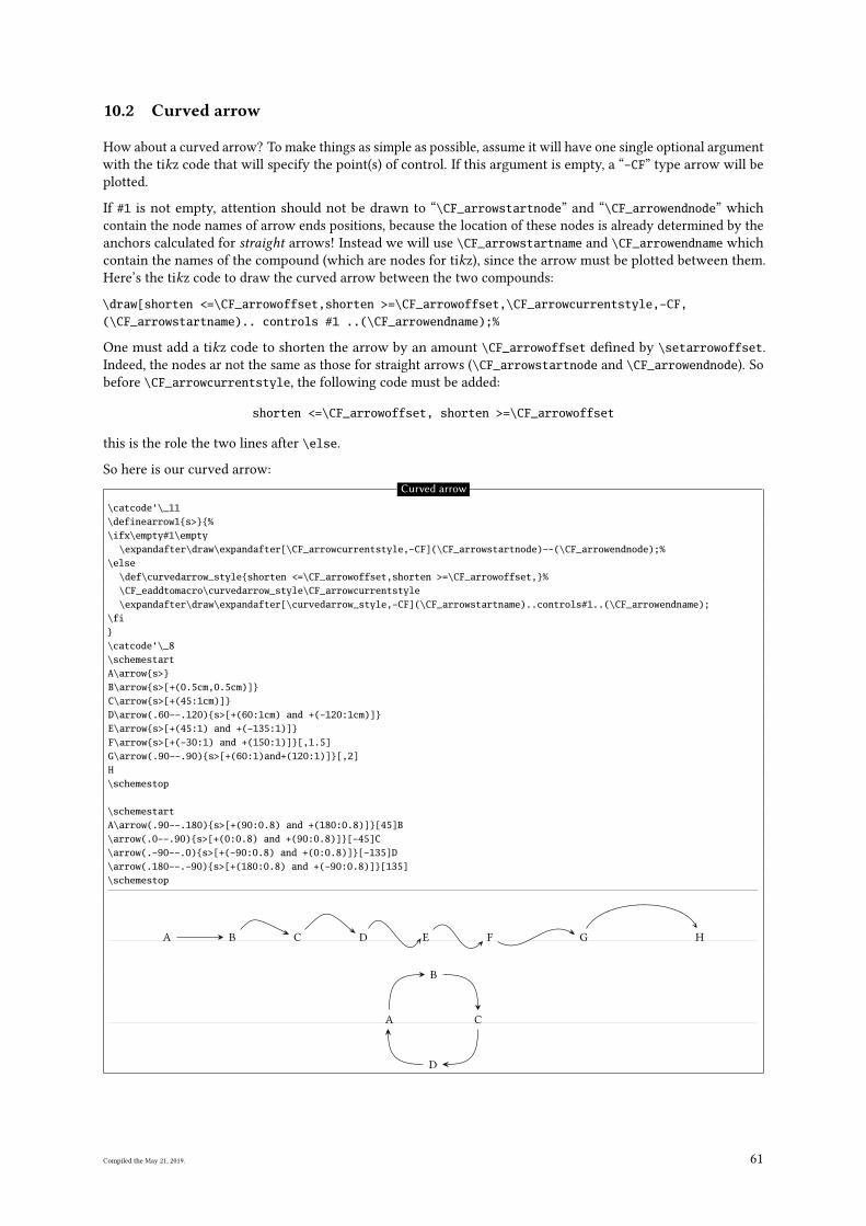
10.2 Curved arrow
How about a curved arrow? To make things as simple as possible, assume it will have one single optional argument
with the tikz code that will specify the point(s) of control. If this argument is empty, a “-CF” type arrow will be
plotted.
If #1 is not empty, attention should not be drawn to “\CF_arrowstartnode” and “\CF_arrowendnode” which
contain the node names of arrow ends positions, because the location of these nodes is already determined by the
anchors calculated for straight arrows! Instead we will use \CF_arrowstartname and \CF_arrowendname which
contain the names of the compound (which are nodes for tikz), since the arrow must be plotted between them.
Here’s the tikz code to draw the curved arrow between the two compounds:
\draw[shorten <=\CF_arrowoffset,shorten >=\CF_arrowoffset,\CF_arrowcurrentstyle,-CF,(\CF_arrowstartname).. controls #1 ..(\CF_arrowendname);%
One must add a tikz code to shorten the arrow by an amount \CF_arrowoffset de�ned by \setarrowoffset.
Indeed, the nodes ar not the same as those for straight arrows (\CF_arrowstartnode and \CF_arrowendnode). So
before \CF_arrowcurrentstyle, the following code must be added:
shorten <=\CF_arrowoffset, shorten >=\CF_arrowoffset
this is the role the two lines after \else.
So here is our curved arrow:
Curved arrow
\catcode‘\_11\definearrow1{s>}{%\ifx\empty#1\empty
\expandafter\draw\expandafter[\CF_arrowcurrentstyle,-CF](\CF_arrowstartnode)--(\CF_arrowendnode);%\else
\def\curvedarrow_style{shorten <=\CF_arrowoffset,shorten >=\CF_arrowoffset,}%\CF_eaddtomacro\curvedarrow_style\CF_arrowcurrentstyle\expandafter\draw\expandafter[\curvedarrow_style,-CF](\CF_arrowstartname)..controls#1..(\CF_arrowendname);
\fi}\catcode‘\_8\schemestartA\arrow{s>}B\arrow{s>[+(0.5cm,0.5cm)]}C\arrow{s>[+(45:1cm)]}D\arrow(.60--.120){s>[+(60:1cm) and +(-120:1cm)]}E\arrow{s>[+(45:1) and +(-135:1)]}F\arrow{s>[+(-30:1) and +(150:1)]}[,1.5]G\arrow(.90--.90){s>[+(60:1)and+(120:1)]}[,2]H\schemestop
\schemestartA\arrow(.90--.180){s>[+(90:0.8) and +(180:0.8)]}[45]B\arrow(.0--.90){s>[+(0:0.8) and +(90:0.8)]}[-45]C\arrow(.-90--.0){s>[+(-90:0.8) and +(0:0.8)]}[-135]D\arrow(.180--.-90){s>[+(180:0.8) and +(-90:0.8)]}[135]\schemestop
A B C D E F G H
A
B
C
D
Compiled the May 21, 2019. 61
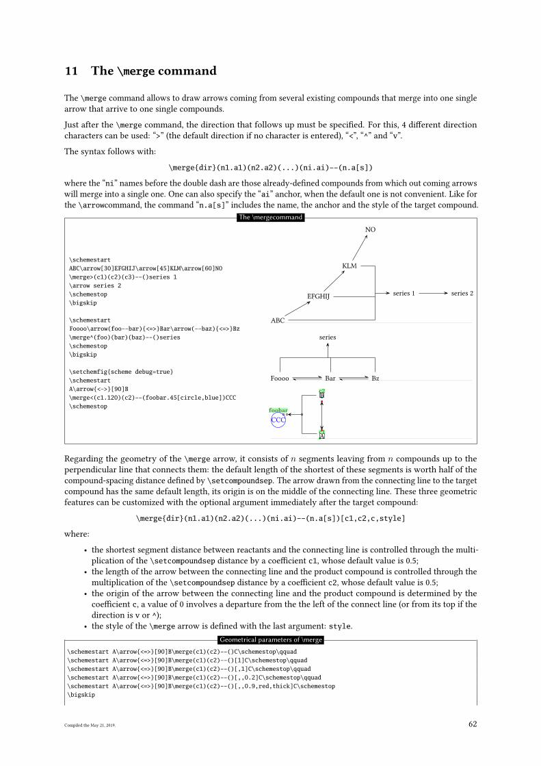
11 The \merge command
The \merge command allows to draw arrows coming from several existing compounds that merge into one single
arrow that arrive to one single compounds.
Just after the \merge command, the direction that follows up must be speci�ed. For this, 4 di�erent direction
characters can be used: “>” (the default direction if no character is entered), “<”, “^” and “v”.
The syntax follows with:
\merge{dir}(n1.a1)(n2.a2)(...)(ni.ai)--(n.a[s])
where the “ni” names before the double dash are those already-de�ned compounds from which out coming arrows
will merge into a single one. One can also specify the “ai” anchor, when the default one is not convenient. Like for
the \arrowcommand, the command “n.a[s]” includes the name, the anchor and the style of the target compound.
\schemestartABC\arrow[30]EFGHIJ\arrow[45]KLM\arrow[60]NO\merge>(c1)(c2)(c3)--()series 1\arrow series 2\schemestop\bigskip
\schemestartFoooo\arrow(foo--bar){<=>}Bar\arrow(--baz){<=>}Bz\merge^(foo)(bar)(baz)--()series\schemestop\bigskip
\setchemfig{scheme debug=true}\schemestartA\arrow{<->}[90]B\merge<(c1.120)(c2)--(foobar.45[circle,blue])CCC\schemestop
ABC
EFGHIJ
KLM
NO
series 1 series 2
Foooo Bar Bz
series
A
c1
B
c2
CCC
foobar
The \mergecommand
Regarding the geometry of the \merge arrow, it consists of n segments leaving from n compounds up to the
perpendicular line that connects them: the default length of the shortest of these segments is worth half of the
compound-spacing distance de�ned by \setcompoundsep. The arrow drawn from the connecting line to the target
compound has the same default length, its origin is on the middle of the connecting line. These three geometric
features can be customized with the optional argument immediately after the target compound:
\merge{dir}(n1.a1)(n2.a2)(...)(ni.ai)--(n.a[s])[c1,c2,c,style]
where:
• the shortest segment distance between reactants and the connecting line is controlled through the multi-
plication of the \setcompoundsep distance by a coe�cient c1, whose default value is 0.5;
• the length of the arrow between the connecting line and the product compound is controlled through the
multiplication of the \setcompoundsep distance by a coe�cient c2, whose default value is 0.5;
• the origin of the arrow between the connecting line and the product compound is determined by the
coe�cient c, a value of 0 involves a departure from the the left of the connect line (or from its top if the
direction is v or ^);
• the style of the \merge arrow is de�ned with the last argument: style.
Geometrical parameters of \merge
\schemestart A\arrow{<=>}[90]B\merge(c1)(c2)--()C\schemestop\qquad\schemestart A\arrow{<=>}[90]B\merge(c1)(c2)--()[1]C\schemestop\qquad\schemestart A\arrow{<=>}[90]B\merge(c1)(c2)--()[,1]C\schemestop\qquad\schemestart A\arrow{<=>}[90]B\merge(c1)(c2)--()[,,0.2]C\schemestop\qquad\schemestart A\arrow{<=>}[90]B\merge(c1)(c2)--()[,,0.9,red,thick]C\schemestop\bigskip
Compiled the May 21, 2019. 62
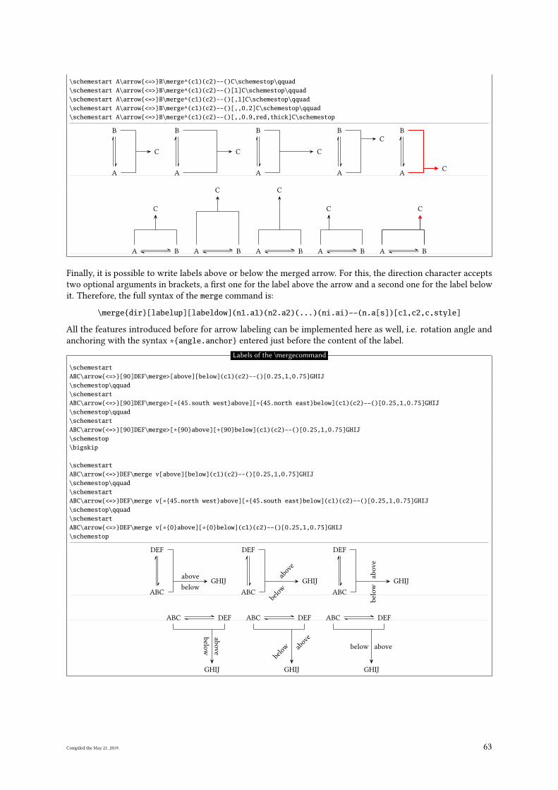
\schemestart A\arrow{<=>}B\merge^(c1)(c2)--()C\schemestop\qquad\schemestart A\arrow{<=>}B\merge^(c1)(c2)--()[1]C\schemestop\qquad\schemestart A\arrow{<=>}B\merge^(c1)(c2)--()[,1]C\schemestop\qquad\schemestart A\arrow{<=>}B\merge^(c1)(c2)--()[,,0.2]C\schemestop\qquad\schemestart A\arrow{<=>}B\merge^(c1)(c2)--()[,,0.9,red,thick]C\schemestop
A
B
C
A
B
C
A
B
C
A
B
C
A
B
C
A B
C
A B
C
A B
C
A B
C
A B
C
Finally, it is possible to write labels above or below the merged arrow. For this, the direction character accepts
two optional arguments in brackets, a �rst one for the label above the arrow and a second one for the label below
it. Therefore, the full syntax of the merge command is:
\merge{dir}[labelup][labeldow](n1.a1)(n2.a2)(...)(ni.ai)--(n.a[s])[c1,c2,c,style]
All the features introduced before for arrow labeling can be implemented here as well, i.e. rotation angle and
anchoring with the syntax *{angle.anchor} entered just before the content of the label.
Labels of the \mergecommand
\schemestartABC\arrow{<=>}[90]DEF\merge>[above][below](c1)(c2)--()[0.25,1,0.75]GHIJ\schemestop\qquad\schemestartABC\arrow{<=>}[90]DEF\merge>[*{45.south west}above][*{45.north east}below](c1)(c2)--()[0.25,1,0.75]GHIJ\schemestop\qquad\schemestartABC\arrow{<=>}[90]DEF\merge>[*{90}above][*{90}below](c1)(c2)--()[0.25,1,0.75]GHIJ\schemestop\bigskip
\schemestartABC\arrow{<=>}DEF\merge v[above][below](c1)(c2)--()[0.25,1,0.75]GHIJ\schemestop\qquad\schemestartABC\arrow{<=>}DEF\merge v[*{45.north west}above][*{45.south east}below](c1)(c2)--()[0.25,1,0.75]GHIJ\schemestop\qquad\schemestartABC\arrow{<=>}DEF\merge v[*{0}above][*{0}below](c1)(c2)--()[0.25,1,0.75]GHIJ\schemestop
ABC
DEF
above
below
GHIJ
ABC
DEF
above
belo
w
GHIJ
ABC
DEF
ab
ove
below
GHIJ
ABC DEF
ab
ove
below
GHIJ
ABC DEF
above
belo
w
GHIJ
ABC DEF
abovebelow
GHIJ
Compiled the May 21, 2019. 63
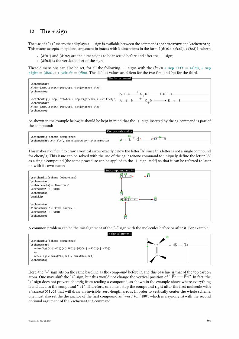
12 The + sign
The use of a “\+” macro that displays a + sign is available between the commands \schemestart and \schemestop.
This macro accepts an optional argument in braces with 3 dimensions in the form {〈dim1〉,〈dim2〉,〈dim3〉}, where:
• 〈dim1〉 and 〈dim2〉 are the dimensions to be inserted before and after the + sign;
• 〈dim3〉 is the vertical o�set of the sign.
These dimensions can also be set, for all the following + signs with the ⟨keys⟩ + sep left = ⟨dim⟩, + sepright = ⟨dim⟩ et + vshift = ⟨dim⟩. The default values are 0.5em for the two �rst and 0pt for the third.
\schemestartA\+B\+{2em,,5pt}C\+{0pt,0pt,-5pt}D\arrow E\+F\schemestop
\setchemfig{+ sep left=1em,+ sep right=1em,+ vshift=0pt}\schemestartA\+B\+{2em,,5pt}C\+{0pt,0pt,-5pt}D\arrow E\+F\schemestop
A + B
+C
+D E + F
A + B
+C
+D E + F
The \+ command
As shown in the example below, it should be kept in mind that the + sign inserted by the \+ command is part of
the compound:
\setchemfig{scheme debug=true}\schemestart A\+ B\+{,,5pt}C\arrow D\+ E\schemestop A + B
+C
c1D + E
c2
Compounds and \+
This makes it di�cult to draw a vertical arrow exactly below the letter “A” since this letter is not a single compound
for chemfig. This issue can be solved with the use of the \subscheme command to uniquely de�ne the letter “A”
as a single compound (the same procedure can be applied to the + sign itself) so that it can be referred to later
on with its own name:
\setchemfig{scheme debug=true}\schemestart\subscheme{A}\+ B\arrow C\arrow(@c2--)[-90]E\schemestop\medskip
\schemestartA\subscheme{\+}BCDEF \arrow G\arrow(@c2--)[-90]H\schemestop
A
c2+ B
c1C
c3
E
c4
A +c2
BCDEF
c1G
c3
H
c4
Subcompound and \+
A common problem can be the misalignment of the “+” sign with the molecules before or after it. For example:
\setchemfig{scheme debug=true}\schemestart
\chemfig{C(<[:40])(<[:160])=[6]C(<[:-130])<[:-20]}\+\chemfig{\lewis{246,Br}-\lewis{026,Br}}
\schemestop
C
C
+ Br Br
c1+ sign alignment
Here, the “+” sign sits on the same baseline as the compound before it, and this baseline is that of the top carbon
atom. One may shift the “+” sign, but this would not change the vertical position of “ Br Br ”. In fact, the
“+” sign does not prevent chemfig from reading a compound, as shown in the example above where everything
is included in the compound “ c1”. Therefore, one must stop the compound right after the �rst molecule with
a \arrow{0}[,0] that will draw an invisible, zero-length arrow. In order to vertically center the whole scheme,
one must also set the the anchor of the �rst compound as “west” (or “180”, which is a synonym) with the second
optional argument of the \schemestart command:
Compiled the May 21, 2019. 64
\setchemfig{scheme debug=true}\schemestart[][west]
\chemfig{C(<[:40])(<[:160])=[6]C(<[:-130])<[:-20]}\arrow{0}[,0]\+\chemfig{\lewis{246,Br}-\lewis{026,Br}}
\schemestop
C
C
c1
+ Br Brc2
+ sign alignment
Thus, the �rst compound “ c1” consists of the �rst molecule and the second compound consists of everything
else, i.e. the “+” sign and the second molecule. Alternatively, one can play with anchors or styles via the \arrowcommand to move the second compound to another location. Here, for example, the second compound is shifted
downwards by 10pt in the �rst case. In the second case, the “south east” anchor of the �rst compound matches
the “south west” anchor of the second one:
\setchemfig{scheme debug=true}\schemestart[][west]
\chemfig{C(<[:40])(<[:160])=[6]C(<[:-130])<[:-20]}\arrow(--[yshift=-10pt]){0}[,0]\+\chemfig{\lewis{246,Br}-\lewis{026,Br}}
\schemestop\medskip
\schemestart[][west]\chemfig{C(<[:40])(<[:160])=[6]C(<[:-130])<[:-20]}\arrow(.south east--.south west){0}[,0]\+\chemfig{\lewis{246,Br}-\lewis{026,Br}}
\schemestop
C
C
c1
+ Br Brc2
C
C
c1
+ Br Brc2
+ sign alignment
Compiled the May 21, 2019. 65
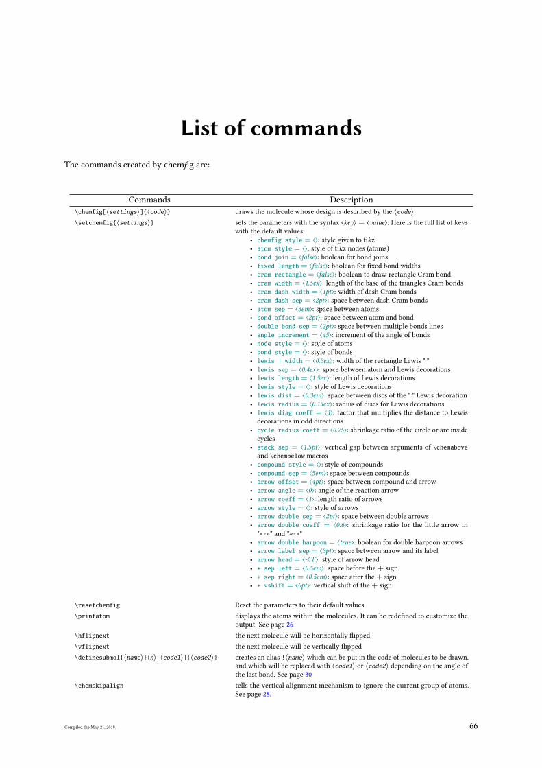
List of commandsThe commands created by chemfig are:
Commands Description
\chemfig[〈settings〉]{〈code〉} draws the molecule whose design is described by the 〈code〉\setchemfig{〈settings〉} sets the parameters with the syntax ⟨key⟩ = ⟨value⟩. Here is the full list of keys
with the default values:
• chemfig style = ⟨⟩: style given to tikz
• atom style = ⟨⟩: style of tikz nodes (atoms)
• bond join = ⟨false⟩: boolean for bond joins
• fixed length = ⟨false⟩: boolean for �xed bond widths
• cram rectangle = ⟨false⟩: boolean to draw rectangle Cram bond
• cram width = ⟨1.5ex⟩: length of the base of the triangles Cram bonds
• cram dash width = ⟨1pt⟩: width of dash Cram bonds
• cram dash sep = ⟨2pt⟩: space between dash Cram bonds
• atom sep = ⟨3em⟩: space between atoms
• bond offset = ⟨2pt⟩: space between atom and bond
• double bond sep = ⟨2pt⟩: space between multiple bonds lines
• angle increment = ⟨45⟩: increment of the angle of bonds
• node style = ⟨⟩: style of atoms
• bond style = ⟨⟩: style of bonds
• lewis | width = ⟨0.3ex⟩: width of the rectangle Lewis "|"
• lewis sep = ⟨0.4ex⟩: space between atom and Lewis decorations
• lewis length = ⟨1.5ex⟩: length of Lewis decorations
• lewis style = ⟨⟩: style of Lewis decorations
• lewis dist = ⟨0.3em⟩: space between discs of the ":" Lewis decoration
• lewis radius = ⟨0.15ex⟩: radius of discs for Lewis decorations
• lewis diag coeff = ⟨1⟩: factor that multiplies the distance to Lewis
decorations in odd directions
• cycle radius coeff = ⟨0.75⟩: shrinkage ratio of the circle or arc inside
cycles
• stack sep = ⟨1.5pt⟩: vertical gap between arguments of \chemaboveand \chembelow macros
• compound style = ⟨⟩: style of compounds
• compound sep = ⟨5em⟩: space between compounds
• arrow offset = ⟨4pt⟩: space between compound and arrow
• arrow angle = ⟨0⟩: angle of the reaction arrow
• arrow coeff = ⟨1⟩: length ratio of arrows
• arrow style = ⟨⟩: style of arrows
• arrow double sep = ⟨2pt⟩: space between double arrows
• arrow double coeff = ⟨0.6⟩: shrinkage ratio for the little arrow in
"<-»" and "«->"
• arrow double harpoon = ⟨true⟩: boolean for double harpoon arrows
• arrow label sep = ⟨3pt⟩: space between arrow and its label
• arrow head = ⟨-CF⟩: style of arrow head
• + sep left = ⟨0.5em⟩: space before the + sign
• + sep right = ⟨0.5em⟩: space after the + sign
• + vshift = ⟨0pt⟩: vertical shift of the + sign
\resetchemfig Reset the parameters to their default values
\printatom displays the atoms within the molecules. It can be rede�ned to customize the
output. See page 26
\hflipnext the next molecule will be horizontally �ipped
\vflipnext the next molecule will be vertically �ipped
\definesubmol{〈name〉}〈n〉[〈code1〉]{〈code2〉} creates an alias !〈name〉 which can be put in the code of molecules to be drawn,
and which will be replaced with 〈code1〉 or 〈code2〉 depending on the angle of
the last bond. See page 30
\chemskipalign tells the vertical alignment mechanism to ignore the current group of atoms.
See page 28.
Compiled the May 21, 2019. 66
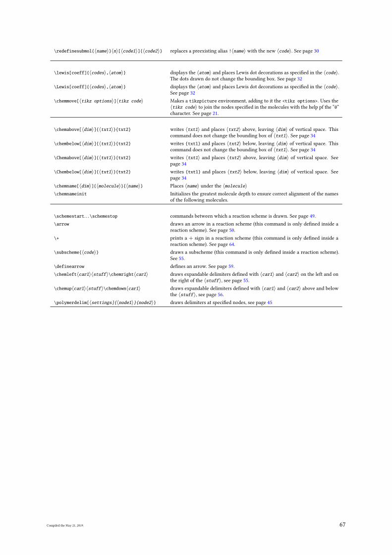
\redefinesubmol{〈name〉}〈n〉[〈code1〉]{〈code2〉} replaces a preexisting alias !〈name〉 with the new 〈code〉. See page 30
\lewis[coeff]{〈codes〉,〈atom〉} displays the 〈atom〉 and places Lewis dot decorations as speci�ed in the 〈code〉.The dots drawn do not change the bounding box. See page 32
\Lewis[coeff]{〈codes〉,〈atom〉} displays the 〈atom〉 and places Lewis dot decorations as speci�ed in the 〈code〉.See page 32
\chemmove[〈tikz options〉]〈tikz code〉 Makes a tikzpicture environment, adding to it the <tikz options>. Uses the
〈tikz code〉 to join the nodes speci�ed in the molecules with the help pf the “@”
character. See page 21.
\chemabove[〈dim〉]{〈txt1〉}{txt2} writes 〈txt1〉 and places 〈txt2〉 above, leaving 〈dim〉 of vertical space. This
command does not change the bounding box of 〈txt1〉. See page 34
\chembelow[〈dim〉]{〈txt1〉}{txt2} writes {txt1} and places 〈txt2〉 below, leaving 〈dim〉 of vertical space. This
command does not change the bounding box of 〈txt1〉. See page 34
\Chemabove[〈dim〉]{〈txt1〉}{txt2} writes 〈txt1〉 and places 〈txt2〉 above, leaving 〈dim〉 of vertical space. See
page 34
\Chembelow[〈dim〉]{〈txt1〉}{txt2} writes {txt1} and places 〈txt2〉 below, leaving 〈dim〉 of vertical space. See
page 34
\chemname[〈dim〉]{〈molecule〉}{〈name〉} Places 〈name〉 under the 〈molecule〉\chemnameinit Initializes the greatest molecule depth to ensure correct alignment of the names
of the following molecules.
\schemestart. . .\schemestop commands between which a reaction scheme is drawn. See page 49.
\arrow draws an arrow in a reaction scheme (this command is only de�ned inside a
reaction scheme). See page 50.
\+ prints a + sign in a reaction scheme (this command is only de�ned inside a
reaction scheme). See page 64.
\subscheme{〈code〉} draws a subscheme (this command is only de�ned inside a reaction scheme).
See 55.
\definearrow de�nes an arrow. See page 59.
\chemleft〈car1〉〈stuff〉\chemright〈car1〉 draws expandable delimiters de�ned with 〈car1〉 and 〈car2〉 on the left and on
the right of the 〈stuff〉, see page 55.
\chemup〈car1〉〈stuff〉\chemdown〈car1〉 draws expandable delimiters de�ned with 〈car1〉 and 〈car2〉 above and below
the 〈stuff〉, see page 56.
\polymerdelim[〈settings]{〈node1〉}{node2〉} draws delimiters at speci�ed nodes, see page 45
Compiled the May 21, 2019. 67
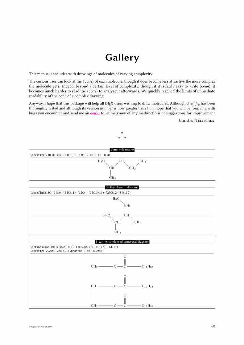
GalleryThis manual concludes with drawings of molecules of varying complexity.
The curious user can look at the 〈code〉 of each molecule, though it does become less attractive the more complex
the molecule gets. Indeed, beyond a certain level of complexity, though it it is fairly easy to write 〈code〉, it
becomes much harder to read the 〈code〉 to analyze it afterwards. We quickly reached the limits of immediate
readability of the code of a complex drawing.
Anyway, I hope that this package will help all LATEX users wishing to draw molecules. Although chemfig has been
thoroughly tested and although its version number is now greater than 1.0, I hope that you will be forgiving with
bugs you encounter and send me an email to let me know of any malfunctions or suggestions for improvement.
Christian Tellechea
?? ?
2-methylpentane
\chemfig{[7]H_3C-CH(-[6]CH_3)-[1]CH_2-CH_2-[1]CH_3}
H3C
CH
CH3
CH2
CH2
CH3
3-ethyl-2-methylhexane
\chemfig{H_3C-[7]CH(-[6]CH_3)-[1]CH(-[7]C_3H_7)-[2]CH_2-[3]H_3C}
H3C
CH
CH3
CH
C3H7
CH2
CH3
Stearine, condensed structural diagram
\definesubmol{@}{([0,2]-O-[0,1]C(=[2,1]O)-C_{17}H_{33})}\chemfig{[2,2]CH_2!@-CH_{\phantom 2}!@-CH_2!@}
CH2 O C
O
C17H33
CH O C
O
C17H33
CH2 O C
O
C17H33
Compiled the May 21, 2019. 68
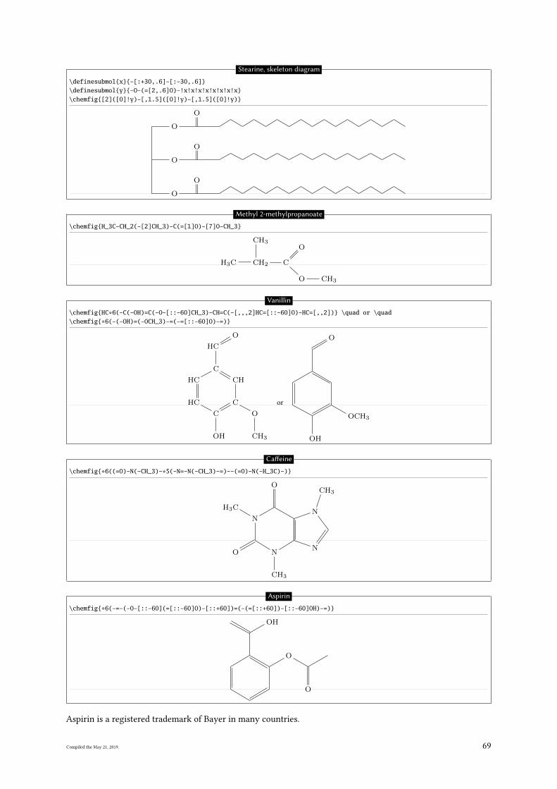
Stearine, skeleton diagram
\definesubmol{x}{-[:+30,.6]-[:-30,.6]}\definesubmol{y}{-O-(=[2,.6]O)-!x!x!x!x!x!x!x!x}\chemfig{[2]([0]!y)-[,1.5]([0]!y)-[,1.5]([0]!y)}
O
O
O
O
O
O
Methyl 2-methylpropanoate
\chemfig{H_3C-CH_2(-[2]CH_3)-C(=[1]O)-[7]O-CH_3}
H3C CH2
CH3
C
O
O CH3
Vanillin
\chemfig{HC*6(-C(-OH)=C(-O-[::-60]CH_3)-CH=C(-[,,,2]HC=[::-60]O)-HC=[,,2])} \quad or \quad\chemfig{*6(-(-OH)=(-OCH_3)-=(-=[::-60]O)-=)}
HC
C
OH
C
O
CH3
CH
C
CH
O
CH
or
OH
OCH3
O
Ca�eine
\chemfig{*6((=O)-N(-CH_3)-*5(-N=-N(-CH_3)-=)--(=O)-N(-H_3C)-)}
O N
CH3
N
N
CH3O
N
CH3
Aspirin
\chemfig{*6(-=-(-O-[::-60](=[::-60]O)-[::+60])=(-(=[::+60])-[::-60]OH)-=)}
O
O
OH
Aspirin is a registered trademark of Bayer in many countries.
Compiled the May 21, 2019. 69
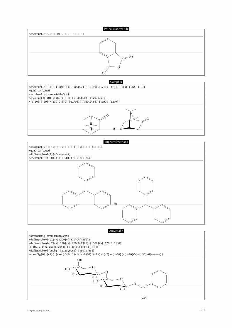
Phthalic anhydride
\chemfig{*6(=*5(-(=O)-O-(=O)-)-=-=-)}
O
O
O
Camphor
\chemfig{*6(-(<:[::120](-[::-100,0.7])(-[::100,0.7]))--(=O)-(-)(<:[::120])--)}\quad or \quad\setchemfig{cram width=3pt}\chemfig{<[:10](>[:85,1.8]?(-[:160,0.6])-[:20,0.6])>[:-10]-[:60](=[:30,0.6]O)-[:170]?(-[:30,0.6])-[:190]-[:240]}
O
or
O
Triphenylmethane
\chemfig{*6(-=-*6(-(-*6(=-=-=-))-*6(=-=-=-))=-=)}\quad or \quad\definesubmol{@}{*6(=-=-=-)}\chemfig{(-[:-30]!@)(-[:90]!@)(-[:210]!@)}
or
Amygdalin
\setchemfig{cram width=2pt}\definesubmol{c1}{-[:200]-[:120]O-[:190]}\definesubmol{c2}{-[:170](-[:200,0.7]HO)<[:300](-[:170,0.6]HO)-[:10,,,,line width=2pt](-[:-40,0.6]OH)>[:-10]}\definesubmol{csub}{-[:155,0.65]-[:90,0.65]}\chemfig{O(!{c1}(!{csub}O(!{c1}(!{csub}OH)!{c2}))!{c2})-[:-30](-[:-90]CN)-[:30]*6(=-=-=-)}
O
O
O
O
OH
OH
OHOH
OH
OHOH
CN
Compiled the May 21, 2019. 70
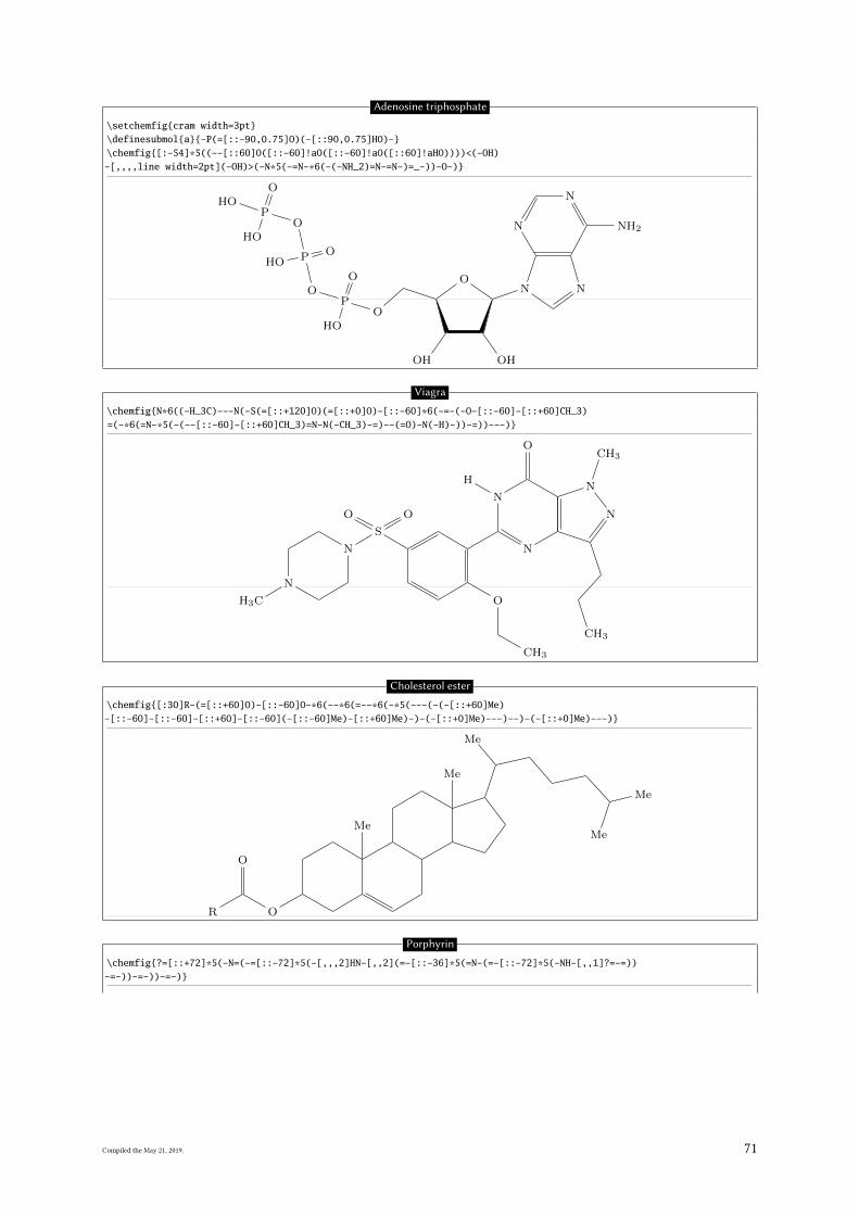
Adenosine triphosphate
\setchemfig{cram width=3pt}\definesubmol{a}{-P(=[::-90,0.75]O)(-[::90,0.75]HO)-}\chemfig{[:-54]*5((--[::60]O([::-60]!aO([::-60]!aO([::60]!aHO))))<(-OH)-[,,,,line width=2pt](-OH)>(-N*5(-=N-*6(-(-NH_2)=N-=N-)=_-))-O-)}
OP
O
OH
O
P OOH
OP
O
OH
OH
HO OH
N N
NH2
N
N
O
Viagra
\chemfig{N*6((-H_3C)---N(-S(=[::+120]O)(=[::+0]O)-[::-60]*6(-=-(-O-[::-60]-[::+60]CH_3)=(-*6(=N-*5(-(--[::-60]-[::+60]CH_3)=N-N(-CH_3)-=)--(=O)-N(-H)-))-=))---)}
N
CH3
N
S
O O
O
CH3
N
CH3
N
N
CH3O
N
H
Cholesterol ester
\chemfig{[:30]R-(=[::+60]O)-[::-60]O-*6(--*6(=--*6(-*5(---(-(-[::+60]Me)-[::-60]-[::-60]-[::+60]-[::-60](-[::-60]Me)-[::+60]Me)-)-(-[::+0]Me)---)--)-(-[::+0]Me)---)}
R
O
O
Me
Me
Me
Me
Me
Porphyrin
\chemfig{?=[::+72]*5(-N=(-=[::-72]*5(-[,,,2]HN-[,,2](=-[::-36]*5(=N-(=-[::-72]*5(-NH-[,,1]?=-=))-=-))-=-))-=-)}
Compiled the May 21, 2019. 71
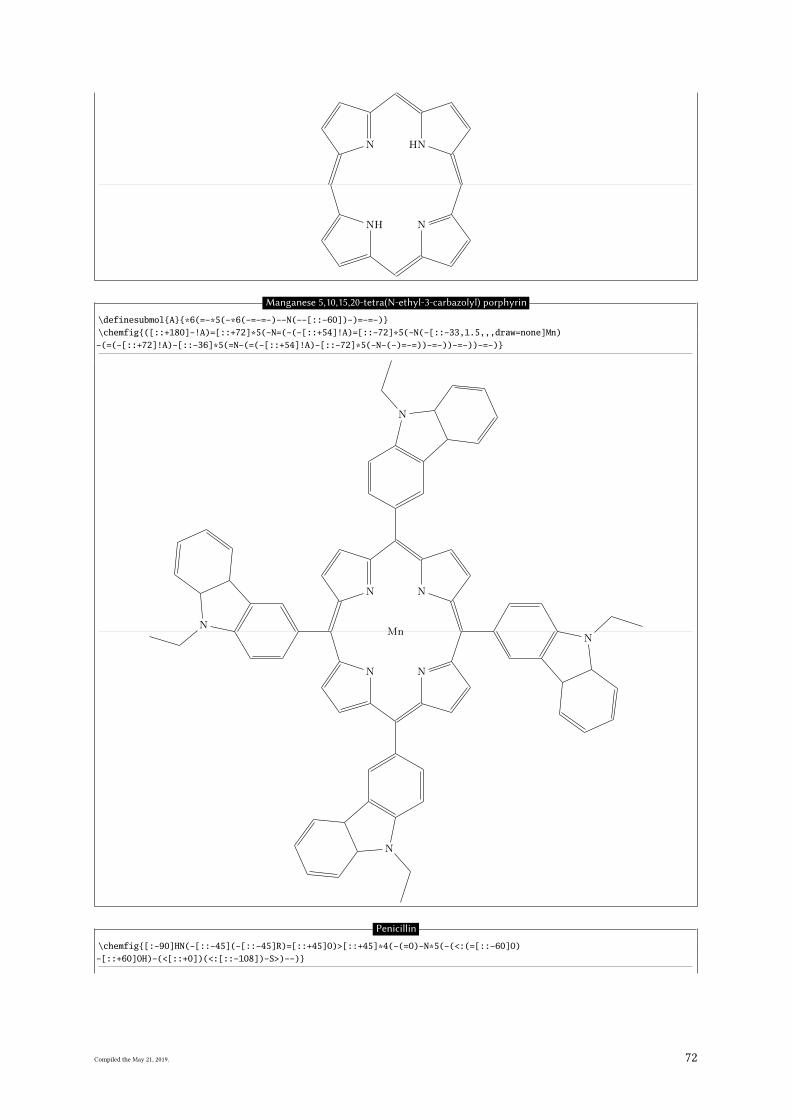
N NH
NNH
Manganese 5,10,15,20-tetra(N-ethyl-3-carbazolyl) porphyrin
\definesubmol{A}{*6(=-*5(-*6(-=-=-)--N(--[::-60])-)=-=-)}\chemfig{([::+180]-!A)=[::+72]*5(-N=(-(-[::+54]!A)=[::-72]*5(-N(-[::-33,1.5,,,draw=none]Mn)-(=(-[::+72]!A)-[::-36]*5(=N-(=(-[::+54]!A)-[::-72]*5(-N-(-)=-=))-=-))-=-))-=-)}
N
N
N
N
MnN
N
N
N
Penicillin
\chemfig{[:-90]HN(-[::-45](-[::-45]R)=[::+45]O)>[::+45]*4(-(=O)-N*5(-(<:(=[::-60]O)-[::+60]OH)-(<[::+0])(<:[::-108])-S>)--)}
Compiled the May 21, 2019. 72
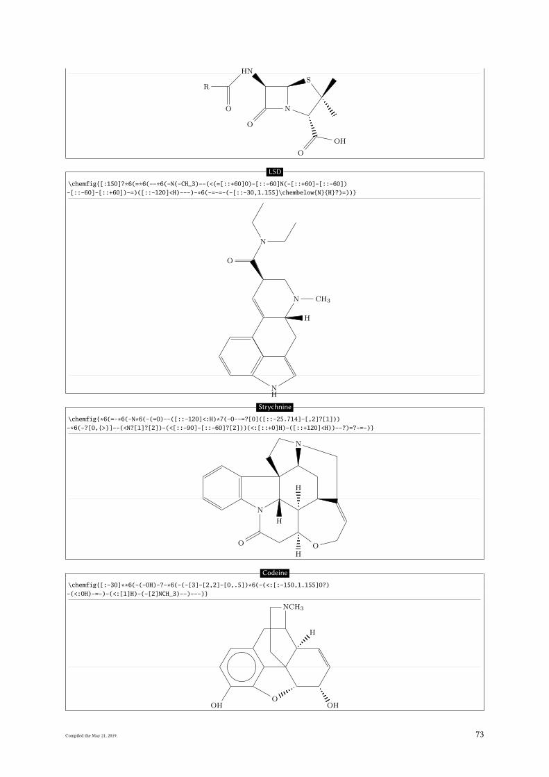
HN
R
O
O
N
O
OH
S
LSD
\chemfig{[:150]?*6(=*6(--*6(-N(-CH_3)--(<(=[::+60]O)-[::-60]N(-[::+60]-[::-60])-[::-60]-[::+60])-=)([::-120]<H)---)-*6(-=-=-(-[::-30,1.155]\chembelow{N}{H}?)=))}
N CH3
O
N
H
NH
Strychnine
\chemfig{*6(=-*6(-N*6(-(=O)--([::-120]<:H)*7(-O--=?[0]([::-25.714]-[,2]?[1]))-*6(-?[0,{>}]--(<N?[1]?[2])-(<[::-90]-[::-60]?[2]))(<:[::+0]H)-([::+120]<H))--?)=?-=-)}
N
O
HO
N
H
H
Codeine
\chemfig{[:-30]**6(-(-OH)-?-*6(-(-[3]-[2,2]-[0,.5])*6(-(<:[:-150,1.155]O?)-(<:OH)-=-)-(<:[1]H)-(-[2]NCH_3)--)---)}
HOO
OH
H
NCH3
Compiled the May 21, 2019. 73
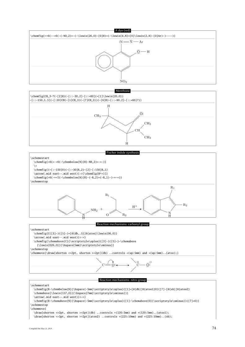
A dye (red)
\chemfig{**6(--*6(-(-NO_2)=-(-\lewis{26,O}-[0]H)=(-\lewis{4,N}=[0]\lewis{2,N}-[0]Ar)-)----)}
NO2
O H
N N Ar
Menthone
\chemfig{CH_3-?(-[2]H)(-[::-30,2]-[::+60](=[1]\lewis{20,O})-[::-150,1.5](-[:20]CH(-[1]CH_3)(-[7]CH_3))(-[6]H)-[::-90,2]-[::+60]?)}
CH3
H
O
CH
CH3
CH3
H
Fischer indole synthesis
\schemestart\chemfig{*6(=-*6(-\chembelow{N}{H}-NH_2)=-=-)}\+\chemfig{(=[:-150]O)(-[:-30]R_2)-[2]-[:150]R_1}\arrow(.mid east--.mid west){->[\chemfig{H^+}]}\chemfig{*6(-=*5(-\chembelow{N}{H}-(-R_2)=(-R_1)-)-=-=)}
\schemestop
NH
NH2+
O R2
R1
H+
NH
R2
R1
Reaction mechanisms: carbonyl group
\schemestart\chemfig{C([3]-)([5]-)=[@{db,.5}]@{atoo}\lewis{06,O}}\arrow(.mid east--.mid west){<->}\chemfig{\chemabove{C}{\scriptstyle\oplus}([3]-)([5]-)-\chemabove
{\lewis{026,O}}{\hspace{5mm}\scriptstyle\ominus}}\schemestop\chemmove{\draw[shorten <=2pt, shorten >=2pt](db) ..controls +(up:5mm) and +(up:5mm)..(atoo);}
C O⊕C
O
Reaction mechanisms: nitro group
\schemestart\chemfig{R-\chembelow{N}{\hspace{-5mm}\scriptstyle\oplus}([1]=[@{db}]@{atoo1}O)([7]-[@{sb}]@{atoo2}\chemabove{\lewis{157,O}}{\hspace{7mm}\scriptstyle\ominus})}\arrow(.mid east--.mid west){<->}\chemfig{R-\chemabove{N}{\hspace{-5mm}\scriptstyle\oplus}([1]-\chemabove{O}{\scriptstyle\ominus})([7]=O)}
\schemestop\chemmove{
\draw[shorten <=2pt, shorten >=2pt](db) ..controls +(120:5mm) and +(120:5mm)..(atoo1);\draw[shorten <=3pt, shorten >=2pt](atoo2) ..controls +(225:10mm) and +(225:10mm)..(sb);
Compiled the May 21, 2019. 74
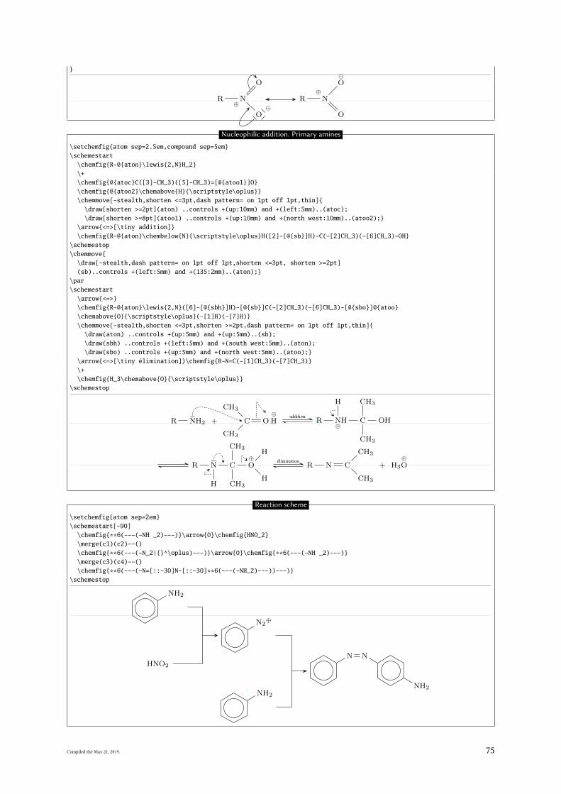
}
R N⊕
O
O
R⊕N
O
O
Nucleophilic addition. Primary amines
\setchemfig{atom sep=2.5em,compound sep=5em}\schemestart
\chemfig{R-@{aton}\lewis{2,N}H_2}\+\chemfig{@{atoc}C([3]-CH_3)([5]-CH_3)=[@{atoo1}]O}\chemfig{@{atoo2}\chemabove{H}{\scriptstyle\oplus}}\chemmove[-stealth,shorten <=3pt,dash pattern= on 1pt off 1pt,thin]{
\draw[shorten >=2pt](aton) ..controls +(up:10mm) and +(left:5mm)..(atoc);\draw[shorten >=8pt](atoo1) ..controls +(up:10mm) and +(north west:10mm)..(atoo2);}
\arrow{<=>[\tiny addition]}\chemfig{R-@{aton}\chembelow{N}{\scriptstyle\oplus}H([2]-[@{sb}]H)-C(-[2]CH_3)(-[6]CH_3)-OH}
\schemestop\chemmove{
\draw[-stealth,dash pattern= on 1pt off 1pt,shorten <=3pt, shorten >=2pt](sb)..controls +(left:5mm) and +(135:2mm)..(aton);}
\par\schemestart
\arrow{<=>}\chemfig{R-@{aton}\lewis{2,N}([6]-[@{sbh}]H)-[@{sb}]C(-[2]CH_3)(-[6]CH_3)-[@{sbo}]@{atoo}\chemabove{O}{\scriptstyle\oplus}(-[1]H)(-[7]H)}\chemmove[-stealth,shorten <=3pt,shorten >=2pt,dash pattern= on 1pt off 1pt,thin]{
\draw(aton) ..controls +(up:5mm) and +(up:5mm)..(sb);\draw(sbh) ..controls +(left:5mm) and +(south west:5mm)..(aton);\draw(sbo) ..controls +(up:5mm) and +(north west:5mm)..(atoo);}
\arrow{<=>[\tiny élimination]}\chemfig{R-N=C(-[1]CH_3)(-[7]CH_3)}\+\chemfig{H_3\chemabove{O}{\scriptstyle\oplus}}
\schemestop
R NH2 + C
H3C
H3C
O⊕H
addition
R N⊕H
H
C
CH3
CH3
OH
R N
H
C
CH3
CH3
⊕O
H
H
élimination
R N C
CH3
CH3
+ H3
⊕O
Reaction scheme
\setchemfig{atom sep=2em}\schemestart[-90]
\chemfig{**6(---(-NH _2)---)}\arrow{0}\chemfig{HNO_2}\merge(c1)(c2)--()\chemfig{**6(---(-N_2|{}^\oplus)---)}\arrow{0}\chemfig{**6(---(-NH _2)---)}\merge(c3)(c4)--()\chemfig{**6(---(-N=[::-30]N-[::-30]**6(---(-NH_2)---))---)}
\schemestop
NH2
HNO2
N2⊕
NH2
N N
NH2
Compiled the May 21, 2019. 75
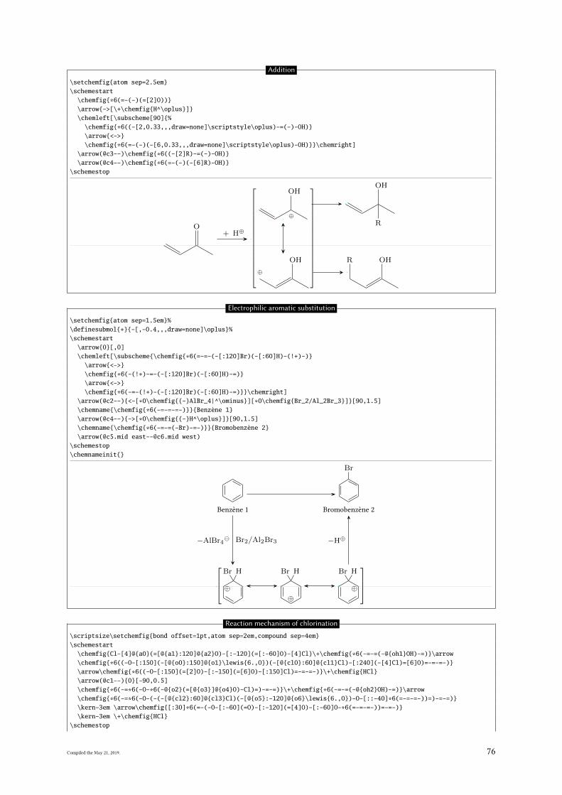
Addition
\setchemfig{atom sep=2.5em}\schemestart
\chemfig{*6(=-(-)(=[2]O))}\arrow{->[\+\chemfig{H^\oplus}]}\chemleft[\subscheme[90]{%
\chemfig{*6((-[2,0.33,,,draw=none]\scriptstyle\oplus)-=(-)-OH)}\arrow{<->}\chemfig{*6(=-(-)(-[6,0.33,,,draw=none]\scriptstyle\oplus)-OH)}}\chemright]
\arrow(@c3--)\chemfig{*6((-[2]R)-=(-)-OH)}\arrow(@c4--)\chemfig{*6(=-(-)(-[6]R)-OH)}
\schemestop
O+ H⊕
⊕ OH
⊕
OH R OH
R
OH
Electrophilic aromatic substitution
\setchemfig{atom sep=1.5em}%\definesubmol{+}{-[,-0.4,,,draw=none]\oplus}%\schemestart
\arrow{0}[,0]\chemleft[\subscheme{\chemfig{*6(=-=-(-[:120]Br)(-[:60]H)-(!+)-)}
\arrow{<->}\chemfig{*6(-(!+)-=-(-[:120]Br)(-[:60]H)-=)}\arrow{<->}\chemfig{*6(-=-(!+)-(-[:120]Br)(-[:60]H)-=)}}\chemright]
\arrow(@c2--){<-[*0\chemfig{{-}AlBr_4|^\ominus}][*0\chemfig{Br_2/Al_2Br_3}]}[90,1.5]\chemname{\chemfig{*6(-=-=-=-)}}{Benzène 1}\arrow(@c4--){->[*0\chemfig{{-}H^\oplus}]}[90,1.5]\chemname{\chemfig{*6(-=-=(-Br)-=-)}}{Bromobenzène 2}\arrow(@c5.mid [email protected] west)
\schemestop\chemnameinit{}
Br H
⊕⊕
Br H
⊕
Br H
−AlBr4 Br2/Al2Br3
Benzène 1
−H⊕
Br
Bromobenzène 2
Reaction mechanism of chlorination
\scriptsize\setchemfig{bond offset=1pt,atom sep=2em,compound sep=4em}\schemestart
\chemfig{Cl-[4]@{a0}(=[@{a1}:120]@{a2}O)-[:-120](=[:-60]O)-[4]Cl}\+\chemfig{*6(-=-=(-@{oh1}OH)-=)}\arrow\chemfig{*6((-O-[:150](-[@{o0}:150]@{o1}\lewis{6.,O})(-[@{cl0}:60]@{cl1}Cl)-[:240](-[4]Cl)=[6]O)=-=-=-)}\arrow\chemfig{*6((-O-[:150](=[2]O)-[:-150](=[6]O)-[:150]Cl)=-=-=-)}\+\chemfig{HCl}\arrow(@c1--){0}[-90,0.5]\chemfig{*6(-=*6(-O-*6(-@{o2}(=[@{o3}]@{o4}O)-Cl)=)-=-=)}\+\chemfig{*6(-=-=(-@{oh2}OH)-=)}\arrow\chemfig{*6(-=*6(-O-(-(-[@{cl2}:60]@{cl3}Cl)(-[@{o5}:-120]@{o6}\lewis{6.,O})-O-[::-40]*6(=-=-=-))=)-=-=)}\kern-3em \arrow\chemfig{[:30]*6(=-(-O-[:-60](=O)-[:-120](=[4]O)-[:-60]O-*6(=-=-=-))=-=-)}\kern-3em \+\chemfig{HCl}
\schemestop
Compiled the May 21, 2019. 76
\chemmove[line width=0.2pt,-stealth,dash pattern = on 2pt off 1pt]{\draw[shorten <=2pt](a1)..controls+(200:5mm)and+(200:5mm)..(a2);\draw[shorten >=2pt](oh1.west)..controls+(180:15mm)and+(60:5mm)..(a0);\draw[shorten <=6pt,shorten >=2pt](o1)..controls+(270:5mm)and+(270:5mm)..(o0);\draw[shorten <=2pt](cl0)..controls+(150:5mm)and+(150:5mm)..(cl1.150);\draw[shorten <=2pt](o3)..controls +(30:3mm) and +(30:5mm)..(o4.east);\draw[shorten >=2pt](oh2.135).. controls +(150:10mm) and +(90:10mm).. (o2);\draw[shorten >=2pt,shorten <=5pt]([xshift=-1.5mm]o6.315)..controls +(315:5mm) and +(315:5mm)..(o5);\draw[shorten <=2pt](cl2)..controls +(135:5mm) and +(135:5mm)..(cl3.north west);}
Cl
O
O
Cl
+
OH
O
OCl
Cl
O
O
O
O
Cl + HCl
O
O
Cl +
OH
O
Cl
OO
O
O
O
O
+ HCl
Cannizzaro reaction
\schemestart\chemfig{[:-30]*6(=-=(-@{atoc}C([6]=[@{db}]@{atoo1}O)-H)-=-)}\arrow(start.mid east--.mid west){->[\chemfig{@{atoo2}\chemabove{O}{\scriptstyle\ominus}}H]}\chemmove[-stealth,shorten >=2pt,dash pattern=on 1pt off 1pt,thin]{
\draw[shorten <=8pt](atoo2) ..controls +(up:10mm) and +(up:10mm)..(atoc);\draw[shorten <=2pt](db) ..controls +(left:5mm) and +(west:5mm)..(atoo1);}
\chemfig{[:-30]*6(=-=(-C([6]-[@{sb1}]@{atoo1}\chembelow{O}{\scriptstyle\ominus})([2]-OH)-[@{sb2}]H)-=-)}\hspace{1cm}\chemfig{[:-30]*6((-@{atoc}C([6]=[@{db}]@{atoo2}O)-[2]H)-=-=-=)}\chemmove[-stealth,shorten <=2pt,shorten >=2pt,dash pattern=on 1pt off 1pt,thin]{
\draw([yshift=-4pt]atoo1.270) ..controls +(0:5mm) and +(right:10mm)..(sb1);\draw(sb2) ..controls +(up:10mm) and +(north west:10mm)..(atoc);\draw(db) ..controls +(right:5mm) and +(east:5mm)..(atoo2);}
\arrow(@start.base west--){0}[-75,2]{}\arrow\chemfig{[:-30]*6(=-=(-C([1]-@{atoo2}O-[@{sb}0]@{atoh}H)([6]=O))-=-)}\arrow{0}\chemfig{[:-30]*6((-C(-[5]H)(-[7]H)-[2]@{atoo1}\chemabove{O}{\scriptstyle\ominus})-=-=-=)}\chemmove[-stealth,shorten >=2pt,dash pattern=on 1pt off 1pt,thin]{
\draw[shorten <=7pt](atoo1.90) ..controls +(+90:8mm) and +(up:10mm)..(atoh);\draw[shorten <=2pt](sb) ..controls +(up:5mm) and +(up:5mm)..(atoo2);}
\schemestop
C
O
H
OH
C
O
OH
H C
O
H
C
O H
O
C
H H
O
Beckmann rearrangement
\setchemfig{bond offset=1pt,atom sep=2.5em,compound sep=5em,arrow offset=6pt}\schemestart
\chemfig{(-[:-150]R’)(-[:-30]R)=[2]N-[:30]OH}\arrow{<=>[\chemfig{H^\oplus}]}\chemfig{(-[@{a0}:-150]R’)(-[:-30]R)=[2]@{a1}N-[@{b0}:30]@{b1}\chemabove{O}{\scriptstyle\oplus}H_2}\chemmove[red,-stealth,red,shorten <=2pt]{
Compiled the May 21, 2019. 77
\draw(a0)..controls +(135:2mm) and +(215:4mm).. (a1);\draw(b0)..controls +(120:2mm) and +(180:3mm).. ([yshift=7pt]b1.180);}
\arrow{<=>[\chemfig{{-}H_2O}]}[,1.1]\chemleft[\subscheme[90]{%
\chemfig{R’-\chemabove{N}{\scriptstyle\oplus}~C-R}\arrow{<->}[,0.75]\chemfig{R’-\lewis{2:,N}=@{a1}\chemabove{C}{\scriptstyle\oplus}-R}}\chemright]
\arrow{<=>[\chemfig{H_2@{a0}\lewis{0:2:,O}}]}[,1.1]\chemmove[red,-stealth,red,shorten <=3pt]{
\draw(a0)..controls+(90:10mm)and+(45:10mm)..([yshift=6pt]a1.45);}\arrow(@c1--){0}[-90,0.333]\chemfig{*6(R\rlap{$’$}-N=(-R)-\chemabove{O}{\scriptstyle\oplus} H_2)}\arrow{<=>[\chemfig{{-}H^\oplus}]}\chemfig{*6(R\rlap{$’$}-N=(-R)-OH)}\arrow\chemfig{*6(R\rlap{$’$}-\chembelow{N}{H}-(-R)(=[2]O))}
\schemestop
R′ R
NOH
H⊕
R′ R
N
⊕OH2
−H2O
R′
⊕N C R
R′ N⊕C R
H2O
R′
N R
⊕OH2
−H⊕
R′
N R
OH
R′
NH
R
O
Reaction scheme
\setchemfig{atom sep=1.5em,compound sep=4em}\schemestart
\chemfig{-[::30]=_[::-60](-[:: -60])-[::60]}\arrow{->[\chemfig{HCl}]}\chemfig{-[::30]-[::-60](-[::120]Cl)(-[::-60])-[::60]}\+\chemfig{-[::30](-[::60]Cl)-[::-60](-[::-60])-[::60]}\arrow(@c1--.north west){->[\chemfig{H_2O}]}[-45,1.7]\chemfig{-[::30]-[::-60](-[::120]OH)(-[::-60])-[::60]}\+\chemfig{-[::30](-[::60]OH)-[::-60](-[::-60])-[::60]}
\schemestop
HCl Cl+
Cl
H2O
OH+
OH
Esterification of formic acid
\tikzset{obrace/.style={left delimiter={[},inner sep=3pt},cbrace/.style={right delimiter={]},inner sep=3pt},braces/.style={left delimiter={[},right delimiter={]},inner sep=3pt}}
\setchemfig{atom sep=2em}\schemestart
\chemfig{H-C(=[:60]O)-[:-60]O-H}\arrow(--M1[obrace]){-U>[\scriptsize\chemfig{H_2SO_4^{}}][\scriptsize\chemfig{HSO_4^\ominus}][][.25]}%
[,1.5,shorten >=6pt]\chemfig{H-@{a2}C(-[:60]O-H)(-[:30,.5,,,draw=none]{\scriptstyle\oplus})-[:-60]O-H}\arrow(--[cbrace]){<->}\chemfig{H-C(=[:60]\chemabove{O}{\scriptstyle\oplus}-H)-[:-60]O-H}\arrow(@M1--){<=>[*{0}\scriptsize\chemfig{H-[:120]@{a1}O-[:60]CH_3}][*{0}\tiny addition]}[-90,1.33]\chemfig{H-C(-[2]O-[:30]H)(-\chemabove{O}{\scriptstyle\oplus}(-[:60]CH_3)-[:-60]H)-[6]O-[:-30]H}\arrow{<=>[\tiny protolysis]}[180]\chemfig{H-C(-[2]O-[:30]H)(-O-CH_3)-[@{b1}6]@{a3}\chemabove{O}{\kern-4mm\scriptstyle\oplus}(-[:-150]H)-[:-30]H}\arrow(--[obrace]){<=>[*{0}\scriptsize\chemfig{{-}H_2O}][*{0}\tiny elimination]}[-90,,shorten >=6pt]\chemfig{H-C(-[:60]O-H)(-[,.5,,,draw=none]{\scriptstyle\oplus})-[:-60]O-CH_3}\arrow(--[cbrace]){<->}\chemfig{H-C(=[:60]\chemabove{O}{\scriptstyle\oplus}-H)-[:-60]O-CH_3}\arrow{-U>[\scriptsize\chemfig{HSO_4^\ominus}][\scriptsize\chemfig{H_2SO_4^{}}][][.25]}[,1.5]\chemfig{H-C(=[:60]O)-[:-60]O-CH_3}
Compiled the May 21, 2019. 78
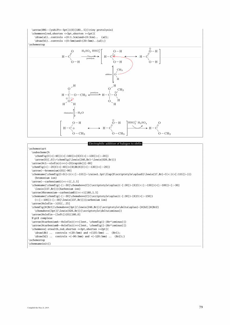
\arrow(@M1--[yshift=-5pt]){0}[180,.5]{\tiny protolysis}\chemmove[red,shorten <=3pt,shorten >=1pt]{
\draw(a1)..controls +(0:1.5cm)and+(0:3cm).. (a2);\draw(b1)..controls +(0:5mm)and+(20:5mm)..(a3);}
\schemestop
H C
O
O H
H2SO4 HSO4
H C
O H⊕
O H
H C
⊕O H
O H
H
O
CH3
addition
H C
OH
⊕O
CH3
HOH
protolysis
H C
OH
O CH3⊕O
H H
−H2Oelimination
H C
O H
⊕
O CH3
H C
⊕O H
O CH3
HSO4 H2SO4
H C
O
O CH3
protolysis
Electrophilic addition of halogen to olefin
\schemestart\subscheme{%
\chemfig{C(<[:40])(<[:160])=[6]C(<[:-130])<[:-20]}\arrow{0}[,0]\+\chemfig{\lewis{246,Br}-\lewis{026,Br}}}
\arrow(@c1--olefin){<=>[*{0}rapide]}[-90]\chemfig{>[:-20]C(<[:40])=[@{db}6]C(<[:-130])<[:-20]}\arrow(--bromonium){0}[-90]\chemname{\chemfig{C*3((<)(<:[:-155])-\raise1.5pt\llap{$\scriptstyle\oplus$}\lewis{17,Br}-C(<:)(<[:155])-)}}
{bromonium ion}\arrow(--carbeniumA){<<->}[,1.5]\chemname{\chemfig{-[:-30]\chemabove{C}{\scriptstyle\oplus}(-[:30])-[6]C(<:[:-150])(<[:-100])-[:-30]
\lewis{157,Br}}}{Xarbenium ion}\arrow(@bromonium--carbeniumB){<<->}[180,1.5]\chemname{\chemfig{-[:-30]\chemabove{C}{\scriptstyle\oplus}(-[:30])-[6]C(<[:-150])
(<:[:-100])-[:-30]\lewis{137,Br}}}{carbenium ion}\arrow(@olefin--){0}[,.25]\chemfig{@{Br1}\chemabove[3pt]{\lewis{246,Br}}{\scriptstyle\delta\oplus}-[@{b2}]@{Br2}
\chemabove[3pt]{\lewis{026,Br}}{\scriptstyle\delta\ominus}}\arrow(@olefin--[left]){0}[180,0]$\pi$ complexe\arrow(@carbeniumA--@olefin){<=>[lent, \chemfig{{-}Br^\ominus}]}\arrow(@carbeniumB--@olefin){<=>[lent, \chemfig{{-}Br^\ominus}]}\chemmove[-stealth,red,shorten <=3pt,shorten >=2pt]{
\draw(db) .. controls +(20:5mm) and +(135:5mm) .. (Br1);\draw(b2) .. controls +(-90:5mm) and +(-120:5mm) .. (Br2);}
\schemestop\chemnameinit{}
Compiled the May 21, 2019. 79
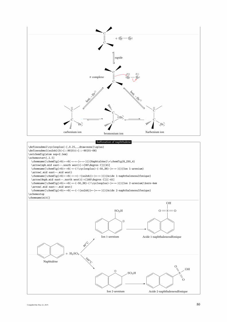
C
C
+ Br Br
rapide
C
C
C
⊕Br
C
bromonium ion
⊕C
C
Br
Xarbenium ion
⊕C
C
Br
carbenium ion
δ⊕Br
δBrπ complexe
lent, −
Br
lent,−B
r
Sulfonation of naphthalene
\definesubmol\cycleoplus{-[,0.25,,,draw=none]\oplus}\definesubmol{so2oh}{S(=[::90]O)(=[::-90]O)-OH}\setchemfig{atom sep=2.5em}\schemestart[,1.5]
\chemname{\chemfig{*6(=-*6(-=-=-)=-=-)}}{Naphtalène}\+\chemfig{H_2SO_4}\arrow(nph.mid east--.south west){->[80\degres C]}[45]\chemname{\chemfig{*6(=-*6(-=-(!\cycleoplus)-(-SO_3H)-)=-=-)}}{Ion 1-arenium}\arrow(.mid east--.mid west)\chemname{\chemfig{*6(=-*6(-=-=(-!{so2oh})-)=-=-)}}{Acide 1-naphthalenesulfonique}\arrow(@nph.mid east--.north west){->[160\degres C]}[-45]\chemname{\chemfig{*6(=-*6(-=-(-SO_3H)-(!\cycleoplus)-)=-=-)}}{Ion 2-arenium}\kern-4em\arrow(.mid east--.mid west)\chemname{\chemfig{*6(=-*6(-=-(-!{so2oh})=-)=-=-)}}{Acide 2-naphthalenesulfonique}
\schemestop\chemnameinit{}
Naphtalène
+ H2SO4
80
◦ C
⊕
SO3H
Ion 1-arenium
SO O
OH
Acide 1-naphthalenesulfonique
160 ◦
C
SO3H⊕
Ion 2-arenium
S
O
O
OH
Acide 2-naphthalenesulfonique
Compiled the May 21, 2019. 80
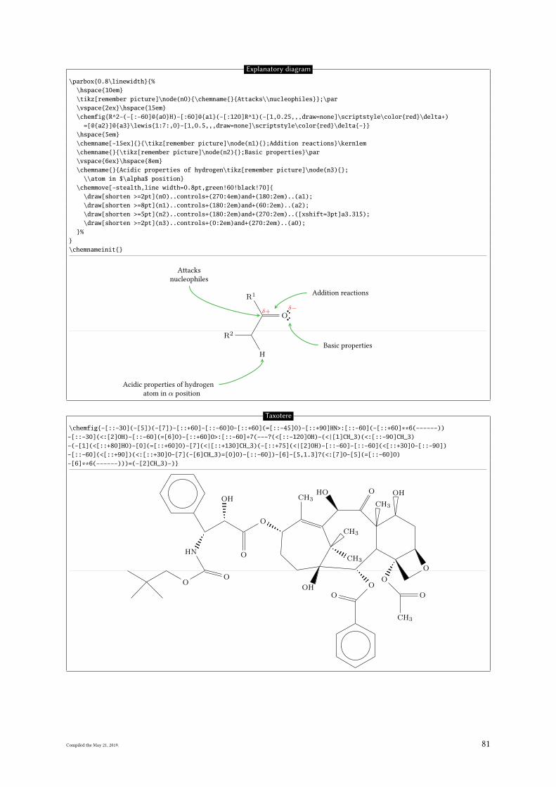
Explanatory diagram
\parbox{0.8\linewidth}{%\hspace{10em}\tikz[remember picture]\node(n0){\chemname{}{Attacks\\nucleophiles}};\par\vspace{2ex}\hspace{15em}\chemfig{R^2-(-[:-60]@{a0}H)-[:60]@{a1}(-[:120]R^1)(-[1,0.25,,,draw=none]\scriptstyle\color{red}\delta+)
=[@{a2}]@{a3}\lewis{1:7:,O}-[1,0.5,,,draw=none]\scriptstyle\color{red}\delta{-}}\hspace{5em}\chemname[-15ex]{}{\tikz[remember picture]\node(n1){};Addition reactions}\kern1em\chemname{}{\tikz[remember picture]\node(n2){};Basic properties}\par\vspace{6ex}\hspace{8em}\chemname{}{Acidic properties of hydrogen\tikz[remember picture]\node(n3){};
\\atom in $\alpha$ position}\chemmove[-stealth,line width=0.8pt,green!60!black!70]{
\draw[shorten >=2pt](n0)..controls+(270:4em)and+(180:2em)..(a1);\draw[shorten >=8pt](n1)..controls+(180:2em)and+(60:2em)..(a2);\draw[shorten >=5pt](n2)..controls+(180:2em)and+(270:2em)..([xshift=3pt]a3.315);\draw[shorten >=2pt](n3)..controls+(0:2em)and+(270:2em)..(a0);
}%}\chemnameinit{}
Attacks
nucleophiles
R2
H
R1
δ+Oδ−
Addition reactions
Basic properties
Acidic properties of hydrogen
atom in α position
Taxotere
\chemfig{-[::-30](-[5])(-[7])-[::+60]-[::-60]O-[::+60](=[::-45]O)-[::+90]HN>:[::-60](-[::+60]**6(------))-[::-30](<:[2]OH)-[::-60](=[6]O)-[::+60]O>:[::-60]*7(---?(<[::-120]OH)-(<|[1]CH_3)(<:[::-90]CH_3)-(-[1](<[::+80]HO)-[0](=[::+60]O)-[7](<|[::+130]CH_3)(-[::+75](<|[2]OH)-[::-60]-[::-60](<[::+30]O-[::-90])-[::-60](<[::+90])(<:[::+30]O-[7](-[6]CH_3)=[0]O)-[::-60])-[6]-[5,1.3]?(<:[7]O-[5](=[::-60]O)-[6]**6(------)))=(-[2]CH_3)-)}
OO
NH
OH
O
O
HO
CH3
CH3
OH O
CH3
OH
O
O
CH3
O
O
O
CH3
Compiled the May 21, 2019. 81


![ChemFig - nagel-net.de• \usepackage{chemfig} with LATEX; • \usemodule[chemfig] with ConTEXt. In all cases, the tikz package, if not loaded before, is loaded by ChemFig. The most](https://img.pdfslide.net/doc/110x75/5e5ac4f26060ef19761e848d/chemfig-nagel-netde-a-usepackagechemfig-with-latex-a-usemodulechemfig.jpg)