Embed Size (px)
Citation preview

CHEMTUBE® PPSS SERIES
BOOK NO. WT.490.200.001.UA.IM.1107

WT.490.200.001.UA.IM.1107
CHEMTUBE® PPS - S SERIES
EQUIPMENT SERIAL NO. _____________________________
DATE OF START-UP ________________________________
START-UP BY ____________________________________
Promptserviceavailablefromnationwideauthorizedservicecontractors.
ORDERING INFORMATION
Inorderforustofillyourorderimmediatelyandcorrectly,pleaseordermaterialbydescriptionandpartnumber,asshowninthisbook.Also,pleasespecifytheserialnumberoftheequipmentonwhichthepartswillbeinstalled.
WARRANTY
Sellerwarrantsforaperiodofoneyearaftershipmentthattheequipmentormaterialofitsmanufactureisfreefromdefectsinworkmanshipandmaterials.Corrosionorotherdecompositionbychemicalactionisspecificallyexcludedasadefectcoveredhereunder,exceptthisexclusionshallnotapplytochlorinationequipment.Sellerdoesnotwarrant(a)damagecausedbyuseoftheitemsforpurposesotherthanthoseforwhichtheyweredesigned,(b)damagecausedbyunauthorizedattachmentsormodifications,(c)productssubjecttoanyabuse,misuse,negligenceoraccident,(d)productswherepartsnotmade,supplied,orapprovedbySellerareusedandinthesolejudgementoftheSellersuchuseaffectstheproducts’performance,stabilityorreliability,and(e)productsthathavebeenalteredorrepairedinamannerinwhich,inthesolejudgementofSeller,affectstheproducts’performance,stabilityorreliability.SELLER MAKES NO OTHER WARRANTY OF ANY KIND, AND THE FOREGOING WARRANTY IS IN LIEU OF ALL OTHER WARRANTIES, EXPRESS OR IMPLIED, INCLUD-ING ANY WARRANTY OF MERCHANTABILITY OR OF FITNESS OF THE MATERIAL OR EQUIPMENT FOR ANY PARTICULAR PURPOSE EVEN IF THAT PURPOSE IS KNOWN TO SELLER. IfBuyerdiscoversadefectinmaterialorworkmanship,itmustpromptlynotifySellerinwriting;SellerreservestherighttorequirethereturnofsuchdefectivepartstoSeller,transporta-tionchargesprepaid,toverifysuchdefectbeforethiswarrantyisapplicable.InnoeventshallsuchnotificationbereceivedbySellerlaterthan13monthsafterthedateofshipment.Noactionforbreachofwarrantyshallbebroughtmorethan15monthsafterthedateofshipmentoftheequipmentormaterial.
LIMITATION OF BUYER’S REMEDIES. The EXCLUSIVE REMEDY foranybreachofwarrantyisthereplacementf.o.b.ship-pingpointofthedefectivepartorpartsofthematerialorequipment.Anyequipmentormaterialrepairedorreplacedunderwarrantyshallcarrythebalanceoftheoriginalwarrantyperiod,oraminimumofthreemonths.Sellershallnotbeliableforanyliquidated,special,incidentalorconsequentialdamages,includingwithoutlimitation,lossofprofits,lossofsavingsorrevenue,lossofuseofthematerialorequipmentoranyassociatedmaterialorequipment,thecostofsubstitutematerialorequipment,claimsofthirdparties,damagetoproperty,orgoodwill,whetherbaseduponbreachofwarranty,breachofcontract,negligence,stricttort,oranyotherlegaltheory;provided,however,thatsuchlimitationshallnotapplytoclaimsforpersonalinjury.
StatementsandinstructionssetforthhereinarebaseduponthebestinformationandpracticesknowntoSiemensWaterTechnologiesCorp.,butitshouldnotbeassumedthateveryacceptablesafetyprocedureiscontainedherein.Ofnecessitythiscompanycannotguaranteethatactionsinaccordancewithsuchstatementsandinstructionswillresultinthecompleteeliminationofhazardsanditassumesnoliabilityforaccidentsthatmayoccur.
1.010-42
Water Technolgies1901 West Garden Road, Vineland, NJ 08360
s

WT.490.200.001.UA.IM.1107
CHEMTUBE® PPS - S SERIES
INTRODUCTION
ThisinstructionbookconsistsofTechnicalData,Installation,Op-eration,andMaintenanceinformationfortheWallace&TiernanChemtube®PPSSSeriesPumps.
TheChemtube®PPSSSeriespumpisapositivedisplacementperi-stalticpumpsystemdesignedtohandleawidevarietyofchemicalsandliquids.Simpleoperationconsistsoftworotatingrollersthatgraduallycompressanelastomerichose,forcingliquidjustaheadofeachroller.Thehosesnapsbacktoitsoriginalshapeaftertherollerspass,refillingwithliquidforthenextdischargerevolution.Thepumpliquidonlycomesincontactwiththehoseinteriorandtheendfittings.WARNING: TO AVOID POSSIBLE SEVERE PERSONAL INJURY OR DAMAGE TO THE EQUIPMENT, THIS EQUIPMENT SHOULD BE INSTALLED, OPERATED, AND SERVICED ONLY BY TRAINED, QUALI-FIED PERSONNEL WHO ARE THOROUGHLY FAMILIAR WITH THE ENTIRE CONTENTS OF THIS INSTRUCTION BOOK.
NOTE: When ordering material, always specify model and serial number of apparatus.
Table Of Contents
VeryImportantSafetyPrecautions.................... SP-1,-2PreventiveMaintenanceSchedule..................... 1.010-13NotesonProtectiveEquipmentandClothing..... 1.010-6RegionalOffices............................................... 1.010-1TechnicalData.................................................. Section1Installation....................................................... Section2Operation......................................................... Section3Service............................................................. Section4Illustrations...................................................... Section5SparePartsList................................................. Section6
Introd.
!

WT.490.200.001.UA.IM.1107
CHEMTUBE® PPS - S SERIES
SP-1
VERY IMPORTANT SAFETY PRECAUTIONS
Thispageprovidesveryimportantsafetyinformationrelatedtosafetyininstallation,operation,andmaintenanceofthisequipment.
WARNING
TOAVOIDPOSSIBLESEVEREPERSONALINJURYOREQUIPMENTDAMAGE,OBSERVETHEFOLLOWING:
THISEQUIPMENTHANDLESHAZARDOUSMATERIALSWHICHCANCAUSESEVEREPERSONALINJURY.THISEQUIPMENTSHOULDBEINSTALLED,OPERATED,ANDSERVICEDONLYBYTRAINED,QUALIFIEDPERSONNELWHOARETHOROUGHLYFAMILIARWITHTHEENTIRECONTENTSOFTHISINSTRUCTIONBOOK.TURNOFFANDLOCKOUTPOWERBEFORESERVICINGTOAVOIDSHOCKHAZARDAND/ORPERSONALINJURY.USERIGIDPIPEWHENPUMPINGHAZARDOUSMATERIALSORATHIGHFLUIDTEMPERATURESORATHIGHDISCHARGEPRESSURES.
OBTAINSAFETYINFORMATIONFROMTHECHEMICALSUPPLIERANDREFERTOTHEINSTRUC-TIONBOOKFORFURTHERDETAILS.USEPERSONALPROTECTIVEEQUIPMENTRECOMMENDEDBYTHECHEMICALSUPPLIER.
PINCHHAZARD.DONOTREMOVEFRONTCOVER.
USEONLYSIEMENSWATERTECHNOLOGIESLISTEDPARTSEXCEPTFORCOMMERCIALLYAVAILABLEPARTSWHICHAREIDENTIFIEDBYCOMPLETEDESCRIPTIONONPARTSLIST.THEUSEOFUNLISTEDPARTSCANRESULTINEQUIPMENTMALFUNCTIONSHAVINGHAZARDOUSCONSEQUENCES.
DONOTDISCARDTHISINSTRUCTIONBOOKUPONCOMPLETIONOFINSTALLATION.INFORMA-TIONPROVIDEDISESSENTIALFORPROPER&SAFEOPERATIONANDMAINTENANCE.
ADDITIONALORREPLACEMENTCOPIESOFTHISINSTRUCTIONBOOKAREAVAILABLEFROM:
SiemensWaterTechnologiesCorp.1901WestGardenRoadVineland,NewJersey08360Phone:(856)507-9000Fax:(856)507-4125

WT.490.200.001.UA.IM.1107
CHEMTUBE® PPS - S SERIES
VERY IMPORTANT SAFETY PRECAUTIONS (CONT’D)
NOTE
MinorpartnumberchangesmaybeincorporatedintoWallace&Tiernan®productsfromtimetotimethatarenotimmediatelyreflectedintheinstructionbook.Ifsuchachangeapparentlyhasbeenmadeinyourequipmentanddoesnotappeartobereflectedinyourinstructionbook,contactyourlocalSiemensWaterTechnologiessalesofficeforinformation.
Pleaseincludetheequipmentserialnumberinallcorrespondence.Itisessentialforeffectivecommunicationandproperequipmentidentification.
SP-2

WT.490.200.001.UA.IM.1107
CHEMTUBE® PPS - S SERIES
PREVENTIVE MAINTENANCE SCHEDULE AND RECORD OF PERFORMANCE
Thisequipmentshouldreceivepreventivemaintenanceonaone(1)yearcycle.*Itisrecom-mendedthatthefollowingtablebeusedtoplan,schedule,andrecordthisimportantwork.
*NOTE: This is the recommended cycle. Your local operating conditions may call for more frequent preventive maintenance.
1.010-13
PROTECT YOUR EQUIPMENT INVESTMENT
MINIMIZE DOWNTIME
ORDER A PREVENTIVE MAINTENANCE KIT NOW ... KEEP ONE ON HAND
Date of Installation
Serial No. Pin No.
Preventive Maintenance Log
Schedule Date Date Performed

WT.490.200.001.UA.IM.1107
CHEMTUBE® PPS - S SERIES
NOTES ON PROTECTIVE EQUIPMENT AND CLOTHING
ThefollowingWarningappearsinseverallocationsinthisbook.Itisgeneralinnatureduetothevarietyofhazardousliquidsthisequipmentiscapableofhandling.
WARNING: WHEN DEALING WITH HAZARDOUS MATERIAL, IT IS THE RESPONSIBILITY OF THE OPERATOR TO OBTAIN AND FOLLOW ALL SAFETY PRECAUTIONS RECOMMENDED BY THE MATERIAL MANUFACTURER/SUPPLIER.
It is good general practice to make use
of protective equipment when handling
any hazardous material.
IT IS RECOMMENDED THAT SUCH PROTEC-
TIVE EQUIPMENT BE USED BY ALL PERSONS
SERVICING THIS PUMP, ASSOCIATED PIP-
ING, TUBING, VALVES, AND ACCESSORIES,
WHEN THE EQUIPMENT IS HANDLING ANY
HAZARDOUS MATERIAL.
1. Goggles,flexiblefitting,hoodedventilation(perANSIZ87.1)
2. FaceShield(perANSIZ87.1)
3. ChemicalApron
4. ChemicalGloves
NOTE: (1)ANSIZ87.1“practiceforoccupational.......eyeandfaceprotection”recommendsgoggles(#1above)asthe“preferredprotection”whenhandlingchemicalsthatpresentahazardfromsplash,acidburnsorfumes;forsevereexposure,afaceshield(#2above)overthegogglesisrecommended.
(2) An eye flushing fountain and a deluge-type shower may be recommended orrequiredbyinsurancecarriersorgovernmentalsafetyagencies,whichshouldbeconsultedforspecificrequirements.
1.010-6

WT.490.200.001.UA.IM.1107
CHEMTUBE® PPS - S SERIES
REGIONAL OFFICES
INSTALLATION, OPERATION, MAINTENANCE, AND SERVICE INFORMATION
DirectanyquestionsconcerningthisequipmentthatarenotansweredintheinstructionbooktotheResellerfromwhomtheequipmentwaspurchased.IftheequipmentwaspurchaseddirectlyfromSiemensWaterTechnologiesCorp.,Vineland,NJ,contacttheofficeindicatedbelow.
UNITED STATES
1901WestGardenRoadVineland,NJ08360TEL:(856)507-9000FAX:(856)507-4125
CANADA
IftheequipmentwaspurchaseddirectlyfromSiemensWaterTechnologiesCanada,Inc.,contactthenearestofficeindicatedbelow.
ONTARIO QUEBEC
250RoyalCrestCourt 243Blvd.BrienMarkham,Ontario Bureau210L3R3S1 Repentigny,Quebec(905)944-2800 (450)582-4266
1.010-1

WT.490.200.001.UA.IM.1107 �
CHEMTUBE® PPS - S SERIES
SECTION � - TECHNICAL DATA
List of Contents
PARA. NO.
Technical Data .......................................... 1.1Operating Principle ................................... 1.2Optional Components............................... 1.3Tubular Element ....................................... 1.4Model S Gear Reducers ............................. 1.5Illustrations Models S5 & S10 Capacity Chart ............. 490.200.190.010A&B Model S16 Capacity Chart ...................... 490.200.190.020A&B Model S26 Capacity Chart ...................... 490.200.190.030A&B

WT.490.200.001.UA.IM.1107 �
CHEMTUBE® PPS - S SERIES
�.� Technical Data
Type Peristaltic hose pump
Models S5A, S5B,S10A, S10B, S16A, S16B, S26A, S26B
Service Metering or transfer of most liquids, in-cluding corrosive fluids, polyelectrolytes, and slurries.
Capacity range Refer to Dwgs. 490.200.190.010, 490.200.190.020, and 490.200.190.030.
Maximum liquid temp. 167° F - Buna N tubular185° F - Natural Isoprene tubular200° F - EPDM tubular185° F - Hypalon
Maximum back pressure30 PSI: S26A50 PSI: S10A, S16A60 PSI: S5A120 PSI: S5B, S10B, S16B, S26B
Suction lift 28 feet of water
Tubular material Natural Isoprene (Natural rubber)Ethylene propylene (EPDM)*Nitrile Butadene (Buna N)Hypalon
Compatibility Refer to Compatibility Guide (WT.490.200.000.IE.CG)
Drive unit Right-angle worm gear reducer
Variable speed Inverter motor with VFD: 10:1 turn-down ratio
Connection sizes S5 & S10: ½" NPTS16: ¾" NPTS26: 1¼" NPT
Connection material PVC for pressure up to 90 PSI316SS for pressure up to 120 PSITitanium for pressure up to 120 PSI
Leak detector (stan-dard)
Dry contact rating 100VA max.,250 VAC max.
* Not available on S5.

WT.490.200.001.UA.IM.1107 �
CHEMTUBE® PPS - S SERIES
�.� Operating Principle
The tubular element is progressively compressed by the rollers. The alternating compression and relaxation of the tubular element generates continuous fluid suction and delivery. Dry operation, i.e., the pump is empty, does not cause any damage.
Figure �.� - Flow Diagram
The moving mechanical parts are protected by guards that can be removed only by mechanical disassembly. During use, all parts of the pump must be correctly fitted.
Movement of the rollers is protected by the transparent cover (26) as shown in Figure 1.2.
Collapse of the tubular element (44) due to fatigue may cause leak-age of the pumped liquid. Adopt the precautions given in paragraph 2.3, Pipe Installation - Flooded Suction.
Figure �.� - Mechanical Parts
CAUTION: The pump is a positive displacement-type: valves closed in the discharge line will cause overpressure. (Refer to paragraph �.�, Pipe Installation - Pressure Relief Valve, for more information.)

WT.490.200.001.UA.IM.1107 �
CHEMTUBE® PPS - S SERIES
WARNING: ALL OPERATIONS REqUIRING OPENING OF THE ELECTRICAL CONTROL PANEL AND/OR OPENING OF THE MOTOR TERMINAL bOARD bOx (ELECTRICAL PARTS), MUST bE CARRIED OUT by TRAINED PERSONNEL.
�.� Optional Components • Pulsation dampener• In-line pressure relief valve• Calibration column
NOTE: Refer to Section 6 - Spare Parts List at the end of this manual for optional components part numbers and specifications.
�.� Tubular Element
The tubular element determines the use and limits of the peri-staltic pump.
Figure �.� - Tubular Element
Optimum choice depends on many factors:
• Chemical compatibility• Operating pressure • Operating temperature • Pump revolutions • Suction capacity • Duty cycle • Durability expected • Compatibility with food products
The factory must be informed of the application when the order is placed. For non-scheduled fluids or conditions, consult the factory.
CAUTION: Dispose of the used tubular elements properly. They can be considered solid urban refuse and classified as special refuse if they contain toxic-harmful pollution due to the pumped fluid.

WT.490.200.001.UA.IM.1107 �
CHEMTUBE® PPS - S SERIES
�.� Model S Gear Reducers
�.�.� Right-Angle Fixed Speed Gearbox
Only the right-angle gearbox is offered on S Series models (see Figure 1.4). The input and output shaft are at 90° angles with each other. Speed ratio is made possible by different worm shaft and worm gear combinations. They come filled with synthetic oil and do not require any oil changes, therefore there is no oil fill plug or oil drain plug. A flange is provided for mounting the gearbox. The pump rotor shaft engages the hollow worm through a key to the drive.
Figure �.� - Fixed Speed Gearbox and Variable Speed Gearbox

WT.490.200.001.UA.IM.1107 6
CHEMTUBE® PPS - S SERIES
CHEMTUBE® PPS - MODELS S5 & S10 - CAPACITY CHART
490.200.190.010AISSUE 1 3-05
S�0 Mechanical Variable Speed Capacity Chart
RPM�0 PSI 60 PSI ��0 PSI HP
Ind (Inverter)Duty Cycle
GPH LPH GPH LPH GPH LPH6-36 2.4-13 8.9-48.8 2.2-12 8.2-45 1.9-10.5 7.2-39.4 1/4 (1/2)
Continuous8-45 3-16.5 11.2-62 2.7-15.5 10.5-58.1 2.4-13.5 9.2-50.6 1/4 (1/2)
11-63 4.4-24 16.4-90 4-22 15-82.5 3.6-20 13.6-75 1/4 (1/2)Intermittent*
23-125 8.5-46.5 32-174.4 8-44 30-165 7.3-40 27.3-150 1/4 (1/2)
* Intermittent Duty: Max. 1 hour running; Min. 1 hour off
S� & S�0 Fixed Speed Capacity Chart
RPM�0 PSI 60 PSI ��0 PSI
HP Ind (Inv/SCR)
Duty cycleS�GPH (LPH)
S�0GPH (LPH)
S�GPH (LPH)
S�0GPH (LPH)
S�GPH (LPH)
S�0GPH (LPH)
17.5 1.8 (6.8) 6.5 (24.6) 1.7 (6.4) 5.5 (21) 1.5 (6) 4.5 (17) 1/4 (1/2)
Continuous25 2.6 (9.8) 9.5 (35.9) 2.5 (9.5) 8.5 (32.2) 2.2 (8.3) 7 (26.5) 1/4 (1/2)
292.84
(10.8)11 (41) 2.8 (10.8) 9 (34) 2.5 (9.5) 8.5 (32.2) 1/4 (1/2)
38 3.9 (14.6) 14 (53) 3.8 (14.3) 13 (49) 3.4 (12.8) 11 (43) 1/2 (1/2
Intermittent*
50 5.1 (19.3) 18.8 (71) 5 (19) 17 (64) 4.4 (16.6)15.5
(58.7)1/2 (1/2
62.5 6.4 (24.2)23.5
(88.9)6.3 (23) 22 (83) 5.6 (21) 19.5 (73) 1/2 (1/2
87.5 8.9 (33.7) 32.8 (124) 8.7 (33) 31 (117.3) 7.8 (29.5) 28 (105) 1/2 (1/2125 – 47 (174) – 44 (165) – 40 (150) 1/2 (1/2)

WT.490.200.001.UA.IM.1107 �
CHEMTUBE® PPS - S SERIES
CHEMTUBE® PPS - MODEL S5 - CAPACITY CHART
490.200.190.010BISSUE 1 3-05
NOTE: SELECT MAxIMUM CAPACITy DESIRED. FOLLOW HORIZONTAL LINE FROM THAT POINT ACROSS TO bACK PRESSURE LINE CLOSEST TO CUSTOMER CONDITIONS* THEN VERTICALLy TO RPM LINE. (RECOMMENDED CONTINUOUS RPM SHOULD bE bELOW �0 FOR LONGER HOSE LIFE.)
* FOR bACK PRESSURES THAT FALL bETWEEN THOSE INDICATED, IT IS RECOMMENDED THE NExT HIGHEST VALUE bE USED.
CA
PAC
ITY
- G
PH
PUMP SPEED - RPM
CA
PAC
ITY
- G
PH
490.200.190.010BIssue 1 3-05
PUMP SPEED - RPM
NOTE: SELECT MAXIMUM CAPACITY DESIRED. FOLLOW HORIZONTAL LINE FROM THAT POINT ACROSS TO BACK PRESSURE LINE CLOSEST TO CUSTOMER CONDITIONS* THEN VERTICALLY TO RPM LINE. (RECOMMENDED CONTINUOUS RPM SHOULD BE BELOW 30 FOR LONGER HOSE LIFE.)
* FOR BACK PRESSURES WHICH FALL BETWEEN THOSE INDICATED, IT IS RECOMMENDED THE NEXT HIGHEST VALUE BE USED.
Continuous Duty
Intermittent Duty (1 Hour on/1 Hour off )
0
30 PSI 60 PSI
120 PSI
30 PSI 60 PSI
120 PSI

WT.490.200.001.UA.IM.1107 �
CHEMTUBE® PPS - S SERIES
CHEMTUBE® PPS - MODEL S5 - CAPACITY CHART
490.200.190.010CISSUE 1 3-05
NOTE: SELECT MAxIMUM CAPACITy DESIRED. FOLLOW HORIZONTAL LINE FROM THAT POINT ACROSS TO bACK PRESSURE LINE CLOSEST TO CUSTOMER CONDITIONS* THEN VERTICALLy TO RPM LINE. (RECOMMENDED CONTINUOUS RPM SHOULD bE bELOW �0 FOR LONGER HOSE LIFE.)
* FOR bACK PRESSURES THAT FALL bETWEEN THOSE INDICATED, IT IS RECOMMENDED THE NExT HIGHEST VALUE bE USED.
CHEMTUBE PPS - MODEL S10
54
52 30 PSI
50 60 PSI
48
46 120 PSI 44
42
40
38
36
34
CA
PAC
ITY
- G
PH
32
30
28
26
24
22
20
18
16
14
12
10
8
6
4
2
0 10 20 30 40 50 60 70 80 90 100 110 120 130 140PUMP SPEED - RPM
Continuous Duty Intermittent Duty(1 Hour on/1 Hour off)
CN493.120

WT.490.200.001.UA.IM.1107 �
CHEMTUBE® PPS - S SERIES
CHEMTUBE® PPS - MODEL S16 - CAPACITY CHART
490.200.190.020AISSUE 0 5-01
S�6 Fixed Speed Capacity Chart
RPM�0 PSI 60 PSI ��0 PSI HP
Ind (Inverter)Duty Cycle
GPH LPH GPH LPH GPH LPH17.5 25 93.8 20 75 15 56.3 1/4 (1/2)
Continuous25 36 135 31 116.3 25 93.7 1/4 (1/2)29 40 150 35 131.3 30 112.5 1/4 (1/2)38 53 198.8 46 172.5 40 150 1/4 (1/2)50 73 273.8 64 243.8 58 217.5 1/4 (1/2)
62.5 90 337.5 83 311.2 75 281.3 1/4 (1/2)Intermittent*87.5 127 476.3 117 438.8 105 393.8 1/4 (1/2)
125 180 675 170 637.5 155 581.5 1/4 (1/2)
S�6 Mechanical Variable Speed Capacity Chart
RPM�0 PSI 60 PSI ��0 PSI HP
Ind (Inverter)Duty Cycle
GPH LPH GPH LPH GPH LPH
6-36 9.5-52 35.5-195 8.4-4631.4-172.5
7.3-40 27.3-150 1/4 (1/2)Continuous
8-45 11.8-65 44.3-244 12-60 41-225 9.5-52 35.5-195 1/4 (1/2)11-63 16.7-92 62.7-345 11.8-85 58-319 13.6-75 51-282 1/4 (1/2)
Intermittent*23-125 32.7-180
122.7-675
31-170 116-638 28-153104.4-
5741/4 (1/2)
* Intermittent Duty: Max. 1 hour running; Min. 1 hour off

WT.490.200.001.UA.IM.1107 �0
CHEMTUBE® PPS - S SERIES
CHEMTUBE® PPS - MODEL S16 - CAPACITY CHART
490.200.190.020BISSUE 0 5-01
NO
TE:
SELE
CT
MA
xIM
UM
CA
PAC
ITy
DES
IRED
. FO
LLO
W H
ORI
ZON
TAL
LIN
E FR
OM
TH
AT
POIN
T A
CRO
SS T
O b
AC
K P
RESS
URE
LIN
E C
LOSE
ST T
O C
UST
OM
ER
CO
ND
ITIO
NS*
TH
EN V
ERTI
CA
LLy
TO
RPM
LIN
E. (
REC
OM
MEN
DED
CO
NTI
NU
OU
S RP
M S
HO
ULD
bE
bELO
W �
0 F
OR
LON
GER
HO
SE L
IFE.
)
* FO
R bA
CK
PRE
SSU
RES
THA
T FA
LL b
ETW
EEN
TH
OSE
IND
ICA
TED
, IT
IS R
ECO
MM
END
ED T
HE
NEx
T H
IGH
EST
VALU
E bE
USE
D.
205 30 PSI
200
195 60 PSI
190
185
180
175 120 PSI
170
165
160
155
150
145
140
135
130
125
120
CA
PAC
ITY
- G
PM
115
110
105
100
95
90
85
80
75
70
65
60
55
50
45
40
35
30
25
20
15
10
5
0 10 20 30 40 50 60 70 80 90 100 110 120 130 140PUMP SPEED - RPM
Continuous service Intermittent service(1 Hour on/1 Hour off)

WT.490.200.001.UA.IM.1107 ��
CHEMTUBE® PPS - S SERIES
CHEMTUBE® PPS - MODEL S26 - CAPACITY CHART
490.200.190.030AISSUE 0 5-01
S�6 Fixed Speed Capacity Chart
RPM�0 PSI 60 PSI �0 PSI ��0 PSI
Duty CycleGPH LPH HP GPH LPH HP GPH LPH HP GPH LPH HP
17.5 115 435.3 1/2 (1) 87 329.3 1/2 (1) 75 283.9 1/2 (1) 65 246 1 (1½)
Continuous
22 140 529.9 1/2 (1) 120 454.2 1/2 (1) 115 435.3 1/2 (1) 90 340.7 1 (1½)27 175 662.4 1/2 (1) 150 567.8 1/2 (1) 120 454.2 1/2 (1) 110 416.4 1 (1½)39 235 889.5 1/2 (1) 215 813.8 1/2 (1) 190 719.2 1/2 (1) 175 662.4 1 (1½)46 280 1060 1/2 (1) 250 946.3 1/2 (1) 230 870.6 1/2 (1) 220 832.7 1 (1½)58 350 1324.8 1/2 (1) 320 1211.2 1 (1½) 300 1135.5 1 (1½) X X X73 430 1627.6 1/2 (1) 410 1551.9 1 (1½) 380 1438.3 1 (1½) X X X
Intermittent*92 550 2082 1/2 (1) 520 1968.2 1 (1½) 460 1741.1 1 (1½) X X X
117 680 2573.8 1/2 (1) 650 2460.3 1 (1½) 580 2195.3 1 (1½) X X X140 820 3104 1/2 (1) 780 2952.3 1 (1½) 705 2668.4 1 (1½) X X X
S�6 Mechanical Variable Speed Capacity Chart
RPM�0 PSI 60 PSI �0 PSI ��0 PSI
HP Duty CycleGPH LPH GPH LPH GPH LPH GPH LPH
6-36 41-225 153-844 36-200 136-750 32-175 119.3-656.3 29-160 109-600 1½ (2)Continuous
8-45 47.3-260 117-975 42-230 157-863 39-215 146.6-806.3 36.4-200 136-750 1½ (2)11-63 69-380 259-1425 66-365 249-1369 X X X X 1½ (2)
Intermittent*23-125
133-730 496-2738 X X X X X X 1½ (2)
( ) denotes HP of Inverter duty motor * Intermittent Duty: Max. 1 hour running; Min. 1 hour off

WT.490.200.001.UA.IM.1107 ��
CHEMTUBE® PPS - S SERIES
CHEMTUBE® PPS - MODEL S26 - CAPACITY CHART
490.200.190.030BISSUE 0 5-01
NO
TE:
SELE
CT
MA
xIM
UM
CA
PAC
ITy
DES
IRED
. FO
LLO
W H
ORI
ZON
TAL
LIN
E FR
OM
TH
AT
POIN
T A
CRO
SS T
O b
AC
K P
RESS
URE
LIN
E C
LOSE
ST T
O C
UST
OM
ER
CO
ND
ITIO
NS*
TH
EN V
ERTI
CA
LLy
TO
RPM
LIN
E. (
REC
OM
MEN
DED
CO
NTI
NU
OU
S RP
M S
HO
ULD
bE
bELO
W �
0 F
OR
LON
GER
HO
SE L
IFE.
)
* FO
R bA
CK
PRE
SSU
RES
THA
T FA
LL b
ETW
EEN
TH
OSE
IND
ICA
TED
, IT
IS R
ECO
MM
END
ED T
HE
NEx
T H
IGH
EST
VALU
E bE
USE
D.
850
825 30 PSI
800 60 PSI
775
750 90 PSI
725
700
675
650
625
600
575
550
525
CA
PAC
ITY
- G
PH
500
475
450
425
400
375
350
325
300
275
250
225 120 PSI
200
175
150
125
100
75
50
25
0 10 20 30 40 50 60 70 80 90 100 110 120 130 140PUMP SPEED - RPM
Continuous Duty Intermittent Duty(1 Hour on/1 Hour off)

WT.490.200.001.UA.IM.1107 ��
CHEMTUBE® PPS - S SERIES
SECTION � - INSTALLATION
List of Contents
PARA. NO.
Transport, Storage, and Lifting ....................... 2.1Typical Installation ......................................... 2.2 Inspection .................................................. 2.2.1 Space for Operating and Maintenance ......... 2.2.2 Piping ......................................................... 2.2.3 Pump Mounting .......................................... 2.2.4Pipe Installation ............................................. 2.3Illustrations Models S5 & S10 Dimensions ...................... 490.200.100.010 Model S16 Dimensions ............................... 490.200.100.020 Model S26 Dimensions ............................... 490.200.100.030

WT.490.200.001.UA.IM.1107 ��
CHEMTUBE® PPS - S SERIES
�.� Transport, Storage, and Lifting
• Transport
The pump is protected by its packing consisting of a hard base (pallet) and cardboard wrapping.
NOTE: The packing materials are recyclable.
During transport, the roller is set to the rest position (see Figure 2.1).
Figure �.� - Pump Transport
• Storage
The roller must be set to the rest position.
Open, exposed, and excessively damp areas must not be used for storage.
For storage periods of over 60 days, protect any coupling surfaces (flanges for reducers or motors) with suitable anti-oxidizing products.
CAUTION: The spare tubular elements must be stored in a dry place sheltered from direct sunlight.

WT.490.200.001.UA.IM.1107 ��
CHEMTUBE® PPS - S SERIES
• Lifting
Model S26 may require lifting equipment. The components of Models S5, S10, and S16 are comparatively light.
Pump Model
bare Shaft Pump
with base
Right Angle
Gearbox
Inverter Duty
Motor
S5, S10 18 lbs. 5 lbs.32 lbs.
(1/2 HP)
S16 27 lbs. 5 lbs.53 lbs. (1 HP)
S26 77 lbs. 14 lbs.62 lbs.
(1½ HP)
�.� Typical Installation
�.�.� Inspection
Having removed the pump from its packing, check that the pump has not been grazed or damaged.
Check that the power supply voltage corresponds to the motor voltage.
Check the piping connection to the pump.
Check that the type of tubular element is suitable for the fluid to be pumped. If the fluid pumped has a constant temperature of over 60° C, the walls of the pump will reach temperatures which make them dangerous to touch and suitable warnings or guards must therefore be provided.
The electrical control panel and the connection cables must comply with local electrical codes. (The panel must be preset to invert the rotational direction of the motor, if necessary.)
If the command and control panel is remote, a start button and a stop-emergency button (which cannot be cut off from the panel) must be fitted near the pump to be used for maintenance. The pump should be “off” and “locked out” from its source of power prior to performing any electrical maintenance.

WT.490.200.001.UA.IM.1107 �6
CHEMTUBE® PPS - S SERIES
�.�.� Space for Operating and Maintenance
The pump must be positioned to ensure adequate accessibility to the tubular element, as well as other parts that require routine maintenance. See Figure 2.2 for clearance recommendations.
Figure �.� - Minimum Clearance Requirements
As a general rule, the pump must be installed in a ventilated place well away from sources of heat. If the pump must be installed outdoors, shelter must be provided to protect it from inclement weather and direct sunlight.
�.�.� Piping
The pump must be as close as possible to the fluid source so that the suction pipe is as short and straight as possible.
• Suction Line
The suction piping must be perfectly airtight. It must be made of material that cannot be crushed by the internal vacuum and is compatible with the fluid being handled.
NOTE: The minimum diameter must be equal to that of the tubular element; viscous fluids require larger diameters.
The pump is self-priming; no foot valve is needed.

WT.490.200.001.UA.IM.1107 ��
CHEMTUBE® PPS - S SERIES
• Discharge Line
To reduce the power absorbed, use pipes as short and straight as possible. The diameter will be equal to the rated pump diameter unless specific calculations require otherwise. Viscous fluids re-quire larger diameters. The discharge line piping must be made of material that is compatible with the fluid being handled.
NOTE: Connect the fixed pipes to the pump with a UNION or FLANGE to facilitate maintenance. Attach the pipes securely and avoid loads on the pump or piping.
NOTE: The flow pulsates slightly - the pulsations increase as the number of revolutions and the pressure increase.
If there is the risk of the pulsations damaging the pipes or dis-turbing the utilities downstream, suitable pulsation dampen-ers must be fitted. Refer to Section 6 - Spare Parts List at the end of this manual for pulsation dampener part numbers and specifications.
�.�.� Pump Mounting
The pump is supplied with a metal frame and must be bolted se-curely to the base.
�.� Pipe Installation
• Minimum suction distance – Lay the delivery pipe sloping to-wards the outlet. (See Figure 2.3.)
Figure �.� - Optimum Layout for Fluids

WT.490.200.001.UA.IM.1107 ��
CHEMTUBE® PPS - S SERIES
• Flooded suction – Fit a safety device that will cut in if the tubular element breaks. For corrosive or dangerous substances, provide a retaining compartment. (See Figure 2.4.)
Figure �.� - Layout for Viscous Products, Flooded Suction
• Pressure Relief Valve – If there is the possibility of a valve being closed on the discharge pipe, provide a pressure relief valve. The same danger can exist on the suction piping in the event of inverse rotation. (See Figure 2.5.)
Figure �.� - Pressure Relief Valve

WT.490.200.001.UA.IM.1107 ��
CHEMTUBE® PPS - S SERIES
• Pump at a standstill – With “H” above 13 feet (four meters), the fluid causes the pump to rotate backwards, flowing back in the pipe towards the suction line. Avoid this problem with self-braking motors, variable frequency drives, or single-acting valves. (See Figure 2.6.)
Figure �.6 - Pump at a Standstill
NOTE: To avoid leakages and/or flooding of the machine sta-tor, the system should be provided with the tubular element leak detector. Refer to paragraph �.�, Tubular Element Leak Detector, for more information on using a tubular element leak detector.

WT.490.200.001.UA.IM.1107 �0
CHEMTUBE® PPS - S SERIES
CHEMTUBE® PPS - MODELS S5 & S10 - DIMENSONS
490.200.100.010ISSUE 2 9-07
10-9/16"(268)
3-15/32"(88)
3-5/32"(80)
19"(483)
APPROX.
9-1/16"(230)
4-13/32"(112)
8-9/32"(210)
NOTE: ALL DIMS. IN ( ) ARE mm.
6-5/16"(160)
3-11/16"(94)
10-11/32"(263)
9-7/32"(234)
5-3/4"(146)
7-7/8"(200)
1-1/4"(32) 6-3/16"
(157)
BASE
LEAK DETECTOR100VA MAX.250VAC, 2.5 AMPS(6-1/2 FT.CABLE SUPPLIED)
MOTOR
1/2" NPT
Ø3/8"(9)4 HOLES

WT.490.200.001.UA.IM.1107 ��
CHEMTUBE® PPS - S SERIES
CHEMTUBE® PPS - MODEL S16 - DIMENSONS
490.200.100.020ISSUE 2 9-07
MOTOR
3/4" NPT
NOTE: ALL DIMS. IN ( ) ARE mm.
20-25/32"(528)
APPROX.
10-27/32"(275)
12-27/32"(326)
11-13/16"(300)
6-13/16"(173)
4-23/32"(120)
4-11/32"(110)
Ø3/8"(9)4 HOLES
6-5/16"(160)BASE
9-1/16"(230)
10"(254)
7-7/8"(200)
6-31/32"(177)
1-15/32"(37)
6-21/32"(169)
3-5/32"(80)
LEAK DETECTOR100VA MAX.250VAC, 2.5 AMPS(6-1/2 FT.CABLE SUPPLIED)

WT.490.200.001.UA.IM.1107 ��
CHEMTUBE® PPS - S SERIES
CHEMTUBE® PPS - MODEL S26 - DIMENSONS
490.200.100.030ISSUE 2 9-07
NOTE: ALL DIMS. IN ( ) ARE mm.
BASE
15-11/32"(390)
16-5/8"(422)
6-15/16"(176)
8-15/16"(227)
10-1/32"(255)
4-7/16"(113)
10-5/8"(270)
13-1/16"(332)
2-5/32"(55) 6-31/32"
(177)
24-13/32"(620)
APPROX.
13-15/32"(342)
4"(102)
14-3/16"(360)
8-21/32"(220)
Ø7/16"(11)4 HOLES
LEAK DETECTOR100VA MAX250VAC, 2.5 AMPS(6-1/2 FT.CABLE SUPPLIED)
MOTOR
1-1/4"NPT

WT.490.200.001.UA.IM.1107 ��
CHEMTUBE® PPS - S SERIES
SECTION � - OPERATION
List of Contents
PARA. NO.
Starting ............................................................ 3.1Running ........................................................... 3.2Stopping .......................................................... 3.3Residual Risks ................................................... 3.4Configuration ................................................... 3.5 Altering the Configuration ............................. 3.5.1

WT.490.200.001.UA.IM.1107 ��
CHEMTUBE® PPS - S SERIES
�.� Starting
Before starting the pump, ensure that:
• The type of tubular element is suitable for the fluid to be pumped.
• The oil in the variable speed gear box (if present) is at the correct level.
• The power supply voltage corresponds to the motor voltage and electrical control panel.
• The guards are fitted on the moving parts.
• The motor thermal protection is set according to the values on the motor rating plate.
NOTE: In the case of a variable frequency drive, check that the maximum frequency that can be delivered corresponds to the maximum number of pump and motor revolutions.
• The rotation direction is as required; perform a rotation test. (Refer to Figure 1.1, Flow Diagram, in Section 1.)
• Any optional electrical components are connected to the control panel and operation has been tested.
• Delivery pressure is correct. Use a pressure gauge on the delivery line if any uncertainty exists.
�.� Running
• Set the rollers to the work position.
• Start the pump with valves open and at minimum speed (if adjustable).
• Start and stop a few times to check operation of the controls and system seal.
• If there is the danger of working with closed valves, test the efficiency of the safety devices (pressure relief valve).
• Check, in working conditions, that the flow rate, pressure, and motor current draw on three phases are correct.

WT.490.200.001.UA.IM.1107 ��
CHEMTUBE® PPS - S SERIES
• Do not change fluids without cleaning the inside of the pump; the mixture of chemicals can be highly dangerous.
• Never leave the pump full, particularly in the case of fluids that can deposit residues or polymerize or corrosive fluids that can eventually attack the tubular element.
• Do not increase the setting of the motor protections beyond the limits specified on the rating plate. If motor performance is insufficient, check the system data and contact USF/W&T technical service.
• When cleaning the pump with a stream of water, do not aim it directly at the motor or electrical equipment.
�.� Stopping
• Switch the motor off to stop the flow. The pump operates simi-lar to a pinch valve (compression of the tubular element) with the exception of the condition described in paragraph 2.3, Pipe Installation - Pump at a Standstill.
• Drainage of the pump is easy as the fluid is present only inside the tubular element: rotate the pump towards the drain pro-vided in the piping system.
• The piping and tubular element must be cleaned with fluids that are compatible with both the tubular element and the chemical being pumped.
• For prolonged standstills, follow the directions in paragraph 4.5, Long-Term Shut-Down.

WT.490.200.001.UA.IM.1107 �6
CHEMTUBE® PPS - S SERIES
�.� Residual Risks
The pump can be used for food-grade fluids if tubular elements classified for specific use with a food, stainless steel fittings, and adequate cleaning procedures are employed. The pump must not be used for food-grade fluids if these conditions are not observed.
It is not possible to accurately forecast the duration of the tubular element; therefore, precautions for breakage with leakage of the liquid must be taken in advance. The tubular element leak detector can be wired to stop the pump and to sound an alarm. In any case, if the fluid is dangerous due to corrosion or fumes, the following must be provided:
• Retaining compartments (in the case of flooded suction and/or very long deliveries).
• Adequate suction or ventilation (for fluids that can emit toxic or harmful fumes).
�.� Configuration
The capacity of the pump to supply discharge pressure depends on the compression of the tubular elements by the rollers. See Figure 3.1.
Figure �.� - Supply Configurations
There are two supply configurations that are set at the factory. For S5, S10 and S16 the roller shafts are installed into the holes marked either “4” or “8” on the rotor. For S26 two setS of spacers with “4” or “8” markings are provided.
“4” marking for operating pressures lower than 60 psi (4 Bars). “8” marking for operating pressures from 60 psi up to 120 psi (8 Bars)

WT.490.200.001.UA.IM.1107 ��
CHEMTUBE® PPS - S SERIES
The configuration used is established during assembly of the pump according to the pressure it will pump against with. Subsequent variations must be authorized by Siemens Water Technology.
The roller on S5, S10 and S16 was re-designed to incorporate ball bearings as the rolling element. A new roller shaft was re-designed as well. It is recommended to replace the older design with the ball bearing design. No replacement part is available for the older design. Retrofit kits are made available for this purpose that includes all the necessary parts and tool to do the change. For roller replace-ment only, order the Roller Kit. Instruction Sheet is also included with the Kits.
Part Number for the Kits can be found on Section 6, Paragraph 6.2.4.
�.�.� Altering the Configuration Pump Models S5, S10, and S16: Without Cover and Tubular Element.
Figure �.� - Roller Assembly, ball bearing Design
The new ball bearing design made it possible to alter the configu-ration in two ways; repositioning the screw to the holes with the corresponding number of dots and by installing the roller shafts in the rotor to the holes with either markings of “4” or “8”. See Figure 3.2.
Shown below are the resulting operating pressures:
Rotor PositioningScrew
RollerAssembly
EccentricShaft
Roller Stop PinOrientation
Rotor PositioningScrew
RollerAssembly
EccentricShaft
Roller Stop PinOrientation

WT.490.200.001.UA.IM.1107 ��
CHEMTUBE® PPS - S SERIES
4
8
0 PSI
Below60 PSI
60 TO 120PSI
120 to 180PSI
Below60 PSI
60 TO 120PSI
pos1 pos2 pos3ROLLER
ROTOR
rolle
r
pin into rotor
The standard location of the positioning screw is at the holes with two dots (Position 2) and the roller shafts are installed in either holes with markings of “4” or “8”. The roller is riding on an eccentric, and if the positioning screw is screwed at the holes with two dots (Position 2) the roller is on the center of the roller shafts. This design enables us to change the configuration without the disassembly of the rotor. With the combination of the roller shaft location “4” and “8” holes on the rotor, as shown above it is possible to easily configure the pump to operate at a higher operating pressure. However, by doing so, the life of the tube will be shortened. It is always recommended to configure the pump at the lowest operat-ing pressure as required.
Remove the roller stop pins and slide the rollers out.Verify the marking of the holes in the rotor where the roller shaft is installed.Refer to the operating pressure shown above relocate the po-sitioning screw accordingly.Install the roller and secure with the roller stop pin. Refer to Figure 3.2 for the proper orientation of the pins.Reassemble.
NOTE: If the roller shaft has to be relocated, refer to Paragraph �.�, Removal and Installation of Roller Assembly, for instruction on roller and rotor disassembly and installations.
a.b.
c.
d.
e.

WT.490.200.001.UA.IM.1107 ��
CHEMTUBE® PPS - S SERIES
Pump Models S26: Without Tubular Element (See Figure 3.3)
Dismantle the support roller by removing two hex bolts.Dismantle the spacer and replace it with the one marked “8”) Part No. AAB8945) or “4” (Part No. AAB7943).Reassemble.
Figure �.� - Pump Type S�6: Without Tubular Element
a.b.
c.

WT.490.200.001.UA.IM.1107 �0
CHEMTUBE® PPS - S SERIES
WT.490.200.001.UA.IM.1107 ��
CHEMTUBE® PPS - S SERIES
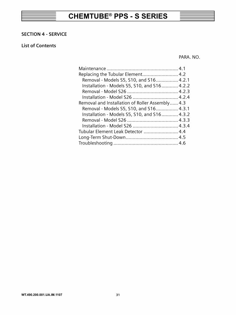
SECTION � - SERVICE
List of Contents
PARA. NO.
Maintenance .................................................... 4.1Replacing the Tubular Element .......................... 4.2 Removal - Models S5, S10, and S16 ................ 4.2.1 Installation - Models S5, S10, and S16 ............ 4.2.2 Removal - Model S26 ..................................... 4.2.3 Installation - Model S26 ................................. 4.2.4Removal and Installation of Roller Assembly ...... 4.3 Removal - Models S5, S10, and S16 ................ 4.3.1 Installation - Models S5, S10, and S16 ............ 4.3.2 Removal - Model S26 ..................................... 4.3.3 Installation - Model S26 ................................. 4.3.4Tubular Element Leak Detector ......................... 4.4Long-Term Shut-Down ...................................... 4.5Troubleshooting ............................................... 4.6

WT.490.200.001.UA.IM.1107 ��
CHEMTUBE® PPS - S SERIES
�.� Maintenance
All work on the pump must be carried out with the pump at a standstill and the power disconnected.
The only component subject to normal wear is the tubular element, which must therefore be periodically replaced.
The tubular element must be lubricated at initial assembly with the spray lubricant supplied.
Lubricate the hose once a week (or approximately every 100 op-erating hours) with the supplied spray lubricant.
CAUTION: Use only the supplied spray lubricant on the tubular element. Other lubricants will damage the tubular element.
Figure �.� - Area to be Lubricated
Periodically (approximately every 100 working hours) check that the wall of the stator where the tubular element rests is slightly lubricated. If necessary, inject a small amount of the supplied spray lubricant.
WARNING: bEFORE OPENING THE PUMP, ENSURE THAT THE PIPING IS EMPTy. ANy FLUID COLUMN COULD CAUSE THE MACHINE TO ROTATE.
�.� Replacing the Tubular Element
�.�.� Tubular Element Removal - Models S�, S�0, and S�6 (See Figure �.�)
NOTE: This procedure applies only to a pump that has been in operation.
a. Jog the rotor so that one roller (18) is at the 2 o’clock position.
b. Disconnect the power to the pump at the control box.
c. If water-flushing connection is available, flush as follows; if not, go to Step c1 and proceed to Step d.

WT.490.200.001.UA.IM.1107 ��
CHEMTUBE® PPS - S SERIES
1) Close the suction and discharge valve and open the drain valve, to relieve the system pressure.
2) Remove the transparent cover (1) by removing the four acorn nuts (22).
3) Remove the roller assembly that is at the 2 o’clock position by removing the retaining pin (30) and pulling out the roller assembly (18).
4) Temporarily install the transparent cover, (1).
5) Turn the power to the pump and jog the rotor so that the other roller (18) is not in contact with the tubular element (33).
6) Turn off the power at the control box.
7) Open the flushing valve, if the tubular element (33) is leak-ing, water will be collected inside the pump housing and will drain through the leak detector drain line.
8) Close the water-flushing valve.
d. Disconnect the suction and discharge line connection to the system.
e. Remove one side of the top clamping bracket (32), by unscrew-ing two bolts.
NOTE: Clamping bracket (��) comes in a pair with the same marking stamped at the ends.
NOTE: On S�, there are half clamps on each of the clamping brackets. Do not lose them. See Dwg. ��0.�00.000.��0A (��).
NOTE: The two bolts are shorter and must only be installed at the same location.
f. Slice the tubular element (33) about 2" long at the connection end. Be careful not to damage the PVC connection (31).
g. Pull the connection (31) out of the tubular element (33) and set it aside.

WT.490.200.001.UA.IM.1107 ��
CHEMTUBE® PPS - S SERIES
h. Remove one side of the bottom-clamping bracket (32) and pull the connection (31) and the tubular element (33) out together.
i. Remove the second connection (31) by following Step f.
j. Clean the inside of the pump housing completely, including the transparent cover (1) and the connections.
k. Clean the leak detector as follows:
1) Carefully pull the probe and cover assembly from the housing.
2) Pull down the bottom cover.
3) Clean all of the parts thoroughly.
4) Assembly is the reverse of the disassembly.
Figure �.� - Replacing the Tubular Element: Models S�, S�0, and S�6
�.�.� Tubular Element Installation - Models S�, S�0, and S�6 (See Figure �.�)
a. Lubricate the connection (31) and insert it into one end of the tubular element (33) all the way against the shoulder.
b. Lubricate the outer wall of the tubular element (33) along the area that will be in contact with the housing and the rollers (18).
c. Insert the end of the tubular element (33) without the connec-tion (31) through the bottom opening. Slide the tubular element around the stator housing and out through the top opening.
d. Position the connection properly into the first half of the clamp-

WT.490.200.001.UA.IM.1107 ��
CHEMTUBE® PPS - S SERIES
ing bracket (32), and install the second half. Ensure that the correct pair is installed and in the proper orientation.
e. On S5, position the half clamps into the clamping brackets. See Dwg. 490.200.000.110A (47).
f. Secure the clamping bracket (32) with the two shorter bolts.
g. Lubricate the other connection (31) and insert it into the top end of the tubular element (33), then repeat Steps d and e for the top clamping bracket.
h. Tighten all of the bolts. (S5 and S10: M6 bolts, torque to 75 ft-lbs. S16: M8 bolts, torque to 16 ft-lbs.)
i. Install the transparent cover (1) temporarily and turn the power on.
j. Turn the rotor so that the roller shaft without the roller assembly is at the 2 o'clock position. Turn the power off and remove the transparent cover (1).
k. Install the roller assembly (18) and secure by the roller stop pin (30).
l. Install the transparent cover (1). Do not over tighten the four acorn nuts (22).
m. Reconnect the suction and discharge lines. Close the drain valve, and then open the suction and discharge valves.
n. Turn the power on.
�.�.� Tubular Element Removal - Model S�6 (See Figure �.�)
NOTE: This procedure applies only to a pump that has been in operation
a. Jog the rotor so that one roller is at the 2 o’clock position.
b. Disconnect the power to the pump at the control box.
c. If water-flushing connection is available, flush as follows; if not, go to Step c1 and proceed to Step d.
1) Close the suction and discharge valve and open the drain valve, to relieve the system pressure.

WT.490.200.001.UA.IM.1107 �6
CHEMTUBE® PPS - S SERIES
Figure �.� - Replacing the Tubular Element: Model S�6

WT.490.200.001.UA.IM.1107 ��
CHEMTUBE® PPS - S SERIES
2) Remove the transparent cover (2) by removing the four acorn nuts (24).
3) Remove the roller assembly that is at the 2 o’clock position.
4) Temporarily install the transparent cover, (2).
5) Turn the power to the pump and jog the rotor so that the other roller is not in contact with the tubular element.
6) Turn off the power at the control box.
7) Open the flushing valve, if the tubular element is leaking, water will be collected inside the pump housing and will drain through the leak detector drain line.
8) Close the water-flushing valve.
d. Disconnect the suction and discharge line connection to the system.
e. Remove one side of the top clamping bracket, (30), by unscrew-ing two M10x50 bolts, (28).
NOTE: Clamping bracket (�0) comes in a pair with the same marking stamped at the ends.
NOTE: The two bolts, (��), are shorter and must only be installed at the same location.
f. Slice the tubular about 2" long at the connection end. Be careful not to damage the PVC connection.
g. Pull out the connection from the tubular element and set it aside.
h. Remove one side of the bottom-clamping bracket (30) and pull out the connection and the tubular element together.
i. Remove the second connection by following Step f.
j. Clean the inside of the pump housing completely, including the transparent cover (2) and the connections.
k. Clean the leak detector as follows:

WT.490.200.001.UA.IM.1107 ��
CHEMTUBE® PPS - S SERIES
1) Carefully pull the probe and cover assembly from the housing.
2) Pull down the bottom cover.
3) Clean all of the parts thoroughly.
4) Assembly is the reverse of the disassembly.
�.�.� Tubular Element Installation - Model S�6 (See Figure �.�)
a. Lubricate the connection and insert it into one end of the tubular element all the way against the shoulder.
b. Lubricate the outer wall of the tubular element along the area that will be in contact with the housing and rollers.
c. Insert the end of the tubular element without the connection through the bottom opening. Slide the tubular element around the stator housing and out through the top opening.
d. Position the connection properly into the first half of the clamp-ing bracket (30), and install the second half. Ensure that the correct pair is installed and in the proper orientation.
e. Secure the clamping bracket (30) with the two shorter bolts (28).
f. Lubricate the other connection (31) and insert it into the top end of the tubular element (33), then repeat Steps d and e for the top clamping bracket.
g. Tighten all of the M10 bolts, (28) and (31). Torque to 31 ft-lbs.
h. Install the transparent cover (2) temporarily and turn the power on.
i. Turn the rotor so that the end without the roller is at the 2 o’clock position. Turn the power off. Remove the transparent cover (2).
j. Install the other roller assembly, noting that the side with the double nut must be to the inside of the pump.
k. Install the transparent cover (2). Do not over tighten the acorn nuts, (24).
l. Reconnect the suction and discharge lines. Close the drain valve,

WT.490.200.001.UA.IM.1107 ��
CHEMTUBE® PPS - S SERIES
and then open the suction and discharge valves.
m. Turn the power on.
4.3 Removal and Installation of Roller Assembly
�.�.� Roller Assembly Removal - Models S�, S�0, and S�6 (See Figure �.�)
a. Jog the rotor so that one roller is at the 3 o’clock position.
b. Disconnect the power to the pump at the control box.
c. Disassemble the transparent cover by removing the four acorn nuts and washers.
d. Remove the roller assembly that is at the 2 o’clock position by re-moving the roller stop pin and pulling out the roller assembly.
e. Temporarily install the transparent cover.
f. Turn on the power to the pump and jog the rotor so that the other roller is in the 2 o’clock position and not in contact with the tubular element.
g. Turn off the power at the control box and remove the transpar-ent cover again.
h. Repeat procedure in Step d.
i. Assembly is the reverse of disassembly. Ensure that the position-ing screw is installed into the holes marked with two dots (Posi-tion 2) for standard configurations.
j. Secure the rollers with the roller stop pins. Refer to Figure 3.2 for proper pin orientation.
k. Replace the transparent cover and tighten the four acorn nuts.

WT.490.200.001.UA.IM.1107 �0
CHEMTUBE® PPS - S SERIES
Figure �.� - Roller Assembly, Roller Shaft and Rotor
�.�.� Roller Shafts Removal and Installations - Models S�, S�0, and S�6 (See Figure �.�)
a. Remove the tubular element as described in Section 4.2.1.
b. Remove the roller assembly as described in Section 4.3.1.
c. Unscrew the four hex bolts located around the center post and pull out the rotor. The screw in the center post can also be tightened clockwise to "jack" the rotor out.
d. Clean the rotor, secure it in a vise and remove the two roller shafts and discard. Note the location of the roller shafts. They are opposite its other and can be either in the holes marked "4" or "8". Refer to Figure 4.5. Take note of the location.
e. Position the roller shafts opposite its other to the holes marked "4" or "8" as noted in the disassembly procedure d above.
f. Install the washer and the nut. Tighten the nut slightly by hand.
g. Secure the rotor in a vise, refer to Figure 4.5, position the tool to orient the roller shaft in the correct position and keep them from turning. Note that the holes marked "4" or "8" in the tool match with holes marked "4" or "8" on the rotor. Tighten the nut 10-12 ft. lbs. and remove the tool.
h. Once the roller shafts are properly secured to the rotor, install the rotor assembly into the center shaft using the four hex bolts.
Positioning Screwat Position 2
Rotor
Roller Stop Pin
Roller Assembly
Roller Shaft at "4"
Positioning Screwat Position 2
Rotor
Roller Stop Pin
Roller Assembly
Roller Shaft at "4"

WT.490.200.001.UA.IM.1107 ��
CHEMTUBE® PPS - S SERIES
i. Install the roller assembly per Section 433.1 and the tubular element per Section 4.2.1.
j. Replace the transparent cover and tighten the four acorn nuts.
Figure �.� - Installation of the Roller Shafts
4.3.3 Roller Assembly Removal - Model S26 (See Figure 4.6)
Figure �.6 - Roller/bracket Assembly: Model S�6
Roller Shaft
Washer
Nut
Tool
Roller Shaft
Washer
Nut
Tool

WT.490.200.001.UA.IM.1107 ��
CHEMTUBE® PPS - S SERIES
a. Jog the rotor so that one roller is at the 3 o’clock position.
b. Disconnect the power to the pump at the control box.
c. Disassemble the transparent cover by removing the four acorn nuts and washers.
d. Remove the roller bracket assembly that is at the 3 o’clock po-sition by first removing two hex bolts which secure the roller bracket to the rotor.
e. Temporarily install the transparent cover.
f. Turn on the power to the pump and jog the rotor so that the other roller is in the 3 o’clock position, and not in contact with the tubular element.
g. Turn off the power at the control box and remove the transpar-ent cover again.
h. To remove the roller assembly from the bracket, simply loosen two hex nuts on one end and remove the bolt from the bracket and roller. Inspect the roller assemblies for defects or looseness. Replace as required. A kit is available (part no. AAC7937) to re-build one pump.
i. Assemble the new roller and bracket using existing hardware from the pump; i.e., one hex bolt, two washers, and two hex nuts. Be sure to tighten both nuts against one another to prevent the roller assembly from loosening during operation.

WT.490.200.001.UA.IM.1107 ��
CHEMTUBE® PPS - S SERIES
4.3.4 Roller Assembly Installation - Model S26 (See Figure 4.7)
a. Jog the rotor so that one end is at the 3 o’clock position, if not done so already.
b. When installing the roller/bracket assembly onto the rotor, be sure to mount it with the nuts on the bolt facing the inside of the housing, or with the head of the bolt facing towards you. Use two existing hex bolts and washers in the center holes of the bracket to secure the assembly to the end of the rotor, using the additional holes in the bracket to guide it over the alignment pins, one on top and one on the bottom.
c. Temporarily install the transparent cover.
d. Turn on the power to the pump and jog the rotor so that the other end of the rotor is in the 3 o’clock position, and not in contact with the tubular element.
e. Turn off the power at the control box and remove the transpar-ent cover again.
f. Repeat procedures found in Steps b and c.
g. Replace the transparent cover and tighten the four acorn nuts.
Figure �.� - Roller Assembly: Model S�6

WT.490.200.001.UA.IM.1107 ��
CHEMTUBE® PPS - S SERIES
�.� Tubular Element Leak Detector (See Figure �.�)
This is a safety device that can be wired to stop the motor or sound an alarm if the tubular element breaks and the fluid leaks out inside the pump. It does not require any maintenance, but it is good prac-tice to periodically ensure that the float is free to move. The probe is integral with the cover (46). The liquid can be emptied from the unit by removing the plug (48) below the support (49). An overflow connection is provided to direct the fluid to a container.
NOTE: The leak detector is not suitable for use with flammable fluids.
Figure �.� - Tubular Element Leak Detector

WT.490.200.001.UA.IM.1107 ��
CHEMTUBE® PPS - S SERIES
�.�.� Wiring the Leak Detector
It is recommended that the leak detector be wired to stop the pump in case of a leak. It is also possible to wire the leak detector to sound an alarm or turn the lights on to indicate a leak. The leak detector is a normally closed float switch with dry contact. A six-foot cable with two #20 wires is provided for connection to a relay or VFD controller. See Figure 4.9 for the wiring for an induction motor installation. Refer to the VFD instruction manual for wiring the leak detector to the controller for stopping the motor.
Figure �.� - Leak Detector Wiring

WT.490.200.001.UA.IM.1107 �6
CHEMTUBE® PPS - S SERIES
�.� Long-Term Shut-Down (See Figure �.�0)
If the pump is out of use for longer than one month, ensure that the tubular element is not unnecessarily stressed by setting the roller to the rest position.
a. Turn the rotor until one of the rollers is free from contact with the tubular element.
b. Disconnect the power.
c. Unscrew the acorn nuts (22) and remove the transparent cover (1).
d. Remove the retaining pin (30) and pull out the roller assembly (18). Slide the roller assembly into the central pin (13/14) of the rotor (16).
e. Replace the transparent cover and tighten the four acorn nuts.
f. Reconnect the power.
g. Turn the rotor until the tubular element is free.
Figure �.�0
NOTE: The roller bearings are lubricated for life.

WT.490.200.001.UA.IM.1107 ��
CHEMTUBE® PPS - S SERIES
�.6 Troubleshooting
The following troubleshooting table is provided for determining and correcting most common troubles.
Table �.� - Troubleshooting
PRObLEMS CAUSES SOLUTIONSTHE PUMP DOES NOT PRIME.
The pump has been left inac-tive for a long time without observing the procedure in paragraph 4.5.
Leave the pump running for a short time, after which it will return to full efficiency.If the problem occurs when pumping from underground tanks, the pump must first be used to pump from a tank above ground.
The suction pipe is collapsed, one of its internal linings has become detached or the pipe is clogged.
In addition to satisfying the requirements of paragraph 2.2.3, the bottom of the suc-tion pipe must be fitted with a rigid coupling to guarantee complete opening.
POOR PERFORMANCE. Air enters from the suction pipe.
Check for damage and check the pipe gaskets.
Suction pipe too long. Adhere as close as possible to the specifications given in paragraph 2.2.3.
High gas content in the liq-uid pumped.
Consult Technical Service.
ExCESSIVE WEAR OF THE TUbULAR ELEMENT
Incompatibility of the fluid to the tubular element.
Refer to the compatibility guide.
Temperature of the fluid too high.
Lower the fluid temperature.
Back pressure too high. Check for any resistance on the discharge line.
Not enough lubrication or wrong spray lubricant.
Follow lubrication schedule and use proper spray lubricant.
RPM too high. Check the motor revolution. It must not exceed 1750 rpm. Consult Technical Service.
Roller is not turning. Attain the kit to rebuild the roller assembly.

WT.490.200.001.UA.IM.1107 ��
CHEMTUBE® PPS - S SERIES
Table �.� - Troubleshooting (Cont'd)
PRObLEMS CAUSES SOLUTIONSPIPES SHAKE. Insufficient gas cushion in
pulsation dampeners.Consult Technical Service.
Suction pipe kinked. Consult Technical Service.ExCESSIVE HEATING OF ELECTRICAL MOTOR.
NOTE: First check the cur-rent draw on the three phases and compare it with the values on the motor rating plate.
System too demanding for motor.
Consult Technical Service.
Electrical cables too long or with insufficient size.
Consult Technical Service.
Drop in power supply voltage or unbalanced phases.
Consult Technical Service.
Insufficient ventilation. Ensure that the motor fan is integral with the shaft.
NOISES AND RATTLING IN-SIDE THE PUMP.
Excessive suction head. Consult Technical Service.Pipes kinked. Consult Technical Service.Pipes with insufficient diam-eters.
Consult Technical Service.
NOTE: For any problems not included in the above list, contact the Siemens Water Technologies Technical Service.

WT.490.200.001.UA.IM.1107 ��
CHEMTUBE® PPS - S SERIES
WARNING LABELS
The following warnings are attached to the equipment.
-------------------------------------------------------------------------------------AAb����: THIS EQUIPMENT HANDLES HAZARDOUS MATERIALS
WHICH CAN CAUSE SEVERE PERSONAL INJURY. THIS EQUIPMENT SHOULD BE INSTALLED, OPERATED, AND SERVICED ONLY BY TRAINED, QUALIFIED PERSONNEL WHO ARE THOROUGHLY FAMILIAR WITH THE ENTIRE CONTENTS OF THIS INSTRUCTION BOOK. TURN OFF AND LOCK OUT POWER BEFORE SERVICING TO AVOID SHOCK HAZARD AND/OR PERSONAL INJURY. USE RIGID PIPE WHEN PUMPING HAZARDOUS MATERIALS OR AT HIGH FLUID TEMPERATURES OR AT HIGH DISCHARGE PRESSURES.
-------------------------------------------------------------------------------------AAb����: OBTAIN SAFETY INFORMATION FROM THE CHEMICAL
SUPPLIER AND REFER TO THE INSTRUCTION BOOK FOR FURTHER DETAILS. USE PERSONAL PROTECTIVE EQUIP-MENT RECOMMENDED BY THE CHEMICAL SUPPLIER.
-------------------------------------------------------------------------------------AAb���0: PINCH HAZARD. DO NOT REMOVE FRONT COVER.
-------------------------------------------------------------------------------------

WT.490.200.001.UA.IM.1107 �0
CHEMTUBE® PPS - S SERIES

WT.490.200.001.UA.IM.1107 ��
CHEMTUBE® PPS - S SERIES
SECTION � - ILLUSTRATIONS
List of Contents
DWG. NO.
Parts S5 & S10 Pump ...................................... 490.200.000.110A&B S16 Pump .............................................. 490.200.000.120A&B S26 Pump .............................................. 490.200.000.130A&B S10 Gear Reducer .................................. 490.200.000.140 S16 Gear Reducer .................................. 490.200.000.150 S26 Gear Reducer .................................. 490.200.000.160

WT.490.200.001.UA.IM.1107 ��
CHEMTUBE® PPS - S SERIES
CHEMTUBE PPS - S5 & S10 PUMPS- PARTS
490.200.000.110AISSUE 2 9-07
NO
TE: F
OR
PART
S LI
ST, S
EE D
WG
. 490
.200
.000
.110
B.
WT.490.200.001.UA.IM.1107 ��
CHEMTUBE® PPS - S SERIES
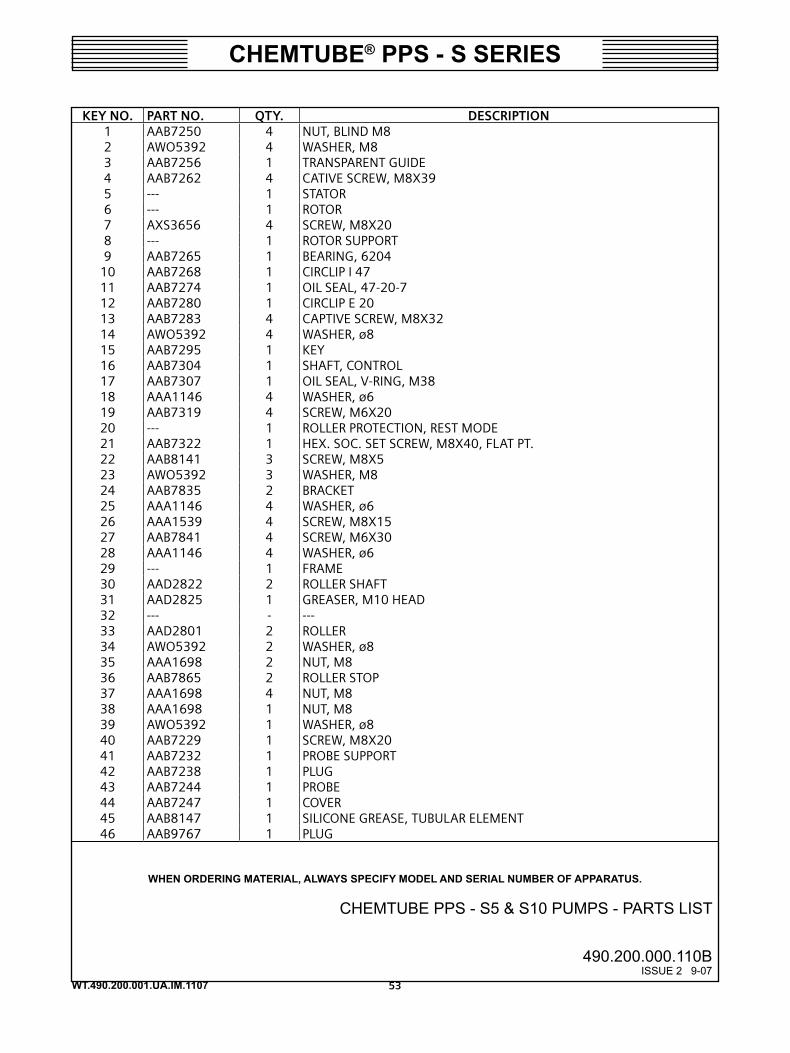
WHEN ORDERING MATERIAL, ALWAYS SPECIFY MODEL AND SERIAL NUMBER OF APPARATUS.
KEy NO. PART NO. qTy. DESCRIPTION1 AAB7250 4 NUT, BLIND M82 AWO5392 4 WASHER, M83 AAB7256 1 TRANSPARENT GUIDE4 AAB7262 4 CATIVE SCREW, M8X395 --- 1 STATOR6 --- 1 ROTOR7 AXS3656 4 SCREW, M8X208 --- 1 ROTOR SUPPORT9 AAB7265 1 BEARING, 6204
10 AAB7268 1 CIRCLIP I 4711 AAB7274 1 OIL SEAL, 47-20-712 AAB7280 1 CIRCLIP E 2013 AAB7283 4 CAPTIVE SCREW, M8X3214 AWO5392 4 WASHER, ø815 AAB7295 1 KEY16 AAB7304 1 SHAFT, CONTROL17 AAB7307 1 OIL SEAL, V-RING, M3818 AAA1146 4 WASHER, ø619 AAB7319 4 SCREW, M6X2020 --- 1 ROLLER PROTECTION, REST MODE21 AAB7322 1 HEX. SOC. SET SCREW, M8X40, FLAT PT.22 AAB8141 3 SCREW, M8X523 AWO5392 3 WASHER, M824 AAB7835 2 BRACKET25 AAA1146 4 WASHER, ø626 AAA1539 4 SCREW, M8X1527 AAB7841 4 SCREW, M6X3028 AAA1146 4 WASHER, ø629 --- 1 FRAME30 AAD2822 2 ROLLER SHAFT31 AAD2825 1 GREASER, M10 HEAD32 --- - ---33 AAD2801 2 ROLLER34 AWO5392 2 WASHER, ø835 AAA1698 2 NUT, M836 AAB7865 2 ROLLER STOP37 AAA1698 4 NUT, M838 AAA1698 1 NUT, M839 AWO5392 1 WASHER, ø840 AAB7229 1 SCREW, M8X2041 AAB7232 1 PROBE SUPPORT42 AAB7238 1 PLUG43 AAB7244 1 PROBE44 AAB7247 1 COVER45 AAB8147 1 SILICONE GREASE, TUBULAR ELEMENT46 AAB9767 1 PLUG
CHEMTUBE PPS - S5 & S10 PUMPS - PARTS LIST
490.200.000.110BISSUE 2 9-07

WT.490.200.001.UA.IM.1107 ��
CHEMTUBE® PPS - S SERIES
CHEMTUBE PPS - S16 PUMP - PARTS
490.200.000.120AISSUE 2 9-07
NO
TE: F
OR
PART
S LI
ST, S
EE D
WG
. 490
.200
.000
.120
B.

WT.490.200.001.UA.IM.1107 ��
CHEMTUBE® PPS - S SERIES
CHEMTUBE PPS - S16 PUMP - PARTS LIST
490.200.000.120BISSUE 1 3-05
WHEN ORDERING MATERIAL, ALWAYS SPECIFY MODEL AND SERIAL NUMBER OF APPARATUS.
KEy NO. PART NO. qTy. DESCRIPTION1 AAB7250 4 NUT, BLIND, M82 AWO5392 4 WASHER, ø83 AAB7874 1 TRANSPARENT GUIDE4 AAB7262 4 CAPTIVE SCREW, M8X395 --- 1 STATOR6 --- 1 ROTOR7 AAA1545 4 SCREW, M8X208 --- 1 ROTOR SUPPORT9 AAB7877 1 BEARING, 6205
10 AAB7880 1 CIRCLIP I 5211 AAB7883 1 OIL SEAL, 52-25-712 AAB7886 1 CIRCLIP E 2513 AAB7283 4 CAPTIVE SCREW, M8X3214 AWO5392 4 WASHER, ø815 AAB7295 1 KEY, 6.6.4516 AAB7889 1 CONTROL SHAFT17 AAB7892 1 OIL SEAL V-RING, ø6018 AWO5392 4 WASHER, ø819 AAA1545 4 SCREW, M8X2020 --- 1 ROLLER PROTECTION, REST MODE21 AAB7895 1 HEX. SOC. SET SCREW, M10X50, FLAT POINT22 AXS3568 3 SCREW, M8X1523 AWO5392 3 WASHER, ø824 AAB7901 2 BRACKET25 AWO5392 4 WASHER, ø826 AAA1647 4 SCREW, M8X4527 AAA1647 4 SCREW, M8X4528 AWO5392 4 WASHER, ø829 AAB8147 1 SILICONE GREASE, TUBULAR ELEMENT30 AAD2834 2 ROLLER SHAFT31 --- - ---32 --- - ---33 AAD2798 2 ROLLER34 AAA1452 2 WASHER, ø1035 ATI3434 2 NUT, M1036 AAB7865 2 ROLLER STOP37 AAA1698 4 NUT, M838 --- 1 FRAME39 AWO5392 1 WASHER, ø840 AAB7868 1 SCREW, M10X1541 AAB7247 1 COVER42 AAB8264 1 PROBE SUPORT43 AAB7244 1 PROBE44 AAV7238 1 PLUG45 AAB9767 1 PLUG46 AAD2825 1 GREASER, M10 HEAD
WT.490.200.001.UA.IM.1107 �6
CHEMTUBE® PPS - S SERIES
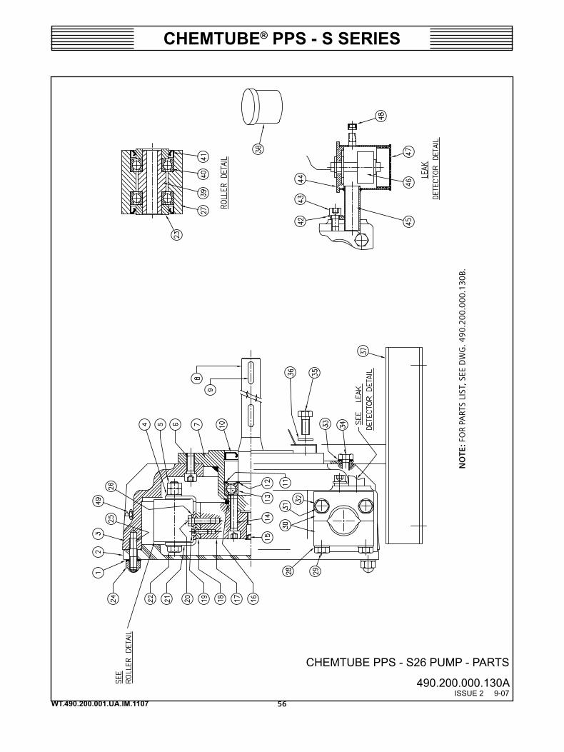
CHEMTUBE PPS - S26 PUMP - PARTS
490.200.000.130AISSUE 2 9-07
NO
TE: F
OR
PART
S LI
ST, S
EE D
WG
. 490
.200
.000
.130
B.

WT.490.200.001.UA.IM.1107 ��
CHEMTUBE® PPS - S SERIES
CHEMTUBE PPS - S26 PUMP - PARTS LIST
490.200.000.130BISSUE 2 9-07
WHEN ORDERING MATERIAL, ALWAYS SPECIFY MODEL AND SERIAL NUMBER OF APPARATUS.
KEy NO. PART NO. qTy. DESCRIPTION1 AAA1452 4 WASHER, ø102 AAB7916 1 TRANSPARENT GUIDE3 --- 1 STATOR4 AAA1452 4 WASHER, ø105 ATI3434 4 NUT, M106 ASG3667 4 SCREW, M10X257 --- 1 ROTOR SUPPORT8 AAB7919 1 CONTROL SHAFT9 AAB7922 2 KEY, 8.7.30
10 AAB7925 1 OIL SEAL, 72.35.1011 AAB7928 1 CIRCLIP I 7212 AAB7931 1 CIRCLIP E 3513 AAB7934 1 BEARING, 620714 AAB8081 4 SCREW, M10X4515 AAB7937 1 PLUG, ø10.516 AAB7892 1 OIL SEAL V-RING, V60A17 --- 1 ROTOR18 AAB7943 2 ADJUSTMENT SPACER, 4 BAR
AAB8945 2 ADJUSTMENT SPACER, 8 BAR19 AXQ3929 4 SCREW, M6X1520 AAA1593 4 SCREW, M8X2521 AAB7949 2 ROLLER SUPPORT22 AAA7785 2 SCREW, M10X9023 AAB7952 4 ROLLER SPACER24 AAB7955 4 BLIND NUT, M1025 AWO5392 4 CAPTIVE SCREW, M10X4126 AAB7958 4 WASHER, M827 ATI5686 2 ROLLER28 AAA1452 4 SCREW, M10X5029 AAB7904 4 WASHER, ø1030 AAB7904 2 BRACKET31 AAA1674 4 SCREW, M10X5532 AAA1452 4 WASHER, ø1033 AAA1452 4 WASHER, ø1034 AAA1419 3 SCREW, M10X2035 AAA1530 4 SCREW, M10X2536 AAA1452 3 WASHER, ø1037 --- 1 FRAME38 AAB8147 1 SILICONE GREASE, TUBULAR ELEMENT39 AAB7907 2 CONTROL SHAFT40 AAB7910 4 BEARING, 620341 AAB7913 4 OIL SEAL, 30.40.742 AAA1452 1 WASHER, ø1043 AAB8084 1 SCREW, M10X1544 AAB7247 1 SAFETY PROBE COVER45 AAB8264 1 SAFETY PROBE SUPPORT46 AAB7244 1 SAETY PROBE47 AAB7238 1 PLUG48 AAB9767 1 PLUG49 --- 1 GREASER, M10 HEAD

WT.490.200.001.UA.IM.1107 ��
CHEMTUBE® PPS - S SERIES
CHEMTUBE PPS - MODEL S10 GEAR REDUCER - PARTS
490.200.000.140ISSUE 0 5-01
WHEN ORDERING MATERIAL, ALWAYS SPECIFY MODEL AND SERIAL NUMBER OF APPARATUS.
S�0 Fixed Speed Capacity Chart
RPM�0 PSI 60 PSI ��0 PSI HP Ind
(Inverter)Gearbox No. Motor Frame
GPH LPH GPH LPH GPH LPH17.5 6.5 24.4 5.5 20.6 5 18.8 1/4 (1/2) AAB7394
N56C
25 9 33.8 8 30 7 26.3 1/4 (1/2) AAB739729 11 41.3 9 33.8 8 30 1/4 (1/2) AAB740038 14 52.5 12.5 46.9 11 41.3 1/4 (1/2) AAB740350 19 71.3 17 63.8 15 56.3 1/4 (1/2) AAB7406
62.5 24 90 22 82.5 19.5 73.1 1/4 (1/2) AAB740987.5 32 120 30.5 114.4 28 105 1/4 (1/2) AAB7412125 46.5 174.4 44 165 40 150 1/4 (1/2) AAB7415
S�0 Mechanical Variable Speed Capacity Chart
RPM�0 PSI 60 PSI ��0 PSI HP Ind
(Inverter)Combined Gearbox
Fxd Spd Gearbox
Vrbl Spd Gearbox
Motor FrameGPH LPH GPH LPH GPH LPH
6-36 2.4-13 8.9-48.8 2.2-12 8.2-451.9-10.5
7.2-39.4 1/4 (1/2) AAB8678 AAB7406
AAB7373 N56C8-45 3-16.5 11.2-62
2.7-15.5
10.5-58.1
2.4-13.5
9.2-50.6 1/4 (1/2) AAB8681 AAB7409
11-63 4.4-24 16.4-90 4-22 15-82.5 3.6-20 13.6-75 1/4 (1/2) AAB8684 AAB741223-125
8.5-46.5
32-174.4
8-44 30-165 7.3-4027.3-150
1/4 (1/2) AAB8687 AAB7418

WT.490.200.001.UA.IM.1107 ��
CHEMTUBE® PPS - S SERIES
CHEMTUBE PPS - MODEL S16 GEAR REDUCER - PARTS
490.200.000.150ISSUE 0 5-01
WHEN ORDERING MATERIAL, ALWAYS SPECIFY MODEL AND SERIAL NUMBER OF APPARATUS.
S�6 Fixed Speed Capacity Chart
RPM�0 PSI 60 PSI ��0 PSI HP Ind
(Inverter)Gearbox No. Motor Frame
GPH LPH GPH LPH GPH LPH17.5 25 93.8 20 75 15 56.3 1/4 (1/2) AAB7394
N56C
25 36 135 31 116.3 25 93.7 1/4 (1/2) AAB739729 40 150 35 131.3 30 112.5 1/4 (1/2) AAB740038 53 198.8 46 172.5 40 150 1/4 (1/2) AAB740350 73 273.8 64 243.8 58 217.5 1/4 (1/2) AAB7406
62.5 90 337.5 83 311.2 75 281.3 1/4 (1/2) AAB740987.5 127 476.3 117 438.8 105 393.8 1/4 (1/2) AAB7412125 180 675 170 637.5 155 581.5 1/4 (1/2) AAB7415
S�6 Mechanical Variable Speed Capacity Chart
RPM�0 PSI 60 PSI ��0 PSI HP Ind
(Inverter)Combined Gearbox
Fxd Spd Gearbox
Vrbl Spd Gearbox
Motor FrameGPH LPH GPH LPH GPH LPH
6-36 9.5-52 35.5-195 8.4-4631.4-172.5
7.3-40 27.3-150 1/4 (1/2) AAB8678 AAB7406
AAB7373 N56C8-45 11.8-65 44.3-244 12-60 41-225 9.5-52 35.5-195 1/4 (1/2) AAB8681 AAB7409
11-63 16.7-92 62.7-34511.8-
8558-319
13.6-75
51-282 1/4 (1/2) AAB8684 AAB7412
23-125
32.7-180
122.7-675
31-170 116-638 28-153104.4-
5741/4 (1/2) AAB8687 AAB7418

WT.490.200.001.UA.IM.1107 60
CHEMTUBE® PPS - S SERIES
CHEMTUBE PPS - MODEL S26 GEAR REDUCER - PARTS
490.200.000.160ISSUE 0 5-01
WHEN ORDERING MATERIAL, ALWAYS SPECIFY MODEL AND SERIAL NUMBER OF APPARATUS.
NOTE: ( ) DENOTES HP OF INVERTER MOTOR.
S�6 Fixed Speed Capacity Chart
RPM�0 PSI 60 PSI �0 PSI ��0 PSI Gearbox
No.Motor FrameGPH LPH HP GPH LPH HP GPH LPH HP GPH LPH HP
17.5 115 435.3 1/2 (1) 87 329.3 1/2 (1) 75 283.9 1/2 (1) 65 246 1 (1½) AAB7421
N145TC
22 140 529.9 1/2 (1) 120 454.2 1/2 (1) 115 435.3 1/2 (1) 90 340.7 1 (1½) AAB742427 175 662.4 1/2 (1) 150 567.8 1/2 (1) 120 454.2 1/2 (1) 110 416.4 1 (1½) AAB742739 235 889.5 1/2 (1) 215 813.8 1/2 (1) 190 719.2 1/2 (1) 175 662.4 1 (1½) AAB743046 280 1060 1/2 (1) 250 946.3 1/2 (1) 230 870.6 1/2 (1) 220 832.7 1 (1½) AAB743358 350 1324.8 1/2 (1) 320 1211.2 1 (1½) 300 1135.5 1 (1½) X X X AAB743673 430 1627.6 1/2 (1) 410 1551.9 1 (1½) 380 1438.3 1 (1½) X X X AAB743992 550 2082 1/2 (1) 520 1968.2 1 (1½) 460 1741.1 1 (1½) X X X AAB7442
117 680 2573.8 1/2 (1) 650 2460.3 1 (1½) 580 2195.3 1 (1½) X X X AAB7445140 820 3104 1/2 (1) 780 2952.3 1 (1½) 705 2668.4 1 (1½) X X X AAB7448
S�6 Mechanical Variable Speed Capacity Chart
RPM�0 PSI 60 PSI �0 PSI ��0 PSI
HPCombined Gearbox
Fxd Spd Gearbox
Vrbl Spd Gearbox
Motor FrameGPH LPH GPH LPH GPH LPH GPH LPH
6-3641 - 225
153 - 844
36 - 200
136 - 750
32 - 175
119.3 - 656.3
29 - 160
109 - 600
1½ (2) AAB8690 AAB7433AAB8702
N154TC8-45
47.3 - 260
117 - 975
42 - 230
157 - 863
39 - 215
146.6 - 806.3
36.4 - 200
136 - 750
1½ (2) AAB8693 AAB7436
11-6369 - 380
259 - 1425
66 - 365
249 - 1369
X X X X 1½ (2) AAB8696 AAB7442AAB7382
23-125133 - 730
496 - 2738
X X X X X X 1½ (2) AAB8699 AAB7448

WT.490.200.001.UA.IM.1107 6�
CHEMTUBE® PPS - S SERIES
SECTION 6 - ACCESSORIES & SPARE PARTS LIST
List of Contents
PARA. NO.
Accessories ...................................................... 6.1 Pulsation Dampener ....................................... 6.1.1 Pressure Relief Valve ...................................... 6.1.2 Calibration Column ........................................ 6.1.3 Conversion Kits .............................................. 6.1.4Spares .............................................................. 6.2 Tubular Element ............................................ 6.2.1 Connections .................................................. 6.2.2 Tubular Clamping Bracket ............................... 6.2.3 Roller Replacement Kit .................................. 6.2.4 Lubrication .................................................... 6.2.5 Leak Detector Parts ........................................ 6.2.6

WT.490.200.001.UA.IM.1107 6�
CHEMTUBE® PPS - S SERIES
6.� Accessories
6.�.� Pulsation Dampener
Pump ModelMaximum Pressure
body Material
bladder Material
Part Number Connection
S5
150 psi PVCEPDM AAC7871
Flow-through ½" NPT (F)
Hypalon AAC7874Viton AAC7877
300 psiStainless
Steel
EPDM AAC7880Single Inlet 3/8" NPT (F)
Hypalon AAC7883Viton AAC7886
S10
150 psi PVCEPDM AAB8654
½" NPT (F)
Hypalon AAB8657Viton AAB8660
300 psiStainless
Steel
EPDM AAB8846Hypalon AAB8849
Viton AAB8852
S16
150 psi PVCEPDM AAB8855
¾" NPT (F)
Hypalon AAB8858Viton AAB8861
300 psiStainless
Steel
EPDM AAB8864Hypalon AAB8867
Viton AAB8870
S26
150 psi PVC EPDM AAB8873
1" NPT (F)
Hypalon AAB8876Viton AAB8879
300 psiStainless
Steel
EPDM AAB8882Hypalon AAB8885
Viton AAB8888

WT.490.200.001.UA.IM.1107 6�
CHEMTUBE® PPS - S SERIES
6.�.� Pressure Relief Valve
Flow Rate GPHPressure
Setting psiConnections & body Material
Diaphragm Material
Part Number
5.5 25 -170¼" NPT, PVC PTFE/Hypalon U25776
¼" NPT, Kynar PTFE/Hypalon U25777
60 25 - 170¾" NPT, PVC PTFE/Hypalon U26654
¾" NPT, Kynar PTFE/Hypalon U26655
100 25 - 1001" NPT, PVC PTFE/Hypalon U26656
1" NPT, Kynar PTFE/Hypalon U26657
300 10 - 150½" NPT, PVC PTFE/EPDM AAB8816
½" NPT, 316 SS PTFE/EPDM AAB8819
300 10 - 150¾" NPT, PVC PTFE/EPDM AAB8822
¾" NPT, 316 SS PTFE/EPDM AAB8825
1500 10 - 1501" NPT, PVC PTFE/EPDM AAB8828
1" NPT, 316 SS PTFE/EPDM AAB8831
6.�.� Calibration Column
Pump Capacity, GPH
Calibration Column Capacity, mL
Connections Part Number
0 - 4 250 ½" NPT AAC25460 - 8 500 ¾" NPT AAC2549
0 - 16 1000 ¾" NPT (female) AAC25520 - 64 4000 1" NPT AAC2558320 10000 2" NPT AAB6890640 20000 2" NPT AAB9065

WT.490.200.001.UA.IM.1107 6�
CHEMTUBE® PPS - S SERIES
6.�.� Conversion Kits
Kit Component Part Number
S10 to S5 Conversion
PVC Connections with Natural Rubber Tube AAC7907PVC Connections with Hypalon Tube AAC7910Stainless Steel Connections with Natural Rubber Tube
AAC7913
Stainless Steel Connections with Hypalon Tube AAC7916
S5 to S10 Conversion
PVC Connections with Natural Rubber Tube AAC7919PVC Connections with Hypalon Tube AAC7922Stainless Steel Connections with Natural Rubber Tube
AAC7925
Stainless Steel Connections with Hypalon Tube AAC7928

WT.490.200.001.UA.IM.1107 6�
CHEMTUBE® PPS - S SERIES
6.� Spares
6.�.� Tubular Element
NOTE: Order one (�) per pump, check the color of the stripe on the tubular.
Pump Model
DescriptionPressure
Limits (PSI)Tubular
Color CodePart Number
S5
Natural Isoprene/Natural Rubber
150 Blue Stripe AAC7742
Ethylene Propylene (EPDM) 90 Green Stripe AAC7745Hypalon 150 Orange Stripe AAC7748
S10
Natural Isoprene/Food Grade 75 Red Stripe AAB7673Natural Isoprene/Natural
Rubber120 Blue Stripe AAB7676
Ethylene Propylene (EPDM) 120 Green Stripe AAB7679Nitrile Butadiene/Food Grade 75 White Stripe AAB7682
Nitrile Butadiene (Buna N) 120 Yellow Stripe AAB7685Hypalon 120 Orange Stripe AAC1799
S16
Natural Isoprene/Food Grade 75 Red Stripe AAB7688Natural Isoprene/Natural
Rubber120 Blue Stripe AAB7691
Ethylene Propylene (EPDM) 120 Green Stripe AAB7694Nitrile Butadiene/Food Grade 75 White Stripe AAB7697
Nitrile Butadiene (Buna N) 120 Yellow Stripe AAB7700Hypalon 120 Orange Stripe AAC1802
S26
Natural Isoprene/Food Grade 75 Red Stripe AAB7703Natural Isoprene/Natural
Rubber120 Blue Stripe AAB7706
Ethylene Propylene (EPDM) 120 Green Stripe AAB7709Nitrile Butadiene/Food Grade 75 White Stripe AAB7712
Nitrile Butadiene (Buna N) 120 Yellow Stripe AAB7715Hypalon 120 Orange Stripe AAC1805

WT.490.200.001.UA.IM.1107 66
CHEMTUBE® PPS - S SERIES
6.�.� Connections
NOTE: Order two inserts for suction and discharge
Pump Model
Connection Size
Connection Material
Part Number
S5 ½" NPTPVC AAC7637
316 SS AAC7634Titanium AAC7889
S10 ½" NPTPVC AAB8516
316 SS AAB7040Titanium AAB7043
S16 ¾" NPTPVC AAB7046
316 SS AAB7049Titanium AAB7052
S26 1¼" NPTPVC AAB7055
316 SS AAB7058Titanium AAB8519
6.�.� Tubular Clamping bracket
NOTE: Order two (�) pairs for suction and discharge.
Pump Model Part NumberS5 AAB7835 & AAC7631 (4 pcs., half clamp)
S10 AAB7835S16 AAB7901S26 AAB7904

WT.490.200.001.UA.IM.1107 6�
CHEMTUBE® PPS - S SERIES
6.�.� Roller Kits and Retrofit Kits
NOTES: �. Order one (�) kit per pump �. Roller Retrofit Kit - to change the roller assembly to ball bearing design. �. Roller Kit - Replacement Kit for the roller assembly of the ball bearing design.
Pump ModelRoller Retrofit Kit
(Roller Kit + Tool & Roller Shafts)Roller Kit
(Roller Assembly & Pin)S5 & S10 AAD2807 AAC7931
S16 AAD2804 AAC7934S26 Not Applicable AAC7937
6.�.� Lubrication
Where to Use Type of Lubricant Container Size Part NumberSpray for tubular
elementSilicone Spray 400 ml AAB7844
Oil for right angle gearbox
Poly-glycol base Synthetic oil ISO460
1 gal. can AAB9287
Oil for variable speed gearbox
“Dexron II” transmission oil
1 qt. bottle AAB9278
6.�.6 Leak Detector Parts
Description Part NumberProbe Support - S5, S10 AAB7232
Probe Support - S16, S26 AAB8264Probe AAB7244Cover AAB7247Plug AAB7238

WT.490.200.001.UA.IM.1107 6�
CHEMTUBE® PPS - S SERIES