Embed Size (px)
Citation preview

ACUTEC™ 35GAS DETECTION SYSTEM
BOOK NO. WT.050.130.000.UA.IM.0614

ACUTEC™ 35GAS DETETECTION
SYSTEMBOOK NO. WT.050.130.000.UA.IM.0614
W3T129671
EVOQUA W3T129671
ACUTEC™ 35 SYSTEM
WT.050.130.000.UA.IM.0614
EQUIPMENT SERIAL NO. _____________________________
DATE OF START-UP ________________________________
START-UP BY ____________________________________
Prompt service available from nationwide authorized service contractors.
ORDERING INFORMATIONIn order for us to fill your order immediately and correctly, please order material by description and part number, as shown in this book. Also, please specify the serial number of the equipment on which the parts will be installed.
WARRANTYSeller warrants for a period of one year after shipment that the equipment or material of its manufacture is free from defects in workmanship and materials. Corrosion or other decomposition by chemical action is specifically excluded as a defect covered hereunder, except this exclusion shall not apply to chlorination equipment. Seller does not warrant (a) damage caused by use of the items for purposes other than those for which they were designed, (b) damage caused by unauthorized attachments or modifications, (c) products subject to any abuse, misuse, negligence or accident, (d) products where parts not made, supplied, or approved by Seller are used and in the sole judgment of the Seller such use affects the products’ performance, stability or reliability, and (e) products that have been altered or repaired in a manner in which, in the sole judgment of Seller, affects the products’ performance, stability or reliability. SELLER MAKES NO OTHER WARRANTY OF ANY KIND, AND THE FOREGOING WARRANTY IS IN LIEU OF ALL OTHER WARRANTIES, EXPRESS OR IMPLIED, INCLUDING ANY WARRANTY OF MERCHANTABILITY OR OF FITNESS OF THE MATERIAL OR EQUIPMENT FOR ANY PARTICULAR PURPOSE EVEN IF THAT PURPOSE IS KNOWN TO SELLER. If Buyer discovers a defect in mate-rial or workmanship, it must promptly notify Seller in writing; Seller reserves the right to require the return of such defective parts to Seller, transportation charges prepaid, to verify such defect before this warranty is applicable. In no event shall such notification be received by Seller later than 13 months after the date of shipment. No action for breach of warranty shall be brought more than 15 months after the date of shipment of the equipment or material.
LIMITATION OF BUYER’S REMEDIES. The EXCLUSIVE REMEDY for any breach of warranty is the replacement f.o.b. shipping point of the defective part or parts of the material or equipment. Any equipment or material repaired or replaced under warranty shall carry the balance of the original warranty period, or a minimum of three months. Seller shall not be liable for any liquidated, special, incidental or consequential damages, including without limitation, loss of profits, loss of savings or revenue, loss of use of the material or equipment or any associated material or equipment, the cost of substitute material or equipment, claims of third parties, damage to property, or goodwill, whether based upon breach of warranty, breach of contract, negligence, strict tort, or any other legal theory; provided, however, that such limitation shall not apply to claims for personal injury.
Statements and instructions set forth herein are based upon the best information and practices known to Evoqua Water Technologies, but it should not be assumed that every acceptable safety procedure is contained herein. Of necessity this company cannot guarantee that actions in accordance with such statements and instructions will result in the complete elimination of hazards and it assumes no liability for accidents that may occur.
1.010-42
725 Wooten RoadColorado Springs, Co 80915
EVOQUA W3T129671WT.050.130.000.UA.IM.0614
ACUTEC™ 35 SYSTEM
Introd.
INTRODUCTION
The Evoqua Water Technologies Series 50-130 Acutec™ 35 Gas Detection system is an on-line monitoring system for the detection of chlorine (Cl2), sulfur dioxide (SO2), or ammonia (NH3) gas in ambient air. Alarm contacts are provided to transfer at user selectable setpoints. Monitor modules provide a digital readout of gas level and a 4-20 mA output. Single or Dual Units are available, using any combination of gas detectors and monitors or alarm units.
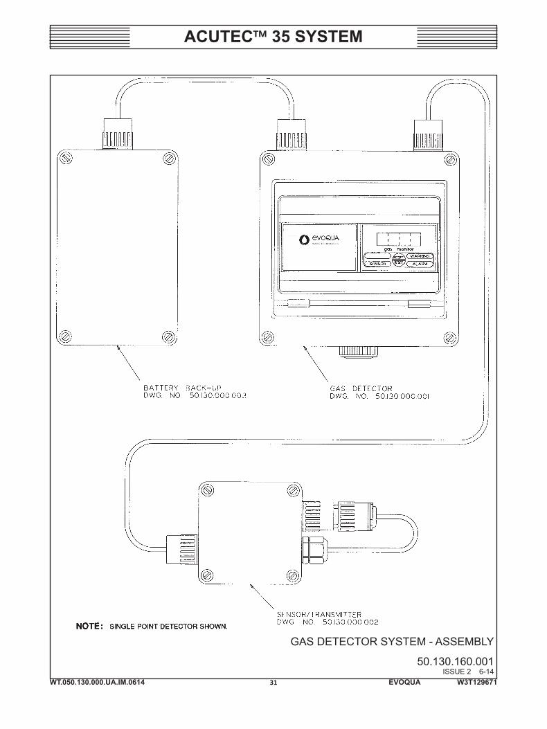
One Receiver Module is connected to each gas Sensor/Transmitter with a two-conductor cable, and provides information on the gas concentration in the sensor area. Receivers are powered by the Power Supply Module supplied with the Gas Detector system.
The Series 50-130 Sensor/Transmitter consists of an electrochemical gas sen-sor and an electronic amplifier that transmits a gas concentration signal to a Receiver Module located in the Control Unit. An optional gas generator may be ordered which enables the Receiver to automatically test the sensor every 24 hours.
NOTE: When ordering material always specify model and serial number of apparatus.
Table Of Contents
Very Important Safety Precautions ................................... SP-1,-2Regional Offices ................................................................ 1.010-1Technical Data ................................................................... Section 1Installation ........................................................................ Section 2Operation ......................................................................... Section 3Service .............................................................................. Section 4Parts Illustrations .............................................................. Section 5Spare Parts List ................................................................. Section 6

EVOQUA W3T129671
ACUTEC™ 35 SYSTEM
WT.050.130.000.UA.IM.0614 SP-1
VERY IMPORTANT SAFETY PRECAUTIONS
This page titled “Very Important Safety Precautions” provides, in brief, information of urgent importance rela-tive to safety in the installation, operation, and maintenance of this equipment.
WARNING
TO AVOID POSSIBLE SEVERE PERSONAL INJURY AND EQUIPMENT DAMAGE, OBSERVE THE FOLLOWING PRE-CAUTIONS:
GASES DETECTED ARE HAZARDOUS SUBSTANCES, AND IF BREATHED IN HIGH CONCENTRATIONS CAN CAUSE DEATH. THE OPERATION OF THIS DETECTOR MUST BE CHECKED AND VERIFIED FREQUENTLY ON A REGULAR SCHEDULE.
TO AVOID INJURY FROM ELECTRICAL SHOCK, TURN POWER SOURCES OFF BEFORE SERVICING EQUIPMENT.
TO AVOID POSSIBLE SEVERE PERSONAL INJURY OR DAMAGE TO EQUIPMENT, THIS PRODUCT SHOULD ONLY BE USED WITH POWER SUPPLIES THAT HAVE A SINGLE HOT WIRE WITH RESPECT TO EARTH. THE WIRE CONNECTED TO POWER SUPPLY TERMINAL “N” MUST BE NEUTRAL. POWER AND EARTH GROUND MUST BE PROPERLY CON-NECTED AS SHOWN.
THE GENERAL SENSOR RESPONSE TEST, AS DESCRIBED IN THIS MANUAL, MUST BE PERFORMED WHENEVER A NEW SENSOR IS INSTALLED.
AFTER ANY MAINTENANCE THE DETECTOR SHOULD BE TESTED FOR RESPONSE TO ASSURE NORMAL OPERATION.
REPLACE SENSOR IMMEDIATELY IF SENSOR FAILS GAS TEST.
HANDLE BATTERIES WITH CARE, BEING CERTAIN NOT TO SHORT TERMINALS, AS SEVERE ARCING OR EXPLOSION COULD OCCUR.
TO ENSURE PROPER AND SAFE OPERATION OF THIS EQUIPMENT, USE ONLY EVOQUA WATER TECHNOLOGIES LISTED PARTS EXCEPT COMMERCIALLY AVAILABLE PARTS AS IDENTIFIED BY COMPLETE DESCRIPTION ON PARTS LIST. THE USE OF UNLISTED PARTS CAN RESULT IN EQUIPMENT MALFUNCTIONS CAUSING POSSIBLE SEVERE PERSONAL INJURY.
THIS EQUIPMENT SHOULD BE INSTALLED, OPERATED AND SERVICED ONLY BY TRAINED, QUALIFIED PERSONNEL WHO ARE THOROUGHLY FAMILIAR WITH THE ENTIRE CONTENTS OF THIS INSTRUCTION BOOK.

EVOQUA W3T129671
ACUTEC™ 35 SYSTEM
WT.050.130.000.UA.IM.0614 SP-2
VERY IMPORTANT SAFETY PRECAUTIONS (CONT’D)
DO NOT DISCARD THIS INSTRUCTION BOOK UPON COMPLETION OF INSTALLATION. INFORMATION PROVIDED IS ESSENTIAL TO PROPER AND SAFE OPERATION AND MAINTENANCE. ADDITIONAL OR REPLACEMENT COPIES OF THIS INSTRUCTION BOOK ARE AVAILABLE FROM:
Evoqua Water Technologies725 Wooten RoadColorado Springs, CO 80915Phone: (800) 524-6324
NOTE
Minor part number changes may be incorporated into Evoqua Water Technologies products from time to time that are not immediately reflected in the instruction book. If such a change apparently has been made in your equipment and does not appear to be reflected in your instruction book, contact your local Evoqua Water Technologies sales office for information.
Please include the equipment serial number in all correspondence. It is essential for effective communication and proper equipment identification.
EVOQUA W3T129671WT.050.130.000.UA.IM.0614
ACUTEC™ 35 SYSTEM
REGIONAL OFFICES
INSTALLATION, OPERATION, MAINTENANCE, AND SERVICE INFORMATION
Direct any questions concerning this equipment that are not answered in the instruction book to the Reseller from whom the equipment was purchased. If the equipment was purchased directly from Evoqua Water Tech-nologies, Colorado Springs, CO contact the office indicated below.
UNITED STATES
725 Wooten RoadColorado Springs, CO 80915TEL: (800) 524-6324
CANADA
If the equipment was purchased directly from Evoqua Water Technologies, Canada, contact the nearest office indicated below.
ONTARIO QUEBEC
Evoqua Water Technologies Ltd. Evoqua Technologies des Eaux Itee2045 Drew Road 505 Levy StreetMississauga, Ontario St. Laurent, QuebecL5S 1S4 H4R 2N9(905) 944-2800 (450) 582-4266
1.010-1


WT.050.130.000.UA.IM.0614
ACUTEC™ 35 SYSTEM
1 EVOQUA W3T129671
SECTION 1 – TECHNICAL DATA
List Of Contents
PARA./DWG. NO.
Technical Data ................................................................... 1.1Interferences .................................................................... 1.2
WT.050.130.000.UA.IM.0614
ACUTEC™ 35 SYSTEM
2 EVOQUA W3T129671
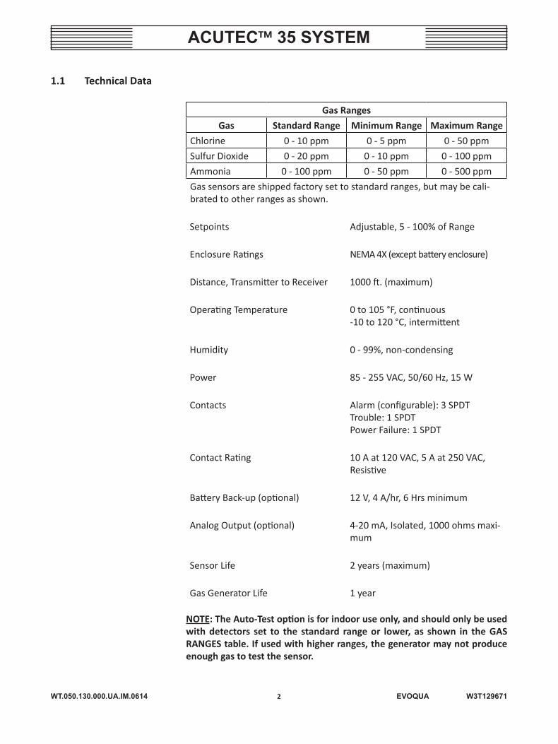
1.1 Technical Data
Gas Ranges
Gas Standard Range Minimum Range Maximum Range
Chlorine 0 - 10 ppm 0 - 5 ppm 0 - 50 ppm
Sulfur Dioxide 0 - 20 ppm 0 - 10 ppm 0 - 100 ppm
Ammonia 0 - 100 ppm 0 - 50 ppm 0 - 500 ppm
Gas sensors are shipped factory set to standard ranges, but may be cali-brated to other ranges as shown.
Setpoints Adjustable, 5 - 100% of Range
Enclosure Ratings NEMA 4X (except battery enclosure)
Distance, Transmitter to Receiver 1000 ft. (maximum)
Operating Temperature 0 to 105 °F, continuous-10 to 120 °C, intermittent
Humidity 0 - 99%, non-condensing
Power 85 - 255 VAC, 50/60 Hz, 15 W
Contacts Alarm (configurable): 3 SPDTTrouble: 1 SPDTPower Failure: 1 SPDT
Contact Rating 10 A at 120 VAC, 5 A at 250 VAC, Resistive
Battery Back-up (optional) 12 V, 4 A/hr, 6 Hrs minimum
Analog Output (optional) 4-20 mA, Isolated, 1000 ohms maxi-mum
Sensor Life 2 years (maximum)
Gas Generator Life 1 year
NOTE: The Auto-Test option is for indoor use only, and should only be used with detectors set to the standard range or lower, as shown in the GAS RANGES table. If used with higher ranges, the generator may not produce enough gas to test the sensor.
WT.050.130.000.UA.IM.0614
ACUTEC™ 35 SYSTEM
3 EVOQUA W3T129671
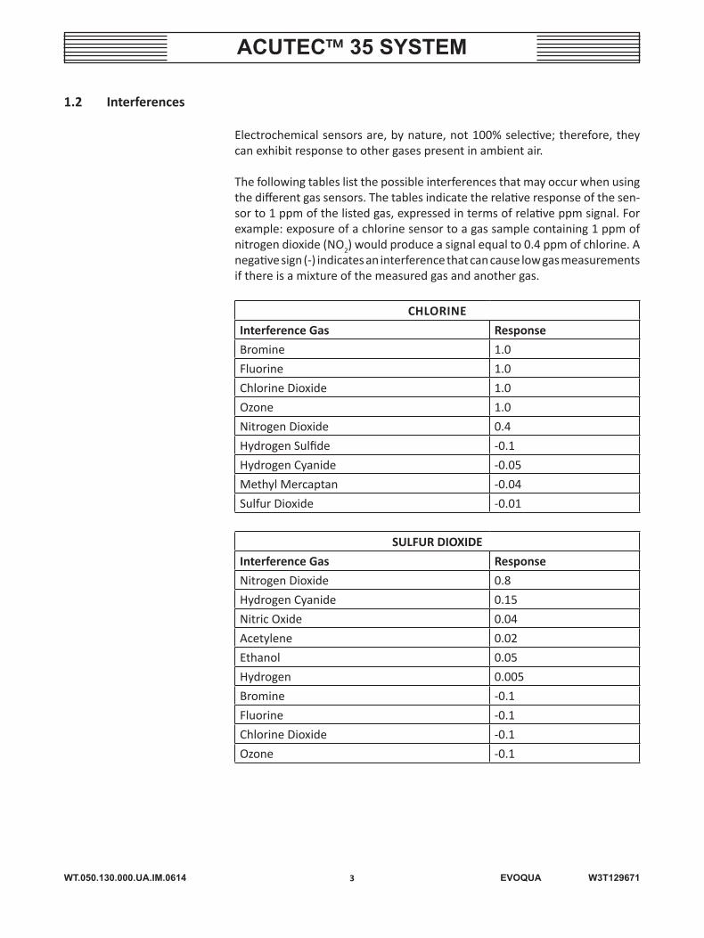
1.2 Interferences
Electrochemical sensors are, by nature, not 100% selective; therefore, they can exhibit response to other gases present in ambient air.
The following tables list the possible interferences that may occur when using the different gas sensors. The tables indicate the relative response of the sen-sor to 1 ppm of the listed gas, expressed in terms of relative ppm signal. For example: exposure of a chlorine sensor to a gas sample containing 1 ppm of nitrogen dioxide (NO2) would produce a signal equal to 0.4 ppm of chlorine. A negative sign (-) indicates an interference that can cause low gas measurements if there is a mixture of the measured gas and another gas.
CHLORINE
Interference Gas Response
Bromine 1.0
Fluorine 1.0
Chlorine Dioxide 1.0
Ozone 1.0
Nitrogen Dioxide 0.4
Hydrogen Sulfide -0.1
Hydrogen Cyanide -0.05
Methyl Mercaptan -0.04
Sulfur Dioxide -0.01
SULFUR DIOXIDE
Interference Gas Response
Nitrogen Dioxide 0.8
Hydrogen Cyanide 0.15
Nitric Oxide 0.04
Acetylene 0.02
Ethanol 0.05
Hydrogen 0.005
Bromine -0.1
Fluorine -0.1
Chlorine Dioxide -0.1
Ozone -0.1
WT.050.130.000.UA.IM.0614
ACUTEC™ 35 SYSTEM
4 EVOQUA W3T129671
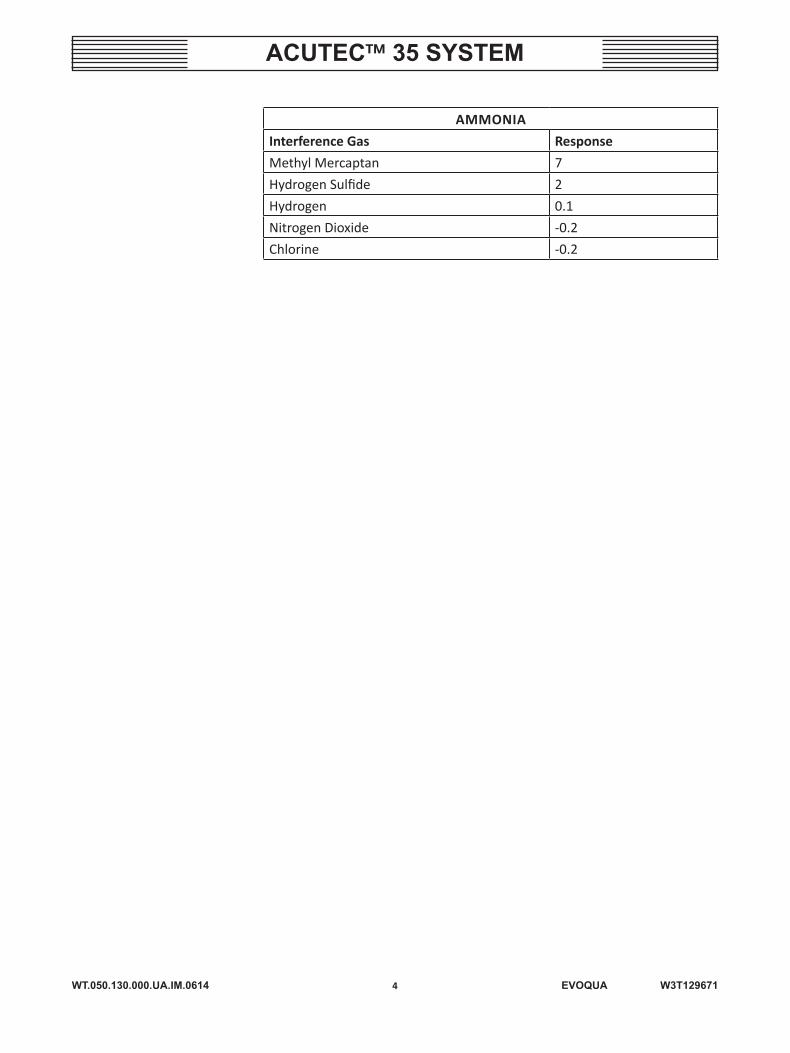
AMMONIA
Interference Gas Response
Methyl Mercaptan 7
Hydrogen Sulfide 2
Hydrogen 0.1
Nitrogen Dioxide -0.2
Chlorine -0.2


WT.050.130.000.UA.IM.0614
ACUTEC™ 35 SYSTEM
5 EVOQUA W3T129671
SECTION 2 – INSTALLATION
List Of Contents
PARA./DWG. NO.
Overview .......................................................................... 2.1General Installation .......................................................... 2.2Mounting Power Supply and Receiver Modules ............... 2.3Electrical Connections ...................................................... 2.4Installation of Power Supply Module................................ 2.5Illustrations Dimensions Single Point Detection System ....................................... 50.130.100.001 Dual Point Detection System ......................................... 50.130.100.002 Sensor/Transmitter ........................................................ 50.130.100.003 Battery Back-up ............................................................. 50.130.100.004 Installation Wiring Single Point Detection System ................................... 50.130.130.001 Dual Point Detection System ...................................... 50.130.130.002
WT.050.130.000.UA.IM.0614
ACUTEC™ 35 SYSTEM
6 EVOQUA W3T129671
2.1 Overview
The Series 50-130 Gas Detection System consists of modular components that can be used in a variety of configurations to fit specific application requirements. Following is a brief description of the major system com-ponents. More detailed information follows later in this manual.
• BASE UNIT: Includes a Power Supply Module housed in a NEMA 4X enclo-sure. Single-Point Units accepts one Receiver Module, and Dual-Point Units accept two Receiver Modules. All units are provided with an audible horn.
• POWER SUPPLY MODULE: Provides power for one or two Receiver Mod-ules, for the audible horn, and for charging an external Battery Back-up. The power supply accepts 85 to 255 volts, ac (50/60 Hz) and mounts on a DIN rail.
• DETECTOR RECEIVER MODULE: Receives a signal from a one Sensor/Trans-mitter, can be set for two alarm levels and provides three alarm contacts. The Receiver Module mounts on a standard DIN rail. Receiver Modules include a Reset/Acknowledge button, provide power for Sensor/Transmit-ters, and control Autotest Generators.
• MONITOR RECEIVER MODULE: Same as the Detector Module, but also includes a digital display of gas level and a 4-20 mA output.
• SENSOR/TRANSMITTER: Consists of an electrochemical gas sensor con-nected to a NEMA 4X transmitter, which sends a signal to a Receiver Module.
• AUTOTEST GENERATOR: An electrochemical gas generator which attaches to Sensor/Transmitters and automatically tests sensor response daily.
NOTE: The Auto-Test option is for indoor use only, and should only be used with detectors set to the standard range or lower, as shown in Section 1.1 – Technical Data. If used with higher ranges, the generator may not produce enough gas to test the sensor.
• BATTERY BACK-UP: The Battery Back-up option for gas detection systems consists of a separate wall-mounted enclosure which houses a battery and a control circuit board. The battery is a sealed, lead-acid type and is rated four ampere-hours.
WT.050.130.000.UA.IM.0614
ACUTEC™ 35 SYSTEM
7 EVOQUA W3T129671
2.2 General Installation
NOTE: Power supply or Receiver modules may be shipped with protective transparent plastic covers. These covers should be peeled off and discarded.
System enclosures, Battery Back-up units, and Sensor/Transmitters are all de-signed for surface mounting using screws or bolts inserted through the recessed mounting holes at each corner of the enclosures. Mounting hole dimensions are shown on the appropriate diagram. Included with each system enclosure are mounting hole templates which can be used to mark hole centers on walls or mounting panels. Mounting recesses are suitable for #8 machine screws or wood screws.
Refer to paragraph 3.4.1, Sensor Installation, for specific information on locat-ing gas sensors.
Enclosures are supplied with conduit hubs and seal rings for water-tight connec-tion of 1/2” NPT threaded conduit. Plastic cable glands may also be purchased to connect cables without conduit.
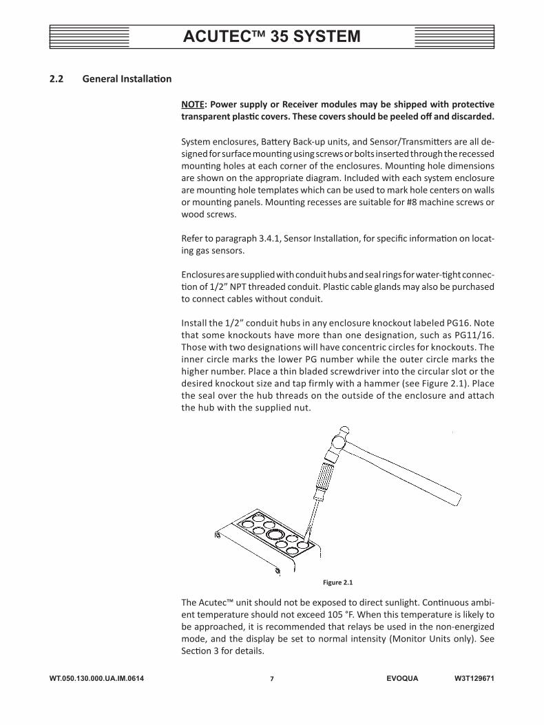
Install the 1/2” conduit hubs in any enclosure knockout labeled PG16. Note that some knockouts have more than one designation, such as PG11/16. Those with two designations will have concentric circles for knockouts. The inner circle marks the lower PG number while the outer circle marks the higher number. Place a thin bladed screwdriver into the circular slot or the desired knockout size and tap firmly with a hammer (see Figure 2.1). Place the seal over the hub threads on the outside of the enclosure and attach the hub with the supplied nut.
Figure 2.1
The Acutec™ unit should not be exposed to direct sunlight. Continuous ambi-ent temperature should not exceed 105 °F. When this temperature is likely to be approached, it is recommended that relays be used in the non-energized mode, and the display be set to normal intensity (Monitor Units only). See Section 3 for details.
WT.050.130.000.UA.IM.0614
ACUTEC™ 35 SYSTEM
8 EVOQUA W3T129671
2.3 Mounting Power Supply and Receiver Modules (See Dwg. 50.130.000.001)
Power Supply and Receiver Modules are mounted to a standard 35 x 7.5 mm DIN rail in the detection system enclosure. The spring loaded clip with the loop holds the module to the rail. To install modules, first slide the bottom of the module under the rail. Then pull the loop out with a small screwdriver while lowering the top of the module onto the rail. To remove modules, reverse this procedure.
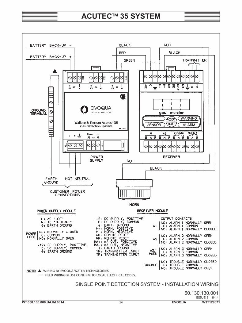
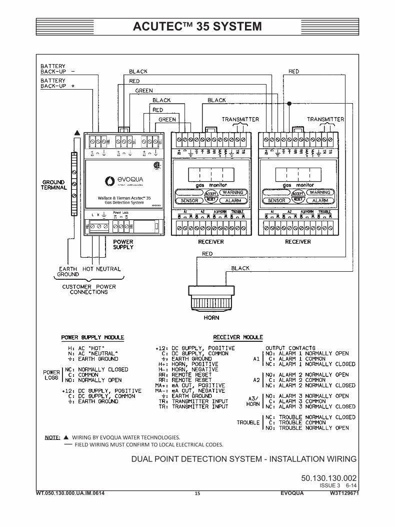
2.4 Electrical Connections (See Dwgs. 50.130.130.001 And 50.130.130.002)
Field wiring required for the Detection System includes connection of ac power, connection of two-conductor cable between the Receiver and the Sensor/Transmitter, connection of the Battery Back-up unit (when purchased), and connection of the audible horn to Receiver Modules. A 25-foot length of two-conductor cable is supplied for each Sensor/Transmitter. Longer lengths of up to 1000 feet may be used when required.
The ac input power is connected to the lower left of the Power Module, as shown in the Installation Wiring drawings. A ground terminal is provided on the mounting track for connection of earth ground. For safe operation and to avoid noise interference, it is important that earth ground be connected to this terminal first, and then to the power input earth ground terminal on the Power Supply Module, as shown.
WARNING: TO AVOID POSSIBLE SEVERE PERSONAL INJURY OR DAMAGE TO EQUIPMENT, THIS PRODUCT SHOULD ONLY BE USED WITH POWER SUPPLIES THAT HAVE A SINGLE HOT WIRE WITH RESPECT TO EARTH. THE WIRE CONNECTED TO POWER SUPPLY TERMINAL “N” MUST BE NEUTRAL. POWER AND EARTH GROUND MUST BE PROPERLY CONNECTED AS SHOWN.
NOTE: Field wiring must conform to local electrical codes.
The wiring drawings show internal wiring of the systems. Sensor/Transmitter connections are shown in paragraph 3.4.1, Sensor Installation.
All terminal blocks are plug-in type, and can be unplugged allowing replace-ment of modules without removing individual wires.
Electrical connection is made between the Battery Back-up unit and the Power Supply Module. The circuit board mounted on the battery contains a two-position plug-in terminal block marked plus and minus. The plus terminal is connected to terminal B+ of the power supply and the minus terminal is connected to B- of the power supply.
!
WT.050.130.000.UA.IM.0614
ACUTEC™ 35 SYSTEM
9 EVOQUA W3T129671
2.5 Installation of Power Supply Module
The Power Supply Module used in the gas detection system operates on ac supplies of 85 volts to 255 volts, at 50/60 Hz. No adjustments or modifications are required of the user.
WT.050.130.000.UA.IM.0614
ACUTEC™ 35 SYSTEM
10 EVOQUA W3T129671
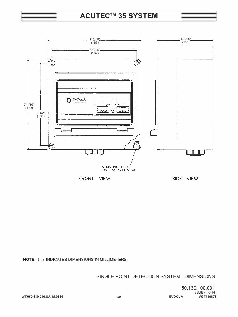
NOTE: ( ) INDICATES DIMENSIONS IN MILLIMETERS.
SINGLE POINT DETECTION SYSTEM - DIMENSIONS
50.130.100.001ISSUE 4 6-14
7-3/16”(183)
6-9/16”(167)
4-5/16”(110)
7-1/16”(179)
6-1/2”(165)
WT.050.130.000.UA.IM.0614
ACUTEC™ 35 SYSTEM
11 EVOQUA W3T129671
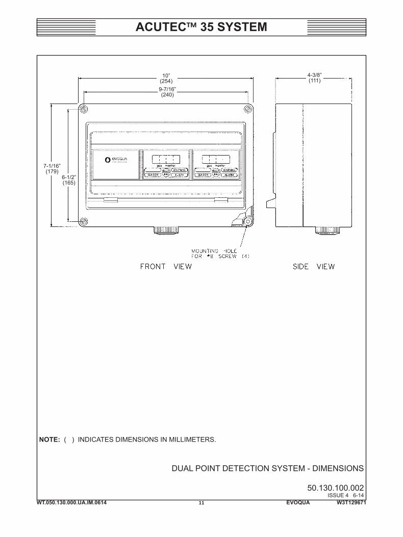
NOTE: ( ) INDICATES DIMENSIONS IN MILLIMETERS.
DUAL POINT DETECTION SYSTEM - DIMENSIONS
50.130.100.002ISSUE 4 6-14
9-7/16”(240)
10”(254)
4-3/8”(111)
7-1/16”(179)
6-1/2”(165)
WT.050.130.000.UA.IM.0614
ACUTEC™ 35 SYSTEM
12 EVOQUA W3T129671
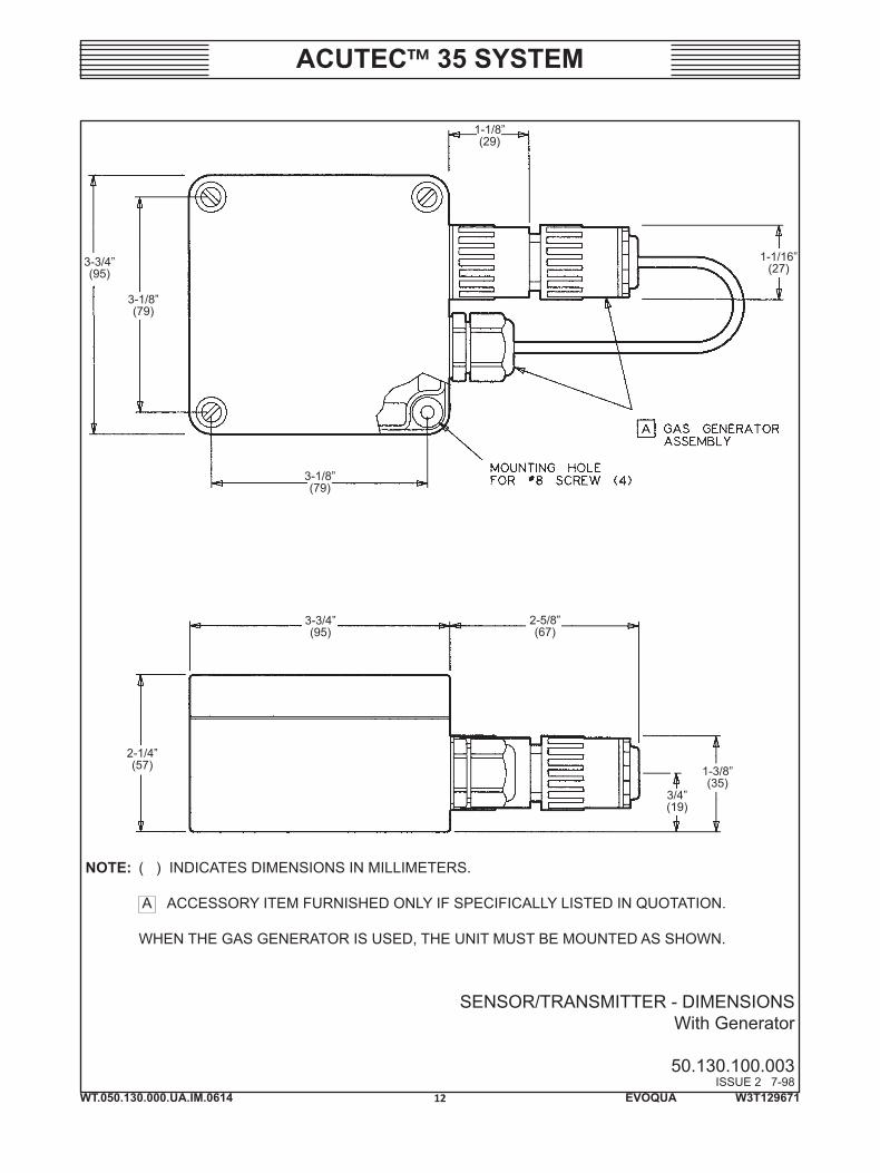
NOTE: ( ) INDICATES DIMENSIONS IN MILLIMETERS.
A ACCESSORY ITEM FURNISHED ONLY IF SPECIFICALLY LISTED IN QUOTATION.
WHEN THE GAS GENERATOR IS USED, THE UNIT MUST BE MOUNTED AS SHOWN.
SENSOR/TRANSMITTER - DIMENSIONSWith Generator
50.130.100.003ISSUE 2 7-98
3-3/4”(95)
3-1/8”(79)
3-3/4”(95)
1-1/8”(29)
1-1/16”(27)
3-1/8”(79)
2-5/8”(67)
1-3/8”(35)
3/4”(19)
2-1/4”(57)
WT.050.130.000.UA.IM.0614
ACUTEC™ 35 SYSTEM
13 EVOQUA W3T129671
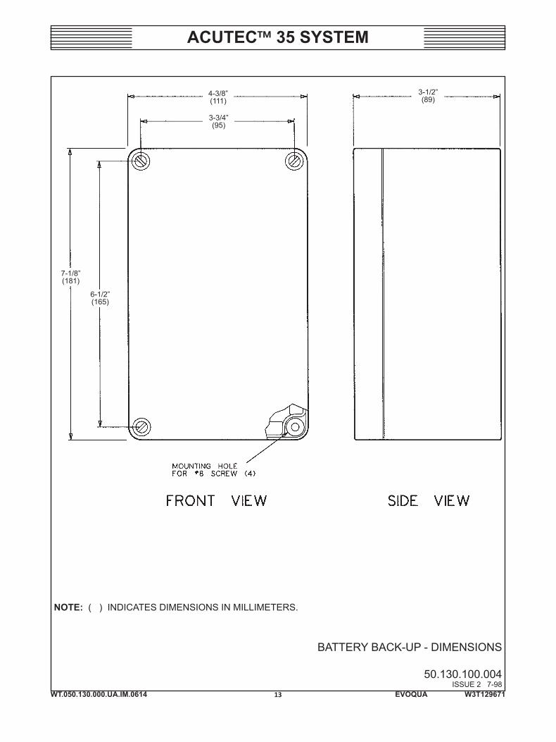
NOTE: ( ) INDICATES DIMENSIONS IN MILLIMETERS.
BATTERY BACK-UP - DIMENSIONS
50.130.100.004ISSUE 2 7-98
4-3/8”(111)
3-3/4”(95)
3-1/2”(89)
7-1/8”(181)
6-1/2”(165)
WT.050.130.000.UA.IM.0614
ACUTEC™ 35 SYSTEM
14 EVOQUA W3T129671
SINGLE POINT DETECTION SYSTEM - INSTALLATION WIRING
50.130.130.001ISSUE 3 6-14
NOTE: WIRING BY EVOQUA WATER TECHNOLOGIES. FIELD WIRING MUST CONFIRM TO LOCAL ELECTRICAL CODES.
WT.050.130.000.UA.IM.0614
ACUTEC™ 35 SYSTEM
15 EVOQUA W3T129671
DUAL POINT DETECTION SYSTEM - INSTALLATION WIRING
50.130.130.002ISSUE 3 6-14
NOTE: WIRING BY EVOQUA WATER TECHNOLOGIES. FIELD WIRING MUST CONFIRM TO LOCAL ELECTRICAL CODES.

WT.050.130.000.UA.IM.0614
ACUTEC™ 35 SYSTEM
16 EVOQUA W3T129671

WT.050.130.000.UA.IM.0614
ACUTEC™ 35 SYSTEM
17 EVOQUA W3T129671
SECTION 3 – OPERATION
List Of Contents
PARA./DWG. NO.
Power Supply Operation ................................................... 3.1Receiver Module Operation ............................................. 3.2 Configuration Switches .................................................. 3.2.1 Range Selection ............................................................. 3.2.2 Setpoint Selection ......................................................... 3.2.3 Relay Configuration ....................................................... 3.2.4 Alarm Delay ................................................................... 3.2.5 Display Intensity ............................................................ 3.2.6 Auto-Test Enable ........................................................... 3.2.7Receiver Module Startup .................................................. 3.3 Alarm Acknowledge and Reset ...................................... 3.3.1 Sensor Trouble Alarm and Relays .................................. 3.3.2 Auto-Test Function ........................................................ 3.3.3 Lamp and Horn Test ...................................................... 3.3.4 Relay Inhibit ................................................................... 3.3.5 Manual Auto-Test .......................................................... 3.3.6 Remote Reset ................................................................ 3.3.7 Analog Output ............................................................... 3.3.8Sensor Transmitter Operation .......................................... 3.4 Sensor Installation ......................................................... 3.4.1 Sensor Location (Chlorine, Sulfur Dioxide, and Ammonia) ........................................................... 3.4.2Battery Back-Up Operation ............................................... 3.5Illustrations Assembly – Gas Detector System .................................. 50.130.160.001
WT.050.130.000.UA.IM.0614
ACUTEC™ 35 SYSTEM
18 EVOQUA W3T129671
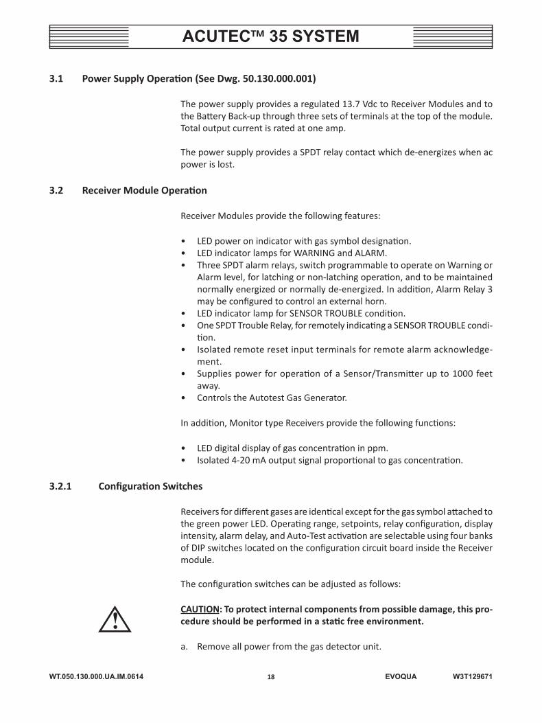
3.1 Power Supply Operation (See Dwg. 50.130.000.001)
The power supply provides a regulated 13.7 Vdc to Receiver Modules and to the Battery Back-up through three sets of terminals at the top of the module. Total output current is rated at one amp.
The power supply provides a SPDT relay contact which de-energizes when ac power is lost.
3.2 Receiver Module Operation
Receiver Modules provide the following features:
• LED power on indicator with gas symbol designation.• LED indicator lamps for WARNING and ALARM.• Three SPDT alarm relays, switch programmable to operate on Warning or
Alarm level, for latching or non-latching operation, and to be maintained normally energized or normally de-energized. In addition, Alarm Relay 3 may be configured to control an external horn.
• LED indicator lamp for SENSOR TROUBLE condition.• One SPDT Trouble Relay, for remotely indicating a SENSOR TROUBLE condi-
tion.• Isolated remote reset input terminals for remote alarm acknowledge-
ment.• Supplies power for operation of a Sensor/Transmitter up to 1000 feet
away.• Controls the Autotest Gas Generator.
In addition, Monitor type Receivers provide the following functions:
• LED digital display of gas concentration in ppm.• Isolated 4-20 mA output signal proportional to gas concentration.
3.2.1 Configuration Switches
Receivers for different gases are identical except for the gas symbol attached to the green power LED. Operating range, setpoints, relay configuration, display intensity, alarm delay, and Auto-Test activation are selectable using four banks of DIP switches located on the configuration circuit board inside the Receiver module.
The configuration switches can be adjusted as follows:
CAUTION: To protect internal components from possible damage, this pro-cedure should be performed in a static free environment.
a. Remove all power from the gas detector unit.
!
WT.050.130.000.UA.IM.0614
ACUTEC™ 35 SYSTEM
19 EVOQUA W3T129671
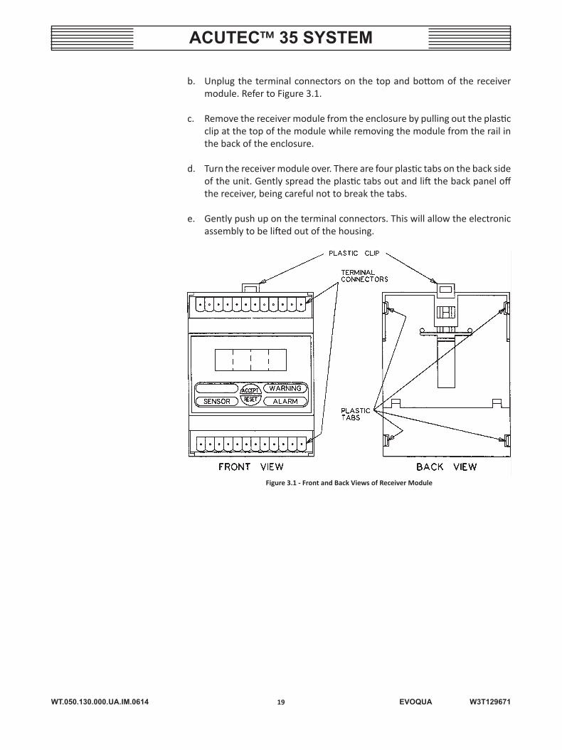
b. Unplug the terminal connectors on the top and bottom of the receiver module. Refer to Figure 3.1.
c. Remove the receiver module from the enclosure by pulling out the plastic clip at the top of the module while removing the module from the rail in the back of the enclosure.
d. Turn the receiver module over. There are four plastic tabs on the back side of the unit. Gently spread the plastic tabs out and lift the back panel off the receiver, being careful not to break the tabs.
e. Gently push up on the terminal connectors. This will allow the electronic assembly to be lifted out of the housing.
Figure 3.1 - Front and Back Views of Receiver Module
WT.050.130.000.UA.IM.0614
ACUTEC™ 35 SYSTEM
20 EVOQUA W3T129671
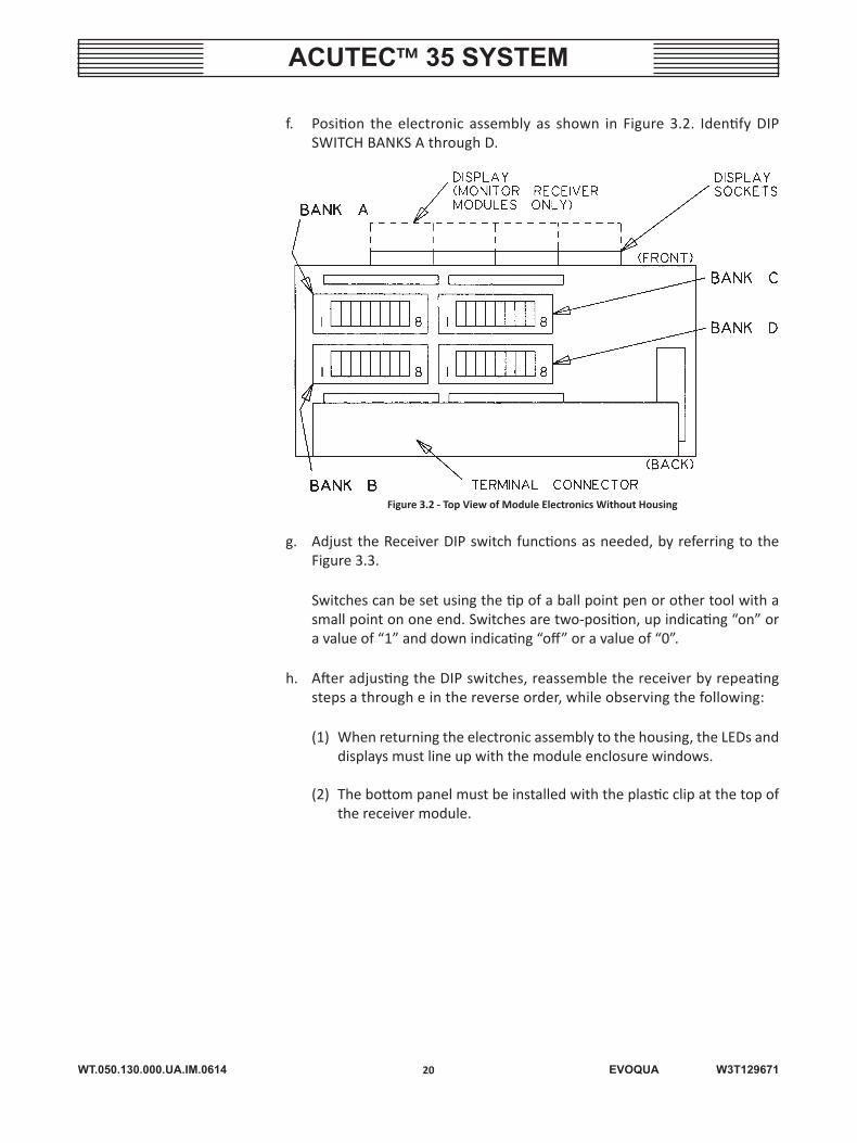
f. Position the electronic assembly as shown in Figure 3.2. Identify DIP SWITCH BANKS A through D.
Figure 3.2 - Top View of Module Electronics Without Housing
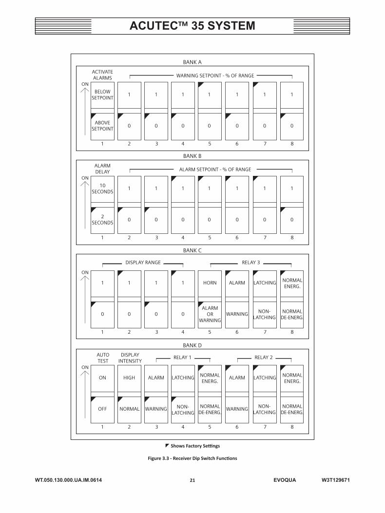
g. Adjust the Receiver DIP switch functions as needed, by referring to the Figure 3.3.
Switches can be set using the tip of a ball point pen or other tool with a small point on one end. Switches are two-position, up indicating “on” or a value of “1” and down indicating “off” or a value of “0”.
h. After adjusting the DIP switches, reassemble the receiver by repeating steps a through e in the reverse order, while observing the following:
(1) When returning the electronic assembly to the housing, the LEDs and displays must line up with the module enclosure windows.
(2) The bottom panel must be installed with the plastic clip at the top of the receiver module.
WT.050.130.000.UA.IM.0614
ACUTEC™ 35 SYSTEM
21 EVOQUA W3T129671
BELOW SETPOINT
ACTIVATEALARMS WARNING SETPOINT - % OF RANGE
BANK A
ABOVESETPOINT
1 2
1
ON
1 1 1 1 1 1
0 0 0 0 0 0 0
3 4 5 6 7 8
10SECONDS
ALARM DELAY ALARM SETPOINT - % OF RANGE
BANK B
2SECONDS
1 2
1
ON
1 1 1 1 1 1
0 0 0 0 0 0 0
3 4 5 6 7 8
DISPLAY RANGE
BANK C
1 2
1
ON
1 1 HORN1 ALARM LATCHING NORMALENERG.
00 0 0ALARM
ORWARNING
WARNING NON-LATCHING
NORMALDE-ENERG.
3 4 5 6 7 8
RELAY 3
BANK D
1 2
HIGH
ON
ALARM LATCHINGON ALARM LATCHING NORMALENERG.
NORMALENERG.
NORMALOFF WARNING NON-LATCHING
WARNING NON-LATCHING
NORMALDE-ENERG.
NORMALDE-ENERG.
3 4 5 6 7 8
RELAY 2RELAY 1DISPLAYINTENSITY
AUTOTEST
Shows Factory Settings
Figure 3.3 - Receiver Dip Switch Functions
WT.050.130.000.UA.IM.0614
ACUTEC™ 35 SYSTEM
22 EVOQUA W3T129671
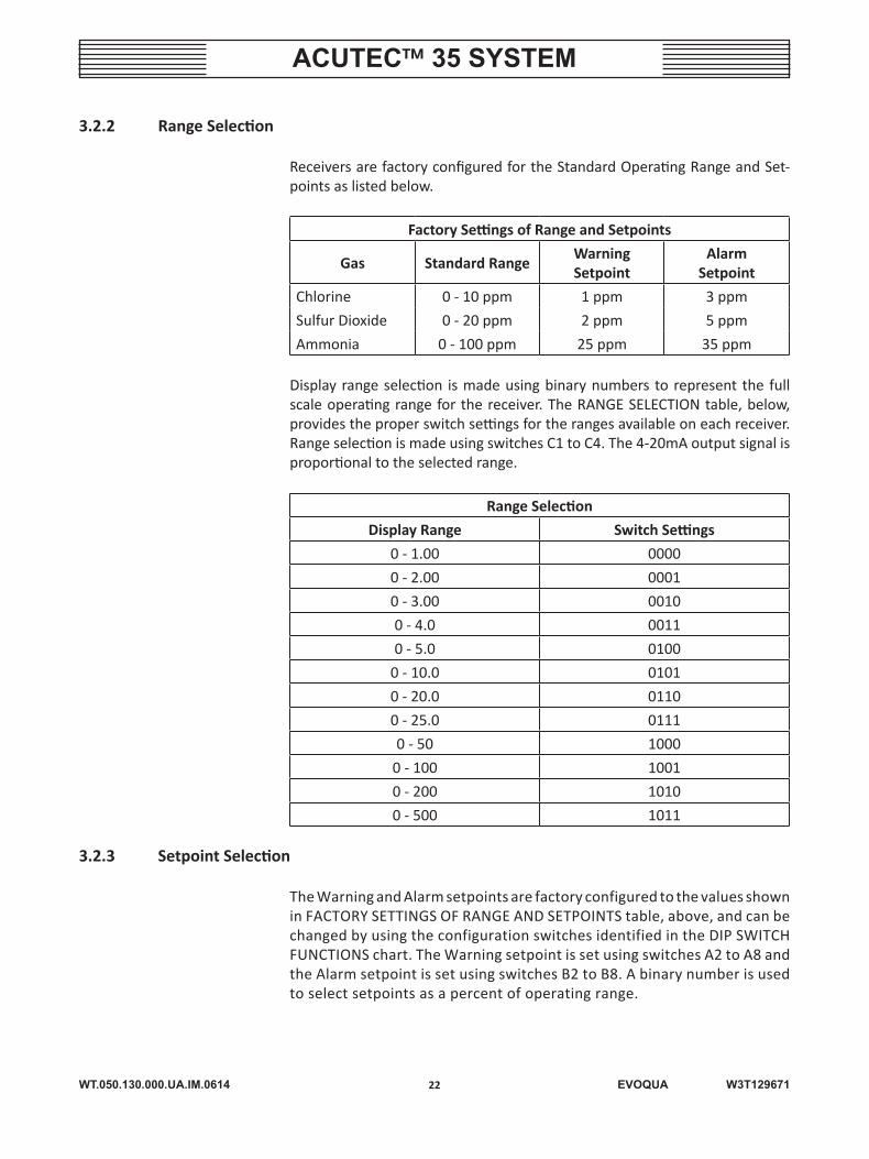
3.2.2 Range Selection
Receivers are factory configured for the Standard Operating Range and Set-points as listed below.
Factory Settings of Range and Setpoints
Gas Standard RangeWarningSetpoint
AlarmSetpoint
Chlorine 0 - 10 ppm 1 ppm 3 ppm
Sulfur Dioxide 0 - 20 ppm 2 ppm 5 ppm
Ammonia 0 - 100 ppm 25 ppm 35 ppm
Display range selection is made using binary numbers to represent the full scale operating range for the receiver. The RANGE SELECTION table, below, provides the proper switch settings for the ranges available on each receiver. Range selection is made using switches C1 to C4. The 4-20mA output signal is proportional to the selected range.
Range Selection
Display Range Switch Settings
0 - 1.00 0000
0 - 2.00 0001
0 - 3.00 0010
0 - 4.0 0011
0 - 5.0 0100
0 - 10.0 0101
0 - 20.0 0110
0 - 25.0 0111
0 - 50 1000
0 - 100 1001
0 - 200 1010
0 - 500 1011
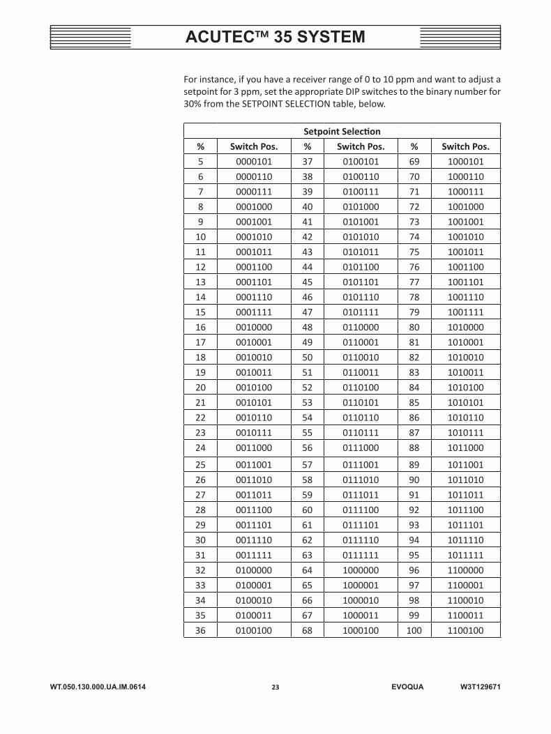
3.2.3 Setpoint Selection
The Warning and Alarm setpoints are factory configured to the values shown in FACTORY SETTINGS OF RANGE AND SETPOINTS table, above, and can be changed by using the configuration switches identified in the DIP SWITCH FUNCTIONS chart. The Warning setpoint is set using switches A2 to A8 and the Alarm setpoint is set using switches B2 to B8. A binary number is used to select setpoints as a percent of operating range.
WT.050.130.000.UA.IM.0614
ACUTEC™ 35 SYSTEM
23 EVOQUA W3T129671
For instance, if you have a receiver range of 0 to 10 ppm and want to adjust a setpoint for 3 ppm, set the appropriate DIP switches to the binary number for 30% from the SETPOINT SELECTION table, below.
Setpoint Selection
% Switch Pos. % Switch Pos. % Switch Pos.
5 0000101 37 0100101 69 1000101
6 0000110 38 0100110 70 1000110
7 0000111 39 0100111 71 1000111
8 0001000 40 0101000 72 1001000
9 0001001 41 0101001 73 1001001
10 0001010 42 0101010 74 1001010
11 0001011 43 0101011 75 1001011
12 0001100 44 0101100 76 1001100
13 0001101 45 0101101 77 1001101
14 0001110 46 0101110 78 1001110
15 0001111 47 0101111 79 1001111
16 0010000 48 0110000 80 1010000
17 0010001 49 0110001 81 1010001
18 0010010 50 0110010 82 1010010
19 0010011 51 0110011 83 1010011
20 0010100 52 0110100 84 1010100
21 0010101 53 0110101 85 1010101
22 0010110 54 0110110 86 1010110
23 0010111 55 0110111 87 1010111
24 0011000 56 0111000 88 1011000
25 0011001 57 0111001 89 1011001
26 0011010 58 0111010 90 1011010
27 0011011 59 0111011 91 1011011
28 0011100 60 0111100 92 1011100
29 0011101 61 0111101 93 1011101
30 0011110 62 0111110 94 1011110
31 0011111 63 0111111 95 1011111
32 0100000 64 1000000 96 1100000
33 0100001 65 1000001 97 1100001
34 0100010 66 1000010 98 1100010
35 0100011 67 1000011 99 1100011
36 0100100 68 1000100 100 1100100
WT.050.130.000.UA.IM.0614
ACUTEC™ 35 SYSTEM
24 EVOQUA W3T129671
The Gas Detector is factory set to alarm when gas concentrations above the chosen setpoints are exceeded; however, if switch A1 is set to the ON position, alarms will be initiated when gas concentration is below the setpoint.
3.2.4 Relay Configuration
• FACTORY CONFIGURATION OF RELAYS —
* Relay 1 – Configured to trip above the Warning setpoint and set for normally energized, non-latching operation.
* Relay 2 – Configured to trip above the Alarm setpoint and set for nor-mally energized, latching operation.
* Relay 3 – Configured to trip above the Alarm setpoint and set for nor-mally energized, latching operation, not for horn operation.
* Alarm Delay – Configured for two-second delay.
• WARNING OR ALARM — Each relay can be assigned to either the Warning or Alarm setpoint. As shown in the DIP SWITCH FUNCTIONS chart, switches D3, D6, and C6 configure each relay. When Warning is selected, the relay will activate when the Warning lamp on the front panel lights. When Alarm is selected, the relay will activate with the Alarm lamp on the front panel.
• NORMALLY ENERGIZED/DE-ENERGIZED — Relays one through three are factory set to the normally energized mode, providing “Fail-Safe” opera-tion. This means the relays are energized in a normal condition and will de-energize for a Warning or Alarm condition, or if power is lost to the system. However, operation in this mode will reduce the period of operation on Battery Back-up. The relays may be set to the normally de-energized mode by setting switches C8, D5, and D8 to the off position. To avoid bat-tery drain and internal heat generation, unused relays should be set to Normally De-Energized.
• LATCHING OR NON-LATCHING — Relays may be either Latching or Non-latching. A latching relay activates when gas concentration exceeds the setpoint, but will only de-activate when the push-button on the front of the receiver is pressed after the gas concentration has fallen below the setpoint. A non-latching relay will automatically de-activate when the gas concentration falls below the setpoint. Selection of the latch/non-latch function uses switches D4, D7, and C7.
• EXTERNAL HORN RELAY — Relay 3 provides an additional configuration op-tion not available on relays 1 or 2. Switch C5 allows Relay 3 to be configured for use in activating an external audible horn. When switch C5 is on, any external horn tied to Relay 3 will sound intermittently when the warning setpoint is exceeded and will go to steady-on when the alarm setpoint is exceeded. The relay will de-activate when the push-button switch is pressed or when the remote reset terminals are connected, silencing the external horn.
WT.050.130.000.UA.IM.0614
ACUTEC™ 35 SYSTEM
25 EVOQUA W3T129671
3.2.5 Alarm Delay
A time delay precedes the activation of alarm relays to eliminate false alarms due to electrical transients. The delay is factory set to two seconds, but can be changed to 10 seconds with switch B1. The delay time affects both the alarm indicator lamps and the associated relays.
3.2.6 Display Intensity (Monitor Units Only)
The LED numeric display is factory set in the normal intensity mode, and can be set for high intensity by the user; however, to avoid internal heating, and battery drain, it is recommended that the display remain at normal intensity. Switch D2 is used to select normal or high intensity display mode.
3.2.7 Auto-Test Enable
The receiver module is shipped from the factory with the Auto-Test option disabled. If the Autotest Gas Generator (optional) is installed on the system, the receiver module cover must be removed and the autotest switch (D1) must be moved to the “on” position.
NOTE: The Auto-Test option is for indoor use only, and should only be used with detectors set to the standard range or lower, as listed in Section 1.1 – Technical Data. If used with higher ranges, the generator may not produce enough gas to test the sensor.
3.3 Receiver Module Startup
Receiver front panels contain three LED bars which indicate Warning, Alarm, and Sensor Trouble conditions. A fourth, green bar LED is marked with the type of gas which the receiver operates with. Monitor type receivers have a four digit numeric LED display which indicates gas concentration in ppm.
When power is first applied, all alarm functions will be inhibited for five minutes while the system is allowed to stabilize. This is indicated by Warning and Alarm lamps flashing in an alternating pattern. Monitors will display the Full Scale Range setting for three seconds, then the Warning Setpoint for three seconds, followed by the Alarm Setpoint for three seconds. The display will then indicate the detected gas level, which will appear to be high until the sensor stabilizes.
NOTE: It is strongly recommended that sensors be powered overnight upon initial startup before adjustments are made and before connections are made to alarm relays. Sensors which are powered for the first time may remain in an alarm state beyond the five minute inhibit period and may take several hours to fully stabilize.
WT.050.130.000.UA.IM.0614
ACUTEC™ 35 SYSTEM
26 EVOQUA W3T129671
3.3.1 Alarm Acknowledge and Reset
The front panel of the Receiver contains one push-button, marked Accept/Reset, which is used for a number of different functions. When the Receiver is in normal operation, a gas leak that exceeds the warning setpoint will cause the Warning indicator to flash and the internal horn to sound intermittently. If the alarm setpoint is exceeded, the Alarm indicator will flash and the horn will sound steadily. Pressing the button the first time will silence the audible horn, and will change the Warning and Alarm indicators from flash to steady-on. The Warning indicator will automatically shut off when gas concentration falls below the setpoint, but the Alarm indicator will remain on. Pressing the button after the gas has cleared will reset the Alarm indicator.
Operation of the alarm relays depends on the configuration selected for each one (see paragraph 3.2.1, Configuration Switches).
3.3.2 Sensor Trouble Alarm and Relays
Receivers contain a Trouble Relay which is associated with the Sensor Trouble indicator. A Sensor Trouble Alarm will be activated if the transmitter input is disconnected or shorted or if the Detector fails to pass an auto-test. If these conditions occur, the Sensor Trouble indicator will light, the horn will sound intermittently, and the Trouble Relay will change state. Note that the Trouble Relay is a fail-safe relay. Under normal conditions, the coil of this relay is ener-gized, and it de-energizes when a Sensor Trouble Alarm occurs or if power fails. After the trouble condition clears, press the push-button or close the remote reset contacts to reset the Sensor Trouble Alarm.
3.3.3 Auto-Test Function
NOTE: The Auto-Test option is for indoor use only, and should only be used with detectors set to the standard range or lower, as listed in Section 1.1 – Technical Data. If used with higher ranges, the generator may not produce enough gas to test the sensor.
The optional Auto-Test feature verifies the proper operation of gas detection systems automatically. It is enabled when configuration switch D1 is in the “on” position. Auto-Test uses an electrochemical Gas Generator attached to the gas sensor and controlled from the receiver. Every 24 hours, the microcomputer in the receiver activates the Gas Generator and monitors the output of the gas sensor.
During the time when an Auto-Test is in progress, the alarm relays are inhib-ited. This is indicated by the warning and alarm indicators alternately flashing. Typically, an auto-test will last only a few seconds. After completion of the test the alarm response will be delayed to allow gas to clear from the sensor/generator and for the sensor to recover. The system will be fully inhibited for
WT.050.130.000.UA.IM.0614
ACUTEC™ 35 SYSTEM
27 EVOQUA W3T129671
two minutes, followed by an eight minute period during which the detector will respond only to gas levels of greater than 50% of full scale.
When the Auto-Test is activated, the generator will turn on for a maximum of five minutes. If no sensor response is detected during this time, the generator will turn off and the receiver will wait for 15 minutes before initiating another Auto-Test. If it fails this second test, a Sensor Trouble Alarm will be initiated, as described earlier. The Receiver will auto-test two more times at one hour intervals. If the sensor passes either of these tests, the Sensor Trouble Alarm will reset.
3.3.4 Lamp and Horn Test
When the Receiver is in the normal mode, pressing the push-button and holding it for two seconds will illuminate all digital display segments and LED indicator bars, and will sound the internal horn. Upon releasing the button, the receiver will return to its previous state.
3.3.5 Relay Inhibit
Alarm relays in the Receiver can be inhibited for up to four hours to allow calibration or testing of Sensor/Transmitters without activating external alarm or control devices.
To initiate the inhibit mode, with the Receiver in the normal mode, press and hold the push-button for approximately five seconds. The lamp test will occur first, but continue to hold the button down. Once the lamps have shut off, re-lease the button. The warning and alarm lamps will begin to flash alternately for a few seconds. If the Auto-Test configuration switch is in the “on” position and the push-button is not pressed, the Sensor trouble lamp will flash after the Alarm/Warning lamps have stopped flashing. If no action is taken, the Receiver will return to the normal mode.
If the push-button is pressed and released while the warning and alarm lamps are in alternating flash, the Receiver will go into the relay inhibit mode. The warning and alarm lamps will continue their alternating rapid flash, and the Receiver will remain in inhibit for four hours or until the button is pressed again. During this period, the display will indicate gas concentration, and the 4-20 mA output will be held at the level it was at before inhibit was initiated, but the relays will not activate. Transmitters may be calibrated while the inhibit is on without setting off external alarms.
When the receiver is in inhibit, the display reads the actual signal down to 0 ppm, and will read negative if the sensor is out of calibration. Normally, the microcomputer sets the display to zero when the signal is less than two percent of full scale, to avoid false readings due to drift and environmental conditions. Because relays are inhibited and the display blanking is bypassed, the inhibit mode is convenient for calibrating the Sensor/Transmitter.
WT.050.130.000.UA.IM.0614
ACUTEC™ 35 SYSTEM
28 EVOQUA W3T129671
3.3.6 Manual Auto-Test
Gas detection systems purchased with the optional Autotest Generator may be tested by manual activation of the Generator from the receiver module. This function will operate only if the Auto-Test configuration switch D1 is “on”. To manually start the Auto-Test function, with the Receiver in the normal mode, follow the sequence described in paragraph 3.3.5, Relay Inhibit, but press the push-button when the Sensor trouble lamp is flashing. The horn will sound a quick beep and the green gas indicator will begin to flash, indicating that the generator is running. The system will go through a normal Auto-Test sequence, exactly the same as the sequence used every 24 hours. The display will show increasing gas values as the sensor begins to respond. When the microcomputer identifies a successful test, the horn will sound one beep. The relay inhibit indication will remain on until the sensor has had time to recover.
If the test fails, a Sensor trouble response will be initiated. Pressing the push-button will silence the horn, but the Sensor trouble contact and light will remain latched on, and cannot be reset until after a 10-minute period. The Sensor/Transmitter should be checked. Either the Sensor or Generator has failed, or something is physically blocking the path between the two. Methods for testing individual gas sensors can be found in Section 4 – Service.
3.3.7 Remote Reset
Receivers are provided with input terminals for connection of a remote reset switch. The remote reset input provides horn silence and alarm reset functions using a switch located at any remote point. When receivers are located at sites with telemetry equipment, the remote reset input may be connected to a relay contact in the telemetry system.
The remote reset input accomplishes the same acknowledge and reset func-tions as the push-button on the front panel. When a switch closure is detected across the remote reset terminals, the detector horn will silence and any latching relays will reset, provided that the gas condition has cleared. The remote reset input will not activate any of the testing or inhibit functions of the receiver.
3.3.8 Analog Output
Monitor Receivers provide an isolated 4-20 mA output signal for interface with recorders, data loggers, or computer systems. The span of the 4-20 mA signal is the same as the range of the receiver selected during the receiver configura-tion. The output will drive loads of 0 to 1000 ohms.
WT.050.130.000.UA.IM.0614
ACUTEC™ 35 SYSTEM
29 EVOQUA W3T129671
3.4 Sensor/Transmitter Operation
Gas sensors are attached directly to transmitter boxes with a water-tight seal. A short sensor cable plugs into the transmitter circuit board. The optional Gas Generator is attached to the sensor and connects to a terminal block on the circuit board.
The Receiver provides power to the Sensor/Transmitter through a two-conductor cable, which is also used to transmit the signal back to the Receiver. The Sen-sor/Transmitter may not be used with a separate power source.
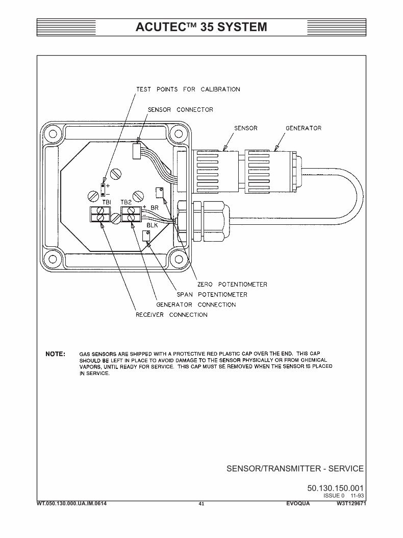
3.4.1 Sensor Installation (See Dwg. 50.130.150.001)
Sensor/Transmitters must be mounted with the sensor horizontal.
NOTE: Gas sensors are shipped with a protective red plastic cap over the end. This cap should be left in place to avoid damage to the sensor physically or from chemical vapors, until ready for service. This cap must be removed when the sensor is placed in service.
Installation wiring requires connection of a two-conductor cable from the receiver to TB1 as shown. This connection is not polarity sensitive; either conductor can be connected to either terminal.
The Autotest Generator is connected to TB2. Polarity must be observed as shown.
NOTE: The Auto-Test option is for indoor use only, and should only be used with detectors set to the standard range or lower, as listed in Section 1.1 – Technical Data. If used with higher ranges, the Generator may not produce enough gas to test the sensor.
It is recommended that when first installed, a sensor should be connected to a Receiver and allowed to stabilize for approximately 12 hours. The sensor should then be zeroed as described in Section 4 – Service.
3.4.2 Sensor Location (Chlorine, Sulfur Dioxide, And Ammonia)
Chlorine and Sulfur Dioxide gases are heavier than air and will tend to accu-mulate near the floor in a closed room with little air movement. Ideally, these sensors should be located one to two feet off the floor in closed storage rooms, but may be located at higher elevations where good air flow will quickly mix any leaking gas throughout the space.
WT.050.130.000.UA.IM.0614
ACUTEC™ 35 SYSTEM
30 EVOQUA W3T129671
Ammonia gas is lighter than air and will tend to accumulate near the ceiling in a closed room with little air movement. Ideally, this sensor should be located near the ceiling in closed storage rooms, but may be located at lower elevations where good air flow will quickly mix any leaking gas throughout the space.
Outdoor sensor locations require that prevailing wind patterns, likely person-nel work areas, and most probable leak sources all be evaluated to determine where sensors will detect gas most reliably. Autotest Generators are not for outdoor use. However, because of outside influences, such as wind direction, outside operation is questionable.
3.5 Battery Back-Up Operation
When power is applied to the power supply module, a relay on the Battery Back-up circuit board energizes and places the Battery Back-up into operation. To unlatch battery, see paragraph 4.1, Removing Unit From Service. There are no user adjustments in the Battery Back-up unit. If the battery is not fully charged, the power supply will begin supplying charge current to the battery, and will float charge the battery as long as the power supply is on.
If the power supply loses its input power, the Battery Back-up will immediately supply power to receiver modules to maintain detection system operation without interruption. The back-up period varies depending on whether the detector is single or dual channel, on whether displays are in normal or high intensity mode, and on how many relays are configured for fail-safe operation. Minimum expected Battery Back-up is 12 hours for single channel and six hours for dual channel.
The circuit board attached to the battery serves two functions. First, it limits battery charging current to a maximum of 0.75 amps. This prevents possible damage to the battery due to an excessively high charge current. Second, a low-voltage drop-out relay isolates the battery from the detection system when the battery voltage falls below 10 volts. This protects the battery against dam-age caused by the deep discharge.
WT.050.130.000.UA.IM.0614
ACUTEC™ 35 SYSTEM
31 EVOQUA W3T129671
GAS DETECTOR SYSTEM - ASSEMBLY
50.130.160.001ISSUE 2 6-14

WT.050.130.000.UA.IM.0614
ACUTEC™ 35 SYSTEM
32 EVOQUA W3T129671

WT.050.130.000.UA.IM.0614
ACUTEC™ 35 SYSTEM
33 EVOQUA W3T129671
SECTION 4 – SERVICE
List Of Contents
PARA./DWG. NO.
Removing Unit from Service ............................................. 4.1Sensor Service .................................................................. 4.2 General Sensor Response Test ...................................... 4.2.1 Chlorine Sensor Response Test ...................................... 4.2.2 Sulfur Dioxide Sensor Response Test ............................. 4.2.3 Ammonia Sensor Response Test.................................... 4.2.4Sensor Replacement ......................................................... 4.3Gas Generator Replacement ............................................ 4.4Sensor Calibration ............................................................ 4.5 Zero Adjustment ............................................................ 4.5.1 Transmitter Span ........................................................... 4.5.2 Range Adjustment ......................................................... 4.5.3Battery Replacement ........................................................ 4.6Routine Service ................................................................. 4.7Troubleshooting ................................................................ 4.8Warning/Caution Summary Page ..................................... 1 PageIllustrations Service – Sensor/Transmitter ........................................ 50.130.150.001
WT.050.130.000.UA.IM.0614
ACUTEC™ 35 SYSTEM
34 EVOQUA W3T129671
4.1 Removing Unit From Service
The low-voltage drop-out relay on the Battery Back-up unit is energized as soon as power is applied to the power supply module. Once energized, the coil cur-rent is supplied from the power supply module initially, but will be supplied from the battery if power is removed from the power supply module, or if the module is disconnected from the battery. If the gas detection system supported by the Battery Back-up is started up for testing and then shut down, the Battery Back-up relay should be de-energized manually; otherwise, the relay coil will continue to drain the battery until the 10 volt level is reached. This will shorten the life of the battery, and the battery will be discharged when the detection system is started up again.
To de-energize the relay, slide the control circuit board off the battery terminals until the relay coil drops out (there will be a click), and then slide it back on. As soon as the battery connection is broken, the relay coil will drop out, and will not energize until power is again applied to the power supply module. This procedure is recommended any time the detection system is removed from service.
4.2 Sensor Service
4.2.1 General Sensor Response Test
Gas sensors should be checked regularly for proper response. For systems not equipped with Auto-Test, at least monthly manual sensor response testing is recommended.
The sensor response test described below should also be used if the Auto-Test system detects a sensing failure and lights the Sensor trouble lamp. If the sensor responds to manually applied gas but not to the Autotest Generator, replace the generator.
The sensor response test will activate alarm relays unless they are inhibited as described in paragraph 3.3.5, Relay Inhibit. Sensor response to the test gas may be observed by: viewing the digital display on Monitor Receivers, by monitoring the voltage at the test points in the transmitter, by viewing the Warning and Alarm lights on the Receiver, or by observing the operation of alarm relays in the receiver.
4.2.2 Chlorine Sensor Response Test
A high concentration of chlorine gas can be obtained from powdered calcium hypochlorite (HTH) available from any swimming pool supply. Place a teaspoon of calcium hypochlorite into a plastic bottle and keep the bottle capped until ready to test the sensor. Open the bottle and place the mouth near the sensor. After the sensor response has been verified, immediately remove the bottle
WT.050.130.000.UA.IM.0614
ACUTEC™ 35 SYSTEM
35 EVOQUA W3T129671
as prolonged exposure to high concentrations of chlorine will shorten the life of the sensor. If no response is observed, the sensor may need to be replaced. See paragraph 4.8, Troubleshooting.
4.2.3 Sulfur Dioxide Sensor Response Test
Sulfur Dioxide sensors can be tested with fresh powdered sodium bisulfite placed in a squeeze bottle. A vapor of a few ppm can be squeezed toward the sensor. If the sensor does not respond, it may need to be replaced. See para-graph 4.8, Troubleshooting.
NOTE: If the sodium bisulfite is not fresh, it may not produce a high enough concentration to test the sensor.
4.2.4 Ammonia Sensor Response Test
Ammonia sensors can be tested using ordinary ammonia solution used for cleaning. Open a bottle of ammonia solution and carefully move the mouth of the bottle near the sensor. Do not splash liquid ammonia solution on the sensor or it could damage the sensor. When the mouth of the bottle is approximately one inch from the sensor, a rapid response should be observed. Immediately remove the ammonia bottle as prolonged exposure to high concentrations of ammonia will shorten the life of the sensor. If the sensor does not respond it may need to be replaced. See paragraph 4.8, Troubleshooting.
4.3 Sensor Replacement (See Dwg. 50.130.150.001)
Open the Transmitter and unplug the Sensor cable from the transmitter circuit board. Unscrew the Sensor from the nut on the inside of the enclosure and screw in the replacement Sensor.
Connect the new Sensor to the pins on the transmitter board and replace the Transmitter cover. After a new Sensor has been connected, allow 12 hours for the new Sensor to completely stabilize. Then perform zero and span adjust-ments as described in this section.
WARNING: THE GENERAL SENSOR RESPONSE TEST, AS DESCRIBED ABOVE, MUST BE PERFORMED WHENEVER A NEW SENSOR IS INSTALLED.
NOTE: It is strongly recommended that sensors be powered overnight upon initial startup before adjustments are made and before connections are made to alarm relays. Sensors that are powered for the first time may remain in an alarm state beyond the five-minute inhibit period and may take several hours to fully stabilize.
!
WT.050.130.000.UA.IM.0614
ACUTEC™ 35 SYSTEM
36 EVOQUA W3T129671
4.4 Gas Generator Replacement (See Dwg. 50.130.150.001)
To replace, disconnect the Generator leads from the terminal block marked TB2. Loosen the cable gland, pull the wires out of the enclosure, and unscrew the Generator from the sensor. Reverse the process to install the new Generator. Observe the wiring polarity when installing the new Generator.
Once installed, the new Generator should be tested by running the Manual Auto-Test procedure described in paragraph 3.3.6. If no sensor response is observed, recheck the Generator connection to be sure the polarity is correct and that switch D1 in the Receiver Module is in the “on” position. If the sensor still does not respond, test the sensor with the appropriate Sensor Response Test described in paragraph 4.2. If the sensor does not respond, replace it. If the sensor responds properly, contact Evoqua Water Technologies for assistance with the Generator.
4.5 Sensor Calibration (See Dwg. 50.130.150.001)
The zero may drift with temperature, and it is recommended that the sensor zero be adjusted upon initial installation and every month after. At minimum, seasonal adjustments should be made to avoid false alarms due to zero drift.
For applications where precise indication of gas level is required, Sensor/Transmitters should be spanned every three to six months. The best calibration sources are generally 10% accurate, and a Sensor/Transmitter will normally change sensitivity by less than 25% over 12-months time. If on-site calibra-tion is not practical, it is recommended that a new, factory calibrated Sensor/Transmitter be purchased every two years.
NOTE: It is essential that the transmitter zero and span adjustments be re-calibrated whenever sensors or transmitter circuit boards are replaced independently.
Calibration of the Sensor/Transmitter requires a digital volt meter (DVM), a source of calibration gas and a calibration adapter for the sensor.
For CHLORINE, electrochemical generators are typically used for calibration gas. SULFUR DIOXIDE gas can be obtained in disposable cylinders from specialty gas suppliers. AMMONIA calibration gas can be obtained in refillable high pressure cylinders from specialty gas suppliers. For more information on calibration gas equipment, contact your Evoqua Water Technologies equipment distributor.
Proper tubing should be used to connect gas sources to sensors, particularly chlorine. Polyethylene tubing is recommended for all gases.
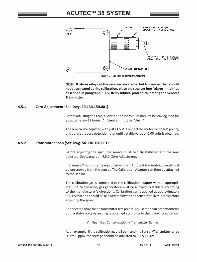
Prior to calibration, remove the cover from the Sensor/Transmitter enclosure and connect a DVM to the test points as shown in Figure 4.1. The test points will provide a 0-1.00 Vdc signal proportional to transmitter range. For example, a range of 0 to 10 ppm, 0 ppm is 0.00 volts and 10.0 ppm is 1.00 volts.
WT.050.130.000.UA.IM.0614
ACUTEC™ 35 SYSTEM
37 EVOQUA W3T129671
Figure 4.1 - Sensor/Transmitter Enclosure
NOTE: If alarm relays at the receiver are connected to devices that should not be activated during calibration, place the receiver into “alarm inhibit” as described in paragraph 3.3.5, Relay Inhibit, prior to calibrating the Sensor/Transmitter.
4.5.1 Zero Adjustment (See Dwg. 50.130.150.001)
Before adjusting the zero, allow the sensor to fully stabilize by leaving it on for approximately 12 hours. Ambient air must be “clean”.
The zero can be adjusted with just a DVM. Connect the meter to the test points, and adjust the zero potentiometer until a stable value of 0.00 volts is obtained.
4.5.2 Transmitter Span (See Dwg. 50.130.150.001)
Before adjusting the span, the sensor must be fully stabilized and the zero adjusted. See paragraph 4.5.1, Zero Adjustment.
If a Sensor/Transmitter is equipped with an Autotest Generator, it must first be unscrewed from the sensor. The Calibration Adapter can then be attached to the sensor.
The calibration gas is connected to the calibration adapter with an appropri-ate tube. When used, gas generators must be allowed to stabilize according to the manufacturer’s directions. Calibration gas is applied at approximately 500 cc/min and should be allowed to flow to the sensor for 10 minutes before adjusting the span.
Connect the DVM to the transmitter test points. Adjust the span potentiometer until a stable voltage reading is obtained according to the following equation:
V = Span Gas Concentration ÷ Transmitter Range
As an example, if the calibration gas is 3 ppm and the Sensor/Transmitter range is 0 to 5 ppm, the voltage should be adjusted to 3 ÷ 5 = 0.6V.
WT.050.130.000.UA.IM.0614
ACUTEC™ 35 SYSTEM
38 EVOQUA W3T129671
If the receiver was placed in the “inhibit” mode prior to calibration, press the pushbutton switch on the receiver to return the system to normal operation.
4.5.3 Range Adjustment (See Dwg. 50.130.150.001)
Sensor/Transmitters are factory calibrated at the Standard Ranges as listed in Section 1.1 – Technical Data, but can be changed within the limits listed in that Section.
The range can be changed by first setting the range configuration switches, C1 to C4, in the Receiver Module as described in paragraph 3.2, Receiver Module Operation. The transmitter span must then be adjusted as described above.
4.6 Battery Replacement (See Dwg. 50.130.000.003)
WARNING: TO AVOID POSSIBLE SEVERE PERSONAL INJURY OR EQUIP-MENT DAMAGE, HANDLE BATTERIES WITH CARE, BEING CERTAIN NOT TO SHORT TERMINALS, AS SEVERE ARCING OR EXPLOSION COULD OCCUR.
Remove the battery enclosure cover. Pull the plug off the circuit board. Cut the strap holding the battery in place, then pull the battery out. Slide circuit board off battery terminals.
To install the new battery, reverse above procedure. A new strap is supplied with replacement batteries. The battery should be installed with the terminals to the rear of the enclosure.
4.7 Routine Service
WARNING: TO AVOID POSSIBLE SEVERE PERSONAL INJURY OR EQUIP-MENT DAMAGE, DUE TO UNDETECTED LEAKS OF DANGEROUS GAS, THE FOLLOWING SERVICE MUST BE PERFORMED TO VERIFY OPERATION OF THIS GAS DETECTOR.
• MONTHLY
a. Test sensor response with actual gas if Autotest Generator is not in-stalled. However, if a higher degree of confidence is desired, the sensor may be tested more often.
b. Adjust sensor zero potentiometer.
c. Clean battery vent.
d. Verify that the Battery Back-up works by removing ac power.
!
!
WT.050.130.000.UA.IM.0614
ACUTEC™ 35 SYSTEM
39 EVOQUA W3T129671
• QUARTERLY
Adjust the sensor span potentiometer (optional—requires a gas calibration device). (Not supplied by Evoqua Water Technologies.)
NOTE: Span adjustment is recommended only when a precise indication of gas level is required.
4.8 Troubleshooting
Trouble Remedy
Receiver LEDs and indicators do not light when power is applied to the system.
1. Check the fuse. If the fuse is blown, replace the fuse. If not, go to step 2.
2. Check wiring from the Power Supply Module to the Receiver Module (see Dwgs. 50.130.130.001 and 50.130.130.002). Be sure polarity is correct. If wiring is correct, go to step 3.
3. With a voltmeter, check the power supply at the “+12” termi-nal (positive) and “C” terminal (negative) on the Receiver. If the reading is between 13.6 to 13.9 Vdc, replace the Receiver. If the voltage is above 13.9 V, go to step 5. If the voltage is below 13.6 V, go to step 4.
4. Measure the ac input voltage at the Power Supply Module. If the voltage is not within the rated range (see Section 1.1 - Technical Data), check ac supply. If the voltage is within the rated range, replace the Power Supply Module.
5. If the voltage measured in step 3 is above 13.9 V, connect another Receiver Module or a resistive load of approximately 100 ohm and 2 watts to the Power Supply output terminals. If the voltage drops to within 13.6 - 13.9 V, replace the Receiver. If not, replace the Power Supply Module.
Receiver module powers up correctly, but does not respond when test gas is applied to sensor/transmitter.
1. Disconnect the Transmitter connections at the two “TR” termi-nals of the Receiver. Check the voltage on the terminals with a voltmeter. The voltage should be approximately 12 Vdc. If this voltage is not present, replace the Receiver Module. If it is measured, go to step 2.
2. Connect a milliamp meter between the two “TR” terminals of the Receiver. The current should be 15 to 25 mA. If this current is not measured, replace the Receiver Module. If it is measured, refer to the Sensor/Transmitter paragraphs in this Section.
WT.050.130.000.UA.IM.0614
ACUTEC™ 35 SYSTEM
40 EVOQUA W3T129671
WARNING LABELS AND TAGS
The following warning labels and tags are attached to the equipment.
----------------------------------------------------------------------------------------------------P60391: Gases detected are hazardous substances, and if breathed in high
concentrations can cause death. To maintain normal operation of this detector you must observe the following precautions.1. DETECTOR OPERATION MUST BE CHECKED AND VERIFIED
FREQUENTLY ON A REGULAR SCHEDULE.2. To avoid injury from electrical shock, turn power sources off
before servicing this equipment.3. The Evoqua Water Technologies instruction book provided
with this detector DETAILS installation, operation and main-tenance.
4. Operation AND maintenance of this equipment must be restricted to trained, qualified personnel who are completely familiar with these instructions.
----------------------------------------------------------------------------------------------------P60402: PERSONAL INJURY OR DEATH MAY RESULT FROM EXPOSURE TO
THE DESIGNATED GAS. TEST ASSEMBLY WITH DESIGNATED GAS UPON START-UP, MONTHLY, AND IF EXPOSED TO CHEMICALS. REPLACE OR REPAIR ASSEMBLY IMMEDIATELY UPON TEST FAIL-URE. REFER TO THE EVOQUA WATER TECHNOLOGIES MANUAL.
----------------------------------------------------------------------------------------------------P60392: *TO AVOID INJURY FROM ELECTRICAL ARCING, TURN POWER
SOURCES OFF BEFORE SERVICING THIS EQUIPMENT.----------------------------------------------------------------------------------------------------
CAUTION LABEL
The following caution label is attached to the equipment.----------------------------------------------------------------------------------------------------P60392: *LEAD ACID BATTERY, DISPOSE OF PROPERLY.----------------------------------------------------------------------------------------------------* Both on same label.
WT.050.130.000.UA.IM.0614
ACUTEC™ 35 SYSTEM
41 EVOQUA W3T129671
SENSOR/TRANSMITTER - SERVICE
50.130.150.001ISSUE 0 11-93

WT.050.130.000.UA.IM.0614
ACUTEC™ 35 SYSTEM
42 EVOQUA W3T129671

WT.050.130.000.UA.IM.0614
ACUTEC™ 35 SYSTEM
43 EVOQUA W3T129671
SECTION 5 – ILLUSTRATIONS
List Of Contents
DRAWING NO.
Parts Gas Detector System ................................................... 50.130.000.001A&B Sensor/Transmitter Unit ............................................. 50.130.000.002 U29319 Battery Back-Up ............................................. 50.130.000.003
WT.050.130.000.UA.IM.0614
ACUTEC™ 35 SYSTEM
44 EVOQUA W3T129671
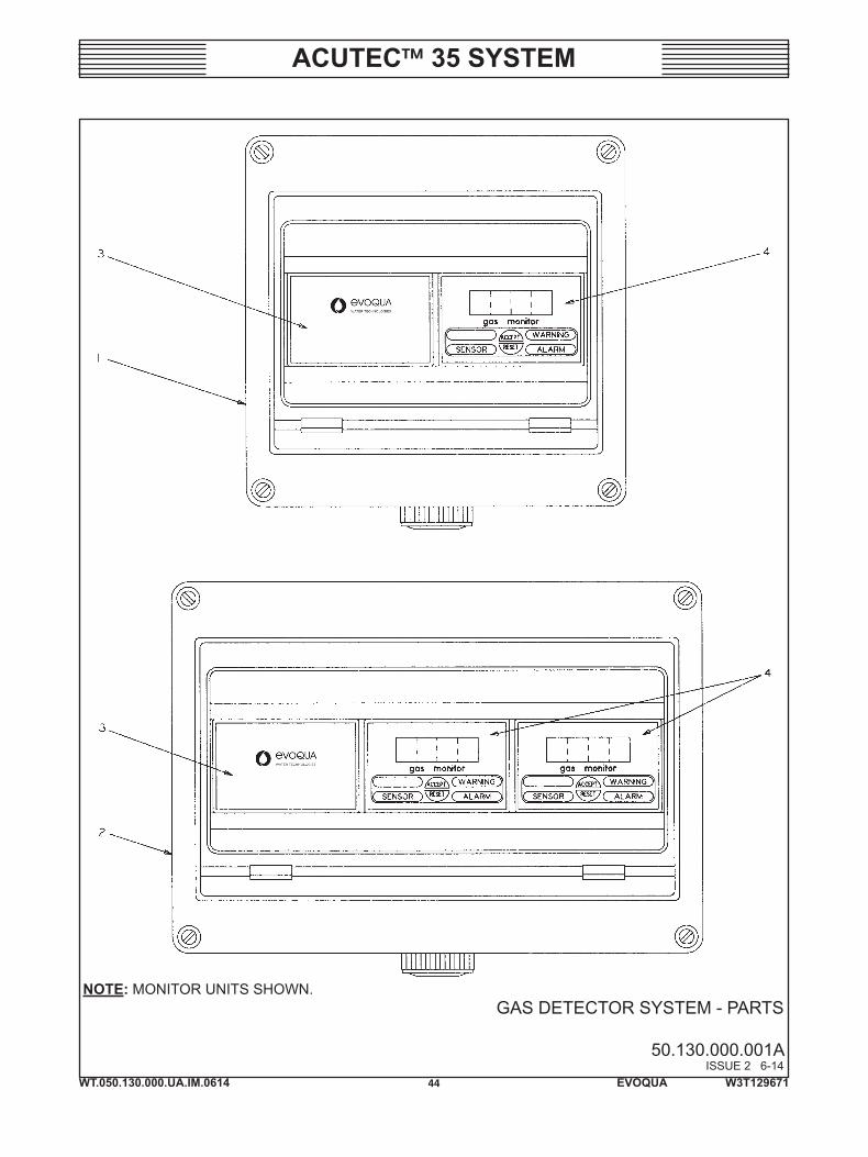
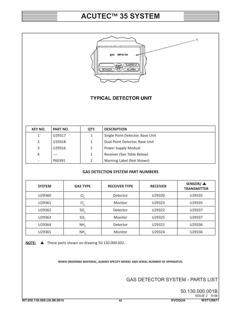
GAS DETECTOR SYSTEM - PARTS
50.130.000.001AISSUE 2 6-14
NOTE: MONITOR UNITS SHOWN.
WT.050.130.000.UA.IM.0614
ACUTEC™ 35 SYSTEM
45 EVOQUA W3T129671
GAS DETECTOR SYSTEM - PARTS LIST
50.130.000.001BISSUE 2 8-08
WHEN ORDERING MATERIAL, ALWAYS SPECIFY MODEL AND SERIAL NUMBER OF APPARATUS.
KEY NO. PART NO. QTY. DESCRIPTION
1 U29317 1 Single Point Detector, Base Unit
2 U29318 1 Dual Point Detector, Base Unit
3 U29316 1 Power Supply Modual
4 ---- 1 Receiver (See Table Below)
- P60391 2 Warning Label (Not Shown)
GAS DETECTION SYSTEM PART NUMBERS
SYSTEM GAS TYPE RECEIVER TYPE RECEIVERSENSOR/
TRANSMITTER
U29360 Cl2 Detector U29320 U29335
U29361 Cl2 Monitor U29323 U29335
U29362 SO2 Detector U29322 U29337
U29363 SO2 Monitor U29325 U29337
U29364 NH3 Detector U29321 U29336
U29365 NH3 Monitor U29324 U29336
NOTE: These parts shown on drawing 50.130.000.002.
WT.050.130.000.UA.IM.0614
ACUTEC™ 35 SYSTEM
46 EVOQUA W3T129671
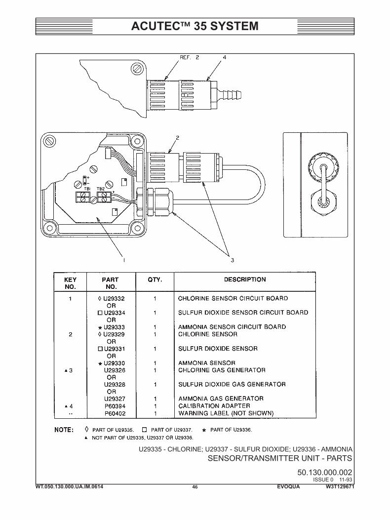
U29335 - CHLORINE; U29337 - SULFUR DIOXIDE; U29336 - AMMONIASENSOR/TRANSMITTER UNIT - PARTS
50.130.000.002ISSUE 0 11-93
WT.050.130.000.UA.IM.0614
ACUTEC™ 35 SYSTEM
47 EVOQUA W3T129671
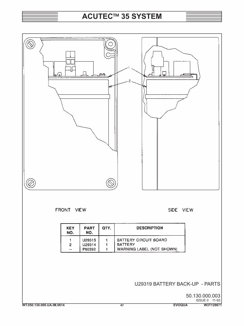
U29319 BATTERY BACK-UP - PARTS
50.130.000.003ISSUE 0 11-93

WT.050.130.000.UA.IM.0614
ACUTEC™ 35 SYSTEM
48 EVOQUA W3T129671

WT.050.130.000.UA.IM.0614
ACUTEC™ 35 SYSTEM
49 EVOQUA W3T129671
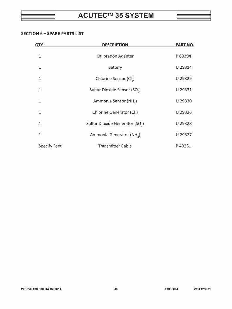
SECTION 6 – SPARE PARTS LIST
QTY DESCRIPTION PART NO.
1 Calibration Adapter P 60394
1 Battery U 29314
1 Chlorine Sensor (Cl2) U 29329
1 Sulfur Dioxide Sensor (SO2) U 29331
1 Ammonia Sensor (NH3) U 29330
1 Chlorine Generator (Cl2) U 29326
1 Sulfur Dioxide Generator (SO2) U 29328
1 Ammonia Generator (NH3) U 29327
Specify Feet Transmitter Cable P 40231