Embed Size (px)
Citation preview
The Cambered Panel Junk Rig, by Arne Kverneland Chapter 3, ver. 20140224
1(23)
Chapter 3 (..of The Cambered Panel Junk Rig...)
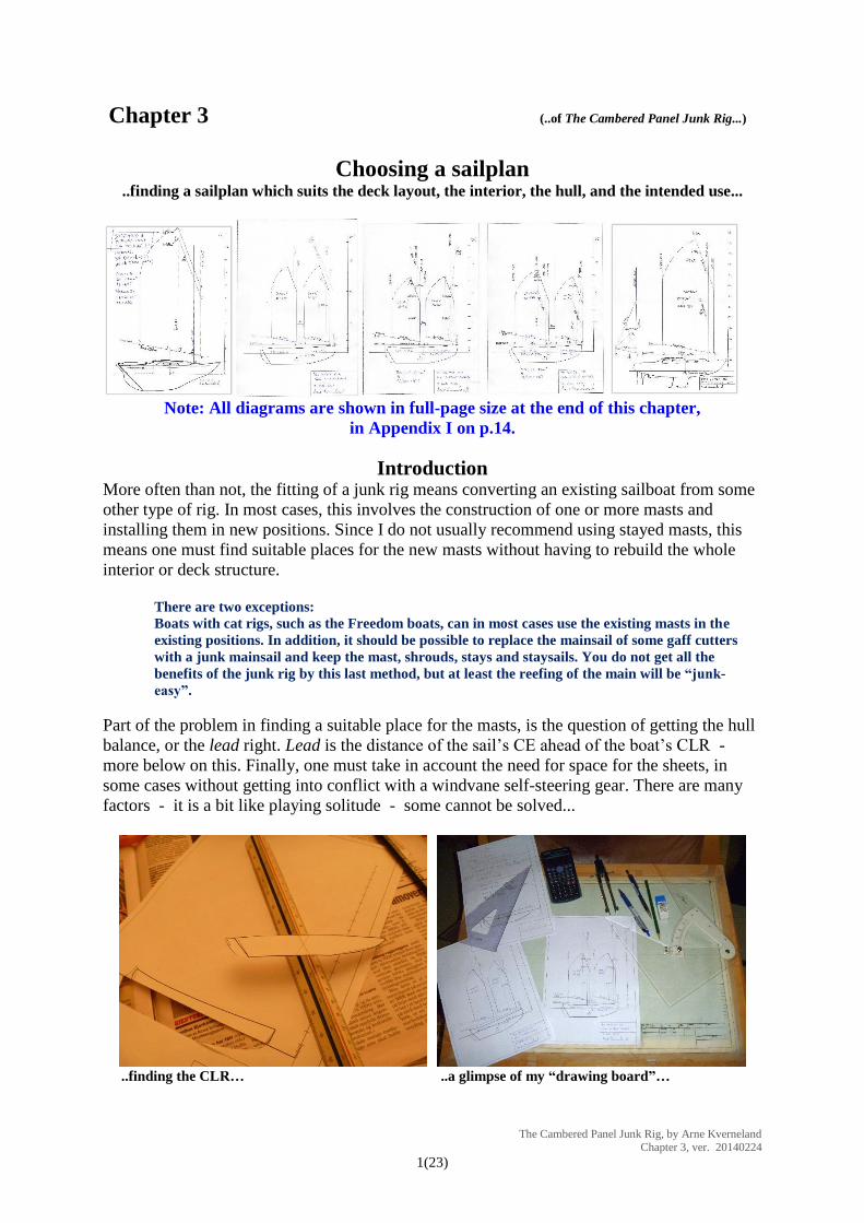
Choosing a sailplan ..finding a sailplan which suits the deck layout, the interior, the hull, and the intended use...
Note: All diagrams are shown in full-page size at the end of this chapter,
in Appendix I on p.14.
Introduction More often than not, the fitting of a junk rig means converting an existing sailboat from some
other type of rig. In most cases, this involves the construction of one or more masts and
installing them in new positions. Since I do not usually recommend using stayed masts, this
means one must find suitable places for the new masts without having to rebuild the whole
interior or deck structure.
There are two exceptions:
Boats with cat rigs, such as the Freedom boats, can in most cases use the existing masts in the
existing positions. In addition, it should be possible to replace the mainsail of some gaff cutters
with a junk mainsail and keep the mast, shrouds, stays and staysails. You do not get all the
benefits of the junk rig by this last method, but at least the reefing of the main will be “junk-
easy”.
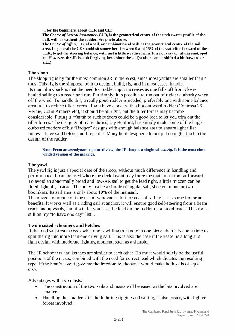
Part of the problem in finding a suitable place for the masts, is the question of getting the hull
balance, or the lead right. Lead is the distance of the sail’s CE ahead of the boat’s CLR -
more below on this. Finally, one must take in account the need for space for the sheets, in
some cases without getting into conflict with a windvane self-steering gear. There are many
factors - it is a bit like playing solitude - some cannot be solved...
..finding the CLR… ..a glimpse of my “drawing board”…
The Cambered Panel Junk Rig, by Arne Kverneland Chapter 3, ver. 20140224
2(23)
(.. for the beginners, about CLR and CE:
The Centre of Lateral Resistance, CLR, is the geometrical centre of the underwater profile of the
hull, with or without the rudder. See photo above.
The Centre of Effort, CE, of a sail, or combination of sails, is the geometrical centre of the sail
area. In general the CE should sit somewhere between 0 and 15% of the waterline forward of the
CLR, to get the steering balance, with just a little weather helm. It is not easy to hit this lead, spot
on. However, the JR is a bit forgiving here, since the sail(s) often can be shifted a bit forward or
aft...)
The sloop
The sloop rig is by far the most common JR in the West, since most yachts are smaller than 4
tons. This rig is the simplest, both to design, build, rig, and in most cases, handle.
Its main drawback is that the need for rudder input increases as one falls off from close-
hauled sailing to a reach and run. Put simply, it is possible to run out of rudder authority when
off the wind. To handle this, a really good rudder is needed, preferably one with some balance
area in it to reduce tiller forces. If you have a boat with a big outboard rudder (Contessa 26,
Vertue, Colin Archers etc), it should be all right, but the tiller forces may become
considerable. Fitting a trimtab to such rudders could be a good idea to let you trim out the
tiller forces. The designer of many dories, Jay Benford, has simply made some of the large
outboard rudders of his “Badger” designs with enough balance area to ensure light tiller
forces. I have said before and I repeat it: Many boat designers do not put enough effort in the
design of the rudder.
Note: From an aerodynamic point of view, the JR sloop is a single sail cat rig. It is the most close-
winded version of the junkrigs.
The yawl
The yawl rig is just a special case of the sloop, without much difference in handling and
performance. It can be used where the deck layout may force the main mast too far forward.
To avoid an abnormally broad and low-AR sail to get the lead right, a little mizzen can be
fitted right aft, instead. This may just be a simple triangular sail, sheeted to one or two
boomkins. Its sail area is only about 10% of the mainsail.
The mizzen may rule out the use of windvanes, but for coastal sailing it has some important
benefits: It works well as a riding sail at anchor, it will ensure good self-steering from a beam
reach and upwards, and it will let you ease the load on the rudder on a broad reach. This rig is
still on my “to have one day” list...
Two-masted schooners and ketches
If the total sail area exceeds what one is willing to handle in one piece, then it is about time to
split the rig into more than one driving sail. This is also the case if the vessel is a long and
light design with moderate righting moment, such as a sharpie.
The JR schooners and ketches are similar to each other. To me it would solely be the useful
positions of the masts, combined with the need for correct lead which dictates the resulting
type. If the boat’s layout gave me the freedom to choose, I would make both sails of equal
size.
Advantages with two masts:
The construction of the two sails and masts will be easier as the bits involved are
smaller.
Handling the smaller sails, both during rigging and sailing, is also easier, with lighter
forces involved.
The Cambered Panel Junk Rig, by Arne Kverneland Chapter 3, ver. 20140224
3(23)
Splitting the sail area will let one trim the sails to give optimum balance, both when
close-hauled and when reaching. As long as both sails work, this will put lighter loads
on the rudder.
Running before in light winds, the sails can be set to each side, which will give good
drive and easy steering.
Running before, offshore, in some wind and swell, can be done by sheeting the
foresail amidships and let the squared out aft sail (main/mizzen) drive the boat. This
will both reduce rolling and keep the boat from rounding up (source: Annie Hill in
Badger). Others prefer to stow the aft sail and only sail on the foresail.
If one of the sails or masts fails, there is a chance of getting home with the one
remaining mast. See note below.
Disadvantages with two masts:
Cost. The number of bits will be double of that on a sloop rig. Even though those bits
are smaller, they will cost more in money and work, to buy or to make.
Avoiding sheet tangle at the foresail is often a problem. The gap between the two sails
tends to be on the short side, which may lead to very steep sheet angles. It may be
necessary to sheet one or both sails to runners or use port-starboard sheeting. More
ropes, more blocks.
The foresail is mostly hidden forward of the mainsail, which makes it awkward to see
it and trim it correctly.
I would reckon the two-sail junk, schooner or ketch, to be a little less close-winded
than the JR sloop. Still, remember that aerodynamically, these rigs are nothing but
two-stick sloops and will normally sail better to windward than Bermuda or gaff
ketches and schooners. These generally set 3 - 5 sails in front of each other so cannot
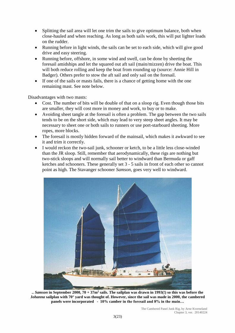
point as high. The Stavanger schooner Samson, goes very well to windward.
.. Samson in September 2000, 70 + 37m2 sails. The sailplan was drawn in 1993(!) so this was before the
Johanna sailplan with 70° yard was thought of. However, since the sail was made in 2000, the cambered
panels were incorporated - 10% camber in the foresail and 8% in the main…
The Cambered Panel Junk Rig, by Arne Kverneland Chapter 3, ver. 20140224
4(23)
NOTE: To make use of the dual mast redundancy of these rigs, one of two conditions has
to be present:
1. One may have a movable CLR, usually by having two centreboards, one well forward
and one way aft. This has been seen on some large American cruisers.
2. The only other alternative is to fit a large and effective rudder, at least as big as that
needed on a sloop.
I have been lucky to sail a lot in Folkboats, both the Nordic and the International - NF and
IF. The International Folkboat has a mainsail of 16m2 and the working jib of 10m2. She tacks
to windward with only that small jib set, thanks to the easily driven hull and the really big
keel and rudder. I wouldn’t want to make a long voyage to windward with that little sail and
with the resultant lee helm, but at least we could save ourselves from a lee shore if the main
halyard should break and the engine refused to start. Under main alone, that IF performs quite
well, although the weather helm can be felt. My point in writing this is that it helps little with
two sails if the boat cannot manoeuvre and sail a bit to windward with any one of the two sails
out of action.
(.. I shudder when thinking of all the wrecks from sailing ships that are spread around our coasts.
Often their crew lost control of the ship because some sail blew out in one end of the ship, and the
relatively tiny rudders could not force the ship back on course...)
..and now to the sketching procedure...
Sketching up a sloop rig
There are many different styles or shapes of sailplans in use. Some of you are completely
confident on how to draw your favourite JR. Good! When I decided to write only about the
Johanna style rig in this chapter, it is simply because I know it so well. This write-up is for the
first-timers who just need a quick and easy way to produce a usable sailplan. Since I am aiming
for DIY sailmakers, I encourage you to draw with pen on paper (..in these days of CAD…), as this
method more resembles the lofting and cutting you will do later on.
This sketching procedure is meant to enable you to quickly sketch rigs on different boats, or
on a boat with several possible mast positions in mind. As long as you stick to the Johanna
style version of the Hasler-McLeod rig, you will be able to calculate its sail area (SA), centre
of effort (CE) and aspect ratio (AR) without having to draw any sail in detail.
The Johanna style sail has these characteristics:
The boom (foot), battens and yard (head) are of the same length
The boom rise is 10°
The yard angle is 70°
The panels are counted/numbered from top.
Panel 3 is the transition panel. I use this panel in the final design process to ensure that
all panels end up at about the same area. More about this in Chapter 4.
I generally prefer to have the luff and leech rigged to be vertical. This is mainly to get
trouble-free sheeting.
With the aspect ratio between 1.80 and 2.25 I make the sail from 7 panels of about
equal area in each.
The Cambered Panel Junk Rig, by Arne Kverneland Chapter 3, ver. 20140224
5(23)
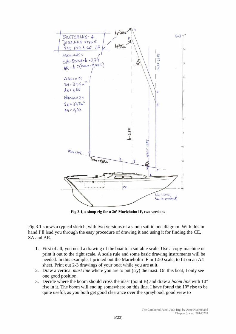
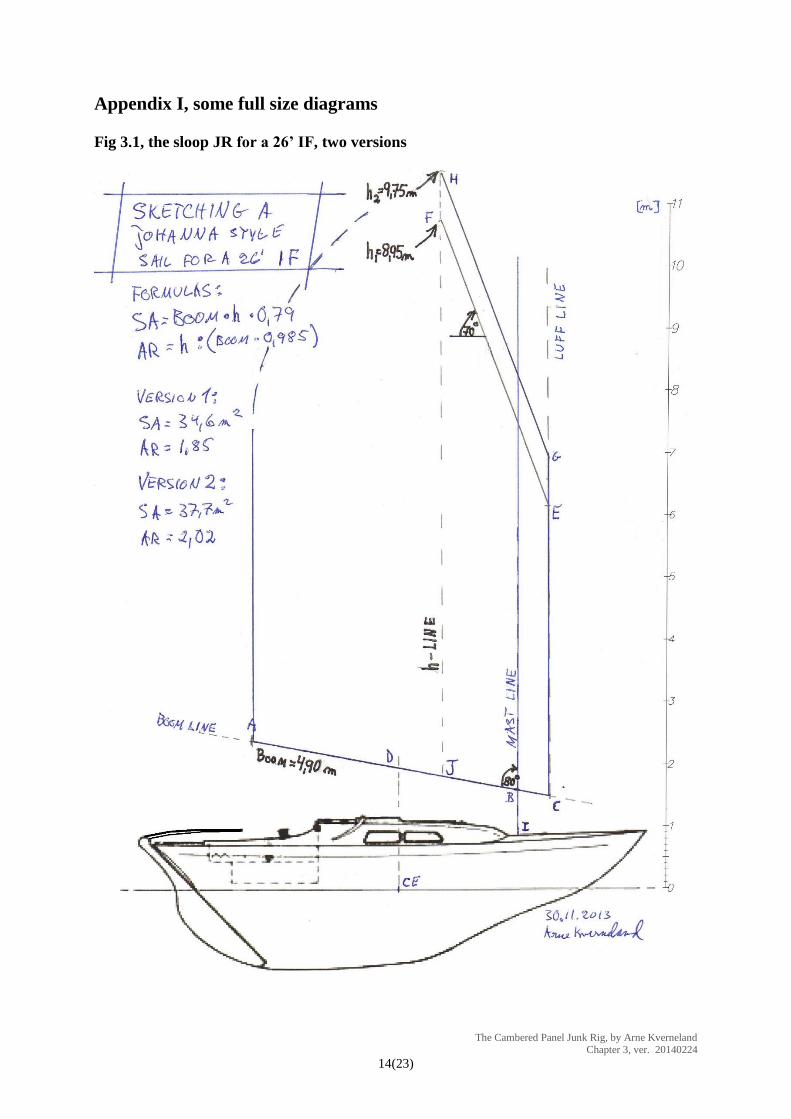
Fig 3.1, a sloop rig for a 26’ Marieholm IF, two versions
Fig 3.1 shows a typical sketch, with two versions of a sloop sail in one diagram. With this in
hand I’ll lead you through the easy procedure of drawing it and using it for finding the CE,
SA and AR.
1. First of all, you need a drawing of the boat to a suitable scale. Use a copy-machine or
print it out to the right scale. A scale rule and some basic drawing instruments will be
needed. In this example, I printed out the Marieholm IF in 1:50 scale, to fit on an A4
sheet. Print out 2-3 drawings of your boat while you are at it.
2. Draw a vertical mast line where you are to put (try) the mast. On this boat, I only see
one good position.
3. Decide where the boom should cross the mast (point B) and draw a boom line with 10°
rise in it. The boom will end up somewhere on this line. I have found the 10° rise to be
quite useful, as you both get good clearance over the sprayhood, good view to
The Cambered Panel Junk Rig, by Arne Kverneland Chapter 3, ver. 20140224
6(23)
leeward, and you avoid a drooping boom when the sail is reefed or furled. With good
clearance, there is no need for adjusting the topping lifts under way.
4. Decide where the horizontal position of the CE of the sail should sit, relative to the
CLR. This is often easier said than done. Here I have started with the CE of the
Bermuda rig (BR), and then selected a point about 4-6% of the WL further aft. Then
draw a short vertical line through CE, to cross the boom line at D.
5. The CE in a Johanna style sail: Now here is a convenient trick: Experience has
shown that the CE of these sails ends almost exactly over the centre of the boom. This
lets us now draw the boom. To find a suitable boom, all we have to do is to draw half
of it aft of and half of it forward of D. In addition, the boom has to pass the mast so
that it is has around 10% of its length forward of the mast. The resulting 4.90m boom
is between A and C in Fig 3.1. Later, when on the boat you will be free to position the
sail with the balance varying between 5 and 15% (.. 10% balance means here that 10% of the
chord of the sail is forward of the mast...)
6. From the tack, C, draw a vertical luff line and make it quite long.
7. Now it is time to try a yard position: From the luff, draw a tentative yard with 70°
peaking and the same length as the boom. My first yard effort here was the E-F yard
8. Finally, draw a vertical height line (“h-line”) from the peak F down to where it crosses
the boom at J.
Job done, so far. With these lines in place, we can calculate both the sail area and aspect
ratio, using these formulas:
Sail Area, SA= boom x h x ”The Johanna Sail Area Factor” = boom x h x 0.79
(.. if this formula is to be used with the chord instead of the 10° boom, the formula is:
𝑺𝑨 = 𝑪𝒉𝒐𝒓𝒅 × 𝒉 × 𝟎. 𝟖𝟎 … )
Aspect Ratio, 𝑨𝑹 = 𝒉 ÷ 𝒄𝒉𝒐𝒓𝒅 [ = h ÷ (boom x cos10°) = h ÷ (boom x 0.985) ] )
I have found this SA factor, 0.79 or 0.80, by checking a number of sails with varying ARs, but
all of them to the Johanna style rules above. With sails in this size range, the error will
generally be within 1m².
The brilliant thing with this method is that we both get a glimpse of the sail as well as finding
the sail area, all without having drawn the whole sail first. Of course, an Excel program could
do this even better, but again, this semi-manual method is closer to lofting the sail.
In my case I ended up with two different versions, one suggesting a SA= 34.6m2 and the other
SA=37.7m2. The leech is not really needed for this rough sketch, but I have added it later,
more or less by free hand.
If you want to try out several mast positions, I suggest you start on a clean sheet for each of
them, otherwise the drawings can easily become confusing.
Sketching up some schooner rigs
The quick way of sketching up a sloop rig is even more useful if you plan a two-masted rig.
The suggested procedure is rather a slightly retouched account of how I stumbled my way
through it (.. surprise, surprise...).
Note: A few of you may find your skills in maths to be a bit rusty. Then have a look in the
Appendix II of this chapter.

The Cambered Panel Junk Rig, by Arne Kverneland Chapter 3, ver. 20140224
7(23)
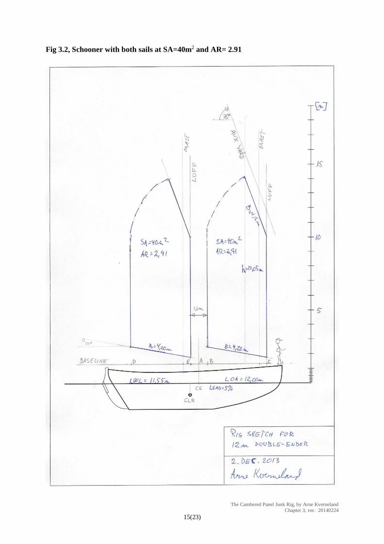
See Fig 3.2 and 3.3, below. This time I have made a quick CAD sketch of an imaginary hull:
Imagine it to be a trim double-ender with LOA=12.00m, LWL=11.55m, beam=3.00m,
draught=1.80m and displacement=12000kg. I aim for a SA=80m², giving a SA/disp= 14.9.
Both these rigs are special cases, being schooners with both the mainsail and foresail of the
same size and shape. This time I feel free to put the masts where I like (a rare luxury) and I
have only one absolute rule: The distance between the sails is to be at least 1.0 metre.
In my first attempt (Fig 3.2, below) I tried to make a rig with some foredeck space and good
sheeting clearance for the mainsail as well. However, to achieve the needed 80m² sail area,
the sails ended up super tall, with AR=2.91. This will lead to extremely steep sheeting angles
and would almost certainly call for sheet tracks or separate port-starboard sheeting. This is not
my favourite setup.
Fig 3.2, Schooner with both sails at SA=40m2
and AR= 2.91
The Cambered Panel Junk Rig, by Arne Kverneland Chapter 3, ver. 20140224
8(23)
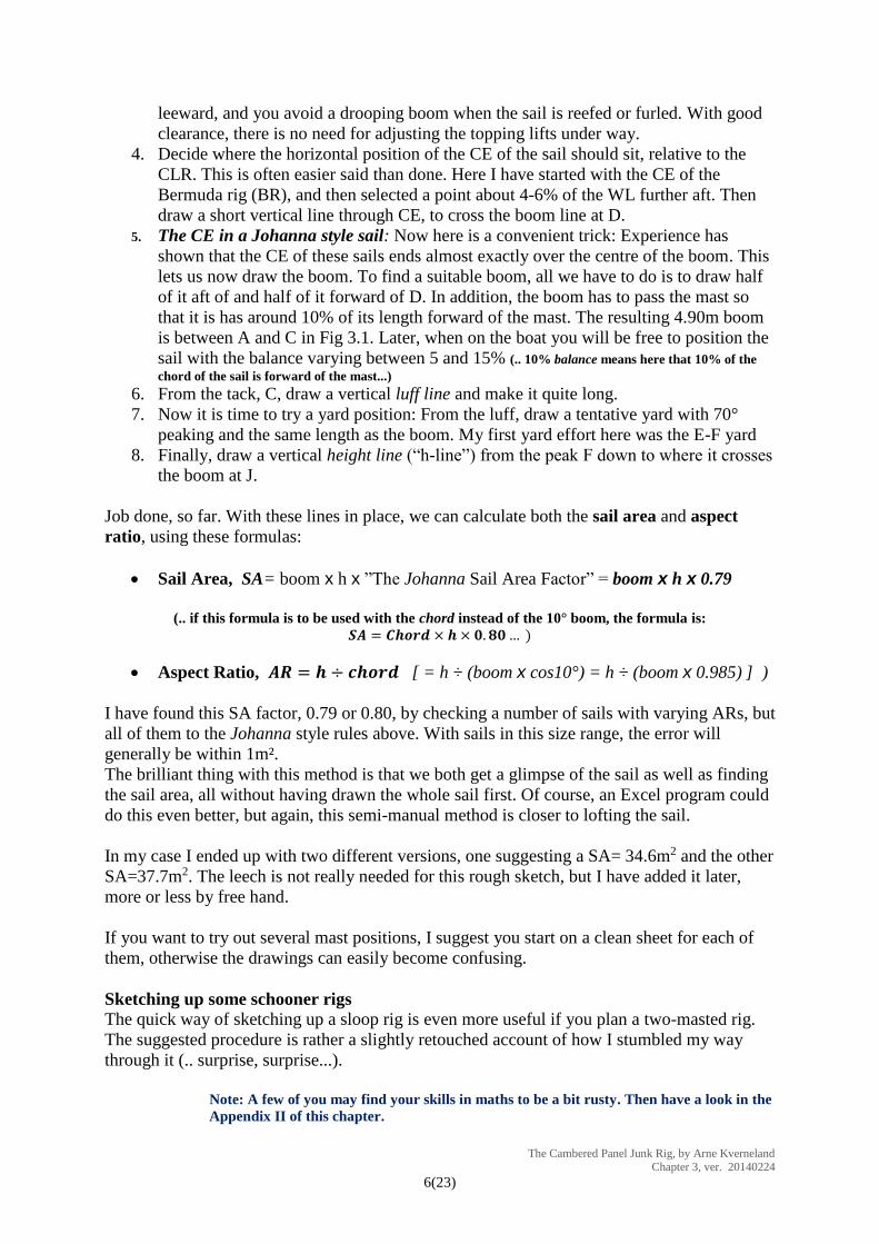
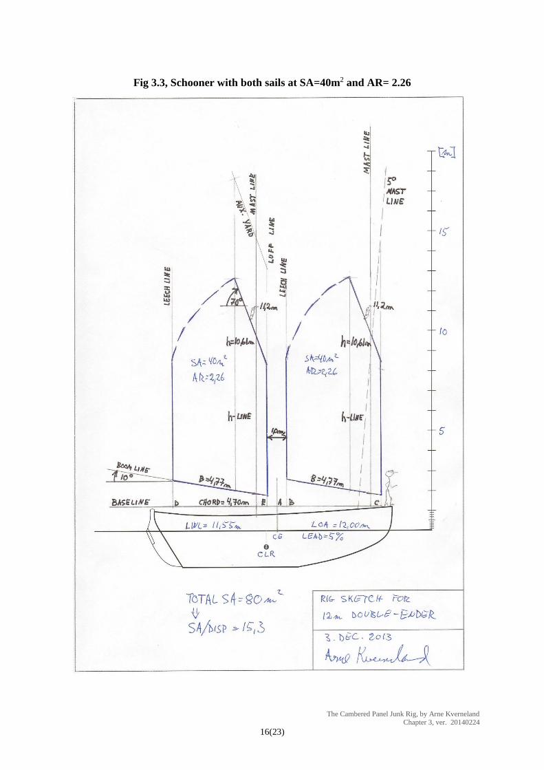
In my second attempt (Fig 3.3, below) I increased the boom length, B, from 4.20m to 4.77m.
When going through the drawing sequence, I suggest you keep Fig 3.3 at hand, as this has
more details on it than Fig 3.2 (..and because I like this rig better…).
Fig 3.3, Schooner with both sails at SA=40m
2 and AR= 2.26
The Cambered Panel Junk Rig, by Arne Kverneland Chapter 3, ver. 20140224
9(23)
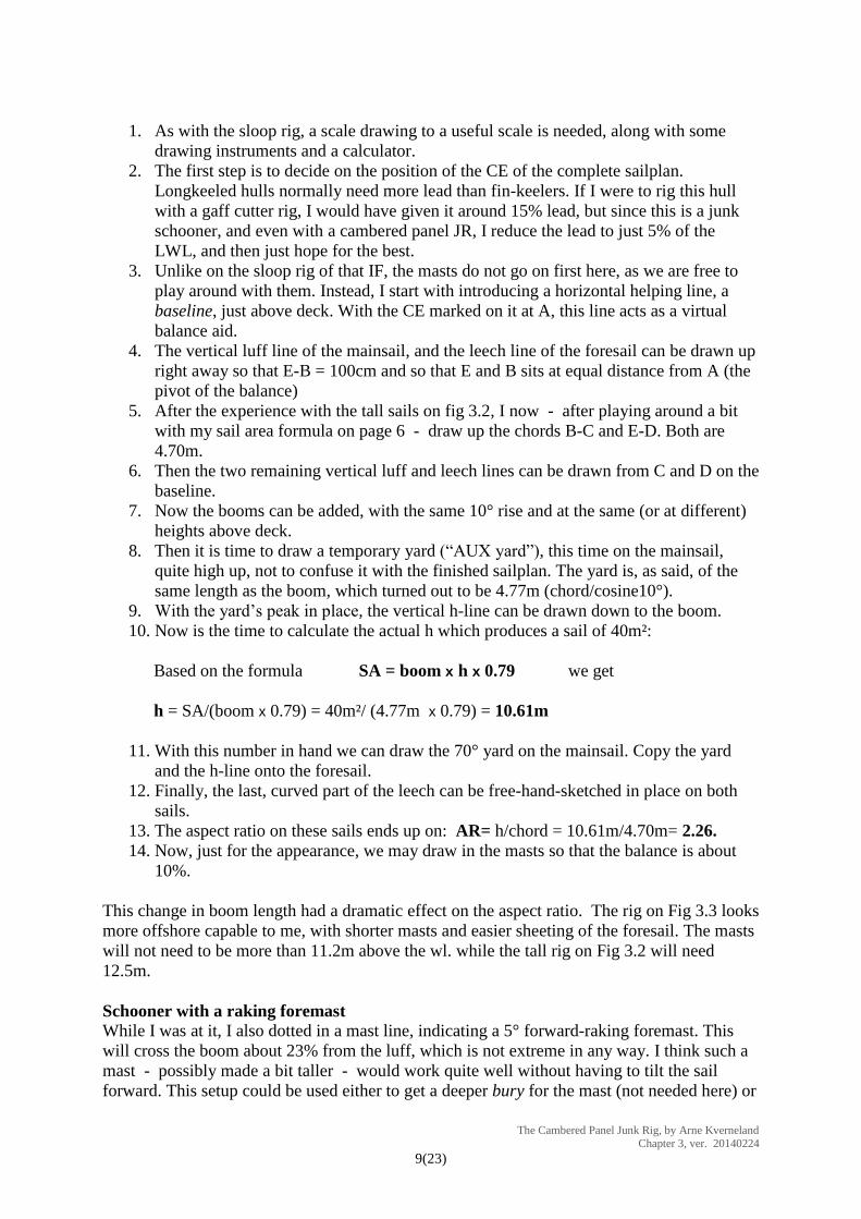
1. As with the sloop rig, a scale drawing to a useful scale is needed, along with some
drawing instruments and a calculator.
2. The first step is to decide on the position of the CE of the complete sailplan.
Longkeeled hulls normally need more lead than fin-keelers. If I were to rig this hull
with a gaff cutter rig, I would have given it around 15% lead, but since this is a junk
schooner, and even with a cambered panel JR, I reduce the lead to just 5% of the
LWL, and then just hope for the best.
3. Unlike on the sloop rig of that IF, the masts do not go on first here, as we are free to
play around with them. Instead, I start with introducing a horizontal helping line, a
baseline, just above deck. With the CE marked on it at A, this line acts as a virtual
balance aid.
4. The vertical luff line of the mainsail, and the leech line of the foresail can be drawn up
right away so that E-B = 100cm and so that E and B sits at equal distance from A (the
pivot of the balance)
5. After the experience with the tall sails on fig 3.2, I now - after playing around a bit
with my sail area formula on page 6 - draw up the chords B-C and E-D. Both are
4.70m.
6. Then the two remaining vertical luff and leech lines can be drawn from C and D on the
baseline.
7. Now the booms can be added, with the same 10° rise and at the same (or at different)
heights above deck.
8. Then it is time to draw a temporary yard (“AUX yard”), this time on the mainsail,
quite high up, not to confuse it with the finished sailplan. The yard is, as said, of the
same length as the boom, which turned out to be 4.77m (chord/cosine10°).
9. With the yard’s peak in place, the vertical h-line can be drawn down to the boom.
10. Now is the time to calculate the actual h which produces a sail of 40m²:
Based on the formula SA = boom x h x 0.79 we get
h = SA/(boom x 0.79) = 40m²/ (4.77m x 0.79) = 10.61m
11. With this number in hand we can draw the 70° yard on the mainsail. Copy the yard
and the h-line onto the foresail.
12. Finally, the last, curved part of the leech can be free-hand-sketched in place on both
sails.
13. The aspect ratio on these sails ends up on: AR= h/chord = 10.61m/4.70m= 2.26.
14. Now, just for the appearance, we may draw in the masts so that the balance is about
10%.
This change in boom length had a dramatic effect on the aspect ratio. The rig on Fig 3.3 looks
more offshore capable to me, with shorter masts and easier sheeting of the foresail. The masts
will not need to be more than 11.2m above the wl. while the tall rig on Fig 3.2 will need
12.5m.
Schooner with a raking foremast
While I was at it, I also dotted in a mast line, indicating a 5° forward-raking foremast. This
will cross the boom about 23% from the luff, which is not extreme in any way. I think such a
mast - possibly made a bit taller - would work quite well without having to tilt the sail
forward. This setup could be used either to get a deeper bury for the mast (not needed here) or
The Cambered Panel Junk Rig, by Arne Kverneland Chapter 3, ver. 20140224
10(23)
one could move the mast forward to the vertical foremast’s position, and thus move the whole
sail. This again could let us build a rig with a bigger mainsail, while retaining the 40m²
foresail. Let us try that.
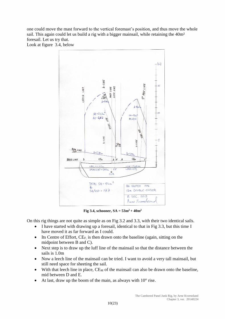
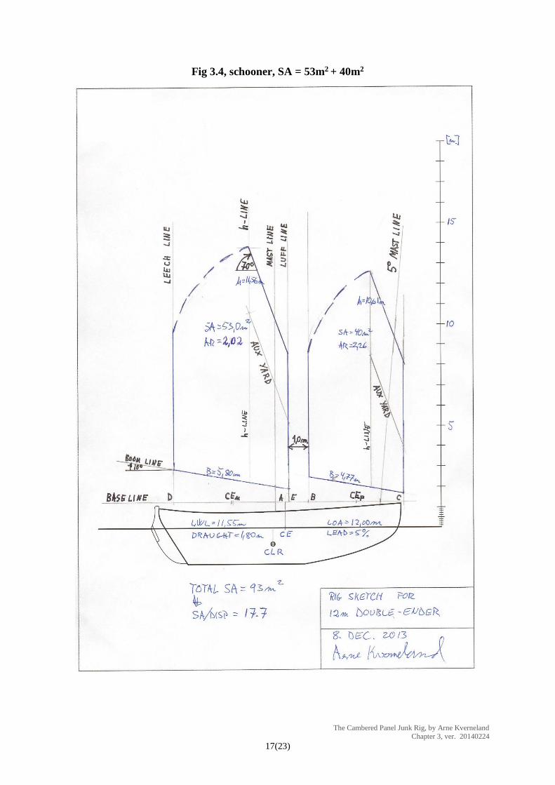
Look at figure 3.4, below
Fig 3.4, schooner, SA = 53m2 + 40m2
On this rig things are not quite as simple as on Fig 3.2 and 3.3, with their two identical sails.
I have started with drawing up a foresail, identical to that in Fig 3.3, but this time I
have moved it as far forward as I could.
Its Centre of Effort, CEF, is then drawn onto the baseline (again, sitting on the
midpoint between B and C).
Next step is to draw up the luff line of the mainsail so that the distance between the
sails is 1.0m
Now a leech line of the mainsail can be tried. I want to avoid a very tall mainsail, but
still need space for sheeting the sail.
With that leech line in place, CEM of the mainsail can also be drawn onto the baseline,
mid between D and E.
At last, draw up the boom of the main, as always with 10° rise.

The Cambered Panel Junk Rig, by Arne Kverneland Chapter 3, ver. 20140224
11(23)
With the position of the rig’s total CE (at A on the baseline) and also with the CEs of the two
sails in place, it is just a question of simple maths to decide the sail area needed in the
mainsail (..again, check Appendix II if needed…):
To be in balance, the area of a sail, multiplied by the distance of its CE from point A, must be
the same for both sails.
The two distances are: A-CEM = 2.64m and A-CEF = 3.50m (found by measuring)
Then...
𝑆𝐴𝑀𝑎𝑖𝑛 × 2.64𝑚 = 𝑆𝐴𝐹𝑜𝑟𝑒 × 3.50𝑚
which with 𝑆𝐴𝐹𝑜𝑟𝑒 = 40𝑚2 gives
𝑆𝐴𝑀𝑎𝑖𝑛 = 40 × 3.50 2.64⁄ = 53.0𝑚2
All we need then before we can sketch up the mainsail, is the height, h:
Since...
SA = boom x h x 0.79
then...
ℎ = 𝑆𝐴 (𝐵𝑜𝑜𝑚 × 0.79)⁄ = 53 (5.80 × 0.79)⁄ = 11.56𝑚
Finally we can find the mainsail’s aspect ratio:
AR = h/ Chord = h/ ( Boom x cos10°) = 2.02
(If you can’t handle functions like sine, cosine etc, just measure the chord D-E on the
drawing - or check Appendix II…)
Then, as done before, a helping (“AUX”) yard is drawn to establish the h-line, and then the
position of the peak can be plotted in. The rest of the sketching job should now be plain
sailing..
NOTE: I actually tried with two other boom lengths, 5.7m and 5.9m, until I landed on
B=5.8m. However, I did not have to draw a number of sails, but just calculated the sail
areas and aspect ratios by using the formulas above.
In the sailplan in Fig 3.4 we have been able to squeeze in quite a bit more sail area than on the
rig in Fig 3.2 and 3.3. It does show that it is not easy to get in enough sail area with two masts
- quite a paradox, really. On boats that are heavy for their length, I would tend to go for a
sloop, even if it means I would need electric winches.
..Sebastian Hentschel’s Peregrine, racing...
The Cambered Panel Junk Rig, by Arne Kverneland Chapter 3, ver. 20140224
12(23)
Peregrine, shown above, is 37’ and 11.5 tons, with a sloop sail of 80m². Handling such a brute
takes stout gear, but both the boat and the rig have proven to be effective, inshore as well as
offshore. She now has an electric halyard winch and the sheet has two tails, one handling the
upper part and one the lower.
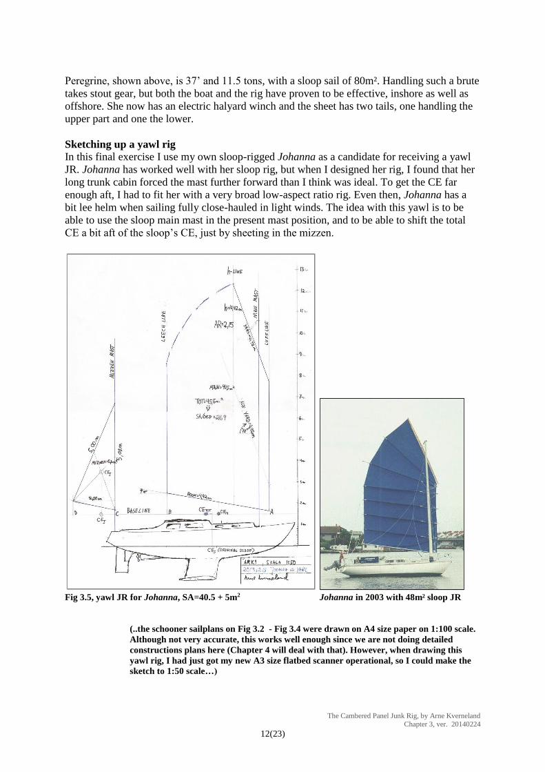
Sketching up a yawl rig
In this final exercise I use my own sloop-rigged Johanna as a candidate for receiving a yawl
JR. Johanna has worked well with her sloop rig, but when I designed her rig, I found that her
long trunk cabin forced the mast further forward than I think was ideal. To get the CE far
enough aft, I had to fit her with a very broad low-aspect ratio rig. Even then, Johanna has a
bit lee helm when sailing fully close-hauled in light winds. The idea with this yawl is to be
able to use the sloop main mast in the present mast position, and to be able to shift the total
CE a bit aft of the sloop’s CE, just by sheeting in the mizzen.
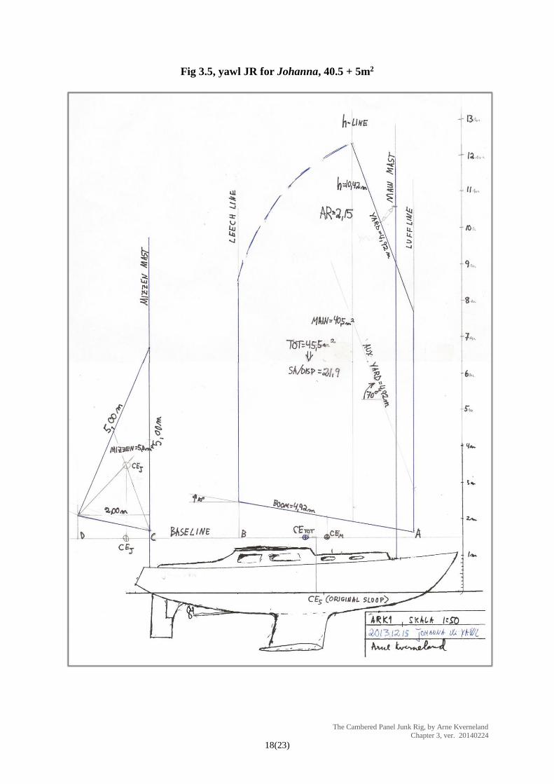
Fig 3.5, yawl JR for Johanna, SA=40.5 + 5m2 Johanna in 2003 with 48m² sloop JR
(..the schooner sailplans on Fig 3.2 - Fig 3.4 were drawn on A4 size paper on 1:100 scale.
Although not very accurate, this works well enough since we are not doing detailed
constructions plans here (Chapter 4 will deal with that). However, when drawing this
yawl rig, I had just got my new A3 size flatbed scanner operational, so I could make the
sketch to 1:50 scale…)
The Cambered Panel Junk Rig, by Arne Kverneland Chapter 3, ver. 20140224
13(23)
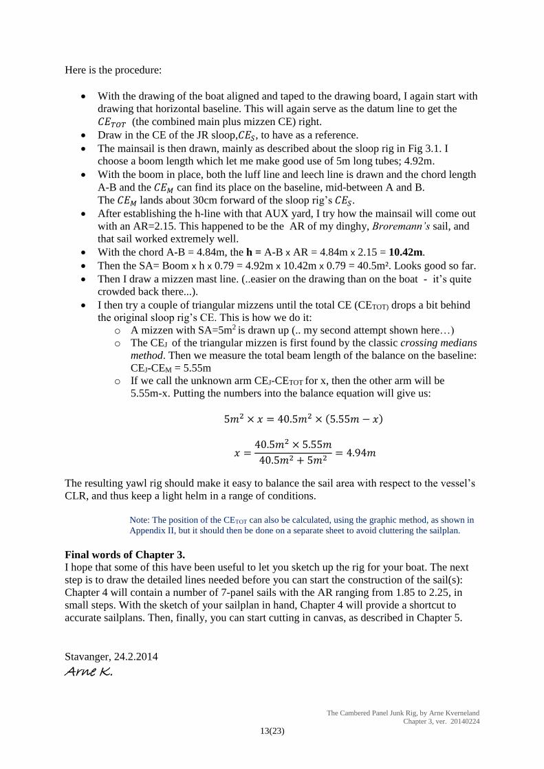
Here is the procedure:
With the drawing of the boat aligned and taped to the drawing board, I again start with
drawing that horizontal baseline. This will again serve as the datum line to get the
𝐶𝐸𝑇𝑂𝑇 (the combined main plus mizzen CE) right.
Draw in the CE of the JR sloop,𝐶𝐸𝑆, to have as a reference.
The mainsail is then drawn, mainly as described about the sloop rig in Fig 3.1. I
choose a boom length which let me make good use of 5m long tubes; 4.92m.
With the boom in place, both the luff line and leech line is drawn and the chord length
A-B and the 𝐶𝐸𝑀 can find its place on the baseline, mid-between A and B.
The 𝐶𝐸𝑀 lands about 30cm forward of the sloop rig’s 𝐶𝐸𝑆.
After establishing the h-line with that AUX yard, I try how the mainsail will come out
with an AR=2.15. This happened to be the AR of my dinghy, Broremann’s sail, and
that sail worked extremely well.
With the chord A-B = 4.84m, the h = A-B x AR = 4.84m x 2.15 = 10.42m.
Then the SA= Boom x h x 0.79 = 4.92m x 10.42m x 0.79 = 40.5m². Looks good so far.
Then I draw a mizzen mast line. (..easier on the drawing than on the boat - it’s quite
crowded back there...).
I then try a couple of triangular mizzens until the total CE (CETOT) drops a bit behind
the original sloop rig’s CE. This is how we do it:
o A mizzen with SA=5m2 is drawn up (.. my second attempt shown here…)
o The CEJ of the triangular mizzen is first found by the classic crossing medians
method. Then we measure the total beam length of the balance on the baseline:
CEJ-CEM = 5.55m
o If we call the unknown arm CEJ-CETOT for x, then the other arm will be
5.55m-x. Putting the numbers into the balance equation will give us:
5𝑚2 × 𝑥 = 40.5𝑚2 × (5.55𝑚 − 𝑥)
𝑥 =40.5𝑚2 × 5.55𝑚
40.5𝑚2 + 5𝑚2= 4.94𝑚
The resulting yawl rig should make it easy to balance the sail area with respect to the vessel’s
CLR, and thus keep a light helm in a range of conditions.
Note: The position of the CETOT can also be calculated, using the graphic method, as shown in
Appendix II, but it should then be done on a separate sheet to avoid cluttering the sailplan.
Final words of Chapter 3.
I hope that some of this have been useful to let you sketch up the rig for your boat. The next
step is to draw the detailed lines needed before you can start the construction of the sail(s):
Chapter 4 will contain a number of 7-panel sails with the AR ranging from 1.85 to 2.25, in
small steps. With the sketch of your sailplan in hand, Chapter 4 will provide a shortcut to
accurate sailplans. Then, finally, you can start cutting in canvas, as described in Chapter 5.
Stavanger, 24.2.2014
Arne K.
The Cambered Panel Junk Rig, by Arne Kverneland Chapter 3, ver. 20140224
14(23)
Appendix I, some full size diagrams
Fig 3.1, the sloop JR for a 26’ IF, two versions
The Cambered Panel Junk Rig, by Arne Kverneland Chapter 3, ver. 20140224
15(23)
Fig 3.2, Schooner with both sails at SA=40m2 and AR= 2.91
The Cambered Panel Junk Rig, by Arne Kverneland Chapter 3, ver. 20140224
16(23)
Fig 3.3, Schooner with both sails at SA=40m2 and AR= 2.26
The Cambered Panel Junk Rig, by Arne Kverneland Chapter 3, ver. 20140224
17(23)
Fig 3.4, schooner, SA = 53m2 + 40m2
The Cambered Panel Junk Rig, by Arne Kverneland Chapter 3, ver. 20140224
18(23)
Fig 3.5, yawl JR for Johanna, 40.5 + 5m2
The Cambered Panel Junk Rig, by Arne Kverneland Chapter 3, ver. 20140224
19(23)
Appendix II, a few notes on mathematics: (Most of you already know this, and more, but maybe a few of you may find it useful...)
There is no high-level maths involved in designing a Johanna style JR. Still, if your math
skills are really rusty, maybe this can be of some help:
Trigonometry:
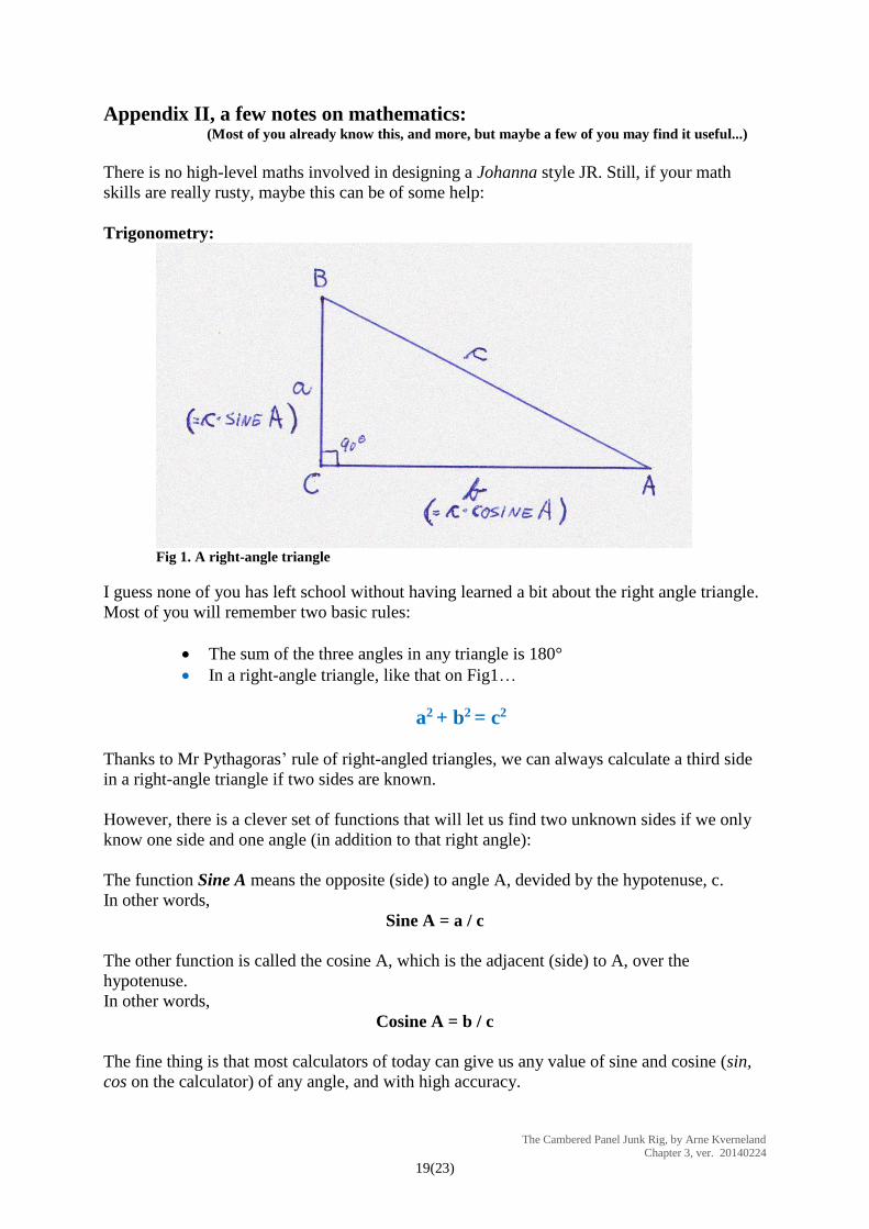
Fig 1. A right-angle triangle
I guess none of you has left school without having learned a bit about the right angle triangle.
Most of you will remember two basic rules:
The sum of the three angles in any triangle is 180°
In a right-angle triangle, like that on Fig1…
a2 + b2 = c2
Thanks to Mr Pythagoras’ rule of right-angled triangles, we can always calculate a third side
in a right-angle triangle if two sides are known.
However, there is a clever set of functions that will let us find two unknown sides if we only
know one side and one angle (in addition to that right angle):
The function Sine A means the opposite (side) to angle A, devided by the hypotenuse, c.
In other words,
Sine A = a / c
The other function is called the cosine A, which is the adjacent (side) to A, over the
hypotenuse.
In other words,
Cosine A = b / c
The fine thing is that most calculators of today can give us any value of sine and cosine (sin,
cos on the calculator) of any angle, and with high accuracy.
The Cambered Panel Junk Rig, by Arne Kverneland Chapter 3, ver. 20140224
20(23)
One example:
The angle at A= 27° and the hypotenuse, c= 5metre. How long are the short sides, a and b?
Answer: 𝑎 = 𝑐 × sin 𝐴 = 5𝑚 × sin 27° = 5𝑚 × 0.4540 = 2.270𝑚
and… 𝑏 = 𝑐 × 𝑐𝑜𝑠𝐴 = 5𝑚 × cos 27° = 5𝑚 × 0.8910 = 4.455𝑚
Note: Some of you will already have seen that if we look at the triangle from the angle B, then
Sine B = b / c
and
Cosine B = a / c
Comparing with the sine and cosine functions of the angle A, the conclusion is that
Sine A = Cosine B
and
Sine B = Cosine A
Another Example:
What if we only know the length of one short side, plus one of the angles of the right-angle
triangle? How can we find the other sides?
Let us say we know that a = 3metres and the angle at A = 28° (see Fig 1)
1. The procedure is to find the hypotenuse first:
Since Sine A = a / c, then c = a / Sine A
𝒄 =𝟑𝒎
𝑺𝒊𝒏𝟐𝟖°=
𝟑𝒎
𝟎. 𝟒𝟔𝟗𝟓= 𝟔. 𝟑𝟗𝒎
2. The next and last step is to find the length of side b, using the hypotenuse, c and the
cosine of the angle at A:
Then 𝐛 = 𝐜 × 𝐂𝐨𝐬𝐢𝐧𝐞 𝐀, in other words…
𝒃 = 𝟔. 𝟑𝟗𝒎 × 𝒄𝒐𝒔𝟐𝟖° = 𝟔. 𝟑𝟗𝒎 × 𝟎. 𝟖𝟖𝟐𝟗 = 𝟓. 𝟔𝟒𝒎
The Cambered Panel Junk Rig, by Arne Kverneland Chapter 3, ver. 20140224
21(23)
Now, let us try it on the sketch of a Johanna style sail:
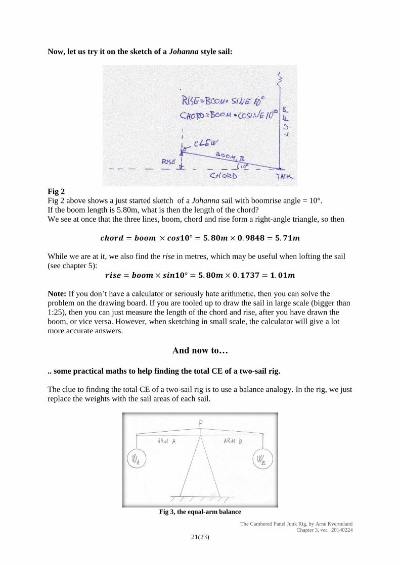
Fig 2
Fig 2 above shows a just started sketch of a Johanna sail with boomrise angle = 10°.
If the boom length is 5.80m, what is then the length of the chord?
We see at once that the three lines, boom, chord and rise form a right-angle triangle, so then
𝒄𝒉𝒐𝒓𝒅 = 𝒃𝒐𝒐𝒎 × 𝒄𝒐𝒔𝟏𝟎° = 𝟓. 𝟖𝟎𝒎 × 𝟎. 𝟗𝟖𝟒𝟖 = 𝟓. 𝟕𝟏𝒎
While we are at it, we also find the rise in metres, which may be useful when lofting the sail
(see chapter 5):
𝒓𝒊𝒔𝒆 = 𝒃𝒐𝒐𝒎 × 𝒔𝒊𝒏𝟏𝟎° = 𝟓. 𝟖𝟎𝒎 × 𝟎. 𝟏𝟕𝟑𝟕 = 𝟏. 𝟎𝟏𝒎
Note: If you don’t have a calculator or seriously hate arithmetic, then you can solve the
problem on the drawing board. If you are tooled up to draw the sail in large scale (bigger than
1:25), then you can just measure the length of the chord and rise, after you have drawn the
boom, or vice versa. However, when sketching in small scale, the calculator will give a lot
more accurate answers.
And now to…
.. some practical maths to help finding the total CE of a two-sail rig.
The clue to finding the total CE of a two-sail rig is to use a balance analogy. In the rig, we just
replace the weights with the sail areas of each sail.
Fig 3, the equal-arm balance
The Cambered Panel Junk Rig, by Arne Kverneland Chapter 3, ver. 20140224
22(23)
The balance with arms of equal length
Fig 3, above, shows the classic balance, as used for thousands of years. Both arms are of equal
length, so to achieve equilibrium, both weights, WA and WB, must be the same. Simple.
If we are lucky enough to be planning a two-sail rig with both sails of the same area, like
those shown in Fig 3.2 and Fig 3.3, then the principle of this equal-arm balance can be used:
The rig’s total CE will simply sit right in the middle between the CEs of each sail. To rub it
in, the rig will balance around this total CE (..called A in Fig 3.2 – 3.4…), just as the balance
above is balancing on the pivot point P.
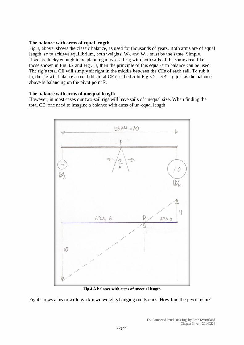
The balance with arms of unequal length
However, in most cases our two-sail rigs will have sails of unequal size. When finding the
total CE, one need to imagine a balance with arms of un-equal length.
Fig 4 A balance with arms of unequal length
Fig 4 shows a beam with two known weights hanging on its ends. How find the pivot point?
The Cambered Panel Junk Rig, by Arne Kverneland Chapter 3, ver. 20140224
23(23)
Grapic method
The classic way of finding the position of the balance point, P, is to do it graphically, as
shown in the lower part of Fig 4. In this example the total beam length is 10 and WA=4 and
WB=10.
The total beam is drawn up (in a rig, “the beam” is the line between the CEs of the
sails)
Then vertical lines with lengths analogue to the weights (or in the rig, sail areas) are
drawn up in opposite directions of each other. Note that the WA line is drawn at the
end of Arm B and vice versa.
Where the dotted line between the tip of each “weight-line” crosses the beam, the
balancing point, P (or total CE in the rig) will be.
Arithmetic method
The graphic method of finding the total CE has probably been in use since proper boat
designing started. It requires a fairly accurately made drawing. Nowadays, with a good
calculator at hand, and when drawing these fairly rough sketches (Fig 3.1 – 3.5), I personally
prefer to calculate the CE, using the simple Balance Equation:
𝐴𝑟𝑚 𝐴 × 𝑊𝐴 = 𝐴𝑟𝑚 𝐵 × 𝑊𝐵
Solving the case above would then look like this:
(Since the length of the beam is known, I cheat a little by first calculating 𝑨𝒓𝒎 𝑩 = 𝑩𝒆𝒂𝒎 − 𝑨𝒓𝒎 𝑨 )
With the unknown X here being Arm A,
then the balance equation for Fig 4 will be: 𝑊𝐴 × 𝑋 = 𝑊𝐵 × (𝐵𝑒𝑎𝑚 − 𝑋)
Inserting the numbers: 4𝑋 = 10(10 − 𝑋) = 100 − 10𝑋
4𝑋 + 10𝑋 = 100
𝑋 =100
4+10= 7.14 =Arm A
Then.. 𝐴𝑟𝑚 𝐵 = 10 − 7.14 = 2.86
This fits well with the graphic method, where I measured Arm A to be around 7.1 – 7.2. The
graphic method is not that accurate, but in most cases, it will do the job.
NOTE: Many thanks to Slieve McGalliard for helping with proof-reading, and for comments
and encouragement.