Embed Size (px)
Citation preview
IEEE TRANSACTIONS ON INDUSTRIAL ELECTRONICS AND CONTROL INSTRUMENTATION, VOL. IECI-20, NO. 1, FEBRUARY 1973 33
CONCLUSIONS The high sensitivity of boron thermistors also suggestsBoron thermistors have such characteristics to fore- an adequate use for these application purposes.
see new potential applications in the thermistors' field. Finally, the particular current-voltage character-M\leasurements of high temperatures have become possi- istics of boron thermistors suggest some circuits devotedble with high-level signal outputs, and a simple mathe- to perform particular tasks, such as the dc switch, thenmatical relationship, namely R=RO exp B/T, relates ac control circuit, protection from overheatings, andthe resistance R of the sensor to the measured tem- alarm.perature T. This fact is quite appreciable in control sys- ACKNOWLEDGMENTtems that make use of process computers. The authors wish to thank Prof. G. P. Bolognesi forWith the geometry presently chosen, the tempera- having called their attention to the boron properties
ture range of major interest appears to be 200-700°C. and for his helpful suggestions and advice, and Ing.For temperatures lower than 200°C, the high resistance G. F. Cirri for his technical assistance in designing andvalues and the change in the B constant are of some realizing the thermal probe. They also wish to ac-handicap. At a temperature higher than 700°C, the knowledge the encouragement and suggestion of allresistance of the sensors is very low and the connecting their colleagues and technicians at the Electronicwires in the measuring circuit affect the measurements. Laboratory.As previously discussed, the boron thermistors in this REFERENCES
temperature range show an acceptable interchange- [1] M. Prudenziati, A. Taroni, and G. Zanarini, "SemiconduCtorability and a very good stability when properly en- sensors: I-Thermoresistive devices," IEEE Trans. Ind. Elec-capsulated. tron. Contr. Instrum., vol. IECI-17, pp. 407-414, Nov. 1970.p [2] H. D. Batha and P. E. Carroll, "Unicrystalline silicon carbideThe present time constant of the encapsulated boron thermistor," IEEE Trans. Component Parts, vol. CP-1, pp. 129-
thermistors can be lowered by a more suitable encapsu- 134, June 1964.3]General Electric data sheet 6200.
lation technique. [4] American Institute of Physics, Temperature: Its MeasurementThe high value of the operating temperature of the and Control in Science and Industry. New York: Van Nostrand-The hig valueof theoperatig tempratureof the Reinhold, 1959.
boron thermistors also allows us to widen the applicabil- [5] G. K. Gaule, Ed., Boron: Preparation, Properties and Applica-ity of thermistors in applications concerning the mea- tions. New York: Plenum, 1965.
[61 M. Prudenziati, "Space charge limited current in beta-rhombo-surements of physical quantities such as flux, thermal hedral boron," Phys. Status Solidi, vol. 3, p. K81, 1970.conductivity, chemical composition, and level measure- [7] Thermistor Definition and Test Methods, EIA Standard RS 275.
[8] E. Weintraub, J. Ind. Eng. Chem., vol. 5, p. 106, 1913.ments. It is important to note that operations in gasses [9] F. W. Lyle, Phys. Rev., vol. 11, p. 253, 1918.and liquids at temperatures previously forbidden are [10] J. H. Bruce and A. Hickling, Trans. Faraday Soc., vol. 35,
p. 1436, 1939now possible. [11] W. Klein, J. Appl. Phys., vol. 39, p. 5797, 1968.
Chopper Circuits ror Direct AC/DC ConversionPARESH C. SEN AND STEPHEN E. MCCONKEY
Abstract-The feasibility of using chopper circuits in ac supply to I. NOMENCLATUREprovide variable dc output is investigated. The three basic choppercircuits are considered and their input and output characteristics are e Instantaneous ac input voltage = Em sin cut.thoroughly studied for direct ac/dc conversion. The performances eL Instantaneous output voltage.of these ac-fed choppers for two types of control, time-ratio control EL Average output voltage.(TRC) and phase-shift control (PSC), are compared. One chopper j1 Instantaneous inductor current.circuit is found to provide better performance characteristics thanthe other two choppers. The three ac-fed choppers are tested on i2 Instantaneous load current.experimental models to verfy theoretical predictions. Io Value of i1 at t = to.
120 Value of i2att=to.Manuscript received May 8, 1972. '2Zr Value of i2 at t =tIz.P. C. Senl is with the Department of Electrica(l Engineering>, J,, RNIS value of nthl harmonic in inpult culrrent.
Queen's University, Kingston, Out., Canada...S.E. McConkey was with the Department of Electrical Engineer- lt Initial valule of time I.
ing, Queen's University, Kingston, Ont., Canada. He is now with 1g Value of timne l when i1 becomes zero.the Bell-Canada-Northern-Electric Research Company, Lachine, T0 OnproofsvthQue., Canada. Tn O eldo wth
34 IEEE TRANSACTIONS ON INDUSTRIAL ELECTRONICS AND CONTROL INSTRUMENTATION, FEBRUARY 1973
T0ff Off period of switch. Variable DC Output
Ooff Value of ad at end of TOD. ILnput DC Source Input AC Source
D Differential operator d/dt.a(1/2RC). MG Set Solid State Converter MG Set Solid State Converter
b = ((1/LC) - (1/4R2C2))"2I02 = tan-1 (a/b). Inverter/Rectifier Chopper Controlled 'Chopper.
Rectifier - -
G1 =w-02.Fig. 1. Methods for obtaining variable dc output.
I . INTRODUCTION
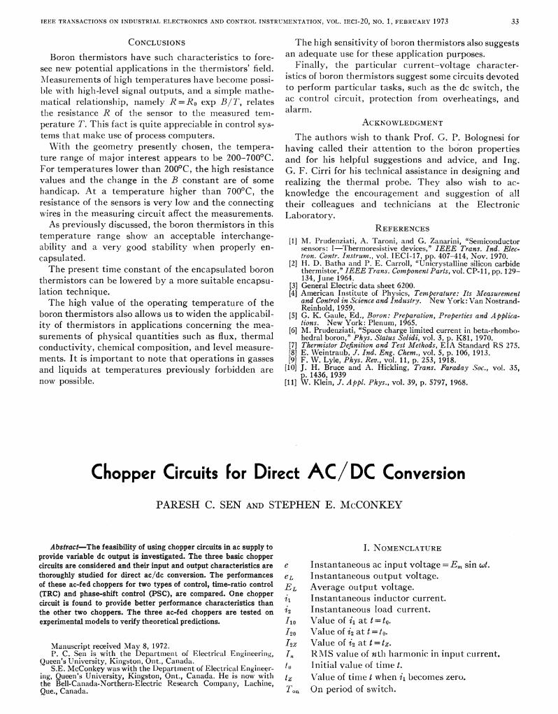
Tp/ HERE ARE many applications that require a i2variable dc supply. The method of obtaining this + +supply varies with the type of application and the e e
main supply (ac or dc) that is available. Fig. 1 illustrates e eLthese different methods. The techniques used to obtain ,, _ l _l_ Ivariable dc from a main dc supply are different fromthose required to provide variable dc from a main ac Circuit lsupply.
A. DC-to-DC ConversionThe classical method of dc-to-dc conversion involves
the use of a motor-generator (MG) set with voltage con- e etrol on the generator. Solid-state converters began to ___
displace 1\G sets as high-power semiconductor devices - _ _ X +
became commercially available. These static converters Circuit 2proved to be efficient, less expensive, and could run forlonger periods with practically no maintenance.Two basic types of static converters were developed.
The first type involves dc-to-dc conversion with an ac + i
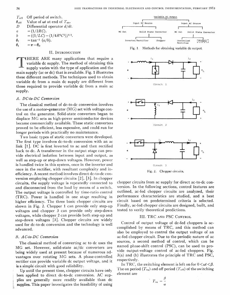
link [1]. DC is first inverted to ac and then rectified Iback to dc. A transformer in the output stage can pro- e eLvide electrical isolation between input and output, as Tvell as step-up or step-down voltages. However, power -is handled twice in this system, once in the inverter and Circuit 3once in the rectifier, with resultant complexitv and in- Fig. 2. Chopper cirCuitS.efficiency. A recent method involves direct dc-to-dc con-version employing chopper circuits [2], [3]. In choppercircuits, the supply voltage is repeatedly connected to chopper circuits from ac supply for direct ac-to-dc con-and disconnected from the load by means of a switch. version. In the following sections, control features areThe output voltage is controlled by time-ratio control outlined, ac-fed chopper circuits are analyzed, their(TRC). Power is handled in one stage resulting in performance characteristics are studied, and a besthigher efficiency. The three basic chopper circuits are circuit based on predetermined criteria is selected.shown in Fig. 2. Chopper 1 can provide only step-up Finally, ac-fed chopper circuits are designed, built, andvoltages and chopper 3 can provide only step-down tested to verify theoretical predictions.voltages, while chopper 2 can provide both step-up and Ill. TRC AND PSC CONTROLstep-down voltages [3]. Chopper circuits are widelyused for dc-to-dc conversion and the technology is well Control of output voltage of dc-fed choppers is ac-
advanced, ~~~~~~~complished by means of TRC, and this method canadvanced.also be employed to control the output voltage of an
B. AC-to-DC Conversion ac-fed chopper circuit. Due to the periodic nature of ac
The classical method of converting ac to dc uses the sources, a second method of control, which can beMG set. However, solid-state ac/dc converters are named phase-shift control (PSC), can be used to pro-being widely used at present because of numerous ad- vide output-voltage control of ac-fed choppers. Fig.vantages over rotating1"4IG sets. A phase-controlled 3(a) and (b) illustrates the principle of TRC and PSC,rectifier can provide variable dc outpult voltage, and it respectively.is a simple circuit withl good reliability. Inl TRC, the switchinlg elemenlt is left on for 0 <o.t <p3.Up until the present time, chopper circuits have only Th1e onl period (Ton) and off period (Toff) of the switchinlg
been applied to direct dc-to-dc conversion. AC sup element areplies are generally more readily available than dc T01 = $supplies. This paper investigates the feasibility of usingX
SEN AND MCCONKEY: CHlOPPEIRS FOR AC/DC CONVERSION 35
\>st 3 I~ ~ ~ ~~~~~~~~~~~~~~~~~loth
(a)~~~~~~~~~~~~~~~~~~+
| ;\ - L _t -B (b)
(b) L R_Fig. 3. Basic prinlciples of TRC and PSC. (a) TRC. (b) PSC.e (c
2rrCD
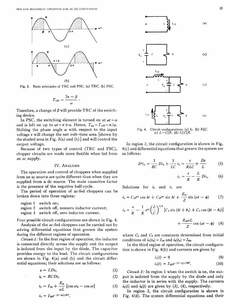
Therefore, a change of Ai will provide TRC of the switch- +ing device. Il L E-C< R(d)
In PSC, the switching element is turned on at wi =o 1and is left on up to cot =±+at. Hence, Ton= T0ff=7/w.Shifting the phase angle a with respect to the input Fi.4 (icuiLcniguaions (a)L. (b) RICvoltage e will change the net volt-time area [shown by ()LCj.()LJCRthe shaded area in Fig. 3(a) and (b) ] and will control theoutput voltage. In region 2, the circuit configuration is shown in Fig.Because of two types of control (TRC and PSC), 4(c) and differential equations that govern the system are
chopper circuits are made more flexible when fed from as follows:an ac supply. 11e D
IV. ANALYSIS D2i1-=---Di+--Cii= eL +c (5
The operation and control of choppers when supplied e Lfrom an ac source are quite different than when they are i2 =R---R-Di1. (6)supplied from a dc source. The main causative factorR Ris the presence of the negative half-cycle. Solutions for i1 and i2 areThe period of operation of ac-fed choppers can be Em
broken down into three regions: i1 = Cieat cos bit + C2eai sin bi +-- sin (cot - ) (7)
region 1 switch on;region 2 switch off, nonzero inductor current; i= e - ± eat (LyIA [C, sin (bti + 0l) + C2 cos (bit- 2)1]region 3 switch off, zero inductor current. R R \C/
Four possible circuit configurations are shown in Fig. 4. Em¢OLAnalysis of the ac-fed choppers can be carried out by +-cszt+ 8
solving differential equations that govern the systemduring the different regions of operation. where C1 and C2 are constants determined from initial
Circuit 1: In the first region of operation, the inductor conditions of i1(to) =I o and i2(to) =I20.is connected directly across the supply and the output In the third region of operation, the circuit configura-is isolated from the input by the diode. The capacitor tion is shown in Fig. 4(b) and currents are given byprovides energy to the load. The circuit configurationsare shown in Fig. 4(a) and (b) and the circuit differ- ii(t) = 0 (9)ential equations; their solutions are as follows: i2(t) =I2ze-~(t-tz)RC. (10)
c = LDi1 (1) Circuit 2: In region 1 when the switch is on, the out-
i2= RCDi2 (2) put is isolated from the supply by the diode and only
Em the inductor is in series with the supply. The currentsil= 110 +-[cos ct0 -cos ct] (3) ii(t) and i2(t) are given by (3), (4), respectively.
XoL In region 2, the circuit configuration is shown ini2I2oe (tto)IRQ (4) Fig. 4(d). The system differential equations and their
36 IEEETrRANSACTIONS ON INDUSi'TRIAI, ELECTRONICS ANI) CONTROL INS'TRU'MENTATION, FEBRUARY 1973
L = 0.01 H
R = 5 ohms
0.8Circuit 2
E o.6
0.4 _ _ _
0.2 _/
/N.Circuit 1
0.00 90 180 270 360
B (degrees)
1F-ig. 5. TRC output characteristics.
0.8 L = 0.01 HR = 5 ohms
o.6EL
Em
0.4
\N\\ /e . - Circuit 1
0.2 N 0fiCircuit 2
Circuit 3
0.00 90 180 270 360
a (degrees)
Fig. 6. PSC output characteristics.
L = 0.01 H
0.6 R = 5 ohms
/ i ~~~~~Circuit 3
0.5
| / //\ \ ~~~~~~~~~~~Circuit20.4
04 0.34.
Circuit 1
0.0 /
0 90 180 270 3608 (degrees )
Fig. 7. Input power factor (TRC).
SEN ANI) MCCONKEY: CHOPPERS FOR AC/DC CONVERSION 37
L = 0.01 H
R = 5 ohms
0.5 *_ Circuit 3
\\ Circuit 1
o.b4
o 0.33 Circuit 2 /
D., 0.2 _,
0.1
0.0
0 90 180 270 360
a (degrees)
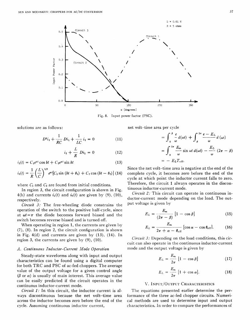
Fig. 8. Input power factor (PSC).
solutions are as follows: net volt-time area per cycle
1 1 ~ ~ ~~~~~~~~~~~~~~e(2wr e -ELd(c)D2il+--Di, +--i= O (11) w- d + j
RC LC ,L ~~~ ~ ~ ~ ~ ~ ~ -~~~~~~'--Edtn -EL
i2 + - Dii =0 (12) J -sin wt d(t) (27r
ii(t) = Cieat cos bt + C2eat sin bt (13) = -ELTOff.
1 L 1/2 Since the net volt-time area is negative at the end of thei2(t) = R(-) eat [C, sin (bt + 01) + C2 cos (bt- 02)] (14) complete cycle, it becomes zero before the end of the
C\L/ cycle at which point the inductor current falls to zero.
where C1 and C2 are found from initial conditions. Therefore, the circuit 1 always operates in the discon-In region 3, the circuit configuration is shown in Fig. tinuous inductor-current mode.
4(b) and currents i1(t) and i2(t) are given by (9), (10), Circuit 2: This circuit can operate in continuous in-respectively. ductor-current mode depending on the load. The out-
Circuit 3: The free-wheeling diode constrains the put voltage is given byoperation of the switch to the positive half-cycle, since Emat wt= r the diode becomes forward biased and the EL = [1 -COS3 (15)switch becomes reverse biased and is turned off. (27 - f)When operating in region 1, the currents are given by EL,=Em
(7), (8). In region 2, the circuit configuration is shown 2 + a a offin Fig. 4(d) and currents are given by (13), (14). In ....region 3, the currents are given by (9), (10) . Circulit 3: Depending on the load conditions, this cir-
cuit can also operate in the continuous inductor-currentA. Continuous Inductor-Current Mode Operation mode and the output voltage is given by
Steady-state waveforms along with input and output Em[,characteristics can be found using a digital computer EL = Lir - COS (17)for both TRC and PSC of ac-fed choppers. The average Evalue of the output voltage for a given control angle EL = -- [1 + cos a]. (18)(f or a) is usually of main interest. This average value 2 rcan be easily predicted if the circuit operates in thecontinuous inductor-current mode.V.IPTOTUCHRTESIS
Circuit 1: In this circuit, the inductor current is al- The equations presented earlier determine the per-ways discontinuous because the net volt-time area formance of the three ac-fed chopper circulits. Numeri-across the inductor becomes zero before the end of the cal methods are used to determine input and outputcycle. Assuming continuous inductor current, chlaracteristics. In order to compare thle performances of
38 IEEEIR'ANSACTIONS ON INDUSTRIAL, ELECTRONICS AND CONTROL, INSTRUMENTATION, FEBRUARY 1973
3.0L = 0.01 H
3.0 I_ \ iI
- Circuit 1
Circuit 2
Circuit 3
ii ~ ~ \2.0 4
., 1. O0IDC/ _
IDC/l
0.0 I I I I0 90 180 270 360
H (degrees)
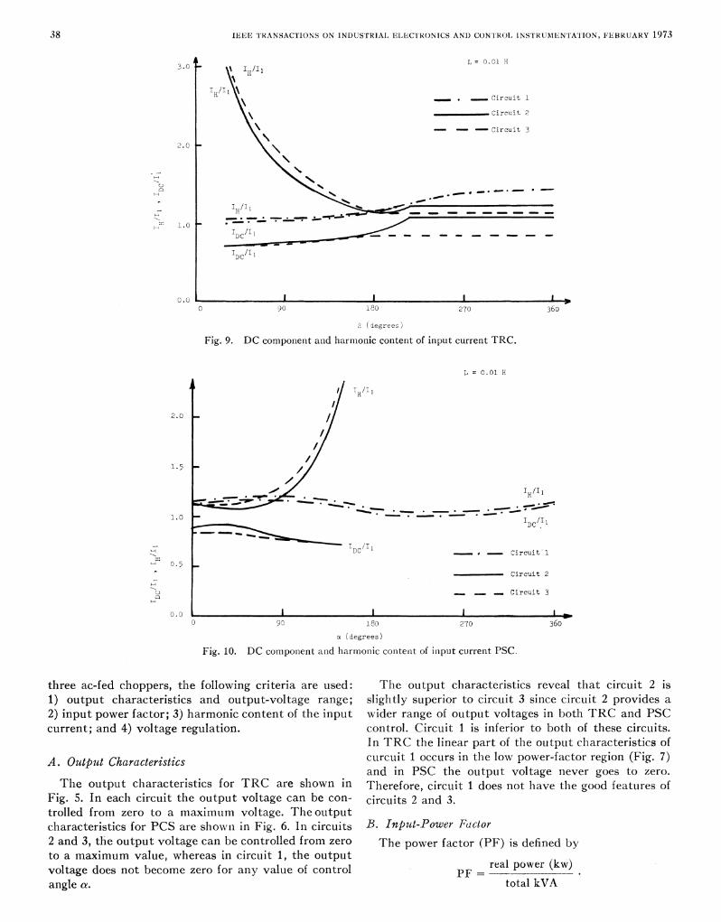
Fig. 9. DC component and harmonic content of input current TRC.
L = 0.01 H
H
2.0 _/
//1.5
HI /I
DC/I Circuit
0.5
Circuit 2
'i - -_Circuit 3
0.00 90 180 270 360
a (degrees)
Fig. 10. DC component and harmonic contenit of input current PSC.
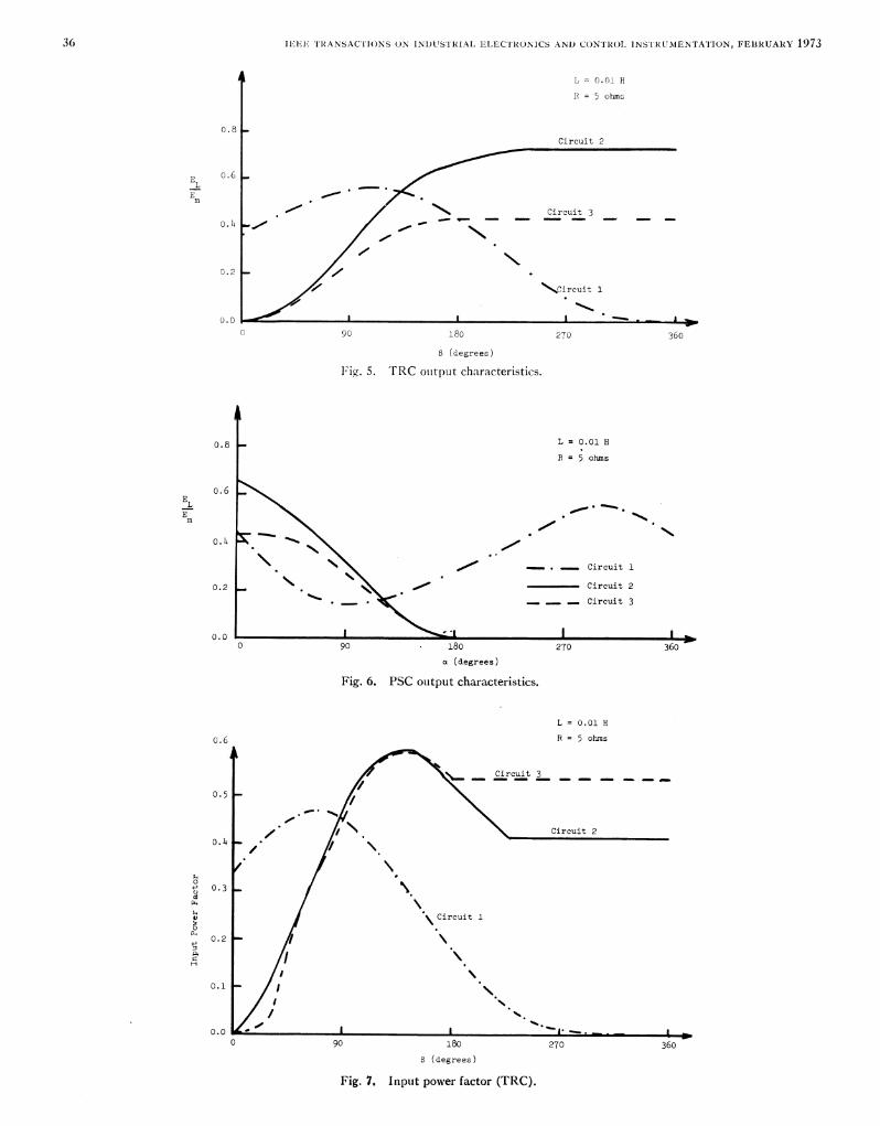
three ac-fed choppers, the following criteria are used: The output characteristics reveal that circuit 2 is1) output characteristics and output-voltage range; slightly superior to circuit 3 since circuit 2 provides a2) input power factor; 3) harmonic content of the input wider range of output voltages in both TRC and PSCcurrent; and 4) voltage regulation. control. Circuit 1 is inferior to both of these circuits.
In TRC the linear part of the output characteristics of
A. Output Characteristics curcuit 1 occurs in the low power-factor region (Fig. 7)and in PSC the output voltage never goes to zero.
The output characteristics for TRC are shown in Therefore, circuit 1 does not have the good features ofFig. 5. In each circuit the output voltage can be con- circuits 2 and 3.trolled from zero to a maximum voltage. Theoutputcharacteristics for PCS are shownl in Fig. 6. In circuits B. Input-Power Factor2 and 3, thie output voltage can be controlled from zero The power factor (PF) is defined byto a maximum value, whereas in circuit 1, the outputralpwr()voltage does not become zero for any value of control PF =elpwr(wangle a. total kVA
SEN AND MCCONKEY: CHOPPERS FOR AC/DC CONVERSION 39
F = 1500
1.0
0.8 \
Circuit 2
Continuous Inductor Current _
O.~~~~%094\X _ ~~~~~~~~~~~~~Cirscuit3
Continuous Inductor Current0.2
Circuit1
0.0 I --SC 4.0 8.o 12.0 16.0
Load Current ( Aps)
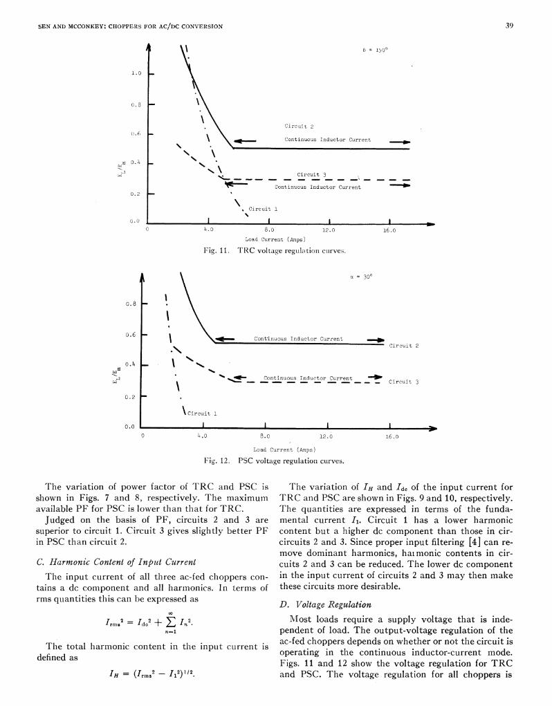
Fig. 11. TRC voltage reguLlation cuirves.
0.8
o.6 l_____ Cont'inuous Inductor Current
Circuit 2
0.4
0.2 ~ Continuous Inductor Current Ccrw _ _ s uc u en ~~~~~~~~~~~~~~~~Circu-it3
0.2_
\ Circuit 1
0.0 I I I I0 4.0 8.o 12.0 16.0
Load Current (Amps)
Fi,g. 12. PSC voltage regulation curves.
The variation of power factor of TRC and PSC is The variation of IH and 'dc of the input current forshown in Figs. 7 and 8, respectively. The maximum TRC and PSC are shown in Figs. 9 and 10, respectively.available PF for PSC is lower than that for TRC. The quantities are expressed in terms of the funda-Judged on the basis of PF, circuits 2 and 3 are mental current A1. Circuit 1 has a lower harmonic
superior to circuit 1. Circuit 3 gives slightly better PF content but a higher dc component than those in cir-in PSC than circuit 2. circuits 2 and 3. Since proper input filtering [4] can re-
move dominant harmonics, haimonic contents in cir-C. Harmonic Content of Input Current cuits 2 and 3 can be reduced. The lower dc componentThe input current of all three ac-fed choppers con- in the input current of circuits 2 and 3 may then make
tains a dc component and all harmonics. In terms of these circuits more desirable.rms quantities this can be expressed as D. Voltage Regulation
IrmW2 =d2 + EIc2. Most loads require a supply voltage that is inde-n3l ~~~~~pendent of load. The output-voltage regulation of the
The otalharoniccontnt n th inpt crren isac-fed choppers depends on whether or not the circuit isoperating in the continuous inductor-current mode.defined as Figs. 11 and 12 show the voltage regulation for TRC
IH = (Irmz2 _ Il2)1/2. and P>SC. The voltage regulation for all choppers is
40 IEEE TRANSACTIONS ON INDUSTRIAL ELECTRONICS AND CONTROL INSTRUMENTATION, FEBRUARY 1973
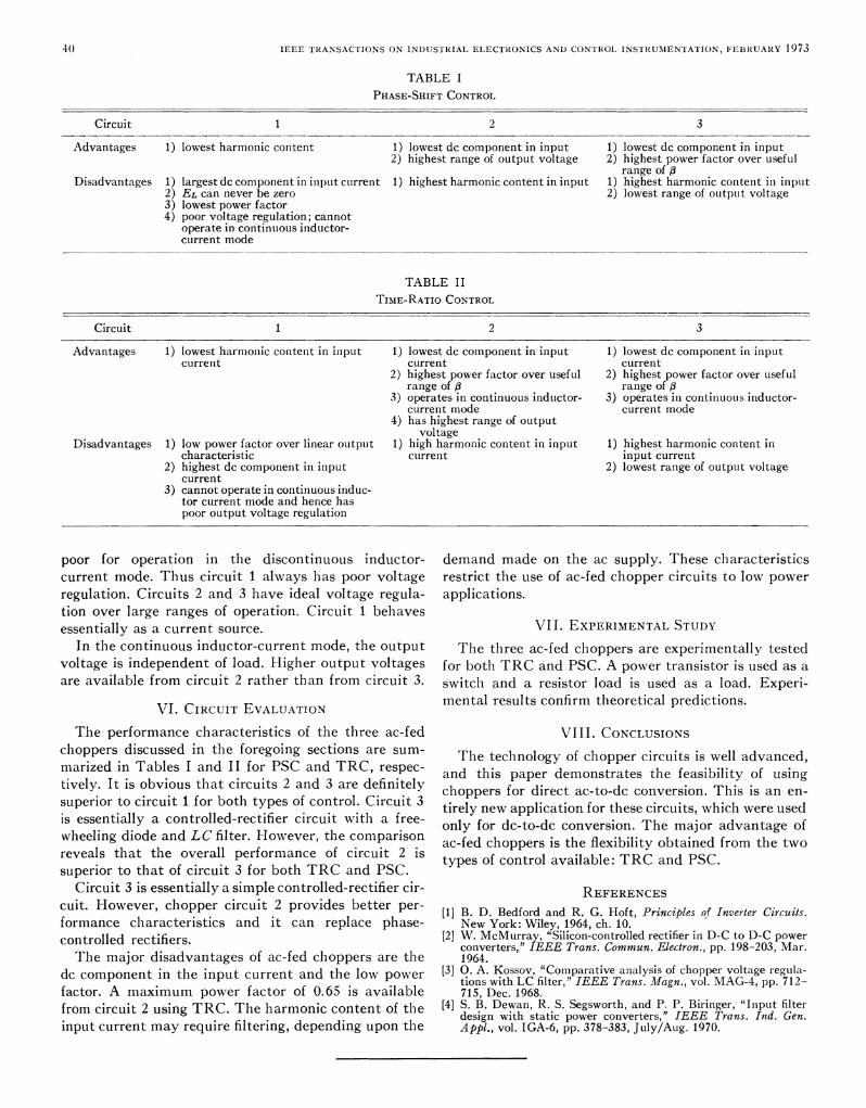
TABLE IPHASE-SHIFT CONTROL
Circuit 1 2 3
Advantages 1) lowest harmonic content 1) lowest dc component in input 1) lowest dc component in input2) highest range of output voltage 2) highest power factor over useful
range of /3Disadvantages 1) largest dc component in inplut cLrren-t 1) highest harmonic content in input 1) highest harmonic contenit in input
2) EL can never be zero 2) lowest range of outpuit voltage3) lowest power factor4) poor voltage regulation; cannot
operate in continuous inductor-current mode
TABLE IITIME-RATIO CONTROL
Circuit 1 2 3
Advantages 1) lowest harmonic content in input 1) lowest dc component in input 1) lowest dc component in inputcurrent current current
2) highest power factor over useful 2) highest power factor over usefulrange of /3 range of /3
3) operates in continuous inductor- 3) operates in continuous inductor-current mode current mode
4) has highest range of outputvoltage
Disadvantages 1) low power factor over linear Outptlt 1) high harmonic content in input 1) highest harmonic content incharacteristic current input current
2) highest dc component in input 2) lowest range of output voltagecurrent
3) cannot operate in continuous induc-tor current mode and hence haspoor output voltage regulation
poor for operation in the discontinuous inductor- demand made on the ac supply. These characteristicscurrent mode. Thus circuit 1 always has poor voltage restrict the use of ac-fed chopper circuits to low powerregulation. Circuits 2 and 3 have ideal voltage regula- applications.tion over large ranges of operation. Circuit 1 behavesessentially as a current source. VII. EXPERIMENTAL STUDY
In the continuous inductor-current mode, the output The three ac-fed choppers are experimentally testedvoltage is independent of load. Higher output voltages for both TRC and PSC. A power transistor is used as aare available from circuit 2 rather than from circuit 3. switch and a resistor load is used as a load. Experi-
VI. CIRCUIT EVALUATION mental results confirm theoretical predictions.
The performance characteristics of the three ac-fed VIII. CONCLUSIONSchoppers discussed in the foregoing sections are sum- The technology of chopper circuits is well advanced,marized in Tables I and II for PSC and TRC, respec- and this paper demonstrates the feasibility of usingtively. It is obvious that circuits 2 and 3 are definitely choppers for direct ac-to-dc conversion. This is an en-superior to circuit 1 for both types of control. Circuit 3 tirely new application for these circuits, which were usedis essentially a controlled-rectifier circuit with a free- only for dc-to-dc conversion. The major advantage ofwheeling diode and LC filter. However, the comparison ac-fed choppers is the flexibility obtained from the tworeveals that the overall performance of circuit 2 is types of control available: TRC and PSC.superior to that of circuit 3 for both TRC and PSC.
Circuit 3 is essentially a simple controlled-rectifier cir- REFERENCEScuit. However, chopper circuit 2 provides better per- [1] B. D. Bedford and R. G. Hoft, Principles of Inverter Circuits.formance characteristics and it can replace phase- New York: Wiley, 1964, ch. 10.controlled rectifiers. [2] W. McMurray, "Silicon-controlled rectifier in D-C to D-C power
converters," IEEE Trans. Commun. Electron., pp. 198-203, Mar.The major disadvantages of ac-fed choppers are the 1964.
dc component in the input current and the low power [3] 0. A. Kossov, "Comparative analysis of chopper voltage regula-tions with LC filter," IEEE Trans. Magn., vol. MAG-4, pp. 712-factor. A maximum power factor of 0.65 is available 715, Dec. 1968.from circuit 2 using TRC. The harmonic content of the [4] 5. B. Dewan, R. S. Segsworth, and P. P. Biringer, "Input filterdesign with static power converters," IEEE Trans. Ind. Gen.input current may require filtering, depending upon the Appl., vol. IGA-6, pp. 378-383, July/Aug. 1970.