Embed Size (px)
DESCRIPTION
hhhhhhhhhhhhhhhhhhhhhhhhhhhhhhhhhhhhh
Citation preview
Chapter 1. PEM Fuel Cell Model Theory
This chapter presents the theoretical background for the PEM fuel cell modeling capa-bilities in FLUENT.
• Section 1.1: Introduction
• Section 1.2: Electrochemistry Modeling
• Section 1.3: Current and Mass Conservation
• Section 1.4: Liquid Water Formation, Transport, and its Effects
• Section 1.5: Properties
• Section 1.6: Transient Simulation of PEM Fuel Cells
1.1 Introduction
The PEM Fuel Cell (PEMFC) module is provided as an addon module with the standardFLUENT licensed software. A special license is required to use the PEMFC module.
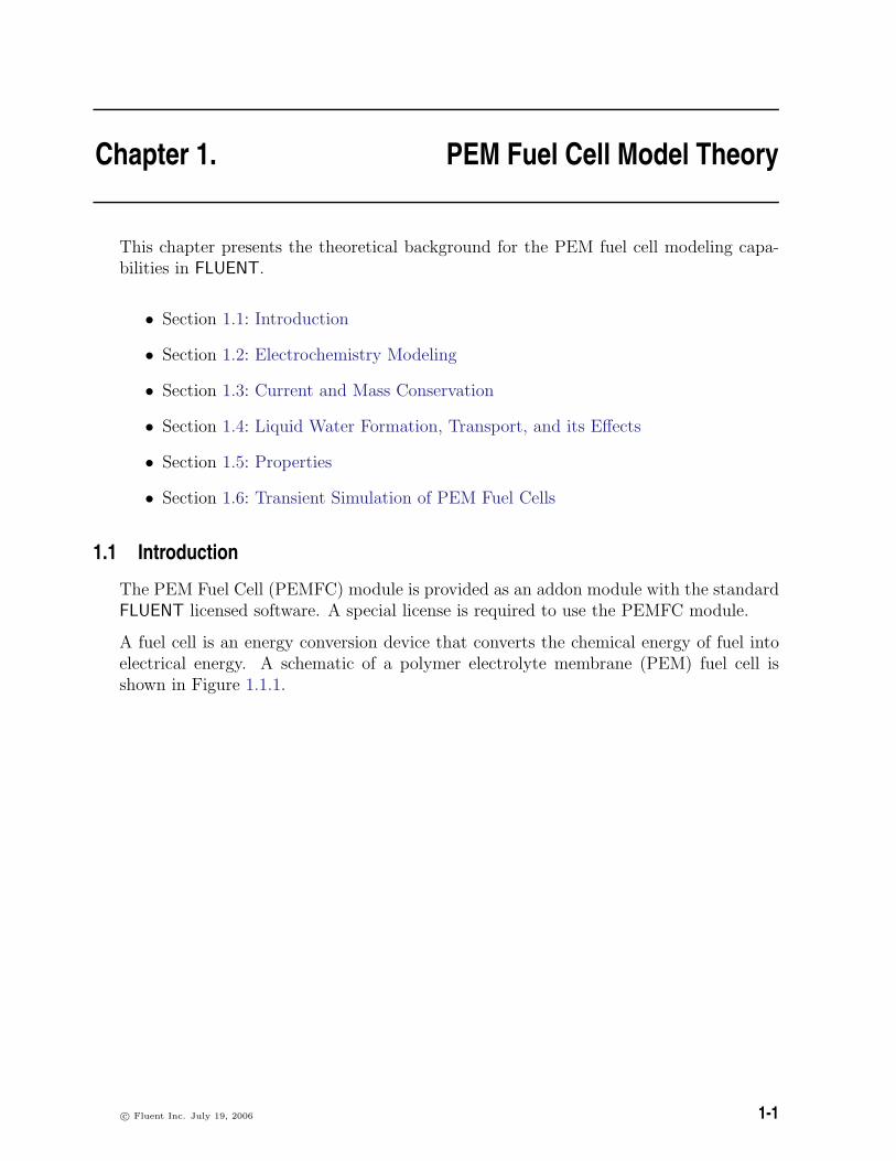
A fuel cell is an energy conversion device that converts the chemical energy of fuel intoelectrical energy. A schematic of a polymer electrolyte membrane (PEM) fuel cell isshown in Figure 1.1.1.
c© Fluent Inc. July 19, 2006 1-1
PEM Fuel Cell Model Theory
����������������������������������������������������������������������������������������������������������������������������������������������������������������������������
����������������������������������������������������������������������������������������������������������������������������������������������������������������������������
O + 4H + 4e −2 22H O+
−+ 4H + 4e 22H
Cooling Channel(s)
Cathode Collector
Cathode Gas Diffusion Layer
Cathode Catalyst Layer
Anode Catalyst Layer
Anode Gas Diffusion Layer
Anode CollectorCooling Channel(s)
e −
�����������������������������������������������������������������������������������������������������������������������������������������������������������������������������������������������������������������������
�����������������������������������������������������������������������������������������������������������������������������������������������������������������������������������������������������������������������
load+ +H H
2Gas Channel (H )
Gas Channel (air)
Electrolyte Membrane
Figure 1.1.1: Schematic of a PEM Fuel Cell
Hydrogen flows into the fuel cell on the anode side. It diffuses through the porous gasdiffusion layers and comes in contact with the catalyst layer. Here it forms hydrogenions and electrons. The hydrogen ions diffuse through the polymer electrolyte membraneat the center, the electrons flow through the gas diffusion layer to the current collectorsand into the electric load attached. Electrons enter the cathode side through the currentcollectors and the gas diffusion layer. At the catalyst layer on the cathode side, theelectrons, the hydrogen ions and the oxygen combine to form water.
In the PEM fuel cell model in FLUENT, two electric potential fields are solved. Onepotential is solved in the membrane and catalyst layers. The other is solved in thecatalyst layers, the diffusion layers, and the current collectors. Surface reactions onthe porous catalyst region are solved and the reaction diffusion balance is applied tocompute the rates. Based on the cell voltage that you prescribe, the current densityvalue is computed. Alternatively, a cell voltage can be computed based on a prescribedaverage current density.
1-2 c© Fluent Inc. July 19, 2006

1.2 Electrochemistry Modeling
1.2 Electrochemistry Modeling
At the center of the electrochemistry is the computation of the rate of the hydrogenoxidation and the rate of oxygen reduction. In the FLUENT PEM model, these electro-chemical processes are treated as heterogeneous reactions that take place on the catalystsurfaces inside the two catalyst layers on both sides of the membrane. Such detailedtreatment has been used by other groups ([1], [2], and [8]).
The driving force behind these reactions is the surface over-potential: the difference be-tween the phase potential of the solid and the phase potential of the electrolyte/membrane.Therefore, two potential equations are solved for in the PEM model: one potential equa-tion (Equations 1.2-1) accounts for the electron transport e− through the solid conductivematerials (i.e., the current collectors and solid grids of the porous media); the other po-tential equation (1.2-2) represents the protonic (i.e., ionic) transport of H+ . The twopotential equations read,
∇ · (σsol∇φsol) +Rsol = 0 (1.2-1)
∇ · (σmem∇φmem) +Rmem = 0 (1.2-2)
where
σ = electrical conductivity (1/ohm-m)φ = electric potential (volts)R = volumetric transfer current (A/m3)
The following figure illustrates the boundary conditions that are used to solve for φsol
and φmem.
There are two types of external boundaries. Those through which there passes an elec-trical current and those through which there passes no current.
As no protonic current leaves the fuel cell through any external boundary, there is azero flux boundary condition for the membrane phase potential, φmem, on all outsideboundaries.
For the solid phase potential, φsol, there are external boundaries on the anode and thecathode side that are in contact with the external electric circuit and only through theseboundaries passes the electrical current generated in the fuel cell. On all other externalboundaries there is a zero flux boundary condition for φsol.
On the external contact boundaries, we recommend to prescribe fixed values for φsol
(potentiostatic boundary conditions). If the anode side is set to zero, the (positive) valueprescribed on the cathode side is the cell voltage. Specifying a constant flux (say on thecathode side) means to specify galvanostatic boundary conditions.
c© Fluent Inc. July 19, 2006 1-3

PEM Fuel Cell Model Theory
�
�
�
�
��
?
6
-�
Cathode Catalyst Layer
Cooling Channel(s)
Anode Collector
Anode Gas Diffusion Layer
Anode Catalyst Layer
Cathode Gas Diffusion Layer
Cathode Collector
Cooling Channel(s)
2H2 −→ 4H+ + 4e−
φsol = 0
φsol = Vcell or ∂φsol∂n
= constant
∂φmem∂n
= 0∂φsol∂n
= 0
∂φmem∂n
= 0
∂φmem∂n
= 0
∂φmem∂n
= 0∂φsol∂n
= 0
O2 + 4H+ + 4e− −→ 2H2O
? ?
�
+ +H H
�
Gas Channel (air)
Electrolyte Membrane
Gas Channel (H2)
Figure 1.2.1: Boundary Conditions for φsol and φmem
The transfer currents, or the source terms in Equations 1.2-1 and 1.2-2, are non-zero onlyinside the catalyst layers and are computed as:
• For the solid phase, Rsol = −Ran(< 0) on the anode side and Rsol = +Rcat(> 0) onthe cathode side.
• For the membrane phase, Rmem = +Ran(> 0) on the anode side and Rmem =−Rcat(< 0) on the cathode side.
The source terms in Equations 1.2-1 and 1.2-2 are also called the exchange current density(A/m3), and have the following general definitions:
Ran = jrefan
([H2]
[H2]ref
)γan (eαanFηan/RT − e−αcatFηan/RT
)(1.2-3)
Rcat = jrefcat
([O2]
[O2]ref
)γcat (−e+αanFηcat/RT + e−αcatFηcat/RT
)(1.2-4)
1-4 c© Fluent Inc. July 19, 2006

1.2 Electrochemistry Modeling
where
jref = volumetric reference exchange current density (A/m3)[ ],[ ]ref = local species concentration, reference value (kgmol/m3)γ = concentration dependence (dimensionless)α = transfer coefficient (dimensionless)F = Faraday constant (9.65× 10⁷ C/kgmol)
The above equation is the general formulation of the Butler-Volmer function. A simpli-fication to this is the Tafel formulation that reads,
Ran = jrefan
([H2]
[H2]ref
)γan (eαanFηan/RT
)(1.2-5)
Rcat = jrefcat
([O2]
[O2]ref
)γcat (e−αcatFηcat/RT
)(1.2-6)
By default, the Butler-Volmer function is used in the FLUENT PEM model to computethe transfer currents inside the catalyst layers.
The driving force for the kinetics is the local surface over-potential, η, also known as theactivation loss. It is generally the difference between the solid and membrane potentials,φsol and φmem.
The gain in electrical potential from crossing from the anode to the cathode side canthen be taken into account by subtracting the open-circuit voltage Voc on the cathodeside.
ηan = φsol − φmem (1.2-7)
ηcat = φsol − φmem − Voc (1.2-8)
From Equations 1.2-1 through 1.2-8, the two potential fields can be obtained.
c© Fluent Inc. July 19, 2006 1-5

PEM Fuel Cell Model Theory
1.3 Current and Mass Conservation
The following reactions occur, respectively, at the anode and the cathode:
H2 −→ 2H+ + 2e−
O2 + 4H+ + 4e− −→ 2H2O
The volumetric source terms for the species equations (kg/m3-s) and energy equation(W/m3) are given in Equations 1.3-1–1.3-4.
SH2 = −Mw,H2
2FRan (1.3-1)
SO2 = −Mw,O2
4FRcat (1.3-2)
SH20 =Mw,H20
2FRcat (1.3-3)
Additional volumetric sources to the energy equation implemented in the FLUENT PEMmodel include ohmic heating, heat of formation of water, electric work and latent heatof water.
Sh = I2Rohm + hreaction + ηRan,cat + hphase (1.3-4)
The electrochemical reactions that take place inside the catalyst layers are consideredheterogeneous reactions that take place on the catalyst surfaces in the porous media.Therefore, the species concentrations of hydrogen and oxygen in the rate calculation,Equations 1.2-3 and 1.2-6, are the surface values. The reactions are treated as surfacereactions in the two catalyst layers, and it is assumed that the diffusive flux of anyreacting species is balanced by its rate of production.
ρDi
δ(yi,surf − yi,cent)r =
Mw,i
nFRan,cat (1.3-5)
where
Di = mass diffusivity of species i (m2/s)r = specific reacting surface area of the catalyst layer,
or surface-to-volume ratio (1/m)yi,surf = mass fraction of species i at the reacting surfaceyi,cent = mass fraction of species i at the cell centerδ = average distance between the reaction surfaces and the cell center (m)
1-6 c© Fluent Inc. July 19, 2006

1.4 Liquid Water Formation, Transport, and its Effects
The left hand side of Equation 1.3-5 represents the diffusive flux at the reacting surfaceand the right hand side represents the rate of mass generation. The average distancefrom the cell-center to the reacting surface is estimated as δ = 1/r . Equation 1.3-5 isused to obtain the surface values of H2 and O2 concentrations, applying a Newtoniansolution procedure. These surface, or wall, values are then used to compute the rates inEquations 1.2-3 through 1.2-6.
1.4 Liquid Water Formation, Transport, and its Effects
Since PEM fuel cells operate under relatively low temperature (<100◦C), the water vapormay condense to liquid water, especially at high current densities. While the existence ofthe liquid water keeps the membrane hydrated, it also blocks the gas diffusion passage,reduces the diffusion rate and the effective reacting surface area and hence the cell perfor-mance. To model the formation and transport of liquid water, FLUENT uses a saturationmodel based on [7],[5]. In this approach, the liquid water formation and transport isgoverned by the following conservation equation for the volume fraction of liquid water,s, or the water saturation,
∂(ερls)
∂t+∇ ·
(ρl−→V ls
)= rw (1.4-1)
where the subscript l stands for liquid water, and rw is the condensation rate that ismodeled as,
rw = cr max([
(1− s) Pwv − Psat
RTMw,H20
], [−sρl]
)(1.4-2)
where −rw is added to the water vapor equation, as well as the pressure correction (masssource). This term is not applied inside the membrane. The condensation rate constantis hardwired to cr = 100s−1. It is assumed that the liquid velocity, Vl, is equivalent to thegas velocity inside the gas channel (i.e., a fine mist). Inside the highly-resistant porouszones, the use of the capillary diffusion term allows us to replace the convective term inEquation 1.4-1:
∂(ερls)
∂t+∇ ·
[ρlKs3
µl
dpc
ds∇s]
= rw (1.4-3)
Depending on the wetting phase, the capillary pressure is computed as a function of s(the Leverett function),
pc =
σcosθc(Kε
)0.5 (1.417(1− s)− 2.12(1− s)2 + 1.263(1− s)3) θc < 90◦σcosθc(Kε
)0.5 (1.417s− 2.12s2 + 1.263s3) θc > 90◦ (1.4-4)
c© Fluent Inc. July 19, 2006 1-7

PEM Fuel Cell Model Theory
where ε is the porosity, σ is the surface tension (N/m2), θc is the contact angle and Kthe absolute permeability.
Equation 1.4-1 models various physical processes such as condensation, vaporization,capillary diffusion, and surface tension.
The clogging of the porous media and the flooding of the reaction surface are modeledby multiplying the porosity and the active surface area by (1− s), respectively.
1.5 Properties
The gas phase species diffusivities are given by
Di = ε1.5(1− s)rsD0i
(p0
p
)γp ( TT0
)γt(1.5-1)
where D0i is the mass diffusivity of species i at reference temperature and pressure (P0,
T0) [8]. These reference values and the exponents (γp, γt) as well as the exponent of poreblockage (rs) are defined in the PEM user defined functions (UDF) as,
p0 = 101325 N/m2
T0 = 300 K
γp = 1.0
γt = 1.5
rs = 2.5
The electrolyte membrane of the fuel cell is modeled as a porous fluid zone. Propertiessuch as membrane phase electrical conductivity, water diffusivity, and the osmotic dragcoefficient are evaluated as functions of the water content, using various correlations assuggested by [9]. To capture the relevant physics of the problem, various properties ofthe membrane are incorporated into the model as default options. You can, however,directly incorporate your own formulations and data for these properties by editing thefunctions defined in the provided source code file called pem user.c and compiling thecode yourself. For more information, see Section 2.11: User-Accessible Functions.
• Membrane Phase Electric Conductivity
σmem = βε(0.514λ− 0.326)ωe1268( 1303− 1T ) (1.5-2)
where λ is the water content. Two model constants, β and ω are introduced inFLUENT for generality. Equation 1.5-2 becomes the original correlation from [9]when β = ω = 1.
1-8 c© Fluent Inc. July 19, 2006

1.5 Properties
• Osmotic Drag Coefficient
αd = 2.5λ
22(1.5-3)
• Back Diffusion Flux
Jdiffw = − ρmMm
Mh20Dl∇λ (1.5-4)
where ρm and Mm are the density and the equivalent weight of the dry membrane,respectively.
• Membrane Water Diffusivity
Dl = f(λ)e2416( 1303− 1T ) (1.5-5)
• Water Content
The water content, λ, that appears in the preceding property computations areobtained using Springer et al’s correlation [9],
λ = 0.043 + 17.18a− 39.85a2 + 36a3(a < 1)
λ = 14 + 1.4(a− 1)(a > 1) (1.5-6)
here a is the water activity that is defined as,
a =Pwv
Psat
+ 2s (1.5-7)
• Water Vapor Pressure
The water vapor pressure is computed based upon the vapor molar fraction andthe local pressure,
Pwv = xH2OP (1.5-8)
• Saturation Pressure
The saturation pressure is calculated, in terms of atm, as,
log10Psat = −2.1794 + 0.02953(T − 273.17)−9.1837× 10⁻⁵(T − 273.17)2 +
1.4454× 10⁻⁷(T − 273.17)3 (1.5-9)
c© Fluent Inc. July 19, 2006 1-9

PEM Fuel Cell Model Theory
It is noted here that in [9], water activity is defined on the basis of total wateror super-saturated water vapor. With phase change being invoked in the presenttwo-phase model, 2s is added to the original formulation as suggested by [3].
1.6 Transient Simulation of PEM Fuel Cells
Dynamics response of PEM fuel cells to changes in operating conditions as a function oftime can be modeled in the PEMFC module. For example, a change in the cell voltage orcurrent density, or inlet mass flow rates at the anode and/or the cathode. The procedurefor setting up and solving transient PEMFC problems are the same as that used for anormal FLUENT transient problem as discussed in the FLUENT User’s Guide.
Assuming that the time scales associated with the electric fields are much smaller thanthose associated with the flow and thermal fields, the steady-state equations are retainedfor the two electric potentials, (i.e., Equations 1.2-1 and 1.2-2). Transient terms in allother equations such as momentum transport, energy transport, species transport, liquidwater transport, and membrane water content equations are activated.
1-10 c© Fluent Inc. July 19, 2006


![Øô â4 93E éÄD×mL[Y ûî ¶Ü¿ ªXhÈU ô|Ïtù?¯!home.ustc.edu.cn/~kyu/kejian/chp01.protected.pdf · Title °.]Øô â4 93E éÄD×mL[Y ûî ¶Ü¿ ªXhÈU ô|Ïtù?¯! Author:](https://img.pdfslide.net/doc/110x75/5e7fd22ccef677391c1d3ffe/-4-93e-dmly-oe-xhu-thomeustceducnkyukejianchp01.jpg)


![Chp01[1] Auditing](https://img.pdfslide.net/doc/110x75/577d29aa1a28ab4e1ea777ab/chp011-auditing.jpg)
