Embed Size (px)
Citation preview
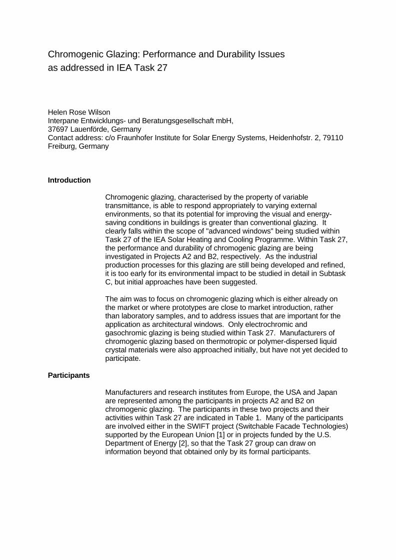
Chromogenic Glazing: Performance and Durability Issuesas addressed in IEA Task 27
Helen Rose WilsonInterpane Entwicklungs- und Beratungsgesellschaft mbH,37697 Lauenförde, GermanyContact address: c/o Fraunhofer Institute for Solar Energy Systems, Heidenhofstr. 2, 79110Freiburg, Germany
Introduction
Chromogenic glazing, characterised by the property of variabletransmittance, is able to respond appropriately to varying externalenvironments, so that its potential for improving the visual and energy-saving conditions in buildings is greater than conventional glazing. Itclearly falls within the scope of "advanced windows" being studied withinTask 27 of the IEA Solar Heating and Cooling Programme. Within Task 27,the performance and durability of chromogenic glazing are beinginvestigated in Projects A2 and B2, respectively. As the industrialproduction processes for this glazing are still being developed and refined,it is too early for its environmental impact to be studied in detail in SubtaskC, but initial approaches have been suggested.
The aim was to focus on chromogenic glazing which is either already onthe market or where prototypes are close to market introduction, ratherthan laboratory samples, and to address issues that are important for theapplication as architectural windows. Only electrochromic andgasochromic glazing is being studied within Task 27. Manufacturers ofchromogenic glazing based on thermotropic or polymer-dispersed liquidcrystal materials were also approached initially, but have not yet decided toparticipate.
Participants
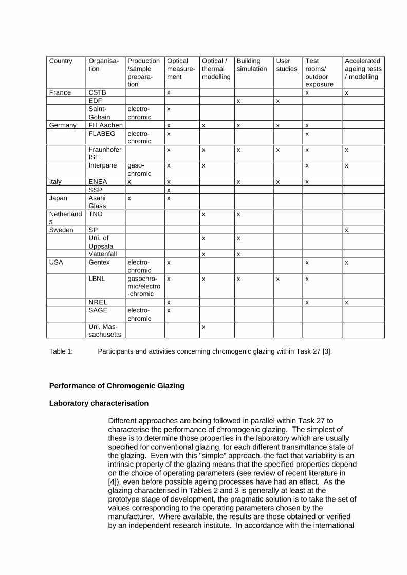
Manufacturers and research institutes from Europe, the USA and Japanare represented among the participants in projects A2 and B2 onchromogenic glazing. The participants in these two projects and theiractivities within Task 27 are indicated in Table 1. Many of the participantsare involved either in the SWIFT project (Switchable Facade Technologies)supported by the European Union [1] or in projects funded by the U.S.Department of Energy [2], so that the Task 27 group can draw oninformation beyond that obtained only by its formal participants.
Country Organisa-tion
Production/sampleprepara-tion
Opticalmeasure-ment
Optical /thermalmodelling
Buildingsimulation
Userstudies
Testrooms/outdoorexposure
Acceleratedageing tests/ modelling
France CSTB x x xEDF x xSaint-Gobain
electro-chromic
x
Germany FH Aachen x x x x xFLABEG electro-
chromicx x
FraunhoferISE
x x x x x x
Interpane gaso-chromic
x x x x
Italy ENEA x x x x xSSP x
Japan AsahiGlass
x x
Netherlands
TNO x x
Sweden SP xUni. ofUppsala
x x
Vattenfall x xUSA Gentex electro-
chromicx x x
LBNL gasochro-mic/electro-chromic
x x x x x
NREL x x xSAGE electro-
chromicx
Uni. Mas-sachusetts
x
Table 1: Participants and activities concerning chromogenic glazing within Task 27 [3].
Performance of Chromogenic Glazing
Laboratory characterisation
Different approaches are being followed in parallel within Task 27 tocharacterise the performance of chromogenic glazing. The simplest ofthese is to determine those properties in the laboratory which are usuallyspecified for conventional glazing, for each different transmittance state ofthe glazing. Even with this "simple" approach, the fact that variability is anintrinsic property of the glazing means that the specified properties dependon the choice of operating parameters (see review of recent literature in[4]), even before possible ageing processes have had an effect. As theglazing characterised in Tables 2 and 3 is generally at least at theprototype stage of development, the pragmatic solution is to take the set ofvalues corresponding to the operating parameters chosen by themanufacturer. Where available, the results are those obtained or verifiedby an independent research institute. In accordance with the international
scope of IEA, the technical glazing properties are evaluated according toISO 9050 and ISO 15099 wherever sufficient information was available todo so.
Manu-facturer
Type Construction Develop-ment stage
Maximumarea
Source ofdata inTable 3
Calculationprogram
Asahi electrochromic,all-solid-state
unspecified unspeci-fied
unspeci-fied
Asahi [5] WINDOW5[6]
FLABEG electrochromic,polymer laminate
9 mm EC laminate: 16mm Ar: low-e on 4 mmfloat
pilotproduction
0.9 m x2 m
ENEA [7],FLABEG[8]
notspecified
Gentex electrochromic,solution-phase
single solution-phaselayer between two floatpanes
laboratory 1 m x 1 m Gentex [9] WINDOW5[6]
Interpane gasochromic 4 mm float with GCcoating: 8 mm Ar: 4 mmfloat: 16 mm Ar: low-eon 4 mm float
pilotproduction
1.5 m x1.8 m
OBU [10],Interpane[11]
WINDOW5[6]
SAGE electrochromic,all-solid-state
float with EC and low-ecoating: 12 mm air:float
pilot line N/A SAGE [12] notspecified
Saint-Gobain
electrochromic,all-solid-state
7 mm EC laminate: 16mm Ar: low-e on 4 mmfloat
prototype N/A Saint-Gobain[13]
WINDOW5[6]
Table 2: Summary description of chromogenic glazing investigated in Task 27.
bleached colouredManu-facturer
Tvis Rvis, out SHGC(g value,TSET)
U valueWm-2K-1
Inter-mediatestatespossible
Tvis Rvis, out SHGC(g value,TSET)
U valueWm-2K-1
Standard
Asahi 0.70 0.11 yes 0.20 0.06 ISO9050FLABEG 0.50 0.36 1.3 yes 0.15 0.12 1.3 DIN
52619Gentexdevice 1
0.81 0.09 yes 0.05 0.05 ISO9050
Gentexdevice 2
0.82 0.09 yes 0.25 0.06 ISO9050
Inter-pane
0.58 0.25 0.49 1.0 not yet 0.13 0.07 0.13 1.0 ISO9050/ISO15099
SAGE 0.70 0.51 1.9 yes 0.04 0.09 1.9 NFRCSaint-Gobain
0.47 0.14 0.28 1.4 yes 0.10 0.08 0.11 1.4 ISO9050/ISO15099
Table 3: Technical properties of chromogenic glazing treated in Task 27.
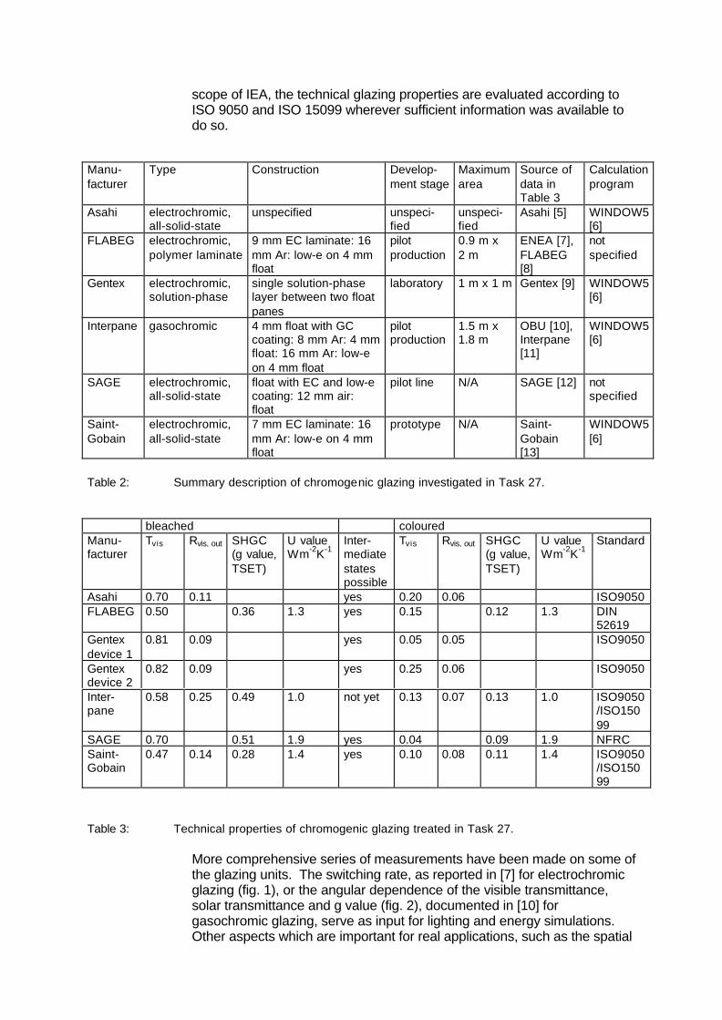
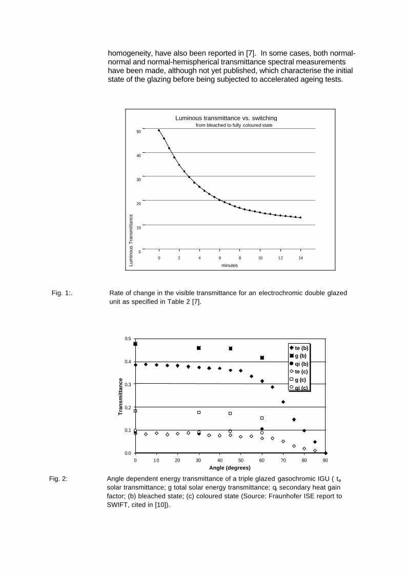
More comprehensive series of measurements have been made on some ofthe glazing units. The switching rate, as reported in [7] for electrochromicglazing (fig. 1), or the angular dependence of the visible transmittance,solar transmittance and g value (fig. 2), documented in [10] forgasochromic glazing, serve as input for lighting and energy simulations.Other aspects which are important for real applications, such as the spatial
homogeneity, have also been reported in [7]. In some cases, both normal-normal and normal-hemispherical transmittance spectral measurementshave been made, although not yet published, which characterise the initialstate of the glazing before being subjected to accelerated ageing tests.
0 2 4 6 8 10 12 14
minutes
0
10
20
30
40
50Lu
min
ous
Tra
nsm
ittan
ce
Luminous transmittance vs. switchingfrom bleached to fully coloured state
Fig. 1:. Rate of change in the visible transmittance for an electrochromic double glazedunit as specified in Table 2 [7].
0.0
0.1
0.2
0.3
0.4
0.5
0 10 20 30 40 50 60 70 80 90
Angle (degrees)
Tra
nsm
itta
nce
te (b)g (b)qi (b)te (c)g (c)qi (c)
Fig. 2: Angle dependent energy transmittance of a triple glazed gasochromic IGU ( tesolar transmittance; g total solar energy transmittance; qi secondary heat gainfactor; (b) bleached state; (c) coloured state (Source: Fraunhofer ISE report toSWIFT, cited in [10]).
Monitored test rooms
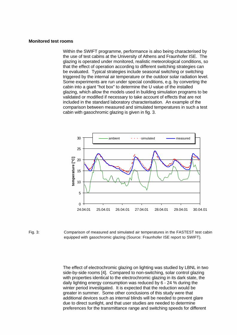
Within the SWIFT programme, performance is also being characterised bythe use of test cabins at the University of Athens and Fraunhofer ISE. Theglazing is operated under monitored, realistic meteorological conditions, sothat the effect of operation according to different switching strategies canbe evaluated. Typical strategies include seasonal switching or switchingtriggered by the internal air temperature or the outdoor solar radiation level.Some experiments are run under special conditions, e.g. by converting thecabin into a giant "hot box" to determine the U value of the installedglazing, which allow the models used in building simulation programs to bevalidated or modified if necessary to take account of effects that are notincluded in the standard laboratory characterisation. An example of thecomparison between measured and simulated temperatures in such a testcabin with gasochromic glazing is given in fig. 3.
0
5
10
15
20
25
30
24.04.01 25.04.01 26.04.01 27.04.01 28.04.01 29.04.01 30.04.01
tem
per
atu
re [°
C]
ambient simulated measured
Fig. 3: Comparison of measured and simulated air temperatures in the FASTEST test cabinequipped with gasochromic glazing (Source: Fraunhofer ISE report to SWIFT).
The effect of electrochromic glazing on lighting was studied by LBNL in twoside-by-side rooms [4]. Compared to non-switching, solar control glazingwith properties identical to the electrochromic glazing in its dark state, thedaily lighting energy consumption was reduced by 6 - 24 % during thewinter period investigated. It is expected that the reduction would begreater in summer. Some other conclusions of this study were thatadditional devices such as internal blinds will be needed to prevent glaredue to direct sunlight, and that user studies are needed to determinepreferences for the transmittance range and switching speeds for different
tasks, and to evaluate occupant reactions to the blue-toned lighttransmitted by the glazing in its coloured state.
In addition, electrochromic windows have been tested in LBNL's MobileWindow Thermal Test Facility (MoWiTT).
Building simulation
Since the first detailed sets of optical and thermal data for chromogenicglazing were provided to Task 27 in 2002, it is expected that results ofbuilding energy and lighting simulation will be presented at the Ottawameeting. The participants will use a range of simulation programs to studythe effects of location (Stockholm, Brussels, Rome, Arizona) and controlstrategy, using the reference office defined in project A1. After simulatingthe glazing in each of its two extreme states for the whole year, initially acontrol strategy depending on the indoor operative temperature will besimulated (coloured when the temperature rises above 26 °C, bleachedwhen the temperature falls below 24 °C). In addition to hourly distributionsand totals for the energy consumed for heating, cooling and lighting, theoutputs should include information on the number of hours per year in eachstate, the annual number of switching cycles and the external surfacetemperatures of the glazing.
Parallel to this, work on lighting simulation is proceeding, for instance bythe group at TNO, using the criteria developed in the REVIS project toassess visual comfort. Initial results were presented at the combinedmeeting with Task 27 and Task 31 participants in April 2002 [14].
Ideally, the simulation work will allow both visual-comfort and energy-saving criteria to be applied, so that optimal control strategies can beidentified.
User studies
ENEA has conducted the first user study within the framework of Task 27,in which 30 subjects responded to a questionnaire on their reactions toworking in a room equipped with electrochromic windows [15]. The testpersons were invited to modify both the electrochromic glazing setting andthe artificial lighting level in the room according to their personalpreference. It was noted that the intermediate transmittance levels wereseldom used - the glazing was either completely darkened when it wassunny outdoors, or the glazing was kept bleached if the sky was overcast.In many cases, the subject chose to colour the window and have someartificial lighting as well, in order to obtain a more uniform light distributionin the room. This study also confirmed the need for an additional internalblind to prevent glare due to direct sunlight. Although a northern windowwas also kept permanently in the clear state, most users were notdisturbed by the two differently coloured windows in their field of view. Arange of opinions was registered concerning the alternatives of manual orautomated control for the glazing, blind and artificial lighting, but thegeneral preference was for individual control.
User studies are being conducted as part of the SWIFT project by TNO,Eindhoven and Fraunhofer ISE, in office rooms equipped withelectrochromic and gasochromic glazing.
Durability of chromogenic glazing
A product is generally considered to be durable if its properties remainunchanged over a long period of time. The intrinsic difficulty incharacterising the durability of chromogenic glazing is that it is originallyintended to be changeable, so that not only the number of properties whichare to "remain unchanged" has to be multiplied by the number of states theglazing unit can assume, but also the intended rate of change is anadditional important property in itself. If durability tests, in accordance withone main approach, are to be accelerated by increasing the level of anassumed environmental stress, questions immediately arise concerning themost relevant combinations of the sample state (constant at which level,switching between which levels at which frequency) and the environmentalstresses applied individually or in combination, maintained at a constantlevel or cycled.
For the other main approach to durability testing, real-time testing,chromogenic glazing suffers the disadvantage of being a very youngproduct. Even those products which are already on the market have beenthere for only a few years, and even these are still undergoing furtherdevelopment and optimisation. Naturally, the rate of development isgreater still for products at the prototype stage or earlier. As aconsequence, the results of real-time testing are only of limited validity.
As stated clearly in a paper summarising an international forum ondurability of electrochromic windows, "there are far too many unansweredquestions to identify the definitive sets of testing conditions to evaluate thedurability of any particular device" [16]. In Project B2, the approach hasbeen adopted of trying to answer some of these open questions byadapting the initial risk analysis from the general durability methodology ofProject B1 to the specifics of chromogenic glazing [17].
Initial risk analysis for chromogenic glazing
In accordance with Task 27's focus on applications "for building envelopes"and the manufacturers' stipulations, the object of investigation is theoperational chromogenic glazing unit, not its component materials. Thegeneral requirements for performance were identified by B2 participants asbeing:
- high solar gain when heating is required, low solar gain when cooling isrequired
- "sufficiently" high or low visible transmittance, depending on lightingconditions and requirements
- acceptable switching times - on the order of minutes- low U value- acceptable power consumption- 20 years service lifetime
The main quantities describing the severity of environmental stressexpected under operational conditions were characterised as follows:
- outdoor air temperatures between -20 °C and 45 °C- outer pane temperatures between -20 °C and ~80°C- solar radiation intensity between 0 and 1100 Wm-2
- solar UV radiation intensity between 0 and 50 Wm-2
- large thermal gradients between shaded and unshaded areas of glazing(electrochromic DGU in frame, gasochromic TGU in frame)
- high relative humidity- mechanical loads as for conventional glazing (wind, snow, structural,
thermal shock/stress)
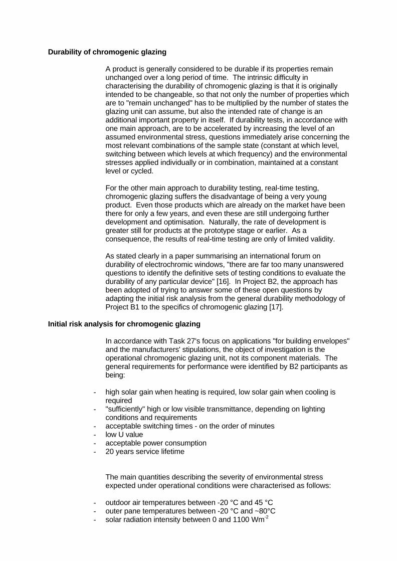
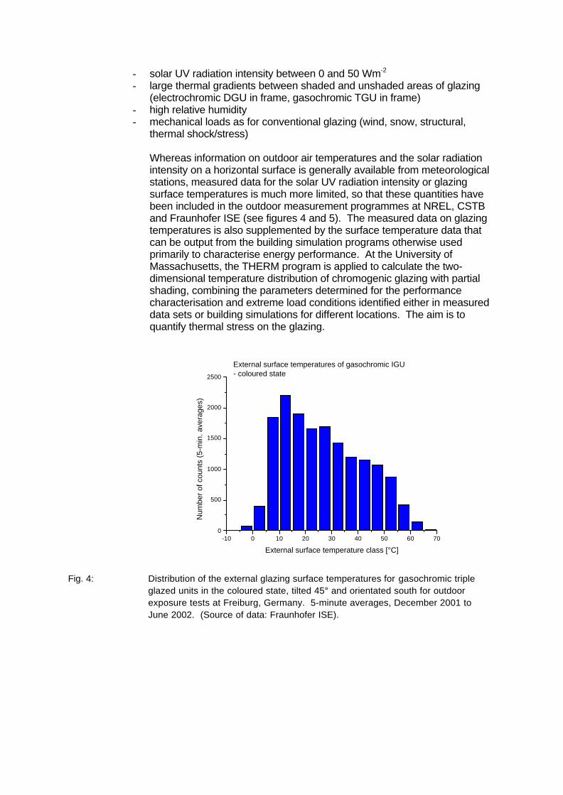
Whereas information on outdoor air temperatures and the solar radiationintensity on a horizontal surface is generally available from meteorologicalstations, measured data for the solar UV radiation intensity or glazingsurface temperatures is much more limited, so that these quantities havebeen included in the outdoor measurement programmes at NREL, CSTBand Fraunhofer ISE (see figures 4 and 5). The measured data on glazingtemperatures is also supplemented by the surface temperature data thatcan be output from the building simulation programs otherwise usedprimarily to characterise energy performance. At the University ofMassachusetts, the THERM program is applied to calculate the two-dimensional temperature distribution of chromogenic glazing with partialshading, combining the parameters determined for the performancecharacterisation and extreme load conditions identified either in measureddata sets or building simulations for different locations. The aim is toquantify thermal stress on the glazing.
-10 0 10 20 30 40 50 60 700
500
1000
1500
2000
2500
External surface temperatures of gasochromic IGU- coloured state
Num
ber
of c
ount
s (5
-min
. ave
rage
s)
External surface temperature class [°C]
Fig. 4: Distribution of the external glazing surface temperatures for gasochromic tripleglazed units in the coloured state, tilted 45° and orientated south for outdoorexposure tests at Freiburg, Germany. 5-minute averages, December 2001 toJune 2002. (Source of data: Fraunhofer ISE).
0 10 20 30 40 50 600
10000
20000
30000
40000
num
ber o
f cou
nts
(5-m
in. a
vera
ges)
UVA radiation class (on horizontal plane) [Wm-2]
Fig. 5: Frequency distribution of UVA radiation on horizontal plane, measured atFreiburg, Germany. 5-minute averages, December 2001 to June 2002. (Sourceof data: Fraunhofer ISE).
Based on the general requirements for performance, a list of criticalfunctional properties for chromogenic glazing was prepared, which is to befound in Appendix I. The test methods for evaluating these properties,which are also listed, were fairly obvious; what was less obvious was theeffect that a change in these properties would have on the glazingperformance in a building. Two different approaches to set performancebenchmarks are documented in the appendix. One is again to draw on thebuilding simulation expertise within Task 27 and carry out parametersensitivity studies, e.g. to characterise the effect of the ratio of maximum tominimum g value (SHGC or TSET) on the total energy demand in thereference office defined in Project A1, and compare the results to goodsolar control or low-e glazing. In other cases, such as the assessment ofappearance or the resistance to mechanical loads, it is consideredadequate to apply existing standards for conventional glazing. A list ofrelevant international and national standards which was collated by B2participants is given in Appendix II.
The identified possible damage failure modes include the glazing remainingconstantly bleached or coloured, switching becoming unacceptably slow,the switching range decreasing, the appearance becoming inhomogeneous(critical in ”steady state”, less critical during switching), the upper and lowertransmittance values shifting, delamination, haze, blur, yellowing andcolour shifts.
Finally, in designing the initial series of accelerated ageing tests,experience was pooled regarding the most critical factors that can lead todegradation; elevated temperatures (particularly for the glazing in thecoloured state), UV radiation, sudden spatial or temporal temperaturegradients, air leakage into glazed unit, high humidity, condensation,inappropriate charge injection for electrochromic devices or inappropriategas supply for gasochromic devices, switching frequency, prolongedperiods without switching and mechanical deformation.
Test methods
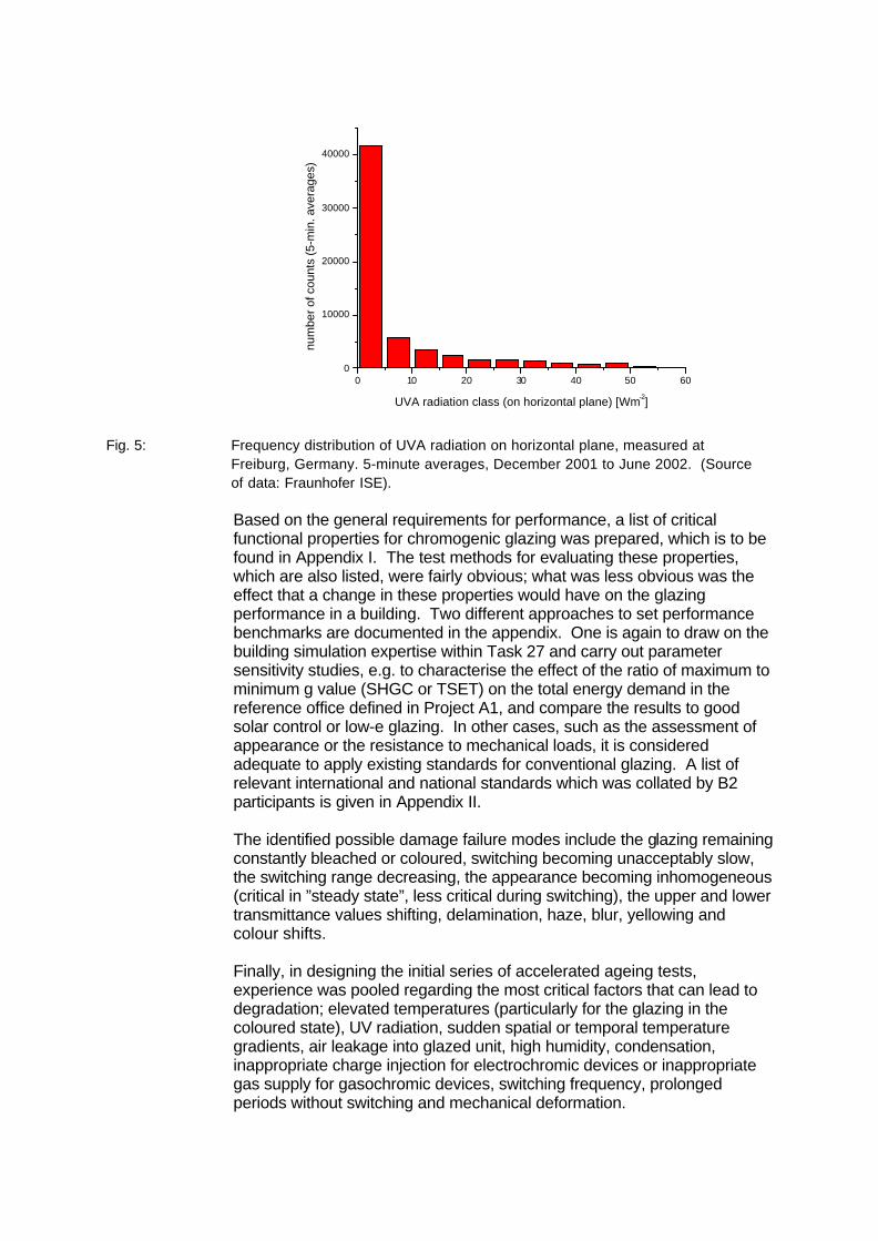
In the USA, a test method developed by NREL has been accepted as astandard for assessing the durability of absorptive electrochromic coatingson sealed insulating glass units [18]. It involves the exposure ofelectrochromic windows (ECW) to simulated solar irradiance in atemperature- and humidity-controlled chamber at selected sampletemperatures ranging from 70°C to 105°C while the ECW's are cyclicallycoloured and bleached, with continuous monitoring of the photopic (visible)transmittance at ~22°C and the elevated temperatures (fig. 6). Therequired performance parameter is that after 50,000 cycles, the photopictransmittance ratio, the ratio of the visible transmittance in the bleachedstate to that in the coloured state, exceed 4:1 and the visible transmittancein the bleached state exceed 0.50.
Fig. 6: Sample exposure plane inside the accelerated weathering unit at NREL foraccelerated testing of electrochromic windows according to [18] (Source: NREL).
Within the European SWIFT project, a set of five qualification tests hasbeen chosen for initial accelerated testing of complete electrochromic andgasochromic systems at CSTB and Fraunhofer ISE:
1 Cycling at room temperature (1 full cycle period of 40 minutes); totalnumber of cycles 3600
2 Cycling at constant air temperature of 65°C, HR 5-25% and solarradiation (1 sun) with 40-minute cycles as 1st test, total number ofcycles 3600
3 Cycling at constant air temperature of 5°C, (maximum period of 2 hoursfor full cycle), total number of cycles 3600 if possible
4 Thermal cycling from –18°C to 53°C (ramp of 14°C/h) and RHaccording to prEN 1279-2; chromogenic unit constantly in dark state,cycling performance at room temperature before and after test asindicator. Also characterise a coloured reference sample without load(stored for 77 days without switching at room temperature in the dark)for comparison.
5 External thermal shock test analogous to EN12975-2, section 5.5. (1hour exposure of the window in the coloured state to solar radiation >850 Wm-2, Tamb > 25 °C; thereafter 15 minutes spraying with water ata temperature of < 25 °C, flowrate in the range 0.03 - 0.05 kg s-1 persquare metre of glazing area; test to be performed twice).
The performance of the tested glazing is characterised bynormal/hemispherical and normal-normal transmittance spectra (300-2500nm) in the two limit states (bleached and coloured), from which the visibleand solar transmittance, and the colour co-ordinates are obtained, anddτ550nm/dt. The measurements are made at the beginning and end of eachtest, and four further times during tests 1, 2 and 3. Visual observations arealso noted or photographed. The aim of these pictures and measurementsis to detect changes in optical appearance, performance (transmittance incoloured and bleached states, and switching rate), spatial homogeneityand light scattering.
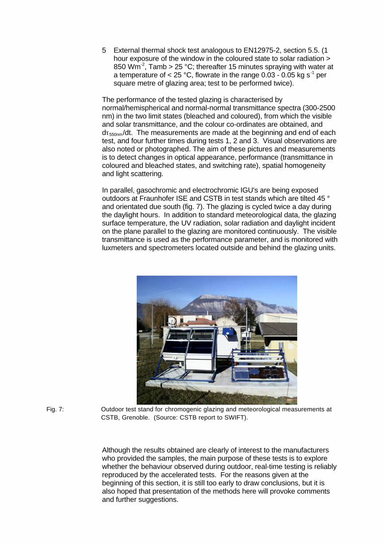
In parallel, gasochromic and electrochromic IGU's are being exposedoutdoors at Fraunhofer ISE and CSTB in test stands which are tilted 45 °and orientated due south (fig. 7). The glazing is cycled twice a day duringthe daylight hours. In addition to standard meteorological data, the glazingsurface temperature, the UV radiation, solar radiation and daylight incidenton the plane parallel to the glazing are monitored continuously. The visibletransmittance is used as the performance parameter, and is monitored withluxmeters and spectrometers located outside and behind the glazing units.
Fig. 7: Outdoor test stand for chromogenic glazing and meteorological measurements atCSTB, Grenoble. (Source: CSTB report to SWIFT).
Although the results obtained are clearly of interest to the manufacturerswho provided the samples, the main purpose of these tests is to explorewhether the behaviour observed during outdoor, real-time testing is reliablyreproduced by the accelerated tests. For the reasons given at thebeginning of this section, it is still too early to draw conclusions, but it isalso hoped that presentation of the methods here will provoke commentsand further suggestions.
Conclusions
Within IEA Task 27, co-operation between companies that are developingand producing chromogenic windows, and research institutes withsophisticated measurement and computer simulation facilities, has thepotential to accelerate comprehensive characterisation of the performanceand durability of these dynamic windows. Initial results of these combinedefforts are indicated in this paper. Further work by the group should pavethe way for international harmonisation of standards relevant to thesewindows, and demonstrate the lighting and energy-saving benefits ofchromogenic windows, promoting their acceptance among users aroundthe world.
Acknowledgements
The author sincerely thanks the following colleagues for their contributionsto this paper: Mike Rubin and Eleanor Lee(LBNL), Xavier Fanton (Saint-Gobain), Dave Theiste (Gentex), Mike Myser and Helen Sanders (SAGE),Jens Cardinal (FLABEG), Harald Hagenström (Interpane), MichaelHutchins (OBU), Michele Zinzi (ENEA), Werner Platzer and Markus Heck(Fraunhofer ISE), Bruno Chevalier (CSTB), Roland Pitts and GaryJorgenson (NREL), Junichi Nagai (ASAHI), Bo Carlsson (SP), CharlieCurcija (Uni. Massachusetts), Dick van Dijk (TNO). Much of the work byEuropean participants was within the SWIFT project, which is supported bythe European Commission under the Fifth Framework Programme,Contract No. ENK6-CT-1999-00012. U.S. participants were supported by theDepartment of Energy, Office of Buildings Technology.
References
1 SWIFT, Switchable Façade Technology, European Commission FP5Contract No. ENK6-CT-1999-00012; Co-ordinator Fraunhofer ISE,Germany.
2 Details of the DOE projects and the Window Industry TechnologyRoadmap are available from the Office of Building Technology, Stateand Community Programs, Energy Efficiency and Renewable Energy,U.S. Department of Energy. www.eren.doe.gov/buildings
3 IEA-SHCP Task 27 information brochure, www.iea-shc-task27.org4 E.S. Lee, D.L. DiBartolomeo. Application issues for large-area
electrochromic windows in commercial buildings, Sol. En. Mat. & Sol.Cells 71 (2002) 465 - 491
5 J. Nagai. Spectral data submitted within Task 276 WINDOW 5 Program Description. Report LBNL-44789, Windows and
Daylighting Group, LBNL, Berkeley, California, USA7 G. Fasano, A. Maccari, P. Polato, M. Zinzi. Optical characterization of a
50x50 cm electrochromic device. Conf. Proc. Eurosun 2002, 23rd-26thJune 2002, Bologna, Italy. (CD-ROM)
8 FLABEG EControl ®, technical data sheet. www.flabeg.com9 D. Theiste. Spectral data submitted within Task 2710 H.R. Wilson, R. Blessing, H. Hagenström, M.G. Hutchins, D. Dvorjetski,
W.J. Platzer. The optical properties of gasochromic glazing. Conf.Proc. 4th International Conference on Coatings on Glass, 3rd - 7thNovember, 2002. Braunschweig, Germany
11 H.R. Wilson. Spectral data submitted within Task 27
12 M. Myser, personal communication; SAGE technical data sheet.www.sage-ec.com
13 X. Fanton. Spectral data submitted within Task 2714 H.A.L. van Dijk. Daylighting characterisation of innovative glazing
systems. Presentation at joint meeting of IEA-SHCP Tasks 27 and 31,10th April 2002, Copenhagen.
15 M. Zinzi, ENEA. Personal communication16 A.W. Czanderna, D.K. Benson, G.J. Jorgensen, J.-G. Zhang, C.E.
Tracy, S.K. Deb. Durability issues and service lifetime prediction ofelectrochromic windows for buildings applications. Sol. En. Mat. & Sol.Cells 56 (1999) 419 - 436
17 B. Carlsson. Durability Assessment and Service Life Prediction, in A.W.Czanderna (Ed.), Performance and Durability Assessment of OpticalMaterials for Solar Thermal Systems. Final Report of the WorkingGroup: Materials in Solar Thermal Collectors, Elsevier, Amsterdam (tobe published)
18 ASTM E 2141 - 01 Standard Test Methods for Assessing the Durabilityof Absorptive Electrochromic Coatings on Sealed Insulating GlassUnits (2001-08)
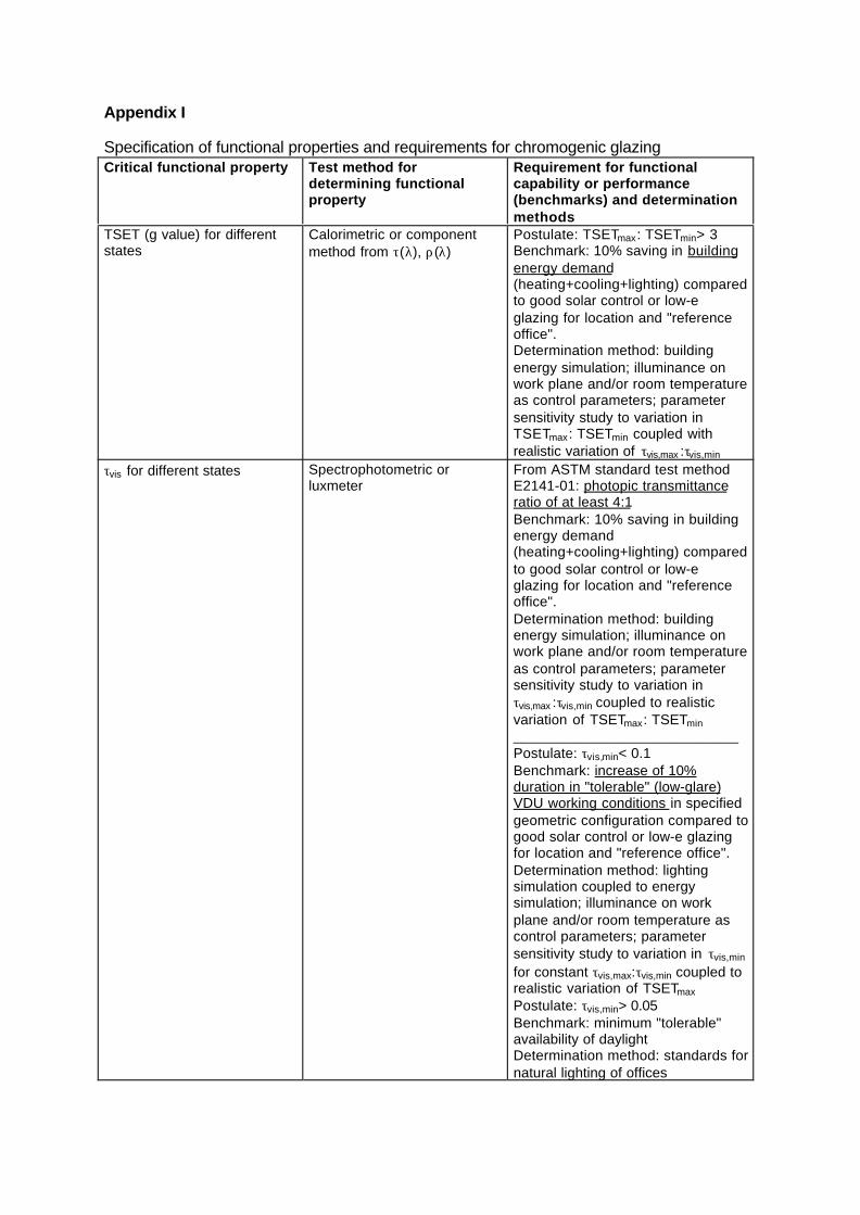
Appendix I
Specification of functional properties and requirements for chromogenic glazingCritical functional property Test method for
determining functionalproperty
Requirement for functionalcapability or performance(benchmarks) and determinationmethods
TSET (g value) for differentstates
Calorimetric or componentmethod from τ(λ), ρ(λ)
Postulate: TSETmax: TSETmin> 3Benchmark: 10% saving in buildingenergy demand(heating+cooling+lighting) comparedto good solar control or low-eglazing for location and "referenceoffice".Determination method: buildingenergy simulation; illuminance onwork plane and/or room temperatureas control parameters; parametersensitivity study to variation inTSETmax: TSETmin coupled withrealistic variation of τvis,max :τvis,min
τvis for different states Spectrophotometric orluxmeter
From ASTM standard test methodE2141-01: photopic transmittanceratio of at least 4:1Benchmark: 10% saving in buildingenergy demand(heating+cooling+lighting) comparedto good solar control or low-eglazing for location and "referenceoffice".Determination method: buildingenergy simulation; illuminance onwork plane and/or room temperatureas control parameters; parametersensitivity study to variation inτvis,max :τvis,min coupled to realisticvariation of TSETmax: TSETmin____________________________Postulate: τvis,min< 0.1Benchmark: increase of 10%duration in "tolerable" (low-glare)VDU working conditions in specifiedgeometric configuration compared togood solar control or low-e glazingfor location and "reference office".Determination method: lightingsimulation coupled to energysimulation; illuminance on workplane and/or room temperature ascontrol parameters; parametersensitivity study to variation in τvis,min
for constant τvis,max:τvis,min coupled torealistic variation of TSETmax
Postulate: τvis,min> 0.05Benchmark: minimum "tolerable"availability of daylightDetermination method: standards fornatural lighting of offices
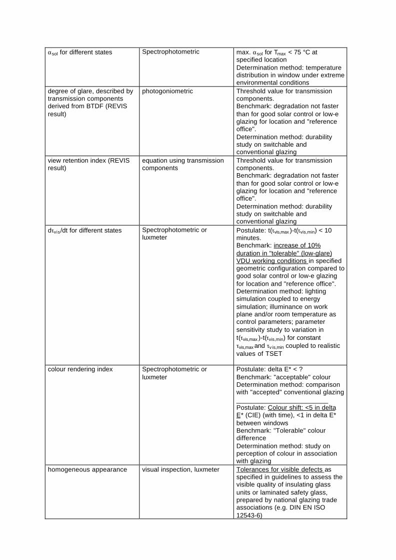
αsol for different states Spectrophotometric max. αsol for Tmax < 75 °C atspecified locationDetermination method: temperaturedistribution in window under extremeenvironmental conditions
degree of glare, described bytransmission componentsderived from BTDF (REVISresult)
photogoniometric Threshold value for transmissioncomponents.Benchmark: degradation not fasterthan for good solar control or low-eglazing for location and "referenceoffice".Determination method: durabilitystudy on switchable andconventional glazing
view retention index (REVISresult)
equation using transmissioncomponents
Threshold value for transmissioncomponents.Benchmark: degradation not fasterthan for good solar control or low-eglazing for location and "referenceoffice".Determination method: durabilitystudy on switchable andconventional glazing
dτvis/dt for different states Spectrophotometric orluxmeter
Postulate: t(τvis,max )-t(τvis,min) < 10minutes.Benchmark: increase of 10%duration in "tolerable" (low-glare)VDU working conditions in specifiedgeometric configuration compared togood solar control or low-e glazingfor location and "reference office".Determination method: lightingsimulation coupled to energysimulation; illuminance on workplane and/or room temperature ascontrol parameters; parametersensitivity study to variation int(τvis,max )-t(τvis,min) for constantτvis,max and τv is,min coupled to realisticvalues of TSET
colour rendering index Spectrophotometric orluxmeter
Postulate: delta E* < ?Benchmark: "acceptable" colourDetermination method: comparisonwith "accepted" conventional glazing_________________________Postulate: Colour shift: <5 in deltaE* (CIE) (with time), <1 in delta E*between windowsBenchmark: "Tolerable" colourdifferenceDetermination method: study onperception of colour in associationwith glazing
homogeneous appearance visual inspection, luxmeter Tolerances for visible defects asspecified in guidelines to assess thevisible quality of insulating glassunits or laminated safety glass,prepared by national glazing tradeassociations (e.g. DIN EN ISO12543-6)
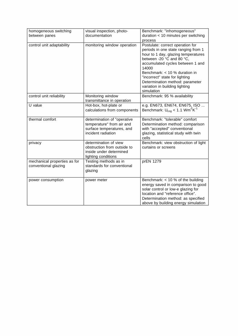
homogeneous switchingbetween panes
visual inspection, photo-documentation
Benchmark: "inhomogeneous"duration < 10 minutes per switchingprocess
control unit adaptability monitoring window operation Postulate: correct operation forperiods in one state ranging from 1hour to 1 day, glazing temperaturesbetween -20 °C and 80 °C,accumulated cycles between 1 and14000Benchmark: < 10 % duration in"incorrect" state for lightingDetermination method: parametervariation in building lightingsimulation
control unit reliability Monitoring windowtransmittance in operation
Benchmark: 95 % availability
U value Hot-box, hot-plate orcalculations from components
e.g. EN673, EN674, EN675, ISO ...Benchmark: Ucog < 1.1 Wm-2K-1
thermal comfort determination of "operativetemperature" from air andsurface temperatures, andincident radiation
Benchmark: "tolerable" comfortDetermination method: comparisonwith "accepted" conventionalglazing, statistical study with twincells
privacy determination of viewobstruction from outside toinside under determinedlighting conditions
Benchmark: view obstruction of lightcurtains or screens
mechanical properties as forconventional glazing
Testing methods as instandards for conventionalglazing
prEN 1279
power consumption power meter Benchmark: < 10 % of the buildingenergy saved in comparison to goodsolar control or low-e glazing forlocation and "reference office".Determination method: as specifiedabove by building energy simulation
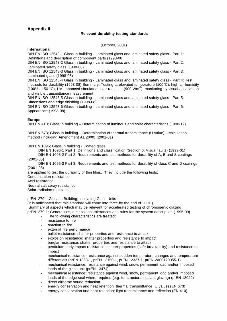
Appendix IIRelevant durability testing standards
(October, 2001)InternationalDIN EN ISO 12543-1 Glass in building - Laminated glass and laminated safety glass - Part 1:Definitions and description of component parts (1998-08)DIN EN ISO 12543-2 Glass in building - Laminated glass and laminated safety glass - Part 2:Laminated safety glass (1998-08)DIN EN ISO 12543-3 Glass in building - Laminated glass and laminated safety glass - Part 3:Laminated glass (1998-08)DIN EN ISO 12543-4 Glass in building - Laminated glass and laminated safety glass - Part 4: Testmethods for durability (1998-08) Summary: Testing at elevated temperature (100°C), high air humidity(100% at 50 °C), UV-enhanced simulated solar radiation (900 Wm-2), monitoring by visual observationand visible transmittance measurementDIN EN ISO 12543-5 Glass in building - Laminated glass and laminated safety glass - Part 5:Dimensions and edge finishing (1998-08)DIN EN ISO 12543-6 Glass in building - Laminated glass and laminated safety glass - Part 6:Appearance (1998-08)
EuropeDIN EN 410; Glass in building – Determination of luminous and solar characteristics (1998-12)
DIN EN 673; Glass in building – Determination of thermal transmittance (U value) – calculationmethod (including Amendment A1:2000) (2001-01)
DIN EN 1096; Glass in building - Coated glassDIN EN 1096-1 Part 1: Definitions and classification (Section 6; Visual faults) (1999-01)DIN EN 1096-2 Part 2: Requirements and test methods for durability of A, B and S coatings
(2001-05)DIN EN 1096-3 Part 3: Requirements and test methods for durability of class C and D coatings
(2001-05)are applied to test the durability of thin films. They include the following tests:Condensation resistanceAcid resistanceNeutral salt spray resistanceSolar radiation resistance
prEN1279 – Glass in Building; Insulating Glass Units(It is anticipated that this standard will come into force by the end of 2001.) Summary of aspects which may be relevant for accelerated testing of chromogenic glazingprEN1279-1; Generalities, dimensional tolerances and rules for the system description (1995-09)
- The following characteristics are treated:- resistance to fire- reaction to fire- external fire performance- bullet resistance: shatter properties and resistance to attack- explosion resistance: shatter properties and resistance to impact- burglar resistance: shatter properties and resistance to attack- pendulum body impact resistance: shatter properties (safe breakability) and resistance to
impact- mechanical resistance: resistance against sudden temperature changes and temperature
differentials (prEN 1863-1, prEN 12150-1, prEN 12337-1, prEN WI00129055-1)- mechanical resistance: resistance against wind, snow, permanent load and/or imposed
loads of the glass unit (prEN 13474)- mechanical resistance: resistance against wind, snow, permanent load and/or imposed
loads of the edge seal where required (e.g. for structural sealant glazing) (prEN 13022)- direct airborne sound reduction- energy conservation and heat retention; thermal transmittance (U value) (EN 673)- energy conservation and heat retention; light transmittance and reflection (EN 410)
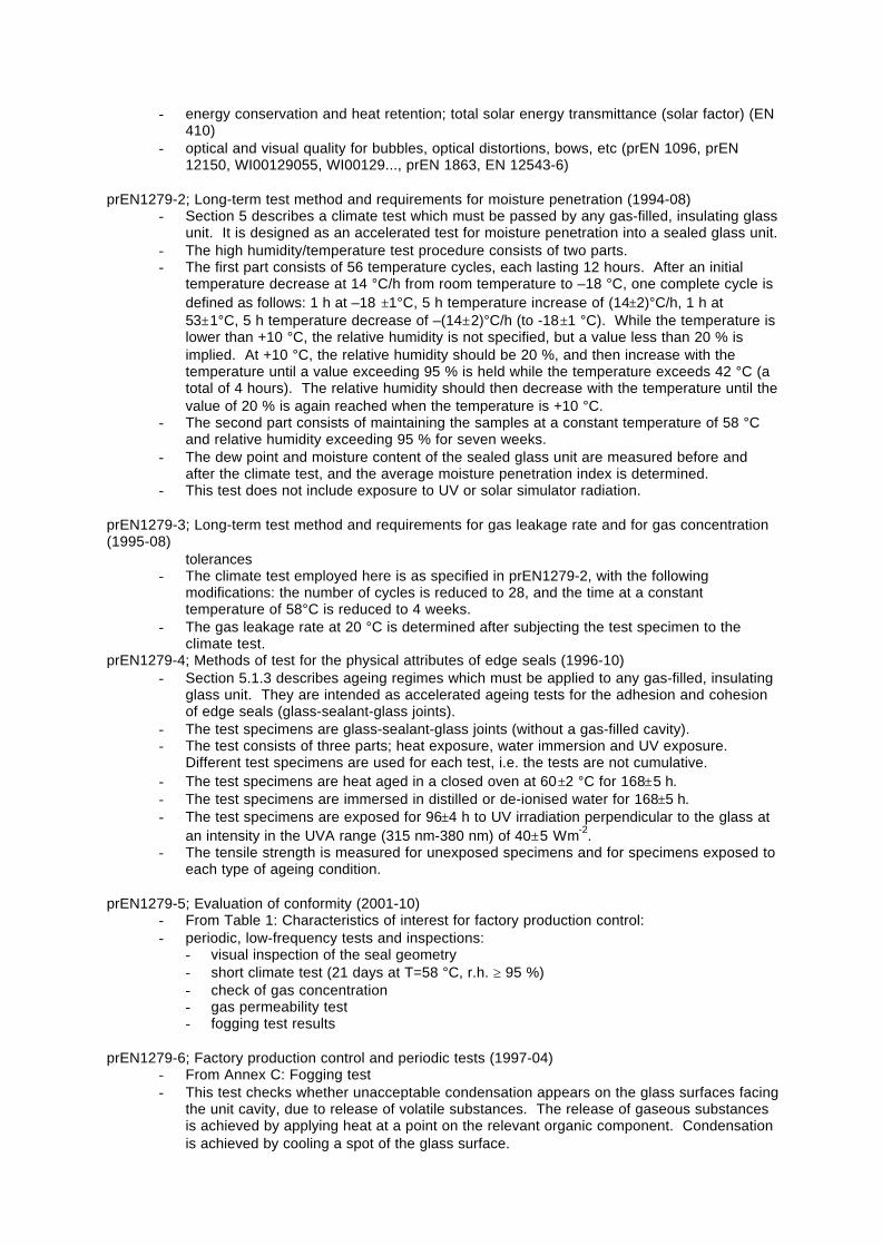
- energy conservation and heat retention; total solar energy transmittance (solar factor) (EN410)
- optical and visual quality for bubbles, optical distortions, bows, etc (prEN 1096, prEN12150, WI00129055, WI00129..., prEN 1863, EN 12543-6)
prEN1279-2; Long-term test method and requirements for moisture penetration (1994-08)- Section 5 describes a climate test which must be passed by any gas-filled, insulating glass
unit. It is designed as an accelerated test for moisture penetration into a sealed glass unit.- The high humidity/temperature test procedure consists of two parts.- The first part consists of 56 temperature cycles, each lasting 12 hours. After an initial
temperature decrease at 14 °C/h from room temperature to –18 °C, one complete cycle isdefined as follows: 1 h at –18 ±1°C, 5 h temperature increase of (14±2)°C/h, 1 h at53±1°C, 5 h temperature decrease of –(14±2)°C/h (to -18±1 °C). While the temperature islower than +10 °C, the relative humidity is not specified, but a value less than 20 % isimplied. At +10 °C, the relative humidity should be 20 %, and then increase with thetemperature until a value exceeding 95 % is held while the temperature exceeds 42 °C (atotal of 4 hours). The relative humidity should then decrease with the temperature until thevalue of 20 % is again reached when the temperature is +10 °C.
- The second part consists of maintaining the samples at a constant temperature of 58 °Cand relative humidity exceeding 95 % for seven weeks.
- The dew point and moisture content of the sealed glass unit are measured before andafter the climate test, and the average moisture penetration index is determined.
- This test does not include exposure to UV or solar simulator radiation.
prEN1279-3; Long-term test method and requirements for gas leakage rate and for gas concentration(1995-08)
tolerances- The climate test employed here is as specified in prEN1279-2, with the following
modifications: the number of cycles is reduced to 28, and the time at a constanttemperature of 58°C is reduced to 4 weeks.
- The gas leakage rate at 20 °C is determined after subjecting the test specimen to theclimate test.
prEN1279-4; Methods of test for the physical attributes of edge seals (1996-10)- Section 5.1.3 describes ageing regimes which must be applied to any gas-filled, insulating
glass unit. They are intended as accelerated ageing tests for the adhesion and cohesionof edge seals (glass-sealant-glass joints).
- The test specimens are glass-sealant-glass joints (without a gas-filled cavity).- The test consists of three parts; heat exposure, water immersion and UV exposure.
Different test specimens are used for each test, i.e. the tests are not cumulative.- The test specimens are heat aged in a closed oven at 60±2 °C for 168±5 h.- The test specimens are immersed in distilled or de-ionised water for 168±5 h.- The test specimens are exposed for 96±4 h to UV irradiation perpendicular to the glass at
an intensity in the UVA range (315 nm-380 nm) of 40±5 Wm-2.- The tensile strength is measured for unexposed specimens and for specimens exposed to
each type of ageing condition.
prEN1279-5; Evaluation of conformity (2001-10)- From Table 1: Characteristics of interest for factory production control:- periodic, low-frequency tests and inspections:
- visual inspection of the seal geometry- short climate test (21 days at T=58 °C, r.h. ≥ 95 %)- check of gas concentration- gas permeability test- fogging test results
prEN1279-6; Factory production control and periodic tests (1997-04)- From Annex C: Fogging test- This test checks whether unacceptable condensation appears on the glass surfaces facing
the unit cavity, due to release of volatile substances. The release of gaseous substancesis achieved by applying heat at a point on the relevant organic component. Condensationis achieved by cooling a spot of the glass surface.
- The heated surface temperature nearest to 20 – 30 % of the relevant component is to beheld between 50 and 60 °C.
- The cold spot, which is to have an area of 10 % of the unit surface, is to be 27 – 33 Klower than the heated surface temperature, as specified above.
- The test duration is 168±4 h.- The test specimens are examined for fogging or permanent condensation visually in a
specified viewing box.
DIN EN 1863-1; Glass in building; Heat strengthened soda lime silicate glass – Part 1: Definition anddescription (2000-03)DIN prEN 1863-2; Glass in building - Heat strengthened soda lime silicate glass - Part 2: Evaluation ofconformity (2001-09)
DIN EN 12150-1; Glass in building – Thermally toughened soda lime silicate safety glass - Part 1:Definition and description (2000-11)DIN prEN 12150-2; Glass in building - Thermally toughened soda lime silicate safety glass - Part 2:Evaluation of conformity (2001-09)
DIN EN 12337-1; Glass in building – Chemically strengthened soda lime safety glass - Part 1:Definition and description (2000-11)DIN prEN 12337-2; Glass in building – Chemically strengthened soda lime safety glass - Part 2:Evaluation of conformity (2001-09)
pPrEN 12975-2 Thermal solar systems – Collectors – Part 2: Test methods (1998-01)
DIN EN 12898 Glass in building – Determination of the emissivity (2001-04)
DIN prEN 13022; Glass in building – Structural sealant glazing – Part 3: Sealants, test methods (1998-01)
prEN 13474; Glass in building – Design of glass panes – Part 2: Design for uniformly distributed loads(2000-05)
prEN WI00129055-1; Glass in building – Heat soaked thermally toughened soda lime silicate safetyglass
National:FranceMO3 Humidity test for coated IGU (In-house test developed and conducted by CEBTP or OMV)MO 08 Adherence test for coated IGU (In-house test developed and conducted by CEBTP or OMV)MO20 Compatibility of sealants with glass coating (In-house test developed and conducted by CEBTPor OMV)
(Source of MO standardsCEBTPM.Moïse Riotteau (Dep. Fenêtres et Fassades)Domaine de Saint-PaulB.P. 3778470 Saint-Rémy-Lès-ChevreuseFranceTel. 01.30.85.23.32, Fax 01.30.85.23.20)
GermanyDIN 1286-1 Insulating glass units; air filled; aging behaviour (1994-03)DIN 1286-2 Multiple-walled insulating glazing units; gas filled; aging behaviour, limiting deviations ofgas volume fraction (1989-05)DIN 52 293 Testing of glass; testing the gas tightness of gas-filled insulating glass units (1987-12)DIN V 52 293 Part 2 Testing of glass; testing the gas tightness of gas-filled multiple-walled insulatingglazing units; determination of the loss in gas by gas chromatography and thermal conductivitydetector (1988-11)DIN 52 294 Testing of glass; determination of the loading of desiccants in multiple –walled insulatingglazing units (1988-11)
DIN 52 344 Testing of glass; testing the effect of alternating atmosphere on multilayer insulating glass(1984-05)DIN 52 345 Testing of glass; determination of dew point temperature of insulating glass units;laboratory test (1987-12)
JapanIn Japan, JIS (Japanese Industrial Standard) is the only national standard related to this issue, whichis listed below. However, this is the only necessary minimum and mostly specifications are determinedbetween manufacturers and customers.
List of JIS related to glazing and its testing proceduresA-5759:Adhesive Films for GlazingsB-4111:Solar Water Heater for DwellingsB-7751:Glass-Enclosed Carbon-Arc Type Apparatus for Artificial Light Exposure TestsB-7752:Light-and-Water-Exposure Apparatus (Enclosed Carbon-Arc Type)B-7753:Light-and-Water-Exposure Apparatus (Open-Flame Sunshine Carbon-Arc Type)B-7754:Light-Exposure and Light-and-Water-Exposure Apparatus (Xenon-Arc Lamp Test)R-3106:Testing Method on Transmittance and Reflectance for Daylight and Solar Radiation and SolarHeat Gain Coefficient of Flat GlassR3211:Safety Glass for Road VehiclesR3212:Test Method of Safety Glass for Road Vehicles
USAASTM E 2141 - 01 Standard Test Methods for Assessing the Durability of Absorptive ElectrochromicCoatings on Sealed Insulating Glass Units (2001-08)Summary: Exposure of electrochromic windows (ECW) to simulated solar irradiance in a temperature-and humidity-controlled chamber at selected sample temperatures ranging from 70°C to 105°C whilethe ECW's are cyclically coloured and bleached, monitoring of the photopic (visible) transmittance at~22°C and the elevated temperatures.
1. Fenestration Component Test Methods and Specifications1.1 Perimeter Sealants
1.1.1 AAMA 808.3 "Specifications for Exterior Perimeter Sealing Compounds1.1.2 ASTM C 920 "Specification for Elastomeric Joint Sealants"1.1.3 ASTM C1085 "Standard Specification for Butyl-Based Solvent-Release Sealants"1.1.4 AAMA 803.3 "Specification for Narrow Joint Seam Sealers"1.1.5 ASTM C1311 "Standard Specification for Solvent-Release Sealants"1.1.6 ASTM C834 "Standard Specification for latex Sealants"
1.2 Glazing Compounds1.2.1 ASTM C669 "Standard Specification for Glazing Compounds for Back Bedding andFace Glazing of Metal Sash"1.2.2 ASTM C797 "Standard Practices and Terminology for Use of Oil and Resin BasedPutty and Glazing Compounds"1.2.3 ASTM C741 "Standard Test Method for Accelerated Aging of Wood Sash FaceGlazing Compound"1.2.4 AAMA 802.3 "Specification for Ductile Back Bedding Compound"1.2.5 AAMA 805.2 "Specification for Bonding Type Bedding Compound"1.2.6 AAMA 804.3; 806.3; 807.3 "Specifications for Back Bedding Mastic Type GlazingTapes"1.2.7 ASTM C1281 "Standard Specification for Performed Tape Sealants for GlazingApplications"1.2.8 AAMA 810.1 "Specification for Expanded Cellular Glazing Tapes"
1.3 Gaskets1.3.1 ASTM C509 "Standard Specification for Cellular Elastomeric Preformed Gasketand Sealing Material"1.3.2 ASTM C864 "Specification for Dense Elastomeric Compression Seal Gaskets,Setting Blocks and Spacers"
1.4 Spacers1.4.1 SIGMA A-200 "Voluntary Test Methods and Voluntary Performance QualityAssurance Criteria for Spacers for Sealed Insulating Glass Units"
1.5 Insulating Glass Units1.5.1 ASTM E-774 "Standard Specification for Sealed Insulating Glass Units"
1.6 Glass1.6.1 ASTM C1036 "Standard Specification for Flat Glass"1.6.2 ASTM C1048 "Standard Specification for Heat-Treated Glass"1.6.3 ASTM C1172 "Standard Specification for Laminated Architectural Flat Glass"1.6.4 ASTM E1300 "Determining Load Resistance of Glass in Buildings"
1.7 Desiccant1.7.1 SIGMA A2801 "Recommended Voluntary In-Plant Test Methods and Performance
Criteria for Desiccants for Sealed Insulating Glass Units"
2. Fenestration Assembly Tests
2.1 A number of fenestration tests currently exist for determining performance criteria. Thesetests include Water Penetration (ASTM E-547 or ASTM E-331); Thermal Transmission (ASTMC1199 or AAMA 1503.1); Structural Strength (ASTM E-330); and Chromogenic Functionality(ASTM-TBD). Chromogenic functionality will include but not be limited to maximum controllabilityin the colored and bleached states, their visual appearance, switching time, and photopic contrastratio between the colored and bleached states.
2.2 To meet the requirement of this practice, a product shall be tested to meet therequirements of a nationally recognized product performance standard (see AAMA/NWWDA101/IS2-97) in the following sequence.
2.2.1 The specimen shall be tested in accordance with ASTM E283.2.2.2 The specimen shall be tested in accordance with ASTM E547 (or E331).2.2.3 If specified, the specimen shall be tested in accordance with ASTM C1199 (orAAMA 1503).2.2.4 The specimen shall be tested in accordance to ASTM E330 (at designatedpressures for design classification).2.2.5 The test specimens shall be chosen in accord with Section 8.2.2.6 The test specimen must pass a qualification test, which simulates a suddenrainstorm (water-spray) when the device is operating, by maintaining its chromogenicfunctionality.
2.3 The specimen shall then be exposed to the following accelerated tests (in sequence).2.3.1 The specimen shall be exposed to 1/2 of the specified cycles as referenced inAAMA 910-93 "Voluntary Life Cycle Specifications and Test Methods for ArchitecturalGrade Windows and Sliding Glass Doors."2.3.2 The specimen shall be tested for 100 cycles at 0.75 (75%) of the designatedpressure for the design classification in accordance with ASTM E-1233 "Standard TestMethod for Structural Performance of Exterior Windows, Curtain walls, and Doors byCyclic Static Air Pressure."2.3.3 The specimen shall be exposed to the remaining half of the specified motion cyclesas reference in AAMA 910-93 "Voluntary Life Cycle Specifications and Test Methods forArchitectural Grade Windows and Sliding Glass Doors"
2.4 Upon completion of the accelerated tests, the specimen shall be tested in accordance withSection 2.2.1, 2.2.2, and 2.2.3.2.4.1 The results of these tests shall be reported in Section 9.
Useful websites
www.afnor.fr Association française de normalisation(Information provided in French and English on NF and EN standards)
www.din.de Deutsche Industrie Norm(Information provided in German and English on DIN and EN standards)
www.jisc.org Japanese Industrial Standards Committee(Information provided in Japanese and English on JIS standards)
global.ihs.com Global Engineering Documents (Information in English on international and national standards)
www.iso.ch International Organization for Standardization