Embed Size (px)
Citation preview
1
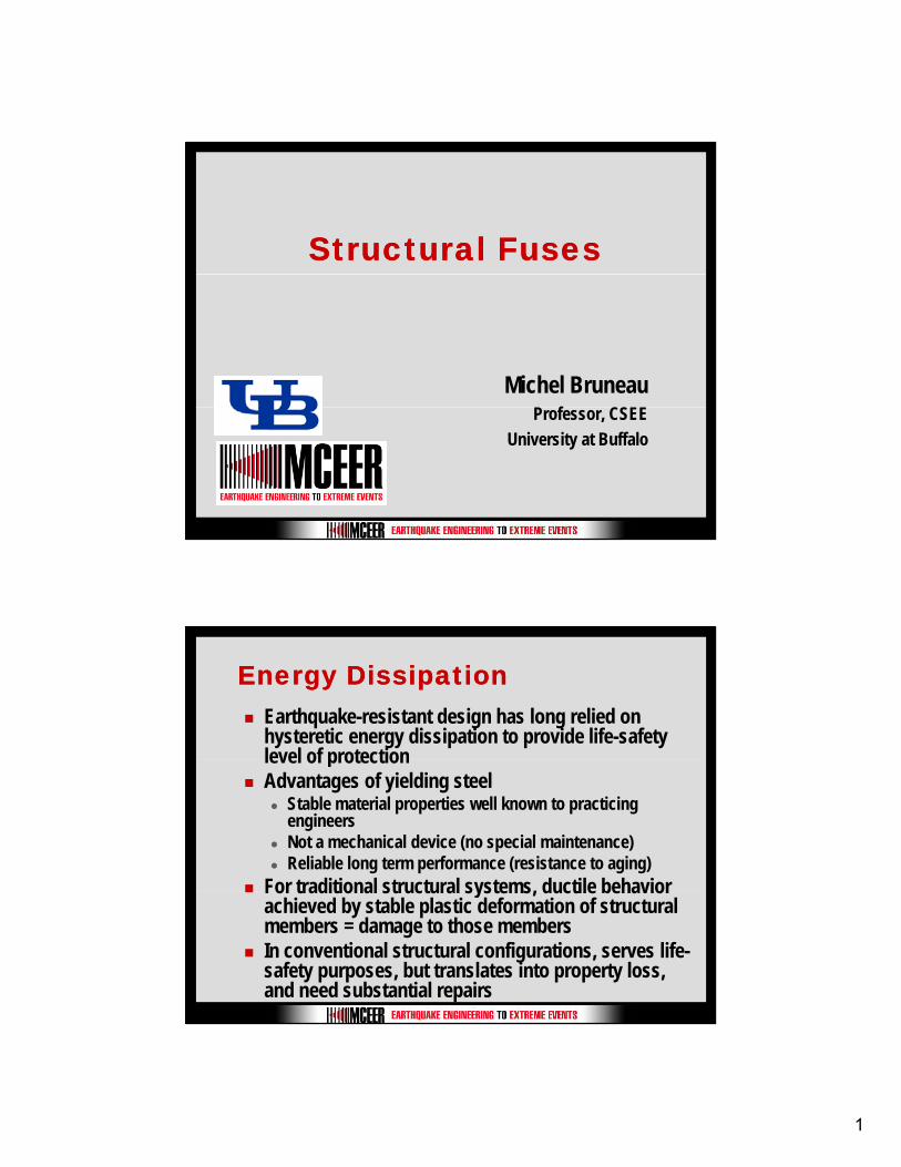
Structural FusesStructural Fuses
Michel Bruneauf CSProfessor, CSEE
University at Buffalo
Energy DissipationEnergy DissipationEarthquake-resistant design has long relied on hysteretic energy dissipation to provide life-safety level of protectionlevel of protectionAdvantages of yielding steel
Stable material properties well known to practicing engineersNot a mechanical device (no special maintenance)Reliable long term performance (resistance to aging)
For traditional structural systems, ductile behavior For traditional structural systems, ductile behavior achieved by stable plastic deformation of structural members = damage to those membersIn conventional structural configurations, serves life-safety purposes, but translates into property loss, and need substantial repairs
2
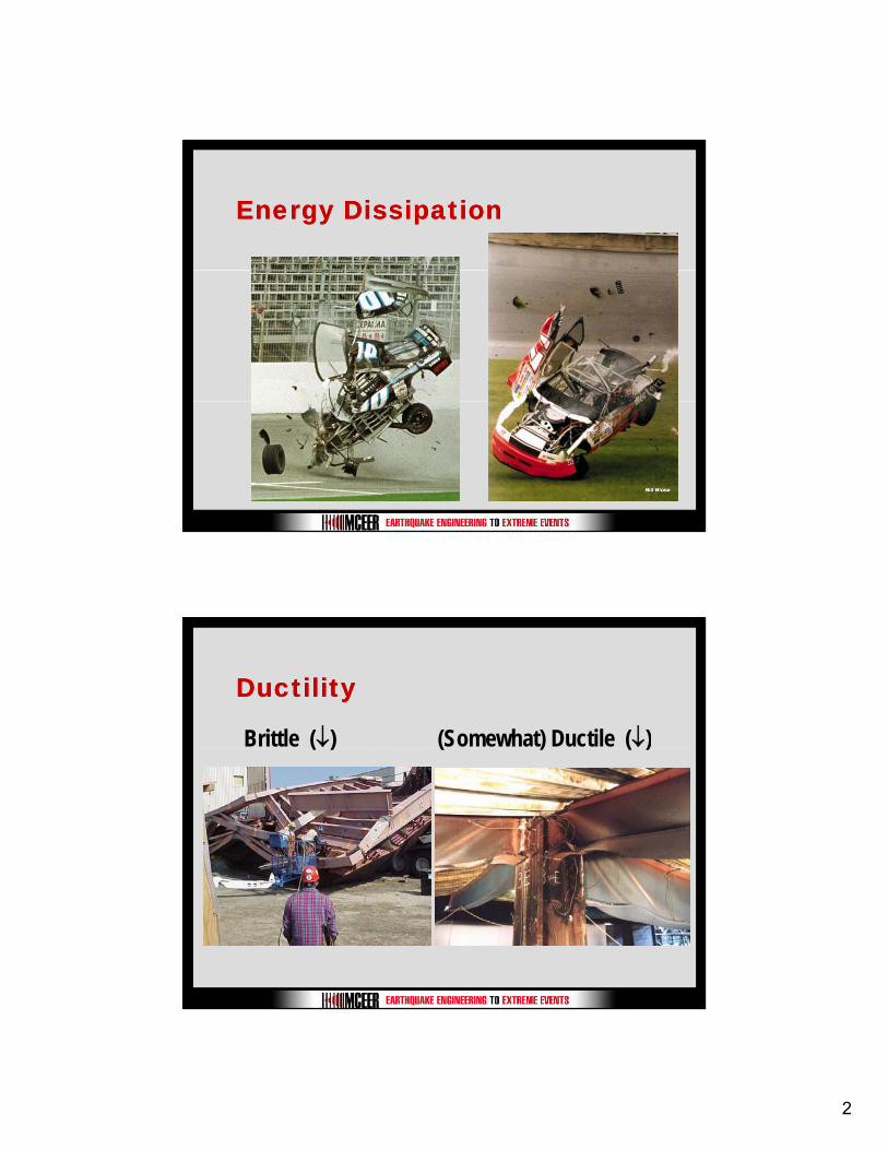
Energy DissipationEnergy Dissipation
DuctilityDuctility
Brittle (↓) (Somewhat) Ductile (↓)( ) ( ) ( )
3
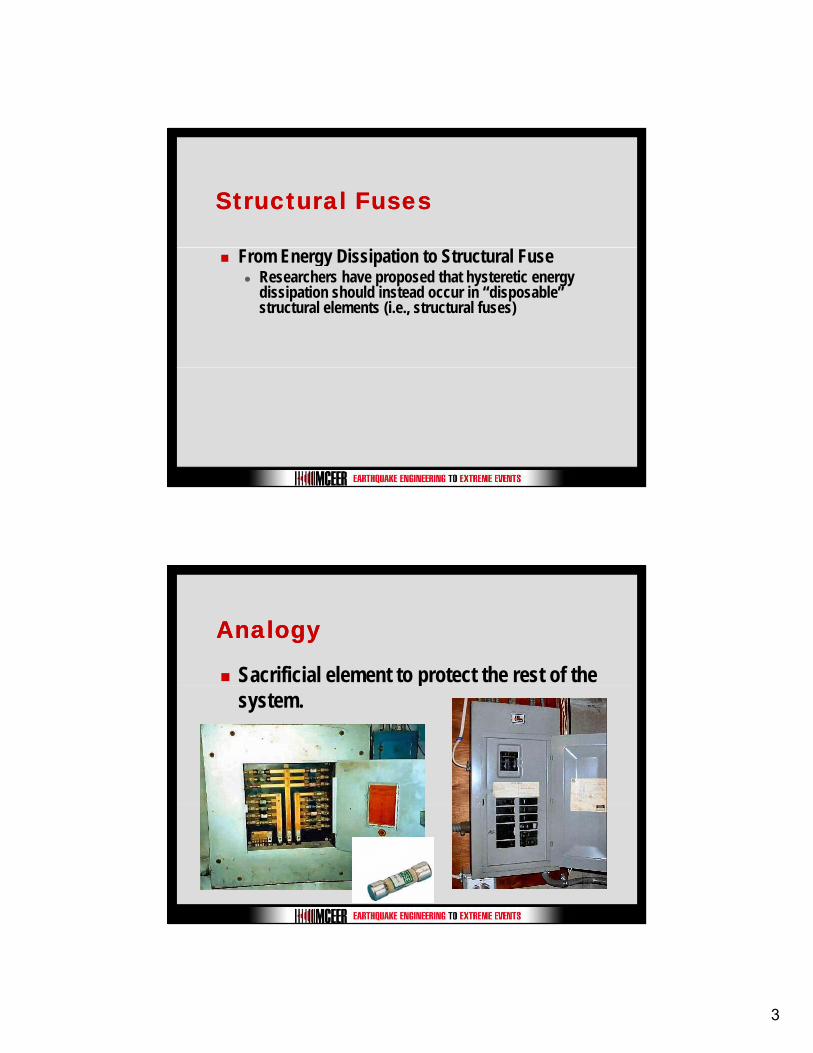
Structural FusesStructural Fuses
From Energy Dissipation to Structural FuseResearchers have proposed that hysteretic energy dissipation should instead occur in “disposable” structural elements (i.e., structural fuses)
AnalogyAnalogy
Sacrificial element to protect the rest of the psystem.
4
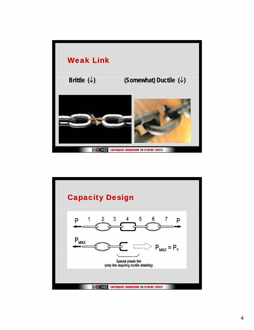
Weak LinkWeak Link
B i l (↓) (S h ) D il (↓)Brittle (↓) (Somewhat) Ductile (↓)
Capacity DesignCapacity Design
5
Eccentrically Braced Frames Eccentrically Braced Frames with Tubular Linkswith Tubular Links
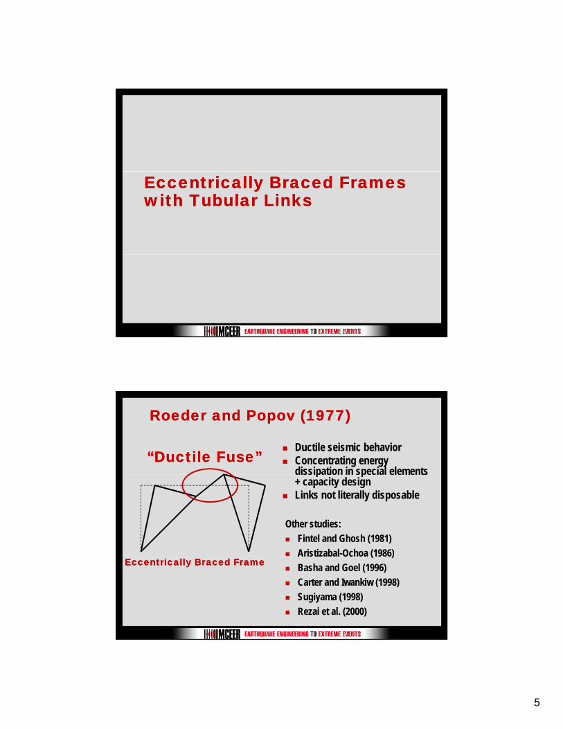
Roeder and Popov (1977)Roeder and Popov (1977)
Ductile seismic behaviorConcentrating energy dissipation in special elements
“Ductile Fuse”“Ductile Fuse”dissipation in special elements + capacity designLinks not literally disposable
Other studies:Fintel and Ghosh (1981)Aristizabal-Ochoa (1986)
Eccentrically Braced FrameEccentrically Braced Frame( )
Basha and Goel (1996)Carter and Iwankiw (1998)Sugiyama (1998)Rezai et al. (2000)
6
Eccentrically Braced FrameEccentrically Braced Frame
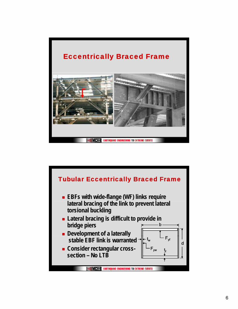
Tubular Eccentrically Braced FrameTubular Eccentrically Braced Frame
EBFs with wide-flange (WF) links require
bbb
lateral bracing of the link to prevent lateral torsional bucklingLateral bracing is difficult to provide in bridge piersDevelopment of a laterally
dtf
tw
Fyw
Fyfd
tf
tw
Fyw
Fyfd
tf
tw
Fyw
Fyf
p ystable EBF link is warrantedConsider rectangular cross-section – No LTB
7
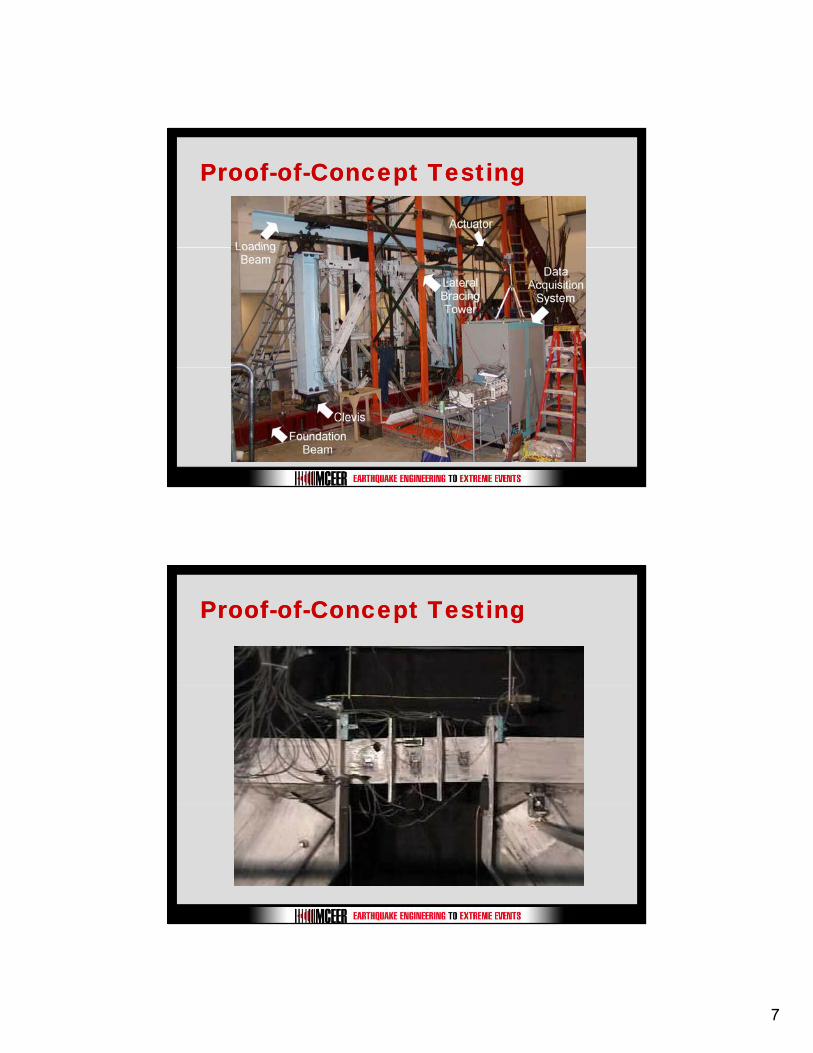
ProofProof--ofof--Concept TestingConcept Testing
ProofProof--ofof--Concept TestingConcept Testing
8
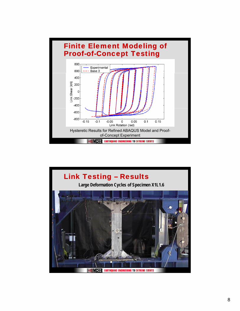
Finite Element Modeling of Finite Element Modeling of ProofProof--ofof--Concept TestingConcept Testing
Hysteretic Results for Refined ABAQUS Model and Proof-of-Concept Experiment
Link Testing Link Testing –– ResultsResultsLarge Deformation Cycles of Specimen X1L1.6
9
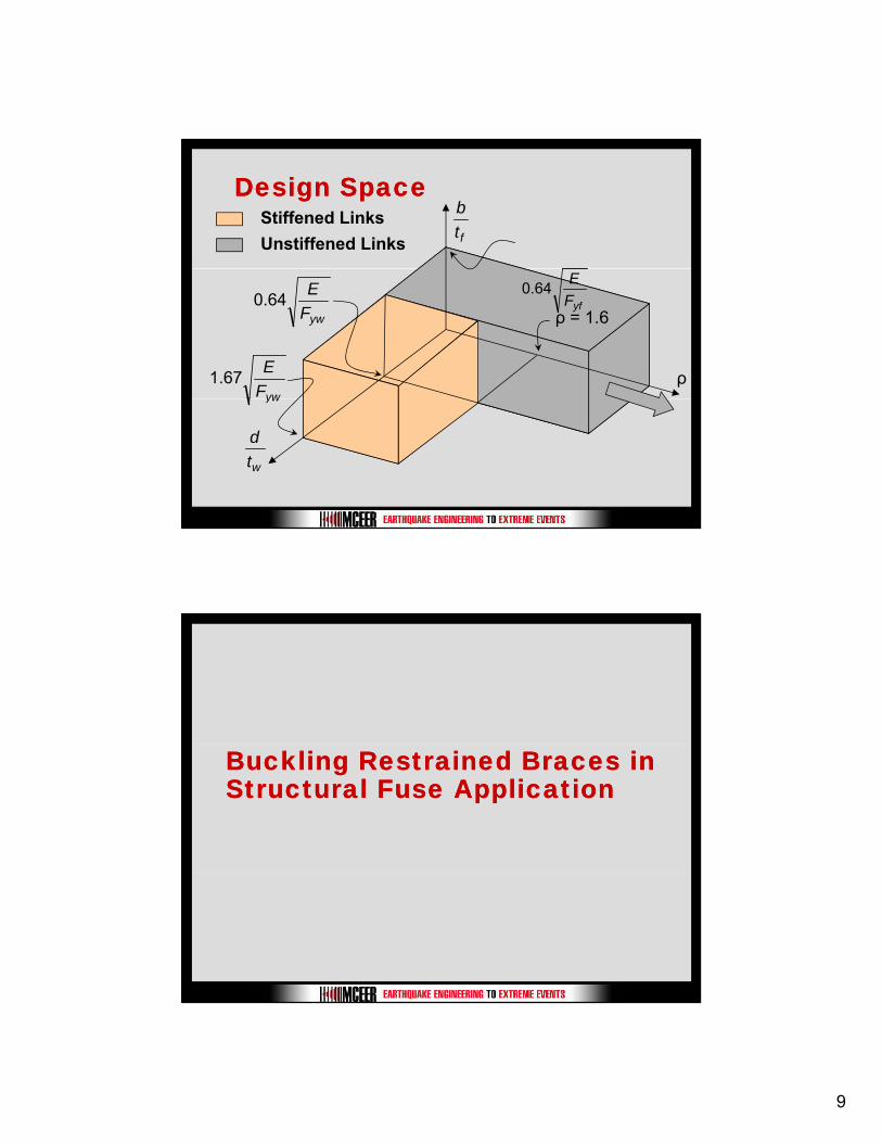
Design SpaceDesign SpaceStiffened LinksUnstiffened Links ft
b
ρ
ρ = 1.6yfFE0.64
ywFE1.67
ywFE0.64
yw
wtd
Buckling Restrained Braces in Buckling Restrained Braces in Structural Fuse ApplicationStructural Fuse Application
10
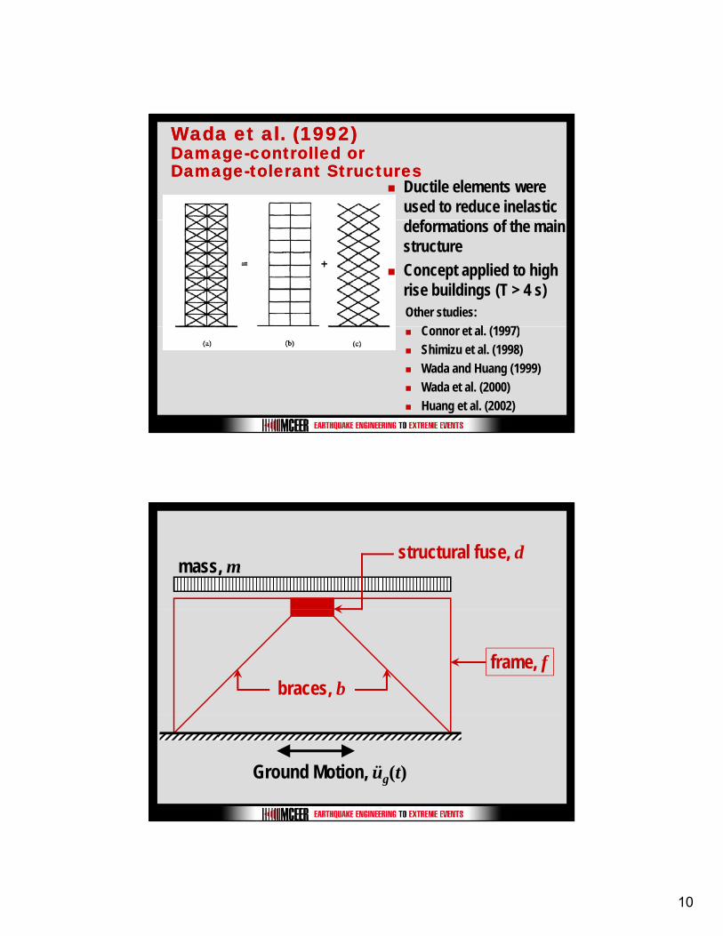
Wada et al. (1992)Wada et al. (1992)DamageDamage--controlled or controlled or DamageDamage--tolerant Structurestolerant Structures
Ductile elements were used to reduce inelastic
f f
Other studies:C t l (1997)
deformations of the main structureConcept applied to high rise buildings (T > 4 s)
Connor et al. (1997)Shimizu et al. (1998)Wada and Huang (1999)Wada et al. (2000)Huang et al. (2002)
mass, mstructural fuse, d
frame, fbraces, b
Ground Motion, üg(t)
11
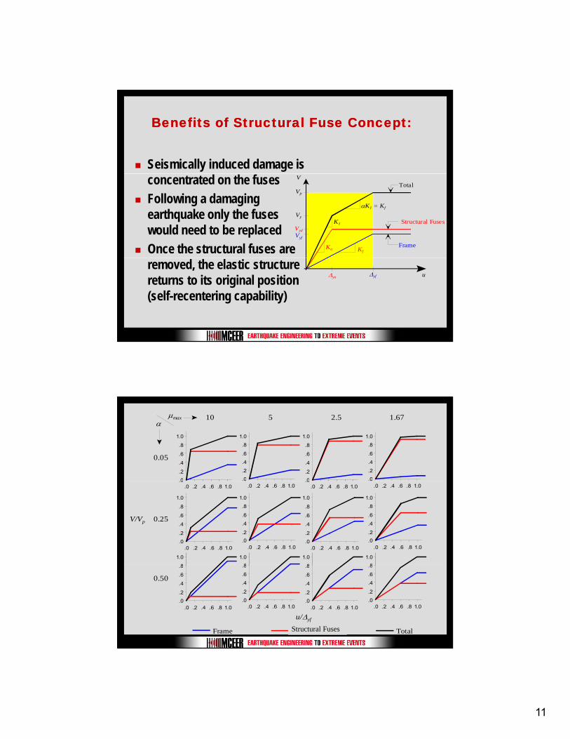
Benefits of Structural Fuse Concept:Benefits of Structural Fuse Concept:
Seismically induced damage is concentrated on the fusesFollowing a damaging earthquake only the fuses would need to be replacedOnce the structural fuses are Kf
Ka
K1
αK1 = Kf
Vyf
Vyd
Vy
Vp
V
Frame
Structural Fuses
Total
removed, the elastic structure returns to its original position (self-recentering capability)
Δya Δyf u
αμmax
0.05
0
.2
.4
.6
.8
1.0
.0
.2
.4
.6
.8
1.0
0
.2
.4
.6
.8
1.0
.0
.2
.4
.6
.8
1.0
10 5 2.5 1.67
0.25
.0.0 .2 .4 .6 .8 1.0
0.0 .2 .4 .6 .8 1.0
.0.0 .2 .4 .6 .8 1.0
.0
.2
.4
.6
.8
1.0
.0 .2 .4 .6 .8 1.0.0.2
.4
.6
.8
1.0
.0 .2 .4 .6 .8 1.0.0
.2
.4
.6
.8
1.0
.0 .2 .4 .6 .8 1.0
8
1.0
8
1.0
8
1.0
0.0 .2 .4 .6 .8 1.0
.0
.2
.4
.6
.8
1.0
.0 .2 .4 .6 .8 1.0
8
1.0
V/Vp
0.50
.0
.2
.4
.6
.8
.0 .2 .4 .6 .8 1.0.0
.2
.4
.6
.8
.0 .2 .4 .6 .8 1.0.0
.2
.4
.6
.8
.0 .2 .4 .6 .8 1.0.0
.2
.4
.6
.8
.0 .2 .4 .6 .8 1.0
Frame Damping System Total
u/Δyf
Structural Fuses
12
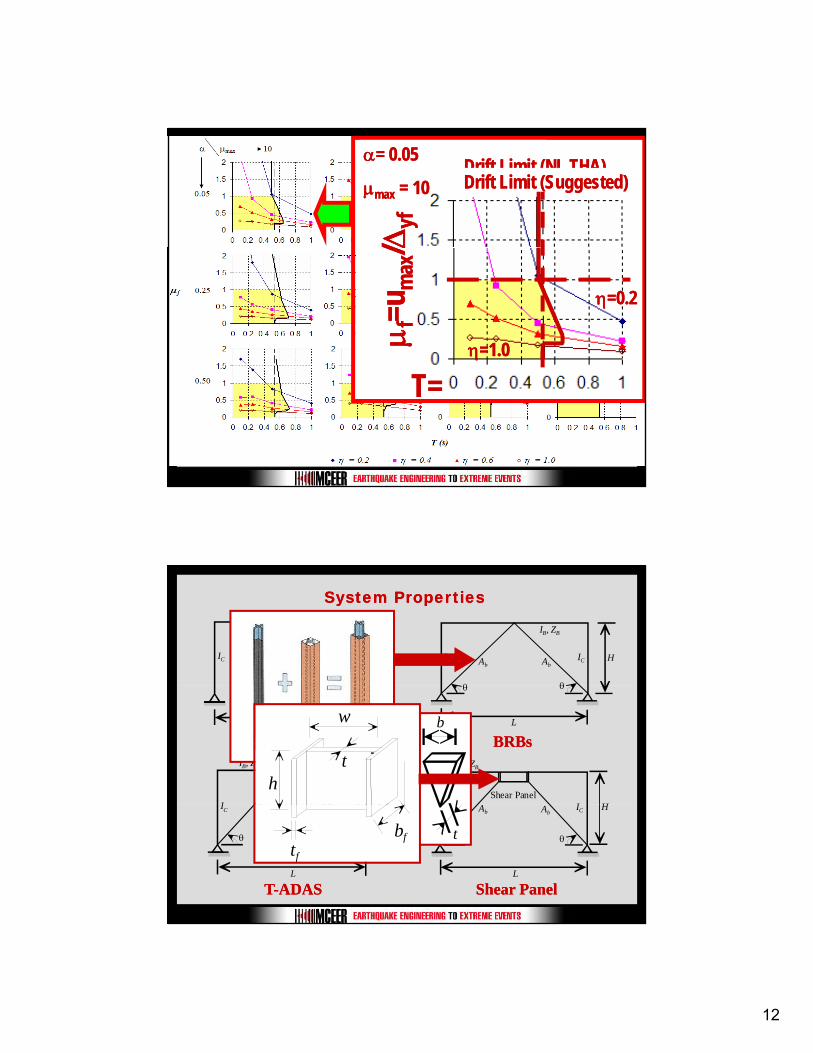
ΔΔyfyf
αα= 0.05= 0.05
μμmaxmax = 10= 10Drift Limit (NL THA)Drift Limit (NL THA)Drift Limit (Suggested)Drift Limit (Suggested)
μμ ff=u=u
max
max
//ΔΔ
ηη=0.2=0.2
ηη=1.0=1.0
T=T=
System PropertiesSystem Properties
IB, ZB
IC IC H
IB, ZB
IC HIC
θ θ
Ab Ab
L
Bare FrameBare FrameL
θ θ
BRBsBRBsIB, ZB
I I HA AN plates
IB, ZB
I I HShear Panel
h
b
h
w
t
IC IC
L
H
θ θ
Ab Ab
TT--ADASADAS
IC IC
L
H
θ θ
Ab Ab
Shear PanelShear Panel
tbftf
13
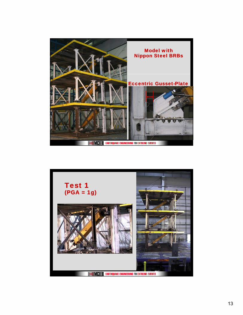
Model withModel withNippon Steel BRBsNippon Steel BRBs
Eccentric GussetEccentric Gusset--PlatePlate
Test 1 Test 1 (PGA = 1g)(PGA = 1g)
14
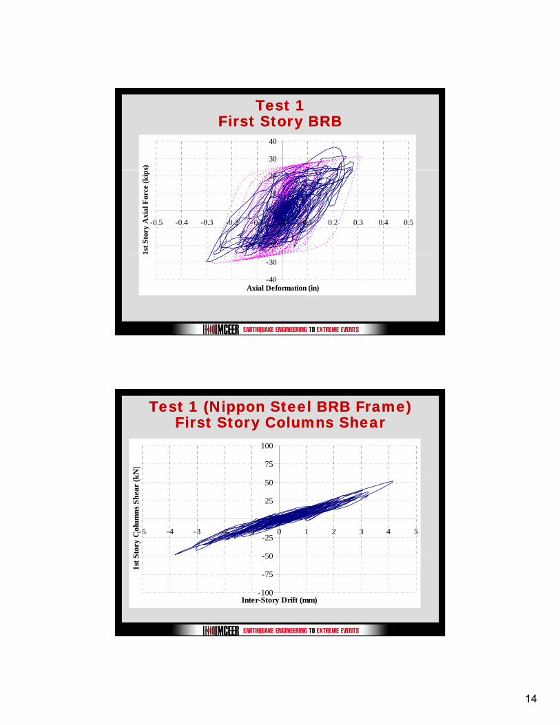
Test 1Test 1First Story BRBFirst Story BRB
30
40s)
-20
-10
0
10
20
-0.5 -0.4 -0.3 -0.2 -0.1 0 0.1 0.2 0.3 0.4 0.5
1st S
tory
Axi
al F
orce
(kip
-40
-30
Axial Deformation (in)
1
Test 1 (Nippon Steel BRB Frame)Test 1 (Nippon Steel BRB Frame)First Story Columns ShearFirst Story Columns Shear
75
100
N)
50
-25
0
25
50
-5 -4 -3 -2 -1 0 1 2 3 4 5
tory
Col
umns
She
ar (k
N
-100
-75
-50
Inter-Story Drift (mm)
1st S
15
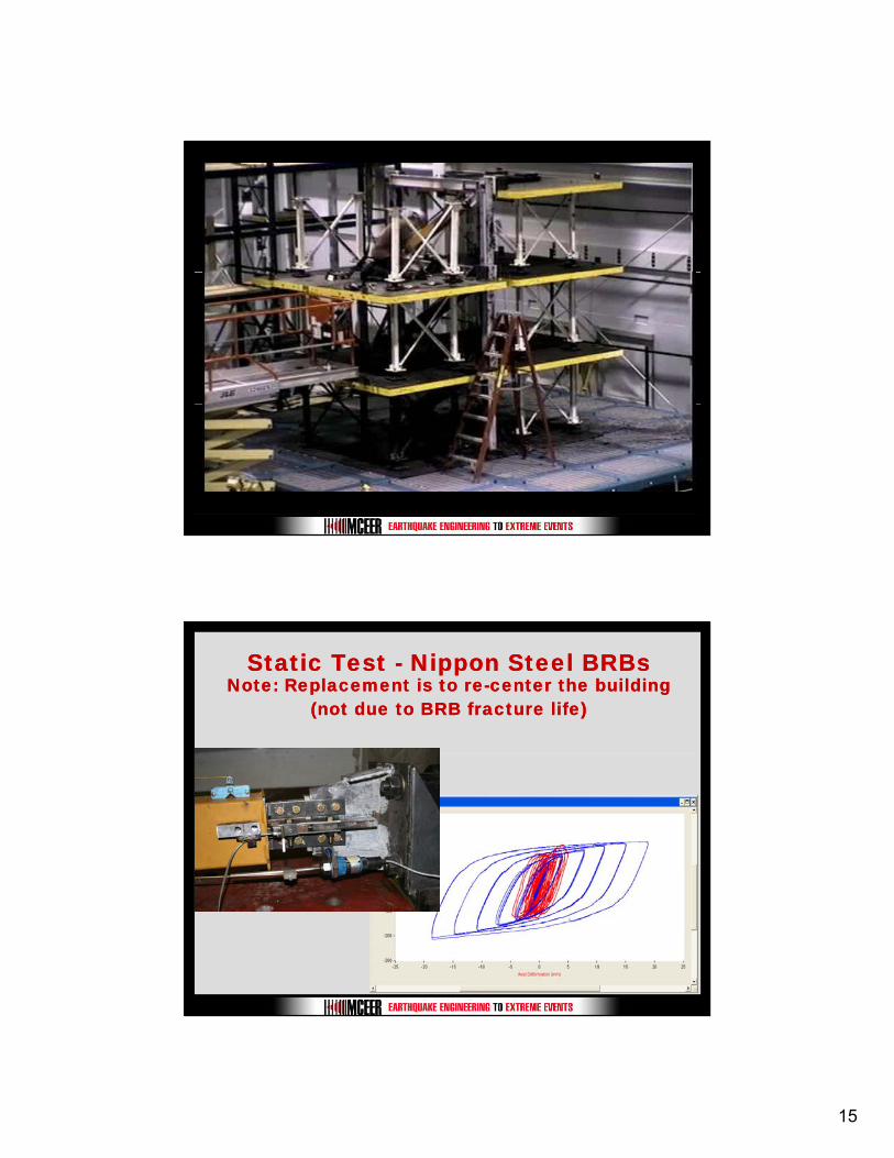
Static Test Static Test -- Nippon Steel BRBsNippon Steel BRBsNote: Replacement is to reNote: Replacement is to re--center the building center the building
(not due to BRB fracture life)(not due to BRB fracture life)
16
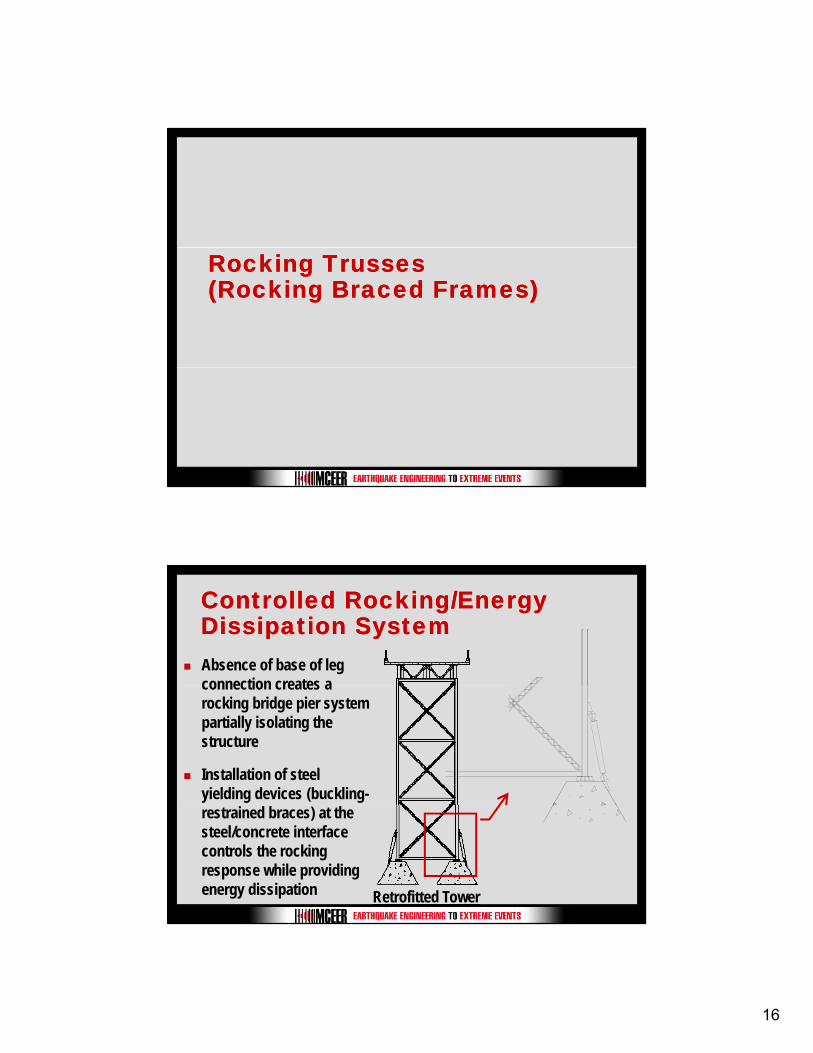
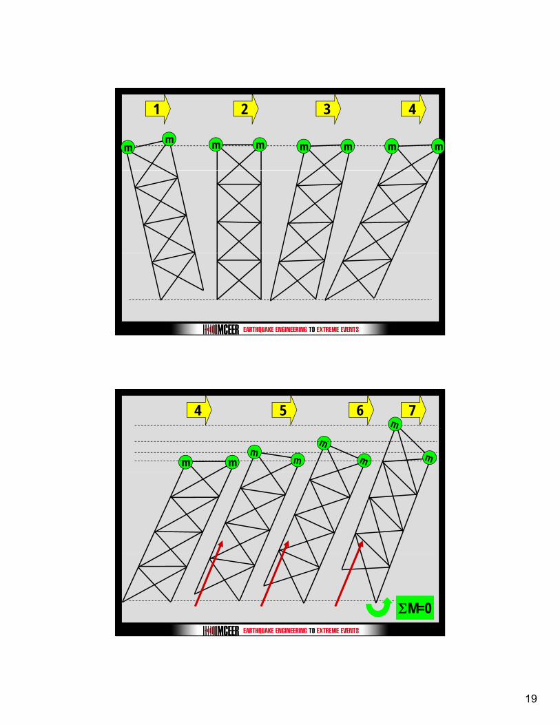
Rocking Trusses Rocking Trusses (Rocking Braced Frames)(Rocking Braced Frames)
Controlled Rocking/Energy Controlled Rocking/Energy Dissipation SystemDissipation SystemAbsence of base of leg connection creates a connection creates a rocking bridge pier system partially isolating the structure
Installation of steel yielding devices (buckling-
Retrofitted Tower
restrained braces) at the steel/concrete interface controls the rocking response while providing energy dissipation
17
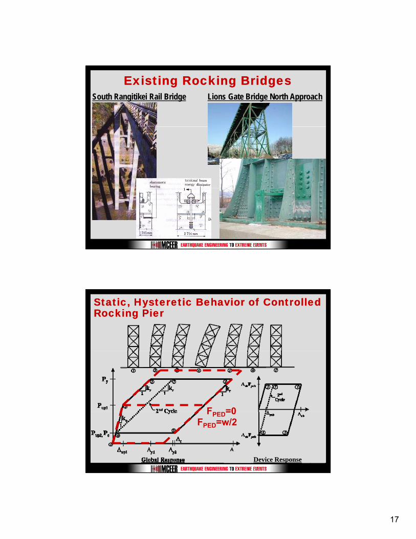
Existing Rocking BridgesExisting Rocking BridgesSouth Rangitikei Rail Bridge Lions Gate Bridge North Approach
Static, Hysteretic Behavior of Controlled Static, Hysteretic Behavior of Controlled Rocking PierRocking Pier
F =0
Device Response
FPED=0FPED=w/2
18
General Design Constraints for General Design Constraints for Controlled Rocking SystemControlled Rocking System
(1) Deck-level displacement limits need to be established on a case-by-case basis
Maintain pier stabilityBridge serviceability requirements
(2) Strains on buckling-restrained brace (uplifting displacements) need to be limited such that it behaves in a stable, reliable manner(3) Capacity Protection of existing, vulnerable resisting elements considering 3-components of excitation and dynamic forces developed during impact and uplift(4) Allow for self-centering of pier
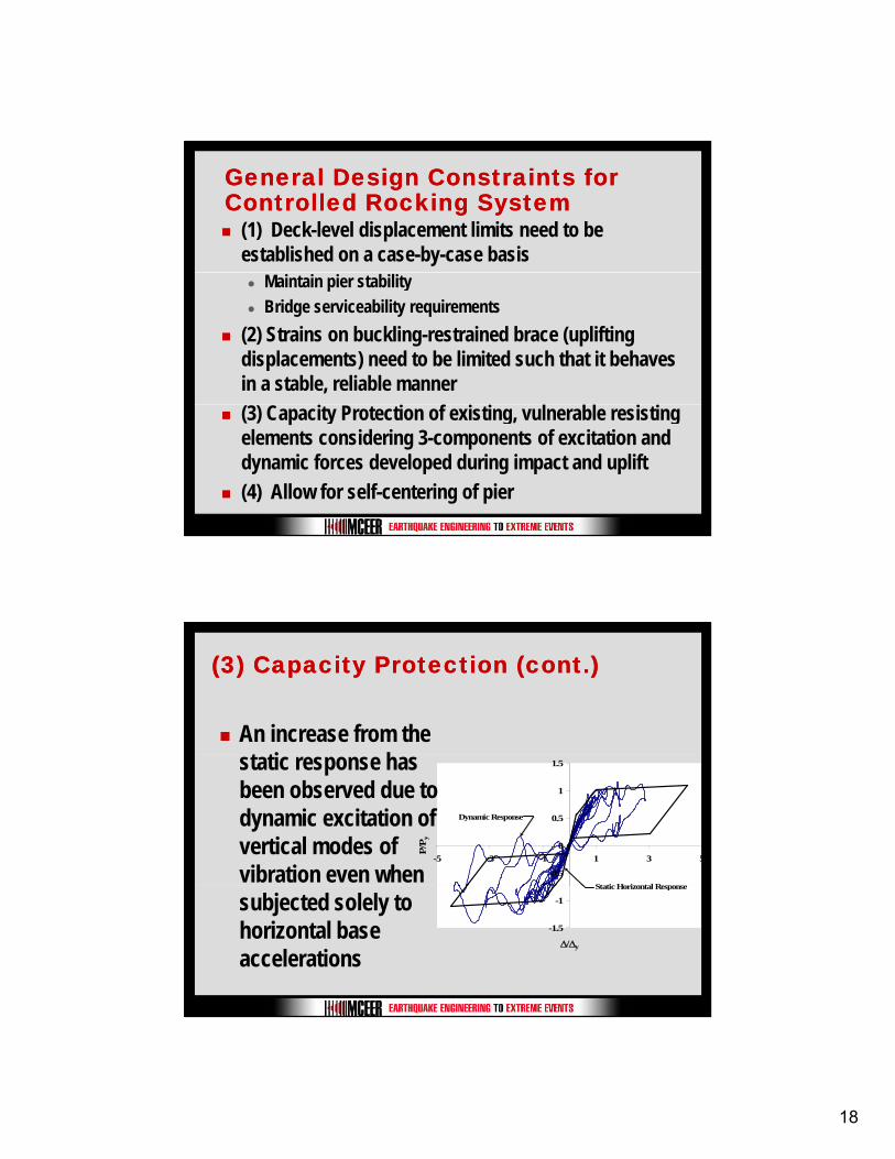
(3) Capacity Protection (cont.)(3) Capacity Protection (cont.)
An increase from the t ti h
-0.5
0
0.5
1
1.5
-5 -3 -1 1 3 5
P/P y
Static Horizontal Response
Dynamic Response
static response has been observed due to dynamic excitation of vertical modes of vibration even when
-1.5
-1
Δ/Δy
Static Horizontal Response
subjected solely to horizontal base accelerations
19
1
mm
2
mm
3
mm
4
mm
4 6
mm
5 7
ΣM=0
20
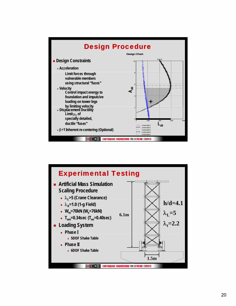
Acceleration⇒
Design ProcedureDesign Procedure
Design ConstraintsDesign Chart:
10h/d=4
VelocityControl impact energy to foundation and impulsive loading on tower legs by limiting velocity
⇒
Limit forces through vulnerable members using structural “fuses”
4
6
8
Aub
(in2
)A u
b
by limiting velocityDisplacement Ductility
Limit μL of specially detailed, ductile “fuses”
⇒
β<1⇒ Inherent re-centering (Optional)
0 100 200 300 4000
2
constraint1constraint2constraint3constraint4constraint5
Lub (in.)Lub
Experimental TestingExperimental TestingArtificial Mass Simulation Scaling Procedure
λL>5 (Crane Clearance)λL 5 (Crane Clearance)λA=1.0 (1-g Field)Wm=70kN (We=76kN)Tom=0.34sec (Toe=0.40sec)
Loading SystemPhase I
Δ
λL=5h/d=4.1
λt=2.26.1m
5DOF Shake TablePhase II
6DOF Shake Table
1.5m
21
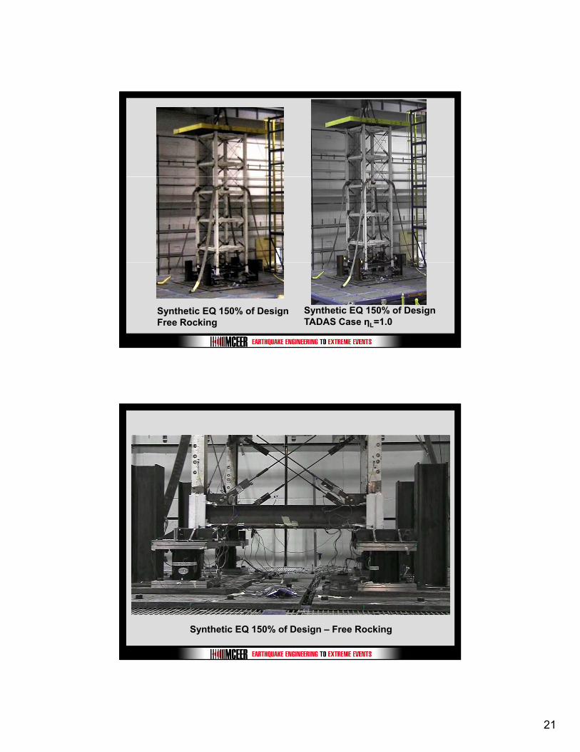
Synthetic EQ 150% of DesignFree Rocking
Synthetic EQ 150% of DesignTADAS Case ηL=1.0
Synthetic EQ 150% of Design – Free Rocking
22
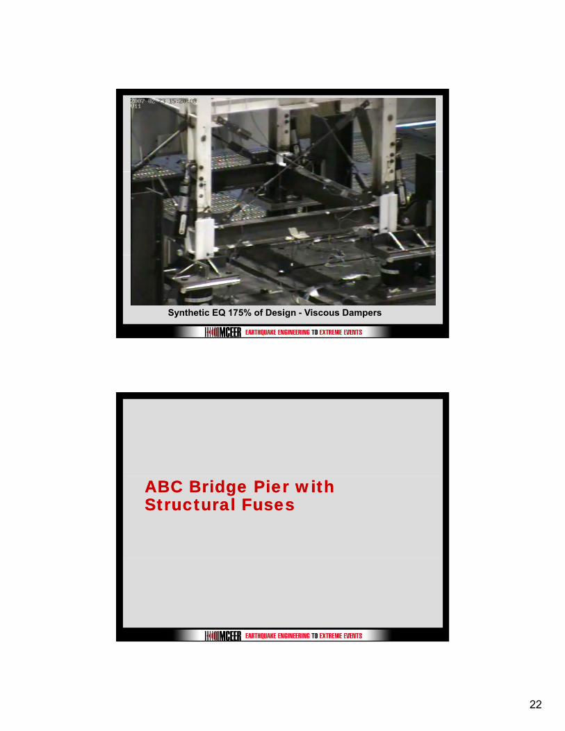
Synthetic EQ 175% of Design - Viscous Dampers
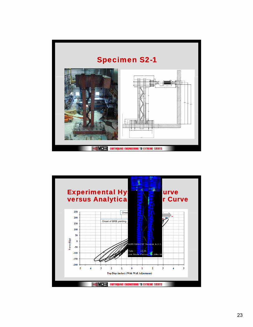
ABC Bridge Pier with ABC Bridge Pier with Structural FusesStructural Fuses
23
Specimen S2Specimen S2--11
Experimental Hysteretic Curve Experimental Hysteretic Curve versus Analytical Pushover Curveversus Analytical Pushover Curve
Onset of Column yielding
Onset of BRB yielding
Onset of Column yielding
24
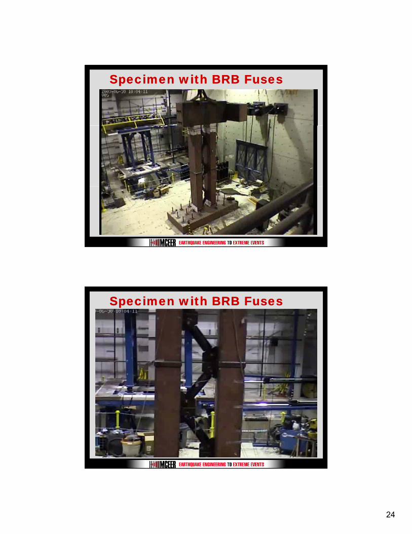
Specimen with BRB FusesSpecimen with BRB Fuses
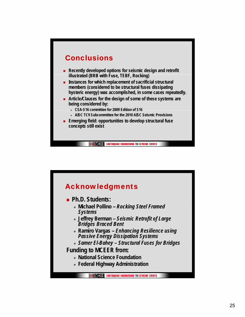
Specimen with BRB FusesSpecimen with BRB Fuses
25
ConclusionsConclusionsRecently developed options for seismic design and retrofit ill t t d (BRB ith F TEBF R ki )illustrated (BRB with Fuse, TEBF, Rocking)Instances for which replacement of sacrificial structural members (considered to be structural fuses dissipating hysteric energy) was accomplished, in some cases repeatedly. Article/Clauses for the design of some of these systems are being considered by:
CSA-S16 committee for 2009 Edition of S16CSA S16 committee for 2009 Edition of S16AISC TC9 Subcommittee for the 2010 AISC Seismic Provisions
Emerging field: opportunities to develop structural fuse concepts still exist
AcknowledgmentsAcknowledgments
Ph.D. Students: Michael Pollino Rocking Steel Framed Michael Pollino – Rocking Steel Framed SystemsJeffrey Berman – Seismic Retrofit of Large Bridges Braced BentRamiro Vargas – Enhancing Resilience using Passive Energy Dissipation SystemsSamer El Bahey Structural Fuses for BridgesSamer El-Bahey – Structural Fuses for Bridges
Funding to MCEER from:National Science Foundation Federal Highway Administration

26
Thank you!Thank you!
Questions?Questions?