Embed Size (px)
Citation preview
CIN – U40102GJ2003SGC042906,GST No.-24AAACU6551F1Z1
TENDER NOTICE No:-UGVCL/PROJECT/UKARDI/DEFENCE PARK/77
Tech. Spec. Dist. Transformer
Regd. & Corporate Office: Visnagar Road, MEHSANA – 384 001 (North Gujarat) Page No.:- 1 Telephone: (02762) 222080-81 Fax: (02762) 223574 Website: www.ugvcl.com Signature of Bidder e-mail: [email protected]
TECHNICAL SPECIFICATION FOR 11/0.433kV DISTRIBUTION TRANSFORMER
1.0 SCOPE:
As per the Electrical Transformer (Quality Control) Order, 2014, it is mandatory that No Electrical Transformers shall be manufacture or store for sale, sell or distribute which do not confirm to the specified standard and do not bear standard Mark of the Bureau. Moreover, as per the Guidelines of Bureau of Energy Efficiency (BEE), labeling of distribution transformer is mandatory & cannot be sold in the market without star label. Accordingly, the bidder shall have to submit valid BIS license of the quoted item or higher as per approved scheme of BIS and star rating certificate from BEE for 16 KVA to 500 KVA Transformers. This specification covers, engineering, manufacture, assembly, stage testing, and inspection and testing before supply and delivery at site of mineral oil-immersed, natural air-cooled, outdoor type, double-wound 3 phase 11/0.433 -0.250 KV Distribution Transformers for outdoor use in power distribution systems with nominal system voltages of following types and ratings:
Three Phase ratings lower than 63 KVA both non-sealed type and sealed type. (REF: IS 1180 PART-1 2014, 3.2&3.3).
Three phase ratings higher than and including63 KVA, non-sealed type. (REF: IS 1180 PART-1 2014, 3.2&16).
Single phase ratings 5 KVA sealed type. 1.1 It is not the intent to specify completely herein all the details of the design and
construction of equipment. However the equipment shall conform in all respects to high standards of engineering, design and workmanship and shall be capable of performing in continuous commercial operation up to the Bidder‘s guarantee, in a manner acceptable to the purchaser, who will interpret the meanings of drawings and specification and shall have the power to reject/accept any work or material which, in his judgment is there or not in accordance therewith. The offered equipment shall be complete with all components necessary for their effective and trouble free operation. Such, components shall be deemed to be within the scope of Bidder‘s supply irrespective of whether those are specifically brought out in this specification and / or the commercial order or not.
1.2 The transformer and accessories shall be designed to facilitate operation, inspection, maintenance and repairs. The design shall incorporate every precaution and provision for the safety of equipment as well as staff engaged in operation and maintenance of equipment.
1.3 All outdoor apparatus, including bushing insulators with their mountings, shall be designed so as to avoid any accumulation of water.
1.4 STANDARD RATINGS: The Standard Ratings shall be 5 KVA, 10 KVA, 16 KVA, 25 KVA, 63 KVA, 100 KVA, 200 KVA and 500 KVA.

CIN – U40102GJ2003SGC042906,GST No.-24AAACU6551F1Z1
TENDER NOTICE No:-UGVCL/PROJECT/UKARDI/DEFENCE PARK/77
Tech. Spec. Dist. Transformer
Regd. & Corporate Office: Visnagar Road, MEHSANA – 384 001 (North Gujarat) Page No.:- 2 Telephone: (02762) 222080-81 Fax: (02762) 223574 Website: www.ugvcl.com Signature of Bidder e-mail: [email protected]
2.0 STANDARDS: 2.1 The materials shall conform in all respects to the relevant Indian / International
Standard Specification, with latest amendments thereof, some of them are listed below:
Indian Standard Title International & Internationally recognized standard
ISS – 1180 / Part-I/ 2014 with latest amendments
Outdoor/Indoor type Oil immersed distribution Transformer up to and including 2500 kVA, 33KV Specifications Mineral Oil Immersed
ISS - 16585:2016 Magnetic materials - specifications for individual materials - Fe based amorphous strip delivered in the semi processed state
5484 Specifications for Aluminum wire rods ASTM B-233
649 Testing of Steel sheet and strips for magnetic circuits
191: 2007 Copper
335 : 1993 New insulating oils
BS 148, D-1473, D-1533- 1934 IEC Pub 296-1969
554 : 1999 Pipe threads where pressure-tight joints are made on the threads — Dimensions, tolerances and designation
1576 : 1992 Solid pressboard for electrical purpose IEC 641
1608 : 2005 Mechanical testing of metals — Tensile testing
1747 : 1972 Nitrogen
1885 (Part 38) :1993 Electro technical vocabulary: Part 38 Power transformers and reactors
1897 : 2008 Copper strip for electrical purpose
2026 Power transformers : IEC 76
(Part 1) : 2011 General
(Part 2) : 2010 Temperature rise
(Part 3) : 2009 Insulation levels, dielectric tests and external clearances in air
(Part 5) : 2011 Ability to withstand short circuit
(Part 8) : 2009 Application guide
(Part 10) : 2009 Determination of sound levels
2099 : 1986 Bushings for alternative voltages above 1000 volts
3024 : 2006 Grain oriented electrical steel sheets and strips
3347 Dimensions for porcelain transformer bushings for use in lightly polluted atmospheres
DIN 42531,23,3
(Part 1/Sec 1) : 1979 Up to and including 1 kV, Section 1 Porcelain

CIN – U40102GJ2003SGC042906,GST No.-24AAACU6551F1Z1
TENDER NOTICE No:-UGVCL/PROJECT/UKARDI/DEFENCE PARK/77
Tech. Spec. Dist. Transformer
Regd. & Corporate Office: Visnagar Road, MEHSANA – 384 001 (North Gujarat) Page No.:- 3 Telephone: (02762) 222080-81 Fax: (02762) 223574 Website: www.ugvcl.com Signature of Bidder e-mail: [email protected]
Indian Standard Title International & Internationally recognized standard
parts
(Part 1/Sec 2) : 1979 Up to and including 1 kV, Section 2 Metal parts
(Part 2/Sec 1) : 1979 3.6 kV Bushings, Section 1 Porcelain parts
(Part 2/Sec 2) : 1979 3.6 kV Bushings, Section 2 Metal parts
(Part 3/Sec 1) : 1988 17.5 kV Bushings, Section 1 Porcelain parts
(Part 3/Sec 2) : 1988 17.5 kV Bushings, Section 2 Metal parts
8603:2008 Dimensions for porcelain transformer bushings for use in heavily polluted atmospheres,12/17.5 KV,24 KV and 36 KV
ISS 5/1961 Specification for colors for ready mixed paints.
ISS- 6600/1972 Guide for loading of oil Immersed Transformers IEC 76
ISS-10028 Installation, Maintenance of Transformers
ISS-4257 Dimension for clamping arrangement for bushings (for porcelain and metal parts)
ISS- 6160 Rectangular conductors for electrical machine
ISS- 3401 Silica gel
ISS-1866 Code of practice for maintenance & supervision of Mineral insulating oil in equipment
3639 : 1966 Fittings and accessories for power transformers
4253 (Part 2) : 2008 Cork composition sheet: Part 2 Cork and rubber
6162 Paper-covered aluminum conductors
(Part 1) : 1971 Round conductors
(Part 2) : 1971 Rectangular conductors
7404 (Part1) : 1991 Paper covered copper conductors: Part 1 Round conductors
7421 : 1988 Porcelain bushings for alternating voltages up to and including 1 000 V
8999 : 2003 Pipe threads where pressure tight joints are made on the threads — Verification by means of limit gauges
9335(Part 1) : 1979 Cellulosic papers for electrical purposes: Definitions and general requirements
IEC 554
(Part 2) : 1998 Methods of test
(Part 3/Sec 1) : 1984
Specifications for individual materials, Section 1 General purposes electrical paper
(Part 3/ Sec 3) :1984 Specifications for individual materials, Section 3 Crepe paper
(Part 3/ Sec 5) : 1985 Specifications for individual materials, Section 5 Special papers
11149 : 1984 Specification for rubber gaskets
12444 : 1988 Continuously cast and rolled electrolytic copper wire rods for electrical Conductors
ASTM B-49
CIN – U40102GJ2003SGC042906,GST No.-24AAACU6551F1Z1
TENDER NOTICE No:-UGVCL/PROJECT/UKARDI/DEFENCE PARK/77
Tech. Spec. Dist. Transformer
Regd. & Corporate Office: Visnagar Road, MEHSANA – 384 001 (North Gujarat) Page No.:- 4 Telephone: (02762) 222080-81 Fax: (02762) 223574 Website: www.ugvcl.com Signature of Bidder e-mail: [email protected]
Indian Standard Title International & Internationally recognized standard
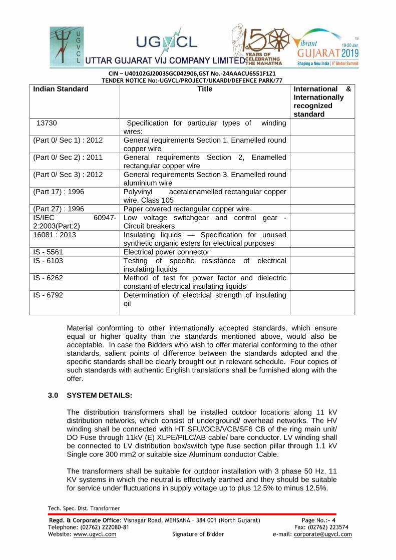
13730 Specification for particular types of winding wires:
(Part 0/ Sec 1) : 2012 General requirements Section 1, Enamelled round copper wire
(Part 0/ Sec 2) : 2011 General requirements Section 2, Enamelled rectangular copper wire
(Part 0/ Sec 3) : 2012 General requirements Section 3, Enamelled round aluminium wire
(Part 17) : 1996 Polyvinyl acetalenamelled rectangular copper wire, Class 105
(Part 27) : 1996 Paper covered rectangular copper wire
IS/IEC 60947-2:2003(Part:2)
Low voltage switchgear and control gear - Circuit breakers
16081 : 2013 Insulating liquids — Specification for unused synthetic organic esters for electrical purposes
IS - 5561 Electrical power connector
IS - 6103
Testing of specific resistance of electrical insulating liquids
IS - 6262
Method of test for power factor and dielectric constant of electrical insulating liquids
IS - 6792 Determination of electrical strength of insulating oil
Material conforming to other internationally accepted standards, which ensure equal or higher quality than the standards mentioned above, would also be acceptable. In case the Bidders who wish to offer material conforming to the other standards, salient points of difference between the standards adopted and the specific standards shall be clearly brought out in relevant schedule. Four copies of such standards with authentic English translations shall be furnished along with the offer.
3.0 SYSTEM DETAILS:
The distribution transformers shall be installed outdoor locations along 11 kV distribution networks, which consist of underground/ overhead networks. The HV winding shall be connected with HT SFU/OCB/VCB/SF6 CB of the ring main unit/ DO Fuse through 11kV (E) XLPE/PILC/AB cable/ bare conductor. LV winding shall be connected to LV distribution box/switch type fuse section pillar through 1.1 kV Single core 300 mm2 or suitable size Aluminum conductor Cable. The transformers shall be suitable for outdoor installation with 3 phase 50 Hz, 11 KV systems in which the neutral is effectively earthed and they should be suitable for service under fluctuations in supply voltage up to plus 12.5% to minus 12.5%.

CIN – U40102GJ2003SGC042906,GST No.-24AAACU6551F1Z1
TENDER NOTICE No:-UGVCL/PROJECT/UKARDI/DEFENCE PARK/77
Tech. Spec. Dist. Transformer
Regd. & Corporate Office: Visnagar Road, MEHSANA – 384 001 (North Gujarat) Page No.:- 5 Telephone: (02762) 222080-81 Fax: (02762) 223574 Website: www.ugvcl.com Signature of Bidder e-mail: [email protected]
3.1 SERVICE CONDITIONS: The Distribution Transformers to be supplied against this Specification shall be suitable for satisfactory continuous operation under the following climatic conditions as per IS 2026 (Part - I) Latest Revision.
Sr. No
Parameters Values
1. Location At various locations in Gujarat
2. Max ambient air temperature (Degree C) 50
3. Min. ambient air temperature (Degree C) 0
4. Max average daily ambient air temperature (Degree C)
45
5. Max. yearly weighed average ambient temperature (Degree C)
40
6. Max. altitude above mean sea level (meter) 1000
7. Maximum relative humidity (%age) 0 to 100%
8. Average thunder storms (days/ Annum) 15
9. Average rainy days (days/ Annum) 90
10. Average annual rain fall (mili meter) 800/ 900 mm
11. Number of months of tropical monsoon (months)
3 Months
The equipment shall be for use in moderately hot and humid tropical climate, conducive to rust and fungus growth.

CIN – U40102GJ2003SGC042906,GST No.-24AAACU6551F1Z1
TENDER NOTICE No:-UGVCL/PROJECT/UKARDI/DEFENCE PARK/77
Tech. Spec. Dist. Transformer
Regd. & Corporate Office: Visnagar Road, MEHSANA – 384 001 (North Gujarat) Page No.:- 6 Telephone: (02762) 222080-81 Fax: (02762) 223574 Website: www.ugvcl.com Signature of Bidder e-mail: [email protected]
4.0 PRINCIPAL PARAMETERS:
Sl. No.
Item Specification
1. Continuous rated capacity 5 KVA 10 KVA 16 KVA 25 KVA 63 KVA 100 KVA 200 KVA 500 KVA
2. System voltage (max.) 12 kV (Line to Line)
12 kV 12 kV 12 kV 12 kV 12 kV 12 kV 12 kV
3. Rated voltage HV 11 kV 11 kV 11 kV 11 kV 11 kV 11 kV 11 kV 11 kV
4. Rated voltage LV 250 V 433-250 V 433-250 V 433-250 V 433-250 V 433-250 V 433-250 V 433-250 V
5. Line current HV 0.454 A 0.525 A 0.84 A 1.31 A 3.306 A 5.25 A 10.50 A 26.25 A
6. Line current LV 20.0 A 13.3 A 21.33 A 33.33 A 84.0 A 133.0 A 266.0 A 665.0 A
7. Frequency 50 c/s +/- 5%
50 c/s +/- 5%
50 c/s +/- 5%
50 c/s +/- 5%
50 c/s +/- 5%
50 c/s +/- 5%
50 c/s +/- 5%
50 c/s +/- 5%
8. No. of Phases Single Three Three Three Three Three Three Three
9. Connection HV Single Delta Delta Delta Delta Delta Delta Delta
10. Connection LV Individual Star (Neutral brought out)
Star (Neutral brought out)
Star (Neutral brought out)
Star (Neutral brought out)
Star (Neutral brought out)
Star (Neutral brought out)
Star (Neutral brought out)
11. Vector group -- Dyn-11 Dyn-11 Dyn-11 Dyn-11 Dyn-11 Dyn-11 Dyn-11
12. Type of cooling
ONAN ONAN ONAN ONAN ONAN ONAN ONAN ONAN
13. Tap changing arrangement
Not applicable
Not applicable
Not applicable
Not applicable
Not applicable
Not applicable
-7.5 % to +10% in steps of 2.5 %
-7.5 % to +10% in steps of 2.5 %

CIN – U40102GJ2003SGC042906,GST No.-24AAACU6551F1Z1
TENDER NOTICE No:-UGVCL/PROJECT/UKARDI/DEFENCE PARK/77
Tech. Spec. Dist. Transformer
Regd. & Corporate Office: Visnagar Road, MEHSANA – 384 001 (North Gujarat) Page No.:- 7 Telephone: (02762) 222080-81 Fax: (02762) 223574 Website: www.ugvcl.com Signature of Bidder e-mail: [email protected]
Sl. No.
Item Specification
14. Noise level at rated voltage and frequency
48db 48 db 48 db 48 db 51db 51db 55 db 56 db
15. Permissible temperature rise over ambient i) Of top oil measured by thermometer ii) Of winding measuredby resistance
30Deg.C 35Deg.C
35 Deg.C 40 Deg.C
35 Deg.C 40 Deg.C
35 Deg.C 40 Deg.C
35 Deg.C 40 Deg.C
35 Deg.C 40 Deg.C
35 Deg.C 40 Deg.C
35Deg.C 40Deg.C
16 Minimum clearances in air of bushing terminals with connectors fitted in mm.
HV Phase to Phase 255 255 255 255 255 255 255 255
HV Phase to Earth 205 205 205 205 205 205 205 205
LV Phase to Phase -- 75 75 75 75 75 75 75
LV Phase/ Neutral to Earth
75 55 55 55 55 55 55 55
17 Basic Insulation Level (Minimum)
95 KV 95 KV 95 KV 95 KV 95 KV 95 KV 95 KV 95 KV

CIN – U40102GJ2003SGC042906,GST No.-24AAACU6551F1Z1
TENDER NOTICE No:-UGVCL/PROJECT/UKARDI/DEFENCE PARK/77
Regd. & Corporate Office: Visnagar Road, MEHSANA – 384 001 (North Gujarat) Page No.:- 8 Telephone: (02762) 222080-81 Fax: (02762) 223574 Website: www.ugvcl.com Signature of Bidder
5.0 TECHNICAL REQUIREMENTS : 5.1 CORE: A. A. CRGO:
i. Transformer core shall be stacked core type, shell type or with wound core construction using new and high quality CRGO core with heat resistant insulating coating. The core shall be of NEW/Fresh high grade cold rolled grain oriented annealed lamination core having low loss and good grain properties, coated with hot oil proof insulation, bolted together and to the frames firmly to prevent vibration or noise. The complete design of core must ensure permanency of the core losses with continuous working of the transformers. The core shall be stress relieved by annealing under inert atmosphere if required. The complete design of core must ensure permanency of the core loss with continuous working of the transformers. The value of the maximum flux density allowed in the design and grade of lamination used shall be clearly stated in the offer.
ii. CORE CLAMPING : 1. MS channel shall be used on top and bottom. 2. Core Channel on LV side to be reinforced at equidistance, if holes / cutting is
done for LT lead in order to avoid bending of channel. 3. MS Channels shall be painted with hot oil-resistant paint. 4. The transformers core shall be suitable for over fluxing (due to combined
effect of voltage and frequency) up to 112.5% without injurious heating at full load conditions and shall not get saturated. The Bidder shall furnish necessary design data in support of this situation.
5. The nominal flux density in any part of the core shall not exceed 1.69 Tesla at 100% rated voltage and frequency and the maximum flux density in any part of the core and yoke at rated voltage and frequency shall be such that the flux density with 112.5 % combined voltage and frequency variation from rated voltage and frequency shall not exceed 1.9Tesla. (REF IS 1180 PART-1 2014 6.9.1&7.9.1)
NOTE: The design calculations in support of flux density shall be furnished by the manufacturer.
6. No load current shall not exceed the below mentioned percentage of full load
current by energizing the transformer on secondary side.
Particulars Up to 200KVA
Above 200KVA
i. At rated voltage and frequency on the secondary. 3% 2%
ii. At voltage by 112.5% of rated voltage but at rated frequency. 6% 5%
7. Test for magnetic balance by connecting the LV phase by phase to rated phase voltage and measurement of un, vn, wn voltage will be carried out.
8. Clamping and Tie-rods shall be made from HT Bright Bars steel & shall be painted with hot oil resistant paint.(IS 1180 table 12)
B. AMORPHOUS :
i. The core shall be high quality amorphous ribbons having very low loss formed into wound cores of rectangular shape, bolted together to the frames firmly to prevent vibration or noise. The complete design of core must ensure permanency of the core loss with continuous working of the transformers. The value of the flux density allowed in the design shall be clearly stated in the offer. Curve showing the

CIN – U40102GJ2003SGC042906,GST No.-24AAACU6551F1Z1
TENDER NOTICE No:-UGVCL/PROJECT/UKARDI/DEFENCE PARK/77
Regd. & Corporate Office: Visnagar Road, MEHSANA – 384 001 (North Gujarat) Page No.:- 9 Telephone: (02762) 222080-81 Fax: (02762) 223574 Website: www.ugvcl.com Signature of Bidder
properties of the metal shall be attached with the offer.
ii. CORE CLAMPING FOR AMORPHOUS METAL TRANSFORMERS : 1. Core clamping shall be with top and bottom U-shaped core clamps made of
sheet steel clamped HT steel tie rods for efficient clamping. 2. MS core clamps and MS rods shall be painted with hot oil-resistant paint. 3. HT Steel rods shall be used as tie rods. 4. Suitable provision shall be made in the bottom core clamp / bottom plate of
the transformer to arrest movement of the active part. The core/coil assembly shall be securely held in position to avoid any movement under short circuit conditions.
5. The transformers core shall be suitable for over fluxing (due to combined effect of voltage and frequency) up to 112.5% without injurious heating at full load conditions and shall not get saturated. The Bidder shall furnish necessary design data in support of this situation.(REF IS 1180 PART-1 2014 6.9.1&7.9.1)
6. No load current shall not exceed 2% of full load current and will be measured by energizing the transformer at rated voltage and frequency on the secondary. Increase of voltage by 12.5% shall not increase the no load current by Max. 5% of full load current.
7. Test for magnetic balance by connecting the LV phase by phase to rated phase voltage and measurement of un, vn, wn voltage will be carried out.
8. Clamping and Tie-rods shall be made from HT Bright Bars steel & shall be painted with hot oil resistant paint. (IS 1180 table 12)
5.2 WINDINGS: Copper conductor shall be used for 11 KV /500 KVA and 5 KVA Transformers, while Aluminum conductor shall be used for other capacities of Transformers. (A) MATERIALS: Double paper covered aluminum/ Electrolytic Copper conductor or class H Super enamel cover aluminum/ Electrolytic Copper conductor shall be used for 11 KV class Transformers. A mix of Electrolytic copper & aluminum conductors for HV & LV winding will not be permitted. (B) CURRENT DENSITY (MAXIMUM):
ELECTROLYTIC COPPER CONDUCTOR: Shall not be more than 2.5 A/sq.mm. ALUMINUM CONDUCTOR: Shall not be more than 1.30 A/sq.mm. (including tolerance). NOTE: 1. LV winding shall be in form of even layers so that the neutral formation will be
at top. 2. The winding shall be of one or more rectangular conductors insulated from
each other to reduce eddy current losses. The tolerances on the size of the conductor shall be as per IS-6160, specification for rectangular conductors. If the active axial length of the coil is more than 350 mm, an axial duct, of 4 mm is provided between the LV coil layers. The materials used for providing duct shall be non-compressible material such as treated wood permali, etc. Any joints in the HV/LV winding shall not be allowed.
3. Dimensional tolerances for winding coils shall be within limits as specified in GTP.

CIN – U40102GJ2003SGC042906,GST No.-24AAACU6551F1Z1
TENDER NOTICE No:-UGVCL/PROJECT/UKARDI/DEFENCE PARK/77
Regd. & Corporate Office: Visnagar Road, MEHSANA – 384 001 (North Gujarat) Page No.:- 10 Telephone: (02762) 222080-81 Fax: (02762) 223574 Website: www.ugvcl.com Signature of Bidder
(C) INTERNAL INSULATIONS AND CLEARANCES: 1. Insulating material: Electrical grade insulating craft paper of Triveni / Ballarpur / Cauvery
or equivalent make subject to approval of the purchaser shall be used. Similarly Press Board of Senapathy, Whitelay or Raman make or equivalent subject to the approval of the purchaser shall be used. Perma wood or Haldi wood blocks shall be used for top and bottom yoke insulation.
2. All spacers, axial wedges / runners used in windings shall be made of pre-compressed
Pressboardsolid, conforming to type B 3.1 of IEC 641-3-2. In case of cross-over coil winding of HV all spacers shall be properly sheared and dovetail punched to ensure proper locking. All axial wedges / runners shall be properly milled to dovetail shape so that they pass through the designed spacers freely. Insulation shearing, cutting, milling and punching operations shall be carried out in such a way, that there should not be any burr and dimensional variations.
3. Transformer rating 200KVA and above, an axial duct of 3 mm is to be provided if the radial thickness of coils is more than 50 mm and/or the axial length of individual coil is more than 80mm. The radial duct shall be adequate for free circulation of oil as well as to withstand voltage between adjacent coils. The inter – layer insulation shall be of Nomex / Epoxy dotted Kraft paper or a minimum 4 layers of 2 mil (0.05mm) paper of approved manufactures.
4. (a) Proper bonding of inter layer insulation with the conductor shall be ensured. (b)Inter layer insulation shall be Epoxy dotted Kraft Paper. Test for bonding strength shall be conducted.
5. Internal Clearances& Number of HV/LV coils : For Both Stack/Wound Core:
Parameters 5 KVA
10 KVA
16 KVA
25 KVA
63 KVA
100 KVA
200 KVA
500 KVA
Minimum Radial clearance of LV Coil to Core in mm
3.5 3.5 3.5 3.5 3.5 4 4 4
Minimum radial clearance between LV coil to HV coil in mm
11 11 11 11 11 11 11 11
Phase to phase clearance in mm between HV conductors with a provision of minimum of 2 x 1 mm press board to cover the tie rods.
N.A. 10 10 10 10 10 10 10
Minimum electrical clearance between inside surface of the Tank and outside edge of the winding in mm
30 30 30 30 30 30 30 30
End Insulation, Coil end to Earth in mm
25 25 25 25 25 25 25 25
No. of Coils LV per Phase 1 1 1 1 1 1 1 1
Minimum No. of HV Coils up to 500 KVA (Cross over winding) – for Stack core
1 4 4 4 4 4 4 4
- Do – for Wound core 1 1 1 1 1 1 1 1
Minimum No. of axial wedges between LV and HV winding equi -spaced around
6 6 6 6 6 8 8 8

CIN – U40102GJ2003SGC042906,GST No.-24AAACU6551F1Z1
TENDER NOTICE No:-UGVCL/PROJECT/UKARDI/DEFENCE PARK/77
Regd. & Corporate Office: Visnagar Road, MEHSANA – 384 001 (North Gujarat) Page No.:- 11 Telephone: (02762) 222080-81 Fax: (02762) 223574 Website: www.ugvcl.com Signature of Bidder
5.2.1 TAPS:
a) No tapping shall be provided for transformers up to 100 KVA rating. b) For ratings above 100 KVA, tapings shall be provided on the higher voltage
winding for variation of HV voltage within range of (-) 7.5% to +10% (For 200 KVA & 500KVA) in steps of 2.5%.
c) Tap changing shall be carried out by means of an externally operated self-Position rotary switch (to be mounted on top plate) and when the transformer is in de-energized condition. Switch position No.1 shall correspond to the maximum plus tapping. Each tap change shall result in variation of 2.5% in voltage. Provision shall be made for locking the taping switch handle in position. Suitable aluminum anodized plate shall be fixed for tap changing switch to know the position number of tap.
5.2.2 OIL :
The insulating oil shall comply with the requirements of IS 335. Use of recycled oil is not acceptable. The specific resistance of the oil shall not be less than 35 X1012 ohm-cm at 27⁰C when tested as per IS 6103.
Oil shall be filtered and tested for break down voltage (BDV) and moisture content before filling. The oil shall be filled under vacuum of 250 Tor +/- 5 %. The design and all materials and processes used in the manufacture of the transformer, shall be such as to reduce to a minimum the risk of the development of acidity in the oil.
5.2.3 LOSSES & LEBELLING:
The maximum allowable losses at rated voltage and rated frequency permitted at 75⁰C and
percentage impedance up to 500 KVA, 11/0.433 KV Transformers shall be as per Level-2 of IS 1180 (Part 1) :2014 and Star rating plan as per latest BEE guidelines, whichever applicable. However, rating wise total losses shall be limited to the values as under. Losses of the Transformer should not exceed following values and for transformers having tapings shall be guaranteed at maximum current tap and it should not exceed following values. LOSSES of LABELLED TRANSFORMERS IN WATTS
Item
NON STAR RATED
(LEVEL-2)
NON STAR
RATED
BEE rated Star 1 (Level-2 as per IS 1180 (Part 1) :2014)
Capacity in KVA
5 10 16 25 63 100 200 500
Maximum No Load Losses
15 40 50 60 125 170 270 545
Maximum total losses at 50% loading
35 84 135 190 340 475 780 1510
Maximum *total losses at 100% loading
95 240 440 635 1140 1650 2300 4300
*Total Losses in watt at 100 % loading = No Load losses in watt + Full Load losses in watt at 75 Deg. C

CIN – U40102GJ2003SGC042906,GST No.-24AAACU6551F1Z1
TENDER NOTICE No:-UGVCL/PROJECT/UKARDI/DEFENCE PARK/77
Regd. & Corporate Office: Visnagar Road, MEHSANA – 384 001 (North Gujarat) Page No.:- 12 Telephone: (02762) 222080-81 Fax: (02762) 223574 Website: www.ugvcl.com Signature of Bidder
Bids with higher losses than above specified values would be treated as non responsive. While in case of tapped transformer, Bids with higher losses than above specified values at maximum current tap, would be treated as non responsive. However, the manufacturer can offer losses lower than above.
NOTE: -Offer without BIS and BEE certification will be out rightly rejected without any correspondence.
5.3 EVALUATION CRITERIA: 1 The Tender price bids will be evaluated on the basis of Firm Price End Cost including
GST and Cess, if any for CRGO/ Amorphous Core Transformer. 2 Bidder can offer CRGO/ Amorphous core material but they have to specify clearly in their
offer and price bid must be submitted for respective core separately. 3 Bidder can also offer both CRGO as well as Amorphous core for same rating, but they
have to separately submit GTP for both core materials Transformers and they have to submit on line price bid separately for both core material. Bidder has to clearly mention offer quantity with core material in ANNEXURE-4.
4 Price matching will be carried out on the base of unit end cost including GST and cess, if any.
5.4 PERCENTAGE IMPEDANCE:
Rating of Transformer in KVA Percentage Impedance at 750C
5 KVA 4.00 %
10 KVA to 100 KVA 4.50 %
200 KVA & 500 KVA 4.75%
% impedance shall be subject to tolerance specified in IS: 2026. Bids not meeting the limits indicated above will be treated as non-responsive.
5.5 TEMPERATURE RISE:
The temperature rises over ambient shall not exceed the limits described below (Total losses guaranteed offered in GTP shall have to be fed for Temperature rise test)
Temperature Rise 5 KVA 10 to 500 KVA
Top oil temperature rise measured by thermometer 30 deg. C 35 deg. C
Winding temperature rise measured by resistance 35 deg. C 40 deg. C
Bids not meeting the above limits of temperature rise will be treated as non-responsive.
5.6 PENALTY FOR NON PERFORMANCE:
A. During testing, if it is found that the actual measured losses are more than the
values quoted by the bidder, the purchaser will have right to exercise one of the following options

CIN – U40102GJ2003SGC042906,GST No.-24AAACU6551F1Z1
TENDER NOTICE No:-UGVCL/PROJECT/UKARDI/DEFENCE PARK/77
Regd. & Corporate Office: Visnagar Road, MEHSANA – 384 001 (North Gujarat) Page No.:- 13 Telephone: (02762) 222080-81 Fax: (02762) 223574 Website: www.ugvcl.com Signature of Bidder
Reject the complete lot OR Penalty shall be recovered from the bidder for the excess losses per watt as under a. Rs. 493.52 per Watt for No load loss. b. Rs. 272.92 per Watt for Load loss.
B. Transformers with temperature rise and impedance beyond guaranteed values:
i. If the temperature rise exceeds the guaranteed values in any sample of the transformer during testing, purchaser reserves the right to reject the available lot of the transformer.
ii. If the impedance values differ from the guaranteed values including tolerance in any sample of the transformer during testing, purchaser reserves the right to reject the available lot of the transformer.
iii. Purchaser also reserves the right to retain the rejected transformer and take it into service until the supplier replaces it with a new transformer at no extra cost. The delivery as per contract will be counted when the new transformer as per specification is provided by the manufacture.
iv. Purchaser also reserves the right to utilize the rejected lot of transformers with a penalty maximum up to 30% as per the clause of commercial terms and condition.
5.7 TANK : Transformer tank construction shall conform in all respect to clause 15 of IS 1180(Part-1):2014.The transformer tank can be with radiator fins/ rounded or elliptical cooling tubes or made of corrugated panels.
A. FOR RECTANGULAR PLAIN TANK: i. The transformer tank shall be of robust construction rectangular in shape and shall
be built up of tested MS sheets. The tank shall be made of prime quality MS sheet of thickness stated below with necessary stiffener to withstand the pressure built in during the expansion of oil due to temperature rise. The exterior of the transformer tank and other ferrous fitting shall be thoroughly cleaned , scraped /sand blasted and given a priming coat and two finishing coats of durable oil and weather resistant paint of dark admiral grey conforming to color code No. 632 of IS-5/1961. The internal clearance of tank shall be such that, it shall facilitate easy lifting of core with coils from the tank without dismantling LV bushings.
ii. All joints of tank and fittings shall be oil tight and no bulging should occur during service. The tank design shall be such that the core and windings can be lifted freely. The tank plate shall be of such strength that the complete transformers when filled with oil may be lifted bodily by means of lifting lugs. Inside of tank shall be painted with Hot oil resistive paint.
iii. Manufacturer should carry out all welding operations as per the relevant ASME standards and submit a copy of the welding procedure qualifications and welder performance qualification certificates to the customer.
iv. Up to 200 KVA Transformers, the four walls of the rectangular tank shall be made of Two ―L‖ shaped sheets (without joints) fully welded at the corners from inside and outside of the tank for withstanding a pressure of 80 kPa for 30 minutes and vacuum of 250 mm of mercury for 30 Min. (OR)
One ―U‖ shaped bend sheet with straight plate and welded outside the tank

CIN – U40102GJ2003SGC042906,GST No.-24AAACU6551F1Z1
TENDER NOTICE No:-UGVCL/PROJECT/UKARDI/DEFENCE PARK/77
Regd. & Corporate Office: Visnagar Road, MEHSANA – 384 001 (North Gujarat) Page No.:- 14 Telephone: (02762) 222080-81 Fax: (02762) 223574 Website: www.ugvcl.com Signature of Bidder
at 2 corners for withstanding a pressure of 80 kPa for 30 minutes‖. While 500 KVA Transformer withstanding a pressure of 80 kPa for 30 minutes and vacuum of 500 mm of mercury for 30 Min. There should be no air leakage at any point. Under operating conditions the pressure generated inside the tank should not exceed 0.4 kg/ sq. cm positive or negative. There must be sufficient space from the core to the top cover to take care of oil expansion. The space above oil level in the tank shall be filled with dry air or nitrogen conforming to commercial grade of IS 1747. This clause is applicable for sealed type without conservators for both Single Phase and Three Phase transformers.
v. Up to 500 KVA Transformers, the permanent deflection of flat plates, after pressure/ vacuum has been released, shall not exceed 5 mm up to 750 mm length and 6.5 mm up to 1250 mm length.
vi. For single phase transformers, minimum Oil level mark shall be embossed inside the tank (at 250 C).
vii. The Single Phase transformer shall be provided with two mounting lugs suitable for fixing the transformer to a single pole by means of 2 bolts of 20 mm diameter as per ANSI C 57.12.20-1988. The circular bottom plate edges of the tank should be folded upward, for at least 25 mm, to have sufficient overlap with vertical sidewall of the transformer.
viii. TANK SEALING for Single Phase: The space on the top of the oil shall be filled with dry air or nitrogen. The nitrogen plus oil volume inside the tank shall be such that even under extreme operating conditions, the pressure generated inside the tank does not exceed 0.4 kg/sq. cm positive or negative. The nitrogen shall conform to commercial grade of the relevant standards.
ix. For single phase transformers, round tank shall withstand pressure of 100 kPa and a vacuum of 760 mm of mercury for 30 Min.
Rating Nominal thickness of plate in mm (tolerance applicable as per relevant IS )
(11 kV) For sides (mm) For Top & Bottom (mm)
5 KVA (Round Tank) 2.2 2.5
Rectangular Tank
5 kVA to 100 KVA 3.15 5.0
Above 100 KVA 4.5 6.0
x. Top cover of the transformer tank shall be slanting minimum 10 to 15 mm towards
HV Bushing so that entry of water can be avoided. The radiators can be tube type or fin type or pressed steel type to achieve the desired cooling to limit the specified temperature rise. The transformer shall be capable of giving continuous rated output without exceeding the specified temperature rise. Bidder shall submit the calculation sheet for heat dissipation.
xi. Lifting lugs: 2 Nos. of lifting lugs are to be provided in Transformers below 100 KVA rating and 4 Nos. lifting lugs are to be provided in Transformers for 100 KVA and above rating transformers. Lifting lugs of MS plate 8 mm thick (min) suitably reinforced by vertical supporting flat welded edgewise below the lug on the side wall.
xii. Pulling lugs: 4 Nos. of welded heavy duty pulling lugs of MS plate 8 mm thick (min) shall be provided to pull the transformer horizontally.

CIN – U40102GJ2003SGC042906,GST No.-24AAACU6551F1Z1
TENDER NOTICE No:-UGVCL/PROJECT/UKARDI/DEFENCE PARK/77
Regd. & Corporate Office: Visnagar Road, MEHSANA – 384 001 (North Gujarat) Page No.:- 15 Telephone: (02762) 222080-81 Fax: (02762) 223574 Website: www.ugvcl.com Signature of Bidder
xiii. Top cover fixing bolts of Stainless Steel of size ½‖ dia. adequately spaced not more than 80 mm pitch and 6 mm Neoprene bonded cork gaskets conforming to type III as per IS 11149/ type-c as per IS 4253 (Part-2) shall be placed between tank and cover.
xiv. The Stainless Steel bolts outside tank shall have 2 flat washers & one spring washer.
B. FOR ELLIPTICAL TANK:
The Bidder may offer Elliptical tanks for 10 &16 KVA transformers, robust in construction with adequate strength to withstand the pressure built in during the expansion of oil due to temperature rise. The tank sheet shall be electrically welded to impart proper mechanical strength and to plug leakage of oil. All joints of tank and fittings shall be oil tight and no bulging shall occur during service. The tank sheets shall be of such strength that the complete transformer when filled with oil may be lifted by means of lifting lugs provided. All the welding shall be continuous. The elliptical tank constructed by two welding joints only, one is at bottom cover and another is at the tank shell so that the leakages due to joints can be reduced. The tank shall withstand a pressure of 80 kPa for 30 minutes and vacuum of 250 mm of mercury for 30 Min and the permanent deflection after pressure/ vacuum has been released, shall not exceed 5 mm.
C. FOR CORRUGATED TANK 1. The transformer tank shall be of robust construction corrugated in shape and shall
be built up of tested sheets. 2. The transformers with corrugation should be provided with proper safe packing
during transportation, so that tank shall be prevented from any physical damage. 3. Corrugation panel shall be used for cooling. The transformer shall be capable of
giving continuous rated output without exceeding the specified temperature rise. Bidder shall submit the calculation sheet in this regard.
4. Up to 200 KVA Transformers, the tank shall be design for a pressure of 25 kPa above atmosphere pressure, measured inside the tank for 30 minutes and vacuum of 250 mm of mercury for 30 minutes. While for 500 KVA transformers, the tank shall be design for a pressure of 25 kPa above atmosphere pressure, measured inside the tank for 30 minutes and vacuum of 500 mm of mercury for 30 minutes. There should be no air leakage at any point.
5. The nominal thickness of corrugation panel sheet is 1.2 mm. 6. The tank thickness shall be as per Rectangular Plain Tank. 7. Vacuum test and pressure test are applicable as per type test mentioned in this
specification. D. CONSERVATOR :
Transformers of rating 63 kVA and above with plain tank construction, the provision of conservator is mandatory. For sealed type transformer with or without inert gas cushion, conservator is not required. For sealed transformer pressure relief valve shall be provided.PRV shall be of 35 kPa with Dia.12.5 mm. For 200 KVA & above rating transformers, PRV for plain tank shall be of 70 kPa with Dia.1‖. (All forged brass, stainless steel components for use in extreme outdoor conditions)

CIN – U40102GJ2003SGC042906,GST No.-24AAACU6551F1Z1
TENDER NOTICE No:-UGVCL/PROJECT/UKARDI/DEFENCE PARK/77
Regd. & Corporate Office: Visnagar Road, MEHSANA – 384 001 (North Gujarat) Page No.:- 16 Telephone: (02762) 222080-81 Fax: (02762) 223574 Website: www.ugvcl.com Signature of Bidder
When a conservator is provided, oil gauge and dehydrating breathing device shall be fixed to the conservator which shall also be provided with a drain plug and a filling hole (1¼" normal size thread) with cover. The capacity of a conservator tank shall be designed to contain 10% of the total quantity of oil and its contraction and expansion due to temperature variations. Normally 3% quantity of total oil will be contained in the conservator. In addition the cover of main tank shall be provided with an air release plug to enable air trapped within to be released, unless the conservator is so located as to eliminate the possibility of air being trapped within the main tank. The inside diameter of the pipe connecting the conservator to the main tank should be within 30 to 50 mm and it should be projected into the conservator so that its end is approximately 20 mm above the bottom of the conservator so as to create a sump for collection of impurities. The minimum oil level (corresponding to -5 deg C) should be above the sump level.
E. DEHYDRATING BREATHER: Breather shall be screwed type. It shall have die cast aluminum body & further, inside container for silica gel shall be of tin sheet. Inverted U-shape pipe shall be used for connection of breather. The dehydrating agent shall be silica gel. The moisture absorption shall be indicated by a change in the colour of the silica gel crystals which should be easily visible from a distance. Volume of breather shall be suitable for 500g of silica gel conforming to IS 3401 for transformers up to 200 kVA and 1 kg for transformers above 200 kVA. The make and design of breather shall be subject to approval of DISCOM, Gujarat. Breather: Individual Breather shall be packed in a cotton bag shall be bound with individual transformer in a clear visible position.
5.8 SURFACE PREPARATION & PAINTING
A. GENERAL : 1. All paints shall be applied in accordance with the paint manufacturer‘s
recommendations. Particular attention shall be paid to the following: i. Proper storage to avoid exposure as well as extremes of temperature. ii. Surface preparation prior to painting. iii. Mixing and thinning iv. Application of paints and the recommended limit on time intervals between
coats. v. Self life for storage
2. All paints, when applied in a normal full coat, shall be free from runs, sags, wrinkles, patchiness, brush marks or other defects.
3. All primers shall be well marked into the surface, particularly in areas where painting is evident, and the first priming coat shall be applied as soon as possible after cleaning. The paint shall be applied by airless spray according to manufacturer‘s recommendations. However, wherever airless spray is not possible, conventional spray be used with prior approval of purchaser.
4. The Supplier shall, prior to painting protect nameplates, lettering gauges, sight glasses, light fittings and similar such items.

CIN – U40102GJ2003SGC042906,GST No.-24AAACU6551F1Z1
TENDER NOTICE No:-UGVCL/PROJECT/UKARDI/DEFENCE PARK/77
Regd. & Corporate Office: Visnagar Road, MEHSANA – 384 001 (North Gujarat) Page No.:- 17 Telephone: (02762) 222080-81 Fax: (02762) 223574 Website: www.ugvcl.com Signature of Bidder
B. CLEANING AND SURFACE PREPARATION i. After all machining, forming and welding has been completed, all steel work
surfaces shall be thoroughly cleaned of rust, scale, welding slag or spatter and other contamination prior to any painting.
ii. Steel surfaces shall be prepared by shot blast cleaning (IS9954) to grade Sq. 2.5 of ISO 8501-1 or chemical cleaning by Seven Tank process including phosphating of the appropriate quality (IS 3618).
iii. The pressure and volume of the compressed air supply for blast cleaning shall meet the work requirements and shall be sufficiently free from all water contamination to ensure that the cleaning process is not impaired.
iv. Chipping, scraping and steel wire brushing using manual or power driven tools cannot remove firmly adherent mill-scale shall only be used where blast cleaning is impractical. Manufacturer to explain such areas in his technical offer clearly.
C. PROTECTIVE COATING As soon as all items have been cleaned and within four hours of the subsequent drying, they shall be given suitable anti-corrosion protection.
D. PAINT MATERIAL: i. The color of the finishing coats shall be dark admiral gray conforming to No. 632 of
IS-5 of 1961. ii. Inside of tank shall be painted with oil resistance paint of colour shade yellow/green.
For external surfaces, one coat of thermosetting powder paint shall be used. iii. For highly polluted areas, chemical atmosphere or for places very near to the sea
coast, paint as above with one coat of high build Micaceous iron oxide (MIO) as an intermediate coat may be used.
iv. To the maximum extent practicable the coat shall be applied as a continuous film of uniform thickness and free of pores. Overspray, skips, runs, sags and drips should be avoided. Each coat of paint shall be allowed to harden before the next is applied.
v. Particular attention must be paid to full film thickness at edges. vi. The requirements for the dry film thickness (DFT) of paint and the materials to be
used shall be as given below.
Sr. No
Paint Type Area to be painted
No. of coats
Total Dry film thickness (min.) in microns
1. Thermo setting powder paint OR Liquid paint a) Epoxy (Primer) b) Polyurethane(finished coat)
Outside 01 60
2. Thermo setting powder paint OR Liquid paint Hot oil resistant paint of colour shade yellow/green
Inside Inside
01 01
30 35
Note : Supplier shall guarantee the painting performance requirement for a period of not less than 5 years.

CIN – U40102GJ2003SGC042906,GST No.-24AAACU6551F1Z1
TENDER NOTICE No:-UGVCL/PROJECT/UKARDI/DEFENCE PARK/77
Regd. & Corporate Office: Visnagar Road, MEHSANA – 384 001 (North Gujarat) Page No.:- 18 Telephone: (02762) 222080-81 Fax: (02762) 223574 Website: www.ugvcl.com Signature of Bidder
E. PAINTING PROCEDURE: i. All painting shall be carried out in conformity with both Specification and with the
paint manufacturer‘s recommendation. All paints in any one particular system, whether shop or site applied, shall originate from one paint manufacturer.
ii. Particular attention shall be paid to the manufacturer‘s instructions on storage, mixing, thinning and pot life. The paint shall only be applied in the manner detailed by the manufacturer e.g. brush, roller, conventional or airless spray and shall be applied under the manufacturer‘s recommended condition.
iii. All prepared steel surfaces should be primed before visible re-rusting occurs or within 4 hours, whichever is sooner. Chemical treated steel surfaces shall be primed as soon as the surface is dry and while the surface is still warm.
iv. Where the quality of film is impaired by excess film thickness (wrinkling, mud cracking or general softness) the Supplier shall remove the unsatisfactory paint coating and apply another. As a general rule, dry film thickness should not exceed the specified minimum dry film thickens by more than 25%.
v. Paint applied to items that are not be painted shall be removed at Supplier‘s expense, leaving the surface clean, unstained and undamaged.
F. DAMAGED PAINTWORK:
i. Any damage occurring to painting of any part shall be made good to the same standard of corrosion protection and appearance as that originally employed, within guarantee/ warrantee period at free of cost.
ii. Any damaged paint work shall be made good as follows: a) The damaged area, together with an area extending 25 mm around its
boundary, shall be cleaned down to bare metal. b) A priming coat shall be immediately applied, followed by a full paint finish equal
to that originally applied and extending 50 mm around the perimeter of the original damage.
c) The repainted surface shall present a smooth surface. This shall be obtained by carefully chamfering the paint edges before and after priming.
G. TESTSFOR PAINTED SURFACE: i. The painted surface shall be tested for paint thickness. ii. The painted surface shall pass the cross hatch adhesion test and impact test as
acceptance tests and Salt spray test and Hardness test as type test as per the relevant ASTM standards.
5.9 BUSHINGS AND TERMINALS :
A. TRANSFORMER WITH BARE BUSHING OUTDOOR MOUNTING: For 11 KV Transformers – 17.5 KV class bushings shall be used and further for LV side, viz. 250/433 volts, 1KV terminal bushing shall be used. Bushing of the same voltage class shall be interchangeable bushing with plain shed as per IS 3347. Bushings shall be mounted on top plate only.
OR HT bushing should be kept in such a way that minimum air clearances should be maintained by tilting the same. Suitable insulating shrouds shall be provided on the HT bushing terminals. The HV bushings shall have to be installed on top plate on turret, flange and gaskets to prevent eventual entry of water. The turret height for HV bushing should be minimum 25 to 30mm. In LV side bushing, turret of minimum 10 mm should be provided.

CIN – U40102GJ2003SGC042906,GST No.-24AAACU6551F1Z1
TENDER NOTICE No:-UGVCL/PROJECT/UKARDI/DEFENCE PARK/77
Regd. & Corporate Office: Visnagar Road, MEHSANA – 384 001 (North Gujarat) Page No.:- 19 Telephone: (02762) 222080-81 Fax: (02762) 223574 Website: www.ugvcl.com Signature of Bidder
Dimensions of the bushings of the voltage class shall conform to the Standards specified and dimension of clamping arrangement shall be as per IS 4257. Bushing can be of porcelain material. Note: Embossing on bushing showing the Manufacturer’s name, year of manufacturing shall be clearly visible, even after fixing the same on Transformer. Bushings of Make mentioned in Schedule A or other makes having type tested as per IS 2099 and approved by the GUVNL/PGVCL/MGVCL/DGVCL/UGVCL shall only be used &are acceptable. The cross section of the connecting rods on LV side shall be as per IS 3347 Part1/Sec 2 1979and shall be adequate for carrying the rated currents. On the HV side the terminal rod shall have a diameter of not less than 12 mm of brass up to 200 KVA as per IS 3347 Part3/Sec 2 1982and above200 KVA shall be of Copper. The bi-metallic connectors shall have to be fitted on HV/LV terminals having capacity to withstand 1.5 times of rated HV/LV current of transformer. Note : For 5 KVA Single Phase & 10 KVA, 16 KVA and 25 KVA, Three Phase transformer having provision of MCCB, hence LV Bimetallic clamps are not required. HV AND LV TERMINALS: The LV and HV bushing stems shall be provided with suitable terminal connectors as per IS 5082 so as to connect the jumper without disturbing the bushing stem. Terminal connectors shall be type tested as per IS 5561. Current density in HV and LV Terminals shall not exceed 1 Amp/sq.mm in case of Brass terminals and 2 Amp/sq.mm in case of copper terminals.
B. INTERNAL CONNECTION:
1. HV WINDING: i. In case of HV winding all jumpers from winding to bushing shall have cross
section double the winding conductor. ii. Inter coil connection shall be done by brazing as per ASME, section-IX. iii. In case of AL/CU winding Delta joint shall be with brazing only. iv. Lead from Delta joint shall be connected to bushing rod by brazing only. v. Current density in any of the conductor (in Delta connections also) shall not
exceed 1 Amp/sq.mm and 2Amp/sq.mm for aluminum conductor and copper conductor respectively.
2. LV WINDING: LV star point shall be formed of AL/CU flat of sufficient size and length. Lead from winding shall be connected to the flat by brazing. Firm connection of LV winding to bushing shall be made of adequate size of ―L‖ shape flat. Connection of LV coil lead to ―L‖ shape flat shall be made by brazing. The "L" Shape flat shall be of copper for copper winding & Aluminum of Aluminum winding. ―L‖ shape flat/lug shall be clamped to LV bushing metal part by using nut, locknut and washer.

CIN – U40102GJ2003SGC042906,GST No.-24AAACU6551F1Z1
TENDER NOTICE No:-UGVCL/PROJECT/UKARDI/DEFENCE PARK/77
Regd. & Corporate Office: Visnagar Road, MEHSANA – 384 001 (North Gujarat) Page No.:- 20 Telephone: (02762) 222080-81 Fax: (02762) 223574 Website: www.ugvcl.com Signature of Bidder
5.10 TANK BASE CHANNEL:
Two numbers of channels having following minimum size are to be provided.
Sr. No
Transformer capacity in KVA Minimum Size of base Channel in mm
1 5 KVA to 100 KVA 75 x 40 x 460 mm
2 200 KVA &500 KVA 100 x 50 mm
The transformers shall be suitable for loading as per IS: 6600 / 1972with latest amendment if any. The under base of all transformers shall be provided with holes to make them suitable for fixing on a platform or plinth.
5.11 NAME PLATE &TERMINAL MARKINGS :
5.11.1 High voltage phase windings shall be marked both in the terminal boards inside the tank and on the outside with capital letter 1U, 1V, 1W and low voltage winding for the same phase marked by corresponding letter 2u, 2v, 2w. The neutral point terminal shall be indicated by the letter 2n. Neutral terminal to be brought out.
5.11.2 Each Transformer shall be provided with combined non-detachable Name plate made of anodized aluminum/ stainless steel material securely fixed on the outer body, easily accessible. The information of Rating and terminal markings as per IS 1180 (Part-I) 2014, Clause No. 13 shall be engraved (punched) on combined name plate. The Transformer shall be marked with the Standard Mark. Details of Guarantee Period shall also be mentioned in combined Name Plate being a special requirement of DISCOM.
5.11.3 On opposite side of the combined name plate, other plate made of stainless steel material shall be welded on tank of Transformer. The Transformer fication Number (TIN) shall be engraved (punched) on plate & it shall be clearly visible. The Transformer Identification Number (TIN) of minimum Nineteen digits/letters shall incorporate details of Name of DISCOM, Trans. KVA rating, supplier name code, month & Year of manufacturing, CPP tender no. and sr. no. given by supplier (Refer Annexure II).
5.12 OTHER FITTINGS: The following other fittings over and above standard fittings shall be provided.
a. Earthing terminals with earthing symbol having minimum size 1⅟2‖ X ⅟2‖ with
lugs - 2 Nos. b. HV bushings
3 nos. for 3 ph transformer 2 nos. for 1 ph transformer
c. LV bushings 4 nos. for 3 ph transformer 2 nos. for 1 ph transformer
d. Terminal connectors on the HV bushings e. Terminal connectors on the LV bushings (above 25 KVA ) f. Thermometer pocket with cap - 1 no. g. Oil filling hole (1.25 Inch, nominal size thread)/ with protection net / flat strip to
prevent oil theft h. Stiffener angle 40x40x5 mm and vertical strip of 50x5 mm flat

CIN – U40102GJ2003SGC042906,GST No.-24AAACU6551F1Z1
TENDER NOTICE No:-UGVCL/PROJECT/UKARDI/DEFENCE PARK/77
Regd. & Corporate Office: Visnagar Road, MEHSANA – 384 001 (North Gujarat) Page No.:- 21 Telephone: (02762) 222080-81 Fax: (02762) 223574 Website: www.ugvcl.com Signature of Bidder
i. Base channel having minimum size 75x40x460 mm for up to 100 KVA and 100 mm x 50 mm for 200 KVA & 500 KVA, with holes to make them suitable for fixing on a platform or plinth.
j. 4 No. bi-directional rollers for transformers of 500 kVA. k. Radiators: No. & length may be mentioned (as per heat dissipation calculations) l. Arcing horns for HV bushings m. Breather, if applicable n. Air release device (for non-sealed type transformers) o. Pressure relief device valve (PRV) – 1 No {for sealed type transformers (for all
ratings) and non-sealed type transformers (for rating 200 KVA& above)}. p. Non return valve (NRV) -1 No (mandatory for sealed transformer with inert gas,
otherwise optional). q. Anti-theft stainless steel fasteners with breakaway nut at Top Cover – 4 Nos. for 3
Phase and 2 nos. for 1 Phase r. Oil filter valve (1.25 Inch, nominal size thread) -1 No. at top of tank for 500 KVA s. Drain-cum-sampling metallic valve with plug(1.25 Inch, nominal size thread) -1no.for
200 KVA & above transformer at bottom of tank with anti theft protection cover t. Off circuit tap changer switch with handle and locking device for 200 KVA & 500 KVA
Transformers – 1 No u. LV Cable holding clamp with accessories for 63 KVA and above. v. LV earthing arrangement for single phase transformers (LV neutral terminal to be
brought out for earthing) w. Inspection hole for 500 KVA x. Prismatic Oil level gauge indicating the position of oil marked with background of
yellow color) as follows. Min. ( -5 deg.C), 30 deg. C, Max. 90 deg.C NOTES:
1. Minimum and maximum positions correspond to the operating temperature of–5°C and 90°C respectively (for non-sealed type transformer).
2. Only Minimum position corresponds to the operating temperature of 30°C (for sealed type transformers).
5.13 OVER LOAD PROTECTION:
5.13.1 The transformer shall have external mounted LT circuit breaker on the secondary side up to 25 KVA capacity of transformer. The breaker shall be housed in an enclosure confirming to IP44 as per IS: 13947. Suitable louvers fitted with wire gauze shall be provided to ensure circulation of air but not to allow ingress of rain water. An operating handle shall be provided outside the enclosure in such a way that ON & OFF operation of the breaker can be conveniently performed from the ground level by means of an operating rod. The ON & OFF position of the handle shall be clearly and bodily mark on the enclosure.
5.13.2 The breaker box shall be mounted on side wall (short side) of the tank opposite side of the name plate for comfortable wiring at site.
5.13.3 The manufacturer will provide 1.1KV; Stranded PVC insulated armored Aluminum cable from Transformer terminal to Incoming of MCCB having below mentioned cable size and the purchaser will connect LT cable to the outgoing terminals of MCCB after installation of the transformer at site. Detachable gland plate with bellow mentioned sized cable shrinkable PVC gland to be provided at the bottom of the enclosure.

CIN – U40102GJ2003SGC042906,GST No.-24AAACU6551F1Z1
TENDER NOTICE No:-UGVCL/PROJECT/UKARDI/DEFENCE PARK/77
Regd. & Corporate Office: Visnagar Road, MEHSANA – 384 001 (North Gujarat) Page No.:- 22 Telephone: (02762) 222080-81 Fax: (02762) 223574 Website: www.ugvcl.com Signature of Bidder
5.13.4 The circuit breaker shall generally confirm to the requirement of IS: 13947. The electrical characteristics of the breaker shall be mentioned by bidder as follows.
Transformer rating (KVA)
Full load LV current of the transformer (Amp)
Transformer terminal to Breaker cable size (minimum)-Alum.
5 16.2 2.5 mm²
10 13.33 4 mm²
16 21.33 6 mm²
25 33.33 10 mm²
The circuit breaker shall confirmed to IS: 13947 part-II and certificate from government approved laboratory for short circuit test at a power factor not exceeding 0.4 (lagging) shall be submitted with the offer.
5.13.5 MCCB Make mentioned in Schedule A or other makes having type tested as per relevant IS and approved by the GUVNL/PGVCL/MGVCL /DGVCL /UGVCL shall only be used & are acceptable. Bidder shall have to mention the make of MCCB to be provided with the offer. The bidder shall also submit the type test certificate. However any other make of MCCB having valid BIS Certificate of ISI mark shall be acceptable only at the discretion of the Purchaser. The decision of Purchaser shall be final & binding in this regard. For other make of MCCB, Bidder shall also have to submit certificate of satisfactory operation from other two Utilities. The successful bidder shall be required to furnish the guarantee certificate of 05 (five) year obtained from the MCCB manufacture on Rs. 100/- non-judicial stamp paper.
5.13.6 The circuit breaker shall have the following time v/s current characteristics and same shall be tested with all the 3 Ph. Loaded. The reference calibration temperature of the breaker shall be 50 degree centigrade. The test certificate for the same of NABL accredited laboratory shall be produced with bid as well as at the time of inspection.
Multiple of normal current setting
Tripping time
1.05 Times More than 2.5 Hrs.
1.1 Times More than 2 Hr. & less than 2.5 Hrs.
1.15 Times More than 1 Hr. & less than 2 Hrs.
1.2 Times More than 0.5 Hrs. & less than 1 Hr.
1.3 Times Less than 20 minutes
1.4 Times Less than 10 minutes
2.5 Times Less than 1 minute
6.0 Times Less than 5 seconds
8.0 Times Less than 40 milliseconds
12.0 Times Instantaneous (less than 20 milliseconds)
5.13.7 The LT circuit breaker and the associated terminals / wiring shall be designed with reference to ambient temperature of 55˚C instead of 40 ˚C due to operation in metallic enclosure installed outdoors. The permissible temperature rise limits stipulated in IS: 13947 shall be reduced accordingly and the supplier shall furnish necessary data to show that all the components are suitable for the expected temperature rise over and above the ambient temperature 55˚C under various loading conditions. The supplier shall furnish all the type and routine test certificate of the circuit breakers in accordance with IS: 13947 pt. 2.

CIN – U40102GJ2003SGC042906,GST No.-24AAACU6551F1Z1
TENDER NOTICE No:-UGVCL/PROJECT/UKARDI/DEFENCE PARK/77
Regd. & Corporate Office: Visnagar Road, MEHSANA – 384 001 (North Gujarat) Page No.:- 23 Telephone: (02762) 222080-81 Fax: (02762) 223574 Website: www.ugvcl.com Signature of Bidder
5.14 FASTENERS: All bolts/nuts/washers exposed to atmosphere shall be of stainless steel. All bolts, studs, screw threads, pipe threads, bolt heads and nuts shall comply with the appropriate Indian Standards for metric threads, or the technical equivalent. Bolts or studs shall not be less than 6 mm in diameter except when used for small wiring terminals. All nuts and pins shall be adequately locked. Wherever possible bolts shall be fitted in such a manner that in the event of failure of locking resulting in the nuts working loose and falling off, the bolt will remain in position. Each bolt or stud shall project at least one thread but not more than three threads through the nut, except when otherwise approved for terminal board studs or relay stems. If bolts nuts are placed so that they are inaccessible by means of ordinary spanners, special spanners shall be provided. Two bolts shall be provided diagonally with sealing facility at Top. The length of the screwed portion of the bolts shall be such that no screw thread may form part of a shear plane between members. Taper washers shall be provided where necessary. Protective washers of suitable material shall be provided front and back or the securing screws.
5.15 OVERLOAD CAPACITY
The Transformers shall be suitable for loading as per IS:6600/1972 with latest amendment, if any.
5.16 SUBMISSION OF DRAWINGS AND CALCULATION SHEET: The manufacturer has to submit the following details and drawings along with offer.
i. General Arrangement. ii. Internal Construction. iii. Name Plate as per approved drawing. iv. Technical Details Sheet. v. HV Bi metallic connectors, clearly mentioned ampere capacity. vi. LV Bi metallic connectors (above 25 KVAcapacity), clearly mentioned
ampere capacity. vii. Month & Year of manufacture to be written on conservator tank & body. viii. Core details. ix. Metal part of HV/LV steams. x. Breather xi. Pressure Relief Device xii. Short circuit capacity calculation sheet. xiii. Cooling capacity calculation. xiv. Guaranteed technical particulars as per DISCOM‗s prescribed Performa
for design & constructional details. xv. Flux density calculation sheet. xvi. MCCB box drawing (up to 25 KVA capacity) xvii. Drawing of combined name plate (minimum size 105mm x 175 mm x 1.5
mm) showing : Name of Supplier, A/T No., KVA capacity., Month & year of manufacturing, Sr. No. of Transformer etc. as per cl. no. 5.11.2 of technical specifications

CIN – U40102GJ2003SGC042906,GST No.-24AAACU6551F1Z1
TENDER NOTICE No:-UGVCL/PROJECT/UKARDI/DEFENCE PARK/77
Regd. & Corporate Office: Visnagar Road, MEHSANA – 384 001 (North Gujarat) Page No.:- 24 Telephone: (02762) 222080-81 Fax: (02762) 223574 Website: www.ugvcl.com Signature of Bidder
xviii. Drawing of Transformer Identification Number plate minimum size 150 mm x 20 mm x 1.5 mm) as per cl. no. 5.11.3 of technical specifications
The above drawings/ details are illustrative. However, the bidder may submit their own drawing/ details if they so desires. Offer without drawings/ details shall not be considered. After Placing of order by the respective DISCOM to successful bidder, suppler has to get approval of all above drawings before offering Prototype sample for inspection.
5.17 THE INSPECTION AND TESTING :
5.17.1 INSPECTION OF PROTO TYPE TRANSFORMER : The Manufacturer shall have to offer one no of prototype transformer along with relevant approved drawings as stated above at clause 5.14. The proto type shall be subjected to following test conforming to IS 1180 Part-1 2014 & IS 2026 and all relevant IS with latest amendments.
1) Verification of core laminations material documents and quality. 2) Verification of internal parameters with respect to approved drawings
and GTP. 3) All Routine tests/ acceptance test as per clause 6 4) Temperature rise test as per clause no.6 5) Verification of Air pressure and vacuum test certificate from
manufacturer of tank. On completion of proto type sample inspection and scrutinizing the reports,
approval will be accorded by the respective DISCOM. On getting approval from respective DISCOM, bulk production shall be commenced by the supplier.
If any observation/ deviation found during proto inspection, supplier shall have to re-offer proto inspection with rectification/ new sample. However, inspection charges for un-successful proto sample will be borne by the supplier.
6.0 TESTS:
a. All the equipment offered shall be fully type tested by the bidder or his collaborator as per the relevant standards including the additional type tests mentioned at clause 6.2. The type test must have been conducted on a transformer of same design. The Bidder shall furnish four sets of type test reports along with the offer. All the required Type test reports for the tendered items as under should invariably furnish a Notarized Copy. Offers without type test reports will be treated as Non-responsive.
1. Temperature rise test for determining the maximum temperature rise after continuous full load run.
2. Lightening Impulse voltage test: As per Clause No. 13 (With chopped wave) of IS – 2026- part-III latest version. BIL for 11 kV shall be minimum 95 KV Peak.
3. Vacuum Test: As per IS - 1180 / part-I/2014 4. Air Pressure Test: As per IS - 1180 / part-I/2014ORTransformer
tank together with its radiator and other fittings shall be subjected to pressure corresponding to twice the normal pressure or 0.35 kg / sq.cm whichever is lower, measured at the base of the tank and maintained for an hour. The permanent deflection of the flat plates

CIN – U40102GJ2003SGC042906,GST No.-24AAACU6551F1Z1
TENDER NOTICE No:-UGVCL/PROJECT/UKARDI/DEFENCE PARK/77
Regd. & Corporate Office: Visnagar Road, MEHSANA – 384 001 (North Gujarat) Page No.:- 25 Telephone: (02762) 222080-81 Fax: (02762) 223574 Website: www.ugvcl.com Signature of Bidder
after the excess pressure has been released, shall not exceed the figures for vacuum test.
5. Short Circuit withstand test: Thermal and dynamic ability. 6. Magnetic Balance Test. 7. Noise-level measurement. 8. Measurement of zero-phase sequence impedance. 9. Measurement of Harmonics of no-load current.
10. Pressure relief device test (if provided).The pressure relief device shall be subject to increasing fluid pressure. It shall operate before reaching the test pressure as specified in the above class. The operating pressure shall be recorded. The device shall seal-off after the excess pressure has been released.
11. Type tests for MCCB as per relevant IS (Up to 25KVA)
b. Special tests other than type and routine tests, as agreed between purchaser and Bidder shall also be carried out as per the relevant standards.
6.1 ROUTINE TESTS: Following tests shall have to be carried out by manufacturers at their works (to be conducted on all units) before offering proto/lot acceptance tests and record of the same shall be maintained and produced at the time of acceptance tests for inspector‘s verification.
1. Measurement of winding resistance (at all taps if applicable) [IS2026 (Part1)].
2. Measurement of voltage ratio, polarity, phase sequence and vector group [IS2026 (Part1)].
3. Measurement of short-circuit impedance (principal tapping, when applicable)
4. Load losses at rated current and normal frequency, at 50 % and 100 % load [IS2026 (Part1)].
5. Measurement of no-load loss and current [IS2026 (Part1)]. 6. Measurement of insulation resistance [IS2026 (Part1)]. 7. Induced over-voltage withstand test [IS2026 (Part3)]. 8. Separate-source voltage withstand test [IS2026 (Part3)]. 9. Pressure and vacuum test (as per IS: 1180-2014).
10. Oil leakage test (as per IS: 1180-2014). 11. Neutral current measurement, shall not be more than 2% of full load current
(CEA Guideline 2008 clause no 34.9) 12. Oil samples (one sample per lot) to comply with IS 1866. 13. Measurement of no load losses and magnetizing current at rated frequency
and at 90%, 100%and 112.5% voltage.
6.2 TYPE TESTS TO BE CONDUCTED ON ONE UNIT: As per Clause No 6
6.3 ACCEPTANCE TESTS : The following tests shall be carried out on transformers in the presence of purchaser‘s representative at the supplier‘s works before dispatch without any extra charges.

CIN – U40102GJ2003SGC042906,GST No.-24AAACU6551F1Z1
TENDER NOTICE No:-UGVCL/PROJECT/UKARDI/DEFENCE PARK/77
Regd. & Corporate Office: Visnagar Road, MEHSANA – 384 001 (North Gujarat) Page No.:- 26 Telephone: (02762) 222080-81 Fax: (02762) 223574 Website: www.ugvcl.com Signature of Bidder
The testing shall be carried out in accordance with IS: 1180Part-1 2014 and IS:2026 latest amendment& CEA Guideline as applicable. Valid calibration certificates from NABL lab of testing equipment‘s shall be available at supplier works for testing of transformers. Manufacturer shall possess 0.1 class of accuracy instruments for measurement of losses. A: Physical verification to be carried out on one transformer from offered lot:-
1. Checking of weights of individual components and total weight, dimensions, fitting and accessories, tank sheet thickness, oil quantity, materials, finish and workmanship as per GTP , QA Plan and approved drawings.
2. Verification of thickness of paint coating. 3. Physical verification of core coil assembly and measurement of flux density
of one unit of each rating, in every inspection with reference to short circuit test report.
B:Test to be carried out on all transformers:- 1. Measurement of load loss at 50 % and 100 % load at maximum current
tap. 2. Measurement of short-circuit impedance at normal tapping. 3. Neutral current to be measured by clamp-on meter, it shall not be more
than 2% of full load current (CEA Guideline 2008 clause no 34.9)
4. Measurement of no load losses& current at rated frequency and voltage. [IS2026 (Part1)].
5. Measurement of over excitation current at rated frequency and at 112.5% voltage.
6. Induced over-voltage withstand test [IS2026 (Part3)]. 7. Separate-source voltage withstand test [IS2026 (Part3)]. 8. Physical verification of finishing and workmanship as per GTP and QA
Plan and approved drawings. 9. Verification of oil level through oil level gauge.
C: Test to be carried out on one transformer from offered lot:-
1. Measurement of winding resistance [IS2026 (Part1)]. 2. Measurement of voltage ratio, polarity, phase sequence and
vector group [IS 2026(Part1)]. 3. Pressure test (as per IS: 1180-2014). 4. Measurement of insulation resistance [IS2026 (Part1)]. 5. Oil leakage test (as per IS: 1180-2014). 6. Collection of Oil samples from any transformer, to be sent for testing at
NABL lab to comply with IS 1866.Testing charges will be borne by DISCOM.
7. Magnetic balance test. 8. Temperature Rise Test on transformer having maximum load losses
from each offered lot (Total losses guaranteed, offered in GTP at maximum current tap shall have to be fed for Temperature rise test).
9. To ascertain the quality of the transformer oil, the original manufacturer‘s tests report should be submitted at the time of inspection. Arrangements should also be made for testing of transformer oil, after taking out the

CIN – U40102GJ2003SGC042906,GST No.-24AAACU6551F1Z1
TENDER NOTICE No:-UGVCL/PROJECT/UKARDI/DEFENCE PARK/77
Regd. & Corporate Office: Visnagar Road, MEHSANA – 384 001 (North Gujarat) Page No.:- 27 Telephone: (02762) 222080-81 Fax: (02762) 223574 Website: www.ugvcl.com Signature of Bidder
sample from the manufactured transformers and tested in the presence of purchaser‘s representative.
10. Acceptance test for MCCB:- (a) Verification for make of MCCB (b) High Voltage test – 3KV (On random sample) (c) Amp/Time curve characteristics (On random sample).
6.4 TOLERANCES: Unless otherwise specified herein the test value of the transformers supplied would be within the tolerance permitted in the relevant standards. No positive tolerance is allowed on guaranteed losses.
7.0 INSPECTION:
All tests and inspection shall be made at supplier works mentioned in A/T. The manufacturer shall afford the inspector representing the purchaser all reasonable facilities, without charge to satisfy him that the material is being furnished in accordance with specification.
The manufacturer shall provide all services to establish and maintain quality of workman ship in his works and that of his sub-contractors(for bought out material/equipments)to ensure the mechanical / electrical performance of components, compliance with drawings, identification and acceptability of all materials, parts and equipment as per latest quality standards of ISO 9000.
Along with the bid the manufacturer shall prepare Quality Assurance Plan identifying the various stages of manufacture, quality checks performed at each stage and the Customer hold points. The document shall also furnish details of method of checking, inspection and acceptance standards / values. However, purchaser or his representative shall have the right to review the inspection reports, quality checks and results of manufacturer‘s in house inspection department which are not customer hold points and the manufacturer shall comply with the remarks made by purchaser or his representative on such reviews with regards to further testing, rectification or rejection etc. Manufacturer should submit the list of equipment for testing along with valid calibration certificates from NABL accredited laboratory to the purchaser along with the bid.
Purchaser shall have every right to appoint a third party inspection to carryout the inspection process. The purchaser has reserved the rights to have the test carried out at his own cost by an independent agency at NABL accredited laboratory, wherever the dispute regarding the quality of supplies arise.
8.0 QUALITY ASSURANCE PLAN: 8.1. The Bidder shall invariably furnish following information along with his bid, failing
which his bid shall be liable for rejection. Information shall be separately given for individual type of equipment offered. i. Statement giving list of important raw materials, names of sub-suppliers for the
raw materials, list of standards according to which the raw materials are tested. List of tests normally carried out on raw materials in the presence of Bidder‘s representative, copies of test certificates.
ii. Information and copies of test certificates as in (i) above in respect of bought out accessories.
iii. List of manufacturing facilities available. iv. Level of automation achieved and list of areas where manual processing exists.

CIN – U40102GJ2003SGC042906,GST No.-24AAACU6551F1Z1
TENDER NOTICE No:-UGVCL/PROJECT/UKARDI/DEFENCE PARK/77
Regd. & Corporate Office: Visnagar Road, MEHSANA – 384 001 (North Gujarat) Page No.:- 28 Telephone: (02762) 222080-81 Fax: (02762) 223574 Website: www.ugvcl.com Signature of Bidder
v. List of areas in manufacturing process, where stage inspections are normally carried out for quality control and details of such tests and inspection.
vi. List of testing equipment available with the bidder for final testing of equipment along with valid calibration reports shall be furnished with the bid. Manufacturer shall possess 0.1 class accuracy instruments for measurement of losses.
vii. Quality Assurance Plan (QAP) with all points for purchaser‘s inspection. 8.2 The successful Bidder shall within 30 days of placement of order, submit following
information to the purchaser. i. List of raw materials as well as bought out accessories and the names of sub-
suppliers selected from those furnished along with offer. ii. Type test certificates of the raw materials and bought out accessories.
8.3 The successful Bidder shall submit the routine test certificates of bought out accessories and central excise passes for raw material at the time of routine testing.
9.0 DOCUMENTATION: The Bidder shall furnish along with the bid the dimensional drawings of the items
offered indicating all the fittings. i) Dimensional tolerances ii) Weight of individual components and total weight
10.0 PACKING & FORWARDING: The packing shall be done as per the manufacturer‘s standard practice. However, it should
be ensured that the packing is such that, the material would not get damaged during transit by Rail / Road / Sea. The marking on each package shall be as per the relevant IS.
11.0 DRAWINGS: One copy of the dimensional drawing and internal construction drawing of each rating transformer shall be submitted with the tender. These drawings shall be of A-3(420 x 297 mm) size only. Guaranteed and other technical particulars of the transformers as per the A/T shall also be submitted in A-4 size for approval in the Performa attached with tender only.
12.0 GTP : GUARANTEED TECHNICAL PARTICULARS FOR TRANSFORMERS. GTP to be filled in and submitted by the tenderer in the Annexure I, attached with the tender. In Annexures, the specific values shall be furnished and only quoting of IS reference is not sufficient. If the Annexures are not submitted duly filled in with the offer, the offer shall be liable for rejection. The discrepancies between the specification and the catalogues, literatures and indicative drawings which are subject to change, submitted as part of the offer, shall not be considered and representation in this regard will not be entertained. If it is observed that there are deviations in the offer in G.T.P. or those specified in the relevant Annexure of Commercial terms and Condition then such deviations shall be treated as deviations. The deviation brought out shall be supported by authentic documents, standards and clarifications; otherwise the offer may be liable for rejection. The tenderer shall submit the list of orders for similar type of equipments, executed or under execution during last three years, with full details to enable the purchaser to evaluate the tender.
13.0 TENDER DRAWINGS AND OTHER DETAILS TO BE ENCLOSED: The bidder shall submit drawings and details listed in clause no 5.14 along with offer as well as before offering the prototype transformer.

CIN – U40102GJ2003SGC042906,GST No.-24AAACU6551F1Z1
TENDER NOTICE No:-UGVCL/PROJECT/UKARDI/DEFENCE PARK/77
Regd. & Corporate Office: Visnagar Road, MEHSANA – 384 001 (North Gujarat) Page No.:- 29 Telephone: (02762) 222080-81 Fax: (02762) 223574 Website: www.ugvcl.com Signature of Bidder
14.0 AUDIT INSPECTION: The representative of the Company may pick up samples from the lots supplied by the Supplier at the Stores location of the Company at random for quality check. The samples picked up will be tested for acceptance tests / type tests or as decided by DISCOM at Government approved laboratory in presence of representatives of supplier and DISCOM as per relevant ISS/BIS/ DISCOM P.O. specifications. In case if the materials does not confirm to specifications or fails at Government approved laboratory or other laboratory decided by DISCOM for testing and if subsequent testing are to be carried out (which will solely at DISCOM discretion),then all Testing fees, expenses of the inspector and other expenses incurred by DISCOM will be to supplier‘s account. The decision in this regard for acceptance as above of DISCOM shall be final and this will be binding on the supplier. The test results will be binding on the suppliers. DISCOM in general will not allow re-sampling. If the material fails in any of the acceptance tests/type tests carried out (except for no load and load losses), the full lot of materials will be considered as rejected, and if replacement is not possible due to consumption of the materials, in that case for whole of the rejected lot, DISCOM will deduct penalty as per below mentioned details. If the same are not utilized / consumed, Company at sole discretion may ask for replacement or may accept with penalty having details as under and all these will be binding on the supplier. In case of failure of sample in testing other than losses: To reject the complete lot OR recovery of penalty up to 30% in line with commercial condition clause of audit testing. In case of failure of sample in testing as well as losses: To reject the complete lot OR recovery of both type penalty as under. 1. Up to 30% penalty in line with commercial condition clause of audit testing. 2. Excess losses penalty as under. i. Rs. 493.52 per Watt for No load loss. ii. Rs. 272.92 per Watt for Load loss. 15.0 GUARANTEE FOR THE TRANSFORMERS; (A) For Three phase Transformer: Guarantee period shall be 18 months from the date of installation or 24 months from the date of receipt by purchaser whichever is earlier. If the goods, stores and equipment found defective due to bad design or workmanship the same should be repaired or replaced by you free of charge if reported within 24 months of their receipt at site or 18 months from the date of commissioning of equipment whichever is earlier. You will be responsible for the proper performance of the equipment / materials for the respective guarantee period. (B) For single phase Transformer: Guarantee period shall be 24 months from the date of installation or 36 months from the date of receipt by purchaser whichever is earlier. If the goods, stores and equipment found defective due to bad design or workmanship the same should be repaired or replaced by you free of charge if reported within 36 months of their receipt at site or 24 months from the date of commissioning of equipment whichever is earlier. You will be responsible for the proper performance of the equipment / materials for the respective guarantee period.
2. The supplier shall return guarantee failed transformers duly repaired and tested
as per approved GTP and tender specification within 45 days from the date of receipt at repair shop without any cost. If the same is not repaired / replaced within stipulated period, then the end cost of such equipment will be retained by way of recovering the amount from Suppliers pending / ensuing bills with the Company / other subsidiary Companies of GUVNL against any of the order, and / or by en-cashing Bank Guarantee available with the Company / other

CIN – U40102GJ2003SGC042906,GST No.-24AAACU6551F1Z1
TENDER NOTICE No:-UGVCL/PROJECT/UKARDI/DEFENCE PARK/77
Regd. & Corporate Office: Visnagar Road, MEHSANA – 384 001 (North Gujarat) Page No.:- 30 Telephone: (02762) 222080-81 Fax: (02762) 223574 Website: www.ugvcl.com Signature of Bidder
subsidiary Companies of GUVNL against any of the order, till the return of the equipment. No interest will be paid on the amount so retained / recovered. In case of material / item not returned duly repaired within 45 days, penalty shall be imposed @ 0.5% per week or part thereof, maximum up to 10% of the cost of undelivered material / equipment beyond specified time limit. In case of material / item not returned duly repaired within 5 months, total cost of the material/ item along with penalty will be adjusted / recovered from the pending bills of the supplier or en-cashing available performance bank guarantee submitted against guarantee period. This clause itself shall be the notice to the supplier about encashment of Bank Guarantee in case of his failure to adhere to timelines & no separate notice will be served. The outage period i.e. period from the date of failure till unit is repaired/ replaced shall not be counted for arriving at the guarantee period.
3. After intimation of failure of transformer failed within guarantee period, DISCOM will arrange for the dispatch of guarantee period failed transformer to firm‘s works at the cost of DISCOM. On receipt of guarantee period failed transformer at firm‘s works, the external inspection will be carried out by the representative of DISCOM not below the rank of Junior Engineer. The cost of any outer component damage not because of supplier‘s fault and required to be provided will be reimbursed to the supplier as per the approved rate of DISCOM on the strength of joint external inspection report. No internal inspection of failed unit is to be carried out in presence of representative of DISCOM. However, the supplier may prepare an internal inspection report of failed unit for his study and analysis. If required, such analysis shall be furnished to DISCOM. Testing of transformer will be done in presence of company‘s Engineer to ensure losses as per GTP, Transformer found with higher losses than GTP will not be accepted and cost thereof will be recovered. The new Transformers supplied in this circumstances must as per GTP submitted with tender and shall match the losses offered by the supplier as per Tender. The testing of each G.P. failed transformers will be carried out for all acceptance test as per the relevant standard where no load losses and load losses are also required to be maintained identical as per GTP.
4. The supplier situated outside Gujarat State shall have to establish suitable and adequate arrangement for repairing and testing of failed transformer in Gujarat State at his cost. This arrangement shall have to be continued up to the completion date of guarantee period of supply of last lot.
5. In case of effect of major natural calamity conditions, like transformer submerged in the water, or /and fall down in mass quantity, free repairing of the failed transformer during the guarantee period shall not be applicable. This natural calamity conditions will be decided by UGVCL.‖
16.0 THE TENDERER SHALL OFFER EITHER CONVENTIONAL CORE TYPE OF TRANSFORMER
OR WOUND CORE TYPE OF TRANSFORMER. TENDERER SHALL NOT OFFER OR QUOTE THE
RATE FOR BOTH TYPE OF TRANSFORMER AT A TIME WITH THIS TENDER.
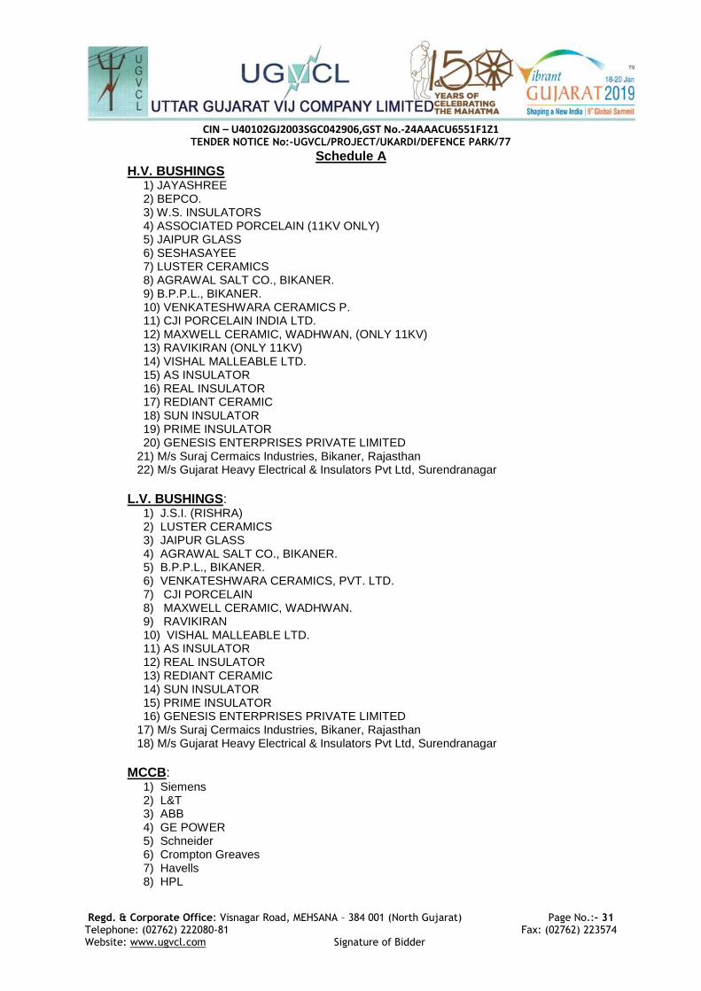
CIN – U40102GJ2003SGC042906,GST No.-24AAACU6551F1Z1
TENDER NOTICE No:-UGVCL/PROJECT/UKARDI/DEFENCE PARK/77
Regd. & Corporate Office: Visnagar Road, MEHSANA – 384 001 (North Gujarat) Page No.:- 31 Telephone: (02762) 222080-81 Fax: (02762) 223574 Website: www.ugvcl.com Signature of Bidder
Schedule A H.V. BUSHINGS
1) JAYASHREE 2) BEPCO. 3) W.S. INSULATORS 4) ASSOCIATED PORCELAIN (11KV ONLY) 5) JAIPUR GLASS 6) SESHASAYEE 7) LUSTER CERAMICS 8) AGRAWAL SALT CO., BIKANER. 9) B.P.P.L., BIKANER. 10) VENKATESHWARA CERAMICS P. 11) CJI PORCELAIN INDIA LTD. 12) MAXWELL CERAMIC, WADHWAN, (ONLY 11KV) 13) RAVIKIRAN (ONLY 11KV) 14) VISHAL MALLEABLE LTD. 15) AS INSULATOR 16) REAL INSULATOR 17) REDIANT CERAMIC 18) SUN INSULATOR 19) PRIME INSULATOR 20) GENESIS ENTERPRISES PRIVATE LIMITED
21) M/s Suraj Cermaics Industries, Bikaner, Rajasthan 22) M/s Gujarat Heavy Electrical & Insulators Pvt Ltd, Surendranagar
L.V. BUSHINGS:
1) J.S.I. (RISHRA) 2) LUSTER CERAMICS 3) JAIPUR GLASS 4) AGRAWAL SALT CO., BIKANER. 5) B.P.P.L., BIKANER. 6) VENKATESHWARA CERAMICS, PVT. LTD. 7) CJI PORCELAIN 8) MAXWELL CERAMIC, WADHWAN. 9) RAVIKIRAN 10) VISHAL MALLEABLE LTD. 11) AS INSULATOR 12) REAL INSULATOR 13) REDIANT CERAMIC 14) SUN INSULATOR 15) PRIME INSULATOR 16) GENESIS ENTERPRISES PRIVATE LIMITED
17) M/s Suraj Cermaics Industries, Bikaner, Rajasthan 18) M/s Gujarat Heavy Electrical & Insulators Pvt Ltd, Surendranagar
MCCB:
1) Siemens 2) L&T 3) ABB 4) GE POWER 5) Schneider 6) Crompton Greaves 7) Havells 8) HPL

CIN – U40102GJ2003SGC042906,GST No.-24AAACU6551F1Z1
TENDER NOTICE No:-UGVCL/PROJECT/UKARDI/DEFENCE PARK/77
Regd. & Corporate Office: Visnagar Road, MEHSANA – 384 001 (North Gujarat) Page No.:- 32 Telephone: (02762) 222080-81 Fax: (02762) 223574 Website: www.ugvcl.com Signature of Bidder
Annexure I GUARANTEED TECHNICAL PARTICULARS
Sr. No.
Particulars Unit / Type As per Firm's Offer
1 Name of manufacturer
2 Place of Manufacturing
3 Transformer capacity KVA
4 Voltage 11/0.433-0.250 KV
5 No. of Phases 3 No./1 No.
6 Vector Group DY-11
7 Type of Cooling ONAN
8 Type of Transformer Sealed/Unsealed
9 For 200 KVA/500 KVA transformers
a) No. of tap positions in HV winding
b) Voltage variation
10 Energy Efficiency Level Level-1/Level-2
11 Losses
i Core loss Watts
a) at Normal Voltage Watts
b) at Maximum Voltage Watts
ii Full Load losses at 75 deg.C. Watts
iii Total losses at 50 % loading at 75 deg.C. Watts
iv Total losses at 100 % loading at 75 deg.C. Watts
12 Percentage Impedance at 75 deg.C. %
13 Maximum temperature rise of
a) Windings by resistance method 40 deg C (35 deg C for 5KVA)
b) Oil by Thermometer 35 deg C (30 deg C for 5KVA)
14 Clearances
a) Core & LV mm
b) LV & HV mm
c) HV Phase to Phase mm

CIN – U40102GJ2003SGC042906,GST No.-24AAACU6551F1Z1
TENDER NOTICE No:-UGVCL/PROJECT/UKARDI/DEFENCE PARK/77
Regd. & Corporate Office: Visnagar Road, MEHSANA – 384 001 (North Gujarat) Page No.:- 33 Telephone: (02762) 222080-81 Fax: (02762) 223574 Website: www.ugvcl.com Signature of Bidder
Sr. No.
Particulars Unit / Type As per Firm's Offer
d) End insulation clearance to Earth mm
e) Any point of winding to tank mm
f) HV to earth creepage distance mm
g) LV to earth creepage distance mm
15 Efficiency at 75 deg.C.
a) Unity P.F.
1) 125% load %
2) 100% load %
3) 75% load %
4) 50% load %
5) 25% load %
b) 0.8 P.F.
1) 125% load %
2) 100% load %
3) 75% load %
4) 50% load %
5) 25% load %
16 Regulation at
a) Unity P.F.
b) 0.8 P.F. at 75 deg.C.
17 CORE CRGO/ Amorphous
i Core Grade
ii Core diameter mm
iii Gross Core area Mtr²
iv Net Core area Mtr²
v Flux density Wb/Mtr²
vii Wt. of Core Kg
viii Loss per kg. of Core at the specified Flux density
Watts
ix Core window height mm
x Centre to centre distance of the core mm
xi The nominal flux density at

CIN – U40102GJ2003SGC042906,GST No.-24AAACU6551F1Z1
TENDER NOTICE No:-UGVCL/PROJECT/UKARDI/DEFENCE PARK/77
Regd. & Corporate Office: Visnagar Road, MEHSANA – 384 001 (North Gujarat) Page No.:- 34 Telephone: (02762) 222080-81 Fax: (02762) 223574 Website: www.ugvcl.com Signature of Bidder
Sr. No.
Particulars Unit / Type As per Firm's Offer
a) 100% rated voltage ≤ 1.69 Wb/Mtr²
b) 110% of rated voltage ≤1.9 Wb/Mtr²
xii % No load current of full load current at rated voltage and frequency on the secondary and Increase of voltage by 112.5%
(i) CRGO Core: at 100% and 112.5% of rated Voltage
a) Up to 200 KVA Transformer ≤ 3% and ≤ 6 %
b) Above 200 KVA Transformer ≤ 2% and ≤ 5 %
(ii) Amorphous Core: at 100% and 112.5% of rated Voltage
a) All Ratings ≤ 2% and ≤ 5 %
18 WINDINGS Aluminium / Copper
i No. of L.V. Turns No.
ii No. of H V turns No.
iii Size of LV Conductor bare/ covered mm
iv Size of HV conductor bare/covered mm
v No. of parallels No.
vii Resistance of HV winding at 20 deg.C Ohm
viii Resistance of LV winding at 20 deg.C Ohm
ix Current density of LV winding Amps/sq.mm.
x Current density of HV winding Amps/sq.mm.
xi Wt. of the LV winding for Transformer kg.
xii Wt. of the HV winding for Transformer kg.
xiii No. of LV Coils/phase No.
xiv No. of HV coils / phase No.
xv Height of LV Windings mm
xvi Height of HV winding mm
xvii ID/OD of LV winding mm
xviii ID/OD of HV winding mm
xix Size of the duct in LV winding mm
xx Size of the duct in HV winding mm

CIN – U40102GJ2003SGC042906,GST No.-24AAACU6551F1Z1
TENDER NOTICE No:-UGVCL/PROJECT/UKARDI/DEFENCE PARK/77
Regd. & Corporate Office: Visnagar Road, MEHSANA – 384 001 (North Gujarat) Page No.:- 35 Telephone: (02762) 222080-81 Fax: (02762) 223574 Website: www.ugvcl.com Signature of Bidder
Sr. No.
Particulars Unit / Type As per Firm's Offer
xxi Size of the duct between HV & LV mm
xxii Inter layer insulation provided in design for
1) Top & bottom layer
2) In between all layer
3) Details of end insulation
4) Whether wedges are provided at 50% turns of the HV coil
xxiii Insulation materials provided
a) For Conductors
(1) HV
(2) LV
B) For Core
xxiv Material and Size of the wire used
1) HV a) SWG No.
b) Dia mm
2) LV a) Strip size mm X mm
b) No. of Conductors in parallel No
c) Total area of cross section sq.mm.
19 Weight content of
a) Core lamination (min) KG
b) Windings (min) Aluminium/Copper KG
c) Tank & Fittings KG
d) Oil KG
e) Oil qty (min) Litre
f) Total Weight KG
20 Oil Data
1. Qty for first filling (min) Litre
2. Grade of oil used
3. Maker’s name
4. BDV at the time of filling KV
21 Transformer
1) Overall length x breadth x height mm X mm X mm

CIN – U40102GJ2003SGC042906,GST No.-24AAACU6551F1Z1
TENDER NOTICE No:-UGVCL/PROJECT/UKARDI/DEFENCE PARK/77
Regd. & Corporate Office: Visnagar Road, MEHSANA – 384 001 (North Gujarat) Page No.:- 36 Telephone: (02762) 222080-81 Fax: (02762) 223574 Website: www.ugvcl.com Signature of Bidder
Sr. No.
Particulars Unit / Type As per Firm's Offer
2) Shape of Tank
2) Tank length x breadth x height mm X mm X mm
3) Thickness of plates for
a) Side plate (min) mm
b) Top & Bottom plate (min) mm
4) Conservator Dimensions mm X mm
5) Tank base channel dimensions mm X mm X mm
22 HV Bushings & Terminals
1) Make of HV bushing
2) Rating in KV KV
3) Turret Height mm
4) Material of HV terminal Brass/Copper
5) Current Density of HV terminal Amps/sq.mm.
23 LV Bushings & Terminals
1) Make of LV bushing
2) Rating in KV KV
3) Turret Height mm
4) Material of LV terminal Brass/Copper
5) Current Density of LV terminal Amps/sq.mm.
24 Details of MCCB (for transformers having rating upto 25 KVA)
Make
Rated thermal current Amp.
Current setting Amp.
Minimum short circuit breaking current KA
25 Radiation
1) Heat dissipation by tank walls exclusive top & bottom
2) Heat dissipation by cooling tube
3) Dia & thickness of cooling tube

CIN – U40102GJ2003SGC042906,GST No.-24AAACU6551F1Z1
TENDER NOTICE No:-UGVCL/PROJECT/UKARDI/DEFENCE PARK/77
Regd. & Corporate Office: Visnagar Road, MEHSANA – 384 001 (North Gujarat) Page No.:- 37 Telephone: (02762) 222080-81 Fax: (02762) 223574 Website: www.ugvcl.com Signature of Bidder
Sr. No.
Particulars Unit / Type As per Firm's Offer
4) Whether calculation sheet for selecting cooling area to ensure that the transformer is capable of giving continuous rated output without exceeding temperature rise is enclosed.
Yes/No
26 Whether the name plate gives all particulars as required in Tender
Yes/No
27 Whether the transformer offered is already type tested for the design and test reports enclosed
Yes/No

CIN – U40102GJ2003SGC042906,GST No.-24AAACU6551F1Z1
TENDER NOTICE No:-UGVCL/PROJECT/UKARDI/DEFENCE PARK/77
Regd. & Corporate Office: Visnagar Road, MEHSANA – 384 001 (North Gujarat) Page No.:- 38 Telephone: (02762) 222080-81 Fax: (02762) 223574 Website: www.ugvcl.com Signature of Bidder
Annexure II
Digit/letter No.
Details TIN Remark
1 Name of Company
M First letter of DISCOM name
2 KVA rating 5 for 5/10/16/25/63/100/200/500 KVA ratings digits will be respectively 1/2/3/4/5/6/7/8
3 Type of Core
Material 1 CRGO-1,Amorphous-2
4 Core construction
1 Stack-1, Wound-2
5 Supplier Name
Code
1 each supplier will be given 2 digit code no. e.g. M/s XYZ given code no.15 6 5
7 Month of
manufacturing
0 2 digits for Month of manufacturing
8 2
9 Year of
manufacturing
1 2 digits for Year of manufacturing
10 7
11
CPP Tender No.
9
4 digits for CPP tender no.
12 0
13 3
14 2
15 Sr. No. of
transformer given by Supplier
0 5 digits for transformer sr. no. given by supplier (e.g. M/s XYZ will give transformer sr. no. from 00001 to 00260 for P.O. of 260 no. transformers issued to them vide CPP tender no.9032 )
16 0
17 0
18 0
19 1
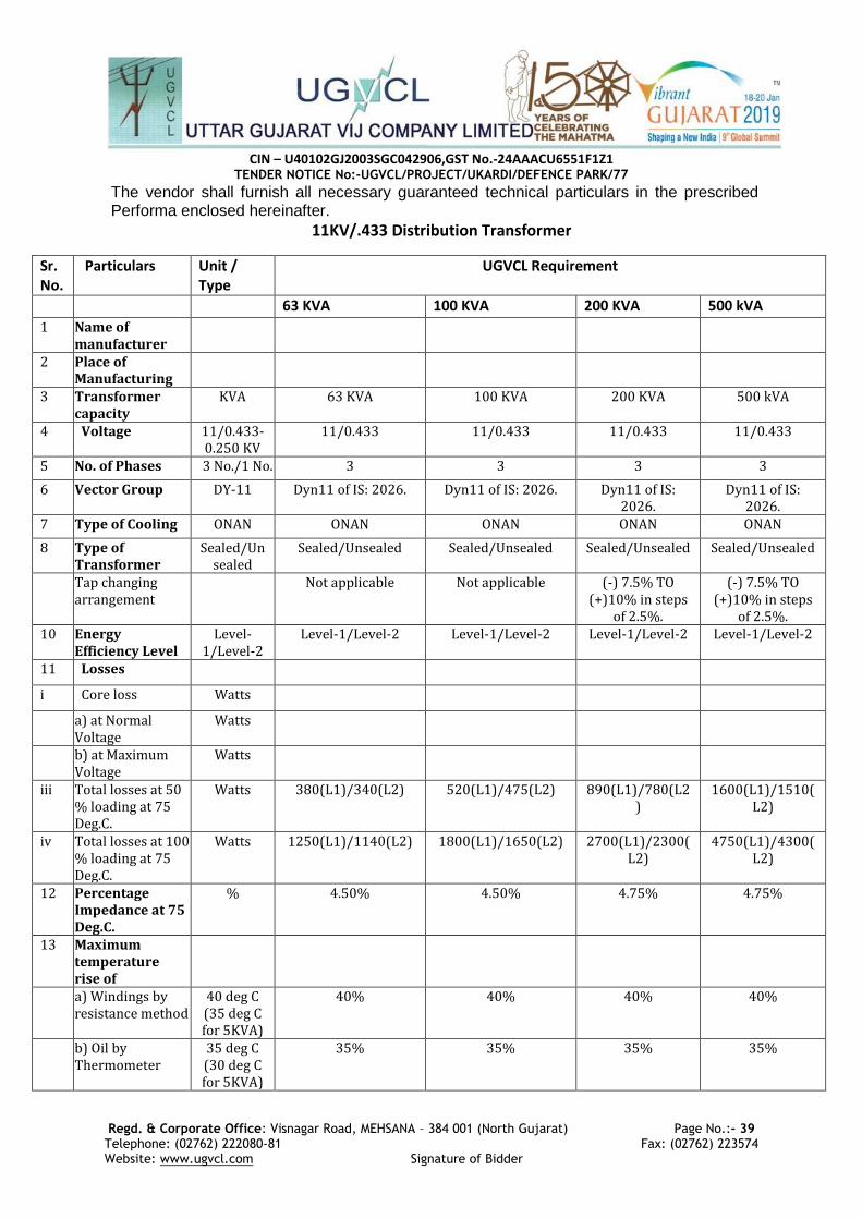
CIN – U40102GJ2003SGC042906,GST No.-24AAACU6551F1Z1
TENDER NOTICE No:-UGVCL/PROJECT/UKARDI/DEFENCE PARK/77
Regd. & Corporate Office: Visnagar Road, MEHSANA – 384 001 (North Gujarat) Page No.:- 39 Telephone: (02762) 222080-81 Fax: (02762) 223574 Website: www.ugvcl.com Signature of Bidder
The vendor shall furnish all necessary guaranteed technical particulars in the prescribed Performa enclosed hereinafter.
11KV/.433 Distribution Transformer
Sr. No.
Particulars Unit / Type
UGVCL Requirement
63 KVA 100 KVA 200 KVA 500 kVA
1 Name of manufacturer
2 Place of Manufacturing
3 Transformer capacity
KVA 63 KVA 100 KVA 200 KVA 500 kVA
4 Voltage 11/0.433-0.250 KV
11/0.433 11/0.433 11/0.433 11/0.433
5 No. of Phases 3 No./1 No. 3 3 3 3
6 Vector Group DY-11 Dyn11 of IS: 2026. Dyn11 of IS: 2026. Dyn11 of IS: 2026.
Dyn11 of IS: 2026.
7 Type of Cooling ONAN ONAN ONAN ONAN ONAN
8 Type of Transformer
Sealed/Unsealed
Sealed/Unsealed Sealed/Unsealed Sealed/Unsealed Sealed/Unsealed
Tap changing arrangement
Not applicable Not applicable (-) 7.5% TO (+)10% in steps
of 2.5%.
(-) 7.5% TO (+)10% in steps
of 2.5%. 10 Energy
Efficiency Level Level-
1/Level-2 Level-1/Level-2 Level-1/Level-2 Level-1/Level-2 Level-1/Level-2
11 Losses
i Core loss Watts
a) at Normal Voltage
Watts
b) at Maximum Voltage
Watts
iii Total losses at 50 % loading at 75 Deg.C.
Watts 380(L1)/340(L2) 520(L1)/475(L2) 890(L1)/780(L2)
1600(L1)/1510(L2)
iv Total losses at 100 % loading at 75 Deg.C.
Watts 1250(L1)/1140(L2) 1800(L1)/1650(L2) 2700(L1)/2300(L2)
4750(L1)/4300(L2)
12 Percentage Impedance at 75 Deg.C.
% 4.50% 4.50% 4.75% 4.75%
13 Maximum temperature rise of
a) Windings by resistance method
40 deg C (35 deg C for 5KVA)
40% 40% 40% 40%
b) Oil by Thermometer
35 deg C (30 deg C for 5KVA)
35% 35% 35% 35%
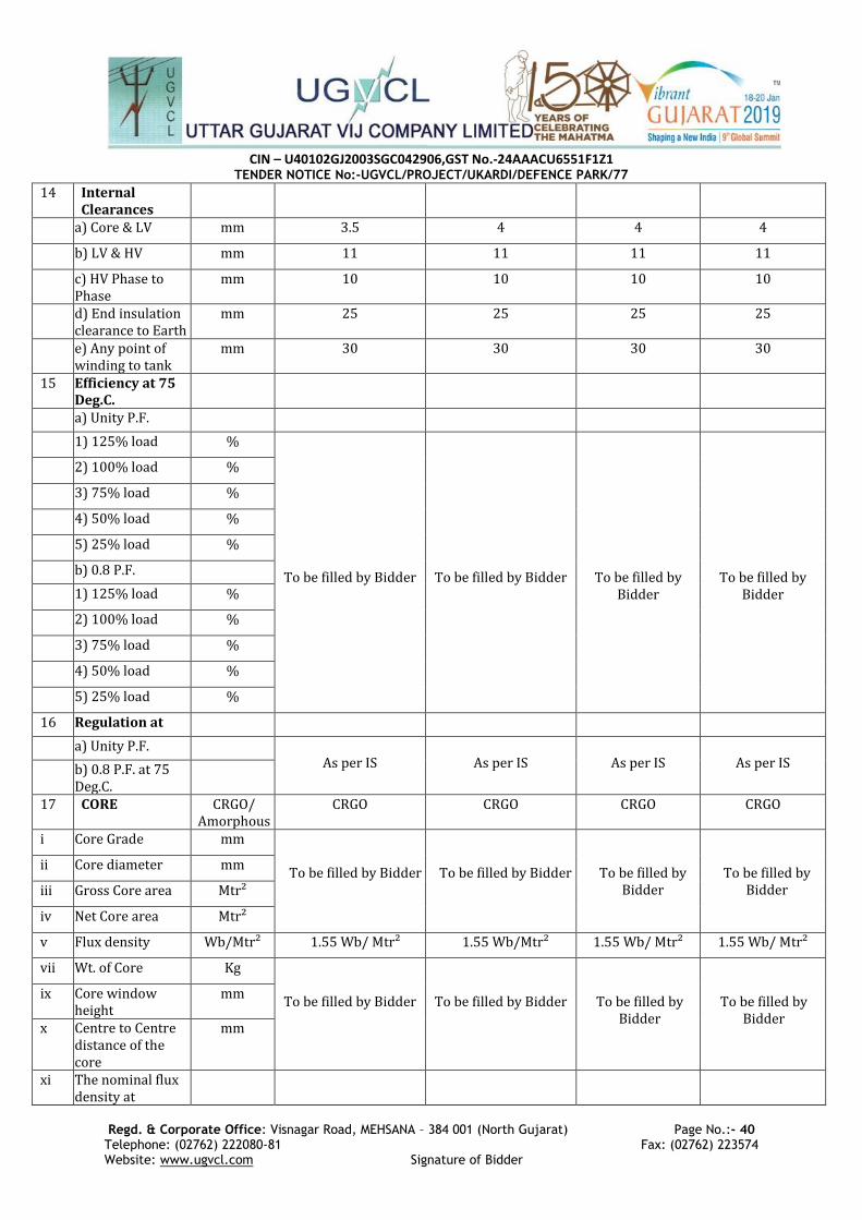
CIN – U40102GJ2003SGC042906,GST No.-24AAACU6551F1Z1
TENDER NOTICE No:-UGVCL/PROJECT/UKARDI/DEFENCE PARK/77
Regd. & Corporate Office: Visnagar Road, MEHSANA – 384 001 (North Gujarat) Page No.:- 40 Telephone: (02762) 222080-81 Fax: (02762) 223574 Website: www.ugvcl.com Signature of Bidder
14 Internal Clearances
a) Core & LV mm 3.5 4 4 4
b) LV & HV mm 11 11 11 11
c) HV Phase to Phase
mm 10 10 10 10
d) End insulation clearance to Earth
mm 25 25 25 25
e) Any point of winding to tank
mm 30 30 30 30
15 Efficiency at 75 Deg.C.
a) Unity P.F.
1) 125% load %
To be filled by Bidder
To be filled by Bidder
To be filled by Bidder
To be filled by Bidder
2) 100% load %
3) 75% load %
4) 50% load %
5) 25% load %
b) 0.8 P.F.
1) 125% load %
2) 100% load %
3) 75% load %
4) 50% load %
5) 25% load %
16 Regulation at
a) Unity P.F. As per IS
As per IS
As per IS
As per IS b) 0.8 P.F. at 75
Deg.C.
17 CORE CRGO/ Amorphous
CRGO CRGO CRGO CRGO
i Core Grade mm
To be filled by Bidder
To be filled by Bidder
To be filled by Bidder
To be filled by Bidder
ii Core diameter mm
iii Gross Core area Mtr²
iv Net Core area Mtr²
v Flux density Wb/Mtr² 1.55 Wb/ Mtr² 1.55 Wb/Mtr² 1.55 Wb/ Mtr² 1.55 Wb/ Mtr²
vii Wt. of Core Kg
To be filled by Bidder
To be filled by Bidder
To be filled by Bidder
To be filled by Bidder
ix Core window height
mm
x Centre to Centre distance of the core
mm
xi The nominal flux density at

CIN – U40102GJ2003SGC042906,GST No.-24AAACU6551F1Z1
TENDER NOTICE No:-UGVCL/PROJECT/UKARDI/DEFENCE PARK/77
Regd. & Corporate Office: Visnagar Road, MEHSANA – 384 001 (North Gujarat) Page No.:- 41 Telephone: (02762) 222080-81 Fax: (02762) 223574 Website: www.ugvcl.com Signature of Bidder
a) 100% rated voltage
≤ 1.69 Wb/Mtr²
≤ 1.69 Wb/Mtr² ≤ 1.69 Wb/Mtr² ≤ 1.69 Wb/Mtr² ≤ 1.69 Wb/Mtr²
b) 110% of rated voltage
≤1.9 Wb/Mtr²
≤1.9 Wb/Mtr² ≤1.9 Wb/Mtr² ≤1.9 Wb/Mtr² ≤1.9 Wb/Mtr²
xii (i) CRGO Core: at 100% and 112.5% of rated Voltage
≤ 3% and ≤ 6 %
≤ 3% and ≤ 6 % ≤ 3% and ≤ 6 % ≤ 3% and ≤ 6 % ≤ 3% and ≤ 6 %
a) Up to 200 KVA Transformer
≤ 3% and ≤ 6 %
≤ 3% and ≤ 6 % ≤ 3% and ≤ 6 % ≤ 3% and ≤ 6 % ≤ 3% and ≤ 6 %
b) Above 200 KVA Transformer
≤ 2% and ≤ 5 %
≤ 2% and ≤ 5 % ≤ 2% and ≤ 5 % ≤ 2% and ≤ 5 % ≤ 2% and ≤ 5 %
(ii) Amorphous Core: at 100% and 112.5% of rated Voltage.
a) All Ratings ≤ 2% and ≤ 5 %
≤ 2% and ≤ 5 % ≤ 2% and ≤ 5 % ≤ 2% and ≤ 5 % ≤ 2% and ≤ 5 %
18 WINDINGS Aluminium /
Copper
To be filled by Bidder To be filled by Bidder To be filled by Bidder
To be filled by Bidder
i No. of L.V. Turns No.
To be filled by Bidder
To be filled by Bidder
To be filled by Bidder
To be filled by Bidder
ii No. of H V turns No.
iii Size of LV Conductor bare/ covered
mm
iv Size of HV conductor bare/covered
mm
v No. of parallels No.
vii Resistance of HV winding at 20 Deg.C
Ohm
viii Resistance of LV winding at 20 Deg.C
Ohm
ix Current density of LV winding
Amps/sq.mm.
1 Amp/sq.mm and 2Amp/sq.mm(Alu./C
opper Cond.)
1 Amp/sq.mm and 2Amp/sq.mm(Alu./C
opper Cond.)
1 Amp/sq.mm and
2Amp/sq.mm(Alu./Copper Cond.)
1 Amp/sq.mm and
2Amp/sq.mm(Alu./Copper Cond.)
x Current density of HV winding
Amps/sq.mm.
1 Amp/sq.mm and 2Amp/sq.mm(Alu./C
opper Cond.)
1 Amp/sq.mm and 2Amp/sq.mm(Alu./C
opper Cond.)
1 Amp/sq.mm and
2Amp/sq.mm(Alu./Copper Cond.)
1 Amp/sq.mm and
2Amp/sq.mm(Alu./Copper Cond.)
xi Wt. of the LV winding for Transformer
kg.
To be filled by Bidder
To be filled by Bidder
To be filled by Bidder
To be filled by Bidder
xii Wt. of the HV
winding for Transformer
kg.
xiii No. of LV Coils/phase
No. 1 1 1 1

CIN – U40102GJ2003SGC042906,GST No.-24AAACU6551F1Z1
TENDER NOTICE No:-UGVCL/PROJECT/UKARDI/DEFENCE PARK/77
Regd. & Corporate Office: Visnagar Road, MEHSANA – 384 001 (North Gujarat) Page No.:- 42 Telephone: (02762) 222080-81 Fax: (02762) 223574 Website: www.ugvcl.com Signature of Bidder
xiv No. of HV coils / phase
No. 4 4 4 4
xiv Size of the duct in LV winding
mm 3 mm 3 mm 3 mm 3 mm
xiv Size of the duct in HV winding
mm 3 mm 3 mm 3 mm 3 mm
xiv Size of the duct between HV & LV
mm
xiv Inter layer insulation provided in design for
1) Top and Bottom yoke insulation
Perma wood or Haldi wood blocks
Perma wood or Haldi wood blocks
Perma wood or Haldi wood
blocks
Perma wood or Haldi wood
blocks 2) In between all
layer
3) Details of end insulation
xxiii Insulation materials provided
a) For Conductors
To be filled by Bidder
To be filled by Bidder
To be filled by Bidder
To be filled by Bidder
(1) HV
(2) LV
B) For Core
19 Weight content of
a) Core lamination (min)
KG To be filled by Bidder To be filled by Bidder To be filled by Bidder
To be filled by Bidder
b) Windings (min) Aluminium/Copper
KG To be filled by Bidder To be filled by vendor To be filled by vendor
To be filled by vendor
c) Tank & Fittings KG To be filled by Bidder To be filled by Bidder To be filled by Bidder
To be filled by Bidder
d) Oil KG
e) Oil Qty (min) Litre
f) Total Weight KG
20 Oil Data
1. Qty for first filling (min)
Litre To be filled by Bidder To be filled by Bidder To be filled by Bidder
To be filled by Bidder
2. Grade of oil used As per IS:335 As per IS:335 As per IS:335 As per IS:335
3.The specific resistance of the oil
> >35X1012 ohm-cm at 27⁰C
>35X1012 ohm-cm at 27⁰C
>35X1012 ohm-cm at 27⁰C
>35X1012 ohm-cm at 27⁰C
4. Maker’s name To be filled by Bidder To be filled by Bidder To be filled by Bidder
To be filled by Bidder

CIN – U40102GJ2003SGC042906,GST No.-24AAACU6551F1Z1
TENDER NOTICE No:-UGVCL/PROJECT/UKARDI/DEFENCE PARK/77
Regd. & Corporate Office: Visnagar Road, MEHSANA – 384 001 (North Gujarat) Page No.:- 43 Telephone: (02762) 222080-81 Fax: (02762) 223574 Website: www.ugvcl.com Signature of Bidder
5. BDV at the time of filling
KV
21 Transformer
1) Overall length x breadth x height
mm X mm X mm
As per IS As per IS As per IS As per IS
2) Shape of Tank Rectangular/Elliptical/Corrugated
Rectangular/Elliptical/Corrugated
Rectangular/Elliptical/Corrugated
Rectangular/Elliptical/Corrugated
2) Tank length x breadth x height
mm X mm X mm
As per IS As per IS As per IS As per IS
3) Thickness of plates for
a) Side plate (min) mm 3.15 mm 3.15 mm 4.5mm 4.5mm
b) Top & Bottom plate (min)
mm 5 mm 5 mm 6mm 6mm
4) Conservator Dimensions
mm X mm
5) Tank base channel dimensions
mm X mm X mm
75 x 40 x 460 mm 76 x 40 x 460 mm 100 x 50 mm 100 x 50 mm
22 HV Bushings & Terminals
1) Make of HV bushing
Mentioned in Schedule A of TS
Mentioned in Schedule A of TS
Mentioned in Schedule A of TS
Mentioned in Schedule A of TS
2) Rating in KV KV 17.5 KV 17.5 KV 17.5 KV 17.5 KV
3) Turret Height mm Minimum 25 to 30mm
Minimum 25 to 30mm
Minimum 25 to 30mm
Minimum 25 to 30mm
4) Material of HV terminal
Brass/Copper
Brass/Copper Brass/Copper Brass/Copper Brass/Copper
5) Current Density of HV terminal
Amps/sq.mm.
1 Amp per sq.mm for Brass / 2 Amp per sq.mm for copper
terminals.
1 Amp per sq.mm for Brass / 2 Amp per sq.mm for copper
terminals.
1 Amp per sq.mm for Brass
/ 2 Amp per sq.mm for
copper terminals.
1 Amp per sq.mm for Brass / 2 Amp
per sq.mm for copper terminals.
23 LV Bushings & Terminals
1) Make of LV bushing
As Per IS-3347 As Per IS-3347 As Per IS-3347 As Per IS-3347
2) Rating in KV KV 1.1 KV 1.1 KV 1.1 KV 1.1 KV
3) Turret Height mm minimum 10mm minimum 10mm minimum 10mm minimum 10mm
4) Material of LV terminal
Brass/Copper
Brass/Copper Brass/Copper Brass/Copper Brass/Copper
5) Current Density of LV terminal
Amps/sq.mm.
1 Amp per sq.mm for Brass / 2 Amp per sq.mm for copper
terminals.
1 Amp per sq.mm for Brass / 2 Amp per sq.mm for copper
terminals.
1 Amp per sq.mm for Brass
/ 2 Amp per sq.mm for
copper terminals.
1 Amp per sq.mm for Brass / 2 Amp
per sq.mm for copper terminals.

CIN – U40102GJ2003SGC042906,GST No.-24AAACU6551F1Z1
TENDER NOTICE No:-UGVCL/PROJECT/UKARDI/DEFENCE PARK/77
Regd. & Corporate Office: Visnagar Road, MEHSANA – 384 001 (North Gujarat) Page No.:- 44 Telephone: (02762) 222080-81 Fax: (02762) 223574 Website: www.ugvcl.com Signature of Bidder
25 Radiation
1) Heat dissipation by tank walls exclusive top & bottom
2) Heat dissipation by cooling tube
3) Dia & thickness of cooling tube
Yes/No
26 Whether the name plate gives all particulars as required in Tender.
Yes/No
27 Whether the transformer offered is already type tested for the design and test reports enclosed.
Yes/No