Embed Size (px)
Citation preview
0093-9994 (c) 2013 IEEE. Personal use is permitted, but republication/redistribution requires IEEE permission. Seehttp://www.ieee.org/publications_standards/publications/rights/index.html for more information.
This article has been accepted for publication in a future issue of this journal, but has not been fully edited. Content may change prior to final publication. Citation information: DOI10.1109/TIA.2014.2309175, IEEE Transactions on Industry Applications
Abstract -- The industrial distribution power systems in Northern Alberta supplies electrical energy to satellite locations and mining areas. In some aspects, these systems differ from their counterparts in regular utility distribution cases. Accordingly, they require special attention when performing transient recovery voltage (TRV) studies and identifying ratings for new breakers to be added to the system. Meanwhile, North American (IEEE) and European (IEC) Standards are embarking on significant efforts to harmonize breaker specifications and testing requirements including TRV tests. An Electro Magnetic Transient Program (EMTP) study has been performed to verify system TRV requirements under different conditions against Standard requirements and supplier’s provided test data. Concerns, lessons learned and some other findings associated with the study are documented in the paper for future references and for advancing robust usage of EMTP (ATP) for the performance of such studies for sub-transmission and distribution systems in different electrical systems.
Index Terms- Transient Recovery Voltage, TRV, HV Circuit Breakers, MV Circuit Breaker, Breaker Ratings, EMTP
I. INTRODUCTION
The de-regulation of electrical generation in Alberta
allowed large industrial system identities to own and/or operate their electrical generation, transmission and distribution equipment, lines and systems within and in-between their facilities. Upon getting the required permits and after being granted the status of Industrial System Designate (ISD), industrial facilities could generate, transmit and distribute their electrical energy within the designated area. As long as they adhered to the applicable requirements, real time connections to the Alberta Integrated System (AIES) are permitted at specific points of common coupling where they may export excess energy or import shortfall energy as the case may be. Other transmission or distribution facilities and systems are owned and operated by an area designated utility as listed in the Electric Utility Act, the Alberta Utilities Commission (AUC) and the Alberta Electric System Operator (AESO).
When initially developed, the subject area was remote
with a sparse population, little generating capacity and scarce voltage support. Since then, the oil recovery in Fort MacMurray considerably changed every aspect of the area’s electrical system. Now there are several generation and
cogeneration facilities, a number of interconnecting lines and far more complex system configurations. The system voltages in that area run with +5% to +10% voltage above their mid class point. The area’s 69 kV system is running at 72kV to 74 kV continuous operating voltage with some areas having a maximum continuous operating voltage as high as 75.9 kV.
Another aspect of the subject systems is associated with
how the system neutral is connected to ground. 69kV systems in most North American utilities have solidly grounded neutral systems. In the subject case, the main source transformers are equipped with 200A Neutral Resistance Grounding (NRG) arrangements to suit mining applications for the area. The Mining Codes and Standards require that Ground Potential Rise be limited to 100V. Such limitations would have been difficult with solidly neutral grounded systems, due to high line to ground fault currents. The case in this paper is selected to highlight factors associated with TRV studies in industrial and mining areas where system voltages, neutral connections and overall operating conditions may differ from typical distribution utility cases.
It is assumed that the facility substation is an existing
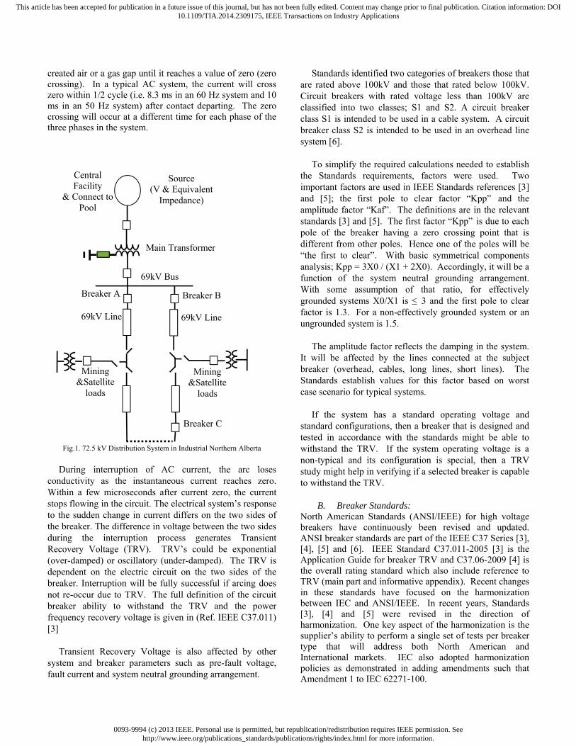
substation that, over two decades, encountered several changes. A new breaker was to be added to the existing substation in order to provide a looped circuit supplying satellite and mining areas. Inherited operating practices require the system to operate with a minimum bus voltage of 72.5 kV with a potential to increase maximum continuous operating voltage unless restricted by identified system needs. The breaker shall be specified to North American Standards which have been recently updated to harmonize with IEC Standards. Fig. 1 shows an overall single line diagram for the case study.
II. BREAKER TRANSIENT RECOVERY VOLTAGES
A. What is Transient Recovery Voltage?
When a breaker trips, its 3-phase poles mechanically travel apart introducing gaps between their stationary and moving parts. In simple arrangements each side of the pole could be a supply side and or a load side of the breaker. The current continues to flow in ionized, newly
Circuit Breaker Transient Recovery Voltage Requirements for
Medium Voltage Systems with NRG Rasheek Rifaat, P.Eng., IEEESM Tarjit Singh Lally, P.Eng. James Hong, EIT [email protected] [email protected] [email protected] Jacobs, Calgary, AB, Canada Jacobs, Calgary, AB, Canada Jacobs, Calgary, AB, Canada
0093-9994 (c) 2013 IEEE. Personal use is permitted, but republication/redistribution requires IEEE permission. Seehttp://www.ieee.org/publications_standards/publications/rights/index.html for more information.
This article has been accepted for publication in a future issue of this journal, but has not been fully edited. Content may change prior to final publication. Citation information: DOI10.1109/TIA.2014.2309175, IEEE Transactions on Industry Applications
created air or a gas gap until it reaches a value of zero (zero crossing). In a typical AC system, the current will cross zero within 1/2 cycle (i.e. 8.3 ms in an 60 Hz system and 10 ms in an 50 Hz system) after contact departing. The zero crossing will occur at a different time for each phase of the three phases in the system.
Fig.1. 72.5 kV Distribution System in Industrial Northern Alberta
During interruption of AC current, the arc loses
conductivity as the instantaneous current reaches zero. Within a few microseconds after current zero, the current stops flowing in the circuit. The electrical system’s response to the sudden change in current differs on the two sides of the breaker. The difference in voltage between the two sides during the interruption process generates Transient Recovery Voltage (TRV). TRV’s could be exponential (over-damped) or oscillatory (under-damped). The TRV is dependent on the electric circuit on the two sides of the breaker. Interruption will be fully successful if arcing does not re-occur due to TRV. The full definition of the circuit breaker ability to withstand the TRV and the power frequency recovery voltage is given in (Ref. IEEE C37.011) [3]
Transient Recovery Voltage is also affected by other
system and breaker parameters such as pre-fault voltage, fault current and system neutral grounding arrangement.
Standards identified two categories of breakers those that are rated above 100kV and those that rated below 100kV. Circuit breakers with rated voltage less than 100kV are classified into two classes; S1 and S2. A circuit breaker class S1 is intended to be used in a cable system. A circuit breaker class S2 is intended to be used in an overhead line system [6].
To simplify the required calculations needed to establish
the Standards requirements, factors were used. Two important factors are used in IEEE Standards references [3] and [5]; the first pole to clear factor “Kpp” and the amplitude factor “Kaf”. The definitions are in the relevant standards [3] and [5]. The first factor “Kpp” is due to each pole of the breaker having a zero crossing point that is different from other poles. Hence one of the poles will be “the first to clear”. With basic symmetrical components analysis; Kpp = 3X0 / (X1 + 2X0). Accordingly, it will be a function of the system neutral grounding arrangement. With some assumption of that ratio, for effectively grounded systems X0/X1 is ≤ 3 and the first pole to clear factor is 1.3. For a non-effectively grounded system or an ungrounded system is 1.5.
The amplitude factor reflects the damping in the system.
It will be affected by the lines connected at the subject breaker (overhead, cables, long lines, short lines). The Standards establish values for this factor based on worst case scenario for typical systems.
If the system has a standard operating voltage and
standard configurations, then a breaker that is designed and tested in accordance with the standards might be able to withstand the TRV. If the system operating voltage is a non-typical and its configuration is special, then a TRV study might help in verifying if a selected breaker is capable to withstand the TRV.
B. Breaker Standards:
North American Standards (ANSI/IEEE) for high voltage breakers have continuously been revised and updated. ANSI breaker standards are part of the IEEE C37 Series [3], [4], [5] and [6]. IEEE Standard C37.011-2005 [3] is the Application Guide for breaker TRV and C37.06-2009 [4] is the overall rating standard which also include reference to TRV (main part and informative appendix). Recent changes in these standards have focused on the harmonization between IEC and ANSI/IEEE. In recent years, Standards [3], [4] and [5] were revised in the direction of harmonization. One key aspect of the harmonization is the supplier’s ability to perform a single set of tests per breaker type that will address both North American and International markets. IEC also adopted harmonization policies as demonstrated in adding amendments such that Amendment 1 to IEC 62271-100.
Central Facility
& Connect to Pool
Main Transformer
Mining &Satellite
loads
Breaker A
Breaker C
Breaker B
Source (V & Equivalent
Impedance)
69kV Bus
Mining &Satellite
loads
69kV Line 69kV Line
0093-9994 (c) 2013 IEEE. Personal use is permitted, but republication/redistribution requires IEEE permission. Seehttp://www.ieee.org/publications_standards/publications/rights/index.html for more information.
This article has been accepted for publication in a future issue of this journal, but has not been fully edited. Content may change prior to final publication. Citation information: DOI10.1109/TIA.2014.2309175, IEEE Transactions on Industry Applications
C. Applications of Standards to Case Study:
From Standard IEEE- C37.06 [4] Table 6:
- Breaker Class is S2 , circuit breaker is rated below 100kV for Overhead Lines
- System is non-effectively grounded,
- Breaker Rated Maximum Voltage 72.5kV
The rated maximum operating voltage for breakers was also defined in [5]. The definition stipulates that such rating is “the upper limit for operation”. Hence, for a typical 69 kV system with 5% margin, 72.5kV is the proper rated maximum voltage. As explained in earlier sections of the paper, the 69kV system in Northern Alberta is labeled as a 72.5 kV System. For this system, the rated maximum voltage is 72.5kV +5% (76 kV) which is a non-standard maximum voltage for breakers under the updated Standards. Never-the-less, selecting a suitable breaker for the subject system would be another part of the breaker selection exercise. The verifications for the TRV part might be done utilizing the updated Standards, supplier’s data sheet, breaker type tests and the EMTP Model of the subject system.
Breaker suppliers have been offering international breakers with higher voltage classes (i.e. 100 kV, 115 kV, etc.) and re-adjusting them for the area’s specifications. Most of such voltages are not typical in North America. Hence the supplier’s approach would be to re-adapt the original breaker type tests as much as possible and supplement them if necessary by IEEE tests. Such readjustment will mean that TRV type tests could differ from breakers made entirely to North American Standards. In the case study, information was requested from the suppliers and test results were received and used in the TRV Study
D. Breaker TRV and Test Requirements The Standards show what TRV parameters are to be
expected from the supplier for each breaker class. Table 7 in reference [6] shows the ratings for TRV in breakers less than 100kV rating and Class S2. It might be observed that the Standard values are preferred values and not mandatory. It might also be observed that TRV parameters are shown at different values of circuit breaker short circuit data namely: T100 (100%), T60 (60%), T30 (30%) and T10 (10%). For 72.5 kV Breakers Table 1 of this paper shows summary of TRV peak voltage values as extracted from Table 7 of the Standards to demonstrate how calculations are conducted on selected breaker ratings and for reference purposes. As an example, If the system‘s ultimate short circuit current is between 24kA and 40kA, then the breaker T100 values shall be used. If the system’s ultimate short circuit current is between 12kA and 24kA then T60 values of 146kA can be used. Similar derivations could be used for T30 and T10
conditions.
TABLE I: T-VALUE VERSUS TRV PEAK FOR 72.5 KV BREAKERS
SC Current in kA Amplitude Factor TRV Peak
Value kV
T100 40 1.54 137
T60 24 1.65 146
T30 12 1.74 155
T10 4 1.80 160
III. TRV STUDY USING EMTP The calculations to obtain the peak value at T10 for 72
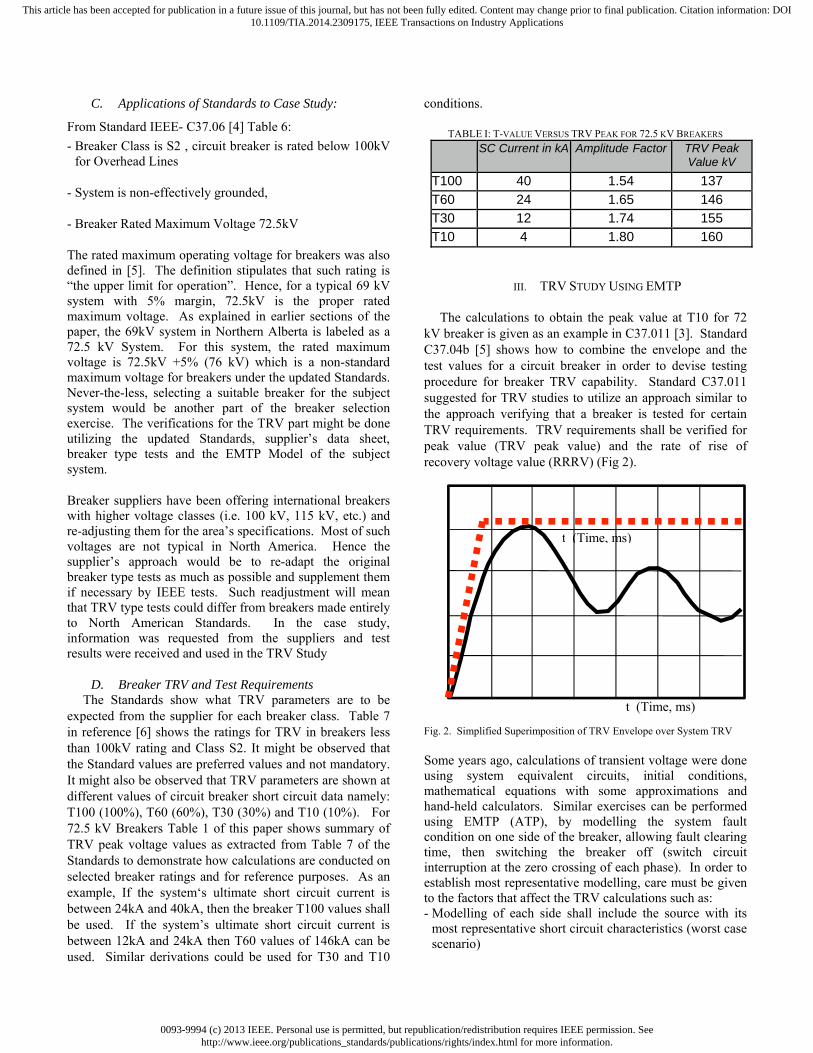
kV breaker is given as an example in C37.011 [3]. Standard C37.04b [5] shows how to combine the envelope and the test values for a circuit breaker in order to devise testing procedure for breaker TRV capability. Standard C37.011 suggested for TRV studies to utilize an approach similar to the approach verifying that a breaker is tested for certain TRV requirements. TRV requirements shall be verified for peak value (TRV peak value) and the rate of rise of recovery voltage value (RRRV) (Fig 2).
Fig. 2. Simplified Superimposition of TRV Envelope over System TRV Some years ago, calculations of transient voltage were done using system equivalent circuits, initial conditions, mathematical equations with some approximations and hand-held calculators. Similar exercises can be performed using EMTP (ATP), by modelling the system fault condition on one side of the breaker, allowing fault clearing time, then switching the breaker off (switch circuit interruption at the zero crossing of each phase). In order to establish most representative modelling, care must be given to the factors that affect the TRV calculations such as: - Modelling of each side shall include the source with its
most representative short circuit characteristics (worst case scenario)
t (Time, ms)
t (Time, ms)
0093-9994 (c) 2013 IEEE. Personal use is permitted, but republication/redistribution requires IEEE permission. Seehttp://www.ieee.org/publications_standards/publications/rights/index.html for more information.
This article has been accepted for publication in a future issue of this journal, but has not been fully edited. Content may change prior to final publication. Citation information: DOI10.1109/TIA.2014.2309175, IEEE Transactions on Industry Applications
- Modelling shall include capacitances and reactances associated with the connected system. That shall include equipment and bus capacitances
- Equipment may be lumped at each side, however, lumping
of equipment must not affect the transient performance of each side
- If the system includes a back-feed through a parallel path,
it is recommended to isolate the parallel path as it could skew the results
- The model configuration shall allow calculations to be done separately for:
- Terminal TRV (TRV with a fault near Breaker Terminal)
- Short line TRV (Fault at the remote end of a short line)
- If required out of phase TRV shall also be calculated
- If calculations are required for different source circuit
ratings, the source modelling and configuration shall allow calculations to be done separately for:
- T100 - T60 - T30 and - T10
- If calculations are required for different system maximum continuous operating voltages as shown in the subsequent example.
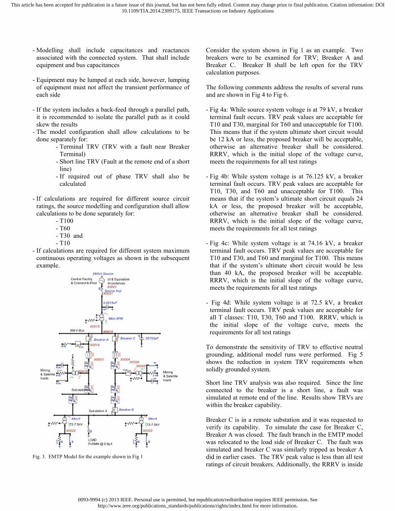
Fig. 3. EMTP Model for the example shown in Fig 1
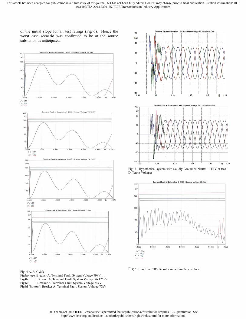
Consider the system shown in Fig 1 as an example. Two breakers were to be examined for TRV; Breaker A and Breaker C. Breaker B shall be left open for the TRV calculation purposes. The following comments address the results of several runs and are shown in Fig 4 to Fig 6. - Fig 4a: While source system voltage is at 79 kV, a breaker
terminal fault occurs. TRV peak values are acceptable for T10 and T30, marginal for T60 and unacceptable for T100. This means that if the system ultimate short circuit would be 12 kA or less, the proposed breaker will be acceptable, otherwise an alternative breaker shall be considered. RRRV, which is the initial slope of the voltage curve, meets the requirements for all test ratings
- Fig 4b: While system voltage is at 76.125 kV, a breaker
terminal fault occurs. TRV peak values are acceptable for T10, T30, and T60 and unacceptable for T100. This means that if the system’s ultimate short circuit equals 24 kA or less, the proposed breaker will be acceptable, otherwise an alternative breaker shall be considered. RRRV, which is the initial slope of the voltage curve, meets the requirements for all test ratings
- Fig 4c: While system voltage is at 74.16 kV, a breaker terminal fault occurs. TRV peak values are acceptable for T10 and T30, and T60 and marginal for T100. This means that if the system’s ultimate short circuit would be less than 40 kA, the proposed breaker will be acceptable. RRRV, which is the initial slope of the voltage curve, meets the requirements for all test ratings
- Fig 4d: While system voltage is at 72.5 kV, a breaker
terminal fault occurs. TRV peak values are acceptable for all T classes: T10, T30, T60 and T100. RRRV, which is the initial slope of the voltage curve, meets the requirements for all test ratings
To demonstrate the sensitivity of TRV to effective neutral grounding, additional model runs were performed. Fig 5 shows the reduction in system TRV requirements when solidly grounded system.
Short line TRV analysis was also required. Since the line connected to the breaker is a short line, a fault was simulated at remote end of the line. Results show TRVs are within the breaker capability. Breaker C is in a remote substation and it was requested to verify its capability. To simulate the case for Breaker C, Breaker A was closed. The fault branch in the EMTP model was relocated to the load side of Breaker C. The fault was simulated and breaker C was similarly tripped as breaker A did in earlier cases. The TRV peak value is less than all test ratings of circuit breakers. Additionally, the RRRV is inside
0093-9994 (c) 2013 IEEE. Personal use is permitted, but republication/redistribution requires IEEE permission. Seehttp://www.ieee.org/publications_standards/publications/rights/index.html for more information.
This article has been accepted for publication in a future issue of this journal, but has not been fully edited. Content may change prior to final publication. Citation information: DOI10.1109/TIA.2014.2309175, IEEE Transactions on Industry Applications
of the initial slope for all test ratings (Fig 6). Hence the worst case scenario was confirmed to be at the source substation as anticipated.
Fig. 4 A, B, C &D Fig4a (top): Breaker A, Terminal Fault, System Voltage 79kV Fig4b : Breaker A, Terminal Fault, System Voltage 76.125kV Fig4c : Breaker A, Terminal Fault, System Voltage 74kV Fig4d (Bottom): Breaker A, Terminal Fault, System Voltage 72kV
Fig. 5. Hypothetical system with Solidly Grounded Neutral - TRV at two Different Voltages
Fig 6. Short line TRV Results are within the envelope
0093-9994 (c) 2013 IEEE. Personal use is permitted, but republication/redistribution requires IEEE permission. Seehttp://www.ieee.org/publications_standards/publications/rights/index.html for more information.
This article has been accepted for publication in a future issue of this journal, but has not been fully edited. Content may change prior to final publication. Citation information: DOI10.1109/TIA.2014.2309175, IEEE Transactions on Industry Applications
IV. CONCLUSION If industrial system operating voltages are out of typical
range, Transient Recovery Voltage (TRV) analysis is critical for breakers performance verifications. In industrial and mining supply systems, where supply transformer neutral might not be solidly grounded such verification become more critical. Use of the updated IEEE Standards in combination with the appropriate EMTP (ATP) system models and runs will allow completion of the analysis and appropriate selection of breaker. An example of a 72.5 kV distribution system was discussed and demonstrated to assist preparation of TRV study cases for similar systems.
V. REFERENCES
1. C.L. Wagner, D. Dufournet, G.F. Montilllet “Revision of the
Application Guide for Transient Recovery Voltage for AC High-Voltage Circuit Breakers of IEEE C37.011: A Working Group Paper of the High Voltage Circuit Breaker Subcommittee” IEEE Transactions on Power Delivery, Vol. 22, No. 1, Jan 2007
2. R.W.Alexander and D.Dufournet, Alstom T&D Tutorial on “TRANSIENT RECOVERY VOLTAGE (TRV) FOR HIGH-VOLTAGE CIRCUIT BREAKERS” Tutorial IEEE Switchgear Committee, St. Pete Beach, May 2003.7
3. IEEE Std. C37.011-2005IEEE “Application Guide for Transient Recovery Voltage for AC High- Voltage Circuit
Breakers”, IEEE, 3Park Ave., NY,NY 10016-5997, USA,
4. IEEE Std. C37.06-2009, “IEEE Standard for AC High-Voltage Circuit Breakers Rated on a Symmetrical Current Basis – Preferred Ratings and Related Required Capabilities
for Voltages above 1000V”, IEEE, 3Park Ave., NY,NY 10016-
5997, USA, 5. IEEE Std. C37.04-1999(R2006) “IEEE Standard Rating
Structure for AC High-Voltage Circuit Breakers”. IEEE, 3Park Ave., NY,NY 10016-5997, USA,
6. IEEE Std. C37.04, “IEEE Standard Rating Structure for AC High Voltage Circuit Breakers Rated on Symmetrical Current Basis, Amendment 2: To Change the Description of Transient
Recovery Voltage for Harmonization with IEC 62271-100”, IEEE, 3Park Ave., NY,NY 10016-5997, USA,
7. IEC publication 60056 (Ed 4.0b), 1987, “High-Voltage
Alternating Current Circuit Breakers”. 8. IEC Publication 62271-100 (Ed. 2), 2008, “High Voltage
Switchgear and Control Gear- Part 100, Alternating Current
Circuit Breakers” 9. ATP Rule Book, Alternative Transient Program Rule Book.
Can/Am User Group 1993 10. R. Rudenberg & G. McKay, “ Transient Performance of
Electric Power Systems- Phenomena in Lumped Networks”Book, McGraw-Hill Book Company Inc., First Edition, 1950
11. J.A. Martinez-Velasco, Editor ”Power System Transients Parameter Determination – Chapter 7” Book, CRC Press 2010