Embed Size (px)
Citation preview

182
2
Circulators
TLC SERIESCirculators for residential systems with threaded connections
TLCB SERIESCirculators for sanitary systems
TLCH SERIESCirculators for commercial systems
TLCHB SERIESCirculators for residential systems
TLCSOL SERIESCirculators for solar systems
TLCK SERIESCirculators for water circulation in cooling, air-conditioning and geothermal systems
FLC-FCT SERIESIn-line close-coupled single- and twin-rotor circulators in cast iron
EFLC-EFLCG SERIESVariable speed circulators for commercial systems
EA+ (ECOCIRC+ AUTO) SERIESA Class high effi ciency variable speed circulators
EV+ (ECOCIRC+ VARIO) SERIESHigh effi ciency variables speed circulators
EB (V) (ECOCIRC BRONZE) SERIESHigh effi ciency electronic circulators for hot water recirculation
FC-FCT SERIESIn-line close-coupled single- and twin-rotor circulators in cast iron
2
183
187
190
193
196
199
203
229
238
241
244
254
Sezione_02_uk.indd 182Sezione_02_uk.indd 182 07/03/12 16.1307/03/12 16.13
183
2
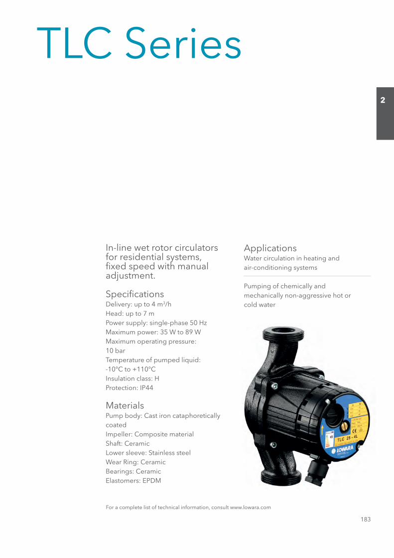
TLC Series
In-line wet rotor circulators for residential systems, fi xed speed with manual adjustment.
Specifi cationsDelivery: up to 4 m3/hHead: up to 7 mPower supply: single-phase 50 HzMaximum power: 35 W to 89 WMaximum operating pressure:10 barTemperature of pumped liquid:-10°C to +110°CInsulation class: HProtection: IP44
MaterialsPump body: Cast iron cataphoreticallycoatedImpeller: Composite materialShaft: CeramicLower sleeve: Stainless steelWear Ring: CeramicBearings: CeramicElastomers: EPDM
ApplicationsWater circulation in heating andair-conditioning systems
Pumping of chemically andmechanically non-aggressive hot orcold water
For a complete list of technical information, consult www.lowara.com
Sezione_02_uk.indd 183Sezione_02_uk.indd 183 07/03/12 16.1307/03/12 16.13

184
2
TLC SERIES Hydraulic performance table
DEEPSMUMIXAMMUMIXAMPMUP
TYPE ABSORBED ABSORBED l/s 0 0,2 0,3 0,5 0,6 0,7 0,8 0,9 1,1
TNERRUCREWOP m3/h 0 0,6 1,2 1,7 2,0 2,4 2,8 3,2 3,9
230V 50Hz W A μF V
8,01,15,10,21,2121,0725.2-51 CLTTLC 25-2.5L 32 0,14 1,5 400 2 2,3 2,1 1,7 1,3 1,1
9,02,15,19,13,25,2351,053L5.2-23 CLT8,02,18,17,25,3141,0334-51 CLT
TLC 25-4 (L) 39 0,17 1,5 400 2 3,9 3,2 2,4 1,9 1,6 1,19,05,19,12,28,25,32,4391,044L4-23 CLT
8,03,10,29,29,3191,0345-51 CLTTLC 25-5 (L) 63 0,28 2,0 400 2 4,8 4,3 3,7 3,0 2,5 1,8 0,9
8,13,20,35,38,34,49,42,5343,077L5-23 CLT9,05,13,24,3191,0346-51 CLT
TLC 25-6 (L) 65 0,28 2,0 400 2 5,2 4,1 3,0 2,1 1,7 1,18,14,20,36,30,47,46,52,6343,008L6-23 CLT
4,09,04,17,15,26,34,5142,0457-51 CLTTLC 25-7L 76 0,34 2,0 400 2 6,6 5,5 4,0 2,9 2,3 1,6 1,0 0,4
4,00,29,29,37,42,59,56,61,7393,098L7-23 CLTPerformances according to standards EN 1151-1 tlc-2p50-en_b_th
H = TOTAL HEAD METRES COLUMN OF WATER
Q = DELIVERYCAPACITOR
TLC SERIES Dimensions and weights
TLC SERIES Dimensions and weights table
PUMP TYPE WEIGHT
H H1 D F DN kg
TLC 15-2.5 130 65 1/2" G 1" 15 2,6 TLC 25-2.5L 180 90 1" G 1"½ 25 2,7 TLC 32-2.5L 180 90 1"¼ G 2" 32 2,8 TLC 15-4 130 65 1/2" G 1" 15 2,6 TLC 25-4 130 65 1" G 1"½ 25 2,7 TLC 25-4L 180 90 1" G 1"½ 25 2,7 TLC 32-4L 180 90 1"¼ G 2" 32 2,8 TLC 15-5 130 65 1/2" G1" 15 2,6 TLC 25-5 130 65 1" G 1"½ 25 2,7 TLC 25-5L 180 90 1" G 1"½ 25 2,7 TLC 32-5L 180 90 1"¼ G 2" 32 2,8 TLC 15-6 130 65 1/2" G 1" 15 2,6 TLC 25-6 130 65 1" G 1"½ 25 2,7 TLC 25-6L 180 90 1" G 1"½ 25 2,8 TLC 32-6L 180 90 1"¼ G 2" 32 2,8 TLC 15-7 130 65 1/2" G 1" 15 2,6 TLC 25-7L 180 90 1" G 1"½ 25 2,8 TLC 32-7L 180 90 1"¼ G 2" 32 2,8
tlc-2p50-en_c_td
DIMENSIONS (mm)
Sezione_02_uk.indd 184Sezione_02_uk.indd 184 07/03/12 16.1307/03/12 16.13
185
2
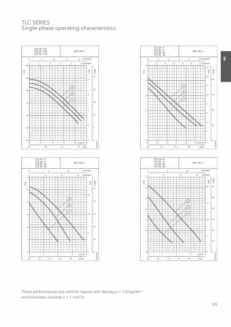
These performances are valid for liquids with density ρ = 1.0 kg/dm3 and kinematic viscosity ν = 1 mm2/s.
TLC SERIESSingle-phase operating characteristics
Sezione_02_uk.indd 185Sezione_02_uk.indd 185 07/03/12 16.1307/03/12 16.13

186
2
These performances are valid for liquids with density ρ = 1.0 kg/dm3 and kinematic viscosity ν = 1 mm2/s.
TLC SERIESSingle-phase operating characteristics
Black and white technical books available
see www.lowara.it
Sezione_02_uk.indd 186Sezione_02_uk.indd 186 07/03/12 16.1307/03/12 16.13
187
2
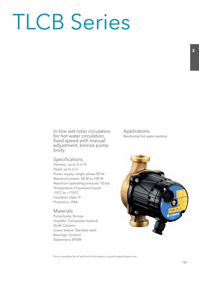
TLCB Series
In-line wet rotor circulators for hot water circulation, fi xed speed with manual adjustment, bronze pump body.
Specifi cationsDelivery: up to 5 m3/hHead: up to 6 mPower supply: single-phase 50 HzMaximum power: 58 W to 100 WMaximum operating pressure: 10 barTemperature of pumped liquid:-10°C to +110°CInsulation class: HProtection: IP44
MaterialsPump body: BronzeImpeller: Composite materialShaft: CeramicLower sleeve: Stainless steelBearings: CeramicElastomers: EPDM
ApplicationsResidential hot water systems
For a complete list of technical information, consult www.lowara.com
Sezione_02_uk.indd 187Sezione_02_uk.indd 187 07/03/12 16.1307/03/12 16.13
188
2
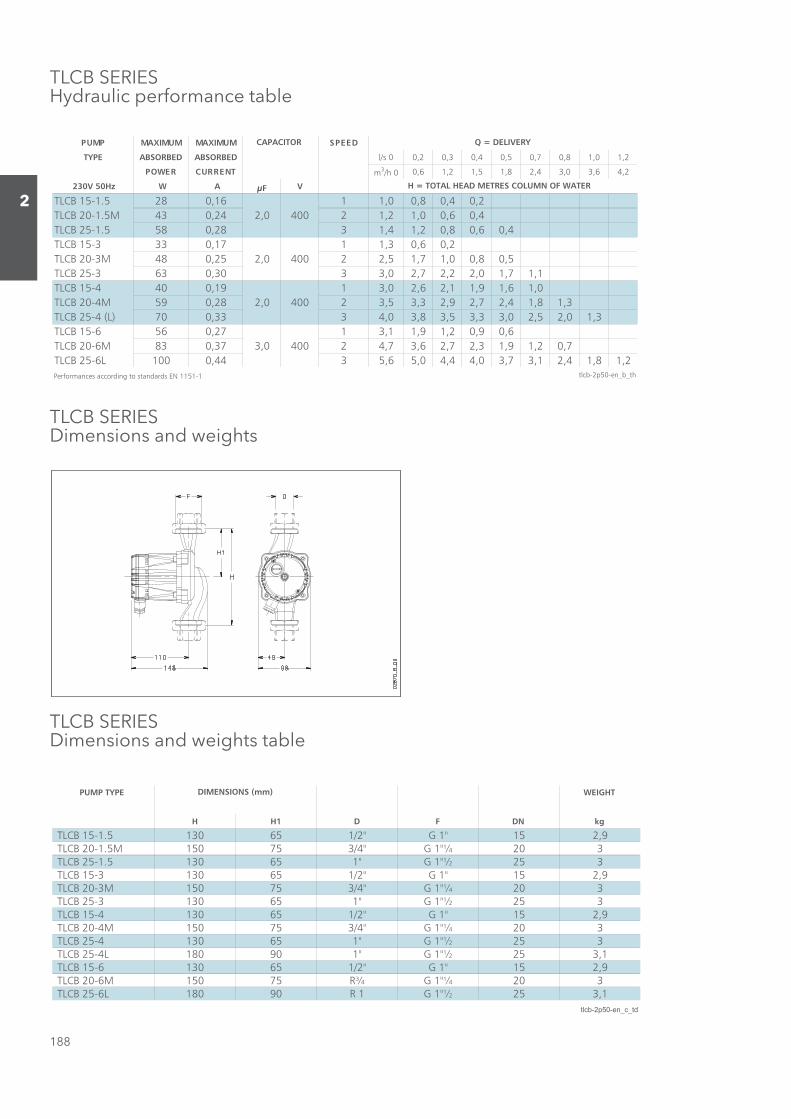
TLCB SERIESHydraulic performance table
TLCB SERIES Dimensions and weights
TLCB SERIES Dimensions and weights table
DEEPSMUMIXAMMUMIXAMPMUP
TYPE ABSORBED ABSORBED l/s 0 0,2 0,3 0,4 0,5 0,7 0,8 1,0 1,2
TNERRUCREWOP m3/h 0 0,6 1,2 1,5 1,8 2,4 3,0 3,6 4,2
230V 50Hz W A μF V
2,04,08,00,1161,0825.1-51 BCLTTLCB 20-1.5M 43 0,24 2,0 400 2 1,2 1,0 0,6 0,4
4,06,08,02,14,1382,0855.1-52 BCLT2,06,03,1171,0333-51 BCLT
TLCB 20-3M 48 0,25 2,0 400 2 2,5 1,7 1,0 0,8 0,51,17,10,22,27,20,3303,0363-52 BCLT0,16,19,11,26,20,3191,0044-51 BCLT
TLCB 20-4M 59 0,28 2,0 400 2 3,5 3,3 2,9 2,7 2,4 1,8 1,33,10,25,20,33,35,38,30,4333,007)L( 4-52 BCLT
6,09,02,19,11,3172,0656-51 BCLTTLCB 20-6M 83 0,37 3,0 400 2 4,7 3,6 2,7 2,3 1,9 1,2 0,7
2,18,14,21,37,30,44,40,56,5344,0001L6-52 BCLTPerformances according to standards EN 1151-1 tlcb-2p50-en_b_th
H = TOTAL HEAD METRES COLUMN OF WATER
Q = DELIVERYCAPACITOR
PUMP TYPE WEIGHT
H H1 D F DN kg
TLCB 15-1.5 130 65 1/2" G 1" 15 2,9 TLCB 20-1.5M 150 75 3/4" G 1"¼ 20 3 TLCB 25-1.5 130 65 1" G 1"½ 25 3 TLCB 15-3 130 65 1/2" G 1" 15 2,9 TLCB 20-3M 150 75 3/4" G 1"¼ 20 3 TLCB 25-3 130 65 1" G 1"½ 25 3 TLCB 15-4 130 65 1/2" G 1" 15 2,9 TLCB 20-4M 150 75 3/4" G 1"¼ 20 3 TLCB 25-4 130 65 1" G 1"½ 25 3 TLCB 25-4L 180 90 1" G 1"½ 25 3,1 TLCB 15-6 130 65 1/2" G 1" 15 2,9 TLCB 20-6M 150 75 R¾ G 1"¼ 20 3 TLCB 25-6L 180 90 R 1 G 1"½ 25 3,1
tlcb-2p50-en_c_td
DIMENSIONS (mm)
Sezione_02_uk.indd 188Sezione_02_uk.indd 188 07/03/12 16.1307/03/12 16.13

189
2
TLCB SERIESSingle-phase operating characteristiques
These performances are valid for liquids with density ρ = 1.0 kg/dm3 and kinematic viscosity ν = 1 mm2/s.
Sezione_02_uk.indd 189Sezione_02_uk.indd 189 07/03/12 16.1307/03/12 16.13
190
2
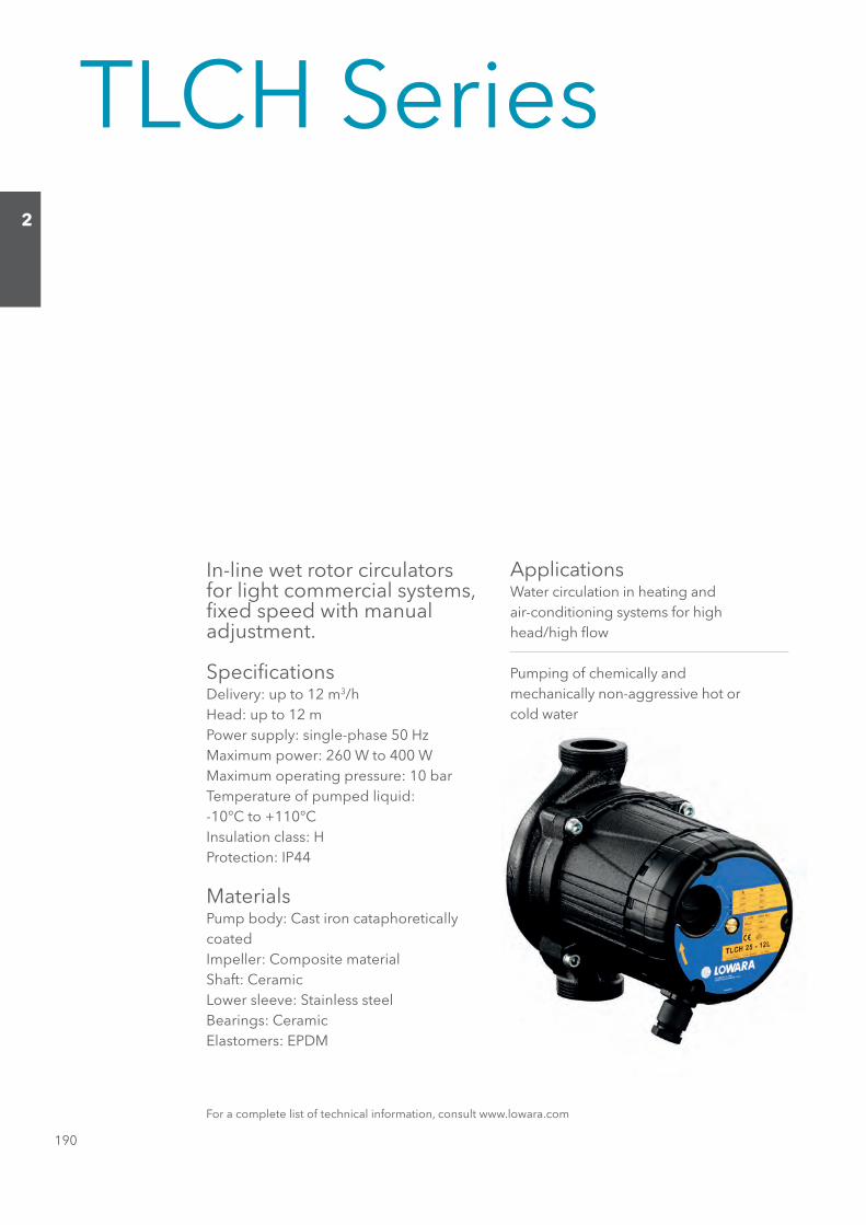
TLCH Series
In-line wet rotor circulators for light commercial systems, fi xed speed with manual adjustment.
Specifi cationsDelivery: up to 12 m3/hHead: up to 12 mPower supply: single-phase 50 HzMaximum power: 260 W to 400 WMaximum operating pressure: 10 barTemperature of pumped liquid:-10°C to +110°CInsulation class: HProtection: IP44
MaterialsPump body: Cast iron cataphoreticallycoatedImpeller: Composite materialShaft: CeramicLower sleeve: Stainless steelBearings: CeramicElastomers: EPDM
ApplicationsWater circulation in heating andair-conditioning systems for highhead/high fl ow
Pumping of chemically andmechanically non-aggressive hot orcold water
For a complete list of technical information, consult www.lowara.com
Sezione_02_uk.indd 190Sezione_02_uk.indd 190 07/03/12 16.1307/03/12 16.13
191
2
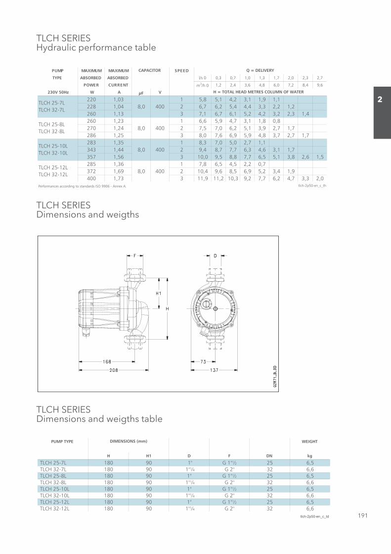
TLCH SERIES Hydraulic performance table
TLCH SERIES Dimensions and weigths
TLCH SERIES Dimensions and weigths table
DEEPSMUMIXAMMUMIXAMPMUP
TYPE ABSORBED ABSORBED l/s 0 0,3 0,7 1,0 1,3 1,7 2,0 2,3 2,7
TNERRUCREWOP m3/h 0 1,2 2,4 3,6 4,8 6,0 7,2 8,4 9,6
230V 50Hz W A μF V
1,19,11,32,41,58,5130,1022228 1,04 8,0 400 2 6,7 6,2 5,4 4,4 3,3 2,2 1,2
4,13,22,32,42,51,67,61,7331,10628,08,11,37,49,56,6132,1062
270 1,24 8,0 400 2 7,5 7,0 6,2 5,1 3,9 2,7 1,77,17,27,38,49,59,66,70,8352,1682
1,17,20,50,73,8153,1382343 1,44 8,0 400 2 9,4 8,7 7,7 6,3 4,6 3,1 1,7
5,16,28,31,55,67,78,85,90,01365,17537,02,25,45,68,7163,1582
372 1,69 8,0 400 2 10,4 9,6 8,5 6,9 5,2 3,4 1,90,23,37,42,67,72,93,012,119,11337,1004
Performances according to standards ISO 9906 - Annex A. tlch-2p50-en_c_th
TLCH 25-10L TLCH 32-10L
TLCH 25-12L TLCH 32-12L
H = TOTAL HEAD METRES COLUMN OF WATER
Q = DELIVERYCAPACITOR
TLCH 25-7L TLCH 32-7L
TLCH 25-8L TLCH 32-8L
PUMP TYPE WEIGHT
H H1 D F DN kg
TLCH 25-7L 180 90 1" G 1"½ 25 6,5 TLCH 32-7L 180 90 1"¼ G 2" 32 6,6 TLCH 25-8L 180 90 1" G 1"½ 25 6,5 TLCH 32-8L 180 90 1"¼ G 2" 32 6,6 TLCH 25-10L 180 90 1" G 1"½ 25 6,5 TLCH 32-10L 180 90 1"¼ G 2" 32 6,6 TLCH 25-12L 180 90 1" G 1"½ 25 6,5 TLCH 32-12L 180 90 1"¼ G 2" 32 6,6
tlch-2p50-en_c_td
DIMENSIONS (mm)
Sezione_02_uk.indd 191Sezione_02_uk.indd 191 07/03/12 16.1307/03/12 16.13
192
2
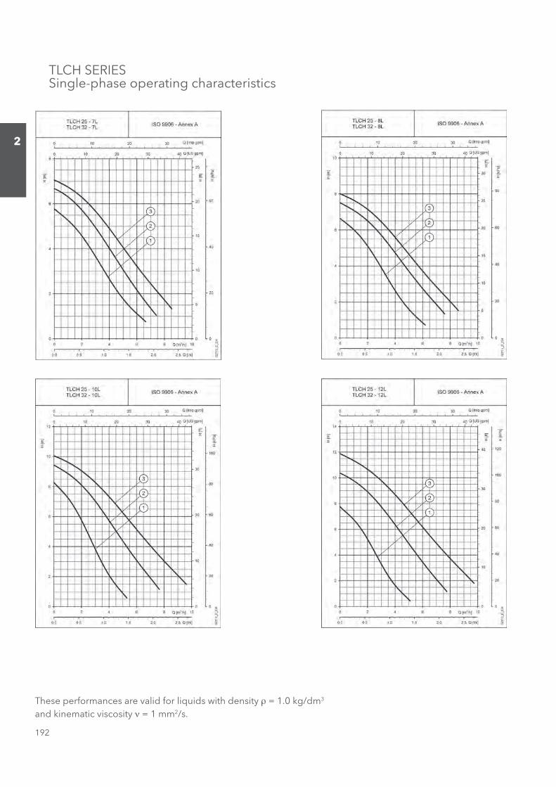
TLCH SERIESSingle-phase operating characteristics
These performances are valid for liquids with density ρ = 1.0 kg/dm3 and kinematic viscosity ν = 1 mm2/s.
Sezione_02_uk.indd 192Sezione_02_uk.indd 192 07/03/12 16.1307/03/12 16.13
193
2
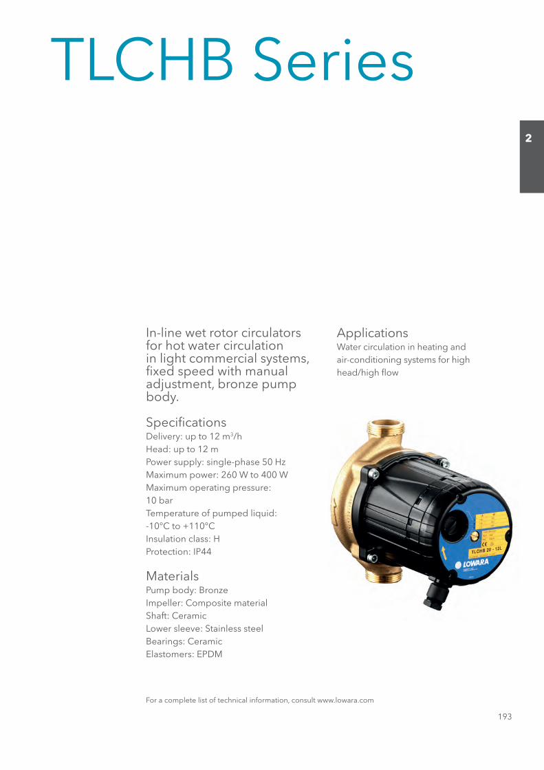
TLCHB Series
In-line wet rotor circulators for hot water circulation in light commercial systems, fi xed speed with manual adjustment, bronze pump body.
Specifi cationsDelivery: up to 12 m3/hHead: up to 12 mPower supply: single-phase 50 HzMaximum power: 260 W to 400 WMaximum operating pressure:10 barTemperature of pumped liquid:-10°C to +110°CInsulation class: HProtection: IP44
MaterialsPump body: BronzeImpeller: Composite materialShaft: CeramicLower sleeve: Stainless steelBearings: CeramicElastomers: EPDM
ApplicationsWater circulation in heating andair-conditioning systems for highhead/high fl ow
For a complete list of technical information, consult www.lowara.com
Sezione_02_uk.indd 193Sezione_02_uk.indd 193 07/03/12 16.1307/03/12 16.13

194
2
TLCHB SERIES Hydraulic performance table
TLCHB SERIES Dimensions and weights
TLCHB SERIES Dimensions and weights table
DEEPSMUMIXAMMUMIXAMPMUP
TYPE ABSORBED ABSORBED l/s 0 0,3 0,7 1,0 1,3 1,7 2,0 2,3 2,7
TNERRUCREWOP m3/h 0 1,2 2,4 3,6 4,8 6,0 7,2 8,4 9,6
230V 50Hz W A μF V
1,19,11,32,41,58,5130,1022228 1,04 8,0 400 2 6,7 6,2 5,4 4,4 3,3 2,2 1,2
4,13,22,32,42,51,67,61,7331,10628,08,11,37,49,56,6132,1062
270 1,24 8,0 400 2 7,5 7,0 6,2 5,1 3,9 2,7 1,77,17,27,38,49,59,66,70,8352,1682
1,17,20,50,73,8153,1382343 1,44 8,0 400 2 9,4 8,7 7,7 6,3 4,6 3,1 1,7
5,16,28,31,55,67,78,85,90,01365,17537,02,25,45,68,7163,1582
372 1,69 8,0 400 2 10,4 9,6 8,5 6,9 5,2 3,4 1,90,23,37,42,67,72,93,012,119,11337,1004
Performances according to standards ISO 9906 - Annex A. tlchb-2p50-en_c_th
TLCHB 20-10L TLCHB 25-10L
TLCHB 20-12L TLCHB 25-12L
H = TOTAL HEAD METRES COLUMN OF WATER
Q = DELIVERYCAPACITOR
TLCHB 20-7L TLCHB 25-7L
TLCHB 20-8L TLCHB 25-8L
PUMP TYPE WEIGHT
H H1 D F DN kg
TLCHB 20-7L 180 90 3/4" G 1"¼ 20 6,7 TLCHB 25-7L 180 90 1" G 1"½ 25 6,7 TLCHB 20-8L 180 90 3/4" G 1"¼ 20 6,7 TLCHB 25-8L 180 90 1" G 1"½ 25 6,7 TLCHB 20-10L 180 90 3/4" G 1"¼ 20 6,7 TLCHB 25-10L 180 90 1" G 1"½ 25 6,7 TLCHB 20-12L 180 90 3/4" G 1"¼ 20 6,7 TLCHB 25-12L 180 90 1" G 1"½ 25 6,7
tlchb-2p50-en_c_td
DIMENSIONS (mm)
Sezione_02_uk.indd 194Sezione_02_uk.indd 194 07/03/12 16.1307/03/12 16.13

195
2
These performances are valid for liquids with density ρ = 1.0 kg/dm3 and kinematic viscosity ν = 1 mm2/s.
TLCHB SERIESSingle-phase operating characteristics
Sezione_02_uk.indd 195Sezione_02_uk.indd 195 07/03/12 16.1307/03/12 16.13
196
2
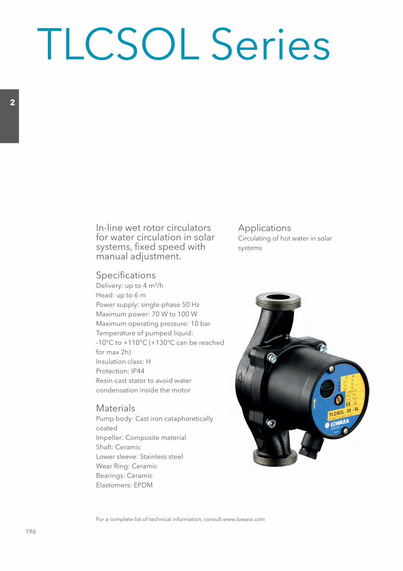
TLCSOL Series
In-line wet rotor circulators for water circulation in solar systems, fi xed speed with manual adjustment.
Specifi cationsDelivery: up to 4 m3/hHead: up to 6 mPower supply: single-phase 50 HzMaximum power: 70 W to 100 WMaximum operating pressure: 10 barTemperature of pumped liquid:-10°C to +110°C (+130°C can be reachedfor max 2h)Insulation class: HProtection: IP44Resin-cast stator to avoid watercondensation inside the motor
MaterialsPump body: Cast iron cataphoreticallycoatedImpeller: Composite materialShaft: CeramicLower sleeve: Stainless steelWear Ring: CeramicBearings: CeramicElastomers: EPDM
ApplicationsCirculating of hot water in solarsystems
For a complete list of technical information, consult www.lowara.com
Sezione_02_uk.indd 196Sezione_02_uk.indd 196 07/03/12 16.1307/03/12 16.13

197
2
TLCSOL SERIES Hydraulic performance table
TLCSOL SERIES Dimensions and weights
TLCSOL SERIES Dimensions and weights table
DEEPSMUMIXAMMUMIXAMPMUP
TYPE ABSORBED ABSORBED l/s 0 0,2 0,3 0,4 0,5 0,7 0,8 1,0 1,2
TNERRUCREWOP m3/h 0 0,6 1,2 1,5 1,8 2,4 3,0 3,6 4,2
230V 50Hz W A μF V
0,16,19,11,26,29,2191,00459 0,28 2,0 400 2 3,5 3,2 2,9 2,6 2,4 1,8 1,2
3,10,25,20,33,34,38,30,4333,0076,09,02,18,10,3172,065
83 0,37 3,0 400 2 4,7 3,6 2,7 2,3 1,9 1,2 0,72,18,14,20,37,30,43,40,57,5344,0001
Performances according to standards EN 1151-1 tlcsol-2p50-en_b_th
TLCSOL 15-4 TLCSOL 25-4L
TLCSOL 15-6 TLCSOL 25-6L
H = TOTAL HEAD METRES COLUMN OF WATER
Q = DELIVERYCAPACITOR
PUMP TYPE WEIGHT
H H1 D F DN kg
TLCSOL 15-4 130 65 1/2" G 1" 15 3 TLCSOL 25-4L 180 90 1" G 1"½ 25 3 TLCSOL 15-6 130 65 1/2" G 1" 15 3 TLCSOL 25-6L 180 90 1" G 1"½ 25 3
tlcsol-2p50-en_c_td
DIMENSIONS (mm)
Sezione_02_uk.indd 197Sezione_02_uk.indd 197 07/03/12 16.1307/03/12 16.13
198
2
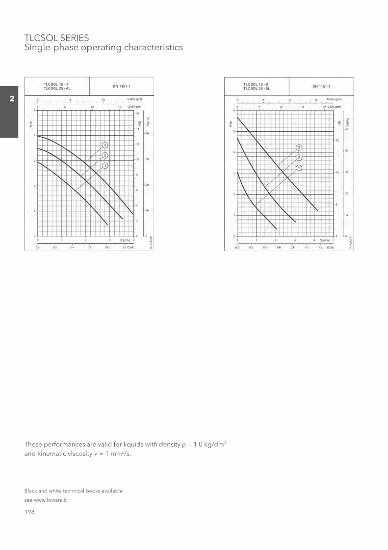
TLCSOL SERIESSingle-phase operating characteristics
These performances are valid for liquids with density ρ = 1.0 kg/dm3 and kinematic viscosity ν = 1 mm2/s.
Black and white technical books available
see www.lowara.it
Sezione_02_uk.indd 198Sezione_02_uk.indd 198 07/03/12 16.1307/03/12 16.13
199
2
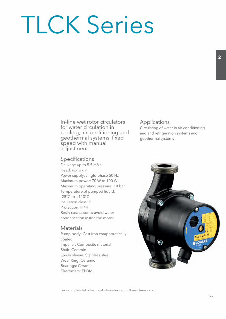
TLCK Series
In-line wet rotor circulators for water circulation in cooling, airconditioning and geothermal systems, fi xed speed with manualadjustment.
Specifi cationsDelivery: up to 5.5 m3/hHead: up to 6 mPower supply: single-phase 50 HzMaximum power: 70 W to 100 WMaximum operating pressure: 10 barTemperature of pumped liquid:-25°C to +110°CInsulation class: HProtection: IP44Resin-cast stator to avoid watercondensation inside the motor
MaterialsPump body: Cast iron cataphoreticallycoatedImpeller: Composite materialShaft: CeramicLower sleeve: Stainless steelWear Ring: CeramicBearings: CeramicElastomers: EPDM
ApplicationsCirculating of water in air-conditioningand and refrigeration systems andgeothermal systems
For a complete list of technical information, consult www.lowara.com
Sezione_02_uk.indd 199Sezione_02_uk.indd 199 07/03/12 16.1307/03/12 16.13

200
2
TLCK SERIES Hydraulic performance table
TLCK SERIES Dimensions and weights
TLCK SERIES Dimensions and weights table
DEEPSMUMIXAMMUMIXAMPMUP
TYPE ABSORBED ABSORBED l/s 0 0,2 0,3 0,4 0,5 0,7 0,8 1,0 1,2
TNERRUCREWOP m3/h 0 0,6 1,2 1,5 1,8 2,4 3,0 3,6 4,2
230V 50Hz W A μF V
0,16,19,11,26,29,2191,004TLCK 25-4L 59 0,28 2,0 400 2 3,5 3,2 2,9 2,6 2,4 1,8 1,2
3,10,25,20,33,34,38,30,4333,0076,09,02,18,10,3172,065
TLCK 25-6L 83 0,37 3,0 400 2 4,7 3,6 2,7 2,3 1,9 1,2 0,72,18,14,20,37,30,43,40,57,5344,0001
Performances according to standards EN 1151-1 tlck-2p50-en_b_th
H = TOTAL HEAD METRES COLUMN OF WATER
Q = DELIVERYCAPACITOR
PUMP TYPE WEIGHT
H H1 D F DN kg
TLCK 25-4L 180 90 1" G 1"½ 25 3 TLCK 25-6L 180 90 1" G 1"½ 25 3
tlck-2p50-en_c_td
DIMENSIONS (mm)
Sezione_02_uk.indd 200Sezione_02_uk.indd 200 07/03/12 16.1307/03/12 16.13

201
2
TLCK SERIESSingle-phase operating characteristics
These performances are valid for liquids with density ρ = 1.0 kg/dm3 and kinematic viscosity ν = 1 mm2/s.
Black and white technical books available
see www.lowara.it
Sezione_02_uk.indd 201Sezione_02_uk.indd 201 07/03/12 16.1307/03/12 16.13
202
2
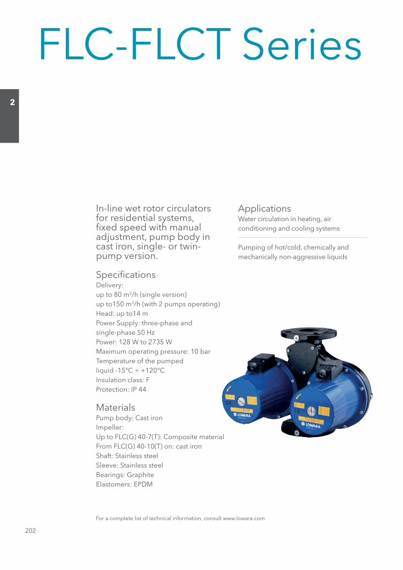
FLC-FLCT Series
In-line wet rotor circulators for residential systems, fi xed speed with manual adjustment, pump body in cast iron, single- or twin-pump version.
Specifi cationsDelivery:up to 80 m3/h (single version)up to150 m3/h (with 2 pumps operating)Head: up to14 mPower Supply: three-phase andsingle-phase 50 HzPower: 128 W to 2735 WMaximum operating pressure: 10 barTemperature of the pumpedliquid -15°C ÷ +120°CInsulation class: FProtection: IP 44
MaterialsPump body: Cast ironImpeller:Up to FLC(G) 40-7(T): Composite materialFrom FLC(G) 40-10(T) on: cast ironShaft: Stainless steelSleeve: Stainless steelBearings: GraphiteElastomers: EPDM
ApplicationsWater circulation in heating, airconditioning and cooling systems
Pumping of hot/cold, chemically andmechanically non-aggressive liquids
For a complete list of technical information, consult www.lowara.com
Sezione_02_uk.indd 202Sezione_02_uk.indd 202 07/03/12 16.1307/03/12 16.13
203
2
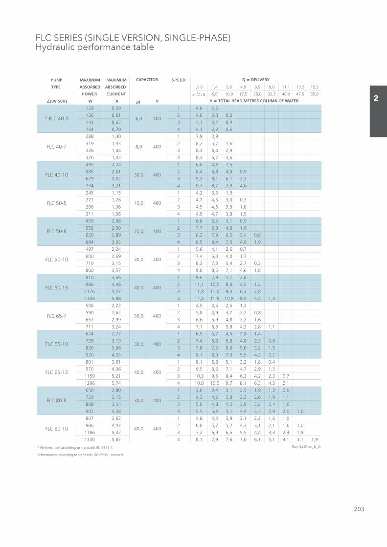
FLC SERIES (SINGLE VERSION, SINGLE-PHASE)Hydraulic performance table
DEEPSMUMIXAMMUMIXAMPMUP
TYPE ABSORBED ABSORBED l/s 0 1,4 2,8 4,9 6,9 9,0 11,1 13,2 15,3
TNERRUCREWOP m3/h 0 5,0 10,0 17,5 25,0 32,5 40,0 47,5 55,0
230V 50Hz W A μF V
5,20,4195,0821
3,00,30,4216,0631
4,02,31,4336,0341
6,03,31,4407,0451
9,39,7103,1882
6,17,52,8234,1913
9,24,63,8344,1623
6,37,63,8434,1623
5,28,48,6142,2094
9,03,48,64,8216,2585
3,21,61,83,9320,3976
0,43,77,87,9412,3437
9,13,32,4151,1542
3,00,33,47,4262,1772
0,15,36,49,4363,1692
5,18,37,49,4465,1113
9,01,32,56,6180,2954
9,19,49,67,7205,2855
8,04,35,69,72,8398,2056
9,19,45,74,85,8430,3486
7,06,21,46,5142,2794
7,10,40,64,7296,2006
3,07,24,53,73,8351,3917
8,16,41,75,80,9475,3008
8,27,59,76,9166,3018
3,15,40,80,011,11264,4689
8,23,64,90,118,11372,56711
4,14,55,88,019,114,21488,56031
3,15,25,35,4132,2605
8,02,27,39,48,5226,2095
6,12,38,49,56,6399,2756
1,18,23,48,56,61,7442,3117
4,18,25,47,55,6177,2426
8,03,20,48,58,64,7291,3527
5,12,30,56,65,78,7366,3628
2,22,49,53,70,81,8433,4029
4,08,12,31,58,61,8116,3108
3,19,27,41,76,85,9263,4079
7,03,22,43,64,86,93,01312,59511
1,23,43,61,87,95,018,01447,56921
6,03,19,15,21,34,36,3108,2056
1,19,16,23,38,32,43,4251,3927
6,14,22,39,35,48,40,5345,3808
0,10,29,27,34,41,54,55,5482,4209
0,16,12,21,39,34,46,4136,3708
0,16,11,21,33,42,57,50,6234,4689
8,14,23,34,45,55,69,62,7323,56811
9,11,31,41,51,60,76,79,71,8478,50331
* Performances according to standards EN 1151-1. flcm-2p50-en_b_th
Performances according to standards ISO 9906 - Annex A.
30,0 400
H = TOTAL HEAD METRES COLUMN OF WATER
Q = DELIVERYCAPACITOR
400
16,0 400
400
* FLC 40-5 400
FLC 65-7
FLC 65-10
FLC 40-7
FLC 40-10
FLC 50-5
FLC 50-8
400
30,0
FLC 65-12
FLC 80-8
FLC 80-10
6,0
8,0
25,0
30,0
30,0
FLC 50-10
FLC 50-13
400
40,0 400
40,0 400
400
30,0 400
40,0 400
Sezione_02_uk.indd 203Sezione_02_uk.indd 203 07/03/12 16.1307/03/12 16.13

204
2
FLC40..T - FLC50..T SERIES (SINGLE VERSION, THREE-PHASE)Hydraulic performance table
PUMP MAXIMUM MAXIMUM SPEED
TYPE ABSORBED ABSORBED l/s 0 0,6 1,1 1,7 2,2 2,8 3,3 3,9 4,4 5,6 6,7 7,8 8,9 10,0 11,1
400V POWER CURRENT m3/h 0 2 4 6 8 10 12 14 16 20 24 28 32 36 40
50Hz W A
105 0,17 1 3,6 3,1 2,5 1,6 0,7
118 0,21 2 3,7 3,3 2,8 2,1 1,1
135 0,25 3 3,9 3,5 3,2 2,5 1,4 0,2
150 0,33 4 3,9 3,7 3,4 2,7 1,7 0,5
209 0,33 1 7,5 5,5 4,6 3,3 1,9 0,7
252 0,40 2 7,8 6,3 5,5 4,3 2,9 1,5 0,1
296 0,49 3 8,1 6,9 6,3 5,4 4,1 2,5 1,0
336 0,61 4 8,3 7,4 7,0 6,3 5,1 3,6 2,0 0,1
471 0,77 1 7,8 7,0 6,4 5,8 5,0 4,1 3,1 2,3 1,5
570 0,92 2 8,5 7,9 7,4 6,9 6,2 5,4 4,5 3,5 2,6 0,9
645 1,03 3 9,0 8,7 8,2 7,7 7,1 6,4 5,7 4,9 4,0 2,0
699 1,17 4 9,5 9,2 8,8 8,4 7,9 7,3 6,6 5,9 5,0 3,1 1,0
221 0,43 1 4,3 4,1 3,8 3,3 2,8 2,2 1,6 1,0 0,2
264 0,51 2 4,5 4,5 4,2 3,8 3,4 2,9 2,4 1,7 1,0
304 0,62 3 4,7 4,8 4,6 4,2 3,9 3,5 3,0 2,4 1,7
334 0,78 4 4,8 5,0 4,8 4,5 4,2 3,8 3,4 2,8 2,2 0,5
495 0,80 1 6,9 6,7 6,5 6,1 5,6 4,9 4,2 3,4 2,6 1,2
550 0,88 2 7,6 7,5 7,3 6,9 6,4 5,8 5,1 4,4 3,6 2,1 0,7
621 1,00 3 8,2 8,1 8,0 7,7 7,3 6,9 6,3 5,6 4,9 3,2 1,5
669 1,13 4 8,5 8,5 8,5 8,3 8,0 7,6 7,1 6,5 5,8 4,2 2,4 0,8
508 0,83 1 6,9 6,6 6,0 5,4 4,7 4,1 3,5 2,9 2,3 1,2
622 1,00 2 7,9 7,7 7,3 6,7 6,1 5,5 4,8 4,2 3,5 2,2 0,9
724 1,17 3 8,6 8,5 8,2 7,7 7,1 6,5 5,8 5,2 4,5 3,2 1,7 0,3
822 1,39 4 9,4 9,4 9,2 8,8 8,3 7,7 7,1 6,5 5,8 4,5 2,9 1,2
852 1,39 1 10,6 10,2 9,7 9,1 8,4 7,7 6,9 6,2 5,5 3,9
1017 1,68 2 11,6 11,4 11,0 10,5 9,9 9,3 8,6 7,8 7,0 5,4 3,7 1,8
1180 1,94 3 12,4 12,2 11,9 11,5 11,0 10,4 9,8 9,2 8,4 6,9 5,1 3,2 1,1
1338 2,40 4 13,2 13,2 13,0 12,7 12,3 11,8 11,2 10,6 9,9 8,4 6,7 4,7 2,5
1507 2,40 1 16,5 16,6 16,2 15,6 14,9 14,1 13,2 12,3 11,4 9,4 7,1 4,4 1,6
1768 2,80 2 17,8 18,0 17,8 17,4 16,8 16,1 15,3 14,4 13,6 11,7 9,6 7,0 4,1 1,0
2017 3,20 3 18,7 19,0 19,0 18,7 18,3 17,7 17,0 16,3 15,5 13,7 11,7 9,2 6,4 3,2
2232 3,66 4 19,6 20,0 20,0 19,8 19,5 19,0 18,5 17,9 17,2 15,7 13,8 11,4 8,6 5,4 1,8
* Performances according to standards EN 1151-1. flct-1-2p50-en_b_th
Performances according to standards ISO 9906 - Annex A.
Q = DELIVERY
H = TOTAL HEAD METRES COLUMN OF WATER
FLC 50-13T
FLC 50-18T
FLC 40-10T
FLC 50-5T
FLC 50-8T
FLC 50-10T
* FLC 40-5T
FLC 40-7T
Sezione_02_uk.indd 204Sezione_02_uk.indd 204 07/03/12 16.1307/03/12 16.13

205
2
FLC65..T - FLC80..T SERIES (SINGLE VERSION, THREE-PHASE)Hydraulic performance table
PUMP MAXIMUM MAXIMUM SPEED
TYPE ABSORBED ABSORBED l/s 0 1,4 2,8 4,2 5,6 6,9 8,3 9,7 11,1 12,5 13,9 15,3 16,7 19,4 22,2
400V POWER CURRENT m3/h 0 5 10 15 20 25 30 35 40 45 50 55 60 70 80
50Hz W A
458 0,73 1 5,3 4,5 3,6 2,7 1,8 0,8
547 0,89 2 5,9 5,2 4,2 3,3 2,4 1,3
628 1,02 3 6,5 6,0 5,1 4,2 3,2 2,1 0,9
702 1,22 4 7,0 6,6 5,9 5,0 4,0 2,9 1,6
640 1,04 1 7,1 6,3 5,2 4,2 3,2 2,1 1,0
761 1,24 2 7,8 7,2 6,2 5,2 4,2 3,0 1,8 0,6
874 1,45 3 8,4 8,0 7,1 6,1 5,0 3,8 2,6 1,2
1020 1,97 4 9,0 8,7 7,9 6,9 5,9 4,7 3,4 2,0
892 1,43 1 9,1 8,3 7,1 5,9 4,8 3,6 2,4 1,2
1070 1,70 2 10,1 9,6 8,6 7,4 6,2 5,0 3,8 2,4 1,0
1229 1,96 3 10,9 10,5 9,6 8,5 7,4 6,2 4,9 3,5 2,0
1385 2,32 4 11,8 11,6 10,9 9,9 8,7 7,6 6,3 4,9 3,3 1,6
1424 2,26 1 13,0 12,4 11,4 10,2 8,8 7,4 5,9 4,3 2,6 0,8
1651 2,61 2 14,0 13,6 12,8 11,7 10,5 9,0 7,5 6,0 4,2 2,4
1862 2,95 3 14,8 14,6 13,9 13,0 11,8 10,5 9,0 7,4 5,6 3,7 1,5
2029 3,37 4 15,3 15,4 14,9 14,0 12,9 11,6 10,2 8,7 6,9 5,0 2,8
629 1,03 1 4,0 3,9 3,6 3,2 2,8 2,3 1,9 1,4 0,9
765 1,23 2 4,9 4,8 4,5 4,1 3,6 3,1 2,6 2,0 1,5 0,9
884 1,46 3 5,5 5,4 5,1 4,7 4,2 3,7 3,2 2,6 2,1 1,4
1033 1,97 4 6,2 6,1 5,8 5,4 4,9 4,3 3,8 3,2 2,6 1,9 1,2
889 1,45 1 6,1 5,9 5,5 5,0 4,4 3,9 3,3 2,7 2,1 1,4
1086 1,73 2 7,1 7,0 6,6 6,2 5,6 5,1 4,5 3,9 3,3 2,6 1,8
1238 1,99 3 7,9 7,8 7,5 7,1 6,5 6,0 5,3 4,7 4,1 3,4 2,7 2,0
1390 2,35 4 8,8 8,7 8,5 8,1 7,6 7,0 6,4 5,8 5,1 4,4 3,7 2,9 2,0
1393 2,21 1 8,8 8,5 8,1 7,6 7,0 6,5 5,8 5,2 4,5 3,8 3,1 2,4 1,7
1611 2,54 2 9,7 9,4 9,1 8,7 8,2 7,7 7,0 6,4 5,7 4,9 4,2 3,4 2,6
1806 2,88 3 10,5 10,3 10,0 9,6 9,1 8,6 8,0 7,3 6,7 5,9 5,2 4,3 3,5 1,6
2005 3,35 4 11,4 11,3 11,0 10,7 10,2 9,7 9,1 8,4 7,7 6,9 6,1 5,3 4,4 2,3
1647 2,62 1 10,2 9,7 9,2 8,7 8,1 7,4 6,7 6,0 5,3 4,6 4,0 3,3 2,7
1959 3,09 2 11,4 11,0 10,7 10,2 9,7 9,1 8,5 7,7 7,0 6,2 5,5 4,7 4,0 2,5
2263 3,58 3 12,5 12,2 11,9 11,6 11,1 10,6 10,0 9,3 8,5 7,7 6,9 6,1 5,4 3,8
2537 4,15 4 13,5 13,4 13,2 12,9 12,6 12,2 11,6 11,0 10,3 9,5 8,7 7,8 7,0 5,2 3,3
Performances according to standards ISO 9906 - Annex A. flct-2-2p50-en_b_th
FLC 80-12T
FLC 80-15T
Q = DELIVERY
H = TOTAL HEAD METRES COLUMN OF WATER
FLC 65-12T
FLC 65-16T
FLC 80-8T
FLC 80-10T
FLC 65-7T
FLC 65-10T
Sezione_02_uk.indd 205Sezione_02_uk.indd 205 07/03/12 16.1307/03/12 16.13
206
2
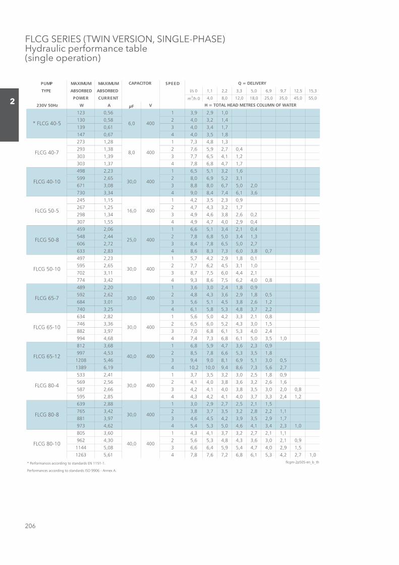
FLCG SERIES (TWIN VERSION, SINGLE-PHASE)Hydraulic performance table(single operation)
DEEPSMUMIXAMMUMIXAMPMUP
TYPE ABSORBED ABSORBED l/s 0 1,1 2,2 3,3 5,0 6,9 9,7 12,5 15,3
TNERRUCREWOP m3/h 0 4,0 8,0 12,0 18,0 25,0 35,0 45,0 55,0
230V 50Hz W A μF V
0,19,29,3165,0321
4,12,30,4285,0031
7,14,30,4316,0931
8,15,30,4476,0741
3,18,43,7182,1372
4,07,29,56,7283,1392
2,11,45,67,7393,1303
7,17,48,68,7473,1303
6,12,31,55,6132,2894
1,32,59,60,8256,2995
0,20,57,60,88,8380,3176
6,31,64,74,80,9443,3037
9,03,25,32,4151,1542
7,12,33,47,4252,1762
2,06,28,36,49,4343,1892
4,09,20,47,49,4455,1703
4,01,24,31,56,6160,2954
3,14,30,58,68,7244,2845
7,20,55,68,74,8327,2606
7,08,30,63,73,86,8438,2336
1,08,19,22,47,5132,2794
0,11,35,42,67,7256,2595
1,24,40,65,77,8311,3207
8,00,42,65,76,83,9424,3477
9,08,14,20,36,3102,2984
5,08,19,26,33,48,4226,2295
2,16,28,35,41,56,5310,3486
2,27,38,43,58,51,6452,3047
8,01,23,32,40,56,5128,2436
5,10,33,42,50,65,6263,3647
4,20,43,51,68,60,7379,3288
0,15,30,51,68,63,74,7486,4499
9,03,26,37,49,58,6186,3218
8,15,33,56,68,75,8235,4799
5,00,31,59,61,80,94,9364,58021
7,26,53,76,84,90,012,01491,69831
9,08,15,20,32,35,37,3114,2335
6,16,22,36,38,30,41,4265,2965
8,00,20,35,38,30,41,42,4366,2785
2,14,23,37,30,41,42,43,4458,2595
5,11,25,27,29,20,3188,2936
1,12,28,22,35,37,38,3224,3567
7,19,25,39,32,45,46,4379,3188
0,13,24,31,46,40,53,54,5426,4379
1,11,27,22,37,31,43,4106,3508
9,01,20,36,33,48,43,56,5203,4269
5,19,20,47,44,59,54,66,6380,54411
0,17,22,43,51,68,62,76,78,7416,53621
* Performances according to standards EN 1151-1. flcgm-2p50S-en_b_th
Performances according to standards ISO 9906 - Annex A.
400
40,0 400
30,0 400
400
40,0 400
30,0 400FLCG 80-4
FLCG 80-8
FLCG 80-10
6,0
8,0
25,0
30,0
30,0
FLCG 50-10
FLCG 65-7
* FLCG 40-5 400
FLCG 65-10
FLCG 65-12
FLCG 40-7
FLCG 40-10
FLCG 50-5
FLCG 50-8
400
30,0
16,0 400
400
30,0 400
H = TOTAL HEAD METRES COLUMN OF WATER
Q = DELIVERYCAPACITOR
400
Sezione_02_uk.indd 206Sezione_02_uk.indd 206 07/03/12 16.1307/03/12 16.13
207
2
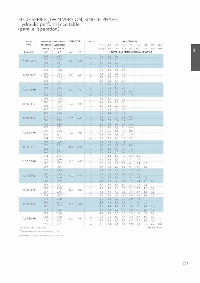
FLCG SERIES (TWIN VERSION, SINGLE-PHASE)Hydraulic performance table(parallel operation)
DEEPSMUMIXAMMUMIXAMPMUP
TYPE ABSORBED ABSORBED l/s 0 2,8 4,2 5,6 9,7 13,9 18,8 22,2 27,8
TNERRUCREWOP m3/h 0 10,0 15,0 20,0 35,0 50,0 67,5 80,0 100,0
230V 50Hz W* A* μF V
0,13,29,3165,0321
4,17,20,4285,0031
6,19,20,4316,0931
1,07,10,30,4476,0741
2,01,13,33,7182,1372
9,05,29,46,7283,1392
9,19,38,57,7393,1303
4,25,42,68,7473,1303
4,16,20,45,6132,2894
9,25,40,60,8256,2995
3,08,42,64,78,8380,3176
9,19,50,79,70,9443,3037
2,12,21,32,4151,1542
1,21,39,37,4252,1762
0,38,33,49,4343,1892
3,30,45,49,4455,1703
4,23,34,46,6160,2954
9,08,39,41,68,7244,2845
2,24,54,63,74,8327,2606
3,34,62,70,86,8438,2336
5,01,28,26,37,5132,2794
5,04,34,45,57,7256,2595
5,17,48,59,67,8311,3207
2,35,63,72,83,9424,3477
5,10,26,26,3102,2984
5,05,21,38,38,4226,2295
2,13,30,46,46,5310,3486
2,24,40,54,51,6452,3047
8,02,27,33,48,46,5128,2436
5,11,37,43,58,55,6263,3647
5,04,21,47,52,66,60,7379,3288
3,15,31,55,69,62,74,7486,4499
7,03,21,48,46,58,6186,3218
6,15,39,57,65,75,8235,4799
6,08,21,54,71,87,84,9364,58021
9,08,24,53,70,95,99,92,01491,69831
6,05,13,20,32,34,37,3114,2335
4,03,13,21,37,38,39,31,4265,2965
8,06,17,24,38,30,41,42,4366,2785
2,11,20,36,30,41,42,43,4458,2595
2,10,25,27,28,20,3188,2936
9,00,27,23,35,36,38,3224,3567
7,04,16,24,30,42,44,46,4379,3188
0,10,21,39,37,40,52,54,5426,4379
6,08,08,15,23,36,39,33,4106,3508
9,07,17,24,34,48,41,56,5203,4269
2,15,15,27,35,45,59,52,66,6380,54411
8,07,28,30,59,58,61,74,78,7416,53621
* Electric data refer to single motor. flcgm-2p50P-en_b_th
** Performances according to standards EN 1151-1.
Performances according to standards ISO 9906 - Annex A.
H = TOTAL HEAD METRES COLUMN OF WATER
Q = DELIVERYCAPACITOR
400
16,0 400
400
30,0 400
** FLCG 40-5 400
FLCG 65-10
FLCG 65-12
FLCG 40-7
FLCG 40-10
FLCG 50-5
FLCG 50-8
400
30,0
FLCG 80-4
FLCG 80-8
FLCG 80-10
6,0
8,0
25,0
30,0
30,0
FLCG 50-10
FLCG 65-7
400
40,0 400
30,0 400
400
40,0 400
30,0 400
Sezione_02_uk.indd 207Sezione_02_uk.indd 207 07/03/12 16.1307/03/12 16.13
208
2
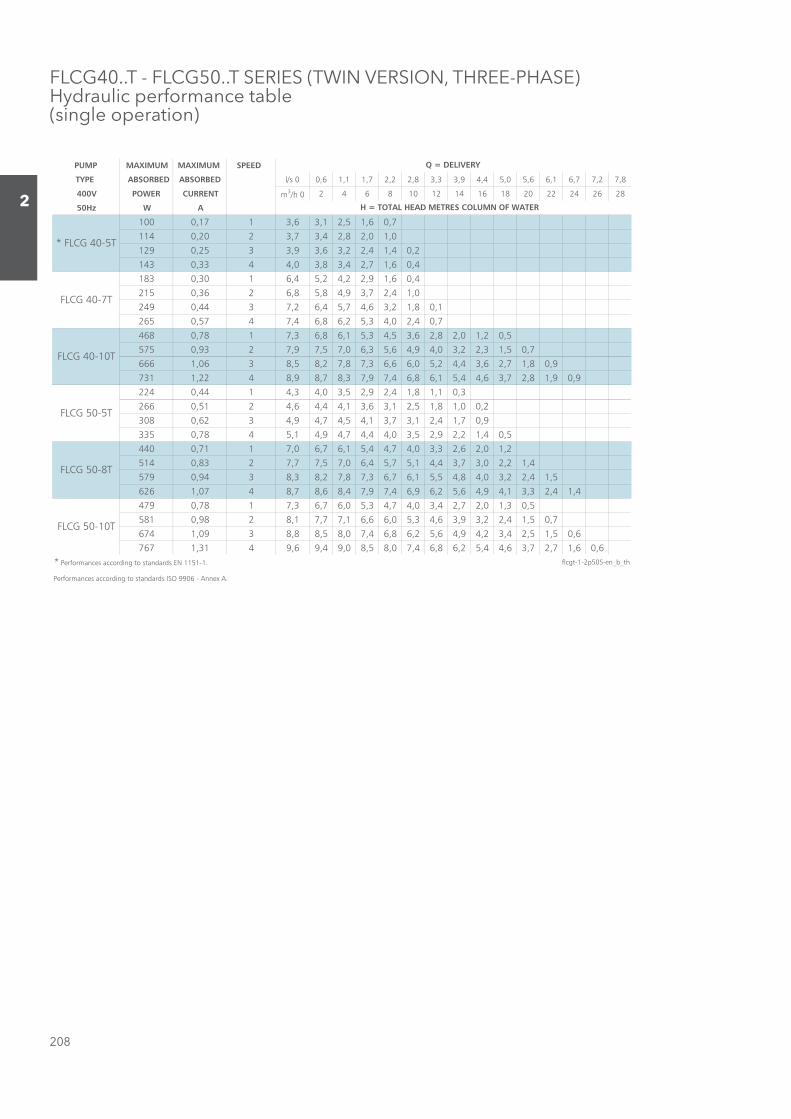
FLCG40..T - FLCG50..T SERIES (TWIN VERSION, THREE-PHASE)Hydraulic performance table(single operation)
PUMP MAXIMUM MAXIMUM SPEED
TYPE ABSORBED ABSORBED l/s 0 0,6 1,1 1,7 2,2 2,8 3,3 3,9 4,4 5,0 5,6 6,1 6,7 7,2 7,8
400V POWER CURRENT m3/h 0 2 4 6 8 10 12 14 16 18 20 22 24 26 28
50Hz W A
100 0,17 1 3,6 3,1 2,5 1,6 0,7
114 0,20 2 3,7 3,4 2,8 2,0 1,0
129 0,25 3 3,9 3,6 3,2 2,4 1,4 0,2
143 0,33 4 4,0 3,8 3,4 2,7 1,6 0,4
183 0,30 1 6,4 5,2 4,2 2,9 1,6 0,4
215 0,36 2 6,8 5,8 4,9 3,7 2,4 1,0
249 0,44 3 7,2 6,4 5,7 4,6 3,2 1,8 0,1
265 0,57 4 7,4 6,8 6,2 5,3 4,0 2,4 0,7
468 0,78 1 7,3 6,8 6,1 5,3 4,5 3,6 2,8 2,0 1,2 0,5
575 0,93 2 7,9 7,5 7,0 6,3 5,6 4,9 4,0 3,2 2,3 1,5 0,7
666 1,06 3 8,5 8,2 7,8 7,3 6,6 6,0 5,2 4,4 3,6 2,7 1,8 0,9
731 1,22 4 8,9 8,7 8,3 7,9 7,4 6,8 6,1 5,4 4,6 3,7 2,8 1,9 0,9
224 0,44 1 4,3 4,0 3,5 2,9 2,4 1,8 1,1 0,3
266 0,51 2 4,6 4,4 4,1 3,6 3,1 2,5 1,8 1,0 0,2
308 0,62 3 4,9 4,7 4,5 4,1 3,7 3,1 2,4 1,7 0,9
335 0,78 4 5,1 4,9 4,7 4,4 4,0 3,5 2,9 2,2 1,4 0,5
440 0,71 1 7,0 6,7 6,1 5,4 4,7 4,0 3,3 2,6 2,0 1,2
514 0,83 2 7,7 7,5 7,0 6,4 5,7 5,1 4,4 3,7 3,0 2,2 1,4
579 0,94 3 8,3 8,2 7,8 7,3 6,7 6,1 5,5 4,8 4,0 3,2 2,4 1,5
626 1,07 4 8,7 8,6 8,4 7,9 7,4 6,9 6,2 5,6 4,9 4,1 3,3 2,4 1,4
479 0,78 1 7,3 6,7 6,0 5,3 4,7 4,0 3,4 2,7 2,0 1,3 0,5
581 0,98 2 8,1 7,7 7,1 6,6 6,0 5,3 4,6 3,9 3,2 2,4 1,5 0,7
674 1,09 3 8,8 8,5 8,0 7,4 6,8 6,2 5,6 4,9 4,2 3,4 2,5 1,5 0,6
767 1,31 4 9,6 9,4 9,0 8,5 8,0 7,4 6,8 6,2 5,4 4,6 3,7 2,7 1,6 0,6* Performances according to standards EN 1151-1. flcgt-1-2p50S-en_b_th
Performances according to standards ISO 9906 - Annex A.
Q = DELIVERY
H = TOTAL HEAD METRES COLUMN OF WATER
FLCG 40-10T
FLCG 50-5T
FLCG 50-8T
FLCG 50-10T
* FLCG 40-5T
FLCG 40-7T
Sezione_02_uk.indd 208Sezione_02_uk.indd 208 07/03/12 16.1307/03/12 16.13

209
2
FLCG65..T - FLCG80..T SERIES (TWIN VERSION, THREE-PHASE)Hydraulic performance table(single operation)
PUMP MAXIMUM MAXIMUM SPEED
TYPE ABSORBED ABSORBED l/s 0 1,4 2,8 4,2 5,6 6,9 8,3 9,7 11,1 12,5 13,9 15,3 16,7 19,4 22,2
400V POWER CURRENT m3/h 0 5 10 15 20 25 30 35 40 45 50 55 60 70 80
50Hz W A
475 0,77 1 4,7 4,0 3,1 2,2 1,4
578 0,93 2 5,3 4,6 3,7 2,8 1,9
668 1,08 3 5,9 5,4 4,6 3,7 2,7 1,7 0,5
807 1,39 4 6,3 5,9 5,0 4,1 3,1 2,0 0,8
673 1,08 1 6,3 5,8 4,6 3,6 2,6 1,6 0,5
803 1,29 2 7,2 6,7 5,8 4,7 3,6 2,4 1,2
930 1,52 3 7,8 7,4 6,6 5,5 4,4 3,2 2,0 0,7
1079 2,02 4 8,5 8,3 7,4 6,4 5,3 4,1 2,8 1,4
863 1,42 1 7,9 7,1 6,0 4,9 3,9 2,8 1,6 0,5
1044 1,68 2 8,8 8,1 7,2 6,2 5,1 4,0 2,8 1,5
1205 1,95 3 9,4 8,9 8,1 7,1 6,1 5,0 3,8 2,4 1,0
1353 2,30 4 10,1 9,7 9,0 8,1 7,2 6,1 4,9 3,5 2,1
1511 2,40 1 11,6 11,0 9,8 8,6 7,3 6,0 4,7 3,1 1,4
1760 2,80 2 12,7 12,3 11,3 10,1 8,9 7,6 6,3 4,7 2,9 1,1
2002 3,16 3 13,5 13,4 12,5 11,4 10,2 9,0 7,7 6,2 4,5 2,5
2152 3,60 4 14,4 14,3 13,6 12,6 11,5 10,3 9,0 7,6 5,9 3,9 1,8
396 0,74 1 3,7 3,5 3,2 2,9 2,6 2,1 1,7 1,2 0,6
439 0,86 2 4,0 3,8 3,6 3,3 3,0 2,6 2,1 1,6 1,0
497 1,04 3 4,2 4,0 3,8 3,6 3,3 2,9 2,4 1,9 1,3
530 1,32 4 4,3 4,2 4,1 3,9 3,6 3,2 2,7 2,2 1,6 0,9
649 1,05 1 4,2 3,9 3,5 3,0 2,6 2,2 1,7 1,1 0,6
774 1,26 2 5,0 4,7 4,2 3,8 3,3 2,8 2,3 1,7 1,1
888 1,48 3 5,7 5,4 4,9 4,3 3,8 3,4 2,8 2,3 1,6 0,9
1043 1,98 4 6,4 6,2 5,7 5,1 4,6 4,0 3,5 2,9 2,3 1,5
839 1,34 1 5,7 5,2 4,8 4,4 4,0 3,5 3,0 2,4 1,8 1,2
987 1,58 2 6,7 6,2 5,7 5,3 4,9 4,4 3,8 3,2 2,6 1,9 1,2
1109 1,79 3 7,4 6,9 6,5 6,1 5,6 5,1 4,6 3,9 3,3 2,6 1,8
1259 2,12 4 8,4 7,8 7,4 7,0 6,5 6,0 5,4 4,8 4,1 3,3 2,5 1,6
1380 2,15 1 8,6 8,4 7,9 7,2 6,6 6,0 5,4 4,8 4,2 3,3 2,5 1,6
1553 2,46 2 9,9 9,5 9,0 8,4 7,8 7,2 6,6 5,9 5,2 4,4 3,5 2,6 1,8
1739 2,77 3 10,8 10,3 9,8 9,3 8,8 8,2 7,5 6,8 6,1 5,3 4,4 3,5 2,6
1931 3,24 4 11,6 11,2 10,7 10,3 9,8 9,2 8,5 7,8 7,0 6,2 5,3 4,3 3,3
1780 2,84 1 10,2 9,5 9,0 8,4 7,8 7,2 6,5 5,8 5,0 4,3 3,5 2,7 1,8
2117 3,36 2 11,5 11,0 10,5 10,0 9,4 8,8 8,2 7,5 6,7 5,9 5,1 4,2 3,3
2463 3,89 3 12,7 12,2 11,8 11,3 10,8 10,3 9,7 9,0 8,3 7,5 6,7 5,8 4,8 2,8
2735 4,92 4 13,9 13,5 13,1 12,7 12,2 11,7 11,2 10,6 10,0 9,2 8,4 7,5 6,6 4,4 2,1
Performances according to standards ISO 9906 - Annex A. flcgt-2-2p50S-en_b_th
Q = DELIVERY
H = TOTAL HEAD METRES COLUMN OF WATER
FLCG 80-4T
FLCG 80-8T
FLCG 80-15T
FLCG 65-7T
FLCG 65-10T
FLCG 65-12T
FLCG 65-16T
FLCG 80-12T
FLCG 80-10T
Sezione_02_uk.indd 209Sezione_02_uk.indd 209 07/03/12 16.1307/03/12 16.13

210
2
FLCG40..T - FLCG50..T SERIES (TWIN VERSION, THREE-PHASE)Hydraulic performance table(parallel operation)
PUMP MAXIMUM MAXIMUM SPEED
TYPE ABSORBED ABSORBED l/s 0 0,6 1,1 1,7 2,2 2,8 3,9 5,0 6,1 7,2 8,3 9,4 10,6 11,7 12,8
400V POWER CURRENT m3/h 0 2 4 6 8 10 14 18 22 26 30 34 38 42 46
50Hz W* A*100 0,17 1 3,6 3,3 3,1 2,7 2,3 1,8 0,8
114 0,20 2 3,7 3,6 3,4 3,1 2,7 2,2 1,2
129 0,25 3 3,9 3,8 3,6 3,4 3,0 2,6 1,5 0,3
143 0,33 4 4,0 3,9 3,8 3,6 3,3 2,9 1,8 0,5
183 0,30 1 6,4 5,7 5,1 4,6 4,0 3,3 1,8 0,5
215 0,36 2 6,8 6,2 5,8 5,3 4,7 4,1 2,6 1,1
249 0,44 3 7,2 6,7 6,3 6,0 5,5 4,9 3,4 1,8 0,1
265 0,57 4 7,4 7,0 6,8 6,5 6,1 5,6 4,2 2,5 0,7
468 0,78 1 7,3 7,0 6,6 6,2 5,7 5,2 4,1 3,1 2,1 1,1 0,2
575 0,93 2 7,9 7,7 7,4 7,0 6,7 6,3 5,3 4,3 3,3 2,2 1,2
666 1,06 3 8,5 8,3 8,1 7,8 7,5 7,2 6,4 5,5 4,5 3,4 2,3 1,2 0,2
731 1,22 4 8,9 8,8 8,6 8,4 8,1 7,8 7,2 6,4 5,5 4,5 3,4 2,2 1,0
224 0,44 1 4,3 4,2 4,0 3,7 3,4 3,1 2,5 1,8 1,1 0,3
266 0,51 2 4,6 4,5 4,4 4,2 4,0 3,8 3,2 2,6 1,8 1,0 0,1
308 0,62 3 4,9 4,8 4,7 4,6 4,4 4,3 3,8 3,2 2,5 1,7 0,8
335 0,78 4 5,1 5,0 4,9 4,8 4,7 4,5 4,1 3,6 2,9 2,1 1,3 0,3
440 0,71 1 7,0 6,9 6,6 6,4 6,0 5,7 5,0 4,3 3,6 2,9 2,2 1,5 0,7
514 0,83 2 7,7 7,6 7,4 7,2 7,0 6,7 6,0 5,3 4,6 3,9 3,2 2,4 1,6 0,8
579 0,94 3 8,3 8,3 8,2 8,0 7,8 7,5 7,0 6,4 5,7 5,0 4,2 3,5 2,6 1,7 0,8
626 1,07 4 8,7 8,7 8,6 8,5 8,3 8,1 7,7 7,1 6,5 5,8 5,1 4,3 3,5 2,6 1,6
479 0,78 1 7,3 7,0 6,6 6,2 5,9 5,5 4,7 4,0 3,3 2,5 1,7 0,9
581 0,98 2 8,1 7,9 7,6 7,3 7,0 6,7 6,0 5,3 4,5 3,7 2,8 1,9 0,9
674 1,09 3 8,8 8,7 8,5 8,2 7,9 7,6 6,9 6,2 5,5 4,7 3,9 2,9 1,9 0,8
767 1,31 4 9,6 9,5 9,3 9,1 8,9 8,6 8,0 7,4 6,7 6,0 5,1 4,1 3,0 1,9 0,7
* Electric data refer to single motor. flcgt-1-2p50P-en_b_th
** Performances according to standards EN 1151-1.
Performances according to standards ISO 9906 - Annex A.
Q = DELIVERY
H = TOTAL HEAD METRES COLUMN OF WATER
FLCG 40-10T
FLCG 50-5T
FLCG 50-8T
FLCG 50-10T
** FLCG 40-5T
FLCG 40-7T
Sezione_02_uk.indd 210Sezione_02_uk.indd 210 07/03/12 16.1307/03/12 16.13
211
2
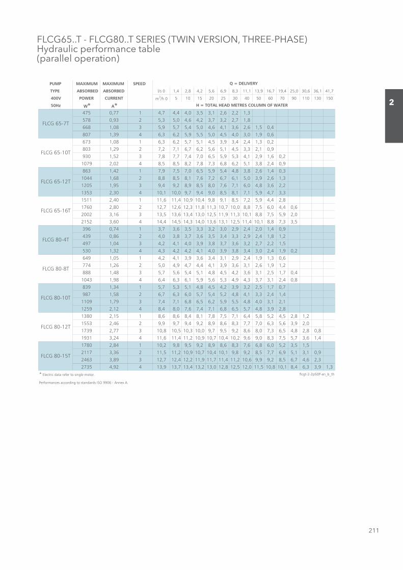
FLCG65..T - FLCG80..T SERIES (TWIN VERSION, THREE-PHASE)Hydraulic performance table(parallel operation)
PUMP MAXIMUM MAXIMUM SPEED
TYPE ABSORBED ABSORBED l/s 0 1,4 2,8 4,2 5,6 6,9 8,3 11,1 13,9 16,7 19,4 25,0 30,6 36,1 41,7
400V POWER CURRENT m3/h 0 5 10 15 20 25 30 40 50 60 70 90 110 130 150
50Hz W* A*475 0,77 1 4,7 4,4 4,0 3,5 3,1 2,6 2,2 1,3
578 0,93 2 5,3 5,0 4,6 4,2 3,7 3,2 2,7 1,8
668 1,08 3 5,9 5,7 5,4 5,0 4,6 4,1 3,6 2,6 1,5 0,4
807 1,39 4 6,3 6,2 5,9 5,5 5,0 4,5 4,0 3,0 1,9 0,6
673 1,08 1 6,3 6,2 5,7 5,1 4,5 3,9 3,4 2,4 1,3 0,2
803 1,29 2 7,2 7,1 6,7 6,2 5,6 5,1 4,5 3,3 2,1 0,9
930 1,52 3 7,8 7,7 7,4 7,0 6,5 5,9 5,3 4,1 2,9 1,6 0,2
1079 2,02 4 8,5 8,5 8,2 7,8 7,3 6,8 6,2 5,1 3,8 2,4 0,9
863 1,42 1 7,9 7,5 7,0 6,5 5,9 5,4 4,8 3,8 2,6 1,4 0,3
1044 1,68 2 8,8 8,5 8,1 7,6 7,2 6,7 6,1 5,0 3,9 2,6 1,3
1205 1,95 3 9,4 9,2 8,9 8,5 8,0 7,6 7,1 6,0 4,8 3,6 2,2
1353 2,30 4 10,1 10,0 9,7 9,4 9,0 8,5 8,1 7,1 5,9 4,7 3,3
1511 2,40 1 11,6 11,4 10,9 10,4 9,8 9,1 8,5 7,2 5,9 4,4 2,8
1760 2,80 2 12,7 12,6 12,3 11,8 11,3 10,7 10,0 8,8 7,5 6,0 4,4 0,6
2002 3,16 3 13,5 13,6 13,4 13,0 12,5 11,9 11,3 10,1 8,8 7,5 5,9 2,0
2152 3,60 4 14,4 14,5 14,3 14,0 13,6 13,1 12,5 11,4 10,1 8,8 7,3 3,5
396 0,74 1 3,7 3,6 3,5 3,3 3,2 3,0 2,9 2,4 2,0 1,4 0,9
439 0,86 2 4,0 3,8 3,7 3,6 3,5 3,4 3,3 2,9 2,4 1,8 1,2
497 1,04 3 4,2 4,1 4,0 3,9 3,8 3,7 3,6 3,2 2,7 2,2 1,5
530 1,32 4 4,3 4,2 4,2 4,1 4,0 3,9 3,8 3,4 3,0 2,4 1,9 0,2
649 1,05 1 4,2 4,1 3,9 3,6 3,4 3,1 2,9 2,4 1,9 1,3 0,6
774 1,26 2 5,0 4,9 4,7 4,4 4,1 3,9 3,6 3,1 2,6 1,9 1,2
888 1,48 3 5,7 5,6 5,4 5,1 4,8 4,5 4,2 3,6 3,1 2,5 1,7 0,4
1043 1,98 4 6,4 6,3 6,1 5,9 5,6 5,3 4,9 4,3 3,7 3,1 2,4 0,8
839 1,34 1 5,7 5,3 5,1 4,8 4,5 4,2 3,9 3,2 2,5 1,7 0,7
987 1,58 2 6,7 6,3 6,0 5,7 5,4 5,2 4,8 4,1 3,3 2,4 1,4
1109 1,79 3 7,4 7,1 6,8 6,5 6,2 5,9 5,5 4,8 4,0 3,1 2,1
1259 2,12 4 8,4 8,0 7,6 7,4 7,1 6,8 6,5 5,7 4,8 3,9 2,8
1380 2,15 1 8,6 8,6 8,4 8,1 7,8 7,5 7,1 6,4 5,8 5,2 4,5 2,8 1,2
1553 2,46 2 9,9 9,7 9,4 9,2 8,9 8,6 8,3 7,7 7,0 6,3 5,6 3,9 2,0
1739 2,77 3 10,8 10,5 10,3 10,0 9,7 9,5 9,2 8,6 8,0 7,3 6,5 4,8 2,8 0,8
1931 3,24 4 11,6 11,4 11,2 10,9 10,7 10,4 10,2 9,6 9,0 8,3 7,5 5,7 3,6 1,4
1780 2,84 1 10,2 9,8 9,5 9,2 8,9 8,6 8,3 7,6 6,8 6,0 5,2 3,5 1,5
2117 3,36 2 11,5 11,2 10,9 10,7 10,4 10,1 9,8 9,2 8,5 7,7 6,9 5,1 3,1 0,9
2463 3,89 3 12,7 12,4 12,2 11,9 11,7 11,4 11,2 10,6 9,9 9,2 8,5 6,7 4,6 2,3
2735 4,92 4 13,9 13,7 13,4 13,2 13,0 12,8 12,5 12,0 11,5 10,8 10,1 8,4 6,3 3,9 1,3
* Electric data refer to single motor. flcgt-2-2p50P-en_b_th
Performances according to standards ISO 9906 - Annex A.
FLCG 80-15T
FLCG 65-7T
FLCG 65-10T
FLCG 65-12T
FLCG 65-16T
FLCG 80-12T
FLCG 80-10T
Q = DELIVERY
H = TOTAL HEAD METRES COLUMN OF WATER
FLCG 80-4T
FLCG 80-8T
Sezione_02_uk.indd 211Sezione_02_uk.indd 211 07/03/12 16.1307/03/12 16.13
212
2
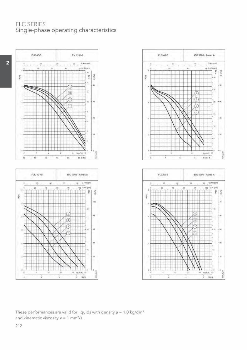
FLC SERIESSingle-phase operating characteristics
These performances are valid for liquids with density ρ = 1.0 kg/dm3 and kinematic viscosity ν = 1 mm2/s.
Sezione_02_uk.indd 212Sezione_02_uk.indd 212 07/03/12 16.1307/03/12 16.13
213
2
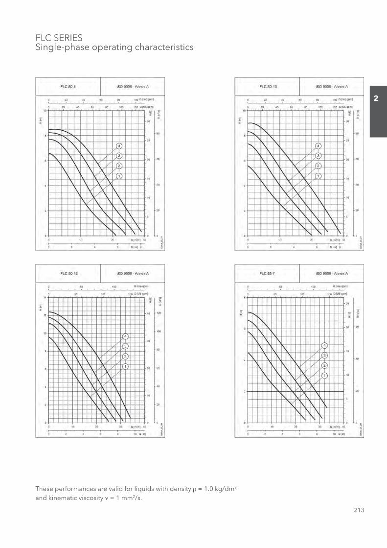
FLC SERIESSingle-phase operating characteristics
These performances are valid for liquids with density ρ = 1.0 kg/dm3 and kinematic viscosity ν = 1 mm2/s.
Sezione_02_uk.indd 213Sezione_02_uk.indd 213 07/03/12 16.1407/03/12 16.14
214
2
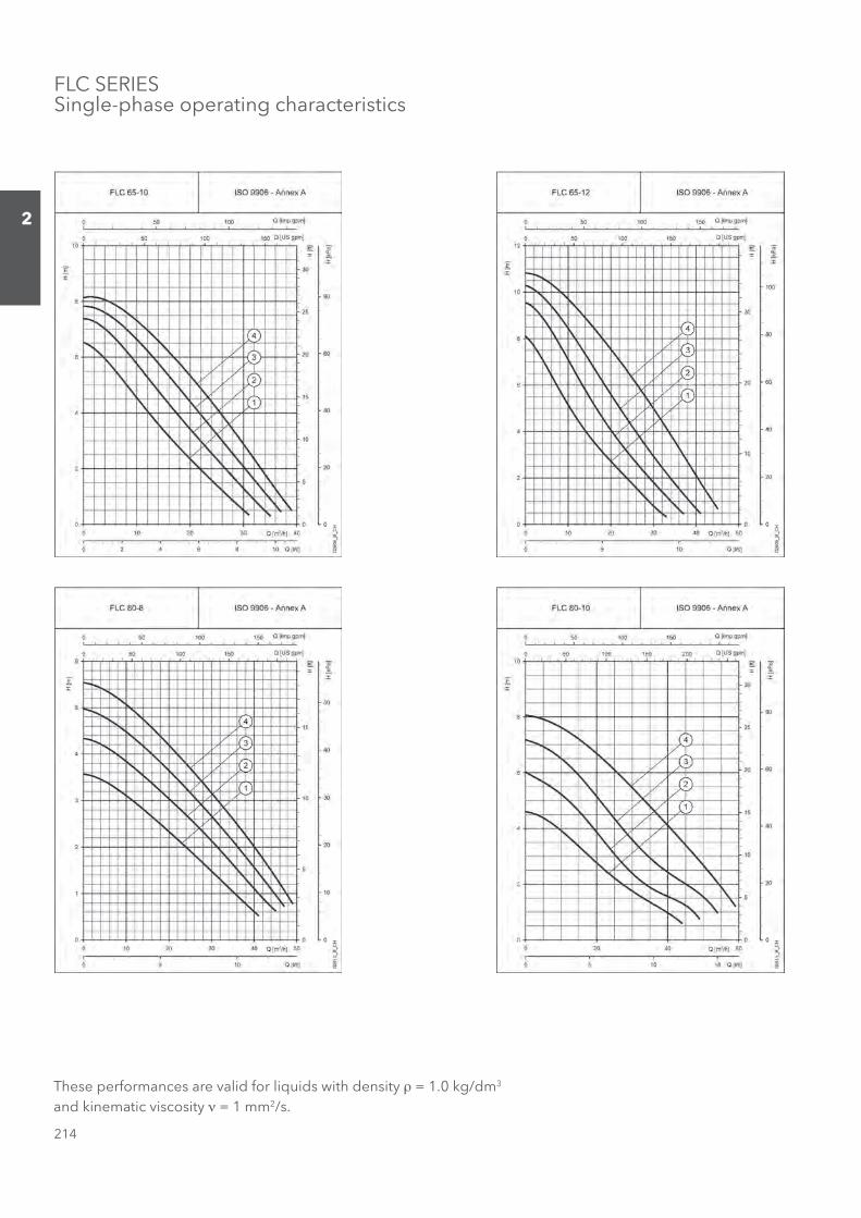
FLC SERIESSingle-phase operating characteristics
These performances are valid for liquids with density ρ = 1.0 kg/dm3 and kinematic viscosity ν = 1 mm2/s.
Sezione_02_uk.indd 214Sezione_02_uk.indd 214 07/03/12 16.1407/03/12 16.14
215
2
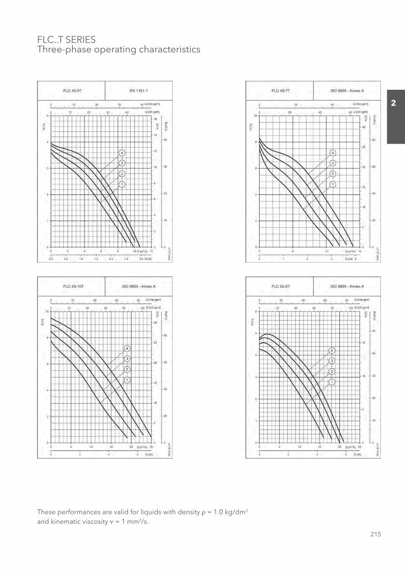
FLC..T SERIESThree-phase operating characteristics
These performances are valid for liquids with density ρ = 1.0 kg/dm3 and kinematic viscosity ν = 1 mm2/s.
Sezione_02_uk.indd 215Sezione_02_uk.indd 215 07/03/12 16.1407/03/12 16.14
216
2
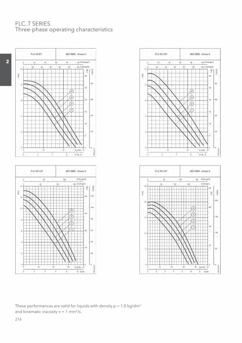
FLC..T SERIESThree-phase operating characteristics
These performances are valid for liquids with density ρ = 1.0 kg/dm3 and kinematic viscosity ν = 1 mm2/s.
Sezione_02_uk.indd 216Sezione_02_uk.indd 216 07/03/12 16.1407/03/12 16.14

217
2
FLC..T SERIESThree-phase operating characteristics
These performances are valid for liquids with density ρ = 1.0 kg/dm3 and kinematic viscosity ν = 1 mm2/s.
Sezione_02_uk.indd 217Sezione_02_uk.indd 217 07/03/12 16.1407/03/12 16.14
218
2
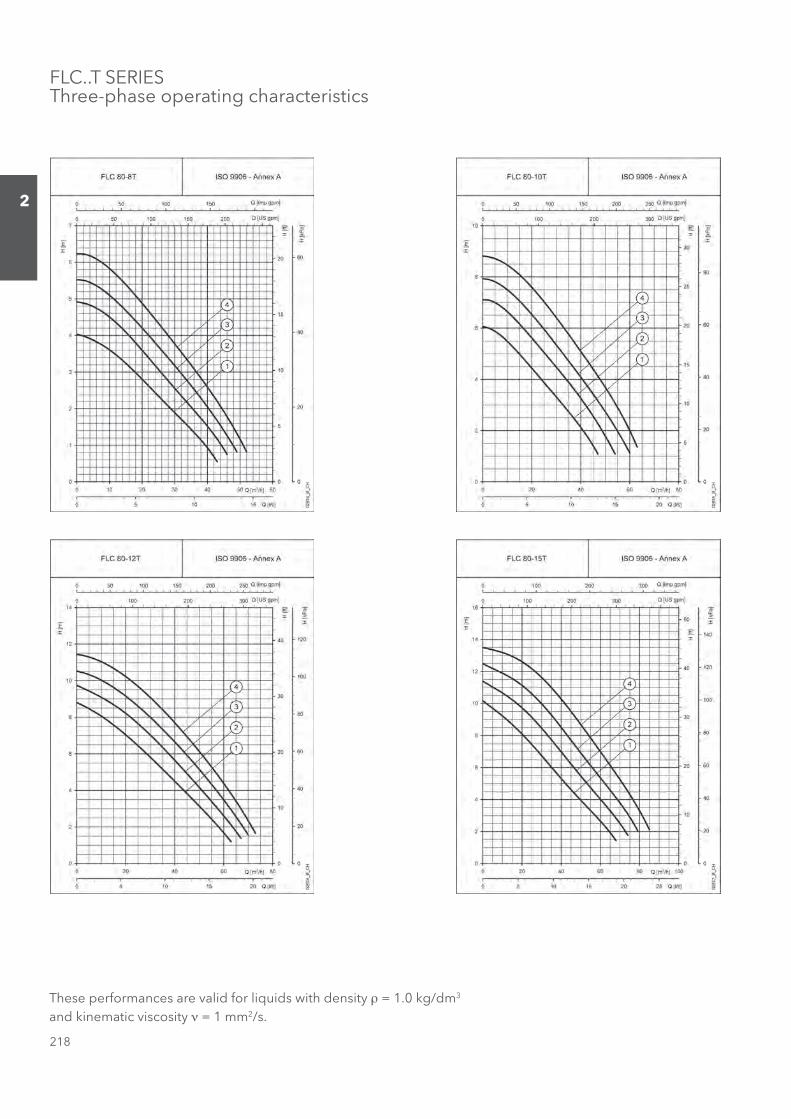
FLC..T SERIESThree-phase operating characteristics
These performances are valid for liquids with density ρ = 1.0 kg/dm3 and kinematic viscosity ν = 1 mm2/s.
Sezione_02_uk.indd 218Sezione_02_uk.indd 218 07/03/12 16.1407/03/12 16.14
219
2
FLCG SERIESSingle-phase operating characteristics
These performances are valid for liquids with density ρ = 1.0 kg/dm3 and kinematic viscosity ν = 1 mm2/s.
Sezione_02_uk.indd 219Sezione_02_uk.indd 219 07/03/12 16.1407/03/12 16.14

220
2
FLCG SERIESSingle-phase operating characteristics
These performances are valid for liquids with density ρ = 1.0 kg/dm3 and kinematic viscosity ν = 1 mm2/s.
Sezione_02_uk.indd 220Sezione_02_uk.indd 220 07/03/12 16.1407/03/12 16.14
221
2
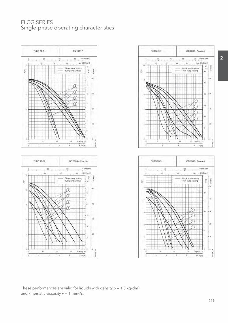
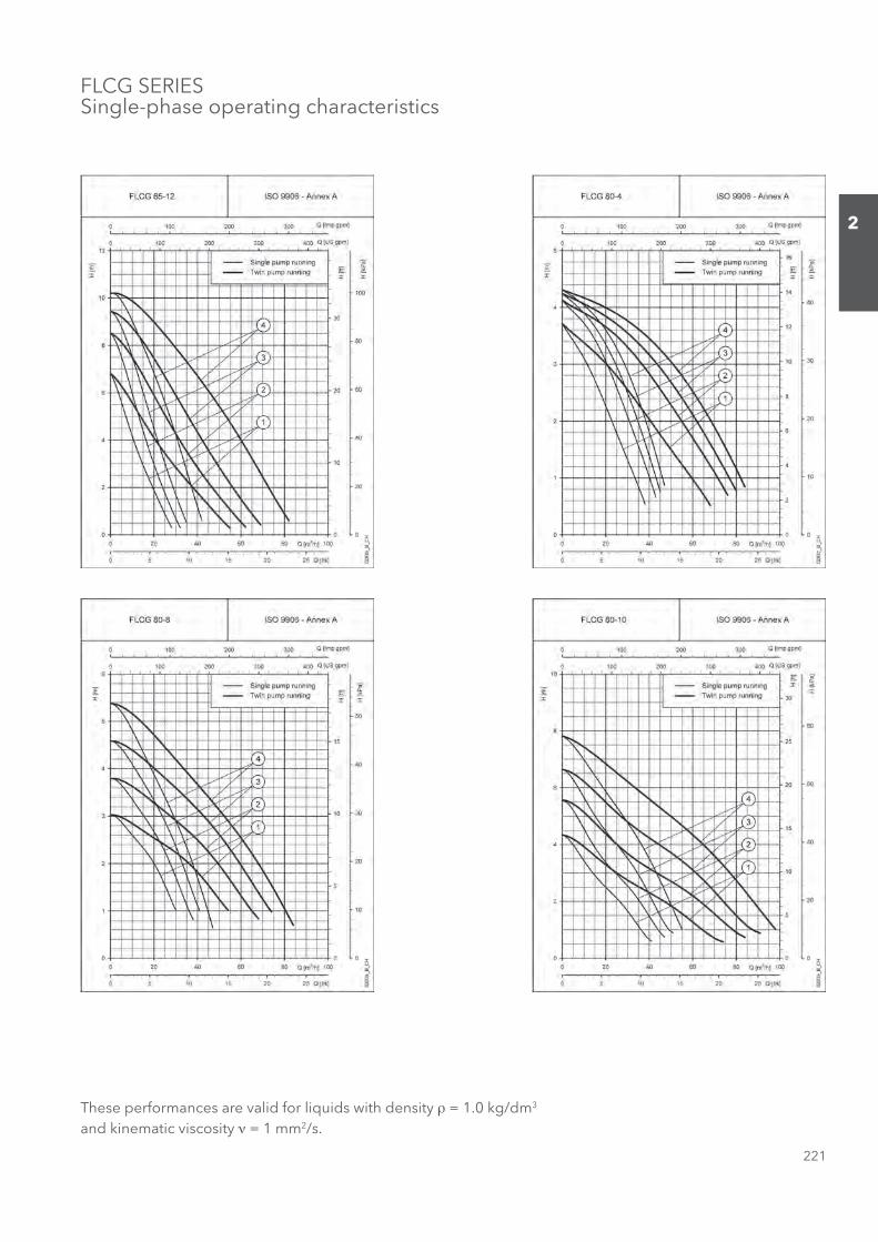
FLCG SERIESSingle-phase operating characteristics
These performances are valid for liquids with density ρ = 1.0 kg/dm3 and kinematic viscosity ν = 1 mm2/s.
Sezione_02_uk.indd 221Sezione_02_uk.indd 221 07/03/12 16.1407/03/12 16.14

222
2
FLCG..T SERIESThree-phase operating characteristics
These performances are valid for liquids with density ρ = 1.0 kg/dm3 and kinematic viscosity ν = 1 mm2/s.
Sezione_02_uk.indd 222Sezione_02_uk.indd 222 07/03/12 16.1407/03/12 16.14
223
2
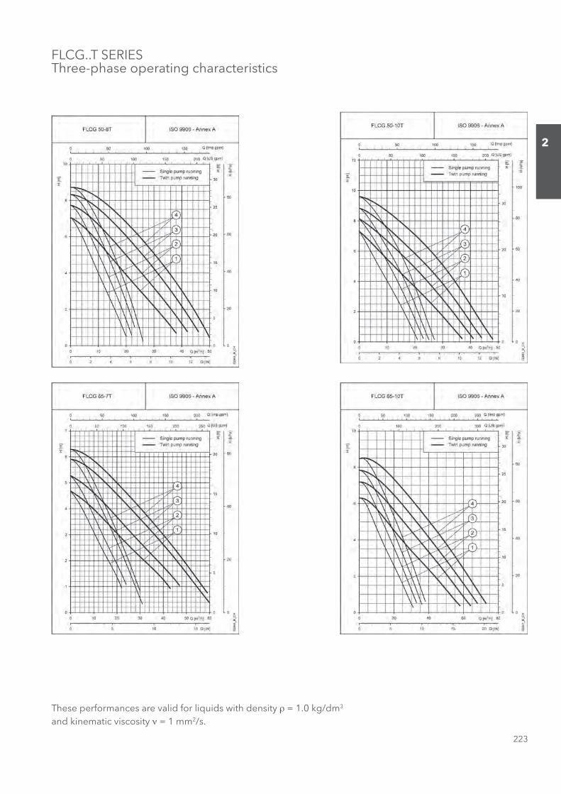
FLCG..T SERIESThree-phase operating characteristics
These performances are valid for liquids with density ρ = 1.0 kg/dm3 and kinematic viscosity ν = 1 mm2/s.
Sezione_02_uk.indd 223Sezione_02_uk.indd 223 07/03/12 16.1407/03/12 16.14
224
2
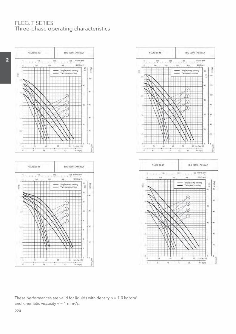
FLCG..T SERIESThree-phase operating characteristics
These performances are valid for liquids with density ρ = 1.0 kg/dm3 and kinematic viscosity ν = 1 mm2/s.
Sezione_02_uk.indd 224Sezione_02_uk.indd 224 07/03/12 16.1407/03/12 16.14
225
2
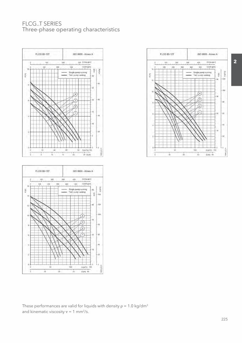
FLCG..T SERIESThree-phase operating characteristics
These performances are valid for liquids with density ρ = 1.0 kg/dm3 and kinematic viscosity ν = 1 mm2/s.
Sezione_02_uk.indd 225Sezione_02_uk.indd 225 07/03/12 16.1407/03/12 16.14
226
2
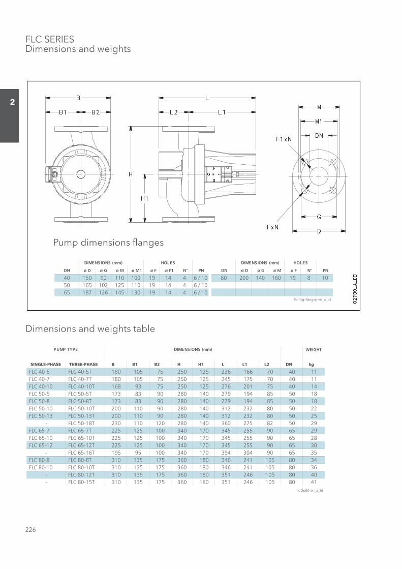
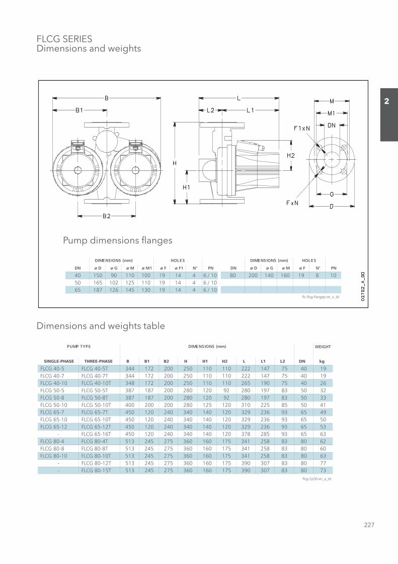
Pump dimensions fl anges
Dimensions and weights table
FLC SERIESDimensions and weights
WEIGHT
SINGLE-PHASE THREE-PHASE B B1 B2 H H1 L L1 L2 DN kg
FLC 40-5 FLC 40-5T 180 105 75 250 125 236 166 70 40 11 FLC 40-7 FLC 40-7T 180 105 75 250 125 245 175 70 40 11 FLC 40-10 FLC 40-10T 168 93 75 250 125 276 201 75 40 14 FLC 50-5 FLC 50-5T 173 83 90 280 140 279 194 85 50 18 FLC 50-8 FLC 50-8T 173 83 90 280 140 279 194 85 50 18 FLC 50-10 FLC 50-10T 200 110 90 280 140 312 232 80 50 22 FLC 50-13 FLC 50-13T 200 110 90 280 140 312 232 80 50 25
- FLC 50-18T 230 110 120 280 140 360 275 82 50 29 FLC 65-7 FLC 65-7T 225 125 100 340 170 345 255 90 65 29 FLC 65-10 FLC 65-10T 225 125 100 340 170 345 255 90 65 28 FLC 65-12 FLC 65-12T 225 125 100 340 170 345 255 90 65 30
- FLC 65-16T 195 95 100 340 170 394 304 90 65 35 FLC 80-8 FLC 80-8T 310 135 175 360 180 346 241 105 80 34 FLC 80-10 FLC 80-10T 310 135 175 360 180 346 241 105 80 36
- FLC 80-12T 310 135 175 360 180 351 246 105 80 40- FLC 80-15T 310 135 175 360 180 351 246 105 80 41
flc-2p50-en_a_td
)mm( SNOISNEMIDEPYT PMUP
DN ø D ø G ø M ø M1 ø F ø F1 N° PN DN ø D ø G ø M ø F N° PN
40 150 90 110 100 19 14 4 6 / 10 80 200 140 160 19 8 1050 165 102 125 110 19 14 4 6 / 1065 187 126 145 130 19 14 4 6 / 10
flc-flcg-flangep-en_a_td
SELOH)mm( SNOISNEMIDSELOH)mm( SNOISNEMID
Sezione_02_uk.indd 226Sezione_02_uk.indd 226 07/03/12 16.1407/03/12 16.14
227
2
FLCG SERIESDimensions and weights
Pump dimensions fl anges
Dimensions and weights table
DN ø D ø G ø M ø M1 ø F ø F1 N° PN DN ø D ø G ø M ø F N° PN
40 150 90 110 100 19 14 4 6 / 10 80 200 140 160 19 8 1050 165 102 125 110 19 14 4 6 / 1065 187 126 145 130 19 14 4 6 / 10
flc-flcg-flangep-en_a_td
SELOH)mm( SNOISNEMIDSELOH)mm( SNOISNEMID
WEIGHT
SINGLE-PHASE THREE-PHASE B B1 B2 H H1 H2 L L1 L2 DN kg
FLCG 40-5 FLCG 40-5T 344 172 200 250 110 110 222 147 75 40 19 FLCG 40-7 FLCG 40-7T 344 172 200 250 110 110 222 147 75 40 19 FLCG 40-10 FLCG 40-10T 348 172 200 250 110 110 265 190 75 40 26 FLCG 50-5 FLCG 50-5T 387 187 200 280 120 92 280 197 83 50 32 FLCG 50-8 FLCG 50-8T 387 187 200 280 120 92 280 197 83 50 33 FLCG 50-10 FLCG 50-10T 400 200 200 280 125 120 310 225 85 50 41 FLCG 65-7 FLCG 65-7T 450 120 240 340 140 120 329 236 93 65 49 FLCG 65-10 FLCG 65-10T 450 120 240 340 140 120 329 236 93 65 50 FLCG 65-12 FLCG 65-12T 450 120 240 340 140 120 329 236 93 65 53
- FLCG 65-16T 450 120 240 340 140 120 378 285 93 65 63 FLCG 80-4 FLCG 80-4T 513 245 275 360 160 175 341 258 83 80 62 FLCG 80-8 FLCG 80-8T 513 245 275 360 160 175 341 258 83 80 60 FLCG 80-10 FLCG 80-10T 513 245 275 360 160 175 341 258 83 80 63
- FLCG 80-12T 513 245 275 360 160 175 390 307 83 80 77- FLCG 80-15T 513 245 275 360 160 175 390 307 83 80 73
flcg-2p50-en_a_td
)mm( SNOISNEMIDEPYT PMUP
Sezione_02_uk.indd 227Sezione_02_uk.indd 227 07/03/12 16.1407/03/12 16.14

228
2
Sezione_02_uk.indd 228Sezione_02_uk.indd 228 07/03/12 16.1407/03/12 16.14
229
2
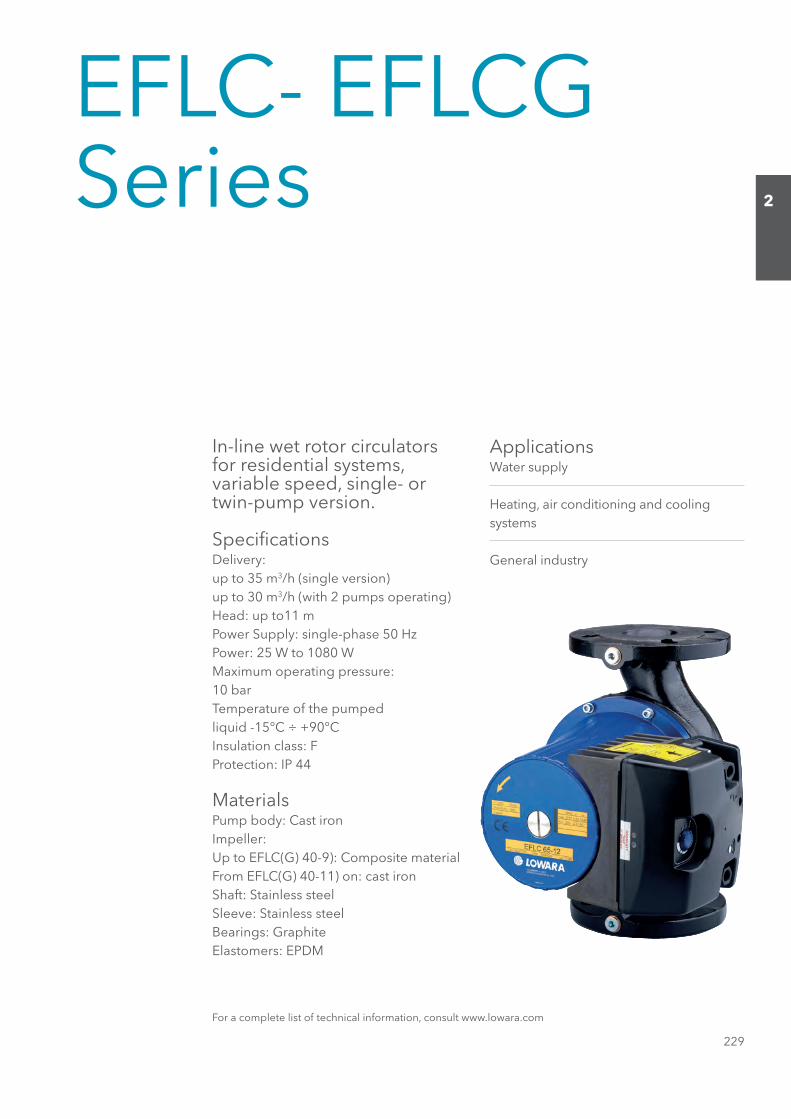
EFLC- EFLCGSeries
In-line wet rotor circulatorsfor residential systems, variable speed, single- or twin-pump version.
Specifi cationsDelivery:up to 35 m3/h (single version)up to 30 m3/h (with 2 pumps operating)Head: up to11 mPower Supply: single-phase 50 HzPower: 25 W to 1080 WMaximum operating pressure:10 barTemperature of the pumpedliquid -15°C ÷ +90°CInsulation class: FProtection: IP 44
MaterialsPump body: Cast ironImpeller:Up to EFLC(G) 40-9): Composite materialFrom EFLC(G) 40-11) on: cast ironShaft: Stainless steelSleeve: Stainless steelBearings: GraphiteElastomers: EPDM
ApplicationsWater supply
Heating, air conditioning and coolingsystems
General industry
For a complete list of technical information, consult www.lowara.com
Sezione_02_uk.indd 229Sezione_02_uk.indd 229 07/03/12 16.1407/03/12 16.14
230
2
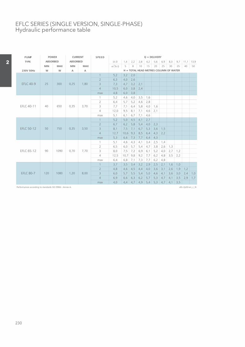
EFLC SERIES (SINGLE VERSION, SINGLE-PHASE)Hydraulic performance table
DEEPSPMUP
TYPE l/s 0 1,4 2,2 2,8 4,2 5,6 6,9 8,3 9,7 11,1 13,9
MIN MAX MIN MAX m3/h 0 5 8 10 15 20 25 30 35 40 50
230V 50Hz W W A A
1 5,2 3,2 2,0
2 6,3 4,0 2,6
3 7,3 4,7 3,2 2,1
4 10,5 6,0 3,8 2,4
max 4,8 6,0 3,8
1 5,2 4,6 4,0 3,5 1,6
2 6,4 5,7 5,2 4,6 2,8
3 7,7 7,1 6,4 5,8 4,0 1,6
4 12,0 9,5 8,1 7,1 4,6 2,1
max 5,1 6,1 6,7 7,1 4,6
1 5,2 5,0 4,5 4,1 2,7
2 6,7 6,2 5,8 5,4 4,0 2,3
3 8,1 7,5 7,1 6,7 5,3 3,6 1,5
4 12,7 10,6 9,3 8,5 6,4 4,3 2,2
max 5,3 6,6 7,3 7,7 6,4 4,3
1 5,1 4,6 4,3 4,1 3,4 2,5 1,4
2 6,5 6,0 5,7 5,4 4,7 3,8 2,6 1,3
3 8,0 7,5 7,2 6,9 6,1 5,2 4,0 2,7 1,2
4 12,5 10,7 9,8 9,2 7,7 6,2 4,8 3,5 2,2
max 6,4 6,8 7,1 7,3 7,7 6,2 4,8
1 3,7 3,5 3,4 3,2 2,9 2,5 2,1 1,6 1,0
2 4,8 4,6 4,5 4,4 4,0 3,6 3,1 2,6 1,9 1,2
3 6,0 5,7 5,5 5,4 5,0 4,6 4,1 3,6 3,0 2,4 1,0
4 6,9 6,6 6,3 6,2 5,7 5,3 4,7 4,1 3,5 2,9 1,7
max 4,0 4,4 4,7 4,9 5,4 5,3 4,7 4,1 3,5
Performances according to standards ISO 9906 - Annex A. eflc-2p50-en_c_th
Q = DELIVERY
H = TOTAL HEAD METRES COLUMN OF WATER
POWER
ABSORBED ABSORBED
CURRENT
300 0,25 1,80
EFLC 40-11 40 650 0,35 3,70
EFLC 40-9 25
3,50
EFLC 65-12 90 1090 0,70 7,70
EFLC 50-12 50 750 0,35
8,00EFLC 80-7 120 1080 1,20
Sezione_02_uk.indd 230Sezione_02_uk.indd 230 07/03/12 16.1407/03/12 16.14
231
2
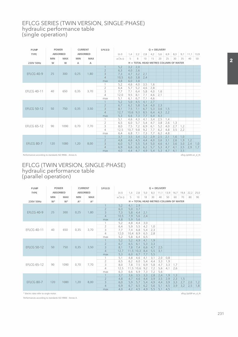
EFLCG SERIES (TWIN VERSION, SINGLE-PHASE)hydraulic performance table(single operation)
EFLCG (TWIN VERSION, SINGLE-PHASE)hydraulic performance table(parallel operation)
DEEPSPMUP
TYPE l/s 0 1,4 2,2 2,8 4,2 5,6 6,9 8,3 9,7 11,1 13,9
MIN MAX MIN MAX m3/h 0 5 8 10 15 20 25 30 35 40 50
230V 50Hz W W A A
1 5,2 3,2 2,02 6,3 4,0 2,63 7,3 4,7 3,2 2,14 10,5 6,0 3,8 2,4
max 4,8 6,0 3,81 5,2 4,6 4,0 3,5 1,62 6,4 5,7 5,2 4,6 2,83 7,7 7,1 6,4 5,8 4,0 1,64 12,0 9,5 8,1 7,1 4,6 2,1
max 5,1 6,1 6,7 7,1 4,61 5,2 5,0 4,5 4,1 2,72 6,7 6,2 5,8 5,4 4,0 2,33 8,1 7,5 7,1 6,7 5,3 3,6 1,54 12,7 10,6 9,3 8,5 6,4 4,3 2,2
max 5,3 6,6 7,3 7,7 6,4 4,31 5,1 4,6 4,3 4,1 3,4 2,5 1,42 6,5 6,0 5,7 5,4 4,7 3,8 2,6 1,33 8,0 7,5 7,2 6,9 6,1 5,2 4,0 2,7 1,24 12,5 10,7 9,8 9,2 7,7 6,2 4,8 3,5 2,2
max 6,4 6,8 7,1 7,3 7,7 6,2 4,81 3,7 3,5 3,4 3,2 2,9 2,5 2,1 1,6 1,02 4,8 4,6 4,5 4,4 4,0 3,6 3,1 2,6 1,9 1,23 6,0 5,7 5,5 5,4 5,0 4,6 4,1 3,6 3,0 2,4 1,04 6,9 6,6 6,3 6,2 5,7 5,3 4,7 4,1 3,5 2,9 1,7
max 4,0 4,4 4,7 4,9 5,4 5,3 4,7 4,1 3,5Performances according to standards ISO 9906 - Annex A. eflcg-2p50S-en_d_th
7,70
EFLCG 80-7 120 1080 1,20 8,00
EFLCG 65-12 90 1090 0,70
Q = DELIVERY
H = TOTAL HEAD METRES COLUMN OF WATER
POWER
ABSORBED ABSORBED
CURRENT
300 0,25 1,80
EFLCG 40-11 40 650 0,35 3,70
EFLCG 40-9 25
3,50EFLCG 50-12 50 750 0,35
DEEPSPMUP
TYPE l/s 0 1,4 2,8 5,0 8,3 11,1 13,9 16,7 19,4 22,2 25,0
MIN MAX MIN MAX m3/h 0 5 10 18 30 40 50 60 70 80 90
230V 50Hz W* W* A* A*
1 5,2 4,1 2,92 6,3 5,0 3,73 7,3 5,8 4,4 2,14 10,5 7,9 5,6 2,4
max 4,8 5,9 5,61 5,2 4,8 4,4 3,02 6,4 5,9 5,5 4,2 1,03 7,7 7,4 6,8 5,4 2,34 12,0 10,4 8,9 6,5 2,8
max 5,2 5,8 6,4 6,51 5,2 5,2 4,9 4,1 1,92 6,7 6,5 6,1 5,3 3,33 8,1 7,8 7,4 6,6 4,7 2,54 12,7 11,5 10,3 8,4 5,5 3,1
max 5,3 6,0 6,7 7,7 5,51 5,1 4,8 4,6 4,1 3,1 2,0 0,82 6,5 6,2 6,0 5,4 4,4 3,3 1,93 8,0 7,8 7,5 6,9 5,8 4,7 3,3 1,74 12,5 11,5 10,6 9,2 7,2 5,6 4,1 2,6
max 6,3 6,6 6,9 7,3 7,2 5,61 3,7 3,6 3,5 3,3 2,8 2,4 1,9 1,32 4,8 4,7 4,6 4,4 3,9 3,5 2,9 2,3 1,53 6,0 5,9 5,7 5,4 4,9 4,4 3,9 3,3 2,7 2,0 1,24 6,9 6,7 6,5 6,2 5,6 5,1 4,5 3,9 3,2 2,5 1,8
max 4,0 4,2 4,5 4,9 5,5 5,1 4,5* Electric data refer to single motor. eflcg-2p50P-en_d_th
Performances according to standards ISO 9906 - Annex A.
7,70
EFLCG 80-7 120 1080 1,20 8,00
EFLCG 65-12 90 1090 0,70
Q = DELIVERY
H = TOTAL HEAD METRES COLUMN OF WATER
POWER
ABSORBED ABSORBED
CURRENT
300 0,25 1,80
EFLCG 40-11 40 650 0,35 3,70
EFLCG 40-9 25
3,50EFLCG 50-12 50 750 0,35
Sezione_02_uk.indd 231Sezione_02_uk.indd 231 07/03/12 16.1407/03/12 16.14
232
2
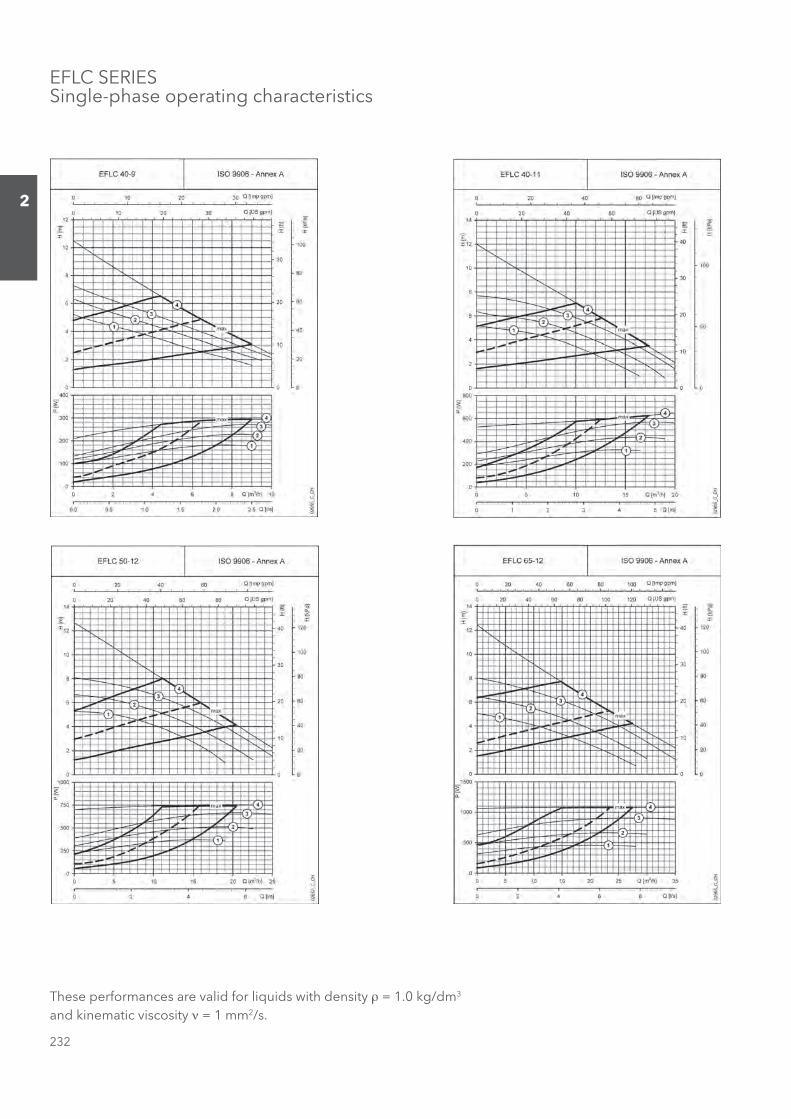
EFLC SERIESSingle-phase operating characteristics
These performances are valid for liquids with density ρ = 1.0 kg/dm3 and kinematic viscosity ν = 1 mm2/s.
Sezione_02_uk.indd 232Sezione_02_uk.indd 232 07/03/12 16.1407/03/12 16.14
233
2
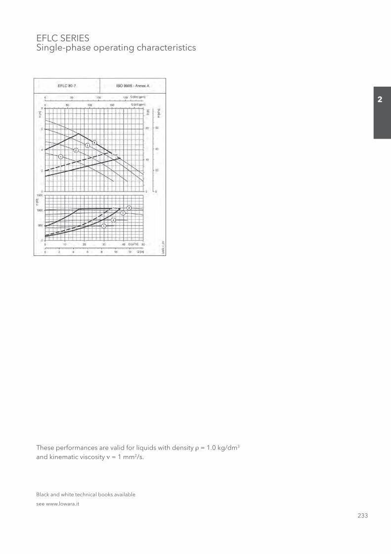
EFLC SERIESSingle-phase operating characteristics
These performances are valid for liquids with density ρ = 1.0 kg/dm3 and kinematic viscosity ν = 1 mm2/s.
Black and white technical books available
see www.lowara.it
Sezione_02_uk.indd 233Sezione_02_uk.indd 233 07/03/12 16.1407/03/12 16.14
234
2
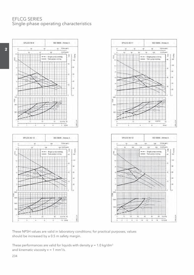
EFLCG SERIESSingle-phase operating characteristics
These NPSH values are valid in laboratory conditions; for practical purposes, values should be increased by a 0.5 m safety margin.
These performances are valid for liquids with density ρ = 1.0 kg/dm3 and kinematic viscosity ν = 1 mm2/s.
Sezione_02_uk.indd 234Sezione_02_uk.indd 234 07/03/12 16.1407/03/12 16.14
235
2
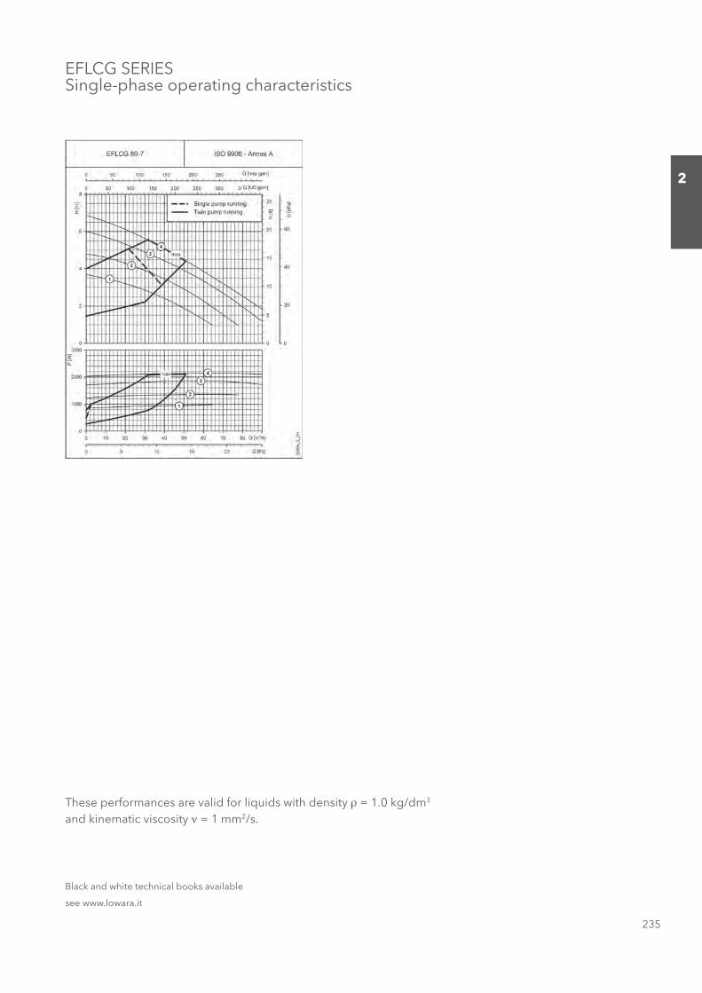
EFLCG SERIESSingle-phase operating characteristics
These performances are valid for liquids with density ρ = 1.0 kg/dm3 and kinematic viscosity ν = 1 mm2/s.
Black and white technical books available
see www.lowara.it
Sezione_02_uk.indd 235Sezione_02_uk.indd 235 07/03/12 16.1407/03/12 16.14
236
2
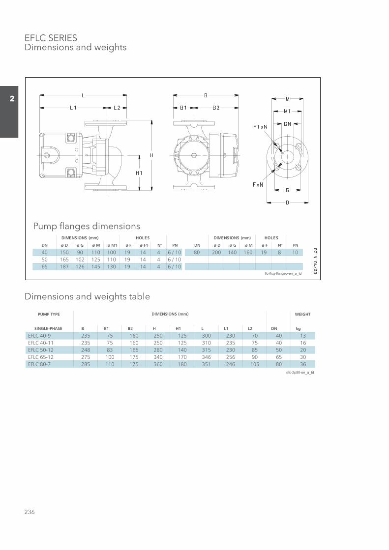
EFLC SERIESDimensions and weights
Dimensions and weights table
PUMP TYPE WEIGHT
SINGLE-PHASE B B1 B2 H H1 L L1 L2 DN kg
EFLC 40-9 235 75 160 250 125 300 230 70 40 13 EFLC 40-11 235 75 160 250 125 310 235 75 40 16 EFLC 50-12 248 83 165 280 140 315 230 85 50 20 EFLC 65-12 275 100 175 340 170 346 256 90 65 30 EFLC 80-7 285 110 175 360 180 351 246 105 80 36
efc-2p50-en_a_td
DIMENSIONS (mm)
DN ø D ø G ø M ø M1 ø F ø F1 N° PN DN ø D ø G ø M ø F N° PN
40 150 90 110 100 19 14 4 6 / 10 80 200 140 160 19 8 1050 165 102 125 110 19 14 4 6 / 1065 187 126 145 130 19 14 4 6 / 10
flc-flcg-flangep-en_a_td
SELOH)mm( SNOISNEMIDSELOH)mm( SNOISNEMID
Pump fl anges dimensions
Sezione_02_uk.indd 236Sezione_02_uk.indd 236 07/03/12 16.1407/03/12 16.14

237
2
DN ø D ø G ø M ø M1 ø F ø F1 N° PN DN ø D ø G ø M ø F N° PN
40 150 90 110 100 19 14 4 6 / 10 80 200 140 160 19 8 1050 165 102 125 110 19 14 4 6 / 1065 187 126 145 130 19 14 4 6 / 10
flc-flcg-flangep-en_a_td
SELOH)mm( SNOISNEMIDSELOH)mm( SNOISNEMID
EFLCG SERIESDimensions and weights
Dimensions and weights table
Pump fl anges dimensions
PUMP TYPE WEIGHT
B B1 B2 H H1 H2 L L1 L2 DN kg
EFLCG 40-9 436 218 200 250 105 170 287 212 75 40 22 EFLCG 40-11 520 265 200 250 105 165 304 229 75 40 29 EFLCG 50-12 490 245 200 280 120 170 317 198 83 50 35 EFLCG 65-12 528 300 275 340 140 180 328 235 93 65 54 EFLCG 80-7 660 340 275 360 100 180 342 240 102 80 70
eflcg-2p50-en_b_td
DIMENSIONS (mm)
Sezione_02_uk.indd 237Sezione_02_uk.indd 237 07/03/12 16.1407/03/12 16.14
238
2
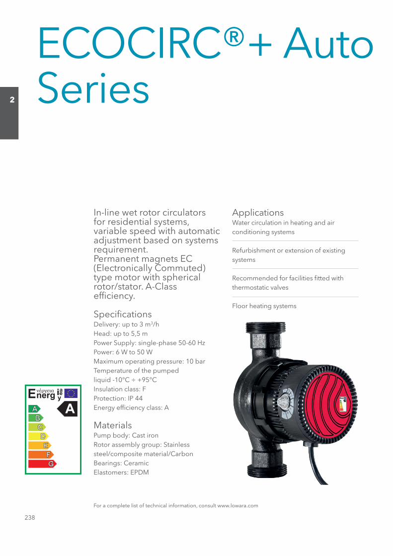
ECOCIRC®+ Auto Series
In-line wet rotor circulators for residential systems, variable speed with automatic adjustment based on systems requirement.Permanent magnets EC (Electronically Commuted) type motor with spherical rotor/stator. A-Class effi ciency.
Specifi cationsDelivery: up to 3 m3/hHead: up to 5,5 mPower Supply: single-phase 50-60 HzPower: 6 W to 50 WMaximum operating pressure: 10 barTemperature of the pumpedliquid -10°C ÷ +95°CInsulation class: FProtection: IP 44Energy effi ciency class: A
MaterialsPump body: Cast ironRotor assembly group: Stainlesssteel/composite material/CarbonBearings: CeramicElastomers: EPDM
ApplicationsWater circulation in heating and airconditioning systems
Refurbishment or extension of existingsystems
Recommended for facilities fi tted withthermostatic valves
Floor heating systems
For a complete list of technical information, consult www.lowara.com
Sezione_02_uk.indd 238Sezione_02_uk.indd 238 07/03/12 16.1407/03/12 16.14

239
2
EA+ SERIESSingle-phase operating characteristics
These NPSH values are valid in laboratory conditions; for practical purposes, values should be increased by a 0.5 m safety margin.
These performances are valid for liquids with density ρ = 1.0 kg/dm3 and kinematic viscosity ν = 1 mm2/s.
Sezione_02_uk.indd 239Sezione_02_uk.indd 239 07/03/12 16.1407/03/12 16.14
240
2
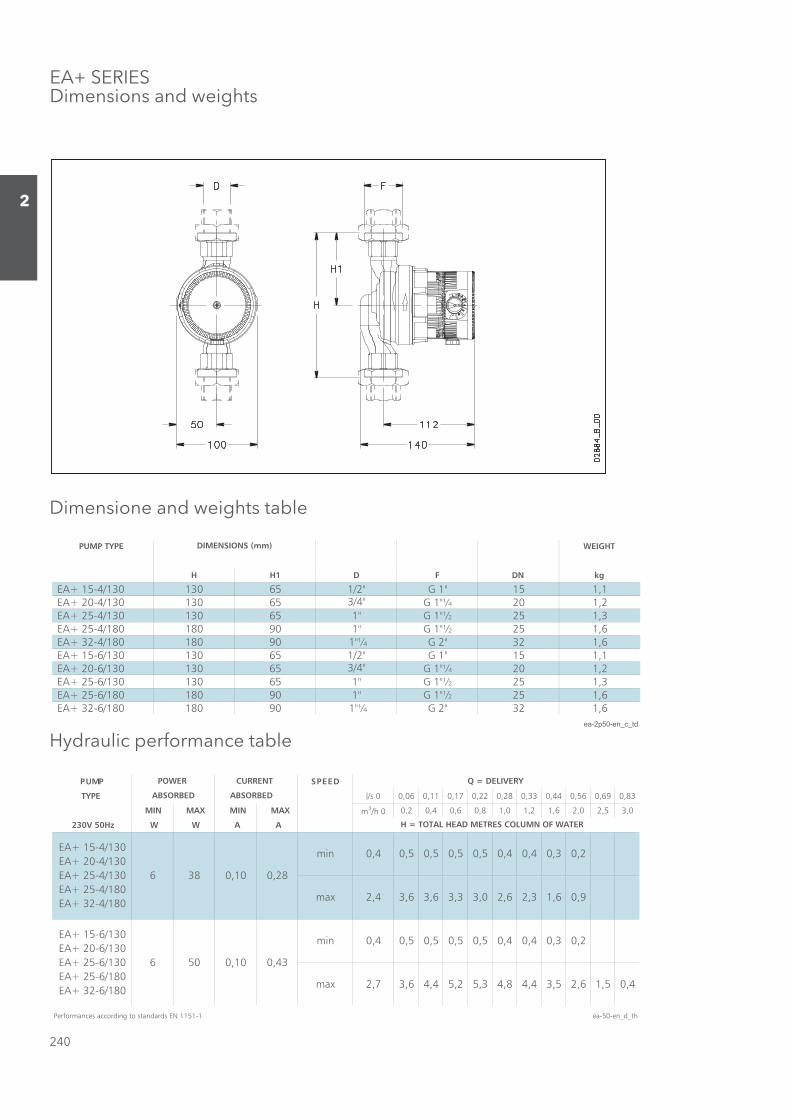
EA+ SERIESDimensions and weights
Dimensione and weights table
PUMP TYPE WEIGHT
H H1 D F DN kg
EA+ 15-4/130 130 65 1/2" G 1" 15 1,1 EA+ 20-4/130 130 65 3/4" G 1"¼ 20 1,2 EA+ 25-4/130 130 65 1" G 1"½ 25 1,3 EA+ 25-4/180 180 90 1" G 1"½ 25 1,6 EA+ 32-4/180 180 90 1"¼ G 2" 32 1,6 EA+ 15-6/130 130 65 1/2" G 1" 15 1,1 EA+ 20-6/130 130 65 3/4" G 1"¼ 20 1,2 EA+ 25-6/130 130 65 1" G 1"½ 25 1,3 EA+ 25-6/180 180 90 1" G 1"½ 25 1,6 EA+ 32-6/180 180 90 1"¼ G 2" 32 1,6
ea-2p50-en_c_td
DIMENSIONS (mm)
Hydraulic performance table
DEEPSPMUP
TYPE l/s 0 0,06 0,11 0,17 0,22 0,28 0,33 0,44 0,56 0,69 0,83
MIN MAX MIN MAX m3/h 0 0,2 0,4 0,6 0,8 1,0 1,2 1,6 2,0 2,5 3,0
230V 50Hz W W A A
Performances according to standards EN 1151-1 ea-50-en_d_th
max 2,7 3,6 4,4
0,5 0,5 0,5
0,45,2 5,3 4,8 4,4
max
min 0,4 0,5
2,4 3,6 3,6 3,3 3,0 2,6 2,3 1,6
EA+ 15-4/130 EA+ 20-4/130 EA+ 25-4/130 EA+ 25-4/180 EA+ 32-4/180
0,10 0,286 38
EA+ 15-6/130 EA+ 20-6/130 EA+ 25-6/130 EA+ 25-6/180 EA+ 32-6/180
6 50 0,10
Q = DELIVERY
H = TOTAL HEAD METRES COLUMN OF WATER
0,4 0,5 0,5 0,5 0,5 0,4 0,4 0,3
POWER
ABSORBED ABSORBED
CURRENT
0,43
0,2
0,4 0,3 0,2
2,6
0,9
0,4
3,5
min
1,5
Sezione_02_uk.indd 240Sezione_02_uk.indd 240 07/03/12 16.1407/03/12 16.14

241
2
ECOCIRC®+ Vario Series
In-line wet rotor circulators for residential systems, variable speed with automatic adjustment based on systems requirement. Permanent magnets EC (Electronically Commuted) type motor with spherical rotor/stator.
Specifi cationsDelivery: up to 3 m3/hHead: up to 5,5 mPower Supply: single-phase 50-60 HzPower: 96 W to 50 WMaximum operating pressure: 6 barTemperature of the pumpedliquid -10°C ÷ +95°CInsulation class: FProtection: IP 44Energy effi ciency class:A (4 m head)B (6 m head)
MaterialsPump body: Cast ironRotor assembly group: Stainlesssteel/composite material/CarbonBearings: CeramicElastomers: EPDM
ApplicationsWater circulation in heating and airconditioning systems
Refurbishment or extension of existingsystems
Solar panel heating systems
Single-family houses
Closed loops cooling circuit
For a complete list of technical information, consult www.lowara.com
Sezione_02_uk.indd 241Sezione_02_uk.indd 241 07/03/12 16.1407/03/12 16.14

242
2
SERIE EV+Single-phase operatimg characteristics
These NPSH values are valid in laboratory conditions; for practical purposes, values should be increased by a 0.5 m safety margin.
These performances are valid for liquids with density ρ = 1.0 kg/dm3 and kinematic viscosity ν = 1 mm2/s.
Sezione_02_uk.indd 242Sezione_02_uk.indd 242 07/03/12 16.1407/03/12 16.14

243
2
Dimensions and weights table
PUMP TYPE WEIGHT
H H1 D F DN kg
EV+ 15-4/130 130 65 1/2" G 1" 15 1,1 EV+ 20-4/130 130 65 3/4" G 1"¼ 20 1,2 EV+ 25-4/130 130 65 1" G 1"½ 25 1,3 EV+ 25-4/180 180 90 1" G 1"½ 25 1,6 EV+ 32-4/180 180 90 1"¼ G 2" 32 1,6 EV+ 15-6/130 130 65 1/2" G 1" 15 1,1 EV+ 20-6/130 130 65 3/4" G 1"¼ 20 1,2 EV+ 25-6/130 130 65 1" G 1"½ 25 1,3 EV+ 25-6/180 180 90 1" G 1"½ 25 1,6 EV+ 32-6/180 180 90 1"¼ G 2" 32 1,6
ev-2p50-en_c_td
DIMENSIONS (mm)
Hydraulic performance tableDEEPSPMUP
TYPE ll//ss 00 00,,0066 00,,1111 00,,1177 22,,2222 00,,2288 00,,3333 00,,4444 00,,5566 00,,6699 00,,8833
MIN MAX mm33//hh 00 00,,22 00,,44 00,,66 88,,00 11,,00 11,,22 11,,66 22,,00 22,,55 33,,00
230V 50Hz W W
Performances according to standards EN 1151-1 ev-50-en_d_th
2,7 1,6 0,4
max
max 5,6 5,7 5,7
0,2
5,6 5,3 4,8 4,4
EV+ 15-6/130 EV+ 20-6/130 EV+ 25-6/130 EV+ 25-6/180 EV+ 32-6/180
min 0,4 0,4
6 50
0,4 0,3
3,5
1,6 0,93,7 3,7 3,6 3,3 3,0 2,6 2,3
EV+ 15-4/130 EV+ 20-4/130 EV+ 25-4/130 EV+ 25-4/180 EV+ 32-4/180
POWER
ABSORBED
Q = DELIVERY
H = TOTAL HEAD METRES COLUMN OF WATER
0,4 0,3 0,2
6 28
0,4
min 0,4 0,4 0,4
EV+ SERIESDimensions and weights
Sezione_02_uk.indd 243Sezione_02_uk.indd 243 07/03/12 16.1407/03/12 16.14
244
2
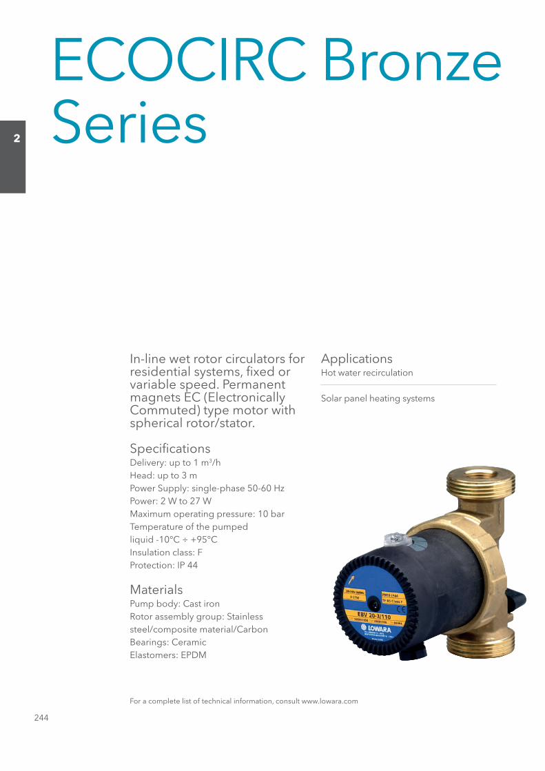
ECOCIRC Bronze Series
In-line wet rotor circulators for residential systems, fi xed orvariable speed. Permanent magnets EC (Electronically Commuted) type motor with spherical rotor/stator.
Specifi cationsDelivery: up to 1 m3/hHead: up to 3 mPower Supply: single-phase 50-60 HzPower: 2 W to 27 WMaximum operating pressure: 10 barTemperature of the pumpedliquid -10°C ÷ +95°CInsulation class: FProtection: IP 44
MaterialsPump body: Cast ironRotor assembly group: Stainlesssteel/composite material/CarbonBearings: CeramicElastomers: EPDM
ApplicationsHot water recirculation
Solar panel heating systems
For a complete list of technical information, consult www.lowara.com
Sezione_02_uk.indd 244Sezione_02_uk.indd 244 07/03/12 16.1407/03/12 16.14
245
2
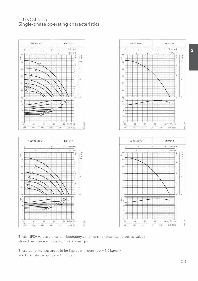
EB (V) SERIESSingle-phase operating characteristics
These NPSH values are valid in laboratory conditions; for practical purposes, values should be increased by a 0.5 m safety margin.
These performances are valid for liquids with density ρ = 1.0 kg/dm3 and kinematic viscosity ν = 1 mm2/s.
Sezione_02_uk.indd 245Sezione_02_uk.indd 245 07/03/12 16.1407/03/12 16.14

246
2
EB (V) SERIESSingle-phase operating characteristics
These NPSH values are valid in laboratory conditions; for practical purposes, values should be increased by a 0.5 m safety margin.
These performances are valid for liquids with density ρ = 1.0 kg/dm3 and kinematic viscosity ν = 1 mm2/s.
Sezione_02_uk.indd 246Sezione_02_uk.indd 246 07/03/12 16.1507/03/12 16.15

247
2
EB (V) SERIESSingle-phase operating characteristics
These NPSH values are valid in laboratory conditions; for practical purposes, values should be increased by a 0.5 m safety margin.
These performances are valid for liquids with density ρ = 1.0 kg/dm3 and kinematic viscosity ν = 1 mm2/s.
Sezione_02_uk.indd 247Sezione_02_uk.indd 247 07/03/12 16.1507/03/12 16.15
248
2
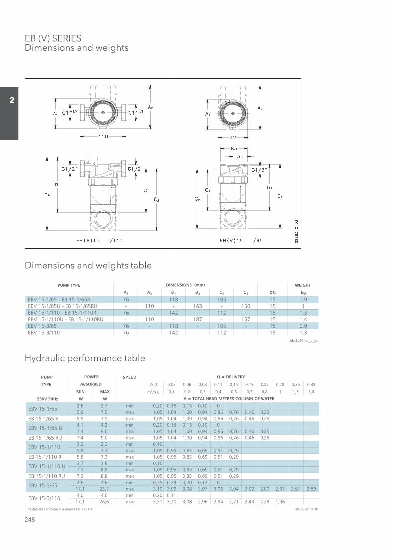
EB (V) SERIESDimensions and weights
Dimensions and weights table
PUMP TYPE WEIGHT
A1 A2 B1 B2 C1 C2 DN kg
EBV 15-1/65 - EB 15-1/65R 76 - 118 - 105 - 15 0,9 EBV 15-1/65U - EB 15-1/65RU - 110 - 163 - 150 15 1 EBV 15-1/110 - EB 15-1/110R 76 - 142 - 112 - 15 1,3 EBV 15-1/110U - EB 15-1/110RU - 110 - 187 - 157 15 1,4
9,051-501-811-6756/3-51 VBE 3,151-211-241-67011/3-51 VBE
eb-2p50-en_c_td
DIMENSIONS (mm)
Hydraulic performance table
DEEPSPMUP
TYPE l/s 0 0,03 0,06 0,08 0,11 0,14 0,19 0,22 0,28 0,36 0,39
MIN MAX m3/h 0 0,1 0,2 0,3 0,4 0,5 0,7 0,8 1 1,3 1,4
230V 50Hz W W
2,6 2,7 min 0,20 0,18 0,15 0,10 05,9 7,5 max 1,05 1,04 1,00 0,94 0,86 0,76 0,46 0,25
EB 15-1/65 R 5,9 7,5 max 1,05 1,04 1,00 0,94 0,86 0,76 0,46 0,254,1 4,2 min 0,20 0,18 0,15 0,10 07,4 9,0 max 1,05 1,04 1,00 0,94 0,86 0,76 0,46 0,25
EB 15-1/65 RU 7,4 9,0 max 1,05 1,04 1,00 0,94 0,86 0,76 0,46 0,252,2 2,3 min 0,105,8 7,3 max 1,05 0,95 0,83 0,69 0,51 0,29
EB 15-1/110 R 5,8 7,3 max 1,05 0,95 0,83 0,69 0,51 0,293,7 3,8 min 0,107,3 8,8 max 1,05 0,95 0,83 0,69 0,51 0,29
EB 15-1/110 RU 7,3 8,8 max 1,05 0,95 0,83 0,69 0,51 0,292,6 2,6 min 0,25 0,24 0,20 0,12 0
17,1 23,7 max 3,10 3,09 3,08 3,07 3,06 3,04 3,02 3,00 2,97 2,91 2,894,0 4,0 min 0,20 0,11
17,1 26,6 max 3,31 3,20 3,08 2,96 2,84 2,71 2,43 2,28 1,96Prestazioni conformi alle norme EN 1151-1 eb-50-en_d_th
EBV 15-1/65
EBV 15-1/65 U
Q = DELIVERY
H = TOTAL HEAD METRES COLUMN OF WATER
POWER
ABSORBED
EBV 15-1/110
EBV 15-1/110 U
EBV 15-3/65
EBV 15-3/110
Sezione_02_uk.indd 248Sezione_02_uk.indd 248 07/03/12 16.1507/03/12 16.15
249
2
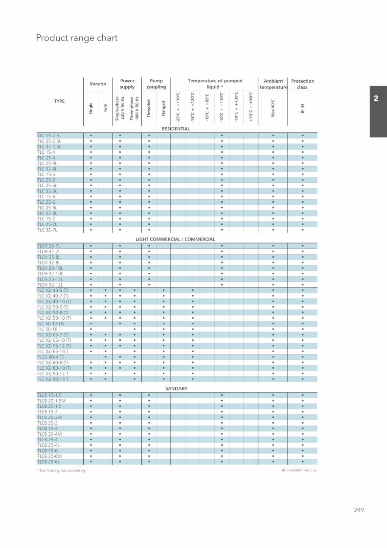
Product range chart
Ambient temperature
Protection class
Sin
gle
Twin
Sin
gle
-ph
ase
230
V 5
0 H
z
Thre
e-p
has
e
40
0 V
50
Hz
Thre
aded
Flan
ged
-25°
C ÷
+11
0°C
-15°
C ÷
+12
0°C
-10°
C ÷
+95
°C
-10°
C ÷
+11
0°C
-10
°C ÷
+13
0°C
+15
°C ÷
+90
°C
Max
40°
C
IP 4
4
TLC 15-2.5TLC 25-2.5LTLC 32-2.5LTLC 15-4TLC 25-4TLC 25-4LTLC 32-4LTLC 15-5TLC 25-5TLC 25-5LTLC 32-5LTLC 15-6TLC 25-6TLC 25-6LTLC 32-6LTLC 15-7TLC 25-7LTLC 32-7L
TLCH 25-7LTLCH 32-7LTLCH 25-8LTLCH 32-8LTLCH 25-10LTLCH 32-10LTLCH 25-12LTLCH 32-12LFLC (G) 40-5 (T)FLC (G) 40-7 (T)FLC (G) 40-10 (T)FLC (G) 50-5 (T)FLC (G) 50-8 (T)FLC (G) 50-10 (T)FLC 50-13 (T)FLC 50-18 TFLC (G) 65-7 (T)FLC (G) 65-10 (T)FLC (G) 65-12 (T)FLC (G) 65-16 TFLCG 80-4 (T)FLC (G) 80-8 (T)FLC (G) 80-10 (T)FLC (G) 80-12 TFLC (G) 80-15 T
TLCB 15-1.5TLCB 20-1.5MTLCB 25-1.5TLCB 15-3TLCB 20-3MTLCB 25-3TLCB 15-4TLCB 20-4MTLCB 25-4TLCB 25-4LTLCB 15-6TLCB 20-6MTLCB 25-6L
* Non-freezing, non-condensing. tlcflc-modelli-1-en_c_sc
SANITARY
TYPE
RESIDENTIAL
LIGHT COMMERCIAL / COMMERCIAL
VersionPower supply
Pump coupling
Temperature of pumped liquid *
Sezione_02_uk.indd 249Sezione_02_uk.indd 249 07/03/12 16.1507/03/12 16.15
250
2
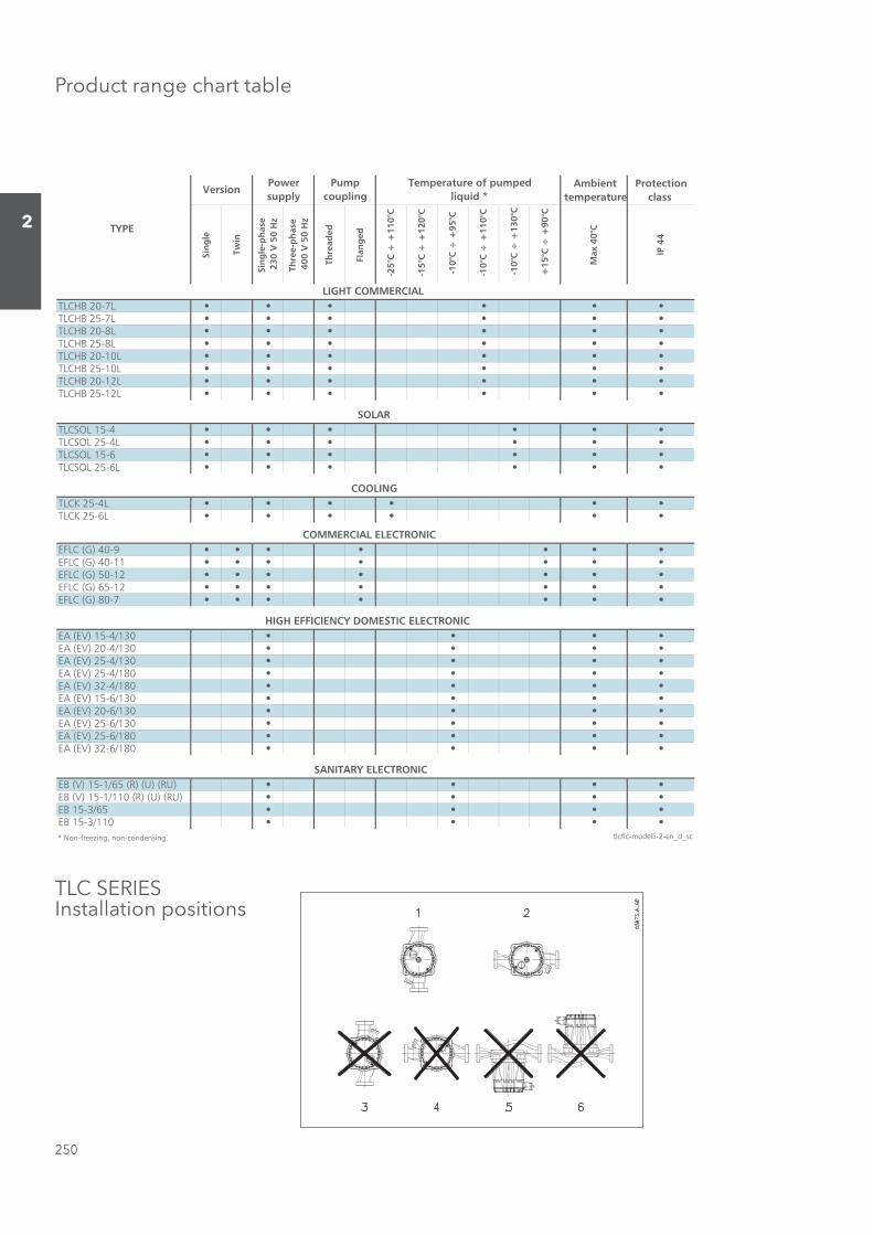
Product range chart table
Ambient temperature
Protection class
Sin
gle
Twin
Sin
gle
-ph
ase
230
V 5
0 H
z
Thre
e-p
has
e
40
0 V
50
Hz
Thre
aded
Flan
ged
-25°
C ÷
+11
0°C
-15°
C ÷
+12
0°C
-10°
C ÷
+95
°C
-10°
C ÷
+11
0°C
-10
°C ÷
+13
0°C
+15
°C ÷
+90
°C
Max
40°
C
IP 4
4
TLCHB 20-7LTLCHB 25-7LTLCHB 20-8LTLCHB 25-8LTLCHB 20-10LTLCHB 25-10LTLCHB 20-12LTLCHB 25-12L
TLCSOL 15-4TLCSOL 25-4LTLCSOL 15-6TLCSOL 25-6L
TLCK 25-4LTLCK 25-6L
EFLC (G) 40-9EFLC (G) 40-11EFLC (G) 50-12EFLC (G) 65-12EFLC (G) 80-7
EA (EV) 15-4/130EA (EV) 20-4/130EA (EV) 25-4/130EA (EV) 25-4/180EA (EV) 32-4/180EA (EV) 15-6/130EA (EV) 20-6/130EA (EV) 25-6/130EA (EV) 25-6/180EA (EV) 32-6/180
EB (V) 15-1/65 (R) (U) (RU)EB (V) 15-1/110 (R) (U) (RU)EB 15-3/65EB 15-3/110* Non-freezing, non-condensing. tlcflc-modelli-2-en_d_sc
SOLAR
COMMERCIAL ELECTRONIC
HIGH EFFICIENCY DOMESTIC ELECTRONIC
SANITARY ELECTRONIC
COOLING
TYPE
LIGHT COMMERCIAL
VersionPower supply
Pump coupling
Temperature of pumped liquid *
TLC SERIESInstallation positions
Sezione_02_uk.indd 250Sezione_02_uk.indd 250 07/03/12 16.1507/03/12 16.15
251
2
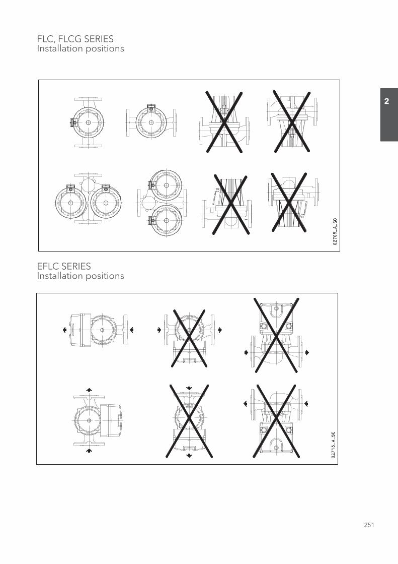
FLC, FLCG SERIESInstallation positions
EFLC SERIESInstallation positions
Sezione_02_uk.indd 251Sezione_02_uk.indd 251 07/03/12 16.1507/03/12 16.15

252
2
EFLCG SERIESInstallation positions
EA - EV (ECOCIRC) SERIESInstallation positions
Sezione_02_uk.indd 252Sezione_02_uk.indd 252 07/03/12 16.1507/03/12 16.15
253
2
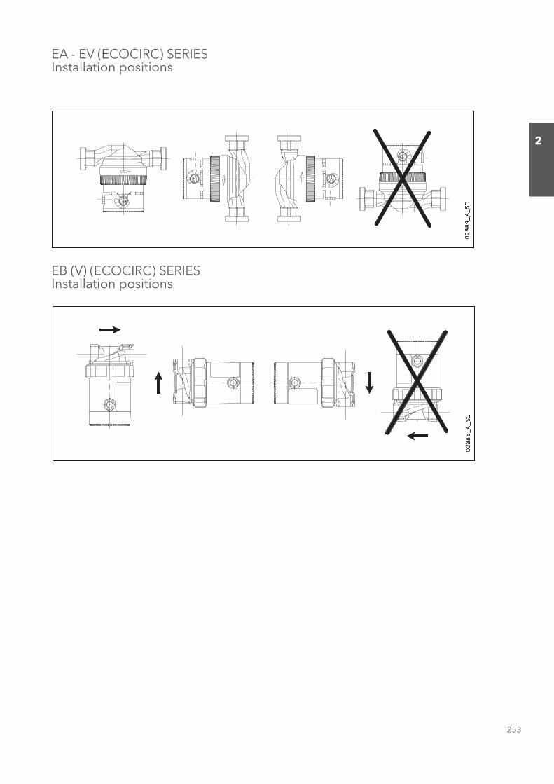
EA - EV (ECOCIRC) SERIESInstallation positions
EB (V) (ECOCIRC) SERIESInstallation positions
Sezione_02_uk.indd 253Sezione_02_uk.indd 253 07/03/12 16.1507/03/12 16.15
254
2
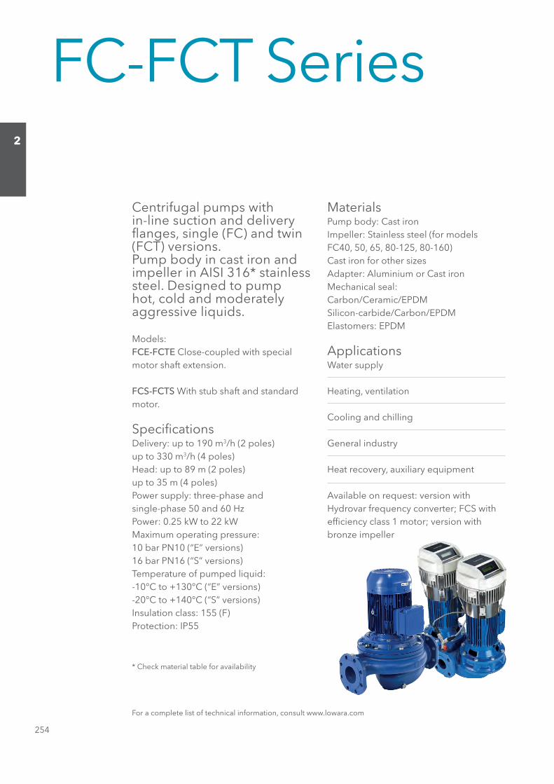
FC-FCT Series
Centrifugal pumps within-line suction and delivery fl anges, single (FC) and twin (FCT) versions.Pump body in cast iron and impeller in AISI 316* stainless steel. Designed to pump hot, cold and moderately aggressive liquids.
Models:FCE-FCTE Close-coupled with special motor shaft extension.
FCS-FCTS With stub shaft and standard motor.
Specifi cationsDelivery: up to 190 m3/h (2 poles)up to 330 m3/h (4 poles)Head: up to 89 m (2 poles)up to 35 m (4 poles)Power supply: three-phase andsingle-phase 50 and 60 HzPower: 0.25 kW to 22 kWMaximum operating pressure:10 bar PN10 (“E” versions)16 bar PN16 (“S” versions)Temperature of pumped liquid:-10°C to +130°C (“E” versions)-20°C to +140°C (“S” versions)Insulation class: 155 (F)Protection: IP55
MaterialsPump body: Cast ironImpeller: Stainless steel (for modelsFC40, 50, 65, 80-125, 80-160)Cast iron for other sizesAdapter: Aluminium or Cast ironMechanical seal:Carbon/Ceramic/EPDMSilicon-carbide/Carbon/EPDMElastomers: EPDM
ApplicationsWater supply
Heating, ventilation
Cooling and chilling
General industry
Heat recovery, auxiliary equipment
Available on request: version withHydrovar frequency converter; FCS witheffi ciency class 1 motor; version withbronze impeller
For a complete list of technical information, consult www.lowara.com
* Check material table for availability
Sezione_02_uk.indd 254Sezione_02_uk.indd 254 07/03/12 16.1507/03/12 16.15
255
2
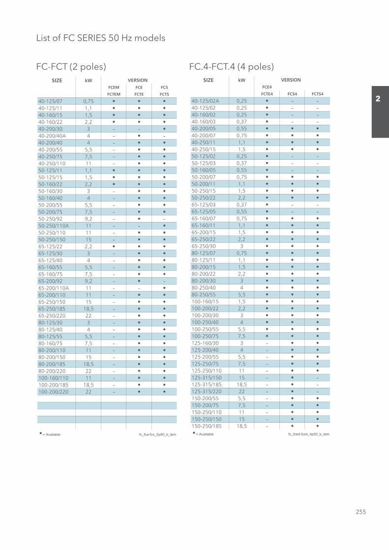
List of FC SERIES 50 Hz models
FC-FCT (2 poles) FC.4-FCT.4 (4 poles)SIZE kW
FCEM FCE FCS
FCTEM FCTE FCTS
40-125/07 0,7540-125/11 1,140-160/15 1,540-160/22 2,240-200/30 3 - -40-200/40A 4 - -40-200/40 4 -40-200/55 5,5 -40-250/75 7,5 -40-250/110 11 -50-125/11 1,150-125/15 1,550-160/22 2,250-160/30 3 -50-160/40 4 -50-200/55 5,5 -50-200/75 7,5 -50-250/92 9,2 - -50-250/110A 11 - -50-250/110 11 -50-250/150 15 -65-125/22 2,265-125/30 3 -65-125/40 4 -65-160/55 5,5 -65-160/75 7,5 -65-200/92 9,2 - -65-200/110A 11 - -65-200/110 11 -65-250/150 15 -65-250/185 18,5 -65-250/220 22 -80-125/30 3 -80-125/40 4 -80-125/55 5,5 -80-160/75 7,5 -80-200/110 11 -80-200/150 15 -80-200/185 18,5 -80-200/220 22 -100-160/110 11 -100-200/185 18,5 -100-200/220 22 -
= Available fc_fce-fcs_2p50_b_tem
VERSION SIZE kWFCE4
FCTE4 FCS4 FCTS4
40-125/02A 0,25 - -40-125/02 0,25 - -40-160/02 0,25 - -40-160/03 0,37 - -40-200/05 0,5540-200/07 0,7540-250/11 1,140-250/15 1,550-125/02 0,25 - -50-125/03 0,37 - -50-160/05 0,55 - -50-200/07 0,7550-200/11 1,150-250/15 1,550-250/22 2,265-125/03 0,37 - -65-125/05 0,55 - -65-160/07 0,7565-160/11 1,165-200/15 1,565-250/22 2,265-250/30 380-125/07 0,7580-125/11 1,180-200/15 1,580-200/22 2,280-200/30 380-250/40 480-250/55 5,5100-160/15 1,5100-200/22 2,2100-200/30 3100-250/40 4100-250/55 5,5100-250/75 7,5125-160/30 3 -125-200/40 4 -125-200/55 5,5 -125-250/75 7,5 -125-250/110 11 -125-315/150 15 - -125-315/185 18,5 - -125-315/220 22 - -150-200/55 5,5 -150-200/75 7,5 -150-250/110 11 -150-250/150 15 -150-250/185 18,5 -
= Available fc_fce4-fcs4_4p50_b_tem
VERSION
Sezione_02_uk.indd 255Sezione_02_uk.indd 255 07/03/12 16.1507/03/12 16.15

256
2
PUMP
TYPE l/min 0 100 200 350 375 400 600 700 800 850 1000 1200 1300 1500 1600 1750 1950 2500 3000
m3/h 0 6 12 21 22,5 24 36 42 48 51 60 72 78 90 96 105 117 150 180
kW HP
40-125/07 0,75 1 17,1 15,1 11,8 3,6
40-125/11 1,1 1,5 22,6 20,2 16,7 8,8 7,0
40-160/15 1,5 2 27,3 24,7 20,9 13,1 11,3 9,3
40-160/22 2,2 3 35,3 32,6 28,8 21,1 19,5 17,7
40-200/* * * 42,5 38,9 34,0
40-200/40 4 5,5 51,0 46,9 41,7 30,6
40-200/55 5,5 7,5 62,0 57,6 51,3 39,6 37,1
40-250/75 7,5 10 75,4 71,1 65,0 52,9 50,3
40-250/110 11 15 85,2 80,8 74,8 62,3 59,6 56,6
50-125/11/A 1,1 1,5 15,3 13,5 11,1 10,6 10,1 5,4
50-125/15/A 1,5 2 19,1 17,5 14,9 14,4 13,8 8,6 5,5
50-160/22 2,2 3 26,1 23,9 21,1 20,5 20,0 14,7 11,6
50-160/30 3 4 32,8 30,6 27,2 26,5 25,9 19,9 16,6 13,1
50-160/40 4 5,5 38,1 36,1 32,9 32,3 31,6 25,1 21,3 17,3 15,3
50-200/55 5,5 7,5 47,0 43,5 39,6 38,8 38,0 30,3
50-200/75 7,5 10 56,0 52,0 48,2 47,5 46,7 39,4 34,9
50-250/** ** ** 63,2 59,4 55,3 54,5 53,8 46,7 42,6 38,0
50-250/110 11 15 69,4 65,3 61,3 60,6 59,8 53,2 49,4 45,0 42,5
50-250/150 15 20 83,0 79,2 75,1 74,4 73,6 66,1 61,6 56,6 53,9
65-125/22 2,2 3 18,8 16,4 14,3 13,0 11,4 10,6 7,9
65-125/30 3 4 22,9 20,3 18,1 16,7 15,2 14,3 11,6
65-125/40 4 5,5 26,6 24,4 22,4 21,1 19,7 18,9 16,3 12,1
65-160/55 5,5 7,5 35,1 32,5 30,1 28,7 27,1 26,3 23,5 19,1
65-160/75 7,5 10 42,4 40,0 37,4 35,8 34,0 33,1 29,9 25,2 22,5
65-200/** ** ** 53,0 47,6 44,1 42,2 40,1 39,0 35,2 28,4 24,0
65-200/110 11 15 61,0 55,2 51,3 49,3 47,1 45,9 42,1 35,8 31,8
65-250/150 15 20 70,0 66,3 63,0 61,1 58,9 57,8 54,2 48,9 46,1 40,0
65-250/185 18,5 25 80,0 75,2 71,8 69,9 67,7 66,6 63,0 57,6 54,6 47,9
65-250/220 22 30 89,0 84,3 80,7 78,7 76,5 75,3 71,6 66,0 63,0 56,3 52,6
80-125/30 3 4 15,5 14,5 14,1 13,6 13,3 12,3 10,7 9,9
80-125/40 4 5,5 19,0 18,0 17,6 17,0 16,8 15,8 14,2 13,3 11,5
80-125/55 5,5 7,5 23,0 21,5 21,0 20,5 20,2 19,3 18,0 17,2 15,5 14,5
80-160/75 7,5 10 28,0 26,5 26,1 25,6 25,4 24,7 23,6 23,0 21,6 20,8 19,5
80-200/110 11 15 41,0 37,0 36,2 35,2 34,7 33,2 30,7 29,3 26,2 24,5 21,5
80-200/150 15 20 49,4 46,3 45,6 44,8 44,3 43,0 41,0 39,9 37,5 36,2 33,9 30,5
80-200/185 18,5 25 56,9 53,4 52,6 51,7 51,2 49,8 47,9 46,9 44,7 43,5 41,4 38,1
80-200/220 22 30 65,2 61,3 60,4 59,5 59,0 57,6 55,5 54,5 52,2 51,0 49,1 46,0
100-160/110 11 15 29,0 28,0 27,3 26,9 25,9 25,4 24,6 23,4 19,5
100-200/185 18,5 25 45,0 39,5 38,8 37,5 36,8 35,9 34,5 30,4 25,0
100-200/220 22 30 53,0 48,0 47,3 46,0 45,3 44,3 42,9 38,7 33,6)PH( 4 - )Wk( 3 : 03/002-04SCF)PH( 5.5 - )Wk( 4 : A04/002-04ECF * fce-fcs-2p50-en_d_th
)PH( 51 - )Wk( 11 : A011/052-05SCF)PH( 5.21 - )Wk( 2.9 : 29/052-05ECF **
)PH( 51 - )Wk( 11 : A011/002-56SCF)PH( 5.21 - )Wk( 2.9 : 29/002-56ECF
Performances according to ISO 9906 - Annex A
RATED
POWER
Q = DELIVERY
H = TOTAL HEAD METRES COLUMN OF WATER
FCE-FCS SERIESHydraulic performance table at 50 Hz, 2 poles
Sezione_02_uk.indd 256Sezione_02_uk.indd 256 07/03/12 16.1507/03/12 16.15
257
2
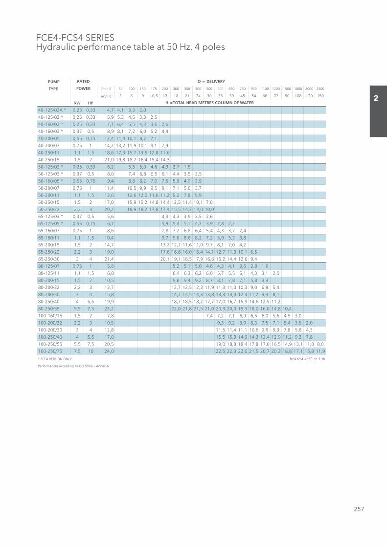
FCE4-FCS4 SERIESHydraulic performance table at 50 Hz, 4 poles
PUMP
TYPE l/min 0 50 100 150 175 200 300 350 400 500 600 650 750 900 1100 1200 1500 1800 2000 2500
m3/h 0 3 6 9 10,5 12 18 21 24 30 36 39 45 54 66 72 90 108 120 150
kW HP
40-125/02A * 0,25 0,33 4,7 4,1 3,3 2,0
40-125/02 * 0,25 0,33 5,9 5,3 4,5 3,3 2,5
40-160/02 * 0,25 0,33 7,1 6,4 5,5 4,3 3,6 2,6
40-160/03 * 0,37 0,5 8,9 8,1 7,2 6,0 5,2 4,4
40-200/05 0,55 0,75 12,4 11,4 10,1 8,2 7,1
40-200/07 0,75 1 14,2 13,2 11,9 10,1 9,1 7,9
40-250/11 1,1 1,5 18,6 17,3 15,7 13,9 12,8 11,6
40-250/15 1,5 2 21,0 19,8 18,2 16,4 15,4 14,3
50-125/02 * 0,25 0,33 6,2 5,5 5,0 4,6 4,3 2,7 1,8
50-125/03 * 0,37 0,5 8,0 7,4 6,8 6,5 6,1 4,4 3,5 2,5
50-160/05 * 0,55 0,75 9,4 8,8 8,2 7,9 7,5 5,9 4,9 3,9
50-200/07 0,75 1 11,4 10,5 9,9 9,5 9,1 7,1 5,6 3,7
50-200/11 1,1 1,5 13,6 12,6 12,0 11,6 11,2 9,2 7,8 5,9
50-250/15 1,5 2 17,0 15,9 15,2 14,8 14,4 12,5 11,4 10,1 7,0
50-250/22 2,2 3 20,2 18,9 18,2 17,8 17,4 15,5 14,3 13,0 10,0
65-125/03 * 0,37 0,5 5,6 4,9 4,3 3,9 3,5 2,6
65-125/05 * 0,55 0,75 6,7 5,9 5,4 5,1 4,7 3,9 2,8 2,2
65-160/07 0,75 1 8,6 7,8 7,2 6,8 6,4 5,4 4,3 3,7 2,4
65-160/11 1,1 1,5 10,4 9,7 9,0 8,6 8,2 7,2 5,9 5,3 3,8
65-200/15 1,5 2 14,7 13,2 12,1 11,6 11,0 9,7 8,1 7,0 4,2
65-250/22 2,2 3 19,0 17,6 16,6 16,0 15,4 14,1 12,7 11,9 10,1 6,5
65-250/30 3 4 21,4 20,1 19,1 18,5 17,9 16,6 15,2 14,4 12,6 9,4
80-125/07 0,75 1 5,6 5,2 5,1 5,0 4,6 4,3 4,1 3,6 2,8 1,6
80-125/11 1,1 1,5 6,8 6,4 6,3 6,2 6,0 5,7 5,5 5,1 4,3 3,1 2,5
80-200/15 1,5 2 10,5 9,6 9,4 9,2 8,7 8,1 7,8 7,1 5,8 3,3
80-200/22 2,2 3 13,7 12,7 12,5 12,3 11,9 11,3 11,0 10,3 9,0 6,8 5,4
80-200/30 3 4 15,8 14,7 14,5 14,3 13,8 13,3 13,0 12,4 11,2 9,3 8,1
80-250/40 4 5,5 19,9 18,7 18,5 18,2 17,7 17,0 16,7 15,9 14,6 12,5 11,2
80-250/55 5,5 7,5 23,2 22,0 21,8 21,5 21,0 20,3 20,0 19,3 18,0 16,0 14,8 10,4
100-160/15 1,5 2 7,8 7,4 7,2 7,1 6,9 6,5 6,0 5,6 4,5 3,0
100-200/22 2,2 3 10,5 9,3 9,2 8,9 8,3 7,5 7,1 5,4 3,5 2,0
100-200/30 3 4 12,8 11,5 11,4 11,1 10,6 9,8 9,3 7,8 5,8 4,3
100-250/40 4 5,5 17,0 15,5 15,3 14,9 14,3 13,4 12,9 11,2 9,2 7,8
100-250/55 5,5 7,5 20,5 19,0 18,8 18,4 17,8 17,0 16,5 14,9 13,1 11,8 8,0
100-250/75 7,5 10 24,0 22,5 22,3 22,0 21,5 20,7 20,3 18,8 17,1 15,8 11,9
* FCE4 VERSION ONLY fce4-fcs4-4p50-en_f_th
Performances according to ISO 9906 - Annex A
RATED
POWER
Q = DELIVERY
H =TOTAL HEAD METRES COLUMN OF WATER
Sezione_02_uk.indd 257Sezione_02_uk.indd 257 07/03/12 16.1507/03/12 16.15

258
2
FCS4 SERIESHydraulic performance table at 50 Hz, 4 poles
PUMP
TYPE l/min 0 1000 1083 1167 1333 1500 1667 2000 2333 2667 3000 3333 3667 4167 4667 5000 5333 5500
m3/h 0 60 65 70 80 90 100 120 140 160 180 200 220 250 280 300 320 330
kW HP
125-160/30 3 4 10,5 9,2 9,0 8,8 8,3 7,9 7,4 6,3 5,2 3,7 2,0
125-200/40 4 5,5 12,7 11,5 11,3 11,0 10,5 9,9 9,3 7,7 5,7 3,4
125-200/55 5,5 7,5 15,6 14,6 14,4 14,3 13,9 13,4 12,9 11,6 10,0 8,0 5,5
125-250/75 7,5 10 20,5 19,1 18,9 18,6 18,1 17,4 16,6 14,7 12,4 9,6 6,7
125-250/110 11 15 26,1 24,8 24,6 24,4 23,9 23,4 22,7 21,1 19,2 16,8 14,0 10,7 7,1
125-315/150 15 20 27,0 26,0 25,9 25,7 25,4 25,0 24,6 23,5 22,1 20,4 18,3 15,9 12,9 7,8
125-315/185 18,5 25 31,0 30,0 29,9 29,8 29,5 29,2 28,9 28,0 26,7 25,1 23,1 20,7 18,0 13,3 8,0
125-315/220 22 30 35,0 34,0 33,9 33,8 33,6 33,3 32,9 32,1 30,9 29,5 27,6 25,5 22,9 18,4 12,9 8,8
150-200/55 5,5 7,5 12,0 10,5 10,4 10,2 9,9 9,6 9,3 8,6 7,9 7,2 6,4 5,7 4,8 3,2
150-200/75 7,5 10 16,0 14,8 14,6 14,4 14,1 13,7 13,4 12,6 11,9 11,1 10,3 9,5 8,6 6,9 4,7
150-250/110 11 15 18,4 17,8 17,6 17,0 16,3 15,5 14,6 13,5 12,3 10,2 7,7 5,8
150-250/150 15 20 22,4 22,0 21,8 21,3 20,7 20,0 19,3 18,4 17,4 15,6 13,3 11,5 9,5 8,3
150-250/185 18,5 25 25,1 24,7 24,6 24,1 23,6 23,0 22,2 21,3 20,3 18,5 16,4 14,7 13,0 12,0
Performances according to ISO 9906 - Annex A fcs4-4p50-en_d_th
RATED
POWER
Q = DELIVERY
H = TOTAL HEAD METRES COLUMN OF WATER
Black and white technical books available
see www.lowara.it
Sezione_02_uk.indd 258Sezione_02_uk.indd 258 07/03/12 16.1507/03/12 16.15
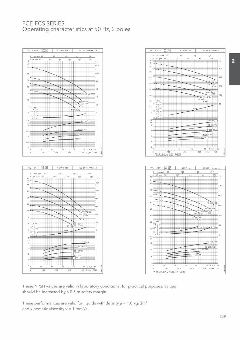
259
2
FCE-FCS SERIESOperating characteristics at 50 Hz, 2 poles
These NPSH values are valid in laboratory conditions; for practical purposes, values should be increased by a 0.5 m safety margin.
These performances are valid for liquids with density ρ = 1.0 kg/dm3 and kinematic viscosity ν = 1 mm2/s.
Sezione_02_uk.indd 259Sezione_02_uk.indd 259 07/03/12 16.1507/03/12 16.15
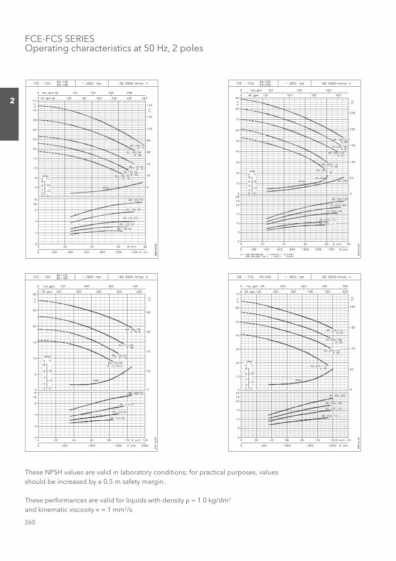
260
2
FCE-FCS SERIESOperating characteristics at 50 Hz, 2 poles
These NPSH values are valid in laboratory conditions; for practical purposes, values should be increased by a 0.5 m safety margin.
These performances are valid for liquids with density ρ = 1.0 kg/dm3 and kinematic viscosity ν = 1 mm2/s.
Sezione_02_uk.indd 260Sezione_02_uk.indd 260 07/03/12 16.1507/03/12 16.15
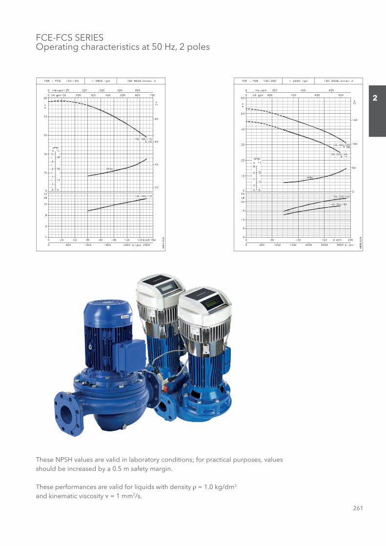
261
2
FCE-FCS SERIESOperating characteristics at 50 Hz, 2 poles
These NPSH values are valid in laboratory conditions; for practical purposes, values should be increased by a 0.5 m safety margin.
These performances are valid for liquids with density ρ = 1.0 kg/dm3 and kinematic viscosity ν = 1 mm2/s.
Sezione_02_uk.indd 261Sezione_02_uk.indd 261 07/03/12 16.1507/03/12 16.15
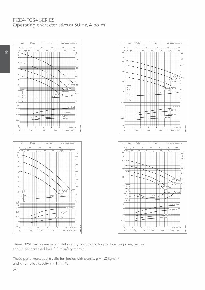
262
2
FCE4-FCS4 SERIESOperating characteristics at 50 Hz, 4 poles
These NPSH values are valid in laboratory conditions; for practical purposes, values should be increased by a 0.5 m safety margin.
These performances are valid for liquids with density ρ = 1.0 kg/dm3 and kinematic viscosity ν = 1 mm2/s.
Sezione_02_uk.indd 262Sezione_02_uk.indd 262 07/03/12 16.1507/03/12 16.15
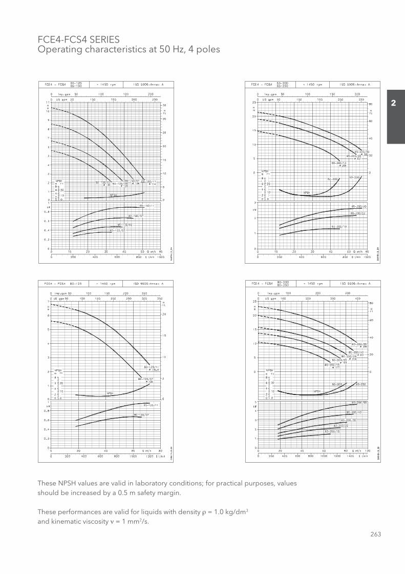
263
2
FCE4-FCS4 SERIESOperating characteristics at 50 Hz, 4 poles
These NPSH values are valid in laboratory conditions; for practical purposes, values should be increased by a 0.5 m safety margin.
These performances are valid for liquids with density ρ = 1.0 kg/dm3 and kinematic viscosity ν = 1 mm2/s.
Sezione_02_uk.indd 263Sezione_02_uk.indd 263 07/03/12 16.1507/03/12 16.15
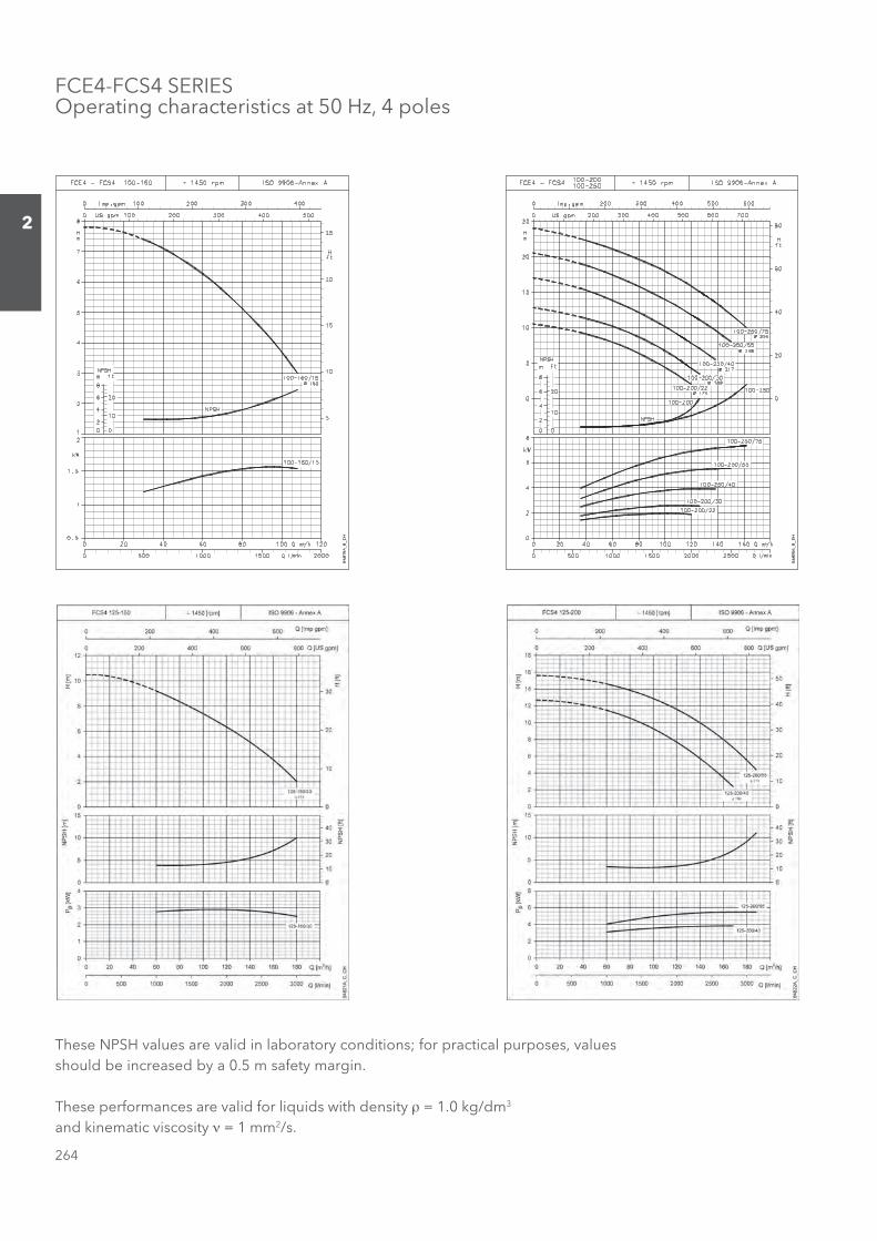
264
2
FCE4-FCS4 SERIESOperating characteristics at 50 Hz, 4 poles
These NPSH values are valid in laboratory conditions; for practical purposes, values should be increased by a 0.5 m safety margin.
These performances are valid for liquids with density ρ = 1.0 kg/dm3 and kinematic viscosity ν = 1 mm2/s.
Sezione_02_uk.indd 264Sezione_02_uk.indd 264 07/03/12 16.1507/03/12 16.15
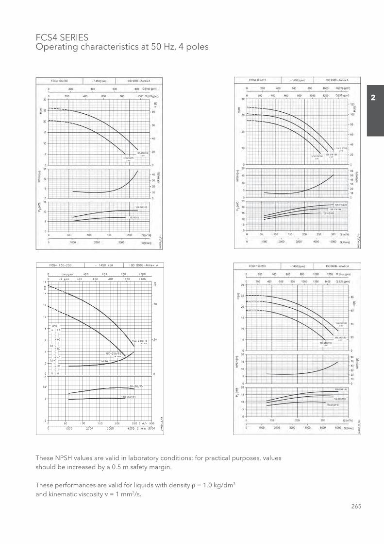
265
2
FCS4 SERIESOperating characteristics at 50 Hz, 4 poles
These NPSH values are valid in laboratory conditions; for practical purposes, values should be increased by a 0.5 m safety margin.
These performances are valid for liquids with density ρ = 1.0 kg/dm3 and kinematic viscosity ν = 1 mm2/s.
Sezione_02_uk.indd 265Sezione_02_uk.indd 265 07/03/12 16.1507/03/12 16.15
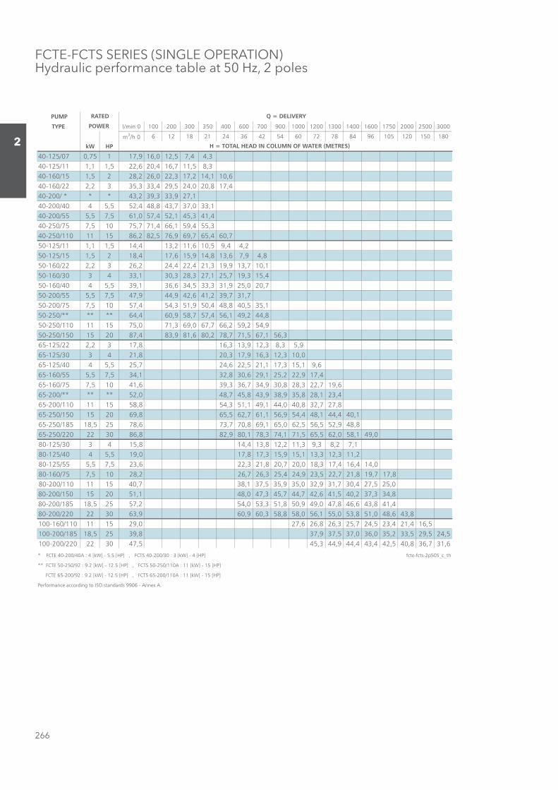
266
2
FCTE-FCTS SERIES (SINGLE OPERATION)Hydraulic performance table at 50 Hz, 2 poles
PUMP
TYPE l/min 0 100 200 300 350 400 600 700 900 1000 1200 1300 1400 1600 1750 2000 2500 3000
m3/h 0 6 12 18 21 24 36 42 54 60 72 78 84 96 105 120 150 180
kW HP
40-125/07 0,75 1 17,9 16,0 12,5 7,4 4,340-125/11 1,1 1,5 22,6 20,4 16,7 11,5 8,340-160/15 1,5 2 28,2 26,0 22,3 17,2 14,1 10,640-160/22 2,2 3 35,3 33,4 29,5 24,0 20,8 17,440-200/ * * * 43,2 39,3 33,9 27,140-200/40 4 5,5 52,4 48,8 43,7 37,0 33,140-200/55 5,5 7,5 61,0 57,4 52,1 45,3 41,440-250/75 7,5 10 75,7 71,4 66,1 59,4 55,340-250/110 11 15 86,2 82,5 76,9 69,7 65,4 60,750-125/11 1,1 1,5 14,4 13,2 11,6 10,5 9,4 4,250-125/15 1,5 2 18,4 17,6 15,9 14,8 13,6 7,9 4,850-160/22 2,2 3 26,2 24,4 22,4 21,3 19,9 13,7 10,150-160/30 3 4 33,1 30,3 28,3 27,1 25,7 19,3 15,450-160/40 4 5,5 39,1 36,6 34,5 33,3 31,9 25,0 20,750-200/55 5,5 7,5 47,9 44,9 42,6 41,2 39,7 31,750-200/75 7,5 10 57,4 54,3 51,9 50,4 48,8 40,5 35,150-250/** ** ** 64,4 60,9 58,7 57,4 56,1 49,2 44,850-250/110 11 15 75,0 71,3 69,0 67,7 66,2 59,2 54,950-250/150 15 20 87,4 83,9 81,6 80,2 78,7 71,5 67,1 56,365-125/22 2,2 3 17,8 16,3 13,9 12,3 8,3 5,965-125/30 3 4 21,8 20,3 17,9 16,3 12,3 10,065-125/40 4 5,5 25,7 24,6 22,5 21,1 17,3 15,1 9,665-160/55 5,5 7,5 34,1 32,8 30,6 29,1 25,2 22,9 17,465-160/75 7,5 10 41,6 39,3 36,7 34,9 30,8 28,3 22,7 19,665-200/** ** ** 52,0 48,7 45,8 43,9 38,9 35,8 28,1 23,465-200/110 11 15 58,8 54,3 51,1 49,1 44,0 40,8 32,7 27,865-250/150 15 20 69,8 65,5 62,7 61,1 56,9 54,4 48,1 44,4 40,165-250/185 18,5 25 78,6 73,7 70,8 69,1 65,0 62,5 56,5 52,9 48,865-250/220 22 30 86,8 82,9 80,1 78,3 74,1 71,5 65,5 62,0 58,1 49,080-125/30 3 4 15,8 14,4 13,8 12,2 11,3 9,3 8,2 7,180-125/40 4 5,5 19,0 17,8 17,3 15,9 15,1 13,3 12,3 11,280-125/55 5,5 7,5 23,6 22,3 21,8 20,7 20,0 18,3 17,4 16,4 14,080-160/75 7,5 10 28,2 26,7 26,3 25,4 24,9 23,5 22,7 21,8 19,7 17,880-200/110 11 15 40,7 38,1 37,5 35,9 35,0 32,9 31,7 30,4 27,5 25,080-200/150 15 20 51,1 48,0 47,3 45,7 44,7 42,6 41,5 40,2 37,3 34,880-200/185 18,5 25 57,2 54,0 53,3 51,8 50,9 49,0 47,8 46,6 43,8 41,480-200/220 22 30 63,9 60,9 60,3 58,8 58,0 56,1 55,0 53,8 51,0 48,6 43,8100-160/110 11 15 29,0 27,6 26,8 26,3 25,7 24,5 23,4 21,4 16,5100-200/185 18,5 25 39,8 37,9 37,5 37,0 36,0 35,2 33,5 29,5 24,5100-200/220 22 30 47,5 45,3 44,9 44,4 43,4 42,5 40,8 36,7 31,6
* FCTE 40-200/40A : 4 [kW] - 5.5 [HP] , FCTS 40-200/30 : 3 [kW] - 4 [HP] fcte-fcts-2p50S_c_th
** FCTE 50-250/92 : 9.2 [kW] - 12.5 [HP] , FCTS 50-250/110A : 11 [kW] - 15 [HP]
FCTE 65-200/92 : 9.2 [kW] - 12.5 [HP] , FCTS 65-200/110A : 11 [kW] - 15 [HP]
Performance according to ISO standards 9906 - Annex A.
RATED
POWER
Q = DELIVERY
H = TOTAL HEAD IN COLUMN OF WATER (METRES)
Sezione_02_uk.indd 266Sezione_02_uk.indd 266 07/03/12 16.1507/03/12 16.15
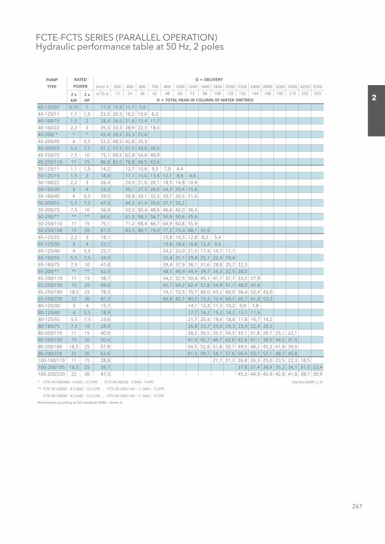
267
2
FCTE-FCTS SERIES (PARALLEL OPERATION)Hydraulic performance table at 50 Hz, 2 poles
PUMP
TYPE l/min 0 200 400 600 700 800 1000 1200 1600 1800 2000 2200 2400 2800 3200 3500 4250 5550
2 x 2 x m3/h 0 12 24 36 42 48 60 72 96 108 120 132 144 168 192 210 255 333
kW HP
40-125/07 0,75 1 17,9 15,9 11,7 5,640-125/11 1,1 1,5 23,0 20,5 16,2 10,0 6,340-160/15 1,5 2 28,4 26,0 21,6 15,4 11,740-160/22 2,2 3 35,3 33,3 28,9 22,3 18,440-200/ * * * 43,4 39,2 33,3 25,640-200/40 4 5,5 52,5 48,5 42,8 35,340-200/55 5,5 7,5 61,2 57,5 51,5 43,6 39,040-250/75 7,5 10 75,1 69,5 62,8 54,6 49,940-250/110 11 15 86,8 83,0 76,8 68,5 63,650-125/11 1,1 1,5 14,2 12,7 10,6 9,3 7,8 4,450-125/15 1,5 2 18,4 17,1 15,0 13,6 12,1 8,6 4,650-160/22 2,2 3 26,4 24,0 21,6 20,1 18,5 14,8 10,450-160/30 3 4 33,3 30,1 27,5 26,0 24,3 20,4 15,850-160/40 4 5,5 39,5 36,8 34,1 32,5 30,7 26,5 21,650-200/55 5,5 7,5 47,6 44,2 41,4 39,6 37,7 33,250-200/75 7,5 10 56,9 53,3 50,4 48,6 46,6 42,0 36,450-250/** ** ** 64,6 61,0 58,3 56,7 54,8 50,6 45,650-250/110 11 15 75,1 71,2 68,4 66,7 64,9 60,8 55,950-250/150 15 20 87,3 83,5 80,7 79,0 77,2 73,0 68,1 55,965-125/22 2,2 3 18,1 15,8 14,5 12,8 8,3 5,465-125/30 3 4 22,1 19,8 18,4 16,8 12,4 9,665-125/40 4 5,5 25,7 24,2 23,0 21,5 17,4 14,7 11,765-160/55 5,5 7,5 34,0 32,4 31,1 29,4 25,1 22,4 19,465-160/75 7,5 10 41,8 39,4 37,9 36,1 31,6 28,8 25,7 22,365-200/** ** ** 52,0 48,5 46,9 44,9 39,7 36,3 32,5 28,065-200/110 11 15 58,7 54,2 52,5 50,4 45,1 41,7 37,7 33,2 27,965-250/150 15 20 69,6 65,7 64,2 62,4 57,8 54,9 51,7 48,0 43,865-250/185 18,5 25 78,3 74,1 72,5 70,7 66,0 63,2 60,0 56,4 52,4 43,065-250/220 22 30 87,3 83,8 82,1 80,2 75,3 72,4 69,2 65,7 61,8 53,280-125/30 3 4 15,7 14,1 12,4 11,3 10,2 9,0 7,880-125/40 4 5,5 18,9 17,7 16,2 15,2 14,2 13,1 11,980-125/55 5,5 7,5 23,6 21,7 20,4 19,6 18,8 17,8 16,7 14,280-160/75 7,5 10 28,4 26,8 25,7 25,0 24,3 23,4 22,4 20,280-200/110 11 15 40,9 38,2 36,5 35,5 34,3 33,1 31,8 28,7 25,1 22,180-200/150 15 20 50,4 47,4 45,7 44,7 43,6 42,4 41,1 38,0 34,5 31,580-200/185 18,5 25 57,8 54,5 52,8 51,8 50,7 49,5 48,2 45,3 41,9 39,080-200/220 22 30 63,6 61,3 59,7 58,7 57,6 56,4 55,1 52,1 48,7 45,8100-160/110 11 15 28,8 27,7 27,3 26,8 26,3 25,0 23,5 22,3 18,5100-200/185 18,5 25 39,7 37,8 37,4 36,4 35,2 34,1 31,0 23,4100-200/220 22 30 47,5 45,3 44,9 43,9 42,8 41,8 38,7 30,9
* FCTE 40-200/40A : 4 [kW] - 5.5 [HP] , FCTS 40-200/30 : 3 [kW] - 4 [HP] fcte-fcts-2p50P_c_th
** FCTE 50-250/92 : 9.2 [kW] - 12.5 [HP] , FCTS 50-250/110A : 11 [kW] - 15 [HP]
FCTE 65-200/92 : 9.2 [kW] - 12.5 [HP] , FCTS 65-200/110A : 11 [kW] - 15 [HP]
Performance according to ISO standards 9906 - Annex A.
RATED
POWER
Q = DELIVERY
H = TOTAL HEAD IN COLUMN OF WATER (METRES)
Sezione_02_uk.indd 267Sezione_02_uk.indd 267 07/03/12 16.1507/03/12 16.15
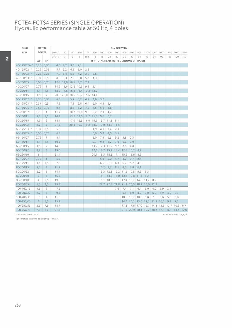
268
2
FCTE4-FCTS4 SERIES (SINGLE OPERATION)Hydraulic performance table at 50 Hz, 4 poles
PUMP
TYPE l/min 0 50 100 150 175 200 300 400 500 600 700 900 1200 1400 1600 1750 2000 2500
m3/h 0 3 6 9 10,5 12 18 24 30 36 42 54 72 84 96 105 120 150
kW HP
40-125/02A * 0,25 0,33 4,6 4,2 3,3 2,1
40-125/02 * 0,25 0,33 5,7 5,2 4,3 3,0 2,2
40-160/02 * 0,25 0,33 7,0 6,4 5,5 4,2 3,4 2,6
40-160/03 * 0,37 0,5 8,8 8,3 7,3 6,0 5,2 4,3
40-200/05 0,55 0,75 12,8 11,8 10,5 8,7 7,7
40-200/07 0,75 1 14,5 13,6 12,2 10,3 9,3 8,1
40-250/11 1,1 1,5 18,5 17,6 16,2 14,4 13,3 12,2
40-250/15 1,5 2 20,9 20,0 18,6 16,7 15,6 14,4
50-125/02 * 0,25 0,33 6,3 5,7 5,2 4,9 4,6 3,0
50-125/03 * 0,37 0,5 7,9 7,3 6,8 6,4 6,0 4,3 2,4
50-160/05 * 0,55 0,75 9,4 8,8 8,2 7,9 7,5 5,8 3,6
50-200/07 0,75 1 11,7 10,7 10,0 9,6 9,2 7,1 4,2
50-200/11 1,1 1,5 14,1 13,2 12,5 12,2 11,8 9,6 6,7
50-250/15 1,5 2 18,1 17,0 16,3 16,0 15,6 13,7 11,3 8,1
50-250/22 2,2 3 21,3 20,3 19,7 19,3 18,9 17,0 14,6 11,5
3,24,33,49,46,55,073,0* 30/521-56
5,35,44,50,64,657,055,0* 50/521-56
3,28,32,53,63,70,84,8157,070/061-56
9,36,50,72,81,97,93,015,11,111/061-56
8,46,77,92,113,212,313,4125,151/002-56
9,47,018,214,417,517,616,710,9132,222/052-56
5,86,315,511,713,813,911,024,124303/052-56
4,27,32,47,40,53,56,5157,070/521-08
0,42,57,50,63,66,60,75,11,111/521-08
1,68,75,81,97,92,017,1125,151/002-08
3,62,98,015,112,218,213,317,4132,222/002-08
2,83,118,214,310,416,411,517,614303/002-08
2,82,118,417,614,711,816,811,916,915,5404/052-08
9,216,519,815,022,128,123,227,223,325,75,555/052-08
1,29,20,40,54,61,74,76,79,725,151/061-001
3,20,49,40,60,72,89,81,97,932,222/002-001
8,36,56,68,78,80,017,019,016,114303/002-001
2,71,91,013,113,216,312,414,412,515,5404/052-001
7,69,017,216,318,417,510,716,718,717,815,75,555/052-001
0,014,411,611,712,812,914,029,022,126,12015,757/052-001
* FCTE4 VERSION ONLY fcte4-fcts4-4p50S-en_e_th
Performances according to ISO 9906 - Annex A.
RATED
POWER
Q = DELIVERY
H = TOTAL HEAD METRES COLUMN OF WATER
Sezione_02_uk.indd 268Sezione_02_uk.indd 268 07/03/12 16.1507/03/12 16.15
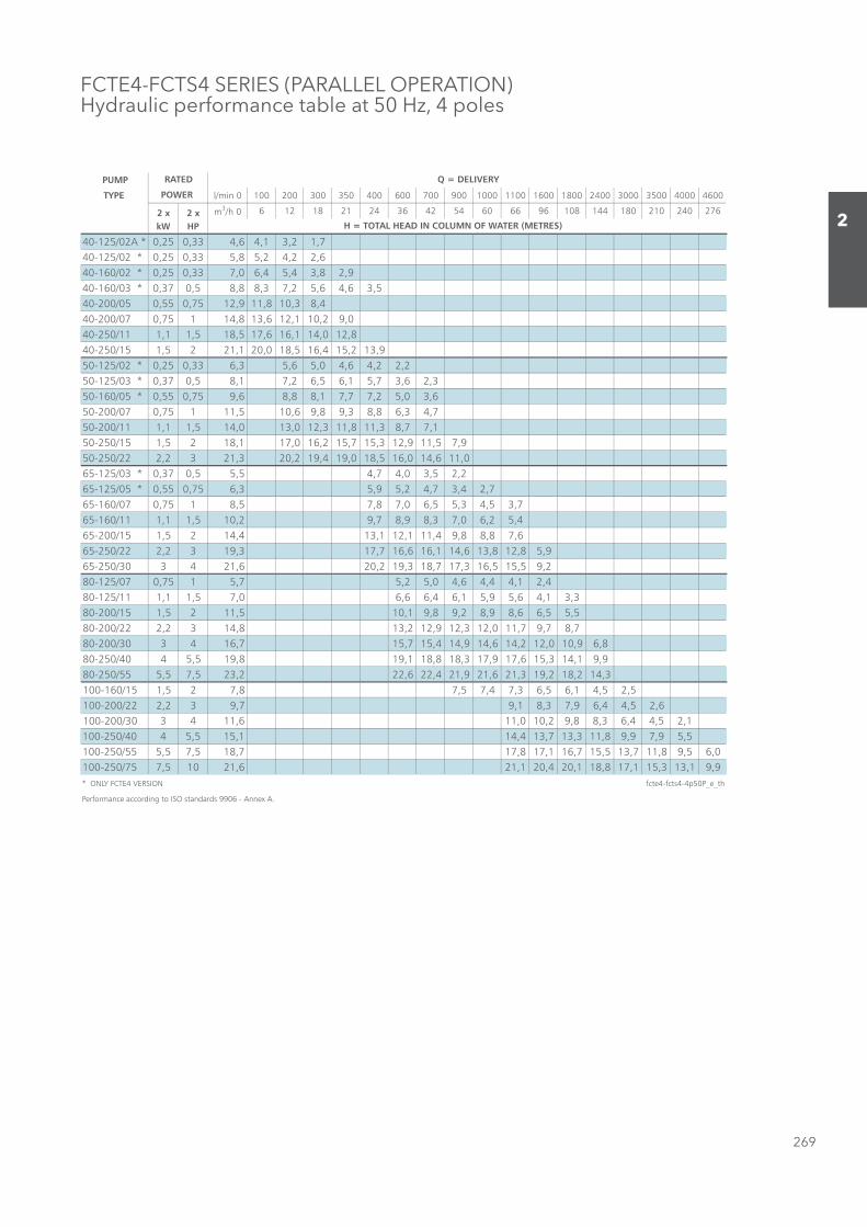
269
2
FCTE4-FCTS4 SERIES (PARALLEL OPERATION)Hydraulic performance table at 50 Hz, 4 poles
PUMP
TYPE l/min 0 100 200 300 350 400 600 700 900 1000 1100 1600 1800 2400 3000 3500 4000 4600
2 x 2 x m3/h 0 6 12 18 21 24 36 42 54 60 66 96 108 144 180 210 240 276
kW HP
40-125/02A * 0,25 0,33 4,6 4,1 3,2 1,740-125/02 * 0,25 0,33 5,8 5,2 4,2 2,640-160/02 * 0,25 0,33 7,0 6,4 5,4 3,8 2,940-160/03 * 0,37 0,5 8,8 8,3 7,2 5,6 4,6 3,540-200/05 0,55 0,75 12,9 11,8 10,3 8,440-200/07 0,75 1 14,8 13,6 12,1 10,2 9,040-250/11 1,1 1,5 18,5 17,6 16,1 14,0 12,840-250/15 1,5 2 21,1 20,0 18,5 16,4 15,2 13,950-125/02 * 0,25 0,33 6,3 5,6 5,0 4,6 4,2 2,250-125/03 * 0,37 0,5 8,1 7,2 6,5 6,1 5,7 3,6 2,350-160/05 * 0,55 0,75 9,6 8,8 8,1 7,7 7,2 5,0 3,650-200/07 0,75 1 11,5 10,6 9,8 9,3 8,8 6,3 4,750-200/11 1,1 1,5 14,0 13,0 12,3 11,8 11,3 8,7 7,150-250/15 1,5 2 18,1 17,0 16,2 15,7 15,3 12,9 11,5 7,950-250/22 2,2 3 21,3 20,2 19,4 19,0 18,5 16,0 14,6 11,065-125/03 * 0,37 0,5 5,5 4,7 4,0 3,5 2,265-125/05 * 0,55 0,75 6,3 5,9 5,2 4,7 3,4 2,765-160/07 0,75 1 8,5 7,8 7,0 6,5 5,3 4,5 3,765-160/11 1,1 1,5 10,2 9,7 8,9 8,3 7,0 6,2 5,465-200/15 1,5 2 14,4 13,1 12,1 11,4 9,8 8,8 7,665-250/22 2,2 3 19,3 17,7 16,6 16,1 14,6 13,8 12,8 5,965-250/30 3 4 21,6 20,2 19,3 18,7 17,3 16,5 15,5 9,280-125/07 0,75 1 5,7 5,2 5,0 4,6 4,4 4,1 2,480-125/11 1,1 1,5 7,0 6,6 6,4 6,1 5,9 5,6 4,1 3,380-200/15 1,5 2 11,5 10,1 9,8 9,2 8,9 8,6 6,5 5,580-200/22 2,2 3 14,8 13,2 12,9 12,3 12,0 11,7 9,7 8,780-200/30 3 4 16,7 15,7 15,4 14,9 14,6 14,2 12,0 10,9 6,880-250/40 4 5,5 19,8 19,1 18,8 18,3 17,9 17,6 15,3 14,1 9,980-250/55 5,5 7,5 23,2 22,6 22,4 21,9 21,6 21,3 19,2 18,2 14,3100-160/15 1,5 2 7,8 7,5 7,4 7,3 6,5 6,1 4,5 2,5100-200/22 2,2 3 9,7 9,1 8,3 7,9 6,4 4,5 2,6100-200/30 3 4 11,6 11,0 10,2 9,8 8,3 6,4 4,5 2,1100-250/40 4 5,5 15,1 14,4 13,7 13,3 11,8 9,9 7,9 5,5100-250/55 5,5 7,5 18,7 17,8 17,1 16,7 15,5 13,7 11,8 9,5 6,0100-250/75 7,5 10 21,6 21,1 20,4 20,1 18,8 17,1 15,3 13,1 9,9* ONLY FCTE4 VERSION fcte4-fcts4-4p50P_e_th
Performance according to ISO standards 9906 - Annex A.
RATED
POWER
Q = DELIVERY
H = TOTAL HEAD IN COLUMN OF WATER (METRES)
Sezione_02_uk.indd 269Sezione_02_uk.indd 269 07/03/12 16.1507/03/12 16.15
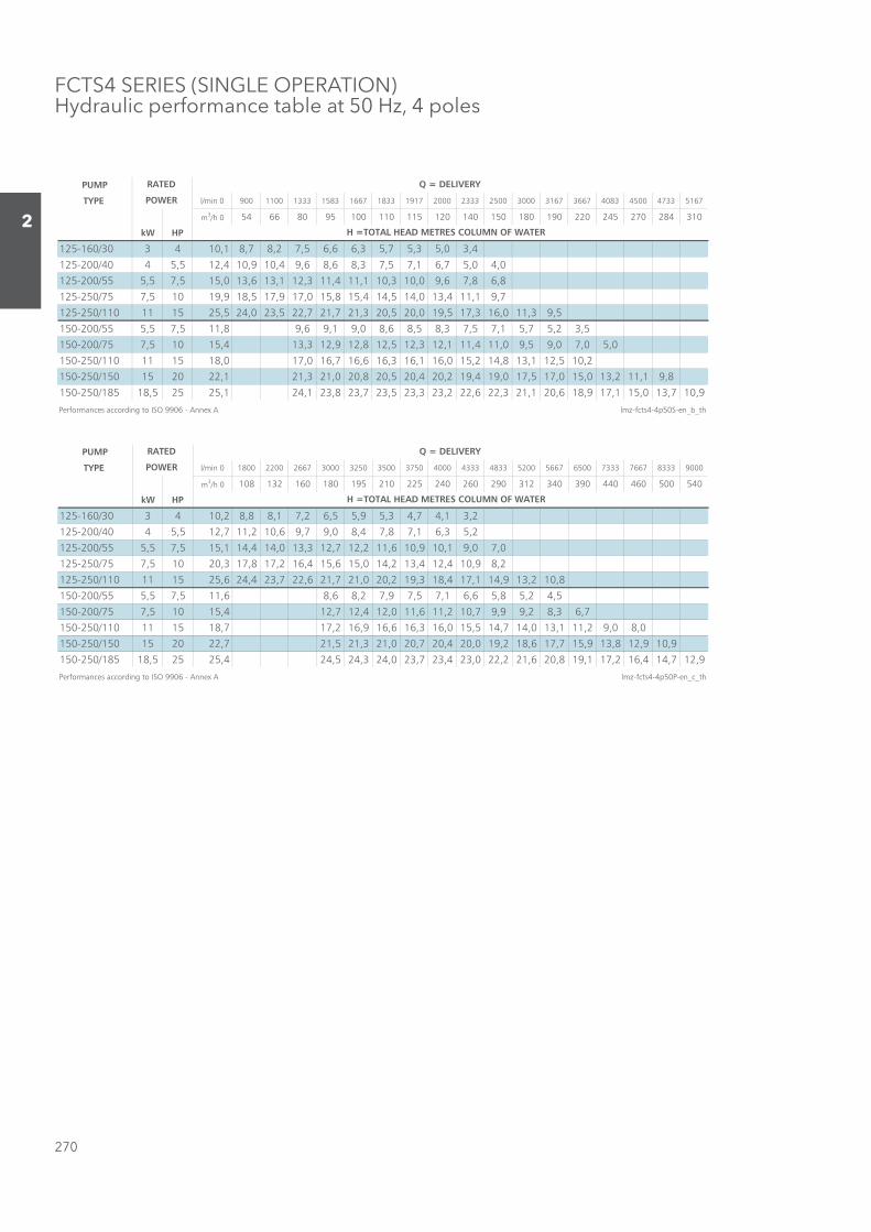
270
2
FCTS4 SERIES (SINGLE OPERATION)Hydraulic performance table at 50 Hz, 4 poles
PUMP
TYPE l/min 0 900 1100 1333 1583 1667 1833 1917 2000 2333 2500 3000 3167 3667 4083 4500 4733 5167
m3/h 0 54 66 80 95 100 110 115 120 140 150 180 190 220 245 270 284 310
kW HP
125-160/30 3 4 10,1 8,7 8,2 7,5 6,6 6,3 5,7 5,3 5,0 3,4
125-200/40 4 5,5 12,4 10,9 10,4 9,6 8,6 8,3 7,5 7,1 6,7 5,0 4,0
125-200/55 5,5 7,5 15,0 13,6 13,1 12,3 11,4 11,1 10,3 10,0 9,6 7,8 6,8
125-250/75 7,5 10 19,9 18,5 17,9 17,0 15,8 15,4 14,5 14,0 13,4 11,1 9,7
125-250/110 11 15 25,5 24,0 23,5 22,7 21,7 21,3 20,5 20,0 19,5 17,3 16,0 11,3 9,5
150-200/55 5,5 7,5 11,8 9,6 9,1 9,0 8,6 8,5 8,3 7,5 7,1 5,7 5,2 3,5
150-200/75 7,5 10 15,4 13,3 12,9 12,8 12,5 12,3 12,1 11,4 11,0 9,5 9,0 7,0 5,0
150-250/110 11 15 18,0 17,0 16,7 16,6 16,3 16,1 16,0 15,2 14,8 13,1 12,5 10,2
150-250/150 15 20 22,1 21,3 21,0 20,8 20,5 20,4 20,2 19,4 19,0 17,5 17,0 15,0 13,2 11,1 9,8
150-250/185 18,5 25 25,1 24,1 23,8 23,7 23,5 23,3 23,2 22,6 22,3 21,1 20,6 18,9 17,1 15,0 13,7 10,9
Performances according to ISO 9906 - Annex A lmz-fcts4-4p50S-en_b_th
RATED
POWER
Q = DELIVERY
H =TOTAL HEAD METRES COLUMN OF WATER
PUMP
TYPE l/min 0 1800 2200 2667 3000 3250 3500 3750 4000 4333 4833 5200 5667 6500 7333 7667 8333 9000
m3/h 0 108 132 160 180 195 210 225 240 260 290 312 340 390 440 460 500 540
kW HP
125-160/30 3 4 10,2 8,8 8,1 7,2 6,5 5,9 5,3 4,7 4,1 3,2
125-200/40 4 5,5 12,7 11,2 10,6 9,7 9,0 8,4 7,8 7,1 6,3 5,2
125-200/55 5,5 7,5 15,1 14,4 14,0 13,3 12,7 12,2 11,6 10,9 10,1 9,0 7,0
125-250/75 7,5 10 20,3 17,8 17,2 16,4 15,6 15,0 14,2 13,4 12,4 10,9 8,2
125-250/110 11 15 25,6 24,4 23,7 22,6 21,7 21,0 20,2 19,3 18,4 17,1 14,9 13,2 10,8
150-200/55 5,5 7,5 11,6 8,6 8,2 7,9 7,5 7,1 6,6 5,8 5,2 4,5
150-200/75 7,5 10 15,4 12,7 12,4 12,0 11,6 11,2 10,7 9,9 9,2 8,3 6,7
150-250/110 11 15 18,7 17,2 16,9 16,6 16,3 16,0 15,5 14,7 14,0 13,1 11,2 9,0 8,0
150-250/150 15 20 22,7 21,5 21,3 21,0 20,7 20,4 20,0 19,2 18,6 17,7 15,9 13,8 12,9 10,9
150-250/185 18,5 25 25,4 24,5 24,3 24,0 23,7 23,4 23,0 22,2 21,6 20,8 19,1 17,2 16,4 14,7 12,9
Performances according to ISO 9906 - Annex A lmz-fcts4-4p50P-en_c_th
RATED
POWER
Q = DELIVERY
H =TOTAL HEAD METRES COLUMN OF WATER
Sezione_02_uk.indd 270Sezione_02_uk.indd 270 07/03/12 16.1507/03/12 16.15

271
2
FCTE-FCTS SERIESOperating characteristics at 50 Hz, 2 poles
These NPSH values are valid in laboratory conditions; for practical purposes, values should be increased by a 0.5 m safety margin.
These performances are valid for liquids with density ρ = 1.0 kg/dm3 and kinematic viscosity ν = 1 mm2/s.
Sezione_02_uk.indd 271Sezione_02_uk.indd 271 07/03/12 16.1507/03/12 16.15
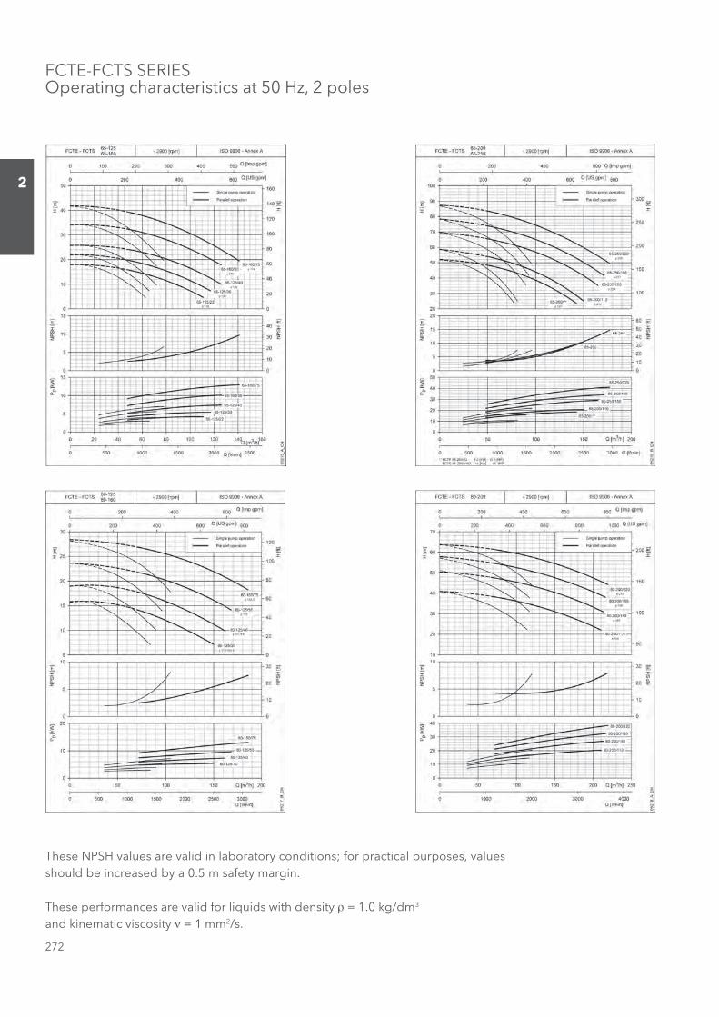
272
2
FCTE-FCTS SERIESOperating characteristics at 50 Hz, 2 poles
These NPSH values are valid in laboratory conditions; for practical purposes, values should be increased by a 0.5 m safety margin.
These performances are valid for liquids with density ρ = 1.0 kg/dm3 and kinematic viscosity ν = 1 mm2/s.
Sezione_02_uk.indd 272Sezione_02_uk.indd 272 07/03/12 16.1507/03/12 16.15
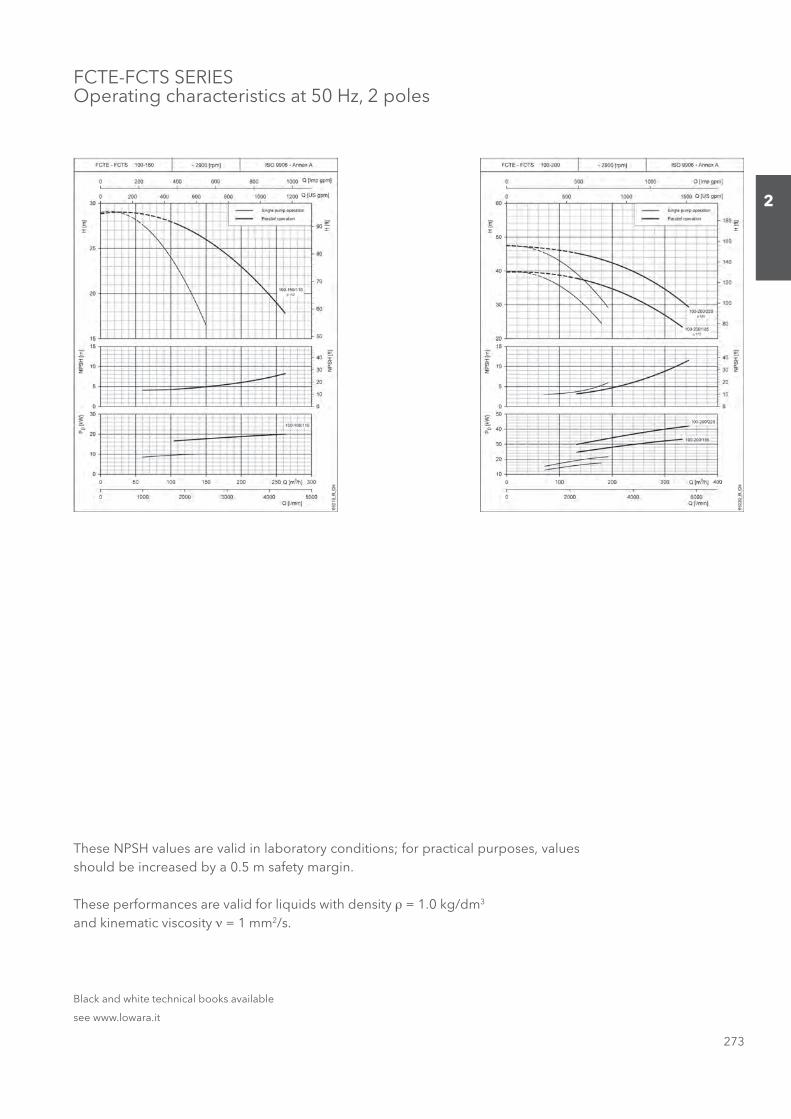
273
2
FCTE-FCTS SERIESOperating characteristics at 50 Hz, 2 poles
These NPSH values are valid in laboratory conditions; for practical purposes, values should be increased by a 0.5 m safety margin.
These performances are valid for liquids with density ρ = 1.0 kg/dm3 and kinematic viscosity ν = 1 mm2/s.
Black and white technical books available
see www.lowara.it
Sezione_02_uk.indd 273Sezione_02_uk.indd 273 07/03/12 16.1507/03/12 16.15
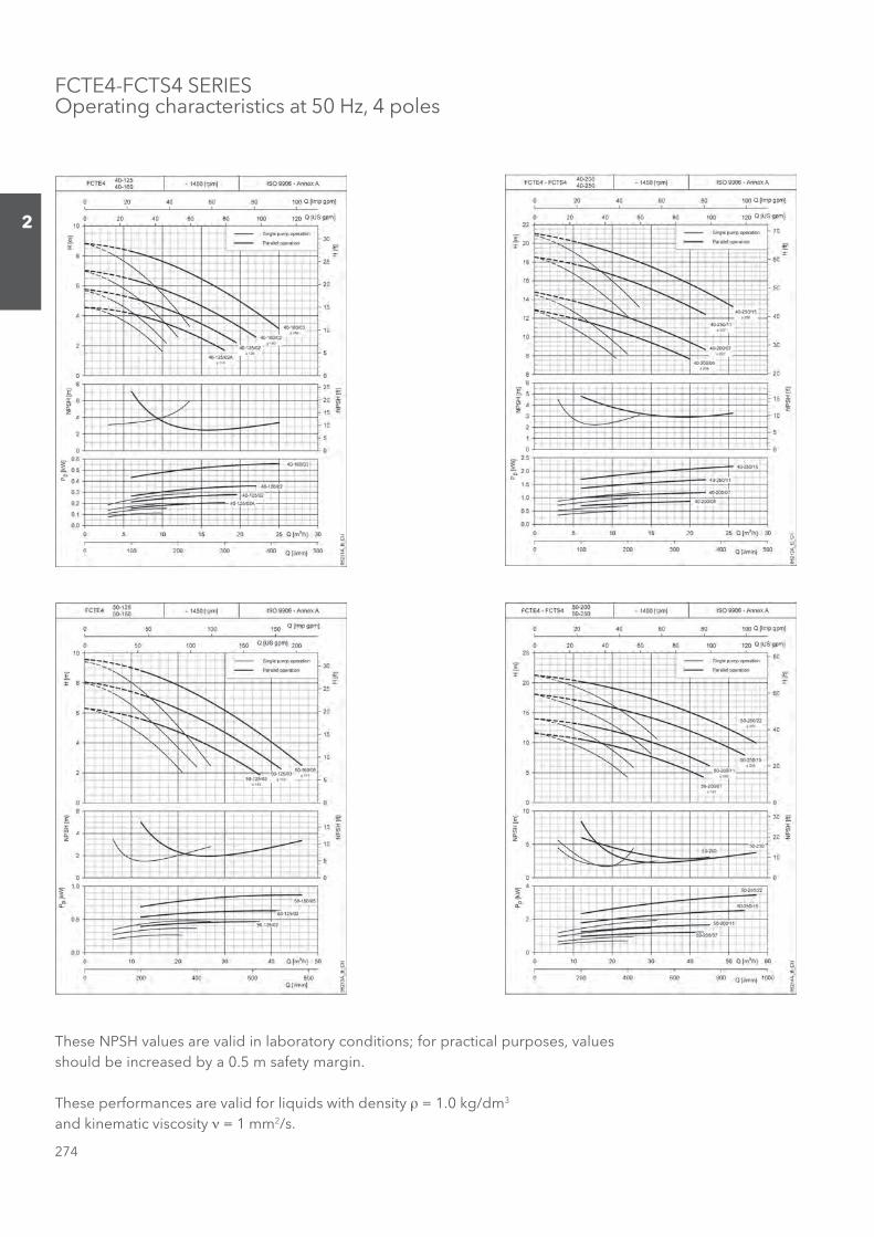
274
2
These NPSH values are valid in laboratory conditions; for practical purposes, values should be increased by a 0.5 m safety margin.
These performances are valid for liquids with density ρ = 1.0 kg/dm3 and kinematic viscosity ν = 1 mm2/s.
FCTE4-FCTS4 SERIESOperating characteristics at 50 Hz, 4 poles
Sezione_02_uk.indd 274Sezione_02_uk.indd 274 07/03/12 16.1507/03/12 16.15

275
2
FCTE4-FCTS4 SERIESOperating characteristics at 50 Hz, 4 poles
These NPSH values are valid in laboratory conditions; for practical purposes, values should be increased by a 0.5 m safety margin.
These performances are valid for liquids with density ρ = 1.0 kg/dm3 and kinematic viscosity ν = 1 mm2/s.
Sezione_02_uk.indd 275Sezione_02_uk.indd 275 07/03/12 16.1507/03/12 16.15
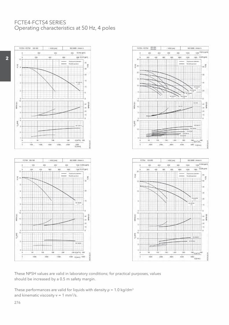
276
2
These NPSH values are valid in laboratory conditions; for practical purposes, values should be increased by a 0.5 m safety margin.
These performances are valid for liquids with density ρ = 1.0 kg/dm3 and kinematic viscosity ν = 1 mm2/s.
FCTE4-FCTS4 SERIESOperating characteristics at 50 Hz, 4 poles
Sezione_02_uk.indd 276Sezione_02_uk.indd 276 07/03/12 16.1507/03/12 16.15
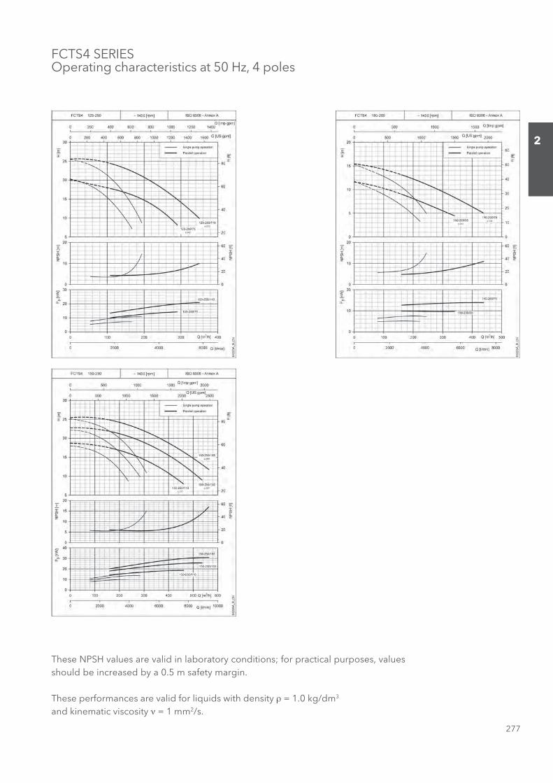
277
2
FCTS4 SERIESOperating characteristics at 50 Hz, 4 poles
These NPSH values are valid in laboratory conditions; for practical purposes, values should be increased by a 0.5 m safety margin.
These performances are valid for liquids with density ρ = 1.0 kg/dm3 and kinematic viscosity ν = 1 mm2/s.
Sezione_02_uk.indd 277Sezione_02_uk.indd 277 07/03/12 16.1507/03/12 16.15
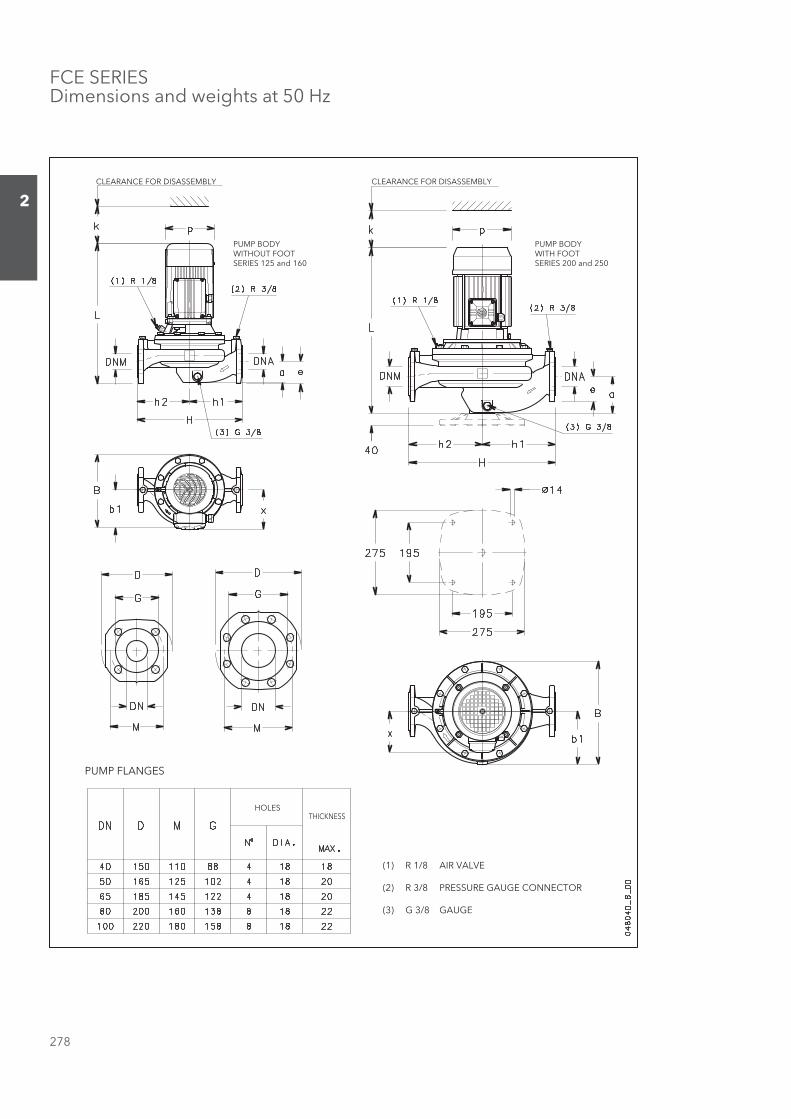
278
2
FCE SERIES Dimensions and weights at 50 Hz
CLEARANCE FOR DISASSEMBLY
PUMP BODYWITHOUT FOOTSERIES 125 and 160
CLEARANCE FOR DISASSEMBLY
PUMP BODYWITH FOOTSERIES 200 and 250
PUMP FLANGES
HOLESTHICKNESS
(1) R 1/8 AIR VALVE
(2) R 3/8 PRESSURE GAUGE CONNECTOR
(3) G 3/8 GAUGE
Sezione_02_uk.indd 278Sezione_02_uk.indd 278 07/03/12 16.1507/03/12 16.15
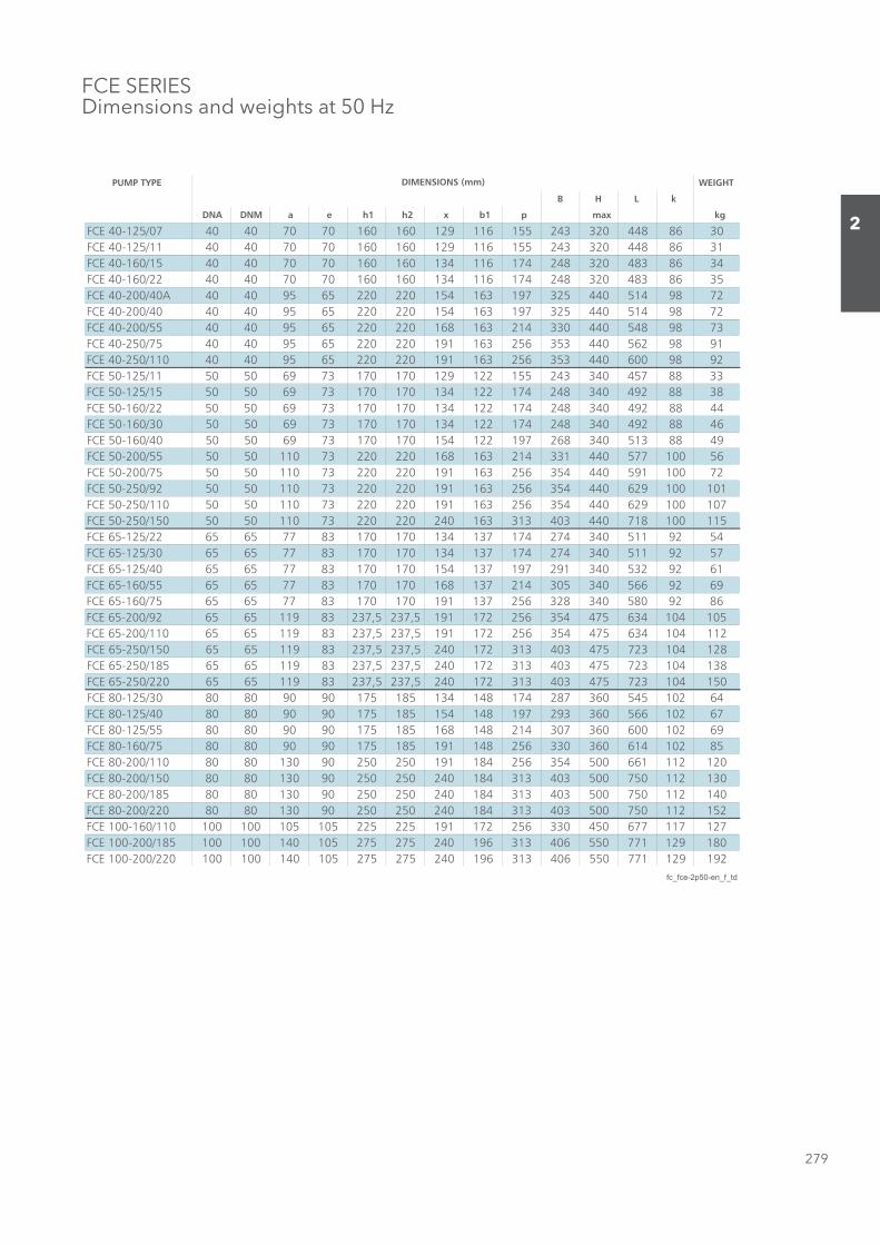
279
2
FCE SERIES Dimensions and weights at 50 Hz
PUMP TYPE WEIGHT
B H L k
DNA DNM a e h1 h2 x b1 p max kg
FCE 40-125/07 40 40 70 70 160 160 129 116 155 243 320 448 86 30FCE 40-125/11 40 40 70 70 160 160 129 116 155 243 320 448 86 31FCE 40-160/15 40 40 70 70 160 160 134 116 174 248 320 483 86 34FCE 40-160/22 40 40 70 70 160 160 134 116 174 248 320 483 86 35FCE 40-200/40A 40 40 95 65 220 220 154 163 197 325 440 514 98 72FCE 40-200/40 40 40 95 65 220 220 154 163 197 325 440 514 98 72FCE 40-200/55 40 40 95 65 220 220 168 163 214 330 440 548 98 73FCE 40-250/75 40 40 95 65 220 220 191 163 256 353 440 562 98 91FCE 40-250/110 40 40 95 65 220 220 191 163 256 353 440 600 98 92FCE 50-125/11 50 50 69 73 170 170 129 122 155 243 340 457 88 33FCE 50-125/15 50 50 69 73 170 170 134 122 174 248 340 492 88 38FCE 50-160/22 50 50 69 73 170 170 134 122 174 248 340 492 88 44FCE 50-160/30 50 50 69 73 170 170 134 122 174 248 340 492 88 46FCE 50-160/40 50 50 69 73 170 170 154 122 197 268 340 513 88 49FCE 50-200/55 50 50 110 73 220 220 168 163 214 331 440 577 100 56FCE 50-200/75 50 50 110 73 220 220 191 163 256 354 440 591 100 72FCE 50-250/92 50 50 110 73 220 220 191 163 256 354 440 629 100 101FCE 50-250/110 50 50 110 73 220 220 191 163 256 354 440 629 100 107FCE 50-250/150 50 50 110 73 220 220 240 163 313 403 440 718 100 115FCE 65-125/22 65 65 77 83 170 170 134 137 174 274 340 511 92 54FCE 65-125/30 65 65 77 83 170 170 134 137 174 274 340 511 92 57FCE 65-125/40 65 65 77 83 170 170 154 137 197 291 340 532 92 61FCE 65-160/55 65 65 77 83 170 170 168 137 214 305 340 566 92 69FCE 65-160/75 65 65 77 83 170 170 191 137 256 328 340 580 92 86FCE 65-200/92 65 65 119 83 237,5 237,5 191 172 256 354 475 634 104 105FCE 65-200/110 65 65 119 83 237,5 237,5 191 172 256 354 475 634 104 112FCE 65-250/150 65 65 119 83 237,5 237,5 240 172 313 403 475 723 104 128FCE 65-250/185 65 65 119 83 237,5 237,5 240 172 313 403 475 723 104 138FCE 65-250/220 65 65 119 83 237,5 237,5 240 172 313 403 475 723 104 150FCE 80-125/30 80 80 90 90 175 185 134 148 174 287 360 545 102 64FCE 80-125/40 80 80 90 90 175 185 154 148 197 293 360 566 102 67FCE 80-125/55 80 80 90 90 175 185 168 148 214 307 360 600 102 69FCE 80-160/75 80 80 90 90 175 185 191 148 256 330 360 614 102 85FCE 80-200/110 80 80 130 90 250 250 191 184 256 354 500 661 112 120FCE 80-200/150 80 80 130 90 250 250 240 184 313 403 500 750 112 130FCE 80-200/185 80 80 130 90 250 250 240 184 313 403 500 750 112 140FCE 80-200/220 80 80 130 90 250 250 240 184 313 403 500 750 112 152FCE 100-160/110 100 100 105 105 225 225 191 172 256 330 450 677 117 127FCE 100-200/185 100 100 140 105 275 275 240 196 313 406 550 771 129 180FCE 100-200/220 100 100 140 105 275 275 240 196 313 406 550 771 129 192
fc_fce-2p50-en_f_td
DIMENSIONS (mm)
Sezione_02_uk.indd 279Sezione_02_uk.indd 279 07/03/12 16.1507/03/12 16.15

280
2
FCE4 SERIES Dimensions and weights at 50 Hz
CLEARANCE FOR DISASSEMBLY
PUMP BODYWITHOUT FOOTSERIES 125 and 160
CLEARANCE FOR DISASSEMBLY
PUMP BODYWITH FOOTSERIES 200 and 250
PUMP FLANGES
HOLESTHICKNESS
(1) R 1/8 AIR VALVE
(2) R 3/8 PRESSURE GAUGE CONNECTOR
(3) G 3/8 GAUGE
Sezione_02_uk.indd 280Sezione_02_uk.indd 280 07/03/12 16.1507/03/12 16.15
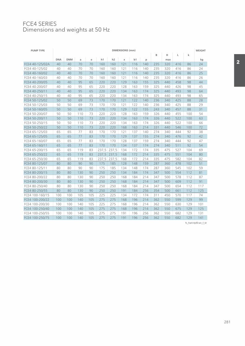
281
2
FCE4 SERIES Dimensions and weights at 50 Hz
PUMP TYPE WEIGHT
B H L k
DNA DNM a e h1 h2 x b1 p max kg
FCE4 40-125/02A 40 40 70 70 160 160 121 116 140 235 320 416 86 24FCE4 40-125/02 40 40 70 70 160 160 121 116 140 235 320 416 86 24FCE4 40-160/02 40 40 70 70 160 160 121 116 140 235 320 416 86 25FCE4 40-160/03 40 40 70 70 160 160 121 116 140 235 320 416 86 26FCE4 40-200/05 40 40 95 65 220 220 129 163 155 325 440 458 98 44FCE4 40-200/07 40 40 95 65 220 220 128 163 159 325 440 426 98 45FCE4 40-250/11 40 40 95 65 220 220 134 163 174 325 440 493 98 64FCE4 40-250/15 40 40 95 65 220 220 134 163 174 325 440 493 98 65FCE4 50-125/02 50 50 69 73 170 170 121 122 140 236 340 425 88 28FCE4 50-125/03 50 50 69 73 170 170 121 122 140 236 340 425 88 29FCE4 50-160/05 50 50 69 73 170 170 129 122 155 243 340 457 88 31FCE4 50-200/07 50 50 110 73 220 220 128 163 159 326 440 455 100 54FCE4 50-200/11 50 50 110 73 220 220 134 163 174 326 440 522 100 63FCE4 50-250/15 50 50 110 73 220 220 134 163 174 326 440 522 100 66FCE4 50-250/22 50 50 110 73 220 220 168 163 214 331 440 546 100 72FCE4 65-125/03 65 65 77 83 170 170 121 137 140 274 340 444 92 38FCE4 65-125/05 65 65 77 83 170 170 129 137 155 274 340 476 92 42FCE4 65-160/07 65 65 77 83 170 170 128 137 159 274 340 444 92 47FCE4 65-160/11 65 65 77 83 170 170 134 137 174 274 340 511 92 54FCE4 65-200/15 65 65 119 83 237,5 237,5 134 172 174 335 475 527 104 69FCE4 65-250/22 65 65 119 83 237,5 237,5 168 172 214 335 475 551 104 80FCE4 65-250/30 65 65 119 83 237,5 237,5 168 172 214 335 475 582 104 82FCE4 80-125/07 80 80 90 90 175 185 128 148 159 287 360 478 102 51FCE4 80-125/11 80 80 90 90 175 185 134 148 174 287 360 545 102 59FCE4 80-200/15 80 80 130 90 250 250 134 184 174 347 500 554 112 81FCE4 80-200/22 80 80 130 90 250 250 168 184 214 347 500 578 112 87FCE4 80-200/30 80 80 130 90 250 250 168 184 214 347 500 609 112 91FCE4 80-250/40 80 80 130 90 250 250 168 184 214 347 500 654 112 117FCE4 80-250/55 80 80 130 90 250 250 191 184 256 354 500 661 112 125FCE4 100-160/15 100 100 105 105 225 225 134 172 174 311 450 570 117 74FCE4 100-200/22 100 100 140 105 275 275 168 196 214 362 550 599 129 99FCE4 100-200/30 100 100 140 105 225 275 168 196 214 362 550 630 129 101FCE4 100-250/40 100 100 140 105 275 275 168 196 214 362 550 675 129 125FCE4 100-250/55 100 100 140 105 275 275 191 196 256 362 550 682 129 131FCE4 100-250/75 100 100 140 105 275 275 191 196 256 362 550 682 129 141
fc_fce4-4p50-en_f_td
DIMENSIONS (mm)
Sezione_02_uk.indd 281Sezione_02_uk.indd 281 07/03/12 16.1507/03/12 16.15
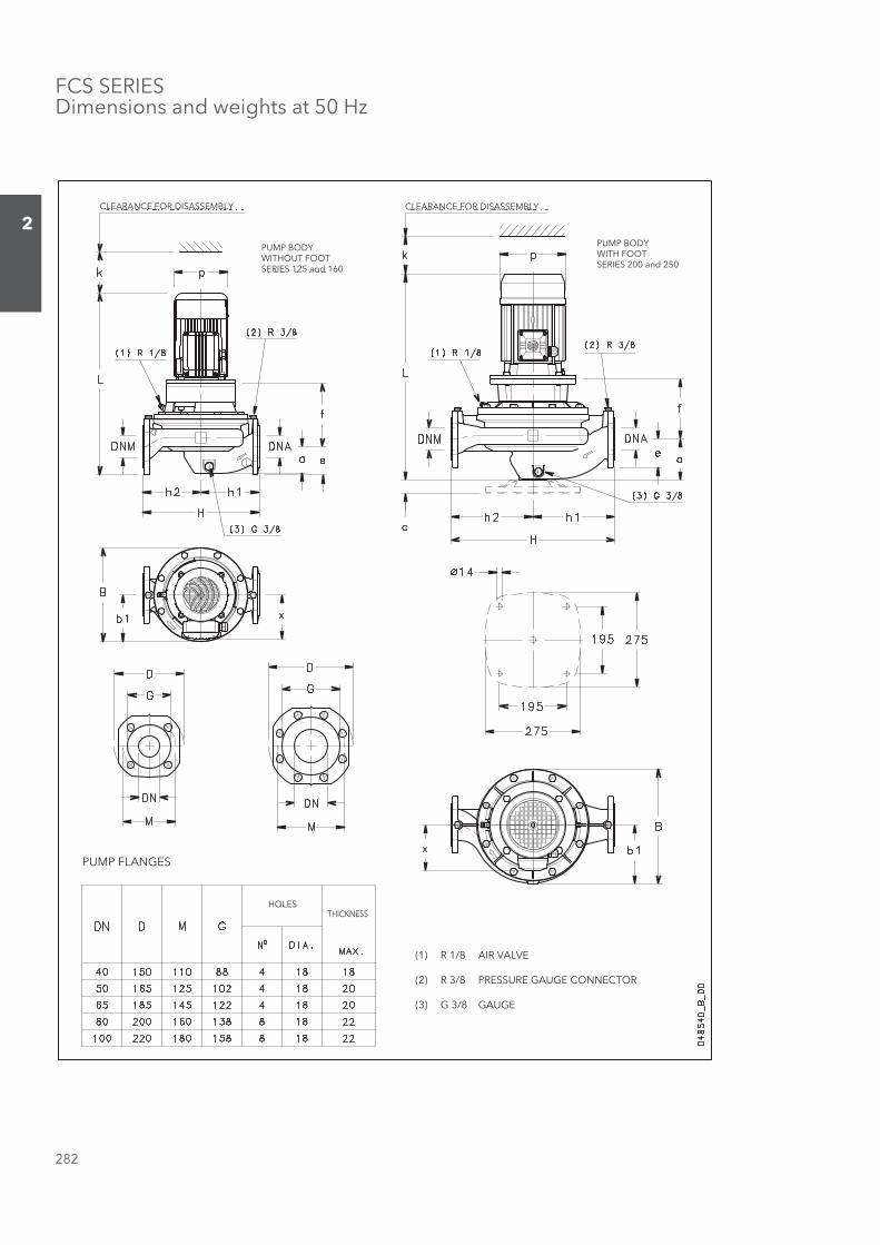
282
2
FCS SERIES Dimensions and weights at 50 Hz
CLEARANCE FOR DISASSEMBLY
PUMP BODYWITHOUT FOOTSERIES 125 and 160
CLEARANCE FOR DISASSEMBLY
PUMP BODYWITH FOOTSERIES 200 and 250
PUMP FLANGES
HOLESTHICKNESS
(1) R 1/8 AIR VALVE
(2) R 3/8 PRESSURE GAUGE CONNECTOR
(3) G 3/8 GAUGE
Sezione_02_uk.indd 282Sezione_02_uk.indd 282 07/03/12 16.1507/03/12 16.15

283
2
FCS SERIES Dimensions and weights at 50 Hz
PUMP TYPE WEIGHT
B H L k
DNA DNM a e f h1 h2 x b1 p max kg
FCS 40-125/07 40 40 70 70 170 160 160 129 116 155 243 320 503 86 33FCS 40-125/11 40 40 70 70 170 160 160 129 116 155 243 320 503 86 34FCS 40-160/15 40 40 70 70 170 160 160 134 116 174 248 320 538 86 37FCS 40-160/22 40 40 70 70 170 160 160 134 116 174 248 320 538 86 39FCS 40-200/30 40 40 95 65 165 220 220 134 163 174 325 440 558 98 69FCS 40-200/40 40 40 95 65 165 220 220 154 163 197 325 440 579 98 75FCS 40-200/55 40 40 95 65 192 220 220 168 163 214 330 440 662 98 88FCS 40-250/75 40 40 95 65 192 220 220 191 163 256 353 440 654 98 106FCS 40-250/110 40 40 95 65 222 220 220 191 163 256 353 440 745 98 120FCS 50-125/11 50 50 69 73 176 170 170 129 122 155 243 340 512 88 38FCS 50-125/15 50 50 69 73 176 170 170 134 122 174 248 340 547 88 42FCS 50-160/22 50 50 69 73 176 170 170 134 122 174 248 340 547 88 50FCS 50-160/30 50 50 69 73 186 170 170 134 122 174 248 340 557 88 51FCS 50-160/40 50 50 69 73 186 170 170 154 122 197 268 340 578 88 58FCS50-200/55 50 50 110 73 206 220 220 168 163 214 331 440 691 100 91FCS 50-200/75 50 50 110 73 206 220 220 191 163 256 354 440 683 100 108FCS 50-250/110A 50 50 110 73 236 220 220 191 163 256 354 440 774 100 115FCS 50-250/110 50 50 110 73 236 220 220 191 163 256 354 440 774 100 115FCS 50-250/150 50 50 110 73 236 220 220 240 163 313 403 440 840 100 125FCS 65-125/22 65 65 77 83 185 170 170 134 137 174 274 340 566 92 69FCS 65-125/30 65 65 77 83 195 170 170 134 137 174 274 340 576 92 62FCS 65-125/40 65 65 77 83 195 170 170 154 137 197 291 340 597 92 67FCS 65-160/55 65 65 77 83 222 170 170 168 137 214 305 340 680 92 80FCS 65-160/75 65 65 77 83 222 170 170 191 137 256 328 340 672 92 95FCS 65-200/110A 65 65 119 83 232 237,5 237,5 191 172 256 354 475 779 104 133FCS 65-200/110 65 65 119 83 232 237,5 237,5 191 172 256 354 475 779 104 133FCS 65-250/150 65 65 119 83 232 237,5 237,5 240 172 313 403 475 845 104 134FCS 65-250/185 65 65 119 83 232 237,5 237,5 240 172 313 403 475 845 104 144FCS 65-250/220 65 65 119 83 232 237,5 237,5 240 172 313 403 475 845 104 154FCS 80-125/30 80 80 90 90 222 175 185 134 148 174 287 360 610 102 82FCS 80-125/40 80 80 90 90 222 175 185 154 148 197 293 360 631 102 83FCS 80-125/55 80 80 90 90 249 175 185 168 148 214 307 360 714 102 86FCS 80-160/75 80 80 90 90 249 175 185 191 148 256 330 360 706 102 102FCS 80-200/110 80 80 130 90 248 250 250 191 184 256 354 500 806 112 130FCS 80-200/150 80 80 130 90 248 250 250 240 184 313 403 500 872 112 140FCS 80-200/185 80 80 130 90 248 250 250 240 184 313 403 500 872 112 150FCS 80-200/220 80 80 130 90 248 250 250 240 184 313 403 500 872 112 162FCS 100-160/110 100 100 105 105 289 225 225 191 172 256 330 450 822 117 135FCS 100-200/185 100 100 140 105 259 275 275 240 196 313 406 550 893 129 190FCS 100-200/220 100 100 140 105 259 275 275 240 196 313 406 550 893 129 202
fc_fcs-2p50-en_f_td
DIMENSIONS (mm)
Sezione_02_uk.indd 283Sezione_02_uk.indd 283 07/03/12 16.1507/03/12 16.15
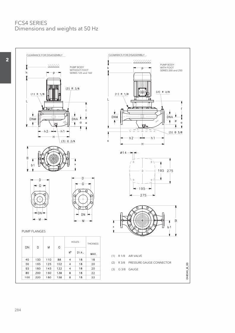
284
2
FCS4 SERIES Dimensions and weights at 50 Hz
CLEARANCE FOR DISASSEMBLY
PUMP BODYWITHOUT FOOTSERIES 125 and 160
CLEARANCE FOR DISASSEMBLY
PUMP BODYWITH FOOTSERIES 200 and 250
PUMP FLANGES
HOLESTHICKNESS
(1) R 1/8 AIR VALVE
(2) R 3/8 PRESSURE GAUGE CONNECTOR
(3) G 3/8 GAUGE
Sezione_02_uk.indd 284Sezione_02_uk.indd 284 07/03/12 16.1507/03/12 16.15
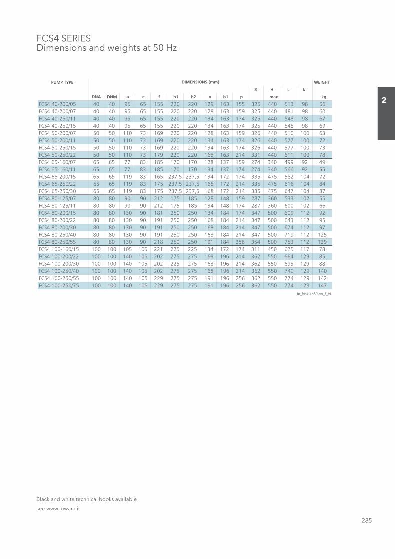
285
2
FCS4 SERIES Dimensions and weights at 50 Hz
PUMP TYPE WEIGHT
B H L k
DNA DNM a e f h1 h2 x b1 p max kg
FCS4 40-200/05 40 40 95 65 155 220 220 129 163 155 325 440 513 98 56FCS4 40-200/07 40 40 95 65 155 220 220 128 163 159 325 440 481 98 60FCS4 40-250/11 40 40 95 65 155 220 220 134 163 174 325 440 548 98 67FCS4 40-250/15 40 40 95 65 155 220 220 134 163 174 325 440 548 98 69FCS4 50-200/07 50 50 110 73 169 220 220 128 163 159 326 440 510 100 63FCS4 50-200/11 50 50 110 73 169 220 220 134 163 174 326 440 577 100 72FCS4 50-250/15 50 50 110 73 169 220 220 134 163 174 326 440 577 100 73FCS4 50-250/22 50 50 110 73 179 220 220 168 163 214 331 440 611 100 78FCS4 65-160/07 65 65 77 83 185 170 170 128 137 159 274 340 499 92 49FCS4 65-160/11 65 65 77 83 185 170 170 134 137 174 274 340 566 92 55FCS4 65-200/15 65 65 119 83 165 237,5 237,5 134 172 174 335 475 582 104 72FCS4 65-250/22 65 65 119 83 175 237,5 237,5 168 172 214 335 475 616 104 84FCS4 65-250/30 65 65 119 83 175 237,5 237,5 168 172 214 335 475 647 104 87FCS4 80-125/07 80 80 90 90 212 175 185 128 148 159 287 360 533 102 55FCS4 80-125/11 80 80 90 90 212 175 185 134 148 174 287 360 600 102 66FCS4 80-200/15 80 80 130 90 181 250 250 134 184 174 347 500 609 112 92FCS4 80-200/22 80 80 130 90 191 250 250 168 184 214 347 500 643 112 95FCS4 80-200/30 80 80 130 90 191 250 250 168 184 214 347 500 674 112 97FCS4 80-250/40 80 80 130 90 191 250 250 168 184 214 347 500 719 112 125FCS4 80-250/55 80 80 130 90 218 250 250 191 184 256 354 500 753 112 129FCS4 100-160/15 100 100 105 105 221 225 225 134 172 174 311 450 625 117 78FCS4 100-200/22 100 100 140 105 202 275 275 168 196 214 362 550 664 129 85FCS4 100-200/30 100 100 140 105 202 225 275 168 196 214 362 550 695 129 88FCS4 100-250/40 100 100 140 105 202 275 275 168 196 214 362 550 740 129 140FCS4 100-250/55 100 100 140 105 229 275 275 191 196 256 362 550 774 129 142FCS4 100-250/75 100 100 140 105 229 275 275 191 196 256 362 550 774 129 147
fc_fcs4-4p50-en_f_td
DIMENSIONS (mm)
Black and white technical books available
see www.lowara.it
Sezione_02_uk.indd 285Sezione_02_uk.indd 285 07/03/12 16.1507/03/12 16.15
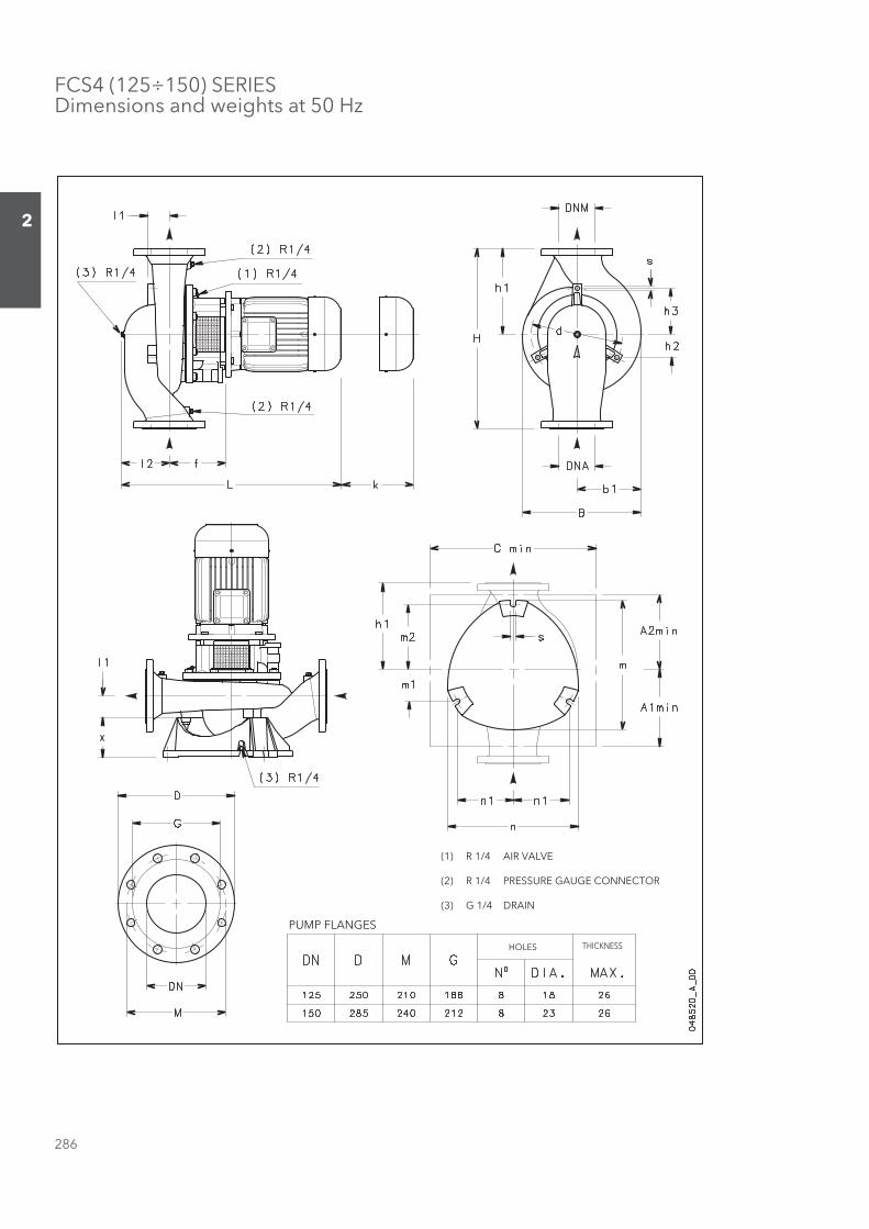
286
2
FCS4 (125÷150) SERIESDimensions and weights at 50 Hz
PUMP FLANGES
HOLES THICKNESS
(1) R 1/4 AIR VALVE
(2) R 1/4 PRESSURE GAUGE CONNECTOR
(3) G 1/4 DRAIN
Sezione_02_uk.indd 286Sezione_02_uk.indd 286 07/03/12 16.1507/03/12 16.15
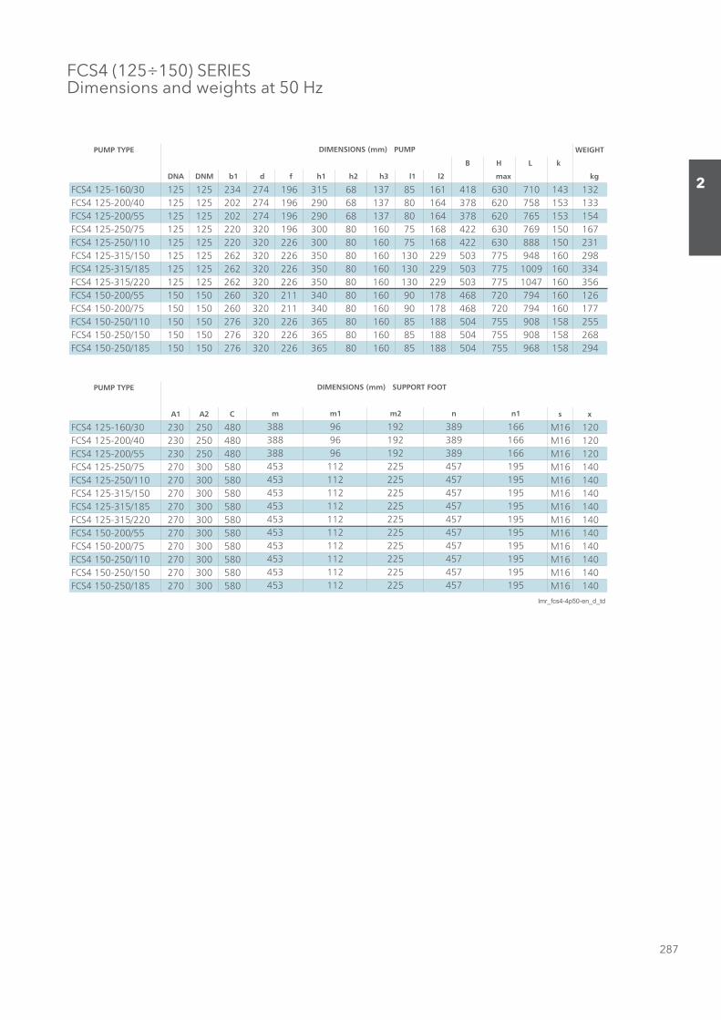
287
2
FCS4 (125÷150) SERIESDimensions and weights at 50 Hz
PUMP TYPE WEIGHT
B H L k
DNA DNM b1 d f h1 h2 h3 l1 l2 max kg
FCS4 125-160/30 125 125 234 274 196 315 68 137 85 161 418 630 710 143 132FCS4 125-200/40 125 125 202 274 196 290 68 137 80 164 378 620 758 153 133FCS4 125-200/55 125 125 202 274 196 290 68 137 80 164 378 620 765 153 154FCS4 125-250/75 125 125 220 320 196 300 80 160 75 168 422 630 769 150 167FCS4 125-250/110 125 125 220 320 226 300 80 160 75 168 422 630 888 150 231FCS4 125-315/150 125 125 262 320 226 350 80 160 130 229 503 775 948 160 298FCS4 125-315/185 125 125 262 320 226 350 80 160 130 229 503 775 1009 160 334FCS4 125-315/220 125 125 262 320 226 350 80 160 130 229 503 775 1047 160 356FCS4 150-200/55 150 150 260 320 211 340 80 160 90 178 468 720 794 160 126FCS4 150-200/75 150 150 260 320 211 340 80 160 90 178 468 720 794 160 177FCS4 150-250/110 150 150 276 320 226 365 80 160 85 188 504 755 908 158 255FCS4 150-250/150 150 150 276 320 226 365 80 160 85 188 504 755 908 158 268FCS4 150-250/185 150 150 276 320 226 365 80 160 85 188 504 755 968 158 294
PUMP TYPE
A1 A2 C s x
02161M08405203203/061-521 4SCF02161M08405203204/002-521 4SCF02161M08405203255/002-521 4SCF04161M08500307257/052-521 4SCF04161M085003072011/052-521 4SCF04161M085003072051/513-521 4SCF04161M085003072581/513-521 4SCF04161M085003072022/513-521 4SCF04161M08500307255/002-051 4SCF04161M08500307257/002-051 4SCF04161M085003072011/052-051 4SCF04161M085003072051/052-051 4SCF04161M085003072581/052-051 4SCF
lmr_fcs4-4p50-en_d_td
195
195195195
195195195
457457457
n1
166166166195195195
457457457457
225225225
n
389389389457457457
225225225225
112112112
m2
192192192225225225
112112112112
453453453
m1
969696112112112
453453
453
453453
DIMENSIONS (mm) PUMP
DIMENSIONS (mm) SUPPORT FOOT
453453
m
388388388
Sezione_02_uk.indd 287Sezione_02_uk.indd 287 07/03/12 16.1507/03/12 16.15

288
2
FCTE SERIES Dimensions and weights at 50 Hz
Sezione_02_uk.indd 288Sezione_02_uk.indd 288 07/03/12 16.1507/03/12 16.15
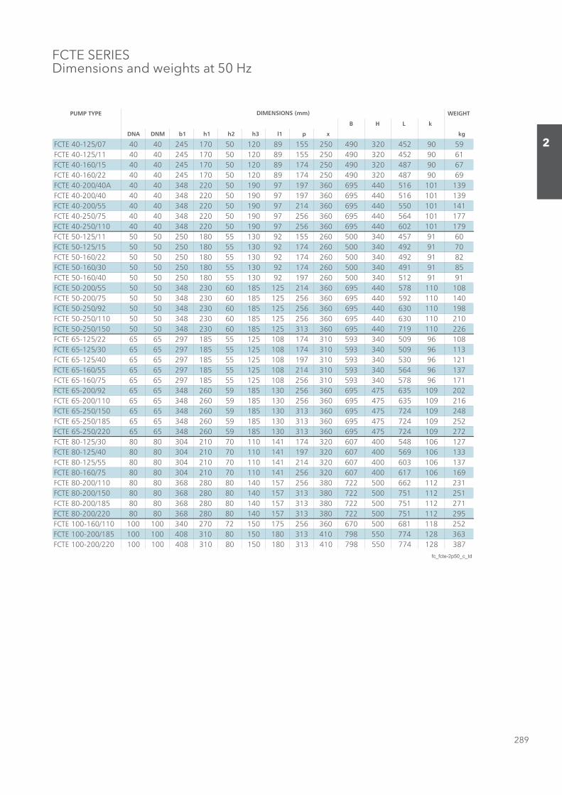
289
2
FCTE SERIES Dimensions and weights at 50 Hz
PUMP TYPE WEIGHT
B H L k
DNA DNM b1 h1 h2 h3 l1 p x kg
FCTE 40-125/07 40 40 245 170 50 120 89 155 250 490 320 452 90 59FCTE 40-125/11 40 40 245 170 50 120 89 155 250 490 320 452 90 61FCTE 40-160/15 40 40 245 170 50 120 89 174 250 490 320 487 90 67FCTE 40-160/22 40 40 245 170 50 120 89 174 250 490 320 487 90 69FCTE 40-200/40A 40 40 348 220 50 190 97 197 360 695 440 516 101 139FCTE 40-200/40 40 40 348 220 50 190 97 197 360 695 440 516 101 139FCTE 40-200/55 40 40 348 220 50 190 97 214 360 695 440 550 101 141FCTE 40-250/75 40 40 348 220 50 190 97 256 360 695 440 564 101 177FCTE 40-250/110 40 40 348 220 50 190 97 256 360 695 440 602 101 179FCTE 50-125/11 50 50 250 180 55 130 92 155 260 500 340 457 91 60FCTE 50-125/15 50 50 250 180 55 130 92 174 260 500 340 492 91 70FCTE 50-160/22 50 50 250 180 55 130 92 174 260 500 340 492 91 82FCTE 50-160/30 50 50 250 180 55 130 92 174 260 500 340 491 91 85FCTE 50-160/40 50 50 250 180 55 130 92 197 260 500 340 512 91 91FCTE 50-200/55 50 50 348 230 60 185 125 214 360 695 440 578 110 108FCTE 50-200/75 50 50 348 230 60 185 125 256 360 695 440 592 110 140FCTE 50-250/92 50 50 348 230 60 185 125 256 360 695 440 630 110 198FCTE 50-250/110 50 50 348 230 60 185 125 256 360 695 440 630 110 210FCTE 50-250/150 50 50 348 230 60 185 125 313 360 695 440 719 110 226FCTE 65-125/22 65 65 297 185 55 125 108 174 310 593 340 509 96 108FCTE 65-125/30 65 65 297 185 55 125 108 174 310 593 340 509 96 113FCTE 65-125/40 65 65 297 185 55 125 108 197 310 593 340 530 96 121FCTE 65-160/55 65 65 297 185 55 125 108 214 310 593 340 564 96 137FCTE 65-160/75 65 65 297 185 55 125 108 256 310 593 340 578 96 171FCTE 65-200/92 65 65 348 260 59 185 130 256 360 695 475 635 109 202FCTE 65-200/110 65 65 348 260 59 185 130 256 360 695 475 635 109 216FCTE 65-250/150 65 65 348 260 59 185 130 313 360 695 475 724 109 248FCTE 65-250/185 65 65 348 260 59 185 130 313 360 695 475 724 109 252FCTE 65-250/220 65 65 348 260 59 185 130 313 360 695 475 724 109 272FCTE 80-125/30 80 80 304 210 70 110 141 174 320 607 400 548 106 127FCTE 80-125/40 80 80 304 210 70 110 141 197 320 607 400 569 106 133FCTE 80-125/55 80 80 304 210 70 110 141 214 320 607 400 603 106 137FCTE 80-160/75 80 80 304 210 70 110 141 256 320 607 400 617 106 169FCTE 80-200/110 80 80 368 280 80 140 157 256 380 722 500 662 112 231FCTE 80-200/150 80 80 368 280 80 140 157 313 380 722 500 751 112 251FCTE 80-200/185 80 80 368 280 80 140 157 313 380 722 500 751 112 271FCTE 80-200/220 80 80 368 280 80 140 157 313 380 722 500 751 112 295FCTE 100-160/110 100 100 340 270 72 150 175 256 360 670 500 681 118 252FCTE 100-200/185 100 100 408 310 80 150 180 313 410 798 550 774 128 363FCTE 100-200/220 100 100 408 310 80 150 180 313 410 798 550 774 128 387
fc_fcte-2p50_c_td
DIMENSIONS (mm)
Sezione_02_uk.indd 289Sezione_02_uk.indd 289 07/03/12 16.1507/03/12 16.15
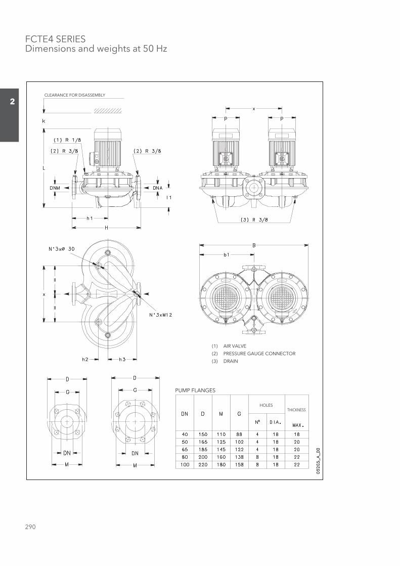
290
2
FCTE4 SERIES Dimensions and weights at 50 Hz
CLEARANCE FOR DISASSEMBLY
PUMP FLANGES
HOLESTHICKNESS
(1) AIR VALVE
(2) PRESSURE GAUGE CONNECTOR
(3) DRAIN
Sezione_02_uk.indd 290Sezione_02_uk.indd 290 07/03/12 16.1507/03/12 16.15

291
2
FCTE4 SERIES Dimensions and weights at 50 Hz
PUMP TYPE WEIGHT
B H L k
DNA DNM b1 h1 h2 h3 l1 p x kg
FCTE4 40-125/02A 40 40 245 170 50 120 89 140 250 490 320 420 90 46FCTE4 40-125/02 40 40 245 170 50 120 89 140 250 490 320 420 90 46FCTE4 40-160/02 40 40 245 170 50 120 89 140 250 490 320 420 90 48FCTE4 40-160/03 40 40 245 170 50 120 89 140 250 490 320 420 90 50FCTE4 40-200/05 40 40 348 220 50 190 97 155 360 695 440 460 101 83FCTE4 40-200/07 40 40 348 220 50 190 97 159 360 695 440 428 101 86FCTE4 40-250/11 40 40 348 220 50 190 97 174 360 695 440 495 101 123FCTE4 40-250/15 40 40 348 220 50 190 97 174 360 695 440 495 101 125FCTE4 50-125/02 50 50 250 180 55 130 92 140 260 500 340 425 91 49FCTE4 50-125/03 50 50 250 180 55 130 92 140 260 500 340 425 91 51FCTE4 50-160/05 50 50 250 180 55 130 92 155 260 500 340 457 91 53FCTE4 50-200/07 50 50 348 230 60 185 125 159 360 695 440 456 110 105FCTE4 50-200/11 50 50 348 230 60 185 125 174 360 695 440 523 110 122FCTE4 50-250/15 50 50 348 230 60 185 125 174 360 695 440 523 110 128FCTE4 50-250/22 50 50 348 230 60 185 125 214 360 695 440 547 110 140FCTE4 65-125/03 65 65 297 185 55 125 108 140 310 593 340 442 96 75FCTE4 65-125/05 65 65 297 185 55 125 108 155 310 593 340 474 96 83FCTE4 65-160/07 65 65 297 185 55 125 108 159 310 593 340 442 96 94FCTE4 65-160/11 65 65 297 185 55 125 108 174 310 593 340 509 96 107FCTE4 65-200/15 65 65 348 260 59 185 130 174 360 695 475 528 109 130FCTE4 65-250/22 65 65 348 260 59 185 130 214 360 695 475 552 109 152FCTE4 65-250/30 65 65 348 260 59 185 130 214 360 695 475 583 109 156FCTE4 80-125/07 80 80 304 210 70 110 141 159 320 607 400 481 106 101FCTE4 80-125/11 80 80 304 210 70 110 141 174 320 607 400 548 106 116FCTE4 80-200/15 80 80 368 280 80 140 157 174 380 722 500 555 112 153FCTE4 80-200/22 80 80 368 280 80 140 157 214 380 722 500 579 112 165FCTE4 80-200/30 80 80 368 280 80 140 157 214 380 722 500 610 112 173FCTE4 80-250/40 80 80 368 280 80 140 157 214 380 722 500 655 112 225FCTE4 80-250/55 80 80 368 280 80 140 157 256 380 722 500 662 112 241FCTE4 100-160/15 100 100 340 270 72 150 175 174 360 670 500 574 118 146FCTE4 100-200/22 100 100 408 310 80 150 180 214 410 798 550 602 128 201FCTE4 100-200/30 100 100 408 310 80 150 180 214 410 798 550 633 128 205FCTE4 100-250/40 100 100 408 310 80 150 180 214 410 798 550 678 128 253FCTE4 100-250/55 100 100 408 310 80 150 180 256 410 798 550 685 128 265FCTE4 100-250/75 100 100 408 310 80 150 180 256 410 798 550 685 128 285
fc_fcte4-4p50-en_c_td
DIMENSIONS (mm)
Sezione_02_uk.indd 291Sezione_02_uk.indd 291 07/03/12 16.1507/03/12 16.15
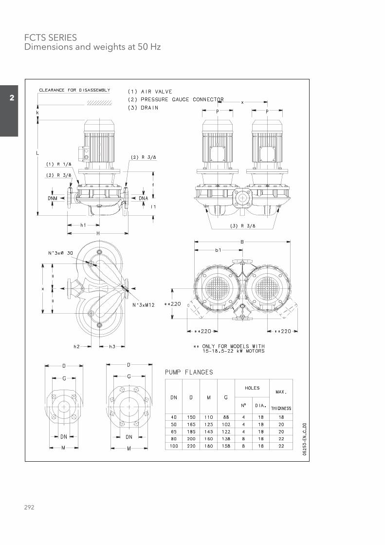
292
2
FCTS SERIES Dimensions and weights at 50 Hz
Sezione_02_uk.indd 292Sezione_02_uk.indd 292 07/03/12 16.1507/03/12 16.15

293
2
FCTS SERIES Dimensions and weights at 50 Hz
PUMP TYPE WEIGHT
B H L k
DNA DNM b1 f h1 h2 h3 l1 p x kg
FCTS 40-125/07 40 40 245 155 170 50 120 89 155 250 490 320 507 90 65FCTS 40-125/11 40 40 245 155 170 50 120 89 155 250 490 320 507 90 67FCTS 40-160/15 40 40 245 155 170 50 120 89 174 250 490 320 542 90 73FCTS 40-160/22 40 40 245 155 170 50 120 89 174 250 490 320 542 90 77FCTS 40-200/30 40 40 348 165 220 50 190 97 174 360 695 440 560 101 133FCTS 40-200/40 40 40 348 165 220 50 190 97 197 360 695 440 581 101 145FCTS 40-200/55 40 40 348 192 220 50 190 97 214 360 695 440 664 101 171FCTS 40-250/75 40 40 348 192 220 50 190 97 256 360 695 440 656 101 207FCTS 40-250/110 40 40 348 222 220 50 190 97 256 360 695 440 747 101 235FCTS 50-125/11 50 50 250 156 180 55 130 92 155 260 500 340 511 91 70FCTS 50-125/15 50 50 250 156 180 55 130 92 174 260 500 340 546 91 78FCTS 50-160/22 50 50 250 156 180 55 130 92 174 260 500 340 546 91 94FCTS 50-160/30 50 50 250 166 180 55 130 92 174 260 500 340 556 91 95FCTS 50-160/40 50 50 250 166 180 55 130 92 197 260 500 340 577 91 109FCTS50-200/55 50 50 348 192 230 60 185 125 214 360 695 440 692 110 178FCTS 50-200/75 50 50 348 192 230 60 185 125 256 360 695 440 684 110 212FCTS 50-250/110A 50 50 348 222 230 60 185 125 256 360 695 440 775 110 226FCTS 50-250/110 50 50 348 222 230 60 185 125 256 360 695 440 775 110 226FCTS 50-250/150 50 50 348 222 230 60 185 125 313 360 695 440 841 110 246FCTS 65-125/22 65 65 297 158 185 55 125 108 174 310 593 340 564 96 138FCTS 65-125/30 65 65 297 168 185 55 125 108 174 310 593 340 574 96 123FCTS 65-125/40 65 65 297 168 185 55 125 108 197 310 593 340 595 96 133FCTS 65-160/55 65 65 297 195 185 55 125 108 214 310 593 340 678 96 159FCTS 65-160/75 65 65 297 195 185 55 125 108 256 310 593 340 670 96 189FCTS 65-200/110A 65 65 348 222 260 59 185 130 256 360 695 475 780 109 258FCTS 65-200/110 65 65 348 222 260 59 185 130 256 360 695 475 780 109 258FCTS 65-250/150 65 65 348 222 260 59 185 130 313 360 695 475 846 109 260FCTS 65-250/185 65 65 348 222 260 59 185 130 313 360 695 475 846 109 272FCTS 65-250/220 65 65 348 222 260 59 185 130 313 360 695 475 846 109 292FCTS 80-125/30 80 80 304 174 210 70 110 141 174 320 607 400 613 106 162FCTS 80-125/40 80 80 304 174 210 70 110 141 197 320 607 400 634 106 164FCTS 80-125/55 80 80 304 201 210 70 110 141 214 320 607 400 717 106 170FCTS 80-160/75 80 80 304 201 210 70 110 141 256 320 607 400 709 106 202FCTS 80-200/110 80 80 368 222 280 80 140 157 256 380 722 500 807 112 251FCTS 80-200/150 80 80 368 222 280 80 140 157 313 380 722 500 873 112 271FCTS 80-200/185 80 80 368 222 280 80 140 157 313 380 722 500 873 112 291FCTS 80-200/220 80 80 368 222 280 80 140 157 313 380 722 500 873 112 315FCTS 100-160/110 100 100 340 223 270 72 150 175 256 360 670 500 826 118 268FCTS 100-200/185 100 100 408 222 310 80 150 180 313 410 798 550 896 128 384FCTS 100-200/220 100 100 408 222 310 80 150 180 313 410 798 550 896 128 407
fc_fcts-2p50-en_c_td
DIMENSIONS (mm)
Sezione_02_uk.indd 293Sezione_02_uk.indd 293 07/03/12 16.1507/03/12 16.15

294
2
FCTS4 SERIES Dimensions and weights at 50 Hz
PUMP FLANGES
HOLESTHICKNESS
(1) AIR VALVE
(2) PRESSURE GAUGE CONNECTOR
(3) DRAIN
CLEARANCE FOR DISASSEMBLY
Sezione_02_uk.indd 294Sezione_02_uk.indd 294 07/03/12 16.1507/03/12 16.15

295
2
FCTS4 SERIES Dimensions and weights at 50 Hz
PUMP TYPE WEIGHT
B H L k
DNA DNM b1 f h1 h2 h3 l1 p x max kg
FCTS4 40-200/05 40 40 348 155 220 50 190 97 155 360 695 440 515 101 107FCTS4 40-200/07 40 40 348 155 220 50 190 97 159 360 695 440 483 101 116FCTS4 40-250/11 40 40 348 155 220 50 190 97 174 360 695 440 550 101 129FCTS4 40-250/15 40 40 348 155 220 50 190 97 174 360 695 440 550 101 133FCTS4 50-200/07 50 50 348 155 230 60 185 125 159 360 695 440 511 110 123FCTS4 50-200/11 50 50 348 155 230 60 185 125 174 360 695 440 578 110 140FCTS4 50-250/15 50 50 348 155 230 60 185 125 174 360 695 440 578 110 142FCTS4 50-250/22 50 50 348 165 230 60 185 125 214 360 695 440 612 110 152FCTS4 65-160/07 65 65 297 158 185 55 125 108 159 310 593 340 497 96 98FCTS4 65-160/11 65 65 297 158 185 55 125 108 174 310 593 340 564 96 109FCTS4 65-200/15 65 65 348 155 260 59 185 130 174 360 695 475 583 109 136FCTS4 65-250/22 65 65 348 165 260 59 185 130 214 360 695 475 617 109 160FCTS4 65-250/30 65 65 348 165 260 59 185 130 214 360 695 475 648 109 166FCTS4 80-125/07 80 80 304 164 210 70 110 141 159 320 607 400 536 106 109FCTS4 80-125/11 80 80 304 164 210 70 110 141 174 320 607 400 603 106 130FCTS4 80-200/15 80 80 368 155 280 80 140 157 174 380 722 500 610 112 175FCTS4 80-200/22 80 80 368 165 280 80 140 157 214 380 722 500 644 112 181FCTS4 80-200/30 80 80 368 165 280 80 140 157 214 380 722 500 675 112 185FCTS4 80-250/40 80 80 368 165 280 80 140 157 214 380 722 500 720 112 241FCTS4 80-250/55 80 80 368 192 280 80 140 157 256 380 722 500 754 112 249FCTS4 100-160/15 100 100 340 156 270 72 150 175 174 360 670 500 629 118 154FCTS4 100-200/22 100 100 408 165 310 80 150 180 214 410 798 550 667 128 173FCTS4 100-200/30 100 100 408 165 310 80 150 180 214 410 798 550 698 128 179FCTS4 100-250/40 100 100 408 165 310 80 150 180 214 410 798 550 743 128 283FCTS4 100-250/55 100 100 408 192 310 80 150 180 256 410 798 550 777 128 287FCTS4 100-250/75 100 100 408 192 310 80 150 180 256 410 798 550 777 128 297
fc_fcts4-4p50-en_d_td
DIMENSIONS (mm)
Sezione_02_uk.indd 295Sezione_02_uk.indd 295 07/03/12 16.1507/03/12 16.15
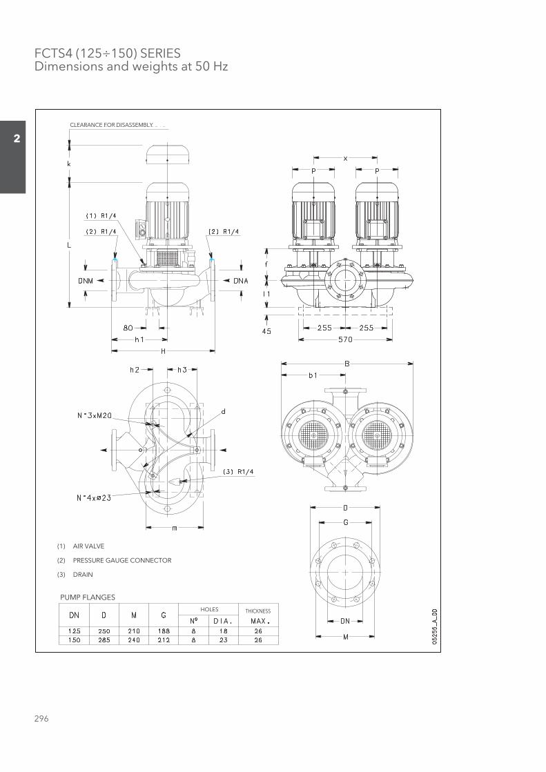
296
2
FCTS4 (125÷150) SERIESDimensions and weights at 50 Hz
PUMP FLANGES
HOLES THICKNESS
(1) AIR VALVE
(2) PRESSURE GAUGE CONNECTOR
(3) DRAIN
CLEARANCE FOR DISASSEMBLY
Sezione_02_uk.indd 296Sezione_02_uk.indd 296 07/03/12 16.1507/03/12 16.15
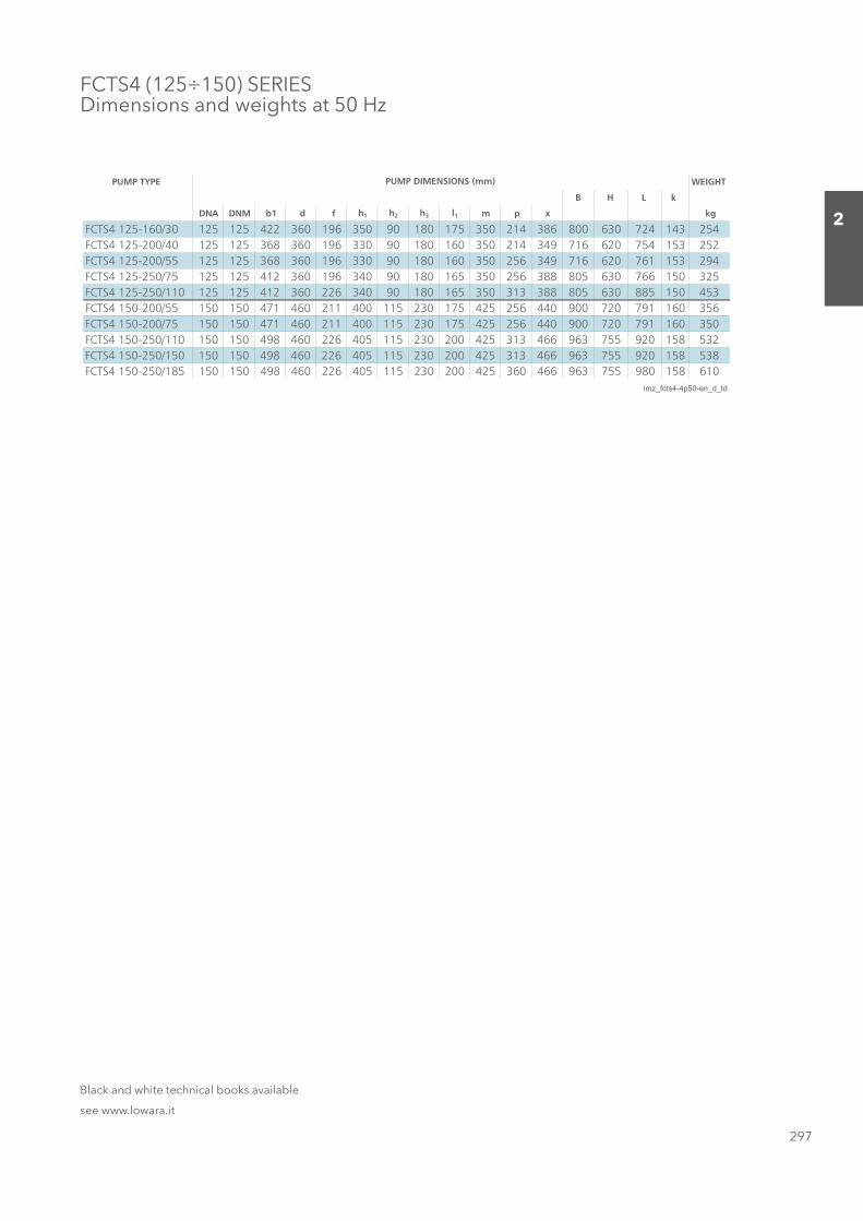
297
2
FCTS4 (125÷150) SERIESDimensions and weights at 50 Hz
PUMP TYPE WEIGHT
B H L k
DNA DNM b1 d f h1 h2 h3 l1 m p x kg
FCTS4 125-160/30 125 125 422 360 196 350 90 180 175 350 214 386 800 630 724 143 254FCTS4 125-200/40 125 125 368 360 196 330 90 180 160 350 214 349 716 620 754 153 252FCTS4 125-200/55 125 125 368 360 196 330 90 180 160 350 256 349 716 620 761 153 294FCTS4 125-250/75 125 125 412 360 196 340 90 180 165 350 256 388 805 630 766 150 325FCTS4 125-250/110 125 125 412 360 226 340 90 180 165 350 313 388 805 630 885 150 453FCTS4 150-200/55 150 150 471 460 211 400 115 230 175 425 256 440 900 720 791 160 356FCTS4 150-200/75 150 150 471 460 211 400 115 230 175 425 256 440 900 720 791 160 350FCTS4 150-250/110 150 150 498 460 226 405 115 230 200 425 313 466 963 755 920 158 532FCTS4 150-250/150 150 150 498 460 226 405 115 230 200 425 313 466 963 755 920 158 538FCTS4 150-250/185 150 150 498 460 226 405 115 230 200 425 360 466 963 755 980 158 610
lmz_fcts4-4p50-en_d_td
PUMP DIMENSIONS (mm)
Black and white technical books available
see www.lowara.it
Sezione_02_uk.indd 297Sezione_02_uk.indd 297 07/03/12 16.1507/03/12 16.15


![Refrigerated and Heated Bath Circulators [ES]](https://img.pdfslide.net/doc/110x75/589dacf21a28ab214a8be2bc/refrigerated-and-heated-bath-circulators-es.jpg)