Embed Size (px)
DESCRIPTION
Ciao
Citation preview
Catalyst 3560-C and 2960-C Switch Hardware Installation Guide September 2012
Americas HeadquartersCisco Systems, Inc.170 West Tasman DriveSan Jose, CA 95134-1706 USAhttp://www.cisco.comTel: 408 526-4000
800 553-NETS (6387)Fax: 408 527-0883
Text Part Number: OL-23803-02

THE SPECIFICATIONS AND INFORMATION REGARDING THE PRODUCTS IN THIS MANUAL ARE SUBJECT TO CHANGE WITHOUT NOTICE. ALL STATEMENTS, INFORMATION, AND RECOMMENDATIONS IN THIS MANUAL ARE BELIEVED TO BE ACCURATE BUT ARE PRESENTED WITHOUT WARRANTY OF ANY KIND, EXPRESS OR IMPLIED. USERS MUST TAKE FULL RESPONSIBILITY FOR THEIR APPLICATION OF ANY PRODUCTS.
THE SOFTWARE LICENSE AND LIMITED WARRANTY FOR THE ACCOMPANYING PRODUCT ARE SET FORTH IN THE INFORMATION PACKET THAT SHIPPED WITH THE PRODUCT AND ARE INCORPORATED HEREIN BY THIS REFERENCE. IF YOU ARE UNABLE TO LOCATE THE SOFTWARE LICENSE OR LIMITED WARRANTY, CONTACT YOUR CISCO REPRESENTATIVE FOR A COPY.
The following information is for FCC compliance of Class A devices: This equipment has been tested and found to comply with the limits for a Class A digital device, pursuant to part 15 of the FCC rules. These limits are designed to provide reasonable protection against harmful interference when the equipment is operated in a commercial environment. This equipment generates, uses, and can radiate radio-frequency energy and, if not installed and used in accordance with the instruction manual, may cause harmful interference to radio communications. Operation of this equipment in a residential area is likely to cause harmful interference, in which case users will be required to correct the interference at their own expense.
The following information is for FCC compliance of Class B devices: This equipment has been tested and found to comply with the limits for a Class B digital device, pursuant to part 15 of the FCC rules. These limits are designed to provide reasonable protection against harmful interference in a residential installation. This equipment generates, uses and can radiate radio frequency energy and, if not installed and used in accordance with the instructions, may cause harmful interference to radio communications. However, there is no guarantee that interference will not occur in a particular installation. If the equipment causes interference to radio or television reception, which can be determined by turning the equipment off and on, users are encouraged to try to correct the interference by using one or more of the following measures:
• Reorient or relocate the receiving antenna.
• Increase the separation between the equipment and receiver.
• Connect the equipment into an outlet on a circuit different from that to which the receiver is connected.
• Consult the dealer or an experienced radio/TV technician for help.
Modifications to this product not authorized by Cisco could void the FCC approval and negate your authority to operate the product.
The Cisco implementation of TCP header compression is an adaptation of a program developed by the University of California, Berkeley (UCB) as part of UCB’s public domain version of the UNIX operating system. All rights reserved. Copyright © 1981, Regents of the University of California.
NOTWITHSTANDING ANY OTHER WARRANTY HEREIN, ALL DOCUMENT FILES AND SOFTWARE OF THESE SUPPLIERS ARE PROVIDED “AS IS” WITH ALL FAULTS. CISCO AND THE ABOVE-NAMED SUPPLIERS DISCLAIM ALL WARRANTIES, EXPRESSED OR IMPLIED, INCLUDING, WITHOUT LIMITATION, THOSE OF MERCHANTABILITY, FITNESS FOR A PARTICULAR PURPOSE AND NONINFRINGEMENT OR ARISING FROM A COURSE OF DEALING, USAGE, OR TRADE PRACTICE.
Cisco and the Cisco logo are trademarks or registered trademarks of Cisco and/or its affiliates in the U.S. and other countries. To view a list of Cisco trademarks, go to this URL: www.cisco.com/go/trademarks. Third-party trademarks mentioned are the property of their respective owners. The use of the word partner does not imply a partnership relationship between Cisco and any other company. (1110R)
Any Internet Protocol (IP) addresses used in this document are not intended to be actual addresses. Any examples, command display output, and figures included in the document are shown for illustrative purposes only. Any use of actual IP addresses in illustrative content is unintentional and coincidental.
Catalyst 3560-C and 2960-C Switch Hardware Installation Guide© 2011–2012 Cisco Systems, Inc. All rights reserved.
OL-23803-02
C O N T E N T S
Preface vii
Related Publications i-viii
Obtaining Documentation and Submitting a Service Request i-viii
C H A P T E R 1 Product Overview 1-1
Switch Models 1-1
Front Panel 1-2
10/100 and 10/100/1000 Fast Ethernet Downlink Ports 1-5
PoE Ports (Switches with PoE Ports) 1-5
PoE Pass-Through 1-6
PoE Uplink Ports (Catalyst 2960CPD-8TT-L, 2960CPD-8PT-L, and 3560CPD-8PT-S) 1-8
PoE-Capable Downlink Ports (Catalyst 2960CPD-8PT-L, 3560CG-8PC-S, 3560CPD-8PT-S, 2960C-8PC-L, 2960C-12PC-L, 3560C-8PC-S, and 3560C-12PC-S) 1-8
USB Type A Port 1-8
Dual-Purpose Ports 1-9
SFP Modules 1-9
Management Ports 1-10
LEDs 1-11
Switch Panel LEDs 1-11
System LED 1-12
Console LEDs 1-12
Modes for Port LEDs 1-13
Port LEDs 1-13
PoE LED 1-14
PD LED 1-14
Dual-Purpose Port LEDs 1-14
Rear Panel 1-15
Internal Power Supply 1-16
Auxiliary Power Adapter 1-16
Security Slots 1-17
Reset Button 1-17
Management Options 1-17
Network Configurations 1-18
iiiCatalyst 3560-C and 2960-C Switch Hardware Installation Guide
Contents
C H A P T E R 2 Switch Installation 2-1
Preparing for Installation 2-1
Warnings 2-1
Installation Guidelines 2-3
Equipment That You Supply 2-4
Box Contents 2-4
Powering the Switch 2-4
Verifying Switch Operation 2-5
Mounting the Switch 2-5
On a Desk or Shelf (without Mounting Screws) 2-6
Desk, Shelf, or Wall (with Mounting Screws) 2-6
Desk- or Shelf-Mounting 2-6
Under the Desk- or Shelf-Mounting 2-8
Wall-Mounting 2-10
With a Mounting Tray 2-13
Mounting Tray with Screws 2-13
Mounting Tray with a Magnet 2-15
In a Rack 2-18
Attaching Brackets to the Switch 2-18
Mounting the Switch in a Rack 2-19
On a DIN Rail 2-20
Attaching the DIN-Mount Tray to the Switch 2-20
Mounting the Switch on a DIN Rail 2-21
Removing the Switch from a DIN Rail 2-23
Installing a Cover for the Reset Button (Optional) 2-24
Installing the Power Cord Retainer (Optional) 2-25
Installing the Cable Guard (Optional) 2-28
After Installing the Switch 2-31
Installing SFP Modules 2-31
Removing SFP Modules 2-32
Connecting Devices to the Ethernet Ports 2-33
Connecting to the 10/100 and 10/100/1000 Ports 2-33
Connecting to the PoE Ports 2-34
Where to Go Next 2-35
ivCatalyst 3560-C and 2960-C Switch Hardware Installation Guide
OL-23803-02
Contents
C H A P T E R 3 Troubleshooting 3-1
Diagnosing Problems 3-1
Switch POST Results 3-1
Switch LEDs 3-2
Switch Connections 3-2
Bad or Damaged Cable 3-2
Ethernet and Fiber-Optic Cables 3-2
Link Status 3-2
10/100 and 10/100/1000 Port Connections 3-3
10/100 PoE or PoE+ Port Connections 3-3
SFP Module 3-3
Interface Settings 3-3
Ping End Device 3-3
Spanning Tree Loops 3-4
Switch Performance 3-4
Speed, Duplex, and Autonegotiation 3-4
Autonegotiation and Network Interface Cards 3-4
Cabling Distance 3-4
Resetting the Switch 3-5
Finding the Switch Serial Number 3-5
A P P E N D I X A Technical Specifications A-1
A P P E N D I X B Connector and Cable Specifications B-1
Connector Specifications B-1
10/100 and 10/100/1000 Ports B-1
SFP Module Connectors B-2
Dual-Purpose Ports B-2
Cables and Adapters B-3
SFP Module Cables B-3
Cable Pinouts B-4
Console Port Adapter Pinouts B-5
vCatalyst 3560-C and 2960-C Switch Hardware Installation Guide
OL-23803-02
Contents
A P P E N D I X C Configuring the Switch with the CLI Setup Program C-1
Accessing the CLI Through the Console Port C-1
RJ-45 Console Port C-1
USB Mini-Type B Console Port C-3
Installing the Cisco Microsoft Windows USB Device Drivers C-4
Installing the Cisco Microsoft Windows XP USB Driver C-4
Installing the Cisco Microsoft Windows 2000 USB Driver C-5
Installing the Cisco Microsoft Windows Vista and Windows 7 USB Driver C-5
Uninstalling the Cisco Microsoft Windows USB Drivers C-6
Uninstalling the Cisco Microsoft Windows XP and 2000 USB Driver C-6
Uninstalling the Cisco Microsoft Windows Vista and Windows 7 USB Driver C-6
Entering the Initial Configuration Information C-7
IP Settings C-7
Completing the Setup Program C-7
viCatalyst 3560-C and 2960-C Switch Hardware Installation Guide
OL-23803-02
Preface
This guide describes the hardware features of the Catalyst 3560-C and 2960-C switches. It describes the physical and performance characteristics of the switch, explains how to install it, and provides troubleshooting information.
This guide does not describe system messages that you might receive or how to configure your switch. See the switch software configuration guide, the switch command reference, and the switch system message guide on Cisco.com.
Note Means reader take note. Notes contain helpful suggestions or references to materials not contained in this manual.
Caution Means reader be careful. In this situation, you might do something that could result in equipment damage or loss of data.
The safety warnings for this product are translated into several languages in the Regulatory Compliance and Safety Information for the Catalyst 3560-C and 2960-C Switches that is available on Cisco.com. The EMC regulatory statements are also included in that guide.
Warning IMPORTANT SAFETY INSTRUCTIONS
This warning symbol means danger. You are in a situation that could cause bodily injury. Before you work on any equipment, be aware of the hazards involved with electrical circuitry and be familiar with standard practices for preventing accidents. Use the statement number provided at the end of each warning to locate its translation in the translated safety warnings that accompanied this device. Statement 1071
SAVE THESE INSTRUCTIONS
viiCatalyst 3560-C and 2960-C Switch Hardware Installation Guide
OL-23803-02
PrefaceRelated Publications
Related Publicationshttp://www.cisco.com/go/cat3560c_docs
http://www.cisco.com/go/cat2960c_docs
Note Before installing, configuring, or upgrading the switch, see the release notes on Cisco.com for the latest information.
• Release Notes for the Catalyst 3560-C Switch
• Release Notes for the Catalyst 2960-C Switch
• Catalyst 3560-C and 2960-C Switch Getting Started Guide
• Regulatory Compliance and Safety Information for the Catalyst 3560-C and 2960-C Switches
• Catalyst 2960 and 2960-S Switch Software Configuration Guide
• Catalyst 2960 and 2960-S Switch Command Reference
• Catalyst 3560 Switch Software Configuration Guide
• Catalyst 3560 Switch Command Reference
• Catalyst 3750, 3560, 3550, 2975, 2970, 2960, and 2960-S Switch System Message Guide
For other information about related products, see these documents:
• Smart Install Configuration Guide
• Auto Smartports Configuration Guide
• Cisco EnergyWise Configuration Guide
Cisco SFP module documents:
http://www.cisco.com/en/US/products/hw/modules/ps5455/prod_installation_guides_list.html
SFP module compatibility matrix documents:
http://www.cisco.com/en/US/products/hw/modules/ps5455/products_device_support_tables_list.html
Obtaining Documentation and Submitting a Service RequestFor information on obtaining documentation, submitting a service request, and gathering additional information, see the monthly What’s New in Cisco Product Documentation, which also lists all new and revised Cisco technical documentation, at:
http://www.cisco.com/en/US/docs/general/whatsnew/whatsnew.html
Subscribe to the What’s New in Cisco Product Documentation as a Really Simple Syndication (RSS) feed and set content to be delivered directly to your desktop using a reader application. The RSS feeds are a free service and Cisco currently supports RSS version 2.0.
viiiCatalyst 3560-C and 2960-C Switch Hardware Installation Guide
OL-23803-02
Catalyst 356OL-23803-02
C H A P T E R 1
Product OverviewThe Catalyst 3560-C and 2960-C of switches, also referred to as the switch, are Ethernet switches to which you can connect devices such as Cisco IP Phones, Cisco Wireless Access Points, workstations, and other network devices such as servers, routers, and other switches.
You can deploy these switches outside of the traditional wiring closet environment, such as in office workspaces, hotel rooms, slot machines, kiosks, and classrooms. The switch is suitable for deployments where there are space and power constraints (access to power outlets).
See the switch software configuration guide for deployment examples.
• Switch Models, page 1-1
• Front Panel, page 1-2
• Rear Panel, page 1-15
• Management Options, page 1-17
Switch ModelsTable 1-1 Switch Model Descriptions
Switch Model Description
Catalyst 2960CPD-8TT-L 8 10/100 Ethernet ports and 2 10/100/1000BASE-T PD uplink copper ports.
Catalyst 2960CPD-8PT-L 8 10/100 PoE1 ports and 2 10/100/1000BASE-T PD uplink copper ports.
Catalyst 2960CG-8TC-L 8 10/100/1000 Ethernet ports and 2 dual-purpose ports (1 10/100/1000BASE-T copper port and 1 SFP2 module slot).
Catalyst 2960C-8TC-L 8 10/100 Ethernet ports and 2 dual-purpose ports.
Catalyst 2960C-8TC-S 8 10/100 Ethernet ports and 2 dual-purpose ports.
Catalyst 2960C-8PC-L 8 10/100 PoE ports and 2 dual-purpose ports.
Catalyst 2960C-12PC-L 12 10/100 PoE ports and 2 dual-purpose ports.
Catalyst 3560CG-8PC-S 8 10/100/1000 PoE+ ports and 2 dual-purpose ports.
Catalyst 3560CG-8TC-S 8 10/100/1000 Ethernet ports and 2 dual-purpose ports.
Catalyst 3560CPD-8PT-S 8 10/100/1000 PoE ports and 2 10/100/1000BASE-T PD uplink copper ports.
1-10-C and 2960-C Switch Hardware Installation Guide
Chapter 1 Product OverviewFront Panel
Front Panel• 8 or 12 downlink Ethernet ports of one of these types:
– 10/100
– 10/100/1000
– 10/100 PoE
– 10/100 PoE+
– 10/100/1000 PoE
– 10/100/1000 PoE+
• Two 10/100/1000 uplink ports or two dual purpose ports
• RJ-45 console port
• USB mini-Type B (console) port
• USB Type A port (available on the Catalyst 3560CPD-8PT-S, 2960CG-8TC-L, 3560CG-8PC-S, and 3560CG-8TC-S switches)
• LEDs
All the 8-port and 12-port switches have similar components. See Figure 1-1, Figure 1-2, Figure 1-3, Figure 1-4, and Figure 1-5 for examples.
Catalyst 3560C-8PC-S 8 10/100 PoE+ ports and 2 dual-purpose ports.
Catalyst 3560C-12PC-S 12 10/100 PoE+ ports and 2 dual-purpose ports.
1. PoE = Power over Ethernet
2. SFP = small form-factor pluggable
Table 1-1 Switch Model Descriptions (continued)
Switch Model Description
1-2Catalyst 3560-C and 2960-C Switch Hardware Installation Guide
OL-23803-02
Chapter 1 Product OverviewFront Panel
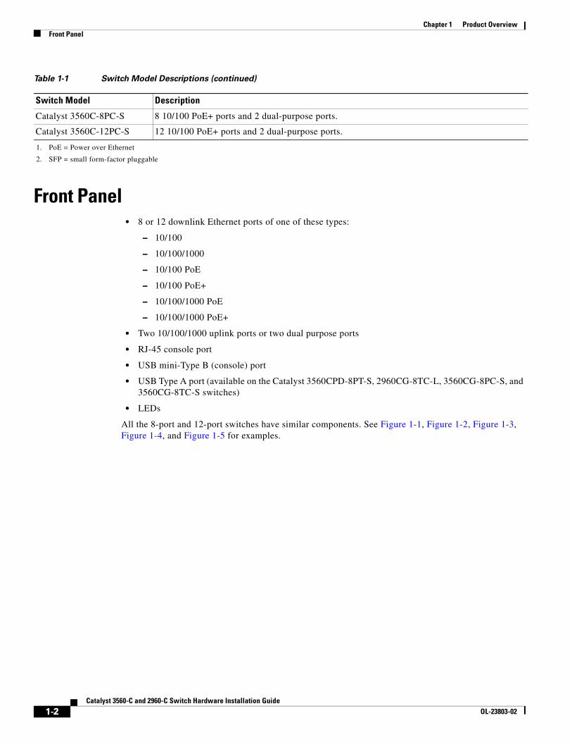
Figure 1-1 Catalyst 2960CPD-8PT-L Front Panel View
Figure 1-2 Catalyst 3560CG-8PC-S Front Panel View
1 Mode button 4 LEDs
2 USB mini-Type B (console) port 5 10/100 PoE ports
3 RJ-45 console port 6 10/100/1000 uplink ports
M O DE
CO NSO LE
12
SeriesPD
PO W ER OVER ETHERNET
12
34
56
78
PD
SPD
PoE
DPLX
STAT
SYST
2823
91
2
5
1
6
3 4
1 Mode button 5 LEDs
2 USB Type A port 6 10/100/1000 PoE+ ports
3 USB mini-Type B (console) port 7 Dual-purpose ports
4 RJ-45 console port
M O DE
CO NSO LE
9
Catalyst 3560-CG SeriesPoE
PO W ER OVER ETHERNET
12
34
SPD
PoE
DPLX
STAT
SYST
56
78
10
2088
68
3
6
1 2
7
4 5
1-3Catalyst 3560-C and 2960-C Switch Hardware Installation Guide
OL-23803-02
Chapter 1 Product OverviewFront Panel
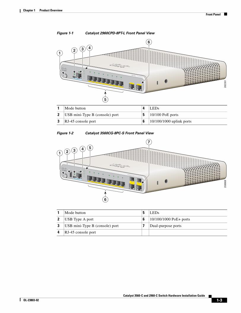
Figure 1-3 Catalyst 3560CPD-8PT-S Front Panel View
Figure 1-4 Catalyst 2960C-12PC-L Front Panel View
1 Mode button 5 LEDs
2 USB Type A port 6 10/100/1000 PoE ports
3 USB mini-Type B (console) port 7 10/100/1000 uplink ports
4 RJ-45 console port
M O DE
CO NSO LE
Catalyst 3560-CG SeriesPD
PO W ER OVER ETHERNET
12
34
SPD
PoE
PD
DPLX
STAT
SYST
56
78
12
2088
67
3
6
1 2
7
4 5
1 Mode button 4 LEDs
2 USB mini-Type B (console) port 5 10/100 PoE ports
3 RJ-45 console port 6 Dual-purpose ports
M ODE
CONSOLE
12
Catalyst 2960-C SeriesPoE
POW EROVERETHERNET
SPD
PoE
DPLX
STAT
SYST
1
2
3
4
5
6
7
8
9
10
11
12
2554
91
2
5
13 4
6
1-4Catalyst 3560-C and 2960-C Switch Hardware Installation Guide
OL-23803-02
Chapter 1 Product OverviewFront Panel
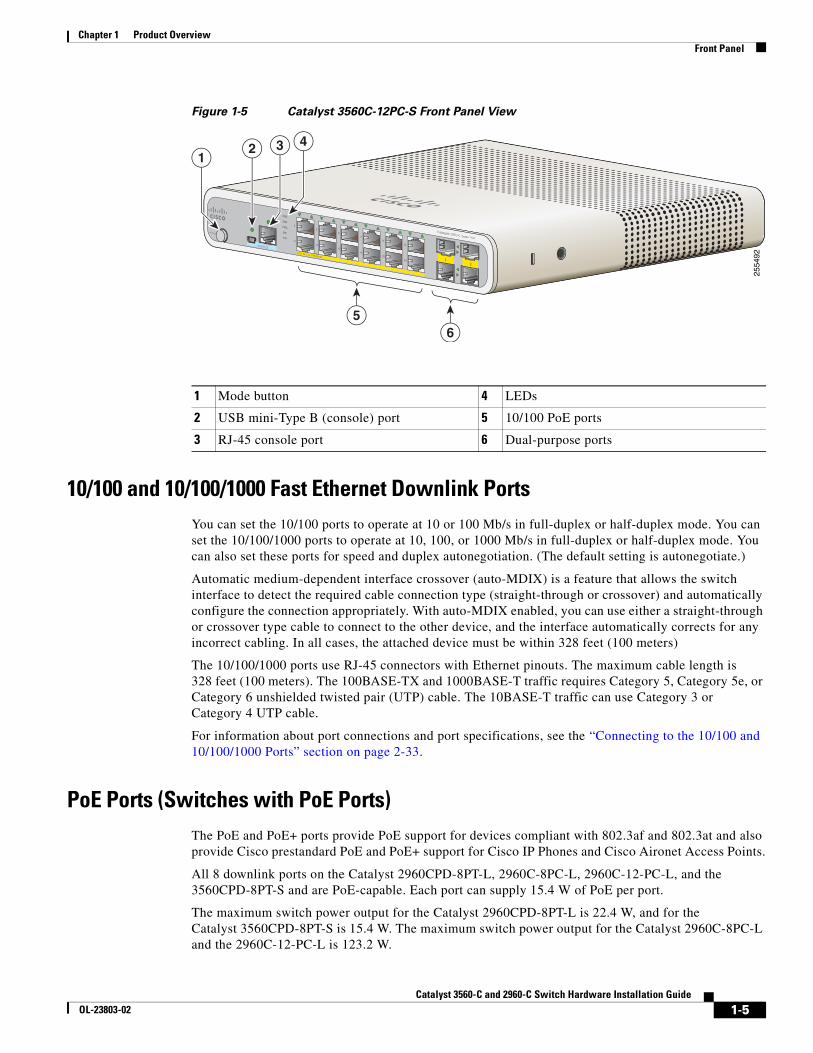
Figure 1-5 Catalyst 3560C-12PC-S Front Panel View
10/100 and 10/100/1000 Fast Ethernet Downlink PortsYou can set the 10/100 ports to operate at 10 or 100 Mb/s in full-duplex or half-duplex mode. You can set the 10/100/1000 ports to operate at 10, 100, or 1000 Mb/s in full-duplex or half-duplex mode. You can also set these ports for speed and duplex autonegotiation. (The default setting is autonegotiate.)
Automatic medium-dependent interface crossover (auto-MDIX) is a feature that allows the switch interface to detect the required cable connection type (straight-through or crossover) and automatically configure the connection appropriately. With auto-MDIX enabled, you can use either a straight-through or crossover type cable to connect to the other device, and the interface automatically corrects for any incorrect cabling. In all cases, the attached device must be within 328 feet (100 meters)
The 10/100/1000 ports use RJ-45 connectors with Ethernet pinouts. The maximum cable length is 328 feet (100 meters). The 100BASE-TX and 1000BASE-T traffic requires Category 5, Category 5e, or Category 6 unshielded twisted pair (UTP) cable. The 10BASE-T traffic can use Category 3 or Category 4 UTP cable.
For information about port connections and port specifications, see the “Connecting to the 10/100 and 10/100/1000 Ports” section on page 2-33.
PoE Ports (Switches with PoE Ports)The PoE and PoE+ ports provide PoE support for devices compliant with 802.3af and 802.3at and also provide Cisco prestandard PoE and PoE+ support for Cisco IP Phones and Cisco Aironet Access Points.
All 8 downlink ports on the Catalyst 2960CPD-8PT-L, 2960C-8PC-L, 2960C-12-PC-L, and the 3560CPD-8PT-S and are PoE-capable. Each port can supply 15.4 W of PoE per port.
The maximum switch power output for the Catalyst 2960CPD-8PT-L is 22.4 W, and for the Catalyst 3560CPD-8PT-S is 15.4 W. The maximum switch power output for the Catalyst 2960C-8PC-L and the 2960C-12-PC-L is 123.2 W.
1 Mode button 4 LEDs
2 USB mini-Type B (console) port 5 10/100 PoE ports
3 RJ-45 console port 6 Dual-purpose ports
M ODE
CONSOLE
12
Catalyst 3960-C SeriesPoE
POW EROVERETHERNET
SPD
PoE
DPLX
STAT
SYST
1
2
3
4
5
6
7
8
9
10
11
12
2554
92
2
56
13 4
1-5Catalyst 3560-C and 2960-C Switch Hardware Installation Guide
OL-23803-02
Chapter 1 Product OverviewFront Panel
All 8 or 12 downlink ports on the Catalyst,3560CG-8PC-S, 3560C-8PC-S, and 3560C-12PC-S switches are PoE+ capable. The maximum switch power output is 123.2 W. You can budget the PoE and PoE+:
• 15.4 W of PoE output on eight ports
• 30 W of PoE+ on four ports
On a per-port basis, you control whether or not a port automatically provides power when an IP phone or an access point is connected.
The 10/100/1000 PoE ports use RJ-45 connectors with Ethernet pinouts. The maximum cable length is 328 feet (100 meters). The 100BASE-TX and 1000BASE-T traffic requires Category 5, Category 5e, or Category 6 unshielded twisted pair (UTP) cable. The 10BASE-T traffic can use Category 3 or Category 4 UTP cable.
Cisco intelligent power management capabilities include enhanced power negotiation, power reservation, and per-port power policing. For information about configuring and monitoring PoE ports, see the switch software configuration guide on Cisco.com.
For information about port connections and port specifications, see the “Connecting to the 10/100 and 10/100/1000 Ports” section on page 2-33.
Note The output of the PoE circuit has been evaluated as a Limited Power Source (LPS) per IEC 60950-1.
PoE Pass-Through
The Catalyst 2960CPD-8PT-L and 3560CPD-8PT-S switches provide PoE pass-through. The Catalyst 2960CPD-8PT-L is powered either through the 10/100/1000 PoE uplink ports receiving power from a PoE or PoE+ switch or through an auxiliary power adapter. The Catalyst 3560CPD-8PT-S is powered through the 10/100/1000 PoE uplink ports receiving power from a PoE+ switch or through an auxiliary power adapter. If the switch has surplus power (see Table 1-2), it can power other PoE-capable devices such as IP phones, access points, and so on. See Figure 1-6.
See the “Powering the Switch” section on page 2-4 for information on powering the switches.
1-6Catalyst 3560-C and 2960-C Switch Hardware Installation Guide
OL-23803-02
Chapter 1 Product OverviewFront Panel
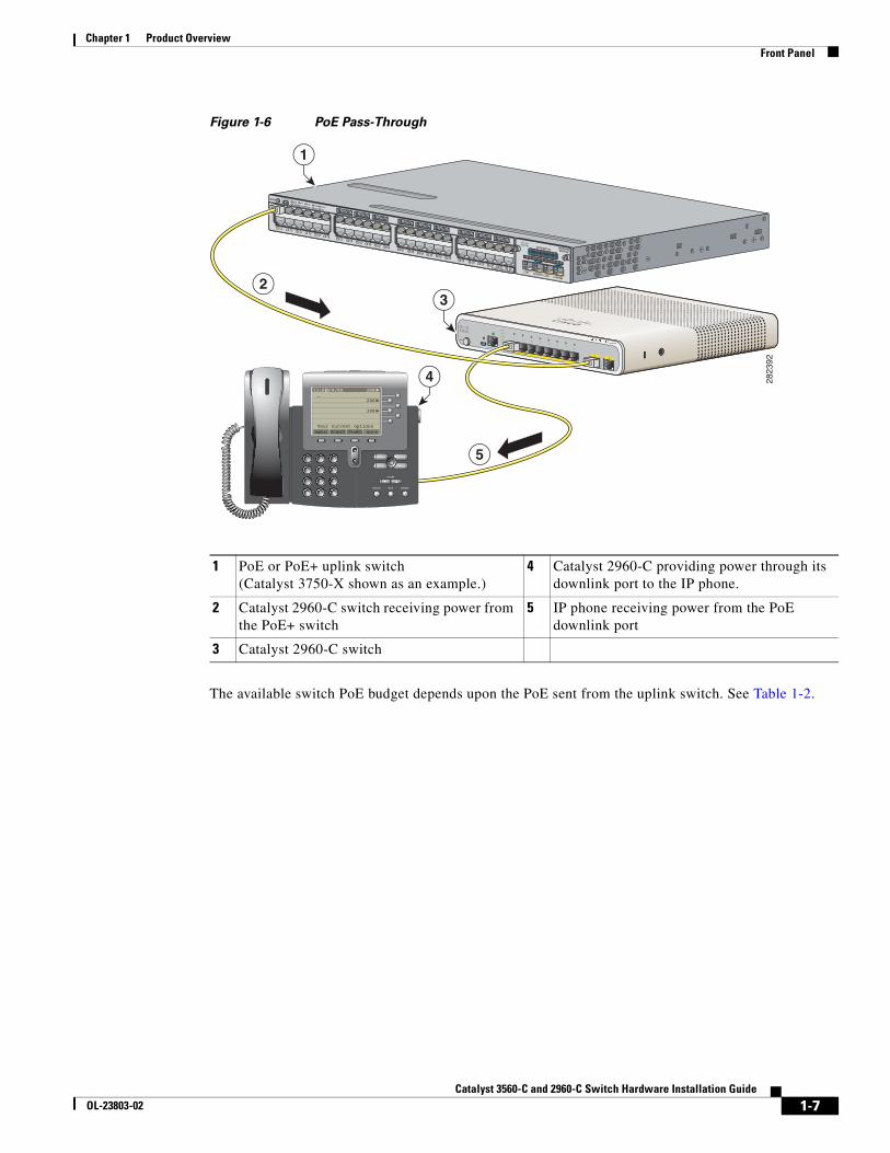
Figure 1-6 PoE Pass-Through
The available switch PoE budget depends upon the PoE sent from the uplink switch. See Table 1-2.
1 PoE or PoE+ uplink switch(Catalyst 3750-X shown as an example.)
4 Catalyst 2960-C providing power through its downlink port to the IP phone.
2 Catalyst 2960-C switch receiving power from the PoE+ switch
5 IP phone receiving power from the PoE downlink port
3 Catalyst 2960-C switch
2823
92
Catalyst 3750-X PoE+48
SYST XPSSTAT
SPEED DUPLX
EN
PoESTACK
MASTS-PWR
MODE CONSOLE
1 23 4
5 67 8
9 1011 12
13 1415 16
17 1819 20
21 2223 24
25 2627 28
29 3031 32
33 3435 36
37 3839 40
41 4243 44
45 4647 48
C3KX-NM-10GNETWORKMODULE
G1G2/TE1 G3
G4/TE2
MODE
CONSOLE
12
Series PD
POWER OVER ETHERNET
12
34
56
78
PD
SPD
PoE
DPLX
STAT
SYST
messages directory
services settings
VOLUME
HEADSET MUTE SPEAKER
2ABC
1 3DEF
7PQRS
4GHI
5JKL
6MNO
8TUV
9WXYZ
0OPER
moreCFwdAllNewCallRedial
2000
2000
3000
Your current options
_13:0210/9/00
4
1
32
5
1-7Catalyst 3560-C and 2960-C Switch Hardware Installation Guide
OL-23803-02
Chapter 1 Product OverviewFront Panel
PoE Uplink Ports (Catalyst 2960CPD-8TT-L, 2960CPD-8PT-L, and 3560CPD-8PT-S)
The 10/100/1000 PoE uplink ports on the Catalyst 2960CPD-8TT-L and 2960CPD-8PT-L can receive power from a PoE or PoE+ switch. The 10/100/1000 PoE uplink ports on the Catalyst 3560CPD-8PT-S can receive power from a PoE+ switch. You can connect each of the uplink ports to different PoE switches or to the same PoE switch. See Figure 1-6.
Note You can also use an external auxiliary power adapter that connects to the rear of the switch. You can order it from your Cisco representative. See the “Auxiliary Power Adapter” section on page 1-16 for information.
PoE-Capable Downlink Ports (Catalyst 2960CPD-8PT-L, 3560CG-8PC-S, 3560CPD-8PT-S, 2960C-8PC-L, 2960C-12PC-L, 3560C-8PC-S, and 3560C-12PC-S)
Depending upon the available PoE budget, these switches can power other PoE-capable devices such as IP phones, access points, and so on. See Table 1-2 for PoE budgeting information. See Figure 1-6.
For information on powering the switches, see the “Powering the Switch” section on page 2-4.
USB Type A PortSome models have an USB Type A port. This port provides access to external Cisco USB flash devices (also known as thumb drives or USB keys). The port supports Cisco USB flash drives with capacities from 64 MB to 1 GB.
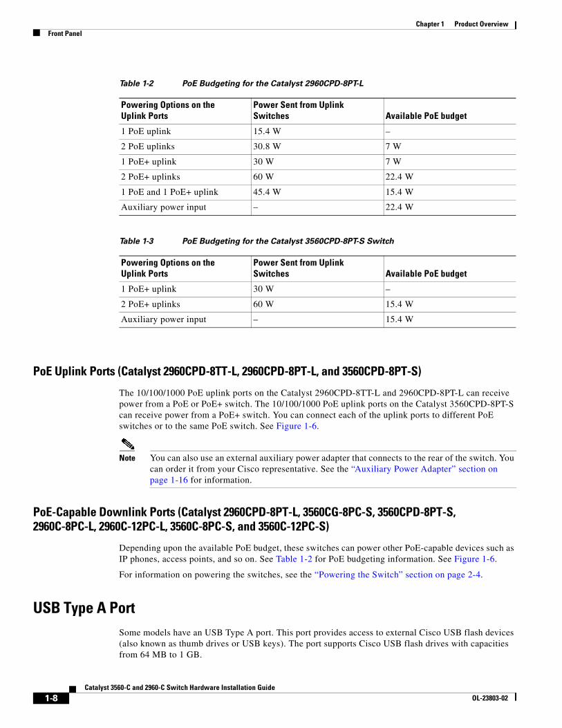
Table 1-2 PoE Budgeting for the Catalyst 2960CPD-8PT-L
Powering Options on the Uplink Ports
Power Sent from Uplink Switches Available PoE budget
1 PoE uplink 15.4 W –
2 PoE uplinks 30.8 W 7 W
1 PoE+ uplink 30 W 7 W
2 PoE+ uplinks 60 W 22.4 W
1 PoE and 1 PoE+ uplink 45.4 W 15.4 W
Auxiliary power input – 22.4 W
Table 1-3 PoE Budgeting for the Catalyst 3560CPD-8PT-S Switch
Powering Options on the Uplink Ports
Power Sent from Uplink Switches Available PoE budget
1 PoE+ uplink 30 W –
2 PoE+ uplinks 60 W 15.4 W
Auxiliary power input – 15.4 W
1-8Catalyst 3560-C and 2960-C Switch Hardware Installation Guide
OL-23803-02
Chapter 1 Product OverviewFront Panel
Cisco IOS software provides standard file system access to the flash device: read, write, erase, and copy, as well as the capability to format the flash device with a FAT file system.
For more information about the switch management ports, see the switch software configuration guide and the command reference on Cisco.com.
Dual-Purpose PortsYou can configure the dual-purpose ports on the switch as either 10/100/1000 ports or as SFP-module ports. You can set the 10/100/1000 ports to autonegotiate, or you can configure them as fixed 10, 100, or 1000 Mb/s (Gigabit) Ethernet ports.
By default, the switch selects the medium for each dual-purpose port (10/100/1000BASE-T or SFP). When a link is achieved on one media type, the switch disables the other media type until the active link goes down. If links are active on both media, the SFP-module port has priority, but you can use the media-type interface configuration command to manually designate the port as an RJ-45 port or an SFP port.
You can configure the speed and duplex settings consistent with the selected media type. For information on configuring interfaces, see the switch software configuration guide.
SFP Modules
The switch Ethernet SFP modules provide connections to other devices. These field-replaceable transceiver modules provide the uplink interfaces.The modules have LC connectors for fiber-optic connections or RJ-45 connectors for copper connections.
You can use any combination of these supported SFP modules:
• GLC-LH-SM=
• GLC-SX-MM=
• GLC-ZX-SM=
• GLC-BX-D=
• GLC-BX-U=
• GLC-FE-100FX=
• GLC-FE-100LX=
• GLC-FE-100BX-D=
• GLC-FE-100BX-U=
• CWDM SFPs
For information about SFP modules, see your SFP module documentation and the “Installing SFP Modules” section on page 2-31. For cable specifications, see the “SFP Module Cables” section on page B-3.
1-9Catalyst 3560-C and 2960-C Switch Hardware Installation Guide
OL-23803-02
Chapter 1 Product OverviewFront Panel
Management PortsYou can connect the switch to a PC running Microsoft Windows or to a terminal server through either the RJ-45 console port or the USB mini-Type B console port, also referred to as the USB-mini console port.
• RJ-45 console port. The RJ-45 connection uses an RJ-45-to-DB-9 female cable.
• USB-mini console port (5-pin connector). The USB connection uses a USB Type A-to-5-pin mini-Type B cable.
The USB-mini console interface speeds are the same as the RJ-45 console interface speeds.
To use the USB-mini console port, you must install the Cisco Windows USB device driver on the device that is connected to the USB-mini console port and that is running Microsoft Windows.
Note For information about downloading the Cisco USB device driver, see the “Installing the Cisco Microsoft Windows USB Device Drivers” section on page C-4.
With the Cisco Windows USB device driver, connecting and disconnecting the USB cable from the console port does not affect Windows HyperTerminal operations. Mac OS X or Linux require no special drivers.
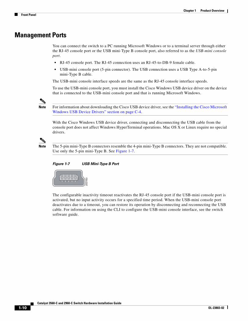
Note The 5-pin mini-Type B connectors resemble the 4-pin mini-Type B connectors. They are not compatible. Use only the 5-pin mini-Type B. See Figure 1-7.
Figure 1-7 USB Mini-Type B Port
The configurable inactivity timeout reactivates the RJ-45 console port if the USB-mini console port is activated, but no input activity occurs for a specified time period. When the USB-mini console port deactivates due to a timeout, you can restore its operation by disconnecting and reconnecting the USB cable. For information on using the CLI to configure the USB-mini console interface, see the switch software guide.
2531
63
1-10Catalyst 3560-C and 2960-C Switch Hardware Installation Guide
OL-23803-02
Chapter 1 Product OverviewFront Panel
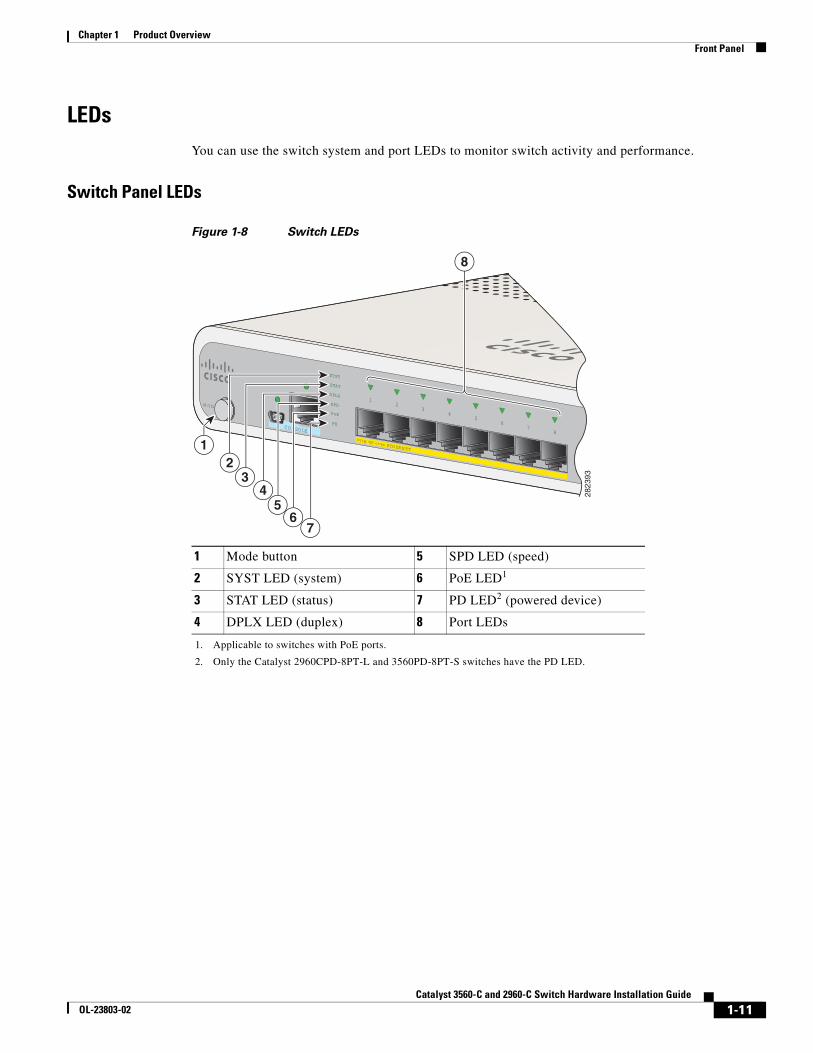
LEDsYou can use the switch system and port LEDs to monitor switch activity and performance.
Switch Panel LEDs
Figure 1-8 Switch LEDs
1 Mode button 5 SPD LED (speed)
2 SYST LED (system) 6 PoE LED1
1. Applicable to switches with PoE ports.
3 STAT LED (status) 7 PD LED2 (powered device)
2. Only the Catalyst 2960CPD-8PT-L and 3560PD-8PT-S switches have the PD LED.
4 DPLX LED (duplex) 8 Port LEDs
M O DE
CO NSO LE
PO W ER OVER ETHERNET
12
34
56
78
PD
SPD
PoE
DPLX
STAT
SYST
2823
93
67
5
8
23
4
1
1-11Catalyst 3560-C and 2960-C Switch Hardware Installation Guide
OL-23803-02
Chapter 1 Product OverviewFront Panel
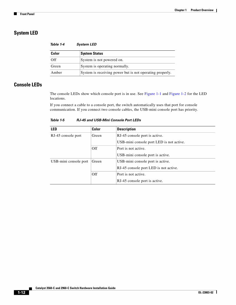
System LED
Console LEDs
The console LEDs show which console port is in use. See Figure 1-1 and Figure 1-2 for the LED locations.
If you connect a cable to a console port, the switch automatically uses that port for console communication. If you connect two console cables, the USB-mini console port has priority.
Table 1-4 System LED
Color System Status
Off System is not powered on.
Green System is operating normally.
Amber System is receiving power but is not operating properly.
Table 1-5 RJ-45 and USB-Mini Console Port LEDs
LED Color Description
RJ-45 console port Green RJ-45 console port is active.
USB-mini console port LED is not active.
Off Port is not active.
USB-mini console port is active.
USB-mini console port Green USB-mini console port is active.
RJ-45 console port LED is not active.
Off Port is not active.
RJ-45 console port is active.
1-12Catalyst 3560-C and 2960-C Switch Hardware Installation Guide
OL-23803-02
Chapter 1 Product OverviewFront Panel
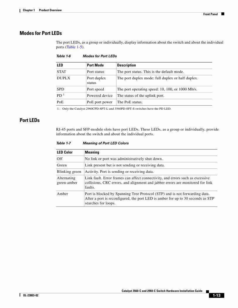
Modes for Port LEDs
The port LEDs, as a group or individually, display information about the switch and about the individual ports (Table 1-5).
Port LEDs
RJ-45 ports and SFP-module slots have port LEDs. These LEDs, as a group or individually, provide information about the switch and about the individual ports.
Table 1-6 Modes for Port LEDs
LED Port Mode Description
STAT Port status The port status. This is the default mode.
DUPLX Port duplex status
The port duplex mode: full duplex or half duplex.
SPD Port speed The port operating speed: 10, 100, or 1000 Mb/s.
PD 1
1. Only the Catalyst 2960CPD-8PT-L and 3560PD-8PT-S switches have the PD LED.
Powered device The status of the uplink port.
PoE PoE port power The PoE status.
Table 1-7 Meaning of Port LED Colors
LED Color Meaning
Off No link or port was administratively shut down.
Green Link present but is not sending or receiving data.
Blinking green Activity. Port is sending or receiving data.
Alternating green-amber
Link fault. Error frames can affect connectivity, and errors such as excessive collisions, CRC errors, and alignment and jabber errors are monitored for link faults.
Amber Port is blocked by Spanning Tree Protocol (STP) and is not forwarding data. After a port is reconfigured, the port LED is amber for up to 30 seconds as STP searches for loops.
1-13Catalyst 3560-C and 2960-C Switch Hardware Installation Guide
OL-23803-02
Chapter 1 Product OverviewFront Panel
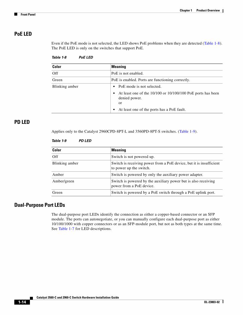
PoE LED
Even if the PoE mode is not selected, the LED shows PoE problems when they are detected (Table 1-8). The PoE LED is only on the switches that support PoE.
PD LED
Applies only to the Catalyst 2960CPD-8PT-L and 3560PD-8PT-S switches. (Table 1-9).
Dual-Purpose Port LEDs
The dual-purpose port LEDs identify the connection as either a copper-based connector or an SFP module. The ports can autonegotiate, or you can manually configure each dual-purpose port as either 10/100/1000 with copper connectors or as an SFP-module port, but not as both types at the same time. See Table 1-7 for LED descriptions.
Table 1-8 PoE LED
Color Meaning
Off PoE is not enabled.
Green PoE is enabled. Ports are functioning correctly.
Blinking amber • PoE mode is not selected.
• At least one of the 10/100 or 10/100/100 PoE ports has been denied power.or
• At least one of the ports has a PoE fault.
Table 1-9 PD LED
Color Meaning
Off Switch is not powered up.
Blinking amber Switch is receiving power from a PoE device, but it is insufficient to power up the switch.
Amber Switch is powered by only the auxiliary power adapter.
Amber/green Switch is powered by the auxiliary power but is also receiving power from a PoE device.
Green Switch is powered by a PoE switch through a PoE uplink port.
1-14Catalyst 3560-C and 2960-C Switch Hardware Installation Guide
OL-23803-02
Chapter 1 Product OverviewRear Panel
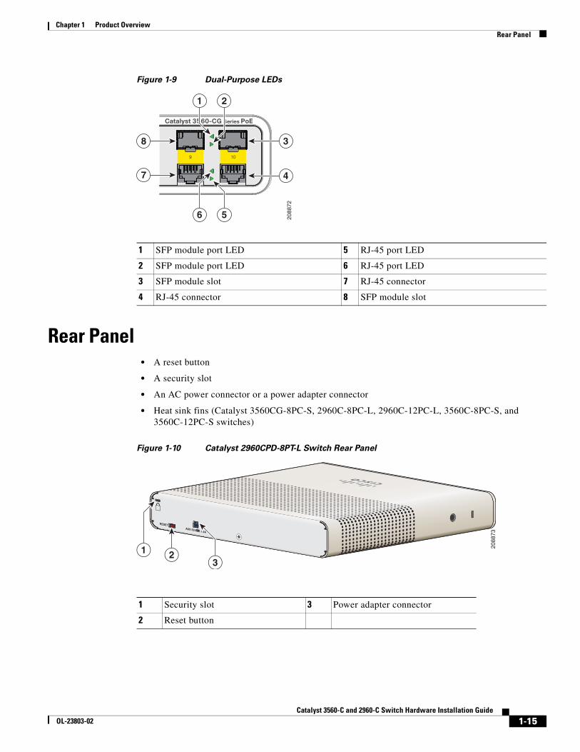
Figure 1-9 Dual-Purpose LEDs
Rear Panel • A reset button
• A security slot
• An AC power connector or a power adapter connector
• Heat sink fins (Catalyst 3560CG-8PC-S, 2960C-8PC-L, 2960C-12PC-L, 3560C-8PC-S, and 3560C-12PC-S switches)
Figure 1-10 Catalyst 2960CPD-8PT-L Switch Rear Panel
1 SFP module port LED 5 RJ-45 port LED
2 SFP module port LED 6 RJ-45 port LED
3 SFP module slot 7 RJ-45 connector
4 RJ-45 connector 8 SFP module slot
Catalyst 3560-CG Series PoE
9 10
38
7 4
1 2
6 5 2088
72
1 Security slot 3 Power adapter connector
2 Reset button
RESETAUX 53V , 1.5A
2
2088
73
13
1-15Catalyst 3560-C and 2960-C Switch Hardware Installation Guide
OL-23803-02
Chapter 1 Product OverviewRear Panel
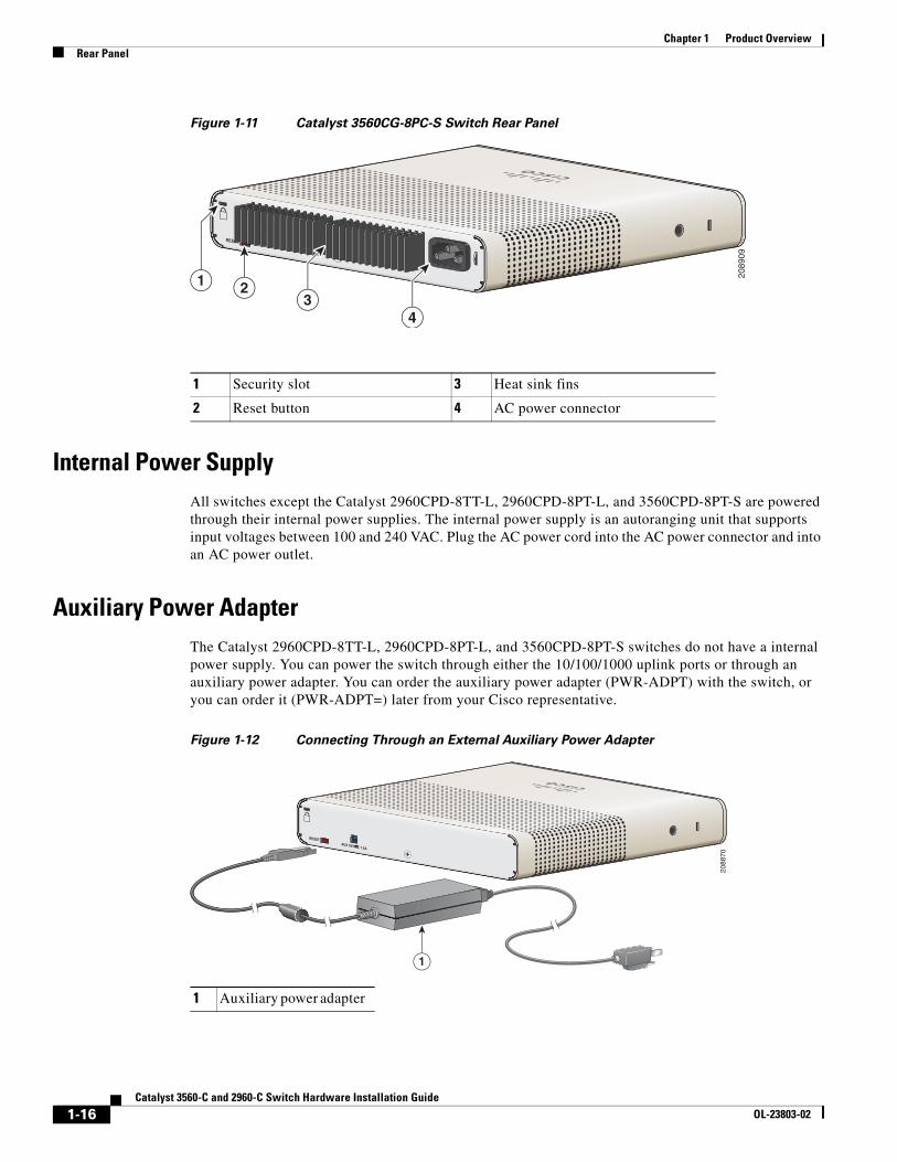
Figure 1-11 Catalyst 3560CG-8PC-S Switch Rear Panel
Internal Power SupplyAll switches except the Catalyst 2960CPD-8TT-L, 2960CPD-8PT-L, and 3560CPD-8PT-S are powered through their internal power supplies. The internal power supply is an autoranging unit that supports input voltages between 100 and 240 VAC. Plug the AC power cord into the AC power connector and into an AC power outlet.
Auxiliary Power AdapterThe Catalyst 2960CPD-8TT-L, 2960CPD-8PT-L, and 3560CPD-8PT-S switches do not have a internal power supply. You can power the switch through either the 10/100/1000 uplink ports or through an auxiliary power adapter. You can order the auxiliary power adapter (PWR-ADPT) with the switch, or you can order it (PWR-ADPT=) later from your Cisco representative.
Figure 1-12 Connecting Through an External Auxiliary Power Adapter
1 Security slot 3 Heat sink fins
2 Reset button 4 AC power connector
AUX 53V , 1.5A
RESET
2
2089
09
1
43
1 Auxiliary power adapter
RESETAUX 53V , 1.5A
1
2088
70
1-16Catalyst 3560-C and 2960-C Switch Hardware Installation Guide
OL-23803-02
Chapter 1 Product OverviewManagement Options
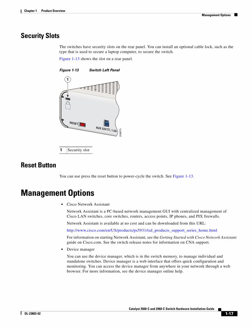
Security SlotsThe switches have security slots on the rear panel. You can install an optional cable lock, such as the type that is used to secure a laptop computer, to secure the switch.
Figure 1-13 shows the slot on a rear panel.
Figure 1-13 Switch Left Panel
Reset ButtonYou can use press the reset button to power-cycle the switch. See Figure 1-13.
Management Options• Cisco Network Assistant
Network Assistant is a PC-based network management GUI with centralized management of Cisco LAN switches, core switches, routers, access points, IP phones, and PIX firewalls.
Network Assistant is available at no cost and can be downloaded from this URL:
http://www.cisco.com/en/US/products/ps5931/tsd_products_support_series_home.html
For information on starting Network Assistant, see the Getting Started with Cisco Network Assistant guide on Cisco.com. See the switch release notes for information on CNA support.
• Device manager
You can use the device manager, which is in the switch memory, to manage individual and standalone switches. Device manager is a web interface that offers quick configuration and monitoring. You can access the device manager from anywhere in your network through a web browser. For more information, see the device manager online help.
1 Security slot
RESETAUX 53V , 1.5A
1
2088
75
1-17Catalyst 3560-C and 2960-C Switch Hardware Installation Guide
OL-23803-02
Chapter 1 Product OverviewNetwork Configurations
• Cisco IOS CLI
The switch CLI is based on Cisco IOS software and supports desktop-switching features. You can configure and monitor the switch and switch cluster members from the CLI. You can access the CLI either by connecting your management station directly to the switch console port or by using Telnet from a remote management station. See the switch command reference on Cisco.com for more information.
For setup instructions that use the CLI, go to Appendix C, “Configuring the Switch with the CLI Setup Program.”
• CiscoView application
The CiscoView device-management application displays the switch image that you can use to set configuration parameters and to view switch status and performance information. The CiscoView application, which you purchase separately, can be a standalone application or part of a Simple Network Management Protocol (SNMP) platform. See the CiscoView documentation for more information.
• SNMP network management
You can use SNMP management applications such as CiscoWorks LAN Management Solution (LMS) and HP OpenView to configure and manage the switch. You also can manage it from an SNMP-compatible workstation that is running platforms such as HP OpenView or SunNet Manager.
The Cisco Configuration Engine is a network management device that works with embedded CNS agents in the switch software. You can use the Cisco Configuration Engine to automate initial configurations and configuration updates on the switch.
Network ConfigurationsSee the switch software configuration guide on Cisco.com for an explanation of network configuration concepts. The software configuration guide also provides network configuration examples for creating dedicated network segments that are interconnected through Ethernet connections.
1-18Catalyst 3560-C and 2960-C Switch Hardware Installation Guide
OL-23803-02
Catalyst 356OL-23803-02
C H A P T E R 2
Switch InstallationThis chapter describes how to start your switch and how to interpret the power-on self-test (POST) that ensures proper operation. It also describes how to install the switch.
Read the topics and perform the procedures in this order:
• Preparing for Installation, page 2-1
• Verifying Switch Operation, page 2-5
• Mounting the Switch, page 2-5
• Installing a Cover for the Reset Button (Optional), page 2-24
• Installing the Power Cord Retainer (Optional), page 2-25
• Installing the Cable Guard (Optional), page 2-28
• Connecting Devices to the Ethernet Ports, page 2-33
Preparing for Installation• Warnings, page 2-1
• Installation Guidelines, page 2-3
• Equipment That You Supply, page 2-4
• Box Contents, page 2-4
• Powering the Switch, page 2-4
WarningsThese warnings are translated into several languages in the Regulatory Compliance and Safety Information for the Catalyst 3560-C and the 2960-C Switches guide.
Warning Before working on equipment that is connected to power lines, remove jewelry (including rings, necklaces, and watches). Metal objects will heat up when connected to power and ground and can cause serious burns or weld the metal object to the terminals. Statement 43
2-10-C and 2960-C Switch Hardware Installation Guide
Chapter 2 Switch InstallationPreparing for Installation
Warning Read the wall-mounting instructions carefully before beginning installation. Failure to use the correct hardware or to follow the correct procedures could result in a hazardous situation to people and damage to the system. Statement 378
Warning Do not work on the system or connect or disconnect cables during periods of lightning activity. Statement 1001
Warning Read the installation instructions before connecting the system to the power source. Statement 1004
Warning This product relies on the building’s installation for short-circuit (overcurrent) protection. Ensure that the protective device is rated not greater than: 20 A Statement 1005
Warning Class 1 laser product. Statement 1008
Warning This equipment must be grounded. Never defeat the ground conductor or operate the equipment in the absence of a suitably installed ground conductor. Contact the appropriate electrical inspection authority or an electrician if you are uncertain that suitable grounding is available. Statement 1024
Warning Ultimate disposal of this product should be handled according to all national laws and regulations. Statement 1040
Warning To prevent bodily injury when mounting or servicing this unit in a rack, you must take special precautions to ensure that the system remains stable. The following guidelines are provided to ensure your safety:
• This unit should be mounted at the bottom of the rack if it is the only unit in the rack.
• When mounting this unit in a partially filled rack, load the rack from the bottom to the top with the heaviest component at the bottom of the rack.
• If the rack is provided with stabilizing devices, install the stabilizers before mounting or servicing the unit in the rack. Statement 1006
2-2Catalyst 3560-C and 2960-C Switch Hardware Installation Guide
OL-23803-02
Chapter 2 Switch InstallationPreparing for Installation
Warning For connections outside the building where the equipment is installed, the following ports must be connected through an approved network termination unit with integral circuit protection: 10/100/1000 Ethernet. Statement 1044
Warning To prevent the system from overheating, do not operate it in an area that exceeds the maximum recommended ambient temperature of: 113°F (45°C) Statement 1047
Note For Catalyst 3560CG-8PC-S, 3560CG-8TC-S, and 2960CG-8TC-L switches, the maximum recommended ambient temperature is: 104°F (40°C).
Warning No user-serviceable parts inside. Do not open. Statement 1073
Warning Installation of the equipment must comply with local and national electrical codes. Statement 1074
Warning To prevent airflow restriction, allow clearance around the ventilation openings to be at least:3 in. (7.6 cm) Statement 1076
Warning Hot surface. Statement 1079
Note Applies to the Catalyst 3560CG-8PC-S switch.
Installation GuidelinesBefore installing the switch, these guidelines must be met:
• The operating environment must be within the ranges listed in Appendix A, “Technical Specifications.”
• Cabling is away from sources of electrical noise, such as radios, power lines, and fluorescent lighting fixtures. Make sure that the cabling is away from other devices that might damage the cables.
• Airflow around the switch and through the vents must be unrestricted. We strongly recommend that you allow at least 3 in. (7.6 cm) of clearance from the left, right, and top sides of the switch to avoid any flow blockage. If you are installing the switch in a rack, allow at least 1.75 in. (4 cm) of empty rack space above each switch.
• Catalyst 3560CG-8PC-S, 2960C-8PC-L, 2960C-12PC-L, 3560C-8PC-S, and 3560C-12PC-S switches: Allow at least 1.75 in. (4 cm) clearance from the ends of the external heat sink fins.
2-3Catalyst 3560-C and 2960-C Switch Hardware Installation Guide
OL-23803-02
Chapter 2 Switch InstallationPowering the Switch
• Temperature around the unit does not exceed 113°F (45°C).
If the switch is installed in a closed environment or in a multirack assembly, the temperature around it might be greater than normal room temperature.
• Humidity around the switch must not exceed 95 percent.
• Altitude at the installation site must not be greater than 10,000 feet (3,049 meters).
• Do not place any items on the top of the switch.
• Do not wall-mount the switch with its front panel facing up. Following safety regulations, wall-mount the switch with its front panel facing down or to the side to prevent airflow restriction and to provide easier access to the cables.
• Clearance to the switch front and rear panels meets these conditions:
– You can easily read the front-panel LEDs.
– Access to ports is sufficient for unrestricted cabling.
– The AC power cord can reach from the AC power outlet to the connector on the switch rear panel.
• For 10/100 and 10/100/1000 fixed ports, cable lengths from the switch to connected devices are not more than 328 feet (100 meters).
• For cable lengths for small form-factor pluggable (SFP)-module connections, see the “SFP Module Connectors” section on page B-2 and the module documentation.
Equipment That You SupplyYou might need this equipment to install the switch:
• Number-2 Phillips screwdriver
• Drill with a #27 drill bit (0.144-inch [3.7 mm])
Box ContentsThe switch getting started guide on Cisco.com describes the box contents. If any item is missing or damaged, contact your Cisco representative or reseller for support.
Powering the SwitchBefore installing the switch in a rack, on a desk, a shelf, or a wall, you should power on the switch and verify that it passes POST.
Power the switch:
Catalyst 2960CPD-8PT-L and 2960CPD-8TT-L
• Connect a 10/100/1000 uplink port to a PoE or PoE+ switch, such as a Catalyst 3750-X.
Or
• Plug the auxiliary power adapter cord into the switch AUX power connector and into an AC power outlet.
2-4Catalyst 3560-C and 2960-C Switch Hardware Installation Guide
OL-23803-02
Chapter 2 Switch InstallationVerifying Switch Operation
Note You can use both the uplink port and the auxiliary power adapter. However, the auxiliary power input takes precedence.
Catalyst 3560CPD-8PT-S
• Connect a 10/100/1000 uplink port to a PoE+ switch, such as a Catalyst 3750-X.
Or
• Plug the auxiliary power adapter cord into the switch AUX power connector and into an AC power outlet.
Note You can use both the uplink port and the auxiliary power adapter. However, the auxiliary power input takes precedence.
All models (except the Catalyst 2960CPD-8PT-L, 2960CPD-8TT-L, and 3560CPD-8PT-S)
• Plug the AC power cord to the switch AC power connector and into an AC power outlet.
Verifying Switch OperationAs the switch powers on, it begins the POST, a series of tests that runs automatically to ensure that the switch functions properly. LEDs blink during the test, which lasts approximately 1 minute. When the switch begins POST, the System, Status, Duplex, and Speed LEDs turn green. The System LED blinks green, and the other LEDs remain green.
When the POST completes successfully, the System LED turns green. The other LEDs turn off and then reflect the switch operating status. If a switch fails POST, the System LED turns amber.
POST failures are usually fatal. Call Cisco technical support representative if your switch fails POST.
After a successful POST, unplug the power cord from the switch. Mount the switch in a rack on a desk or shelf, under a desk or shelf, or on a wall, as described in the “Mounting the Switch” section on page 2-5.
Mounting the Switch• On a Desk or Shelf (without Mounting Screws)
• Desk, Shelf, or Wall (with Mounting Screws)
• With a Mounting Tray
• In a Rack
• On a DIN Rail
2-5Catalyst 3560-C and 2960-C Switch Hardware Installation Guide
OL-23803-02
Chapter 2 Switch InstallationMounting the Switch
On a Desk or Shelf (without Mounting Screws)
Step 1 Locate the adhesive strip with the rubber feet in the accessory kit.
Step 2 Remove the four rubber feet from the adhesive strip, and attach them to the recessed areas on the bottom of the unit. This prevents the switch from sliding on the desk or shelf.
Note We strongly recommend that you attach the rubber feet. Doing so helps prevent airflow restriction and overheating.
Step 3 Place the switch on the desk or shelf.
Warning To prevent airflow restriction, allow clearance around the ventilation openings to be at least:3 in. (7.6 cm) Statement 1076
After you mount the switch, see the “After Installing the Switch” section on page 2-31 for information about the switch configuration.
Desk, Shelf, or Wall (with Mounting Screws)You can use the mounting screws to mount the switch:
• On a desk or a shelf
• Under a desk or a shelf
• On a wall
Desk- or Shelf-Mounting
Step 1 Use the screw template to align the mounting screw holes and also as a guide to make sure that you install the screws into the desk or shelf with proper clearance.
Step 2 Position the screw template on top of the desk or shelf so that the two side-by-side slots face the front of the desk or shelf, as shown in Figure 2-1. This ensures that the power cord faces the rear of the desk or shelf after the switch is installed.
Note Wait before you attach the screw template to the desk or shelf.
2-6Catalyst 3560-C and 2960-C Switch Hardware Installation Guide
OL-23803-02
Chapter 2 Switch InstallationMounting the Switch
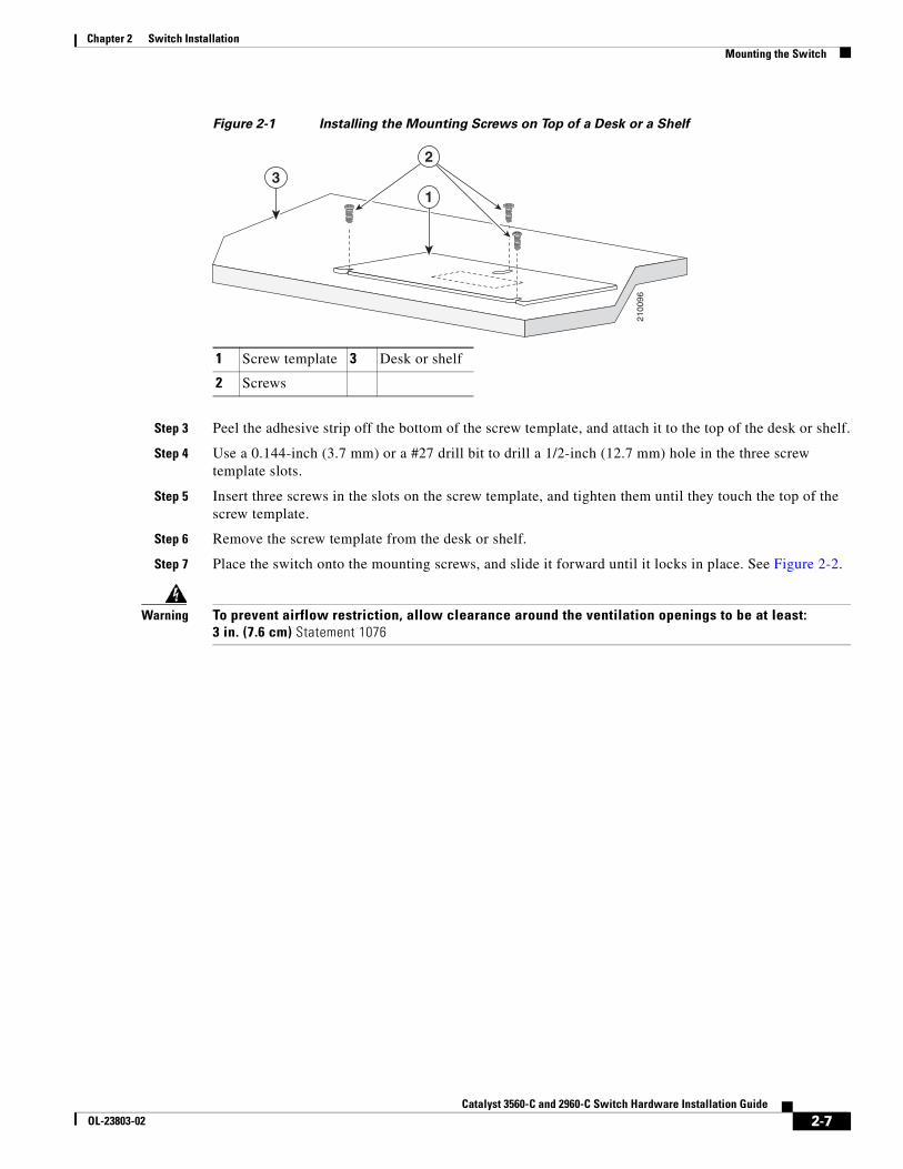
Figure 2-1 Installing the Mounting Screws on Top of a Desk or a Shelf
Step 3 Peel the adhesive strip off the bottom of the screw template, and attach it to the top of the desk or shelf.
Step 4 Use a 0.144-inch (3.7 mm) or a #27 drill bit to drill a 1/2-inch (12.7 mm) hole in the three screw template slots.
Step 5 Insert three screws in the slots on the screw template, and tighten them until they touch the top of the screw template.
Step 6 Remove the screw template from the desk or shelf.
Step 7 Place the switch onto the mounting screws, and slide it forward until it locks in place. See Figure 2-2.
Warning To prevent airflow restriction, allow clearance around the ventilation openings to be at least:3 in. (7.6 cm) Statement 1076
1 Screw template 3 Desk or shelf
2 Screws
13
2
2100
96
2-7Catalyst 3560-C and 2960-C Switch Hardware Installation Guide
OL-23803-02
Chapter 2 Switch InstallationMounting the Switch
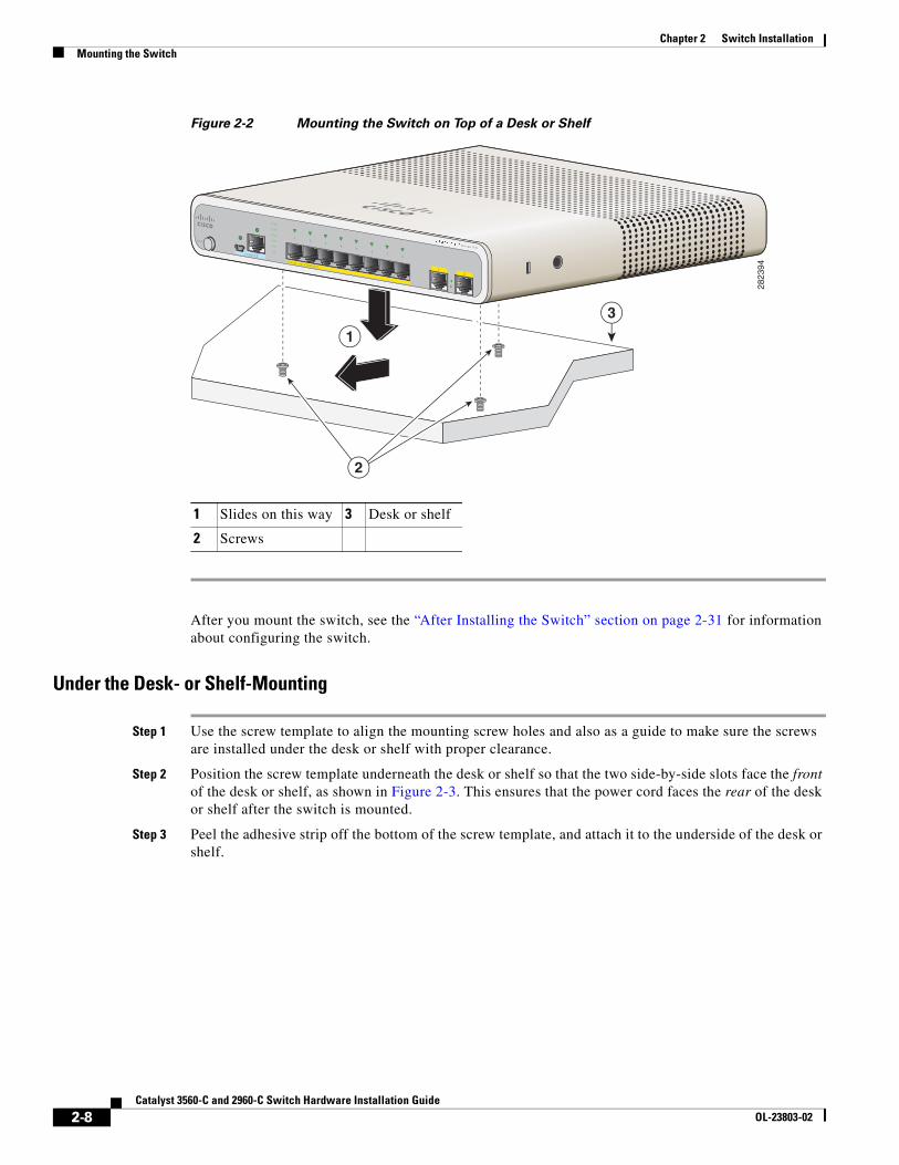
Figure 2-2 Mounting the Switch on Top of a Desk or Shelf
After you mount the switch, see the “After Installing the Switch” section on page 2-31 for information about configuring the switch.
Under the Desk- or Shelf-Mounting
Step 1 Use the screw template to align the mounting screw holes and also as a guide to make sure the screws are installed under the desk or shelf with proper clearance.
Step 2 Position the screw template underneath the desk or shelf so that the two side-by-side slots face the front of the desk or shelf, as shown in Figure 2-3. This ensures that the power cord faces the rear of the desk or shelf after the switch is mounted.
Step 3 Peel the adhesive strip off the bottom of the screw template, and attach it to the underside of the desk or shelf.
1 Slides on this way 3 Desk or shelf
2 Screws
3
2
1
M O DE
CO NSO LE
12
SeriesPD
PO W ER OVER ETHERNET
12
34
56
78
PD
SPD
PoE
DPLX
STAT
SYST
2823
94
2-8Catalyst 3560-C and 2960-C Switch Hardware Installation Guide
OL-23803-02
Chapter 2 Switch InstallationMounting the Switch
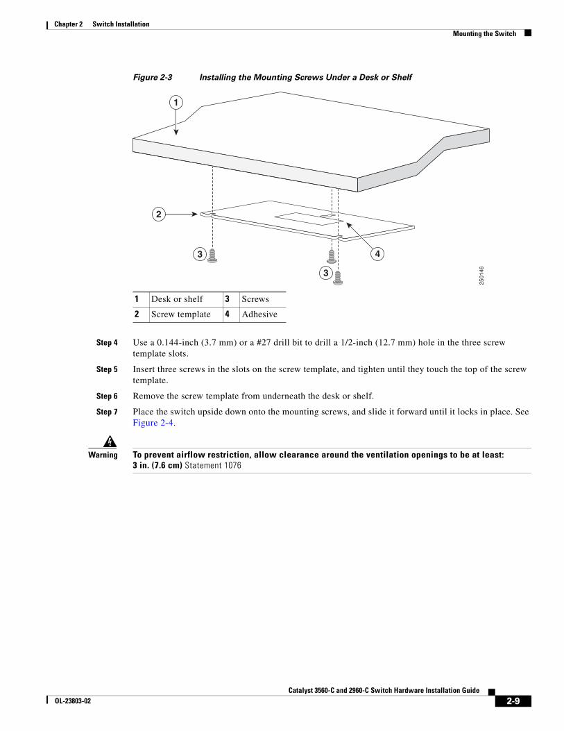
Figure 2-3 Installing the Mounting Screws Under a Desk or Shelf
Step 4 Use a 0.144-inch (3.7 mm) or a #27 drill bit to drill a 1/2-inch (12.7 mm) hole in the three screw template slots.
Step 5 Insert three screws in the slots on the screw template, and tighten until they touch the top of the screw template.
Step 6 Remove the screw template from underneath the desk or shelf.
Step 7 Place the switch upside down onto the mounting screws, and slide it forward until it locks in place. See Figure 2-4.
Warning To prevent airflow restriction, allow clearance around the ventilation openings to be at least:3 in. (7.6 cm) Statement 1076
1 Desk or shelf 3 Screws
2 Screw template 4 Adhesive
1
4
2
3
3
2501
46
2-9Catalyst 3560-C and 2960-C Switch Hardware Installation Guide
OL-23803-02
Chapter 2 Switch InstallationMounting the Switch
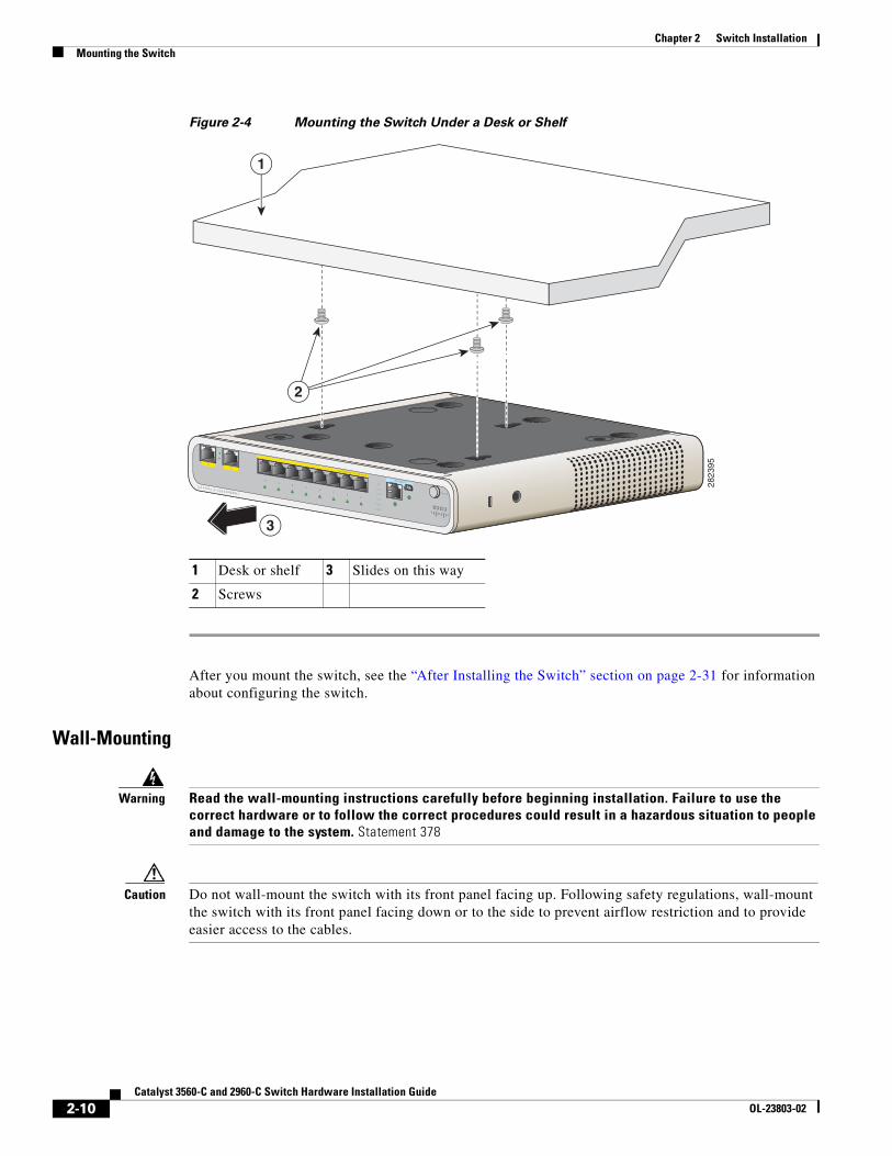
Figure 2-4 Mounting the Switch Under a Desk or Shelf
After you mount the switch, see the “After Installing the Switch” section on page 2-31 for information about configuring the switch.
Wall-Mounting
Warning Read the wall-mounting instructions carefully before beginning installation. Failure to use the correct hardware or to follow the correct procedures could result in a hazardous situation to people and damage to the system. Statement 378
Caution Do not wall-mount the switch with its front panel facing up. Following safety regulations, wall-mount the switch with its front panel facing down or to the side to prevent airflow restriction and to provide easier access to the cables.
1 Desk or shelf 3 Slides on this way
2 Screws
MODE
PD
SPD
PoE
DPLX
STAT
SYST
Catalyst 2960-
C Series PD
12
34
56
78
21
CONSOLE
POWER OVERETHER
NET
3
1
2823
95
2
2-10Catalyst 3560-C and 2960-C Switch Hardware Installation Guide
OL-23803-02
Chapter 2 Switch InstallationMounting the Switch
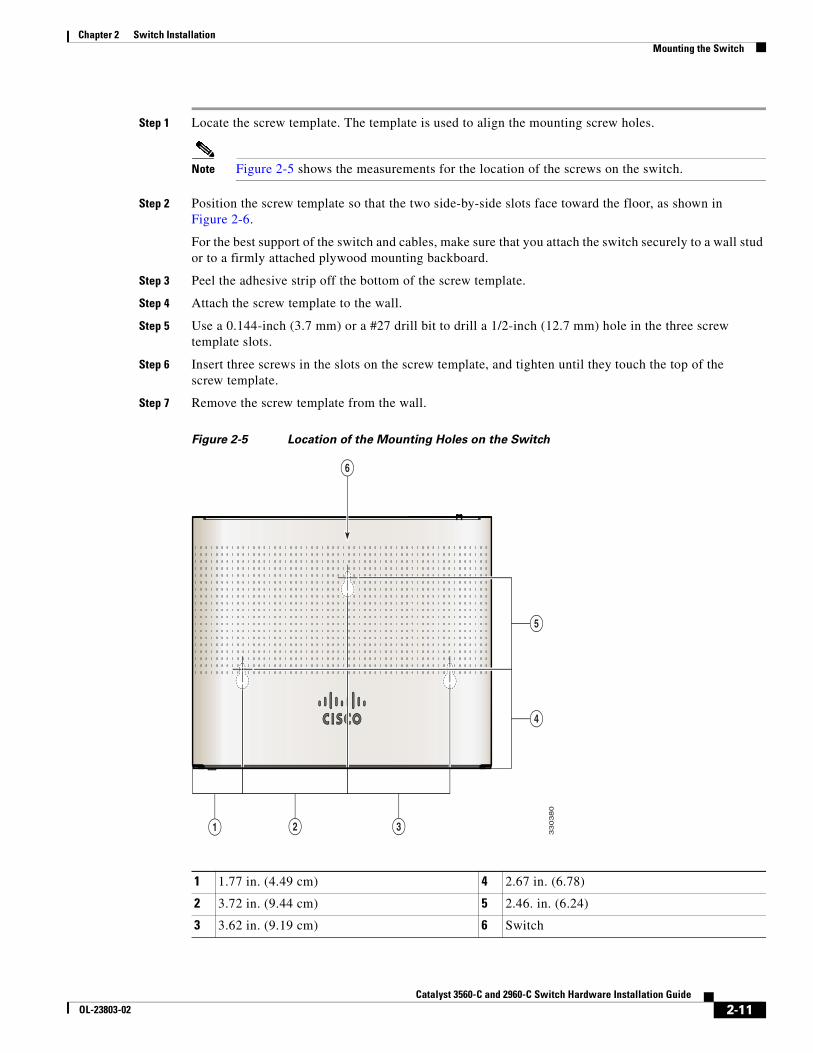
Step 1 Locate the screw template. The template is used to align the mounting screw holes.
Note Figure 2-5 shows the measurements for the location of the screws on the switch.
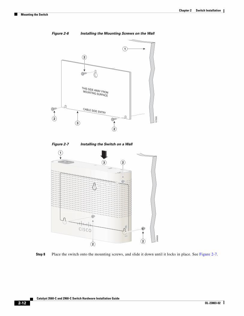
Step 2 Position the screw template so that the two side-by-side slots face toward the floor, as shown in Figure 2-6.
For the best support of the switch and cables, make sure that you attach the switch securely to a wall stud or to a firmly attached plywood mounting backboard.
Step 3 Peel the adhesive strip off the bottom of the screw template.
Step 4 Attach the screw template to the wall.
Step 5 Use a 0.144-inch (3.7 mm) or a #27 drill bit to drill a 1/2-inch (12.7 mm) hole in the three screw template slots.
Step 6 Insert three screws in the slots on the screw template, and tighten until they touch the top of the screw template.
Step 7 Remove the screw template from the wall.
Figure 2-5 Location of the Mounting Holes on the Switch
1 1.77 in. (4.49 cm) 4 2.67 in. (6.78)
2 3.72 in. (9.44 cm) 5 2.46. in. (6.24)
3 3.62 in. (9.19 cm) 6 Switch
5
1 2
4
3
33
03
80
6
2-11Catalyst 3560-C and 2960-C Switch Hardware Installation Guide
OL-23803-02
Chapter 2 Switch InstallationMounting the Switch
Figure 2-6 Installing the Mounting Screws on the Wall
Figure 2-7 Installing the Switch on a Wall
Step 8 Place the switch onto the mounting screws, and slide it down until it locks in place. See Figure 2-7.
CABLE SIDE ENTRY
THIS SIDE AWAY FROM MOUNTING SURFACE
2
32
2
1
1578
28
RESETAUX 53V , 1.5A
3
1
22
2
2089
26
2-12Catalyst 3560-C and 2960-C Switch Hardware Installation Guide
OL-23803-02
Chapter 2 Switch InstallationMounting the Switch
With a Mounting TrayThe mounting kit (part number CMP-MGNT-TRAY=) is optional. You can order it when you order your switch, or you can order it later from your Cisco representative.
The mounting kit ships contents:
• Two number-10 Phillips pan-head screws
• Three number-8 Phillips pan-head screws
• Mounting tray
• Magnet
You can use the mounting tray by itself with mounting screws, or with a magnet.
Mounting Tray with Screws
You can use the mounting tray to secure the switch:
• On a desk or shelf
• Under a desk or shelf
• On a wall
Caution Do not wall-mount the switch with its front panel facing up. Following safety regulations, wall-mount the switch with its front panel facing down or to the side, to allow sufficient airflow and to provide easier access to the cables.
This example shows you how to mount the switch on a desk or shelf. You can use a similar procedure to mount the switch under a desk or on a wall.
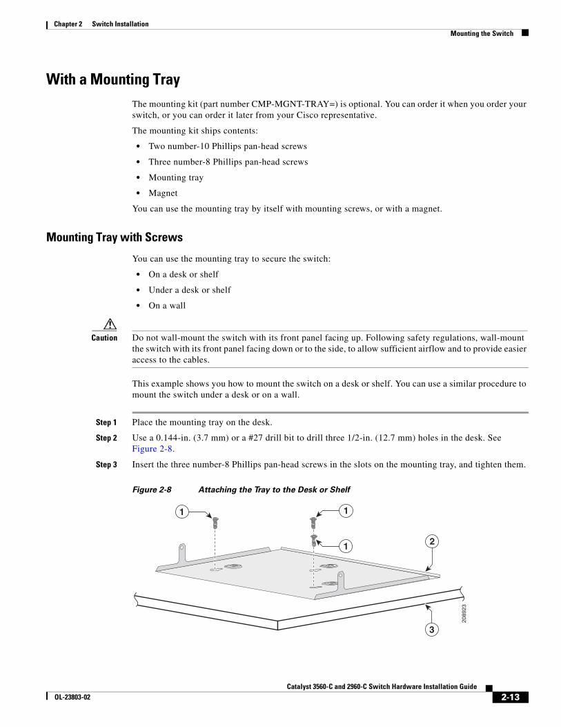
Step 1 Place the mounting tray on the desk.
Step 2 Use a 0.144-in. (3.7 mm) or a #27 drill bit to drill three 1/2-in. (12.7 mm) holes in the desk. See Figure 2-8.
Step 3 Insert the three number-8 Phillips pan-head screws in the slots on the mounting tray, and tighten them.
Figure 2-8 Attaching the Tray to the Desk or Shelf
3
21
1 1
2089
23
2-13Catalyst 3560-C and 2960-C Switch Hardware Installation Guide
OL-23803-02
Chapter 2 Switch InstallationMounting the Switch
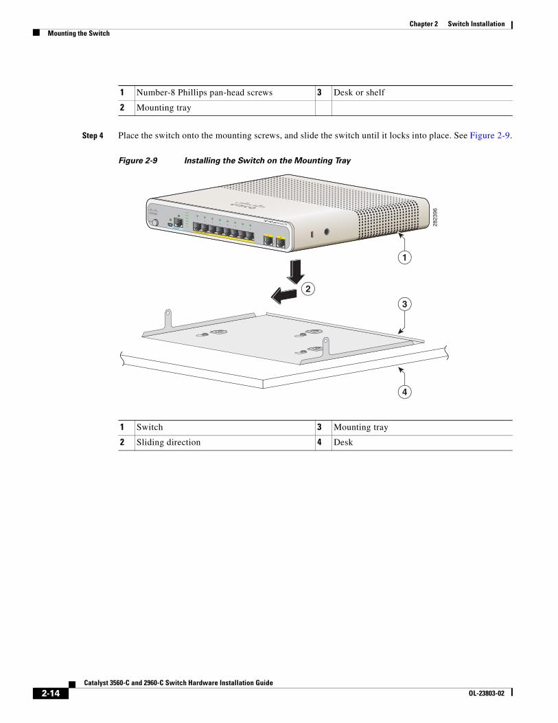
Step 4 Place the switch onto the mounting screws, and slide the switch until it locks into place. See Figure 2-9.
Figure 2-9 Installing the Switch on the Mounting Tray
1 Number-8 Phillips pan-head screws 3 Desk or shelf
2 Mounting tray
1 Switch 3 Mounting tray
2 Sliding direction 4 Desk
MODE
CONSOLE
12
Series PD
POWER OVER ETHERNET
12
34
56
78
PD
SPD
PoE
DPLX
STAT
SYST
2823
96
1
4
3
2
2-14Catalyst 3560-C and 2960-C Switch Hardware Installation Guide
OL-23803-02
Chapter 2 Switch InstallationMounting the Switch
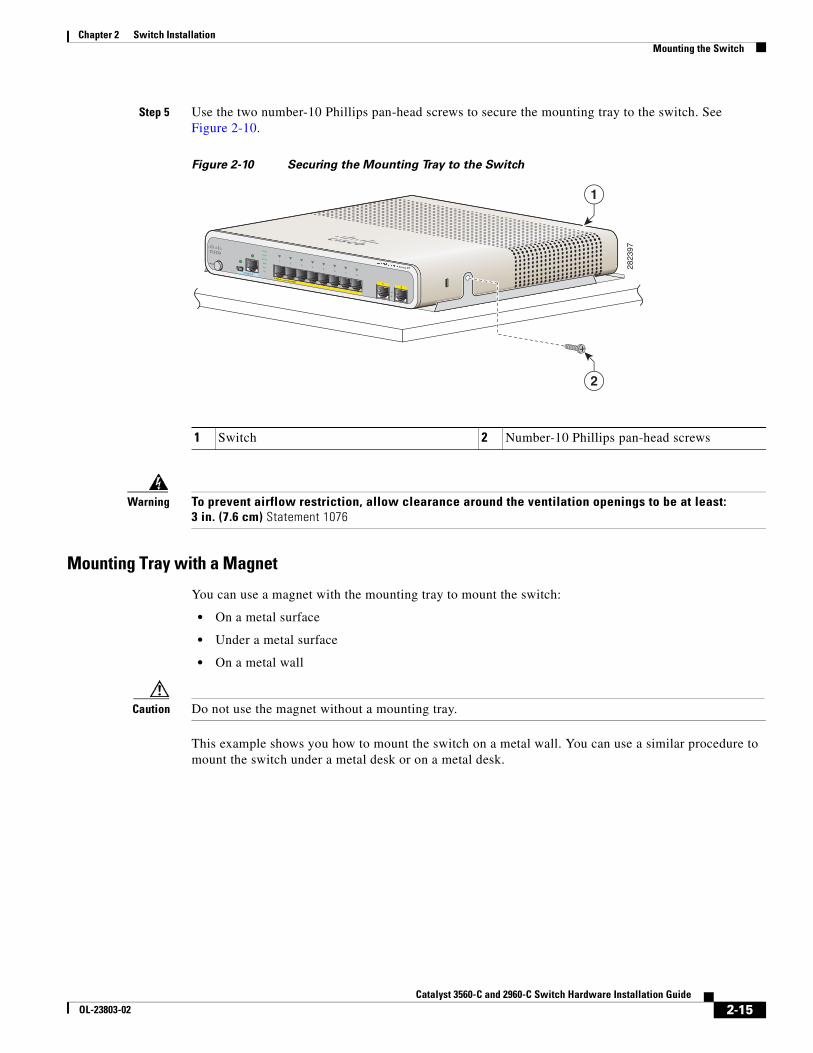
Step 5 Use the two number-10 Phillips pan-head screws to secure the mounting tray to the switch. See Figure 2-10.
Figure 2-10 Securing the Mounting Tray to the Switch
Warning To prevent airflow restriction, allow clearance around the ventilation openings to be at least:3 in. (7.6 cm) Statement 1076
Mounting Tray with a Magnet
You can use a magnet with the mounting tray to mount the switch:
• On a metal surface
• Under a metal surface
• On a metal wall
Caution Do not use the magnet without a mounting tray.
This example shows you how to mount the switch on a metal wall. You can use a similar procedure to mount the switch under a metal desk or on a metal desk.
1 Switch 2 Number-10 Phillips pan-head screws
MODE
CONSOLE
12
Series PD
POWER OVER ETHERNET
12
34
56
78
PD
SPD
PoE
DPLX
STAT
SYST
2823
97
2
1
2-15Catalyst 3560-C and 2960-C Switch Hardware Installation Guide
OL-23803-02
Chapter 2 Switch InstallationMounting the Switch
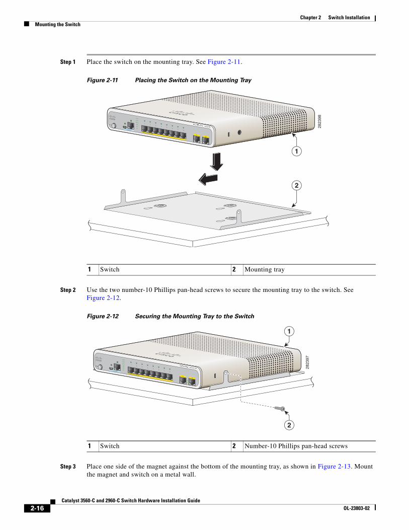
Step 1 Place the switch on the mounting tray. See Figure 2-11.
Figure 2-11 Placing the Switch on the Mounting Tray
Step 2 Use the two number-10 Phillips pan-head screws to secure the mounting tray to the switch. See Figure 2-12.
Figure 2-12 Securing the Mounting Tray to the Switch
Step 3 Place one side of the magnet against the bottom of the mounting tray, as shown in Figure 2-13. Mount the magnet and switch on a metal wall.
1 Switch 2 Mounting tray
MODE
CONSOLE
12
Series PD
POWER OVER ETHERNET
12
34
56
78
PD
SPD
PoE
DPLX
STAT
SYST
2823
98
1
2
1 Switch 2 Number-10 Phillips pan-head screws
MODE
CONSOLE
12
Series PD
POWER OVER ETHERNET
12
34
56
78
PD
SPD
PoE
DPLX
STAT
SYST
2823
97
2
1
2-16Catalyst 3560-C and 2960-C Switch Hardware Installation Guide
OL-23803-02
Chapter 2 Switch InstallationMounting the Switch
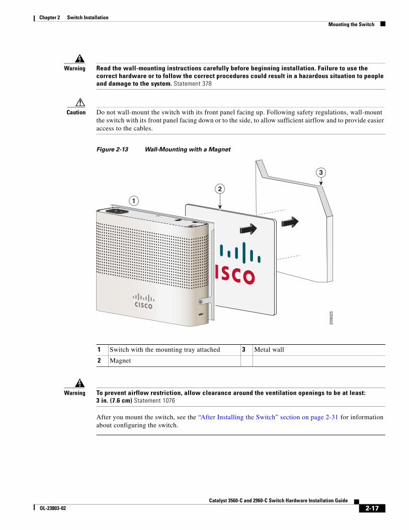
Warning Read the wall-mounting instructions carefully before beginning installation. Failure to use the correct hardware or to follow the correct procedures could result in a hazardous situation to people and damage to the system. Statement 378
Caution Do not wall-mount the switch with its front panel facing up. Following safety regulations, wall-mount the switch with its front panel facing down or to the side, to allow sufficient airflow and to provide easier access to the cables.
Figure 2-13 Wall-Mounting with a Magnet
Warning To prevent airflow restriction, allow clearance around the ventilation openings to be at least:3 in. (7.6 cm) Statement 1076
After you mount the switch, see the “After Installing the Switch” section on page 2-31 for information about configuring the switch.
1 Switch with the mounting tray attached 3 Metal wall
2 Magnet
2090
25
RESETAUX 53V , 1.5A
3
2
1
2-17Catalyst 3560-C and 2960-C Switch Hardware Installation Guide
OL-23803-02
Chapter 2 Switch InstallationMounting the Switch
In a Rack Installing the switch in a rack requires an optional bracket kit that is not included with the switch. You can order these kits from your Cisco representative:
• 19-inch rack-mounting brackets (RCKMNT-19-CMPCT=)
• 23- and 24-inch rack-mounting brackets (RCKMNT-23-CMPCT=)
To install the switch in a rack, follow the instructions described in these sections:
• Attaching Brackets to the Switch, page 2-18
• Mounting the Switch in a Rack, page 2-19
Attaching Brackets to the Switch
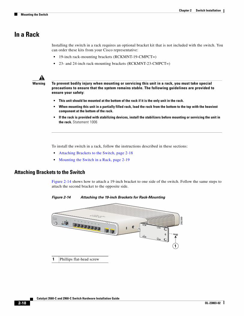
Figure 2-14 shows how to attach a 19-inch bracket to one side of the switch. Follow the same steps to attach the second bracket to the opposite side.
Figure 2-14 Attaching the 19-inch Brackets for Rack-Mounting
Warning To prevent bodily injury when mounting or servicing this unit in a rack, you must take special precautions to ensure that the system remains stable. The following guidelines are provided to ensure your safety:
• This unit should be mounted at the bottom of the rack if it is the only unit in the rack.
• When mounting this unit in a partially filled rack, load the rack from the bottom to the top with the heaviest component at the bottom of the rack.
• If the rack is provided with stabilizing devices, install the stabilizers before mounting or servicing the unit in the rack. Statement 1006
1 Phillips flat-head screw
M O DE
CO NSO LE
12
SeriesPD
PO W ER OVER ETHERNET
12
34
56
78
PD
SPD
PoE
DPLX
STAT
SYST
2823
99
1
2-18Catalyst 3560-C and 2960-C Switch Hardware Installation Guide
OL-23803-02
Chapter 2 Switch InstallationMounting the Switch
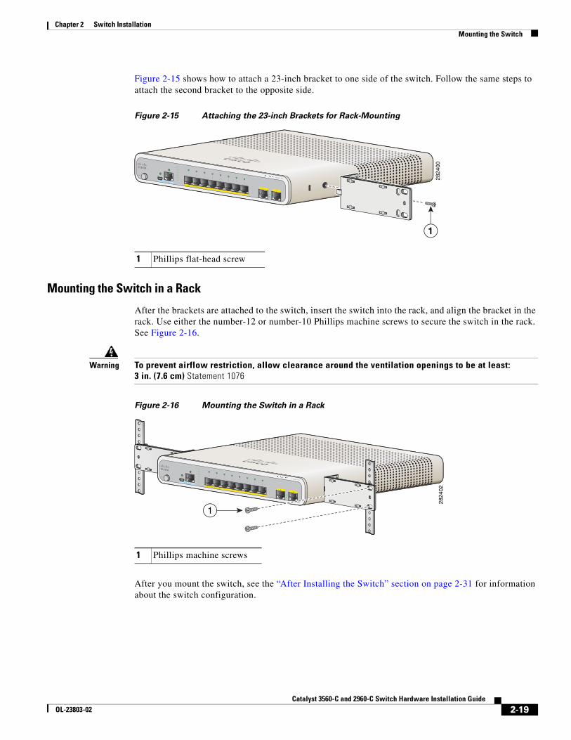
Figure 2-15 shows how to attach a 23-inch bracket to one side of the switch. Follow the same steps to attach the second bracket to the opposite side.
Figure 2-15 Attaching the 23-inch Brackets for Rack-Mounting
Mounting the Switch in a Rack
After the brackets are attached to the switch, insert the switch into the rack, and align the bracket in the rack. Use either the number-12 or number-10 Phillips machine screws to secure the switch in the rack. See Figure 2-16.
Warning To prevent airflow restriction, allow clearance around the ventilation openings to be at least:3 in. (7.6 cm) Statement 1076
Figure 2-16 Mounting the Switch in a Rack
After you mount the switch, see the “After Installing the Switch” section on page 2-31 for information about the switch configuration.
1 Phillips flat-head screw
M O DE
CO NSO LE
12
SeriesPD
PO W ER OVER ETHERNET
12
34
56
78
PD
SPD
PoE
DPLX
STAT
SYST
2824
00
1
1 Phillips machine screws
M O DE
CO NSO LE
12
Series PD
PO W ER OVER ETHERNET
12
34
56
78
PD
SPD
PoE
DPLX
STAT
SYST
2824
02
1
2-19Catalyst 3560-C and 2960-C Switch Hardware Installation Guide
OL-23803-02
Chapter 2 Switch InstallationMounting the Switch
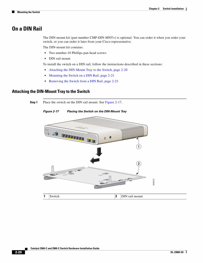
On a DIN RailThe DIN-mount kit (part number CMP-DIN-MNT=) is optional. You can order it when you order your switch, or you can order it later from your Cisco representative.
The DIN-mount kit contains:
• Two number-10 Phillips pan-head screws
• DIN rail mount
To install the switch on a DIN rail, follow the instructions described in these sections:
• Attaching the DIN-Mount Tray to the Switch, page 2-20
• Mounting the Switch on a DIN Rail, page 2-21
• Removing the Switch from a DIN Rail, page 2-23
Attaching the DIN-Mount Tray to the Switch
Step 1 Place the switch on the DIN rail mount. See Figure 2-17.
Figure 2-17 Placing the Switch on the DIN-Mount Tray
1 Switch 2 DIN rail mount
MODE
CONSOLE
12
Series PD
POWER OVER ETHERNET
12
34
56
78
PD
SPD
PoE
DPLX
STAT
SYST
3442
12
1
2
2-20Catalyst 3560-C and 2960-C Switch Hardware Installation Guide
OL-23803-02
Chapter 2 Switch InstallationMounting the Switch
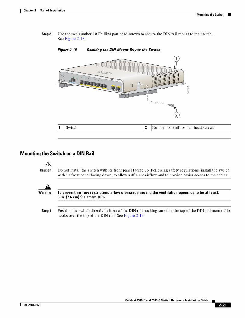
Step 2 Use the two number-10 Phillips pan-head screws to secure the DIN rail mount to the switch. See Figure 2-18.
Figure 2-18 Securing the DIN-Mount Tray to the Switch
Mounting the Switch on a DIN Rail
Caution Do not install the switch with its front panel facing up. Following safety regulations, install the switch with its front panel facing down, to allow sufficient airflow and to provide easier access to the cables.
Warning To prevent airflow restriction, allow clearance around the ventilation openings to be at least:3 in. (7.6 cm) Statement 1076
Step 1 Position the switch directly in front of the DIN rail, making sure that the top of the DIN rail mount clip hooks over the top of the DIN rail. See Figure 2-19.
1 Switch 2 Number-10 Phillips pan-head screws
MODE
CONSOLE
12
Series PD
POWER OVER ETHERNET
12
34
56
78
PD
SPD
PoE
DPLX
STAT
SYST
3442
13
2
1
2-21Catalyst 3560-C and 2960-C Switch Hardware Installation Guide
OL-23803-02
Chapter 2 Switch InstallationMounting the Switch
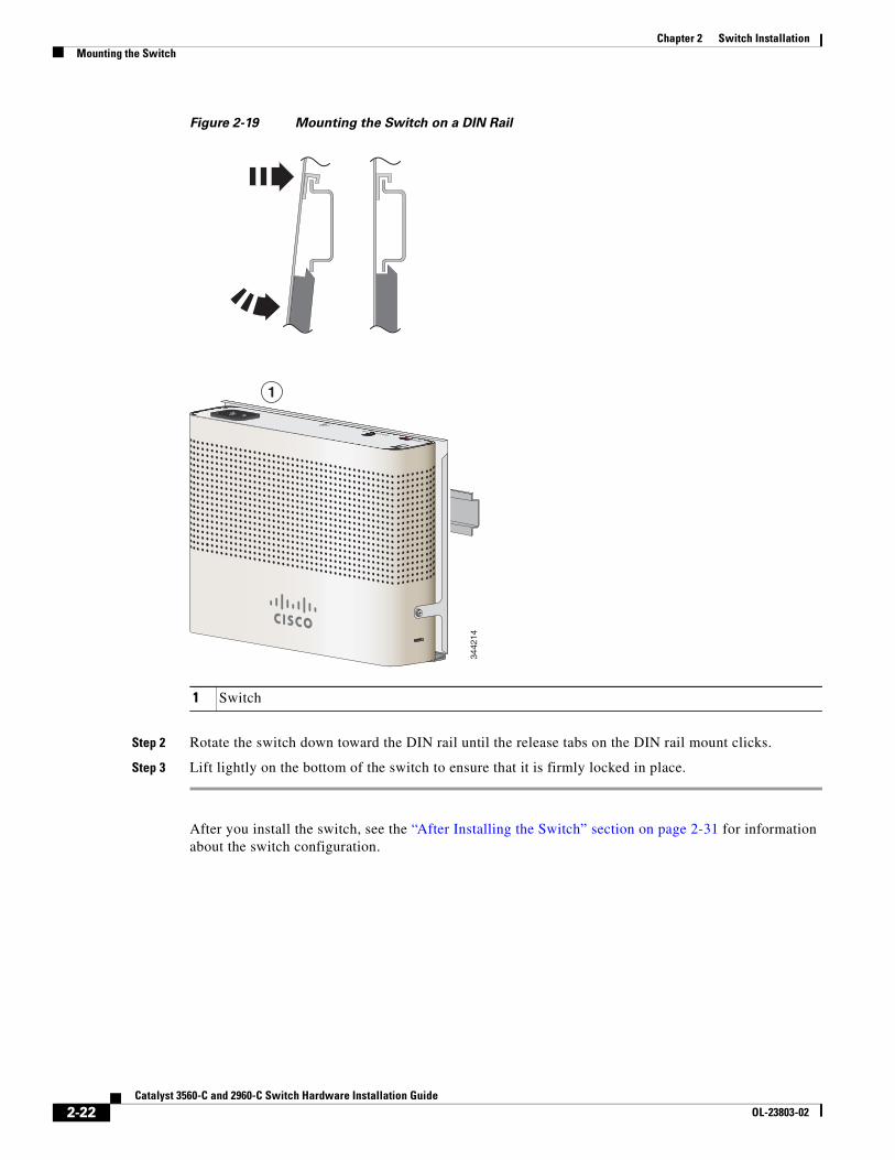
Figure 2-19 Mounting the Switch on a DIN Rail
Step 2 Rotate the switch down toward the DIN rail until the release tabs on the DIN rail mount clicks.
Step 3 Lift lightly on the bottom of the switch to ensure that it is firmly locked in place.
After you install the switch, see the “After Installing the Switch” section on page 2-31 for information about the switch configuration.
1 Switch
1
3442
14
RESETAUX 53V , 1.5A
2-22Catalyst 3560-C and 2960-C Switch Hardware Installation Guide
OL-23803-02
Chapter 2 Switch InstallationMounting the Switch
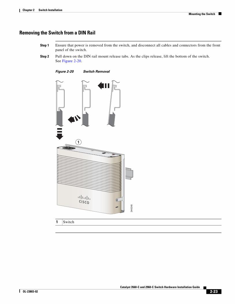
Removing the Switch from a DIN Rail
Step 1 Ensure that power is removed from the switch, and disconnect all cables and connectors from the front panel of the switch.
Step 2 Pull down on the DIN rail mount release tabs. As the clips release, lift the bottom of the switch. See Figure 2-20.
Figure 2-20 Switch Removal
1 Switch
1
3442
46
RESETAUX 53V , 1.5A
2-23Catalyst 3560-C and 2960-C Switch Hardware Installation Guide
OL-23803-02
Chapter 2 Switch InstallationInstalling a Cover for the Reset Button (Optional)
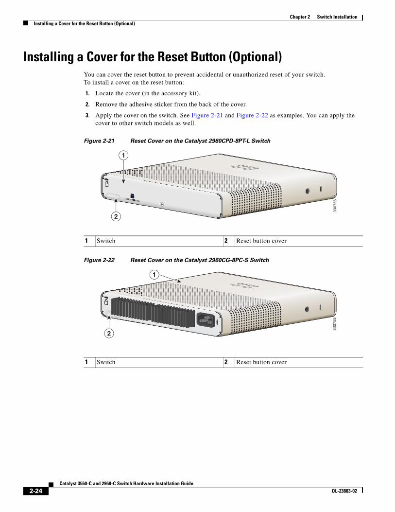
Installing a Cover for the Reset Button (Optional)You can cover the reset button to prevent accidental or unauthorized reset of your switch. To install a cover on the reset button:
1. Locate the cover (in the accessory kit).
2. Remove the adhesive sticker from the back of the cover.
3. Apply the cover on the switch. See Figure 2-21 and Figure 2-22 as examples. You can apply the cover to other switch models as well.
Figure 2-21 Reset Cover on the Catalyst 2960CPD-8PT-L Switch
Figure 2-22 Reset Cover on the Catalyst 2960CG-8PC-S Switch
1 Switch 2 Reset button cover
RESETAUX 53V , 1.5A
RESETRESETAUX 53V , 1.5A
2
3307
56
1
1 Switch 2 Reset button cover
RESETRRRRRRESETESETRESETR ETT
233
0755
1
2-24Catalyst 3560-C and 2960-C Switch Hardware Installation Guide
OL-23803-02
Chapter 2 Switch InstallationInstalling the Power Cord Retainer (Optional)
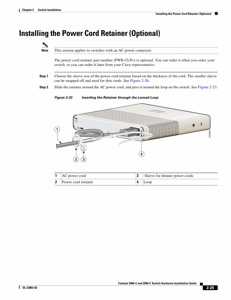
Installing the Power Cord Retainer (Optional)
Note This section applies to switches with an AC power connector.
The power cord retainer part number (PWR-CLP=) is optional. You can order it when you order your switch, or you can order it later from your Cisco representative.
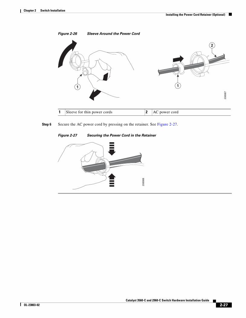
Step 1 Choose the sleeve size of the power cord retainer based on the thickness of the cord. The smaller sleeve can be snapped off and used for thin cords. See Figure 2-26.
Step 2 Slide the retainer around the AC power cord, and pass it around the loop on the switch. See Figure 2-23.
Figure 2-23 Inserting the Retainer through the Lanced Loop
1 AC power cord 3 Sleeve for thinner power cords
2 Power cord retainer 4 Loop
RESET1
324
2089
84
2-25Catalyst 3560-C and 2960-C Switch Hardware Installation Guide
OL-23803-02
Chapter 2 Switch InstallationInstalling the Power Cord Retainer (Optional)
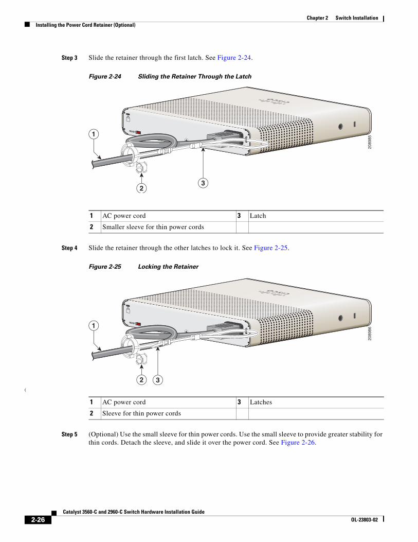
Step 3 Slide the retainer through the first latch. See Figure 2-24.
Figure 2-24 Sliding the Retainer Through the Latch
Step 4 Slide the retainer through the other latches to lock it. See Figure 2-25.
Figure 2-25 Locking the Retainer
(
Step 5 (Optional) Use the small sleeve for thin power cords. Use the small sleeve to provide greater stability for thin cords. Detach the sleeve, and slide it over the power cord. See Figure 2-26.
1 AC power cord 3 Latch
2 Smaller sleeve for thin power cords
RESET1
23
2089
85
1 AC power cord 3 Latches
2 Sleeve for thin power cords
RESET1
2 3
2089
86
2-26Catalyst 3560-C and 2960-C Switch Hardware Installation Guide
OL-23803-02
Chapter 2 Switch InstallationInstalling the Power Cord Retainer (Optional)
Figure 2-26 Sleeve Around the Power Cord
Step 6 Secure the AC power cord by pressing on the retainer. See Figure 2-27.
Figure 2-27 Securing the Power Cord in the Retainer
1 Sleeve for thin power cords 2 AC power cord
1
2
1
2089
87
2089
88
2-27Catalyst 3560-C and 2960-C Switch Hardware Installation Guide
OL-23803-02
Chapter 2 Switch InstallationInstalling the Cable Guard (Optional)
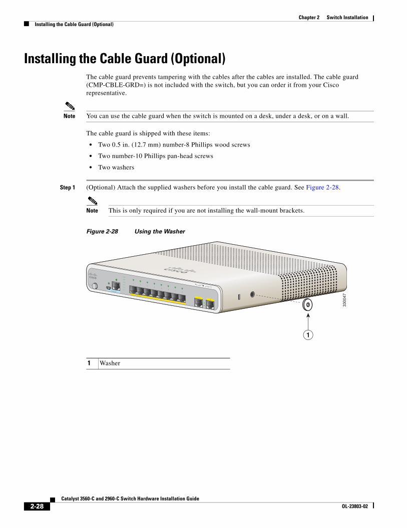
Installing the Cable Guard (Optional)The cable guard prevents tampering with the cables after the cables are installed. The cable guard (CMP-CBLE-GRD=) is not included with the switch, but you can order it from your Cisco representative.
Note You can use the cable guard when the switch is mounted on a desk, under a desk, or on a wall.
The cable guard is shipped with these items:
• Two 0.5 in. (12.7 mm) number-8 Phillips wood screws
• Two number-10 Phillips pan-head screws
• Two washers
Step 1 (Optional) Attach the supplied washers before you install the cable guard. See Figure 2-28.
Note This is only required if you are not installing the wall-mount brackets.
Figure 2-28 Using the Washer
1 Washer
M ODE
CONSOLE
12
SeriesPD
POW EROVER ETHERNET
12
34
56
78
PD
SPD
PoE
DPLX
STAT
SYST
3300
47
1
2-28Catalyst 3560-C and 2960-C Switch Hardware Installation Guide
OL-23803-02
Chapter 2 Switch InstallationInstalling the Cable Guard (Optional)
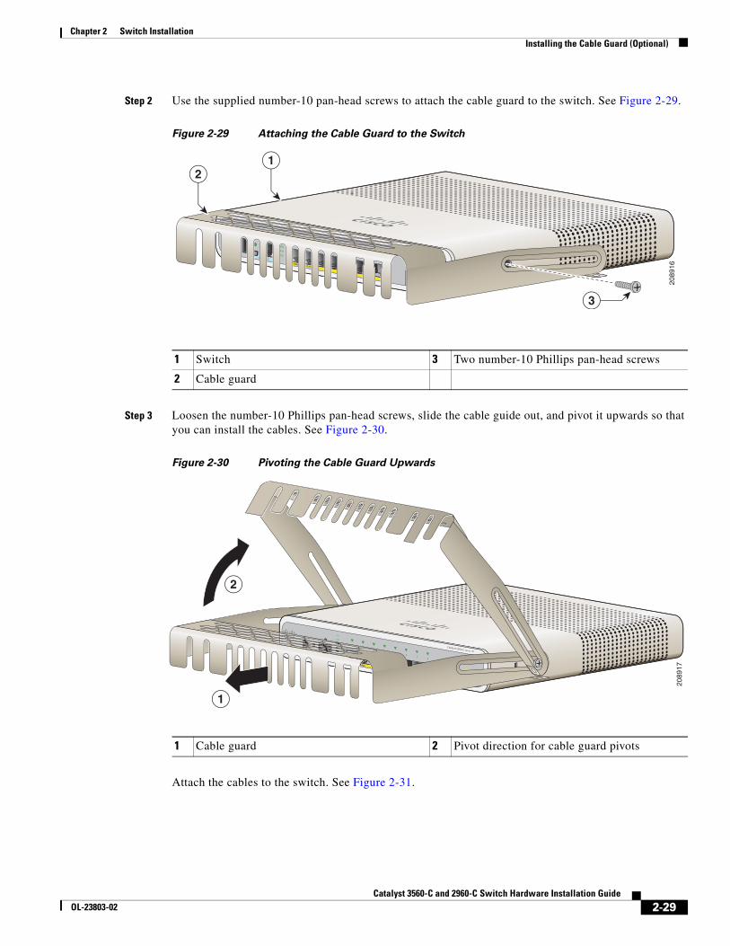
Step 2 Use the supplied number-10 pan-head screws to attach the cable guard to the switch. See Figure 2-29.
Figure 2-29 Attaching the Cable Guard to the Switch
Step 3 Loosen the number-10 Phillips pan-head screws, slide the cable guide out, and pivot it upwards so that you can install the cables. See Figure 2-30.
Figure 2-30 Pivoting the Cable Guard Upwards
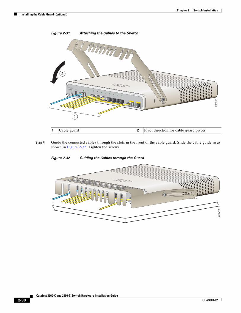
Attach the cables to the switch. See Figure 2-31.
1 Switch 3 Two number-10 Phillips pan-head screws
2 Cable guard
MODE
CONSOLE
12
Catalyst 2960-C Series PD
POWER OVER ETHERNET
12
34
56
78
PD
SPD
PoE
DPLX
STAT
SYST
2089
16
21
3
1 Cable guard 2 Pivot direction for cable guard pivots
CONSOLE
12
Catalyst 2960-C Series PD
12
34
56
78
PD
STAT
SYST
12
34
5
2089
17
1
2
2-29Catalyst 3560-C and 2960-C Switch Hardware Installation Guide
OL-23803-02
Chapter 2 Switch InstallationInstalling the Cable Guard (Optional)
Figure 2-31 Attaching the Cables to the Switch
Step 4 Guide the connected cables through the slots in the front of the cable guard. Slide the cable guide in as shown in Figure 2-33. Tighten the screws.
Figure 2-32 Guiding the Cables through the Guard
1 Cable guard 2 Pivot direction for cable guard pivots
MODE
CONSOLE
12
Catalyst 2960-C Series PD
POWER OVER ETHERNET
12
34
56
78
PD
SPD
PoE
DPLX
STAT
SYST
2089
18
1
2
3300
40
2-30Catalyst 3560-C and 2960-C Switch Hardware Installation Guide
OL-23803-02
Chapter 2 Switch InstallationAfter Installing the Switch
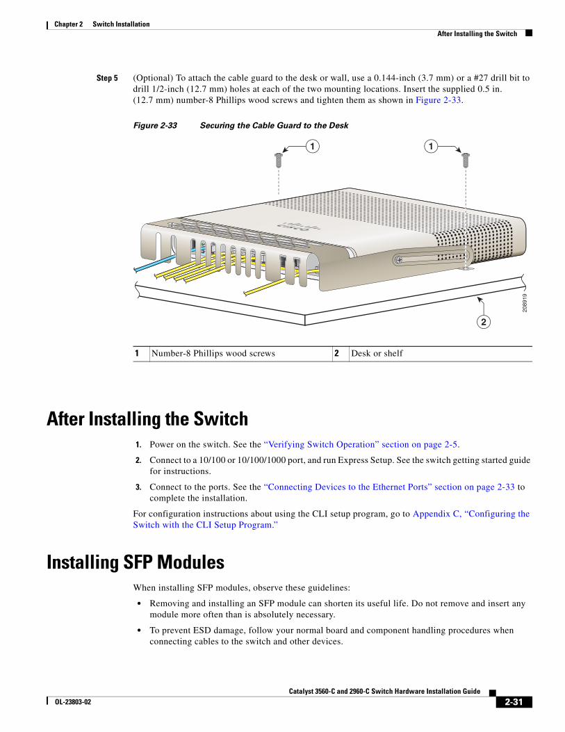
Step 5 (Optional) To attach the cable guard to the desk or wall, use a 0.144-inch (3.7 mm) or a #27 drill bit to drill 1/2-inch (12.7 mm) holes at each of the two mounting locations. Insert the supplied 0.5 in. (12.7 mm) number-8 Phillips wood screws and tighten them as shown in Figure 2-33.
Figure 2-33 Securing the Cable Guard to the Desk
After Installing the Switch1. Power on the switch. See the “Verifying Switch Operation” section on page 2-5.
2. Connect to a 10/100 or 10/100/1000 port, and run Express Setup. See the switch getting started guide for instructions.
3. Connect to the ports. See the “Connecting Devices to the Ethernet Ports” section on page 2-33 to complete the installation.
For configuration instructions about using the CLI setup program, go to Appendix C, “Configuring the Switch with the CLI Setup Program.”
Installing SFP ModulesWhen installing SFP modules, observe these guidelines:
• Removing and installing an SFP module can shorten its useful life. Do not remove and insert any module more often than is absolutely necessary.
• To prevent ESD damage, follow your normal board and component handling procedures when connecting cables to the switch and other devices.
1 Number-8 Phillips wood screws 2 Desk or shelf
2089
19
2
11
2-31Catalyst 3560-C and 2960-C Switch Hardware Installation Guide
OL-23803-02
Chapter 2 Switch InstallationRemoving SFP Modules
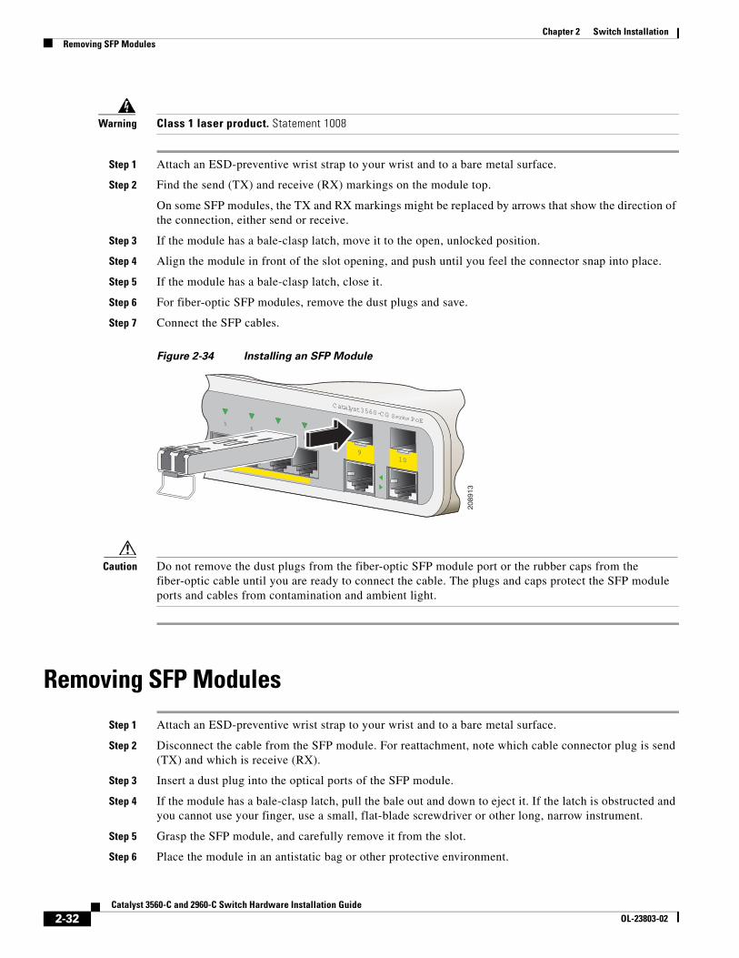
Warning Class 1 laser product. Statement 1008
Step 1 Attach an ESD-preventive wrist strap to your wrist and to a bare metal surface.
Step 2 Find the send (TX) and receive (RX) markings on the module top.
On some SFP modules, the TX and RX markings might be replaced by arrows that show the direction of the connection, either send or receive.
Step 3 If the module has a bale-clasp latch, move it to the open, unlocked position.
Step 4 Align the module in front of the slot opening, and push until you feel the connector snap into place.
Step 5 If the module has a bale-clasp latch, close it.
Step 6 For fiber-optic SFP modules, remove the dust plugs and save.
Step 7 Connect the SFP cables.
Figure 2-34 Installing an SFP Module
Caution Do not remove the dust plugs from the fiber-optic SFP module port or the rubber caps from the fiber-optic cable until you are ready to connect the cable. The plugs and caps protect the SFP module ports and cables from contamination and ambient light.
Removing SFP Modules
Step 1 Attach an ESD-preventive wrist strap to your wrist and to a bare metal surface.
Step 2 Disconnect the cable from the SFP module. For reattachment, note which cable connector plug is send (TX) and which is receive (RX).
Step 3 Insert a dust plug into the optical ports of the SFP module.
Step 4 If the module has a bale-clasp latch, pull the bale out and down to eject it. If the latch is obstructed and you cannot use your finger, use a small, flat-blade screwdriver or other long, narrow instrument.
Step 5 Grasp the SFP module, and carefully remove it from the slot.
Step 6 Place the module in an antistatic bag or other protective environment.
9
Catalyst 3560-CG Series PoE56
78
10
2089
13
2-32Catalyst 3560-C and 2960-C Switch Hardware Installation Guide
OL-23803-02
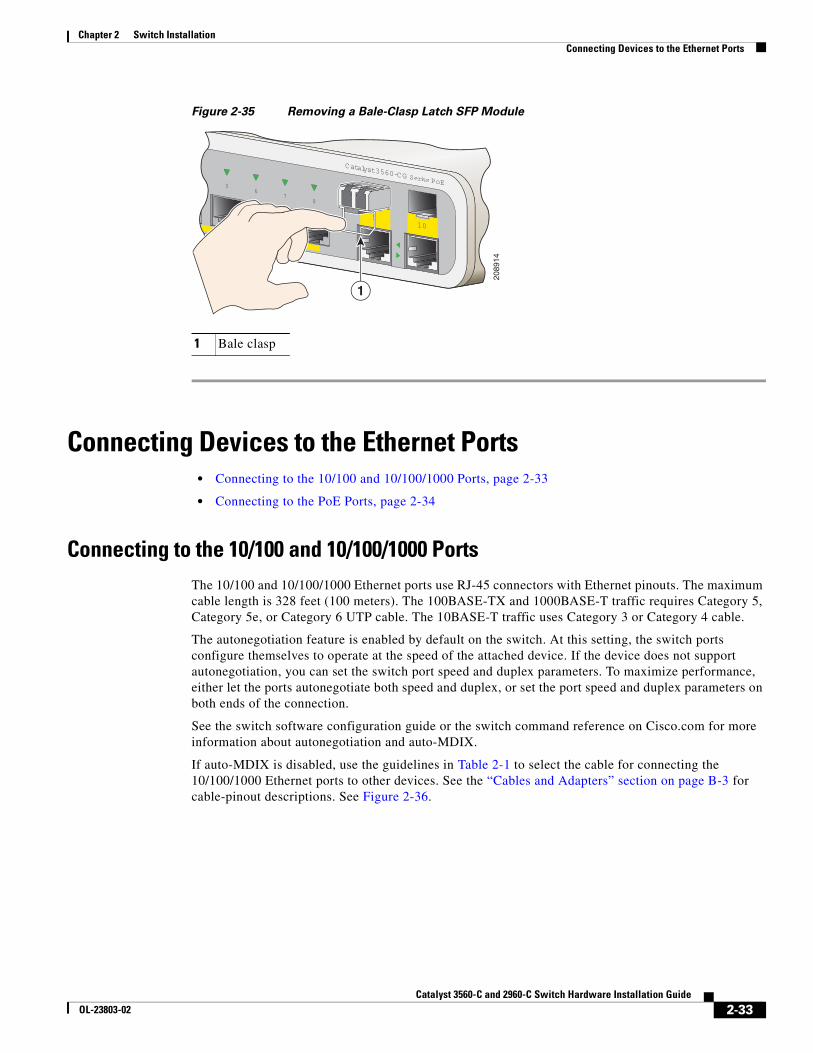
Chapter 2 Switch InstallationConnecting Devices to the Ethernet Ports
Figure 2-35 Removing a Bale-Clasp Latch SFP Module
Connecting Devices to the Ethernet Ports• Connecting to the 10/100 and 10/100/1000 Ports, page 2-33
• Connecting to the PoE Ports, page 2-34
Connecting to the 10/100 and 10/100/1000 PortsThe 10/100 and 10/100/1000 Ethernet ports use RJ-45 connectors with Ethernet pinouts. The maximum cable length is 328 feet (100 meters). The 100BASE-TX and 1000BASE-T traffic requires Category 5, Category 5e, or Category 6 UTP cable. The 10BASE-T traffic uses Category 3 or Category 4 cable.
The autonegotiation feature is enabled by default on the switch. At this setting, the switch ports configure themselves to operate at the speed of the attached device. If the device does not support autonegotiation, you can set the switch port speed and duplex parameters. To maximize performance, either let the ports autonegotiate both speed and duplex, or set the port speed and duplex parameters on both ends of the connection.
See the switch software configuration guide or the switch command reference on Cisco.com for more information about autonegotiation and auto-MDIX.
If auto-MDIX is disabled, use the guidelines in Table 2-1 to select the cable for connecting the 10/100/1000 Ethernet ports to other devices. See the “Cables and Adapters” section on page B-3 for cable-pinout descriptions. See Figure 2-36.
1 Bale clasp
9
Catalyst 3560-CG Series PoE56
78
10
2089
14
1
2-33Catalyst 3560-C and 2960-C Switch Hardware Installation Guide
OL-23803-02
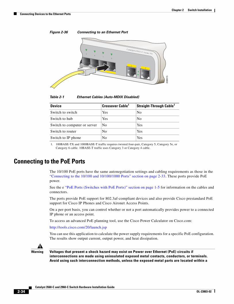
Chapter 2 Switch InstallationConnecting Devices to the Ethernet Ports
Figure 2-36 Connecting to an Ethernet Port
Connecting to the PoE PortsThe 10/100 PoE ports have the same autonegotiation settings and cabling requirements as those in the “Connecting to the 10/100 and 10/100/1000 Ports” section on page 2-33. These ports provide PoE power.
See the e “PoE Ports (Switches with PoE Ports)” section on page 1-5 for information on the cables and connectors.
The ports provide PoE support for 802.3af-compliant devices and also provide Cisco prestandard PoE support for Cisco IP Phones and Cisco Aironet Access Points.
On a per-port basis, you can control whether or not a port automatically provides power to a connected IP phone or an access point.
To access an advanced PoE planning tool, use the Cisco Power Calculator on Cisco.com:
http://tools.cisco.com/20/launch.jsp
You can use this application to calculate the power supply requirements for a specific PoE configuration. The results show output current, output power, and heat dissipation.
Warning Voltages that present a shock hazard may exist on Power over Ethernet (PoE) circuits if interconnections are made using uninsulated exposed metal contacts, conductors, or terminals. Avoid using such interconnection methods, unless the exposed metal parts are located within a
Table 2-1 Ethernet Cables (Auto-MDIX Disabled)
Device Crossover Cable1
1. 100BASE-TX and 1000BASE-T traffic requires twisted four-pair, Category 5, Category 5e, or Category 6 cable. 10BASE-T traffic uses Category 3 or Category 4 cable.
Straight-Through Cable1
Switch to switch Yes No
Switch to hub Yes No
Switch to computer or server No Yes
Switch to router No Yes
Switch to IP phone No Yes
12
Catalyst 2960-C Series PD56
78
2089
15
2-34Catalyst 3560-C and 2960-C Switch Hardware Installation Guide
OL-23803-02
Chapter 2 Switch InstallationWhere to Go Next
restricted access location and users and service people who are authorized within the restricted access location are made aware of the hazard. A restricted access area can be accessed only through the use of a special tool, lock and key or other means of security. Statement 1072
Caution Category 5e and Category 6 cables can store high levels of static electricity. Always ground the cables to a suitable and safe earth ground before connecting them to the switch or other devices.
Where to Go NextTo change the switch settings, you can use the switch default configuration or use any of the management options described in the “Management Options”section.
2-35Catalyst 3560-C and 2960-C Switch Hardware Installation Guide
OL-23803-02

Chapter 2 Switch InstallationWhere to Go Next
2-36Catalyst 3560-C and 2960-C Switch Hardware Installation Guide
OL-23803-02
Catalyst 356OL-23803-02
C H A P T E R 3
Troubleshooting• Diagnosing Problems, page 3-1
• Resetting the Switch, page 3-5
• Finding the Switch Serial Number, page 3-5
Diagnosing ProblemsThe switch LEDs provide troubleshooting information about the switch. They show POST failures, port-connectivity problems, and overall switch performance. You can also get statistics from the device manager, the CLI, or an SNMP workstation. See the software configuration guide, the switch command reference guide on Cisco.com, or the documentation that came with your SNMP application for details.
Switch POST ResultsSee the “Verifying Switch Operation” section on page 2-5 for information on POST.
Note POST failures are usually fatal. Contact your Cisco technical support representative if your switch does not pass POST.
3-10-C and 2960-C Switch Hardware Installation Guide
Chapter 3 TroubleshootingDiagnosing Problems
Switch LEDsLook at the port LEDs information when troubleshooting the switch. See the “LEDs” section on page 1-11 for a description of the LED colors and their meanings.
Switch Connections
Bad or Damaged Cable
Always examine the cable for marginal damage or failure. A cable might be just good enough to connect at the physical layer, but it could corrupt packets as a result of subtle damage to the wiring or connectors. You can identify this problem because the port has many packet errors or it constantly flaps (loses and regains link).
• Exchange the copper or fiber-optic cable with a known good cable.
• Look for broken or missing pins on cable connectors.
• Rule out any bad patch panel connections or media convertors between the source and the destination. If possible, bypass the patch panel, or eliminate media convertors (fiber-optic-to-copper).
• Try the cable in another port to see if the problem follows the cable.
Ethernet and Fiber-Optic Cables
Make sure that you have the correct cable:
• For Ethernet, use Category 3 copper cable for 10 Mb/s UTP connections. Use either Category 5, Category 5e, or Category 6 UTP for 10/100 or 10/100/1000 Mb/s connections.
• Verify that you have the correct fiber-optic cable for the distance and port type. Make sure that the connected device ports match and use the same type encoding, optical frequency, and fiber type.
• Determine if a copper crossover cable was used when a straight-through was required or the reverse. Enable auto-MDIX on the switch, or replace the cable. See Table 2-1 for recommended Ethernet cables.
Link Status
Verify that both sides have link. A broken wire or a shutdown port can cause one side to show link even though the other side does not have link.
A port LED that is on does not guarantee that the cable is functional. It might have encountered physical stress, causing it to function at a marginal level. If the port LED does not turn on:
• Connect the cable from the switch to a known good device.
• Make sure that both ends of the cable are connected to the correct ports.
• Verify that both devices have power.
• Verify that you are using the correct cable type. See Appendix B, “Connector and Cable Specifications” for information.
• Look for loose connections. Sometimes a cable appears to be seated but is not. Disconnect the cable, and then reconnect it.
3-2Catalyst 3560-C and 2960-C Switch Hardware Installation Guide
OL-23803-02
Chapter 3 TroubleshootingDiagnosing Problems
10/100 and 10/100/1000 Port Connections
A port appears to malfunction:
• Verify the status of all ports. See Table 1-7 on page 1-13 for descriptions of the LEDs and their meanings.
• Use the show interfaces privileged EXEC command to see if the port is error-disabled, disabled, or shut down. Re-enable the port if necessary.
• Verify the cable type. See Appendix B, “Connector and Cable Specifications.”
10/100 PoE or PoE+ Port Connections
A powered device connected to a PoE or PoE+ port does not receive power:
• Verify the status of all the ports. See Table 1-7 for descriptions of the LEDs and their meanings.
• Use the show interfaces privileged EXEC command to see if the port is error-disabled, disabled, or shutdown. Re-enable the port if necessary.
• Verify the cable type. Many legacy powered devices, including older Cisco IP phones and access points that do not fully support 802.3af might not support PoE when connected to the switch by a crossover cable. Replace the crossover cable with a straight-through cable.
Caution Noncompliant cabling or powered devices can cause a PoE port fault. Use only compliant cabling to connect Cisco prestandard IP Phones, and wireless access points, or 802.3af-compliant devices.
SFP Module
Use only Cisco SFP modules. Each Cisco module has an internal serial EEPROM that is encoded with security information. This encoding verifies that the module meets the requirements for the switch.
• Inspect the SFP module. Exchange the suspect module with a known good module.
• Verify that the module is supported on this platform. (The switch release notes on Cisco.com list the SFP modules that the switch supports.)
• Use the show interfaces privileged EXEC command to see if the port or module is error-disabled, disabled, or shutdown. Re-enable the port if needed.
• Make sure that all fiber-optic connections are clean and securely connected.
Interface Settings
Verify that the interface is not disabled or powered off. If an interface is manually shut down on either side of the link, it does not come up until you re-enable the interface. Use the show interfaces privileged EXEC command to see if the interface is error-disabled, disabled, or shut down on either side of the connection. If needed, re-enable the interface.
Ping End Device
Ping from the directly connected switch first, and then work your way back port by port, interface by interface, trunk by trunk, until you find the source of the connectivity issue. Make sure that each switch can identify the end device MAC address in its Content-Addressable Memory (CAM) table.
3-3Catalyst 3560-C and 2960-C Switch Hardware Installation Guide
OL-23803-02
Chapter 3 TroubleshootingDiagnosing Problems
Spanning Tree Loops
STP loops can cause serious performance issues that look like port or interface problems.
A unidirectional link can cause loops. It occurs when the traffic sent by the switch is received by the neighbor, but the traffic from the neighbor is not received by the switch. A broken cable, other cabling problems, or a port issue could cause this one-way communication.
You can enable UniDirectional Link Detection (UDLD) on the switch to help identify unidirectional link problems. For information about enabling UDLD on the switch, see the “Understanding UDLD” section in the switch software configuration guide on Cisco.com.
Switch Performance
Speed, Duplex, and Autonegotiation
Port statistics that show a large amount of alignment errors, frame check sequence (FCS), or late-collisions errors, might mean a speed or duplex mismatch.
A common issue occurs when duplex and speed settings are mismatched between two switches, between a switch and a router, or between the switch and a workstation or server. Mismatches can happen when manually setting the speed and duplex or from autonegotiation issues between the two devices.
To maximize switch performance and to ensure a link, follow one of these guidelines when changing the duplex or the speed settings.
• Let both ports autonegotiate both speed and duplex.
• Manually set the speed and duplex parameters for the interfaces on both ends of the connection.
• If a remote device does not autonegotiate, use the same duplex settings on the two ports. The speed parameter adjusts itself even if the connected port does not autonegotiate.
Autonegotiation and Network Interface Cards
Problems sometimes occur between the switch and third-party network interface cards (NICs). By default, the switch ports and interfaces autonegotiate. Laptops or other devices are commonly set to autonegotiate, yet sometimes issues occur.
To troubleshoot autonegotiation problems, try manually setting both sides of the connection. If this does not solve the problem, there could be a problem with the firmware or software on the NIC. You can resolve this by upgrading the NIC driver to the latest version.
Cabling Distance
If the port statistics show excessive FCS, late-collision, or alignment errors, verify that the cable distance from the switch to the connected device meets the recommended guidelines. See the “Cables and Adapters” section on page B-3.
3-4Catalyst 3560-C and 2960-C Switch Hardware Installation Guide
OL-23803-02
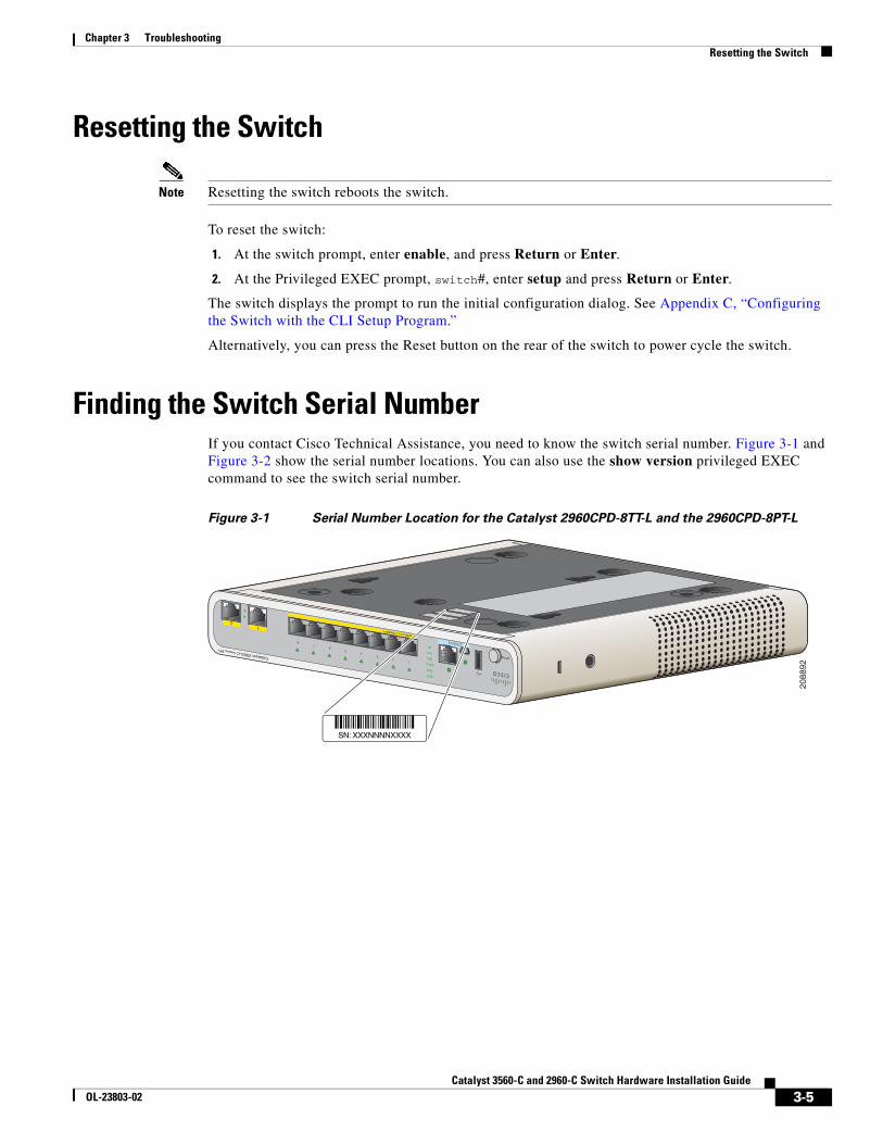
Chapter 3 TroubleshootingResetting the Switch
Resetting the Switch
Note Resetting the switch reboots the switch.
To reset the switch:
1. At the switch prompt, enter enable, and press Return or Enter.
2. At the Privileged EXEC prompt, switch#, enter setup and press Return or Enter.
The switch displays the prompt to run the initial configuration dialog. See Appendix C, “Configuring the Switch with the CLI Setup Program.”
Alternatively, you can press the Reset button on the rear of the switch to power cycle the switch.
Finding the Switch Serial NumberIf you contact Cisco Technical Assistance, you need to know the switch serial number. Figure 3-1 and Figure 3-2 show the serial number locations. You can also use the show version privileged EXEC command to see the switch serial number.
Figure 3-1 Serial Number Location for the Catalyst 2960CPD-8TT-L and the 2960CPD-8PT-L
MODE
PD
SPD
PoE
DPLX
STAT
SYST
Catalyst 2960-CSeries PD
12
34
56
78
21
CONSOLE
POWER OVER ETHERNET
SN: XXXNNNNXXXX
2088
92
3-5Catalyst 3560-C and 2960-C Switch Hardware Installation Guide
OL-23803-02
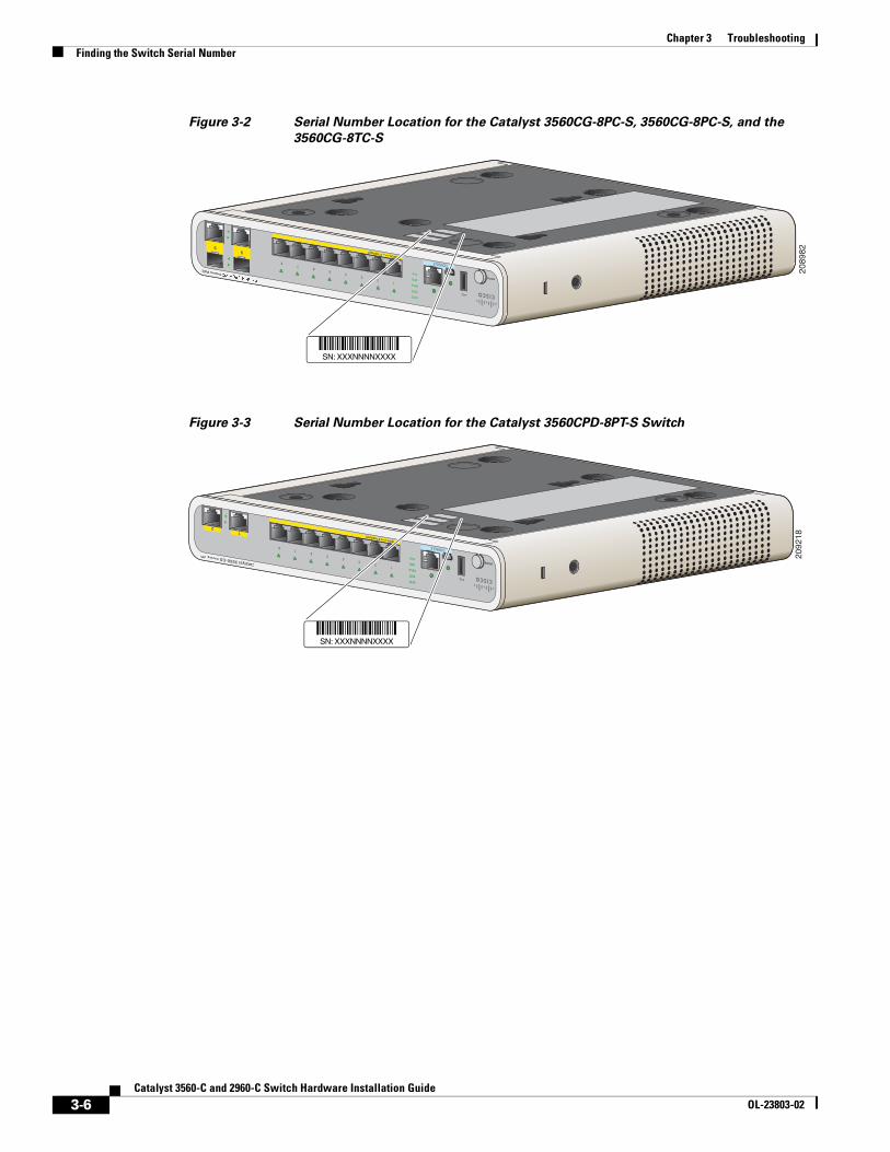
Chapter 3 TroubleshootingFinding the Switch Serial Number
Figure 3-2 Serial Number Location for the Catalyst 3560CG-8PC-S, 3560CG-8PC-S, and the
3560CG-8TC-S
Figure 3-3 Serial Number Location for the Catalyst 3560CPD-8PT-S Switch
MODESPD
PoE
DPLX
STAT
SYST
12
34
56
78
21
CONSOLE
POWER OVER ETHERNET99
Series PoE
SN: XXXNNNNXXXX
2089
82
MODESPD
PoE
DPLX
STAT
SYST
Catalyst 3560-CG SeriesPD
12
34
56
78
21
CONSOLE
POWER OVER ETHERNET
SN: XXXNNNNXXXX
2092
18
3-6Catalyst 3560-C and 2960-C Switch Hardware Installation Guide
OL-23803-02
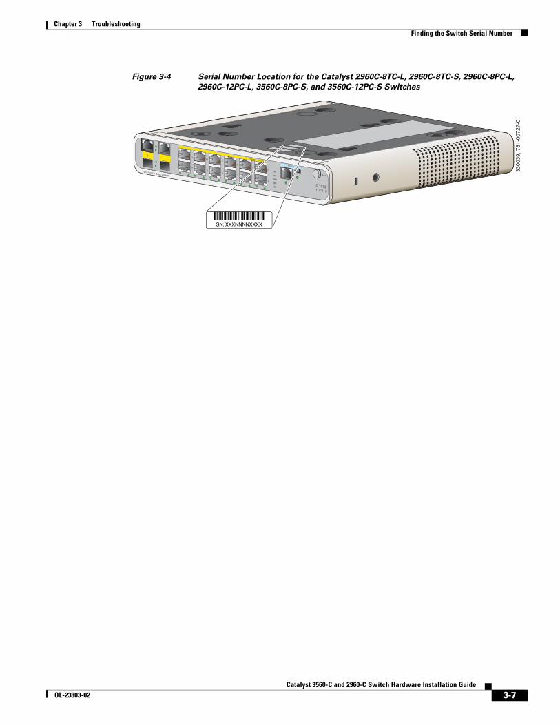
Chapter 3 TroubleshootingFinding the Switch Serial Number
Figure 3-4 Serial Number Location for the Catalyst 2960C-8TC-L, 2960C-8TC-S, 2960C-8PC-L,
2960C-12PC-L, 3560C-8PC-S, and 3560C-12PC-S Switches
ESPD
PoE
DPLX
STAT
SYST
12
34
56
78
21
CONSOLE
121
1
MODECatalyst 3960-C SeriesPoE
SPD
PoE
DPLX
STAT
SYST
1
2
3
4
57
911 CONSOLE
POWER OVERETHERNET
68
1012
SN: XXXNNNNXXXX
3300
39, 7
81-0
0727
-01
3-7Catalyst 3560-C and 2960-C Switch Hardware Installation Guide
OL-23803-02

Chapter 3 TroubleshootingFinding the Switch Serial Number
3-8Catalyst 3560-C and 2960-C Switch Hardware Installation Guide
OL-23803-02
Catalyst 3560-C andOL-23803-02
A
P P E N D I X A Technical SpecificationsTable A-1 Environmental and Physical Specifications for the Catalyst 3560-C and 2960-C
Switches
Environmental Ranges
Operating temperature
Catalyst 2960CPD-8TT-L Catalyst 2960CPD-8PT-LCatalyst 2960C-8TC-LCatalyst 2960C-8TC-SCatalyst 2960C-8PC-LCatalyst 2960C-12PC-LCatalyst 3560C-8PC-SCatalyst 3560C-12PC-S
23 to 113°F (–5 to 45°C) up to 5000 ft (1524 m)
Catalyst 2960CG-8TC-LCatalyst 3560CG-8PC-S Catalyst 3560CG-8TC-S Catalyst 3560CPD-8PT-S
23 to 104°F (–5 to 40°C) up to 5000 ft (1524 m)
Storage temperature –22 to 158°F (–30 to 70°C) up to 15,000 ft (4573 m)
Relative humidity 5 to 95% (noncondensing)
Operating altitude Up to 10,000 ft (3049 m)
Storage altitude Up to 15,000 ft (4570 m)
A-1 2960-C Switch Hardware Installation Guide
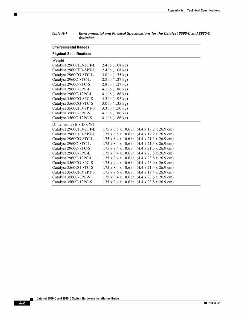
Appendix A Technical Specifications
Physical Specifications
WeightCatalyst 2960CPD-8TT-LCatalyst 2960CPD-8PT-LCatalyst 2960CG-8TC-L Catalyst 2960C-8TC-LCatalyst 2960C-8TC-SCatalyst 2960C-8PC-LCatalyst 2960C-12PC-LCatalyst 3560CG-8PC-SCatalyst 3560CG-8TC-SCatalyst 3560CPD-8PT-SCatalyst 3560C-8PC-SCatalyst 3560C-12PC-S
2.4 lb (1.08 kg)2.4 lb (1.08 kg)3.0 lb (1.35 kg)2.8 lb (1.27 kg)2.8 lb (1.27 kg)4.1 lb (1.86 kg)4.1 lb (1.86 kg)4.3 lb (1.92 kg)3.0 lb (1.35 kg)3.3 lb (1.50 kg)4.1 lb (1.86 kg)4.1 lb (1.86 kg)
Dimensions (H x D x W)Catalyst 2960CPD-8TT-LCatalyst 2960CPD-8PT-LCatalyst 2960CG-8TC-LCatalyst 2960C-8TC-LCatalyst 2960C-8TC-SCatalyst 2960C-8PC-LCatalyst 2960C-12PC-LCatalyst 3560CG-8PC-S Catalyst 3560CG-8TC-SCatalyst 3560CPD-8PT-SCatalyst 3560C-8PC-SCatalyst 3560C-12PC-S
1.75 x 6.8 x 10.6 in. (4.4 x 17.2 x 26.9 cm)1.75 x 6.8 x 10.6 in. (4.4 x 17.2 x 26.9 cm)1.75 x 8.4 x 10.6 in. (4.4 x 21.3 x 26.9 cm)1.75 x 8.4 x 10.6 in. (4.4 x 21.3 x 26.9 cm)1.75 x 8.4 x 10.6 in. (4.4 x 21.3 x 26.9 cm)1.75 x 9.4 x 10.6 in. (4.4 x 23.8 x 26.9 cm)1.75 x 9.4 x 10.6 in. (4.4 x 23.8 x 26.9 cm)1.75 x 9.4 x 10.6 in. (4.4 x 23.9 x 26.9 cm)1.75 x 8.4 x 10.6 in. (4.4 x 21.3 x 26.9 cm)1.75 x 7.6 x 10.6 in. (4.4 x 19.4 x 26.9 cm)1.75 x 9.4 x 10.6 in. (4.4 x 23.8 x 26.9 cm)1.75 x 9.4 x 10.6 in. (4.4 x 23.8 x 26.9 cm)
Table A-1 Environmental and Physical Specifications for the Catalyst 3560-C and 2960-C
Switches
Environmental Ranges
A-2Catalyst 3560-C and 2960-C Switch Hardware Installation Guide
OL-23803-02
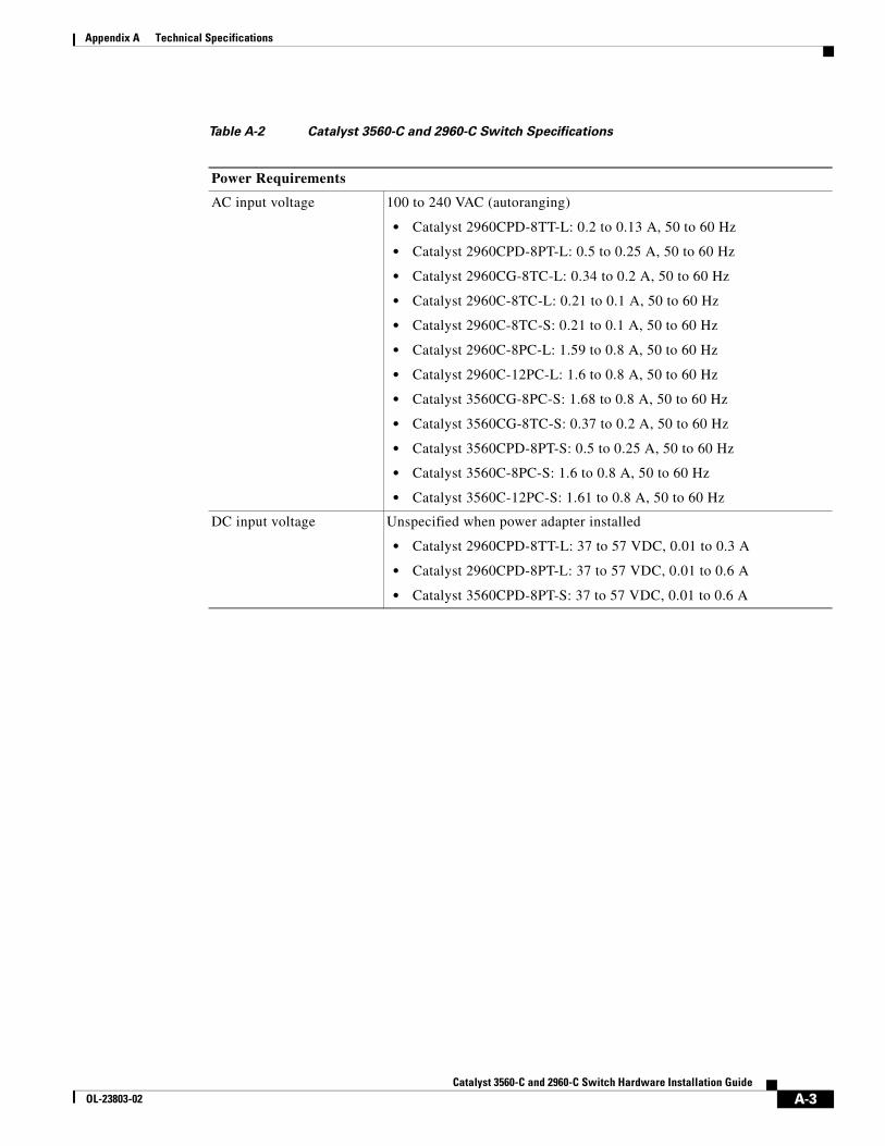
Appendix A Technical Specifications
Table A-2 Catalyst 3560-C and 2960-C Switch Specifications
Power Requirements
AC input voltage 100 to 240 VAC (autoranging)
• Catalyst 2960CPD-8TT-L: 0.2 to 0.13 A, 50 to 60 Hz
• Catalyst 2960CPD-8PT-L: 0.5 to 0.25 A, 50 to 60 Hz
• Catalyst 2960CG-8TC-L: 0.34 to 0.2 A, 50 to 60 Hz
• Catalyst 2960C-8TC-L: 0.21 to 0.1 A, 50 to 60 Hz
• Catalyst 2960C-8TC-S: 0.21 to 0.1 A, 50 to 60 Hz
• Catalyst 2960C-8PC-L: 1.59 to 0.8 A, 50 to 60 Hz
• Catalyst 2960C-12PC-L: 1.6 to 0.8 A, 50 to 60 Hz
• Catalyst 3560CG-8PC-S: 1.68 to 0.8 A, 50 to 60 Hz
• Catalyst 3560CG-8TC-S: 0.37 to 0.2 A, 50 to 60 Hz
• Catalyst 3560CPD-8PT-S: 0.5 to 0.25 A, 50 to 60 Hz
• Catalyst 3560C-8PC-S: 1.6 to 0.8 A, 50 to 60 Hz
• Catalyst 3560C-12PC-S: 1.61 to 0.8 A, 50 to 60 Hz
DC input voltage Unspecified when power adapter installed
• Catalyst 2960CPD-8TT-L: 37 to 57 VDC, 0.01 to 0.3 A
• Catalyst 2960CPD-8PT-L: 37 to 57 VDC, 0.01 to 0.6 A
• Catalyst 3560CPD-8PT-S: 37 to 57 VDC, 0.01 to 0.6 A
A-3Catalyst 3560-C and 2960-C Switch Hardware Installation Guide
OL-23803-02
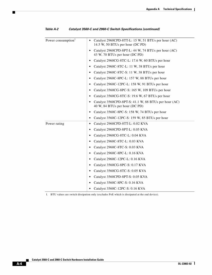
Appendix A Technical Specifications
Power consumption1 • Catalyst 2960CPD-8TT-L: 15 W, 51 BTUs per hour (AC) 14.5 W, 50 BTUs per hour (DC PD)
• Catalyst 2960CPD-8PT-L: 44 W, 74 BTUs per hour (AC) 43 W, 70 BTUs per hour (DC PD)
• Catalyst 2960CG-8TC-L: 17.6 W, 60 BTUs per hour
• Catalyst 2960C-8TC-L: 11 W, 38 BTUs per hour
• Catalyst 2960C-8TC-S: 11 W, 38 BTUs per hour
• Catalyst 2960C-8PC-L: 157 W, 88 BTUs per hour
• Catalyst 2960C-12PC-L: 158 W, 91 BTUs per hour
• Catalyst 3560CG-8PC-S: 165 W, 109 BTUs per hour
• Catalyst 3560CG-8TC-S: 19.6 W, 67 BTUs per hour
• Catalyst 3560CPD-8PT-S: 41.1 W, 88 BTUs per hour (AC) 40 W, 84 BTUs per hour (DC PD)
• Catalyst 3560C-8PC-S: 158 W, 74 BTUs per hour
• Catalyst 3560C-12PC-S: 159 W, 85 BTUs per hour
Power rating • Catalyst 2960CPD-8TT-L: 0.02 KVA
• Catalyst 2960CPD-8PT-L: 0.05 KVA
• Catalyst 2960CG-8TC-L: 0.04 KVA
• Catalyst 2960C-8TC-L: 0.03 KVA
• Catalyst 2960C-8TC-S: 0.03 KVA
• Catalyst 2960C-8PC-L: 0.16 KVA
• Catalyst 2960C-12PC-L: 0.16 KVA
• Catalyst 3560CG-8PC-S: 0.17 KVA
• Catalyst 3560CG-8TC-S: 0.05 KVA
• Catalyst 3560CPD-8PT-S: 0.05 KVA
• Catalyst 3560C-8PC-S: 0.16 KVA
• Catalyst 3560C-12PC-S: 0.16 KVA
1. BTU values are switch dissipation only (excludes PoE which is dissipated at the end device).
Table A-2 Catalyst 3560-C and 2960-C Switch Specifications (continued)
A-4Catalyst 3560-C and 2960-C Switch Hardware Installation Guide
OL-23803-02
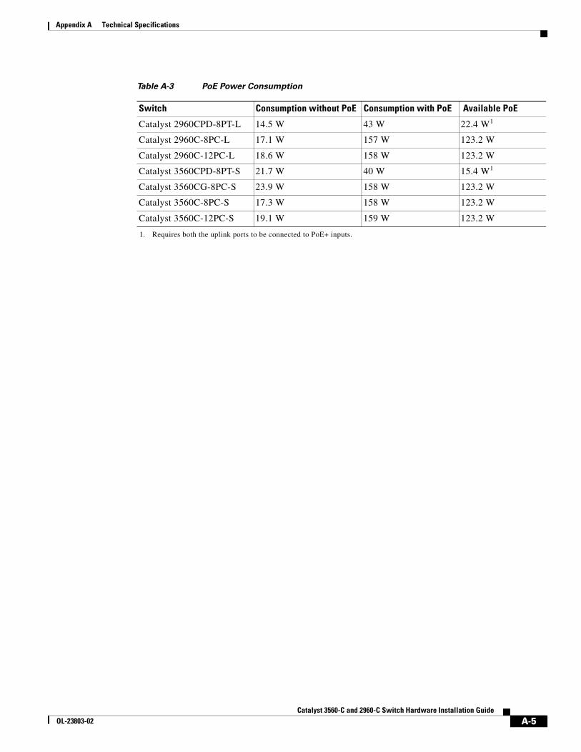
Appendix A Technical Specifications
Table A-3 PoE Power Consumption
Switch Consumption without PoE Consumption with PoE Available PoE
Catalyst 2960CPD-8PT-L 14.5 W 43 W 22.4 W1
1. Requires both the uplink ports to be connected to PoE+ inputs.
Catalyst 2960C-8PC-L 17.1 W 157 W 123.2 W
Catalyst 2960C-12PC-L 18.6 W 158 W 123.2 W
Catalyst 3560CPD-8PT-S 21.7 W 40 W 15.4 W1
Catalyst 3560CG-8PC-S 23.9 W 158 W 123.2 W
Catalyst 3560C-8PC-S 17.3 W 158 W 123.2 W
Catalyst 3560C-12PC-S 19.1 W 159 W 123.2 W
A-5Catalyst 3560-C and 2960-C Switch Hardware Installation Guide
OL-23803-02

Appendix A Technical Specifications
A-6Catalyst 3560-C and 2960-C Switch Hardware Installation Guide
OL-23803-02
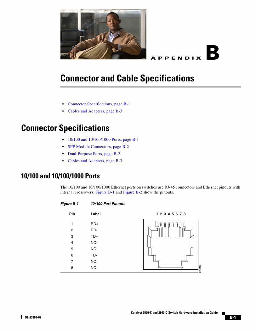
Catalyst 3560-C andOL-23803-02
A
P P E N D I X B Connector and Cable Specifications• Connector Specifications, page B-1
• Cables and Adapters, page B-3
Connector Specifications• 10/100 and 10/100/1000 Ports, page B-1
• SFP Module Connectors, page B-2
• Dual-Purpose Ports, page B-2
• Cables and Adapters, page B-3
10/100 and 10/100/1000 PortsThe 10/100 and 10/100/1000 Ethernet ports on switches use RJ-45 connectors and Ethernet pinouts with internal crossovers. Figure B-1 and Figure B-2 show the pinouts.
Figure B-1 10/100 Port Pinouts
H53
18
2 31 4 5 6 7 8Pin Label
1
2
3
4
5
6
7
8
RD+
RD-
TD+
NC
NC
TD-
NC
NC
B-1 2960-C Switch Hardware Installation Guide
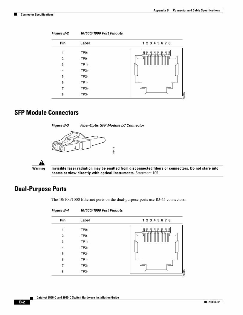
Appendix B Connector and Cable SpecificationsConnector Specifications
Figure B-2 10/100/1000 Port Pinouts
SFP Module Connectors
Figure B-3 Fiber-Optic SFP Module LC Connector
Warning Invisible laser radiation may be emitted from disconnected fibers or connectors. Do not stare into beams or view directly with optical instruments. Statement 1051
Dual-Purpose PortsThe 10/100/1000 Ethernet ports on the dual-purpose ports use RJ-45 connectors.
Figure B-4 10/100/1000 Port Pinouts
6091
5
2 31 4 5 6 7 8Pin Label
1
2
3
4
5
6
7
8
TP0+
TP0-
TP1+
TP2+
TP2-
TP1-
TP3+
TP3-
5847
6
6091
5
2 31 4 5 6 7 8Pin Label
1
2
3
4
5
6
7
8
TP0+
TP0-
TP1+
TP2+
TP2-
TP1-
TP3+
TP3-
B-2Catalyst 3560-C and 2960-C Switch Hardware Installation Guide
OL-23803-02
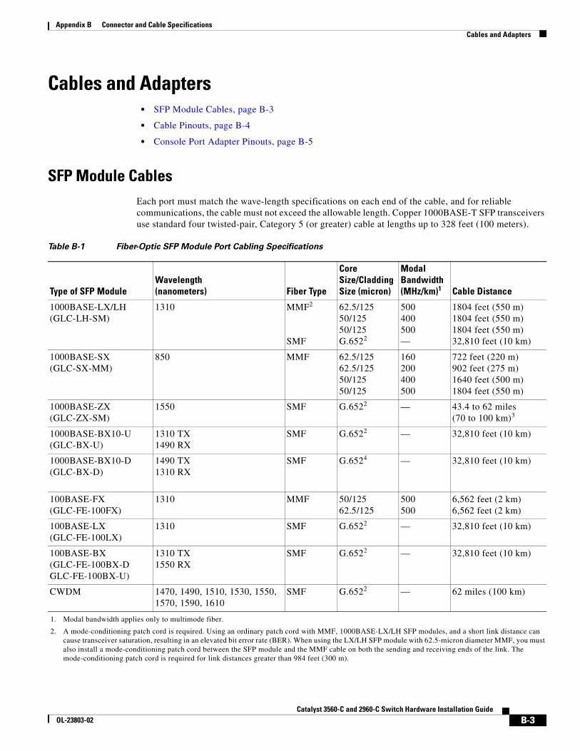
Appendix B Connector and Cable SpecificationsCables and Adapters
Cables and Adapters • SFP Module Cables, page B-3
• Cable Pinouts, page B-4
• Console Port Adapter Pinouts, page B-5
SFP Module Cables Each port must match the wave-length specifications on each end of the cable, and for reliable communications, the cable must not exceed the allowable length. Copper 1000BASE-T SFP transceivers use standard four twisted-pair, Category 5 (or greater) cable at lengths up to 328 feet (100 meters).
Table B-1 Fiber-Optic SFP Module Port Cabling Specifications
Type of SFP ModuleWavelength (nanometers) Fiber Type
Core Size/Cladding Size (micron)
Modal Bandwidth (MHz/km)1
1. Modal bandwidth applies only to multimode fiber.
Cable Distance
1000BASE-LX/LH(GLC-LH-SM)
1310 MMF2
SMF
2. A mode-conditioning patch cord is required. Using an ordinary patch cord with MMF, 1000BASE-LX/LH SFP modules, and a short link distance can cause transceiver saturation, resulting in an elevated bit error rate (BER). When using the LX/LH SFP module with 62.5-micron diameter MMF, you must also install a mode-conditioning patch cord between the SFP module and the MMF cable on both the sending and receiving ends of the link. The mode-conditioning patch cord is required for link distances greater than 984 feet (300 m).
62.5/12550/12550/125G.6522
500400500—
1804 feet (550 m)1804 feet (550 m)1804 feet (550 m)32,810 feet (10 km)
1000BASE-SX(GLC-SX-MM)
850 MMF 62.5/12562.5/12550/12550/125
160200400500
722 feet (220 m)902 feet (275 m)1640 feet (500 m)1804 feet (550 m)
1000BASE-ZX(GLC-ZX-SM)
1550 SMF G.6522 — 43.4 to 62 miles (70 to 100 km)3
1000BASE-BX10-U(GLC-BX-U)
1310 TX1490 RX
SMF G.6522 — 32,810 feet (10 km)
1000BASE-BX10-D(GLC-BX-D)
1490 TX1310 RX
SMF G.6524 — 32,810 feet (10 km)
100BASE-FX (GLC-FE-100FX)
1310 MMF 50/12562.5/125
500500
6,562 feet (2 km) 6,562 feet (2 km)
100BASE-LX (GLC-FE-100LX)
1310 SMF G.6522 — 32,810 feet (10 km)
100BASE-BX (GLC-FE-100BX-DGLC-FE-100BX-U)
1310 TX1550 RX
SMF G.6522 — 32,810 feet (10 km)
CWDM 1470, 1490, 1510, 1530, 1550, 1570, 1590, 1610
SMF G.6522 — 62 miles (100 km)
B-3Catalyst 3560-C and 2960-C Switch Hardware Installation Guide
OL-23803-02
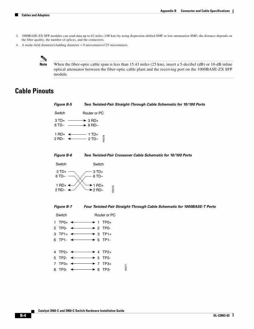
Appendix B Connector and Cable SpecificationsCables and Adapters
Note When the fiber-optic cable span is less than 15.43 miles (25 km), insert a 5-decibel (dB) or 10-dB inline optical attenuator between the fiber-optic cable plant and the receiving port on the 1000BASE-ZX SFP module.
Cable Pinouts
Figure B-5 Two Twisted-Pair Straight-Through Cable Schematic for 10/100 Ports
Figure B-6 Two Twisted-Pair Crossover Cable Schematic for 10/100 Ports
Figure B-7 Four Twisted-Pair Straight-Through Cable Schematic for 1000BASE-T Ports
3. 1000BASE-ZX SFP modules can send data up to 62 miles (100 km) by using dispersion-shifted SMF or low-attenuation SMF; the distance depends on the fiber quality, the number of splices, and the connectors.
4. A mode-field diameter/cladding diameter = 9 micrometers/125 micrometers.
Switch
3 TD+6 TD–
1 RD+2 RD–
Router or PC
3 RD+6 RD–
1 TD+2 TD–
H55
78
Switch
3 TD+6 TD–
1 RD+2 RD–
Switch
3 TD+6 TD–
1 RD+2 RD–
H55
79
1 TP0+
2 TP0-
3 TP1+
6 TP1-
1 TP0+
2 TP0-
3 TP1+
6 TP1-
Switch Router or PC
4 TP2+
5 TP2-
7 TP3+
8 TP3-
4 TP2+
5 TP2-
7 TP3+
8 TP3- 6527
1
B-4Catalyst 3560-C and 2960-C Switch Hardware Installation Guide
OL-23803-02
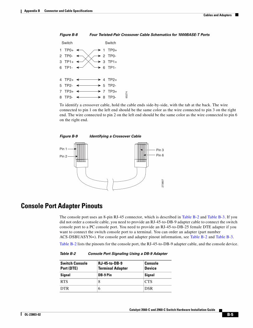
Appendix B Connector and Cable SpecificationsCables and Adapters
Figure B-8 Four Twisted-Pair Crossover Cable Schematics for 1000BASE-T Ports
To identify a crossover cable, hold the cable ends side-by-side, with the tab at the back. The wire connected to pin 1 on the left end should be the same color as the wire connected to pin 3 on the right end. The wire connected to pin 2 on the left end should be the same color as the wire connected to pin 6 on the right end.
Figure B-9 Identifying a Crossover Cable
Console Port Adapter PinoutsThe console port uses an 8-pin RJ-45 connector, which is described in Table B-2 and Table B-3. If you did not order a console cable, you need to provide an RJ-45-to-DB-9 adapter cable to connect the switch console port to a PC console port. You need to provide an RJ-45-to-DB-25 female DTE adapter if you want to connect the switch console port to a terminal. You can order an adapter (part number ACS-DSBUASYN=). For console port and adapter pinout information, see Table B-2 and Table B-3.
Table B-2 lists the pinouts for the console port, the RJ-45-to-DB-9 adapter cable, and the console device.
1 TP0+
2 TP0-
3 TP1+
6 TP1-
1 TP0+
Switch Switch
2 TP0-
3 TP1+
6 TP1-
4 TP2+
5 TP2-
7 TP3+
8 TP3-
4 TP2+
5 TP2-
7 TP3+
8 TP3- 6527
4
Pin 1
Pin 2
2738
07
Pin 6
Pin 3
Table B-2 Console Port Signaling Using a DB-9 Adapter
Switch ConsolePort (DTE)
RJ-45-to-DB-9Terminal Adapter
ConsoleDevice
Signal DB-9 Pin Signal
RTS 8 CTS
DTR 6 DSR
B-5Catalyst 3560-C and 2960-C Switch Hardware Installation Guide
OL-23803-02
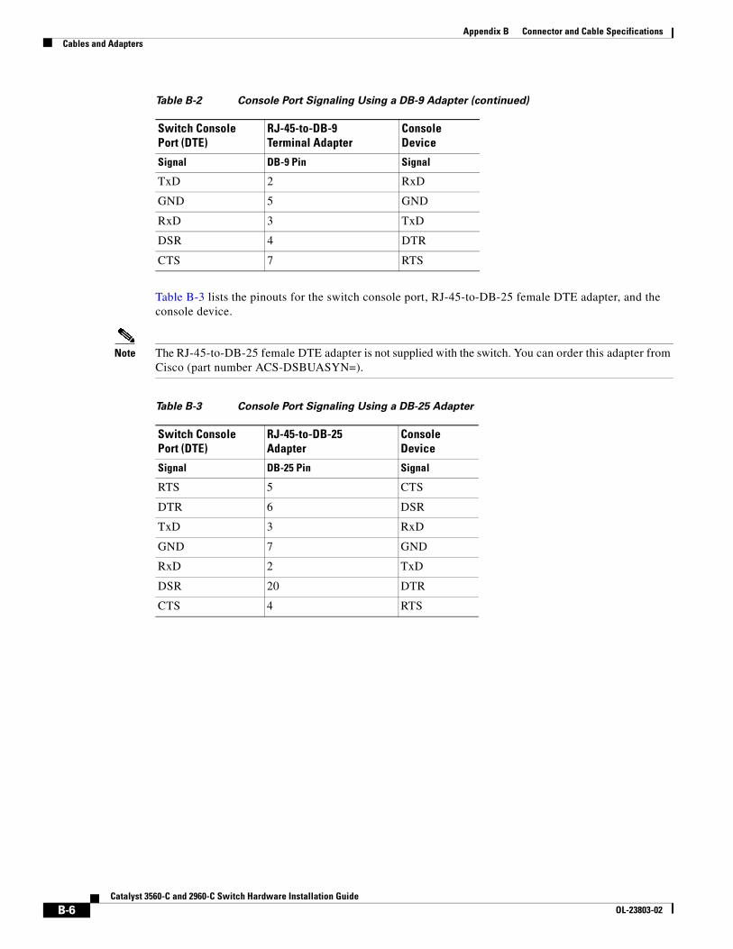
Appendix B Connector and Cable SpecificationsCables and Adapters
Table B-3 lists the pinouts for the switch console port, RJ-45-to-DB-25 female DTE adapter, and the console device.
Note The RJ-45-to-DB-25 female DTE adapter is not supplied with the switch. You can order this adapter from Cisco (part number ACS-DSBUASYN=).
TxD 2 RxD
GND 5 GND
RxD 3 TxD
DSR 4 DTR
CTS 7 RTS
Table B-2 Console Port Signaling Using a DB-9 Adapter (continued)
Switch ConsolePort (DTE)
RJ-45-to-DB-9Terminal Adapter
ConsoleDevice
Signal DB-9 Pin Signal
Table B-3 Console Port Signaling Using a DB-25 Adapter
Switch ConsolePort (DTE)
RJ-45-to-DB-25Adapter
ConsoleDevice
Signal DB-25 Pin Signal
RTS 5 CTS
DTR 6 DSR
TxD 3 RxD
GND 7 GND
RxD 2 TxD
DSR 20 DTR
CTS 4 RTS
B-6Catalyst 3560-C and 2960-C Switch Hardware Installation Guide
OL-23803-02
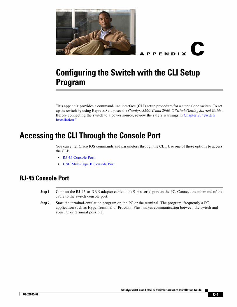
Catalyst 3560-C andOL-23803-02
A
P P E N D I X C Configuring the Switch with the CLI Setup ProgramThis appendix provides a command-line interface (CLI) setup procedure for a standalone switch. To set up the switch by using Express Setup, see the Catalyst 3560-C and 2960-C Switch Getting Started Guide. Before connecting the switch to a power source, review the safety warnings in Chapter 2, “Switch Installation.”
Accessing the CLI Through the Console PortYou can enter Cisco IOS commands and parameters through the CLI. Use one of these options to access the CLI:
• RJ-45 Console Port
• USB Mini-Type B Console Port
RJ-45 Console Port
Step 1 Connect the RJ-45-to-DB-9 adapter cable to the 9-pin serial port on the PC. Connect the other end of the cable to the switch console port.
Step 2 Start the terminal-emulation program on the PC or the terminal. The program, frequently a PC application such as HyperTerminal or ProcommPlus, makes communication between the switch and your PC or terminal possible.
C-1 2960-C Switch Hardware Installation Guide
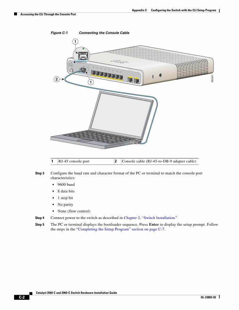
Appendix C Configuring the Switch with the CLI Setup ProgramAccessing the CLI Through the Console Port
Figure C-1 Connecting the Console Cable
Step 3 Configure the baud rate and character format of the PC or terminal to match the console port characteristics:
• 9600 baud
• 8 data bits
• 1 stop bit
• No parity
• None (flow control)
Step 4 Connect power to the switch as described in Chapter 2, “Switch Installation.”
Step 5 The PC or terminal displays the bootloader sequence. Press Enter to display the setup prompt. Follow the steps in the “Completing the Setup Program” section on page C-7.
1 RJ-45 console port 2 Console cable (RJ-45-to-DB-9 adapter cable)
M O DE
CO NSO LE
12
Catalyst 2960-C Series PD
PO W ER OVER ETHERNET
12
34
56
78
PD
SPD
PoE
DPLX
STAT
SYST
2824
01
CONSOL E
2
1
1
C-2Catalyst 3560-C and 2960-C Switch Hardware Installation Guide
OL-23803-02
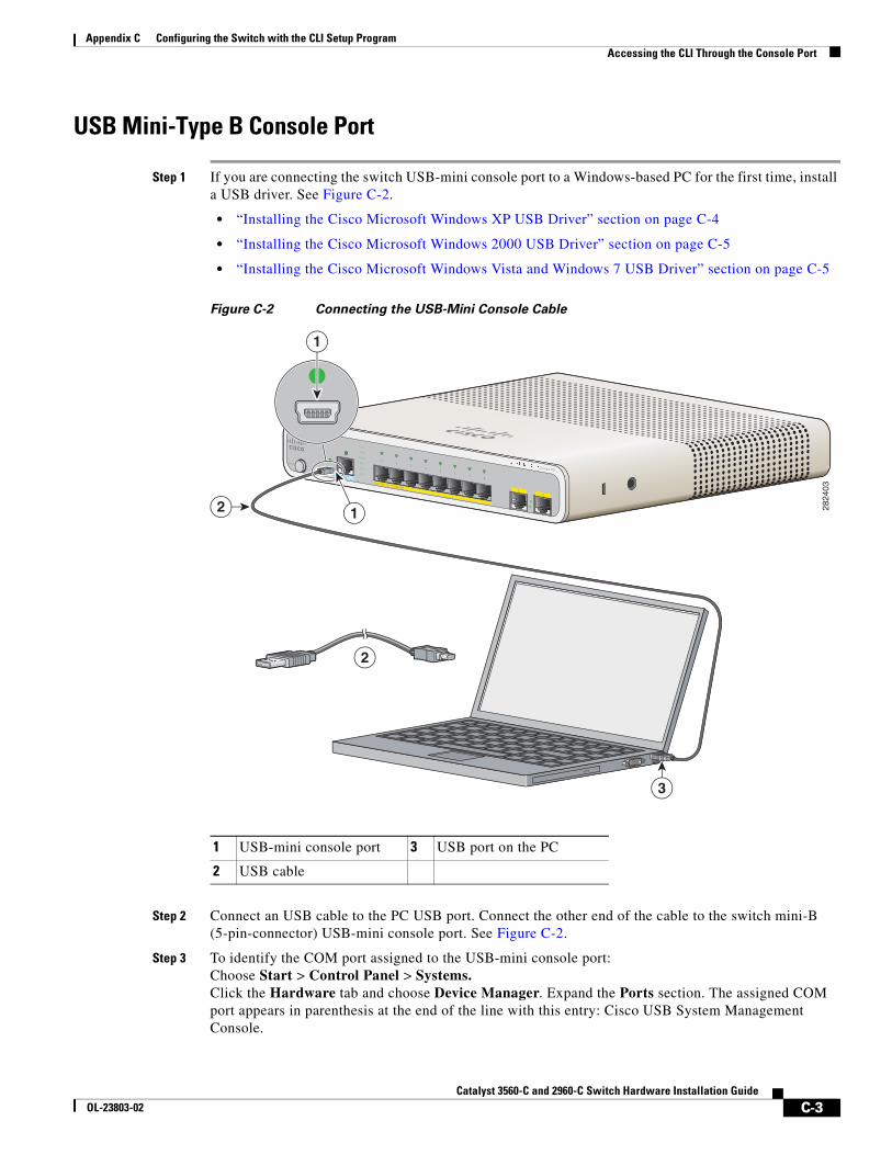
Appendix C Configuring the Switch with the CLI Setup ProgramAccessing the CLI Through the Console Port
USB Mini-Type B Console Port
Step 1 If you are connecting the switch USB-mini console port to a Windows-based PC for the first time, install a USB driver. See Figure C-2.
• “Installing the Cisco Microsoft Windows XP USB Driver” section on page C-4
• “Installing the Cisco Microsoft Windows 2000 USB Driver” section on page C-5
• “Installing the Cisco Microsoft Windows Vista and Windows 7 USB Driver” section on page C-5
Figure C-2 Connecting the USB-Mini Console Cable
Step 2 Connect an USB cable to the PC USB port. Connect the other end of the cable to the switch mini-B (5-pin-connector) USB-mini console port. See Figure C-2.
Step 3 To identify the COM port assigned to the USB-mini console port: Choose Start > Control Panel > Systems. Click the Hardware tab and choose Device Manager. Expand the Ports section. The assigned COM port appears in parenthesis at the end of the line with this entry: Cisco USB System Management Console.
1 USB-mini console port 3 USB port on the PC
2 USB cable
M O DE
CO NSO LE
12
Series PD
PO W ER OVER ETHERNET
12
34
56
78
PD
SPD
PoE
DPLX
STAT
SYST
2824
03
3
2
2
1
1
C-3Catalyst 3560-C and 2960-C Switch Hardware Installation Guide
OL-23803-02
Appendix C Configuring the Switch with the CLI Setup ProgramAccessing the CLI Through the Console Port
Step 4 Start the terminal-emulation program on the PC or the terminal. The program, frequently a PC application such as HyperTerminal or ProcommPlus, makes communication possible between the switch and your PC or terminal.
Step 5 Configure the COM port.
Step 6 Configure the baud rate and character format of the PC or terminal to match the console port characteristics:
• 9600 baud
• 8 data bits
• 1 stop bit
• No parity
• None (flow control)
Step 7 Connect power to the switch as described in Chapter 2, “Switch Installation.”
Step 8 The PC or terminal displays the bootloader sequence. Press Enter to display the setup prompt. Follow the steps in the “Completing the Setup Program” section on page C-7.
Installing the Cisco Microsoft Windows USB Device Drivers
Installing the Cisco Microsoft Windows XP USB Driver
Step 1 Obtain the file Cisco_usbconsole_driver.zip from Cisco.com, and unzip it.
Note You can download the driver file from the Cisco.com software download site.
Step 2 If using 32-bit Windows XP, double-click the setup.exe file in the Windows_32 folder. If using 64-bit Windows XP, double-click the setup(x64).exe file in the Windows_64 folder.
Step 3 The Cisco Virtual Com InstallShield Wizard begins.
Step 4 The Ready to Install the Program window appears. Click Install.
Step 5 The InstallShield Wizard Completed window appears. Click Finish.
Step 6 Connect the USB cable to the PC and to the switch console port. The USB-mini console port LED turns green, and the Found New Hardware Wizard appears. Follow the instructions to complete the driver installation.
C-4Catalyst 3560-C and 2960-C Switch Hardware Installation Guide
OL-23803-02
Appendix C Configuring the Switch with the CLI Setup ProgramAccessing the CLI Through the Console Port
Installing the Cisco Microsoft Windows 2000 USB Driver
Step 1 Obtain the file Cisco_usbconsole_driver.zip from Cisco.com, and unzip it.
Note You can download the driver file from the Cisco.com software download site.
Step 2 Double-click the setup.exe file.
Step 3 The Cisco Virtual Com InstallShield Wizard begins. Click Next.
Step 4 The Ready to Install the Program window appears. Click Install.
Step 5 The InstallShield Wizard Completed window appears. Click Finish.
Step 6 Connect the USB cable to the PC and to the switch console port. The USB-mini console port LED turns green, and the Found New Hardware Wizard appears. Follow the instructions to complete the driver installation.
Installing the Cisco Microsoft Windows Vista and Windows 7 USB Driver
Step 1 Obtain the file Cisco_usbconsole_driver.zip from Cisco.com, and unzip it.
Note You can download the driver file from the Cisco.com software download site.
Step 2 If using 32-bit Windows Vista or Windows 7, double-click the setup.exe file in the Windows_32 folder. If using 64-bit Windows Vista or Windows 7, double-click the setup(x64).exe file in the Windows_64 folder.
Step 3 The Cisco Virtual Com InstallShield Wizard begins. Click Next.
Step 4 The Ready to Install the Program window appears. Click Install.
Note If a User Account Control warning appears, click Allow - I trust this program.
Step 5 The InstallShield Wizard Completed window appears. Click Finish.
Step 6 Connect the USB cable to the PC and to the switch console port. The USB-mini console port LED turns green, and the Found New Hardware Wizard appears. Follow the instructions to complete the driver installation.
C-5Catalyst 3560-C and 2960-C Switch Hardware Installation Guide
OL-23803-02
Appendix C Configuring the Switch with the CLI Setup ProgramAccessing the CLI Through the Console Port
Uninstalling the Cisco Microsoft Windows USB Drivers
Uninstalling the Cisco Microsoft Windows XP and 2000 USB Driver
You can uninstall the driver by using the Windows Add or Remove Programs utility or by using the setup.exe file.
Using the Add or Remove Programs Utility
Note Disconnect the switch console terminal before uninstalling the driver.
Step 1 Choose Start > Control Panel > Add or Remove Programs.
Step 2 Scroll to Cisco Virtual Com, and click Remove.
Step 3 When the Program Maintenance window appears, select the Remove radio button. Click Next.
Using the Setup.exe Program
Note Disconnect the switch console terminal before uninstalling the driver.
Step 1 Run setup.exe for 32-bit Windows or setup(x64).exe for 64-bit Windows. Click Next.
Step 2 The InstallShield Wizard for Cisco Virtual Com appears. Click Next.
Step 3 When the Program Maintenance window appears, click the Select the radio button. Click Next.
Step 4 When the Remove the Program window appears, select Remove.
Step 5 When the InstallShield Wizard Completed window appears, click Finish.
Uninstalling the Cisco Microsoft Windows Vista and Windows 7 USB Driver
Note Disconnect the switch console terminal before uninstalling the driver.
Step 1 Run setup.exe for 32-bit Windows or setup(x64).exe for 64-bit Windows. Click Next.
Step 2 The InstallShield Wizard for Cisco Virtual Com appears. Click Next.
Step 3 When the Program Maintenance window appears, select the Remove radio button. Click Next.
C-6Catalyst 3560-C and 2960-C Switch Hardware Installation Guide
OL-23803-02
Appendix C Configuring the Switch with the CLI Setup ProgramEntering the Initial Configuration Information
Step 4 When the Remove the Program window appears, click Remove.
Note If a User Account Control warning appears, click Allow - I trust this program to proceed.
Step 5 When the InstallShield Wizard Completed window appears, click Finish.
Entering the Initial Configuration Information To set up the switch, you need to complete the setup program, which runs automatically after the switch powers on. You must assign an IP address and other configuration information necessary for the switch to communicate with the local routers and the Internet.
IP SettingsYou need this information:
• Switch IP address
• Subnet mask (IP netmask)
• Default gateway (router)
• Enable secret password
• Enable password
• Telnet password
Completing the Setup ProgramFollow these steps to complete the setup program and to create an initial configuration for the switch:
Step 1 Enter Yes at these two prompts.
Would you like to enter the initial configuration dialog? [yes/no]: yes
At any point you may enter a question mark '?' for help.Use ctrl-c to abort configuration dialog at any prompt.Default settings are in square brackets '[]'.
Basic management setup configures only enough connectivityfor management of the system, extended setup will ask youto configure each interface on the system.
Would you like to enter basic management setup? [yes/no]: yes
Step 2 Enter a host name for the switch, and press Return.
On a command switch, the host name is limited to 28 characters and on a member switch to 31 characters. Do not use -n, where n is a number, as the last character in a host name for any switch.
Enter host name [Switch]: host_name
C-7Catalyst 3560-C and 2960-C Switch Hardware Installation Guide
OL-23803-02
Appendix C Configuring the Switch with the CLI Setup ProgramEntering the Initial Configuration Information
Step 3 Enter an enable secret password, and press Return.
The password can be from 1 to 25 alphanumeric characters, can start with a number, is case sensitive, allows spaces, but ignores leading spaces. The secret password is encrypted, and the enable password is in plain text.
Enter enable secret: secret_password
Step 4 Enter an enable password, and press Return.
Enter enable password: enable_password
Step 5 Enter a virtual terminal (Telnet) password, and press Return.
The password can be from 1 to 25 alphanumeric characters, is case sensitive, allows spaces, but ignores leading spaces.
Enter virtual terminal password: terminal-password
Step 6 (Optional) Configure Simple Network Management Protocol (SNMP) by responding to the prompts. You can also configure SNMP later through the CLI. To configure SNMP later, enter no.
Configure SNMP Network Management? [no]: no
Step 7 Enter the interface name (physical interface or VLAN name) of the interface that connects to the management network, and press Return. For this release, always use vlan1 as that interface.
Enter interface name used to connect to themanagement network from the above interface summary: vlan1
Step 8 Configure the interface by entering the switch IP address and subnet mask and pressing Return. The IP address and subnet masks shown below are examples.
Configuring interface vlan1:Configure IP on this interface? [yes]: yes IP address for this interface: 10.4.120.106Subnet mask for this interface [255.0.0.0]: 255.0.0.0
Step 9 Enter Y to configure the switch as the cluster command switch. Enter N to configure it as a member switch or as a standalone switch.
If you enter N, you can configure the switch as a command switch later through the CLI. To configure it later, enter no.
Would you like to enable as a cluster command switch? [yes/no]: no
You have completed the initial configuration of the switch, and the switch displays its configuration. This is an example of the configuration output:
The following configuration command script was created:hostname switch1enable secret 5 $1$Ulq8$DlA/OiaEbl90WcBPd9cOn1enable password enable_passwordline vty 0 15password terminal-passwordno snmp-server!no ip routing
!interface Vlan1no shutdownip address 10.4.120.106 255.0.0.0!interface FastEthernet1/0/1
C-8Catalyst 3560-C and 2960-C Switch Hardware Installation Guide
OL-23803-02
Appendix C Configuring the Switch with the CLI Setup ProgramEntering the Initial Configuration Information
!interface FastEthernet1/0/2
interface FastEthernet1/0/3!...<output abbreviated>end
Step 10 These choices appear:
[0] Go to the IOS command prompt without saving this config.
[1] Return back to the setup without saving this config.
[2] Save this configuration to nvram and exit.
If you want to save the configuration and use it the next time the switch reboots, select option 2 to save it in NVRAM.
Enter your selection [2]:2
Make your selection, and press Return.
After you complete the setup program, the switch can run the default configuration that you created. To change this configuration or to perform other management tasks, enter commands at the Switch> prompt.
C-9Catalyst 3560-C and 2960-C Switch Hardware Installation Guide
OL-23803-02

Appendix C Configuring the Switch with the CLI Setup ProgramEntering the Initial Configuration Information
C-10Catalyst 3560-C and 2960-C Switch Hardware Installation Guide
OL-23803-02