Embed Size (px)
Citation preview

Cisco EtherSwitch Service Modules Feature Guide
Note This document describes the Cisco EtherSwitch service module only. For information about the Cisco Ethernet switch network module, see “Connecting Ethernet Switch Network Modules to a Network” at the following URL: http://www.cisco.com/en/US/products/hw/modules/ps2797/products_module_installation_guide_chapter09186a00800b168c.html
The Cisco EtherSwitch service modules (NME-16ES-1G, NME-16ES-1G-P, NME-X-23ES-1G, NME-X-23ES-1G-P, NME-XD-48ES-2S-P, and NME-XD-24ES-1S-P) provide Cisco modular access routers the ability to stack Cisco EtherSwitch service modules as Layer 2 switches using Cisco StackWise technology. The Cisco EtherSwitch service modules are supported by either the IP base image (formerly known as standard multilayer image [SMI]) or the IP services image (formerly known as the enhanced multilayer image [EMI]). The IP base image provides Layer 2+ features, including access control lists (ACLs), quality of service (QoS), static routing, and the Routing Information Protocol (RIP). The IP services image provides a richer set of enterprise-class features, including Layer 2+ features and full Layer 3 routing (IP unicast routing, IP multicast routing, and fallback bridging). To distinguish it from the Layer 2+ static routing and RIP, the IP services image includes protocols such as the Enhanced Interior Gateway Routing Protocol (EIGRP) and the Open Shortest Path First (OSPF) Protocol.
Feature History for the Cisco EtherSwitch Service Modules (NME-16ES-1G-P, NME-X-23ES-1G-P, NME-XD-24ES-1S-P, NME-XD-48ES-2S-P)
Feature History for the Cisco EtherSwitch Service Modules (NME-16ES-1G, NME-X-23ES-1G)
Release Modification
12.2(25)EZ (switch software) This feature was introduced.
12.3(14)T (router software) This feature was introduced.
Release Modification
12.2(25)SEC (switch software) This feature was introduced.
12.3(14)T3 (router software) This feature was introduced.
Corporate Headquarters:
Copyright © 2005 Cisco Systems, Inc. All rights reserved.
Cisco Systems, Inc., 170 West Tasman Drive, San Jose, CA 95134-1706 USA

Cisco EtherSwitch Service Modules Feature GuideContents
Finding Support Information for Platforms and Cisco IOS Software Images
Use Cisco Feature Navigator to find information about platform support and Cisco IOS software image support. Access Cisco Feature Navigator at http://www.cisco.com/go/fn. You must have an account on Cisco.com. If you do not have an account or have forgotten your username or password, click Cancel at the login dialog box and follow the instructions that appear.
Contents• Prerequisites for the Cisco EtherSwitch Service Modules, page 2
• Information About the Cisco EtherSwitch Service Modules, page 2
• How to Configure the Cisco EtherSwitch Service Module, page 33
• How to Configure the Cisco EtherSwitch Service Module in a Switch Stack, page 50
• How to Configure a Switch Cluster, page 57
• Upgrading the Cisco EtherSwitch Service Module Software, page 63
• Troubleshooting the Cisco EtherSwitch Service Module Software, page 66
• Switch Stack Configuration Scenarios, page 78
• Network Configuration Examples, page 81
• Additional References, page 87
Prerequisites for the Cisco EtherSwitch Service ModulesThe Cisco IOS version on the Cisco EtherSwitch service modules must be compatible with the Cisco IOS software release and feature set on the router. See the “Feature History for the Cisco EtherSwitch Service Modules (NME-16ES-1G-P, NME-X-23ES-1G-P, NME-XD-24ES-1S-P, NME-XD-48ES-2S-P)” section on page 1 and the “Feature History for the Cisco EtherSwitch Service Modules (NME-16ES-1G, NME-X-23ES-1G)” section on page 1.
• To view the router, Cisco IOS software release and feature set, enter the show version command in privileged EXEC mode.
• To view the Cisco EtherSwitch service module IOS version, enter the dir flash: command in privileged EXEC mode.
Information About the Cisco EtherSwitch Service ModulesThis section describes the features and some important concepts about the Cisco EtherSwitch service modules:
• Hardware Overview, page 3
• Software Features and Benefits, page 4
• Cisco StackWise Concepts, page 12
• Clustering Concepts, page 20
2Cisco IOS Release 12.2(25)SEC
Cisco EtherSwitch Service Modules Feature GuideInformation About the Cisco EtherSwitch Service Modules
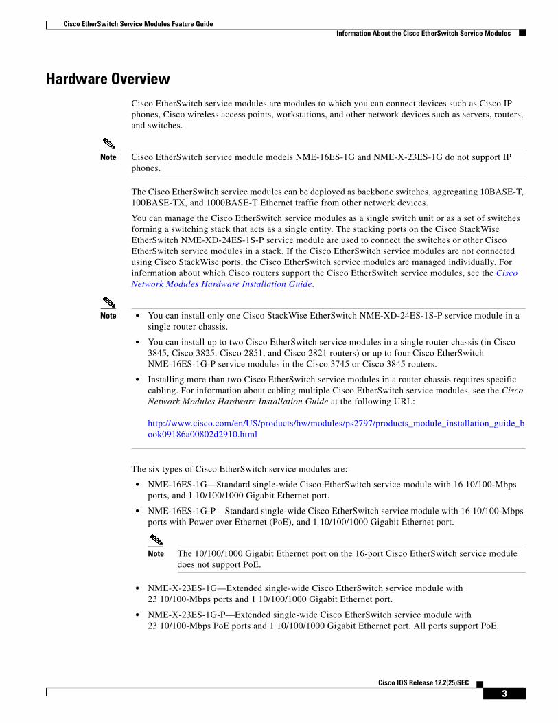
Hardware OverviewCisco EtherSwitch service modules are modules to which you can connect devices such as Cisco IP phones, Cisco wireless access points, workstations, and other network devices such as servers, routers, and switches.
Note Cisco EtherSwitch service module models NME-16ES-1G and NME-X-23ES-1G do not support IP phones.
The Cisco EtherSwitch service modules can be deployed as backbone switches, aggregating 10BASE-T, 100BASE-TX, and 1000BASE-T Ethernet traffic from other network devices.
You can manage the Cisco EtherSwitch service modules as a single switch unit or as a set of switches forming a switching stack that acts as a single entity. The stacking ports on the Cisco StackWise EtherSwitch NME-XD-24ES-1S-P service module are used to connect the switches or other Cisco EtherSwitch service modules in a stack. If the Cisco EtherSwitch service modules are not connected using Cisco StackWise ports, the Cisco EtherSwitch service modules are managed individually. For information about which Cisco routers support the Cisco EtherSwitch service modules, see the Cisco Network Modules Hardware Installation Guide.
Note • You can install only one Cisco StackWise EtherSwitch NME-XD-24ES-1S-P service module in a single router chassis.
• You can install up to two Cisco EtherSwitch service modules in a single router chassis (in Cisco 3845, Cisco 3825, Cisco 2851, and Cisco 2821 routers) or up to four Cisco EtherSwitch NME-16ES-1G-P service modules in the Cisco 3745 or Cisco 3845 routers.
• Installing more than two Cisco EtherSwitch service modules in a router chassis requires specific cabling. For information about cabling multiple Cisco EtherSwitch service modules, see the Cisco Network Modules Hardware Installation Guide at the following URL:
http://www.cisco.com/en/US/products/hw/modules/ps2797/products_module_installation_guide_book09186a00802d2910.html
The six types of Cisco EtherSwitch service modules are:
• NME-16ES-1G—Standard single-wide Cisco EtherSwitch service module with 16 10/100-Mbps ports, and 1 10/100/1000 Gigabit Ethernet port.
• NME-16ES-1G-P—Standard single-wide Cisco EtherSwitch service module with 16 10/100-Mbps ports with Power over Ethernet (PoE), and 1 10/100/1000 Gigabit Ethernet port.
Note The 10/100/1000 Gigabit Ethernet port on the 16-port Cisco EtherSwitch service module does not support PoE.
• NME-X-23ES-1G—Extended single-wide Cisco EtherSwitch service module with 23 10/100-Mbps ports and 1 10/100/1000 Gigabit Ethernet port.
• NME-X-23ES-1G-P—Extended single-wide Cisco EtherSwitch service module with 23 10/100-Mbps PoE ports and 1 10/100/1000 Gigabit Ethernet port. All ports support PoE.
3Cisco IOS Release 12.2(25)SEC

Cisco EtherSwitch Service Modules Feature GuideInformation About the Cisco EtherSwitch Service Modules
• NME-XD-48ES-2S-P—Extended double-wide Cisco EtherSwitch service module with 48 10/100-Mbps PoE ports, and 2 small form-factor pluggable (SFP) Gigabit Ethernet service module ports
• NME-XD-24ES-1S-P—Extended double-wide Cisco EtherSwitch service module with 24 10/100-Mbps PoE ports, 1 SFP port, and 2 Cisco StackWise ports
For complete information about the Cisco EtherSwitch service modules hardware, see the Cisco Network Modules Hardware Installation Guide at the following URL:
http://www.cisco.com/en/US/products/hw/modules/ps2797/products_module_installation_guide_book09186a00802d2910.html
Software Features and BenefitsThe Cisco EtherSwitch service modules are shipped with either of these software images installed:
• IP base image, which provides Layer 2+ features (enterprise-class intelligent services). These features include access control lists (ACLs), quality of service (QoS), static routing, and the Hot Standby Router Protocol (HSRP) and the Routing Information Protocol (RIP). Cisco EtherSwitch service modules with the IP base image installed can be upgraded to the IP services image.
• IP services image, which provides a richer set of enterprise-class intelligent services. It includes all IP base image features plus full Layer 3 routing (IP unicast routing, IP multicast routing, and fallback bridging). To distinguish it from the Layer 2+ static routing and RIP, the IP services image includes protocols such as the Enhanced Interior Gateway Routing Protocol (EIGRP) and the Open Shortest Path First (OSPF) Protocol.
Some features noted in this section are available only on the cryptographic versions of the IP base image and IP services image. You must obtain authorization to use this feature and to download the cryptographic version of the software from Cisco.com.
The Cisco EtherSwitch service module has these features and benefits:
• Ease-of-Use and Ease-of-Deployment Features, page 5
• Performance Features, page 5
• Management Options, page 6
• Manageability Features, page 7
• Availability Features, page 7
• VLAN Features, page 8
• Security Features, page 9
• QoS and CoS Features, page 10
• Power-over-Ethernet Features, page 11
• Monitoring Features, page 11
4Cisco IOS Release 12.2(25)SEC

Cisco EtherSwitch Service Modules Feature GuideInformation About the Cisco EtherSwitch Service Modules
Ease-of-Use and Ease-of-Deployment Features
• Express Setup for quickly configuring a Cisco EtherSwitch service module for the first time with basic IP information, contact information, Cisco EtherSwitch service module and Telnet passwords, and Simple Network Management Protocol (SNMP) information through a browser-based program.
• Graphical user interfaces (GUIs) for easier Cisco EtherSwitch service module configuration and monitoring. For more information about these GUIs, see the “Management Options” section on page 6.
• User-defined and Cisco-default SmartPorts macros for creating custom Cisco EtherSwitch service module configurations for simplified deployment across the network.
• Cisco StackWise technology for these uses:
– Connecting up to nine Cisco EtherSwitch service modules through Cisco StackWise ports and operating as a single switch in the network.
– Using a single IP address and configuration file to manage the entire switch stack.
– Automatic Cisco IOS software version-check of new stack members with the option to automatically load images from the stack master or from a TFTP server.
– Adding, removing, and replacing Cisco EtherSwitch service modules in the stack without disrupting the operation of the stack.
– Provisioning a new member for a switch stack with the offline configuration feature. You can configure the interface configuration for a specific stack member number in advance. The switch stack retains this information across stack reloads whether or not the provisioned Cisco EtherSwitch service module is part of the stack.
– Displaying stack-ring activity statistics (the number of frames sent by each stack member to the ring).
Performance Features
• Autosensing of port speed and autonegotiation of duplex mode on all Cisco EtherSwitch service module ports for optimizing bandwidth
• Automatic-medium-dependent interface crossover (Auto-MDIX) capability on 10/100-Mbps interfaces that enables the interface to automatically detect the required cable connection type (straight-through or crossover) and to configure the connection appropriately
• Up to 32 Gbps of forwarding rates in a switch stack
• EtherChannel for enhanced fault tolerance and for providing up to 800 Mbps (Fast EtherChannel) of full-duplex bandwidth between Cisco EtherSwitch service modules, routers, and servers
• Port Aggregation Protocol (PAgP) and Link Aggregation Control Protocol (LACP) for automatic creation of EtherChannel links
• Forwarding of Layer 2 and Layer 3 packets at gigabit-per-second line rate across the Cisco EtherSwitch service modules in the stack
• Per-port storm control for preventing broadcast, multicast, and unicast storms
• Port blocking on forwarding unknown Layer 2 unknown unicast, multicast, and bridged broadcast traffic
5Cisco IOS Release 12.2(25)SEC
Cisco EtherSwitch Service Modules Feature GuideInformation About the Cisco EtherSwitch Service Modules
• Cisco Group Management Protocol (CGMP) server support and Internet Group Management Protocol (IGMP) snooping for IGMP versions 1, 2, and 3:
– (For CGMP devices) CGMP for limiting multicast traffic to specified end stations and reducing overall network traffic
– (For IGMP devices) IGMP snooping for efficiently forwarding multimedia and multicast traffic
• IGMP report suppression for sending only one IGMP report per multicast router query to the multicast devices (supported only for IGMPv1 or IGMPv2 queries)
• Multicast VLAN registration (MVR) to continuously send multicast streams in a multicast VLAN while isolating the streams from subscriber VLANs for bandwidth and security reasons
• IGMP filtering for controlling the set of multicast groups to which hosts on a Cisco EtherSwitch service module port can belong
• IGMP throttling for configuring the action when the maximum number of entries is in the IGMP forwarding table
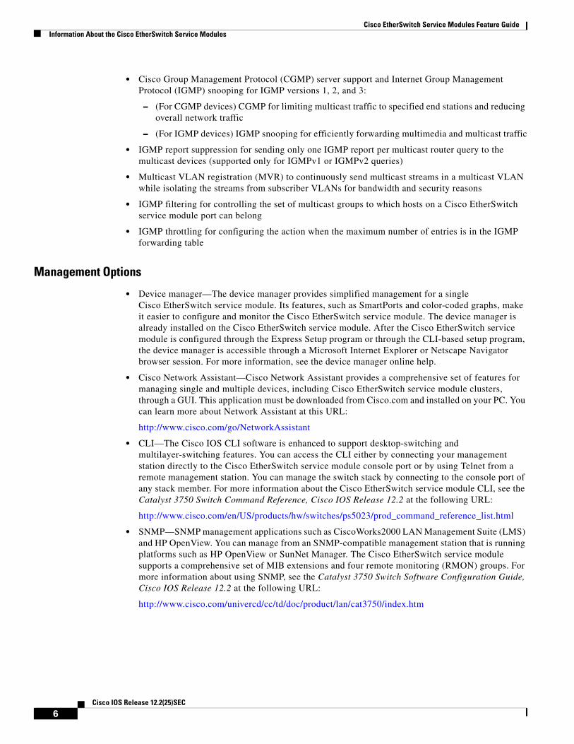
Management Options
• Device manager—The device manager provides simplified management for a single Cisco EtherSwitch service module. Its features, such as SmartPorts and color-coded graphs, make it easier to configure and monitor the Cisco EtherSwitch service module. The device manager is already installed on the Cisco EtherSwitch service module. After the Cisco EtherSwitch service module is configured through the Express Setup program or through the CLI-based setup program, the device manager is accessible through a Microsoft Internet Explorer or Netscape Navigator browser session. For more information, see the device manager online help.
• Cisco Network Assistant—Cisco Network Assistant provides a comprehensive set of features for managing single and multiple devices, including Cisco EtherSwitch service module clusters, through a GUI. This application must be downloaded from Cisco.com and installed on your PC. You can learn more about Network Assistant at this URL:
http://www.cisco.com/go/NetworkAssistant
• CLI—The Cisco IOS CLI software is enhanced to support desktop-switching and multilayer-switching features. You can access the CLI either by connecting your management station directly to the Cisco EtherSwitch service module console port or by using Telnet from a remote management station. You can manage the switch stack by connecting to the console port of any stack member. For more information about the Cisco EtherSwitch service module CLI, see the Catalyst 3750 Switch Command Reference, Cisco IOS Release 12.2 at the following URL:
http://www.cisco.com/en/US/products/hw/switches/ps5023/prod_command_reference_list.html
• SNMP—SNMP management applications such as CiscoWorks2000 LAN Management Suite (LMS) and HP OpenView. You can manage from an SNMP-compatible management station that is running platforms such as HP OpenView or SunNet Manager. The Cisco EtherSwitch service module supports a comprehensive set of MIB extensions and four remote monitoring (RMON) groups. For more information about using SNMP, see the Catalyst 3750 Switch Software Configuration Guide, Cisco IOS Release 12.2 at the following URL:
http://www.cisco.com/univercd/cc/td/doc/product/lan/cat3750/index.htm
6Cisco IOS Release 12.2(25)SEC

Cisco EtherSwitch Service Modules Feature GuideInformation About the Cisco EtherSwitch Service Modules
Manageability Features
Note The encrypted Secure Shell (SSH) feature listed in this section is available only on the cryptographic versions of the Cisco EtherSwitch service module software image.
• Cisco IE 2100 Series CNS embedded agents for automating Cisco EtherSwitch service module management as well as configuration storage and delivery.
• Dynamic Host Configuration Protocol (DHCP) for automating configuration of Cisco EtherSwitch service module information (such as IP address, default gateway, hostname, and Domain Name System [DNS] and Trivial File Transfer Protocol [TFTP] server names)
• DHCP relay agent information (option 82) for subscriber identification and IP address management
• DHCP relay for forwarding User Datagram Protocol (UDP) broadcasts, including IP address requests, from DHCP clients
• DHCP server for automatic assignment of IP addresses and other DHCP options to IP hosts
• Directed unicast requests to a DNS server for identifying a Cisco EtherSwitch service module through its IP address and its corresponding hostname and to a TFTP server for administering software upgrades from a TFTP server
• Address Resolution Protocol (ARP) for identifying a Cisco EtherSwitch service module through its IP address and its corresponding Media Access Control (MAC) address
• Unicast MAC address filtering to drop packets with specific source or destination MAC addresses
• Cisco Discovery Protocol (CDP) versions 1 and 2 for network topology discovery and mapping between the Cisco EtherSwitch service module and other Cisco devices on the network
• Network Time Protocol (NTP) for providing a consistent time stamp to all Cisco EtherSwitch service modules from an external source
• Cisco IOS File System (IFS) for providing a single interface to all file systems that the Cisco EtherSwitch service module uses
• In-band management access for up to 16 simultaneous Telnet connections for multiple CLI-based sessions over the network
• In-band management access for up to five simultaneous, encrypted SSH connections for multiple CLI-based sessions over the network (requires the cryptographic versions of the Cisco EtherSwitch service module software image)
• In-band management access through SNMP versions 1 and 2c, and 3 GET and SET requests
Availability Features
• HSRP for command Cisco EtherSwitch service module and Layer 3 router redundancy.
• Automatic stack master re-election for replacing stack masters that become unavailable (failover support).
The newly elected stack master begins accepting Layer 2 traffic in less than 1 second and Layer 3 traffic between 3 to 5 seconds.
• Cross-stack EtherChannel for providing redundant links across the switch stack.
• UniDirectional Link Detection (UDLD) and aggressive UDLD for detecting and disabling unidirectional links on fiber-optic interfaces caused by incorrect fiber-optic wiring or port faults.
7Cisco IOS Release 12.2(25)SEC

Cisco EtherSwitch Service Modules Feature GuideInformation About the Cisco EtherSwitch Service Modules
• IEEE 802.1D Spanning Tree Protocol (STP) for redundant backbone connections and loop-free networks. STP has these features:
– Up to 128 spanning-tree instances supported.
– Per-VLAN spanning-tree plus (PVST+) for balancing load across VLANs.
– Rapid PVST+ for balancing load across VLANs and providing rapid convergence of spanning-tree instances.
– UplinkFast, cross-stack UplinkFast, and BackboneFast for fast convergence after a spanning-tree topology change and for achieving load balancing between redundant uplinks, including gigabit uplinks and cross-stack gigabit uplinks.
• IEEE 802.1s Multiple Spanning Tree Protocol (MSTP) for grouping VLANs into a spanning-tree instance and for providing multiple forwarding paths for data traffic and load balancing and IEEE 802.1w Rapid Spanning Tree Protocol (RSTP) for rapid convergence of the spanning tree by immediately transitioning root and designated ports to the forwarding state.
• Optional spanning-tree features available in PVST+, rapid PVST+, and MSTP mode:
– Port Fast for eliminating the forwarding delay by enabling a port to immediately transition from the blocking state to the forwarding state.
– BPDU guard for shutting down Port Fast-enabled ports that receive bridge protocol data units (BPDUs).
– BPDU filtering for preventing a Port Fast-enabled port from sending or receiving BPDUs.
– Root guard for preventing switches outside the network core from becoming the spanning-tree root.
– Loop guard for preventing alternative or root ports from becoming designated ports because of a failure that leads to a unidirectional link.
• Equal-cost routing for link-level and Cisco EtherSwitch service module-level redundancy.
• Redundant power supply (RPS) support through the Cisco 2811, 2821, 2851, 3825, and 3845 integrated services routers (ISR). When an AC-IP power supply is installed, RPS is available for ISRs as well as PoE.
VLAN Features
• Support for VLAN IDs in the full 1 to 4094 range allowed by the IEEE 802.1Q standard.
• The VLAN ID to which the port belongs (also known as its VLAN membership). The default is 1 for all ports.
• VLAN Query Protocol (VQP) for dynamic VLAN membership.
• Inter-Switch Link (ISL) and IEEE 802.1Q trunking encapsulation on all ports for network moves, adds, and changes; management and control of broadcast and multicast traffic; and network security by establishing VLAN groups for high-security users and network resources.
• Dynamic Trunking Protocol (DTP) for negotiating trunking on a link between two devices and for negotiating the type of trunking encapsulation (802.1Q or ISL) to be used.
• VLAN Trunking Protocol (VTP) and VTP pruning for reducing network traffic by restricting flooded traffic to links destined for stations receiving the traffic.
8Cisco IOS Release 12.2(25)SEC

Cisco EtherSwitch Service Modules Feature GuideInformation About the Cisco EtherSwitch Service Modules
• Voice VLAN for creating subnets for voice traffic from Cisco IP phones.
• VLAN 1 minimization for reducing the risk of spanning-tree loops or storms by allowing VLAN 1 to be disabled on any individual VLAN trunk link. With this feature enabled, no user traffic is sent or received on the trunk. The Cisco EtherSwitch service module CPU continues to send and receive control protocol frames.
Security Features
Note The Kerberos feature listed in this section is available only on the cryptographic versions of the Cisco EtherSwitch service module software image.
• Password-protected access (read-only and read-write access) to management interfaces for protection against unauthorized configuration changes
• Multilevel security for a choice of security level, notification, and resulting actions
• Static MAC addressing for ensuring security
• Protected port option for restricting the forwarding of traffic to designated ports on the same Cisco EtherSwitch service module
• Port security option for limiting and identifying MAC addresses of the stations allowed to access the port
• Port security aging to set the aging time for secure addresses on a port
• BPDU guard for shutting down a Port Fast-configured port when an invalid configuration occurs
• Standard and extended IP access control lists (ACLs) for defining security policies in both directions on routed interfaces (router ACLs) and VLANs and inbound on Layer 2 interfaces (port ACLs)
• Extended MAC access control lists for defining security policies in the inbound direction on Layer 2 interfaces
• VLAN ACLs (VLAN maps) for providing intra-VLAN security by filtering traffic based on information in the MAC, IP, and TCP/User Datagram Protocol (UDP) headers
• Source and destination MAC-based ACLs for filtering non-IP traffic
• DHCP snooping to filter untrusted DHCP messages between untrusted hosts and DHCP servers
• IEEE 802.1x port-based authentication to prevent unauthorized devices (clients) from gaining access to the network
– 802.1x with VLAN assignment for restricting 802.1x-authenticated users to a specified VLAN
– 802.1x with port security for controlling access to 802.1x ports
– 802.1x with voice VLAN to permit IP phone access to the voice VLAN regardless of the authorized or unauthorized state of the port
– 802.1x with guest VLAN to provide limited services to non-802.1x-compliant users
• TACACS+, a proprietary feature for managing network security through a TACACS server
• RADIUS for verifying the identity of, granting access to, and tracking the actions of remote users through authentication, authorization, and accounting (AAA) services
9Cisco IOS Release 12.2(25)SEC
Cisco EtherSwitch Service Modules Feature GuideInformation About the Cisco EtherSwitch Service Modules
• Kerberos security system to authenticate requests for network resources by using a trusted third party (requires the cryptographic versions of the Cisco EtherSwitch service module software image)
• 802.1Q tunneling to allow customers with users at remote sites across a service provider network to keep VLANs segregated from other customers, and Layer 2 protocol tunneling to ensure that the customer network has complete STP, CDP, and VTP information about all users (available on the Cisco EtherSwitch service module but not on the integrated services router [ISR])
QoS and CoS Features
• Automatic QoS (auto-QoS) to simplify the deployment of existing QoS features by classifying traffic and configuring egress queues (voice over IP only).
• Cross-stack QoS for configuring QoS features on Cisco EtherSwitch service modules in a switch stack rather than on an individual Cisco EtherSwitch service module basis.
• Classification
– Classification on a physical interface or on a per-port per-VLAN basis.
– IP type-of-service/differentiated services code point (IP ToS/DSCP) and 802.1p CoS marking priorities on a per-port basis for protecting the performance of mission-critical applications.
– IP ToS/DSCP and 802.1p CoS marking based on flow-based packet classification (classification based on information in the MAC, IP, and TCP/UDP headers) for high-performance quality of service at the network edge, allowing for differentiated service levels for different types of network traffic and for prioritizing mission-critical traffic in the network.
– Trusted port states (CoS, DSCP, and IP precedence) within a QoS domain and with a port bordering another QoS domain.
– Trusted boundary for detecting the presence of a Cisco IP phone, trusting the CoS value received, and ensuring port security.
• Policing
– Policing on a physical interface or on a per-port per-VLAN basis.
– Traffic-policing policies on the Cisco EtherSwitch service module port for managing how much of the port bandwidth should be allocated to a specific traffic flow.
– Aggregate policing for policing traffic flows in aggregate to restrict specific applications or traffic flows to metered, predefined rates.
• Out-of-profile markdown for packets that exceed bandwidth utilization limits
• Ingress queueing and scheduling
– Two configurable ingress queues for user traffic (one queue can be the priority queue).
– Weighted tail drop (WTD) as the congestion-avoidance mechanism for managing the queue lengths and providing drop precedences for different traffic classifications.
– Shaped round robin (SRR) as the scheduling service for specifying the rate at which packets are dequeued to the stack internal ring (sharing is the only supported mode on ingress queues).
10Cisco IOS Release 12.2(25)SEC

Cisco EtherSwitch Service Modules Feature GuideInformation About the Cisco EtherSwitch Service Modules
• Egress queues and scheduling
– Four egress queues per port.
– WTD as the congestion-avoidance mechanism for managing the queue lengths and providing drop precedences for different traffic classifications.
– SRR as the scheduling service for specifying the rate at which packets are dequeued to the egress interface (shaping or sharing is supported on egress queues). Shaped egress queues are guaranteed but limited to using a share of port bandwidth. Shared egress queues are also guaranteed a configured share of bandwidth, but can use more than the guarantee if other queues become empty and do not use their share of the bandwidth.
Power-over-Ethernet Features
• Ability to provide power to connected Cisco pre-standard and IEEE 802.3af-compliant powered devices from all 10/100-Mbps Ethernet ports if the Cisco EtherSwitch service module detects that there is no power up the circuit
• A 24-port PoE Cisco EtherSwitch service module can provide up to 15.4 W of power on each 10/100-Mbps port. A 48-port PoE Cisco EtherSwitch service module can provide up to 15.4 W of power to any 23 of the 48 10/100-Mbps ports. Any combination of ports can provide up to an average of 7.5 W of power at the same time, depending on the power supply capacity in the router chassis.
Note Total power provided is up to the limit of the platform power supply. PoE requires using the AC+IP power supply (not the default power supply) that was shipped with your router. For information about PoE power requirements, access the Cisco.com web page. Click the Products and Solutions link. From the pull-down menu, click Routers and Routing Systems. Click the router platform on which you will install the Cisco EtherSwitch service module.
Monitoring Features
• Cisco EtherSwitch service module LEDs that provide port-, service module-, and stack-level status
• MAC address notification traps and RADIUS accounting for tracking users on a network by storing the MAC addresses that the Cisco EtherSwitch service module has learned or removed
• Switched Port Analyzer (SPAN) and Remote SPAN (RSPAN) for traffic monitoring on any port or VLAN
• SPAN and RSPAN support of Intrusion Detection Systems (IDS) to monitor, repel, and report network security violations
• Four groups (history, statistics, alarms, and events) of embedded RMON agents for network monitoring and traffic analysis
• Syslog facility for logging system messages about authentication or authorization errors, resource issues, and timeout events
• Layer 2 traceroute to identify the physical path that a packet takes from a source device to a destination device
• Time Domain Reflectometer (TDR) to diagnose and resolve cabling problems on copper Ethernet 10/100/1000-Mbps ports
11Cisco IOS Release 12.2(25)SEC
Cisco EtherSwitch Service Modules Feature GuideInformation About the Cisco EtherSwitch Service Modules
Cisco StackWise ConceptsThis section describes the concepts applicable to switch stacks of Cisco EtherSwitch service modules.
• Overview of Switch Stacks, page 12
• Switch Stack Membership, page 13
• Stack Master Election and Re-Election, page 14
• Switch Stack Bridge ID and Router MAC Address, page 15
• Stack Member Numbers, page 15
• Stack Member Priority Values, page 16
• Switch Stack Software Compatibility Recommendations, page 17
• Stack Protocol Version Compatibility, page 17
• Major Incompatibility Between Cisco EtherSwitch Service Modules, page 17
• Minor Incompatibility Between Cisco EtherSwitch Service Modules, page 18
• Switch Stack Configuration Files, page 18
• Switch Stack Management Connectivity, page 19
• Management Connectivity to the Switch Stack Through an IP Address, page 19
• Management Connectivity to the Switch Stack Through an SSH Session, page 19
• Management Connectivity to the Switch Stack Through Console Ports, page 19
• Management Connectivity to Specific Stack Members, page 20
• Accessing the CLI of a Specific Stack Member, page 20
• Accessing the CLI of a Specific Stack Member, page 20
Overview of Switch Stacks
You can manage the Cisco EtherSwitch service modules as a single unit by connecting them through the StackWise ports of a 24-port Cisco StackWise EtherSwitch service module, and managing the switch stack through a Cisco router. For information about which Cisco routers support the Cisco EtherSwitch service modules, see the Cisco Network Modules Hardware Installation Guide.
Note • You can install only one Cisco StackWise EtherSwitch NME-XD-24ES-1S-P service module in a single router chassis.
• You can install up to two Cisco EtherSwitch service modules in a Cisco 3845, Cisco 3825, Cisco 2851, or Cisco 2821 router or up to four Cisco EtherSwitch NME-16ES-1G-P service modules in the Cisco 3745 or Cisco 3845 routers.
• Installing more than two Cisco EtherSwitch service modules in a router chassis requires specific cabling. For information about cabling multiple Cisco EtherSwitch service modules, see the Cisco Network Modules Hardware Installation Guide at the following URL:
http://www.cisco.com/en/US/products/hw/modules/ps2797/products_module_installation_guide_book09186a00802d2910.html
12Cisco IOS Release 12.2(25)SEC
Cisco EtherSwitch Service Modules Feature GuideInformation About the Cisco EtherSwitch Service Modules
A switch stack is a set of Cisco EtherSwitch service modules or Catalyst 3750 switches connected through their Cisco StackWise ports. One of the Cisco EtherSwitch service modules or one of the Catalyst 3750 switches controls the operation of the stack and is called the stack master. The stack master and the other Cisco EtherSwitch service modules or Catalyst 3750 switches in the stack are stack members. The stack members use the Cisco StackWise technology to behave and work together as a unified system. Layer 2 and Layer 3 protocols present the entire switch stack as a single entity to the network.
The stack master is the single point of stack-wide management. From the stack master, you configure:
• System-level (global) features that apply to all stack members
• Interface-level features for each stack member
A switch stack is identified in the network by its bridge ID and, if the switch stack is operating as a Layer 3 device, its router MAC address. The bridge ID and router MAC address are determined by the MAC address of the stack master. Every stack member is uniquely identified by its own stack member number.
All stack members are eligible stack masters. If the stack master becomes unavailable, the remaining stack members participate in electing a new stack master from among themselves. A set of factors determine which Cisco EtherSwitch service module or Catalyst 3750 switch is elected the stack master. One of the factors is the stack member priority value. The internal interface with the highest-priority value becomes the stack master.
Note The system-level features supported on the stack master are supported on the entire switch stack. If the switch stack must have Cisco EtherSwitch service modules or Catalyst 3750 switches running both IP base image and IP services image, we recommend that a member running the IP services image be the stack master. IP services image features are unavailable if the stack master is running the IP base image.
Similarly, we recommend that a Cisco EtherSwitch service module or Catalyst 3750 switch running the cryptographic version of the IP base image or IP services image be the stack master. Encryption features are unavailable if the stack master is running the noncryptographic version of the IP base image or IP services image.
The stack master contains the saved and running configuration files for the switch stack. The configuration files include the system-level settings for the switch stack and the interface-level settings for each stack member. Each stack member has a current copy of these files for backup purposes.
You manage the switch stack through a single IP address. The IP address is a system-level setting and is not specific to the stack master or to any other stack member. You can manage the stack through the same IP address even if you remove the stack master or any other stack member from the stack.
You can use these methods to manage switch stacks:
• Using the command-line interface (CLI) and the session command
• Using a network management application through Simple Network Management Protocol (SNMP)
• Using the CiscoWorks network management software
Switch Stack Membership
A switch stack has up to nine stack members connected through their StackWise ports. A switch stack always has one stack master.
13Cisco IOS Release 12.2(25)SEC

Cisco EtherSwitch Service Modules Feature GuideInformation About the Cisco EtherSwitch Service Modules
A standalone Cisco EtherSwitch service module or Catalyst 3750 switch is a switch stack with one stack member that also operates as the stack master. You can connect one standalone Cisco EtherSwitch service module to another Cisco EtherSwitch service module or Catalyst 3750 switch to create a switch stack containing two stack members, with one of them being the stack master. You can connect standalone modules to an existing switch stack to increase the stack membership.
If you replace a stack member with an identical model, the new Cisco EtherSwitch service module or Catalyst 3750 switch functions with exactly the same configuration as the replaced Cisco EtherSwitch service module, assuming that the new Cisco EtherSwitch service module or switch is using the same member number as the replaced Cisco EtherSwitch service module or switch.
The operation of the switch stack continues uninterrupted during membership changes unless you remove the stack master or you add powered-up standalone Cisco EtherSwitch service modules or switches.
Note • Make sure the Cisco EtherSwitch service modules or Catalyst 3750 switches that you add to or remove from the switch stack are powered off.
• After adding or removing stack members, make sure that the switch stack is operating at full bandwidth (32 Gbps). Press the Mode button on a stack member until the Stack mode LED is on. The last two port LEDs on all Cisco EtherSwitch service modules in the stack should be green. Depending on the Cisco EtherSwitch service module model, the last two ports are either 10/100/1000-Mbps ports or small form-factor pluggable (SFP) service module ports. If, on any of the modules, one or both of the last two port LEDs are not green, the stack is not operating at full bandwidth.
Adding powered-up modules (merging) causes the stack masters of the merging Cisco EtherSwitch service module stacks to elect a stack master from among themselves. The re-elected stack master retains its role and configuration and so do its stack members. All remaining modules, including the former stack masters, reload and join the switch stack as stack members. They change their stack member numbers to the lowest available numbers and use the stack configuration of the re-elected stack master.
Stack Master Election and Re-Election
The stack master is elected or re-elected based on one of these factors and in the order listed:
1. The Cisco EtherSwitch service module or Catalyst 3750 switch currently the stack master
2. The Cisco EtherSwitch service module or Catalyst 3750 switch with the highest stack member priority value
Note We recommend assigning the highest-priority value to the Cisco EtherSwitch service module or Catalyst 3750 switch that you prefer to be the stack master. This ensures that the Cisco EtherSwitch service module or Catalyst 3750 switch is re-elected as stack master if a re-election occurs.
3. The Cisco EtherSwitch service module or Catalyst 3750 switch not using the default interface-level configuration
4. The Cisco EtherSwitch service module or Catalyst 3750 switch with the higher-priority service module or switch version
14Cisco IOS Release 12.2(25)SEC

Cisco EtherSwitch Service Modules Feature GuideInformation About the Cisco EtherSwitch Service Modules
The Cisco EtherSwitch service module or switch using the versions listed below are ordered from highest to lowest priority:
– Cryptographic IP services image
– Noncryptographic IP services image
– Cryptographic IP base image
– Noncryptographic IP base image
5. The Cisco EtherSwitch service module or switch with the longest system uptime
6. The service module or switch with the lowest MAC address
A stack master retains its role unless one of these events occurs:
• The switch stack is reset.*
• The stack master is removed from the switch stack.
• The stack master is reset or powered off.
• The stack master has failed.
• The switch stack membership is increased by adding powered-up standalone modules or switch stacks.*
In the events marked by an asterisk (*), the current stack master might be re-elected based on the listed factors.
When you power up or reset an entire switch stack, some stack members might not participate in the stack master election. Stack members that are powered up within the same 10-second timeframe participate in the stack master election and have a chance to become the stack master. Stack members that are powered up after the 10-second timeframe do not participate in this initial election and only become stack members. All stack members participate in re-elections.
The new stack master becomes available after a few seconds. In the meantime, the switch stack uses the forwarding tables in memory to minimize network disruption. The physical interfaces on the other available stack members are not affected while a new stack master is elected and is resetting.
If a new stack master is elected and the previous stack master becomes available, the previous stack master does not resume its role as stack master.
You can use the Master LED on the Cisco EtherSwitch service module to see if the service module is the stack master.
Switch Stack Bridge ID and Router MAC Address
The bridge ID and router MAC address identify the switch stack in the network. When the switch stack initializes, the MAC address of the stack master determines the bridge ID and router MAC address.
If the stack master changes, the MAC address of the new stack master determines the new bridge ID and router MAC address.
Stack Member Numbers
The stack member number (1 to 9) identifies each member in the switch stack. The member number also determines the interface-level configuration that a stack member uses. You can display the stack member number by using the show switch user EXEC command.
15Cisco IOS Release 12.2(25)SEC

Cisco EtherSwitch Service Modules Feature GuideInformation About the Cisco EtherSwitch Service Modules
A new, out-of-the-box Cisco EtherSwitch service module (one that has not joined a switch stack or has not been manually assigned a stack member number) ships with a default stack member number of 1. When it joins a switch stack, its default stack member number changes to the lowest available member number in the stack.
Stack members in the same switch stack cannot have the same stack member number. Every stack member, including a standalone Cisco EtherSwitch service module, retains its member number until you manually change the number or unless the number is already being used by another member in the stack.
• If you manually change the stack member number by using the switch current-stack-member-number renumber new-stack-member-number global configuration command, the new number goes into effect after that stack member resets (or after you use the reload slot stack-member-number privileged EXEC command) and only if that number is not already assigned to any other members in the stack. Another way to change the stack member number is by changing the SWITCH_NUMBER environment variable.
If the number is being used by another member in the stack, the Cisco EtherSwitch service module or switch selects the lowest available number in the stack.
Note If you manually change the number of a stack member and no interface-level configuration is associated with that new member number, that stack member resets to its default configuration. For more information about stack member numbers and configurations, see the “Switch Stack Configuration Files” section on page 18.
• If you move a stack member to a different switch stack, the stack member retains its number only if the number is not being used by another member in the stack. If it is being used by another member in the stack, the Cisco EtherSwitch service module or switch selects the lowest available number in the stack.
• If you merge switch stacks, the modules that join the switch stack of a new stack master select the the lowest available numbers in the stack. For more information about merging switch stacks, see the “Accessing the CLI of a Specific Stack Member” section on page 20.
Stack Member Priority Values
A higher-priority value for a stack member increases its likelihood to be elected stack master and to retain its stack member number. The priority value can be 1 to 15. The default priority value is 1. You can display the stack member priority value by using the show switch user EXEC command.
Note We recommend assigning the highest-priority value to the Cisco EtherSwitch service module or switch that you prefer to be the stack master. This ensures that the Cisco EtherSwitch service module is re-elected as stack master if a re-election occurs.
You can change the priority value for a stack member by using the switch stack-member-number priority priority-number global configuration command. Another way to change the member priority value is by changing the SWITCH_PRIORITY environment variable.
The new priority value takes effect immediately but does not affect the current stack master. The new priority value helps determine which stack member is elected as the new stack master when the current stack master or the switch stack resets.
16Cisco IOS Release 12.2(25)SEC

Cisco EtherSwitch Service Modules Feature GuideInformation About the Cisco EtherSwitch Service Modules
Switch Stack Software Compatibility Recommendations
All stack members must run the same Cisco IOS software version to ensure compatibility between stack members.
We recommend the following:
• The Cisco IOS software version on all stack members, including the stack master, should be the same. This helps ensure full compatibility in the stack protocol version among the stack members.
• If your switch stack must have Cisco EtherSwitch service modules or switches running IP base images and IP services images, the Cisco EtherSwitch service module running the IP services image should be the stack master. IP services image features become unavailable to all stack members if the stack master is running the IP base image.
• At least two stack members should have the IP services image installed to ensure redundant support of the IP services image features. The IP services image has precedence over the IP base image during stack master election, assuming that the priority value of the stack members is the same. If the stack master running the IP services image fails, the other stack member running the IP services image becomes the stack master.
• When a Cisco EtherSwitch service module or switch running the IP services image joins a switch stack running the IP base image of the same version, the IP services image Cisco EtherSwitch service module or switch does not automatically become the stack master. If you want the Cisco EtherSwitch service module running the IP services image to become the stack master, reset the current stack master running the IP base image by using the reload slot stack-member-number privileged EXEC command. The Cisco EtherSwitch service module running the IP services image is elected the stack master, assuming its priority value is higher or the same as that of the other stack members.
Stack Protocol Version Compatibility
Each software image includes a stack protocol version. The stack protocol version has a major version number and a minor version number. Both version numbers determine the level of compatibility among the stack members. You can display the stack protocol version by using the show platform stack-manager all privileged EXEC command.
Cisco EtherSwitch service modules or switches with the same Cisco IOS software version have the same stack protocol version. Such modules are fully compatible, and all features function properly across the switch stack. Cisco EtherSwitch service modules or switches with the same Cisco IOS software version as the stack master join the switch stack immediately.
If an incompatibility exists, the incompatible stack members generate a system error message that describes the cause of the incompatibility on the specific stack members. The stack master displays the error message to all stack members.
These sections provide more detail about incompatibility in switch stacks:
• Major Incompatibility Between Cisco EtherSwitch Service Modules, page 17
• Minor Incompatibility Between Cisco EtherSwitch Service Modules, page 18
Major Incompatibility Between Cisco EtherSwitch Service Modules
Cisco EtherSwitch service modules or Catalyst 3750 switches with different Cisco IOS software versions most likely have different stack protocol versions. Cisco EtherSwitch service modules or Catalyst 3750 switches with different major stack protocol version numbers are incompatible and cannot exist in the same switch stack.
17Cisco IOS Release 12.2(25)SEC
Cisco EtherSwitch Service Modules Feature GuideInformation About the Cisco EtherSwitch Service Modules
Minor Incompatibility Between Cisco EtherSwitch Service Modules
Cisco EtherSwitch service modules or Catalyst 3750 switches with the same major version number but a different minor version number as the stack master are considered partially compatible. When connected to a switch stack, partially compatible modules enter into version mismatch (VM) mode and cannot join the stack. The stack master downloads the software version it is using to any Cisco EtherSwitch service module in VM mode.
• If there is a stack member that is not in VM mode and is running software that can also run on the Cisco EtherSwitch service module or Catalyst 3750 switch in VM mode, the stack master uses that software to upgrade (or downgrade) the software on the Cisco EtherSwitch service module or switch in VM mode. The Cisco EtherSwitch service module or switch in VM mode automatically reloads and joins the stack as a fully functioning member.
Note The stack master does not automatically install the IP services image on a Cisco EtherSwitch service module or switch running an IP base image or an IP base image on a Cisco EtherSwitch service module or switch running an IP services image.
• If none of the stack members are running software that can be installed on the Cisco EtherSwitch service module or switch in VM mode, the stack master scans the switch stack to see if there are any other recommended actions. Recommended actions appear in the system messages log. If there are no other actions to try, the stack master displays the recommended action to upgrade the software running on the switch stack.
The port LEDs on Cisco EtherSwitch service modules or switches in VM mode remain off, and pressing the Mode button does not change the LED mode.
You can also use the show switch privileged EXEC command to see if any stack members are in VM mode.
Switch Stack Configuration Files
The configuration files record the following items:
• System-level (global) configuration settings—such as IP, STP, VLAN, and SNMP settings—that apply to all stack members
• Stack member interface-specific configuration settings, which are specific for each stack member
The stack master has the saved and running configuration files for the switch stack. All stack members periodically receive synchronized copies of the configuration files from the stack master. If the stack master becomes unavailable, any stack member assuming the role of stack master has the latest configuration files.
Note We recommend that all stack members have Cisco IOS Release 12.1(14)EA1 or later installed to ensure that the interface-specific settings of the stack master are saved in case the stack master is replaced and the running configuration is not saved to the startup configuration.
When a new, out-of-box Cisco EtherSwitch service module or switch joins a switch stack, it uses the system-level settings of that switch stack. If a Cisco EtherSwitch service module or switch is moved to a different switch stack, that Cisco EtherSwitch service module loses its saved configuration file and uses the system-level configuration of the new switch stack.
18Cisco IOS Release 12.2(25)SEC

Cisco EtherSwitch Service Modules Feature GuideInformation About the Cisco EtherSwitch Service Modules
The interface-specific configuration of each stack member is associated with the stack member number. As mentioned in the “Stack Member Numbers” section on page 15, stack members retain their numbers unless they are manually changed or they are already used by another member in the same switch stack.
• If an interface-specific configuration does not exist for that member number, the stack member uses its default interface-specific configuration.
• If an interface-specific configuration exists for that member number, the stack member uses the interface-specific configuration associated with that member number.
If a stack member fails and you replace it with an identical model, the replacement Cisco EtherSwitch service module or switch automatically uses the same interface-specific configuration as the failed Cisco EtherSwitch service module. Hence, you do not need to reconfigure the interface settings. The replacement Cisco EtherSwitch service module or switch must have the same stack member number as the failed Cisco EtherSwitch service module.
You back up and restore the stack configuration in the same way as you would for a standalone Cisco EtherSwitch service module or switch configuration.
Switch Stack Management Connectivity
You manage the switch stack and the stack member interfaces through the stack master. You can use Network Assistant, the CLI, and SNMP and CiscoWorks network management applications. You cannot manage stack members on an individual Cisco EtherSwitch service module or switch basis.
Management Connectivity to the Switch Stack Through an IP Address
The switch stack is managed through a single IP address. The IP address is a system-level setting and is not specific to the stack master or to any other stack member. You can still manage the stack through the same IP address even if you remove the stack master or any other stack member from the stack, provided there is IP connectivity.
Note Stack members retain their IP addresses when you remove them from a switch stack. To avoid a conflict by having two devices with the same IP address in your network, change the IP address or addresses of the Cisco EtherSwitch service module or switch that you removed from the switch stack.
For related information about switch stack configurations, see the “Switch Stack Configuration Files” section on page 18.
Management Connectivity to the Switch Stack Through an SSH Session
SSH connectivity to the switch stack can be lost if a stack master running the cryptographic version of the IP base image or IP services image fails and is replaced by a Cisco EtherSwitch service module or switch that is running a noncryptographic version of the image. We recommend that a Cisco EtherSwitch service module or switch running the cryptographic version of the IP base image or IP services image be the stack master. Encryption features are unavailable if the stack master is running the noncryptographic version of the IP base image or IP services image.
Management Connectivity to the Switch Stack Through Console Ports
You can connect to the stack master through the console port of one or more stack members.
19Cisco IOS Release 12.2(25)SEC
Cisco EtherSwitch Service Modules Feature GuideInformation About the Cisco EtherSwitch Service Modules
Be careful when using multiple CLI sessions to the stack master. Commands that you enter in one session are not displayed in the other sessions. Therefore, it is possible that you might not be able to identify the session from which you entered a command.
Note We recommend using only one CLI session when you manage the switch stack.
Management Connectivity to Specific Stack Members
If you want to configure a specific stack member port, you must include the stack member number in the CLI command interface notation. For more information about interface notations, see the “Using Interface Configuration Mode” section on page 35.
To debug a specific stack member, you can access it from the stack master by using the session stack-member-number privileged EXEC command. The stack member number is appended to the system prompt. For example, Switch-2# is the prompt in privileged EXEC mode for stack member 2, and the system prompt for the stack master is Switch. Only the show and debug commands are available in a CLI session to a specific stack member.
Accessing the CLI of a Specific Stack Member
Note This task is available only from the stack master. This task is only for debugging purposes.
You can access all or specific stack members by using the remote command {all | stack-member-number} privileged EXEC command. The stack member number range is 1 to 9.
Clustering ConceptsThis section describes the concepts and procedures required to plan and create clusters on a Cisco EtherSwitch service module.
• Cluster Compatibility, page 21
• Command Device Characteristics, page 21
• Standby Command Device Characteristics, page 21
• Candidate and Member Characteristics, page 22
• Automatic Discovery of Candidates and Members, page 22
• Discovery of Candidates and Members Through CDP Hops, page 22
• Discovery of Candidates and Members Through Non-CDP-Capable and Noncluster-Capable Devices, page 23
• Discovery of Candidates and Members Through Different VLANs, page 24
• Discovery of Candidates and Members Through Different Management VLANs, page 24
• Discovery of Candidates and Members Through Routed Ports, page 25
• Discovery of Newly Installed Switches in Clusters, page 26
• HSRP and Standby Cluster Command Switches, page 27
• Virtual IP Addresses in Clusters, page 28
20Cisco IOS Release 12.2(25)SEC

Cisco EtherSwitch Service Modules Feature GuideInformation About the Cisco EtherSwitch Service Modules
• Other Considerations for Cluster Standby Groups, page 28
• Automatic Recovery of Cluster Configuration, page 29
• IP Addresses in Clusters, page 30
• Hostnames in Clusters, page 30
• Passwords in Clusters, page 31
• SNMP Community Strings in Clusters, page 31
• Switch Clusters and Switch Stacks, page 31
• TACACS+ and RADIUS in Clusters, page 33
• Availability of Switch-Specific Features in Switch Clusters, page 33
Cluster Compatibility
When creating a device cluster or adding a devices to a cluster, follow these guidelines:
• When you create a device cluster, we recommend configuring the highest-end device in your cluster as the cluster command switch.
• If you are managing the cluster through Network Assistant, the device that has the latest software should be the cluster command switch.
• The standby cluster command switch must be the same type as the command device. For example, if the command device is a Cisco EtherSwitch service module, all standby command devices must be either Cisco EtherSwitch service modules or Catalyst 3750 switches.
Command Device Characteristics
A command device must meet these requirements:
• It has an IP address.
• Clustering and the HTTP server are enabled (the default).
• CDP version 2 is enabled (the default).
• It is not a command device or a member in another cluster.
• It is connected to standby command devices through the management VLAN and to cluster members through a common VLAN.
Standby Command Device Characteristics
A standby command device must meet these requirements:
• It has an IP address.
• It has CDP version 2 enabled.
• It is connected to the command device and to other standby command devices through its management VLAN.
• It is connected to all other cluster members through a common VLAN.
• It is redundantly connected to the cluster so that connectivity to members is maintained.
• It is not a command device or a member in another cluster.
21Cisco IOS Release 12.2(25)SEC
Cisco EtherSwitch Service Modules Feature GuideInformation About the Cisco EtherSwitch Service Modules
If you want to maintain the same level of feature support when a standby command device takes over, it should run the same release of Cisco IOS software that the command device runs.
Candidate and Member Characteristics
Candidates are cluster-capable devices that have not yet been added to a cluster. Members are devices that have actually been added to a cluster. Although not required, a candidate or member can have its own IP address and password.
To join a cluster, a candidate must meet these requirements:
• It is running cluster-capable software.
• It has CDP version 2 enabled.
• It is not a command device or a member of another cluster.
• If a standby group exists, it is connected to every standby command device through at least one common VLAN. The VLAN to each standby command device can be different.
• It is connected to the command device through at least one common VLAN.
Automatic Discovery of Candidates and Members
The command device uses CDP to discover members, candidates, neighboring clusters, and edge devices across multiple VLANs and in star or cascaded topologies.
Note Do not disable CDP on the command device, members, or any cluster-capable devices that you might want a command device to discover.
Discovery of Candidates and Members Through CDP Hops
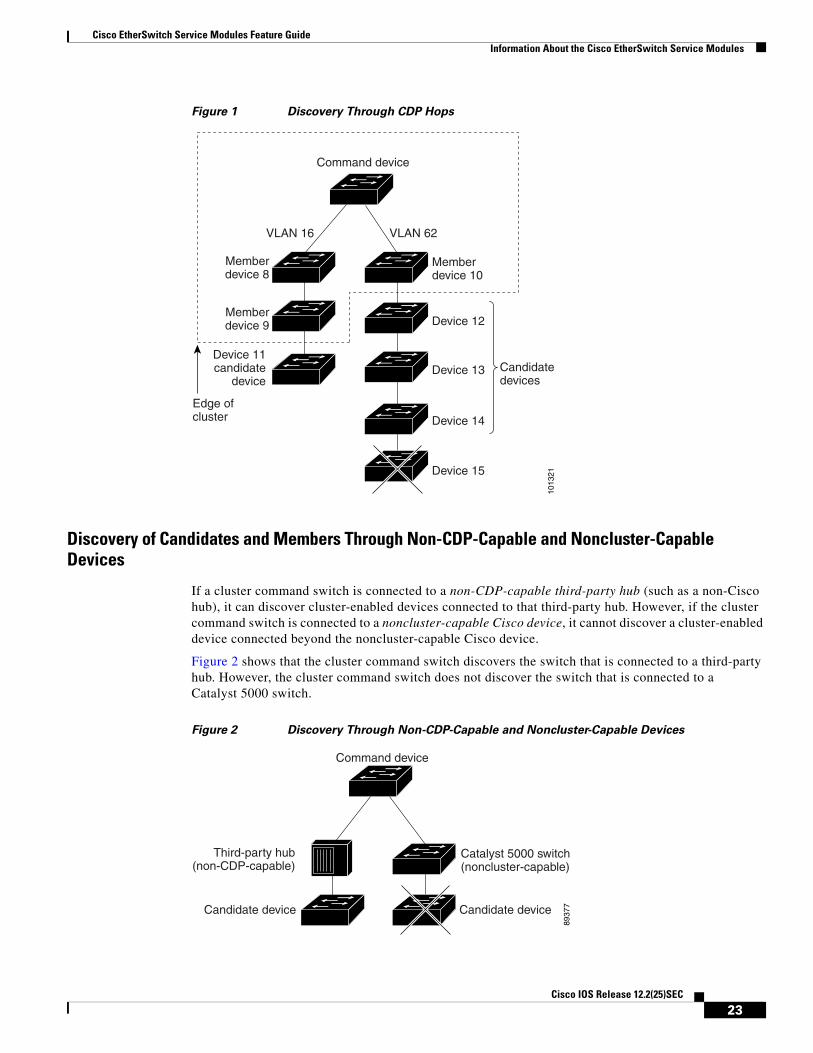
By using CDP, a cluster command switch can discover switches up to seven CDP hops away (the default is three hops) from the edge of the cluster. The last cluster member switches are connected to the cluster and to candidate switches at the edge of the cluster. For example, cluster member switches 9 and 10 in Figure 1 are at the edge of the cluster.
You can set the number of hops that the cluster command switch searches for candidate and cluster member switches by choosing Cluster > Hop Count. When new candidate switches are added to the network, the cluster command switch discovers them and adds them to the list of candidate switches.
Note A switch stack in a cluster equates to a single cluster member switch. There is a restriction specific to adding cluster members through Network Assistant. For more information, see the “Switch Clusters and Switch Stacks” section on page 31.
In Figure 1, the cluster command switch has ports assigned to VLANs 16 and 62. The CDP hop count is three. The cluster command switch discovers switches 11, 12, 13, and 14 because they are within three hops from the edge of the cluster. It does not discover switch 15 because it is four hops from the edge of the cluster.
22Cisco IOS Release 12.2(25)SEC
Cisco EtherSwitch Service Modules Feature GuideInformation About the Cisco EtherSwitch Service Modules
Figure 1 Discovery Through CDP Hops
Discovery of Candidates and Members Through Non-CDP-Capable and Noncluster-Capable Devices
If a cluster command switch is connected to a non-CDP-capable third-party hub (such as a non-Cisco hub), it can discover cluster-enabled devices connected to that third-party hub. However, if the cluster command switch is connected to a noncluster-capable Cisco device, it cannot discover a cluster-enabled device connected beyond the noncluster-capable Cisco device.
Figure 2 shows that the cluster command switch discovers the switch that is connected to a third-party hub. However, the cluster command switch does not discover the switch that is connected to a Catalyst 5000 switch.
Figure 2 Discovery Through Non-CDP-Capable and Noncluster-Capable Devices
Command device
Memberdevice 10
Memberdevice 8
Memberdevice 9
VLAN 62
Edge ofcluster
VLAN 16
1013
21
Device 11candidate
deviceCandidatedevices
Device 12
Device 13
Device 14
Device 15
Command device
Catalyst 5000 switch(noncluster-capable)
Third-party hub(non-CDP-capable)
Candidate device Candidate device
8937
7
23Cisco IOS Release 12.2(25)SEC
Cisco EtherSwitch Service Modules Feature GuideInformation About the Cisco EtherSwitch Service Modules
Discovery of Candidates and Members Through Different VLANs
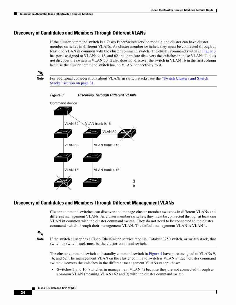
If the cluster command switch is a Cisco EtherSwitch service module, the cluster can have cluster member switches in different VLANs. As cluster member switches, they must be connected through at least one VLAN in common with the cluster command switch. The cluster command switch in Figure 3 has ports assigned to VLANs 9, 16, and 62 and therefore discovers the switches in those VLANs. It does not discover the switch in VLAN 50. It also does not discover the switch in VLAN 16 in the first column because the cluster command switch has no VLAN connectivity to it.
Note For additional considerations about VLANs in switch stacks, see the “Switch Clusters and Switch Stacks” section on page 31.
Figure 3 Discovery Through Different VLANs
Discovery of Candidates and Members Through Different Management VLANs
Cluster command switches can discover and manage cluster member switches in different VLANs and different management VLANs. As cluster member switches, they must be connected through at least one VLAN in common with the cluster command switch. They do not need to be connected to the cluster command switch through their management VLAN. The default management VLAN is VLAN 1.
Note If the switch cluster has a Cisco EtherSwitch service module, Catalyst 3750 switch, or switch stack, that switch or switch stack must be the cluster command switch.
The cluster command switch and standby command switch in Figure 4 have ports assigned to VLANs 9, 16, and 62. The management VLAN on the cluster command switch is VLAN 9. Each cluster command switch discovers the switches in the different management VLANs except these:
• Switches 7 and 10 (switches in management VLAN 4) because they are not connected through a common VLAN (meaning VLANs 62 and 9) with the cluster command switch
VLAN 62
VLAN 62
VLAN 16
VLAN trunk 9,16
Command device
VLAN 50
VLAN trunk 9,16
VLAN trunk 4,16
1013
22
24Cisco IOS Release 12.2(25)SEC

Cisco EtherSwitch Service Modules Feature GuideInformation About the Cisco EtherSwitch Service Modules
• Switch 9 because automatic discovery does not extend beyond a noncandidate device, which is switch 7
Figure 4 Discovery Through Different Management VLANs with a Layer 3 Cluster Command
Switch
Discovery of Candidates and Members Through Routed Ports
If the cluster command switch has a routed port (RP) configured, it discovers only candidate and cluster member switches in the same VLAN as the routed port.
The Layer 3 cluster command switch in Figure 5 can discover the switches in VLANs 9 and 62 but not the switch in VLAN 4. If the routed port path between the cluster command switch and cluster member switch 7 is lost, connectivity with cluster member switch 7 is maintained because of the redundant path through VLAN 9.
1013
23
VLAN 62
VLAN trunk 4, 62
VLAN 62
VLAN 16
VLAN 9
VLAN 16 VLAN 9
Standby commanddevice
Commanddevice
VLAN 9
Device 7(managementVLAN 4)
Device 9(managementVLAN 62)
VLAN 4
Device 3(management
VLAN 16)
Device 4(management
VLAN 16)
Device 10(managementVLAN 4)
Device 8(managementVLAN 9)
Device 6(managementVLAN 9)
Device 5(managementVLAN 62)
25Cisco IOS Release 12.2(25)SEC

Cisco EtherSwitch Service Modules Feature GuideInformation About the Cisco EtherSwitch Service Modules
Figure 5 Discovery Through Routed Ports
Discovery of Newly Installed Switches in Clusters
To join a cluster, the new, out-of-the-box switch must be connected to the cluster through one of its access ports. An access port (AP) carries the traffic of and belongs to only one VLAN. By default, the new switch and its access ports are assigned to VLAN 1.
When the new switch joins a cluster, its default VLAN changes to the VLAN of the immediately upstream neighbor. The new switch also configures its access port to belong to the VLAN of the immediately upstream neighbor.
The cluster command switch in Figure 6 belongs to VLANs 9 and 16. When new cluster-capable switches join the cluster, the following things happen:
• One cluster-capable switch and its access port are assigned to VLAN 9.
• The other cluster-capable switch and its access port are assigned to management VLAN 16.
Figure 6 Discovery of Newly Installed Switches
1013
24
RPRP
VLAN 62
VLAN9
VLAN 62
VLAN 9
VLAN 4
VLAN 9
Command device
(managementVLAN 62)
Memberdevice 7
Command device
New (out-of-box)candidate device
AP
Device A Device B
VLAN 9
VLAN 9
VLAN 16
VLAN 16
New (out-of-box)candidate device
AP
1013
25
26Cisco IOS Release 12.2(25)SEC
Cisco EtherSwitch Service Modules Feature GuideInformation About the Cisco EtherSwitch Service Modules
HSRP and Standby Cluster Command Switches
The switch supports Hot Standby Router Protocol (HSRP) so that you can configure a group of standby cluster command switches. Because a cluster command switch manages the forwarding of all communication and configuration information to all the cluster member switches, we strongly recommend the following:
• For a cluster command switch stack, a standby cluster command switch is necessary if the entire switch stack fails. However, if only the stack master in the command switch stack fails, the switch stack elects a new stack master and resumes its role as the cluster command switch stack.
• For a cluster command switch that is a standalone switch, configure a standby cluster command switch to take over if the primary cluster command switch fails.
A cluster standby group is a group of command-capable switches that meet the requirements described in the “Standby Command Device Characteristics” section on page 21. Only one cluster standby group can be assigned per cluster.
Note If the switch cluster has a Cisco EtherSwitch service module, Catalyst 3750 switch, or switch stack, that switch or switch stack must be the cluster command switch.
Note The cluster standby group is an HSRP group. Disabling HSRP disables the cluster standby group.
• The switches in the cluster standby group are ranked according to HSRP priorities. The switch with the highest priority in the group is the active cluster command switch (AC). The switch with the next highest priority is the standby cluster command switch (SC). The other switches in the cluster standby group are the passive cluster command switches (PC). If the active cluster command switch and the standby cluster command switch become disabled at the same time, the passive cluster command switch with the highest priority becomes the active cluster command switch. For the limitations to automatic discovery, see the “Automatic Recovery of Cluster Configuration” section on page 29. For information about changing HSRP priority values, see the Catalyst 3750 Switch Software Configuration Guide, Cisco IOS Release 12.2 at http://www.cisco.com/univercd/cc/td/doc/product/lan/cat3750/index.htm. The HSRP standby priority interface configuration commands are the same for changing the priority of cluster standby group members and router-redundancy group members.
Note The HSRP standby hold time interval should be greater than or equal to three times the hello time interval. The default HSRP standby hold time interval is 10 seconds. The default HSRP standby hello time interval is 3 seconds. For more information about the standby hold time and standby hello time intervals, see the Catalyst 3750 Switch Software Configuration Guide, Cisco IOS Release 12.2 at http://www.cisco.com/univercd/cc/td/doc/product/lan/cat3750/index.htm.
These connectivity guidelines ensure automatic discovery of the switch cluster, cluster candidates, connected switch clusters, and neighboring edge devices. These topics also provide more detail about standby cluster command switches:
• Virtual IP Addresses in Clusters, page 28
• Other Considerations for Cluster Standby Groups, page 28
• Automatic Recovery of Cluster Configuration, page 29
27Cisco IOS Release 12.2(25)SEC

Cisco EtherSwitch Service Modules Feature GuideInformation About the Cisco EtherSwitch Service Modules
Virtual IP Addresses in Clusters
You need to assign a unique virtual IP address and group number and name to the cluster standby group. This information must be configured on a specific VLAN or routed port on the active cluster command switch. The active cluster command switch receives traffic destined for the virtual IP address. To manage the cluster, you must access the active cluster command switch through the virtual IP address, not through the command-switch IP address. This is in case the IP address of the active cluster command switch is different from the virtual IP address of the cluster standby group.
If the active cluster command switch fails, the standby cluster command switch assumes ownership of the virtual IP address and becomes the active cluster command switch. The passive switches in the cluster standby group compare their assigned priorities to decide the new standby cluster command switch. The passive standby switch with the highest priority then becomes the standby cluster command switch. When the previously active cluster command switch becomes active again, it resumes its role as the active cluster command switch, and the current active cluster command switch becomes the standby cluster command switch again. For more information about IP address in switch clusters, see the “IP Addresses in Clusters” section on page 30.
Other Considerations for Cluster Standby Groups
Note For additional considerations about cluster standby groups in switch stacks, see the “Switch Clusters and Switch Stacks” section on page 31.
These requirements also apply:
• Standby cluster command switches must be the same type of switches as the cluster command switch. For example, if the cluster command switch is a Cisco EtherSwitch service module, the standby cluster command switches must also be Cisco EtherSwitch service modules or Catalyst 3750 switches. See the switch configuration guide of other cluster-capable switches for their requirements on standby cluster command switches.
If the switch cluster has a Cisco EtherSwitch service module, Catalyst 3750 switch or switch stack, that switch or switch stack must be the cluster command switch.
• Only one cluster standby group can be assigned to a cluster. You can have more than one router-redundancy standby group.
An HSRP group can be both a cluster standby group and a router-redundancy group. However, if a router-redundancy group becomes a cluster standby group, router redundancy becomes disabled on that group. You can reenable it by using Network Assistant or the CLI. For more information about HSRP and router redundancy, see the Catalyst 3750 Switch Software Configuration Guide, Cisco IOS Release 12.2 at http://www.cisco.com/univercd/cc/td/doc/product/lan/cat3750/index.htm.
• All standby-group members must be members of the cluster.
Note There is no limit to the number of switches that you can assign as standby cluster command switches. However, the total number of switches in the cluster—which would include the active cluster command switch, standby-group members, and cluster member switches—cannot be more than 16.
28Cisco IOS Release 12.2(25)SEC
Cisco EtherSwitch Service Modules Feature GuideInformation About the Cisco EtherSwitch Service Modules
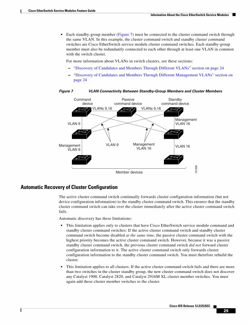
• Each standby-group member (Figure 7) must be connected to the cluster command switch through the same VLAN. In this example, the cluster command switch and standby cluster command switches are Cisco EtherSwitch service module cluster command switches. Each standby-group member must also be redundantly connected to each other through at least one VLAN in common with the switch cluster.
For more information about VLANs in switch clusters, see these sections:
– “Discovery of Candidates and Members Through Different VLANs” section on page 24
– “Discovery of Candidates and Members Through Different Management VLANs” section on page 24
Figure 7 VLAN Connectivity Between Standby-Group Members and Cluster Members
Automatic Recovery of Cluster Configuration
The active cluster command switch continually forwards cluster configuration information (but not device configuration information) to the standby cluster command switch. This ensures that the standby cluster command switch can take over the cluster immediately after the active cluster command switch fails.
Automatic discovery has these limitations:
• This limitation applies only to clusters that have Cisco EtherSwitch service module command and standby cluster command switches: If the active cluster command switch and standby cluster command switch become disabled at the same time, the passive cluster command switch with the highest priority becomes the active cluster command switch. However, because it was a passive standby cluster command switch, the previous cluster command switch did not forward cluster configuration information to it. The active cluster command switch only forwards cluster configuration information to the standby cluster command switch. You must therefore rebuild the cluster.
• This limitation applies to all clusters: If the active cluster command switch fails and there are more than two switches in the cluster standby group, the new cluster command switch does not discover any Catalyst 1900, Catalyst 2820, and Catalyst 2916M XL cluster member switches. You must again add these cluster member switches to the cluster.
1013
26
ManagementVLAN 16
Standbycommand device
VLAN 16VLAN 9
VLAN 9
Commanddevice
Passivecommand device
Member devices
ManagementVLAN 9
VLANs 9,16 VLANs 9,16
ManagementVLAN 16
29Cisco IOS Release 12.2(25)SEC

Cisco EtherSwitch Service Modules Feature GuideInformation About the Cisco EtherSwitch Service Modules
• This limitation applies to all clusters: If the active cluster command switch fails and becomes active again, it does not discover any Catalyst 1900, Catalyst 2820, and Catalyst 2916M XL cluster member switches. You must again add these cluster member switches to the cluster.
When the previously active cluster command switch resumes its active role, it receives a copy of the latest cluster configuration from the active cluster command switch, including members that were added while it was down. The active cluster command switch sends a copy of the cluster configuration to the cluster standby group.
IP Addresses in Clusters
You must assign IP information to a cluster command switch. You can assign more than one IP address to the cluster command switch, and you can access the cluster through any of the command-switch IP addresses. If you configure a cluster standby group, you must use the standby-group virtual IP address to manage the cluster from the active cluster command switch. Using the virtual IP address ensures that you retain connectivity to the cluster if the active cluster command switch fails and that a standby cluster command switch becomes the active cluster command switch.
If the active cluster command switch fails and the standby cluster command switch takes over, you must either use the standby-group virtual IP address or any of the IP addresses available on the new active cluster command switch to access the cluster.
You can assign an IP address to a cluster-capable switch, but it is not necessary. A cluster member switch is managed and communicates with other cluster member switches through the command-switch IP address. If the cluster member switch leaves the cluster and it does not have its own IP address, you then must assign IP information to it to manage it as a standalone switch.
Note Changing the cluster command switch IP address ends your Network Assistant session on the switch. Restart your Network Assistant session by entering the new IP address in the browser Location field (Netscape Communicator) or Address field (Internet Explorer), as described in the release notes.
Hostnames in Clusters
You do not need to assign a hostname to either a cluster command switch or an eligible cluster member. However, a hostname assigned to the cluster command switch can help to identify the switch cluster. The default hostname for the switch is Switch.
If a switch joins a cluster and it does not have a hostname, the cluster command switch appends a unique member number to its own hostname and assigns it sequentially as each switch joins the cluster. The number means the order in which the switch was added to the cluster. For example, a cluster command switch named eng-cluster could name the fifth cluster member eng-cluster-5.
If a switch has a hostname, it retains that name when it joins a cluster. It retains that hostname even after it leaves the cluster.
If a switch received its hostname from the cluster command switch, was removed from a cluster, was then added to a new cluster, and kept the same member number (such as 5), the old hostname (such as eng-cluster-5) is overwritten with the hostname of the cluster command switch in the new cluster (such as mkg-cluster-5). If the switch member number changes in the new cluster (such as 3), the switch retains the previous name (eng-cluster-5).
30Cisco IOS Release 12.2(25)SEC

Cisco EtherSwitch Service Modules Feature GuideInformation About the Cisco EtherSwitch Service Modules
Passwords in Clusters
You do not need to assign passwords to an individual switch if it will be a cluster member. When a switch joins a cluster, it inherits the command-switch password and retains it when it leaves the cluster. If no command-switch password is configured, the cluster member switch inherits a null password. Cluster member switches only inherit the command-switch password.
If you change the member-switch password to be different from the command-switch password and save the change, the switch is not manageable by the cluster command switch until you change the member-switch password to match the command-switch password. Rebooting the member switch does not revert the password back to the command-switch password. We recommend that you do not change the member-switch password after it joins a cluster.
For more information about passwords, see the Catalyst 3750 Switch Software Configuration Guide, Cisco IOS Release 12.2 at http://www.cisco.com/univercd/cc/td/doc/product/lan/cat3750/index.htm.
SNMP Community Strings in Clusters
A cluster member switch inherits the command-switch first read-only (RO) and read-write (RW) community strings with @esN appended to the community strings:
• command-switch-readonly-community-string@esN, where N is the member-switch number.
• command-switch-readwrite-community-string@esN, where N is the member-switch number.
If the cluster command switch has multiple read-only or read-write community strings, only the first read-only and read-write strings are propagated to the cluster member switch.
The switches support an unlimited number of community strings and string lengths. For more information about SNMP and community strings, see the Catalyst 3750 Switch Software Configuration Guide, Cisco IOS Release 12.2 at http://www.cisco.com/univercd/cc/td/doc/product/lan/cat3750/index.htm.
For SNMP considerations specific to the Catalyst 1900 and Catalyst 2820 switches, see the installation and configuration guides specific to those switches.
Switch Clusters and Switch Stacks
A switch cluster can have one or more Cisco EtherSwitch service module switch stacks. Each switch stack can act as the cluster command switch or as a single cluster member. Table 1 describes the basic differences between switch stacks and switch clusters. For more information about switch stacks, see the Catalyst 3750 Switch Software Configuration Guide, Cisco IOS Release 12.2 at http://www.cisco.com/univercd/cc/td/doc/product/lan/cat3750/index.htm.
Table 1 Basic Comparison of Switch Stacks and Switch Clusters
Switch Stack Switch Cluster
A switch stack is made up of Cisco EtherSwitch service modules or Catalyst 3750 switches.
A switch cluster is made up of cluster-capable devices, such as the Cisco EtherSwitch service module or Catalyst 3750 switch.
Stack members are connected through Cisco StackWise ports. Cluster members are connected through LAN ports.
A switch stack requires 1 stack master and supports up to 8 other stack members.
A switch cluster requires 1 cluster command switch and supports up to 15 other cluster member switches.
31Cisco IOS Release 12.2(25)SEC

Cisco EtherSwitch Service Modules Feature GuideInformation About the Cisco EtherSwitch Service Modules
Recall that stack members work together to behave as a unified system (as a single switch stack) in the network and are presented to the network as such by Layer 2 and Layer 3 protocols. Therefore, the switch cluster recognizes switch stacks, not individual stack members, as eligible cluster members. Individual stack members cannot join a switch cluster or participate as separate cluster members. Because a switch cluster must have 1 cluster command switch and can have up to 15 cluster members, a cluster can potentially have up to 16 switch stacks, totalling 144 devices.
Cluster configuration of switch stacks is through the stack master.
Note From Network Assistant or the CLI, you can configure a switch cluster to contain up to 16 switch stacks. However, from Network Assistant, the maximum number of actual devices in a switch cluster is 16, irrespective of the number of devices in switch stack cluster members. For example, if a switch stack contains three stack members, they are counted as three separate devices.
If you used the CLI to configure a switch cluster that contains more than 16 actual devices and then try to display the cluster from Network Assistant. Network Assistant requires you to remove cluster members until the Network Assistant limit of 16 is reached.
These are considerations to keep in mind when you have switch stacks in switch clusters:
• If the cluster command switch is not a Cisco EtherSwitch service module or switch stack and a new stack master is elected in a cluster member switch stack, the switch stack loses its connectivity to the switch cluster if there are no redundant connections between the switch stack and the cluster command switch. You must add the switch stack to the switch cluster.
A switch stack can be a cluster command switch or a cluster member switch.
A switch cluster cannot be a stack master or stack member.
The stack master is the single point of complete management for all stack members in a particular switch stack.
The cluster command switch is the single point of some management for all cluster members in a particular switch cluster.
The backup stack master is automatically determined in case the stack master fails.
The standby cluster command switch must be preassigned in case the cluster command switch fails.
A switch stack supports up to 8 simultaneous stack master failures.
A switch cluster supports only 1 cluster command switch failure at a time.
Stack members (as a switch stack) behave and are presented as a single, unified system in the network.
Cluster members are various, independent switches that are not managed as and do not behave as a unified system.
Management of stack members is integrated through a single configuration file.
Cluster members have separate, individual configuration files.
Stack- and interface-level configurations are stored on each stack member.
Cluster configuration are stored on the cluster command switch and the standby cluster command switch.
New stack members are automatically added to the switch stack.
New cluster members must be manually added to the switch cluster.
Table 1 Basic Comparison of Switch Stacks and Switch Clusters (continued)
Switch Stack Switch Cluster
32Cisco IOS Release 12.2(25)SEC

Cisco EtherSwitch Service Modules Feature GuideHow to Configure the Cisco EtherSwitch Service Module
• If the cluster command switch is a switch stack and new stack masters are simultaneously elected in the cluster command switch stack and in cluster member switch stacks, connectivity between the switch stacks is lost if there are no redundant connections between the switch stack and the cluster command switch. You must add the switch stacks to the cluster, including the cluster command switch stack.
• All stack members should have redundant connectivity to all VLANs in the switch cluster. Otherwise, if a new stack master is elected, stack members connected to any VLANs not configured on the new stack master lose their connectivity to the switch cluster. You must change the VLAN configuration of the stack master or the stack members and add the stack members back to the switch cluster.
• If a cluster member switch stack reloads and a new stack master is elected, the switch stack loses connectivity with the cluster command switch. You must add the switch stack back to the switch cluster.
• If a cluster command switch stack reloads and the original stack master is not re-elected, you must rebuild the entire switch cluster.
For more information about switch stacks, see the Catalyst 3750 Switch Software Configuration Guide, Cisco IOS Release 12.2 at http://www.cisco.com/univercd/cc/td/doc/product/lan/cat3750/index.htm.
TACACS+ and RADIUS in Clusters
Inconsistent authentication configurations in switch clusters cause Network Assistant to continually prompt for a username and password. If TACACS+ is configured on a cluster member, it must be configured on all cluster members. Similarly, if RADIUS is configured on a cluster member, it must be configured on all cluster members. Furthermore, the same switch cluster cannot have some members configured to use TACACS+ and other members configured to use RADIUS.
For more information about TACACS+ and RADIUS, see the Catalyst 3750 Switch Software Configuration Guide, Cisco IOS Release 12.2 at http://www.cisco.com/univercd/cc/td/doc/product/lan/cat3750/index.htm.
Availability of Switch-Specific Features in Switch Clusters
The menu bar on the cluster command switch displays all options available from the switch cluster. Therefore, features specific to a cluster member switch are available from the command-switch menu bar.
How to Configure the Cisco EtherSwitch Service ModuleThis section contains the following procedures:
• Configuring the Cisco EtherSwitch Service Module in the Router, page 36 (required)
• Configuring the Cisco EtherSwitch Service Module Using the Switch Setup Program, page 44 (optional)
• Shutting Down, Resetting, and Reloading the Cisco EtherSwitch Service Module, page 48
Before installing, configuring, or upgrading the switch, see these Catalyst 3750 switch documents:
• For initial configuration information, see the “Using Express Setup” chapter in the getting started guide or to the “Configuring the Switch with the CLI-Based Setup Program” appendix in the hardware installation guide.
33Cisco IOS Release 12.2(25)SEC

Cisco EtherSwitch Service Modules Feature GuideHow to Configure the Cisco EtherSwitch Service Module
• For device manager requirements, see the “System Requirements” section in the release notes (not orderable but available on Cisco.com).
• For Network Assistant requirements, see Getting Started with Cisco Network Assistant (not orderable but available on Cisco.com).
Accessing the CLI Through a Console Connection or Through TelnetBefore you can access the Cisco EtherSwitch service module CLI, you must connect to the host router through the router console or through Telnet. Once you are connected to the router, you must configure an IP address on the Gigabit Ethernet interface connected to the Cisco EtherSwitch service module. Open a session to the Cisco EtherSwitch service module using the service-module ge x/0 session command in privileged EXEC mode on the router.
If your Cisco EtherSwitch service module is already configured, you can directly configure the service module through its CLI.
You can use one of these methods to establish a connection to the Cisco EtherSwitch service module:
• Connect to the router console using Telnet or SSH and open a session to the switch using the service-module gig x/0 session command in privileged EXEC mode on the router.
Note When connecting to the router through the console using Telnet or SSH from a client station, you must have IP connectivity from the station to the switch.
• Use any Telnet TCP/IP or encrypted SSH package from a remote management station. The internal interface must have network connectivity with the Telnet or SSH client, and the internal interface must have an enable secret password configured. After you connect through the CLI, a Telnet session, or an SSH session, the user EXEC prompt appears on the management station.
The Cisco EtherSwitch service module or switch supports up to 5 simultaneous secure SSH sessions and up to 16 simultaneous Telnet sessions. Changes made by one Telnet user are reflected in all other Telnet sessions. For information about configuring the Cisco EtherSwitch service module or switch for Telnet access, see the Catalyst 3750 Switch Software Configuration Guide, Cisco IOS Release 12.2 at the following URL:
http://www.cisco.com/univercd/cc/td/doc/product/lan/cat3750/index.htm
Understanding Interface Types on the Cisco EtherSwitch Service ModulesThis section describes the different types of interfaces supported by the Cisco EtherSwitch service module with references to chapters that contain more detailed information about configuring these interface types.
The Cisco EtherSwitch service module supports the following interface types:
• Fast Ethernet interfaces
• External Gigabit Ethernet interfaces
• VLAN switched virtual interface (SVI)
• Internal Gigabit Ethernet interfaces; the last one is the one internally connected to the host router
34Cisco IOS Release 12.2(25)SEC

Cisco EtherSwitch Service Modules Feature GuideHow to Configure the Cisco EtherSwitch Service Module
The interface numbering format on the Cisco EtherSwitch service module is stack-member-number/0/switch-port. For more detailed information about interface types, see the Catalyst 3750 Switch Software Configuration Guide, Cisco IOS Release 12.2 at the following URL:
http://www.cisco.com/univercd/cc/td/doc/product/lan/cat3750/index.htm
Using Interface Configuration ModeYou can configure the individual Cisco EtherSwitch service module physical interfaces (ports) through the interface configuration mode on the CLI. The port numbering scheme that you use in interface configuration mode is interface type stack member number/0/port number.
Note For Cisco EtherSwitch service modules or switches that do not have StackWise interfaces, the stack member number is 1 by default but changeable through Cisco IOS software or bootloader.
• Type—Fast Ethernet (fastethernet or fa) for 10/100-Mbps Ethernet or Gigabit Ethernet (gigabitethernet or gi) for 10/100/1000-Mbps Ethernet ports.
• Stack member number—The number used to identify the Cisco EtherSwitch service module or switch within the stack. The Cisco EtherSwitch service module or switch number ranges from 1 to 9 and is assigned the first time the service module or switch initializes. The default Cisco EtherSwitch service module or switch number, before it is integrated into a switch stack, is 1; when a service module or switch has been assigned a stack member number, it keeps that number until another is assigned to it.
You can use the Cisco EtherSwitch service module or switch port LEDs in stack mode to identify the stack member number of a service module or switch.
• Module number—The module slot number on the Cisco EtherSwitch service module or switch (always 0 on the service module or switch).
• Port number—The interface number on the Cisco EtherSwitch service module or switch. The port numbers always begin at 1, starting at the right when facing the front of the Cisco EtherSwitch service module, for example, fastethernet 1/0/1, fastethernet 1/0/2, gigabitethernet 1/0/1, gigabitethernet 1/0/2 with 1/0/1 on the top, 1/0/2 on the bottom, 1/0/3 on the top, 1/0/4 on the bottom and so on.
You can identify physical interfaces by physically checking the interface location on the Cisco EtherSwitch service module. You can also use the Cisco IOS show privileged EXEC commands to display information about a specific interface or all the interfaces on the Cisco EtherSwitch service module.
These are examples of specifying interfaces:
• To specify Gigabit Ethernet port 4 on a standalone Cisco EtherSwitch service module, enter this command in global configuration mode:
Enhanced EtherSwitch (config)# interface gigabitethernet1/0/4
• To specify Fast Ethernet port 4 on stack member 3, enter this command in global configuration mode:
Enhanced EtherSwitch (config)# interface fastethernet3/0/4
For more detailed information about configuring interfaces, see the Catalyst 3750 Switch Software Configuration Guide, Cisco IOS Release 12.2 at the following URL:
http://www.cisco.com/univercd/cc/td/doc/product/lan/cat3750/index.htm
35Cisco IOS Release 12.2(25)SEC
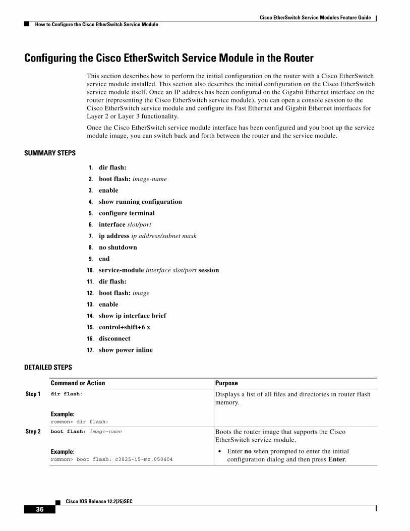
Cisco EtherSwitch Service Modules Feature GuideHow to Configure the Cisco EtherSwitch Service Module
Configuring the Cisco EtherSwitch Service Module in the RouterThis section describes how to perform the initial configuration on the router with a Cisco EtherSwitch service module installed. This section also describes the initial configuration on the Cisco EtherSwitch service module itself. Once an IP address has been configured on the Gigabit Ethernet interface on the router (representing the Cisco EtherSwitch service module), you can open a console session to the Cisco EtherSwitch service module and configure its Fast Ethernet and Gigabit Ethernet interfaces for Layer 2 or Layer 3 functionality.
Once the Cisco EtherSwitch service module interface has been configured and you boot up the service module image, you can switch back and forth between the router and the service module.
SUMMARY STEPS
1. dir flash:
2. boot flash: image-name
3. enable
4. show running configuration
5. configure terminal
6. interface slot/port
7. ip address ip address/subnet mask
8. no shutdown
9. end
10. service-module interface slot/port session
11. dir flash:
12. boot flash: image
13. enable
14. show ip interface brief
15. control+shift+6 x
16. disconnect
17. show power inline
DETAILED STEPS
Command or Action Purpose
Step 1 dir flash:
Example:rommon> dir flash:
Displays a list of all files and directories in router flash memory.
Step 2 boot flash: image-name
Example:rommon> boot flash: c3825-i5-mz.050404
Boots the router image that supports the Cisco EtherSwitch service module.
• Enter no when prompted to enter the initial configuration dialog and then press Enter.
36Cisco IOS Release 12.2(25)SEC
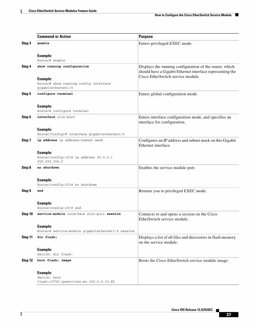
Cisco EtherSwitch Service Modules Feature GuideHow to Configure the Cisco EtherSwitch Service Module
Step 3 enable
Example:Router# enable
Enters privileged EXEC mode.
Step 4 show running configuration
Example:Router# show running config interface gigabitethernet1/0
Displays the running configuration of the router, which should have a Gigabit Ethernet interface representing the Cisco EtherSwitch service module.
Step 5 configure terminal
Example:Router# configure terminal
Enters global configuration mode.
Step 6 interface slot/port
Example:Router(config)# interface gigabitethernet1/0
Enters interface configuration mode, and specifies an interface for configuration.
Step 7 ip address ip address/subnet mask
Example:Router(config-if)# ip address 20.0.0.1 255.255.255.0
Configures an IP address and subnet mask on this Gigabit Ethernet interface.
Step 8 no shutdown
Example:Router(config-if)# no shutdown
Enables the service module port.
Step 9 end
Example:Router(config-if)# end
Returns you to privileged EXEC mode.
Step 10 service-module interface slot/port session
Example:Router# service-module gigabitethernet1/0 session
Connects to and opens a session on the Cisco EtherSwitch service module.
Step 11 dir flash:
Example:Switch: dir flash:
Displays a list of all files and directories in flash memory on the service module.
Step 12 boot flash: image
Example:Switch: boot flash:c3750-ipservices-mz.122-0.0.13.EZ
Boots the Cisco EtherSwitch service module image.
Command or Action Purpose
37Cisco IOS Release 12.2(25)SEC

Cisco EtherSwitch Service Modules Feature GuideHow to Configure the Cisco EtherSwitch Service Module
Step 13 enable
Example:Switch> enable
Enters privileged EXEC mode on the Cisco EtherSwitch service module.
Step 14 show ip interface brief
Example:Switch# show ip interface brief
Displays brief version of the Cisco EtherSwitch service module configuration information.
Step 15 control+shift+6 x
Example:Switch# control+shift+6 x
Returns you to the router console while keeping the console session to the switch intact.
Step 16 disconnect
Example:Router# disconnect
Terminates the console session to the Cisco EtherSwitch service module.
Step 17 show power inline
Example:Router# show power inline
Displays the PoE statistics maintained on the Cisco EtherSwitch service module.
Note PoE statistics are updated dynamically.
Output of the show service-module status command must be in steady state for inline power to function.
Command or Action Purpose
38Cisco IOS Release 12.2(25)SEC

Cisco EtherSwitch Service Modules Feature GuideHow to Configure the Cisco EtherSwitch Service Module
Examples
This section provides the following examples:
• Sample Output for the dir flash: Command on the Router, page 39
• Sample Output for the boot flash: Command on the Router, page 39
• Sample Output for the show running config Command on the Router, page 40
• Sample Output for Configuring the Cisco EtherSwitch Service Module Interface on the Router, page 40
• Sample Output for the service-module Command on the Cisco EtherSwitch Service Module, page 40
• Sample Output for the dir flash: Command on the Cisco EtherSwitch Service Module, page 40
• Sample Output for the boot flash: Command on the Cisco EtherSwitch Service Module, page 40
• Sample Output for the show ip interface brief Command on the Cisco EtherSwitch Service Module, page 41
• Sample Output for Pressing <Ctrl+Shift+6> Followed by x, page 41
• Sample Output for the show power inline Command on the Cisco EtherSwitch service module, page 41
Sample Output for the dir flash: Command on the Router
The following example shows what appears when you enter the dir flash: command:
Router> dir flash:Directory of flash:/
program load complete, entry point: 0x8000f000, size: 0xc0c0
Initializing ATA monitor library.......Directory of flash:
2 29823132 -rw- c2800-adventerprisek9-mz
Sample Output for the boot flash: Command on the Router
The following example shows what appears when you enter the boot flash: command:
Router> boot flash:c2800-adventerprisek9-mz
program load complete, entry point: 0x8000f000, size: 0xc0c0
Initializing ATA monitor library.......
program load complete, entry point: 0x8000f000, size: 0x1c70efcSelf decompressing the image : #################################################################################################################################### [OK]...
After the router completes the boot process, you will be prompted to enter the initial configuration dialog as in the following example. Enter no.
Would you like to enter the initial configuration dialog? [yes/no]: no
Press RETURN to get started!
Press Enter. You will be at the router prompt.
39Cisco IOS Release 12.2(25)SEC
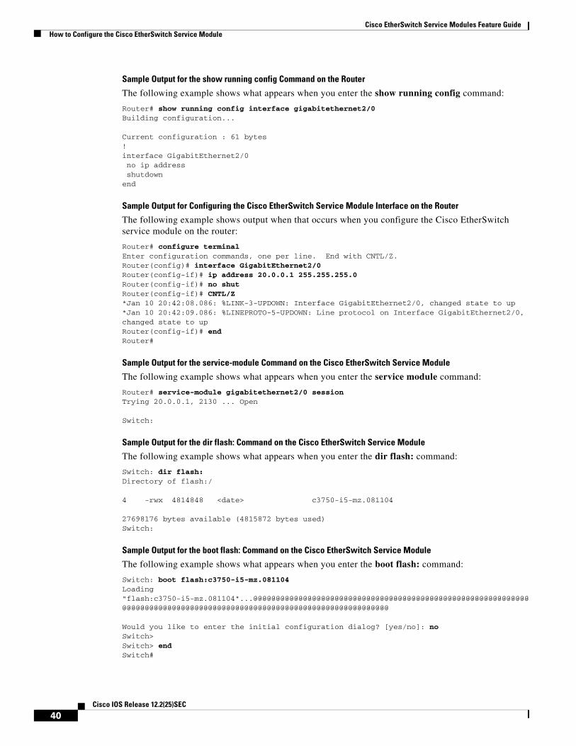
Cisco EtherSwitch Service Modules Feature GuideHow to Configure the Cisco EtherSwitch Service Module
Sample Output for the show running config Command on the Router
The following example shows what appears when you enter the show running config command:
Router# show running config interface gigabitethernet2/0Building configuration...
Current configuration : 61 bytes!interface GigabitEthernet2/0 no ip address shutdownend
Sample Output for Configuring the Cisco EtherSwitch Service Module Interface on the Router
The following example shows output when that occurs when you configure the Cisco EtherSwitch service module on the router:
Router# configure terminalEnter configuration commands, one per line. End with CNTL/Z.Router(config)# interface GigabitEthernet2/0Router(config-if)# ip address 20.0.0.1 255.255.255.0Router(config-if)# no shutRouter(config-if)# CNTL/Z*Jan 10 20:42:08.086: %LINK-3-UPDOWN: Interface GigabitEthernet2/0, changed state to up*Jan 10 20:42:09.086: %LINEPROTO-5-UPDOWN: Line protocol on Interface GigabitEthernet2/0, changed state to up Router(config-if)# endRouter#
Sample Output for the service-module Command on the Cisco EtherSwitch Service Module
The following example shows what appears when you enter the service module command:
Router# service-module gigabitethernet2/0 session Trying 20.0.0.1, 2130 ... Open
Switch:
Sample Output for the dir flash: Command on the Cisco EtherSwitch Service Module
The following example shows what appears when you enter the dir flash: command:
Switch: dir flash:Directory of flash:/
4 -rwx 4814848 <date> c3750-i5-mz.081104
27698176 bytes available (4815872 bytes used)Switch:
Sample Output for the boot flash: Command on the Cisco EtherSwitch Service Module
The following example shows what appears when you enter the boot flash: command:
Switch: boot flash:c3750-i5-mz.081104Loading "flash:c3750-i5-mz.081104"...@@@@@@@@@@@@@@@@@@@@@@@@@@@@@@@@@@@@@@@@@@@@@@@@@@@@@@@@@@@@@@@@@@@@@@@@@@@@@@@@@@@@@@@@@@@@@@@@@@@@@@@@@@@@@@@@@@@@@@@@
Would you like to enter the initial configuration dialog? [yes/no]: noSwitch>Switch> endSwitch#
40Cisco IOS Release 12.2(25)SEC

Cisco EtherSwitch Service Modules Feature GuideHow to Configure the Cisco EtherSwitch Service Module
Sample Output for the show ip interface brief Command on the Cisco EtherSwitch Service Module
The following example shows what appears when you enter the show ip interface brief command:
Switch# show ip interface briefInterface IP-Address OK? Method Status ProtocolVlan1 unassigned YES unset administratively down down FastEthernet1/0/1 unassigned YES unset down down FastEthernet1/0/2 unassigned YES unset down down FastEthernet1/0/3 unassigned YES unset down down FastEthernet1/0/4 unassigned YES unset down down FastEthernet1/0/5 unassigned YES unset down down
Sample Output for Pressing <Ctrl+Shift+6> Followed by x
The following example shows what appears when you press <Ctrl+Shift+6> and then press x:
Switch# ctrl+shift+6, xRouter#
Sample Output for the show power inline Command on the Router
The following example shows what appears when you enter the show inline power command on the router:
Router# show power inlinePowerSupply SlotNum. Maximum Allocated Status----------- -------- ------- --------- ------INT-PS 0 360.000 0.000 PS1 GOOD PS2 ABSENT Interface Config Phone Powered PowerAllocated--------- ------ ----- ------- -------------- Gi2/0 auto Unknown Off 0.000 Watts Gi4/0 auto Unknown Off 0.000 Watts Router#
Sample Output for the show power inline Command on the Cisco EtherSwitch service module
The following example shows what appears when you enter the show inline power command on the switch:
Switch# show power inline
Module Available Used Remaining (Watts) (Watts) (Watts) ------ --------- -------- ---------1 360.0 0.0 360.0
Interface Admin Oper Power Device Class (Watts) ---------- ----- ---------- ------- ------------------- ----------Fa1/0/1 auto off 0.0 n/a n/a Fa1/0/2 auto off 0.0 n/a n/a Fa1/0/3 auto off 0.0 n/a n/a Fa1/0/4 auto off 0.0 n/a n/a Fa1/0/5 auto off 0.0 n/a n/a Fa1/0/6 auto off 0.0 n/a n/a Fa1/0/7 auto off 0.0 n/a n/a ----------------------------------------------------------
41Cisco IOS Release 12.2(25)SEC
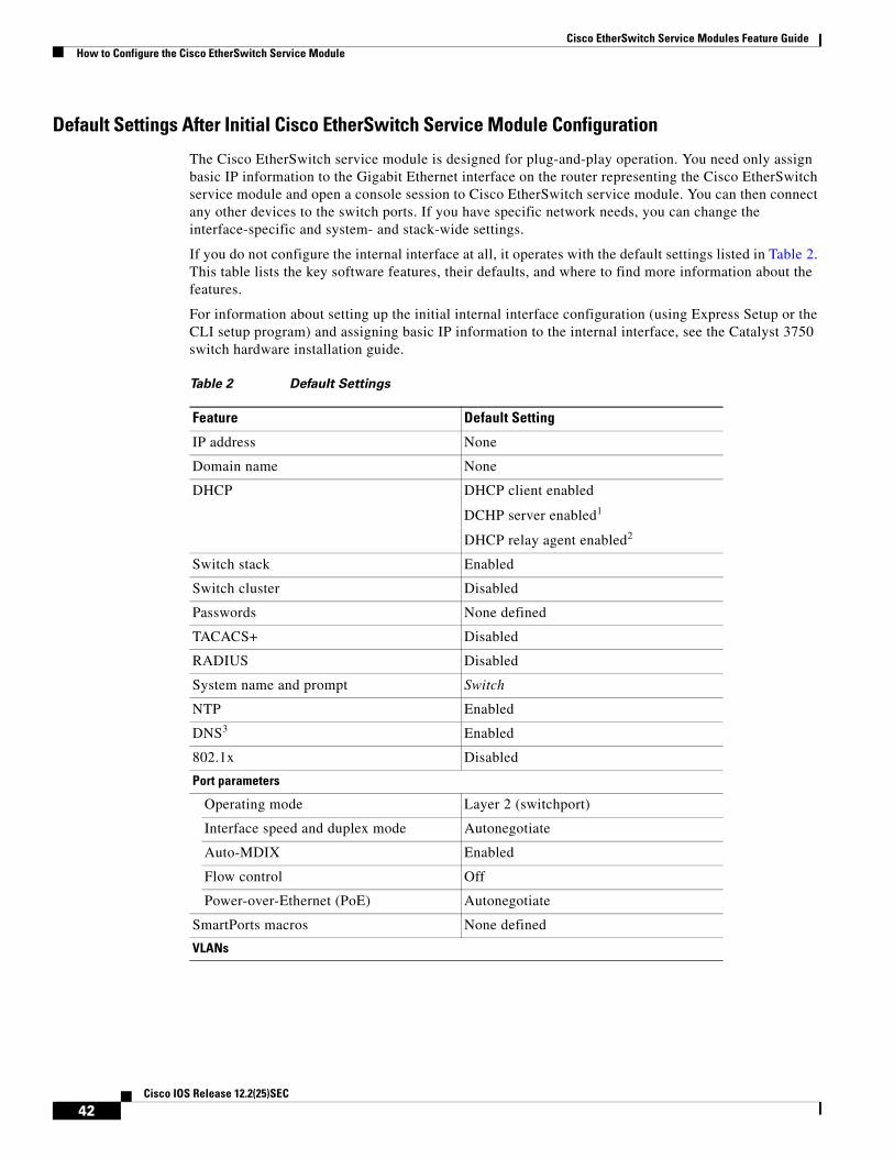
Cisco EtherSwitch Service Modules Feature GuideHow to Configure the Cisco EtherSwitch Service Module
Default Settings After Initial Cisco EtherSwitch Service Module Configuration
The Cisco EtherSwitch service module is designed for plug-and-play operation. You need only assign basic IP information to the Gigabit Ethernet interface on the router representing the Cisco EtherSwitch service module and open a console session to Cisco EtherSwitch service module. You can then connect any other devices to the switch ports. If you have specific network needs, you can change the interface-specific and system- and stack-wide settings.
If you do not configure the internal interface at all, it operates with the default settings listed in Table 2. This table lists the key software features, their defaults, and where to find more information about the features.
For information about setting up the initial internal interface configuration (using Express Setup or the CLI setup program) and assigning basic IP information to the internal interface, see the Catalyst 3750 switch hardware installation guide.
Table 2 Default Settings
Feature Default Setting
IP address None
Domain name None
DHCP DHCP client enabled
DCHP server enabled1
DHCP relay agent enabled2
Switch stack Enabled
Switch cluster Disabled
Passwords None defined
TACACS+ Disabled
RADIUS Disabled
System name and prompt Switch
NTP Enabled
DNS3 Enabled
802.1x Disabled
Port parameters
Operating mode Layer 2 (switchport)
Interface speed and duplex mode Autonegotiate
Auto-MDIX Enabled
Flow control Off
Power-over-Ethernet (PoE) Autonegotiate
SmartPorts macros None defined
VLANs
42Cisco IOS Release 12.2(25)SEC
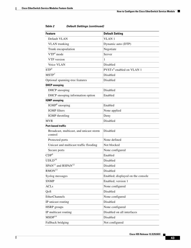
Cisco EtherSwitch Service Modules Feature GuideHow to Configure the Cisco EtherSwitch Service Module
Default VLAN VLAN 1
VLAN trunking Dynamic auto (DTP)
Trunk encapsulation Negotiate
VTP4 mode Server
VTP version 1
Voice VLAN Disabled
STP5 PVST+6 enabled on VLAN 1
MSTP7 Disabled
Optional spanning-tree features Disabled
DHCP snooping
DHCP snooping Disabled
DHCP snooping information option Enabled
IGMP snooping
IGMP8 snooping Enabled
IGMP filters None applied
IGMP throttling Deny
MVR Disabled
Port-based traffic
Broadcast, multicast, and unicast storm control
Disabled
Protected ports None defined
Unicast and multicast traffic flooding Not blocked
Secure ports None configured
CDP9 Enabled
UDLD10 Disabled
SPAN11 and RSPAN12 Disabled
RMON13 Disabled
Syslog messages Enabled; displayed on the console
SNMP Enabled; version 1
ACLs None configured
QoS Disabled
EtherChannels None configured
IP unicast routing Disabled
HSRP groups None configured
IP multicast routing Disabled on all interfaces
MSDP14 Disabled
Fallback bridging Not configured
Table 2 Default Settings (continued)
Feature Default Setting
43Cisco IOS Release 12.2(25)SEC
Cisco EtherSwitch Service Modules Feature GuideHow to Configure the Cisco EtherSwitch Service Module
Configuring the Cisco EtherSwitch Service Module Using the Switch Setup Program
This section describes how to configure the Cisco EtherSwitch service module, using the setup program on the service module to create an initial configuration. The setup program enables the Cisco EtherSwitch service module to run on its standard default settings.
The setup program runs automatically after the Cisco EtherSwitch service module is powered up, but does not have an existing configuration. You must assign an IP address and other configuration information necessary for the Cisco EtherSwitch service module to communicate to other devices on the network. This information is also required if you plan to use the Cisco Network Assistant (hereafter referred to as Network Assistant) application software.
After you complete the setup program, the Cisco EtherSwitch service module can run the default configuration that you created. If you want to change this configuration or want to perform other management tasks, use one of these tools:
• Command-line interface (CLI)
• Cisco Network Assistant application program from your browser
To use the CLI, enter commands at the switch> prompt through the console session to the Cisco EtherSwitch service module. For configuration information, see the Catalyst 3750 Switch Software Configuration Guide, Cisco IOS Release 12.2 at the following URL:
http://www.cisco.com/univercd/cc/td/doc/product/lan/cat3750/index.htm
To use Network Assistant, see the Cisco Network Assistant documentation at the following URL:
http://www.cisco.com/univercd/cc/td/doc/product/rtrmgmt/cna/v2_0/index.htm
Prerequisites
Obtain the following items from your network administrator before you start the setup program:
• IP address for the Gigabit Ethernet interface on the router
• Subnet mask (IP netmask)
• Default gateway of the router
• Enable secret password
1. Only if the device acting as a DCHP server is configured and enabled.
2. Only if the device acting as a DHCP relay agent is configured and enabled.
3. DNS = Domain Name System
4. VTP = VLAN Trunking Protocol
5. STP = Spanning Tree Protocol
6. PVST+ = Per VLAN Spanning Tree Enhanced
7. MSTP = Multi-service Transport Platforms
8. IGMP = Internet Group Management Protocol
9. CDP = Cisco Discovery Protocol
10. UDLD = Unidirectional Link Detection Protocol
11. SPAN = Local Switch Port Analyzer
12. RSPAN = Remote Switch Port Analyzer
13. RMON = Remote Monitoring
14. MSDP = Multicast Source Discovery Protocol
44Cisco IOS Release 12.2(25)SEC

Cisco EtherSwitch Service Modules Feature GuideHow to Configure the Cisco EtherSwitch Service Module
• Enable password
• Telnet password
Note If your Cisco EtherSwitch service modules are stacked and there are multiple console connections to individual Cisco EtherSwitch service modules in the stack, the initial setup dialog appears on the first console where the user presses Enter.
SUMMARY STEPS
1. When prompted to enter the initial configuration dialog, enter yes.
2. Enter a hostname for the Cisco EtherSwitch service module, and press Return.
3. Enter an enable secret password, and press Return.
4. Enter an enable password, and press Return.
5. Enter a virtual terminal (Telnet) password, and press Return.
6. (Optional) Enter yes to configure SNMP or no to configure SNMP later through the CLI or Network Assistant, and then press Return.
7. Enter the interface name and press Return.
8. Enter yes and press Return.
9. Enter the Cisco EtherSwitch service module IP address and subnet mask and press Return .
10. Enter no and press Return.
11. Enter 2 and press Return.
DETAILED STEPS
Command or Action Purpose
Step 1 When prompted to enter the initial configuration dialog, enter yes.
Initiates initial configuration dialog and basic management setup.
Step 2 Enter a hostname for the Cisco EtherSwitch service module, and press Return.
Sets the hostname for the Cisco EtherSwitch service module.
• On a cluster command Cisco EtherSwitch service module, the hostname is limited to 28 characters; on a cluster member Cisco EtherSwitch service module, the limit is 31 characters.
• Do not use -n, where n is a number, as the last character in a hostname for any Cisco EtherSwitch service module.
For additional information about switch clusters, see the “Clustering Concepts” section on page 20.
Step 3 Enter an enable secret password, and press Return. Sets the secret password to access privileged EXEC mode.
• The password can be from 1 to 25 alphanumeric characters, can start with a number, is case sensitive, allows spaces, but ignores leading spaces.
• The secret password is encrypted and the enable password is in plain text.
45Cisco IOS Release 12.2(25)SEC
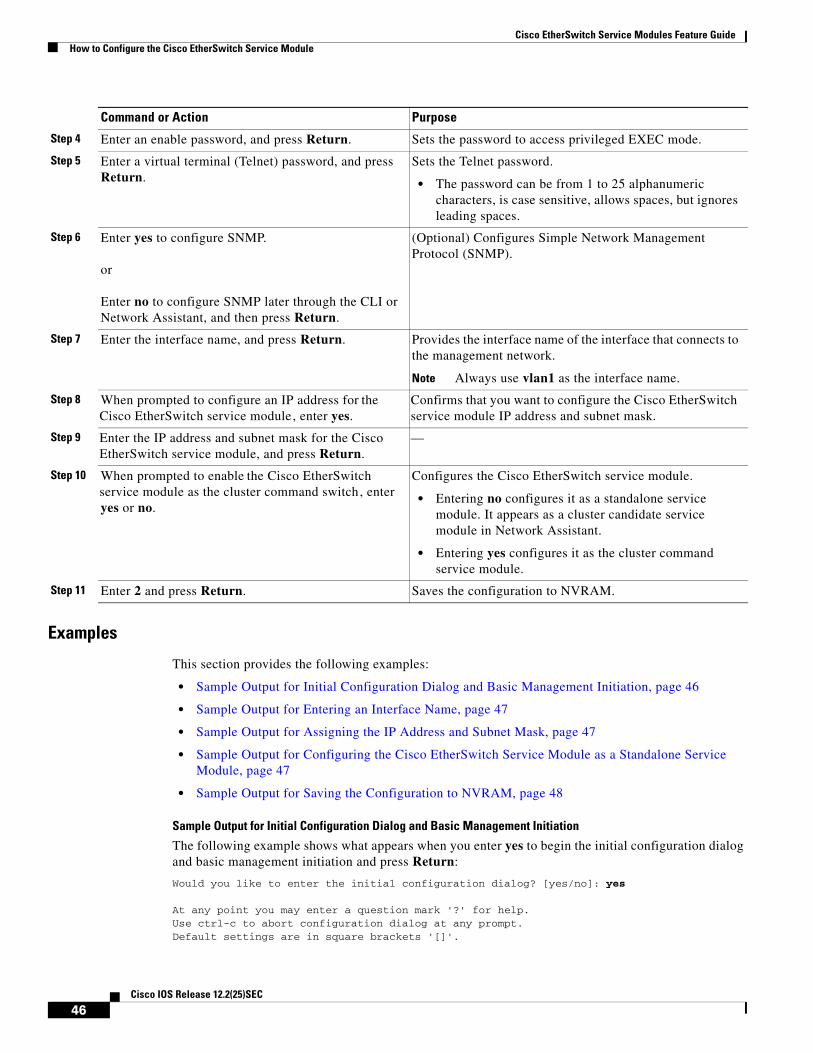
Cisco EtherSwitch Service Modules Feature GuideHow to Configure the Cisco EtherSwitch Service Module
Examples
This section provides the following examples:
• Sample Output for Initial Configuration Dialog and Basic Management Initiation, page 46
• Sample Output for Entering an Interface Name, page 47
• Sample Output for Assigning the IP Address and Subnet Mask, page 47
• Sample Output for Configuring the Cisco EtherSwitch Service Module as a Standalone Service Module, page 47
• Sample Output for Saving the Configuration to NVRAM, page 48
Sample Output for Initial Configuration Dialog and Basic Management Initiation
The following example shows what appears when you enter yes to begin the initial configuration dialog and basic management initiation and press Return:
Would you like to enter the initial configuration dialog? [yes/no]: yes
At any point you may enter a question mark '?' for help.Use ctrl-c to abort configuration dialog at any prompt.Default settings are in square brackets '[]'.
Step 4 Enter an enable password, and press Return. Sets the password to access privileged EXEC mode.
Step 5 Enter a virtual terminal (Telnet) password, and press Return.
Sets the Telnet password.
• The password can be from 1 to 25 alphanumeric characters, is case sensitive, allows spaces, but ignores leading spaces.
Step 6 Enter yes to configure SNMP.
or
Enter no to configure SNMP later through the CLI or Network Assistant, and then press Return.
(Optional) Configures Simple Network Management Protocol (SNMP).
Step 7 Enter the interface name, and press Return. Provides the interface name of the interface that connects to the management network.
Note Always use vlan1 as the interface name.
Step 8 When prompted to configure an IP address for the Cisco EtherSwitch service module , enter yes.
Confirms that you want to configure the Cisco EtherSwitch service module IP address and subnet mask.
Step 9 Enter the IP address and subnet mask for the Cisco EtherSwitch service module, and press Return.
—
Step 10 When prompted to enable the Cisco EtherSwitch service module as the cluster command switch, enter yes or no.
Configures the Cisco EtherSwitch service module.
• Entering no configures it as a standalone service module. It appears as a cluster candidate service module in Network Assistant.
• Entering yes configures it as the cluster command service module.
Step 11 Enter 2 and press Return. Saves the configuration to NVRAM.
Command or Action Purpose
46Cisco IOS Release 12.2(25)SEC
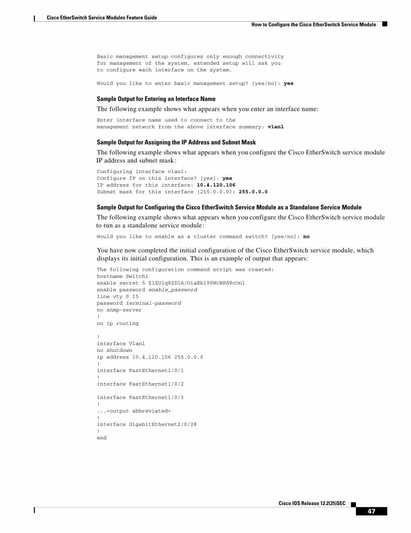
Cisco EtherSwitch Service Modules Feature GuideHow to Configure the Cisco EtherSwitch Service Module
Basic management setup configures only enough connectivityfor management of the system, extended setup will ask youto configure each interface on the system.
Would you like to enter basic management setup? [yes/no]: yes
Sample Output for Entering an Interface Name
The following example shows what appears when you enter an interface name:
Enter interface name used to connect to themanagement network from the above interface summary: vlan1
Sample Output for Assigning the IP Address and Subnet Mask
The following example shows what appears when you configure the Cisco EtherSwitch service module IP address and subnet mask:
Configuring interface vlan1:Configure IP on this interface? [yes]: yes IP address for this interface: 10.4.120.106Subnet mask for this interface [255.0.0.0]: 255.0.0.0
Sample Output for Configuring the Cisco EtherSwitch Service Module as a Standalone Service Module
The following example shows what appears when you configure the Cisco EtherSwitch service module to run as a standalone service module:
Would you like to enable as a cluster command switch? [yes/no]: no
You have now completed the initial configuration of the Cisco EtherSwitch service module, which displays its initial configuration. This is an example of output that appears:
The following configuration command script was created:hostname Switch1enable secret 5 $1$Ulq8$DlA/OiaEbl90WcBPd9cOn1enable password enable_passwordline vty 0 15password terminal-passwordno snmp-server!no ip routing
!interface Vlan1no shutdownip address 10.4.120.106 255.0.0.0!interface FastEthernet1/0/1!interface FastEthernet1/0/2
interface FastEthernet1/0/3!...<output abbreviated>!interface GigabitEthernet2/0/28!end
47Cisco IOS Release 12.2(25)SEC
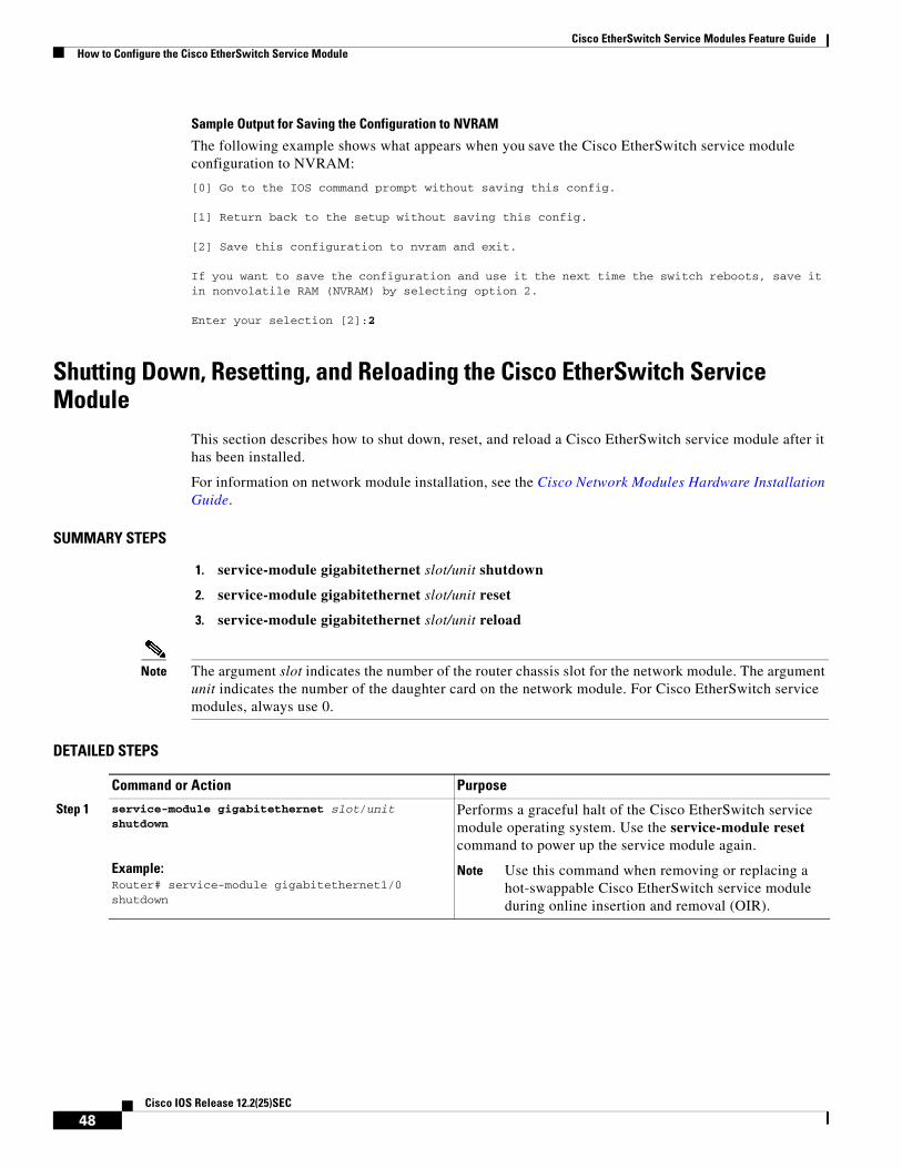
Cisco EtherSwitch Service Modules Feature GuideHow to Configure the Cisco EtherSwitch Service Module
Sample Output for Saving the Configuration to NVRAM
The following example shows what appears when you save the Cisco EtherSwitch service module configuration to NVRAM:
[0] Go to the IOS command prompt without saving this config.
[1] Return back to the setup without saving this config.
[2] Save this configuration to nvram and exit.
If you want to save the configuration and use it the next time the switch reboots, save it in nonvolatile RAM (NVRAM) by selecting option 2.
Enter your selection [2]:2
Shutting Down, Resetting, and Reloading the Cisco EtherSwitch Service Module
This section describes how to shut down, reset, and reload a Cisco EtherSwitch service module after it has been installed.
For information on network module installation, see the Cisco Network Modules Hardware Installation Guide.
SUMMARY STEPS
1. service-module gigabitethernet slot/unit shutdown
2. service-module gigabitethernet slot/unit reset
3. service-module gigabitethernet slot/unit reload
Note The argument slot indicates the number of the router chassis slot for the network module. The argument unit indicates the number of the daughter card on the network module. For Cisco EtherSwitch service modules, always use 0.
DETAILED STEPS
Command or Action Purpose
Step 1 service-module gigabitethernet slot/unit shutdown
Example:Router# service-module gigabitethernet1/0 shutdown
Performs a graceful halt of the Cisco EtherSwitch service module operating system. Use the service-module reset command to power up the service module again.
Note Use this command when removing or replacing a hot-swappable Cisco EtherSwitch service module during online insertion and removal (OIR).
48Cisco IOS Release 12.2(25)SEC
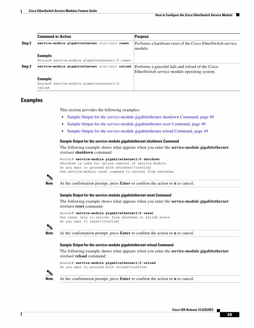
Cisco EtherSwitch Service Modules Feature GuideHow to Configure the Cisco EtherSwitch Service Module
Examples
This section provides the following examples:
• Sample Output for the service-module gigabitethernet shutdown Command, page 49
• Sample Output for the service-module gigabitethernet reset Command, page 49
• Sample Output for the service-module gigabitethernet reload Command, page 49
Sample Output for the service-module gigabitethernet shutdown Command
The following example shows what appears when you enter the service-module gigabitethernet slot/unit shutdown command:
Router# service-module gigabitethernet1/0 shutdownShutdown is used for Online removal of Service Module.Do you want to proceed with shutdown?[confirm]Use service-module reset command to recover from shutdown.
Note At the confirmation prompt, press Enter to confirm the action or n to cancel.
Sample Output for the service-module gigabitethernet reset Command
The following example shows what appears when you enter the service-module gigabitethernet slot/unit reset command:
Router# service-module gigabitethernet1/0 resetUse reset only to recover from shutdown or failed stateDo you want to reset?[confirm]
Note At the confirmation prompt, press Enter to confirm the action or n to cancel.
Sample Output for the service-module gigabitethernet reload Command
The following example shows what appears when you enter the service-module gigabitethernet slot/unit reload command:
Router# service-module gigabitethernet1/0 reloadDo you want to proceed with reload?[confirm]
Note At the confirmation prompt, press Enter to confirm the action or n to cancel.
Step 2 service-module gigabitethernet slot/unit reset
Example:Router# service-module gigabitethernet1/0 reset
Performs a hardware reset of the Cisco EtherSwitch service module.
Step 3 service-module gigabitethernet slot/unit reload
Example:Router# service-module gigabitethernet1/0 reload
Performs a graceful halt and reload of the Cisco EtherSwitch service module operating system.
Command or Action Purpose
49Cisco IOS Release 12.2(25)SEC

Cisco EtherSwitch Service Modules Feature GuideHow to Configure the Cisco EtherSwitch Service Module in a Switch Stack
How to Configure the Cisco EtherSwitch Service Module in a Switch Stack
This section describes how to configure the Cisco EtherSwitch service module in a switch stack. A switch stack is a set of Cisco EtherSwitch service modules connected through their Cisco StackWise ports. One of the Cisco EtherSwitch service modules controls the operation of the stack and is called the stack master. The stack master and the other service modules in the stack are stack members. The stack members use Cisco StackWise technology to behave and work together as a unified system. Layer 2 and Layer 3 protocols present the entire switch stack as a single entity to the network.
The stack master is the single point of stack-wide management. From the stack master, you configure these items:
• System-level (global) features that apply to all stack members
• Interface-level features for each stack member
A switch stack is identified in the network by its bridge ID and, if the switch stack is operating as a Layer 3 device, by its router MAC address. The bridge ID and router MAC address are determined by the MAC address of the stack master. Every stack member is uniquely identified by its own stack member number.
Note You manage the switch stack through a single IP address. The IP address is a system-level setting and is not specific to the stack master or to any other stack member. You can manage the stack through the same IP address even if you remove the stack master or any other stack member from the stack.
This section contains the following procedures:
• Default Switch Stack Configuration, page 51
• Assigning a Stack Member Number, page 52
• Setting the Stack Member Priority Value, page 54
• Verifying Information About the Switch Stack, page 55
50Cisco IOS Release 12.2(25)SEC
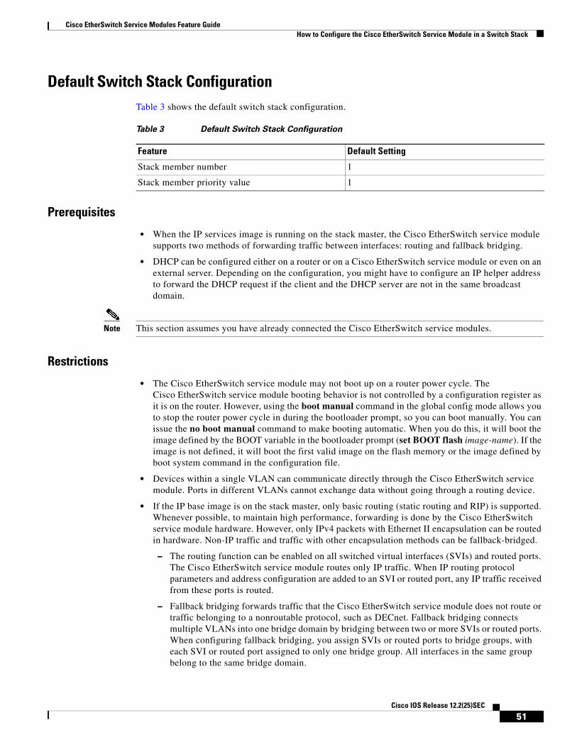
Cisco EtherSwitch Service Modules Feature GuideHow to Configure the Cisco EtherSwitch Service Module in a Switch Stack
Default Switch Stack ConfigurationTable 3 shows the default switch stack configuration.
Prerequisites
• When the IP services image is running on the stack master, the Cisco EtherSwitch service module supports two methods of forwarding traffic between interfaces: routing and fallback bridging.
• DHCP can be configured either on a router or on a Cisco EtherSwitch service module or even on an external server. Depending on the configuration, you might have to configure an IP helper address to forward the DHCP request if the client and the DHCP server are not in the same broadcast domain.
Note This section assumes you have already connected the Cisco EtherSwitch service modules.
Restrictions
• The Cisco EtherSwitch service module may not boot up on a router power cycle. The Cisco EtherSwitch service module booting behavior is not controlled by a configuration register as it is on the router. However, using the boot manual command in the global config mode allows you to stop the router power cycle in during the bootloader prompt, so you can boot manually. You can issue the no boot manual command to make booting automatic. When you do this, it will boot the image defined by the BOOT variable in the bootloader prompt (set BOOT flash image-name). If the image is not defined, it will boot the first valid image on the flash memory or the image defined by boot system command in the configuration file.
• Devices within a single VLAN can communicate directly through the Cisco EtherSwitch service module. Ports in different VLANs cannot exchange data without going through a routing device.
• If the IP base image is on the stack master, only basic routing (static routing and RIP) is supported. Whenever possible, to maintain high performance, forwarding is done by the Cisco EtherSwitch service module hardware. However, only IPv4 packets with Ethernet II encapsulation can be routed in hardware. Non-IP traffic and traffic with other encapsulation methods can be fallback-bridged.
– The routing function can be enabled on all switched virtual interfaces (SVIs) and routed ports. The Cisco EtherSwitch service module routes only IP traffic. When IP routing protocol parameters and address configuration are added to an SVI or routed port, any IP traffic received from these ports is routed.
– Fallback bridging forwards traffic that the Cisco EtherSwitch service module does not route or traffic belonging to a nonroutable protocol, such as DECnet. Fallback bridging connects multiple VLANs into one bridge domain by bridging between two or more SVIs or routed ports. When configuring fallback bridging, you assign SVIs or routed ports to bridge groups, with each SVI or routed port assigned to only one bridge group. All interfaces in the same group belong to the same bridge domain.
Table 3 Default Switch Stack Configuration
Feature Default Setting
Stack member number 1
Stack member priority value 1
51Cisco IOS Release 12.2(25)SEC

Cisco EtherSwitch Service Modules Feature GuideHow to Configure the Cisco EtherSwitch Service Module in a Switch Stack
• Removing powered-up stack members from the stack causes the Cisco EtherSwitch service module stack to divide (partition) into two or more switch stacks, each with the same configuration. This can cause an IP address configuration conflict in your network. If you want the switch stacks to remain separate, change the IP address or addresses of the newly created switch stacks. If you did not intend to partition the switch stack, follow these steps:
a. Power down the newly created switch stacks.
b. Reconnect them to the original switch stack through their Cisco StackWise ports.
c. Power up the switches.
Note A Cisco EtherSwitch service module does not have an on/off switch. To turn off the Cisco EtherSwitch service module, issue the service gigabitethernet1/0 shutdown command from the router.
Assigning a Stack Member NumberThis section describes how to assign a stack member number to the Cisco EtherSwitch service module in a switch stack.
SUMMARY STEPS
1. configure terminal
2. switch current-stack-member-number renumber new-stack-member-number
3. end
4. reload slot stack-member-number
5. show switch
DETAILED STEPS
Command or Action Purpose
Step 1 configure terminal
Example:Switch# configure terminal
Enters global configuration mode.
Step 2 switch current-stack-member-number renumber new-stack-member-number
Example:Switch (config)# switch 1 renumber 2
Specifies the current stack member number and the new stack member number for the stack member.
• The stack member number range is 1 to 9.
• You can display the current stack member number by using the show switch user EXEC command.
Step 3 end
Example:Switch (config)# end
Returns you to privileged EXEC mode.
52Cisco IOS Release 12.2(25)SEC
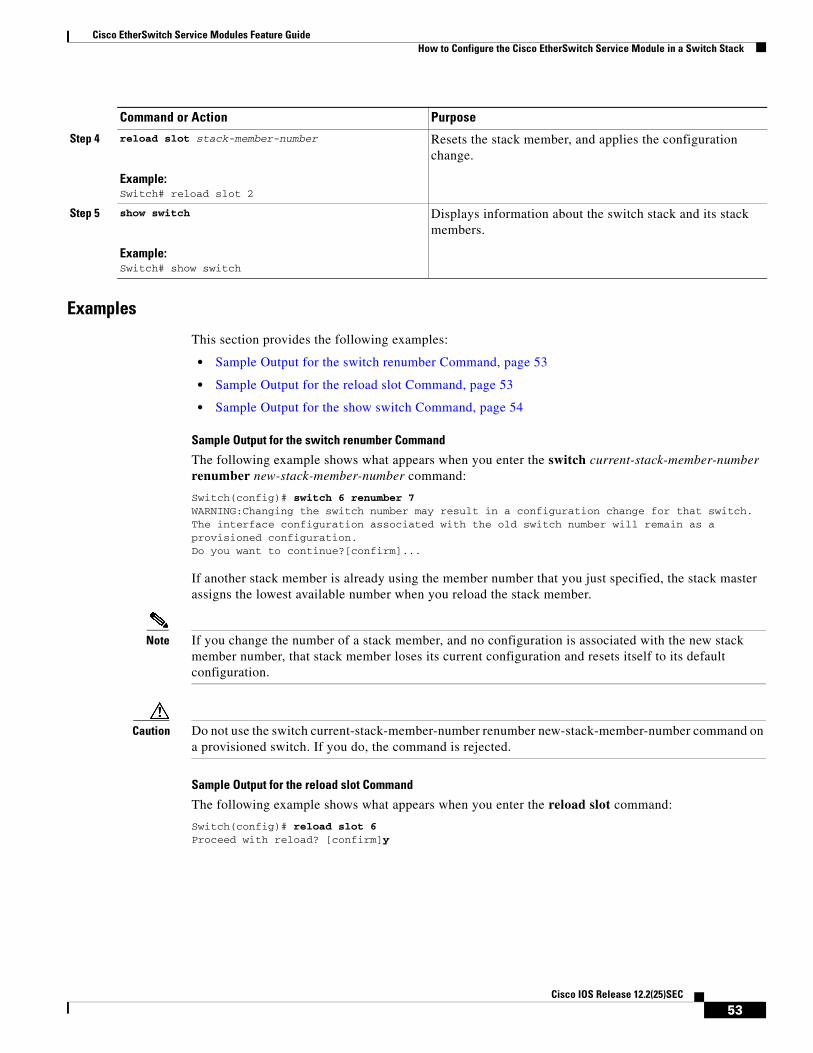
Cisco EtherSwitch Service Modules Feature GuideHow to Configure the Cisco EtherSwitch Service Module in a Switch Stack
Examples
This section provides the following examples:
• Sample Output for the switch renumber Command, page 53
• Sample Output for the reload slot Command, page 53
• Sample Output for the show switch Command, page 54
Sample Output for the switch renumber Command
The following example shows what appears when you enter the switch current-stack-member-number renumber new-stack-member-number command:
Switch(config)# switch 6 renumber 7WARNING:Changing the switch number may result in a configuration change for that switch.The interface configuration associated with the old switch number will remain as aprovisioned configuration.Do you want to continue?[confirm]...
If another stack member is already using the member number that you just specified, the stack master assigns the lowest available number when you reload the stack member.
Note If you change the number of a stack member, and no configuration is associated with the new stack member number, that stack member loses its current configuration and resets itself to its default configuration.
Caution Do not use the switch current-stack-member-number renumber new-stack-member-number command on a provisioned switch. If you do, the command is rejected.
Sample Output for the reload slot Command
The following example shows what appears when you enter the reload slot command:
Switch(config)# reload slot 6Proceed with reload? [confirm]y
Step 4 reload slot stack-member-number
Example:Switch# reload slot 2
Resets the stack member, and applies the configuration change.
Step 5 show switch
Example:Switch# show switch
Displays information about the switch stack and its stack members.
Command or Action Purpose
53Cisco IOS Release 12.2(25)SEC
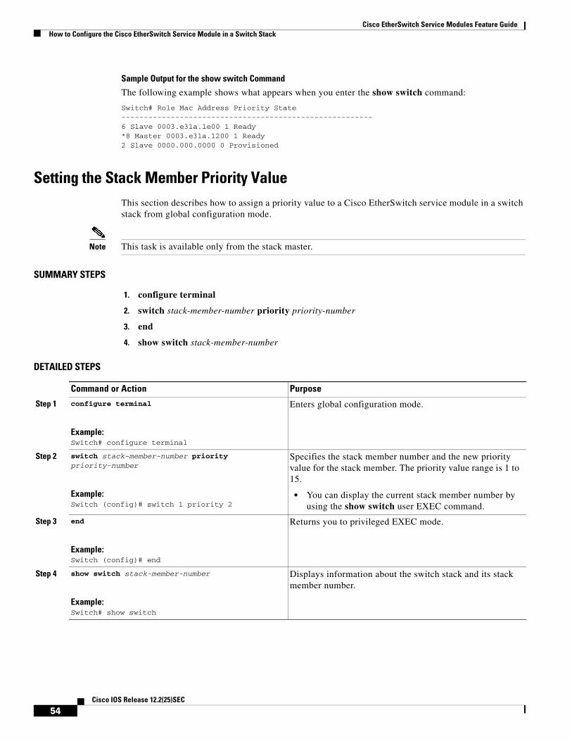
Cisco EtherSwitch Service Modules Feature GuideHow to Configure the Cisco EtherSwitch Service Module in a Switch Stack
Sample Output for the show switch Command
The following example shows what appears when you enter the show switch command:
Switch# Role Mac Address Priority State--------------------------------------------------------6 Slave 0003.e31a.1e00 1 Ready*8 Master 0003.e31a.1200 1 Ready2 Slave 0000.000.0000 0 Provisioned
Setting the Stack Member Priority ValueThis section describes how to assign a priority value to a Cisco EtherSwitch service module in a switch stack from global configuration mode.
Note This task is available only from the stack master.
SUMMARY STEPS
1. configure terminal
2. switch stack-member-number priority priority-number
3. end
4. show switch stack-member-number
DETAILED STEPS
Command or Action Purpose
Step 1 configure terminal
Example:Switch# configure terminal
Enters global configuration mode.
Step 2 switch stack-member-number priority priority-number
Example:Switch (config)# switch 1 priority 2
Specifies the stack member number and the new priority value for the stack member. The priority value range is 1 to 15.
• You can display the current stack member number by using the show switch user EXEC command.
Step 3 end
Example:Switch (config)# end
Returns you to privileged EXEC mode.
Step 4 show switch stack-member-number
Example:Switch# show switch
Displays information about the switch stack and its stack member number.
54Cisco IOS Release 12.2(25)SEC

Cisco EtherSwitch Service Modules Feature GuideHow to Configure the Cisco EtherSwitch Service Module in a Switch Stack
Examples
This section provides the following examples:
• Sample Output for the switch priority Command, page 55
• Sample Output for the show switch Command, page 55
Sample Output for the switch priority Command
The following example shows what appears when you enter the switch stack-member-number priority priority-number command:
Switch(config)# switch 2 priority 15Changing the Switch Priority of Switch Number 2 to 15Do you want to continue?[confirm]New Priority has been set successfully
Sample Output for the show switch Command
The following example shows what appears when you enter the show switch command:
Switch> show switch 6CurrentSwitch# Role Mac Address Priority State--------------------------------------------------------6 Slave 0003.e31a.1e00 1 Ready
Verifying Information About the Switch StackTo verify the configuration changes that you save after you reset a specific stack member or the switch stack configuration, use the show platform stack-manager all command.
For verification, Step 1 is useful for displaying all switch stack information. Step 2 is useful if you display information about a specific stack member, neighbors, or switch stack ports.
SUMMARY STEPS
1. show platform stack-manager {all | counters | trace [sdp [reverse] | state [reverse]]} [{begin | exclude | include} expression]
2. show switch
These show switch commands display more detailed switch stack information:
• show switch detail
• show switch neighbors
• show switch stack-ports
55Cisco IOS Release 12.2(25)SEC

Cisco EtherSwitch Service Modules Feature GuideHow to Configure the Cisco EtherSwitch Service Module in a Switch Stack
DETAILED STEPS
Step 1 Use the show platform stack-manager command to display platform-dependent switch-stack information. Use the show platform stack-manager all command to display all information for the entire switch stack, for example:
Switch# show platform stack-manager all
CurrentSwitch# Role Mac Address Priority State--------------------------------------------------------*1 Master 0000.0090.3080 1 Ready 2 Slave 000f.8f4e.2900 1 Ready
Stack Port Status NeighborsSwitch# Port 1 Port 2 Port 1 Port 2-------------------------------------------------------- 1 Ok Ok 2 2 2 Ok Ok 1 1
Stack Discovery Protocol View==============================================================
Switch Active Role Current Sequence DirtyNumber State Number Bit--------------------------------------------------------------------1 TRUE Master Ready 176 FALSE2 TRUE Slave Ready 177 FALSE
Stack State Machine View==============================================================
Switch Master/ Mac Address Version Uptime CurrentNumber Slave (maj.min) State---------------------------------------------------------------------1 Master 0000.0090.3080 1.9 1344 Ready2 Slave 000f.8f4e.2900 1.9 1338 Ready
Last Conflict Parameters
Switch Master/ Prio Default Image Uptime Mac AddressNumber Slave Config Type
Step 2 To display information about a stack member or the switch stack, use the following commands:
• Use the show switch command to display information related to the stack member or the switch stack.
Switch(config)# show switch 6CurrentSwitch# Role Mac Address Priority State--------------------------------------------------------6 Slave 0003.e31a.1e00 1 Ready
• Use the show switch neighbors user EXEC command to display detailed information about the neighbors of a switch stack:
56Cisco IOS Release 12.2(25)SEC
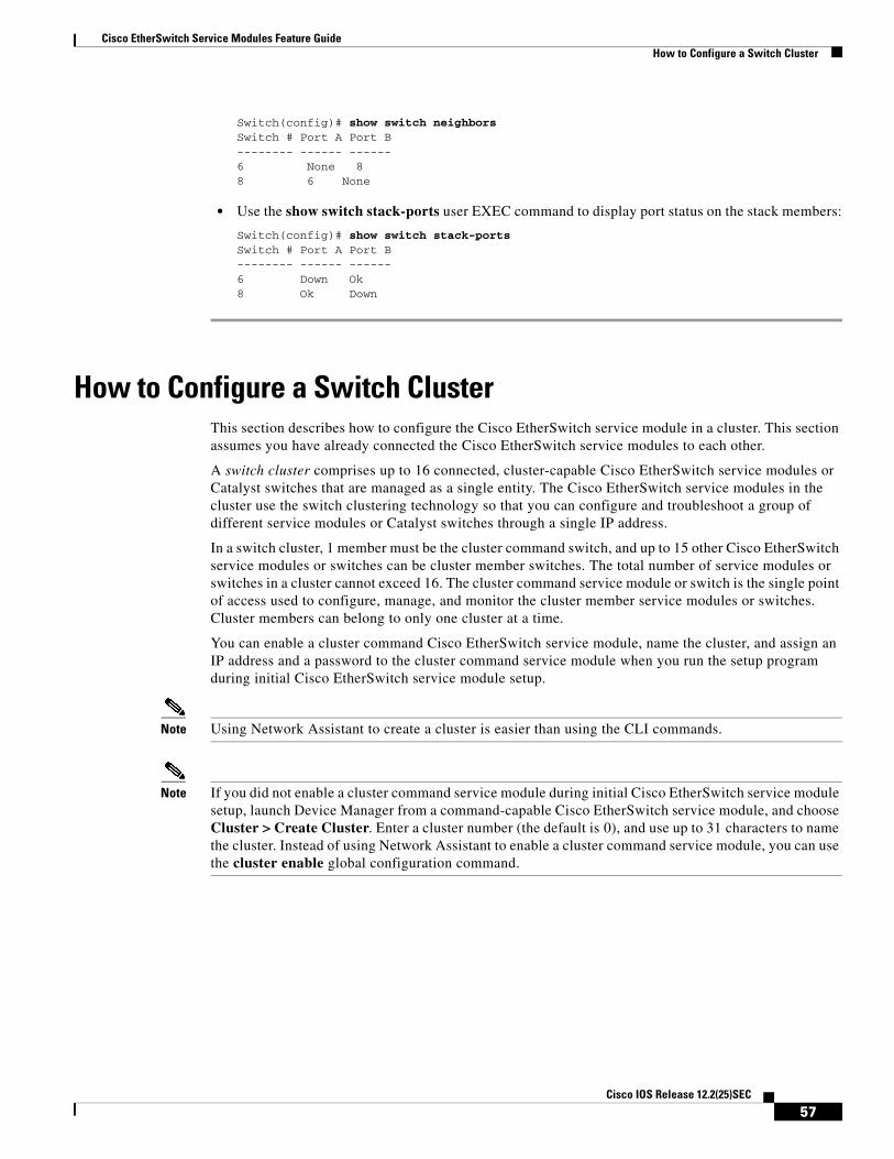
Cisco EtherSwitch Service Modules Feature GuideHow to Configure a Switch Cluster
Switch(config)# show switch neighborsSwitch # Port A Port B-------- ------ ------6 None 88 6 None
• Use the show switch stack-ports user EXEC command to display port status on the stack members:
Switch(config)# show switch stack-portsSwitch # Port A Port B-------- ------ ------6 Down Ok8 Ok Down
How to Configure a Switch ClusterThis section describes how to configure the Cisco EtherSwitch service module in a cluster. This section assumes you have already connected the Cisco EtherSwitch service modules to each other.
A switch cluster comprises up to 16 connected, cluster-capable Cisco EtherSwitch service modules or Catalyst switches that are managed as a single entity. The Cisco EtherSwitch service modules in the cluster use the switch clustering technology so that you can configure and troubleshoot a group of different service modules or Catalyst switches through a single IP address.
In a switch cluster, 1 member must be the cluster command switch, and up to 15 other Cisco EtherSwitch service modules or switches can be cluster member switches. The total number of service modules or switches in a cluster cannot exceed 16. The cluster command service module or switch is the single point of access used to configure, manage, and monitor the cluster member service modules or switches. Cluster members can belong to only one cluster at a time.
You can enable a cluster command Cisco EtherSwitch service module, name the cluster, and assign an IP address and a password to the cluster command service module when you run the setup program during initial Cisco EtherSwitch service module setup.
Note Using Network Assistant to create a cluster is easier than using the CLI commands.
Note If you did not enable a cluster command service module during initial Cisco EtherSwitch service module setup, launch Device Manager from a command-capable Cisco EtherSwitch service module, and choose Cluster > Create Cluster. Enter a cluster number (the default is 0), and use up to 31 characters to name the cluster. Instead of using Network Assistant to enable a cluster command service module, you can use the cluster enable global configuration command.
57Cisco IOS Release 12.2(25)SEC

Cisco EtherSwitch Service Modules Feature GuideHow to Configure a Switch Cluster
This section contains the following procedures:
• Using the CLI to Manage Switch Clusters, page 58
• Adding Cluster Members to the Cisco EtherSwitch Service Module, page 60
• Creating a Cluster Standby Group, page 62
Using the CLI to Manage Switch ClustersThis section shows how to use the CLI to manage switch clusters.
Prerequisites
Configure Cisco EtherSwitch service modules or switches that are members of a cluster from the CLI by first logging in to the cluster command service module or switch.
SUMMARY STEPS
1. rcommand {n | commander | mac-address hw-addr}
2. show version
3. exit
4. show cluster members [n | detail] [{begin | exclude | include} expression] (optional)
DETAILED STEPS
Command or Action Purpose
Step 1 rcommand
Example:Switch# rcommand 3
Starts a Telnet session to execute commands on a cluster member service module or switch from the cluster command service module or switch or the switch stack.
• To end the session, enter the exit command.
• If you do not know the number of the member service module, enter the show cluster members privileged EXEC command on the cluster command service module. The Telnet session accesses the member service module CLI at the same privilege level as on the cluster command service module. The Cisco IOS commands then operate as usual.
Step 2 show version
Example:Switch-3# show version
Displays version information for the hardware and firmware of the cluster member service module or cluster member switch.
58Cisco IOS Release 12.2(25)SEC
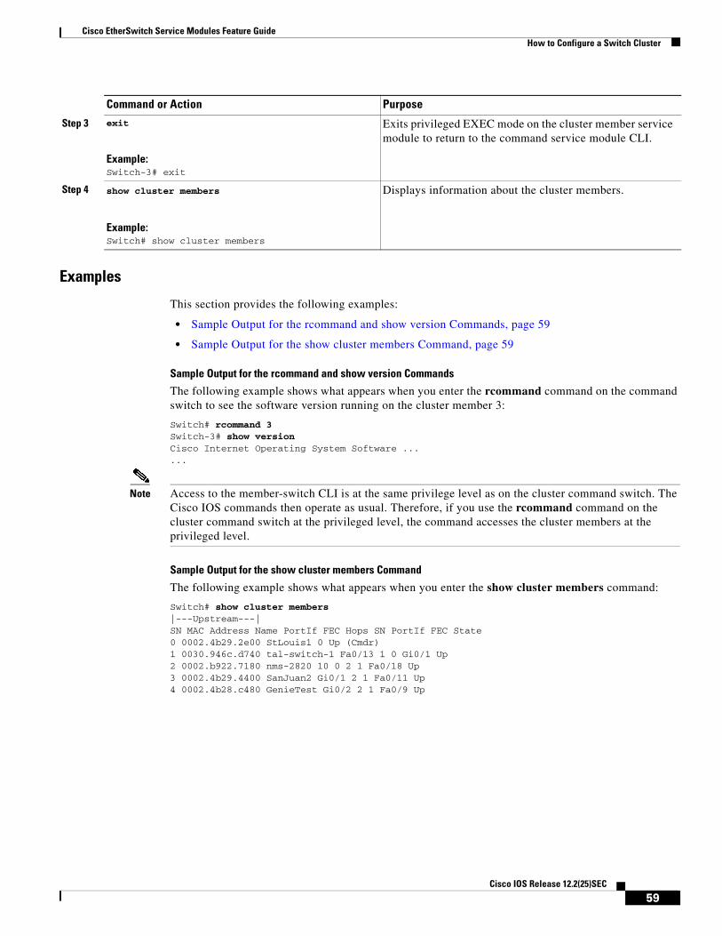
Cisco EtherSwitch Service Modules Feature GuideHow to Configure a Switch Cluster
Examples
This section provides the following examples:
• Sample Output for the rcommand and show version Commands, page 59
• Sample Output for the show cluster members Command, page 59
Sample Output for the rcommand and show version Commands
The following example shows what appears when you enter the rcommand command on the command switch to see the software version running on the cluster member 3:
Switch# rcommand 3Switch-3# show versionCisco Internet Operating System Software ......
Note Access to the member-switch CLI is at the same privilege level as on the cluster command switch. The Cisco IOS commands then operate as usual. Therefore, if you use the rcommand command on the cluster command switch at the privileged level, the command accesses the cluster members at the privileged level.
Sample Output for the show cluster members Command
The following example shows what appears when you enter the show cluster members command:
Switch# show cluster members|---Upstream---|SN MAC Address Name PortIf FEC Hops SN PortIf FEC State0 0002.4b29.2e00 StLouis1 0 Up (Cmdr)1 0030.946c.d740 tal-switch-1 Fa0/13 1 0 Gi0/1 Up2 0002.b922.7180 nms-2820 10 0 2 1 Fa0/18 Up3 0002.4b29.4400 SanJuan2 Gi0/1 2 1 Fa0/11 Up4 0002.4b28.c480 GenieTest Gi0/2 2 1 Fa0/9 Up
Step 3 exit
Example:Switch-3# exit
Exits privileged EXEC mode on the cluster member service module to return to the command service module CLI.
Step 4 show cluster members
Example:Switch# show cluster members
Displays information about the cluster members.
Command or Action Purpose
59Cisco IOS Release 12.2(25)SEC
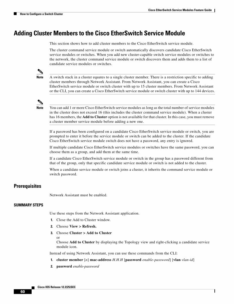
Cisco EtherSwitch Service Modules Feature GuideHow to Configure a Switch Cluster
Adding Cluster Members to the Cisco EtherSwitch Service ModuleThis section shows how to add cluster members to the Cisco EtherSwitch service module.
The cluster command service module or switch automatically discovers candidate Cisco EtherSwitch service modules or switches. When you add new cluster-capable switch service modules or switches to the network, the cluster command service module or switch discovers them and adds them to a list of candidate service modules or switches.
Note A switch stack in a cluster equates to a single cluster member. There is a restriction specific to adding cluster members through Network Assistant. From Network Assistant, you can create a Cisco EtherSwitch service module or switch cluster with up to 15 cluster members. From Network Assistant or the CLI, you can create a Cisco EtherSwitch service module or switch cluster with up to 144 devices.
Note You can add 1 or more Cisco EtherSwitch service modules as long as the total number of service modules in the cluster does not exceed 16 (this includes the cluster command service module). When a cluster has 16 members, the Add to Cluster option is not available for that cluster. In this case, you must remove a cluster member service module before adding a new one.
If a password has been configured on a candidate Cisco EtherSwitch service module or switch, you are prompted to enter it before the service module or switch can be added to the cluster. If the candidate Cisco EtherSwitch service module switch does not have a password, any entry is ignored.
If multiple candidate Cisco EtherSwitch service modules or switches have the same password, you can choose them as a group, and add them at the same time.
If a candidate Cisco EtherSwitch service module or switch in the group has a password different from that of the group, only that specific candidate service module or switch is not added to the cluster.
When a candidate service module or switch joins a cluster, it inherits the command service module or switch password.
Prerequisites
Network Assistant must be enabled.
SUMMARY STEPS
Use these steps from the Network Assistant application.
1. Close the Add to Cluster window.
2. Choose View > Refresh.
3. Choose Cluster > Add to ClusterorChoose Add to Cluster by displaying the Topology view and right-clicking a candidate service module icon.
Instead of using Network Assistant, you can use these commands from the CLI:
1. cluster member [n] mac-address H.H.H [password enable-password] [vlan vlan-id]
2. password enable-password
60Cisco IOS Release 12.2(25)SEC

Cisco EtherSwitch Service Modules Feature GuideHow to Configure a Switch Cluster
DETAILED STEPS FROM THE NETWORK ASSISTANT APPLICATION
Command or Action Purpose
Step 1 Close the Add to Cluster window. Closes the Add to Cluster window to view an updated list of cluster members.
Step 2 Choose View > Refresh. Displays an updated list of cluster members.
Step 3 Choose Cluster > Add to Cluster. Allows you to select a candidate service module from the cluster list.
• When you are at the Cluster > Add to Cluster window, click Add, and click OK. To add more than one candidate service module, press Ctrl, and make your choices, or press Shift, and choose the first and last service module in a range.
or
• Display the Topology view, right-click a candidate-service module icon, and choose Add to Cluster. In the Topology view, candidate service modules are cyan, and cluster member service modules are green. To add more than one candidate service module, press Ctrl, and left-click the candidates that you want to add.
Step 4 cluster member
Example:Switch(config)# cluster member mac-address 00E0.1E00.3333
Adds members to the cluster.
• The example shows how to add a switch with MAC address 00E0.1E00.3333 to the cluster. This switch does not have a password. The cluster command switch selects the next available member number and assigns it to the switch that is joining the cluster.
Step 5 password
Example:Switch(config)# cluster member 2 mac-address 00E0.1E00.2222 password key vlan 3
Allows you to enter a password if the candidate service module has a password.
• The example shows how to add a switch as member 2 with MAC address 00E0.1E00.2222 and the password key to a cluster. The cluster command switch adds the candidate to the cluster through VLAN 3.
61Cisco IOS Release 12.2(25)SEC
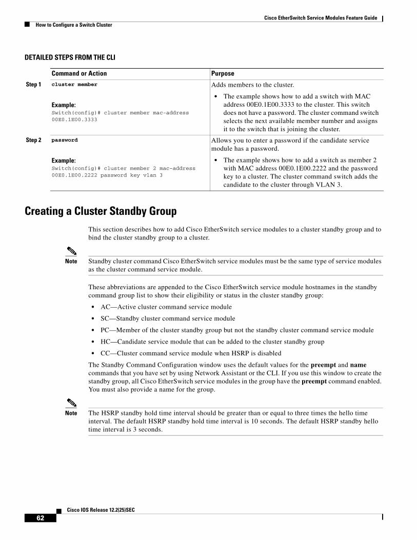
Cisco EtherSwitch Service Modules Feature GuideHow to Configure a Switch Cluster
DETAILED STEPS FROM THE CLI
Creating a Cluster Standby GroupThis section describes how to add Cisco EtherSwitch service modules to a cluster standby group and to bind the cluster standby group to a cluster.
Note Standby cluster command Cisco EtherSwitch service modules must be the same type of service modules as the cluster command service module.
These abbreviations are appended to the Cisco EtherSwitch service module hostnames in the standby command group list to show their eligibility or status in the cluster standby group:
• AC—Active cluster command service module
• SC—Standby cluster command service module
• PC—Member of the cluster standby group but not the standby cluster command service module
• HC—Candidate service module that can be added to the cluster standby group
• CC—Cluster command service module when HSRP is disabled
The Standby Command Configuration window uses the default values for the preempt and name commands that you have set by using Network Assistant or the CLI. If you use this window to create the standby group, all Cisco EtherSwitch service modules in the group have the preempt command enabled. You must also provide a name for the group.
Note The HSRP standby hold time interval should be greater than or equal to three times the hello time interval. The default HSRP standby hold time interval is 10 seconds. The default HSRP standby hello time interval is 3 seconds.
Command or Action Purpose
Step 1 cluster member
Example:Switch(config)# cluster member mac-address 00E0.1E00.3333
Adds members to the cluster.
• The example shows how to add a switch with MAC address 00E0.1E00.3333 to the cluster. This switch does not have a password. The cluster command switch selects the next available member number and assigns it to the switch that is joining the cluster.
Step 2 password
Example:Switch(config)# cluster member 2 mac-address 00E0.1E00.2222 password key vlan 3
Allows you to enter a password if the candidate service module has a password.
• The example shows how to add a switch as member 2 with MAC address 00E0.1E00.2222 and the password key to a cluster. The cluster command switch adds the candidate to the cluster through VLAN 3.
62Cisco IOS Release 12.2(25)SEC
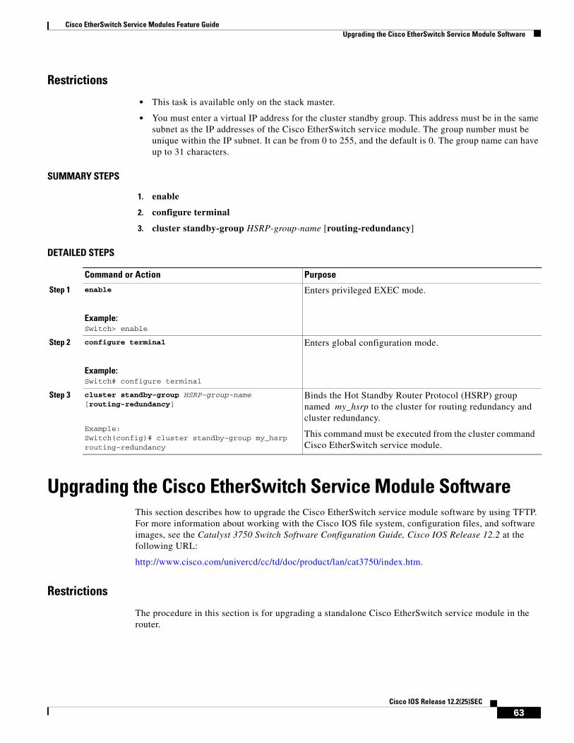
Cisco EtherSwitch Service Modules Feature GuideUpgrading the Cisco EtherSwitch Service Module Software
Restrictions
• This task is available only on the stack master.
• You must enter a virtual IP address for the cluster standby group. This address must be in the same subnet as the IP addresses of the Cisco EtherSwitch service module. The group number must be unique within the IP subnet. It can be from 0 to 255, and the default is 0. The group name can have up to 31 characters.
SUMMARY STEPS
1. enable
2. configure terminal
3. cluster standby-group HSRP-group-name [routing-redundancy]
DETAILED STEPS
Upgrading the Cisco EtherSwitch Service Module SoftwareThis section describes how to upgrade the Cisco EtherSwitch service module software by using TFTP. For more information about working with the Cisco IOS file system, configuration files, and software images, see the Catalyst 3750 Switch Software Configuration Guide, Cisco IOS Release 12.2 at the following URL:
http://www.cisco.com/univercd/cc/td/doc/product/lan/cat3750/index.htm.
Restrictions
The procedure in this section is for upgrading a standalone Cisco EtherSwitch service module in the router.
Command or Action Purpose
Step 1 enable
Example:Switch> enable
Enters privileged EXEC mode.
Step 2 configure terminal
Example:Switch# configure terminal
Enters global configuration mode.
Step 3 cluster standby-group HSRP-group-name [routing-redundancy]
Example:Switch(config)# cluster standby-group my_hsrp routing-redundancy
Binds the Hot Standby Router Protocol (HSRP) group named my_hsrp to the cluster for routing redundancy and cluster redundancy.
This command must be executed from the cluster command Cisco EtherSwitch service module.
63Cisco IOS Release 12.2(25)SEC

Cisco EtherSwitch Service Modules Feature GuideUpgrading the Cisco EtherSwitch Service Module Software
SUMMARY STEPS
1. enable
2. configure terminal
3. interface switch/slot/port
4. no switchport
5. ip address ip address/subnet mask
6. no shutdown
7. end
8. show flash
9. copy tftp: flash:
DETAILED STEPS
Command or Action Purpose
Step 1 enable
Example:Switch> enable
Enters privileged EXEC mode.
Step 2 configure terminal
Example:Switch# configure terminal
Enters global configuration mode.
Step 3 interface switch/slot/port
Example:Switch(config)# interface fastethernet 1/0/24
Enter interface configuration mode and places you at the Fast Ethernet 1/0/24 interface.
Step 4 no switchport
Example:Switch(config-if)# no switchport
Enables the routed port.
Step 5 ip address ip address/subnet mask
Example:Switch(config-if)# ip address 172.16.1.100 255.255.255.0
Sets a primary or secondary IP address for this interface.
Step 6 no shutdown
Example:Switch(config-if)# no shutdown
Enables the port that is connected to the TFTP server.
Step 7 end
Example:Switch(config)# end Switch#
Exits interface configuration mode, and returns to privileged EXEC mode.
64Cisco IOS Release 12.2(25)SEC

Cisco EtherSwitch Service Modules Feature GuideUpgrading the Cisco EtherSwitch Service Module Software
Examples
This section provides the following examples:
• Sample Output for the show run interface fastethernet Command, page 65
• Sample Output for the ping tftpserver Command, page 65
• Sample Output for the show flash: Command, page 66
• Sample Output for the copy tftp: flash: Command, page 66
Sample Output for the show run interface fastethernet Command
The following example shows what appears when you enter the show run interface fastEthernet command:
Switch# show run interface fa1/0/24Building configuration...Current configuration : 87 bytes!interface FastEthernet1/0/24 no switchport ip address 172.16.1.100 255.255.255.0end
Sample Output for the ping tftpserver Command
The following example shows what appears when you enter the ping tftpserver command:
Switch# ping tftpserver
Type escape sequence to abort.Sending 5, 100-byte ICMP Echos to 172.16.1.100, timeout is 2 seconds:!!!!!Success rate is 100 percent (5/5), round-trip min/avg/max = 1/2/9 msCopy the image from the tftp server to the switch flash using standard tftp copy procedure.
Step 8 show run interface fastethernet switch/slot/port
Example:Switch# show run interface fastEthernet 1/0/24
Shows the configuration applied on this interface.
Step 9 ping tftpserver
Example:Switch# ping tftpserver
Pings the TFTP server. This command copies an image from a TFTP server to flash memory.
Step 10 show flash:
Example:Switch# show flash:
Displays a list of all files and directories in the Cisco EtherSwitch service module flash memory.
Step 11 copy tftp: flash:
Example:Switch# copy tftp: flash:
Copies an image from a TFTP server to flash memory.
Command or Action Purpose
65Cisco IOS Release 12.2(25)SEC

Cisco EtherSwitch Service Modules Feature GuideTroubleshooting the Cisco EtherSwitch Service Module Software
Sample Output for the show flash: Command
The following example shows what appears when you enter the show flash: command:
Switch# show flash:
Directory of flash:/
3 -rwx 4815232 Jan 1 1970 00:10:53 +00:00 c3825-i5-mz.050404 4 -rwx 6496 May 11 2004 10:43:15 +00:00 vlan.dat 5 -rwx 2377 Mar 1 1993 04:33:45 +00:00 config.text 6 -rwx 5 Mar 1 1993 04:33:46 +00:00 private-config.text
15998976 bytes total (6355968 bytes free)Switch#
Sample Output for the copy tftp: flash: Command
The following example shows what appears when you enter the copy tftp: flash: command:
Switch# copy tftp: flash:
Address or name of remote host []? Tftpserver Source filename [] /xyz/c3825-i5-mz.032304Destination filename [c3825-i5-mz.032304]? Accessing tftp://tftpserver/xyz/c3825-i5-mz.032304...Loading mirage/switch/bin/c3825-i5-mz.032304 from 172.16.1.100 (via FastEthernet1/0/24): !!!!!!!!!!!!!!!!!!!!!!!!!!!!!!!!!!!!!!!!!!!!!!!!!!!!!!!!!!!!!!!!!!!!!!!!!!!!!!!!!!!!!!!!!!!!!!!!!!!!!!!!!!!!!!!!!!!!!!!!!!!!!!!!!!!!!!!!!!!!!!!!!!!!!!!!!!!!!!!!!!!!!!!!!!!!!!!!!!!!!!!!!!!!!!!!!!!!!!!!!!!!!!!!!!!!!!!!!!!!!!!!!!!!!!!!!!!!!!!!!!!!!!!!!!!!!!!!!!!!!!!!!!!!!!!!!!!!!!!!!!!!!!!!!!!!![OK - 4814025 bytes]
4814025 bytes copied in 99.481 secs (48391 bytes/sec)Switch#
Troubleshooting the Cisco EtherSwitch Service Module Software
This section describes how to troubleshoot the Cisco EtherSwitch service module:
• Recovering from a Corrupted Software Image Using Xmodem, page 67
• Recovering from a Lost or Forgotten Password, page 72
• Recovering from a Lost or Forgotten Password When Password Recovery Is Disabled, page 76
For more information about these and other troubleshooting topics, see the Catalyst 3750 Switch Software Configuration Guide, Cisco IOS Release 12.2 at the following URL:
http://www.cisco.com/univercd/cc/td/doc/product/lan/cat3750/index.htm
66Cisco IOS Release 12.2(25)SEC

Cisco EtherSwitch Service Modules Feature GuideTroubleshooting the Cisco EtherSwitch Service Module Software
Recovering from a Corrupted Software Image Using XmodemThis section describes how to recover from a corrupted software image by using Xmodem.
Note The router should have the switch image in the router flash memory or have network connectivity to the TFTP server.
The Cisco EtherSwitch service module software can be corrupted while upgrading the software, by downloading the wrong file to the Cisco EtherSwitch service module, and by deleting the image file. In all of these cases, the service module does not pass the power-on self-test (POST), and there is no connectivity.
This procedure uses the Xmodem Protocol to recover from a corrupt or wrong image file. Many software packages support the Xmodem Protocol, and this procedure is largely dependent on the emulation software you are using.
To start the Xmodem protocol process, issue the password reset command. After you issue the password reset command, this message appears:
Password reset process is complete...
The system has been interrupted prior to initializing theflash filesystem. The following commands will initializethe flash filesystem, and finish loading the operating system software:
flash_init load_helper boot
Switch:
Restrictions
This procedure is recommended only for recovery of a corrupted image. To perform this procedure, the Cisco EtherSwitch service module must be at the boot loader prompt, and the console from the router to the Cisco EtherSwitch service module must be disconnected for the Xmodem Protocol to work.
SUMMARY STEPS
1. service-module interface slot/port password-reset
2. flash_init
3. load_helper filesystem:/file-url ... (optional)
4. control+6 x (Use x to get back to the router prompt.)
5. disconnect
6. copy flash: xmodem: (Use this command to download the software image from the router flash memory. Use this command from the router prompt.)
or
copy tftp: xmodem: (Use this command to download the software image from a TFTP server. Use this command only if the image is not on the router flash memory.)
67Cisco IOS Release 12.2(25)SEC

Cisco EtherSwitch Service Modules Feature GuideTroubleshooting the Cisco EtherSwitch Service Module Software
7. service-module interface slot/port session
8. dir flash:
9. boot flash: image
DETAILED STEPS
Command or Action Purpose
Step 1 service-module interface slot/port password-reset
Example:Router# service-module gigabitethernet2/0 password-reset
Ensures that the switch stays at the boot loader prompt, so that you can copy a new image through the Xmodem Protocol.
Step 2 flash_init
Example:Switch: flash_init
Initializes the flash memory file system on the switch.
Step 3 load_helper filesystem:/file-url ...
Example:Switch: load_helper flash: xyz
Loads and initializes one or more helper images.
Step 4 control+6 x
Example:Switch: control+6 x
Returns you to the router console while keeping the console session to the switch intact.
(Use x to get back to the router prompt.)
Step 5 disconnect
Example:Router# disconnect 1
Disconnects the switch session to begin the Xmodem download.
Step 6 copy flash: xmodem:
Example:Router# copy flash: xmodem:
or
Starts the file transfer from the router flash memory by using the Xmodem Protocol from the router prompt.
copy tftp: xmodem:
Example:Router# copy tftp: xmodem:
Starts the file transfer from a TFTP server from the router prompt.
Step 7 service-module interface slot/port session
Example:Router# service-module gigabitethernet1/0 session
Connects to the service module and opens a Cisco EtherSwitch service module session.
68Cisco IOS Release 12.2(25)SEC

Cisco EtherSwitch Service Modules Feature GuideTroubleshooting the Cisco EtherSwitch Service Module Software
Troubleshooting
If the downloaded image (files and directories) are not in flash memory on the Cisco EtherSwitch service module, repeat Step 1 through Step 6. If the procedure fails again, ensure that your TFTP connection is up and that your TFTP session is open when you download the image.
Examples
This section provides the following examples:
• Sample Output for the copy flash: xmodem Command, page 69
• Sample Output for the copy tftp: xmodem: Command, page 70
• Sample Output for the service-module session Command on the Cisco EtherSwitch Service Module, page 71
• Sample Output for the dir flash: Command on the Cisco EtherSwitch Service Module, page 71
• Sample Output for the service-module password-reset Command on the Cisco EtherSwitch Service Module, page 71
• Sample Output for the flash_init Command on the Cisco EtherSwitch Service Module, page 72
Sample Output for the copy flash: xmodem Command
The following example shows what appears when you enter the copy flash: xmodem command:
Router# copy flash: xmodem
**** WARNING ****x/ymodem is a slow transfer protocol limited to the current speedsettings of the auxiliary/console ports. The use of the auxiliaryport for this download is strongly recommended.During the course of the download no exec input/output will beavailable.---- ******* ----
Proceed? [confirm]
You are prompted for the source filename and destination filename:
Source filename [loader_bs.img]?Destination filename [loader_bs.img]?
You are prompted for the Cisco EtherSwitch service module slot number:
Service Module slot number? [1]:
Step 8 dir flash:
Example:switch> dir flash:
Displays a list of all files and directories in flash memory on the service module.
Step 9 boot flash: image
Example:switch> boot flash:c3825-i5-mz.050404
Boots the Cisco EtherSwitch service module image if all files and directories are in flash memory on the service module.
Command or Action Purpose
69Cisco IOS Release 12.2(25)SEC

Cisco EtherSwitch Service Modules Feature GuideTroubleshooting the Cisco EtherSwitch Service Module Software
You are prompted for the service module interface number. Accept the default:
Service Module interface number? [0]:
You are prompted to confirm the buffer. Accept the default:
1k buffer? [confirm]
You are prompted for the max retry count. Accept the default:
Max Retry Count [10]:
You are prompted to confirm the transfer to the Cisco EtherSwitch service module:
Xmodem send on slot 2 interface 0. Please be sure there is enough space on receiving side.Continue? [confirm]
The following appears when the image is downloaded to the service module:
Ready to send file...........C!!!!!!!!!!!!!!!!!!!!!!!!!!!!!!!!!!!!!!!!!!!!!!!!!!!!!!!!!!!!!!!!!!!!!!!!!!!!!!!!!!!!!!!!!!!!!!!!!!!!!!!!!!!!!!!!!!!!!!!!!!!!!!!!!!!!!!!!!!!!!!!!!!!!!!!!!!!!!!!!!!!!!!!!!!!!!!!!!!!!!!!!!!!!!!!!!!!!!!!!!!!!!!!!!!!!!!!!!!!!!!!!!!!!!!!!!!!!!!!!!!!!!!!!!!!!!!!!262144 bytes copied in 101.744 secs (2577 bytes/sec)
Sample Output for the copy tftp: xmodem: Command
The following example shows what appears when you enter the copy tftp: xmodem: command:
Router# copy tftp: xmodem:
**** WARNING ****x/ymodem is a slow transfer protocol limited to the current speedsettings of the auxiliary/console ports. The use of the auxiliaryport for this download is strongly recommended.During the course of the download no exec input/output will beavailable.---- ******* ----
Proceed? [confirm]
You are prompted for the IP address of the TFTP server:
Address or name of remote host []? 223.255.254.254
You are prompted for the source filename and destination filename:
Source filename [loader_bs.img]?Destination filename [loader_bs.img]?
The following appears when you are connected to the TFTP server:
Accessing tftp://223.255.254.254/anyname/loader_bs.img...
You are prompted for the Cisco EtherSwitch service module slot number:
Service Module slot number? [1]:2
You are prompted for the service module interface number. Accept the default:
Service Module interface number? [0]:
You are prompted to confirm the buffer. Accept the default:
1k buffer? [confirm]
70Cisco IOS Release 12.2(25)SEC

Cisco EtherSwitch Service Modules Feature GuideTroubleshooting the Cisco EtherSwitch Service Module Software
You are prompted for the max retry count. Accept the default:
Max Retry Count [10]:
You are prompted to confirm the transfer to the Cisco EtherSwitch service module:
Xmodem send on slot 2 interface 0. Please be sure there is enough space on receiving side.Continue? [confirm]
The following appears when the image is downloaded to the service module:
Ready to send file...........Loading anyname/loader_bs.img from 223.255.254.254 (via GigabitEthernet0/0):!C!.!!!!!!!!!!!!!!!!!!!!!!!!!!!!!!.!!!!!!!!!!!!!!!!!!!!!!!!!!!!!!.!!!!!!!!!!!!!!!!!!!!!!!!!!!!!.!!!!!!!!!!!!!!!!!!!!!!!!!!!!!!.!!!!!!!!!!!!!!!!!!!!!!!!!!!!!.!!!!!!!!!!!!!!!!!!!!!!!!!!!!!!.!!!!!!!!!!!!!!!!!!!!!!!!!!!!!!.!!!!!!!!!!!!!!!!!!!!!!!!!!!!!.!!!!!!!!!!!!!!!!!!!!!!!!!!!!!!.!!!!!!!!!!!!.!!!!!!.!!!!!!!!!!!!!!!!!!!!![OK - 262144 bytes]!
Verifying checksum... OK (0x4F76)262144 bytes copied in 22.368 secs (11720 bytes/sec)
Sample Output for the service-module session Command on the Cisco EtherSwitch Service Module
The following example shows what appears when you enter the service-module session command:
Router# service-module gigabitethernet1/0 session Trying 41.0.0.1, 2130 ... Open
Switch:
Sample Output for the dir flash: Command on the Cisco EtherSwitch Service Module
The following example shows what appears when you enter the dir flash: command:
rommon> dir flash:Directory of flash:/
4 -rwx 2056 Mar 1 1993 00:01:29 +00:00 vlan.dat6 -rwx 6636204 Mar 1 1993 00:19:19 +00:00 c3750-i5-mz.122204 7 -rwx 1709 Jan 12 2005 00:56:39 +00:00 config.text 8 -rwx 5 Jan 12 2005 00:56:39 +00:00 private-config.text
32514048 bytes total (19113472 bytes free)
Sample Output for the service-module password-reset Command on the Cisco EtherSwitch Service Module
The following example shows what appears when you enter the service-module password-reset command:
Router# service-module gigabitethernet2/0 password-resetDo you want to proceed with password reset process?[confirm]Starting password reset process...Wait for 50 secs for password reset process to completeRouter#[Resuming connection 1 to 100.0.2.1 ... ]
Password reset process is complete...
Base ethernet MAC Address: 00:00:00:20:60:80Xmodem file system is available.The password-recovery mechanism is enabled.
The system has been interrupted prior to initializing theflash filesystem. The following commands will initialize
71Cisco IOS Release 12.2(25)SEC
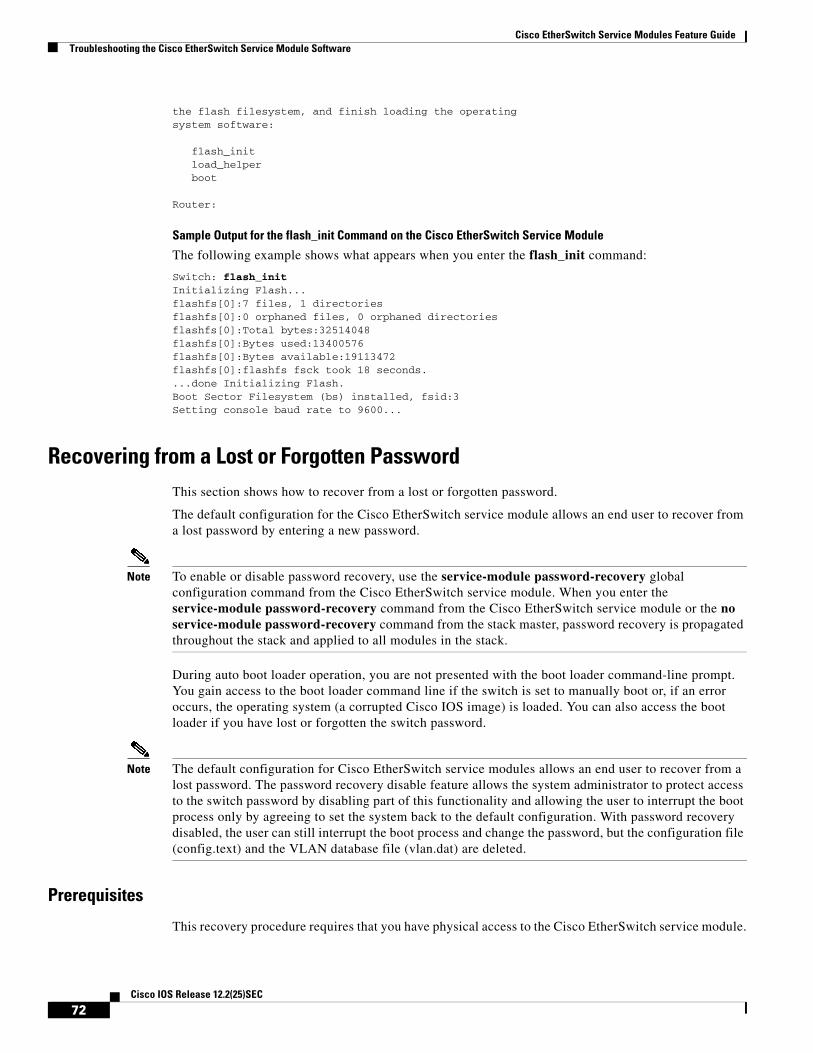
Cisco EtherSwitch Service Modules Feature GuideTroubleshooting the Cisco EtherSwitch Service Module Software
the flash filesystem, and finish loading the operatingsystem software:
flash_init load_helper boot
Router:
Sample Output for the flash_init Command on the Cisco EtherSwitch Service Module
The following example shows what appears when you enter the flash_init command:
Switch: flash_initInitializing Flash...flashfs[0]:7 files, 1 directoriesflashfs[0]:0 orphaned files, 0 orphaned directoriesflashfs[0]:Total bytes:32514048flashfs[0]:Bytes used:13400576flashfs[0]:Bytes available:19113472flashfs[0]:flashfs fsck took 18 seconds....done Initializing Flash.Boot Sector Filesystem (bs) installed, fsid:3Setting console baud rate to 9600...
Recovering from a Lost or Forgotten PasswordThis section shows how to recover from a lost or forgotten password.
The default configuration for the Cisco EtherSwitch service module allows an end user to recover from a lost password by entering a new password.
Note To enable or disable password recovery, use the service-module password-recovery global configuration command from the Cisco EtherSwitch service module. When you enter the service-module password-recovery command from the Cisco EtherSwitch service module or the no service-module password-recovery command from the stack master, password recovery is propagated throughout the stack and applied to all modules in the stack.
During auto boot loader operation, you are not presented with the boot loader command-line prompt. You gain access to the boot loader command line if the switch is set to manually boot or, if an error occurs, the operating system (a corrupted Cisco IOS image) is loaded. You can also access the boot loader if you have lost or forgotten the switch password.
Note The default configuration for Cisco EtherSwitch service modules allows an end user to recover from a lost password. The password recovery disable feature allows the system administrator to protect access to the switch password by disabling part of this functionality and allowing the user to interrupt the boot process only by agreeing to set the system back to the default configuration. With password recovery disabled, the user can still interrupt the boot process and change the password, but the configuration file (config.text) and the VLAN database file (vlan.dat) are deleted.
Prerequisites
This recovery procedure requires that you have physical access to the Cisco EtherSwitch service module.
72Cisco IOS Release 12.2(25)SEC

Cisco EtherSwitch Service Modules Feature GuideTroubleshooting the Cisco EtherSwitch Service Module Software
SUMMARY STEPS
1. service-module interface slot/port session
2. dir flash:
3. service-module interface slot/port password-reset
4. flash_init
5. (Optional) load_helper filesystem:/file-url ...
6. rename
7. boot
8. copy flash:
9. configure terminal
10. enable secret password
11. exit
12. copy running-configuration startup-configuration
13. reload
DETAILED STEPS
Command or Action Purpose
Step 1 service-module interface slot/port session
Example:Router# service-module gigabitethernet1/0 session
Connects to the service module and opens a Cisco EtherSwitch service module session.
Step 2 dir flash:
Example:rommon> dir flash:
Displays a list of all files and directories in flash memory on the service module.
Step 3 service-module interface slot/port password-reset
Example:Router# service-module gigabitethernet1/0 password-reset
Enables password recovery.
Step 4 flash_init
Example:Switch: flash_init
Initializes the flash memory file system.
Step 5 load_helper filesystem:/file-url ...
Example:Switch: load_helper flash:xyz
Loads and initializes one or more helper images.
73Cisco IOS Release 12.2(25)SEC

Cisco EtherSwitch Service Modules Feature GuideTroubleshooting the Cisco EtherSwitch Service Module Software
Step 6 rename
Example:Switch: rename flash:config.text flash:config.text.old
Renames the configuration file to config.text.old.
• Before continuing to the next command, power up any connected stack members and wait until they have completely initialized.
Step 7 boot [-x] [-v] [device:][imagename]
Example:Switch: boot
Use the boot command to boot up an external process.
Step 8 copy flash:
Example:Switch: copy flash:config.text system:running-config
Copies the configuration file into memory.
Step 9 configure terminal
Example:Switch# configure terminal
Enters global configuration mode.
Step 10 enable secret password
Example:Switch(config): enable secret 5 $1$LiBw$0Xc1wyT.PXPkuhFwqyhVi0
Sets the password.
• The secret password can be from 1 to 25 alphanumeric characters.
• It can start with a number.
• It is case sensitive.
• It allows spaces but ignores leading spaces.
Step 11 exit
Example:Switch(config): exit
Returns you to privileged EXEC mode.
Command or Action Purpose
74Cisco IOS Release 12.2(25)SEC

Cisco EtherSwitch Service Modules Feature GuideTroubleshooting the Cisco EtherSwitch Service Module Software
Step 12 copy running-configuration startup-configuration
Example:Switch: copy running-config startup-config
Copies the configuration from the running configuration file to the switch startup configuration file.
• This procedure is likely to leave your Cisco EtherSwitch service module virtual interface in a shut down state.
• You can see which interface is in this state by entering the show running-configuration privileged EXEC command.
• To reenable the interface, enter the interface vlan vlan-id global configuration command, and specify the VLAN ID of the shut down interface. With the Cisco EtherSwitch service module in interface configuration mode, enter the no shutdown command.
Step 13 reload
Example:Switch: reload
Reloads the switch stack.
Command or Action Purpose
75Cisco IOS Release 12.2(25)SEC
Cisco EtherSwitch Service Modules Feature GuideTroubleshooting the Cisco EtherSwitch Service Module Software
Recovering from a Lost or Forgotten Password When Password Recovery Is Disabled
This section shows how to recover from a lost or forgotten password when password recovery is disabled.
When password recovery is disabled, access to the boot loader prompt through the password-recovery mechanism is disallowed even though the password-recovery mechanism has been triggered. If you agree to let the system be reset to the default system configuration, access to the boot loader prompt is then allowed, and you can set the environment variables.
Prerequisites
This recovery procedure requires that you have physical access to the Cisco EtherSwitch service module or switch.
SUMMARY STEPS
1. service-module interface slot/port password-reset
1. service-module interface slot/port session
2. dir flash:
3. (Optional) load_helper filesystem:/file-url ...
4. boot
5. enable
6. configure terminal
7. enable secret password
8. exit
9. copy running-configuration startup-configuration
10. reload
11. (Optional) set
76Cisco IOS Release 12.2(25)SEC
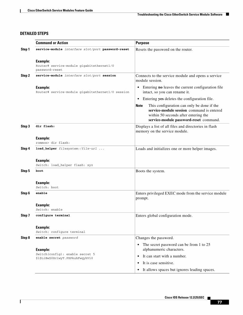
Cisco EtherSwitch Service Modules Feature GuideTroubleshooting the Cisco EtherSwitch Service Module Software
DETAILED STEPS
Command or Action Purpose
Step 1 service-module interface slot/port password-reset
Example:Router# service-module gigabitethernet1/0 password-reset
Resets the password on the router.
Step 2 service-module interface slot/port session
Example:Router# service-module gigabitethernet1/0 session
Connects to the service module and opens a service module session.
• Entering no leaves the current configuration file intact, so you can rename it.
• Entering yes deletes the configuration file.
Note This configuration can only be done if the service-module session command is entered within 50 seconds after entering the service-module password-reset command.
Step 3 dir flash:
Example:rommon> dir flash:
Displays a list of all files and directories in flash memory on the service module.
Step 4 load_helper filesystem:/file-url ...
Example:Switch: load_helper flash: xyz
Loads and initializes one or more helper images.
Step 5 boot
Example:Switch: boot
Boots the system.
Step 6 enable
Example:Switch: enable
Enters privileged EXEC mode from the service module prompt.
Step 7 configure terminal
Example:Switch: configure terminal
Enters global configuration mode.
Step 8 enable secret password
Example:Switch(config): enable secret 5 $1$LiBw$0Xc1wyT.PXPkuhFwqyhVi0
Changes the password.
• The secret password can be from 1 to 25 alphanumeric characters.
• It can start with a number.
• It is case sensitive.
• It allows spaces but ignores leading spaces.
77Cisco IOS Release 12.2(25)SEC

Cisco EtherSwitch Service Modules Feature GuideSwitch Stack Configuration Scenarios
Example
Sample Output for the set Command
The following example shows what appears when you enter the set command:
Switch: set
BAUD=9600MAC_ADDR=00:00:00:20:30:80MANUAL_BOOT=yesSDM_TEMPLATE_ID=0SWITCH_NUMBER=2SWITCH_PRIORITY=1
Switch Stack Configuration ScenariosTable 4 provides scenarios of how switch stack features are determined. Most of the scenarios assume that at least two Cisco EtherSwitch service modules are connected to each other through their Cisco StackWise ports.
Step 9 exit
Example:Switch(config): exit
Returns you to privileged EXEC mode.
Step 10 copy running-configuration startup-configuration
Example:Switch: copy running-config startup-config
Copies the configuration from the running configuration file to the switch startup configuration file.
• This procedure is likely to leave your Cisco EtherSwitch service module virtual interface in a shut down state.
• You can see which interface is in this state by entering the show running-configuration privileged EXEC command.
• To reenable the interface, enter the interface vlan vlan-id global configuration command, and specify the VLAN ID of the shut down interface. With the Cisco EtherSwitch service module in interface configuration mode, enter the no shutdown command.
Step 11 reload
Example:Switch# reload
Reloads the switch stack.
Step 12 set
Example:Switch# set
Lists all environment variables, including the current baud rate.
Command or Action Purpose
78Cisco IOS Release 12.2(25)SEC

Cisco EtherSwitch Service Modules Feature GuideSwitch Stack Configuration Scenarios
Table 4 Switch Stack Configuration Scenarios
Scenario Action Result
Stack master election specifically determined by existing stack masters
Connect two powered-up switch stacks through the Cisco StackWise ports.
Only one of the two stack masters becomes the new stack master.
Stack master election specifically determined by the stack member priority value
1. Connect two Cisco EtherSwitch service modules through their Cisco StackWise ports.
2. Use the switch stack-member-number priority priority-number global configuration command to set one stack member with a higher member priority value.
3. Restart both stack members at the same time.
The stack member with the higher priority value is elected stack master.
Stack master election specifically determined by the configuration file
Assuming that both stack members have the same priority value:
1. Make sure that one stack member has a default configuration and that the other stack member has a saved (nondefault) configuration file.
2. Restart both stack members at the same time.
The stack member with the saved configuration file is elected stack master.
Stack master election specifically determined by the cryptographic IP services image
Assuming that all stack members have the same priority value:
1. Make sure that one stack member has the cryptographic IP services image installed and that the other stack member has the noncryptographic IP services image installed.
2. Restart both stack members at the same time.
The stack member with the cryptographic IP services image is elected stack master.
Stack master election specifically determined by the IP services image
Assuming that all stack members have the same priority value:
1. Make sure that one stack member has the noncryptographic IP services image installed and that the other stack member has the cryptographic IP base image installed.
2. Restart both stack members at the same time.
The stack member with the noncryptographic IP services image is elected stack master.
79Cisco IOS Release 12.2(25)SEC
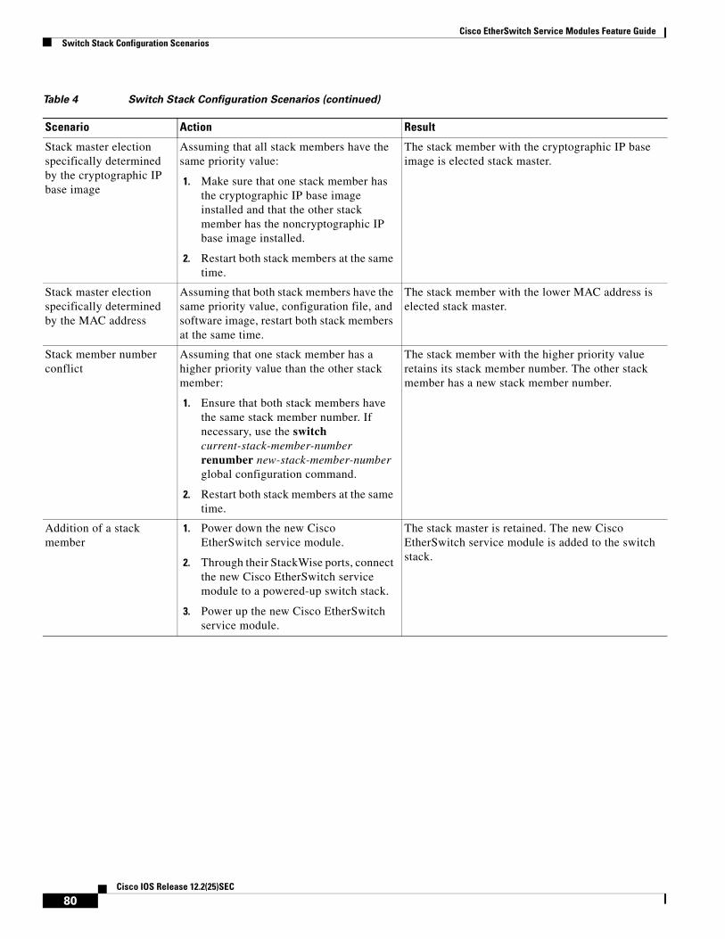
Cisco EtherSwitch Service Modules Feature GuideSwitch Stack Configuration Scenarios
Stack master election specifically determined by the cryptographic IP base image
Assuming that all stack members have the same priority value:
1. Make sure that one stack member has the cryptographic IP base image installed and that the other stack member has the noncryptographic IP base image installed.
2. Restart both stack members at the same time.
The stack member with the cryptographic IP base image is elected stack master.
Stack master election specifically determined by the MAC address
Assuming that both stack members have the same priority value, configuration file, and software image, restart both stack members at the same time.
The stack member with the lower MAC address is elected stack master.
Stack member number conflict
Assuming that one stack member has a higher priority value than the other stack member:
1. Ensure that both stack members have the same stack member number. If necessary, use the switch current-stack-member-number renumber new-stack-member-number global configuration command.
2. Restart both stack members at the same time.
The stack member with the higher priority value retains its stack member number. The other stack member has a new stack member number.
Addition of a stack member
1. Power down the new Cisco EtherSwitch service module.
2. Through their StackWise ports, connect the new Cisco EtherSwitch service module to a powered-up switch stack.
3. Power up the new Cisco EtherSwitch service module.
The stack master is retained. The new Cisco EtherSwitch service module is added to the switch stack.
Table 4 Switch Stack Configuration Scenarios (continued)
Scenario Action Result
80Cisco IOS Release 12.2(25)SEC
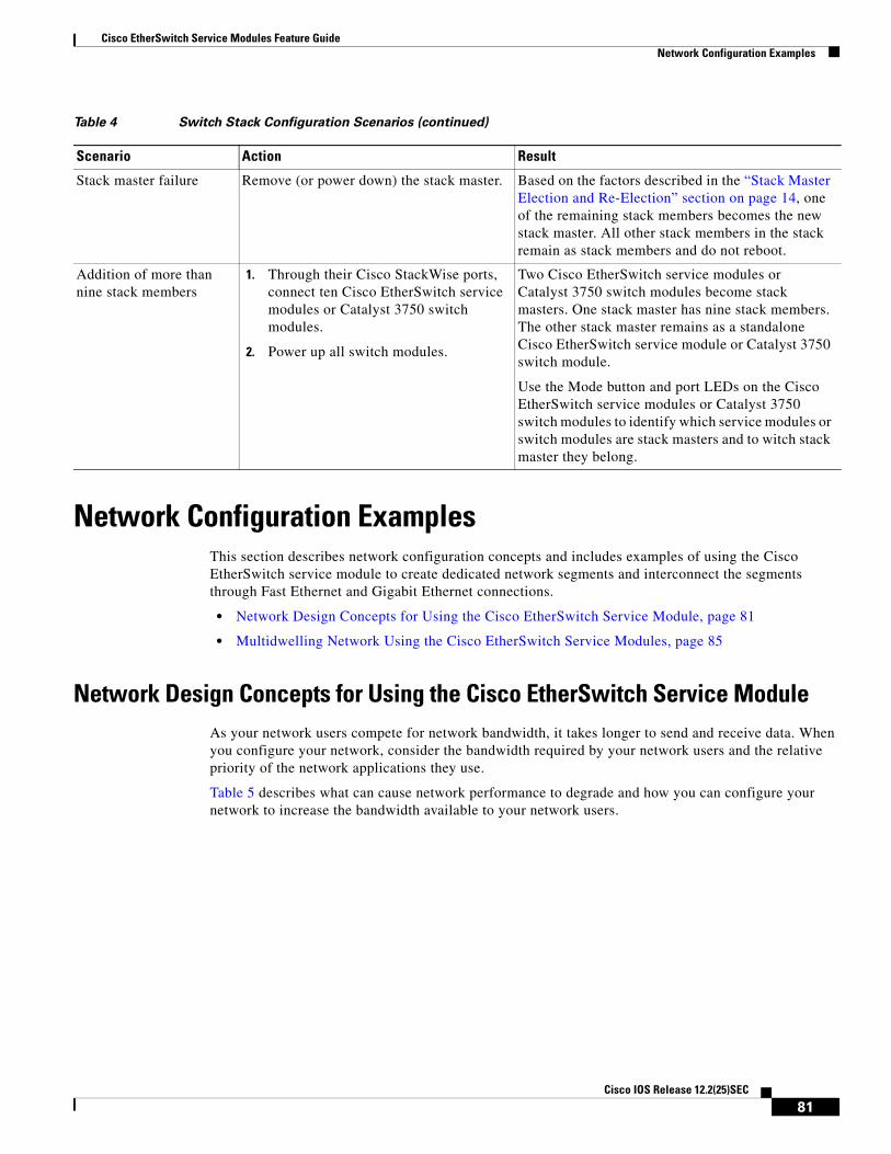
Cisco EtherSwitch Service Modules Feature GuideNetwork Configuration Examples
Network Configuration ExamplesThis section describes network configuration concepts and includes examples of using the Cisco EtherSwitch service module to create dedicated network segments and interconnect the segments through Fast Ethernet and Gigabit Ethernet connections.
• Network Design Concepts for Using the Cisco EtherSwitch Service Module, page 81
• Multidwelling Network Using the Cisco EtherSwitch Service Modules, page 85
Network Design Concepts for Using the Cisco EtherSwitch Service ModuleAs your network users compete for network bandwidth, it takes longer to send and receive data. When you configure your network, consider the bandwidth required by your network users and the relative priority of the network applications they use.
Table 5 describes what can cause network performance to degrade and how you can configure your network to increase the bandwidth available to your network users.
Stack master failure Remove (or power down) the stack master. Based on the factors described in the “Stack Master Election and Re-Election” section on page 14, one of the remaining stack members becomes the new stack master. All other stack members in the stack remain as stack members and do not reboot.
Addition of more than nine stack members
1. Through their Cisco StackWise ports, connect ten Cisco EtherSwitch service modules or Catalyst 3750 switch modules.
2. Power up all switch modules.
Two Cisco EtherSwitch service modules or Catalyst 3750 switch modules become stack masters. One stack master has nine stack members. The other stack master remains as a standalone Cisco EtherSwitch service module or Catalyst 3750 switch module.
Use the Mode button and port LEDs on the Cisco EtherSwitch service modules or Catalyst 3750 switch modules to identify which service modules or switch modules are stack masters and to witch stack master they belong.
Table 4 Switch Stack Configuration Scenarios (continued)
Scenario Action Result
81Cisco IOS Release 12.2(25)SEC
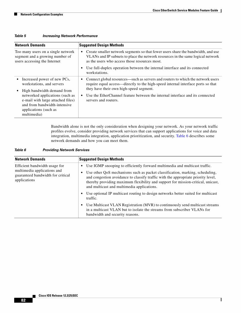
Cisco EtherSwitch Service Modules Feature GuideNetwork Configuration Examples
Bandwidth alone is not the only consideration when designing your network. As your network traffic profiles evolve, consider providing network services that can support applications for voice and data integration, multimedia integration, application prioritization, and security. Table 6 describes some network demands and how you can meet them.
Table 5 Increasing Network Performance
Network Demands Suggested Design Methods
Too many users on a single network segment and a growing number of users accessing the Internet
• Create smaller network segments so that fewer users share the bandwidth, and use VLANs and IP subnets to place the network resources in the same logical network as the users who access those resources most.
• Use full-duplex operation between the internal interface and its connected workstations.
• Increased power of new PCs, workstations, and servers
• High bandwidth demand from networked applications (such as e-mail with large attached files) and from bandwidth-intensive applications (such as multimedia)
• Connect global resources—such as servers and routers to which the network users require equal access—directly to the high-speed internal interface ports so that they have their own high-speed segment.
• Use the EtherChannel feature between the internal interface and its connected servers and routers.
Table 6 Providing Network Services
Network Demands Suggested Design Methods
Efficient bandwidth usage for multimedia applications and guaranteed bandwidth for critical applications
• Use IGMP snooping to efficiently forward multimedia and multicast traffic.
• Use other QoS mechanisms such as packet classification, marking, scheduling, and congestion avoidance to classify traffic with the appropriate priority level, thereby providing maximum flexibility and support for mission-critical, unicast, and multicast and multimedia applications.
• Use optional IP multicast routing to design networks better suited for multicast traffic.
• Use Multicast VLAN Registration (MVR) to continuously send multicast streams in a multicast VLAN but to isolate the streams from subscriber VLANs for bandwidth and security reasons.
82Cisco IOS Release 12.2(25)SEC
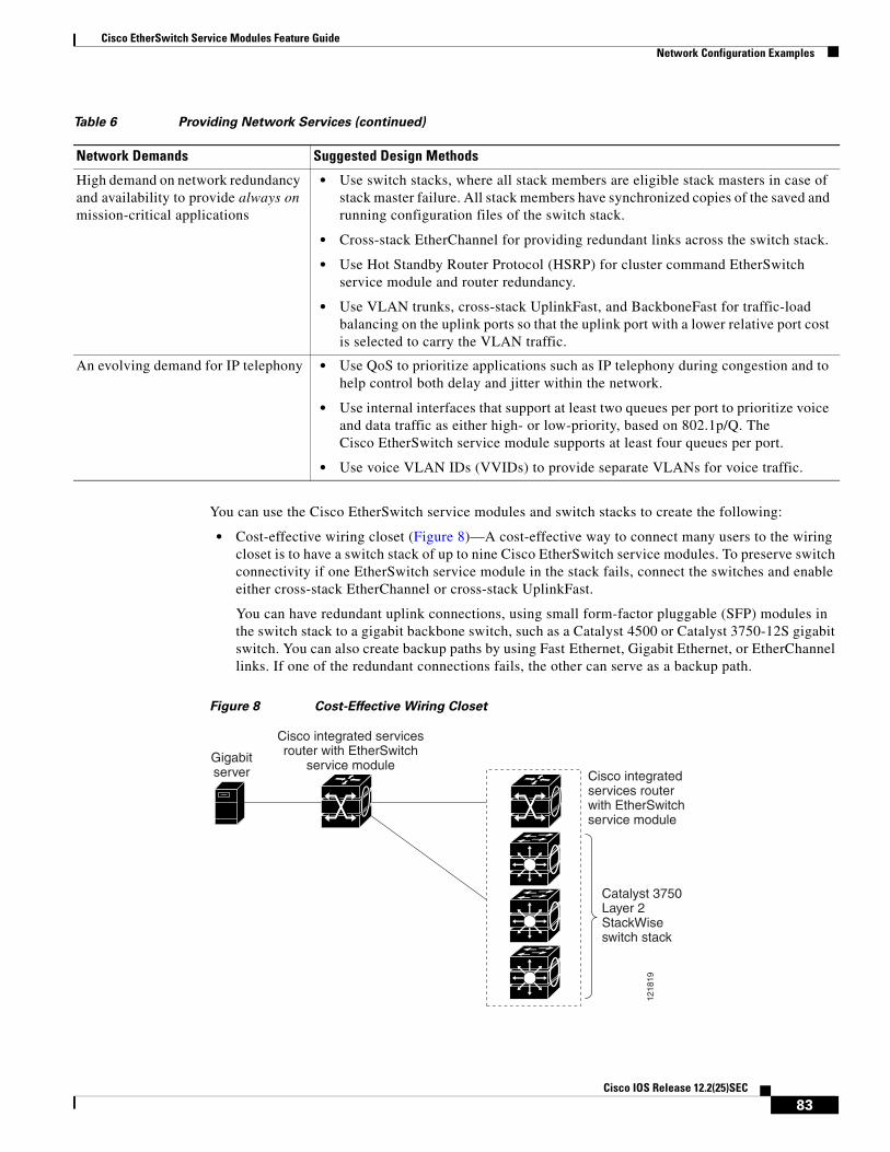
Cisco EtherSwitch Service Modules Feature GuideNetwork Configuration Examples
You can use the Cisco EtherSwitch service modules and switch stacks to create the following:
• Cost-effective wiring closet (Figure 8)—A cost-effective way to connect many users to the wiring closet is to have a switch stack of up to nine Cisco EtherSwitch service modules. To preserve switch connectivity if one EtherSwitch service module in the stack fails, connect the switches and enable either cross-stack EtherChannel or cross-stack UplinkFast.
You can have redundant uplink connections, using small form-factor pluggable (SFP) modules in the switch stack to a gigabit backbone switch, such as a Catalyst 4500 or Catalyst 3750-12S gigabit switch. You can also create backup paths by using Fast Ethernet, Gigabit Ethernet, or EtherChannel links. If one of the redundant connections fails, the other can serve as a backup path.
Figure 8 Cost-Effective Wiring Closet
High demand on network redundancy and availability to provide always on mission-critical applications
• Use switch stacks, where all stack members are eligible stack masters in case of stack master failure. All stack members have synchronized copies of the saved and running configuration files of the switch stack.
• Cross-stack EtherChannel for providing redundant links across the switch stack.
• Use Hot Standby Router Protocol (HSRP) for cluster command EtherSwitch service module and router redundancy.
• Use VLAN trunks, cross-stack UplinkFast, and BackboneFast for traffic-load balancing on the uplink ports so that the uplink port with a lower relative port cost is selected to carry the VLAN traffic.
An evolving demand for IP telephony • Use QoS to prioritize applications such as IP telephony during congestion and to help control both delay and jitter within the network.
• Use internal interfaces that support at least two queues per port to prioritize voice and data traffic as either high- or low-priority, based on 802.1p/Q. The Cisco EtherSwitch service module supports at least four queues per port.
• Use voice VLAN IDs (VVIDs) to provide separate VLANs for voice traffic.
Table 6 Providing Network Services (continued)
Network Demands Suggested Design Methods
Catalyst 3750Layer 2StackWiseswitch stack
Cisco integrated servicesrouter with EtherSwitch
service moduleCisco integratedservices routerwith EtherSwitchservice module
Gigabitserver
1218
19
83Cisco IOS Release 12.2(25)SEC
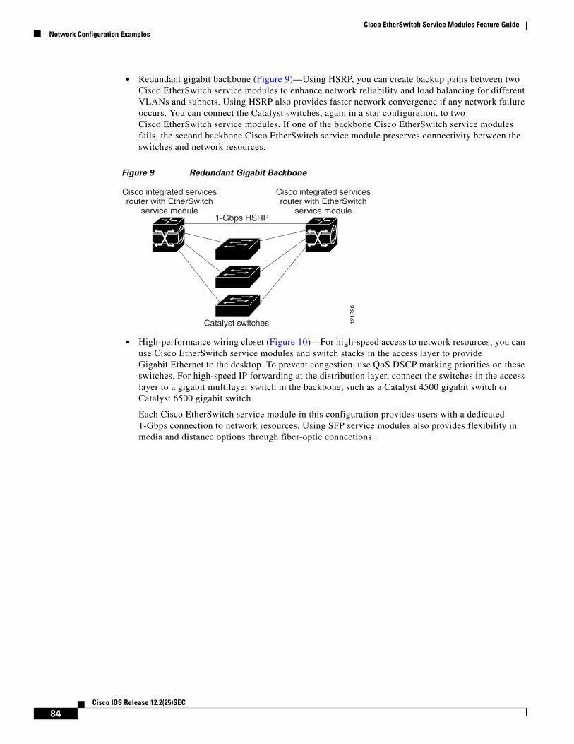
Cisco EtherSwitch Service Modules Feature GuideNetwork Configuration Examples
• Redundant gigabit backbone (Figure 9)—Using HSRP, you can create backup paths between two Cisco EtherSwitch service modules to enhance network reliability and load balancing for different VLANs and subnets. Using HSRP also provides faster network convergence if any network failure occurs. You can connect the Catalyst switches, again in a star configuration, to two Cisco EtherSwitch service modules. If one of the backbone Cisco EtherSwitch service modules fails, the second backbone Cisco EtherSwitch service module preserves connectivity between the switches and network resources.
Figure 9 Redundant Gigabit Backbone
• High-performance wiring closet (Figure 10)—For high-speed access to network resources, you can use Cisco EtherSwitch service modules and switch stacks in the access layer to provide Gigabit Ethernet to the desktop. To prevent congestion, use QoS DSCP marking priorities on these switches. For high-speed IP forwarding at the distribution layer, connect the switches in the access layer to a gigabit multilayer switch in the backbone, such as a Catalyst 4500 gigabit switch or Catalyst 6500 gigabit switch.
Each Cisco EtherSwitch service module in this configuration provides users with a dedicated 1-Gbps connection to network resources. Using SFP service modules also provides flexibility in media and distance options through fiber-optic connections.
1-Gbps HSRP
1218
20
Cisco integrated servicesrouter with EtherSwitch
service module
Cisco integrated servicesrouter with EtherSwitch
service module
Catalyst switches
84Cisco IOS Release 12.2(25)SEC

Cisco EtherSwitch Service Modules Feature GuideNetwork Configuration Examples
Figure 10 High-Performance Wiring Closet
Multidwelling Network Using the Cisco EtherSwitch Service ModulesA growing segment of residential and commercial customers is requiring high-speed access to Ethernet metropolitan-area networks (MANs). Figure 11 shows a configuration for a Gigabit Ethernet MAN ring using multilayer switch stacks as aggregation switches in the mini-point-of-presence (POP) location. These switches are connected through 1000BASE-X SFP service module ports.
All ports on the residential service modules are configured as 802.1Q trunks with protected port and STP root guard features enabled. The protected port feature provides security and isolation between ports on the switch, ensuring that subscribers cannot view packets destined for other subscribers. STP root guard prevents unauthorized devices from becoming the STP root switch. All ports have IGMP snooping or CGMP enabled for multicast traffic management. ACLs on the uplink ports to the aggregating Catalyst 3750 multilayer switches provide security and bandwidth management.
Gigabitservers
1218
21
Cisco integrated servicesrouter with EtherSwitch
service module
Catalyst 3750multilayer
StackWiseswitch stack
Internet
Cisco IPphones Workstations
runningCisco SoftPhone
software
Aironet wirelessaccess points
IP IP
85Cisco IOS Release 12.2(25)SEC

Cisco EtherSwitch Service Modules Feature GuideNetwork Configuration Examples
Figure 11 Cisco EtherSwitch Service Modules in a MAN Configuration
1218
22
ServiceProviderPOP
Mini-POPGigabit MAN
Residentiallocation
Catalyst 3750StackWise
switch stack
Cisco integrated servicesrouter with EtherSwitch
service module
Cisco integrated servicesrouter with EtherSwitch
service module
Catalystswitches
Catalyst 6500switches
Cisco 12000Gigabit switch routers
Si Si
Si
Residentialgateway (hub)
Set-top box
TV
PC
Set-top box
TV
86Cisco IOS Release 12.2(25)SEC

Cisco EtherSwitch Service Modules Feature GuideAdditional References
Additional References
Related Documents
Technical Assistance
Related Topic Document Title
Hardware installation instructions for network modules Cisco Interface Cards Installation Guide
General information about voice configuration and command reference.
Cisco IOS Voice Command Reference
Description Link
Technical Assistance Center (TAC) home page, containing 30,000 pages of searchable technical content, including links to products, technologies, solutions, technical tips, and tools. Registered Cisco.com users can log in from this page to access even more content.
http://www.cisco.com/public/support/tac/home.shtml
CCVP, the Cisco logo, and Welcome to the Human Network are trademarks of Cisco Systems, Inc.; Changing the Way We Work, Live, Play, and Learn isa service mark of Cisco Systems, Inc.; and Access Registrar, Aironet, Catalyst, CCDA, CCDP, CCIE, CCIP, CCNA, CCNP, CCSP, Cisco, the CiscoCertified Internetwork Expert logo, Cisco IOS, Cisco Press, Cisco Systems, Cisco Systems Capital, the Cisco Systems logo, Cisco Unity,Enterprise/Solver, EtherChannel, EtherFast, EtherSwitch, Fast Step, Follow Me Browsing, FormShare, GigaDrive, HomeLink, Internet Quotient, IOS,iPhone, IP/TV, iQ Expertise, the iQ logo, iQ Net Readiness Scorecard, iQuick Study, LightStream, Linksys, MeetingPlace, MGX, Networkers,Networking Academy, Network Registrar, PIX, ProConnect, ScriptShare, SMARTnet, StackWise, The Fastest Way to Increase Your Internet Quotient,and TransPath are registered trademarks of Cisco Systems, Inc. and/or its affiliates in the United States and certain other countries.
All other trademarks mentioned in this document or Website are the property of their respective owners. The use of the word partner does not imply apartnership relationship between Cisco and any other company. (0711R)
87Cisco IOS Release 12.2(25)SEC

Cisco EtherSwitch Service Modules Feature GuideAdditional References
88Cisco IOS Release 12.2(25)SEC