Embed Size (px)
Citation preview
Americas Headquarters:Cisco Systems, Inc., 170 West Tasman Drive, San Jose, CA 95134-1706 USA
Configuring the Cisco Gigabit EtherSwitch EHWIC
First Published: July 30, 2010
This document provides configuration tasks for the Cisco Gigabit EtherSwitch enhanced high-speed WAN interface cards (EHWICs) supported on Cisco Integrated Services Routers Generation 2 (ISR G2).
Feature History for Cisco Gigabit EtherSwitch Enhanced High-Speed Interface Cards
Finding Support Information for Platforms and Cisco IOS Software Images
Use Cisco Feature Navigator to find information about platform support and Cisco IOS software image support. Access Cisco Feature Navigator at http://www.cisco.com/go/fn. You must have an account on Cisco.com. If you do not have an account or have forgotten your username or password, click Cancel at the login dialog box and follow the instructions that appear.
ContentsThe following sections provide information about the Cisco EtherSwitch EHWICs.
• Prerequisites for Gigabit EtherSwitch EHWICs, page 2
• Restrictions for Gigabit EtherSwitch EHWICs, page 2
• Information About Gigabit EtherSwitch EHWICs, page 2
• How to Configure Gigabit EtherSwitch EHWICs, page 3
• Configuration Examples for Gigabit EtherSwitch EHWICs, page 78
• Additional References, page 88
Release Modification
15.1(2)T This feature was introduced.
Configuring the Cisco Gigabit EtherSwitch EHWICPrerequisites for Gigabit EtherSwitch EHWICs
2Configuring the Cisco Gigabit EtherSwitch EHWIC
OL-23155-01
Prerequisites for Gigabit EtherSwitch EHWICsThe following are prerequisites to configuring Cisco Gigabit EtherSwitch EHWICs:
• Configure IP routing on the host router. (See Cisco IOS IP Configuration Guide at
http://www.cisco.com/en/US/products/ps10592/products_installation_and_configuration_guides_list.html.)
• Install the Cisco Gigabit EtherSwitch EHWIC on a Cisco ISR G2 platform running Cisco IOS 15.1(2)T or later.
Restrictions for Gigabit EtherSwitch EHWICsThe following restrictions apply to the Cisco Gigabit EtherSwitch EHWICs:
• The Cisco Gigabit EtherSwitch EHWIC cannot function with the following modules in the chassis at the same time:
– HWIC-4ESW
– HWIC-4ESW-POE
– HWIC-D-9ESW
– HWIC-D-9ESW-POE
– NM-16ESW
– NM-36ESW
• On the Cisco 1905, 1906, and 1921 ISR platforms, only a single gigabit EtherSwitch EHWIC is supported.
• Online insertion and removal (OIR) is not supported.
• When Ethernet switches have been installed and configured in a host router, do not perform OIR of the CompactFlash memory card in the router. OIR of the CompactFlash memory card compromises the configuration of the Ethernet switches.
• VLAN trunking protocol (VTP) pruning is not supported.
• No more than 200 secure MAC addresses per platform are supported by an EtherSwitch EHWIC.
Information About Gigabit EtherSwitch EHWICsCisco Gigabit EHWICs are 10/100/1000 BaseT Layer 2 gigabit Ethernet switches with Layer 3 routing capability. Layer 3 routing is done on the host router.
Note To link a port on a Cisco Gigabit EtherSwitch EHWIC to an enhanced EtherSwitch service module or EtherSwitch service module in the same VTP domain, the port and the Cisco Gigabit EtherSwitch EHWIC should be stacked.
The gigabit EHWICs are also available with a power over Ethernet (PoE) module to provide inline power for IP telephones.
Configuring the Cisco Gigabit EtherSwitch EHWICHow to Configure Gigabit EtherSwitch EHWICs
3Configuring the Cisco Gigabit EtherSwitch EHWIC
OL-23155-01
To configure the Cisco Gigabit EHWICs, you should understand the following concepts:
How to Configure Gigabit EtherSwitch EHWICsThe following sections provide the configuration tasks for the EtherSwitch EHWICs:
• Configuring VLANs, page 4
• Configuring VLAN Trunking Protocol, page 8
• Configuring Layer 2 Interfaces, page 10
• Configuring 802.1x Authentication, page 19
• Configuring Spanning Tree, page 29
• Configuring MAC Table Manipulation, page 35
• Configuring Cisco Discovery Protocol, page 38
• Configuring the Switched Port Analyzer, page 38
• Configuring Power Management on the Interface, page 40
• Configuring IP Multicast Layer 3 Switching, page 42
• Configuring IGMP Snooping, page 45
• Configuring Per-Port Storm-Control, page 50
• Configuring Fallback Bridging, page 52
• Configuring Separate Voice and Data Subnets, page 65
• Managing the EtherSwitch EHWIC, page 67
• Configuring Port Security, page 78
Concepts Link
VLANs http://www.cisco.com/en/US/docs/ios/lanswitch/configuration/guide/lsw_enet_switch_net_external_docbase_0900e4b18090920b_4container_external_docbase_0900e4b18096f791.html
Inline Power for Cisco IP Phones
Layer 2 Ethernet Switching
802.1x Authentication
Spanning Tree Protocol
Cisco Discovery Protocol
Switched Port Analyzer
IGMP Snooping
Storm Control
Fallback Bridging
Configuring the Cisco Gigabit EtherSwitch EHWICHow to Configure Gigabit EtherSwitch EHWICs
4Configuring the Cisco Gigabit EtherSwitch EHWIC
OL-23155-01
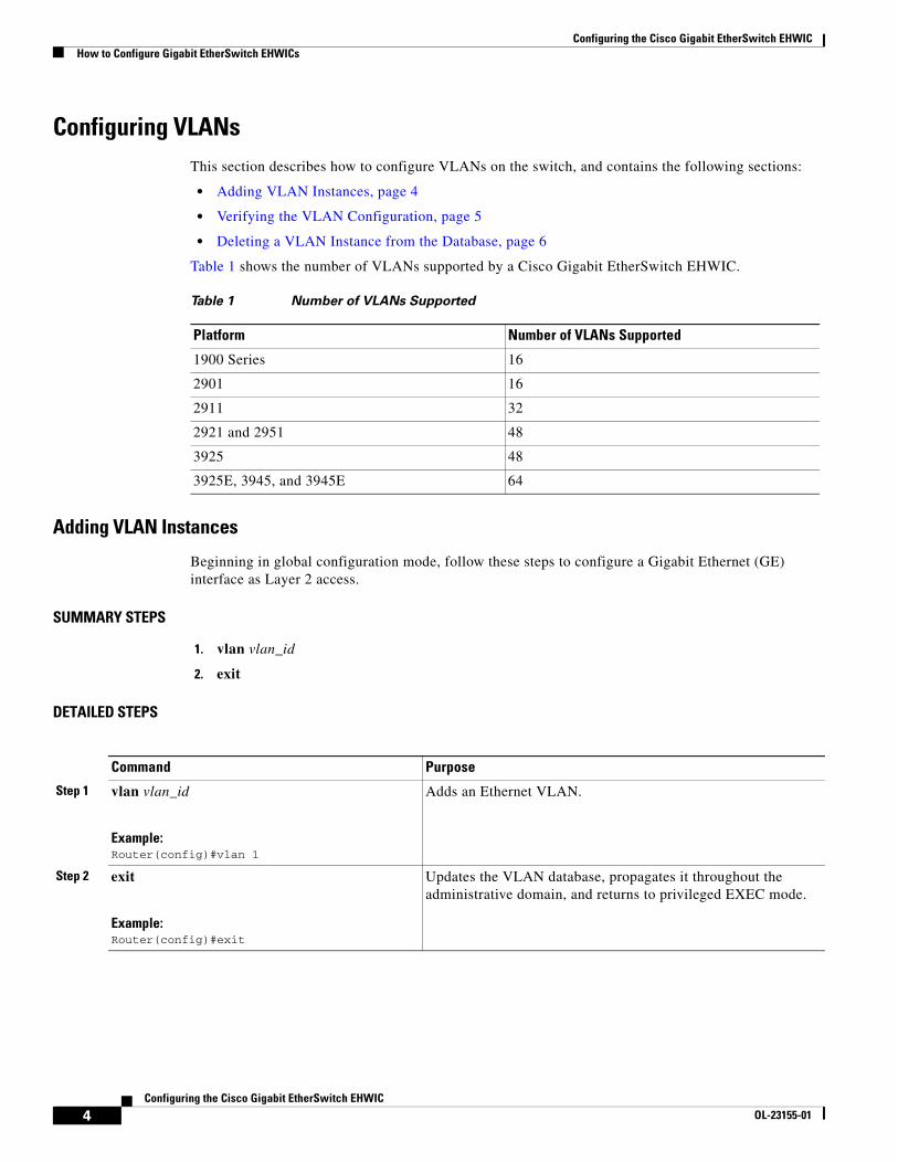
Configuring VLANsThis section describes how to configure VLANs on the switch, and contains the following sections:
• Adding VLAN Instances, page 4
• Verifying the VLAN Configuration, page 5
• Deleting a VLAN Instance from the Database, page 6
Table 1 shows the number of VLANs supported by a Cisco Gigabit EtherSwitch EHWIC.
Adding VLAN Instances
Beginning in global configuration mode, follow these steps to configure a Gigabit Ethernet (GE) interface as Layer 2 access.
SUMMARY STEPS
1. vlan vlan_id
2. exit
DETAILED STEPS
Table 1 Number of VLANs Supported
Platform Number of VLANs Supported
1900 Series 16
2901 16
2911 32
2921 and 2951 48
3925 48
3925E, 3945, and 3945E 64
Command Purpose
Step 1 vlan vlan_id
Example:Router(config)#vlan 1
Adds an Ethernet VLAN.
Step 2 exit
Example:Router(config)#exit
Updates the VLAN database, propagates it throughout the administrative domain, and returns to privileged EXEC mode.
Configuring the Cisco Gigabit EtherSwitch EHWICHow to Configure Gigabit EtherSwitch EHWICs
5Configuring the Cisco Gigabit EtherSwitch EHWIC
OL-23155-01
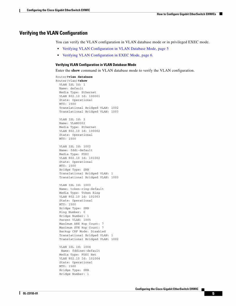
Verifying the VLAN Configuration
You can verify the VLAN configuration in VLAN database mode or in privileged EXEC mode.
• Verifying VLAN Configuration in VLAN Database Mode, page 5
• Verifying VLAN Configuration in EXEC Mode, page 6.
Verifying VLAN Configuration in VLAN Database Mode
Enter the show command in VLAN database mode to verify the VLAN configuration.
Router#vlan databaseRouter(vlan)#show VLAN ISL Id: 1 Name: default Media Type: Ethernet VLAN 802.10 Id: 100001 State: Operational MTU: 1500 Translational Bridged VLAN: 1002 Translational Bridged VLAN: 1003
VLAN ISL Id: 2 Name: VLAN0002 Media Type: Ethernet VLAN 802.10 Id: 100002 State: Operational MTU: 1500
VLAN ISL Id: 1002 Name: fddi-default Media Type: FDDI VLAN 802.10 Id: 101002 State: Operational MTU: 1500 Bridge Type: SRB Translational Bridged VLAN: 1 Translational Bridged VLAN: 1003
VLAN ISL Id: 1003 Name: token-ring-default Media Type: Token Ring VLAN 802.10 Id: 101003 State: Operational MTU: 1500 Bridge Type: SRB Ring Number: 0 Bridge Number: 1 Parent VLAN: 1005 Maximum ARE Hop Count: 7 Maximum STE Hop Count: 7 Backup CRF Mode: Disabled Translational Bridged VLAN: 1 Translational Bridged VLAN: 1002
VLAN ISL Id: 1004 Name: fddinet-default Media Type: FDDI Net VLAN 802.10 Id: 101004 State: Operational MTU: 1500 Bridge Type: SRB Bridge Number: 1
Configuring the Cisco Gigabit EtherSwitch EHWICHow to Configure Gigabit EtherSwitch EHWICs
6Configuring the Cisco Gigabit EtherSwitch EHWIC
OL-23155-01
STP Type: IBM
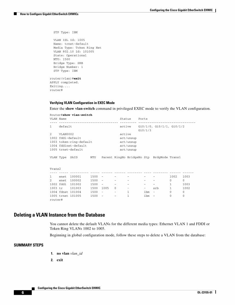
VLAN ISL Id: 1005 Name: trnet-default Media Type: Token Ring Net VLAN 802.10 Id: 101005 State: Operational MTU: 1500 Bridge Type: SRB Bridge Number: 1 STP Type: IBM
router(vlan)#exit APPLY completed. Exiting.... router#
Verifying VLAN Configuration in EXEC Mode
Enter the show vlan-switch command in privileged EXEC mode to verify the VLAN configuration.
Router#show vlan-switchVLAN Name Status Ports---- -------------------------------- --------- -------------------------------1 default active Gi0/1/0, Gi0/1/1, Gi0/1/2 Gi0/1/32 VLAN0002 active1002 fddi-default act/unsup1003 token-ring-default act/unsup1004 fddinet-default act/unsup1005 trnet-default act/unsup
VLAN Type SAID MTU Parent RingNo BridgeNo Stp BrdgMode Trans1
Trans2---- ----- ---------- ----- ------ ------ -------- ---- -------- ------ ------1 enet 100001 1500 - - - - - 1002 10032 enet 100002 1500 - - - - - 0 01002 fddi 101002 1500 - - - - - 1 10031003 tr 101003 1500 1005 0 - - srb 1 10021004 fdnet 101004 1500 - - 1 ibm - 0 01005 trnet 101005 1500 - - 1 ibm - 0 0router#
Deleting a VLAN Instance from the Database
You cannot delete the default VLANs for the different media types: Ethernet VLAN 1 and FDDI or Token Ring VLANs 1002 to 1005.
Beginning in global configuration mode, follow these steps to delete a VLAN from the database:
SUMMARY STEPS
1. no vlan vlan_id
2. exit
Configuring the Cisco Gigabit EtherSwitch EHWICHow to Configure Gigabit EtherSwitch EHWICs
7Configuring the Cisco Gigabit EtherSwitch EHWIC
OL-23155-01
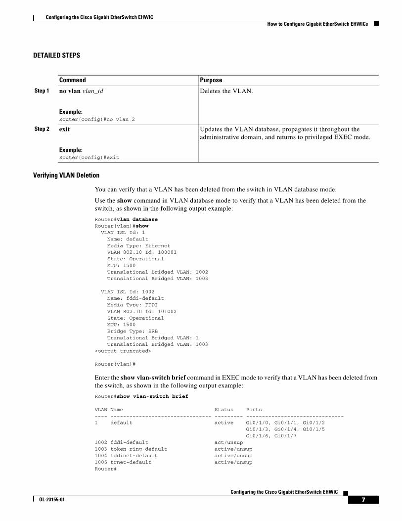
DETAILED STEPS
Verifying VLAN Deletion
You can verify that a VLAN has been deleted from the switch in VLAN database mode.
Use the show command in VLAN database mode to verify that a VLAN has been deleted from the switch, as shown in the following output example:
Router#vlan databaseRouter(vlan)#show VLAN ISL Id: 1 Name: default Media Type: Ethernet VLAN 802.10 Id: 100001 State: Operational MTU: 1500 Translational Bridged VLAN: 1002 Translational Bridged VLAN: 1003
VLAN ISL Id: 1002 Name: fddi-default Media Type: FDDI VLAN 802.10 Id: 101002 State: Operational MTU: 1500 Bridge Type: SRB Translational Bridged VLAN: 1 Translational Bridged VLAN: 1003<output truncated>
Router(vlan)#
Enter the show vlan-switch brief command in EXEC mode to verify that a VLAN has been deleted from the switch, as shown in the following output example:
Router#show vlan-switch brief
VLAN Name Status Ports---- -------------------------------- --------- -------------------------------1 default active Gi0/1/0, Gi0/1/1, Gi0/1/2 Gi0/1/3, Gi0/1/4, Gi0/1/5 Gi0/1/6, Gi0/1/71002 fddi-default act/unsup1003 token-ring-default active/unsup1004 fddinet-default active/unsup1005 trnet-default active/unsupRouter#
Command Purpose
Step 1 no vlan vlan_id
Example:Router(config)#no vlan 2
Deletes the VLAN.
Step 2 exit
Example:Router(config)#exit
Updates the VLAN database, propagates it throughout the administrative domain, and returns to privileged EXEC mode.
Configuring the Cisco Gigabit EtherSwitch EHWICHow to Configure Gigabit EtherSwitch EHWICs
8Configuring the Cisco Gigabit EtherSwitch EHWIC
OL-23155-01
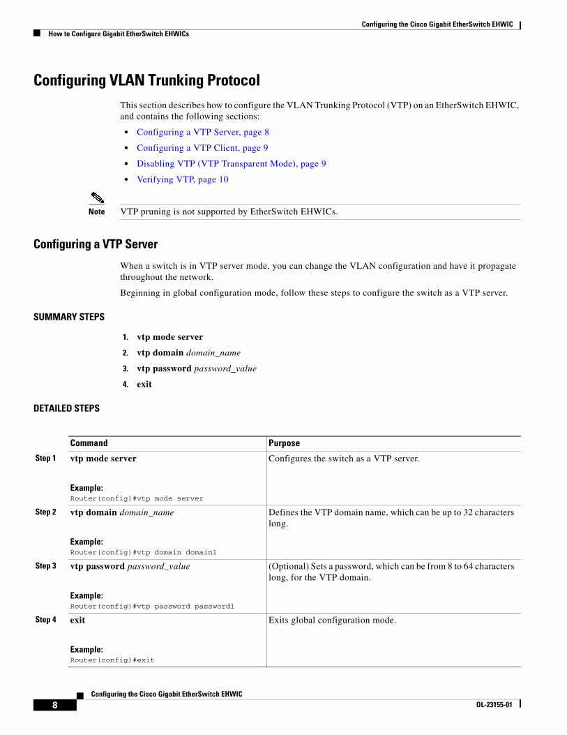
Configuring VLAN Trunking ProtocolThis section describes how to configure the VLAN Trunking Protocol (VTP) on an EtherSwitch EHWIC, and contains the following sections:
• Configuring a VTP Server, page 8
• Configuring a VTP Client, page 9
• Disabling VTP (VTP Transparent Mode), page 9
• Verifying VTP, page 10
Note VTP pruning is not supported by EtherSwitch EHWICs.
Configuring a VTP Server
When a switch is in VTP server mode, you can change the VLAN configuration and have it propagate throughout the network.
Beginning in global configuration mode, follow these steps to configure the switch as a VTP server.
SUMMARY STEPS
1. vtp mode server
2. vtp domain domain_name
3. vtp password password_value
4. exit
DETAILED STEPS
Command Purpose
Step 1 vtp mode server
Example:Router(config)#vtp mode server
Configures the switch as a VTP server.
Step 2 vtp domain domain_name
Example:Router(config)#vtp domain domain1
Defines the VTP domain name, which can be up to 32 characters long.
Step 3 vtp password password_value
Example:Router(config)#vtp password password1
(Optional) Sets a password, which can be from 8 to 64 characters long, for the VTP domain.
Step 4 exit
Example:Router(config)#exit
Exits global configuration mode.
Configuring the Cisco Gigabit EtherSwitch EHWICHow to Configure Gigabit EtherSwitch EHWICs
9Configuring the Cisco Gigabit EtherSwitch EHWIC
OL-23155-01
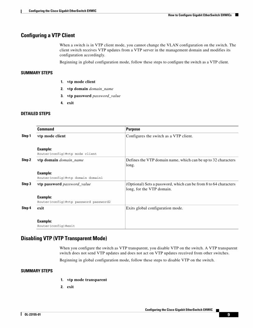
Configuring a VTP Client
When a switch is in VTP client mode, you cannot change the VLAN configuration on the switch. The client switch receives VTP updates from a VTP server in the management domain and modifies its configuration accordingly.
Beginning in global configuration mode, follow these steps to configure the switch as a VTP client.
SUMMARY STEPS
1. vtp mode client
2. vtp domain domain_name
3. vtp password password_value
4. exit
DETAILED STEPS
Disabling VTP (VTP Transparent Mode)
When you configure the switch as VTP transparent, you disable VTP on the switch. A VTP transparent switch does not send VTP updates and does not act on VTP updates received from other switches.
Beginning in global configuration mode, follow these steps to disable VTP on the switch.
SUMMARY STEPS
1. vtp mode transparent
2. exit
Command Purpose
Step 1 vtp mode client
Example:Router(config)#vtp mode client
Configures the switch as a VTP client.
Step 2 vtp domain domain_name
Example:Router(config)#vtp domain domain1
Defines the VTP domain name, which can be up to 32 characters long.
Step 3 vtp password password_value
Example:Router(config)#vtp password password2
(Optional) Sets a password, which can be from 8 to 64 characters long, for the VTP domain.
Step 4 exit
Example:Router(config)#exit
Exits global configuration mode.
Configuring the Cisco Gigabit EtherSwitch EHWICHow to Configure Gigabit EtherSwitch EHWICs
10Configuring the Cisco Gigabit EtherSwitch EHWIC
OL-23155-01
DETAILED STEPS
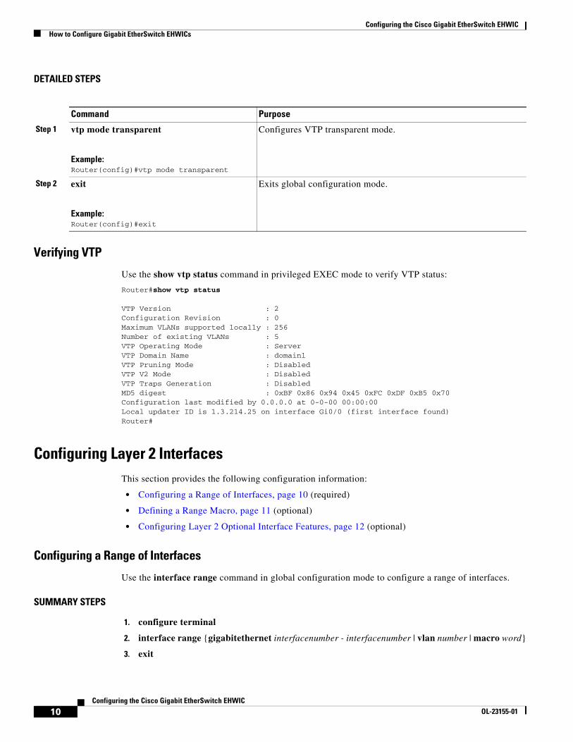
Verifying VTP
Use the show vtp status command in privileged EXEC mode to verify VTP status:
Router#show vtp status
VTP Version : 2Configuration Revision : 0Maximum VLANs supported locally : 256Number of existing VLANs : 5VTP Operating Mode : ServerVTP Domain Name : domain1VTP Pruning Mode : DisabledVTP V2 Mode : DisabledVTP Traps Generation : DisabledMD5 digest : 0xBF 0x86 0x94 0x45 0xFC 0xDF 0xB5 0x70Configuration last modified by 0.0.0.0 at 0-0-00 00:00:00Local updater ID is 1.3.214.25 on interface Gi0/0 (first interface found)Router#
Configuring Layer 2 InterfacesThis section provides the following configuration information:
• Configuring a Range of Interfaces, page 10 (required)
• Defining a Range Macro, page 11 (optional)
• Configuring Layer 2 Optional Interface Features, page 12 (optional)
Configuring a Range of Interfaces
Use the interface range command in global configuration mode to configure a range of interfaces.
SUMMARY STEPS
1. configure terminal
2. interface range {gigabitethernet interfacenumber - interfacenumber | vlan number | macro word}
3. exit
Command Purpose
Step 1 vtp mode transparent
Example:Router(config)#vtp mode transparent
Configures VTP transparent mode.
Step 2 exit
Example:Router(config)#exit
Exits global configuration mode.
Configuring the Cisco Gigabit EtherSwitch EHWICHow to Configure Gigabit EtherSwitch EHWICs
11Configuring the Cisco Gigabit EtherSwitch EHWIC
OL-23155-01
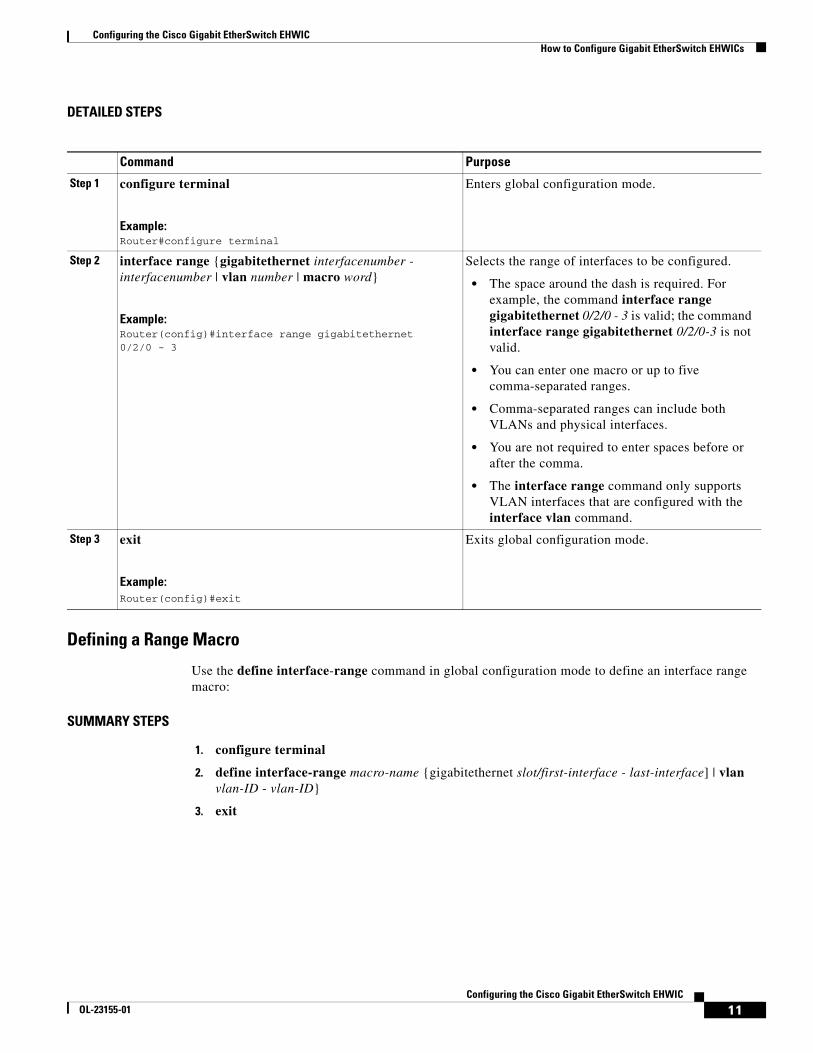
DETAILED STEPS
Defining a Range Macro
Use the define interface-range command in global configuration mode to define an interface range macro:
SUMMARY STEPS
1. configure terminal
2. define interface-range macro-name {gigabitethernet slot/first-interface - last-interface] | vlan vlan-ID - vlan-ID}
3. exit
Command Purpose
Step 1 configure terminal
Example:Router#configure terminal
Enters global configuration mode.
Step 2 interface range {gigabitethernet interfacenumber - interfacenumber | vlan number | macro word}
Example:Router(config)#interface range gigabitethernet 0/2/0 - 3
Selects the range of interfaces to be configured.
• The space around the dash is required. For example, the command interface range gigabitethernet 0/2/0 - 3 is valid; the command interface range gigabitethernet 0/2/0-3 is not valid.
• You can enter one macro or up to five comma-separated ranges.
• Comma-separated ranges can include both VLANs and physical interfaces.
• You are not required to enter spaces before or after the comma.
• The interface range command only supports VLAN interfaces that are configured with the interface vlan command.
Step 3 exit
Example:Router(config)#exit
Exits global configuration mode.
Configuring the Cisco Gigabit EtherSwitch EHWICHow to Configure Gigabit EtherSwitch EHWICs
12Configuring the Cisco Gigabit EtherSwitch EHWIC
OL-23155-01
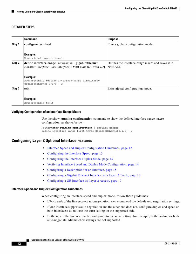
DETAILED STEPS
Verifying Configuration of an Interface Range Macro
Use the show running-configuration command to show the defined interface-range macro configuration, as shown below:
Router#show running-configuration | include definedefine interface-range first_three GigabitEthernet0/1/0 - 2
Configuring Layer 2 Optional Interface Features
• Interface Speed and Duplex Configuration Guidelines, page 12
• Configuring the Interface Speed, page 13
• Configuring the Interface Duplex Mode, page 13
• Verifying Interface Speed and Duplex Mode Configuration, page 14
• Configuring a Description for an Interface, page 15
• Configuring a Gigabit Ethernet Interface as a Layer 2 Trunk, page 15
• Configuring a GE Interface as Layer 2 Access, page 17
Interface Speed and Duplex Configuration Guidelines
When configuring an interface speed and duplex mode, follow these guidelines:
• If both ends of the line support autonegotiation, we recommend the default auto negotiation settings.
• If one interface supports auto negotiation and the other end does not, configure duplex and speed on both interfaces; do not use the auto setting on the supported side.
• Both ends of the line need to be configured to the same setting, for example, both hard-set or both auto-negotiate. Mismatched settings are not supported.
Command Purpose
Step 1 configure terminal
Example:Router#configure terminal
Enters global configuration mode.
Step 2 define interface-range macro-name {gigabitethernet slot/first-interface - last-interface] | vlan vlan-ID - vlan-ID}
Example:Router(config)#define interface-range first_three gigabitethernet 0/1/0 - 2
Defines the interface-range macro and saves it in NVRAM.
Step 3 exit
Example:Router(config)#exit
Exits global configuration mode.
Configuring the Cisco Gigabit EtherSwitch EHWICHow to Configure Gigabit EtherSwitch EHWICs
13Configuring the Cisco Gigabit EtherSwitch EHWIC
OL-23155-01
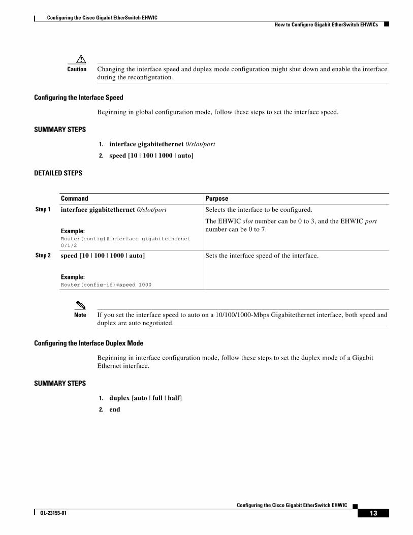
Caution Changing the interface speed and duplex mode configuration might shut down and enable the interface during the reconfiguration.
Configuring the Interface Speed
Beginning in global configuration mode, follow these steps to set the interface speed.
SUMMARY STEPS
1. interface gigabitethernet 0/slot/port
2. speed [10 | 100 | 1000 | auto]
DETAILED STEPS
Note If you set the interface speed to auto on a 10/100/1000-Mbps Gigabitethernet interface, both speed and duplex are auto negotiated.
Configuring the Interface Duplex Mode
Beginning in interface configuration mode, follow these steps to set the duplex mode of a Gigabit Ethernet interface.
SUMMARY STEPS
1. duplex [auto | full | half]
2. end
Command Purpose
Step 1 interface gigabitethernet 0/slot/port
Example:Router(config)#interface gigabitethernet 0/1/2
Selects the interface to be configured.
The EHWIC slot number can be 0 to 3, and the EHWIC port number can be 0 to 7.
Step 2 speed [10 | 100 | 1000 | auto]
Example:Router(config-if)#speed 1000
Sets the interface speed of the interface.

Configuring the Cisco Gigabit EtherSwitch EHWICHow to Configure Gigabit EtherSwitch EHWICs
14Configuring the Cisco Gigabit EtherSwitch EHWIC
OL-23155-01
DETAILED STEPS
Note If you set the port speed to auto on a 10/100/1000-Mbps Gigabit Ethernet interface, both speed and duplex are auto negotiated, and the duplex mode cannot be modified.
The following example shows how to set the interface duplex mode to auto on gigabit Ethernet interface 3:
Router(config)#interface gigabitethernet 0/1/2router(config-if)#speed 1000Router(config-if)#duplex autoRouter(config-if)#end
Verifying Interface Speed and Duplex Mode Configuration
Use the show interfaces command to verify the interface speed and duplex mode configuration for an interface, as shown in the following output example:
Router#show interfaces gigabitethernet 0/1/2
GigabitEthernet0/1/2 is up, line protocol is down Hardware is EHWIC-4 Gigabit Ethernet, address is 0022.bdd2.7915 (bia 0022.bdd2.7915) MTU 1500 bytes, BW 1000000 Kbit/sec, DLY 10 usec, reliability 255/255, txload 1/255, rxload 1/255 Encapsulation ARPA, loopback not set Keepalive set (10 sec) Auto-duplex, 1000ARP type: ARPA, ARP Timeout 04:00:00 Last input never, output never, output hang never Last clearing of "show interface" counters never Input queue: 0/75/0/0 (size/max/drops/flushes); Total output drops: 0 Queueing strategy: fifo Output queue: 0/40 (size/max) 5 minute input rate 0 bits/sec, 0 packets/sec 5 minute output rate 0 bits/sec, 0 packets/sec 0 packets input, 0 bytes, 0 no buffer Received 0 broadcasts (0 multicasts) 0 runts, 0 giants, 0 throttles 0 input errors, 0 CRC, 0 frame, 0 overrun, 0 ignored 0 watchdog, 0 multicast, 0 pause input 0 input packets with dribble condition detected 0 packets output, 0 bytes, 0 underruns 0 output errors, 0 collisions, 2 interface resets
Command Purpose
Step 1 duplex [auto | full | half]
Example:Router(config-if)#duplex auto
Sets the duplex mode of the interface.
Step 2 end
Example:Router(config-if)#end
Returns to privileged EXEC mode.
Configuring the Cisco Gigabit EtherSwitch EHWICHow to Configure Gigabit EtherSwitch EHWICs
15Configuring the Cisco Gigabit EtherSwitch EHWIC
OL-23155-01
0 unknown protocol drops 0 babbles, 0 late collision, 0 deferred 0 lost carrier, 0 no carrier, 0 pause output 0 output buffer failures, 0 output buffers swapped outRouter#
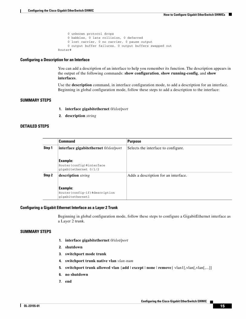
Configuring a Description for an Interface
You can add a description of an interface to help you remember its function. The description appears in the output of the following commands: show configuration, show running-config, and show interfaces.
Use the description command, in interface configuration mode, to add a description for an interface. Beginning in global configuration mode, follow these steps to add a description to the interface:
SUMMARY STEPS
1. interface gigabitethernet 0/slot/port
2. description string
DETAILED STEPS
Configuring a Gigabit Ethernet Interface as a Layer 2 Trunk
Beginning in global configuration mode, follow these steps to configure a GigabitEthernet interface as a Layer 2 trunk.
SUMMARY STEPS
1. interface gigabitethernet 0/slot/port
2. shutdown
3. switchport mode trunk
4. switchport trunk native vlan vlan-num
5. switchport trunk allowed vlan {add | except | none | remove} vlan1[,vlan[,vlan[,...]]
6. no shutdown
7. end
Command Purpose
Step 1 interface gigabitethernet 0/slot/port
Example:Router(config)#interface gigabitethernet 0/1/2
Selects the interface to configure.
Step 2 description string
Example:Router(config-if)#description gigabitethernet1
Adds a description for an interface.
Configuring the Cisco Gigabit EtherSwitch EHWICHow to Configure Gigabit EtherSwitch EHWICs
16Configuring the Cisco Gigabit EtherSwitch EHWIC
OL-23155-01
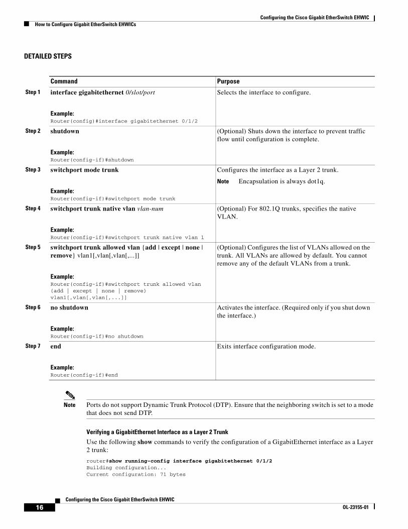
DETAILED STEPS
Note Ports do not support Dynamic Trunk Protocol (DTP). Ensure that the neighboring switch is set to a mode that does not send DTP.
Verifying a GigabitEthernet Interface as a Layer 2 Trunk
Use the following show commands to verify the configuration of a GigabitEthernet interface as a Layer 2 trunk:
router#show running-config interface gigabitethernet 0/1/2Building configuration...Current configuration: 71 bytes
Command Purpose
Step 1 interface gigabitethernet 0/slot/port
Example:Router(config)#interface gigabitethernet 0/1/2
Selects the interface to configure.
Step 2 shutdown
Example:Router(config-if)#shutdown
(Optional) Shuts down the interface to prevent traffic flow until configuration is complete.
Step 3 switchport mode trunk
Example:Router(config-if)#switchport mode trunk
Configures the interface as a Layer 2 trunk.
Note Encapsulation is always dot1q.
Step 4 switchport trunk native vlan vlan-num
Example:Router(config-if)#switchport trunk native vlan 1
(Optional) For 802.1Q trunks, specifies the native VLAN.
Step 5 switchport trunk allowed vlan {add | except | none | remove} vlan1[,vlan[,vlan[,...]]
Example:Router(config-if)#switchport trunk allowed vlan {add | except | none | remove} vlan1[,vlan[,vlan[,...]]
(Optional) Configures the list of VLANs allowed on the trunk. All VLANs are allowed by default. You cannot remove any of the default VLANs from a trunk.
Step 6 no shutdown
Example:Router(config-if)#no shutdown
Activates the interface. (Required only if you shut down the interface.)
Step 7 end
Example:Router(config-if)#end
Exits interface configuration mode.
Configuring the Cisco Gigabit EtherSwitch EHWICHow to Configure Gigabit EtherSwitch EHWICs
17Configuring the Cisco Gigabit EtherSwitch EHWIC
OL-23155-01
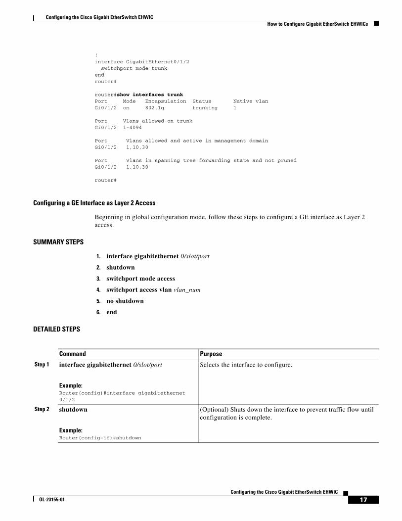
! interface GigabitEthernet0/1/2 switchport mode trunk endrouter#
router#show interfaces trunkPort Mode Encapsulation Status Native vlan Gi0/1/2 on 802.1q trunking 1
Port Vlans allowed on trunk Gi0/1/2 1-4094
Port Vlans allowed and active in management domain Gi0/1/2 1,10,30
Port Vlans in spanning tree forwarding state and not pruned Gi0/1/2 1,10,30
router#
Configuring a GE Interface as Layer 2 Access
Beginning in global configuration mode, follow these steps to configure a GE interface as Layer 2 access.
SUMMARY STEPS
1. interface gigabitethernet 0/slot/port
2. shutdown
3. switchport mode access
4. switchport access vlan vlan_num
5. no shutdown
6. end
DETAILED STEPS
Command Purpose
Step 1 interface gigabitethernet 0/slot/port
Example:Router(config)#interface gigabitethernet 0/1/2
Selects the interface to configure.
Step 2 shutdown
Example:Router(config-if)#shutdown
(Optional) Shuts down the interface to prevent traffic flow until configuration is complete.
Configuring the Cisco Gigabit EtherSwitch EHWICHow to Configure Gigabit EtherSwitch EHWICs
18Configuring the Cisco Gigabit EtherSwitch EHWIC
OL-23155-01
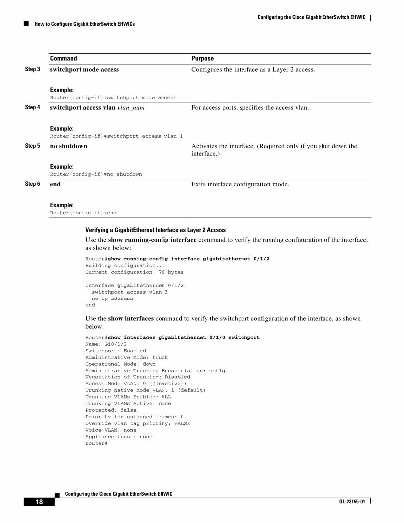
Verifying a GigabitEthernet Interface as Layer 2 Access
Use the show running-config interface command to verify the running configuration of the interface, as shown below:
Router#show running-config interface gigabitethernet 0/1/2Building configuration...Current configuration: 76 bytes ! interface gigabitethernet 0/1/2 switchport access vlan 3 no ip address end
Use the show interfaces command to verify the switchport configuration of the interface, as shown below:
Router#show interfaces gigabitethernet 0/1/0 switchportName: Gi0/1/2Switchport: EnabledAdministrative Mode: trunkOperational Mode: downAdministrative Trunking Encapsulation: dot1qNegotiation of Trunking: DisabledAccess Mode VLAN: 0 ((Inactive))Trunking Native Mode VLAN: 1 (default)Trunking VLANs Enabled: ALLTrunking VLANs Active: noneProtected: falsePriority for untagged frames: 0Override vlan tag priority: FALSEVoice VLAN: noneAppliance trust: nonerouter#
Step 3 switchport mode access
Example:Router(config-if)#switchport mode access
Configures the interface as a Layer 2 access.
Step 4 switchport access vlan vlan_num
Example:Router(config-if)#switchport access vlan 1
For access ports, specifies the access vlan.
Step 5 no shutdown
Example:Router(config-if)#no shutdown
Activates the interface. (Required only if you shut down the interface.)
Step 6 end
Example:Router(config-if)#end
Exits interface configuration mode.
Command Purpose
Configuring the Cisco Gigabit EtherSwitch EHWICHow to Configure Gigabit EtherSwitch EHWICs
19Configuring the Cisco Gigabit EtherSwitch EHWIC
OL-23155-01
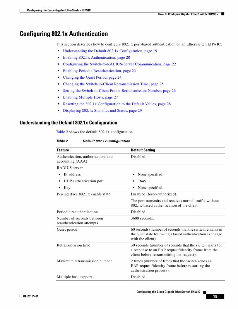
Configuring 802.1x AuthenticationThis section describes how to configure 802.1x port-based authentication on an EtherSwitch EHWIC:
• Understanding the Default 802.1x Configuration, page 19
• Enabling 802.1x Authentication, page 20
• Configuring the Switch-to-RADIUS-Server Communication, page 22
• Enabling Periodic Reauthentication, page 23
• Changing the Quiet Period, page 24
• Changing the Switch-to-Client Retransmission Time, page 25
• Setting the Switch-to-Client Frame-Retransmission Number, page 26
• Enabling Multiple Hosts, page 27
• Resetting the 802.1x Configuration to the Default Values, page 28
• Displaying 802.1x Statistics and Status, page 29
Understanding the Default 802.1x Configuration
Table 2 shows the default 802.1x configuration.
Table 2 Default 802.1x Configuration
Feature Default Setting
Authentication, authorization, and accounting (AAA)
Disabled.
RADIUS server
• IP address
• UDP authentication port
• Key
• None specified
• 1645
• None specified
Per-interface 802.1x enable state Disabled (force-authorized).
The port transmits and receives normal traffic without 802.1x-based authentication of the client.
Periodic reauthentication Disabled.
Number of seconds between reauthentication attempts
3600 seconds.
Quiet period 60 seconds (number of seconds that the switch remains in the quiet state following a failed authentication exchange with the client).
Retransmission time 30 seconds (number of seconds that the switch waits for a response to an EAP request/identity frame from the client before retransmitting the request).
Maximum retransmission number 2 times (number of times that the switch sends an EAP-request/identity frame before restarting the authentication process).
Multiple host support Disabled.
Configuring the Cisco Gigabit EtherSwitch EHWICHow to Configure Gigabit EtherSwitch EHWICs
20Configuring the Cisco Gigabit EtherSwitch EHWIC
OL-23155-01
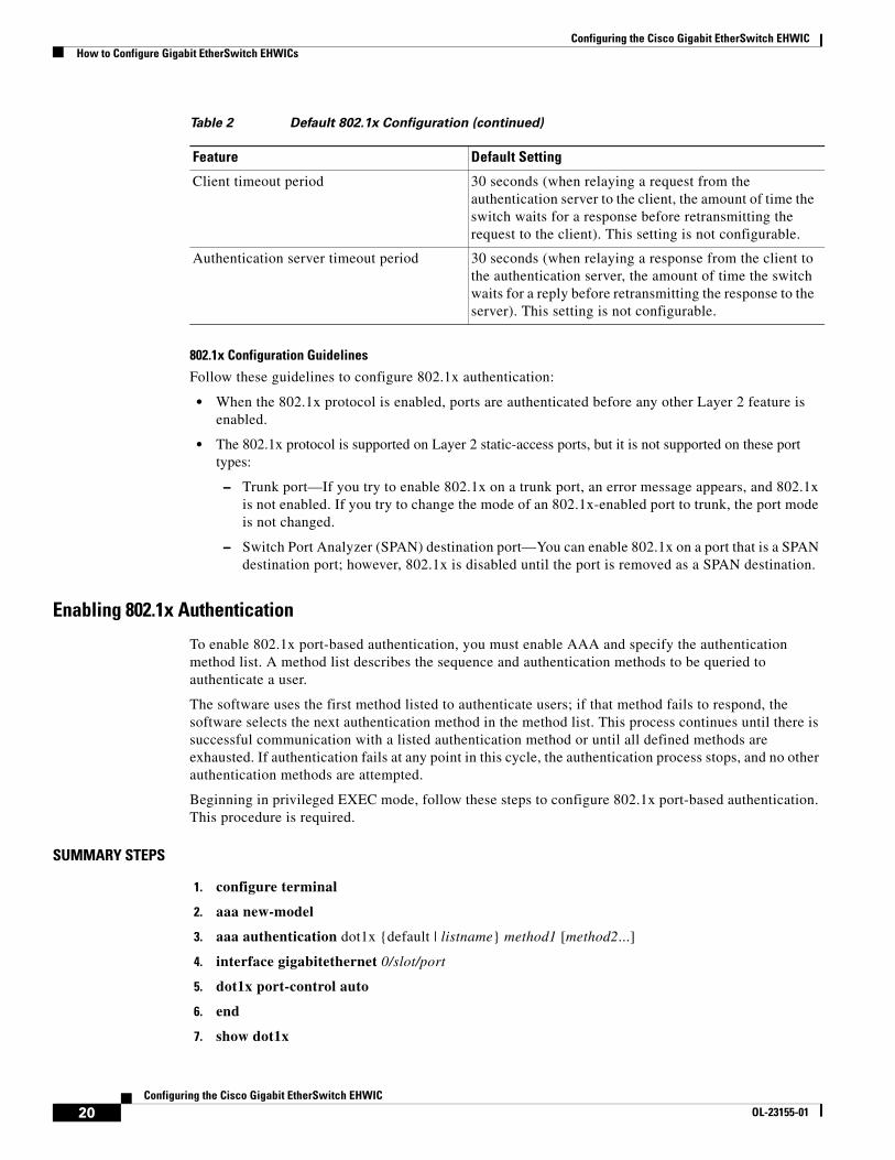
802.1x Configuration Guidelines
Follow these guidelines to configure 802.1x authentication:
• When the 802.1x protocol is enabled, ports are authenticated before any other Layer 2 feature is enabled.
• The 802.1x protocol is supported on Layer 2 static-access ports, but it is not supported on these port types:
– Trunk port—If you try to enable 802.1x on a trunk port, an error message appears, and 802.1x is not enabled. If you try to change the mode of an 802.1x-enabled port to trunk, the port mode is not changed.
– Switch Port Analyzer (SPAN) destination port—You can enable 802.1x on a port that is a SPAN destination port; however, 802.1x is disabled until the port is removed as a SPAN destination.
Enabling 802.1x Authentication
To enable 802.1x port-based authentication, you must enable AAA and specify the authentication method list. A method list describes the sequence and authentication methods to be queried to authenticate a user.
The software uses the first method listed to authenticate users; if that method fails to respond, the software selects the next authentication method in the method list. This process continues until there is successful communication with a listed authentication method or until all defined methods are exhausted. If authentication fails at any point in this cycle, the authentication process stops, and no other authentication methods are attempted.
Beginning in privileged EXEC mode, follow these steps to configure 802.1x port-based authentication. This procedure is required.
SUMMARY STEPS
1. configure terminal
2. aaa new-model
3. aaa authentication dot1x {default | listname} method1 [method2...]
4. interface gigabitethernet 0/slot/port
5. dot1x port-control auto
6. end
7. show dot1x
Client timeout period 30 seconds (when relaying a request from the authentication server to the client, the amount of time the switch waits for a response before retransmitting the request to the client). This setting is not configurable.
Authentication server timeout period 30 seconds (when relaying a response from the client to the authentication server, the amount of time the switch waits for a reply before retransmitting the response to the server). This setting is not configurable.
Table 2 Default 802.1x Configuration (continued)
Feature Default Setting
Configuring the Cisco Gigabit EtherSwitch EHWICHow to Configure Gigabit EtherSwitch EHWICs
21Configuring the Cisco Gigabit EtherSwitch EHWIC
OL-23155-01
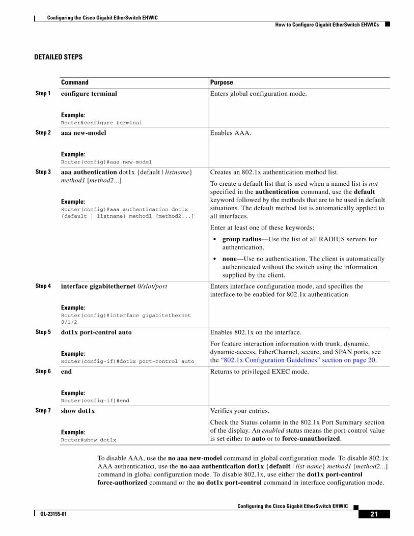
DETAILED STEPS
To disable AAA, use the no aaa new-model command in global configuration mode. To disable 802.1x AAA authentication, use the no aaa authentication dot1x {default | list-name} method1 [method2...] command in global configuration mode. To disable 802.1x, use either the dot1x port-control force-authorized command or the no dot1x port-control command in interface configuration mode.
Command Purpose
Step 1 configure terminal
Example:Router#configure terminal
Enters global configuration mode.
Step 2 aaa new-model
Example:Router(config)#aaa new-model
Enables AAA.
Step 3 aaa authentication dot1x {default | listname} method1 [method2...]
Example:Router(config)#aaa authentication dot1x {default | listname} method1 [method2...]
Creates an 802.1x authentication method list.
To create a default list that is used when a named list is not specified in the authentication command, use the default keyword followed by the methods that are to be used in default situations. The default method list is automatically applied to all interfaces.
Enter at least one of these keywords:
• group radius—Use the list of all RADIUS servers for authentication.
• none—Use no authentication. The client is automatically authenticated without the switch using the information supplied by the client.
Step 4 interface gigabitethernet 0/slot/port
Example:Router(config)#interface gigabitethernet 0/1/2
Enters interface configuration mode, and specifies the interface to be enabled for 802.1x authentication.
Step 5 dot1x port-control auto
Example:Router(config-if)#dot1x port-control auto
Enables 802.1x on the interface.
For feature interaction information with trunk, dynamic, dynamic-access, EtherChannel, secure, and SPAN ports, see the “802.1x Configuration Guidelines” section on page 20.
Step 6 end
Example:Router(config-if)#end
Returns to privileged EXEC mode.
Step 7 show dot1x
Example:Router#show dot1x
Verifies your entries.
Check the Status column in the 802.1x Port Summary section of the display. An enabled status means the port-control value is set either to auto or to force-unauthorized.
Configuring the Cisco Gigabit EtherSwitch EHWICHow to Configure Gigabit EtherSwitch EHWICs
22Configuring the Cisco Gigabit EtherSwitch EHWIC
OL-23155-01
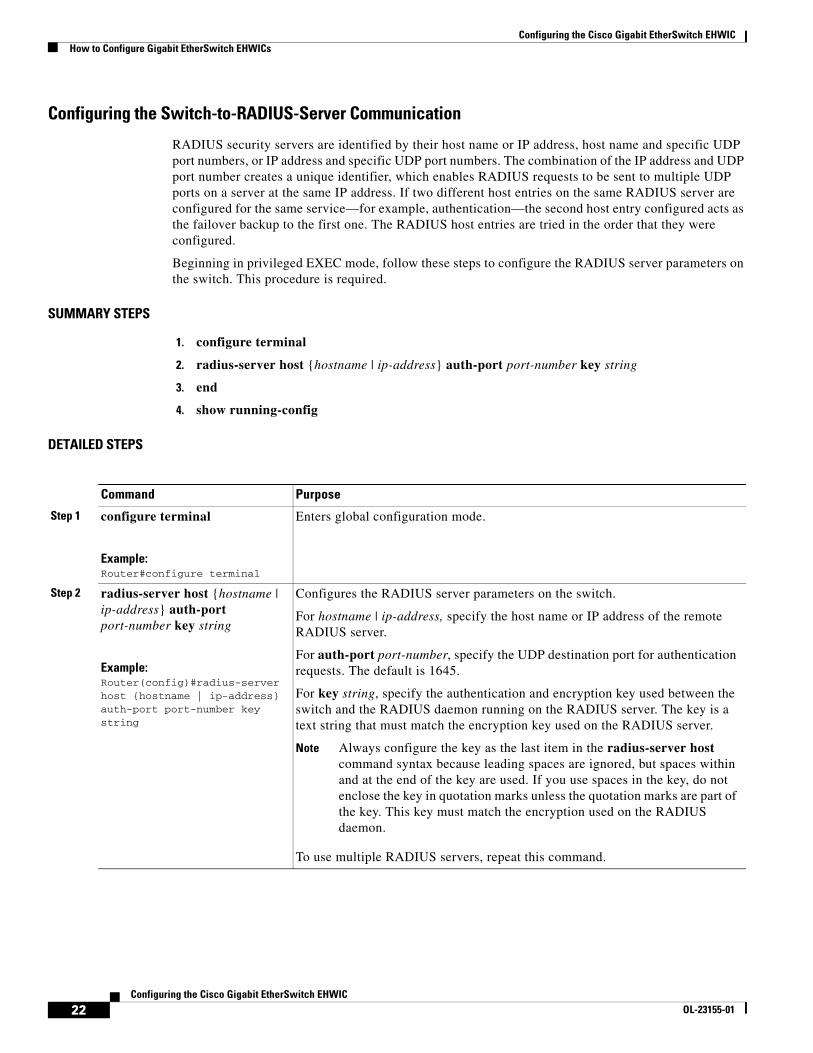
Configuring the Switch-to-RADIUS-Server Communication
RADIUS security servers are identified by their host name or IP address, host name and specific UDP port numbers, or IP address and specific UDP port numbers. The combination of the IP address and UDP port number creates a unique identifier, which enables RADIUS requests to be sent to multiple UDP ports on a server at the same IP address. If two different host entries on the same RADIUS server are configured for the same service—for example, authentication—the second host entry configured acts as the failover backup to the first one. The RADIUS host entries are tried in the order that they were configured.
Beginning in privileged EXEC mode, follow these steps to configure the RADIUS server parameters on the switch. This procedure is required.
SUMMARY STEPS
1. configure terminal
2. radius-server host {hostname | ip-address} auth-port port-number key string
3. end
4. show running-config
DETAILED STEPS
Command Purpose
Step 1 configure terminal
Example:Router#configure terminal
Enters global configuration mode.
Step 2 radius-server host {hostname | ip-address} auth-port port-number key string
Example:Router(config)#radius-server host {hostname | ip-address} auth-port port-number key string
Configures the RADIUS server parameters on the switch.
For hostname | ip-address, specify the host name or IP address of the remote RADIUS server.
For auth-port port-number, specify the UDP destination port for authentication requests. The default is 1645.
For key string, specify the authentication and encryption key used between the switch and the RADIUS daemon running on the RADIUS server. The key is a text string that must match the encryption key used on the RADIUS server.
Note Always configure the key as the last item in the radius-server host command syntax because leading spaces are ignored, but spaces within and at the end of the key are used. If you use spaces in the key, do not enclose the key in quotation marks unless the quotation marks are part of the key. This key must match the encryption used on the RADIUS daemon.
To use multiple RADIUS servers, repeat this command.
Configuring the Cisco Gigabit EtherSwitch EHWICHow to Configure Gigabit EtherSwitch EHWICs
23Configuring the Cisco Gigabit EtherSwitch EHWIC
OL-23155-01
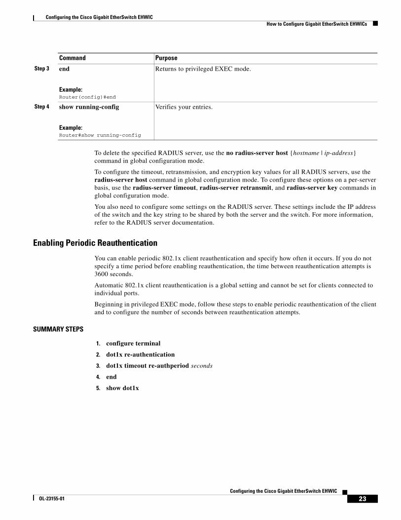
To delete the specified RADIUS server, use the no radius-server host {hostname | ip-address} command in global configuration mode.
To configure the timeout, retransmission, and encryption key values for all RADIUS servers, use the radius-server host command in global configuration mode. To configure these options on a per-server basis, use the radius-server timeout, radius-server retransmit, and radius-server key commands in global configuration mode.
You also need to configure some settings on the RADIUS server. These settings include the IP address of the switch and the key string to be shared by both the server and the switch. For more information, refer to the RADIUS server documentation.
Enabling Periodic Reauthentication
You can enable periodic 802.1x client reauthentication and specify how often it occurs. If you do not specify a time period before enabling reauthentication, the time between reauthentication attempts is 3600 seconds.
Automatic 802.1x client reauthentication is a global setting and cannot be set for clients connected to individual ports.
Beginning in privileged EXEC mode, follow these steps to enable periodic reauthentication of the client and to configure the number of seconds between reauthentication attempts.
SUMMARY STEPS
1. configure terminal
2. dot1x re-authentication
3. dot1x timeout re-authperiod seconds
4. end
5. show dot1x
Step 3 end
Example:Router(config)#end
Returns to privileged EXEC mode.
Step 4 show running-config
Example:Router#show running-config
Verifies your entries.
Command Purpose
Configuring the Cisco Gigabit EtherSwitch EHWICHow to Configure Gigabit EtherSwitch EHWICs
24Configuring the Cisco Gigabit EtherSwitch EHWIC
OL-23155-01
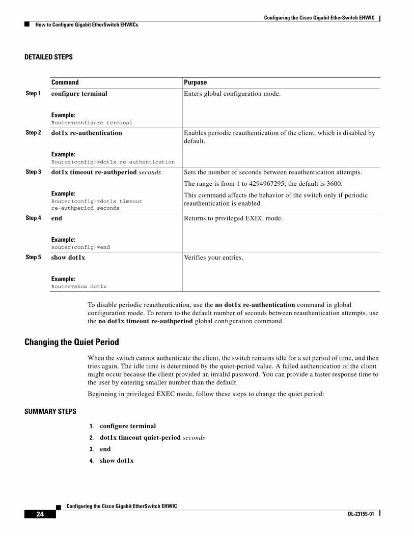
DETAILED STEPS
To disable periodic reauthentication, use the no dot1x re-authentication command in global configuration mode. To return to the default number of seconds between reauthentication attempts, use the no dot1x timeout re-authperiod global configuration command.
Changing the Quiet Period
When the switch cannot authenticate the client, the switch remains idle for a set period of time, and then tries again. The idle time is determined by the quiet-period value. A failed authentication of the client might occur because the client provided an invalid password. You can provide a faster response time to the user by entering smaller number than the default.
Beginning in privileged EXEC mode, follow these steps to change the quiet period:
SUMMARY STEPS
1. configure terminal
2. dot1x timeout quiet-period seconds
3. end
4. show dot1x
Command Purpose
Step 1 configure terminal
Example:Router#configure terminal
Enters global configuration mode.
Step 2 dot1x re-authentication
Example:Router(config)#dot1x re-authentication
Enables periodic reauthentication of the client, which is disabled by default.
Step 3 dot1x timeout re-authperiod seconds
Example:Router(config)#dot1x timeout re-authperiod seconds
Sets the number of seconds between reauthentication attempts.
The range is from 1 to 4294967295; the default is 3600.
This command affects the behavior of the switch only if periodic reauthentication is enabled.
Step 4 end
Example:Router(config)#end
Returns to privileged EXEC mode.
Step 5 show dot1x
Example:Router#show dot1x
Verifies your entries.
Configuring the Cisco Gigabit EtherSwitch EHWICHow to Configure Gigabit EtherSwitch EHWICs
25Configuring the Cisco Gigabit EtherSwitch EHWIC
OL-23155-01
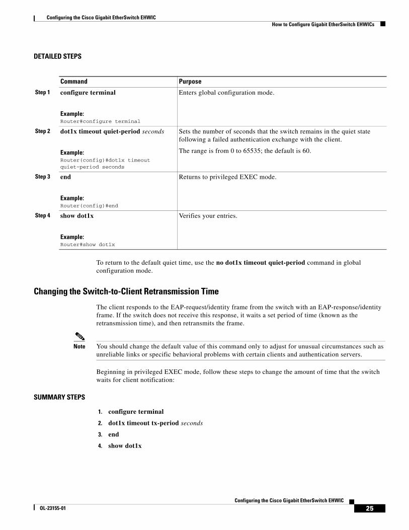
DETAILED STEPS
To return to the default quiet time, use the no dot1x timeout quiet-period command in global configuration mode.
Changing the Switch-to-Client Retransmission Time
The client responds to the EAP-request/identity frame from the switch with an EAP-response/identity frame. If the switch does not receive this response, it waits a set period of time (known as the retransmission time), and then retransmits the frame.
Note You should change the default value of this command only to adjust for unusual circumstances such as unreliable links or specific behavioral problems with certain clients and authentication servers.
Beginning in privileged EXEC mode, follow these steps to change the amount of time that the switch waits for client notification:
SUMMARY STEPS
1. configure terminal
2. dot1x timeout tx-period seconds
3. end
4. show dot1x
Command Purpose
Step 1 configure terminal
Example:Router#configure terminal
Enters global configuration mode.
Step 2 dot1x timeout quiet-period seconds
Example:Router(config)#dot1x timeout quiet-period seconds
Sets the number of seconds that the switch remains in the quiet state following a failed authentication exchange with the client.
The range is from 0 to 65535; the default is 60.
Step 3 end
Example:Router(config)#end
Returns to privileged EXEC mode.
Step 4 show dot1x
Example:Router#show dot1x
Verifies your entries.
Configuring the Cisco Gigabit EtherSwitch EHWICHow to Configure Gigabit EtherSwitch EHWICs
26Configuring the Cisco Gigabit EtherSwitch EHWIC
OL-23155-01
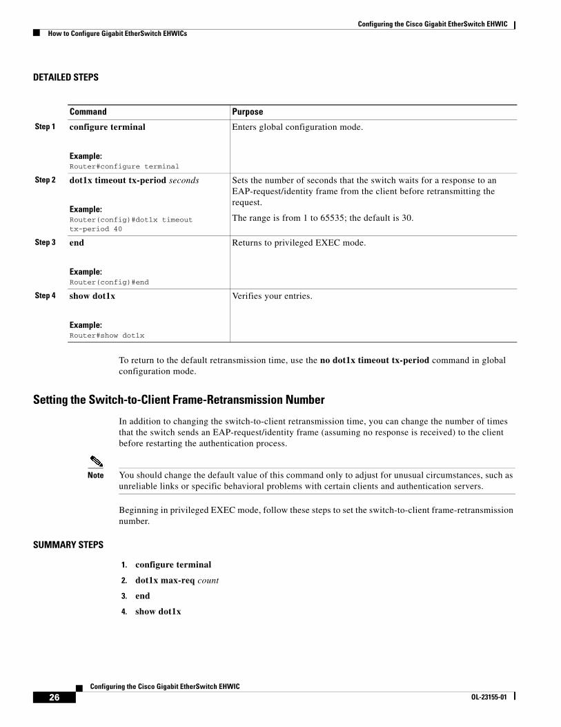
DETAILED STEPS
To return to the default retransmission time, use the no dot1x timeout tx-period command in global configuration mode.
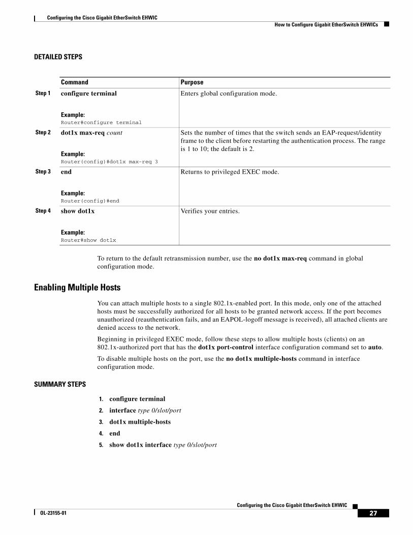
Setting the Switch-to-Client Frame-Retransmission Number
In addition to changing the switch-to-client retransmission time, you can change the number of times that the switch sends an EAP-request/identity frame (assuming no response is received) to the client before restarting the authentication process.
Note You should change the default value of this command only to adjust for unusual circumstances, such as unreliable links or specific behavioral problems with certain clients and authentication servers.
Beginning in privileged EXEC mode, follow these steps to set the switch-to-client frame-retransmission number.
SUMMARY STEPS
1. configure terminal
2. dot1x max-req count
3. end
4. show dot1x
Command Purpose
Step 1 configure terminal
Example:Router#configure terminal
Enters global configuration mode.
Step 2 dot1x timeout tx-period seconds
Example:Router(config)#dot1x timeout tx-period 40
Sets the number of seconds that the switch waits for a response to an EAP-request/identity frame from the client before retransmitting the request.
The range is from 1 to 65535; the default is 30.
Step 3 end
Example:Router(config)#end
Returns to privileged EXEC mode.
Step 4 show dot1x
Example:Router#show dot1x
Verifies your entries.
Configuring the Cisco Gigabit EtherSwitch EHWICHow to Configure Gigabit EtherSwitch EHWICs
27Configuring the Cisco Gigabit EtherSwitch EHWIC
OL-23155-01
DETAILED STEPS
To return to the default retransmission number, use the no dot1x max-req command in global configuration mode.
Enabling Multiple Hosts
You can attach multiple hosts to a single 802.1x-enabled port. In this mode, only one of the attached hosts must be successfully authorized for all hosts to be granted network access. If the port becomes unauthorized (reauthentication fails, and an EAPOL-logoff message is received), all attached clients are denied access to the network.
Beginning in privileged EXEC mode, follow these steps to allow multiple hosts (clients) on an 802.1x-authorized port that has the dot1x port-control interface configuration command set to auto.
To disable multiple hosts on the port, use the no dot1x multiple-hosts command in interface configuration mode.
SUMMARY STEPS
1. configure terminal
2. interface type 0/slot/port
3. dot1x multiple-hosts
4. end
5. show dot1x interface type 0/slot/port
Command Purpose
Step 1 configure terminal
Example:Router#configure terminal
Enters global configuration mode.
Step 2 dot1x max-req count
Example:Router(config)#dot1x max-req 3
Sets the number of times that the switch sends an EAP-request/identity frame to the client before restarting the authentication process. The range is 1 to 10; the default is 2.
Step 3 end
Example:Router(config)#end
Returns to privileged EXEC mode.
Step 4 show dot1x
Example:Router#show dot1x
Verifies your entries.

Configuring the Cisco Gigabit EtherSwitch EHWICHow to Configure Gigabit EtherSwitch EHWICs
28Configuring the Cisco Gigabit EtherSwitch EHWIC
OL-23155-01
DETAILED STEPS
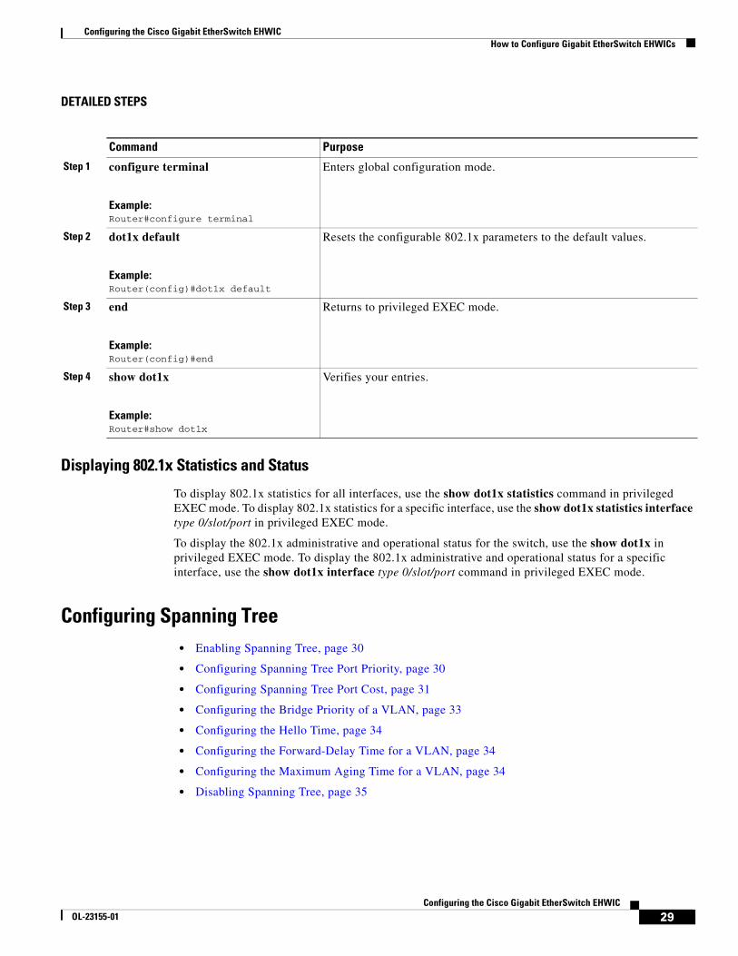
Resetting the 802.1x Configuration to the Default Values
You can reset the 802.1x configuration to the default values with a single command.
Beginning in privileged EXEC mode, follow these steps to reset the 802.1x configuration to the default values.
SUMMARY STEPS
1. configure terminal
2. dot1x default
3. end
4. show dot1x
Command Purpose
Step 1 configure terminal
Example:Router#configure terminal
Enters global configuration mode.
Step 2 interface gigabitethernet 0/slot/port
Example:Router(config)#interface gigabitethernet 0/1/2
Enters interface configuration mode, and specify the interface to which multiple hosts are indirectly attached.
Step 3 dot1x multiple-hosts
Example:Router(config-if)#dot1x multiple-hosts
Allows multiple hosts (clients) on an 802.1x-authorized port.
Make sure that the dot1x port-control interface configuration command is set to auto for the specified interface.
Step 4 end
Example:Router(config-if)#end
Returns to privileged EXEC mode.
Step 5 show dot1x interface type 0/slot/por
Example:Router#show dot1x interface type 0/1/2
Verifies your entries.
Configuring the Cisco Gigabit EtherSwitch EHWICHow to Configure Gigabit EtherSwitch EHWICs
29Configuring the Cisco Gigabit EtherSwitch EHWIC
OL-23155-01
DETAILED STEPS
Displaying 802.1x Statistics and Status
To display 802.1x statistics for all interfaces, use the show dot1x statistics command in privileged EXEC mode. To display 802.1x statistics for a specific interface, use the show dot1x statistics interface type 0/slot/port in privileged EXEC mode.
To display the 802.1x administrative and operational status for the switch, use the show dot1x in privileged EXEC mode. To display the 802.1x administrative and operational status for a specific interface, use the show dot1x interface type 0/slot/port command in privileged EXEC mode.
Configuring Spanning Tree• Enabling Spanning Tree, page 30
• Configuring Spanning Tree Port Priority, page 30
• Configuring Spanning Tree Port Cost, page 31
• Configuring the Bridge Priority of a VLAN, page 33
• Configuring the Hello Time, page 34
• Configuring the Forward-Delay Time for a VLAN, page 34
• Configuring the Maximum Aging Time for a VLAN, page 34
• Disabling Spanning Tree, page 35
Command Purpose
Step 1 configure terminal
Example:Router#configure terminal
Enters global configuration mode.
Step 2 dot1x default
Example:Router(config)#dot1x default
Resets the configurable 802.1x parameters to the default values.
Step 3 end
Example:Router(config)#end
Returns to privileged EXEC mode.
Step 4 show dot1x
Example:Router#show dot1x
Verifies your entries.
Configuring the Cisco Gigabit EtherSwitch EHWICHow to Configure Gigabit EtherSwitch EHWICs
30Configuring the Cisco Gigabit EtherSwitch EHWIC
OL-23155-01
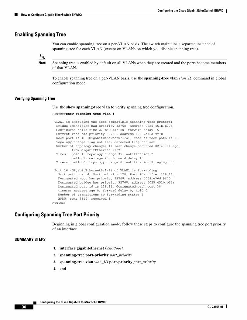
Enabling Spanning Tree
You can enable spanning tree on a per-VLAN basis. The switch maintains a separate instance of spanning tree for each VLAN (except on VLANs on which you disable spanning tree).
Note Spanning tree is enabled by default on all VLANs when they are created and the ports become members of that VLAN.
To enable spanning tree on a per-VLAN basis, use the spanning-tree vlan vlan_ID command in global configuration mode.
Verifying Spanning Tree
Use the show spanning-tree vlan to verify spanning tree configuration.
Router#show spanning-tree vlan 1
VLAN1 is executing the ieee compatible Spanning Tree protocol Bridge Identifier has priority 32768, address 0025.451b.b22a Configured hello time 2, max age 20, forward delay 15 Current root has priority 32768, address 0008.e36d.9f70 Root port is 18 (GigabitEthernet0/1/4), cost of root path is 38 Topology change flag not set, detected flag not set Number of topology changes 11 last change occurred 02:43:01 ago from GigabitEthernet0/1/2 Times: hold 1, topology change 35, notification 2 hello 2, max age 20, forward delay 15 Timers: hello 0, topology change 0, notification 0, aging 300
Port 16 (GigabitEthernet0/1/2) of VLAN1 is forwarding Port path cost 4, Port priority 128, Port Identifier 128.16. Designated root has priority 32768, address 0008.e36d.9f70 Designated bridge has priority 32768, address 0025.451b.b22a Designated port id is 128.16, designated path cost 38 Timers: message age 0, forward delay 0, hold 0 Number of transitions to forwarding state: 1 BPDU: sent 9810, received 1 Router#
Configuring Spanning Tree Port Priority
Beginning in global configuration mode, follow these steps to configure the spanning tree port priority of an interface.
SUMMARY STEPS
1. interface gigabitethernet 0/slot/port
2. spanning-tree port-priority port_priority
3. spanning-tree vlan vlan_ID port-priority port_priority
4. end
Configuring the Cisco Gigabit EtherSwitch EHWICHow to Configure Gigabit EtherSwitch EHWICs
31Configuring the Cisco Gigabit EtherSwitch EHWIC
OL-23155-01
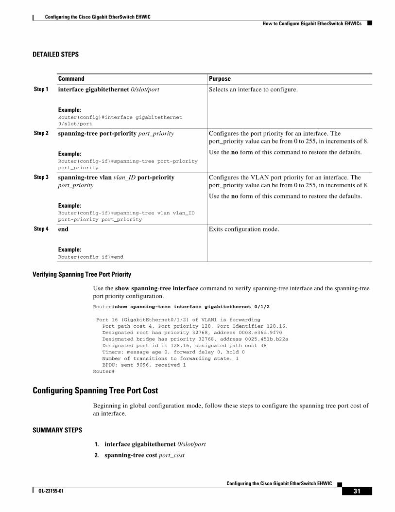
DETAILED STEPS
Verifying Spanning Tree Port Priority
Use the show spanning-tree interface command to verify spanning-tree interface and the spanning-tree port priority configuration.
Router#show spanning-tree interface gigabitethernet 0/1/2
Port 16 (GigabitEthernet0/1/2) of VLAN1 is forwarding Port path cost 4, Port priority 128, Port Identifier 128.16. Designated root has priority 32768, address 0008.e36d.9f70 Designated bridge has priority 32768, address 0025.451b.b22a Designated port id is 128.16, designated path cost 38 Timers: message age 0, forward delay 0, hold 0 Number of transitions to forwarding state: 1 BPDU: sent 9096, received 1Router#
Configuring Spanning Tree Port Cost
Beginning in global configuration mode, follow these steps to configure the spanning tree port cost of an interface.
SUMMARY STEPS
1. interface gigabitethernet 0/slot/port
2. spanning-tree cost port_cost
Command Purpose
Step 1 interface gigabitethernet 0/slot/port
Example:Router(config)#interface gigabitethernet 0/slot/port
Selects an interface to configure.
Step 2 spanning-tree port-priority port_priority
Example:Router(config-if)#spanning-tree port-priority port_priority
Configures the port priority for an interface. The port_priority value can be from 0 to 255, in increments of 8.
Use the no form of this command to restore the defaults.
Step 3 spanning-tree vlan vlan_ID port-priority port_priority
Example:Router(config-if)#spanning-tree vlan vlan_ID port-priority port_priority
Configures the VLAN port priority for an interface. The port_priority value can be from 0 to 255, in increments of 8.
Use the no form of this command to restore the defaults.
Step 4 end
Example:Router(config-if)#end
Exits configuration mode.
Configuring the Cisco Gigabit EtherSwitch EHWICHow to Configure Gigabit EtherSwitch EHWICs
32Configuring the Cisco Gigabit EtherSwitch EHWIC
OL-23155-01
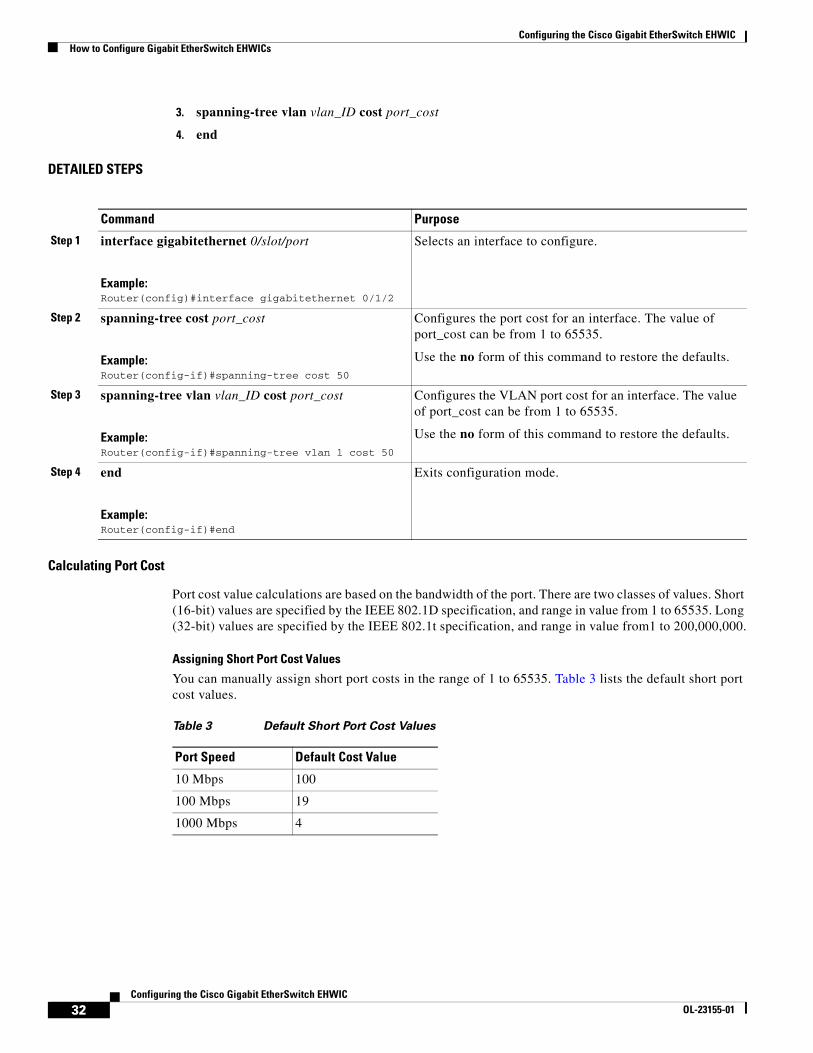
3. spanning-tree vlan vlan_ID cost port_cost
4. end
DETAILED STEPS
Calculating Port Cost
Port cost value calculations are based on the bandwidth of the port. There are two classes of values. Short (16-bit) values are specified by the IEEE 802.1D specification, and range in value from 1 to 65535. Long (32-bit) values are specified by the IEEE 802.1t specification, and range in value from1 to 200,000,000.
Assigning Short Port Cost Values
You can manually assign short port costs in the range of 1 to 65535. Table 3 lists the default short port cost values.
Command Purpose
Step 1 interface gigabitethernet 0/slot/port
Example:Router(config)#interface gigabitethernet 0/1/2
Selects an interface to configure.
Step 2 spanning-tree cost port_cost
Example:Router(config-if)#spanning-tree cost 50
Configures the port cost for an interface. The value of port_cost can be from 1 to 65535.
Use the no form of this command to restore the defaults.
Step 3 spanning-tree vlan vlan_ID cost port_cost
Example:Router(config-if)#spanning-tree vlan 1 cost 50
Configures the VLAN port cost for an interface. The value of port_cost can be from 1 to 65535.
Use the no form of this command to restore the defaults.
Step 4 end
Example:Router(config-if)#end
Exits configuration mode.
Table 3 Default Short Port Cost Values
Port Speed Default Cost Value
10 Mbps 100
100 Mbps 19
1000 Mbps 4

Configuring the Cisco Gigabit EtherSwitch EHWICHow to Configure Gigabit EtherSwitch EHWICs
33Configuring the Cisco Gigabit EtherSwitch EHWIC
OL-23155-01
Assigning Long Port Cost Values
You can manually assign long port costs in the range of 1 to 200,000,000. Table 4 lists the recommended cost values.
Verifying Spanning Tree Port Cost
Use the show spanning-tree vlan command to verify the spanning-tree port cost configuration.
Router#show spanning-tree vlan 200
Port 264 (GigabitEthernet0/1/2) of VLAN200 is forwardingPort path cost 17, Port priority 64, Port Identifier 129.8. Designated root has priority 32768, address 0010.0d40.34c7 Designated bridge has priority 32768, address 0010.0d40.34c7 Designated port id is 128.1, designated path cost 0 Timers: message age 2, forward delay 0, hold 0 Number of transitions to forwarding state: 1 BPDU: sent 0, received 13513Router#
Configuring the Bridge Priority of a VLAN
To configure the spanning tree bridge priority of a VLAN, use the spanning-tree vlan vlan_ID priority bridge_priority command in global configuration mode. The bridge_priority value can be from 1 to 65535.
Use the no form of this command to restore the defaults.
Router(config)#spanning-tree vlan 1 priority 25
Caution Exercise care when using this command. For most situations, the spanning-tree vlan vlan_ID root primary command and the spanning-tree vlan vlan_ID root secondary command are the preferred commands to modify the bridge priority.
Verifying the Bridge Priority of a VLAN
Use the show spanning-tree vlan bridge command to verify the bridge priority, as illustrated below:
Router#show spanning-tree vlan 200 bridge brief Hello Max FwdVlan Bridge ID Time Age Delay Protocol---------------- -------------------- ---- ---- ----- --------VLAN200 33792 0050.3e8d.64c8 2 20 15 ieeeRouter#
Table 4 Recommended Long Port Cost Values
Port Speed Recommended Value Recommended Range
10 Mbps 2,000,000 200,000 to 20,000,000
100 Mbps 200,000 20,000 to 2,000,000
1000 Mbps 20,000 2,000 to 200,000
Configuring the Cisco Gigabit EtherSwitch EHWICHow to Configure Gigabit EtherSwitch EHWICs
34Configuring the Cisco Gigabit EtherSwitch EHWIC
OL-23155-01
Configuring the Hello Time
To configure the hello interval for the spanning tree, use the spanning-tree vlan vlan_ID hello-time hello_time command in global configuration mode. The hello_time value can be from 1 to 10 seconds. Use the no form of this command to restore the defaults.
Router(config)#spanning-tree vlan 1 hello-time 5
Configuring the Forward-Delay Time for a VLAN
To configure the forward delay for the spanning tree, use the spanning-tree vlan vlan_ID forward-time forward_time command in global configuration mode. The value of forward_time can be from 4 to 30 seconds. Use the no form of this command to restore the defaults.
Router(config)#spanning-tree vlan 1 forward-time 4
Configuring the Maximum Aging Time for a VLAN
To configure the maximum age interval for the spanning tree, use the spanning-tree vlan vlan_ID max-age max_age command in global configuration mode. The value of max_age can be from 6 to 40 seconds. Use the no form of this command to restore the defaults.
Router(config)#spanning-tree vlan 1 max-age 20
Configuring the Root Bridge
The EtherSwitch EHWIC maintains a separate instance of spanning tree for each active VLAN configured on the switch. A bridge ID, consisting of the bridge priority and the bridge MAC address, is associated with each instance. For each VLAN, the switch with the lowest bridge ID becomes the root bridge for that VLAN.
To configure a VLAN instance to become the root bridge, the bridge priority can be modified from the default value (32768) to a significantly lower value so that the bridge becomes the root bridge for the specified VLAN. Use the spanning-tree vlan vlan-ID root command to alter the bridge priority.
The switch checks the bridge priority of the current root bridges for each VLAN. The bridge priority for the specified VLANs is set to 8192 if this value will cause the switch to become the root for the specified VLANs.
If any root switch for the specified VLANs has a bridge priority lower than 8192, the switch sets the bridge priority for the specified VLANs to 1 less than the lowest bridge priority.
For example, if all switches in the network have the bridge priority for VLAN 100 set to the default value of 32768, entering the spanning-tree vlan 100 root primary command on a switch will set the bridge priority for VLAN 100 to 8192, causing the switch to become the root bridge for VLAN 100.
Note The root switch for each instance of a spanning tree should be a backbone or distribution switch. Do not configure an access switch as the spanning tree primary root.
Use the diameter keyword to specify the Layer 2 network diameter (that is, the maximum number of bridge hops between any two end stations in the Layer 2 network). When you specify the network diameter, the switch automatically picks an optimal hello time, forward delay time, and maximum age time for a network of that diameter, which can significantly reduce the spanning tree convergence time. Use the hello keyword to override the automatically calculated hello time.
Configuring the Cisco Gigabit EtherSwitch EHWICHow to Configure Gigabit EtherSwitch EHWICs
35Configuring the Cisco Gigabit EtherSwitch EHWIC
OL-23155-01
Note We recommend that you avoid configuring the hello time, forward delay time, and maximum age time manually after configuring the switch as the root bridge.
To configure the switch as the root, use the spanning-tree vlan vlan_ID root primary [diameter net-diameter [hello-time seconds]] command in global configuration mode. Use the no form of this command to restore the defaults.
Disabling Spanning Tree
To disable spanning tree on a per-VLAN basis, use the no spanning-tree vlan vlan_ID command in global configuration mode.
Verifying that Spanning Tree is Disabled
Use the show spanning-tree vlan command to verify that the spanning tree is disabled, as shown in the example below:
Router#show spanning-tree vlan 200 <output truncated>Spanning tree instance for VLAN 200 does not exist.Router#
Configuring MAC Table ManipulationPort security is implemented by providing the user with the option to make a port secure by allowing only well-known MAC addresses to send in data traffic. Up to 200 secure MAC addresses per platform are supported.
• Enabling Known MAC Address Traffic, page 35
• Creating a Static Entry in the MAC Address Table, page 36
• Configuring the Aging Timer, page 37
Enabling Known MAC Address Traffic
Beginning in privileged EXEC mode, follow these steps to enable the MAC address secure option.
SUMMARY STEPS
1. configure terminal
2. mac-address-table secure mac-address gi 0/slot/port [vlan vlan id]
3. end
Configuring the Cisco Gigabit EtherSwitch EHWICHow to Configure Gigabit EtherSwitch EHWICs
36Configuring the Cisco Gigabit EtherSwitch EHWIC
OL-23155-01
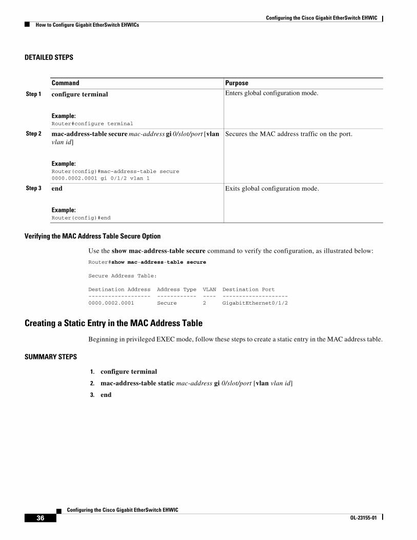
DETAILED STEPS
Verifying the MAC Address Table Secure Option
Use the show mac-address-table secure command to verify the configuration, as illustrated below:
Router#show mac-address-table secure
Secure Address Table:
Destination Address Address Type VLAN Destination Port------------------- ------------ ---- --------------------0000.0002.0001 Secure 2 GigabitEthernet0/1/2
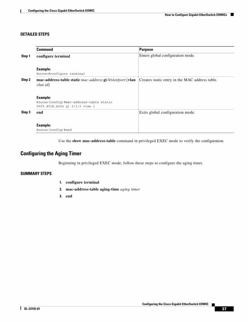
Creating a Static Entry in the MAC Address Table
Beginning in privileged EXEC mode, follow these steps to create a static entry in the MAC address table.
SUMMARY STEPS
1. configure terminal
2. mac-address-table static mac-address gi 0/slot/port [vlan vlan id]
3. end
Command Purpose
Step 1 configure terminal
Example:Router#configure terminal
Enters global configuration mode.
Step 2 mac-address-table secure mac-address gi 0/slot/port [vlan vlan id]
Example:Router(config)#mac-address-table secure 0000.0002.0001 gi 0/1/2 vlan 1
Secures the MAC address traffic on the port.
Step 3 end
Example:Router(config)#end
Exits global configuration mode.
Configuring the Cisco Gigabit EtherSwitch EHWICHow to Configure Gigabit EtherSwitch EHWICs
37Configuring the Cisco Gigabit EtherSwitch EHWIC
OL-23155-01
DETAILED STEPS
Use the show mac-address-table command in privileged EXEC mode to verify the configuration.
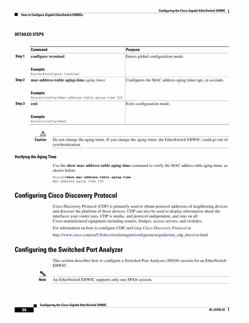
Configuring the Aging Timer
Beginning in privileged EXEC mode, follow these steps to configure the aging timer.
SUMMARY STEPS
1. configure terminal
2. mac-address-table aging-time aging timer
3. end
Command Purpose
Step 1 configure terminal
Example:Router#configure terminal
Enters global configuration mode.
Step 2 mac-address-table static mac-address gi 0/slot/port [vlan vlan id]
Example:Router(config)#mac-address-table static 0025.451b.b22e gi 0/1/2 vlan 1
Creates static entry in the MAC address table.
Step 3 end
Example:Router(config)#end
Exits global configuration mode.
Configuring the Cisco Gigabit EtherSwitch EHWICHow to Configure Gigabit EtherSwitch EHWICs
38Configuring the Cisco Gigabit EtherSwitch EHWIC
OL-23155-01
DETAILED STEPS
Caution Do not change the aging timer. If you change the aging timer, the EtherSwitch EHWIC could go out of synchronization.
Verifying the Aging Time
Use the show mac-address-table aging-time command to verify the MAC address table aging timer, as shown below:
Router#show mac-address-table aging-timeMac address aging time 320
Configuring Cisco Discovery ProtocolCisco Discovery Protocol (CDP) is primarily used to obtain protocol addresses of neighboring devices and discover the platform of those devices. CDP can also be used to display information about the interfaces your router uses. CDP is media- and protocol-independent, and runs on all Cisco-manufactured equipment including routers, bridges, access servers, and switches.
For information on how to configure CDP, seeUsing Cisco Discovery Protocol at
http://www.cisco.com/en/US/docs/ios/netmgmt/configuration/guide/nm_cdp_discover.html
Configuring the Switched Port Analyzer This section describes how to configure a Switched Port Analyzer (SPAN) session for an EtherSwitch EHWIC.
Note An EtherSwitch EHWIC supports only one SPAN session.
Command Purpose
Step 1 configure terminal
Example:Router#configure terminal
Enters global configuration mode.
Step 2 mac-address-table aging-time aging timer
Example:Router(config)#mac-address-table aging-time 320
Configures the MAC address aging timer age, in seconds.
Step 3 end
Example:Router(config)#end
Exits configuration mode.
Configuring the Cisco Gigabit EtherSwitch EHWICHow to Configure Gigabit EtherSwitch EHWICs
39Configuring the Cisco Gigabit EtherSwitch EHWIC
OL-23155-01
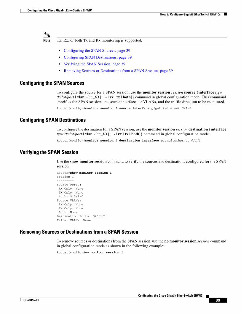
Note Tx, Rx, or both Tx and Rx monitoring is supported.
• Configuring the SPAN Sources, page 39
• Configuring SPAN Destinations, page 39
• Verifying the SPAN Session, page 39
• Removing Sources or Destinations from a SPAN Session, page 39
Configuring the SPAN Sources
To configure the source for a SPAN session, use the monitor session session source {interface type 0/slot/port | vlan vlan_ID [, | - | rx | tx | both]} command in global configuration mode. This command specifies the SPAN session, the source interfaces or VLANs, and the traffic direction to be monitored.
Router(config)#monitor session 1 source interface gigabitethernet 0/1/0
Configuring SPAN Destinations
To configure the destination for a SPAN session, use the monitor session session destination {interface type 0/slot/port | vlan vlan_ID [, | - | rx | tx | both]} command in global configuration mode.
Router(config)#monitor session 1 destination interface gigabitethernet 0/1/1
Verifying the SPAN Session
Use the show monitor session command to verify the sources and destinations configured for the SPAN session.
Router#show monitor session 1 Session 1 --------- Source Ports: RX Only: None TX Only: None Both: Gi0/1/0 Source VLANs: RX Only: None TX Only: None Both: None Destination Ports: Gi0/1/1 Filter VLANs: None
Removing Sources or Destinations from a SPAN Session
To remove sources or destinations from the SPAN session, use the no monitor session session command in global configuration mode as shown in the following example:
Router(config)#no monitor session 1
Configuring the Cisco Gigabit EtherSwitch EHWICHow to Configure Gigabit EtherSwitch EHWICs
40Configuring the Cisco Gigabit EtherSwitch EHWIC
OL-23155-01
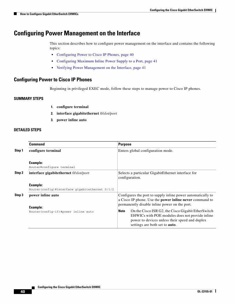
Configuring Power Management on the InterfaceThis section describes how to configure power management on the interface and contains the following topics:
• Configuring Power to Cisco IP Phones, page 40
• Configuring Maximum Inline Power Supply to a Port, page 41
• Verifying Power Management on the Interface, page 41
Configuring Power to Cisco IP Phones
Beginning in privileged EXEC mode, follow these steps to manage power to Cisco IP phones.
SUMMARY STEPS
1. configure terminal
2. interface gigabitethernet 0/slot/port
3. power inline auto
DETAILED STEPS
Command Purpose
Step 1 configure terminal
Example:Router#configure terminal
Enters global configuration mode.
Step 2 interface gigabitethernet 0/slot/port
Example:Router(config)#interface gigabitethernet 0/1/2
Selects a particular GigabitEthernet interface for configuration.
Step 3 power inline auto
Example:Router(config-if)#power inline auto
Configures the port to supply inline power automatically to a Cisco IP phone. Use the power inline never command to permanently disable inline power on the port.
Note On the Cisco ISR G2, the Cisco Gigabit EtherSwitch EHWICs with POE modules does not provide inline power to devices unless their speed and duplex settings are both set to auto.
Configuring the Cisco Gigabit EtherSwitch EHWICHow to Configure Gigabit EtherSwitch EHWICs
41Configuring the Cisco Gigabit EtherSwitch EHWIC
OL-23155-01
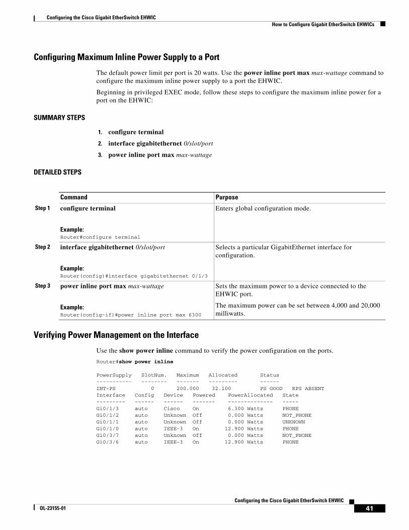
Configuring Maximum Inline Power Supply to a Port
The default power limit per port is 20 watts. Use the power inline port max max-wattage command to configure the maximum inline power supply to a port the EHWIC.
Beginning in privileged EXEC mode, follow these steps to configure the maximum inline power for a port on the EHWIC:
SUMMARY STEPS
1. configure terminal
2. interface gigabitethernet 0/slot/port
3. power inline port max max-wattage
DETAILED STEPS
Verifying Power Management on the Interface
Use the show power inline command to verify the power configuration on the ports.
Router#show power inline
PowerSupply SlotNum. Maximum Allocated Status----------- -------- ------- --------- ------INT-PS 0 200.000 32.100 PS GOOD RPS ABSENT Interface Config Device Powered PowerAllocated State --------- ------ ------ ------- -------------- ----- Gi0/1/3 auto Cisco On 6.300 Watts PHONE Gi0/1/2 auto Unknown Off 0.000 Watts NOT_PHONE Gi0/1/1 auto Unknown Off 0.000 Watts UNKNOWN Gi0/1/0 auto IEEE-3 On 12.900 Watts PHONE Gi0/3/7 auto Unknown Off 0.000 Watts NOT_PHONE Gi0/3/6 auto IEEE-3 On 12.900 Watts PHONE
Command Purpose
Step 1 configure terminal
Example:Router#configure terminal
Enters global configuration mode.
Step 2 interface gigabitethernet 0/slot/port
Example:Router(config)#interface gigabitethernet 0/1/3
Selects a particular GigabitEthernet interface for configuration.
Step 3 power inline port max max-wattage
Example:Router(config-if)#power inline port max 6300
Sets the maximum power to a device connected to the EHWIC port.
The maximum power can be set between 4,000 and 20,000 milliwatts.
Configuring the Cisco Gigabit EtherSwitch EHWICHow to Configure Gigabit EtherSwitch EHWICs
42Configuring the Cisco Gigabit EtherSwitch EHWIC
OL-23155-01
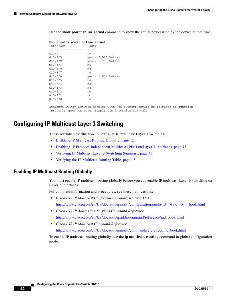
Use the show power inline actual command to show the actual power used by the device at that time.
Router#show power inline actualInterface Power-------------------- -----Gi1/0 no Gi0/1/3 yes ( 3.599 Watts)Gi0/1/2 yes ( 5.758 Watts)Gi0/1/1 no Gi0/1/0 no Gi0/3/7 no Gi0/3/6 yes ( 6.838 Watts)Gi0/3/5 no Gi0/3/4 no Gi0/3/3 no Gi0/3/2 no Gi0/3/1 no Gi0/3/0 no
Ethernet Switch Network Modules with PoE support should be reloaded to function properly upon PoE Power Supply OIR insertion/removal.
Configuring IP Multicast Layer 3 SwitchingThese sections describe how to configure IP multicast Layer 3 switching:
• Enabling IP Multicast Routing Globally, page 42
• Enabling IP Protocol-Independent Multicast (PIM) on Layer 3 Interfaces, page 43
• Verifying IP Multicast Layer 3 Switching Summary, page 43
• Verifying the IP Multicast Routing Table, page 45
Enabling IP Multicast Routing Globally
You must enable IP multicast routing globally before you can enable IP multicast Layer 3 switching on Layer 3 interfaces.
For complete information and procedures, see these publications:
• Cisco IOS IP Multicast Configuration Guide, Release 15.1
http://www.cisco.com/en/US/docs/ios/ipmulti/configuration/guide/15_1/imc_15_1_book.html
• Cisco IOS IP Addressing Services Command Reference
http://www.cisco.com/en/US/docs/ios/ipaddr/command/reference/iad_book.html
• Cisco IOS IP Multicast Command Reference
http://www.cisco.com/en/US/docs/ios/ipmulti/command/reference/imc_book.html
To enable IP multicast routing globally, use the ip multicast-routing command in global configuration mode.
Configuring the Cisco Gigabit EtherSwitch EHWICHow to Configure Gigabit EtherSwitch EHWICs
43Configuring the Cisco Gigabit EtherSwitch EHWIC
OL-23155-01
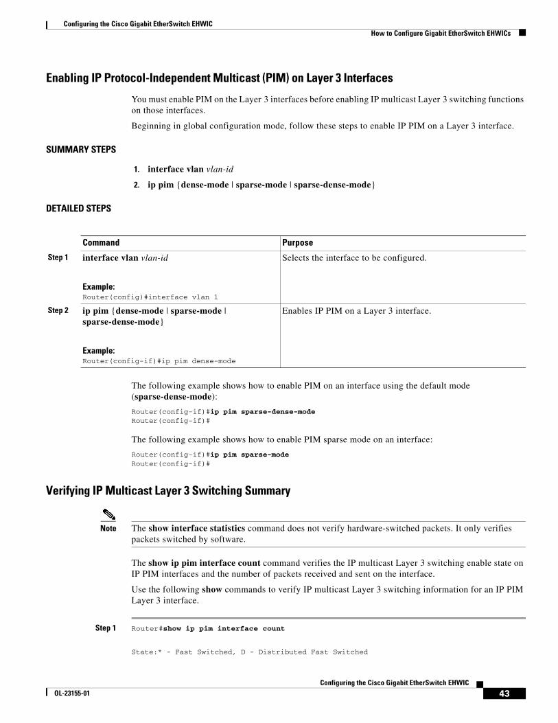
Enabling IP Protocol-Independent Multicast (PIM) on Layer 3 Interfaces
You must enable PIM on the Layer 3 interfaces before enabling IP multicast Layer 3 switching functions on those interfaces.
Beginning in global configuration mode, follow these steps to enable IP PIM on a Layer 3 interface.
SUMMARY STEPS
1. interface vlan vlan-id
2. ip pim {dense-mode | sparse-mode | sparse-dense-mode}
DETAILED STEPS
The following example shows how to enable PIM on an interface using the default mode (sparse-dense-mode):
Router(config-if)#ip pim sparse-dense-modeRouter(config-if)#
The following example shows how to enable PIM sparse mode on an interface:
Router(config-if)#ip pim sparse-modeRouter(config-if)#
Verifying IP Multicast Layer 3 Switching Summary
Note The show interface statistics command does not verify hardware-switched packets. It only verifies packets switched by software.
The show ip pim interface count command verifies the IP multicast Layer 3 switching enable state on IP PIM interfaces and the number of packets received and sent on the interface.
Use the following show commands to verify IP multicast Layer 3 switching information for an IP PIM Layer 3 interface.
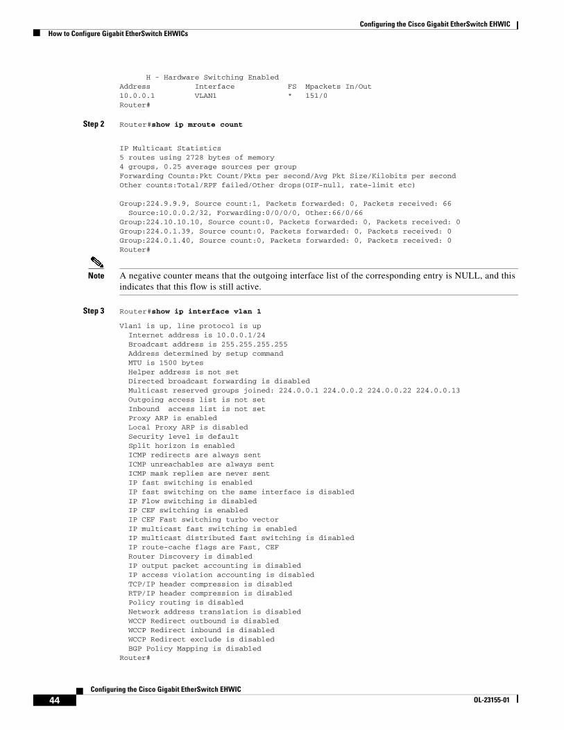
Step 1 Router#show ip pim interface count
State:* - Fast Switched, D - Distributed Fast Switched
Command Purpose
Step 1 interface vlan vlan-id
Example:Router(config)#interface vlan 1
Selects the interface to be configured.
Step 2 ip pim {dense-mode | sparse-mode | sparse-dense-mode}
Example:Router(config-if)#ip pim dense-mode
Enables IP PIM on a Layer 3 interface.
Configuring the Cisco Gigabit EtherSwitch EHWICHow to Configure Gigabit EtherSwitch EHWICs
44Configuring the Cisco Gigabit EtherSwitch EHWIC
OL-23155-01
H - Hardware Switching EnabledAddress Interface FS Mpackets In/Out10.0.0.1 VLAN1 * 151/0Router#
Step 2 Router#show ip mroute count
IP Multicast Statistics5 routes using 2728 bytes of memory4 groups, 0.25 average sources per groupForwarding Counts:Pkt Count/Pkts per second/Avg Pkt Size/Kilobits per secondOther counts:Total/RPF failed/Other drops(OIF-null, rate-limit etc) Group:224.9.9.9, Source count:1, Packets forwarded: 0, Packets received: 66 Source:10.0.0.2/32, Forwarding:0/0/0/0, Other:66/0/66Group:224.10.10.10, Source count:0, Packets forwarded: 0, Packets received: 0Group:224.0.1.39, Source count:0, Packets forwarded: 0, Packets received: 0Group:224.0.1.40, Source count:0, Packets forwarded: 0, Packets received: 0Router#
Note A negative counter means that the outgoing interface list of the corresponding entry is NULL, and this indicates that this flow is still active.
Step 3 Router#show ip interface vlan 1
Vlan1 is up, line protocol is up Internet address is 10.0.0.1/24 Broadcast address is 255.255.255.255 Address determined by setup command MTU is 1500 bytes Helper address is not set Directed broadcast forwarding is disabled Multicast reserved groups joined: 224.0.0.1 224.0.0.2 224.0.0.22 224.0.0.13 Outgoing access list is not set Inbound access list is not set Proxy ARP is enabled Local Proxy ARP is disabled Security level is default Split horizon is enabled ICMP redirects are always sent ICMP unreachables are always sent ICMP mask replies are never sent IP fast switching is enabled IP fast switching on the same interface is disabled IP Flow switching is disabled IP CEF switching is enabled IP CEF Fast switching turbo vector IP multicast fast switching is enabled IP multicast distributed fast switching is disabled IP route-cache flags are Fast, CEF Router Discovery is disabled IP output packet accounting is disabled IP access violation accounting is disabled TCP/IP header compression is disabled RTP/IP header compression is disabled Policy routing is disabled Network address translation is disabled WCCP Redirect outbound is disabled WCCP Redirect inbound is disabled WCCP Redirect exclude is disabled BGP Policy Mapping is disabledRouter#
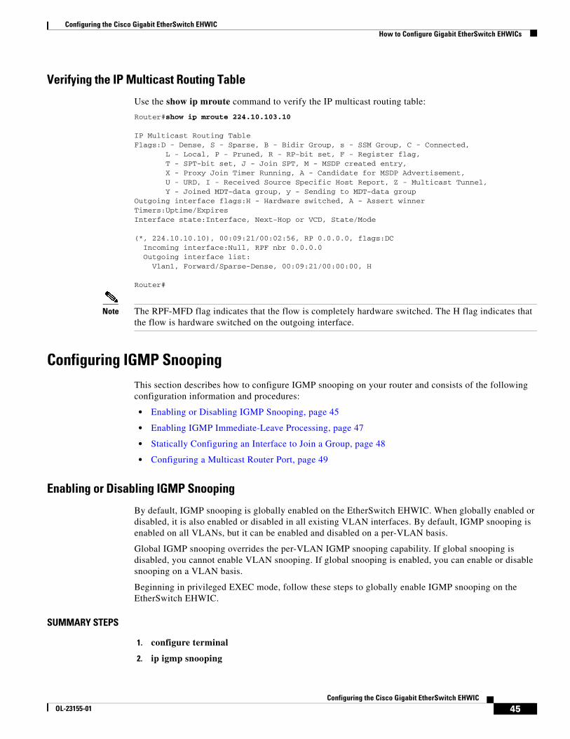
Configuring the Cisco Gigabit EtherSwitch EHWICHow to Configure Gigabit EtherSwitch EHWICs
45Configuring the Cisco Gigabit EtherSwitch EHWIC
OL-23155-01
Verifying the IP Multicast Routing Table
Use the show ip mroute command to verify the IP multicast routing table:
Router#show ip mroute 224.10.103.10
IP Multicast Routing TableFlags:D - Dense, S - Sparse, B - Bidir Group, s - SSM Group, C - Connected, L - Local, P - Pruned, R - RP-bit set, F - Register flag, T - SPT-bit set, J - Join SPT, M - MSDP created entry, X - Proxy Join Timer Running, A - Candidate for MSDP Advertisement, U - URD, I - Received Source Specific Host Report, Z - Multicast Tunnel, Y - Joined MDT-data group, y - Sending to MDT-data groupOutgoing interface flags:H - Hardware switched, A - Assert winnerTimers:Uptime/ExpiresInterface state:Interface, Next-Hop or VCD, State/Mode
(*, 224.10.10.10), 00:09:21/00:02:56, RP 0.0.0.0, flags:DC Incoming interface:Null, RPF nbr 0.0.0.0 Outgoing interface list: Vlan1, Forward/Sparse-Dense, 00:09:21/00:00:00, H
Router#
Note The RPF-MFD flag indicates that the flow is completely hardware switched. The H flag indicates that the flow is hardware switched on the outgoing interface.
Configuring IGMP SnoopingThis section describes how to configure IGMP snooping on your router and consists of the following configuration information and procedures:
• Enabling or Disabling IGMP Snooping, page 45
• Enabling IGMP Immediate-Leave Processing, page 47
• Statically Configuring an Interface to Join a Group, page 48
• Configuring a Multicast Router Port, page 49
Enabling or Disabling IGMP Snooping
By default, IGMP snooping is globally enabled on the EtherSwitch EHWIC. When globally enabled or disabled, it is also enabled or disabled in all existing VLAN interfaces. By default, IGMP snooping is enabled on all VLANs, but it can be enabled and disabled on a per-VLAN basis.
Global IGMP snooping overrides the per-VLAN IGMP snooping capability. If global snooping is disabled, you cannot enable VLAN snooping. If global snooping is enabled, you can enable or disable snooping on a VLAN basis.
Beginning in privileged EXEC mode, follow these steps to globally enable IGMP snooping on the EtherSwitch EHWIC.
SUMMARY STEPS
1. configure terminal
2. ip igmp snooping
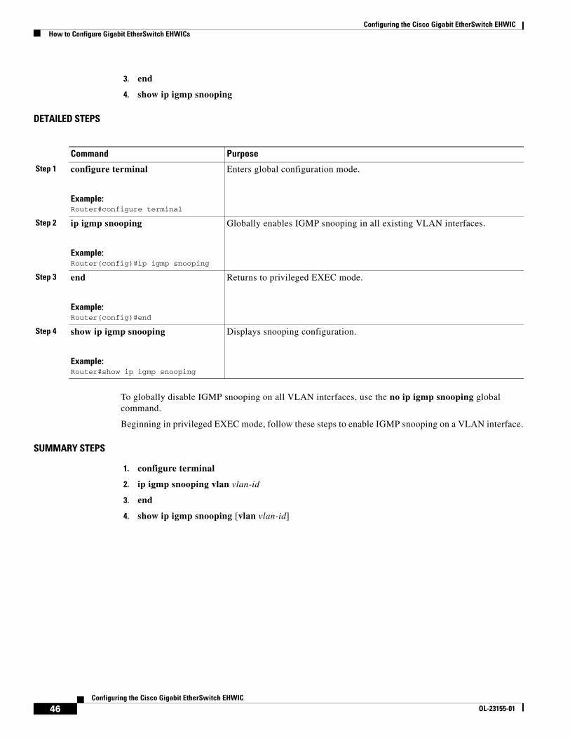
Configuring the Cisco Gigabit EtherSwitch EHWICHow to Configure Gigabit EtherSwitch EHWICs
46Configuring the Cisco Gigabit EtherSwitch EHWIC
OL-23155-01
3. end
4. show ip igmp snooping
DETAILED STEPS
To globally disable IGMP snooping on all VLAN interfaces, use the no ip igmp snooping global command.
Beginning in privileged EXEC mode, follow these steps to enable IGMP snooping on a VLAN interface.
SUMMARY STEPS
1. configure terminal
2. ip igmp snooping vlan vlan-id
3. end
4. show ip igmp snooping [vlan vlan-id]
Command Purpose
Step 1 configure terminal
Example:Router#configure terminal
Enters global configuration mode.
Step 2 ip igmp snooping
Example:Router(config)#ip igmp snooping
Globally enables IGMP snooping in all existing VLAN interfaces.
Step 3 end
Example:Router(config)#end
Returns to privileged EXEC mode.
Step 4 show ip igmp snooping
Example:Router#show ip igmp snooping
Displays snooping configuration.
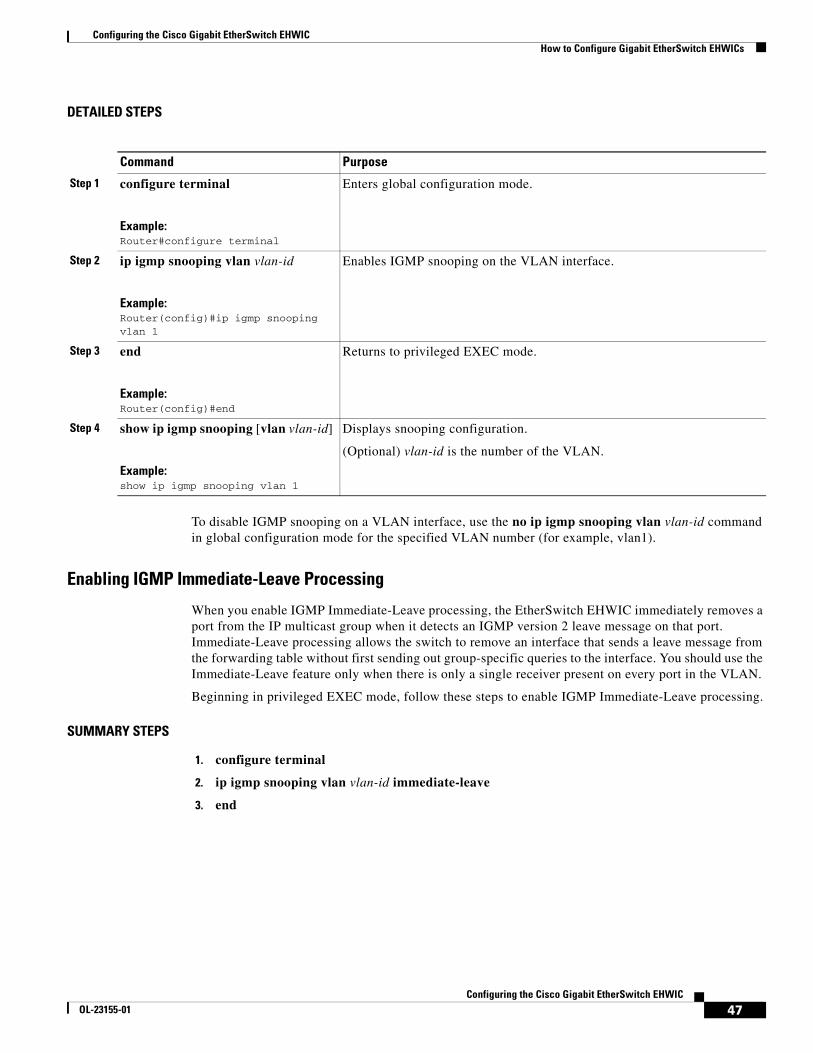
Configuring the Cisco Gigabit EtherSwitch EHWICHow to Configure Gigabit EtherSwitch EHWICs
47Configuring the Cisco Gigabit EtherSwitch EHWIC
OL-23155-01
DETAILED STEPS
To disable IGMP snooping on a VLAN interface, use the no ip igmp snooping vlan vlan-id command in global configuration mode for the specified VLAN number (for example, vlan1).
Enabling IGMP Immediate-Leave Processing
When you enable IGMP Immediate-Leave processing, the EtherSwitch EHWIC immediately removes a port from the IP multicast group when it detects an IGMP version 2 leave message on that port. Immediate-Leave processing allows the switch to remove an interface that sends a leave message from the forwarding table without first sending out group-specific queries to the interface. You should use the Immediate-Leave feature only when there is only a single receiver present on every port in the VLAN.
Beginning in privileged EXEC mode, follow these steps to enable IGMP Immediate-Leave processing.
SUMMARY STEPS
1. configure terminal
2. ip igmp snooping vlan vlan-id immediate-leave
3. end
Command Purpose
Step 1 configure terminal
Example:Router#configure terminal
Enters global configuration mode.
Step 2 ip igmp snooping vlan vlan-id
Example:Router(config)#ip igmp snooping vlan 1
Enables IGMP snooping on the VLAN interface.
Step 3 end
Example:Router(config)#end
Returns to privileged EXEC mode.
Step 4 show ip igmp snooping [vlan vlan-id]
Example:show ip igmp snooping vlan 1
Displays snooping configuration.
(Optional) vlan-id is the number of the VLAN.
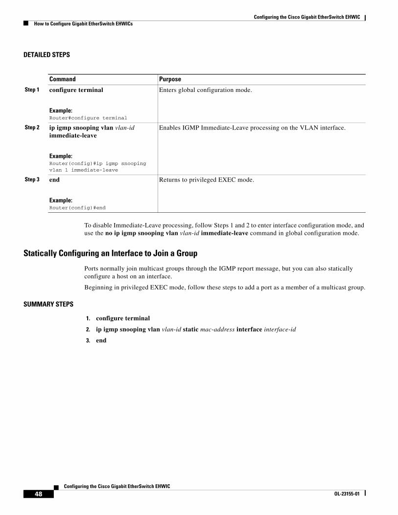
Configuring the Cisco Gigabit EtherSwitch EHWICHow to Configure Gigabit EtherSwitch EHWICs
48Configuring the Cisco Gigabit EtherSwitch EHWIC
OL-23155-01
DETAILED STEPS
To disable Immediate-Leave processing, follow Steps 1 and 2 to enter interface configuration mode, and use the no ip igmp snooping vlan vlan-id immediate-leave command in global configuration mode.
Statically Configuring an Interface to Join a Group
Ports normally join multicast groups through the IGMP report message, but you can also statically configure a host on an interface.
Beginning in privileged EXEC mode, follow these steps to add a port as a member of a multicast group.
SUMMARY STEPS
1. configure terminal
2. ip igmp snooping vlan vlan-id static mac-address interface interface-id
3. end
Command Purpose
Step 1 configure terminal
Example:Router#configure terminal
Enters global configuration mode.
Step 2 ip igmp snooping vlan vlan-id immediate-leave
Example:Router(config)#ip igmp snooping vlan 1 immediate-leave
Enables IGMP Immediate-Leave processing on the VLAN interface.
Step 3 end
Example:Router(config)#end
Returns to privileged EXEC mode.
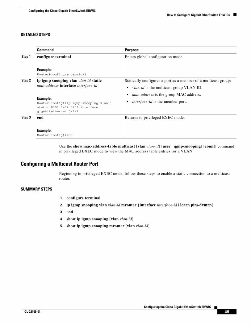
Configuring the Cisco Gigabit EtherSwitch EHWICHow to Configure Gigabit EtherSwitch EHWICs
49Configuring the Cisco Gigabit EtherSwitch EHWIC
OL-23155-01
DETAILED STEPS
Use the show mac-address-table multicast [vlan vlan-id] [user | igmp-snooping] [count] command in privileged EXEC mode to view the MAC address table entries for a VLAN.
Configuring a Multicast Router Port
Beginning in privileged EXEC mode, follow these steps to enable a static connection to a multicast router.
SUMMARY STEPS
1. configure terminal
2. ip igmp snooping vlan vlan-id mrouter {interface interface-id | learn pim-dvmrp}
3. end
4. show ip igmp snooping [vlan vlan-id]
5. show ip igmp snooping mrouter [vlan vlan-id]
Command Purpose
Step 1 configure terminal
Example:Router#configure terminal
Enters global configuration mode
Step 2 ip igmp snooping vlan vlan-id static mac-address interface interface-id
Example:Router(config)#ip igmp snooping vlan 1 static 0100.5e02.0203 interface gigabitethernet 0/1/2
Statically configures a port as a member of a multicast group:
• vlan-id is the multicast group VLAN ID.
• mac-address is the group MAC address.
• interface-id is the member port.
Step 3 end
Example:Router(config)#end
Returns to privileged EXEC mode.
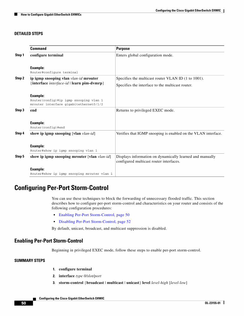
Configuring the Cisco Gigabit EtherSwitch EHWICHow to Configure Gigabit EtherSwitch EHWICs
50Configuring the Cisco Gigabit EtherSwitch EHWIC
OL-23155-01
DETAILED STEPS
Configuring Per-Port Storm-ControlYou can use these techniques to block the forwarding of unnecessary flooded traffic. This section describes how to configure per-port storm-control and characteristics on your router and consists of the following configuration procedures:
• Enabling Per-Port Storm-Control, page 50
• Disabling Per-Port Storm-Control, page 52
By default, unicast, broadcast, and multicast suppression is disabled.
Enabling Per-Port Storm-Control
Beginning in privileged EXEC mode, follow these steps to enable per-port storm-control.
SUMMARY STEPS
1. configure terminal
2. interface type 0/slot/port
3. storm-control {broadcast | multicast | unicast} level level-high [level-low]
Command Purpose
Step 1 configure terminal
Example:Router#configure terminal
Enters global configuration mode.
Step 2 ip igmp snooping vlan vlan-id mrouter {interface interface-id | learn pim-dvmrp}
Example:Router(config)#ip igmp snooping vlan 1 mrouter interface gigabitethernet0/1/2
Specifies the multicast router VLAN ID (1 to 1001).
Specifies the interface to the multicast router.
Step 3 end
Example:Router(config)#end
Returns to privileged EXEC mode.
Step 4 show ip igmp snooping [vlan vlan-id]
Example:Router#show ip igmp snooping vlan 1
Verifies that IGMP snooping is enabled on the VLAN interface.
Step 5 show ip igmp snooping mrouter [vlan vlan-id]
Example:Router#show ip igmp snooping mrouter vlan 1
Displays information on dynamically learned and manually configured multicast router interfaces.
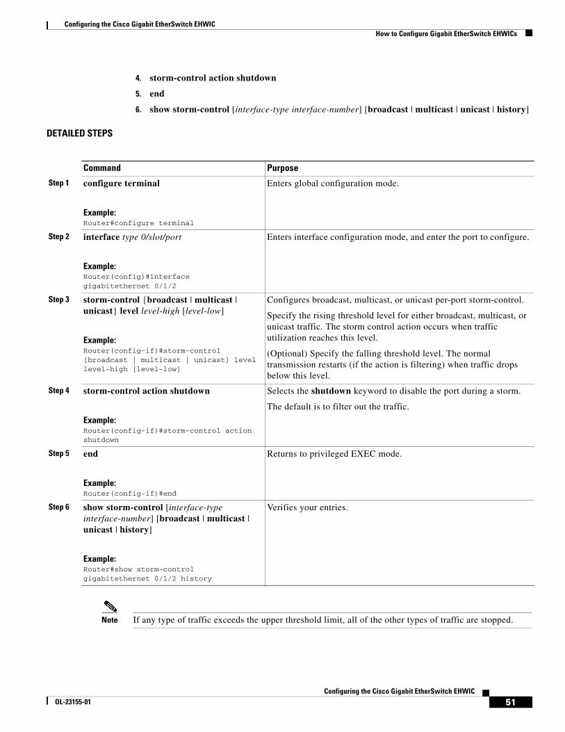
Configuring the Cisco Gigabit EtherSwitch EHWICHow to Configure Gigabit EtherSwitch EHWICs
51Configuring the Cisco Gigabit EtherSwitch EHWIC
OL-23155-01
4. storm-control action shutdown
5. end
6. show storm-control [interface-type interface-number] [broadcast | multicast | unicast | history]
DETAILED STEPS
Note If any type of traffic exceeds the upper threshold limit, all of the other types of traffic are stopped.
Command Purpose
Step 1 configure terminal
Example:Router#configure terminal
Enters global configuration mode.
Step 2 interface type 0/slot/port
Example:Router(config)#interface gigabitethernet 0/1/2
Enters interface configuration mode, and enter the port to configure.
Step 3 storm-control {broadcast | multicast | unicast} level level-high [level-low]
Example:Router(config-if)#storm-control {broadcast | multicast | unicast} level level-high [level-low]
Configures broadcast, multicast, or unicast per-port storm-control.
Specify the rising threshold level for either broadcast, multicast, or unicast traffic. The storm control action occurs when traffic utilization reaches this level.
(Optional) Specify the falling threshold level. The normal transmission restarts (if the action is filtering) when traffic drops below this level.
Step 4 storm-control action shutdown
Example:Router(config-if)#storm-control action shutdown
Selects the shutdown keyword to disable the port during a storm.
The default is to filter out the traffic.
Step 5 end
Example:Router(config-if)#end
Returns to privileged EXEC mode.
Step 6 show storm-control [interface-type interface-number] [broadcast | multicast | unicast | history]
Example:Router#show storm-control gigabitethernet 0/1/2 history
Verifies your entries.

Configuring the Cisco Gigabit EtherSwitch EHWICHow to Configure Gigabit EtherSwitch EHWICs
52Configuring the Cisco Gigabit EtherSwitch EHWIC
OL-23155-01
Disabling Per-Port Storm-Control
Beginning in privileged EXEC mode, follow these steps to disable per-port storm-control.
SUMMARY STEPS
1. configure terminal
2. interface type 0/slot/port
3. no storm-control {{broadcast | multicast | unicast} level | action shutdown}
4. end
DETAILED STEPS
Use the show storm-control [interface-type interface-number] [broadcast | multicast | unicast | history] command in privileged EXEC mode to verify your entries.
Configuring Fallback BridgingThis section describes how to configure fallback bridging on your switch. It contains the following configuration information:
• Understanding the Default Fallback Bridging Configuration, page 53
• Creating a Bridge Group, page 53
• Preventing the Forwarding of Dynamically Learned Stations, page 55
Command Purpose
Step 1 configure terminal
Example:Router#configure terminal
Enters global configuration mode.
Step 2 interface type 0/slot/port
Example:Router(config)#interface gigabitethernet 0/1/2
Enters interface configuration mode, and enter the port to configure.
Step 3 no storm-control {{broadcast | multicast | unicast} level | action shutdown}
Example:Router(config-if)#no storm-control action shutdown
Disables per-port storm control or the specified storm control action.
Step 4 end
Example:Router(config-if)#end
Returns to privileged EXEC mode.
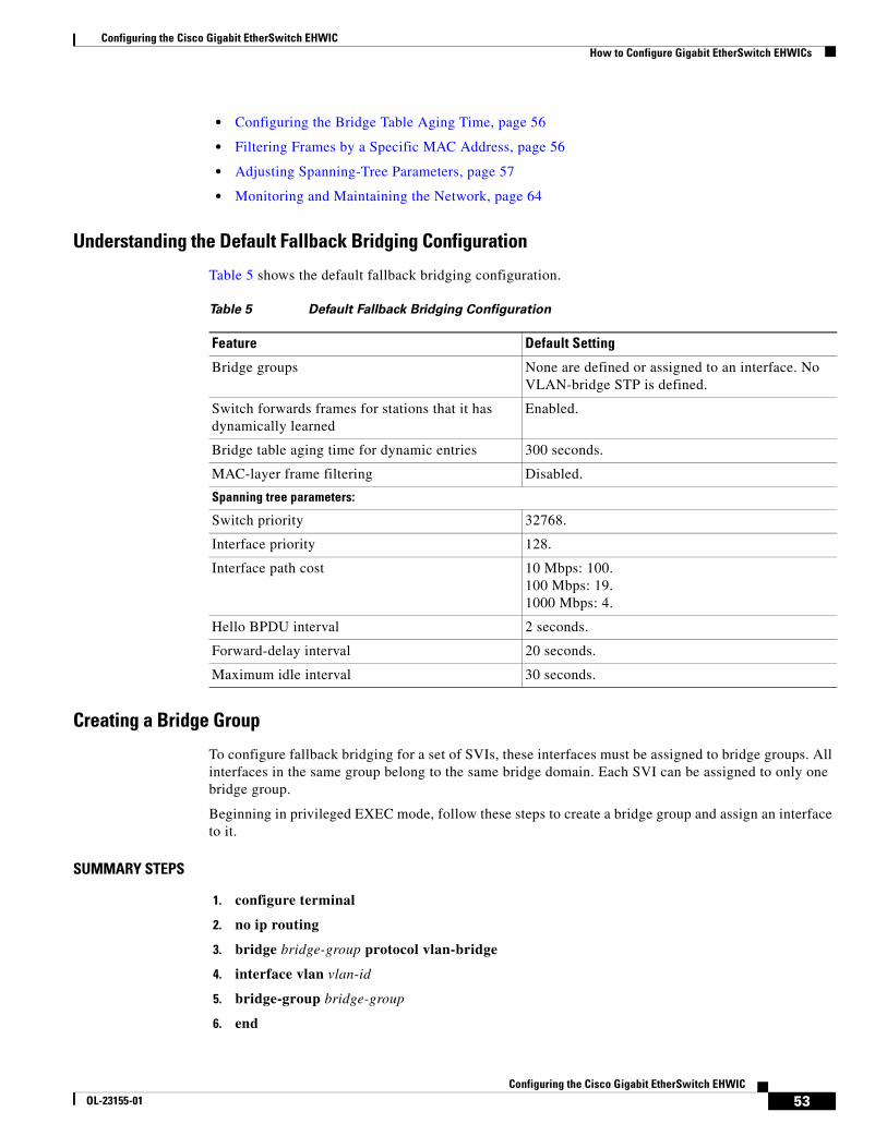
Configuring the Cisco Gigabit EtherSwitch EHWICHow to Configure Gigabit EtherSwitch EHWICs
53Configuring the Cisco Gigabit EtherSwitch EHWIC
OL-23155-01
• Configuring the Bridge Table Aging Time, page 56
• Filtering Frames by a Specific MAC Address, page 56
• Adjusting Spanning-Tree Parameters, page 57
• Monitoring and Maintaining the Network, page 64
Understanding the Default Fallback Bridging Configuration
Table 5 shows the default fallback bridging configuration.
Creating a Bridge Group
To configure fallback bridging for a set of SVIs, these interfaces must be assigned to bridge groups. All interfaces in the same group belong to the same bridge domain. Each SVI can be assigned to only one bridge group.
Beginning in privileged EXEC mode, follow these steps to create a bridge group and assign an interface to it.
SUMMARY STEPS
1. configure terminal
2. no ip routing
3. bridge bridge-group protocol vlan-bridge
4. interface vlan vlan-id
5. bridge-group bridge-group
6. end
Table 5 Default Fallback Bridging Configuration
Feature Default Setting
Bridge groups None are defined or assigned to an interface. No VLAN-bridge STP is defined.
Switch forwards frames for stations that it has dynamically learned
Enabled.
Bridge table aging time for dynamic entries 300 seconds.
MAC-layer frame filtering Disabled.
Spanning tree parameters:
Switch priority 32768.
Interface priority 128.
Interface path cost 10 Mbps: 100.100 Mbps: 19.1000 Mbps: 4.
Hello BPDU interval 2 seconds.
Forward-delay interval 20 seconds.
Maximum idle interval 30 seconds.
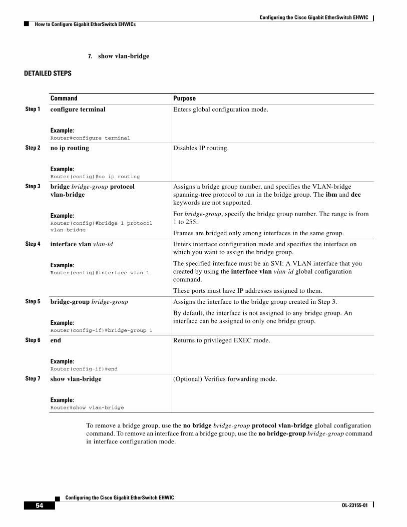
Configuring the Cisco Gigabit EtherSwitch EHWICHow to Configure Gigabit EtherSwitch EHWICs
54Configuring the Cisco Gigabit EtherSwitch EHWIC
OL-23155-01
7. show vlan-bridge
DETAILED STEPS
To remove a bridge group, use the no bridge bridge-group protocol vlan-bridge global configuration command. To remove an interface from a bridge group, use the no bridge-group bridge-group command in interface configuration mode.
Command Purpose
Step 1 configure terminal
Example:Router#configure terminal
Enters global configuration mode.
Step 2 no ip routing
Example:Router(config)#no ip routing
Disables IP routing.
Step 3 bridge bridge-group protocol vlan-bridge
Example:Router(config)#bridge 1 protocol vlan-bridge
Assigns a bridge group number, and specifies the VLAN-bridge spanning-tree protocol to run in the bridge group. The ibm and dec keywords are not supported.
For bridge-group, specify the bridge group number. The range is from 1 to 255.
Frames are bridged only among interfaces in the same group.
Step 4 interface vlan vlan-id
Example:Router(config)#interface vlan 1
Enters interface configuration mode and specifies the interface on which you want to assign the bridge group.
The specified interface must be an SVI: A VLAN interface that you created by using the interface vlan vlan-id global configuration command.
These ports must have IP addresses assigned to them.
Step 5 bridge-group bridge-group
Example:Router(config-if)#bridge-group 1
Assigns the interface to the bridge group created in Step 3.
By default, the interface is not assigned to any bridge group. An interface can be assigned to only one bridge group.
Step 6 end
Example:Router(config-if)#end
Returns to privileged EXEC mode.
Step 7 show vlan-bridge
Example:Router#show vlan-bridge
(Optional) Verifies forwarding mode.
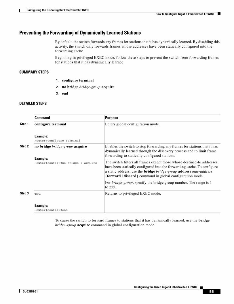
Configuring the Cisco Gigabit EtherSwitch EHWICHow to Configure Gigabit EtherSwitch EHWICs
55Configuring the Cisco Gigabit EtherSwitch EHWIC
OL-23155-01
Preventing the Forwarding of Dynamically Learned Stations
By default, the switch forwards any frames for stations that it has dynamically learned. By disabling this activity, the switch only forwards frames whose addresses have been statically configured into the forwarding cache.
Beginning in privileged EXEC mode, follow these steps to prevent the switch from forwarding frames for stations that it has dynamically learned.
SUMMARY STEPS
1. configure terminal
2. no bridge bridge-group acquire
3. end
DETAILED STEPS
To cause the switch to forward frames to stations that it has dynamically learned, use the bridge bridge-group acquire command in global configuration mode.
Command Purpose
Step 1 configure terminal
Example:Router#configure terminal
Enters global configuration mode.
Step 2 no bridge bridge-group acquire
Example:Router(config)#no bridge 1 acquire
Enables the switch to stop forwarding any frames for stations that it has dynamically learned through the discovery process and to limit frame forwarding to statically configured stations.
The switch filters all frames except those whose destined-to addresses have been statically configured into the forwarding cache. To configure a static address, use the bridge bridge-group address mac-address {forward | discard} command in global configuration mode.
For bridge-group, specify the bridge group number. The range is 1 to 255.
Step 3 end
Example:Router(config)#end
Returns to privileged EXEC mode.
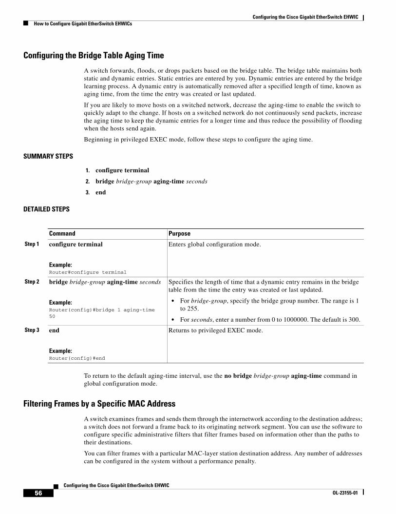
Configuring the Cisco Gigabit EtherSwitch EHWICHow to Configure Gigabit EtherSwitch EHWICs
56Configuring the Cisco Gigabit EtherSwitch EHWIC
OL-23155-01
Configuring the Bridge Table Aging Time
A switch forwards, floods, or drops packets based on the bridge table. The bridge table maintains both static and dynamic entries. Static entries are entered by you. Dynamic entries are entered by the bridge learning process. A dynamic entry is automatically removed after a specified length of time, known as aging time, from the time the entry was created or last updated.
If you are likely to move hosts on a switched network, decrease the aging-time to enable the switch to quickly adapt to the change. If hosts on a switched network do not continuously send packets, increase the aging time to keep the dynamic entries for a longer time and thus reduce the possibility of flooding when the hosts send again.
Beginning in privileged EXEC mode, follow these steps to configure the aging time.
SUMMARY STEPS
1. configure terminal
2. bridge bridge-group aging-time seconds
3. end
DETAILED STEPS
To return to the default aging-time interval, use the no bridge bridge-group aging-time command in global configuration mode.
Filtering Frames by a Specific MAC Address
A switch examines frames and sends them through the internetwork according to the destination address; a switch does not forward a frame back to its originating network segment. You can use the software to configure specific administrative filters that filter frames based on information other than the paths to their destinations.
You can filter frames with a particular MAC-layer station destination address. Any number of addresses can be configured in the system without a performance penalty.
Command Purpose
Step 1 configure terminal
Example:Router#configure terminal
Enters global configuration mode.
Step 2 bridge bridge-group aging-time seconds
Example:Router(config)#bridge 1 aging-time 50
Specifies the length of time that a dynamic entry remains in the bridge table from the time the entry was created or last updated.
• For bridge-group, specify the bridge group number. The range is 1 to 255.
• For seconds, enter a number from 0 to 1000000. The default is 300.
Step 3 end
Example:Router(config)#end
Returns to privileged EXEC mode.
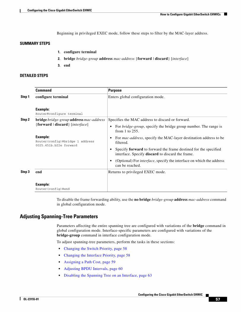
Configuring the Cisco Gigabit EtherSwitch EHWICHow to Configure Gigabit EtherSwitch EHWICs
57Configuring the Cisco Gigabit EtherSwitch EHWIC
OL-23155-01
Beginning in privileged EXEC mode, follow these steps to filter by the MAC-layer address.
SUMMARY STEPS
1. configure terminal
2. bridge bridge-group address mac-address {forward | discard} [interface]
3. end
DETAILED STEPS
To disable the frame forwarding ability, use the no bridge bridge-group address mac-address command in global configuration mode.
Adjusting Spanning-Tree Parameters
Parameters affecting the entire spanning tree are configured with variations of the bridge command in global configuration mode. Interface-specific parameters are configured with variations of the bridge-group command in interface configuration mode.
To adjust spanning-tree parameters, perform the tasks in these sections:
• Changing the Switch Priority, page 58
• Changing the Interface Priority, page 58
• Assigning a Path Cost, page 59
• Adjusting BPDU Intervals, page 60
• Disabling the Spanning Tree on an Interface, page 63
Command Purpose
Step 1 configure terminal
Example:Router#configure terminal
Enters global configuration mode.
Step 2 bridge bridge-group address mac-address {forward | discard} [interface]
Example:Router(config)#bridge 1 address 0025.451b.b22e forward
Specifies the MAC address to discard or forward.
• For bridge-group, specify the bridge group number. The range is from 1 to 255.
• For mac-address, specify the MAC-layer destination address to be filtered.
• Specify forward to forward the frame destined for the specified interface. Specify discard to discard the frame.
• (Optional) For interface, specify the interface on which the address can be reached.
Step 3 end
Example:Router(config)#end
Returns to privileged EXEC mode.
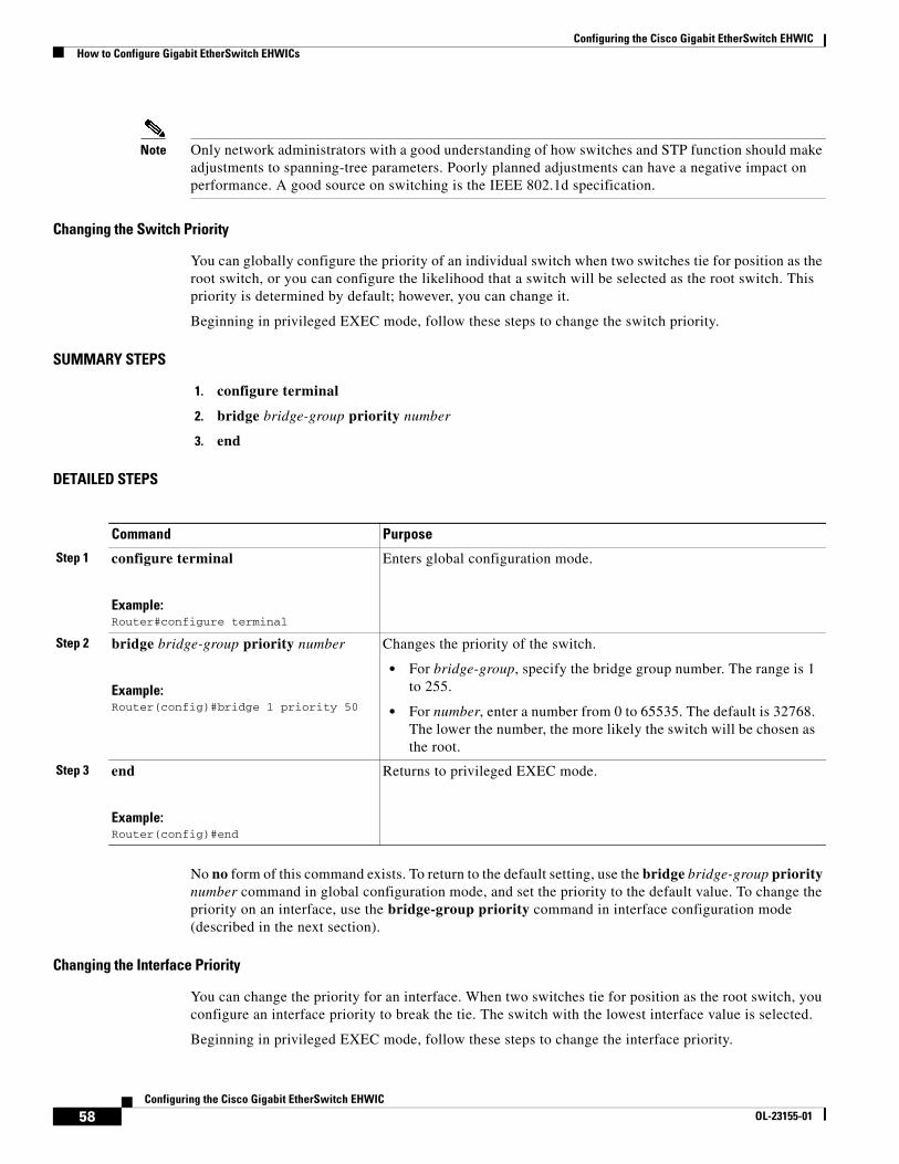
Configuring the Cisco Gigabit EtherSwitch EHWICHow to Configure Gigabit EtherSwitch EHWICs
58Configuring the Cisco Gigabit EtherSwitch EHWIC
OL-23155-01
Note Only network administrators with a good understanding of how switches and STP function should make adjustments to spanning-tree parameters. Poorly planned adjustments can have a negative impact on performance. A good source on switching is the IEEE 802.1d specification.
Changing the Switch Priority
You can globally configure the priority of an individual switch when two switches tie for position as the root switch, or you can configure the likelihood that a switch will be selected as the root switch. This priority is determined by default; however, you can change it.
Beginning in privileged EXEC mode, follow these steps to change the switch priority.
SUMMARY STEPS
1. configure terminal
2. bridge bridge-group priority number
3. end
DETAILED STEPS
No no form of this command exists. To return to the default setting, use the bridge bridge-group priority number command in global configuration mode, and set the priority to the default value. To change the priority on an interface, use the bridge-group priority command in interface configuration mode (described in the next section).
Changing the Interface Priority
You can change the priority for an interface. When two switches tie for position as the root switch, you configure an interface priority to break the tie. The switch with the lowest interface value is selected.
Beginning in privileged EXEC mode, follow these steps to change the interface priority.
Command Purpose
Step 1 configure terminal
Example:Router#configure terminal
Enters global configuration mode.
Step 2 bridge bridge-group priority number
Example:Router(config)#bridge 1 priority 50
Changes the priority of the switch.
• For bridge-group, specify the bridge group number. The range is 1 to 255.
• For number, enter a number from 0 to 65535. The default is 32768. The lower the number, the more likely the switch will be chosen as the root.
Step 3 end
Example:Router(config)#end
Returns to privileged EXEC mode.
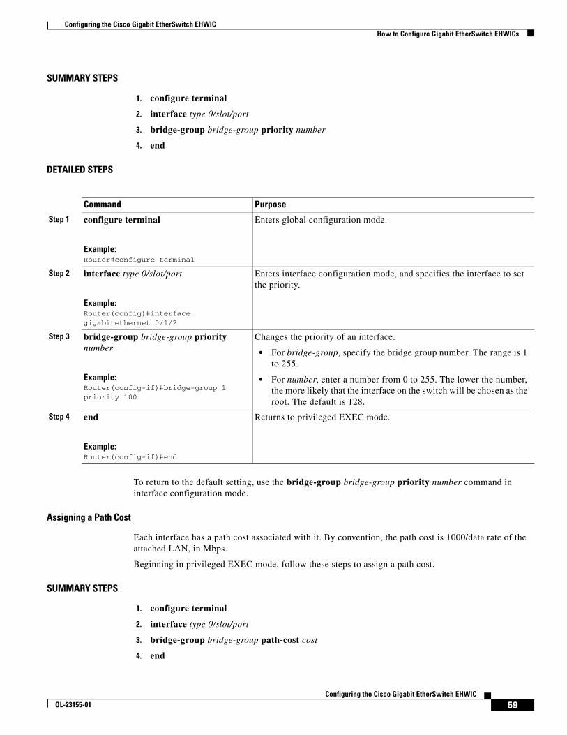
Configuring the Cisco Gigabit EtherSwitch EHWICHow to Configure Gigabit EtherSwitch EHWICs
59Configuring the Cisco Gigabit EtherSwitch EHWIC
OL-23155-01
SUMMARY STEPS
1. configure terminal
2. interface type 0/slot/port
3. bridge-group bridge-group priority number
4. end
DETAILED STEPS
To return to the default setting, use the bridge-group bridge-group priority number command in interface configuration mode.
Assigning a Path Cost
Each interface has a path cost associated with it. By convention, the path cost is 1000/data rate of the attached LAN, in Mbps.
Beginning in privileged EXEC mode, follow these steps to assign a path cost.
SUMMARY STEPS
1. configure terminal
2. interface type 0/slot/port
3. bridge-group bridge-group path-cost cost
4. end
Command Purpose
Step 1 configure terminal
Example:Router#configure terminal
Enters global configuration mode.
Step 2 interface type 0/slot/port
Example:Router(config)#interface gigabitethernet 0/1/2
Enters interface configuration mode, and specifies the interface to set the priority.
Step 3 bridge-group bridge-group priority number
Example:Router(config-if)#bridge-group 1 priority 100
Changes the priority of an interface.
• For bridge-group, specify the bridge group number. The range is 1 to 255.
• For number, enter a number from 0 to 255. The lower the number, the more likely that the interface on the switch will be chosen as the root. The default is 128.
Step 4 end
Example:Router(config-if)#end
Returns to privileged EXEC mode.
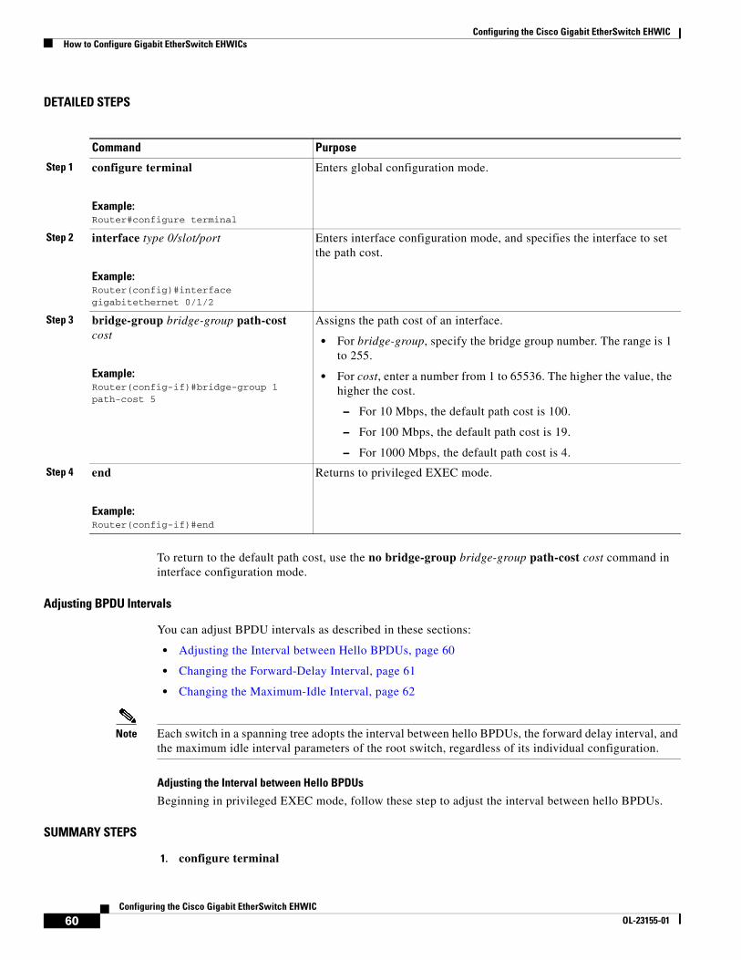
Configuring the Cisco Gigabit EtherSwitch EHWICHow to Configure Gigabit EtherSwitch EHWICs
60Configuring the Cisco Gigabit EtherSwitch EHWIC
OL-23155-01
DETAILED STEPS
To return to the default path cost, use the no bridge-group bridge-group path-cost cost command in interface configuration mode.
Adjusting BPDU Intervals
You can adjust BPDU intervals as described in these sections:
• Adjusting the Interval between Hello BPDUs, page 60
• Changing the Forward-Delay Interval, page 61
• Changing the Maximum-Idle Interval, page 62
Note Each switch in a spanning tree adopts the interval between hello BPDUs, the forward delay interval, and the maximum idle interval parameters of the root switch, regardless of its individual configuration.
Adjusting the Interval between Hello BPDUs
Beginning in privileged EXEC mode, follow these step to adjust the interval between hello BPDUs.
SUMMARY STEPS
1. configure terminal
Command Purpose
Step 1 configure terminal
Example:Router#configure terminal
Enters global configuration mode.
Step 2 interface type 0/slot/port
Example:Router(config)#interface gigabitethernet 0/1/2
Enters interface configuration mode, and specifies the interface to set the path cost.
Step 3 bridge-group bridge-group path-cost cost
Example:Router(config-if)#bridge-group 1 path-cost 5
Assigns the path cost of an interface.
• For bridge-group, specify the bridge group number. The range is 1 to 255.
• For cost, enter a number from 1 to 65536. The higher the value, the higher the cost.
– For 10 Mbps, the default path cost is 100.
– For 100 Mbps, the default path cost is 19.
– For 1000 Mbps, the default path cost is 4.
Step 4 end
Example:Router(config-if)#end
Returns to privileged EXEC mode.
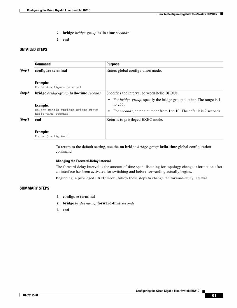
Configuring the Cisco Gigabit EtherSwitch EHWICHow to Configure Gigabit EtherSwitch EHWICs
61Configuring the Cisco Gigabit EtherSwitch EHWIC
OL-23155-01
2. bridge bridge-group hello-time seconds
3. end
DETAILED STEPS
To return to the default setting, use the no bridge bridge-group hello-time global configuration command.
Changing the Forward-Delay Interval
The forward-delay interval is the amount of time spent listening for topology change information after an interface has been activated for switching and before forwarding actually begins.
Beginning in privileged EXEC mode, follow these steps to change the forward-delay interval.
SUMMARY STEPS
1. configure terminal
2. bridge bridge-group forward-time seconds
3. end
Command Purpose
Step 1 configure terminal
Example:Router#configure terminal
Enters global configuration mode.
Step 2 bridge bridge-group hello-time seconds
Example:Router(config)#bridge bridge-group hello-time seconds
Specifies the interval between hello BPDUs.
• For bridge-group, specify the bridge group number. The range is 1 to 255.
• For seconds, enter a number from 1 to 10. The default is 2 seconds.
Step 3 end
Example:Router(config)#end
Returns to privileged EXEC mode.
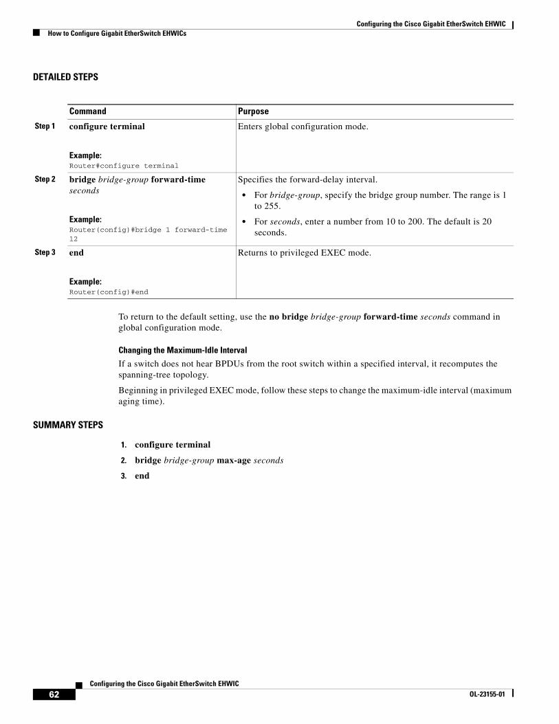
Configuring the Cisco Gigabit EtherSwitch EHWICHow to Configure Gigabit EtherSwitch EHWICs
62Configuring the Cisco Gigabit EtherSwitch EHWIC
OL-23155-01
DETAILED STEPS
To return to the default setting, use the no bridge bridge-group forward-time seconds command in global configuration mode.
Changing the Maximum-Idle Interval
If a switch does not hear BPDUs from the root switch within a specified interval, it recomputes the spanning-tree topology.
Beginning in privileged EXEC mode, follow these steps to change the maximum-idle interval (maximum aging time).
SUMMARY STEPS
1. configure terminal
2. bridge bridge-group max-age seconds
3. end
Command Purpose
Step 1 configure terminal
Example:Router#configure terminal
Enters global configuration mode.
Step 2 bridge bridge-group forward-time seconds
Example:Router(config)#bridge 1 forward-time 12
Specifies the forward-delay interval.
• For bridge-group, specify the bridge group number. The range is 1 to 255.
• For seconds, enter a number from 10 to 200. The default is 20 seconds.
Step 3 end
Example:Router(config)#end
Returns to privileged EXEC mode.
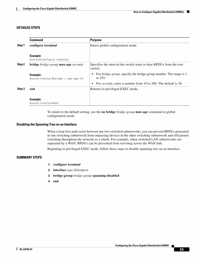
Configuring the Cisco Gigabit EtherSwitch EHWICHow to Configure Gigabit EtherSwitch EHWICs
63Configuring the Cisco Gigabit EtherSwitch EHWIC
OL-23155-01
DETAILED STEPS
To return to the default setting, use the no bridge bridge-group max-age command in global configuration mode.
Disabling the Spanning Tree on an Interface
When a loop-free path exists between any two switched subnetworks, you can prevent BPDUs generated in one switching subnetwork from impacting devices in the other switching subnetwork and still permit switching throughout the network as a whole. For example, when switched LAN subnetworks are separated by a WAN, BPDUs can be prevented from traveling across the WAN link.
Beginning in privileged EXEC mode, follow these steps to disable spanning tree on an interface.
SUMMARY STEPS
1. configure terminal
2. interface type 0/slot/port
3. bridge-group bridge-group spanning-disabled
4. end
Command Purpose
Step 1 configure terminal
Example:Router#configure terminal
Enters global configuration mode.
Step 2 bridge bridge-group max-age seconds
Example:Router(config)#bridge 1 max-age 50
Specifies the interval the switch waits to hear BPDUs from the root switch.
• For bridge-group, specify the bridge group number. The range is 1 to 255.
• For seconds, enter a number from 10 to 200. The default is 30.
Step 3 end
Example:Router(config)#end
Returns to privileged EXEC mode.
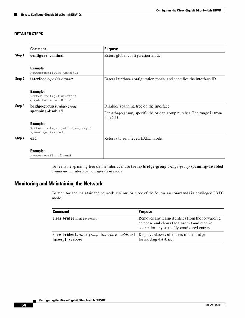
Configuring the Cisco Gigabit EtherSwitch EHWICHow to Configure Gigabit EtherSwitch EHWICs
64Configuring the Cisco Gigabit EtherSwitch EHWIC
OL-23155-01
DETAILED STEPS
To reenable spanning tree on the interface, use the no bridge-group bridge-group spanning-disabled command in interface configuration mode.
Monitoring and Maintaining the Network
To monitor and maintain the network, use one or more of the following commands in privileged EXEC mode.
Command Purpose
Step 1 configure terminal
Example:Router#configure terminal
Enters global configuration mode.
Step 2 interface type 0/slot/port
Example:Router(config)#interface gigabitethernet 0/1/2
Enters interface configuration mode, and specifies the interface ID.
Step 3 bridge-group bridge-group spanning-disabled
Example:Router(config-if)#bridge-group 1 spanning-disabled
Disables spanning tree on the interface.
For bridge-group, specify the bridge group number. The range is from 1 to 255.
Step 4 end
Example:Router(config-if)#end
Returns to privileged EXEC mode.
Command Purpose
clear bridge bridge-group Removes any learned entries from the forwarding database and clears the transmit and receive counts for any statically configured entries.
show bridge [bridge-group] [interface] [address] [group] [verbose]
Displays classes of entries in the bridge forwarding database.

Configuring the Cisco Gigabit EtherSwitch EHWICHow to Configure Gigabit EtherSwitch EHWICs
65Configuring the Cisco Gigabit EtherSwitch EHWIC
OL-23155-01
Configuring Separate Voice and Data SubnetsFor ease of network administration and increased scalability, network managers can configure the Cisco Gigabit EtherSwitch EHWIC to support Cisco IP phones such that the voice and data traffic reside on separate subnets. You should always use separate VLANs when you are able to segment the existing IP address space of your branch office.
User priority bits in the 802.1p portion of the 802.1Q standard header are used to provide prioritization in Ethernet switches. This is a vital component in designing Cisco AVVID networks.
The Cisco Gigabit EtherSwitch EHWIC provides the performance and intelligent services of Cisco IOS software for branch office applications. The Cisco Gigabit EtherSwitch EHWIC can identify user applications—such as voice or multicast video—and classify traffic with the appropriate priority levels.
Note See Cisco AVVID QoS Design Guide for more information on how to implement end-to-end QoS as you deploy Cisco AVVID solutions.
Beginning in EXEC mode, follow these steps to automatically configure Cisco IP phones to send voice traffic on the voice VLAN ID (VVID) on a per-port basis (see the “Voice Traffic and VVID” section on page 66).
SUMMARY STEPS
1. enable
2. configure terminal
3. interface type 0/slot/port
4. switchport mode trunk
5. switchport voice vlan vlan-id
6. end
DETAILED STEPS
Command Purpose
Step 1 enable
Example:Router> enable
Enters the privileged EXEC mode. A preset password may be required to enter this mode.
Step 2 configure terminal
Example:Router#configure terminal
Enters global configuration mode.
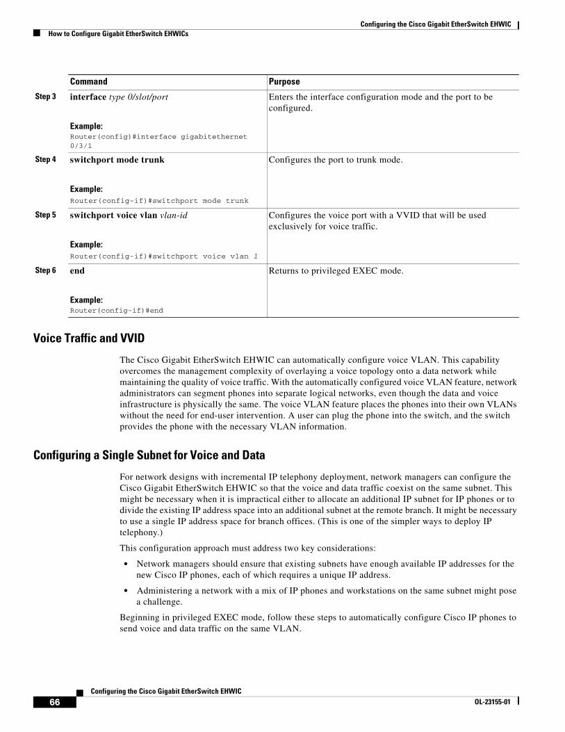
Configuring the Cisco Gigabit EtherSwitch EHWICHow to Configure Gigabit EtherSwitch EHWICs
66Configuring the Cisco Gigabit EtherSwitch EHWIC
OL-23155-01
Voice Traffic and VVID
The Cisco Gigabit EtherSwitch EHWIC can automatically configure voice VLAN. This capability overcomes the management complexity of overlaying a voice topology onto a data network while maintaining the quality of voice traffic. With the automatically configured voice VLAN feature, network administrators can segment phones into separate logical networks, even though the data and voice infrastructure is physically the same. The voice VLAN feature places the phones into their own VLANs without the need for end-user intervention. A user can plug the phone into the switch, and the switch provides the phone with the necessary VLAN information.
Configuring a Single Subnet for Voice and Data
For network designs with incremental IP telephony deployment, network managers can configure the Cisco Gigabit EtherSwitch EHWIC so that the voice and data traffic coexist on the same subnet. This might be necessary when it is impractical either to allocate an additional IP subnet for IP phones or to divide the existing IP address space into an additional subnet at the remote branch. It might be necessary to use a single IP address space for branch offices. (This is one of the simpler ways to deploy IP telephony.)
This configuration approach must address two key considerations:
• Network managers should ensure that existing subnets have enough available IP addresses for the new Cisco IP phones, each of which requires a unique IP address.
• Administering a network with a mix of IP phones and workstations on the same subnet might pose a challenge.
Beginning in privileged EXEC mode, follow these steps to automatically configure Cisco IP phones to send voice and data traffic on the same VLAN.
Step 3 interface type 0/slot/port
Example:Router(config)#interface gigabitethernet 0/3/1
Enters the interface configuration mode and the port to be configured.
Step 4 switchport mode trunk
Example:Router(config-if)#switchport mode trunk
Configures the port to trunk mode.
Step 5 switchport voice vlan vlan-id
Example:Router(config-if)#switchport voice vlan 1
Configures the voice port with a VVID that will be used exclusively for voice traffic.
Step 6 end
Example:Router(config-if)#end
Returns to privileged EXEC mode.
Command Purpose
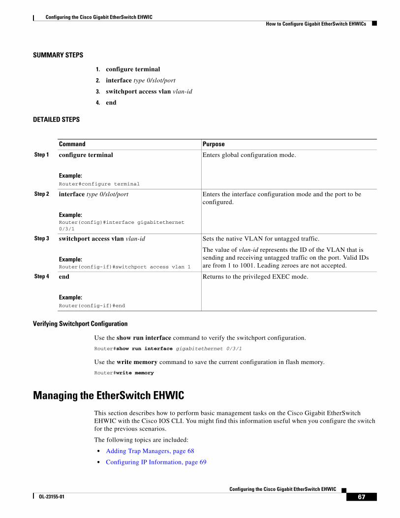
Configuring the Cisco Gigabit EtherSwitch EHWICHow to Configure Gigabit EtherSwitch EHWICs
67Configuring the Cisco Gigabit EtherSwitch EHWIC
OL-23155-01
SUMMARY STEPS
1. configure terminal
2. interface type 0/slot/port
3. switchport access vlan vlan-id
4. end
DETAILED STEPS
Verifying Switchport Configuration
Use the show run interface command to verify the switchport configuration.
Router#show run interface gigabitethernet 0/3/1
Use the write memory command to save the current configuration in flash memory.
Router#write memory
Managing the EtherSwitch EHWICThis section describes how to perform basic management tasks on the Cisco Gigabit EtherSwitch EHWIC with the Cisco IOS CLI. You might find this information useful when you configure the switch for the previous scenarios.
The following topics are included:
• Adding Trap Managers, page 68
• Configuring IP Information, page 69
Command Purpose
Step 1 configure terminal
Example:Router#configure terminal
Enters global configuration mode.
Step 2 interface type 0/slot/port
Example:Router(config)#interface gigabitethernet 0/3/1
Enters the interface configuration mode and the port to be configured.
Step 3 switchport access vlan vlan-id
Example:Router(config-if)#switchport access vlan 1
Sets the native VLAN for untagged traffic.
The value of vlan-id represents the ID of the VLAN that is sending and receiving untagged traffic on the port. Valid IDs are from 1 to 1001. Leading zeroes are not accepted.
Step 4 end
Example:Router(config-if)#end
Returns to the privileged EXEC mode.
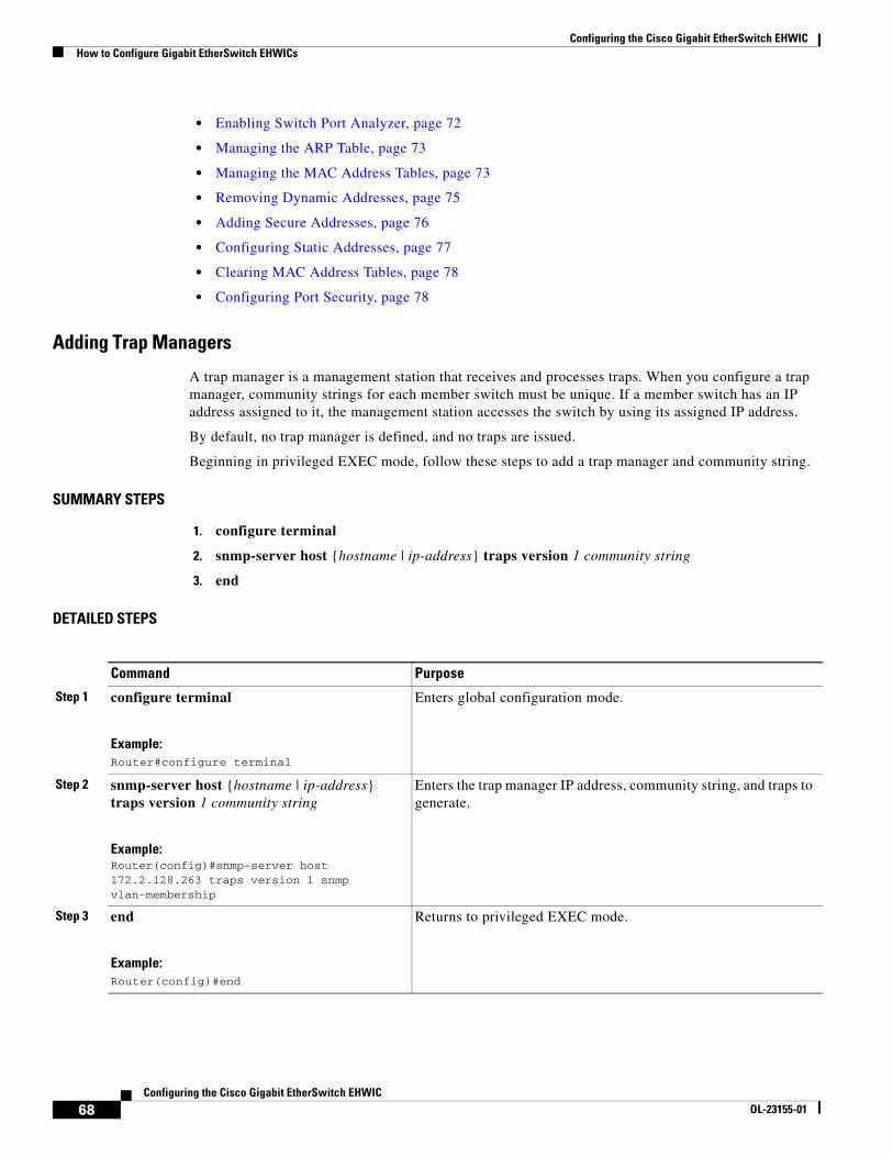
Configuring the Cisco Gigabit EtherSwitch EHWICHow to Configure Gigabit EtherSwitch EHWICs
68Configuring the Cisco Gigabit EtherSwitch EHWIC
OL-23155-01
• Enabling Switch Port Analyzer, page 72
• Managing the ARP Table, page 73
• Managing the MAC Address Tables, page 73
• Removing Dynamic Addresses, page 75
• Adding Secure Addresses, page 76
• Configuring Static Addresses, page 77
• Clearing MAC Address Tables, page 78
• Configuring Port Security, page 78
Adding Trap Managers
A trap manager is a management station that receives and processes traps. When you configure a trap manager, community strings for each member switch must be unique. If a member switch has an IP address assigned to it, the management station accesses the switch by using its assigned IP address.
By default, no trap manager is defined, and no traps are issued.
Beginning in privileged EXEC mode, follow these steps to add a trap manager and community string.
SUMMARY STEPS
1. configure terminal
2. snmp-server host {hostname | ip-address} traps version 1 community string
3. end
DETAILED STEPS
Command Purpose
Step 1 configure terminal
Example:Router#configure terminal
Enters global configuration mode.
Step 2 snmp-server host {hostname | ip-address} traps version 1 community string
Example:Router(config)#snmp-server host 172.2.128.263 traps version 1 snmp vlan-membership
Enters the trap manager IP address, community string, and traps to generate.
Step 3 end
Example:Router(config)#end
Returns to privileged EXEC mode.
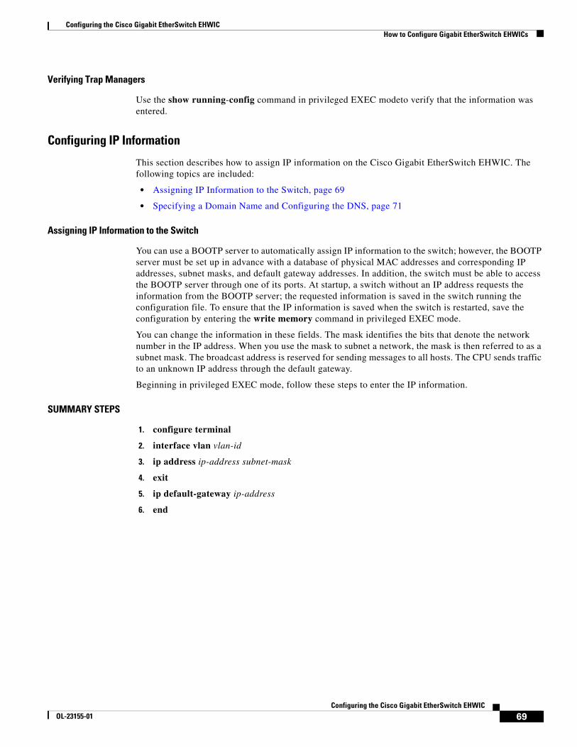
Configuring the Cisco Gigabit EtherSwitch EHWICHow to Configure Gigabit EtherSwitch EHWICs
69Configuring the Cisco Gigabit EtherSwitch EHWIC
OL-23155-01
Verifying Trap Managers
Use the show running-config command in privileged EXEC modeto verify that the information was entered.
Configuring IP Information
This section describes how to assign IP information on the Cisco Gigabit EtherSwitch EHWIC. The following topics are included:
• Assigning IP Information to the Switch, page 69
• Specifying a Domain Name and Configuring the DNS, page 71
Assigning IP Information to the Switch
You can use a BOOTP server to automatically assign IP information to the switch; however, the BOOTP server must be set up in advance with a database of physical MAC addresses and corresponding IP addresses, subnet masks, and default gateway addresses. In addition, the switch must be able to access the BOOTP server through one of its ports. At startup, a switch without an IP address requests the information from the BOOTP server; the requested information is saved in the switch running the configuration file. To ensure that the IP information is saved when the switch is restarted, save the configuration by entering the write memory command in privileged EXEC mode.
You can change the information in these fields. The mask identifies the bits that denote the network number in the IP address. When you use the mask to subnet a network, the mask is then referred to as a subnet mask. The broadcast address is reserved for sending messages to all hosts. The CPU sends traffic to an unknown IP address through the default gateway.
Beginning in privileged EXEC mode, follow these steps to enter the IP information.
SUMMARY STEPS
1. configure terminal
2. interface vlan vlan-id
3. ip address ip-address subnet-mask
4. exit
5. ip default-gateway ip-address
6. end
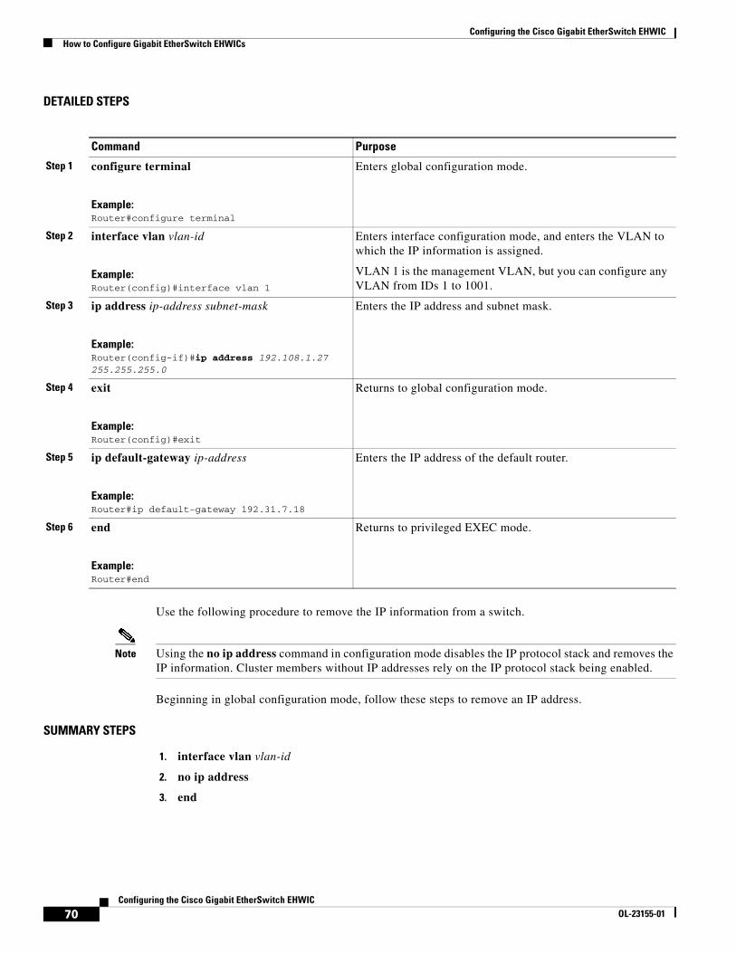
Configuring the Cisco Gigabit EtherSwitch EHWICHow to Configure Gigabit EtherSwitch EHWICs
70Configuring the Cisco Gigabit EtherSwitch EHWIC
OL-23155-01
DETAILED STEPS
Use the following procedure to remove the IP information from a switch.
Note Using the no ip address command in configuration mode disables the IP protocol stack and removes the IP information. Cluster members without IP addresses rely on the IP protocol stack being enabled.
Beginning in global configuration mode, follow these steps to remove an IP address.
SUMMARY STEPS
1. interface vlan vlan-id
2. no ip address
3. end
Command Purpose
Step 1 configure terminal
Example:Router#configure terminal
Enters global configuration mode.
Step 2 interface vlan vlan-id
Example:Router(config)#interface vlan 1
Enters interface configuration mode, and enters the VLAN to which the IP information is assigned.
VLAN 1 is the management VLAN, but you can configure any VLAN from IDs 1 to 1001.
Step 3 ip address ip-address subnet-mask
Example:Router(config-if)#ip address 192.108.1.27 255.255.255.0
Enters the IP address and subnet mask.
Step 4 exit
Example:Router(config)#exit
Returns to global configuration mode.
Step 5 ip default-gateway ip-address
Example:Router#ip default-gateway 192.31.7.18
Enters the IP address of the default router.
Step 6 end
Example:Router#end
Returns to privileged EXEC mode.
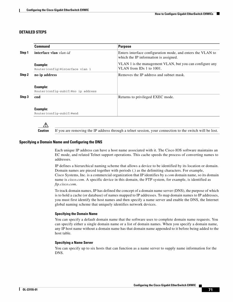
Configuring the Cisco Gigabit EtherSwitch EHWICHow to Configure Gigabit EtherSwitch EHWICs
71Configuring the Cisco Gigabit EtherSwitch EHWIC
OL-23155-01
DETAILED STEPS
Caution If you are removing the IP address through a telnet session, your connection to the switch will be lost.
Specifying a Domain Name and Configuring the DNS
Each unique IP address can have a host name associated with it. The Cisco IOS software maintains an EC mode, and related Telnet support operations. This cache speeds the process of converting names to addresses.
IP defines a hierarchical naming scheme that allows a device to be identified by its location or domain. Domain names are pieced together with periods (.) as the delimiting characters. For example, Cisco Systems, Inc. is a commercial organization that IP identifies by a com domain name, so its domain name is cisco.com. A specific device in this domain, the FTP system, for example, is identified as ftp.cisco.com.
To track domain names, IP has defined the concept of a domain name server (DNS), the purpose of which is to hold a cache (or database) of names mapped to IP addresses. To map domain names to IP addresses, you must first identify the host names and then specify a name server and enable the DNS, the Internet global naming scheme that uniquely identifies network devices.
Specifying the Domain Name
You can specify a default domain name that the software uses to complete domain name requests. You can specify either a single domain name or a list of domain names. When you specify a domain name, any IP host name without a domain name has that domain name appended to it before being added to the host table.
Specifying a Name Server
You can specify up to six hosts that can function as a name server to supply name information for the DNS.
Command Purpose
Step 1 interface vlan vlan-id
Example:Router(config)#interface vlan 1
Enters interface configuration mode, and enters the VLAN to which the IP information is assigned.
VLAN 1 is the management VLAN, but you can configure any VLAN from IDs 1 to 1001.
Step 2 no ip address
Example:Router(config-subif)#no ip address
Removes the IP address and subnet mask.
Step 3 end
Example:Router(config-subif)#end
Returns to privileged EXEC mode.
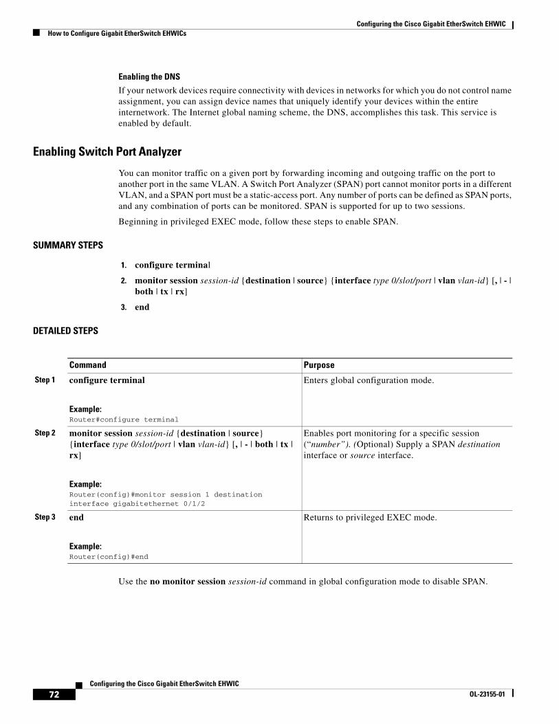
Configuring the Cisco Gigabit EtherSwitch EHWICHow to Configure Gigabit EtherSwitch EHWICs
72Configuring the Cisco Gigabit EtherSwitch EHWIC
OL-23155-01
Enabling the DNS
If your network devices require connectivity with devices in networks for which you do not control name assignment, you can assign device names that uniquely identify your devices within the entire internetwork. The Internet global naming scheme, the DNS, accomplishes this task. This service is enabled by default.
Enabling Switch Port Analyzer
You can monitor traffic on a given port by forwarding incoming and outgoing traffic on the port to another port in the same VLAN. A Switch Port Analyzer (SPAN) port cannot monitor ports in a different VLAN, and a SPAN port must be a static-access port. Any number of ports can be defined as SPAN ports, and any combination of ports can be monitored. SPAN is supported for up to two sessions.
Beginning in privileged EXEC mode, follow these steps to enable SPAN.
SUMMARY STEPS
1. configure terminal
2. monitor session session-id {destination | source} {interface type 0/slot/port | vlan vlan-id} [, | - | both | tx | rx]
3. end
DETAILED STEPS
Use the no monitor session session-id command in global configuration mode to disable SPAN.
Command Purpose
Step 1 configure terminal
Example:Router#configure terminal
Enters global configuration mode.
Step 2 monitor session session-id {destination | source} {interface type 0/slot/port | vlan vlan-id} [, | - | both | tx | rx]
Example:Router(config)#monitor session 1 destination interface gigabitethernet 0/1/2
Enables port monitoring for a specific session (“number”). (Optional) Supply a SPAN destination interface or source interface.
Step 3 end
Example:Router(config)#end
Returns to privileged EXEC mode.
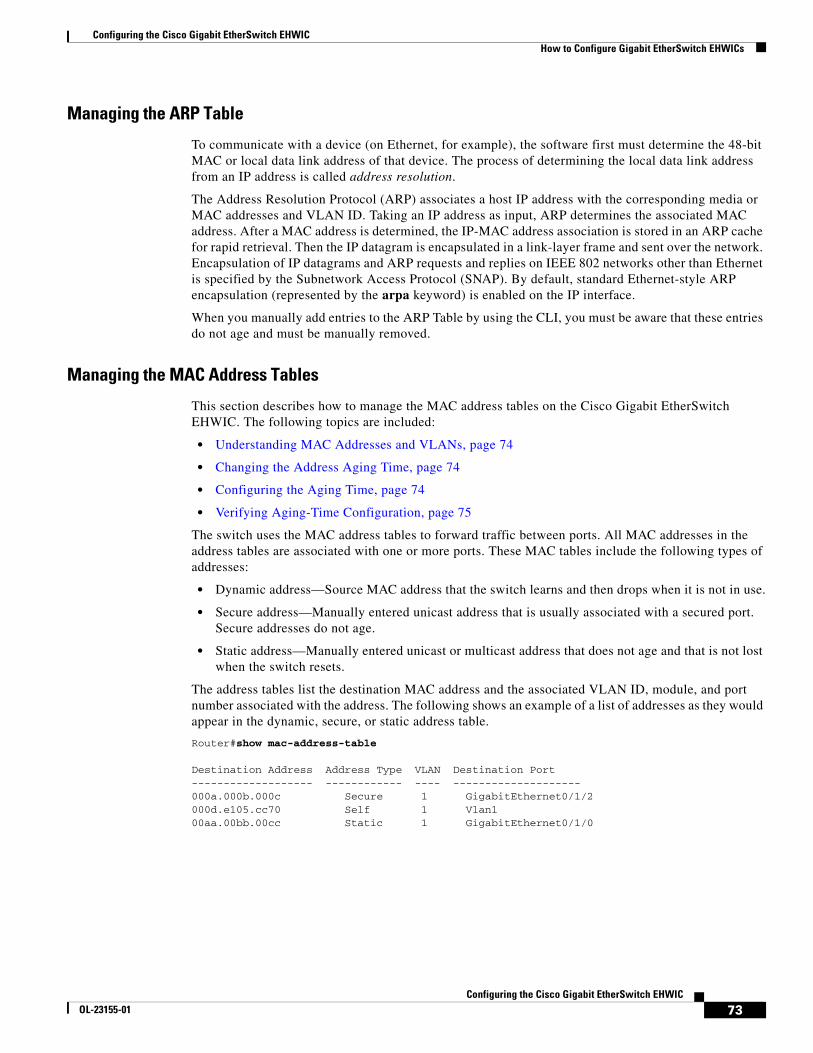
Configuring the Cisco Gigabit EtherSwitch EHWICHow to Configure Gigabit EtherSwitch EHWICs
73Configuring the Cisco Gigabit EtherSwitch EHWIC
OL-23155-01
Managing the ARP Table
To communicate with a device (on Ethernet, for example), the software first must determine the 48-bit MAC or local data link address of that device. The process of determining the local data link address from an IP address is called address resolution.
The Address Resolution Protocol (ARP) associates a host IP address with the corresponding media or MAC addresses and VLAN ID. Taking an IP address as input, ARP determines the associated MAC address. After a MAC address is determined, the IP-MAC address association is stored in an ARP cache for rapid retrieval. Then the IP datagram is encapsulated in a link-layer frame and sent over the network. Encapsulation of IP datagrams and ARP requests and replies on IEEE 802 networks other than Ethernet is specified by the Subnetwork Access Protocol (SNAP). By default, standard Ethernet-style ARP encapsulation (represented by the arpa keyword) is enabled on the IP interface.
When you manually add entries to the ARP Table by using the CLI, you must be aware that these entries do not age and must be manually removed.
Managing the MAC Address Tables
This section describes how to manage the MAC address tables on the Cisco Gigabit EtherSwitch EHWIC. The following topics are included:
• Understanding MAC Addresses and VLANs, page 74
• Changing the Address Aging Time, page 74
• Configuring the Aging Time, page 74
• Verifying Aging-Time Configuration, page 75
The switch uses the MAC address tables to forward traffic between ports. All MAC addresses in the address tables are associated with one or more ports. These MAC tables include the following types of addresses:
• Dynamic address—Source MAC address that the switch learns and then drops when it is not in use.
• Secure address—Manually entered unicast address that is usually associated with a secured port. Secure addresses do not age.
• Static address—Manually entered unicast or multicast address that does not age and that is not lost when the switch resets.
The address tables list the destination MAC address and the associated VLAN ID, module, and port number associated with the address. The following shows an example of a list of addresses as they would appear in the dynamic, secure, or static address table.
Router#show mac-address-table
Destination Address Address Type VLAN Destination Port------------------- ------------ ---- --------------------000a.000b.000c Secure 1 GigabitEthernet0/1/2000d.e105.cc70 Self 1 Vlan100aa.00bb.00cc Static 1 GigabitEthernet0/1/0
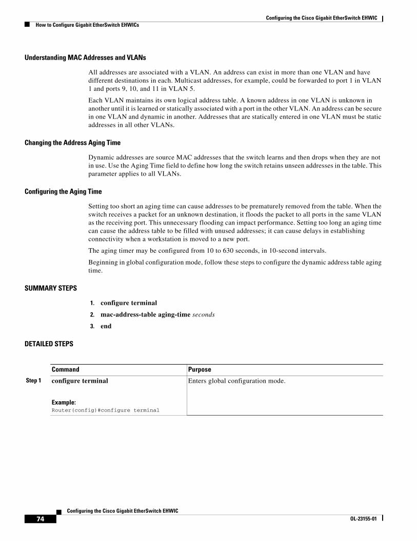
Configuring the Cisco Gigabit EtherSwitch EHWICHow to Configure Gigabit EtherSwitch EHWICs
74Configuring the Cisco Gigabit EtherSwitch EHWIC
OL-23155-01
Understanding MAC Addresses and VLANs
All addresses are associated with a VLAN. An address can exist in more than one VLAN and have different destinations in each. Multicast addresses, for example, could be forwarded to port 1 in VLAN 1 and ports 9, 10, and 11 in VLAN 5.
Each VLAN maintains its own logical address table. A known address in one VLAN is unknown in another until it is learned or statically associated with a port in the other VLAN. An address can be secure in one VLAN and dynamic in another. Addresses that are statically entered in one VLAN must be static addresses in all other VLANs.
Changing the Address Aging Time
Dynamic addresses are source MAC addresses that the switch learns and then drops when they are not in use. Use the Aging Time field to define how long the switch retains unseen addresses in the table. This parameter applies to all VLANs.
Configuring the Aging Time
Setting too short an aging time can cause addresses to be prematurely removed from the table. When the switch receives a packet for an unknown destination, it floods the packet to all ports in the same VLAN as the receiving port. This unnecessary flooding can impact performance. Setting too long an aging time can cause the address table to be filled with unused addresses; it can cause delays in establishing connectivity when a workstation is moved to a new port.
The aging timer may be configured from 10 to 630 seconds, in 10-second intervals.
Beginning in global configuration mode, follow these steps to configure the dynamic address table aging time.
SUMMARY STEPS
1. configure terminal
2. mac-address-table aging-time seconds
3. end
DETAILED STEPS
Command Purpose
Step 1 configure terminal
Example:Router(config)#configure terminal
Enters global configuration mode.
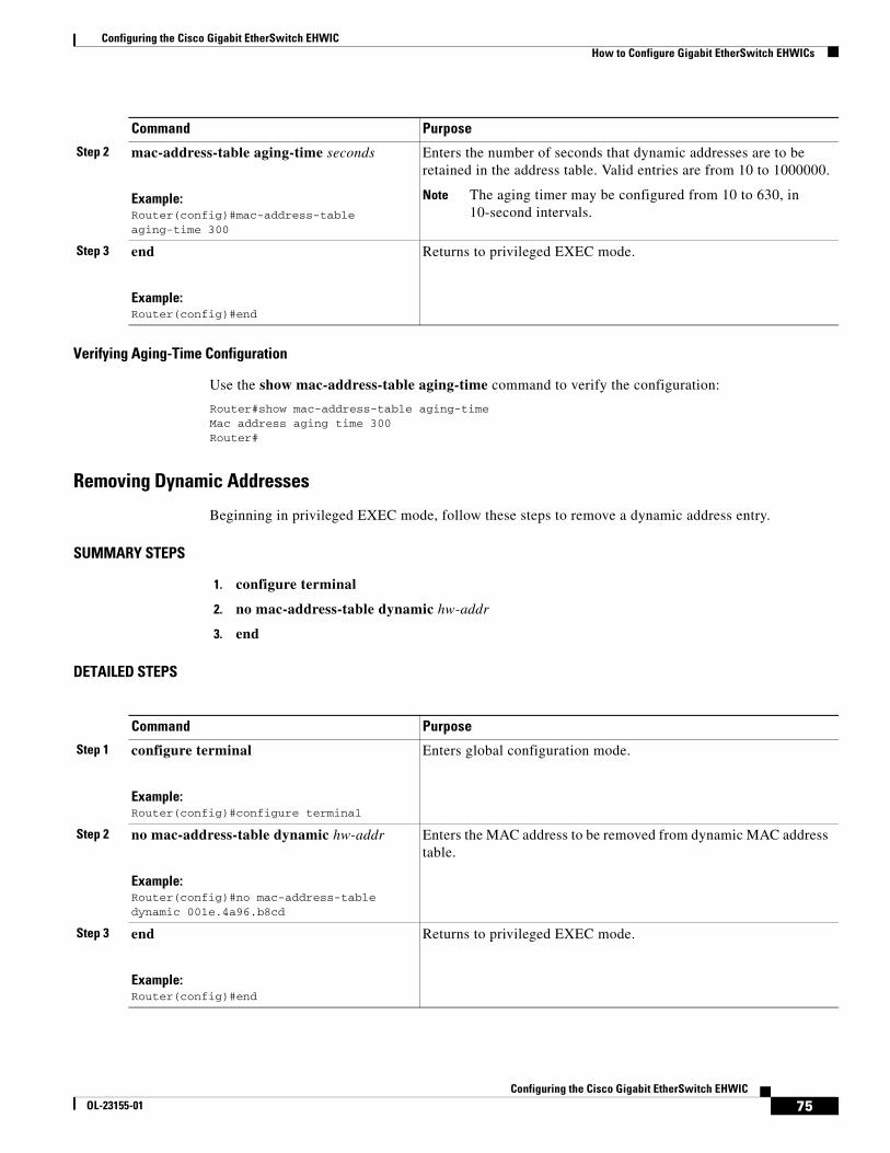
Configuring the Cisco Gigabit EtherSwitch EHWICHow to Configure Gigabit EtherSwitch EHWICs
75Configuring the Cisco Gigabit EtherSwitch EHWIC
OL-23155-01
Verifying Aging-Time Configuration
Use the show mac-address-table aging-time command to verify the configuration:
Router#show mac-address-table aging-timeMac address aging time 300Router#
Removing Dynamic Addresses
Beginning in privileged EXEC mode, follow these steps to remove a dynamic address entry.
SUMMARY STEPS
1. configure terminal
2. no mac-address-table dynamic hw-addr
3. end
DETAILED STEPS
Step 2 mac-address-table aging-time seconds
Example:Router(config)#mac-address-table aging-time 300
Enters the number of seconds that dynamic addresses are to be retained in the address table. Valid entries are from 10 to 1000000.
Note The aging timer may be configured from 10 to 630, in 10-second intervals.
Step 3 end
Example:Router(config)#end
Returns to privileged EXEC mode.
Command Purpose
Command Purpose
Step 1 configure terminal
Example:Router(config)#configure terminal
Enters global configuration mode.
Step 2 no mac-address-table dynamic hw-addr
Example:Router(config)#no mac-address-table dynamic 001e.4a96.b8cd
Enters the MAC address to be removed from dynamic MAC address table.
Step 3 end
Example:Router(config)#end
Returns to privileged EXEC mode.
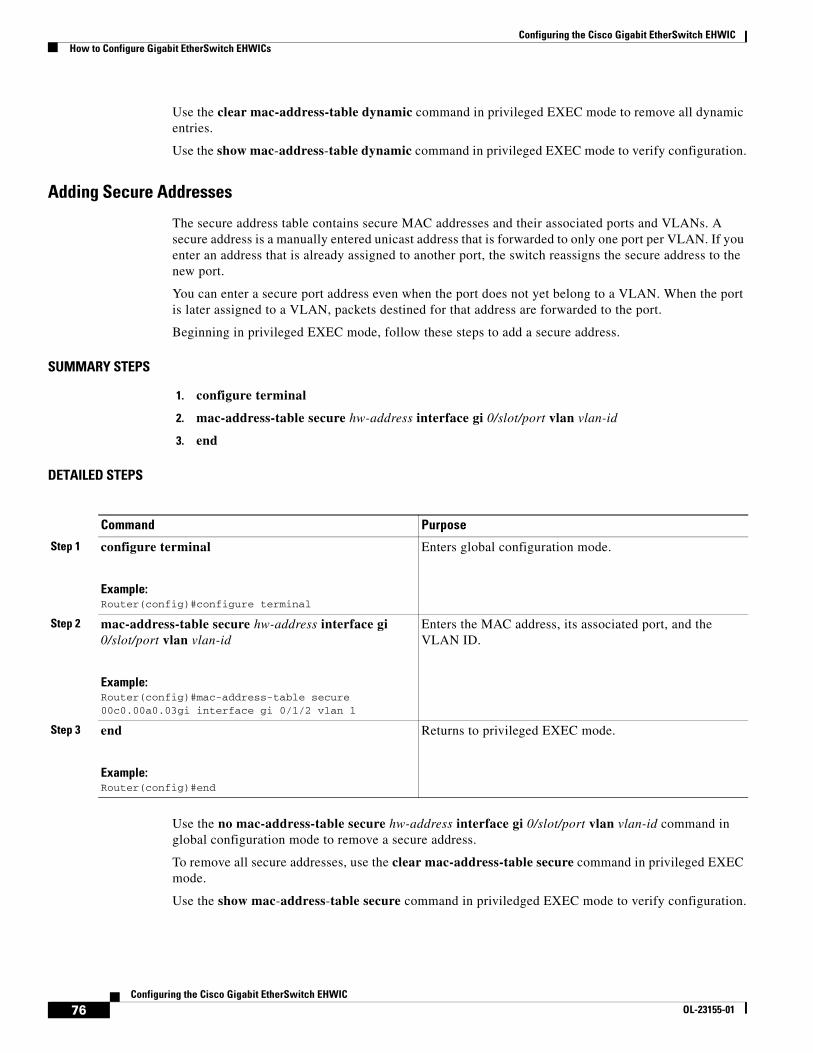
Configuring the Cisco Gigabit EtherSwitch EHWICHow to Configure Gigabit EtherSwitch EHWICs
76Configuring the Cisco Gigabit EtherSwitch EHWIC
OL-23155-01
Use the clear mac-address-table dynamic command in privileged EXEC mode to remove all dynamic entries.
Use the show mac-address-table dynamic command in privileged EXEC mode to verify configuration.
Adding Secure Addresses
The secure address table contains secure MAC addresses and their associated ports and VLANs. A secure address is a manually entered unicast address that is forwarded to only one port per VLAN. If you enter an address that is already assigned to another port, the switch reassigns the secure address to the new port.
You can enter a secure port address even when the port does not yet belong to a VLAN. When the port is later assigned to a VLAN, packets destined for that address are forwarded to the port.
Beginning in privileged EXEC mode, follow these steps to add a secure address.
SUMMARY STEPS
1. configure terminal
2. mac-address-table secure hw-address interface gi 0/slot/port vlan vlan-id
3. end
DETAILED STEPS
Use the no mac-address-table secure hw-address interface gi 0/slot/port vlan vlan-id command in global configuration mode to remove a secure address.
To remove all secure addresses, use the clear mac-address-table secure command in privileged EXEC mode.
Use the show mac-address-table secure command in priviledged EXEC mode to verify configuration.
Command Purpose
Step 1 configure terminal
Example:Router(config)#configure terminal
Enters global configuration mode.
Step 2 mac-address-table secure hw-address interface gi 0/slot/port vlan vlan-id
Example:Router(config)#mac-address-table secure 00c0.00a0.03gi interface gi 0/1/2 vlan 1
Enters the MAC address, its associated port, and the VLAN ID.
Step 3 end
Example:Router(config)#end
Returns to privileged EXEC mode.
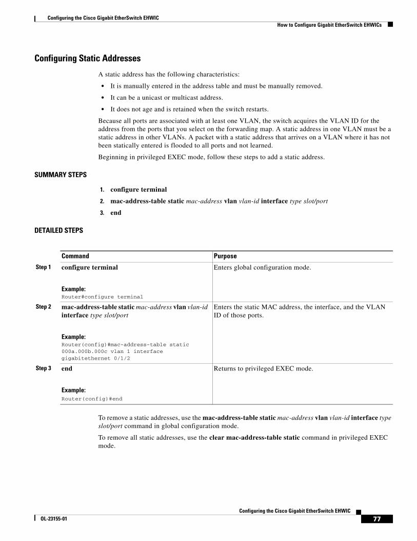
Configuring the Cisco Gigabit EtherSwitch EHWICHow to Configure Gigabit EtherSwitch EHWICs
77Configuring the Cisco Gigabit EtherSwitch EHWIC
OL-23155-01
Configuring Static Addresses
A static address has the following characteristics:
• It is manually entered in the address table and must be manually removed.
• It can be a unicast or multicast address.
• It does not age and is retained when the switch restarts.
Because all ports are associated with at least one VLAN, the switch acquires the VLAN ID for the address from the ports that you select on the forwarding map. A static address in one VLAN must be a static address in other VLANs. A packet with a static address that arrives on a VLAN where it has not been statically entered is flooded to all ports and not learned.
Beginning in privileged EXEC mode, follow these steps to add a static address.
SUMMARY STEPS
1. configure terminal
2. mac-address-table static mac-address vlan vlan-id interface type slot/port
3. end
DETAILED STEPS
To remove a static addresses, use the mac-address-table static mac-address vlan vlan-id interface type slot/port command in global configuration mode.
To remove all static addresses, use the clear mac-address-table static command in privileged EXEC mode.
Command Purpose
Step 1 configure terminal
Example:Router#configure terminal
Enters global configuration mode.
Step 2 mac-address-table static mac-address vlan vlan-id interface type slot/port
Example:Router(config)#mac-address-table static 000a.000b.000c vlan 1 interface gigabitethernet 0/1/2
Enters the static MAC address, the interface, and the VLAN ID of those ports.
Step 3 end
Example:Router(config)#end
Returns to privileged EXEC mode.
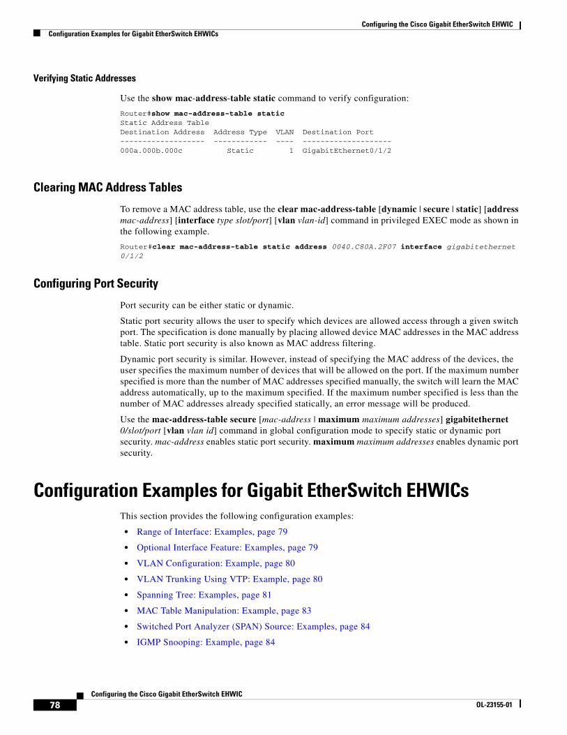
Configuring the Cisco Gigabit EtherSwitch EHWICConfiguration Examples for Gigabit EtherSwitch EHWICs
78Configuring the Cisco Gigabit EtherSwitch EHWIC
OL-23155-01
Verifying Static Addresses
Use the show mac-address-table static command to verify configuration:
Router#show mac-address-table staticStatic Address TableDestination Address Address Type VLAN Destination Port------------------- ------------ ---- --------------------000a.000b.000c Static 1 GigabitEthernet0/1/2
Clearing MAC Address Tables
To remove a MAC address table, use the clear mac-address-table [dynamic | secure | static] [address mac-address] [interface type slot/port] [vlan vlan-id] command in privileged EXEC mode as shown in the following example.
Router#clear mac-address-table static address 0040.C80A.2F07 interface gigabitethernet 0/1/2
Configuring Port Security
Port security can be either static or dynamic.
Static port security allows the user to specify which devices are allowed access through a given switch port. The specification is done manually by placing allowed device MAC addresses in the MAC address table. Static port security is also known as MAC address filtering.
Dynamic port security is similar. However, instead of specifying the MAC address of the devices, the user specifies the maximum number of devices that will be allowed on the port. If the maximum number specified is more than the number of MAC addresses specified manually, the switch will learn the MAC address automatically, up to the maximum specified. If the maximum number specified is less than the number of MAC addresses already specified statically, an error message will be produced.
Use the mac-address-table secure [mac-address | maximum maximum addresses] gigabitethernet 0/slot/port [vlan vlan id] command in global configuration mode to specify static or dynamic port security. mac-address enables static port security. maximum maximum addresses enables dynamic port security.
Configuration Examples for Gigabit EtherSwitch EHWICsThis section provides the following configuration examples:
• Range of Interface: Examples, page 79
• Optional Interface Feature: Examples, page 79
• VLAN Configuration: Example, page 80
• VLAN Trunking Using VTP: Example, page 80
• Spanning Tree: Examples, page 81
• MAC Table Manipulation: Example, page 83
• Switched Port Analyzer (SPAN) Source: Examples, page 84
• IGMP Snooping: Example, page 84
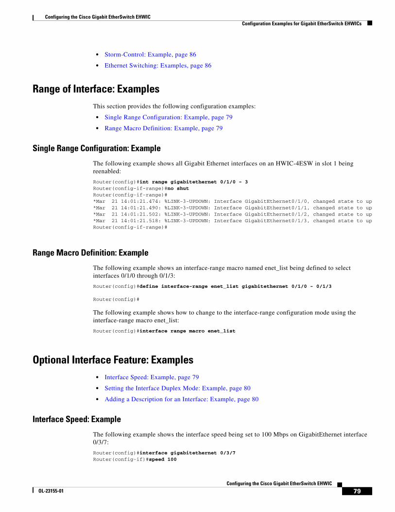
Configuring the Cisco Gigabit EtherSwitch EHWICConfiguration Examples for Gigabit EtherSwitch EHWICs
79Configuring the Cisco Gigabit EtherSwitch EHWIC
OL-23155-01
• Storm-Control: Example, page 86
• Ethernet Switching: Examples, page 86
Range of Interface: ExamplesThis section provides the following configuration examples:
• Single Range Configuration: Example, page 79
• Range Macro Definition: Example, page 79
Single Range Configuration: Example
The following example shows all Gigabit Ethernet interfaces on an HWIC-4ESW in slot 1 being reenabled:
Router(config)#int range gigabitethernet 0/1/0 - 3Router(config-if-range)#no shutRouter(config-if-range)#*Mar 21 14:01:21.474: %LINK-3-UPDOWN: Interface GigabitEthernet0/1/0, changed state to up*Mar 21 14:01:21.490: %LINK-3-UPDOWN: Interface GigabitEthernet0/1/1, changed state to up*Mar 21 14:01:21.502: %LINK-3-UPDOWN: Interface GigabitEthernet0/1/2, changed state to up*Mar 21 14:01:21.518: %LINK-3-UPDOWN: Interface GigabitEthernet0/1/3, changed state to upRouter(config-if-range)#
Range Macro Definition: Example
The following example shows an interface-range macro named enet_list being defined to select interfaces 0/1/0 through 0/1/3:
Router(config)#define interface-range enet_list gigabitethernet 0/1/0 - 0/1/3
Router(config)#
The following example shows how to change to the interface-range configuration mode using the interface-range macro enet_list:
Router(config)#interface range macro enet_list
Optional Interface Feature: Examples• Interface Speed: Example, page 79
• Setting the Interface Duplex Mode: Example, page 80
• Adding a Description for an Interface: Example, page 80
Interface Speed: Example
The following example shows the interface speed being set to 100 Mbps on GigabitEthernet interface 0/3/7:
Router(config)#interface gigabitethernet 0/3/7Router(config-if)#speed 100
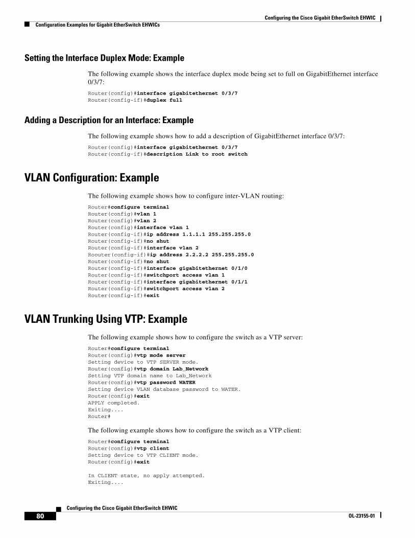
Configuring the Cisco Gigabit EtherSwitch EHWICConfiguration Examples for Gigabit EtherSwitch EHWICs
80Configuring the Cisco Gigabit EtherSwitch EHWIC
OL-23155-01
Setting the Interface Duplex Mode: Example
The following example shows the interface duplex mode being set to full on GigabitEthernet interface 0/3/7:
Router(config)#interface gigabitethernet 0/3/7Router(config-if)#duplex full
Adding a Description for an Interface: Example
The following example shows how to add a description of GigabitEthernet interface 0/3/7:
Router(config)#interface gigabitethernet 0/3/7Router(config-if)#description Link to root switch
VLAN Configuration: ExampleThe following example shows how to configure inter-VLAN routing:
Router#configure terminalRouter(config)#vlan 1Router(config)#vlan 2Router(config)#interface vlan 1Router(config-if)#ip address 1.1.1.1 255.255.255.0Router(config-if)#no shutRouter(config-if)#interface vlan 2Roouter(config-if)#ip address 2.2.2.2 255.255.255.0Router(config-if)#no shutRouter(config-if)#interface gigabitethernet 0/1/0Router(config-if)#switchport access vlan 1Router(config-if)#interface gigabitethernet 0/1/1Router(config-if)#switchport access vlan 2Router(config-if)#exit
VLAN Trunking Using VTP: ExampleThe following example shows how to configure the switch as a VTP server:
Router#configure terminalRouter(config)#vtp mode serverSetting device to VTP SERVER mode.Router(config)#vtp domain Lab_NetworkSetting VTP domain name to Lab_NetworkRouter(config)#vtp password WATERSetting device VLAN database password to WATER.Router(config)#exitAPPLY completed.Exiting....Router#
The following example shows how to configure the switch as a VTP client:
Router#configure terminalRouter(config)#vtp clientSetting device to VTP CLIENT mode.Router(config)#exit
In CLIENT state, no apply attempted.Exiting....
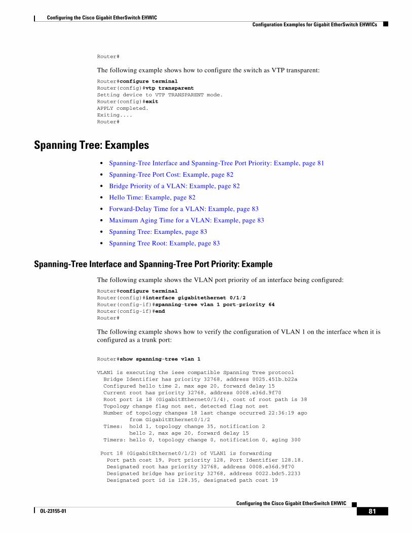
Configuring the Cisco Gigabit EtherSwitch EHWICConfiguration Examples for Gigabit EtherSwitch EHWICs
81Configuring the Cisco Gigabit EtherSwitch EHWIC
OL-23155-01
Router#
The following example shows how to configure the switch as VTP transparent:
Router#configure terminalRouter(config)#vtp transparentSetting device to VTP TRANSPARENT mode.Router(config)#exitAPPLY completed.Exiting....Router#
Spanning Tree: Examples• Spanning-Tree Interface and Spanning-Tree Port Priority: Example, page 81
• Spanning-Tree Port Cost: Example, page 82
• Bridge Priority of a VLAN: Example, page 82
• Hello Time: Example, page 82
• Forward-Delay Time for a VLAN: Example, page 83
• Maximum Aging Time for a VLAN: Example, page 83
• Spanning Tree: Examples, page 83
• Spanning Tree Root: Example, page 83
Spanning-Tree Interface and Spanning-Tree Port Priority: Example
The following example shows the VLAN port priority of an interface being configured:
Router#configure terminal Router(config)#interface gigabitethernet 0/1/2Router(config-if)#spanning-tree vlan 1 port-priority 64 Router(config-if)#end Router#
The following example shows how to verify the configuration of VLAN 1 on the interface when it is configured as a trunk port:
Router#show spanning-tree vlan 1
VLAN1 is executing the ieee compatible Spanning Tree protocol Bridge Identifier has priority 32768, address 0025.451b.b22a Configured hello time 2, max age 20, forward delay 15 Current root has priority 32768, address 0008.e36d.9f70 Root port is 18 (GigabitEthernet0/1/4), cost of root path is 38 Topology change flag not set, detected flag not set Number of topology changes 18 last change occurred 22:36:19 ago from GigabitEthernet0/1/2 Times: hold 1, topology change 35, notification 2 hello 2, max age 20, forward delay 15 Timers: hello 0, topology change 0, notification 0, aging 300
Port 18 (GigabitEthernet0/1/2) of VLAN1 is forwarding Port path cost 19, Port priority 128, Port Identifier 128.18. Designated root has priority 32768, address 0008.e36d.9f70 Designated bridge has priority 32768, address 0022.bdc5.2233 Designated port id is 128.35, designated path cost 19
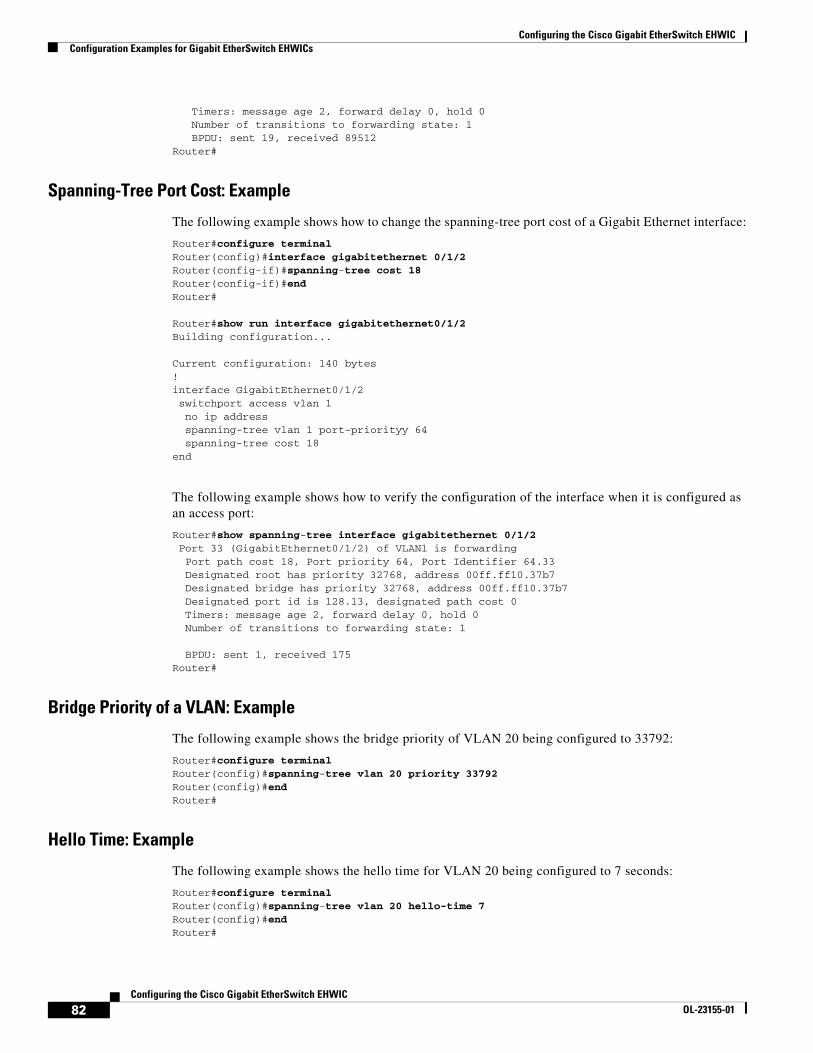
Configuring the Cisco Gigabit EtherSwitch EHWICConfiguration Examples for Gigabit EtherSwitch EHWICs
82Configuring the Cisco Gigabit EtherSwitch EHWIC
OL-23155-01
Timers: message age 2, forward delay 0, hold 0 Number of transitions to forwarding state: 1 BPDU: sent 19, received 89512Router#
Spanning-Tree Port Cost: Example
The following example shows how to change the spanning-tree port cost of a Gigabit Ethernet interface:
Router#configure terminal Router(config)#interface gigabitethernet 0/1/2Router(config-if)#spanning-tree cost 18 Router(config-if)#end Router#
Router#show run interface gigabitethernet0/1/2Building configuration...
Current configuration: 140 bytes!interface GigabitEthernet0/1/2 switchport access vlan 1 no ip address spanning-tree vlan 1 port-priorityy 64 spanning-tree cost 18end
The following example shows how to verify the configuration of the interface when it is configured as an access port:
Router#show spanning-tree interface gigabitethernet 0/1/2 Port 33 (GigabitEthernet0/1/2) of VLAN1 is forwarding Port path cost 18, Port priority 64, Port Identifier 64.33 Designated root has priority 32768, address 00ff.ff10.37b7 Designated bridge has priority 32768, address 00ff.ff10.37b7 Designated port id is 128.13, designated path cost 0 Timers: message age 2, forward delay 0, hold 0 Number of transitions to forwarding state: 1
BPDU: sent 1, received 175Router#
Bridge Priority of a VLAN: Example
The following example shows the bridge priority of VLAN 20 being configured to 33792:
Router#configure terminal Router(config)#spanning-tree vlan 20 priority 33792 Router(config)#end Router#
Hello Time: Example
The following example shows the hello time for VLAN 20 being configured to 7 seconds:
Router#configure terminal Router(config)#spanning-tree vlan 20 hello-time 7 Router(config)#end Router#
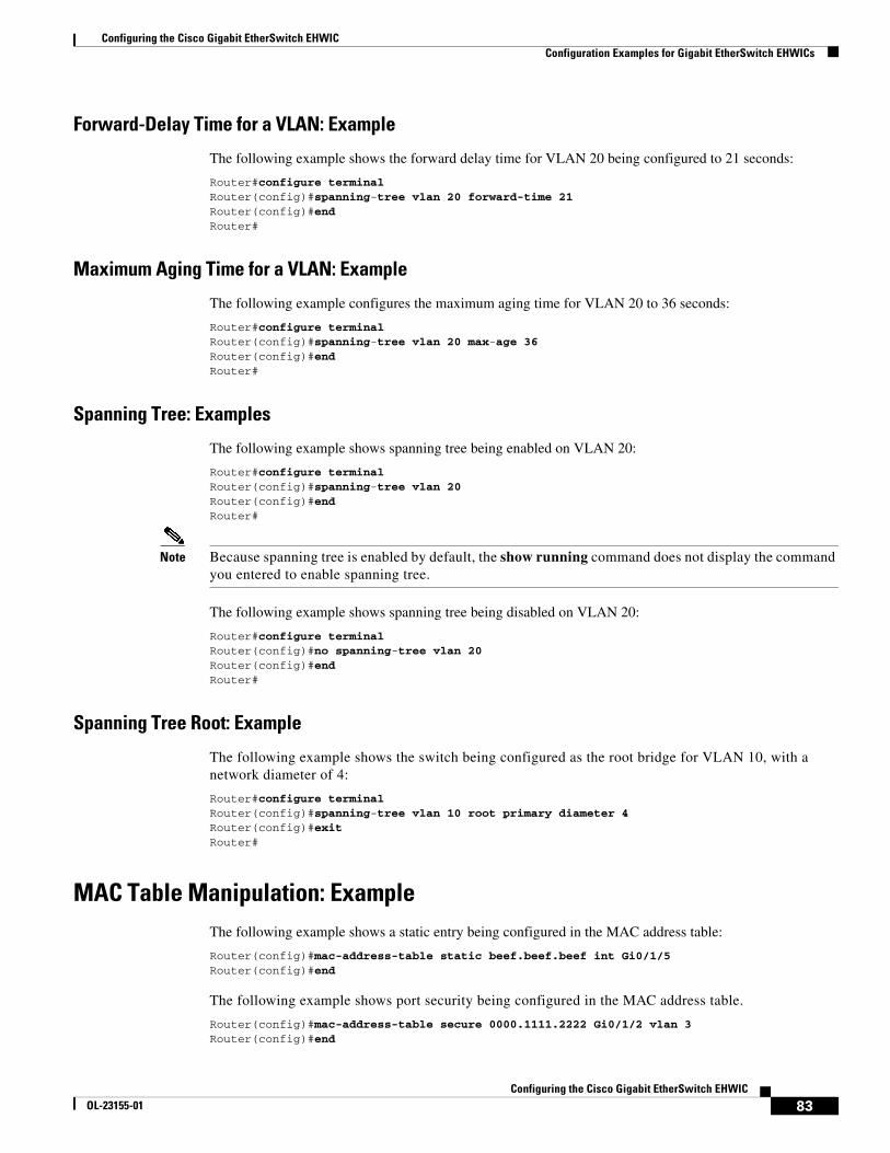
Configuring the Cisco Gigabit EtherSwitch EHWICConfiguration Examples for Gigabit EtherSwitch EHWICs
83Configuring the Cisco Gigabit EtherSwitch EHWIC
OL-23155-01
Forward-Delay Time for a VLAN: Example
The following example shows the forward delay time for VLAN 20 being configured to 21 seconds:
Router#configure terminal Router(config)#spanning-tree vlan 20 forward-time 21 Router(config)#end Router#
Maximum Aging Time for a VLAN: Example
The following example configures the maximum aging time for VLAN 20 to 36 seconds:
Router#configure terminal Router(config)#spanning-tree vlan 20 max-age 36 Router(config)#end Router#
Spanning Tree: Examples
The following example shows spanning tree being enabled on VLAN 20:
Router#configure terminal Router(config)#spanning-tree vlan 20 Router(config)#end Router#
Note Because spanning tree is enabled by default, the show running command does not display the command you entered to enable spanning tree.
The following example shows spanning tree being disabled on VLAN 20:
Router#configure terminal Router(config)#no spanning-tree vlan 20 Router(config)#end Router#
Spanning Tree Root: Example
The following example shows the switch being configured as the root bridge for VLAN 10, with a network diameter of 4:
Router#configure terminal Router(config)#spanning-tree vlan 10 root primary diameter 4 Router(config)#exit Router#
MAC Table Manipulation: ExampleThe following example shows a static entry being configured in the MAC address table:
Router(config)#mac-address-table static beef.beef.beef int Gi0/1/5Router(config)#end
The following example shows port security being configured in the MAC address table.
Router(config)#mac-address-table secure 0000.1111.2222 Gi0/1/2 vlan 3Router(config)#end
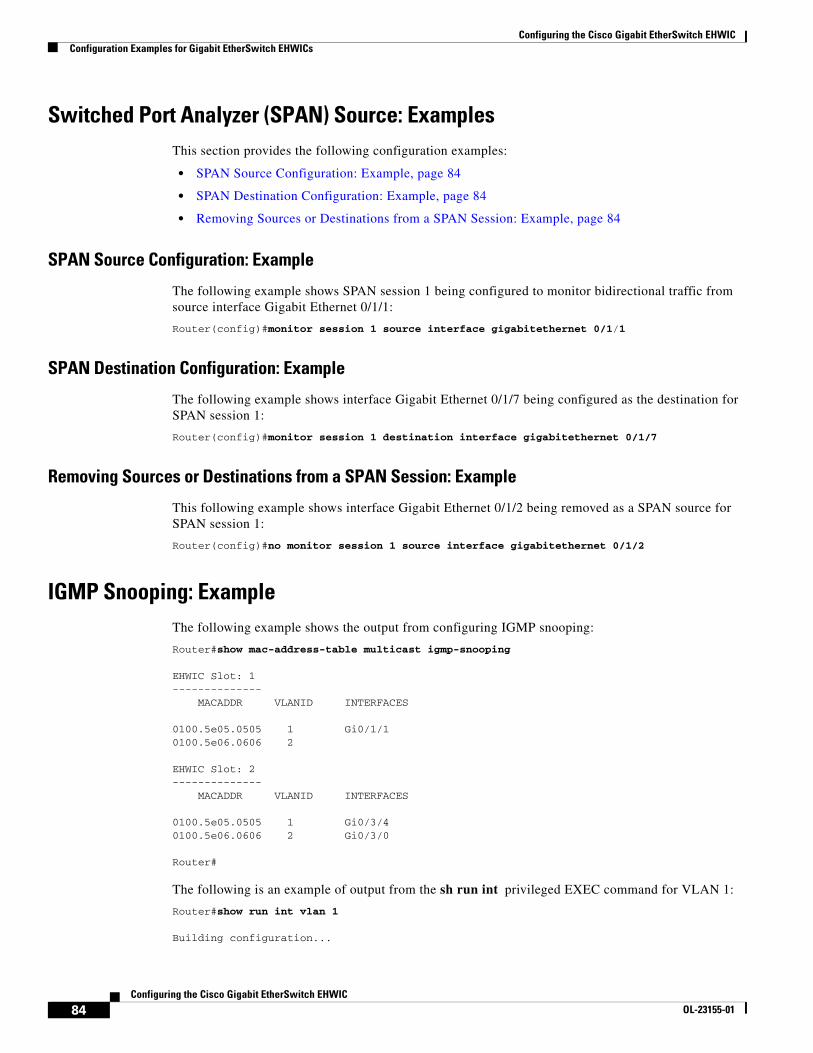
Configuring the Cisco Gigabit EtherSwitch EHWICConfiguration Examples for Gigabit EtherSwitch EHWICs
84Configuring the Cisco Gigabit EtherSwitch EHWIC
OL-23155-01
Switched Port Analyzer (SPAN) Source: ExamplesThis section provides the following configuration examples:
• SPAN Source Configuration: Example, page 84
• SPAN Destination Configuration: Example, page 84
• Removing Sources or Destinations from a SPAN Session: Example, page 84
SPAN Source Configuration: Example
The following example shows SPAN session 1 being configured to monitor bidirectional traffic from source interface Gigabit Ethernet 0/1/1:
Router(config)#monitor session 1 source interface gigabitethernet 0/1/1
SPAN Destination Configuration: Example
The following example shows interface Gigabit Ethernet 0/1/7 being configured as the destination for SPAN session 1:
Router(config)#monitor session 1 destination interface gigabitethernet 0/1/7
Removing Sources or Destinations from a SPAN Session: Example
This following example shows interface Gigabit Ethernet 0/1/2 being removed as a SPAN source for SPAN session 1:
Router(config)#no monitor session 1 source interface gigabitethernet 0/1/2
IGMP Snooping: ExampleThe following example shows the output from configuring IGMP snooping:
Router#show mac-address-table multicast igmp-snooping
EHWIC Slot: 1 -------------- MACADDR VLANID INTERFACES
0100.5e05.0505 1 Gi0/1/10100.5e06.0606 2
EHWIC Slot: 2-------------- MACADDR VLANID INTERFACES
0100.5e05.0505 1 Gi0/3/40100.5e06.0606 2 Gi0/3/0
Router#
The following is an example of output from the sh run int privileged EXEC command for VLAN 1:
Router#show run int vlan 1
Building configuration...
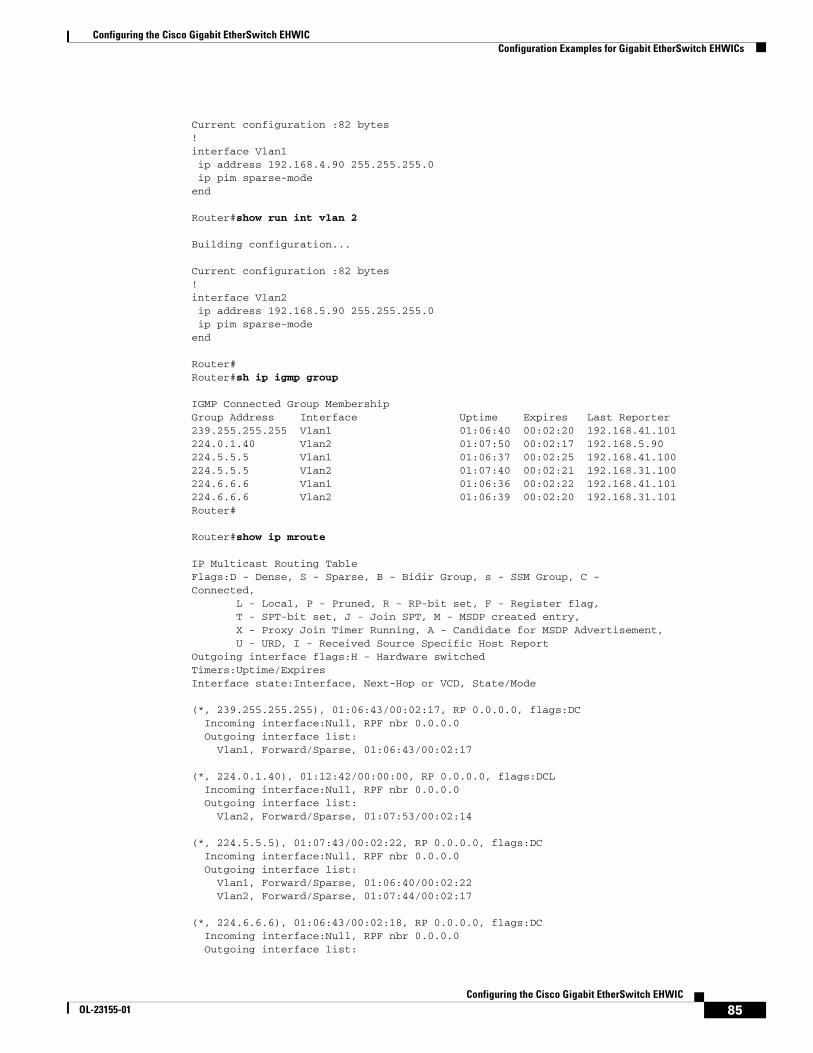
Configuring the Cisco Gigabit EtherSwitch EHWICConfiguration Examples for Gigabit EtherSwitch EHWICs
85Configuring the Cisco Gigabit EtherSwitch EHWIC
OL-23155-01
Current configuration :82 bytes ! interface Vlan1 ip address 192.168.4.90 255.255.255.0 ip pim sparse-mode end
Router#show run int vlan 2
Building configuration...
Current configuration :82 bytes ! interface Vlan2 ip address 192.168.5.90 255.255.255.0 ip pim sparse-mode end
Router# Router#sh ip igmp group
IGMP Connected Group Membership Group Address Interface Uptime Expires Last Reporter 239.255.255.255 Vlan1 01:06:40 00:02:20 192.168.41.101 224.0.1.40 Vlan2 01:07:50 00:02:17 192.168.5.90 224.5.5.5 Vlan1 01:06:37 00:02:25 192.168.41.100 224.5.5.5 Vlan2 01:07:40 00:02:21 192.168.31.100 224.6.6.6 Vlan1 01:06:36 00:02:22 192.168.41.101 224.6.6.6 Vlan2 01:06:39 00:02:20 192.168.31.101 Router#
Router#show ip mroute
IP Multicast Routing Table Flags:D - Dense, S - Sparse, B - Bidir Group, s - SSM Group, C - Connected, L - Local, P - Pruned, R - RP-bit set, F - Register flag, T - SPT-bit set, J - Join SPT, M - MSDP created entry, X - Proxy Join Timer Running, A - Candidate for MSDP Advertisement, U - URD, I - Received Source Specific Host Report Outgoing interface flags:H - Hardware switched Timers:Uptime/Expires Interface state:Interface, Next-Hop or VCD, State/Mode
(*, 239.255.255.255), 01:06:43/00:02:17, RP 0.0.0.0, flags:DC Incoming interface:Null, RPF nbr 0.0.0.0 Outgoing interface list: Vlan1, Forward/Sparse, 01:06:43/00:02:17
(*, 224.0.1.40), 01:12:42/00:00:00, RP 0.0.0.0, flags:DCL Incoming interface:Null, RPF nbr 0.0.0.0 Outgoing interface list: Vlan2, Forward/Sparse, 01:07:53/00:02:14
(*, 224.5.5.5), 01:07:43/00:02:22, RP 0.0.0.0, flags:DC Incoming interface:Null, RPF nbr 0.0.0.0 Outgoing interface list: Vlan1, Forward/Sparse, 01:06:40/00:02:22 Vlan2, Forward/Sparse, 01:07:44/00:02:17
(*, 224.6.6.6), 01:06:43/00:02:18, RP 0.0.0.0, flags:DC Incoming interface:Null, RPF nbr 0.0.0.0 Outgoing interface list:
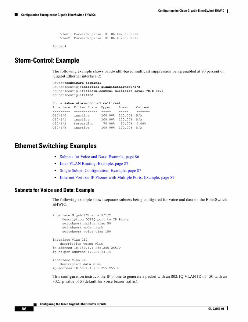
Configuring the Cisco Gigabit EtherSwitch EHWICConfiguration Examples for Gigabit EtherSwitch EHWICs
86Configuring the Cisco Gigabit EtherSwitch EHWIC
OL-23155-01
Vlan1, Forward/Sparse, 01:06:40/00:02:18 Vlan2, Forward/Sparse, 01:06:43/00:02:16
Router#
Storm-Control: ExampleThe following example shows bandwidth-based multicast suppression being enabled at 70 percent on Gigabit Ethernet interface 2:
Router#configure terminalRouter(config)#interface gigabitethernet0/1/2Router(config-if)#storm-control multicast level 70.0 30.0Router(config-if)#end
Router#show storm-control multicastInterface Filter State Upper Lower Current--------- ------------ ----- ----- -------Gi0/1/0 inactive 100.00% 100.00% N/AGi0/1/1 inactive 100.00% 100.00% N/AGi0/1/2 Forwarding 70.00% 30.00% 0.00%Gi0/1/3 inactive 100.00% 100.00% N/A
Ethernet Switching: Examples• Subnets for Voice and Data: Example, page 86
• Inter-VLAN Routing: Example, page 87
• Single Subnet Configuration: Example, page 87
• Ethernet Ports on IP Phones with Multiple Ports: Example, page 87
Subnets for Voice and Data: Example
The following example shows separate subnets being configured for voice and data on the EtherSwitch EHWIC:
interface GigabitEthernet0/1/2 description DOT1Q port to IP Phone switchport native vlan 50 switchport mode trunk switchport voice vlan 150
interface Vlan 150description voice vlan
ip address 10.150.1.1 255.255.255.0ip helper-address 172.20.73.14
interface Vlan 50description data vlan
ip address 10.50.1.1 255.255.255.0
This configuration instructs the IP phone to generate a packet with an 802.1Q VLAN ID of 150 with an 802.1p value of 5 (default for voice bearer traffic).
Configuring the Cisco Gigabit EtherSwitch EHWICConfiguration Examples for Gigabit EtherSwitch EHWICs
87Configuring the Cisco Gigabit EtherSwitch EHWIC
OL-23155-01
Note In a centralized CallManager deployment model, the DHCP server might be located across the WAN link. If so, an ip helper-address command pointing to the DHCP server should be included on the voice VLAN interface for the IP phone. This is done to obtain its IP address as well as the address of the TFTP server required for its configuration.
Be aware that IOS supports a DHCP server function. If this function is used, the EtherSwitch EHWIC serves as a local DHCP server and a helper address would not be required.
Inter-VLAN Routing: Example
Configuring inter-vlan routing is identical to the configuration on an EtherSwitch EHWIC with an MSFC. Configuring an interface for WAN routing is consistent with other IOS platforms.
The following example provides a sample configuration:
interface Vlan 160 description voice vlan ip address 10.6.1.1 255.255.255.0
interface Vlan 60description data vlan
ip address 10.60.1.1 255.255.255.0
interface Serial0/3/0ip address 160.3.1.2 255.255.255.0
Note Standard IGP routing protocols such as RIP, IGRP, EIGRP, and OSPF are supported on the EtherSwitch EHWIC. Multicast routing is also supported for PIM dense mode, sparse mode and sparse-dense mode.
Single Subnet Configuration: Example
The EtherSwitch EHWIC supports the use of an 802.1p-only option when configuring the voice VLAN. Using this option allows the IP phone to tag VoIP packets with a CoS of 5 on the native VLAN, while all PC data traffic is sent untagged.
The following example shows a single subnet configuration for the EtherSwitch EHWIC:
Router#gigabitethernet 0/1/2description Port to IP Phone in single subnet switchport access vlan 40
The EtherSwitch EHWIC instructs the IP phone to generate an 802.1Q frame with a null VLAN ID value but with an 802.1p value (default is COS of 5 for bearer traffic). The voice and data vlans are both 40 in this example.
Ethernet Ports on IP Phones with Multiple Ports: Example
The following example illustrates the configuration for the IP phone:
interface GigabitEthernet0/x/x switchport voice vlan x switchport mode trunk
Configuring the Cisco Gigabit EtherSwitch EHWICAdditional References
88Configuring the Cisco Gigabit EtherSwitch EHWIC
OL-23155-01
The following example illustrates the configuration for the PC:
interface GigabitEthernet0/x/y switchport mode access switchport access vlan y
Note Using a separate subnet, and possibly a separate IP address space, may not be an option for some small branch offices due to the IP routing configuration. If the IP routing can handle an additional subnet at the remote branch, use Cisco Network Registrar and secondary addressing.
Additional ReferencesThe following sections provide references related to EtherSwitch EHWICs.
Related Documents
Standards
MIBs
Related Topic Document Title
Connecting Cisco Gigabit EtherSwitch EHWICs Connecting Cisco Gigabit EtherSwitch EHWICs
Installing Cisco interface cards in Cisco access routers. Installing Cisco Interface Cards in Cisco Access Routers.
Information about configuring Voice over IP features Cisco IOS Voice, Video, and Fax Configuration Guide
Voice over IP commands Cisco IOS Voice, Video, and Fax Command Reference, Release 12.3 T
Standards Title
No new or modified standards are supported by this feature, and support for existing standards have not been modified by this feature.
—
MIBs MIBs Link
CISCO-ENTITY-VENDORTYPE-OID-MIB To locate and download MIBs for selected platforms, Cisco IOS releases, and feature sets, use Cisco MIB Locator found at the following URL:
http://www.cisco.com/go/mibs
OLD-CISCO-CHASSIS-MIB
Configuring the Cisco Gigabit EtherSwitch EHWICAdditional References
89Configuring the Cisco Gigabit EtherSwitch EHWIC
OL-23155-01
RFCs
Technical Assistance
RFCs Title
No new or modified RFCs are supported by this feature, and support for existing RFCs have not been modified by this feature.
—
Description Link
Technical Assistance Center (TAC) home page, containing 30,000 pages of searchable technical content, including links to products, technologies, solutions, technical tips, and tools. Registered Cisco.com users can log in from this page to access even more content.
http://www.cisco.com/public/support/tac/home.shtml
Configuring the Cisco Gigabit EtherSwitch EHWICAdditional References
90Configuring the Cisco Gigabit EtherSwitch EHWIC
OL-23155-01
Cisco and the Cisco logo are trademarks or registered trademarks of Cisco and/or its affiliates in the U.S. and other countries. To view a list of Cisco trademarks, go to this URL: www.cisco.com/go/trademarks. Third-party trademarks mentioned are the property of their respective owners. The use of the word partner does not imply a partnership relationship between Cisco and any other company. (1721R)
Any Internet Protocol (IP) addresses used in this document are not intended to be actual addresses. Any examples, command display output, and figures included in the document are shown for illustrative purposes only. Any use of actual IP addresses in illustrative content is unintentional and coincidental.
© 2010 Cisco Systems, Inc. All rights reserved.