Embed Size (px)
Citation preview
170 West Tasman DriveSan Jose, CA 95134-1706USAhttp://www.cisco.com
Cisco Systems, Inc.Corporate Headquarters
Tel:800 553-NETS (6387)408 526-4000
Fax: 408 526-4100
Cisco IOSSecurityConfiguration GuideRelease 12.2
Customer Order Number: DOC-7811747=Text Part Number: 78-11747-01

THE SPECIFICATIONS AND INFORMATION REGARDING THE PRODUCTS IN THIS MANUAL ARE SUBJECT TO CHANGE WITHOUT NOTICE. ALL STATEMENTS, INFORMATION, AND RECOMMENDATIONS IN THIS MANUAL ARE BELIEVED TO BE ACCURATE BUT ARE PRESENTED WITHOUT WARRANTY OF ANY KIND, EXPRESS OR IMPLIED. USERS MUST TAKE FULL RESPONSIBILITY FOR THEIR APPLICATION OF ANY PRODUCTS.
THE SOFTWARE LICENSE AND LIMITED WARRANTY FOR THE ACCOMPANYING PRODUCT ARE SET FORTH IN THE INFORMATION PACKET THAT SHIPPED WITH THE PRODUCT AND ARE INCORPORATED HEREIN BY THIS REFERENCE. IF YOU ARE UNABLE TO LOCATE THE SOFTWARE LICENSE OR LIMITED WARRANTY, CONTACT YOUR CISCO REPRESENTATIVE FOR A COPY.
The Cisco implementation of TCP header compression is an adaptation of a program developed by the University of California, Berkeley (UCB) as part of UCB’s public domain version of the UNIX operating system. All rights reserved. Copyright © 1981, Regents of the University of California.
NOTWITHSTANDING ANY OTHER WARRANTY HEREIN, ALL DOCUMENT FILES AND SOFTWARE OF THESE SUPPLIERS ARE PROVIDED “AS IS” WITH ALL FAULTS. CISCO AND THE ABOVE-NAMED SUPPLIERS DISCLAIM ALL WARRANTIES, EXPRESSED OR IMPLIED, INCLUDING, WITHOUT LIMITATION, THOSE OF MERCHANTABILITY, FITNESS FOR A PARTICULAR PURPOSE AND NONINFRINGEMENT OR ARISING FROM A COURSE OF DEALING, USAGE, OR TRADE PRACTICE.
IN NO EVENT SHALL CISCO OR ITS SUPPLIERS BE LIABLE FOR ANY INDIRECT, SPECIAL, CONSEQUENTIAL, OR INCIDENTAL DAMAGES, INCLUDING, WITHOUT LIMITATION, LOST PROFITS OR LOSS OR DAMAGE TO DATA ARISING OUT OF THE USE OR INABILITY TO USE THIS MANUAL, EVEN IF CISCO OR ITS SUPPLIERS HAVE BEEN ADVISED OF THE POSSIBILITY OF SUCH DAMAGES.
AccessPath, AtmDirector, Browse with Me, CCDA, CCDE, CCDP, CCIE, CCNA, CCNP, CCSI, CD-PAC, CiscoLink, the Cisco NetWorks logo, the Cisco Powered Network logo, Cisco Systems Networking Academy, the Cisco Systems Networking Academy logo, Fast Step, Follow Me Browsing, FormShare, FrameShare, GigaStack, IGX, Internet Quotient, IP/VC, iQ Breakthrough, iQ Expertise, iQ FastTrack, the iQ Logo, iQ Net Readiness Scorecard, MGX, the Networkers logo, Packet, PIX, RateMUX, ScriptBuilder, ScriptShare, SlideCast, SMARTnet, TransPath, Unity, Voice LAN, Wavelength Router, and WebViewer are trademarks of Cisco Systems, Inc.; Changing the Way We Work, Live, Play, and Learn, Discover All That’s Possible, and Empowering the Internet Generation, are service marks of Cisco Systems, Inc.; and Aironet, ASIST, BPX, Catalyst, Cisco, the Cisco Certified Internetwork Expert logo, Cisco IOS, the Cisco IOS logo, Cisco Systems, Cisco Systems Capital, the Cisco Systems logo, Enterprise/Solver, EtherChannel, EtherSwitch, FastHub, FastSwitch, IOS, IP/TV, LightStream, MICA, Network Registrar, Post-Routing, Pre-Routing, Registrar, StrataView Plus, Stratm, SwitchProbe, TeleRouter, and VCO are registered trademarks of Cisco Systems, Inc. or its affiliates in the U.S. and certain other countries.
All other brands, names, or trademarks mentioned in this document or Web site are the property of their respective owners. The use of the word partner does not imply a partnership relationship between Cisco and any other company. (0102R)
Cisco IOS Security Configuration GuideCopyright © 2001, Cisco Systems, Inc.All rights reserved.
C O N T E N T S
iiiCisco IOS Security Configuration Guide
About Cisco IOS Software Documentation xxvii
Documentation Objectives xxvii
Audience xxvii
Documentation Organization xxvii
Documentation Modules xxvii
Master Indexes xxx
Supporting Documents and Resources xxx
New and Changed Information xxxi
Document Conventions xxxi
Obtaining Documentation xxxii
World Wide Web xxxii
Documentation CD-ROM xxxiii
Ordering Documentation xxxiii
Documentation Feedback xxxiii
Obtaining Technical Assistance xxxiii
Cisco.com xxxiv
Technical Assistance Center xxxiv
Contacting TAC by Using the Cisco TAC Website xxxiv
Contacting TAC by Telephone xxxv
Using Cisco IOS Software xxxvii
Understanding Command Modes xxxvii
Getting Help xxxviii
Example: How to Find Command Options xxxix
Using the no and default Forms of Commands xli
Saving Configuration Changes xlii
Filtering Output from the show and more Commands xlii
Identifying Supported Platforms xliii
Using Feature Navigator xliii
Using Software Release Notes xliii
Security Overview SC-1
About This Guide SC-1
Contents
ivCisco IOS Security Configuration Guide
Authentication, Authorization, and Accounting (AAA) SC-2
Security Server Protocols SC-2
Traffic Filtering and Firewalls SC-3
IP Security and Encryption SC-4
Other Security Features SC-4
Appendixes SC-5
Creating Effective Security Policies SC-6
The Nature of Security Policies SC-6
Two Levels of Security Policies SC-6
Tips for Developing an Effective Security Policy SC-7
Identifying Your Network Assets to Protect SC-7
Determining Points of Risk SC-7
Limiting the Scope of Access SC-7
Identifying Assumptions SC-8
Determining the Cost of Security Measures SC-8
Considering Human Factors SC-8
Keeping a Limited Number of Secrets SC-8
Implementing Pervasive and Scalable Security SC-9
Understanding Typical Network Functions SC-9
Remembering Physical Security SC-9
Identifying Security Risks and Cisco IOS Solutions SC-9
Preventing Unauthorized Access into Networking Devices SC-9
Preventing Unauthorized Access into Networks SC-11
Preventing Network Data Interception SC-12
Preventing Fraudulent Route Updates SC-12
Authentication, Authorization, and Accounting (AAA)
AAA Overview SC-15
In This Chapter SC-15
About AAA Security Services SC-15
Benefits of Using AAA SC-16
AAA Philosophy SC-17
Method Lists SC-17
Where to Begin SC-18
Overview of the AAA Configuration Process SC-19
Contents
vCisco IOS Security Configuration Guide
Enabling AAA SC-19
Disabling AAA SC-20
What to Do Next SC-20
Configuring Authentication SC-21
In This Chapter SC-21
Named Method Lists for Authentication SC-21
Method Lists and Server Groups SC-22
Method List Examples SC-23
AAA Authentication General Configuration Procedure SC-24
AAA Authentication Methods Configuration Task List SC-24
Configuring Login Authentication Using AAA SC-25
Login Authentication Using Enable Password SC-27
Login Authentication Using Kerberos SC-27
Login Authentication Using Line Password SC-27
Login Authentication Using Local Password SC-27
Login Authentication Using Group RADIUS SC-28
Login Authentication Using Group TACACS+ SC-28
Login Authentication Using group group-name SC-28
Configuring PPP Authentication Using AAA SC-29
PPP Authentication Using Kerberos SC-30
PPP Authentication Using Local Password SC-30
PPP Authentication Using Group RADIUS SC-31
PPP Authentication Using Group TACACS+ SC-31
PPP Authentication Using group group-name SC-31
Configuring AAA Scalability for PPP Requests SC-32
Configuring ARAP Authentication Using AAA SC-32
ARAP Authentication Allowing Authorized Guest Logins SC-34
ARAP Authentication Allowing Guest Logins SC-34
ARAP Authentication Using Line Password SC-34
ARAP Authentication Using Local Password SC-34
ARAP Authentication Using Group RADIUS SC-35
ARAP Authentication Using Group TACACS+ SC-35
ARAP Authentication Using Group group-name SC-35
Configuring NASI Authentication Using AAA SC-36
NASI Authentication Using Enable Password SC-37
Contents
viCisco IOS Security Configuration Guide
NASI Authentication Using Line Password SC-37
NASI Authentication Using Local Password SC-37
NASI Authentication Using Group RADIUS SC-38
NASI Authentication Using Group TACACS+ SC-38
NASI Authentication Using group group-name SC-38
Specifying the Amount of Time for Login Input SC-39
Enabling Password Protection at the Privileged Level SC-39
Changing the Text Displayed at the Password Prompt SC-40
Configuring Message Banners for AAA Authentication SC-40
Configuring a Login Banner SC-41
Configuring a Failed-Login Banner SC-41
Configuring AAA Packet of Disconnect SC-42
Enabling Double Authentication SC-42
How Double Authentication Works SC-42
Configuring Double Authentication SC-43
Accessing the User Profile After Double Authentication SC-44
Enabling Automated Double Authentication SC-45
Non-AAA Authentication Methods SC-47
Configuring Line Password Protection SC-47
Establishing Username Authentication SC-48
Enabling CHAP or PAP Authentication SC-49
Enabling PPP Encapsulation SC-50
Enabling PAP or CHAP SC-50
Inbound and Outbound Authentication SC-51
Enabling Outbound PAP Authentication SC-51
Refusing PAP Authentication Requests SC-52
Creating a Common CHAP Password SC-52
Refusing CHAP Authentication Requests SC-52
Delaying CHAP Authentication Until Peer Authenticates SC-53
Using MS-CHAP SC-53
Authentication Examples SC-54
RADIUS Authentication Examples SC-55
TACACS+ Authentication Examples SC-56
Kerberos Authentication Examples SC-57
AAA Scalability Example SC-57
Contents
viiCisco IOS Security Configuration Guide
Login and Failed Banner Examples SC-58
AAA Packet of Disconnect Server Key Example SC-59
Double Authentication Examples SC-59
Configuration of the Local Host for AAA with Double Authentication Examples SC-60
Configuration of the AAA Server for First-Stage (PPP) Authentication and Authorization Example SC-60
Configuration of the AAA Server for Second-Stage (Per-User) Authentication and Authorization Examples SC-61
Complete Configuration with TACACS+ Example SC-62
Automated Double Authentication Example SC-65
MS-CHAP Example SC-67
Configuring Authorization SC-69
In This Chapter SC-69
Named Method Lists for Authorization SC-69
AAA Authorization Methods SC-70
Method Lists and Server Groups SC-71
AAA Authorization Types SC-72
AAA Authorization Prerequisites SC-72
AAA Authorization Configuration Task List SC-72
Configuring AAA Authorization Using Named Method Lists SC-73
Authorization Types SC-73
Authorization Methods SC-74
Disabling Authorization for Global Configuration Commands SC-74
Configuring Authorization for Reverse Telnet SC-75
Authorization Attribute-Value Pairs SC-75
Authorization Configuration Examples SC-76
Named Method List Configuration Example SC-76
TACACS+ Authorization Examples SC-77
RADIUS Authorization Example SC-78
Reverse Telnet Authorization Examples SC-78
Configuring Accounting SC-81
In This Chapter SC-81
Named Method Lists for Accounting SC-81
Method Lists and Server Groups SC-83
AAA Accounting Methods SC-84
Contents
viiiCisco IOS Security Configuration Guide
AAA Accounting Types SC-84
Network Accounting SC-84
Connection Accounting SC-87
EXEC Accounting SC-89
System Accounting SC-90
Command Accounting SC-91
Resource Accounting SC-91
AAA Resource Failure Stop Accounting SC-91
AAA Resource Accounting for Start-Stop Records SC-93
AAA Accounting Enhancements SC-93
AAA Broadcast Accounting SC-94
AAA Session MIB SC-94
AAA Accounting Prerequisites SC-95
AAA Accounting Configuration Task List SC-95
Configuring AAA Accounting Using Named Method Lists SC-96
Accounting Types SC-96
Accounting Record Types SC-97
Accounting Methods SC-97
Suppressing Generation of Accounting Records for Null Username Sessions SC-98
Generating Interim Accounting Records SC-99
Generating Accounting Records for Failed Login or Session SC-99
Specifying Accounting NETWORK-Stop Records Before EXEC-Stop Records SC-99
Configuring AAA Resource Failure Stop Accounting SC-100
Configuring AAA Resource Accounting for Start-Stop Records SC-100
Configuring AAA Broadcast Accounting SC-101
Configuring Per-DNIS AAA Broadcast Accounting SC-101
Configuring AAA Session MIB SC-101
Monitoring Accounting SC-102
Troubleshooting Accounting SC-102
Accounting Attribute-Value Pairs SC-102
Accounting Configuration Examples SC-102
Configuring Named Method List Example SC-103
Configuring AAA Resource Accounting SC-105
Configuring AAA Broadcast Accounting Example SC-105
Configuring Per-DNIS AAA Broadcast Accounting Example SC-106
Contents
ixCisco IOS Security Configuration Guide
AAA Session MIB Example SC-106
Security Server Protocols
Configuring RADIUS SC-109
In This Chapter SC-109
About RADIUS SC-109
RADIUS Operation SC-110
RADIUS Configuration Task List SC-111
Configuring Router to RADIUS Server Communication SC-112
Configuring Router to Use Vendor-Specific RADIUS Attributes SC-114
Configuring Router for Vendor-Proprietary RADIUS Server Communication SC-115
Configuring Router to Query RADIUS Server for Static Routes and IP Addresses SC-116
Configuring Router to Expand Network Access Server Port Information SC-116
Configuring AAA Server Groups SC-117
Configuring AAA Server Groups with Deadtime SC-118
Configuring AAA DNIS Authentication SC-119
Configuring AAA Server Group Selection Based on DNIS SC-119
Configuring AAA Preauthentication SC-121
Setting Up the RADIUS Profile for DNIS or CLID Preauthentication SC-122
Setting Up the RADIUS Profile for Call Type Preauthentication SC-123
Setting Up the RADIUS Profile for Preauthentication Enhancements for Callback SC-123
Setting Up the RADIUS Profile for Modem Management SC-124
Setting Up the RADIUS Profile for Subsequent Authentication SC-124
Setting Up the RADIUS Profile for Subsequent Authentication Type SC-125
Setting Up the RADIUS Profile to Include the Username SC-125
Setting Up the RADIUS Profile for Two-Way Authentication SC-125
Setting Up the RADIUS Profile to Support Authorization SC-126
Configuring a Guard Timer SC-127
Specifying RADIUS Authentication SC-127
Specifying RADIUS Authorization SC-127
Specifying RADIUS Accounting SC-127
Configuring RADIUS Login-IP-Host SC-128
Configuring RADIUS Prompt SC-128
Configuring Suffix and Password in RADIUS Access Requests SC-129
Monitoring and Maintaining RADIUS SC-129
Contents
xCisco IOS Security Configuration Guide
RADIUS Attributes SC-129
Vendor-Proprietary RADIUS Attributes SC-130
RADIUS Tunnel Attributes SC-130
RADIUS Configuration Examples SC-130
RADIUS Authentication and Authorization Example SC-131
RADIUS Authentication, Authorization, and Accounting Example SC-131
Vendor-Proprietary RADIUS Configuration Example SC-132
RADIUS Server with Server-Specific Values Example SC-133
Multiple RADIUS Servers with Global and Server-Specific Values Example SC-133
Multiple RADIUS Server Entries for the Same Server IP Address Example SC-134
RADIUS Server Group Examples SC-134
Multiple RADIUS Server Entries Using AAA Server Groups Example SC-134
AAA Server Group Selection Based on DNIS Example SC-135
AAA Preauthentication Examples SC-136
RADIUS User Profile with RADIUS Tunneling Attributes Example SC-137
Guard Timer Examples SC-138
L2TP Access Concentrator Examples SC-138
L2TP Network Server Examples SC-139
Configuring TACACS+ SC-141
In This Chapter SC-141
About TACACS+ SC-141
TACACS+ Operation SC-142
TACACS+ Configuration Task List SC-143
Identifying the TACACS+ Server Host SC-144
Setting the TACACS+ Authentication Key SC-145
Configuring AAA Server Groups SC-145
Configuring AAA Server Group Selection Based on DNIS SC-146
Specifying TACACS+ Authentication SC-147
Specifying TACACS+ Authorization SC-147
Specifying TACACS+ Accounting SC-148
TACACS+ AV Pairs SC-148
TACACS+ Configuration Examples SC-148
TACACS+ Authentication Examples SC-148
TACACS+ Authorization Example SC-150
TACACS+ Accounting Example SC-151
Contents
xiCisco IOS Security Configuration Guide
TACACS+ Server Group Example SC-151
AAA Server Group Selection Based on DNIS Example SC-151
TACACS+ Daemon Configuration Example SC-152
Configuring Kerberos SC-153
In This Chapter SC-153
About Kerberos SC-153
Kerberos Client Support Operation SC-155
Authenticating to the Boundary Router SC-155
Obtaining a TGT from a KDC SC-156
Authenticating to Network Services SC-156
Kerberos Configuration Task List SC-157
Configuring the KDC Using Kerberos Commands SC-157
Adding Users to the KDC Database SC-158
Creating SRVTABs on the KDC SC-158
Extracting SRVTABs SC-159
Configuring the Router to Use the Kerberos Protocol SC-159
Defining a Kerberos Realm SC-160
Copying SRVTAB Files SC-160
Specifying Kerberos Authentication SC-161
Enabling Credentials Forwarding SC-161
Opening a Telnet Session to the Router SC-162
Establishing an Encrypted Kerberized Telnet Session SC-162
Enabling Mandatory Kerberos Authentication SC-163
Enabling Kerberos Instance Mapping SC-163
Monitoring and Maintaining Kerberos SC-164
Kerberos Configuration Examples SC-164
Kerberos Realm Definition Examples SC-164
SRVTAB File Copying Example SC-164
Kerberos Configuration Examples SC-164
Encrypted Telnet Session Example SC-174
Traffic Filtering and Firewalls
Access Control Lists: Overview and Guidelines SC-177
In This Chapter SC-177
About Access Control Lists SC-177

Contents
xiiCisco IOS Security Configuration Guide
What Access Lists Do SC-177
Why You Should Configure Access Lists SC-178
When to Configure Access Lists SC-178
Basic Versus Advanced Access Lists SC-179
Overview of Access List Configuration SC-179
Creating Access Lists SC-179
Assigning a Unique Name or Number to Each Access List SC-180
Defining Criteria for Forwarding or Blocking Packets SC-181
Creating and Editing Access List Statements on a TFTP Server SC-182
Applying Access Lists to Interfaces SC-182
Finding Complete Configuration and Command Information for Access Lists SC-182
Cisco IOS Firewall Overview SC-183
About Firewalls SC-183
The Cisco IOS Firewall Solution SC-183
The Cisco IOS Firewall Feature Set SC-184
Creating a Customized Firewall SC-184
Other Guidelines for Configuring Your Firewall SC-188
Configuring Lock-and-Key Security (Dynamic Access Lists) SC-191
In This Chapter SC-191
About Lock-and-Key SC-192
Benefits of Lock-and-Key SC-192
When to Use Lock-and-Key SC-192
How Lock-and-Key Works SC-193
Compatibility with Releases Before Cisco IOS Release 11.1 SC-193
Risk of Spoofing with Lock-and-Key SC-194
Router Performance Impacts with Lock-and-Key SC-194
Prerequisites to Configuring Lock-and-Key SC-194
Configuring Lock-and-Key SC-195
Lock-and-Key Configuration Guidelines SC-196
Dynamic Access Lists SC-196
Lock-and-Key Authentication SC-197
The autocommand Command SC-197
Verifying Lock-and-Key Configuration SC-198
Maintaining Lock-and-Key SC-198
Displaying Dynamic Access List Entries SC-198
Contents
xiiiCisco IOS Security Configuration Guide
Manually Deleting Dynamic Access List Entries SC-199
Lock-and-Key Configuration Examples SC-199
Lock-and-Key with Local Authentication Example SC-199
Lock-and-Key with TACACS+ Authentication Example SC-200
Configuring IP Session Filtering (Reflexive Access Lists) SC-201
In This Chapter SC-201
About Reflexive Access Lists SC-201
Benefits of Reflexive Access Lists SC-202
What Is a Reflexive Access List? SC-202
How Reflexive Access Lists Implement Session Filtering SC-202
With Basic Access Lists SC-202
With Reflexive Access Lists SC-203
Where to Configure Reflexive Access Lists SC-203
How Reflexive Access Lists Work SC-203
Temporary Access List Entry Characteristics SC-203
When the Session Ends SC-204
Restrictions on Using Reflexive Access Lists SC-204
Prework: Before You Configure Reflexive Access Lists SC-204
Choosing an Interface: Internal or External SC-205
Reflexive Access Lists Configuration Task List SC-206
External Interface Configuration Task List SC-206
Internal Interface Configuration Task List SC-206
Defining the Reflexive Access List(s) SC-207
Mixing Reflexive Access List Statements with Other Permit and Deny Entries SC-207
Nesting the Reflexive Access List(s) SC-208
Setting a Global Timeout Value SC-209
Reflexive Access List Configuration Examples SC-209
External Interface Configuration Example SC-209
Internal Interface Configuration Example SC-211
Configuring TCP Intercept (Preventing Denial-of-Service Attacks) SC-213
In This Chapter SC-213
About TCP Intercept SC-213
TCP Intercept Configuration Task List SC-214
Enabling TCP Intercept SC-214
Setting the TCP Intercept Mode SC-215

Contents
xivCisco IOS Security Configuration Guide
Setting the TCP Intercept Drop Mode SC-215
Changing the TCP Intercept Timers SC-215
Changing the TCP Intercept Aggressive Thresholds SC-216
Monitoring and Maintaining TCP Intercept SC-217
TCP Intercept Configuration Example SC-217
Configuring Context-Based Access Control SC-219
In This Chapter SC-219
About Context-Based Access Control SC-219
What CBAC Does SC-220
Traffic Filtering SC-220
Traffic Inspection SC-220
Alerts and Audit Trails SC-221
Intrusion Detection SC-221
What CBAC Does Not Do SC-222
How CBAC Works SC-222
How CBAC Works—Overview SC-222
How CBAC Works—Details SC-223
When and Where to Configure CBAC SC-225
The CBAC Process SC-225
Supported Protocols SC-226
CBAC Supported Protocols SC-226
RTSP and H.323 Protocol Support for Multimedia Applications SC-227
Restrictions SC-229
FTP Traffic and CBAC SC-229
IPSec and CBAC Compatibility SC-229
Memory and Performance Impact SC-229
CBAC Configuration Task List SC-230
Picking an Interface: Internal or External SC-230
Configuring IP Access Lists at the Interface SC-232
Basic Configuration SC-232
External Interface SC-234
Internal Interface SC-234
Configuring Global Timeouts and Thresholds SC-234
Half-Open Sessions SC-236
Defining an Inspection Rule SC-236
Contents
xvCisco IOS Security Configuration Guide
Configuring Application-Layer Protocol Inspection SC-236
Configuring Generic TCP and UDP Inspection SC-239
Applying the Inspection Rule to an Interface SC-240
Configuring Logging and Audit Trail SC-240
Other Guidelines for Configuring a Firewall SC-241
Verifying CBAC SC-242
RTSP with RDT SC-243
RTSP with TCP Only (Interleaved Mode) SC-243
RTSP with SMIL SC-244
RTSP with RTP (IP/TV) SC-244
H.323 V2 SC-245
Monitoring and Maintaining CBAC SC-245
Debugging Context-Based Access Control SC-246
Generic Debug Commands SC-246
Transport Level Debug Commands SC-247
Application Protocol Debug Commands SC-247
Interpreting Syslog and Console Messages Generated by CBAC SC-248
Denial-of-Service Attack Detection Error Messages SC-248
SMTP Attack Detection Error Messages SC-248
Java Blocking Error Messages SC-249
FTP Error Messages SC-249
Audit Trail Messages SC-249
Turning Off CBAC SC-250
CBAC Configuration Examples SC-250
Ethernet Interface Configuration Example SC-251
ATM Interface Configuration Example SC-251
Remote Office to ISP Configuration Example SC-253
Remote Office to Branch Office Configuration Example SC-255
Two-Interface Branch Office Configuration Example SC-258
Multiple-Interface Branch Office Configuration Example SC-261
Configuring Cisco IOS Firewall Intrusion Detection System SC-269
In This Chapter SC-269
About the Firewall Intrusion Detection System SC-269
Compatibility with Cisco Secure Intrusion Detection SC-270
Functional Description SC-271
Contents
xviCisco IOS Security Configuration Guide
When to Use Cisco IOS Firewall IDS SC-272
Memory and Performance Impact SC-272
Cisco IOS Firewall IDS Signature List SC-273
Cisco IOS Firewall IDS Configuration Task List SC-278
Initializing Cisco IOS Firewall IDS SC-278
Initializing the Post Office SC-279
Configuring and Applying Audit Rules SC-281
Verifying the Configuration SC-283
Monitoring and Maintaining Cisco IOS Firewall IDS SC-283
Cisco IOS Firewall IDS Configuration Examples SC-284
Cisco IOS Firewall IDS Reporting to Two Directors Example SC-284
Adding an ACL to the Audit Rule Example SC-285
Disabling a Signature Example SC-285
Adding an ACL to Signatures Example SC-286
Dual-Tier Signature Response Example SC-286
Configuring Authentication Proxy SC-289
In This Chapter SC-289
About Authentication Proxy SC-289
How the Authentication Proxy Works SC-290
Secure Authentication SC-292
Operation with JavaScript SC-292
Operation Without JavaScript SC-292
Using the Authentication Proxy SC-293
When to Use the Authentication Proxy SC-294
Applying the Authentication Proxy SC-295
Operation with One-Time Passwords SC-296
Compatibility with Other Security Features SC-296
NAT Compatibility SC-297
CBAC Compatibility SC-297
VPN Client Compatibility SC-297
Compatibility with AAA Accounting SC-297
Protection Against Denial-of-Service Attacks SC-298
Risk of Spoofing with Authentication Proxy SC-298
Comparison with the Lock-and-Key Feature SC-298
Restrictions SC-299
Contents
xviiCisco IOS Security Configuration Guide
Prerequisites to Configuring Authentication Proxy SC-299
Authentication Proxy Configuration Task List SC-300
Configuring AAA SC-300
Configuring the HTTP Server SC-302
Configuring the Authentication Proxy SC-302
Verifying the Authentication Proxy SC-303
Checking the Authentication Proxy Configuration SC-303
Establishing User Connections with JavaScript SC-304
Establishing User Connections Without JavaScript SC-305
Monitoring and Maintaining the Authentication Proxy SC-306
Displaying Dynamic ACL Entries SC-306
Deleting Authentication Proxy Cache Entries SC-307
Authentication Proxy Configuration Examples SC-307
Authentication Proxy Configuration Example SC-307
AAA Configuration Example SC-308
HTTP Server Configuration Example SC-308
Authentication Proxy Configuration Example SC-308
Interface Configuration Example SC-308
Authentication Proxy, IPSec, and CBAC Configuration Example SC-309
Router 1 Configuration Example SC-310
Router 2 Configuration Example SC-310
Authentication Proxy, IPSec, NAT, and CBAC Configuration Example SC-313
Router 1 Configuration Example SC-313
Router 2 Configuration Example SC-314
AAA Server User Profile Example SC-316
CiscoSecure ACS 2.3 for Windows NT SC-317
CiscoSecure ACS 2.3 for UNIX SC-318
TACACS+ Server SC-319
Livingston Radius Server SC-319
Ascend Radius Server SC-320
Configuring Port to Application Mapping SC-321
In This Chapter SC-321
About Port to Application Mapping SC-321
How PAM Works SC-322
System-Defined Port Mapping SC-322
Contents
xviiiCisco IOS Security Configuration Guide
User-Defined Port Mapping SC-323
Host-Specific Port Mapping SC-324
PAM and CBAC SC-324
When to Use PAM SC-324
PAM Configuration Task List SC-324
Configuring Standard ACLs SC-325
Configuring PAM SC-325
Verifying PAM SC-325
Monitoring and Maintaining PAM SC-326
PAM Configuration Examples SC-326
Mapping an Application to a Non-Standard Port Example SC-326
Mapping an Application with a Port Range Example SC-326
Invalid Port Mapping Entry Example SC-326
Mapping an Application to a Port for a Specific Host Example SC-327
Mapping an Application to a Port for a Subnet Example SC-327
Overriding a System-Defined Port Mapping Example SC-327
Mapping Different Applications to the Same Port Example SC-327
IP Security and Encryption
IP Security and Encryption Overview SC-331
IPSec Network Security SC-331
IPSec Encryption Technology SC-331
Certification Authority Interoperability SC-332
Internet Key Exchange Security Protocol SC-332
Configuring IPSec Network Security SC-333
In This Chapter SC-334
About IPSec SC-334
Supported Standards SC-334
List of Terms SC-335
Supported Hardware, Switching Paths, and Encapsulation SC-337
Supported Hardware SC-337
Supported Switching Paths SC-337
Supported Encapsulation SC-338
Restrictions SC-338
Overview of How IPSec Works SC-338
Contents
xixCisco IOS Security Configuration Guide
Nesting of IPSec Traffic to Multiple Peers SC-339
Prerequisites SC-340
IPSec Configuration Task List SC-340
Ensuring That Access Lists Are Compatible with IPSec SC-340
Setting Global Lifetimes for IPSec Security Associations SC-340
How These Lifetimes Work SC-341
Creating Crypto Access Lists SC-342
Crypto Access List Tips SC-343
Defining Mirror Image Crypto Access Lists at Each IPSec Peer SC-344
Using the any Keyword in Crypto Access Lists SC-345
Defining Transform Sets SC-346
Creating Crypto Map Entries SC-348
About Crypto Maps SC-348
Load Sharing SC-349
How Many Crypto Maps Should You Create? SC-349
Creating Crypto Map Entries to Establish Manual Security Associations SC-349
Creating Crypto Map Entries that Use IKE to Establish Security Associations SC-351
Creating Dynamic Crypto Maps SC-352
Applying Crypto Map Sets to Interfaces SC-355
Monitoring and Maintaining IPSec SC-356
IPSec Configuration Example SC-357
Configuring Certification Authority Interoperability SC-359
In This Chapter SC-359
About CA Interoperability SC-360
Supported Standards SC-360
Restrictions SC-361
Prerequisites SC-361
About Certification Authorities SC-361
Purpose of CAs SC-361
Implementing IPSec Without CAs SC-362
Implementing IPSec with CAs SC-363
Implementing IPSec with Multiple Root CAs SC-364
How CA Certificates Are Used by IPSec Devices SC-364
About Registration Authorities SC-364
CA Interoperability Configuration Task Lists SC-365
Contents
xxCisco IOS Security Configuration Guide
Managing NVRAM Memory Usage SC-365
Configuring the Routers Host Name and IP Domain Name SC-366
Generating an RSA Key Pair SC-367
Declaring a Certification Authority SC-367
Configuring a Root CA (Trusted Root) SC-368
Authenticating the CA SC-369
Requesting Your Own Certificates SC-369
Saving Your Configuration SC-370
Monitoring and Maintaining Certification Authority Interoperability SC-370
Requesting a Certificate Revocation List SC-370
Querying a Certificate Revocation List SC-371
Deleting RSA Keys from Your Router SC-371
Deleting a Peer’s Public Keys SC-372
Deleting Certificates from the Configuration SC-372
Viewing Keys and Certificates SC-373
What to Do Next SC-373
CA Interoperability Configuration Examples SC-374
Multiple CAs Configuration Examples SC-376
Configuring Internet Key Exchange Security Protocol SC-377
In This Chapter SC-377
About IKE SC-378
Supported Standards SC-378
List of Terms SC-379
IKE Aggressive Mode Behavior SC-380
IKE Configuration Task List SC-381
Enabling or Disabling IKE SC-381
Ensuring That Access Lists Are Compatible with IKE SC-382
Creating IKE Policies SC-382
Why Do You Need to Create These Policies? SC-382
What Parameters Do You Define in a Policy? SC-383
How Do IKE Peers Agree upon a Matching Policy? SC-383
Which Value Should You Select for Each Parameter? SC-384
Creating Policies SC-385
Additional Configuration Required for IKE Policies SC-385
Manually Configuring RSA Keys SC-386

Contents
xxiCisco IOS Security Configuration Guide
Generating RSA Keys SC-387
Setting ISAKMP Identity SC-387
Specifying RSA Public Keys of All the Other Peers SC-388
Configuring Preshared Keys SC-389
Configuring Mask Preshared Keys SC-389
Configuring Preshared Keys Using a AAA Server SC-390
Configuring Internet Key Exchange Mode Configuration SC-391
Configuring Internet Key Exchange Extended Authentication (Xauth) SC-392
Configuring Tunnel Endpoint Discovery (TED) SC-393
TED Versions SC-394
TED Restrictions SC-395
Clearing IKE Connections SC-396
Troubleshooting IKE SC-396
What To Do Next SC-396
IKE Configuration Examples SC-396
Creating IKE Policies Examples SC-397
Configuring Preshared Keys Using a AAA Server Example SC-397
Configuring IKE Extended Authentication (Xauth) Examples SC-398
Configuring Xauth with Static Crypto Map Example SC-398
Configuring Xauth with Dynamic Crypto Map Example SC-398
Other Security Features
Configuring Passwords and Privileges SC-403
In This Chapter SC-403
Protecting Access to Privileged EXEC Commands SC-403
Setting or Changing a Static Enable Password SC-404
Protecting Passwords with Enable Password and Enable Secret SC-404
Setting or Changing a Line Password SC-405
Encrypting Passwords SC-405
Configuring Multiple Privilege Levels SC-406
Setting the Privilege Level for a Command SC-406
Changing the Default Privilege Level for Lines SC-407
Displaying Current Privilege Levels SC-407
Logging In to a Privilege Level SC-407
Recovering a Lost Enable Password SC-407
Contents
xxiiCisco IOS Security Configuration Guide
Password Recovery Process SC-408
Password Recovery Procedure 1 SC-409
Password Recovery Procedure 2 SC-410
Recovering a Lost Line Password SC-412
Configuring Identification Support SC-413
Passwords and Privileges Configuration Examples SC-414
Multiple Levels of Privileges Examples SC-414
Allowing Users to Clear Lines Examples SC-414
Defining an Enable Password for System Operators Examples SC-414
Disabling a Privilege Level Example SC-415
Username Examples SC-415
Neighbor Router Authentication: Overview and Guidelines SC-417
In This Chapter SC-417
About Neighbor Authentication SC-417
Benefits of Neighbor Authentication SC-417
Protocols That Use Neighbor Authentication SC-418
When to Configure Neighbor Authentication SC-418
How Neighbor Authentication Works SC-418
Plain Text Authentication SC-419
MD5 Authentication SC-419
Key Management (Key Chains) SC-420
Finding Neighbor Authentication Configuration Information SC-421
Configuring IP Security Options SC-423
In This Chapter SC-423
IPSO Configuration Task List SC-423
Configuring Basic IP Security Options SC-424
Enabling IPSO and Setting the Security Classifications SC-424
Specifying How IP Security Options Are Processed SC-424
Configuring Extended IP Security Options SC-425
Configuring Global Default Settings SC-426
Attaching ESOs to an Interface SC-426
Attaching AESOs to an Interface SC-426
Configuring the DNSIX Audit Trail Facility SC-426
Enabling the DNSIX Audit Trail Facility SC-427
Specifying Hosts to Receive Audit Trail Messages SC-427
Contents
xxiiiCisco IOS Security Configuration Guide
Specifying Transmission Parameters SC-427
IPSO Configuration Examples SC-428
Example 1 SC-428
Example 2 SC-429
Example 3 SC-429
Configuring Unicast Reverse Path Forwarding SC-431
In This Chapter SC-431
About Unicast Reverse Path Forwarding SC-431
How Unicast RPF Works SC-432
Access Control Lists and Logging SC-433
Per-Interface Statistics SC-433
Implementing Unicast RPF SC-435
Security Policy and Unicast RPF SC-436
Where to Use Unicast RPF SC-436
Routing Table Requirements SC-439
Where Not to Use Unicast RPF SC-439
Unicast RPF with BOOTP and DHCP SC-440
Restrictions SC-440
Related Features and Technologies SC-441
Prerequisites to Configuring Unicast RPF SC-442
Unicast RPF Configuration Task List SC-442
Configuring Unicast RPF SC-442
Verifying Unicast RPF SC-444
Troubleshooting Tips SC-444
HSRP Failure SC-444
Dropped Boot Requests SC-444
Monitoring and Maintaining Unicast RPF SC-445
Unicast RPF Configuration Examples SC-446
Unicast RPF on a Leased-Line Aggregation Router Example SC-446
Unicast RPF on the Cisco AS5800 Using Dialup Ports Example SC-446
Unicast RPF with Inbound and Outbound Filters Example SC-446
Unicast RPF with ACLs and Logging Example SC-447
Configuring Secure Shell SC-449
In This Chapter SC-449
About Secure Shell SC-449

Contents
xxivCisco IOS Security Configuration Guide
How SSH Works SC-450
SSH Server SC-450
SSH Integrated Client SC-450
Restrictions SC-450
Related Features and Technologies SC-451
Prerequisites to Configuring SSH SC-451
SSH Configuration Task List SC-452
Configuring SSH Server SC-452
Verifying SSH SC-453
Troubleshooting Tips SC-454
Monitoring and Maintaining SSH SC-454
SSH Configuration Examples SC-454
SSH on a Cisco 7200 Series Router Example SC-455
SSH on a Cisco 7500 Series Router Example SC-456
SSH on a Cisco 1200 Gigabit Switch Router Example SC-458
Appendixes
RADIUS Attributes Overview 463
In This Appendix 463
RADIUS Attributes Overview 463
IETF Attributes Versus VSAs 463
RADIUS Packet Format 464
RADIUS Packet Types 465
RADIUS Files 465
Dictionary File 465
Clients File 466
Users File 466
Supporting Documentation 467
RADIUS IETF Attributes 467
Supported RADIUS IETF Attributes 467
Comprehensive List of RADIUS Attribute Descriptions 470
Vendor-Proprietary RADIUS Attributes 479
Supported Vendor-Proprietary RADIUS Attributes 479
Comprehensive List of Vendor-Proprietary RADIUS Attribute Descriptions 484
RADIUS Vendor-Specific Attributes (VSA) 491

Contents
xxvCisco IOS Security Configuration Guide
RADIUS Disconnect-Cause Attribute Values 496
TACACS+ Attribute-Value Pairs SC-499
How to Use This Appendix SC-499
TACACS+ Authentication and Authorization AV Pairs SC-499
TACACS+ Accounting AV Pairs SC-508
Index

Contents
xxviCisco IOS Security Configuration Guide
xxviiCisco IOS Security Configuration Guide
About Cisco IOS Software Documentation
This chapter discusses the objectives, audience, organization, and conventions of Cisco IOS software documentation. It also provides sources for obtaining documentation from Cisco Systems.
Documentation ObjectivesCisco IOS software documentation describes the tasks and commands necessary to configure and maintain Cisco networking devices.
AudienceThe Cisco IOS software documentation set is intended primarily for users who configure and maintain Cisco networking devices (such as routers and switches) but who may not be familiar with the tasks, the relationship between tasks, or the Cisco IOS software commands necessary to perform particular tasks. The Cisco IOS software documentation set is also intended for those users experienced with Cisco IOS software who need to know about new features, new configuration options, and new software characteristics in the current Cisco IOS software release.
Documentation OrganizationThe Cisco IOS software documentation set consists of documentation modules and master indexes. In addition to the main documentation set, there are supporting documents and resources.
Documentation ModulesThe Cisco IOS documentation modules consist of configuration guides and corresponding command reference publications. Chapters in a configuration guide describe protocols, configuration tasks, and Cisco IOS software functionality and contain comprehensive configuration examples. Chapters in a command reference publication provide complete Cisco IOS command syntax information. Use each configuration guide in conjunction with its corresponding command reference publication.
About Cisco IOS Software DocumentationDocumentation Organization
xxviiiCisco IOS Security Configuration Guide
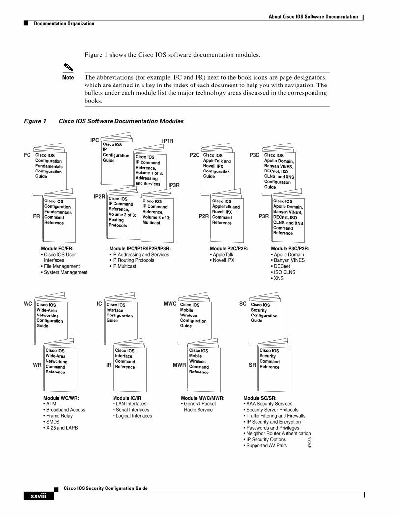
Figure 1 shows the Cisco IOS software documentation modules.
Note The abbreviations (for example, FC and FR) next to the book icons are page designators, which are defined in a key in the index of each document to help you with navigation. The bullets under each module list the major technology areas discussed in the corresponding books.
Figure 1 Cisco IOS Software Documentation Modules
Cisco IOSIP ConfigurationGuide
IPC
Cisco IOSConfigurationFundamentalsConfigurationGuide
Cisco IOSConfigurationFundamentalsCommandReference
Module FC/FR:• Cisco IOS User
Interfaces• File Management • System Management
Cisco IOSIP CommandReference,Volume 2 of 3:RoutingProtocols
Module IPC/IP1R/IP2R/IP3R:• IP Addressing and Services• IP Routing Protocols• IP Multicast
Cisco IOSAppleTalk andNovell IPXConfigurationGuide
Cisco IOSAppleTalk andNovell IPXCommandReference
Module P2C/P2R:• AppleTalk• Novell IPX
Cisco IOSApollo Domain,Banyan VINES,DECnet, ISOCLNS, and XNSConfigurationGuide
Cisco IOSApollo Domain,Banyan VINES,DECnet, ISOCLNS, and XNSCommandReference
Module P3C/P3R:• Apollo Domain• Banyan VINES• DECnet• ISO CLNS• XNS
Cisco IOSWide-AreaNetworkingConfigurationGuide
Cisco IOSWide-AreaNetworkingCommandReference
Module WC/WR:• ATM• Broadband Access• Frame Relay• SMDS• X.25 and LAPB
Cisco IOSSecurityConfigurationGuide
Cisco IOSSecurityCommandReference
Module SC/SR:• AAA Security Services• Security Server Protocols• Traffic Filtering and Firewalls• IP Security and Encryption• Passwords and Privileges• Neighbor Router Authentication• IP Security Options• Supported AV Pairs
Cisco IOSInterfaceConfigurationGuide
Cisco IOSInterfaceCommandReference
Module IC/IR:• LAN Interfaces• Serial Interfaces• Logical Interfaces
47953
FC
FR
IP2R
WC
WR
SC
SR
MWC
MWR
Cisco IOSMobileWirelessConfigurationGuide
Cisco IOSMobileWirelessCommandReference
Module MWC/MWR:• General Packet
Radio Service
IC
IR
Cisco IOSIP CommandReference,Volume 1 of 3:Addressingand Services
Cisco IOSIP CommandReference,Volume 3 of 3:Multicast
P2C
P2R
IP1R
IP3R
P3C
P3R
About Cisco IOS Software DocumentationDocumentation Organization
xxixCisco IOS Security Configuration Guide
Cisco IOSVoice, Video,and FaxConfigurationGuide
Cisco IOSVoice, Video,and FaxCommandReference
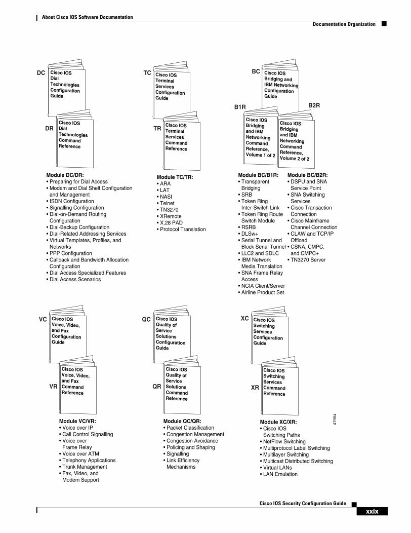
Module VC/VR:• Voice over IP• Call Control Signalling• Voice over
Frame Relay• Voice over ATM• Telephony Applications• Trunk Management• Fax, Video, and
Modem Support
Cisco IOSQuality ofServiceSolutionsConfigurationGuide
Cisco IOSQuality ofServiceSolutionsCommandReference
Module QC/QR:• Packet Classification• Congestion Management• Congestion Avoidance• Policing and Shaping• Signalling• Link Efficiency
Mechanisms
Module DC/DR:• Preparing for Dial Access• Modem and Dial Shelf Configuration
and Management• ISDN Configuration• Signalling Configuration• Dial-on-Demand Routing
Configuration• Dial-Backup Configuration• Dial-Related Addressing Services• Virtual Templates, Profiles, and
Networks• PPP Configuration• Callback and Bandwidth Allocation
Configuration• Dial Access Specialized Features• Dial Access Scenarios
Module BC/B1R:• Transparent
Bridging• SRB• Token Ring
Inter-Switch Link• Token Ring Route
Switch Module• RSRB• DLSw+• Serial Tunnel and
Block Serial Tunnel• LLC2 and SDLC• IBM Network
Media Translation• SNA Frame Relay
Access• NCIA Client/Server• Airline Product Set
Module BC/B2R:• DSPU and SNA
Service Point• SNA Switching
Services• Cisco Transaction
Connection• Cisco Mainframe
Channel Connection• CLAW and TCP/IP
Offload• CSNA, CMPC,
and CMPC+• TN3270 Server
Cisco IOSSwitchingServicesConfigurationGuide
Cisco IOSSwitchingServicesCommandReference
Module XC/XR:• Cisco IOS
Switching Paths• NetFlow Switching• Multiprotocol Label Switching• Multilayer Switching• Multicast Distributed Switching• Virtual LANs• LAN Emulation
47954
Cisco IOSBridging andIBM NetworkingConfigurationGuide
Cisco IOSBridgingand IBMNetworkingCommandReference,Volume 1 of 2
Cisco IOSBridgingand IBMNetworkingCommandReference,Volume 2 of 2
XC
DC
DR
TC
TR
BC
XR
B1R B2R
QC
QR
VC
VR
Cisco IOSTerminalServicesConfigurationGuide
Cisco IOSTerminalServicesCommandReference
Module TC/TR:• ARA• LAT• NASI• Telnet• TN3270• XRemote• X.28 PAD• Protocol Translation
Cisco IOSDialTechnologiesConfigurationGuide
Cisco IOSDialTechnologiesCommandReference
About Cisco IOS Software DocumentationDocumentation Organization
xxxCisco IOS Security Configuration Guide
Master IndexesTwo master indexes provide indexing information for the Cisco IOS software documentation set: an index for the configuration guides and an index for the command references. Individual books also contain a book-specific index.
The master indexes provide a quick way for you to find a command when you know the command name but not which module contains the command. When you use the online master indexes, you can click the page number for an index entry and go to that page in the online document.
Supporting Documents and ResourcesThe following documents and resources support the Cisco IOS software documentation set:
• Cisco IOS Command Summary (three volumes)—This publication explains the function and syntax of the Cisco IOS software commands. For more information about defaults and usage guidelines, refer to the Cisco IOS command reference publications.
• Cisco IOS System Error Messages—This publication lists and describes Cisco IOS system error messages. Not all system error messages indicate problems with your system. Some are purely informational, and others may help diagnose problems with communications lines, internal hardware, or the system software.
• Cisco IOS Debug Command Reference—This publication contains an alphabetical listing of the debug commands and their descriptions. Documentation for each command includes a brief description of its use, command syntax, usage guidelines, and sample output.
• Dictionary of Internetworking Terms and Acronyms—This Cisco publication compiles and defines the terms and acronyms used in the internetworking industry.
• New feature documentation—The Cisco IOS software documentation set documents the mainline release of Cisco IOS software (for example, Cisco IOS Release 12.2). New software features are introduced in early deployment releases (for example, the Cisco IOS “T” release train for 12.2, 12.2(x)T). Documentation for these new features can be found in standalone documents called “feature modules.” Feature module documentation describes new Cisco IOS software and hardware networking functionality and is available on Cisco.com and the Documentation CD-ROM.
• Release notes—This documentation describes system requirements, provides information about new and changed features, and includes other useful information about specific software releases. See the section “Using Software Release Notes” in the chapter “Using Cisco IOS Software” for more information.
• Caveats documentation—This documentation provides information about Cisco IOS software defects in specific software releases.
• RFCs—RFCs are standards documents maintained by the Internet Engineering Task Force (IETF). Cisco IOS software documentation references supported RFCs when applicable. The full text of referenced RFCs may be obtained on the World Wide Web at http://www.rfc-editor.org/.
• MIBs—MIBs are used for network monitoring. For lists of supported MIBs by platform and release, and to download MIB files, see the Cisco MIB website on Cisco.com at http://www.cisco.com/public/sw-center/netmgmt/cmtk/mibs.shtml.
About Cisco IOS Software DocumentationNew and Changed Information
xxxiCisco IOS Security Configuration Guide
New and Changed InformationThe following is new or changed information since the last release of the Cisco IOS Security Configuration Guide:
• A new chapter titled “Configuring Secure Shell” has been added to the section “Other Security Features.” This chapter describes SSH, which consists of a protocol and application that provide a secure replacement to the Berkeley r-tools.
• The “RADIUS Attributes” appendix has been expanded to include attribute information such as a RADIUS packet format description and RADIUS files. For more information, refer to the RADIUS Attributes appendix at the end of the book.
• The chapter titled “Configuring Cisco Encryption Technology” has been deleted from the section “IP Security and Encryption.” This functionality is no longer supported. For information regarding CET configuration, refer to Cisco IOS Security Configuration Guide release 12.1 or earlier.
Document ConventionsWithin Cisco IOS software documentation, the term router is generally used to refer to a variety of Cisco products (for example, routers, access servers, and switches). Routers, access servers, and other networking devices that support Cisco IOS software are shown interchangeably within examples. These products are used only for illustrative purposes; that is, an example that shows one product does not necessarily indicate that other products are not supported.
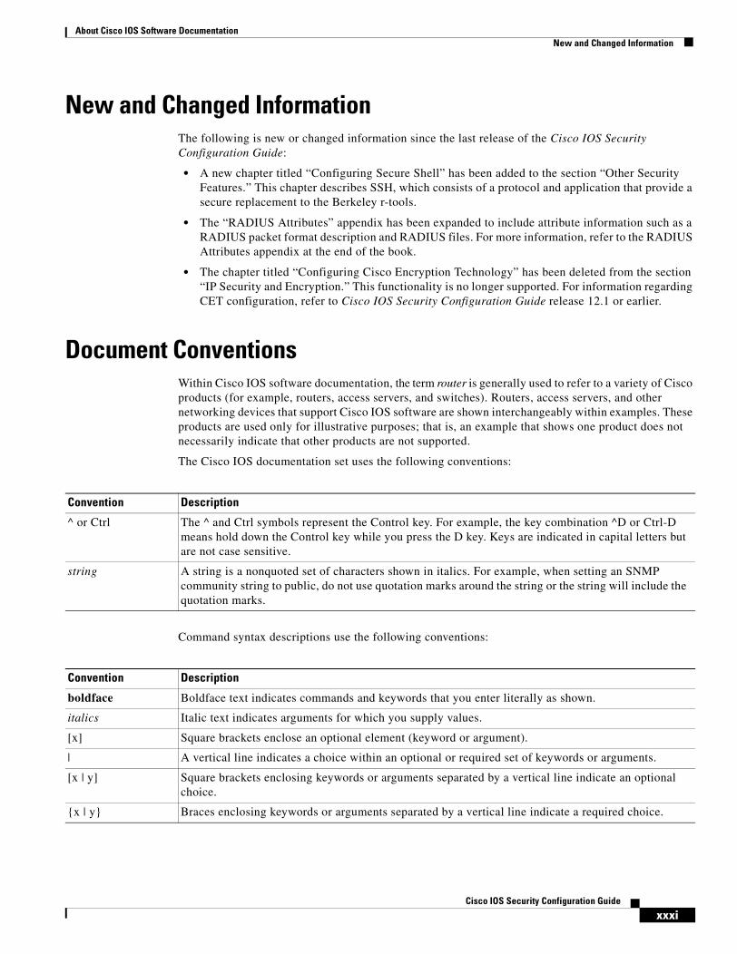
The Cisco IOS documentation set uses the following conventions:
Command syntax descriptions use the following conventions:
Convention Description
^ or Ctrl The ^ and Ctrl symbols represent the Control key. For example, the key combination ^D or Ctrl-D means hold down the Control key while you press the D key. Keys are indicated in capital letters but are not case sensitive.
string A string is a nonquoted set of characters shown in italics. For example, when setting an SNMP community string to public, do not use quotation marks around the string or the string will include the quotation marks.
Convention Description
boldface Boldface text indicates commands and keywords that you enter literally as shown.
italics Italic text indicates arguments for which you supply values.
[x] Square brackets enclose an optional element (keyword or argument).
| A vertical line indicates a choice within an optional or required set of keywords or arguments.
[x | y] Square brackets enclosing keywords or arguments separated by a vertical line indicate an optional choice.
{x | y} Braces enclosing keywords or arguments separated by a vertical line indicate a required choice.
About Cisco IOS Software DocumentationObtaining Documentation
xxxiiCisco IOS Security Configuration Guide
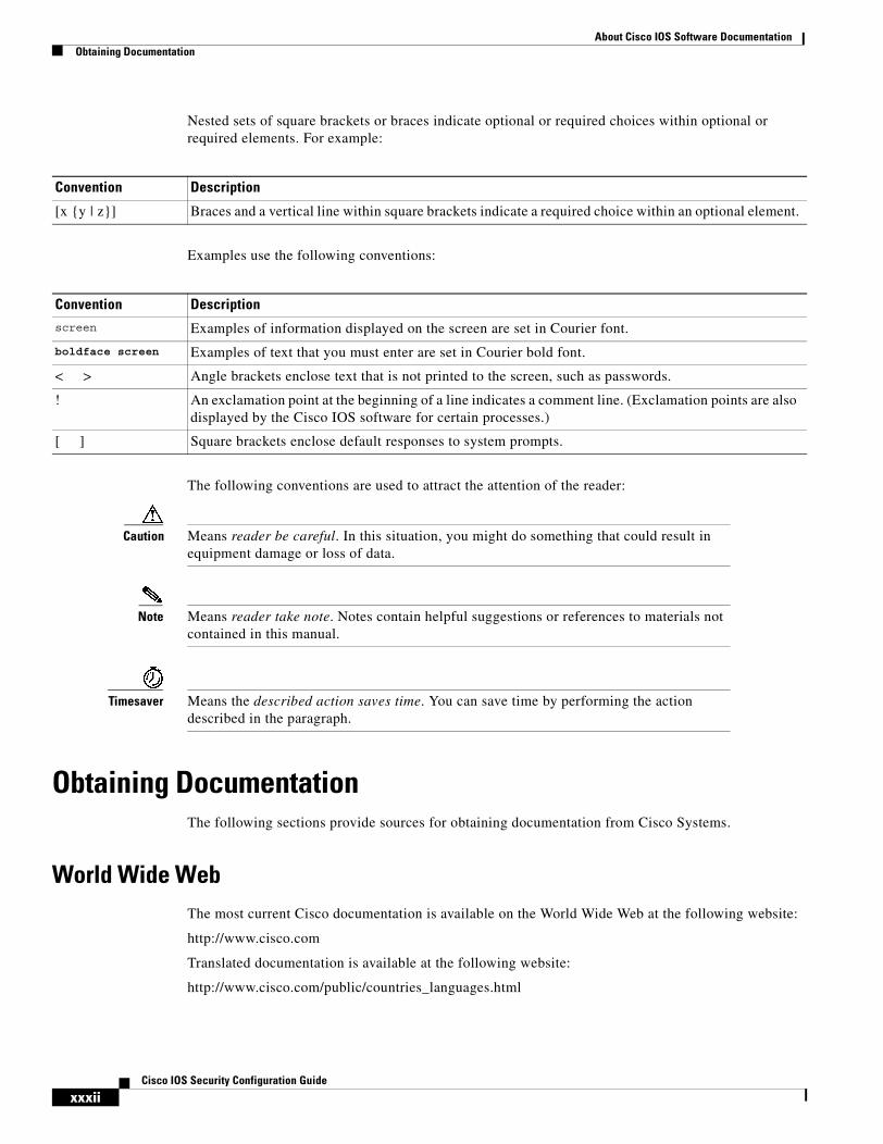
Nested sets of square brackets or braces indicate optional or required choices within optional or required elements. For example:
Examples use the following conventions:
The following conventions are used to attract the attention of the reader:
Caution Means reader be careful. In this situation, you might do something that could result in equipment damage or loss of data.
Note Means reader take note. Notes contain helpful suggestions or references to materials not contained in this manual.
Timesaver Means the described action saves time. You can save time by performing the action described in the paragraph.
Obtaining DocumentationThe following sections provide sources for obtaining documentation from Cisco Systems.
World Wide WebThe most current Cisco documentation is available on the World Wide Web at the following website:
http://www.cisco.com
Translated documentation is available at the following website:
http://www.cisco.com/public/countries_languages.html
Convention Description
[x {y | z}] Braces and a vertical line within square brackets indicate a required choice within an optional element.
Convention Descriptionscreen Examples of information displayed on the screen are set in Courier font.
boldface screen Examples of text that you must enter are set in Courier bold font.
< > Angle brackets enclose text that is not printed to the screen, such as passwords.
! An exclamation point at the beginning of a line indicates a comment line. (Exclamation points are also displayed by the Cisco IOS software for certain processes.)
[ ] Square brackets enclose default responses to system prompts.
About Cisco IOS Software DocumentationDocumentation Feedback
xxxiiiCisco IOS Security Configuration Guide
Documentation CD-ROMCisco documentation and additional literature are available in a CD-ROM package, which ships with your product. The Documentation CD-ROM is updated monthly and may be more current than printed documentation. The CD-ROM package is available as a single unit or through an annual subscription.
Ordering DocumentationCisco documentation can be ordered in the following ways:
• Registered Cisco Direct Customers can order Cisco product documentation from the Networking Products MarketPlace:
http://www.cisco.com/cgi-bin/order/order_root.pl
• Registered Cisco.com users can order the Documentation CD-ROM through the online Subscription Store:
http://www.cisco.com/go/subscription
• Nonregistered Cisco.com users can order documentation through a local account representative by calling Cisco corporate headquarters (California, USA) at 408 526-7208 or, in North America, by calling 800 553-NETS(6387).
Documentation FeedbackIf you are reading Cisco product documentation on the World Wide Web, you can submit technical comments electronically. Click Feedback in the toolbar and select Documentation. After you complete the form, click Submit to send it to Cisco.
You can e-mail your comments to [email protected].
To submit your comments by mail, use the response card behind the front cover of your document, or write to the following address:
Cisco Systems, Inc.Document Resource Connection170 West Tasman DriveSan Jose, CA 95134-9883
We appreciate your comments.
Obtaining Technical AssistanceCisco provides Cisco.com as a starting point for all technical assistance. Customers and partners can obtain documentation, troubleshooting tips, and sample configurations from online tools. For Cisco.com registered users, additional troubleshooting tools are available from the TAC website.
About Cisco IOS Software DocumentationObtaining Technical Assistance
xxxivCisco IOS Security Configuration Guide
Cisco.comCisco.com is the foundation of a suite of interactive, networked services that provides immediate, open access to Cisco information and resources at anytime, from anywhere in the world. This highly integrated Internet application is a powerful, easy-to-use tool for doing business with Cisco.
Cisco.com provides a broad range of features and services to help customers and partners streamline business processes and improve productivity. Through Cisco.com, you can find information about Cisco and our networking solutions, services, and programs. In addition, you can resolve technical issues with online technical support, download and test software packages, and order Cisco learning materials and merchandise. Valuable online skill assessment, training, and certification programs are also available.
Customers and partners can self-register on Cisco.com to obtain additional personalized information and services. Registered users can order products, check on the status of an order, access technical support, and view benefits specific to their relationships with Cisco.
To access Cisco.com, go to the following website:
http://www.cisco.com
Technical Assistance CenterThe Cisco TAC website is available to all customers who need technical assistance with a Cisco product or technology that is under warranty or covered by a maintenance contract.
Contacting TAC by Using the Cisco TAC Website
If you have a priority level 3 (P3) or priority level 4 (P4) problem, contact TAC by going to the TAC website:
http://www.cisco.com/tac
P3 and P4 level problems are defined as follows:
• P3—Your network performance is degraded. Network functionality is noticeably impaired, but most business operations continue.
• P4—You need information or assistance on Cisco product capabilities, product installation, or basic product configuration.
In each of the above cases, use the Cisco TAC website to quickly find answers to your questions.
To register for Cisco.com, go to the following website:
http://www.cisco.com/register/
If you cannot resolve your technical issue by using the TAC online resources, Cisco.com registered users can open a case online by using the TAC Case Open tool at the following website:
http://www.cisco.com/tac/caseopen
About Cisco IOS Software DocumentationObtaining Technical Assistance
xxxvCisco IOS Security Configuration Guide
Contacting TAC by Telephone
If you have a priority level 1 (P1) or priority level 2 (P2) problem, contact TAC by telephone and immediately open a case. To obtain a directory of toll-free numbers for your country, go to the following website:
http://www.cisco.com/warp/public/687/Directory/DirTAC.shtml
P1 and P2 level problems are defined as follows:
• P1—Your production network is down, causing a critical impact to business operations if service is not restored quickly. No workaround is available.
• P2—Your production network is severely degraded, affecting significant aspects of your business operations. No workaround is available.

About Cisco IOS Software DocumentationObtaining Technical Assistance
xxxviCisco IOS Security Configuration Guide
xxxviiCisco IOS Security Configuration Guide
Using Cisco IOS Software
This chapter provides helpful tips for understanding and configuring Cisco IOS software using the command-line interface (CLI). It contains the following sections:
• Understanding Command Modes
• Getting Help
• Using the no and default Forms of Commands
• Saving Configuration Changes
• Filtering Output from the show and more Commands
• Identifying Supported Platforms
For an overview of Cisco IOS software configuration, refer to the Cisco IOS Configuration Fundamentals Configuration Guide.
For information on the conventions used in the Cisco IOS software documentation set, see the chapter “About Cisco IOS Software Documentation” located at the beginning of this book.
Understanding Command ModesYou use the CLI to access Cisco IOS software. Because the CLI is divided into many different modes, the commands available to you at any given time depend on the mode you are currently in. Entering a question mark (?) at the CLI prompt allows you to obtain a list of commands available for each command mode.
When you log in to the CLI, you are in user EXEC mode. User EXEC mode contains only a limited subset of commands. To have access to all commands, you must enter privileged EXEC mode, normally by using a password. From privileged EXEC mode you can issue any EXEC command—user or privileged mode—or you can enter global configuration mode. Most EXEC commands are one-time commands. For example, show commands show important status information, and clear commands clear counters or interfaces. The EXEC commands are not saved when the software reboots.
Configuration modes allow you to make changes to the running configuration. If you later save the running configuration to the startup configuration, these changed commands are stored when the software is rebooted. To enter specific configuration modes, you must start at global configuration mode. From global configuration mode, you can enter interface configuration mode and a variety of other modes, such as protocol-specific modes.
ROM monitor mode is a separate mode used when the Cisco IOS software cannot load properly. If a valid software image is not found when the software boots or if the configuration file is corrupted at startup, the software might enter ROM monitor mode.
Using Cisco IOS SoftwareGetting Help
xxxviiiCisco IOS Security Configuration Guide
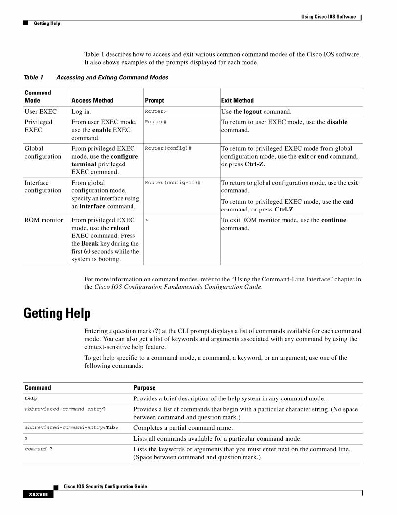
Table 1 describes how to access and exit various common command modes of the Cisco IOS software. It also shows examples of the prompts displayed for each mode.
For more information on command modes, refer to the “Using the Command-Line Interface” chapter in the Cisco IOS Configuration Fundamentals Configuration Guide.
Getting HelpEntering a question mark (?) at the CLI prompt displays a list of commands available for each command mode. You can also get a list of keywords and arguments associated with any command by using the context-sensitive help feature.
To get help specific to a command mode, a command, a keyword, or an argument, use one of the following commands:
Table 1 Accessing and Exiting Command Modes
Command Mode Access Method Prompt Exit Method
User EXEC Log in. Router> Use the logout command.
Privileged EXEC
From user EXEC mode, use the enable EXEC command.
Router# To return to user EXEC mode, use the disable command.
Global configuration
From privileged EXEC mode, use the configure terminal privileged EXEC command.
Router(config)# To return to privileged EXEC mode from global configuration mode, use the exit or end command, or press Ctrl-Z.
Interface configuration
From global configuration mode, specify an interface using an interface command.
Router(config-if)# To return to global configuration mode, use the exit command.
To return to privileged EXEC mode, use the end command, or press Ctrl-Z.
ROM monitor From privileged EXEC mode, use the reload EXEC command. Press the Break key during the first 60 seconds while the system is booting.
> To exit ROM monitor mode, use the continue command.
Command Purpose
help Provides a brief description of the help system in any command mode.
abbreviated-command-entry? Provides a list of commands that begin with a particular character string. (No space between command and question mark.)
abbreviated-command-entry<Tab> Completes a partial command name.
? Lists all commands available for a particular command mode.
command ? Lists the keywords or arguments that you must enter next on the command line. (Space between command and question mark.)
Using Cisco IOS SoftwareGetting Help
xxxixCisco IOS Security Configuration Guide
Example: How to Find Command OptionsThis section provides an example of how to display syntax for a command. The syntax can consist of optional or required keywords and arguments. To display keywords and arguments for a command, enter a question mark (?) at the configuration prompt or after entering part of a command followed by a space. The Cisco IOS software displays a list and brief description of available keywords and arguments. For example, if you were in global configuration mode and wanted to see all the keywords or arguments for the arap command, you would type arap ?.
The <cr> symbol in command help output stands for “carriage return.” On older keyboards, the carriage return key is the Return key. On most modern keyboards, the carriage return key is the Enter key. The <cr> symbol at the end of command help output indicates that you have the option to press Enter to complete the command and that the arguments and keywords in the list preceding the <cr> symbol are optional. The <cr> symbol by itself indicates that no more arguments or keywords are available and that you must press Enter to complete the command.
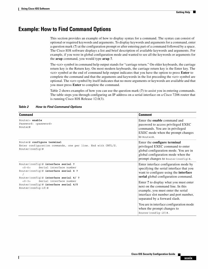
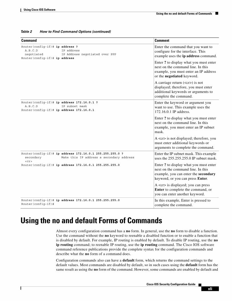
Table 2 shows examples of how you can use the question mark (?) to assist you in entering commands. The table steps you through configuring an IP address on a serial interface on a Cisco 7206 router that is running Cisco IOS Release 12.0(3).
Table 2 How to Find Command Options
Command Comment
Router> enablePassword: <password>Router#
Enter the enable command and password to access privileged EXEC commands. You are in privileged EXEC mode when the prompt changes to Router#.
Router# configure terminalEnter configuration commands, one per line. End with CNTL/Z.Router(config)#
Enter the configure terminal privileged EXEC command to enter global configuration mode. You are in global configuration mode when the prompt changes to Router(config)#.
Router(config)# interface serial ?<0-6> Serial interface number
Router(config)# interface serial 4 ?/
Router(config)# interface serial 4/ ?<0-3> Serial interface number
Router(config)# interface serial 4/0Router(config-if)#
Enter interface configuration mode by specifying the serial interface that you want to configure using the interface serial global configuration command.
Enter ? to display what you must enter next on the command line. In this example, you must enter the serial interface slot number and port number, separated by a forward slash.
You are in interface configuration mode when the prompt changes to Router(config-if)#.
Using Cisco IOS SoftwareGetting Help
xlCisco IOS Security Configuration Guide
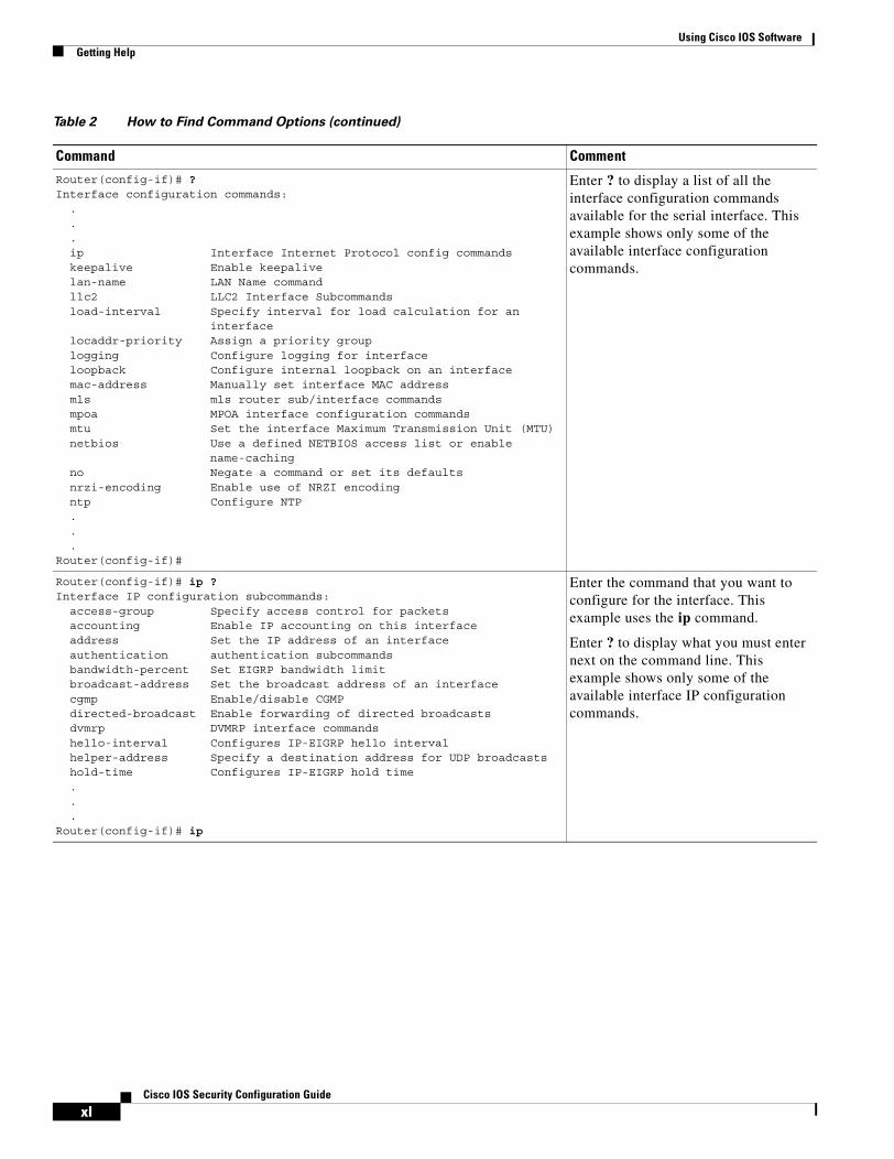
Router(config-if)# ?Interface configuration commands:
.
.
.ip Interface Internet Protocol config commandskeepalive Enable keepalivelan-name LAN Name commandllc2 LLC2 Interface Subcommandsload-interval Specify interval for load calculation for an
interfacelocaddr-priority Assign a priority grouplogging Configure logging for interfaceloopback Configure internal loopback on an interfacemac-address Manually set interface MAC addressmls mls router sub/interface commandsmpoa MPOA interface configuration commandsmtu Set the interface Maximum Transmission Unit (MTU)netbios Use a defined NETBIOS access list or enable
name-cachingno Negate a command or set its defaultsnrzi-encoding Enable use of NRZI encodingntp Configure NTP...
Router(config-if)#
Enter ? to display a list of all the interface configuration commands available for the serial interface. This example shows only some of the available interface configuration commands.
Router(config-if)# ip ?Interface IP configuration subcommands:
access-group Specify access control for packetsaccounting Enable IP accounting on this interfaceaddress Set the IP address of an interfaceauthentication authentication subcommandsbandwidth-percent Set EIGRP bandwidth limitbroadcast-address Set the broadcast address of an interfacecgmp Enable/disable CGMPdirected-broadcast Enable forwarding of directed broadcastsdvmrp DVMRP interface commandshello-interval Configures IP-EIGRP hello intervalhelper-address Specify a destination address for UDP broadcastshold-time Configures IP-EIGRP hold time...
Router(config-if)# ip
Enter the command that you want to configure for the interface. This example uses the ip command.
Enter ? to display what you must enter next on the command line. This example shows only some of the available interface IP configuration commands.
Table 2 How to Find Command Options (continued)
Command Comment
Using Cisco IOS SoftwareUsing the no and default Forms of Commands
xliCisco IOS Security Configuration Guide
Using the no and default Forms of CommandsAlmost every configuration command has a no form. In general, use the no form to disable a function. Use the command without the no keyword to reenable a disabled function or to enable a function that is disabled by default. For example, IP routing is enabled by default. To disable IP routing, use the no ip routing command; to reenable IP routing, use the ip routing command. The Cisco IOS software command reference publications provide the complete syntax for the configuration commands and describe what the no form of a command does.
Configuration commands also can have a default form, which returns the command settings to the default values. Most commands are disabled by default, so in such cases using the default form has the same result as using the no form of the command. However, some commands are enabled by default and
Router(config-if)# ip address ?A.B.C.D IP addressnegotiated IP Address negotiated over PPP
Router(config-if)# ip address
Enter the command that you want to configure for the interface. This example uses the ip address command.
Enter ? to display what you must enter next on the command line. In this example, you must enter an IP address or the negotiated keyword.
A carriage return (<cr>) is not displayed; therefore, you must enter additional keywords or arguments to complete the command.
Router(config-if)# ip address 172.16.0.1 ?A.B.C.D IP subnet mask
Router(config-if)# ip address 172.16.0.1
Enter the keyword or argument you want to use. This example uses the 172.16.0.1 IP address.
Enter ? to display what you must enter next on the command line. In this example, you must enter an IP subnet mask.
A <cr> is not displayed; therefore, you must enter additional keywords or arguments to complete the command.
Router(config-if)# ip address 172.16.0.1 255.255.255.0 ?secondary Make this IP address a secondary address<cr>
Router(config-if)# ip address 172.16.0.1 255.255.255.0
Enter the IP subnet mask. This example uses the 255.255.255.0 IP subnet mask.
Enter ? to display what you must enter next on the command line. In this example, you can enter the secondary keyword, or you can press Enter.
A <cr> is displayed; you can press Enter to complete the command, or you can enter another keyword.
Router(config-if)# ip address 172.16.0.1 255.255.255.0Router(config-if)#
In this example, Enter is pressed to complete the command.
Table 2 How to Find Command Options (continued)
Command Comment

Using Cisco IOS SoftwareSaving Configuration Changes
xliiCisco IOS Security Configuration Guide
have variables set to certain default values. In these cases, the default form of the command enables the command and sets the variables to their default values. The Cisco IOS software command reference publications describe the effect of the default form of a command if the command functions differently than the no form.
Saving Configuration ChangesUse the copy system:running-config nvram:startup-config command to save your configuration changes to the startup configuration so that the changes will not be lost if the software reloads or a power outage occurs. For example:
Router# copy system:running-config nvram:startup-configBuilding configuration...
It might take a minute or two to save the configuration. After the configuration has been saved, the following output appears:
[OK]Router#
On most platforms, this task saves the configuration to NVRAM. On the Class A Flash file system platforms, this task saves the configuration to the location specified by the CONFIG_FILE environment variable. The CONFIG_FILE variable defaults to NVRAM.
Filtering Output from the show and more CommandsIn Cisco IOS Release 12.0(1)T and later releases, you can search and filter the output of show and more commands. This functionality is useful if you need to sort through large amounts of output or if you want to exclude output that you need not see.
To use this functionality, enter a show or more command followed by the “pipe” character (|); one of the keywords begin, include, or exclude; and a regular expression on which you want to search or filter (the expression is case-sensitive):
command | {begin | include | exclude} regular-expression
The output matches certain lines of information in the configuration file. The following example illustrates how to use output modifiers with the show interface command when you want the output to include only lines in which the expression “protocol” appears:
Router# show interface | include protocol
FastEthernet0/0 is up, line protocol is upSerial4/0 is up, line protocol is upSerial4/1 is up, line protocol is upSerial4/2 is administratively down, line protocol is downSerial4/3 is administratively down, line protocol is down
For more information on the search and filter functionality, refer to the “Using the Command-Line Interface” chapter in the Cisco IOS Configuration Fundamentals Configuration Guide.
Using Cisco IOS SoftwareIdentifying Supported Platforms
xliiiCisco IOS Security Configuration Guide
Identifying Supported PlatformsCisco IOS software is packaged in feature sets consisting of software images that support specific platforms. The feature sets available for a specific platform depend on which Cisco IOS software images are included in a release. To identify the set of software images available in a specific release or to find out if a feature is available in a given Cisco IOS software image, see the following sections:
• Using Feature Navigator
• Using Software Release Notes
Using Feature NavigatorFeature Navigator is a web-based tool that enables you to quickly determine which Cisco IOS software images support a particular set of features and which features are supported in a particular Cisco IOS image.
Feature Navigator is available 24 hours a day, 7 days a week. To access Feature Navigator, you must have an account on Cisco.com. If you have forgotten or lost your account information, e-mail the Contact Database Administration group at [email protected]. If you do not have an account on Cisco.com, go to http://www.cisco.com/register and follow the directions to establish an account.
To use Feature Navigator, you must have a JavaScript-enabled web browser such as Netscape 3.0 or later, or Internet Explorer 4.0 or later. Internet Explorer 4.0 always has JavaScript enabled. To enable JavaScript for Netscape 3.x or Netscape 4.x, follow the instructions provided with the web browser. For JavaScript support and enabling instructions for other browsers, check with the browser vendor.
Feature Navigator is updated when major Cisco IOS software releases and technology releases occur. You can access Feature Navigator at the following URL:
http://www.cisco.com/go/fn
Using Software Release NotesCisco IOS software releases include release notes that provide the following information:
• Platform support information
• Memory recommendations
• Microcode support information
• Feature set tables
• Feature descriptions
• Open and resolved severity 1 and 2 caveats for all platforms
Release notes are intended to be release-specific for the most current release, and the information provided in these documents may not be cumulative in providing information about features that first appeared in previous releases.

Using Cisco IOS SoftwareIdentifying Supported Platforms
xlivCisco IOS Security Configuration Guide
SC-1Cisco IOS Security Configuration Guide
Security Overview
This chapter contains the following sections:
• About This Guide
Preview the topics in this guide.
• Creating Effective Security Policies
Learn tips and hints for creating a security policy for your organization. A security policy should be finalized and up to date before you configure any security features.
• Identifying Security Risks and Cisco IOS Solutions
Identify common security risks that might be present in your network, and find the right Cisco IOS security feature to prevent security break-ins.
About This GuideThe Cisco IOS Security Configuration Guide describes how to configure Cisco IOS security features for your Cisco networking devices. These security features can protect your network against degradation or failure and also against data loss or compromise resulting from intentional attacks and from unintended but damaging mistakes by well-meaning network users.
This guide is divided into five parts:
• Authentication, Authorization, and Accounting (AAA)
• Security Server Protocols
• Traffic Filtering and Firewalls
• IP Security and Encryption
• Other Security Features
Appendixes follow the five main divisions.
The following sections briefly describe each of these parts and the appendixes.
Security OverviewAbout This Guide
SC-2Cisco IOS Security Configuration Guide
Authentication, Authorization, and Accounting (AAA)This part describes how to configure Cisco’s authentication, authorization, and accounting (AAA) paradigm. AAA is an architectural framework for configuring a set of three independent security functions in a consistent, modular manner.
• Authentication—Provides the method of identifying users, including login and password dialog, challenge and response, messaging support, and, depending on the security protocol you select, encryption. Authentication is the way a user is identified prior to being allowed access to the network and network services. You configure AAA authentication by defining a named list of authentication methods and then applying that list to various interfaces.
• Authorization—Provides the method for remote access control, including one-time authorization or authorization for each service, per-user account list and profile, user group support, and support of IP, IPX, ARA, and Telnet.
Remote security servers, such as RADIUS and TACACS+, authorize users for specific rights by associating attribute-value (AV) pairs, which define those rights, with the appropriate user. AAA authorization works by assembling a set of attributes that describe what the user is authorized to perform. These attributes are compared with the information contained in a database for a given user, and the result is returned to AAA to determine the user’s actual capabilities and restrictions.
• Accounting—Provides the method for collecting and sending security server information used for billing, auditing, and reporting, such as user identities, start and stop times, executed commands (such as PPP), number of packets, and number of bytes. Accounting enables you to track the services users are accessing, as well as the amount of network resources they are consuming.
Note You can configure authentication outside of AAA. However, you must configure AAA if you want to use RADIUS, TACACS+, or Kerberos or if you want to configure a backup authentication method.
Security Server ProtocolsIn many circumstances, AAA uses security protocols to administer its security functions. If your router or access server is acting as a network access server, AAA is the means through which you establish communication between your network access server and your RADIUS, TACACS+, or Kerberos security server.
The chapters in this part describe how to configure the following security server protocols:
• RADIUS—A distributed client/server system implemented through AAA that secures networks against unauthorized access. In the Cisco implementation, RADIUS clients run on Cisco routers and send authentication requests to a central RADIUS server that contains all user authentication and network service access information.
• TACACS+—A security application implemented through AAA that provides centralized validation of users attempting to gain access to a router or network access server. TACACS+ services are maintained in a database on a TACACS+ daemon running, typically, on a UNIX or Windows NT workstation. TACACS+ provides for separate and modular authentication, authorization, and accounting facilities.
• Kerberos—A secret-key network authentication protocol implemented through AAA that uses the Data Encryption Standard (DES) cryptographic algorithm for encryption and authentication. Kerberos was designed to authenticate requests for network resources. Kerberos is based on the concept of a trusted third party that performs secure verification of users and services. The primary use of Kerberos is to verify that users and the network services they use are really who and what
Security OverviewAbout This Guide
SC-3Cisco IOS Security Configuration Guide
they claim to be. To accomplish this, a trusted Kerberos server issues tickets to users. These tickets, which have a limited lifespan, are stored in a user’s credential cache and can be used in place of the standard username-and-password authentication mechanism.
Traffic Filtering and FirewallsThis part describes how to configure your networking devices to filter traffic or to function as a firewall.
• Cisco implements traffic filters with access control lists (also called access lists). Access lists determine what traffic is blocked and what traffic is forwarded at router interfaces. Cisco provides both basic and advanced access list capabilities.
– Basic access lists
An overview of basic access lists is in the chapter “Access Control Lists: Overview and Guidelines.” This chapter describes tips, cautions, considerations, recommendations, and general guidelines for configuring access lists for the various network protocols. You should configure basic access lists for all network protocols that will be routed through your networking device, such as IP, IPX, AppleTalk, and so forth.
– Advanced access lists
The advanced access list capabilities and configuration are described in the remaining chapters in the “Traffic Filtering and Firewalls” part of this document. The advanced access lists provide sophisticated and dynamic traffic filtering capabilities for stronger, more flexible network security.
• Cisco IOS Firewall provides an extensive set of security features, allowing you to configure a simple or elaborate firewall, according to your particular requirements. The following features are key components of Cisco IOS Firewall:
– Context-based Access Control (CBAC)
CBAC intelligently filters TCP and UDP packets based on application-layer protocol session information. You can configure CBAC to permit specified TCP and UDP traffic through a firewall only when the connection is initiated from within the network you want to protect. CBAC can inspect traffic for sessions that originate from either side of the firewall, and CBAC can be used for intranet, extranet, and Internet perimeters of your network.
– Cisco IOS Firewall Intrusion Detection System (IDS)
The Cisco IOS Firewall IDS supports intrusion detection technology for mid-range and high-end router platforms with firewall support. It identifies 59 of the most common attacks using “signatures” to detect patterns of misuse in network traffic. The Cisco IOS Firewall IDS acts as an in-line intrusion detection sensor, watching packets and sessions as they flow through the router, scanning each to match any of the IDS signatures. When it detects suspicious activity, it responds before network security can be compromised and logs the event through Cisco IOS syslog.
Cisco IOS Firewall IDS is compatible with the Cisco Secure Intrusion Detection System (formally known as NetRanger)—an enterprise-scale, real-time intrusion detection system designed to detect, report, and terminate unauthorized activity throughout a network.
– Authentication Proxy
The Cisco IOS Firewall authentication proxy feature allows network administrators to apply specific security policies on a per-user basis. Previously, user identity and related authorized access were associated with a user’s IP address, or a single security policy had to be applied to
Security OverviewAbout This Guide
SC-4Cisco IOS Security Configuration Guide
an entire user group or sub network. Now, users can be identified and authorized on the basis of their per-user policy, and access privileges tailored on an individual basis are possible, as opposed to general policy applied across multiple users.
– Port to Application Mapping (PAM)
Port to Application Mapping (PAM) is a feature of Cisco Secure Integrated Software. PAM allows you to customize TCP or UDP port numbers for network services or applications. PAM uses this information to support network environments that run services using ports that are different from the registered or well-known ports associated with an application. For example, the information in the PAM table enables Context-based Access Control (CBAC) supported services to run on non-standard ports.
Firewalls are discussed in the chapters “Cisco IOS Firewall Overview” and “Configuring Context-Based Access Control.”
IP Security and EncryptionThis part describes how to configure IP security and encryption in the following chapters:
• Configuring IPSec Network Security
This chapter describes how to configure IPSec. IPSec provides security for transmission of sensitive information over unprotected networks such as the Internet IPSec provides data authentication and anti-replay services in addition to data confidentiality services.
• Configuring Certification Authority Interoperability
This chapter describes how to configure certification authority (CA) interoperability. CA interoperability permits Cisco IOS devices and CAs to communicate so that your Cisco IOS device can obtain and use digital certificates from the CA.
• Configuring Internet Key Exchange Security Protocol
This chapter describes how to configure Internet Key Exchange (IKE). IKE is a key management protocol standard that is used in conjunction with the IPSec standard. IPSec can be configured without IKE, but IKE enhances IPSec by providing additional features, flexibility, and ease of configuration for the IPSec standard.
Other Security FeaturesThis part describes four important security features in the following chapters:
• Configuring Passwords and Privileges
This chapter describes how to configure static passwords stored on your networking device. These passwords are used to control access to the device’s command line prompt to view or change the device configuration.
This chapter also describes how to assign privilege levels to the passwords. You can configure up to 16 different privilege levels and assign each level to a password. For each privilege level you define a subset of Cisco IOS commands that can be executed. You can use these different levels to allow some users the ability to execute all Cisco IOS commands, and to restrict other users to a defined subset of commands.
This chapter also describes how to recover lost passwords.
Security OverviewAbout This Guide
SC-5Cisco IOS Security Configuration Guide
• Neighbor Router Authentication: Overview and Guidelines
This chapter briefly describes the security benefits and operation of neighbor router authentication.
When neighbor authentication is configured on a router, the router authenticates its neighbor router before accepting any route updates from that neighbor. This ensures that a router always receives reliable routing update information from a trusted source.
• Configuring IP Security Options
This chapter describes how to configure IP Security Options (IPSO) as described in RFC 1108. IPSO is generally used to comply with the security policy of the U.S. government’s Department of Defense.
• Configuring Unicast Reverse Path Forwarding
This chapter describes the Unicast Reverse Path Forwarding (Unicast RPF) feature, which helps mitigate problems caused by the introduction of malformed or forged (spoofed) IP source addresses into a network by discarding IP packets that lack a verifiable IP source address. For example, a number of common types of denial-of-service (DoS) attacks, including Smurf and Tribe Flood Network (TFN), can take advantage of forged or rapidly changing source IP addresses to allow attackers to thwart efforts to locate or filter the attacks. For Internet service providers (ISPs) that provide public access, Unicast RPF deflects such attacks by forwarding only packets that have source addresses that are valid and consistent with the IP routing table. This action protects the network of the ISP, its customer, and the rest of the Internet.
• Configuring Secure Shell
This chapter describes the Secure Shell (SSH) feature. SSH is an application and a protocol that provides a secure replacement to a suite of Unix r-commands such as rsh, rlogin and rcp. (Cisco IOS supports rlogin.) The protocol secures the sessions using standard cryptographic mechanisms, and the application can be used similarly to the Berkeley rexec and rsh tools. There are currently two versions of SSH available: SSH Version 1 and SSH Version 2. Only SSH Version 1 is implemented in the Cisco IOS software.
AppendixesThe appendixes describe the supported RADIUS attributes and TACACS+ attribute-value pairs as follows:
• RADIUS Attributes
RADIUS attributes are used to define specific AAA elements in a user profile, which is stored on the RADIUS daemon. This appendix lists the RADIUS attributes currently supported.
• TACACS+ Attribute-Value Pairs
TACACS+ attribute-value pairs are used to define specific AAA elements in a user profile, which is stored on the TACACS+ daemon. This appendix lists the TACACS+ attribute-value pairs currently supported.
Security OverviewCreating Effective Security Policies
SC-6Cisco IOS Security Configuration Guide
Creating Effective Security PoliciesAn effective security policy works to ensure that your organization’s network assets are protected from sabotage and from inappropriate access—both intentional and accidental.
All network security features should be configured in compliance with your organization’s security policy. If you do not have a security policy, or if your policy is out of date, you should ensure that the policy is created or updated before you decide how to configure security on your Cisco device.
The following sections provide guidelines to help you create an effective security policy:
• The Nature of Security Policies
• Two Levels of Security Policies
• Tips for Developing an Effective Security Policy
The Nature of Security PoliciesYou should recognize these aspects of security policies:
• Security policies represent trade-offs.
With all security policies, there is some trade-off between user productivity and security measures that can be restrictive and time consuming. The goal of any security design is to provide maximum security with minimum impact on user access and productivity. Some security measures, such as network data encryption, do not restrict access and productivity. On the other hand, cumbersome or unnecessarily redundant verification and authorization systems can frustrate users and even prevent access to critical network resources.
• Security policies should be determined by business needs.
Business needs should dictate the security policy; a security policy should not determine how a business operates.
• Security policies are living documents.
Because organizations are constantly subject to change, security policies must be systematically updated to reflect new business directions, technological changes, and resource allocations.
Two Levels of Security PoliciesYou can think of a security policy as having two levels: a requirements level and an implementation level.
• At the requirements level, a policy defines the degree to which your network assets must be protected against intrusion or destruction and also estimates the cost (consequences) of a security breach. For example, the policy could state that only human resources personnel should be able to access personnel records, or that only IS personnel should be able to configure the backbone routers. The policy could also address the consequences of a network outage (due to sabotage), and the consequences of inadvertently making sensitive information public.
• At the implementation level, a policy defines guidelines to implement the requirements-level policy, using specific technology in a predefined way. For example, the implementation-level policy could require access lists to be configured so that only traffic from human resources host computers can access the server containing personnel records.
When creating a policy, define security requirements before defining security implementations so that you do not end up merely justifying particular technical solutions that might not actually be required.
Security OverviewCreating Effective Security Policies
SC-7Cisco IOS Security Configuration Guide
Tips for Developing an Effective Security PolicyTo develop an effective security policy, consider the recommendations in the following sections:
• Identifying Your Network Assets to Protect
• Determining Points of Risk
• Limiting the Scope of Access
• Identifying Assumptions
• Determining the Cost of Security Measures
• Considering Human Factors
• Keeping a Limited Number of Secrets
• Implementing Pervasive and Scalable Security
• Understanding Typical Network Functions
• Remembering Physical Security
Identifying Your Network Assets to Protect
The first step to developing a security policy is to understand and identify your organization’s network assets. Network assets include the following:
• Networked hosts (such as PCs; includes the hosts’ operating systems, applications, and data)
• Networking devices (such as routers)
• Network data (data that travels across the network)
You must both identify your network’s assets and determine the degree to which each of these assets must be protected. For example, one subnetwork of hosts might contain extremely sensitive data that should be protected at all costs, while a different subnetwork of hosts might require only modest protection against security risks because there is less cost involved if the subnetwork is compromised.
Determining Points of Risk
You must understand how potential intruders can enter your organization’s network or sabotage network operation. Special areas of consideration are network connections, dial-up access points, and misconfigured hosts. Misconfigured hosts, frequently overlooked as points of network entry, can be systems with unprotected login accounts (guest accounts), employ extensive trust in remote commands (such as rlogin and rsh), have illegal modems attached to them, and use easy-to-break passwords.
Limiting the Scope of Access
Organizations can create multiple barriers within networks, so that unlawful entry to one part of the system does not automatically grant entry to the entire infrastructure. Although maintaining a high level of security for the entire network can be prohibitively expensive (in terms of systems and equipment as well as productivity), you can often provide higher levels of security to the more sensitive areas of your network.
Security OverviewCreating Effective Security Policies
SC-8Cisco IOS Security Configuration Guide
Identifying Assumptions
Every security system has underlying assumptions. For example, an organization might assume that its network is not tapped, that intruders are not very knowledgeable, that intruders are using standard software, or that a locked room is safe. It is important to identify, examine, and justify your assumptions: any hidden assumption is a potential security hole.
Determining the Cost of Security Measures
In general, providing security comes at a cost. This cost can be measured in terms of increased connection times or inconveniences to legitimate users accessing the assets, or in terms of increased network management requirements, and sometimes in terms of actual dollars spent on equipment or software upgrades.
Some security measures inevitably inconvenience some sophisticated users. Security can delay work, create expensive administrative and educational overhead, use significant computing resources, and require dedicated hardware.
When you decide which security measures to implement, you must understand their costs and weigh these against potential benefits. If the security costs are out of proportion to the actual dangers, it is a disservice to the organization to implement them.
Considering Human Factors
If security measures interfere with essential uses of the system, users resist these measures and sometimes even circumvent them. Many security procedures fail because their designers do not take this fact into account. For example, because automatically generated “nonsense” passwords can be difficult to remember, users often write them on the undersides of keyboards. A “secure” door that leads to a system’s only tape drive is sometimes propped open. For convenience, unauthorized modems are often connected to a network to avoid cumbersome dial-in security procedures. To ensure compliance with your security measures, users must be able to get their work done as well as understand and accept the need for security.
Any user can compromise system security to some degree. For example, an intruder might learn passwords by simply calling legitimate users on the telephone claiming to be a system administrator and asking for them. If users understand security issues and understand the reasons for them, they are far less likely to compromise security in this way.
Defining such human factors and any corresponding policies needs to be included as a formal part of your complete security policy.
At a minimum, users must be taught never to release passwords or other secrets over unsecured telephone lines (especially through cordless or cellular telephones) or electronic mail. They should be wary of questions asked by people who call them on the telephone. Some companies have implemented formalized network security training for their employees in which employees are not allowed access to the network until they have completed a formal training program.
Keeping a Limited Number of Secrets
Most security is based on secrets; for example, passwords and encryption keys are secrets. But the more secrets there are, the harder it is to keep all of them. It is prudent, therefore, to design a security policy that relies on a limited number of secrets. Ultimately, the most important secret an organization has is the information that can help someone circumvent its security.
Security OverviewIdentifying Security Risks and Cisco IOS Solutions
SC-9Cisco IOS Security Configuration Guide
Implementing Pervasive and Scalable Security
Use a systematic approach to security that includes multiple, overlapping security methods.
Almost any change that is made to a system can affect security. This is especially true when new services are created. System administrators, programmers, and users need to consider the security implications of every change they make. Understanding the security implications of a change takes practice; it requires lateral thinking and a willingness to explore every way that a service could potentially be manipulated. The goal of any security policy is to create an environment that is not susceptible to every minor change.
Understanding Typical Network Functions
Understand how your network system normally functions, know what is expected and unexpected behavior, and be familiar with how devices are usually used. This kind of awareness helps the organization detect security problems. Noticing unusual events can help catch intruders before they can damage the system. Software auditing tools can help detect, log, and track unusual events. In addition, an organization should know exactly what software it relies on to provide auditing trails, and a security system should not operate on the assumption that all software is bug free.
Remembering Physical Security
The physical security of your network devices and hosts cannot be neglected. For example, many facilities implement physical security by using security guards, closed circuit television, card-key entry systems, or other means to control physical access to network devices and hosts. Physical access to a computer or router usually gives a sophisticated user complete control over that device. Physical access to a network link usually allows a person to tap into that link, jam it, or inject traffic into it. Software security measures can often be circumvented when access to the hardware is not controlled.
Identifying Security Risks and Cisco IOS SolutionsCisco IOS software provides a comprehensive set of security features to guard against specific security risks. This section describes a few common security risks that might be present in your network, and describes how to use Cisco IOS software to protect against each of these risks:
• Preventing Unauthorized Access into Networking Devices
• Preventing Unauthorized Access into Networks
• Preventing Network Data Interception
• Preventing Fraudulent Route Updates
Preventing Unauthorized Access into Networking DevicesIf someone were to gain console or terminal access into a networking device, such as a router, switch, or network access server, that person could do significant damage to your network—perhaps by reconfiguring the device, or even by simply viewing the device’s configuration information.
Typically, you want administrators to have access to your networking device; you do not want other users on your local-area network or those dialing in to the network to have access to the router.
Security OverviewIdentifying Security Risks and Cisco IOS Solutions
SC-10Cisco IOS Security Configuration Guide
Users can access Cisco networking devices by dialing in from outside the network through an asynchronous port, connecting from outside the network through a serial port, or connecting via a terminal or workstation from within the local network.
To prevent unauthorized access into a networking device, you should configure one or more of the following security features:
• At a minimum, you should configure passwords and privileges at each networking device for all device lines and ports, as described in the chapter “Configuring Passwords and Privileges.” These passwords are stored on the networking device. When users attempt to access the device through a particular line or port, they must enter the password applied to the line or port before they can access the device.
• For an additional layer of security, you can also configure username/password pairs, stored in a database on the networking device, as described in the chapter “Configuring Passwords and Privileges.” These pairs are assigned to lines or interfaces and authenticate each user before that user can access the device. If you have defined privilege levels, you can also assign a specific privilege level (with associated rights and privileges) to each username/password pair.
• If you want to use username/password pairs, but you want to store them centrally instead of locally on each individual networking device, you can store them in a database on a security server. Multiple networking devices can then use the same database to obtain user authentication (and, if necessary, authorization) information. Cisco supports a variety of security server protocols, such as RADIUS, TACACS+, and Kerberos. If you decide to use the database on a security server to store login username/password pairs, you must configure your router or access server to support the applicable protocol; in addition, because most supported security protocols must be administered through the AAA security services, you will probably need to enable AAA. For more information about security protocols and AAA, refer to the chapters in the “Authentication, Authorization, and Accounting (AAA)” part of this document.
Note Cisco recommends that, whenever possible, AAA be used to implement authentication.
• If you want to authorize individual users for specific rights and privileges, you can implement AAA’s authorization feature, using a security protocol such as TACACS+ or RADIUS. For more information about security protocol features and AAA, refer to the chapters in the “Authentication, Authorization, and Accounting (AAA)” part of this document.
• If you want to have a backup authentication method, you must configure AAA. AAA allows you to specify the primary method for authenticating users (for example, a username/password database stored on a TACACS+ server) and then specify backup methods (for example, a locally stored username/password database.) The backup method is used if the primary method’s database cannot be accessed by the networking device. To configure AAA, refer to the chapters in the “Authentication, Authorization, and Accounting (AAA)” part of this document. You can configure up to four sequential backup methods.
Note If you do not have backup methods configured, you will be denied access to the device if the username/password database cannot be accessed for any reason.
• If you want to keep an audit trail of user access, configure AAA accounting as described in the chapter “Configuring Accounting.”
Security OverviewIdentifying Security Risks and Cisco IOS Solutions
SC-11Cisco IOS Security Configuration Guide
Preventing Unauthorized Access into NetworksIf someone were to gain unauthorized access to your organization’s internal network, that person could cause damage in many ways, perhaps by accessing sensitive files from a host, by planting a virus, or by hindering network performance by flooding your network with illegitimate packets.
This risk can also apply to a person within your network attempting to access another internal network such as a Research and Development subnetwork with sensitive and critical data. That person could intentionally or inadvertently cause damage; for example, that person might access confidential files or tie up a time-critical printer.
To prevent unauthorized access through a networking device into a network, you should configure one or more of these security features:
• Traffic Filtering
Cisco uses access lists to filter traffic at networking devices. Basic access lists allow only specified traffic through the device; other traffic is simply dropped. You can specify individual hosts or subnets that should be allowed into the network, and you can specify what type of traffic should be allowed into the network. Basic access lists generally filter traffic based on source and destination addresses, and protocol type of each packet.
Advanced traffic filtering is also available, providing additional filtering capabilities; for example, the Lock-and-Key Security feature requires each user to be authenticated via a username/password before that user’s traffic is allowed onto the network.
All the Cisco IOS traffic filtering capabilities are described in the chapters in the “Traffic Filtering and Firewalls” part of this document.
• Authentication
You can require users to be authenticated before they gain access into a network. When users attempt to access a service or host (such as a web site or file server) within the protected network, they must first enter certain data such as a username and password, and possibly additional information such as their date of birth or mother’s maiden name. After successful authentication (depending on the method of authentication), users will be assigned specific privileges, allowing them to access specific network assets. In most cases, this type of authentication would be facilitated by using CHAP or PAP over a serial PPP connection in conjunction with a specific security protocol, such as TACACS+ or RADIUS.
Just as in preventing unauthorized access to specific network devices, you need to decide whether or not you want the authentication database to reside locally or on a separate security server. In this case, a local security database is useful if you have very few routers providing network access. A local security database does not require a separate (and costly) security server. A remote, centralized security database is convenient when you have a large number of routers providing network access because it prevents you from having to update each router with new or changed username authentication and authorization information for potentially hundreds of thousands of dial-in users. A centralized security database also helps establish consistent remote access policies throughout a corporation.
Cisco IOS software supports a variety of authentication methods. Although AAA is the primary (and recommended) method for access control, Cisco IOS software provides additional features for simple access control that are outside the scope of AAA. For more information, refer to the chapter “Configuring Authentication.”
Security OverviewIdentifying Security Risks and Cisco IOS Solutions
SC-12Cisco IOS Security Configuration Guide
Preventing Network Data InterceptionWhen packets travel across a network, they are susceptible to being read, altered, or “hijacked.” (Hijacking occurs when a hostile party intercepts a network traffic session and poses as one of the session endpoints.)
If the data is traveling across an unsecured network such as the Internet, the data is exposed to a fairly significant risk. Sensitive or confidential data could be exposed, critical data could be modified, and communications could be interrupted if data is altered.
To protect data as it travels across a network, configure network data encryption, as described in the chapter “Configuring IPSec Network Security.”
IPSec provides the following network security services. These services are optional. In general, local security policy will dictate the use of one or more of the following services:
• Data Confidentiality—The IPSec sender can encrypt packets before transmitting them across a network.
• Data Integrity—The IPSec receiver can authenticate packets sent by the IPSec sender to ensure that the data has not been altered during transmission.
• Data Origin Authentication—The IPSec receiver can authenticate the source of the IPSec packets sent. This service is dependent upon the data integrity service.
• Anti-Replay—The IPSec receiver can detect and reject replayed packets.
Cisco IPSec prevents routed traffic from being examined or tampered with while it travels across a network. This feature causes IP packets to be encrypted at a Cisco router, routed across a network as encrypted information, and decrypted at the destination Cisco router. In between the two routers, the packets are in encrypted form and therefore the packets’ contents cannot be read or altered. You define what traffic should be encrypted between the two routers, according to what data is more sensitive or critical.
If you want to protect traffic for protocols other than IP, you can encapsulate those other protocols into IP packets using GRE encapsulation, and then encrypt the IP packets.
Typically, you do not use IPSec for traffic that is routed through networks that you consider secure. Consider using IPSec for traffic that is routed across unsecured networks, such as the Internet, if your organization could be damaged if the traffic is examined or tampered with by unauthorized individuals.
Preventing Fraudulent Route UpdatesAll routing devices determine where to route individual packets by using information stored in route tables. This route table information is created using route updates obtained from neighboring routers.
If a router receives a fraudulent update, the router could be tricked into forwarding traffic to the wrong destination. This could cause sensitive data to be exposed, or could cause network communications to be interrupted.
To ensure that route updates are received only from known, trusted neighbor routers, configure neighbor router authentication as described in the chapter “Neighbor Router Authentication: Overview and Guidelines.”
Authentication, Authorization, and Accounting (AAA)


SC-15Cisco IOS Security Configuration Guide
AAA Overview
Access control is the way you control who is allowed access to the network server and what services they are allowed to use once they have access. Authentication, authorization, and accounting (AAA) network security services provide the primary framework through which you set up access control on your router or access server.
In This ChapterThis chapter includes the following sections:
• About AAA Security Services
• Where to Begin
• What to Do Next
About AAA Security ServicesAAA is an architectural framework for configuring a set of three independent security functions in a consistent manner. AAA provides a modular way of performing the following services:
• Authentication—Provides the method of identifying users, including login and password dialog, challenge and response, messaging support, and, depending on the security protocol you select, encryption.
Authentication is the way a user is identified prior to being allowed access to the network and network services. You configure AAA authentication by defining a named list of authentication methods, and then applying that list to various interfaces. The method list defines the types of authentication to be performed and the sequence in which they will be performed; it must be applied to a specific interface before any of the defined authentication methods will be performed. The only exception is the default method list (which is named “default”). The default method list is automatically applied to all interfaces if no other method list is defined. A defined method list overrides the default method list.
All authentication methods, except for local, line password, and enable authentication, must be defined through AAA. For information about configuring all authentication methods, including those implemented outside of the AAA security services, refer to the chapter “Configuring Authentication.”
AAA OverviewAbout AAA Security Services
SC-16Cisco IOS Security Configuration Guide
• Authorization—Provides the method for remote access control, including one-time authorization or authorization for each service, per-user account list and profile, user group support, and support of IP, IPX, ARA, and Telnet.
AAA authorization works by assembling a set of attributes that describe what the user is authorized to perform. These attributes are compared to the information contained in a database for a given user and the result is returned to AAA to determine the user’s actual capabilities and restrictions. The database can be located locally on the access server or router or it can be hosted remotely on a RADIUS or TACACS+ security server. Remote security servers, such as RADIUS and TACACS+, authorize users for specific rights by associating attribute-value (AV) pairs, which define those rights with the appropriate user. All authorization methods must be defined through AAA.
As with authentication, you configure AAA authorization by defining a named list of authorization methods, and then applying that list to various interfaces. For information about configuring authorization using AAA, refer to the chapter “Configuring Authorization.”
• Accounting—Provides the method for collecting and sending security server information used for billing, auditing, and reporting, such as user identities, start and stop times, executed commands (such as PPP), number of packets, and number of bytes.
Accounting enables you to track the services users are accessing as well as the amount of network resources they are consuming. When AAA accounting is activated, the network access server reports user activity to the RADIUS or TACACS+ security server (depending on which security method you have implemented) in the form of accounting records. Each accounting record is comprised of accounting AV pairs and is stored on the access control server. This data can then be analyzed for network management, client billing, and/or auditing. All accounting methods must be defined through AAA. As with authentication and authorization, you configure AAA accounting by defining a named list of accounting methods, and then applying that list to various interfaces. For information about configuring accounting using AAA, refer to the chapter “Configuring Accounting.”
In many circumstances, AAA uses protocols such as RADIUS, TACACS+, or Kerberos to administer its security functions. If your router or access server is acting as a network access server, AAA is the means through which you establish communication between your network access server and your RADIUS, TACACS+, or Kerberos security server.
Although AAA is the primary (and recommended) method for access control, Cisco IOS software provides additional features for simple access control that are outside the scope of AAA, such as local username authentication, line password authentication, and enable password authentication. However, these features do not provide the same degree of access control that is possible by using AAA.
This section includes the following sections:
• Benefits of Using AAA
• AAA Philosophy
• Method Lists
Benefits of Using AAAAAA provides the following benefits:
• Increased flexibility and control of access configuration
• Scalability
• Standardized authentication methods, such as RADIUS, TACACS+, and Kerberos
• Multiple backup systems
AAA OverviewAbout AAA Security Services
SC-17Cisco IOS Security Configuration Guide
Note The deprecated protocols, TACACS and extended TACACS, are not compatible with AAA; if you select these security protocols, you will not be able to take advantage of the AAA security services.
AAA PhilosophyAAA is designed to enable you to dynamically configure the type of authentication and authorization you want on a per-line (per-user) or per-service (for example, IP, IPX, or VPDN) basis. You define the type of authentication and authorization you want by creating method lists, then applying those method lists to specific services or interfaces.
For information about applications that use AAA, such as per-user configuration and virtual profiles, refer to the chapters “Configuring Per-User Configuration” and “Configuring Virtual Profiles” in the Cisco IOS Dial Technologies Configuration Guide, Release 12.2.
Method ListsA method list is a sequential list that defines the authentication methods used to authenticate a user. Method lists enable you to designate one or more security protocols to be used for authentication, thus ensuring a backup system for authentication in case the initial method fails. Cisco IOS software uses the first method listed to authenticate users; if that method does not respond, Cisco IOS software selects the next authentication method in the method list. This process continues until there is successful communication with a listed authentication method or the authentication method list is exhausted, in which case authentication fails.
Note Cisco IOS software attempts authentication with the next listed authentication method only when there is no response from the previous method. If authentication fails at any point in this cycle—meaning that the security server or local username database responds by denying the user access—the authentication process stops and no other authentication methods are attempted.
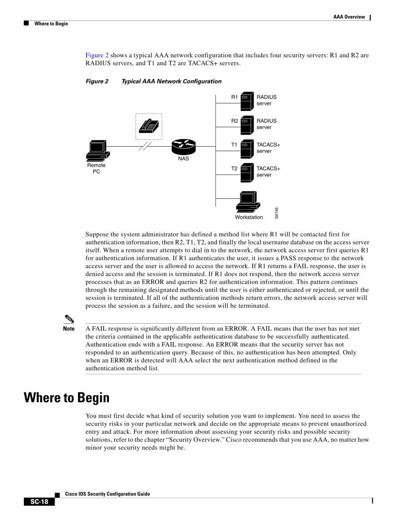
AAA OverviewWhere to Begin
SC-18Cisco IOS Security Configuration Guide
Figure 2 shows a typical AAA network configuration that includes four security servers: R1 and R2 are RADIUS servers, and T1 and T2 are TACACS+ servers.
Figure 2 Typical AAA Network Configuration
Suppose the system administrator has defined a method list where R1 will be contacted first for authentication information, then R2, T1, T2, and finally the local username database on the access server itself. When a remote user attempts to dial in to the network, the network access server first queries R1 for authentication information. If R1 authenticates the user, it issues a PASS response to the network access server and the user is allowed to access the network. If R1 returns a FAIL response, the user is denied access and the session is terminated. If R1 does not respond, then the network access server processes that as an ERROR and queries R2 for authentication information. This pattern continues through the remaining designated methods until the user is either authenticated or rejected, or until the session is terminated. If all of the authentication methods return errors, the network access server will process the session as a failure, and the session will be terminated.
Note A FAIL response is significantly different from an ERROR. A FAIL means that the user has not met the criteria contained in the applicable authentication database to be successfully authenticated. Authentication ends with a FAIL response. An ERROR means that the security server has not responded to an authentication query. Because of this, no authentication has been attempted. Only when an ERROR is detected will AAA select the next authentication method defined in the authentication method list.
Where to BeginYou must first decide what kind of security solution you want to implement. You need to assess the security risks in your particular network and decide on the appropriate means to prevent unauthorized entry and attack. For more information about assessing your security risks and possible security solutions, refer to the chapter “Security Overview.” Cisco recommends that you use AAA, no matter how minor your security needs might be.
S67
46
RADIUSserver
RADIUSserver
TACACS+server
TACACS+server
R1
R2
T1
T2
NASRemote
PC
Workstation
AAA OverviewWhere to Begin
SC-19Cisco IOS Security Configuration Guide
This section includes the following subsections:
• Overview of the AAA Configuration Process
• Enabling AAA
• Disabling AAA
Overview of the AAA Configuration ProcessConfiguring AAA is relatively simple after you understand the basic process involved. To configure security on a Cisco router or access server using AAA, follow this process:
1. Enable AAA by using the aaa new-model global configuration command.
2. If you decide to use a separate security server, configure security protocol parameters, such as RADIUS, TACACS+, or Kerberos.
3. Define the method lists for authentication by using an AAA authentication command.
4. Apply the method lists to a particular interface or line, if required.
5. (Optional) Configure authorization using the aaa authorization command.
6. (Optional) Configure accounting using the aaa accounting command.
For a complete description of the commands used in this chapter, refer to the chapter “Authentication Commands” of the Cisco IOS Security Command Reference. To locate documentation of other commands that appear in this chapter, use the command reference master index or search online.
Enabling AAABefore you can use any of the services AAA network security services provide, you must enable AAA.
Note When you enable AAA, you can no longer access the commands to configure the older protocols, TACACS or extended TACACS. If you decided to use TACACS or extended TACACS in your security solution, do not enable AAA.
To enable AAA, use the following command in global configuration mode:
Command PurposeRouter (config)# aaa new-model Enables AAA.
AAA OverviewWhat to Do Next
SC-20Cisco IOS Security Configuration Guide
Disabling AAAYou can disable AAA functionality with a single command if you decide that your security needs cannot be met by AAA but can be met by using TACACS, extended TACACS, or a line security method that can be implemented without AAA. To disable AAA, use the following command in global configuration mode:
What to Do NextOnce you have enabled AAA, you are ready to configure the other elements relating to your selected security solution. Table 3 describes AAA configuration tasks and where to find more information.
If you have elected not to use the AAA security services, see the “Configuring Authentication” chapter for the non-AAA configuration task “Configuring Login Authentication.”
Command Purpose
Router(config)# no aaa new-model Disables AAA.
Table 3 AAA Access Control Security Solutions Methods
TaskChapter in the Cisco IOS Security Configuration Guide
Configuring local login authentication “Configuring Authentication”
Controlling login using security server authentication “Configuring Authentication”
Defining method lists for authentication “Configuring Authentication”
Applying method lists to a particular interface or line “Configuring Authentication”
Configuring RADIUS security protocol parameters “Configuring RADIUS”
Configuring TACACS+ security protocol parameters “Configuring TACACS+”
Configuring Kerberos security protocol parameters “Configuring Kerberos”
Enabling TACACS+ authorization “Configuring Authorization”
Enabling RADIUS authorization “Configuring Authorization”
Viewing supported IETF RADIUS attributes “RADIUS Attributes” (Appendix)
Viewing supported vendor-specific RADIUS attributes “RADIUS Attributes” (Appendix)
Viewing supported TACACS+ AV pairs “TACACS+ AV Pairs” (Appendix)
Enabling accounting “Configuring Accounting”
SC-21Cisco IOS Security Configuration Guide
Configuring Authentication
Authentication verifies users before they are allowed access to the network and network services. The Cisco IOS software implementation of authentication is divided into two main categories:
• AAA Authentication Methods Configuration Task List
• Non-AAA Authentication Methods
Authentication, for the most part, is implemented through the AAA security services. Cisco recommends that, whenever possible, AAA be used to implement authentication.
This chapter describes both AAA and non-AAA authentication methods. For authentication configuration examples, refer to the “Authentication Examples” section at the end of this chapter. For a complete description of the AAA commands used in this chapter, refer to the “Authentication, Authorization, and Accounting (AAA)” part of the Cisco IOS Security Command Reference. To locate documentation of other commands that appear in this chapter, use the command reference master index or search online.
To identify the hardware platform or software image information associated with a feature, use the Feature Navigator on Cisco.com to search for information about the feature, or refer to the software release notes for a specific release. For more information, see the section “Identifying Supported Platforms” in the chapter “Using Cisco IOS Software.”
In This ChapterThis chapter contains the following sections:
• Named Method Lists for Authentication
• AAA Authentication Methods Configuration Task List
• Non-AAA Authentication Methods
• Authentication Examples
Named Method Lists for AuthenticationTo configure AAA authentication, you must first define a named list of authentication methods, and then apply that list to various interfaces. The method list defines the types of authentication to be performed and the sequence in which they will be performed; it must be applied to a specific interface before any
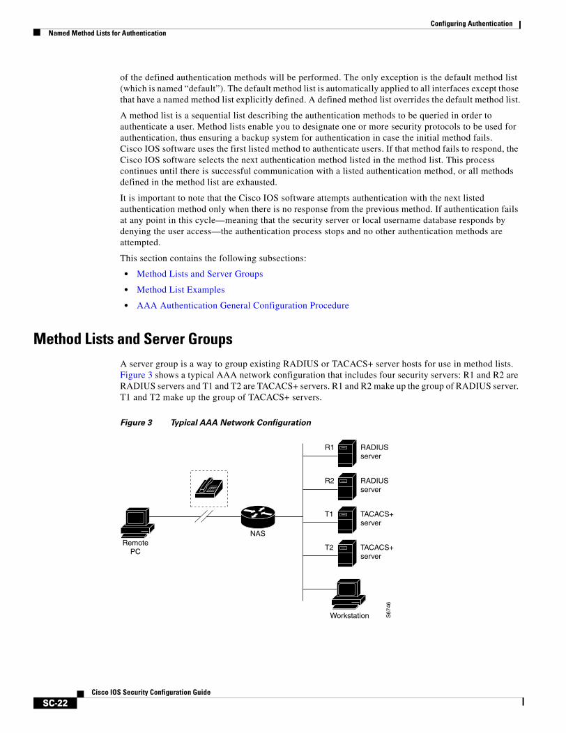
Configuring AuthenticationNamed Method Lists for Authentication
SC-22Cisco IOS Security Configuration Guide
of the defined authentication methods will be performed. The only exception is the default method list (which is named “default”). The default method list is automatically applied to all interfaces except those that have a named method list explicitly defined. A defined method list overrides the default method list.
A method list is a sequential list describing the authentication methods to be queried in order to authenticate a user. Method lists enable you to designate one or more security protocols to be used for authentication, thus ensuring a backup system for authentication in case the initial method fails. Cisco IOS software uses the first listed method to authenticate users. If that method fails to respond, the Cisco IOS software selects the next authentication method listed in the method list. This process continues until there is successful communication with a listed authentication method, or all methods defined in the method list are exhausted.
It is important to note that the Cisco IOS software attempts authentication with the next listed authentication method only when there is no response from the previous method. If authentication fails at any point in this cycle—meaning that the security server or local username database responds by denying the user access—the authentication process stops and no other authentication methods are attempted.
This section contains the following subsections:
• Method Lists and Server Groups
• Method List Examples
• AAA Authentication General Configuration Procedure
Method Lists and Server GroupsA server group is a way to group existing RADIUS or TACACS+ server hosts for use in method lists. Figure 3 shows a typical AAA network configuration that includes four security servers: R1 and R2 are RADIUS servers and T1 and T2 are TACACS+ servers. R1 and R2 make up the group of RADIUS server. T1 and T2 make up the group of TACACS+ servers.
Figure 3 Typical AAA Network Configuration
S67
46
RADIUSserver
RADIUSserver
TACACS+server
TACACS+server
R1
R2
T1
T2
NASRemote
PC
Workstation
Configuring AuthenticationNamed Method Lists for Authentication
SC-23Cisco IOS Security Configuration Guide
Using server groups, you can specify a subset of the configured server hosts and use them for a particular service. For example, server groups allow you to define R1 and R2 as a server group, and define T1 and T2 as a separate server group. For example, you can specify R1 and T1 in the method list for authentication login, while specifying R2 and T2 in the method list for PPP authentication.
Server groups also can include multiple host entries for the same server, as long as each entry has a unique identifier. The combination of an IP address and a UDP port number creates a unique identifier, allowing different ports to be individually defined as RADIUS hosts providing a specific AAA service. In other words, this unique identifier enables RADIUS requests to be sent to different UDP ports on a server at the same IP address. If two different host entries on the same RADIUS server are configured for the same service—for example, authentication—the second host entry configured acts as failover backup to the first one. Using this example, if the first host entry fails to provide accounting services, the network access server will try the second host entry configured on the same device for accounting services. (The RADIUS host entries will be tried in the order in which they are configured.)
For more information about configuring server groups and about configuring server groups based on Dialed Number Identification Service (DNIS) numbers, refer to the “Configuring RADIUS” or “Configuring TACACS+” chapter.
Method List ExamplesSuppose the system administrator has decided on a security solution where all interfaces will use the same authentication methods to authenticate PPP connections. In the RADIUS group, R1 is contacted first for authentication information, then if there is no response, R2 is contacted. If R2 does not respond, T1 in the TACACS+ group is contacted; if T1 does not respond, T2 is contacted. If all designated servers fail to respond, authentication falls to the local username database on the access server itself. To implement this solution, the system administrator would create a default method list by entering the following command:
aaa authentication ppp default group radius group tacacs+ local
In this example, “default” is the name of the method list. The protocols included in this method list are listed after the name, in the order they are to be queried. The default list is automatically applied to all interfaces.
When a remote user attempts to dial in to the network, the network access server first queries R1 for authentication information. If R1 authenticates the user, it issues a PASS response to the network access server and the user is allowed to access the network. If R1 returns a FAIL response, the user is denied access and the session is terminated. If R1 does not respond, then the network access server processes that as an ERROR and queries R2 for authentication information. This pattern would continue through the remaining designated methods until the user is either authenticated or rejected, or until the session is terminated.
It is important to remember that a FAIL response is significantly different from an ERROR. A FAIL means that the user has not met the criteria contained in the applicable authentication database to be successfully authenticated. Authentication ends with a FAIL response. An ERROR means that the security server has not responded to an authentication query. Because of this, no authentication has been attempted. Only when an ERROR is detected will AAA select the next authentication method defined in the authentication method list.

Configuring AuthenticationAAA Authentication Methods Configuration Task List
SC-24Cisco IOS Security Configuration Guide
Suppose the system administrator wants to apply a method list only to a particular interface or set of interfaces. In this case, the system administrator creates a named method list and then applies this named list to the applicable interfaces. The following example shows how the system administrator can implement an authentication method that will be applied only to interface 3:
aaa authentication ppp default group radius group tacacs+ localaaa authentication ppp apple group radius group tacacs+ local noneinterface async 3ppp authentication chap apple
In this example, “apple” is the name of the method list, and the protocols included in this method list are listed after the name in the order in which they are to be performed. After the method list has been created, it is applied to the appropriate interface. Note that the method list name (apple) in both the AAA and PPP authentication commands must match.
In the following example, the system administrator uses server groups to specify that only R2 and T2 are valid servers for PPP authentication. To do this, the administrator must define specific server groups whose members are R2 (172.16.2.7) and T2 (172.16.2.77), respectively. In this example, the RADIUS server group “rad2only” is defined as follows using the aaa group server command:
aaa group server radius rad2onlyserver 172.16.2.7
The TACACS+ server group “tac2only” is defined as follows using the aaa group server command:
aaa group server tacacs+ tac2onlyserver 172.16.2.77
The administrator then applies PPP authentication using the server groups. In this example, the default methods list for PPP authentication follows this order: group rad2only, group tac2only, and local:
aaa authentication ppp default group rad2only group tac2only local
AAA Authentication General Configuration ProcedureTo configure AAA authentication, perform the following tasks:
1. Enable AAA by using the aaa new-model global configuration command. For more information about configuring AAA, refer to the chapter “AAA Overview”.
2. Configure security protocol parameters, such as RADIUS, TACACS+, or Kerberos if you are using a security server. For more information about RADIUS, refer to the chapter “Configuring RADIUS”. For more information about TACACS+, refer to the chapter “Configuring TACACS+”. For more information about Kerberos, refer to the chapter “Configuring Kerberos”.
3. Define the method lists for authentication by using an AAA authentication command.
4. Apply the method lists to a particular interface or line, if required.
AAA Authentication Methods Configuration Task ListThis section discusses the following AAA authentication methods:
• Configuring Login Authentication Using AAA
• Configuring PPP Authentication Using AAA
• Configuring AAA Scalability for PPP Requests
• Configuring ARAP Authentication Using AAA
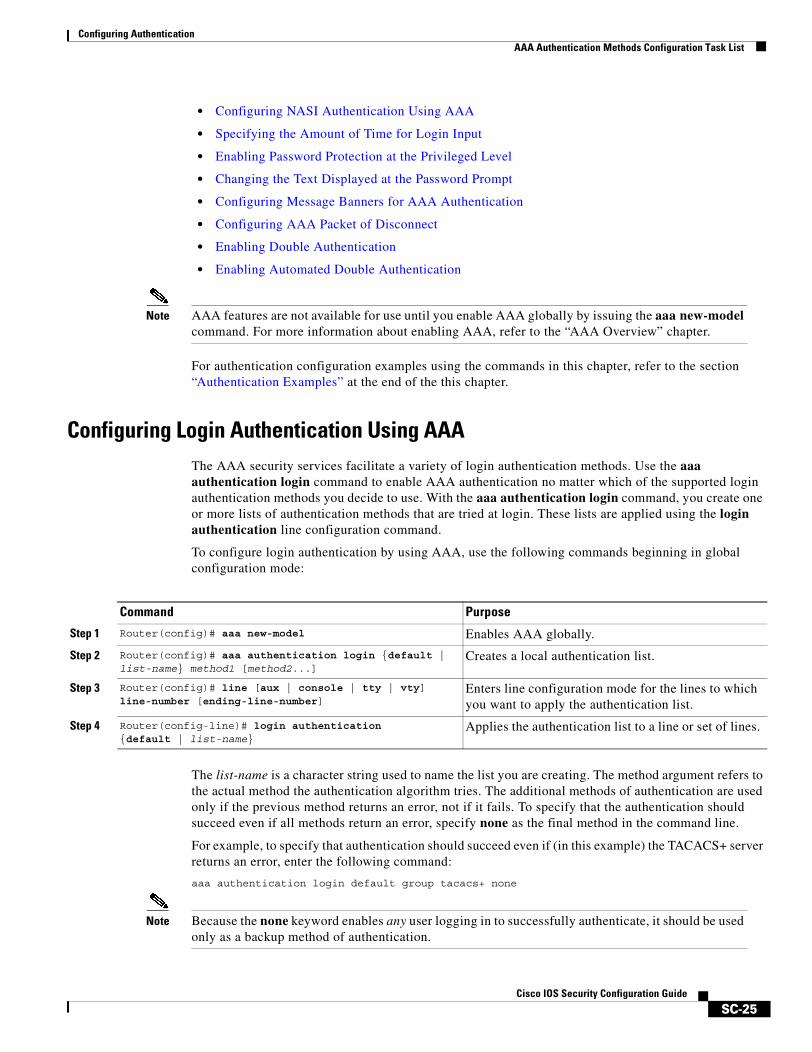
Configuring AuthenticationAAA Authentication Methods Configuration Task List
SC-25Cisco IOS Security Configuration Guide
• Configuring NASI Authentication Using AAA
• Specifying the Amount of Time for Login Input
• Enabling Password Protection at the Privileged Level
• Changing the Text Displayed at the Password Prompt
• Configuring Message Banners for AAA Authentication
• Configuring AAA Packet of Disconnect
• Enabling Double Authentication
• Enabling Automated Double Authentication
Note AAA features are not available for use until you enable AAA globally by issuing the aaa new-model command. For more information about enabling AAA, refer to the “AAA Overview” chapter.
For authentication configuration examples using the commands in this chapter, refer to the section “Authentication Examples” at the end of the this chapter.
Configuring Login Authentication Using AAAThe AAA security services facilitate a variety of login authentication methods. Use the aaa authentication login command to enable AAA authentication no matter which of the supported login authentication methods you decide to use. With the aaa authentication login command, you create one or more lists of authentication methods that are tried at login. These lists are applied using the login authentication line configuration command.
To configure login authentication by using AAA, use the following commands beginning in global configuration mode:
The list-name is a character string used to name the list you are creating. The method argument refers to the actual method the authentication algorithm tries. The additional methods of authentication are used only if the previous method returns an error, not if it fails. To specify that the authentication should succeed even if all methods return an error, specify none as the final method in the command line.
For example, to specify that authentication should succeed even if (in this example) the TACACS+ server returns an error, enter the following command:
aaa authentication login default group tacacs+ none
Note Because the none keyword enables any user logging in to successfully authenticate, it should be used only as a backup method of authentication.
Command Purpose
Step 1 Router(config)# aaa new-model Enables AAA globally.
Step 2 Router(config)# aaa authentication login {default | list-name} method1 [method2...]
Creates a local authentication list.
Step 3 Router(config)# line [aux | console | tty | vty] line-number [ending-line-number]
Enters line configuration mode for the lines to which you want to apply the authentication list.
Step 4 Router(config-line)# login authentication {default | list-name}
Applies the authentication list to a line or set of lines.
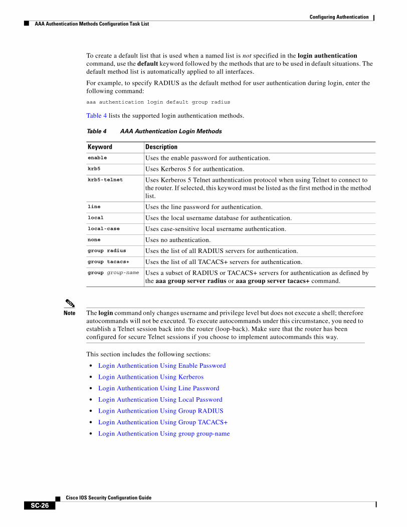
Configuring AuthenticationAAA Authentication Methods Configuration Task List
SC-26Cisco IOS Security Configuration Guide
To create a default list that is used when a named list is not specified in the login authentication command, use the default keyword followed by the methods that are to be used in default situations. The default method list is automatically applied to all interfaces.
For example, to specify RADIUS as the default method for user authentication during login, enter the following command:
aaa authentication login default group radius
Table 4 lists the supported login authentication methods.
Note The login command only changes username and privilege level but does not execute a shell; therefore autocommands will not be executed. To execute autocommands under this circumstance, you need to establish a Telnet session back into the router (loop-back). Make sure that the router has been configured for secure Telnet sessions if you choose to implement autocommands this way.
This section includes the following sections:
• Login Authentication Using Enable Password
• Login Authentication Using Kerberos
• Login Authentication Using Line Password
• Login Authentication Using Local Password
• Login Authentication Using Group RADIUS
• Login Authentication Using Group TACACS+
• Login Authentication Using group group-name
Table 4 AAA Authentication Login Methods
Keyword Description
enable Uses the enable password for authentication.
krb5 Uses Kerberos 5 for authentication.
krb5-telnet Uses Kerberos 5 Telnet authentication protocol when using Telnet to connect to the router. If selected, this keyword must be listed as the first method in the method list.
line Uses the line password for authentication.
local Uses the local username database for authentication.
local-case Uses case-sensitive local username authentication.
none Uses no authentication.
group radius Uses the list of all RADIUS servers for authentication.
group tacacs+ Uses the list of all TACACS+ servers for authentication.
group group-name Uses a subset of RADIUS or TACACS+ servers for authentication as defined by the aaa group server radius or aaa group server tacacs+ command.

Configuring AuthenticationAAA Authentication Methods Configuration Task List
SC-27Cisco IOS Security Configuration Guide
Login Authentication Using Enable Password
Use the aaa authentication login command with the enable method keyword to specify the enable password as the login authentication method. For example, to specify the enable password as the method of user authentication at login when no other method list has been defined, enter the following command:
aaa authentication login default enable
Before you can use the enable password as the login authentication method, you need to define the enable password. For more information about defining enable passwords, refer to the chapter “Configuring Passwords and Privileges.”
Login Authentication Using Kerberos
Authentication via Kerberos is different from most other authentication methods: the user’s password is never sent to the remote access server. Remote users logging in to the network are prompted for a username. If the key distribution center (KDC) has an entry for that user, it creates an encrypted ticket granting ticket (TGT) with the password for that user and sends it back to the router. The user is then prompted for a password, and the router attempts to decrypt the TGT with that password. If it succeeds, the user is authenticated and the TGT is stored in the user’s credential cache on the router.
While krb5 does use the KINIT program, a user does not need to run the KINIT program to get a TGT to authenticate to the router. This is because KINIT has been integrated into the login procedure in the Cisco IOS implementation of Kerberos.
Use the aaa authentication login command with the krb5 method keyword to specify Kerberos as the login authentication method. For example, to specify Kerberos as the method of user authentication at login when no other method list has been defined, enter the following command:
aaa authentication login default krb5
Before you can use Kerberos as the login authentication method, you need to enable communication with the Kerberos security server. For more information about establishing communication with a Kerberos server, refer to the chapter “Configuring Kerberos.”
Login Authentication Using Line Password
Use the aaa authentication login command with the line method keyword to specify the line password as the login authentication method. For example, to specify the line password as the method of user authentication at login when no other method list has been defined, enter the following command:
aaa authentication login default line
Before you can use a line password as the login authentication method, you need to define a line password. For more information about defining line passwords, refer to the section “Configuring Line Password Protection” in this chapter.
Login Authentication Using Local Password
Use the aaa authentication login command with the local method keyword to specify that the Cisco router or access server will use the local username database for authentication. For example, to specify the local username database as the method of user authentication at login when no other method list has been defined, enter the following command:
aaa authentication login default local
For information about adding users into the local username database, refer to the section “Establishing Username Authentication” in this chapter.
Configuring AuthenticationAAA Authentication Methods Configuration Task List
SC-28Cisco IOS Security Configuration Guide
Login Authentication Using Group RADIUS
Use the aaa authentication login command with the group radius method to specify RADIUS as the login authentication method. For example, to specify RADIUS as the method of user authentication at login when no other method list has been defined, enter the following command:
aaa authentication login default group radius
Before you can use RADIUS as the login authentication method, you need to enable communication with the RADIUS security server. For more information about establishing communication with a RADIUS server, refer to the chapter “Configuring RADIUS.”
Configuring RADIUS Attribute 8 in Access Requests
Once you have used the aaa authentication login command to specify RADIUS and your login host has been configured to request its IP address from the NAS, you can send attribute 8 (Framed-IP-Address) in access-request packets by using the radius-server attribute 8 include-in-access-req command in global configuration mode. This command makes it possible for a NAS to provide the RADIUS server with a hint of the user IP address in advance of user authentication. For more information about attribute 8, refer to the appendix “RADIUS Attributes” at the end of the book.
Login Authentication Using Group TACACS+
Use the aaa authentication login command with the group tacacs+ method to specify TACACS+ as the login authentication method. For example, to specify TACACS+ as the method of user authentication at login when no other method list has been defined, enter the following command:
aaa authentication login default group tacacs+
Before you can use TACACS+ as the login authentication method, you need to enable communication with the TACACS+ security server. For more information about establishing communication with a TACACS+ server, refer to the chapter “Configuring TACACS+.”
Login Authentication Using group group-name
Use the aaa authentication login command with the group group-name method to specify a subset of RADIUS or TACACS+ servers to use as the login authentication method. To specify and define the group name and the members of the group, use the aaa group server command. For example, use the aaa group server command to first define the members of group loginrad:
aaa group server radius loginradserver 172.16.2.3server 172.16.2 17server 172.16.2.32
This command specifies RADIUS servers 172.16.2.3, 172.16.2.17, and 172.16.2.32 as members of the group loginrad.
To specify group loginrad as the method of user authentication at login when no other method list has been defined, enter the following command:
aaa authentication login default group loginrad
Before you can use a group name as the login authentication method, you need to enable communication with the RADIUS or TACACS+ security server. For more information about establishing communication with a RADIUS server, refer to the chapter “Configuring RADIUS.” For more information about establishing communication with a TACACS+ server, refer to the chapter “Configuring TACACS+.”
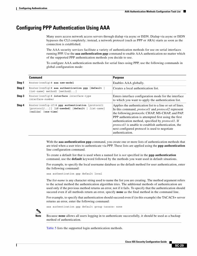
Configuring AuthenticationAAA Authentication Methods Configuration Task List
SC-29Cisco IOS Security Configuration Guide
Configuring PPP Authentication Using AAAMany users access network access servers through dialup via async or ISDN. Dialup via async or ISDN bypasses the CLI completely; instead, a network protocol (such as PPP or ARA) starts as soon as the connection is established.
The AAA security services facilitate a variety of authentication methods for use on serial interfaces running PPP. Use the aaa authentication ppp command to enable AAA authentication no matter which of the supported PPP authentication methods you decide to use.
To configure AAA authentication methods for serial lines using PPP, use the following commands in global configuration mode:
With the aaa authentication ppp command, you create one or more lists of authentication methods that are tried when a user tries to authenticate via PPP. These lists are applied using the ppp authentication line configuration command.
To create a default list that is used when a named list is not specified in the ppp authentication command, use the default keyword followed by the methods you want used in default situations.
For example, to specify the local username database as the default method for user authentication, enter the following command:
aaa authentication ppp default local
The list-name is any character string used to name the list you are creating. The method argument refers to the actual method the authentication algorithm tries. The additional methods of authentication are used only if the previous method returns an error, not if it fails. To specify that the authentication should succeed even if all methods return an error, specify none as the final method in the command line.
For example, to specify that authentication should succeed even if (in this example) the TACACS+ server returns an error, enter the following command:
aaa authentication ppp default group tacacs+ none
Note Because none allows all users logging in to authenticate successfully, it should be used as a backup method of authentication.
Table 5 lists the supported login authentication methods.
Command Purpose
Step 1 Router(config)# aaa new-model Enables AAA globally.
Step 2 Router(config)# aaa authentication ppp {default | list-name} method1 [method2...]
Creates a local authentication list.
Step 3 Router(config)# interface interface-type interface-number
Enters interface configuration mode for the interface to which you want to apply the authentication list.
Step 4 Router(config-if)# ppp authentication {protocol1 [protocol2...]} [if-needed] {default | list-name} [callin] [one-time]
Applies the authentication list to a line or set of lines. In this command, protocol1 and protocol2 represent the following protocols: CHAP, MS-CHAP, and PAP. PPP authentication is attempted first using the first authentication method, specified by protocol1. If protocol1 is unable to establish authentication, the next configured protocol is used to negotiate authentication.
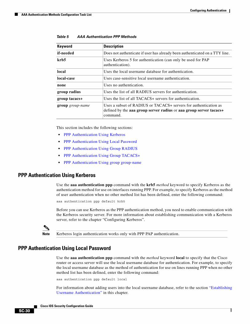
Configuring AuthenticationAAA Authentication Methods Configuration Task List
SC-30Cisco IOS Security Configuration Guide
This section includes the following sections:
• PPP Authentication Using Kerberos
• PPP Authentication Using Local Password
• PPP Authentication Using Group RADIUS
• PPP Authentication Using Group TACACS+
• PPP Authentication Using group group-name
PPP Authentication Using Kerberos
Use the aaa authentication ppp command with the krb5 method keyword to specify Kerberos as the authentication method for use on interfaces running PPP. For example, to specify Kerberos as the method of user authentication when no other method list has been defined, enter the following command:
aaa authentication ppp default krb5
Before you can use Kerberos as the PPP authentication method, you need to enable communication with the Kerberos security server. For more information about establishing communication with a Kerberos server, refer to the chapter “Configuring Kerberos”.
Note Kerberos login authentication works only with PPP PAP authentication.
PPP Authentication Using Local Password
Use the aaa authentication ppp command with the method keyword local to specify that the Cisco router or access server will use the local username database for authentication. For example, to specify the local username database as the method of authentication for use on lines running PPP when no other method list has been defined, enter the following command:
aaa authentication ppp default local
For information about adding users into the local username database, refer to the section “Establishing Username Authentication” in this chapter.
Table 5 AAA Authentication PPP Methods
Keyword Description
if-needed Does not authenticate if user has already been authenticated on a TTY line.
krb5 Uses Kerberos 5 for authentication (can only be used for PAP authentication).
local Uses the local username database for authentication.
local-case Uses case-sensitive local username authentication.
none Uses no authentication.
group radius Uses the list of all RADIUS servers for authentication.
group tacacs+ Uses the list of all TACACS+ servers for authentication.
group group-name Uses a subset of RADIUS or TACACS+ servers for authentication as defined by the aaa group server radius or aaa group server tacacs+ command.
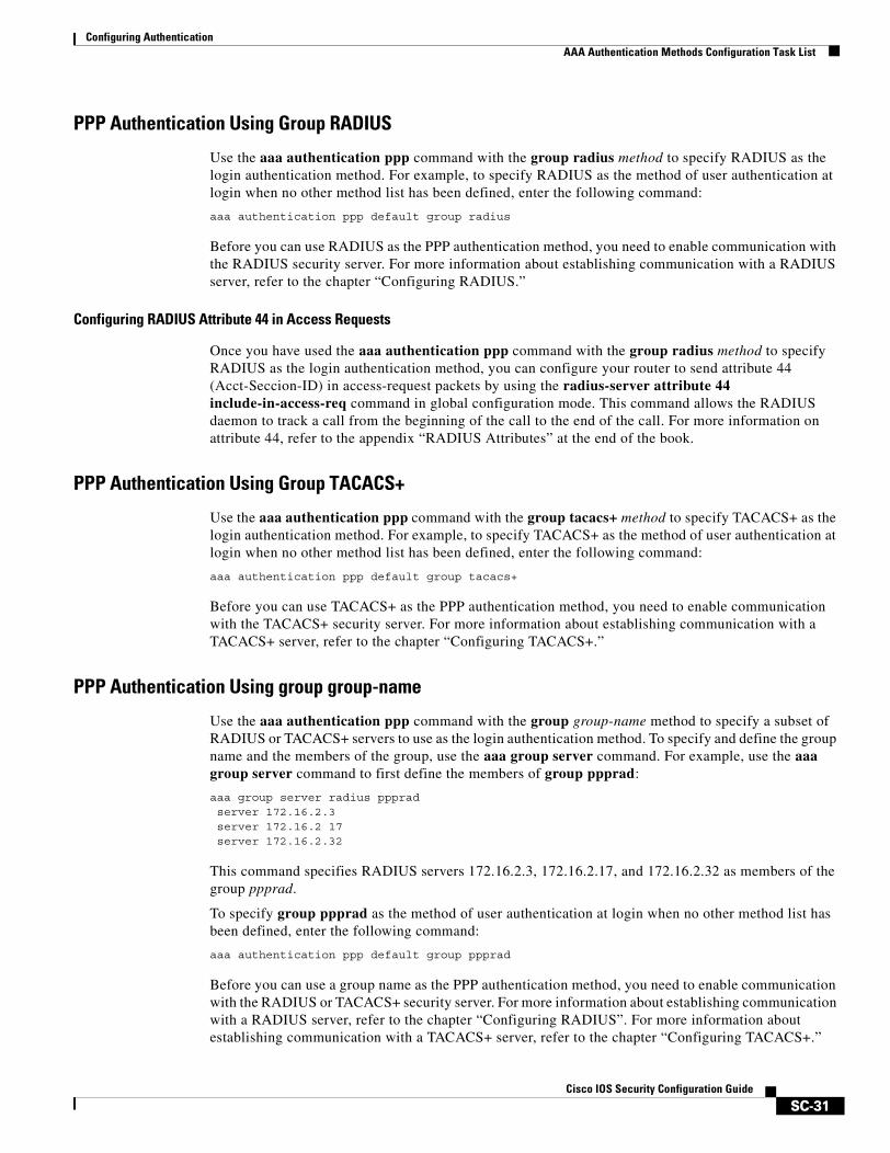
Configuring AuthenticationAAA Authentication Methods Configuration Task List
SC-31Cisco IOS Security Configuration Guide
PPP Authentication Using Group RADIUS
Use the aaa authentication ppp command with the group radius method to specify RADIUS as the login authentication method. For example, to specify RADIUS as the method of user authentication at login when no other method list has been defined, enter the following command:
aaa authentication ppp default group radius
Before you can use RADIUS as the PPP authentication method, you need to enable communication with the RADIUS security server. For more information about establishing communication with a RADIUS server, refer to the chapter “Configuring RADIUS.”
Configuring RADIUS Attribute 44 in Access Requests
Once you have used the aaa authentication ppp command with the group radius method to specify RADIUS as the login authentication method, you can configure your router to send attribute 44 (Acct-Seccion-ID) in access-request packets by using the radius-server attribute 44 include-in-access-req command in global configuration mode. This command allows the RADIUS daemon to track a call from the beginning of the call to the end of the call. For more information on attribute 44, refer to the appendix “RADIUS Attributes” at the end of the book.
PPP Authentication Using Group TACACS+
Use the aaa authentication ppp command with the group tacacs+ method to specify TACACS+ as the login authentication method. For example, to specify TACACS+ as the method of user authentication at login when no other method list has been defined, enter the following command:
aaa authentication ppp default group tacacs+
Before you can use TACACS+ as the PPP authentication method, you need to enable communication with the TACACS+ security server. For more information about establishing communication with a TACACS+ server, refer to the chapter “Configuring TACACS+.”
PPP Authentication Using group group-name
Use the aaa authentication ppp command with the group group-name method to specify a subset of RADIUS or TACACS+ servers to use as the login authentication method. To specify and define the group name and the members of the group, use the aaa group server command. For example, use the aaa group server command to first define the members of group ppprad:
aaa group server radius pppradserver 172.16.2.3server 172.16.2 17server 172.16.2.32
This command specifies RADIUS servers 172.16.2.3, 172.16.2.17, and 172.16.2.32 as members of the group ppprad.
To specify group ppprad as the method of user authentication at login when no other method list has been defined, enter the following command:
aaa authentication ppp default group ppprad
Before you can use a group name as the PPP authentication method, you need to enable communication with the RADIUS or TACACS+ security server. For more information about establishing communication with a RADIUS server, refer to the chapter “Configuring RADIUS”. For more information about establishing communication with a TACACS+ server, refer to the chapter “Configuring TACACS+.”
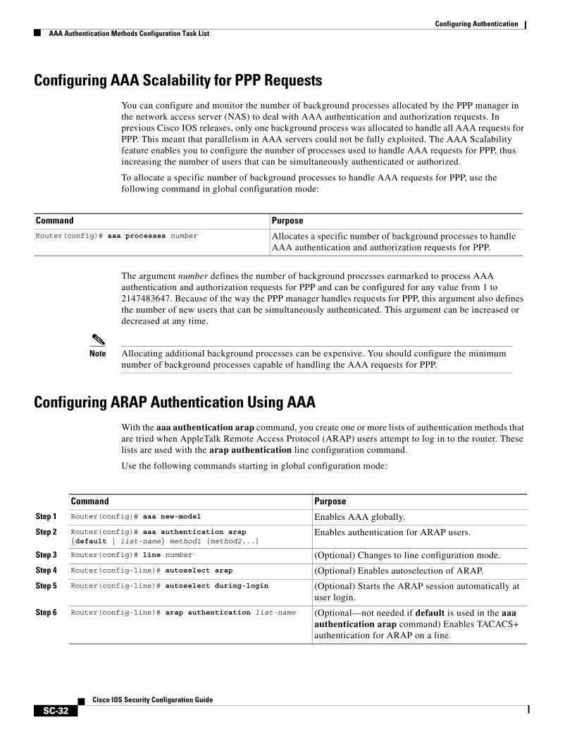
Configuring AuthenticationAAA Authentication Methods Configuration Task List
SC-32Cisco IOS Security Configuration Guide
Configuring AAA Scalability for PPP RequestsYou can configure and monitor the number of background processes allocated by the PPP manager in the network access server (NAS) to deal with AAA authentication and authorization requests. In previous Cisco IOS releases, only one background process was allocated to handle all AAA requests for PPP. This meant that parallelism in AAA servers could not be fully exploited. The AAA Scalability feature enables you to configure the number of processes used to handle AAA requests for PPP, thus increasing the number of users that can be simultaneously authenticated or authorized.
To allocate a specific number of background processes to handle AAA requests for PPP, use the following command in global configuration mode:
The argument number defines the number of background processes earmarked to process AAA authentication and authorization requests for PPP and can be configured for any value from 1 to 2147483647. Because of the way the PPP manager handles requests for PPP, this argument also defines the number of new users that can be simultaneously authenticated. This argument can be increased or decreased at any time.
Note Allocating additional background processes can be expensive. You should configure the minimum number of background processes capable of handling the AAA requests for PPP.
Configuring ARAP Authentication Using AAAWith the aaa authentication arap command, you create one or more lists of authentication methods that are tried when AppleTalk Remote Access Protocol (ARAP) users attempt to log in to the router. These lists are used with the arap authentication line configuration command.
Use the following commands starting in global configuration mode:
Command Purpose
Router(config)# aaa processes number Allocates a specific number of background processes to handle AAA authentication and authorization requests for PPP.
Command Purpose
Step 1 Router(config)# aaa new-model Enables AAA globally.
Step 2 Router(config)# aaa authentication arap {default | list-name} method1 [method2...]
Enables authentication for ARAP users.
Step 3 Router(config)# line number (Optional) Changes to line configuration mode.
Step 4 Router(config-line)# autoselect arap (Optional) Enables autoselection of ARAP.
Step 5 Router(config-line)# autoselect during-login (Optional) Starts the ARAP session automatically at user login.
Step 6 Router(config-line)# arap authentication list-name (Optional—not needed if default is used in the aaa authentication arap command) Enables TACACS+ authentication for ARAP on a line.
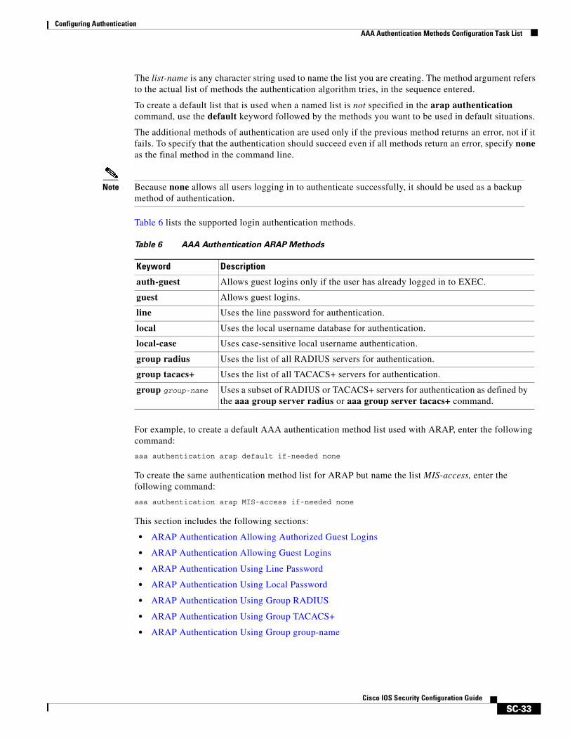
Configuring AuthenticationAAA Authentication Methods Configuration Task List
SC-33Cisco IOS Security Configuration Guide
The list-name is any character string used to name the list you are creating. The method argument refers to the actual list of methods the authentication algorithm tries, in the sequence entered.
To create a default list that is used when a named list is not specified in the arap authentication command, use the default keyword followed by the methods you want to be used in default situations.
The additional methods of authentication are used only if the previous method returns an error, not if it fails. To specify that the authentication should succeed even if all methods return an error, specify none as the final method in the command line.
Note Because none allows all users logging in to authenticate successfully, it should be used as a backup method of authentication.
Table 6 lists the supported login authentication methods.
For example, to create a default AAA authentication method list used with ARAP, enter the following command:
aaa authentication arap default if-needed none
To create the same authentication method list for ARAP but name the list MIS-access, enter the following command:
aaa authentication arap MIS-access if-needed none
This section includes the following sections:
• ARAP Authentication Allowing Authorized Guest Logins
• ARAP Authentication Allowing Guest Logins
• ARAP Authentication Using Line Password
• ARAP Authentication Using Local Password
• ARAP Authentication Using Group RADIUS
• ARAP Authentication Using Group TACACS+
• ARAP Authentication Using Group group-name
Table 6 AAA Authentication ARAP Methods
Keyword Description
auth-guest Allows guest logins only if the user has already logged in to EXEC.
guest Allows guest logins.
line Uses the line password for authentication.
local Uses the local username database for authentication.
local-case Uses case-sensitive local username authentication.
group radius Uses the list of all RADIUS servers for authentication.
group tacacs+ Uses the list of all TACACS+ servers for authentication.
group group-name Uses a subset of RADIUS or TACACS+ servers for authentication as defined by the aaa group server radius or aaa group server tacacs+ command.

Configuring AuthenticationAAA Authentication Methods Configuration Task List
SC-34Cisco IOS Security Configuration Guide
ARAP Authentication Allowing Authorized Guest Logins
Use the aaa authentication arap command with the auth-guest keyword to allow guest logins only if the user has already successfully logged in to the EXEC. This method must be the first listed in the ARAP authentication method list but it can be followed by other methods if it does not succeed. For example, to allow all authorized guest logins—meaning logins by users who have already successfully logged in to the EXEC—as the default method of authentication, using RADIUS only if that method fails, enter the following command:
aaa authentication arap default auth-guest group radius
For more information about ARAP authorized guest logins, refer to the chapter “Configuring AppleTalk” in the Cisco IOS AppleTalk and Novell IPX Configuration Guide.
Note By default, guest logins through ARAP are disabled when you initialize AAA. To allow guest logins, you must use the aaa authentication arap command with either the guest or the auth-guest keyword.
ARAP Authentication Allowing Guest Logins
Use the aaa authentication arap command with the guest keyword to allow guest logins. This method must be the first listed in the ARAP authentication method list but it can be followed by other methods if it does not succeed. For example, to allow all guest logins as the default method of authentication, using RADIUS only if that method fails, enter the following command:
aaa authentication arap default guest group radius
For more information about ARAP guest logins, refer to the chapter “Configuring AppleTalk” in the Cisco IOS AppleTalk and Novell IPX Configuration Guide.
ARAP Authentication Using Line Password
Use the aaa authentication arap command with the method keyword line to specify the line password as the authentication method. For example, to specify the line password as the method of ARAP user authentication when no other method list has been defined, enter the following command:
aaa authentication arap default line
Before you can use a line password as the ARAP authentication method, you need to define a line password. For more information about defining line passwords, refer to the section “Configuring Line Password Protection” in this chapter.
ARAP Authentication Using Local Password
Use the aaa authentication arap command with the method keyword local to specify that the Cisco router or access server will use the local username database for authentication. For example, to specify the local username database as the method of ARAP user authentication when no other method list has been defined, enter the following command:
aaa authentication arap default local
For information about adding users to the local username database, refer to the section “Establishing Username Authentication” in this chapter.
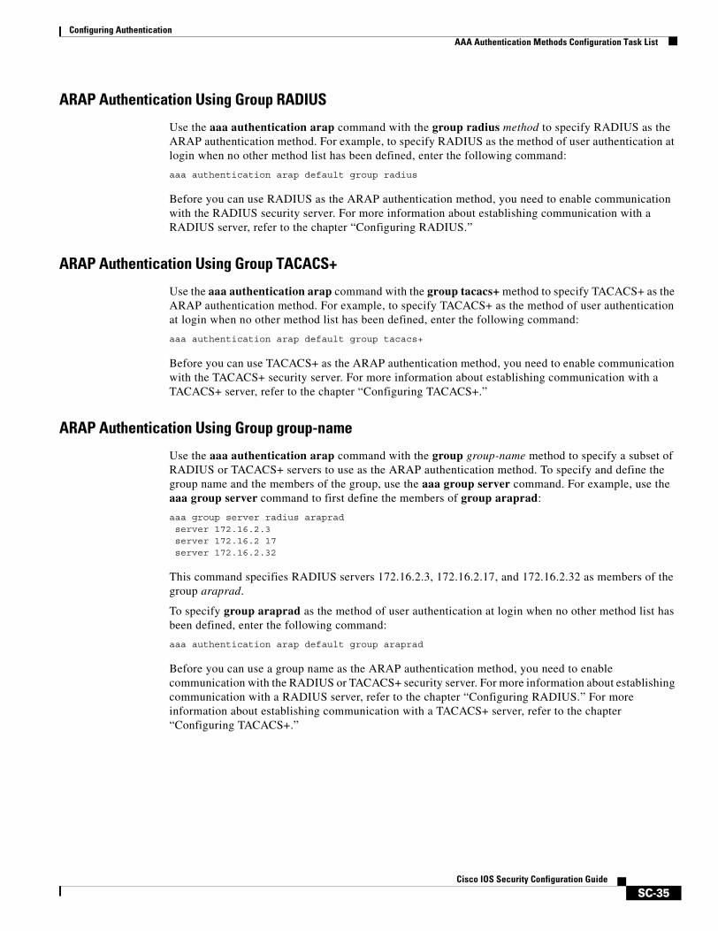
Configuring AuthenticationAAA Authentication Methods Configuration Task List
SC-35Cisco IOS Security Configuration Guide
ARAP Authentication Using Group RADIUS
Use the aaa authentication arap command with the group radius method to specify RADIUS as the ARAP authentication method. For example, to specify RADIUS as the method of user authentication at login when no other method list has been defined, enter the following command:
aaa authentication arap default group radius
Before you can use RADIUS as the ARAP authentication method, you need to enable communication with the RADIUS security server. For more information about establishing communication with a RADIUS server, refer to the chapter “Configuring RADIUS.”
ARAP Authentication Using Group TACACS+
Use the aaa authentication arap command with the group tacacs+ method to specify TACACS+ as the ARAP authentication method. For example, to specify TACACS+ as the method of user authentication at login when no other method list has been defined, enter the following command:
aaa authentication arap default group tacacs+
Before you can use TACACS+ as the ARAP authentication method, you need to enable communication with the TACACS+ security server. For more information about establishing communication with a TACACS+ server, refer to the chapter “Configuring TACACS+.”
ARAP Authentication Using Group group-name
Use the aaa authentication arap command with the group group-name method to specify a subset of RADIUS or TACACS+ servers to use as the ARAP authentication method. To specify and define the group name and the members of the group, use the aaa group server command. For example, use the aaa group server command to first define the members of group araprad:
aaa group server radius arapradserver 172.16.2.3server 172.16.2 17server 172.16.2.32
This command specifies RADIUS servers 172.16.2.3, 172.16.2.17, and 172.16.2.32 as members of the group araprad.
To specify group araprad as the method of user authentication at login when no other method list has been defined, enter the following command:
aaa authentication arap default group araprad
Before you can use a group name as the ARAP authentication method, you need to enable communication with the RADIUS or TACACS+ security server. For more information about establishing communication with a RADIUS server, refer to the chapter “Configuring RADIUS.” For more information about establishing communication with a TACACS+ server, refer to the chapter “Configuring TACACS+.”

Configuring AuthenticationAAA Authentication Methods Configuration Task List
SC-36Cisco IOS Security Configuration Guide
Configuring NASI Authentication Using AAAWith the aaa authentication nasi command, you create one or more lists of authentication methods that are tried when NetWare Asynchronous Services Interface (NASI) users attempt to log in to the router. These lists are used with the nasi authentication line configuration command.
To configure NASI authentication using AAA, use the following commands starting in global configuration mode:
The list-name is any character string used to name the list you are creating. The method argument refers to the actual list of methods the authentication algorithm tries, in the sequence entered.
To create a default list that is used when a named list is not specified in the aaa authentication nasi command, use the default keyword followed by the methods you want to be used in default situations.
The additional methods of authentication are used only if the previous method returns an error, not if it fails. To specify that the authentication should succeed even if all methods return an error, specify none as the final method in the command line.
Note Because none allows all users logging in to authenticate successfully, it should be used as a backup method of authentication.
Table 7 lists the supported NASI authentication methods.
Command Purpose
Step 1 Router(config)# aaa new-model Enables AAA globally.
Step 2 Router(config)# aaa authentication nasi {default | list-name} method1 [method2...]
Enables authentication for NASI users.
Step 3 Router(config)# line number (Optional—not needed if default is used in the aaa authentication nasi command) Enters line configuration mode.
Step 4 Router(config-line)# nasi authentication list-name (Optional—not needed if default is used in the aaa authentication nasi command) Enables authentication for NASI on a line.
Table 7 AAA Authentication NASI Methods
Keyword Description
enable Uses the enable password for authentication.
line Uses the line password for authentication.
local Uses the local username database for authentication.
local-case Uses case-sensitive local username authentication.
none Uses no authentication.
group radius Uses the list of all RADIUS servers for authentication.
group tacacs+ Uses the list of all TACACS+ servers for authentication.
group group-name Uses a subset of RADIUS or TACACS+ servers for authentication as defined by the aaa group server radius or aaa group server tacacs+ command.
Configuring AuthenticationAAA Authentication Methods Configuration Task List
SC-37Cisco IOS Security Configuration Guide
This section includes the following sections:
• NASI Authentication Using Enable Password
• NASI Authentication Using Line Password
• NASI Authentication Using Local Password
• NASI Authentication Using Group RADIUS
• NASI Authentication Using Group TACACS+
• NASI Authentication Using group group-name
NASI Authentication Using Enable Password
Use the aaa authentication nasi command with the method keyword enable to specify the enable password as the authentication method. For example, to specify the enable password as the method of NASI user authentication when no other method list has been defined, enter the following command:
aaa authentication nasi default enable
Before you can use the enable password as the authentication method, you need to define the enable password. For more information about defining enable passwords, refer to the chapter “Configuring Passwords and Privileges.”
NASI Authentication Using Line Password
Use the aaa authentication nasi command with the method keyword line to specify the line password as the authentication method. For example, to specify the line password as the method of NASI user authentication when no other method list has been defined, enter the following command:
aaa authentication nasi default line
Before you can use a line password as the NASI authentication method, you need to define a line password. For more information about defining line passwords, refer to the section “Configuring Line Password Protection” in this chapter.
NASI Authentication Using Local Password
Use the aaa authentication nasi command with the method keyword local to specify that the Cisco router or access server will use the local username database for authentication information. For example, to specify the local username database as the method of NASI user authentication when no other method list has been defined, enter the following command:
aaa authentication nasi default local
For information about adding users to the local username database, refer to the section “Establishing Username Authentication” in this chapter.
Configuring AuthenticationAAA Authentication Methods Configuration Task List
SC-38Cisco IOS Security Configuration Guide
NASI Authentication Using Group RADIUS
Use the aaa authentication nasi command with the group radius method to specify RADIUS as the NASI authentication method. For example, to specify RADIUS as the method of NASI user authentication when no other method list has been defined, enter the following command:
aaa authentication nasi default group radius
Before you can use RADIUS as the NASI authentication method, you need to enable communication with the RADIUS security server. For more information about establishing communication with a RADIUS server, refer to the chapter “Configuring RADIUS.”
NASI Authentication Using Group TACACS+
Use the aaa authentication nasi command with the group tacacs+ method keyword to specify TACACS+ as the NASI authentication method. For example, to specify TACACS+ as the method of NASI user authentication when no other method list has been defined, enter the following command:
aaa authentication nasi default group tacacs+
Before you can use TACACS+ as the authentication method, you need to enable communication with the TACACS+ security server. For more information about establishing communication with a TACACS+ server, refer to the chapter “Configuring TACACS+.”
NASI Authentication Using group group-name
Use the aaa authentication nasi command with the group group-name method to specify a subset of RADIUS or TACACS+ servers to use as the NASI authentication method. To specify and define the group name and the members of the group, use the aaa group server command. For example, use the aaa group server command to first define the members of group nasirad:
aaa group server radius nasiradserver 172.16.2.3server 172.16.2 17server 172.16.2.32
This command specifies RADIUS servers 172.16.2.3, 172.16.2.17, and 172.16.2.32 as members of the group nasirad.
To specify group nasirad as the method of user authentication at login when no other method list has been defined, enter the following command:
aaa authentication nasi default group nasirad
Before you can use a group name as the NASI authentication method, you need to enable communication with the RADIUS or TACACS+ security server. For more information about establishing communication with a RADIUS server, refer to the chapter “Configuring RADIUS”. For more information about establishing communication with a TACACS+ server, refer to the chapter “Configuring TACACS+.”
Configuring AuthenticationAAA Authentication Methods Configuration Task List
SC-39Cisco IOS Security Configuration Guide
Specifying the Amount of Time for Login InputThe timeout login response command allows you to specify how long the system will wait for login input (such as username and password) before timing out. The default login value is 30 seconds; with the timeout login response command, you can specify a timeout value from 1 to 300 seconds. To change the login timeout value from the default of 30 seconds, use the following command in line configuration mode:
Enabling Password Protection at the Privileged LevelUse the aaa authentication enable default command to create a series of authentication methods that are used to determine whether a user can access the privileged EXEC command level. You can specify up to four authentication methods. The additional methods of authentication are used only if the previous method returns an error, not if it fails. To specify that the authentication should succeed even if all methods return an error, specify none as the final method in the command line.
Use the following command in global configuration mode:
The method argument refers to the actual list of methods the authentication algorithm tries, in the sequence entered. Table 8 lists the supported enable authentication methods.
Command Purpose
Router(config-line)# timeout login response seconds Specifies how long the system will wait for login information before timing out.
Command Purpose
Router(config)# aaa authentication enable default method1 [method2...]
Enables user ID and password checking for users requesting privileged EXEC level.
Note All aaa authentication enable default requests sent by the router to a RADIUS server include the username “$enab15$.” Requests sent to a TACACS+ server will include the username that is entered for login authentication.
Table 8 AAA Authentication Enable Default Methods
Keyword Description
enable Uses the enable password for authentication.
line Uses the line password for authentication.
none Uses no authentication.
group radius Uses the list of all RADIUS hosts for authentication.
Note The RADIUS method does not work on a per-username basis.
group tacacs+ Uses the list of all TACACS+ hosts for authentication.
group group-name Uses a subset of RADIUS or TACACS+ servers for authentication as defined by the aaa group server radius or aaa group server tacacs+ command.
Configuring AuthenticationAAA Authentication Methods Configuration Task List
SC-40Cisco IOS Security Configuration Guide
Changing the Text Displayed at the Password PromptUse the aaa authentication password-prompt command to change the default text that the Cisco IOS software displays when prompting a user to enter a password. This command changes the password prompt for the enable password as well as for login passwords that are not supplied by remote security servers. The no form of this command returns the password prompt to the following default value:
Password:
The aaa authentication password-prompt command does not change any dialog that is supplied by a remote TACACS+ or RADIUS server.
The aaa authentication password-prompt command works when RADIUS is used as the login method. You will be able to see the password prompt defined in the command shown even when the RADIUS server is unreachable. The aaa authentication password-prompt command does not work with TACACS+. TACACS+ supplies the NAS with the password prompt to display to the users. If the TACACS+ server is reachable, the NAS gets the password prompt from the server and uses that prompt instead of the one defined in the aaa authentication password-prompt command. If the TACACS+ server is not reachable, the password prompt defined in the aaa authentication password-prompt command may be used.
Use the following command in global configuration mode:
Configuring Message Banners for AAA AuthenticationAAA supports the use of configurable, personalized login and failed-login banners. You can configure message banners that will be displayed when a user logs in to the system to be authenticated using AAA and when, for whatever reason, authentication fails.
This section includes the following sections:
• Configuring a Login Banner
• Configuring a Failed-Login Banner
Command Purpose
Router(config)# aaa authentication password-prompt text-string
Changes the default text displayed when a user is prompted to enter a password.
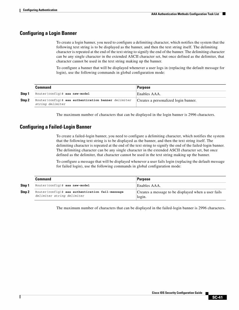
Configuring AuthenticationAAA Authentication Methods Configuration Task List
SC-41Cisco IOS Security Configuration Guide
Configuring a Login Banner
To create a login banner, you need to configure a delimiting character, which notifies the system that the following text string is to be displayed as the banner, and then the text string itself. The delimiting character is repeated at the end of the text string to signify the end of the banner. The delimiting character can be any single character in the extended ASCII character set, but once defined as the delimiter, that character cannot be used in the text string making up the banner.
To configure a banner that will be displayed whenever a user logs in (replacing the default message for login), use the following commands in global configuration mode:
The maximum number of characters that can be displayed in the login banner is 2996 characters.
Configuring a Failed-Login Banner
To create a failed-login banner, you need to configure a delimiting character, which notifies the system that the following text string is to be displayed as the banner, and then the text string itself. The delimiting character is repeated at the end of the text string to signify the end of the failed-login banner. The delimiting character can be any single character in the extended ASCII character set, but once defined as the delimiter, that character cannot be used in the text string making up the banner.
To configure a message that will be displayed whenever a user fails login (replacing the default message for failed login), use the following commands in global configuration mode:
The maximum number of characters that can be displayed in the failed-login banner is 2996 characters.
Command Purpose
Step 1 Router(config)# aaa new-model Enables AAA.
Step 2 Router(config)# aaa authentication banner delimiter string delimiter
Creates a personalized login banner.
Command Purpose
Step 1 Router(config)# aaa new-model Enables AAA.
Step 2 Router(config)# aaa authentication fail-message delimiter string delimiter
Creates a message to be displayed when a user fails login.
Configuring AuthenticationAAA Authentication Methods Configuration Task List
SC-42Cisco IOS Security Configuration Guide
Configuring AAA Packet of DisconnectPacket of disconnect (POD) terminates connections on the network access server (NAS) when particular session attributes are identified. By using session information obtained from AAA, the POD client residing on a UNIX workstation sends disconnect packets to the POD server running on the network access server. The NAS terminates any inbound user session with one or more matching key attributes. It rejects requests when required fields are missing or when an exact match is not found.
To configure POD, perform the following tasks in global configuration mode:
Enabling Double AuthenticationPreviously, PPP sessions could only be authenticated by using a single authentication method: either PAP or CHAP. Double authentication requires remote users to pass a second stage of authentication—after CHAP or PAP authentication—before gaining network access.
This second (“double”) authentication requires a password that is known to the user but not stored on the user’s remote host. Therefore, the second authentication is specific to a user, not to a host. This provides an additional level of security that will be effective even if information from the remote host is stolen. In addition, this also provides greater flexibility by allowing customized network privileges for each user.
The second stage authentication can use one-time passwords such as token card passwords, which are not supported by CHAP. If one-time passwords are used, a stolen user password is of no use to the perpetrator.
This section includes the following subsections:
• How Double Authentication Works
• Configuring Double Authentication
• Accessing the User Profile After Double Authentication
How Double Authentication Works
With double authentication, there are two authentication/authorization stages. These two stages occur after a remote user dials in and a PPP session is initiated.
In the first stage, the user logs in using the remote host name; CHAP (or PAP) authenticates the remote host, and then PPP negotiates with AAA to authorize the remote host. In this process, the network access privileges associated with the remote host are assigned to the user.
Command Purpose
Step 1 Router(config)# aaa accounting network default start-stop radius
Enables AAA accounting records.
Step 2 Router(config)# aaa accounting delay-start (Optional) Delays generation of the start accounting record until the Framed-IP-Address is assigned, allowing its use in the POD packet.
Step 3 Router(config)# aaa pod server server-key string Enables POD reception.
Step 4 Router(config)# radius-server host IP address non-standard
Declares a RADIUS host that uses a vendor-proprietary version of RADIUS.
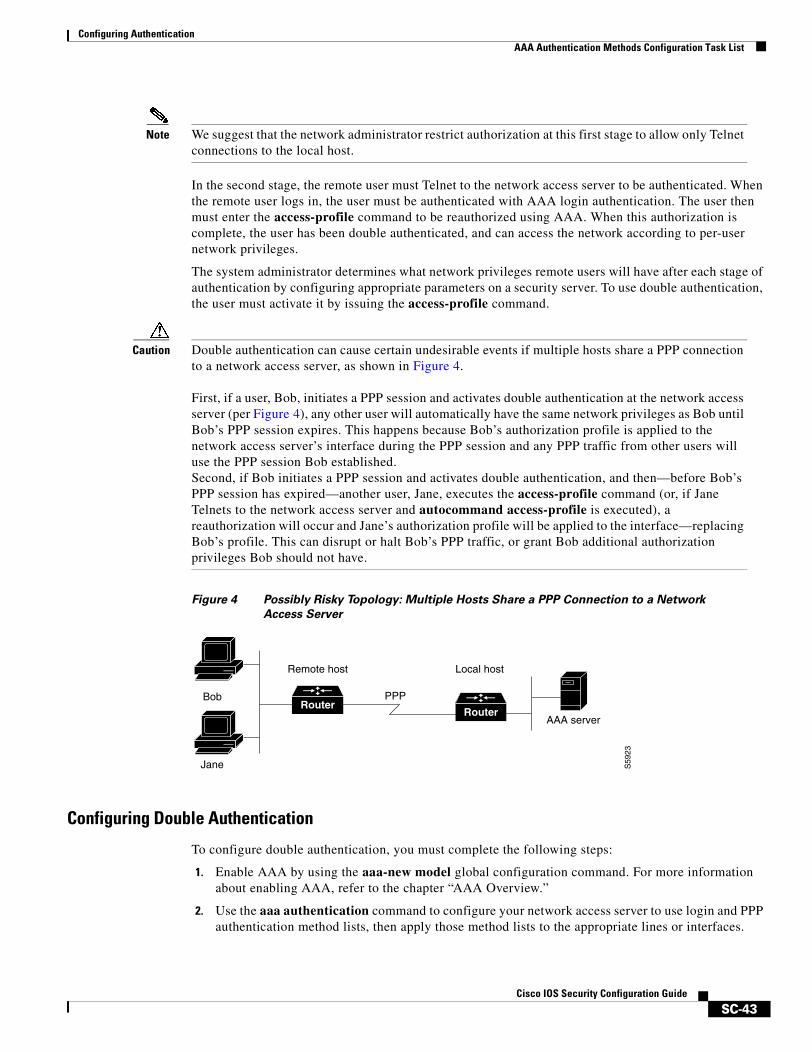
Configuring AuthenticationAAA Authentication Methods Configuration Task List
SC-43Cisco IOS Security Configuration Guide
Note We suggest that the network administrator restrict authorization at this first stage to allow only Telnet connections to the local host.
In the second stage, the remote user must Telnet to the network access server to be authenticated. When the remote user logs in, the user must be authenticated with AAA login authentication. The user then must enter the access-profile command to be reauthorized using AAA. When this authorization is complete, the user has been double authenticated, and can access the network according to per-user network privileges.
The system administrator determines what network privileges remote users will have after each stage of authentication by configuring appropriate parameters on a security server. To use double authentication, the user must activate it by issuing the access-profile command.
Caution Double authentication can cause certain undesirable events if multiple hosts share a PPP connection to a network access server, as shown in Figure 4.
First, if a user, Bob, initiates a PPP session and activates double authentication at the network access server (per Figure 4), any other user will automatically have the same network privileges as Bob until Bob’s PPP session expires. This happens because Bob’s authorization profile is applied to the network access server’s interface during the PPP session and any PPP traffic from other users will use the PPP session Bob established.Second, if Bob initiates a PPP session and activates double authentication, and then—before Bob’s PPP session has expired—another user, Jane, executes the access-profile command (or, if Jane Telnets to the network access server and autocommand access-profile is executed), a reauthorization will occur and Jane’s authorization profile will be applied to the interface—replacing Bob’s profile. This can disrupt or halt Bob’s PPP traffic, or grant Bob additional authorization privileges Bob should not have.
Figure 4 Possibly Risky Topology: Multiple Hosts Share a PPP Connection to a Network
Access Server
Configuring Double Authentication
To configure double authentication, you must complete the following steps:
1. Enable AAA by using the aaa-new model global configuration command. For more information about enabling AAA, refer to the chapter “AAA Overview.”
2. Use the aaa authentication command to configure your network access server to use login and PPP authentication method lists, then apply those method lists to the appropriate lines or interfaces.
Bob PPP
AAA server
Local host
S59
23
Remote host
RouterRouter
Jane
Configuring AuthenticationAAA Authentication Methods Configuration Task List
SC-44Cisco IOS Security Configuration Guide
3. Use the aaa authorization command to configure AAA network authorization at login. For more information about configuring network authorization, refer to the “Configuring Authorization” chapter.
4. Configure security protocol parameters (for example, RADIUS or TACACS+). For more information about RADIUS, refer to the chapter “Configuring RADIUS”. For more information about TACACS+, refer to the chapter “Configuring TACACS+.”
5. Use access control list AV pairs on the security server that the user can connect to the local host only by establishing a Telnet connection.
6. (Optional) Configure the access-profile command as an autocommand. If you configure the autocommand, remote users will not have to manually enter the access-profile command to access authorized rights associated with their personal user profile. To learn about configuring autocommands, refer to the autocommand command in the Cisco IOS Dial Technologies Command Reference: Network Services.
Note If the access-profile command is configured as an autocommand, users will still have to Telnet to the local host and log in to complete double authentication.
Follow these rules when creating the user-specific authorization statements (These rules relate to the default behavior of the access-profile command):
• Use valid AV pairs when configuring access control list AV pairs on the security server. For a list of valid AV pairs, refer to the chapter “Authentication Commands” in the Cisco IOS Security Command Reference.
• If you want remote users to use the interface’s existing authorization (that which existed prior to the second stage authentication/authorization), but you want them to have different access control lists (ACLs), you should specify only ACL AV pairs in the user-specific authorization definition. This might be desirable if you set up a default authorization profile to apply to the remote host, but want to apply specific ACLs to specific users.
• When these user-specific authorization statements are later applied to the interface, they can either be added to the existing interface configuration or they can replace the existing interface configuration—depending on which form of the access-profile command is used to authorize the user. You should understand how the access-profile command works before configuring the authorization statements.
• If you will be using ISDN or Multilink PPP, you must also configure virtual templates at the local host.
To troubleshoot double authentication, use the debug aaa per-user debug command. For more information about this command, refer to the Cisco IOS Debug Command Reference.
Accessing the User Profile After Double Authentication
In double authentication, when a remote user establishes a PPP link to the local host using the local host name, the remote host is CHAP (or PAP) authenticated. After CHAP (or PAP) authentication, PPP negotiates with AAA to assign network access privileges associated with the remote host to the user. (We suggest that privileges at this stage be restricted to allow the user to connect to the local host only by establishing a Telnet connection.)
When the user needs to initiate the second phase of double authentication, establishing a Telnet connection to the local host, the user enters a personal username and password (different from the CHAP or PAP username and password). This action causes AAA reauthentication to occur according to the
Configuring AuthenticationAAA Authentication Methods Configuration Task List
SC-45Cisco IOS Security Configuration Guide
personal username/password. The initial rights associated with the local host, though, are still in place. By using the access-profile command, the rights associated with the local host are replaced by or merged with those defined for the user in the user’s profile.
To access the user profile after double authentication, use the following command in EXEC configuration mode:
If you configured the access-profile command to be executed as an autocommand, it will be executed automatically after the remote user logs in.
Enabling Automated Double AuthenticationYou can make the double authentication process easier for users by implementing automated double authentication. Automated double authentication provides all of the security benefits of double authentication, but offers a simpler, more user-friendly interface for remote users. With double authentication, a second level of user authentication is achieved when the user Telnets to the network access server or router and enters a username and password. With automated double authentication, the user does not have to Telnet to the network access server; instead the user responds to a dialog box that requests a username and password or personal identification number (PIN). To use the automated double authentication feature, the remote user hosts must be running a companion client application. As of Cisco IOS Release 12.0, the only client application software available is the Glacier Bay application server software for PCs.
Note Automated double authentication, like the existing double authentication feature, is for Multilink PPP ISDN connections only. Automated double authentication cannot be used with other protocols such as X.25 or SLIP.
Automated double authentication is an enhancement to the existing double authentication feature. To configure automated double authentication, you must first configure double authentication by completing the following steps:
1. Enable AAA by using the aaa-new model global configuration command. For more information about enabling AAA, refer to the chapter “AAA Overview.”
2. Use the aaa authentication command to configure your network access server to use login and PPP authentication method lists, then apply those method lists to the appropriate lines or interfaces.
3. Use the aaa authorization command to configure AAA network authorization at login. For more information about configuring network authorization, refer to the chapter “Configuring Authorization.”
4. Configure security protocol parameters (for example, RADIUS or TACACS+). For more information about RADIUS, refer to the chapter “Configuring RADIUS”. For more information about TACACS+, refer to the chapter “Configuring TACACS+.”
Command Purpose
Router> access-profile [merge | replace] [ignore-sanity-checks]
Accesses the rights associated for the user after double authentication.
Configuring AuthenticationAAA Authentication Methods Configuration Task List
SC-46Cisco IOS Security Configuration Guide
5. Use access control list AV pairs on the security server that the user can connect to the local host only by establishing a Telnet connection.
6. Configure the access-profile command as an autocommand. If you configure the autocommand, remote users will not have to manually enter the access-profile command to access authorized rights associated with their personal user profile. To learn about configuring autocommands, refer to the autocommand command in the Cisco IOS Dial Technologies Command Reference, Release 12.2.
Note If the access-profile command is configured as an autocommand, users will still have to Telnet to the local host and log in to complete double authentication.
Follow these rules when creating the user-specific authorization statements (These rules relate to the default behavior of the access-profile command):
• Use valid AV pairs when configuring access control list AV pairs on the security server. For a list of valid AV pairs, refer to the chapter “Authentication Commands” in the Cisco IOS Security Command Reference.
• If you want remote users to use the interface’s existing authorization (that which existed prior to the second stage authentication/authorization), but you want them to have different access control lists (ACLs), you should specify only ACL AV pairs in the user-specific authorization definition. This might be desirable if you set up a default authorization profile to apply to the remote host, but want to apply specific ACLs to specific users.
• When these user-specific authorization statements are later applied to the interface, they can either be added to the existing interface configuration, or replace the existing interface configuration—depending on which form of the access-profile command is used to authorize the user. You should understand how the access-profile command works before configuring the authorization statements.
• If you will be using ISDN or Multilink PPP, you must also configure virtual templates at the local host.
To troubleshoot double authentication, use the debug aaa per-user debug command. For more information about this command, refer to the Cisco IOS Debug Command Reference.
After you have configured double authentication, you are ready to configure the automation enhancement.
To configure automated double authentication, use the following commands, starting in global configuration mode.
:
Command Purpose
Step 1 Router(config)# ip trigger-authentication [timeout seconds] [port number]
Enables automation of double authentication.
Step 2 Router(config)# interface bri number
or
Router(config)# interface serial number:23
Selects an ISDN BRI or ISDN PRI interface and enter the interface configuration mode.
Step 3 Router(config-if)# ip trigger-authentication Applies automated double authentication to the interface.
Configuring AuthenticationNon-AAA Authentication Methods
SC-47Cisco IOS Security Configuration Guide
To troubleshoot automated double authentication, use the following commands in privileged EXEC mode:
Non-AAA Authentication MethodsThis section discusses the following non-AAA authentication tasks:
• Configuring Line Password Protection
• Establishing Username Authentication
• Enabling CHAP or PAP Authentication
• Using MS-CHAP
Configuring Line Password ProtectionYou can provide access control on a terminal line by entering the password and establishing password checking. To do so, use the following commands in line configuration mode:
The password checker is case sensitive and can include spaces; for example, the password “Secret” is different from the password “secret,” and “two words” is an acceptable password.
You can disable line password verification by disabling password checking. To do so, use the following command in line configuration mode:
Command Purpose
Step 1 Router# show ip trigger-authentication Displays the list of remote hosts for which automated double authentication has been attempted (successfully or unsuccessfully).
Step 2 Router# clear ip trigger-authentication Clears the list of remote hosts for which automated double authentication has been attempted. (This clears the table displayed by the show ip trigger-authentication command.)
Step 3 Router# debug ip trigger-authentication Displays debug output related to automated double authentication.
Command Purpose
Step 1 Router(config-line)# password password Assigns a password to a terminal or other device on a line.
Step 2 Router(config-line)# login Enables password checking at login.
Command PurposeRouter(config-line)# no login Disables password checking or allow access to a line without password
verification.
Configuring AuthenticationNon-AAA Authentication Methods
SC-48Cisco IOS Security Configuration Guide
If you configure line password protection and then configure TACACS or extended TACACS, the TACACS username and password take precedence over line passwords. If you have not yet implemented a security policy, we recommend that you use AAA.
Note The login command only changes username and privilege level but it does not execute a shell; therefore autocommands will not be executed. To execute autocommands under this circumstance, you need to establish a Telnet session back into the router (loop-back). Make sure that the router has been configured for secure Telnet sessions if you choose to implement autocommands this way.
Establishing Username AuthenticationYou can create a username-based authentication system, which is useful in the following situations:
• To provide a TACACS-like username and encrypted password-authentication system for networks that cannot support TACACS
• To provide special-case logins: for example, access list verification, no password verification, autocommand execution at login, and “no escape” situations
To establish username authentication, use the following commands in global configuration mode as needed for your system configuration:
The keyword noescape prevents users from using escape characters on the hosts to which they are connected. The nohangup feature does not disconnect after using the autocommand.
Caution Passwords will be displayed in clear text in your configuration unless you enable the service password-encryption command. For more information about the service password-encryption command, refer to the chapter “Passwords and Privileges Commands” in the Cisco IOS Security Command Reference.
Command Purpose
Step 1 Router(config)# username name [nopassword | password password | password encryption-type encrypted password]
or
Router(config)# username name [access-class number]
Establishes username authentication with encrypted passwords.
or
(Optional) Establishes username authentication by access list.
Step 2 Router(config)# username name [privilege level] (Optional) Sets the privilege level for the user.
Step 3 Router(config)# username name [autocommand command] (Optional) Specifies a command to be executed automatically.
Step 4 Router(config)# username name [noescape] [nohangup] (Optional) Sets a “no escape” login environment.
Configuring AuthenticationNon-AAA Authentication Methods
SC-49Cisco IOS Security Configuration Guide
Enabling CHAP or PAP AuthenticationOne of the most common transport protocols used in Internet service providers’ (ISPs’) dial solutions is the Point-to-Point Protocol (PPP). Traditionally, remote users dial in to an access server to initiate a PPP session. After PPP has been negotiated, remote users are connected to the ISP network and to the Internet.
Because ISPs want only customers to connect to their access servers, remote users are required to authenticate to the access server before they can start up a PPP session. Normally, a remote user authenticates by typing in a username and password when prompted by the access server. Although this is a workable solution, it is difficult to administer and awkward for the remote user.
A better solution is to use the authentication protocols built into PPP. In this case, the remote user dials in to the access server and starts up a minimal subset of PPP with the access server. This does not give the remote user access to the ISP’s network—it merely allows the access server to talk to the remote device.
PPP currently supports two authentication protocols: Password Authentication Protocol (PAP) and Challenge Handshake Authentication Protocol (CHAP). Both are specified in RFC 1334 and are supported on synchronous and asynchronous interfaces. Authentication via PAP or CHAP is equivalent to typing in a username and password when prompted by the server. CHAP is considered to be more secure because the remote user’s password is never sent across the connection.
PPP (with or without PAP or CHAP authentication) is also supported in dialout solutions. An access server utilizes a dialout feature when it initiates a call to a remote device and attempts to start up a transport protocol such as PPP.
See the chapter “Configuring Interfaces” in the Cisco IOS Configuration Fundamentals Configuration Guide for more information about CHAP and PAP.
Note To use CHAP or PAP, you must be running PPP encapsulation.
When CHAP is enabled on an interface and a remote device attempts to connect to it, the access server sends a CHAP packet to the remote device. The CHAP packet requests or “challenges” the remote device to respond. The challenge packet consists of an ID, a random number, and the host name of the local router.
When the remote device receives the challenge packet, it concatenates the ID, the remote device’s password, and the random number, and then encrypts all of it using the remote device’s password. The remote device sends the results back to the access server, along with the name associated with the password used in the encryption process.
When the access server receives the response, it uses the name it received to retrieve a password stored in its user database. The retrieved password should be the same password the remote device used in its encryption process. The access server then encrypts the concatenated information with the newly retrieved password—if the result matches the result sent in the response packet, authentication succeeds.
The benefit of using CHAP authentication is that the remote device’s password is never transmitted in clear text. This prevents other devices from stealing it and gaining illegal access to the ISP’s network.
CHAP transactions occur only at the time a link is established. The access server does not request a password during the rest of the call. (The local device can, however, respond to such requests from other devices during a call.)
When PAP is enabled, the remote router attempting to connect to the access server is required to send an authentication request. If the username and password specified in the authentication request are accepted, the Cisco IOS software sends an authentication acknowledgment.
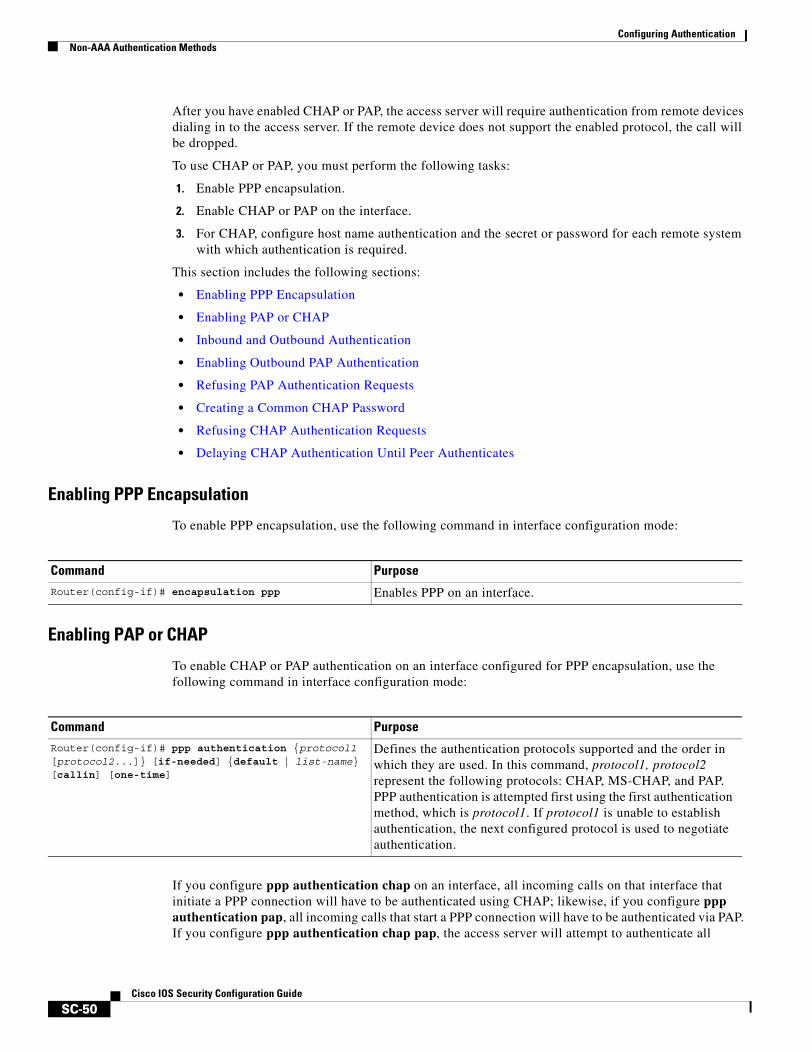
Configuring AuthenticationNon-AAA Authentication Methods
SC-50Cisco IOS Security Configuration Guide
After you have enabled CHAP or PAP, the access server will require authentication from remote devices dialing in to the access server. If the remote device does not support the enabled protocol, the call will be dropped.
To use CHAP or PAP, you must perform the following tasks:
1. Enable PPP encapsulation.
2. Enable CHAP or PAP on the interface.
3. For CHAP, configure host name authentication and the secret or password for each remote system with which authentication is required.
This section includes the following sections:
• Enabling PPP Encapsulation
• Enabling PAP or CHAP
• Inbound and Outbound Authentication
• Enabling Outbound PAP Authentication
• Refusing PAP Authentication Requests
• Creating a Common CHAP Password
• Refusing CHAP Authentication Requests
• Delaying CHAP Authentication Until Peer Authenticates
Enabling PPP Encapsulation
To enable PPP encapsulation, use the following command in interface configuration mode:
Enabling PAP or CHAP
To enable CHAP or PAP authentication on an interface configured for PPP encapsulation, use the following command in interface configuration mode:
If you configure ppp authentication chap on an interface, all incoming calls on that interface that initiate a PPP connection will have to be authenticated using CHAP; likewise, if you configure ppp authentication pap, all incoming calls that start a PPP connection will have to be authenticated via PAP. If you configure ppp authentication chap pap, the access server will attempt to authenticate all
Command PurposeRouter(config-if)# encapsulation ppp Enables PPP on an interface.
Command PurposeRouter(config-if)# ppp authentication {protocol1 [protocol2...]} [if-needed] {default | list-name} [callin] [one-time]
Defines the authentication protocols supported and the order in which they are used. In this command, protocol1, protocol2 represent the following protocols: CHAP, MS-CHAP, and PAP. PPP authentication is attempted first using the first authentication method, which is protocol1. If protocol1 is unable to establish authentication, the next configured protocol is used to negotiate authentication.
Configuring AuthenticationNon-AAA Authentication Methods
SC-51Cisco IOS Security Configuration Guide
incoming calls that start a PPP session with CHAP. If the remote device does not support CHAP, the access server will try to authenticate the call using PAP. If the remote device does not support either CHAP or PAP, authentication will fail and the call will be dropped. If you configure ppp authentication pap chap, the access server will attempt to authenticate all incoming calls that start a PPP session with PAP. If the remote device does not support PAP, the access server will try to authenticate the call using CHAP. If the remote device does not support either protocol, authentication will fail and the call will be dropped. If you configure the ppp authentication command with the callin keyword, the access server will only authenticate the remote device if the remote device initiated the call.
Authentication method lists and the one-time keyword are only available if you have enabled AAA—they will not be available if you are using TACACS or extended TACACS. If you specify the name of an authentication method list with the ppp authentication command, PPP will attempt to authenticate the connection using the methods defined in the specified method list. If AAA is enabled and no method list is defined by name, PPP will attempt to authenticate the connection using the methods defined as the default. The ppp authentication command with the one-time keyword enables support for one-time passwords during authentication.
The if-needed keyword is only available if you are using TACACS or extended TACACS. The ppp authentication command with the if-needed keyword means that PPP will only authenticate the remote device via PAP or CHAP if they have not yet authenticated during the life of the current call. If the remote device authenticated via a standard login procedure and initiated PPP from the EXEC prompt, PPP will not authenticate via CHAP if ppp authentication chap if-needed is configured on the interface.
Caution If you use a list-name that has not been configured with the aaa authentication ppp command, you disable PPP on the line.
For information about adding a username entry for each remote system from which the local router or access server requires authentication, see the section “Establishing Username Authentication.”
Inbound and Outbound Authentication
PPP supports two-way authentication. Normally, when a remote device dials in to an access server, the access server requests that the remote device prove that it is allowed access. This is known as inbound authentication. At the same time, the remote device can also request that the access server prove that it is who it says it is. This is known as outbound authentication. An access server also does outbound authentication when it initiates a call to a remote device.
Enabling Outbound PAP Authentication
To enable outbound PAP authentication, use the following command in interface configuration mode:
The access server uses the username and password specified by the ppp pap sent-username command to authenticate itself whenever it initiates a call to a remote device or when it has to respond to a remote device’s request for outbound authentication.
Command PurposeRouter(config-if)# ppp pap sent-username username password password Enables outbound PAP authentication.
Configuring AuthenticationNon-AAA Authentication Methods
SC-52Cisco IOS Security Configuration Guide
Refusing PAP Authentication Requests
To refuse PAP authentication from peers requesting it, meaning that PAP authentication is disabled for all calls, use the following command in interface configuration mode:
If the refuse keyword is not used, the router will not refuse any PAP authentication challenges received from the peer.
Creating a Common CHAP Password
For remote CHAP authentication only, you can configure your router to create a common CHAP secret password to use in response to challenges from an unknown peer; for example, if your router calls a rotary of routers (either from another vendor, or running an older version of the Cisco IOS software) to which a new (that is, unknown) router has been added. The ppp chap password command allows you to replace several username and password configuration commands with a single copy of this command on any dialer interface or asynchronous group interface.
To enable a router calling a collection of routers to configure a common CHAP secret password, use the following command in interface configuration mode:
Refusing CHAP Authentication Requests
To refuse CHAP authentication from peers requesting it, meaning that CHAP authentication is disabled for all calls, use the following command in interface configuration mode:
If the callin keyword is used, the router will refuse to answer CHAP authentication challenges received from the peer, but will still require the peer to answer any CHAP challenges the router sends.
If outbound PAP has been enabled (using the ppp pap sent-username command), PAP will be suggested as the authentication method in the refusal packet.
Command PurposeRouter(config-if)# ppp pap refuse Refuses PAP authentication from peers
requesting PAP authentication.
Command PurposeRouter(config-if)# ppp chap password secret Enables a router calling a collection of routers to configure a
common CHAP secret password.
Command PurposeRouter(config-if)# ppp chap refuse [callin] Refuses CHAP authentication from peers requesting CHAP
authentication.
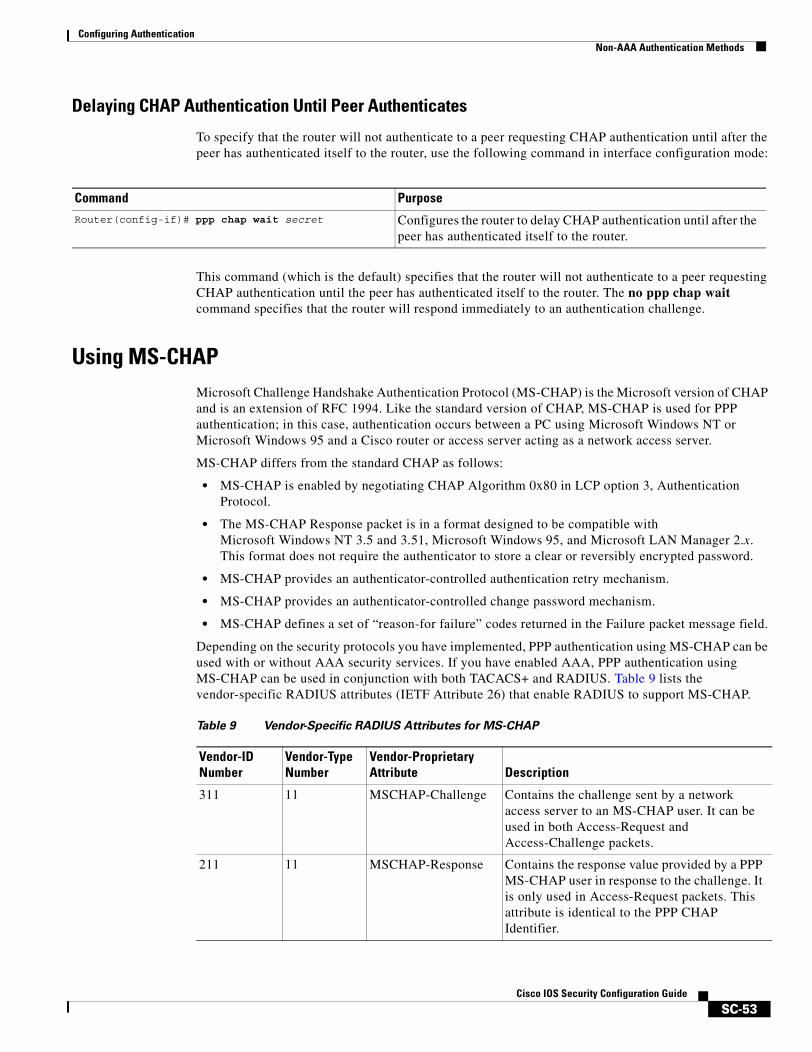
Configuring AuthenticationNon-AAA Authentication Methods
SC-53Cisco IOS Security Configuration Guide
Delaying CHAP Authentication Until Peer Authenticates
To specify that the router will not authenticate to a peer requesting CHAP authentication until after the peer has authenticated itself to the router, use the following command in interface configuration mode:
This command (which is the default) specifies that the router will not authenticate to a peer requesting CHAP authentication until the peer has authenticated itself to the router. The no ppp chap wait command specifies that the router will respond immediately to an authentication challenge.
Using MS-CHAPMicrosoft Challenge Handshake Authentication Protocol (MS-CHAP) is the Microsoft version of CHAP and is an extension of RFC 1994. Like the standard version of CHAP, MS-CHAP is used for PPP authentication; in this case, authentication occurs between a PC using Microsoft Windows NT or Microsoft Windows 95 and a Cisco router or access server acting as a network access server.
MS-CHAP differs from the standard CHAP as follows:
• MS-CHAP is enabled by negotiating CHAP Algorithm 0x80 in LCP option 3, Authentication Protocol.
• The MS-CHAP Response packet is in a format designed to be compatible with Microsoft Windows NT 3.5 and 3.51, Microsoft Windows 95, and Microsoft LAN Manager 2.x. This format does not require the authenticator to store a clear or reversibly encrypted password.
• MS-CHAP provides an authenticator-controlled authentication retry mechanism.
• MS-CHAP provides an authenticator-controlled change password mechanism.
• MS-CHAP defines a set of “reason-for failure” codes returned in the Failure packet message field.
Depending on the security protocols you have implemented, PPP authentication using MS-CHAP can be used with or without AAA security services. If you have enabled AAA, PPP authentication using MS-CHAP can be used in conjunction with both TACACS+ and RADIUS. Table 9 lists the vendor-specific RADIUS attributes (IETF Attribute 26) that enable RADIUS to support MS-CHAP.
Command Purpose
Router(config-if)# ppp chap wait secret Configures the router to delay CHAP authentication until after the peer has authenticated itself to the router.
Table 9 Vendor-Specific RADIUS Attributes for MS-CHAP
Vendor-IDNumber
Vendor-TypeNumber
Vendor-Proprietary Attribute Description
311 11 MSCHAP-Challenge Contains the challenge sent by a network access server to an MS-CHAP user. It can be used in both Access-Request and Access-Challenge packets.
211 11 MSCHAP-Response Contains the response value provided by a PPP MS-CHAP user in response to the challenge. It is only used in Access-Request packets. This attribute is identical to the PPP CHAP Identifier.
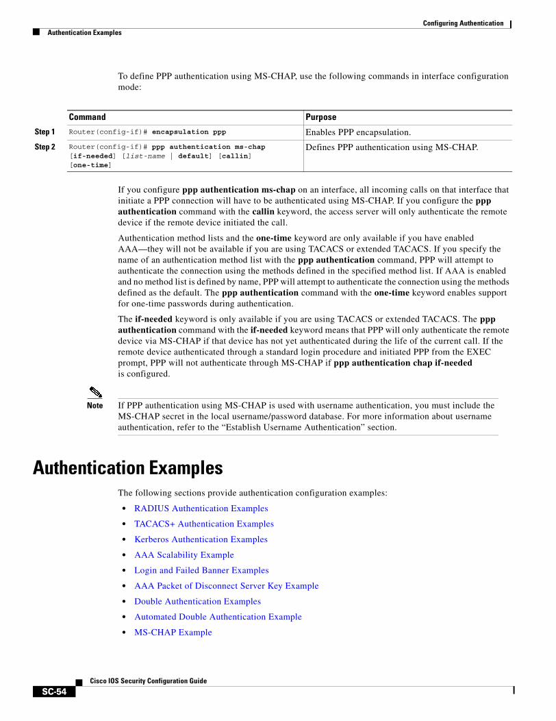
Configuring AuthenticationAuthentication Examples
SC-54Cisco IOS Security Configuration Guide
To define PPP authentication using MS-CHAP, use the following commands in interface configuration mode:
If you configure ppp authentication ms-chap on an interface, all incoming calls on that interface that initiate a PPP connection will have to be authenticated using MS-CHAP. If you configure the ppp authentication command with the callin keyword, the access server will only authenticate the remote device if the remote device initiated the call.
Authentication method lists and the one-time keyword are only available if you have enabled AAA—they will not be available if you are using TACACS or extended TACACS. If you specify the name of an authentication method list with the ppp authentication command, PPP will attempt to authenticate the connection using the methods defined in the specified method list. If AAA is enabled and no method list is defined by name, PPP will attempt to authenticate the connection using the methods defined as the default. The ppp authentication command with the one-time keyword enables support for one-time passwords during authentication.
The if-needed keyword is only available if you are using TACACS or extended TACACS. The ppp authentication command with the if-needed keyword means that PPP will only authenticate the remote device via MS-CHAP if that device has not yet authenticated during the life of the current call. If the remote device authenticated through a standard login procedure and initiated PPP from the EXEC prompt, PPP will not authenticate through MS-CHAP if ppp authentication chap if-needed is configured.
Note If PPP authentication using MS-CHAP is used with username authentication, you must include the MS-CHAP secret in the local username/password database. For more information about username authentication, refer to the “Establish Username Authentication” section.
Authentication ExamplesThe following sections provide authentication configuration examples:
• RADIUS Authentication Examples
• TACACS+ Authentication Examples
• Kerberos Authentication Examples
• AAA Scalability Example
• Login and Failed Banner Examples
• AAA Packet of Disconnect Server Key Example
• Double Authentication Examples
• Automated Double Authentication Example
• MS-CHAP Example
Command Purpose
Step 1 Router(config-if)# encapsulation ppp Enables PPP encapsulation.
Step 2 Router(config-if)# ppp authentication ms-chap [if-needed] [list-name | default] [callin] [one-time]
Defines PPP authentication using MS-CHAP.
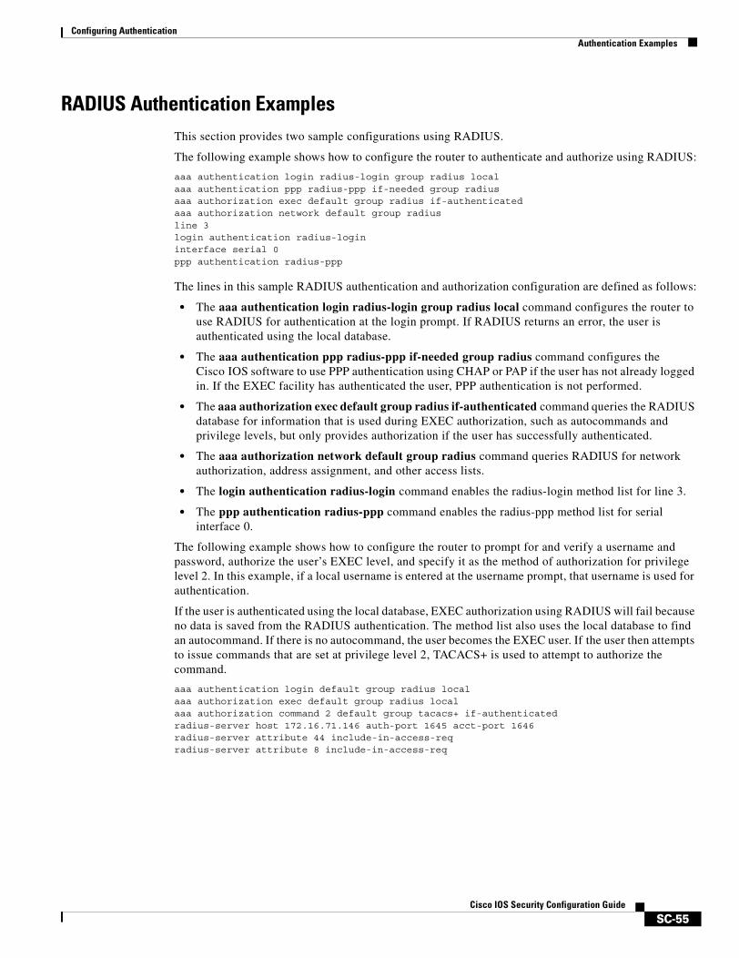
Configuring AuthenticationAuthentication Examples
SC-55Cisco IOS Security Configuration Guide
RADIUS Authentication ExamplesThis section provides two sample configurations using RADIUS.
The following example shows how to configure the router to authenticate and authorize using RADIUS:
aaa authentication login radius-login group radius localaaa authentication ppp radius-ppp if-needed group radiusaaa authorization exec default group radius if-authenticatedaaa authorization network default group radiusline 3login authentication radius-logininterface serial 0ppp authentication radius-ppp
The lines in this sample RADIUS authentication and authorization configuration are defined as follows:
• The aaa authentication login radius-login group radius local command configures the router to use RADIUS for authentication at the login prompt. If RADIUS returns an error, the user is authenticated using the local database.
• The aaa authentication ppp radius-ppp if-needed group radius command configures the Cisco IOS software to use PPP authentication using CHAP or PAP if the user has not already logged in. If the EXEC facility has authenticated the user, PPP authentication is not performed.
• The aaa authorization exec default group radius if-authenticated command queries the RADIUS database for information that is used during EXEC authorization, such as autocommands and privilege levels, but only provides authorization if the user has successfully authenticated.
• The aaa authorization network default group radius command queries RADIUS for network authorization, address assignment, and other access lists.
• The login authentication radius-login command enables the radius-login method list for line 3.
• The ppp authentication radius-ppp command enables the radius-ppp method list for serial interface 0.
The following example shows how to configure the router to prompt for and verify a username and password, authorize the user’s EXEC level, and specify it as the method of authorization for privilege level 2. In this example, if a local username is entered at the username prompt, that username is used for authentication.
If the user is authenticated using the local database, EXEC authorization using RADIUS will fail because no data is saved from the RADIUS authentication. The method list also uses the local database to find an autocommand. If there is no autocommand, the user becomes the EXEC user. If the user then attempts to issue commands that are set at privilege level 2, TACACS+ is used to attempt to authorize the command.
aaa authentication login default group radius localaaa authorization exec default group radius localaaa authorization command 2 default group tacacs+ if-authenticated radius-server host 172.16.71.146 auth-port 1645 acct-port 1646radius-server attribute 44 include-in-access-reqradius-server attribute 8 include-in-access-req
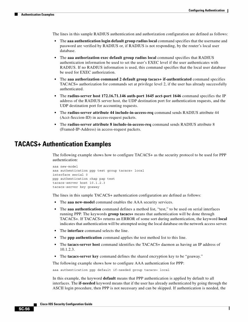
Configuring AuthenticationAuthentication Examples
SC-56Cisco IOS Security Configuration Guide
The lines in this sample RADIUS authentication and authorization configuration are defined as follows:
• The aaa authentication login default group radius local command specifies that the username and password are verified by RADIUS or, if RADIUS is not responding, by the router’s local user database.
• The aaa authorization exec default group radius local command specifies that RADIUS authentication information be used to set the user’s EXEC level if the user authenticates with RADIUS. If no RADIUS information is used, this command specifies that the local user database be used for EXEC authorization.
• The aaa authorization command 2 default group tacacs+ if-authenticated command specifies TACACS+ authorization for commands set at privilege level 2, if the user has already successfully authenticated.
• The radius-server host 172.16.71.146 auth-port 1645 acct-port 1646 command specifies the IP address of the RADIUS server host, the UDP destination port for authentication requests, and the UDP destination port for accounting requests.
• The radius-server attribute 44 include-in-access-req command sends RADIUS attribute 44 (Acct-Seccion-ID) in access-request packets.
• The radius-server attribute 8 include-in-access-req command sends RADIUS attribute 8 (Framed-IP-Address) in access-request packets.
TACACS+ Authentication ExamplesThe following example shows how to configure TACACS+ as the security protocol to be used for PPP authentication:
aaa new-modelaaa authentication ppp test group tacacs+ localinterface serial 0ppp authentication chap pap testtacacs-server host 10.1.2.3tacacs-server key goaway
The lines in this sample TACACS+ authentication configuration are defined as follows:
• The aaa new-model command enables the AAA security services.
• The aaa authentication command defines a method list, “test,” to be used on serial interfaces running PPP. The keywords group tacacs+ means that authentication will be done through TACACS+. If TACACS+ returns an ERROR of some sort during authentication, the keyword local indicates that authentication will be attempted using the local database on the network access server.
• The interface command selects the line.
• The ppp authentication command applies the test method list to this line.
• The tacacs-server host command identifies the TACACS+ daemon as having an IP address of 10.1.2.3.
• The tacacs-server key command defines the shared encryption key to be “goaway.”
The following example shows how to configure AAA authentication for PPP:
aaa authentication ppp default if-needed group tacacs+ local
In this example, the keyword default means that PPP authentication is applied by default to all interfaces. The if-needed keyword means that if the user has already authenticated by going through the ASCII login procedure, then PPP is not necessary and can be skipped. If authentication is needed, the
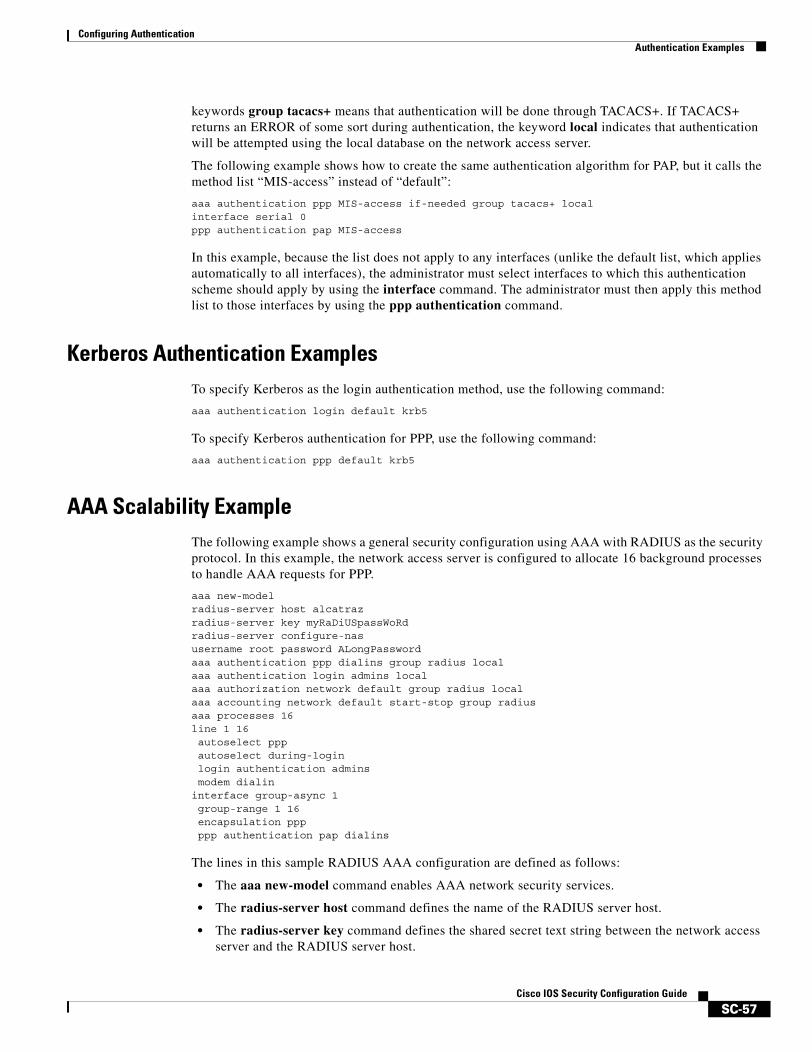
Configuring AuthenticationAuthentication Examples
SC-57Cisco IOS Security Configuration Guide
keywords group tacacs+ means that authentication will be done through TACACS+. If TACACS+ returns an ERROR of some sort during authentication, the keyword local indicates that authentication will be attempted using the local database on the network access server.
The following example shows how to create the same authentication algorithm for PAP, but it calls the method list “MIS-access” instead of “default”:
aaa authentication ppp MIS-access if-needed group tacacs+ localinterface serial 0ppp authentication pap MIS-access
In this example, because the list does not apply to any interfaces (unlike the default list, which applies automatically to all interfaces), the administrator must select interfaces to which this authentication scheme should apply by using the interface command. The administrator must then apply this method list to those interfaces by using the ppp authentication command.
Kerberos Authentication ExamplesTo specify Kerberos as the login authentication method, use the following command:
aaa authentication login default krb5
To specify Kerberos authentication for PPP, use the following command:
aaa authentication ppp default krb5
AAA Scalability ExampleThe following example shows a general security configuration using AAA with RADIUS as the security protocol. In this example, the network access server is configured to allocate 16 background processes to handle AAA requests for PPP.
aaa new-modelradius-server host alcatrazradius-server key myRaDiUSpassWoRdradius-server configure-nasusername root password ALongPasswordaaa authentication ppp dialins group radius localaaa authentication login admins localaaa authorization network default group radius localaaa accounting network default start-stop group radiusaaa processes 16line 1 16autoselect pppautoselect during-loginlogin authentication adminsmodem dialin
interface group-async 1group-range 1 16encapsulation pppppp authentication pap dialins
The lines in this sample RADIUS AAA configuration are defined as follows:
• The aaa new-model command enables AAA network security services.
• The radius-server host command defines the name of the RADIUS server host.
• The radius-server key command defines the shared secret text string between the network access server and the RADIUS server host.
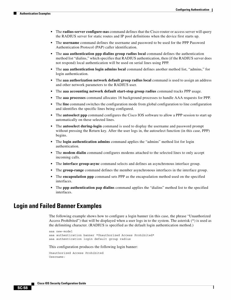
Configuring AuthenticationAuthentication Examples
SC-58Cisco IOS Security Configuration Guide
• The radius-server configure-nas command defines that the Cisco router or access server will query the RADIUS server for static routes and IP pool definitions when the device first starts up.
• The username command defines the username and password to be used for the PPP Password Authentication Protocol (PAP) caller identification.
• The aaa authentication ppp dialins group radius local command defines the authentication method list “dialins,” which specifies that RADIUS authentication, then (if the RADIUS server does not respond) local authentication will be used on serial lines using PPP.
• The aaa authentication login admins local command defines another method list, “admins,” for login authentication.
• The aaa authorization network default group radius local command is used to assign an address and other network parameters to the RADIUS user.
• The aaa accounting network default start-stop group radius command tracks PPP usage.
• The aaa processes command allocates 16 background processes to handle AAA requests for PPP.
• The line command switches the configuration mode from global configuration to line configuration and identifies the specific lines being configured.
• The autoselect ppp command configures the Cisco IOS software to allow a PPP session to start up automatically on these selected lines.
• The autoselect during-login command is used to display the username and password prompt without pressing the Return key. After the user logs in, the autoselect function (in this case, PPP) begins.
• The login authentication admins command applies the “admins” method list for login authentication.
• The modem dialin command configures modems attached to the selected lines to only accept incoming calls.
• The interface group-async command selects and defines an asynchronous interface group.
• The group-range command defines the member asynchronous interfaces in the interface group.
• The encapsulation ppp command sets PPP as the encapsulation method used on the specified interfaces.
• The ppp authentication pap dialins command applies the “dialins” method list to the specified interfaces.
Login and Failed Banner ExamplesThe following example shows how to configure a login banner (in this case, the phrase “Unauthorized Access Prohibited”) that will be displayed when a user logs in to the system. The asterisk (*) is used as the delimiting character. (RADIUS is specified as the default login authentication method.)
aaa new-modelaaa authentication banner *Unauthorized Access Prohibited*aaa authentication login default group radius
This configuration produces the following login banner:
Unauthorized Access ProhibitedUsername:

Configuring AuthenticationAuthentication Examples
SC-59Cisco IOS Security Configuration Guide
The following example shows how to additionally configure a failed login banner (in this case, the phrase “Failed login. Try again.”) that will be displayed when a user tries to log in to the system and fails. The asterisk (*) is used as the delimiting character. (RADIUS is specified as the default login authentication method.)
aaa new-modelaaa authentication banner *Unauthorized Access Prohibited*aaa authentication fail-message *Failed login. Try again.*aaa authentication login default group radius
This configuration produces the following login and failed login banner:
Unauthorized Access ProhibitedUsername: Password: Failed login. Try again.
AAA Packet of Disconnect Server Key ExampleThe following example shows how to configure POD (packet of disconnect), which terminates connections on the network access server (NAS) when particular session attributes are identified.
aaa new-modelaaa authentication ppp default radiusaaa accounting network default start-stop radiusaaa accounting delay-startaaa pod server server-key xyz123radius-server host 172.16.0.0 non-standardradius-server key rad123
Double Authentication ExamplesThe examples in this section illustrate possible configurations to be used with double authentication. Your configurations could differ significantly, depending on your network and security requirements.
This section includes the following examples:
• Configuration of the Local Host for AAA with Double Authentication Examples
• Configuration of the AAA Server for First-Stage (PPP) Authentication and Authorization Example
• Configuration of the AAA Server for Second-Stage (Per-User) Authentication and Authorization Examples
• Complete Configuration with TACACS+ Example
Note These configuration examples include specific IP addresses and other specific information. This information is for illustration purposes only: your configuration will use different IP addresses, different usernames and passwords, and different authorization statements.
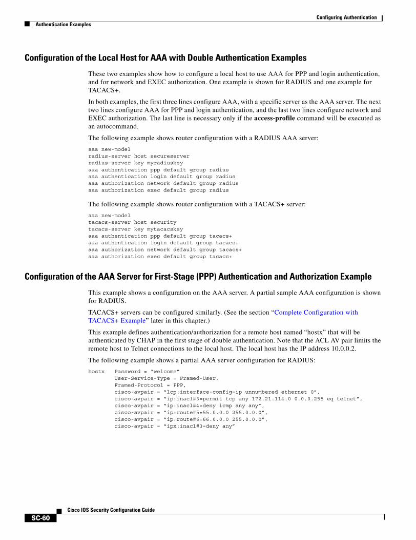
Configuring AuthenticationAuthentication Examples
SC-60Cisco IOS Security Configuration Guide
Configuration of the Local Host for AAA with Double Authentication Examples
These two examples show how to configure a local host to use AAA for PPP and login authentication, and for network and EXEC authorization. One example is shown for RADIUS and one example for TACACS+.
In both examples, the first three lines configure AAA, with a specific server as the AAA server. The next two lines configure AAA for PPP and login authentication, and the last two lines configure network and EXEC authorization. The last line is necessary only if the access-profile command will be executed as an autocommand.
The following example shows router configuration with a RADIUS AAA server:
aaa new-modelradius-server host secureserverradius-server key myradiuskeyaaa authentication ppp default group radiusaaa authentication login default group radiusaaa authorization network default group radiusaaa authorization exec default group radius
The following example shows router configuration with a TACACS+ server:
aaa new-modeltacacs-server host securitytacacs-server key mytacacskeyaaa authentication ppp default group tacacs+aaa authentication login default group tacacs+aaa authorization network default group tacacs+aaa authorization exec default group tacacs+
Configuration of the AAA Server for First-Stage (PPP) Authentication and Authorization Example
This example shows a configuration on the AAA server. A partial sample AAA configuration is shown for RADIUS.
TACACS+ servers can be configured similarly. (See the section “Complete Configuration with TACACS+ Example” later in this chapter.)
This example defines authentication/authorization for a remote host named “hostx” that will be authenticated by CHAP in the first stage of double authentication. Note that the ACL AV pair limits the remote host to Telnet connections to the local host. The local host has the IP address 10.0.0.2.
The following example shows a partial AAA server configuration for RADIUS:
hostx Password = “welcome”User-Service-Type = Framed-User,Framed-Protocol = PPP,cisco-avpair = “lcp:interface-config=ip unnumbered ethernet 0”,cisco-avpair = “ip:inacl#3=permit tcp any 172.21.114.0 0.0.0.255 eq telnet”,cisco-avpair = “ip:inacl#4=deny icmp any any”,cisco-avpair = “ip:route#5=55.0.0.0 255.0.0.0”,cisco-avpair = “ip:route#6=66.0.0.0 255.0.0.0”,cisco-avpair = “ipx:inacl#3=deny any”
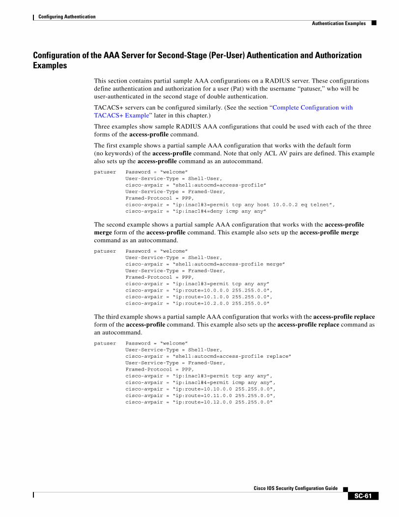
Configuring AuthenticationAuthentication Examples
SC-61Cisco IOS Security Configuration Guide
Configuration of the AAA Server for Second-Stage (Per-User) Authentication and Authorization Examples
This section contains partial sample AAA configurations on a RADIUS server. These configurations define authentication and authorization for a user (Pat) with the username “patuser,” who will be user-authenticated in the second stage of double authentication.
TACACS+ servers can be configured similarly. (See the section “Complete Configuration with TACACS+ Example” later in this chapter.)
Three examples show sample RADIUS AAA configurations that could be used with each of the three forms of the access-profile command.
The first example shows a partial sample AAA configuration that works with the default form (no keywords) of the access-profile command. Note that only ACL AV pairs are defined. This example also sets up the access-profile command as an autocommand.
patuser Password = “welcome”User-Service-Type = Shell-User,cisco-avpair = “shell:autocmd=access-profile”User-Service-Type = Framed-User,Framed-Protocol = PPP,cisco-avpair = “ip:inacl#3=permit tcp any host 10.0.0.2 eq telnet”,cisco-avpair = “ip:inacl#4=deny icmp any any”
The second example shows a partial sample AAA configuration that works with the access-profile merge form of the access-profile command. This example also sets up the access-profile merge command as an autocommand.
patuser Password = “welcome”User-Service-Type = Shell-User,cisco-avpair = “shell:autocmd=access-profile merge”User-Service-Type = Framed-User,Framed-Protocol = PPP,cisco-avpair = “ip:inacl#3=permit tcp any any”cisco-avpair = “ip:route=10.0.0.0 255.255.0.0",cisco-avpair = “ip:route=10.1.0.0 255.255.0.0",cisco-avpair = “ip:route=10.2.0.0 255.255.0.0"
The third example shows a partial sample AAA configuration that works with the access-profile replace form of the access-profile command. This example also sets up the access-profile replace command as an autocommand.
patuser Password = “welcome”User-Service-Type = Shell-User,cisco-avpair = “shell:autocmd=access-profile replace”User-Service-Type = Framed-User,Framed-Protocol = PPP,cisco-avpair = “ip:inacl#3=permit tcp any any”,cisco-avpair = “ip:inacl#4=permit icmp any any”,cisco-avpair = “ip:route=10.10.0.0 255.255.0.0",cisco-avpair = “ip:route=10.11.0.0 255.255.0.0",cisco-avpair = “ip:route=10.12.0.0 255.255.0.0"

Configuring AuthenticationAuthentication Examples
SC-62Cisco IOS Security Configuration Guide
Complete Configuration with TACACS+ Example
This example shows TACACS+ authorization profile configurations both for the remote host (used in the first stage of double authentication) and for specific users (used in the second stage of double authentication). This TACACS+ example contains approximately the same configuration information as shown in the previous RADIUS examples.
This sample configuration shows authentication/authorization profiles on the TACACS+ server for the remote host “hostx” and for three users, with the usernames “pat_default,” “pat_merge,” and “pat_replace.” The configurations for these three usernames illustrate different configurations that correspond to the three different forms of the access-profile command. The three user configurations also illustrate setting up the autocommand for each form of the access-profile command.
Figure 5 shows the topology. The example that follows the figure shows a TACACS+ configuration file.
Figure 5 Example Topology for Double Authentication
This sample configuration shows authentication/authorization profiles on the TACACS+ server for the remote host “hostx” and for three users, with the usernames “pat_default,” “pat_merge,” and “pat_replace.”
key = “mytacacskey”
default authorization = permit
#-----------------------------Remote Host (BRI)-------------------------## This allows the remote host to be authenticated by the local host# during fist-stage authentication, and provides the remote host# authorization profile.##-----------------------------------------------------------------------
user = hostx{ login = cleartext “welcome” chap = cleartext “welcome”
service = ppp protocol = lcp { interface-config=”ip unnumbered ethernet 0"
}
service = ppp protocol = ip {# It is important to have the hash sign and some string after# it. This indicates to the NAS that you have a per-user# config.
inacl#3=”permit tcp any 172.21.114.0 0.0.0.255 eq telnet”inacl#4=”deny icmp any any”
ISDN
PPPAAA server
TACACS+
Networkaccess server
Local host
S59
22
Remote host
ISDN router
Cisco 1003AS5200
BRI0PRI1
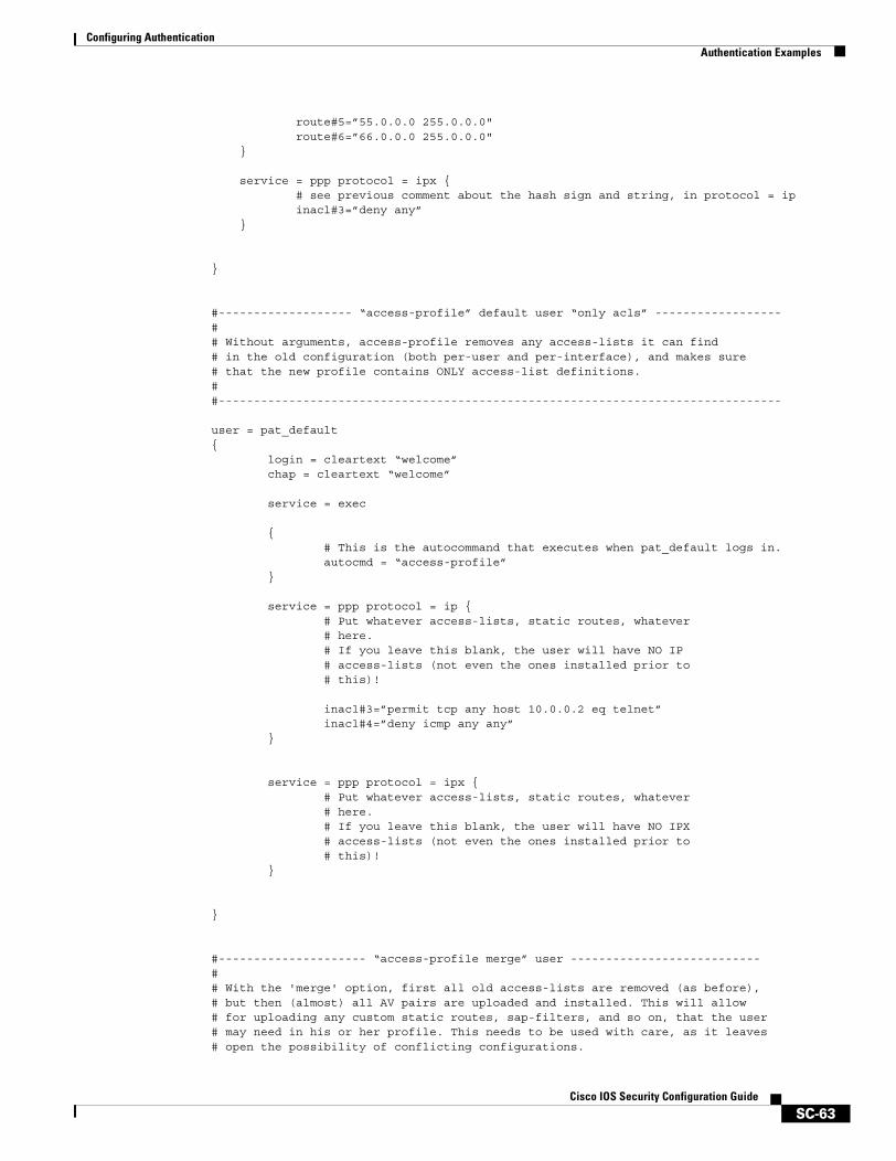
Configuring AuthenticationAuthentication Examples
SC-63Cisco IOS Security Configuration Guide
route#5=”55.0.0.0 255.0.0.0"route#6=”66.0.0.0 255.0.0.0"
}
service = ppp protocol = ipx {# see previous comment about the hash sign and string, in protocol = ipinacl#3=”deny any”
}
}
#------------------- “access-profile” default user “only acls” ------------------## Without arguments, access-profile removes any access-lists it can find# in the old configuration (both per-user and per-interface), and makes sure# that the new profile contains ONLY access-list definitions.##--------------------------------------------------------------------------------
user = pat_default{ login = cleartext “welcome” chap = cleartext “welcome”
service = exec
{ # This is the autocommand that executes when pat_default logs in. autocmd = “access-profile” }
service = ppp protocol = ip { # Put whatever access-lists, static routes, whatever # here. # If you leave this blank, the user will have NO IP # access-lists (not even the ones installed prior to # this)!
inacl#3=”permit tcp any host 10.0.0.2 eq telnet” inacl#4=”deny icmp any any” }
service = ppp protocol = ipx { # Put whatever access-lists, static routes, whatever # here. # If you leave this blank, the user will have NO IPX # access-lists (not even the ones installed prior to # this)! }
}
#--------------------- “access-profile merge” user ---------------------------## With the 'merge' option, first all old access-lists are removed (as before),# but then (almost) all AV pairs are uploaded and installed. This will allow# for uploading any custom static routes, sap-filters, and so on, that the user# may need in his or her profile. This needs to be used with care, as it leaves# open the possibility of conflicting configurations.
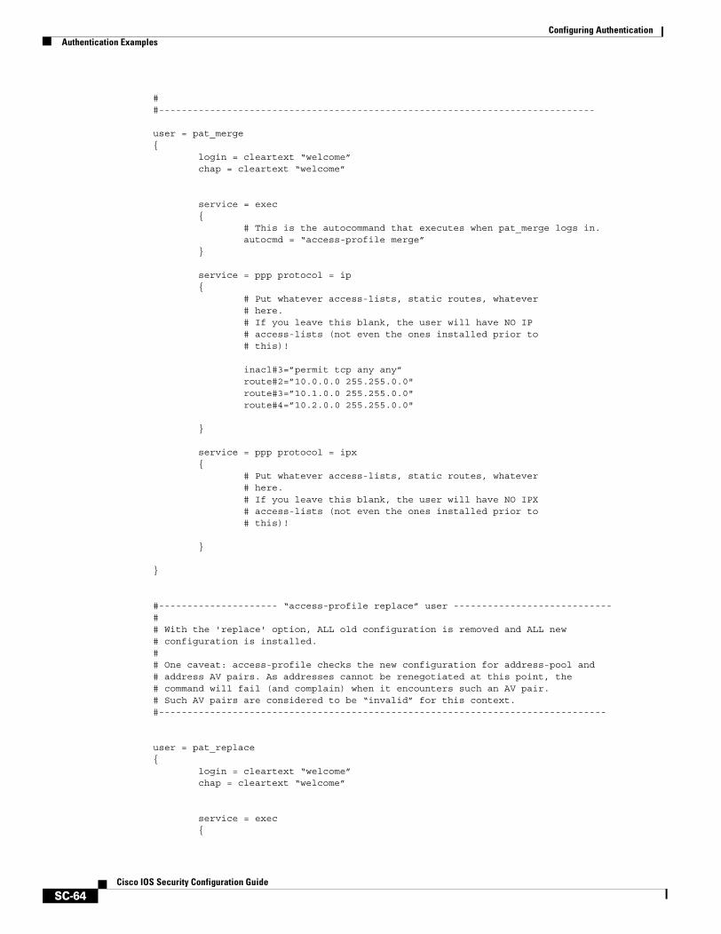
Configuring AuthenticationAuthentication Examples
SC-64Cisco IOS Security Configuration Guide
##-----------------------------------------------------------------------------
user = pat_merge{ login = cleartext “welcome” chap = cleartext “welcome”
service = exec { # This is the autocommand that executes when pat_merge logs in. autocmd = “access-profile merge” }
service = ppp protocol = ip{
# Put whatever access-lists, static routes, whatever # here. # If you leave this blank, the user will have NO IP # access-lists (not even the ones installed prior to # this)!
inacl#3=”permit tcp any any”route#2=”10.0.0.0 255.255.0.0"route#3=”10.1.0.0 255.255.0.0"route#4=”10.2.0.0 255.255.0.0"
}
service = ppp protocol = ipx{
# Put whatever access-lists, static routes, whatever # here. # If you leave this blank, the user will have NO IPX # access-lists (not even the ones installed prior to # this)!
}
}
#--------------------- “access-profile replace” user ----------------------------## With the 'replace' option, ALL old configuration is removed and ALL new # configuration is installed.## One caveat: access-profile checks the new configuration for address-pool and# address AV pairs. As addresses cannot be renegotiated at this point, the# command will fail (and complain) when it encounters such an AV pair.# Such AV pairs are considered to be “invalid” for this context.#-------------------------------------------------------------------------------
user = pat_replace{ login = cleartext “welcome” chap = cleartext “welcome”
service = exec{
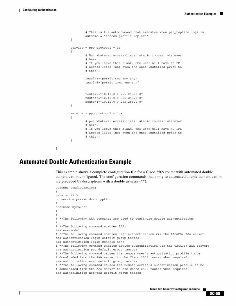
Configuring AuthenticationAuthentication Examples
SC-65Cisco IOS Security Configuration Guide
# This is the autocommand that executes when pat_replace logs in. autocmd = “access-profile replace” }
service = ppp protocol = ip{
# Put whatever access-lists, static routes, whatever # here. # If you leave this blank, the user will have NO IP # access-lists (not even the ones installed prior to # this)!
inacl#3=”permit tcp any any” inacl#4=”permit icmp any any”
route#2=”10.10.0.0 255.255.0.0" route#3=”10.11.0.0 255.255.0.0" route#4=”10.12.0.0 255.255.0.0"
}
service = ppp protocol = ipx{
# put whatever access-lists, static routes, whatever # here. # If you leave this blank, the user will have NO IPX # access-lists (not even the ones installed prior to # this)! }
}
Automated Double Authentication ExampleThis example shows a complete configuration file for a Cisco 2509 router with automated double authentication configured. The configuration commands that apply to automated double authentication are preceded by descriptions with a double asterisk (**).
Current configuration:!version 11.3no service password-encryption!hostname myrouter!!! **The following AAA commands are used to configure double authentication:!! **The following command enables AAA:aaa new-model! **The following command enables user authentication via the TACACS+ AAA server:aaa authentication login default group tacacs+aaa authentication login console none! **The following command enables device authentication via the TACACS+ AAA server:aaa authentication ppp default group tacacs+! **The following command causes the remote user’s authorization profile to be! downloaded from the AAA server to the Cisco 2509 router when required:aaa authorization exec default group tacacs+! **The following command causes the remote device’s authorization profile to be! downloaded from the AAA server to the Cisco 2509 router when required:aaa authorization network default group tacacs+
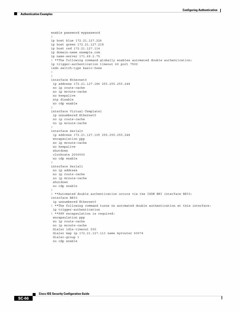
Configuring AuthenticationAuthentication Examples
SC-66Cisco IOS Security Configuration Guide
enable password mypassword!ip host blue 172.21.127.226ip host green 172.21.127.218ip host red 172.21.127.114ip domain-name example.comip name-server 171.69.2.75! **The following command globally enables automated double authentication:ip trigger-authentication timeout 60 port 7500isdn switch-type basic-5ess! ! interface Ethernet0ip address 172.21.127.186 255.255.255.248no ip route-cacheno ip mroute-cacheno keepaliventp disableno cdp enable
! interface Virtual-Template1ip unnumbered Ethernet0no ip route-cacheno ip mroute-cache
! interface Serial0ip address 172.21.127.105 255.255.255.248encapsulation pppno ip mroute-cacheno keepaliveshutdown clockrate 2000000no cdp enable
! interface Serial1no ip addressno ip route-cacheno ip mroute-cacheshutdown no cdp enable
!! **Automated double authentication occurs via the ISDN BRI interface BRI0:interface BRI0ip unnumbered Ethernet0
! **The following command turns on automated double authentication at this interface:ip trigger-authentication
! **PPP encapsulation is required:encapsulation pppno ip route-cacheno ip mroute-cachedialer idle-timeout 500dialer map ip 172.21.127.113 name myrouter 60074dialer-group 1no cdp enable
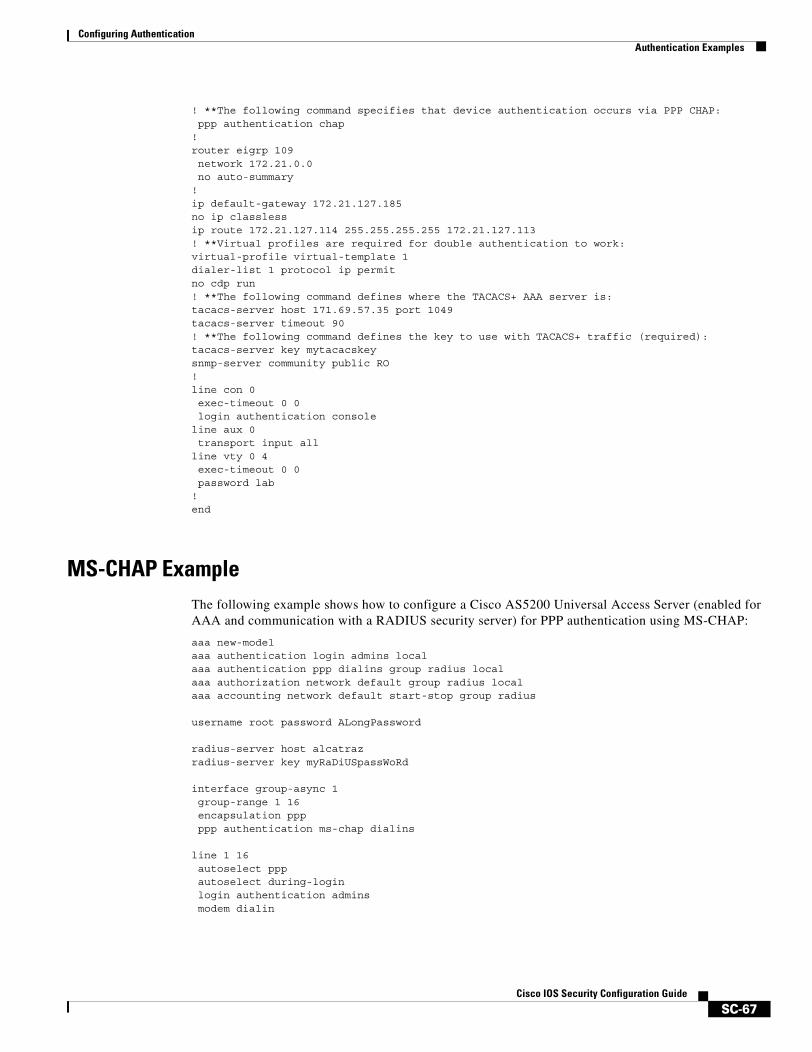
Configuring AuthenticationAuthentication Examples
SC-67Cisco IOS Security Configuration Guide
! **The following command specifies that device authentication occurs via PPP CHAP:ppp authentication chap
! router eigrp 109network 172.21.0.0no auto-summary
! ip default-gateway 172.21.127.185no ip classlessip route 172.21.127.114 255.255.255.255 172.21.127.113! **Virtual profiles are required for double authentication to work:virtual-profile virtual-template 1dialer-list 1 protocol ip permitno cdp run! **The following command defines where the TACACS+ AAA server is:tacacs-server host 171.69.57.35 port 1049tacacs-server timeout 90! **The following command defines the key to use with TACACS+ traffic (required):tacacs-server key mytacacskeysnmp-server community public RO! line con 0exec-timeout 0 0login authentication console
line aux 0transport input all
line vty 0 4exec-timeout 0 0password lab
! end
MS-CHAP ExampleThe following example shows how to configure a Cisco AS5200 Universal Access Server (enabled for AAA and communication with a RADIUS security server) for PPP authentication using MS-CHAP:
aaa new-modelaaa authentication login admins localaaa authentication ppp dialins group radius localaaa authorization network default group radius localaaa accounting network default start-stop group radius
username root password ALongPassword
radius-server host alcatrazradius-server key myRaDiUSpassWoRd
interface group-async 1group-range 1 16encapsulation pppppp authentication ms-chap dialins
line 1 16autoselect pppautoselect during-loginlogin authentication adminsmodem dialin
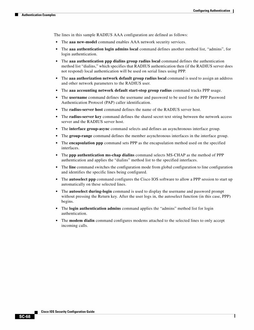
Configuring AuthenticationAuthentication Examples
SC-68Cisco IOS Security Configuration Guide
The lines in this sample RADIUS AAA configuration are defined as follows:
• The aaa new-model command enables AAA network security services.
• The aaa authentication login admins local command defines another method list, “admins”, for login authentication.
• The aaa authentication ppp dialins group radius local command defines the authentication method list “dialins,” which specifies that RADIUS authentication then (if the RADIUS server does not respond) local authentication will be used on serial lines using PPP.
• The aaa authorization network default group radius local command is used to assign an address and other network parameters to the RADIUS user.
• The aaa accounting network default start-stop group radius command tracks PPP usage.
• The username command defines the username and password to be used for the PPP Password Authentication Protocol (PAP) caller identification.
• The radius-server host command defines the name of the RADIUS server host.
• The radius-server key command defines the shared secret text string between the network access server and the RADIUS server host.
• The interface group-async command selects and defines an asynchronous interface group.
• The group-range command defines the member asynchronous interfaces in the interface group.
• The encapsulation ppp command sets PPP as the encapsulation method used on the specified interfaces.
• The ppp authentication ms-chap dialins command selects MS-CHAP as the method of PPP authentication and applies the “dialins” method list to the specified interfaces.
• The line command switches the configuration mode from global configuration to line configuration and identifies the specific lines being configured.
• The autoselect ppp command configures the Cisco IOS software to allow a PPP session to start up automatically on these selected lines.
• The autoselect during-login command is used to display the username and password prompt without pressing the Return key. After the user logs in, the autoselect function (in this case, PPP) begins.
• The login authentication admins command applies the “admins” method list for login authentication.
• The modem dialin command configures modems attached to the selected lines to only accept incoming calls.

SC-69Cisco IOS Security Configuration Guide
Configuring Authorization
AAA authorization enables you to limit the services available to a user. When AAA authorization is enabled, the network access server uses information retrieved from the user’s profile, which is located either in the local user database or on the security server, to configure the user’s session. Once this is done, the user will be granted access to a requested service only if the information in the user profile allows it.
For a complete description of the authorization commands used in this chapter, refer to the chapter “Authorization Commands” in the Cisco IOS Security Command Reference. To locate documentation of other commands that appear in this chapter, use the command reference master index or search online.
To identify the hardware platform or software image information associated with a feature, use the Feature Navigator on Cisco.com to search for information about the feature or refer to the software release notes for a specific release. For more information, see the chapter “Identifying Supported Platforms” section in the “Using Cisco IOS Software.”
In This ChapterThis chapter contains the following sections:
• Named Method Lists for Authorization
• AAA Authorization Methods
• Method Lists and Server Groups
• AAA Authorization Types
• AAA Authorization Prerequisites
• AAA Authorization Configuration Task List
• Authorization Attribute-Value Pairs
• Authorization Configuration Examples
Named Method Lists for AuthorizationMethod lists for authorization define the ways that authorization will be performed and the sequence in which these methods will be performed. A method list is simply a named list describing the authorization methods to be queried (such as RADIUS or TACACS+), in sequence. Method lists enable you to designate one or more security protocols to be used for authorization, thus ensuring a backup system in case the initial method fails. Cisco IOS software uses the first method listed to authorize users for
Configuring AuthorizationAAA Authorization Methods
SC-70Cisco IOS Security Configuration Guide
specific network services; if that method fails to respond, the Cisco IOS software selects the next method listed in the method list. This process continues until there is successful communication with a listed authorization method, or all methods defined are exhausted.
Note The Cisco IOS software attempts authorization with the next listed method only when there is no response from the previous method. If authorization fails at any point in this cycle—meaning that the security server or local username database responds by denying the user services—the authorization process stops and no other authorization methods are attempted.
Method lists are specific to the authorization type requested:
• Auth-proxy—Applies specific security policies on a per-user basis. For detailed information on the authentication proxy feature, refer to the chapter “Configuring Authentication Proxy” in the “Traffic Filtering and Firewalls” part of this book.
• Commands—Applies to the EXEC mode commands a user issues. Command authorization attempts authorization for all EXEC mode commands, including global configuration commands, associated with a specific privilege level.
• EXEC—Applies to the attributes associated with a user EXEC terminal session.
• Network—Applies to network connections. This can include a PPP, SLIP, or ARAP connection.
• Reverse Access—Applies to reverse Telnet sessions.
When you create a named method list, you are defining a particular list of authorization methods for the indicated authorization type.
Once defined, method lists must be applied to specific lines or interfaces before any of the defined methods will be performed. The only exception is the default method list (which is named “default”). If the aaa authorization command for a particular authorization type is issued without a named method list specified, the default method list is automatically applied to all interfaces or lines except those that have a named method list explicitly defined. (A defined method list overrides the default method list.) If no default method list is defined, local authorization takes place by default.
AAA Authorization MethodsAAA supports five different methods of authorization:
• TACACS+—The network access server exchanges authorization information with the TACACS+ security daemon. TACACS+ authorization defines specific rights for users by associating attribute-value pairs, which are stored in a database on the TACACS+ security server, with the appropriate user.
• If-Authenticated—The user is allowed to access the requested function provided the user has been authenticated successfully.
• None—The network access server does not request authorization information; authorization is not performed over this line/interface.
• Local—The router or access server consults its local database, as defined by the username command, for example, to authorize specific rights for users. Only a limited set of functions can be controlled via the local database.
• RADIUS—The network access server requests authorization information from the RADIUS security server. RADIUS authorization defines specific rights for users by associating attributes, which are stored in a database on the RADIUS server, with the appropriate user.
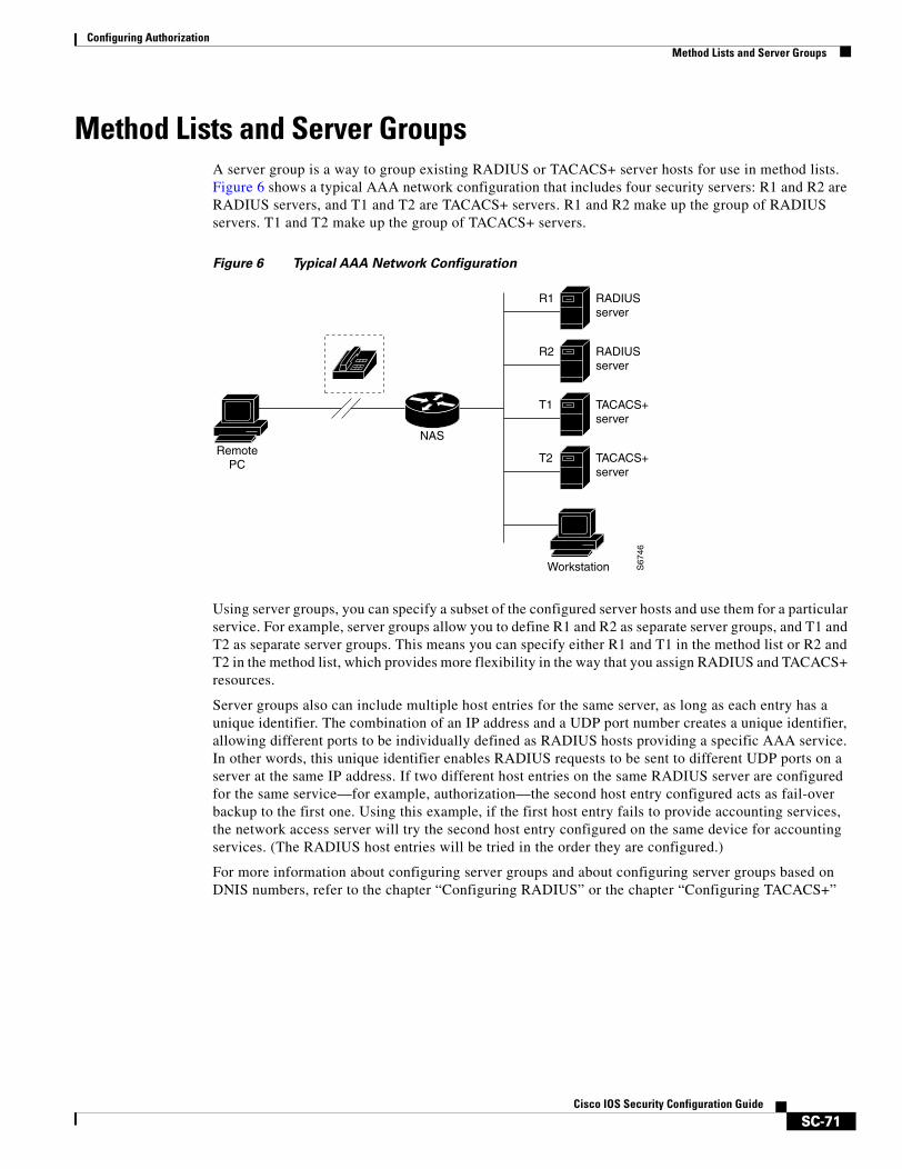
Configuring AuthorizationMethod Lists and Server Groups
SC-71Cisco IOS Security Configuration Guide
Method Lists and Server GroupsA server group is a way to group existing RADIUS or TACACS+ server hosts for use in method lists. Figure 6 shows a typical AAA network configuration that includes four security servers: R1 and R2 are RADIUS servers, and T1 and T2 are TACACS+ servers. R1 and R2 make up the group of RADIUS servers. T1 and T2 make up the group of TACACS+ servers.
Figure 6 Typical AAA Network Configuration
Using server groups, you can specify a subset of the configured server hosts and use them for a particular service. For example, server groups allow you to define R1 and R2 as separate server groups, and T1 and T2 as separate server groups. This means you can specify either R1 and T1 in the method list or R2 and T2 in the method list, which provides more flexibility in the way that you assign RADIUS and TACACS+ resources.
Server groups also can include multiple host entries for the same server, as long as each entry has a unique identifier. The combination of an IP address and a UDP port number creates a unique identifier, allowing different ports to be individually defined as RADIUS hosts providing a specific AAA service. In other words, this unique identifier enables RADIUS requests to be sent to different UDP ports on a server at the same IP address. If two different host entries on the same RADIUS server are configured for the same service—for example, authorization—the second host entry configured acts as fail-over backup to the first one. Using this example, if the first host entry fails to provide accounting services, the network access server will try the second host entry configured on the same device for accounting services. (The RADIUS host entries will be tried in the order they are configured.)
For more information about configuring server groups and about configuring server groups based on DNIS numbers, refer to the chapter “Configuring RADIUS” or the chapter “Configuring TACACS+”
S67
46
RADIUSserver
RADIUSserver
TACACS+server
TACACS+server
R1
R2
T1
T2
NASRemote
PC
Workstation
Configuring AuthorizationAAA Authorization Types
SC-72Cisco IOS Security Configuration Guide
AAA Authorization TypesCisco IOS software supports five different types of authorization:
• Auth-proxy—Applies specific security policies on a per-user basis. For detailed information on the authentication proxy feature, refer to the “Configuring Authentication Proxy” chapter in the “Traffic Filtering and Firewalls” section of this book.
• Commands—Applies to the EXEC mode commands a user issues. Command authorization attempts authorization for all EXEC mode commands, including global configuration commands, associated with a specific privilege level.
• EXEC—Applies to the attributes associated with a user EXEC terminal session.
• Network—Applies to network connections. This can include a PPP, SLIP, or ARAP connection.
• Reverse Access—Applies to reverse Telnet sessions.
• Configuration—Applies to downloading configurations from the AAA server.
• IP Mobile—Applies to authorization for IP mobile services.
AAA Authorization PrerequisitesBefore configuring authorization using named method lists, you must first perform the following tasks:
• Enable AAA on your network access server. For more information about enabling AAA on your Cisco router or access server, refer to the “AAA Overview” chapter.
• Configure AAA authentication. Authorization generally takes place after authentication and relies on authentication to work properly. For more information about AAA authentication, refer to the “Configuring Authentication” chapter.
• Define the characteristics of your RADIUS or TACACS+ security server if you are issuing RADIUS or TACACS+ authorization. For more information about configuring your Cisco network access server to communicate with your RADIUS security server, refer to the chapter “Configuring RADIUS”. For more information about configuring your Cisco network access server to communicate with your TACACS+ security server, refer to the chapter “Configuring TACACS+”.
• Define the rights associated with specific users by using the username command if you are issuing local authorization. For more information about the username command, refer to the Cisco IOS Security Command Reference.
AAA Authorization Configuration Task ListThis section describes the following configuration tasks:
• Configuring AAA Authorization Using Named Method Lists
• Disabling Authorization for Global Configuration Commands
• Configuring Authorization for Reverse Telnet
For authorization configuration examples using the commands in this chapter, refer to the section “Authorization Configuration Examples” at the end of the this chapter.
Configuring AuthorizationAAA Authorization Configuration Task List
SC-73Cisco IOS Security Configuration Guide
Configuring AAA Authorization Using Named Method ListsTo configure AAA authorization using named method lists, use the following commands beginning in global configuration mode:
This section includes the following sections:
• Authorization Types
• Authorization Methods
Authorization Types
Named authorization method lists are specific to the indicated type of authorization.
To create a method list to enable authorization that applies specific security policies on a per-user basis, use the auth-proxy keyword. For detailed information on the authentication proxy feature, refer to the chapter “Configuring Authentication Proxy” in the “Traffic Filtering and Firewalls” part of this book.
To create a method list to enable authorization for all network-related service requests (including SLIP, PPP, PPP NCPs, and ARAP), use the network keyword.
To create a method list to enable authorization to determine if a user is allowed to run an EXEC shell, use the exec keyword.
To create a method list to enable authorization for specific, individual EXEC commands associated with a specific privilege level, use the commands keyword. (This allows you to authorize all commands associated with a specified command level from 0 to 15.)
To create a method list to enable authorization for reverse Telnet functions, use the reverse-access keyword.
For information about the types of authorization supported by the Cisco IOS software, refer to the “AAA Authorization Types” section of this chapter.
Command Purpose
Step 1 Router(config)# aaa authorization {auth-proxy | network | exec | commands level | reverse-access | configuration | ipmobile} {default | list-name} [method1 [method2...]]
Creates an authorization method list for a particular authorization type and enable authorization.
Step 2 Router(config)# line [aux | console | tty | vty] line-number [ending-line-number]
or
Router(config)# interface interface-type interface-number
Enters the line configuration mode for the lines to which you want to apply the authorization method list.
Alternately, enters the interface configuration mode for the interfaces to which you want to apply the authorization method list.
Step 3 Router(config-line)# authorization {arap | commands level | exec | reverse-access} {default | list-name}
orRouter(config-line)# ppp authorization {default | list-name}
Applies the authorization list to a line or set of lines.
Alternately, applies the authorization list to an interface or set of interfaces.

Configuring AuthorizationAAA Authorization Configuration Task List
SC-74Cisco IOS Security Configuration Guide
Authorization Methods
To have the network access server request authorization information via a TACACS+ security server, use the aaa authorization command with the group tacacs+ method keyword. For more specific information about configuring authorization using a TACACS+ security server, refer to the chapter “Configuring TACACS+.” For an example of how to enable a TACACS+ server to authorize the use of network services, including PPP and ARA, see the section “TACACS+ Authorization Examples” at the end of this chapter.
To allow users to have access to the functions they request as long as they have been authenticated, use the aaa authorization command with the if-authenticated method keyword. If you select this method, all requested functions are automatically granted to authenticated users.
There may be times when you do not want to run authorization from a particular interface or line. To stop authorization activities on designated lines or interfaces, use the none method keyword. If you select this method, authorization is disabled for all actions.
To select local authorization, which means that the router or access server consults its local user database to determine the functions a user is permitted to use, use the aaa authorization command with the local method keyword. The functions associated with local authorization are defined by using the username global configuration command. For a list of permitted functions, refer to the chapter “Configuring Authentication.”
To have the network access server request authorization via a RADIUS security server, use the radius method keyword. For more specific information about configuring authorization using a RADIUS security server, refer to the chapter “Configuring RADIUS.”
To have the network access server request authorization via a RADIUS security server, use the aaa authorization command with the group radius method keyword. For more specific information about configuring authorization using a RADIUS security server, refer to the chapter “Configuring RADIUS”. For an example of how to enable a RADIUS server to authorize services, see the “RADIUS Authorization Example” section at the end of this chapter.
Note Authorization method lists for SLIP follow whatever is configured for PPP on the relevant interface. If no lists are defined and applied to a particular interface (or no PPP settings are configured), the default setting for authorization applies.
Disabling Authorization for Global Configuration CommandsThe aaa authorization command with the keyword commands attempts authorization for all EXEC mode commands, including global configuration commands, associated with a specific privilege level. Because there are configuration commands that are identical to some EXEC-level commands, there can be some confusion in the authorization process. Using no aaa authorization config-commands stops the network access server from attempting configuration command authorization.
To disable AAA authorization for all global configuration commands, use the following command in global configuration mode:
Command Purpose
Router(config)# no aaa authorization config-commands Disables authorization for all global configuration commands.
Configuring AuthorizationAuthorization Attribute-Value Pairs
SC-75Cisco IOS Security Configuration Guide
Configuring Authorization for Reverse TelnetTelnet is a standard terminal emulation protocol used for remote terminal connection. Normally, you log in to a network access server (typically through a dialup connection) and then use Telnet to access other network devices from that network access server. There are times, however, when it is necessary to establish a reverse Telnet session. In reverse Telnet sessions, the Telnet connection is established in the opposite direction—from inside a network to a network access server on the network periphery to gain access to modems or other devices connected to that network access server. Reverse Telnet is used to provide users with dialout capability by allowing them to Telnet to modem ports attached to a network access server.
It is important to control access to ports accessible through reverse Telnet. Failure to do so could, for example, allow unauthorized users free access to modems where they can trap and divert incoming calls or make outgoing calls to unauthorized destinations.
Authentication during reverse Telnet is performed through the standard AAA login procedure for Telnet. Typically the user has to provide a username and password to establish either a Telnet or reverse Telnet session. Reverse Telnet authorization provides an additional (optional) level of security by requiring authorization in addition to authentication. When enabled, reverse Telnet authorization can use RADIUS or TACACS+ to authorize whether or not this user is allowed reverse Telnet access to specific asynchronous ports, after the user successfully authenticates through the standard Telnet login procedure.
Reverse Telnet authorization offers the following benefits:
• An additional level of protection by ensuring that users engaged in reverse Telnet activities are indeed authorized to access a specific asynchronous port using reverse Telnet.
• An alternative method (other than access lists) to manage reverse Telnet authorization.
To configure a network access server to request authorization information from a TACACS+ or RADIUS server before allowing a user to establish a reverse Telnet session, use the following command in global configuration mode:
This feature enables the network access server to request reverse Telnet authorization information from the security server, whether RADIUS or TACACS+. You must configure the specific reverse Telnet privileges for the user on the security server itself.
Authorization Attribute-Value PairsRADIUS and TACACS+ authorization both define specific rights for users by processing attributes, which are stored in a database on the security server. For both RADIUS and TACACS+, attributes are defined on the security server, associated with the user, and sent to the network access server where they are applied to the user’s connection.
For a list of supported RADIUS attributes, refer to the appendix “RADIUS Attributes”. For a list of supported TACACS+ AV pairs, refer to the appendix “TACACS+ Attribute-Value Pairs.”
Command PurposeRouter(config)# aaa authorization reverse-access method1 [method2 ...]
Configures the network access server to request authorization information before allowing a user to establish a reverse Telnet session.
Configuring AuthorizationAuthorization Configuration Examples
SC-76Cisco IOS Security Configuration Guide
Authorization Configuration ExamplesThe following sections provide authorization configuration examples:
• Named Method List Configuration Example
• TACACS+ Authorization Examples
• RADIUS Authorization Example
• Reverse Telnet Authorization Examples
Named Method List Configuration ExampleThe following example shows how to configure a Cisco AS5300 (enabled for AAA and communication with a RADIUS security server) for AAA services to be provided by the RADIUS server. If the RADIUS server fails to respond, then the local database will be queried for authentication and authorization information, and accounting services will be handled by a TACACS+ server.
aaa new-modelaaa authentication login admins localaaa authentication ppp dialins group radius localaaa authorization network scoobee group radius localaaa accounting network charley start-stop group radius
username root password ALongPassword
radius-server host alcatrazradius-server key myRaDiUSpassWoRd
interface group-async 1group-range 1 16encapsulation pppppp authentication chap dialinsppp authorization scoobeeppp accounting charley
line 1 16autoselect pppautoselect during-loginlogin authentication adminsmodem dialin
The lines in this sample RADIUS AAA configuration are defined as follows:
• The aaa new-model command enables AAA network security services.
• The aaa authentication login admins local command defines a method list, admins, for login authentication.
• The aaa authentication ppp dialins group radius local command defines the authentication method list “dialins,” which specifies that RADIUS authentication then (if the RADIUS server does not respond) local authentication will be used on serial lines using PPP.
• The aaa authorization network scoobee group radius local command defines the network authorization method list named scoobee, which specifies that RADIUS authorization will be used on serial lines using PPP. If the RADIUS server fails to respond, then local network authorization will be performed.
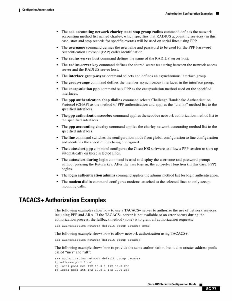
Configuring AuthorizationAuthorization Configuration Examples
SC-77Cisco IOS Security Configuration Guide
• The aaa accounting network charley start-stop group radius command defines the network accounting method list named charley, which specifies that RADIUS accounting services (in this case, start and stop records for specific events) will be used on serial lines using PPP.
• The username command defines the username and password to be used for the PPP Password Authentication Protocol (PAP) caller identification.
• The radius-server host command defines the name of the RADIUS server host.
• The radius-server key command defines the shared secret text string between the network access server and the RADIUS server host.
• The interface group-async command selects and defines an asynchronous interface group.
• The group-range command defines the member asynchronous interfaces in the interface group.
• The encapsulation ppp command sets PPP as the encapsulation method used on the specified interfaces.
• The ppp authentication chap dialins command selects Challenge Handshake Authentication Protocol (CHAP) as the method of PPP authentication and applies the “dialins” method list to the specified interfaces.
• The ppp authorization scoobee command applies the scoobee network authorization method list to the specified interfaces.
• The ppp accounting charley command applies the charley network accounting method list to the specified interfaces.
• The line command switches the configuration mode from global configuration to line configuration and identifies the specific lines being configured.
• The autoselect ppp command configures the Cisco IOS software to allow a PPP session to start up automatically on these selected lines.
• The autoselect during-login command is used to display the username and password prompt without pressing the Return key. After the user logs in, the autoselect function (in this case, PPP) begins.
• The login authentication admins command applies the admins method list for login authentication.
• The modem dialin command configures modems attached to the selected lines to only accept incoming calls.
TACACS+ Authorization ExamplesThe following examples show how to use a TACACS+ server to authorize the use of network services, including PPP and ARA. If the TACACS+ server is not available or an error occurs during the authorization process, the fallback method (none) is to grant all authorization requests:
aaa authorization network default group tacacs+ none
The following example shows how to allow network authorization using TACACS+:
aaa authorization network default group tacacs+
The following example shows how to provide the same authorization, but it also creates address pools called “mci” and “att”:
aaa authorization network default group tacacs+ip address-pool localip local-pool mci 172.16.0.1 172.16.0.255ip local-pool att 172.17.0.1 172.17.0.255
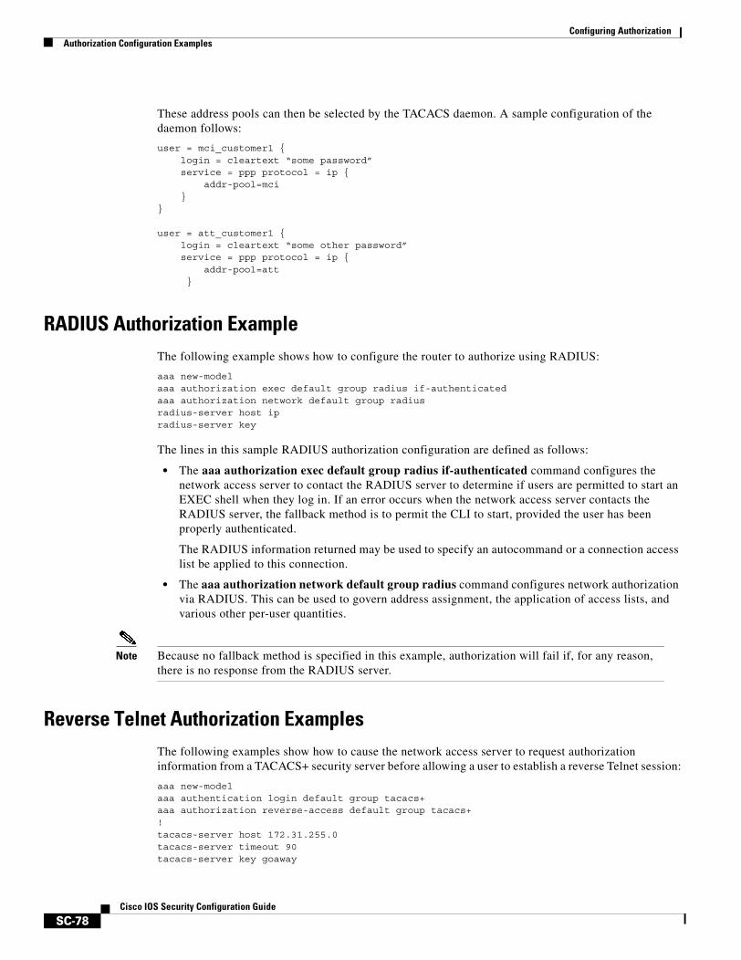
Configuring AuthorizationAuthorization Configuration Examples
SC-78Cisco IOS Security Configuration Guide
These address pools can then be selected by the TACACS daemon. A sample configuration of the daemon follows:
user = mci_customer1 {login = cleartext “some password”service = ppp protocol = ip {
addr-pool=mci}
}
user = att_customer1 {login = cleartext “some other password”service = ppp protocol = ip {
addr-pool=att}
RADIUS Authorization ExampleThe following example shows how to configure the router to authorize using RADIUS:
aaa new-modelaaa authorization exec default group radius if-authenticatedaaa authorization network default group radiusradius-server host ipradius-server key
The lines in this sample RADIUS authorization configuration are defined as follows:
• The aaa authorization exec default group radius if-authenticated command configures the network access server to contact the RADIUS server to determine if users are permitted to start an EXEC shell when they log in. If an error occurs when the network access server contacts the RADIUS server, the fallback method is to permit the CLI to start, provided the user has been properly authenticated.
The RADIUS information returned may be used to specify an autocommand or a connection access list be applied to this connection.
• The aaa authorization network default group radius command configures network authorization via RADIUS. This can be used to govern address assignment, the application of access lists, and various other per-user quantities.
Note Because no fallback method is specified in this example, authorization will fail if, for any reason, there is no response from the RADIUS server.
Reverse Telnet Authorization ExamplesThe following examples show how to cause the network access server to request authorization information from a TACACS+ security server before allowing a user to establish a reverse Telnet session:
aaa new-modelaaa authentication login default group tacacs+aaa authorization reverse-access default group tacacs+!tacacs-server host 172.31.255.0tacacs-server timeout 90tacacs-server key goaway
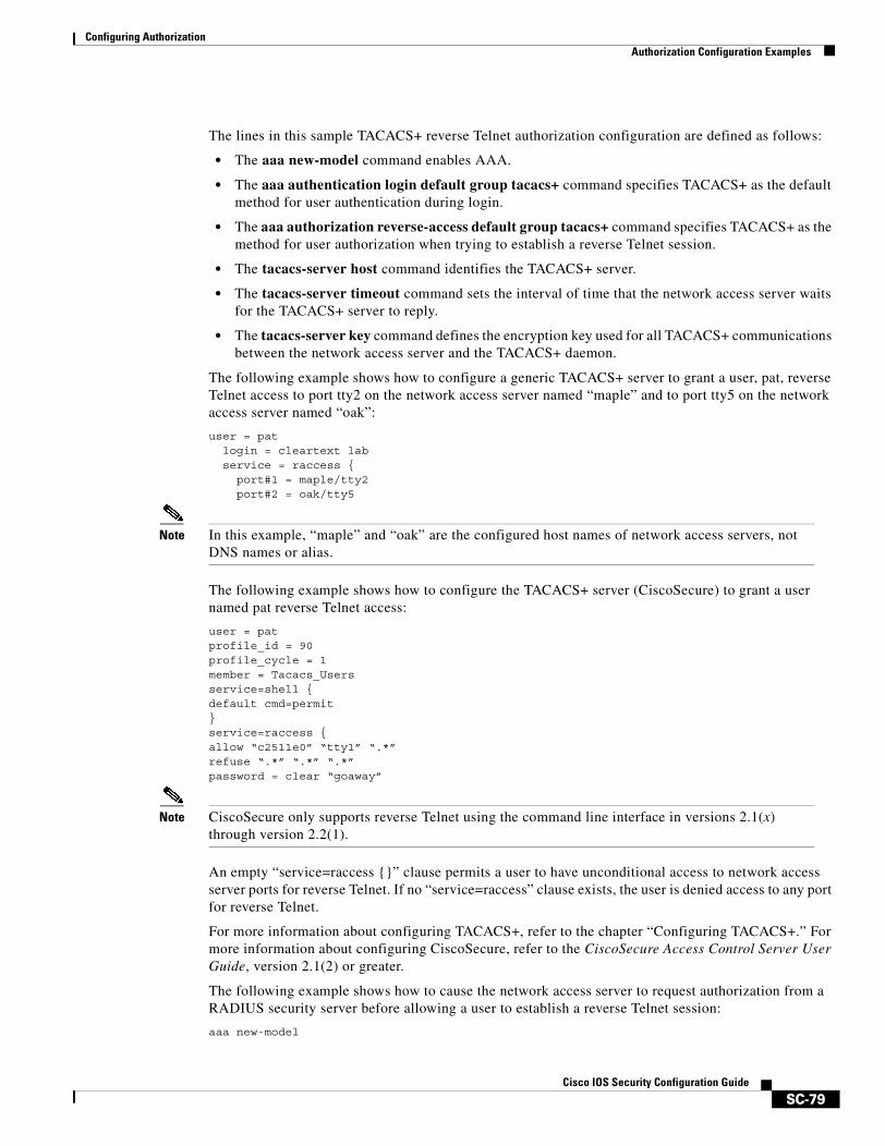
Configuring AuthorizationAuthorization Configuration Examples
SC-79Cisco IOS Security Configuration Guide
The lines in this sample TACACS+ reverse Telnet authorization configuration are defined as follows:
• The aaa new-model command enables AAA.
• The aaa authentication login default group tacacs+ command specifies TACACS+ as the default method for user authentication during login.
• The aaa authorization reverse-access default group tacacs+ command specifies TACACS+ as the method for user authorization when trying to establish a reverse Telnet session.
• The tacacs-server host command identifies the TACACS+ server.
• The tacacs-server timeout command sets the interval of time that the network access server waits for the TACACS+ server to reply.
• The tacacs-server key command defines the encryption key used for all TACACS+ communications between the network access server and the TACACS+ daemon.
The following example shows how to configure a generic TACACS+ server to grant a user, pat, reverse Telnet access to port tty2 on the network access server named “maple” and to port tty5 on the network access server named “oak”:
user = patlogin = cleartext labservice = raccess {
port#1 = maple/tty2port#2 = oak/tty5
Note In this example, “maple” and “oak” are the configured host names of network access servers, not DNS names or alias.
The following example shows how to configure the TACACS+ server (CiscoSecure) to grant a user named pat reverse Telnet access:
user = patprofile_id = 90profile_cycle = 1member = Tacacs_Usersservice=shell {default cmd=permit}service=raccess {allow “c2511e0” “tty1” “.*”refuse “.*” “.*” “.*”password = clear “goaway”
Note CiscoSecure only supports reverse Telnet using the command line interface in versions 2.1(x) through version 2.2(1).
An empty “service=raccess {}” clause permits a user to have unconditional access to network access server ports for reverse Telnet. If no “service=raccess” clause exists, the user is denied access to any port for reverse Telnet.
For more information about configuring TACACS+, refer to the chapter “Configuring TACACS+.” For more information about configuring CiscoSecure, refer to the CiscoSecure Access Control Server User Guide, version 2.1(2) or greater.
The following example shows how to cause the network access server to request authorization from a RADIUS security server before allowing a user to establish a reverse Telnet session:
aaa new-model

Configuring AuthorizationAuthorization Configuration Examples
SC-80Cisco IOS Security Configuration Guide
aaa authentication login default group radiusaaa authorization reverse-access default group radius!radius-server host 172.31.255.0radius-server key go awayauth-port 1645 acct-port 1646
The lines in this sample RADIUS reverse Telnet authorization configuration are defined as follows:
• The aaa new-model command enables AAA.
• The aaa authentication login default group radius command specifies RADIUS as the default method for user authentication during login.
• The aaa authorization reverse-access default group radius command specifies RADIUS as the method for user authorization when trying to establish a reverse Telnet session.
• The radius-server host command identifies the RADIUS server.
• The radius-server key command defines the encryption key used for all RADIUS communications between the network access server and the RADIUS daemon.
The following example shows how to send a request to the RADIUS server to grant a user named “pat” reverse Telnet access at port tty2 on the network access server named “maple”:
Username = “pat”Password = “goaway”User-Service-Type = Shell-Usercisco-avpair = “raccess:port#1=maple/tty2”
An empty “raccess:port#1=nasname1/tty2” clause permits a user to have unconditional access to network access server ports for reverse Telnet. If no “raccess:port#1=nasname1/tty2” clause exists, the user is denied access to any port for reverse Telnet.
For more information about configuring RADIUS, refer to the chapter “Configuring RADIUS.”
SC-81Cisco IOS Security Configuration Guide
Configuring Accounting
The AAA accounting feature enables you to track the services that users are accessing and the amount of network resources that they are consuming. When AAA accounting is enabled, the network access server reports user activity to the TACACS+ or RADIUS security server (depending on which security method you have implemented) in the form of accounting records. Each accounting record contains accounting attribute-value (AV) pairs and is stored on the security server. This data can then be analyzed for network management, client billing, and auditing.
For a complete description of the accounting commands used in this chapter, refer to the chapter “Accounting Commands” in the Cisco IOS Security Command Reference. To locate documentation of other commands that appear in this chapter, use the command reference master index or search online.
To identify the hardware platform or software image information associated with a feature, use the Feature Navigator on Cisco.com to search for information about the feature or refer to the software release notes for a specific release. For more information, see the chapter “Identifying Supported Platforms” section in the “Using Cisco IOS Software.”
In This ChapterThis chapter contains the following sections:
• Named Method Lists for Accounting
• AAA Accounting Types
• AAA Accounting Enhancements
• AAA Accounting Prerequisites
• AAA Accounting Configuration Task List
• Accounting Attribute-Value Pairs
• Accounting Configuration Examples
Named Method Lists for AccountingLike authentication and authorization method lists, method lists for accounting define the way accounting will be performed and the sequence in which these methods are performed.
Configuring AccountingNamed Method Lists for Accounting
SC-82Cisco IOS Security Configuration Guide
Named accounting method lists enable you to designate a particular security protocol to be used on specific lines or interfaces for accounting services. The only exception is the default method list (which, by coincidence, is named “default”). The default method list is automatically applied to all interfaces except those that have a named method list explicitly defined. A defined method list overrides the default method list.
A method list is simply a named list describing the accounting methods to be queried (such as RADIUS or TACACS+), in sequence. Method lists enable you to designate one or more security protocols to be used for accounting, thus ensuring a backup system for accounting in case the initial method fails. Cisco IOS software uses the first method listed to support accounting; if that method fails to respond, the Cisco IOS software selects the next accounting method listed in the method list. This process continues until there is successful communication with a listed accounting method, or all methods defined are exhausted.
Note The Cisco IOS software attempts accounting with the next listed accounting method only when there is no response from the previous method. If accounting fails at any point in this cycle—meaning that the security server responds by denying the user access—the accounting process stops and no other accounting methods are attempted.
Accounting method lists are specific to the type of accounting being requested. AAA supports six different types of accounting:
• Network—Provides information for all PPP, SLIP, or ARAP sessions, including packet and byte counts.
• EXEC—Provides information about user EXEC terminal sessions of the network access server.
• Commands—Provides information about the EXEC mode commands that a user issues. Command accounting generates accounting records for all EXEC mode commands, including global configuration commands, associated with a specific privilege level.
• Connection—Provides information about all outbound connections made from the network access server, such as Telnet, local-area transport (LAT), TN3270, packet assembler/disassembler (PAD), and rlogin.
• System—Provides information about system-level events.
• Resource—Provides “start” and “stop” records for calls that have passed user authentication, and provides “stop” records for calls that fail to authenticate.
Note System accounting does not use named accounting lists; you can only define the default list for system accounting.
Once again, when you create a named method list, you are defining a particular list of accounting methods for the indicated accounting type.
Accounting method lists must be applied to specific lines or interfaces before any of the defined methods will be performed. The only exception is the default method list (which is named “default”). If the aaa accounting command for a particular accounting type is issued without a named method list specified, the default method list is automatically applied to all interfaces or lines except those that have a named method list explicitly defined. (A defined method list overrides the default method list.) If no default method list is defined, then no accounting takes place.
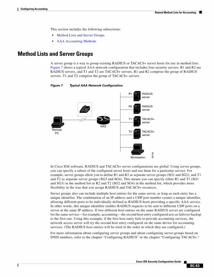
Configuring AccountingNamed Method Lists for Accounting
SC-83Cisco IOS Security Configuration Guide
This section includes the following subsections:
• Method Lists and Server Groups
• AAA Accounting Methods
Method Lists and Server GroupsA server group is a way to group existing RADIUS or TACACS+ server hosts for use in method lists. Figure 7 shows a typical AAA network configuration that includes four security servers: R1 and R2 are RADIUS servers, and T1 and T2 are TACACS+ servers. R1 and R2 comprise the group of RADIUS servers. T1 and T2 comprise the group of TACACS+ servers.
Figure 7 Typical AAA Network Configuration
In Cisco IOS software, RADIUS and TACACS+ server configurations are global. Using server groups, you can specify a subset of the configured server hosts and use them for a particular service. For example, server groups allow you to define R1 and R2 as separate server groups (SG1 and SG2), and T1 and T2 as separate server groups (SG3 and SG4). This means you can specify either R1 and T1 (SG1 and SG3) in the method list or R2 and T2 (SG2 and SG4) in the method list, which provides more flexibility in the way that you assign RADIUS and TACACS+ resources.
Server groups also can include multiple host entries for the same server, as long as each entry has a unique identifier. The combination of an IP address and a UDP port number creates a unique identifier, allowing different ports to be individually defined as RADIUS hosts providing a specific AAA service. In other words, this unique identifier enables RADIUS requests to be sent to different UDP ports on a server at the same IP address. If two different host entries on the same RADIUS server are configured for the same service—for example, accounting—the second host entry configured acts as failover backup to the first one. Using this example, if the first host entry fails to provide accounting services, the network access server will try the second host entry configured on the same device for accounting services. (The RADIUS host entries will be tried in the order in which they are configured.)
For more information about configuring server groups and about configuring server groups based on DNIS numbers, refer to the chapter “Configuring RADIUS” or the chapter “Configuring TACACS+.”
S67
46
RADIUSserver
RADIUSserver
TACACS+server
TACACS+server
R1
R2
T1
T2
NASRemote
PC
Workstation
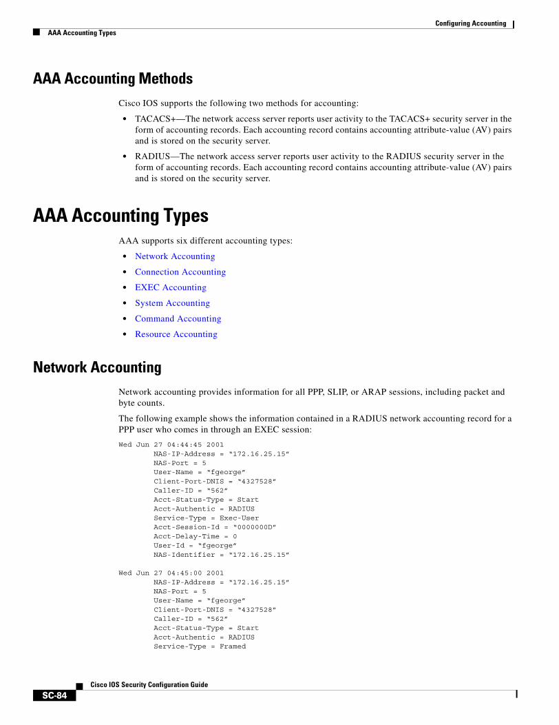
Configuring AccountingAAA Accounting Types
SC-84Cisco IOS Security Configuration Guide
AAA Accounting MethodsCisco IOS supports the following two methods for accounting:
• TACACS+—The network access server reports user activity to the TACACS+ security server in the form of accounting records. Each accounting record contains accounting attribute-value (AV) pairs and is stored on the security server.
• RADIUS—The network access server reports user activity to the RADIUS security server in the form of accounting records. Each accounting record contains accounting attribute-value (AV) pairs and is stored on the security server.
AAA Accounting TypesAAA supports six different accounting types:
• Network Accounting
• Connection Accounting
• EXEC Accounting
• System Accounting
• Command Accounting
• Resource Accounting
Network AccountingNetwork accounting provides information for all PPP, SLIP, or ARAP sessions, including packet and byte counts.
The following example shows the information contained in a RADIUS network accounting record for a PPP user who comes in through an EXEC session:
Wed Jun 27 04:44:45 2001 NAS-IP-Address = “172.16.25.15” NAS-Port = 5 User-Name = “fgeorge” Client-Port-DNIS = “4327528” Caller-ID = “562” Acct-Status-Type = Start Acct-Authentic = RADIUS Service-Type = Exec-User Acct-Session-Id = “0000000D” Acct-Delay-Time = 0 User-Id = “fgeorge” NAS-Identifier = “172.16.25.15” Wed Jun 27 04:45:00 2001 NAS-IP-Address = “172.16.25.15” NAS-Port = 5 User-Name = “fgeorge” Client-Port-DNIS = “4327528” Caller-ID = “562” Acct-Status-Type = Start Acct-Authentic = RADIUS Service-Type = Framed
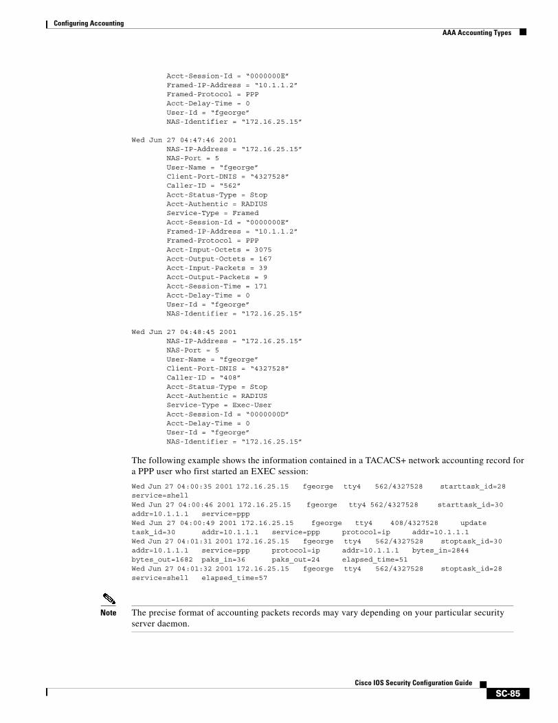
Configuring AccountingAAA Accounting Types
SC-85Cisco IOS Security Configuration Guide
Acct-Session-Id = “0000000E” Framed-IP-Address = “10.1.1.2” Framed-Protocol = PPP Acct-Delay-Time = 0 User-Id = “fgeorge” NAS-Identifier = “172.16.25.15”
Wed Jun 27 04:47:46 2001 NAS-IP-Address = “172.16.25.15” NAS-Port = 5 User-Name = “fgeorge” Client-Port-DNIS = “4327528” Caller-ID = “562” Acct-Status-Type = Stop Acct-Authentic = RADIUS Service-Type = Framed Acct-Session-Id = “0000000E” Framed-IP-Address = “10.1.1.2” Framed-Protocol = PPP Acct-Input-Octets = 3075 Acct-Output-Octets = 167 Acct-Input-Packets = 39 Acct-Output-Packets = 9 Acct-Session-Time = 171 Acct-Delay-Time = 0 User-Id = “fgeorge” NAS-Identifier = “172.16.25.15”
Wed Jun 27 04:48:45 2001 NAS-IP-Address = “172.16.25.15” NAS-Port = 5 User-Name = “fgeorge” Client-Port-DNIS = “4327528” Caller-ID = “408” Acct-Status-Type = Stop Acct-Authentic = RADIUS Service-Type = Exec-User Acct-Session-Id = “0000000D” Acct-Delay-Time = 0 User-Id = “fgeorge” NAS-Identifier = “172.16.25.15”
The following example shows the information contained in a TACACS+ network accounting record for a PPP user who first started an EXEC session:
Wed Jun 27 04:00:35 2001 172.16.25.15 fgeorge tty4 562/4327528 starttask_id=28 service=shellWed Jun 27 04:00:46 2001 172.16.25.15 fgeorge tty4 562/4327528 starttask_id=30 addr=10.1.1.1 service=pppWed Jun 27 04:00:49 2001 172.16.25.15 fgeorge tty4 408/4327528 update task_id=30 addr=10.1.1.1 service=ppp protocol=ip addr=10.1.1.1Wed Jun 27 04:01:31 2001 172.16.25.15 fgeorge tty4 562/4327528 stoptask_id=30 addr=10.1.1.1 service=ppp protocol=ip addr=10.1.1.1 bytes_in=2844 bytes_out=1682 paks_in=36 paks_out=24 elapsed_time=51Wed Jun 27 04:01:32 2001 172.16.25.15 fgeorge tty4 562/4327528 stoptask_id=28 service=shell elapsed_time=57
Note The precise format of accounting packets records may vary depending on your particular security server daemon.
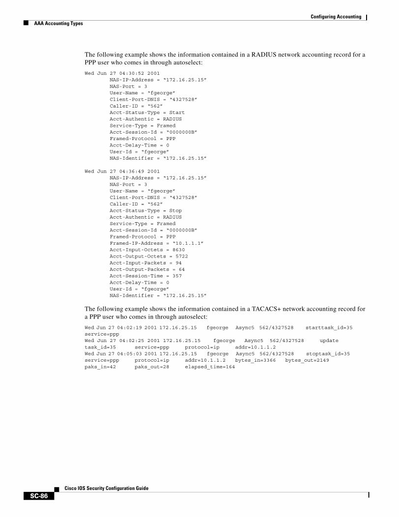
Configuring AccountingAAA Accounting Types
SC-86Cisco IOS Security Configuration Guide
The following example shows the information contained in a RADIUS network accounting record for a PPP user who comes in through autoselect:
Wed Jun 27 04:30:52 2001 NAS-IP-Address = “172.16.25.15” NAS-Port = 3 User-Name = “fgeorge” Client-Port-DNIS = “4327528” Caller-ID = “562” Acct-Status-Type = Start Acct-Authentic = RADIUS Service-Type = Framed Acct-Session-Id = “0000000B” Framed-Protocol = PPP Acct-Delay-Time = 0 User-Id = “fgeorge” NAS-Identifier = “172.16.25.15” Wed Jun 27 04:36:49 2001 NAS-IP-Address = “172.16.25.15” NAS-Port = 3 User-Name = “fgeorge” Client-Port-DNIS = “4327528” Caller-ID = “562” Acct-Status-Type = Stop Acct-Authentic = RADIUS Service-Type = Framed Acct-Session-Id = “0000000B” Framed-Protocol = PPP Framed-IP-Address = “10.1.1.1” Acct-Input-Octets = 8630 Acct-Output-Octets = 5722 Acct-Input-Packets = 94 Acct-Output-Packets = 64 Acct-Session-Time = 357 Acct-Delay-Time = 0 User-Id = “fgeorge” NAS-Identifier = “172.16.25.15”
The following example shows the information contained in a TACACS+ network accounting record for a PPP user who comes in through autoselect:
Wed Jun 27 04:02:19 2001 172.16.25.15 fgeorge Async5 562/4327528 starttask_id=35 service=pppWed Jun 27 04:02:25 2001 172.16.25.15 fgeorge Async5 562/4327528 update task_id=35 service=ppp protocol=ip addr=10.1.1.2Wed Jun 27 04:05:03 2001 172.16.25.15 fgeorge Async5 562/4327528 stoptask_id=35 service=ppp protocol=ip addr=10.1.1.2 bytes_in=3366 bytes_out=2149 paks_in=42 paks_out=28 elapsed_time=164
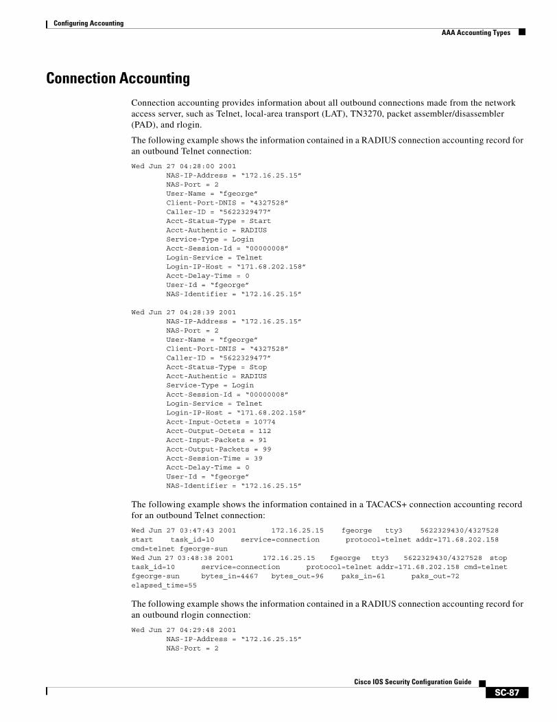
Configuring AccountingAAA Accounting Types
SC-87Cisco IOS Security Configuration Guide
Connection AccountingConnection accounting provides information about all outbound connections made from the network access server, such as Telnet, local-area transport (LAT), TN3270, packet assembler/disassembler (PAD), and rlogin.
The following example shows the information contained in a RADIUS connection accounting record for an outbound Telnet connection:
Wed Jun 27 04:28:00 2001 NAS-IP-Address = “172.16.25.15” NAS-Port = 2 User-Name = “fgeorge” Client-Port-DNIS = “4327528” Caller-ID = “5622329477” Acct-Status-Type = Start Acct-Authentic = RADIUS Service-Type = Login Acct-Session-Id = “00000008” Login-Service = Telnet Login-IP-Host = “171.68.202.158” Acct-Delay-Time = 0 User-Id = “fgeorge” NAS-Identifier = “172.16.25.15” Wed Jun 27 04:28:39 2001 NAS-IP-Address = “172.16.25.15” NAS-Port = 2 User-Name = “fgeorge” Client-Port-DNIS = “4327528” Caller-ID = “5622329477” Acct-Status-Type = Stop Acct-Authentic = RADIUS Service-Type = Login Acct-Session-Id = “00000008” Login-Service = Telnet Login-IP-Host = “171.68.202.158” Acct-Input-Octets = 10774 Acct-Output-Octets = 112 Acct-Input-Packets = 91 Acct-Output-Packets = 99 Acct-Session-Time = 39 Acct-Delay-Time = 0 User-Id = “fgeorge” NAS-Identifier = “172.16.25.15”
The following example shows the information contained in a TACACS+ connection accounting record for an outbound Telnet connection:
Wed Jun 27 03:47:43 2001 172.16.25.15 fgeorge tty3 5622329430/4327528 start task_id=10 service=connection protocol=telnet addr=171.68.202.158 cmd=telnet fgeorge-sunWed Jun 27 03:48:38 2001 172.16.25.15 fgeorge tty3 5622329430/4327528 stop task_id=10 service=connection protocol=telnet addr=171.68.202.158 cmd=telnet fgeorge-sun bytes_in=4467 bytes_out=96 paks_in=61 paks_out=72 elapsed_time=55
The following example shows the information contained in a RADIUS connection accounting record for an outbound rlogin connection:
Wed Jun 27 04:29:48 2001 NAS-IP-Address = “172.16.25.15” NAS-Port = 2
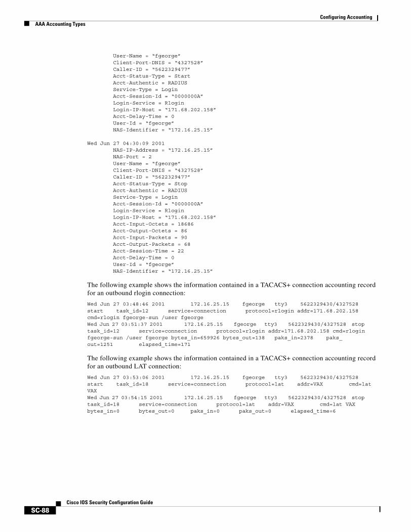
Configuring AccountingAAA Accounting Types
SC-88Cisco IOS Security Configuration Guide
User-Name = “fgeorge” Client-Port-DNIS = “4327528” Caller-ID = “5622329477” Acct-Status-Type = Start Acct-Authentic = RADIUS Service-Type = Login Acct-Session-Id = “0000000A” Login-Service = Rlogin Login-IP-Host = “171.68.202.158” Acct-Delay-Time = 0 User-Id = “fgeorge” NAS-Identifier = “172.16.25.15” Wed Jun 27 04:30:09 2001 NAS-IP-Address = “172.16.25.15” NAS-Port = 2 User-Name = “fgeorge” Client-Port-DNIS = “4327528” Caller-ID = “5622329477” Acct-Status-Type = Stop Acct-Authentic = RADIUS Service-Type = Login Acct-Session-Id = “0000000A” Login-Service = Rlogin Login-IP-Host = “171.68.202.158” Acct-Input-Octets = 18686 Acct-Output-Octets = 86 Acct-Input-Packets = 90 Acct-Output-Packets = 68 Acct-Session-Time = 22 Acct-Delay-Time = 0 User-Id = “fgeorge” NAS-Identifier = “172.16.25.15”
The following example shows the information contained in a TACACS+ connection accounting record for an outbound rlogin connection:
Wed Jun 27 03:48:46 2001 172.16.25.15 fgeorge tty3 5622329430/4327528 start task_id=12 service=connection protocol=rlogin addr=171.68.202.158 cmd=rlogin fgeorge-sun /user fgeorgeWed Jun 27 03:51:37 2001 172.16.25.15 fgeorge tty3 5622329430/4327528 stop task_id=12 service=connection protocol=rlogin addr=171.68.202.158 cmd=rlogin fgeorge-sun /user fgeorge bytes_in=659926 bytes_out=138 paks_in=2378 paks_out=1251 elapsed_time=171
The following example shows the information contained in a TACACS+ connection accounting record for an outbound LAT connection:
Wed Jun 27 03:53:06 2001 172.16.25.15 fgeorge tty3 5622329430/4327528 start task_id=18 service=connection protocol=lat addr=VAX cmd=lat VAXWed Jun 27 03:54:15 2001 172.16.25.15 fgeorge tty3 5622329430/4327528 stop task_id=18 service=connection protocol=lat addr=VAX cmd=lat VAX bytes_in=0 bytes_out=0 paks_in=0 paks_out=0 elapsed_time=6
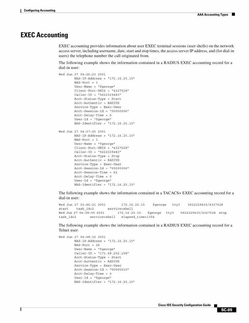
Configuring AccountingAAA Accounting Types
SC-89Cisco IOS Security Configuration Guide
EXEC AccountingEXEC accounting provides information about user EXEC terminal sessions (user shells) on the network access server, including username, date, start and stop times, the access server IP address, and (for dial-in users) the telephone number the call originated from.
The following example shows the information contained in a RADIUS EXEC accounting record for a dial-in user:
Wed Jun 27 04:26:23 2001 NAS-IP-Address = “172.16.25.15” NAS-Port = 1 User-Name = “fgeorge” Client-Port-DNIS = “4327528” Caller-ID = “5622329483” Acct-Status-Type = Start Acct-Authentic = RADIUS Service-Type = Exec-User Acct-Session-Id = “00000006” Acct-Delay-Time = 0 User-Id = “fgeorge” NAS-Identifier = “172.16.25.15”
Wed Jun 27 04:27:25 2001 NAS-IP-Address = “172.16.25.15” NAS-Port = 1 User-Name = “fgeorge” Client-Port-DNIS = “4327528” Caller-ID = “5622329483” Acct-Status-Type = Stop Acct-Authentic = RADIUS Service-Type = Exec-User Acct-Session-Id = “00000006” Acct-Session-Time = 62 Acct-Delay-Time = 0 User-Id = “fgeorge” NAS-Identifier = “172.16.25.15”
The following example shows the information contained in a TACACS+ EXEC accounting record for a dial-in user:
Wed Jun 27 03:46:21 2001 172.16.25.15 fgeorge tty3 5622329430/4327528 start task_id=2 service=shellWed Jun 27 04:08:55 2001 172.16.25.15 fgeorge tty3 5622329430/4327528 stop task_id=2 service=shell elapsed_time=1354
The following example shows the information contained in a RADIUS EXEC accounting record for a Telnet user:
Wed Jun 27 04:48:32 2001 NAS-IP-Address = “172.16.25.15” NAS-Port = 26 User-Name = “fgeorge” Caller-ID = “171.68.202.158” Acct-Status-Type = Start Acct-Authentic = RADIUS Service-Type = Exec-User Acct-Session-Id = “00000010” Acct-Delay-Time = 0 User-Id = “fgeorge” NAS-Identifier = “172.16.25.15”
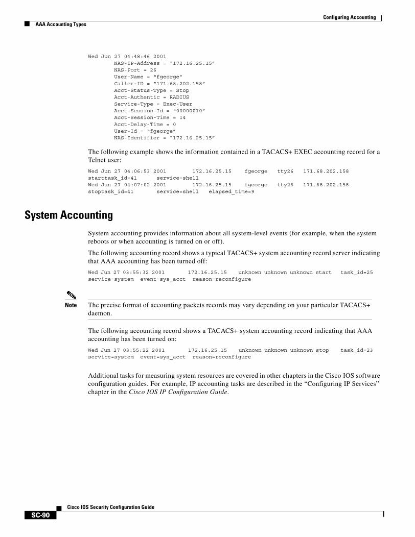
Configuring AccountingAAA Accounting Types
SC-90Cisco IOS Security Configuration Guide
Wed Jun 27 04:48:46 2001 NAS-IP-Address = “172.16.25.15” NAS-Port = 26 User-Name = “fgeorge” Caller-ID = “171.68.202.158” Acct-Status-Type = Stop Acct-Authentic = RADIUS Service-Type = Exec-User Acct-Session-Id = “00000010” Acct-Session-Time = 14 Acct-Delay-Time = 0 User-Id = “fgeorge” NAS-Identifier = “172.16.25.15”
The following example shows the information contained in a TACACS+ EXEC accounting record for a Telnet user:
Wed Jun 27 04:06:53 2001 172.16.25.15 fgeorge tty26 171.68.202.158 starttask_id=41 service=shellWed Jun 27 04:07:02 2001 172.16.25.15 fgeorge tty26 171.68.202.158 stoptask_id=41 service=shell elapsed_time=9
System AccountingSystem accounting provides information about all system-level events (for example, when the system reboots or when accounting is turned on or off).
The following accounting record shows a typical TACACS+ system accounting record server indicating that AAA accounting has been turned off:
Wed Jun 27 03:55:32 2001 172.16.25.15 unknown unknown unknown start task_id=25 service=system event=sys_acct reason=reconfigure
Note The precise format of accounting packets records may vary depending on your particular TACACS+ daemon.
The following accounting record shows a TACACS+ system accounting record indicating that AAA accounting has been turned on:
Wed Jun 27 03:55:22 2001 172.16.25.15 unknown unknown unknown stop task_id=23 service=system event=sys_acct reason=reconfigure
Additional tasks for measuring system resources are covered in other chapters in the Cisco IOS software configuration guides. For example, IP accounting tasks are described in the “Configuring IP Services” chapter in the Cisco IOS IP Configuration Guide.

Configuring AccountingAAA Accounting Types
SC-91Cisco IOS Security Configuration Guide
Command AccountingCommand accounting provides information about the EXEC shell commands for a specified privilege level that are being executed on a network access server. Each command accounting record includes a list of the commands executed for that privilege level, as well as the date and time each command was executed, and the user who executed it.
The following example shows the information contained in a TACACS+ command accounting record for privilege level 1:
Wed Jun 27 03:46:47 2001 172.16.25.15 fgeorge tty3 5622329430/4327528 stop task_id=3 service=shell priv-lvl=1 cmd=show version <cr>Wed Jun 27 03:46:58 2001 172.16.25.15 fgeorge tty3 5622329430/4327528 stop task_id=4 service=shell priv-lvl=1 cmd=show interfaces Ethernet 0 <cr>Wed Jun 27 03:47:03 2001 172.16.25.15 fgeorge tty3 5622329430/4327528 stop task_id=5 service=shell priv-lvl=1 cmd=show ip route <cr>
The following example shows the information contained in a TACACS+ command accounting record for privilege level 15:
Wed Jun 27 03:47:17 2001 172.16.25.15 fgeorge tty3 5622329430/4327528 stop task_id=6 service=shell priv-lvl=15 cmd=configure terminal <cr>Wed Jun 27 03:47:21 2001 172.16.25.15 fgeorge tty3 5622329430/4327528 stop task_id=7 service=shell priv-lvl=15 cmd=interface Serial 0 <cr>Wed Jun 27 03:47:29 2001 172.16.25.15 fgeorge tty3 5622329430/4327528 stop task_id=8 service=shell priv-lvl=15 cmd=ip address 1.1.1.1 255.255.255.0 <cr>
Note The Cisco Systems implementation of RADIUS does not support command accounting.
Resource AccountingThe Cisco implementation of AAA accounting provides “start” and “stop” record support for calls that have passed user authentication. The additional feature of generating “stop” records for calls that fail to authenticate as part of user authentication is also supported. Such records are necessary for users employing accounting records to manage and monitor their networks.
This section includes the following subsections:
• AAA Resource Failure Stop Accounting
• AAA Resource Accounting for Start-Stop Records
AAA Resource Failure Stop Accounting
Before AAA resource failure stop accounting, there was no method of providing accounting records for calls that failed to reach the user authentication stage of a call setup sequence. Such records are necessary for users employing accounting records to manage and monitor their networks and their wholesale customers.
This functionality will generate a “stop” accounting record for any calls that do not reach user authentication; “stop” records will be generated from the moment of call setup. All calls that pass user authentication will behave as before; that is, no additional accounting records will be seen.
Note For Cisco IOS Release 12.2, this function is supported only on the Cisco AS5300 and Cisco AS5800.
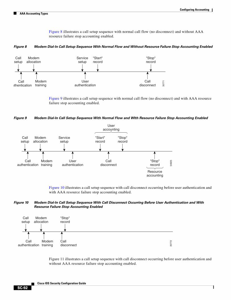
Configuring AccountingAAA Accounting Types
SC-92Cisco IOS Security Configuration Guide
Figure 8 illustrates a call setup sequence with normal call flow (no disconnect) and without AAA resource failure stop accounting enabled.
Figure 8 Modem Dial-In Call Setup Sequence With Normal Flow and Without Resource Failure Stop Accounting Enabled
Figure 9 illustrates a call setup sequence with normal call flow (no disconnect) and with AAA resource failure stop accounting enabled.
Figure 9 Modem Dial-In Call Setup Sequence With Normal Flow and WIth Resource Failure Stop Accounting Enabled
Figure 10 illustrates a call setup sequence with call disconnect occurring before user authentication and with AAA resource failure stop accounting enabled.
Figure 10 Modem Dial-In Call Setup Sequence With Call Disconnect Occurring Before User Authentication and With
Resource Failure Stop Accounting Enabled
Figure 11 illustrates a call setup sequence with call disconnect occurring before user authentication and without AAA resource failure stop accounting enabled.
Callsetup
Modemallocation
Servicesetup
"Start"record
"Stop"record
Calluthentication
Modemtraining
Userauthentication
Calldisconnect 35
771
Callsetup
Modemallocation
Servicesetup
Callauthentication
Modemtraining
Userauthentication
"Start"record
Calldisconnect
"Stop"record
Useraccounting
"Stop"record
Resourceaccounting
5482
5
Callsetup
Modemallocation
"Stop"record
Callauthentication
Modemtraining
Calldisconnect 35
772
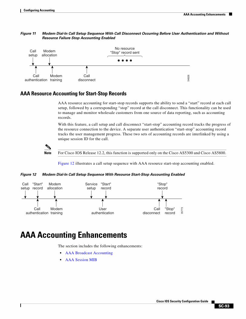
Configuring AccountingAAA Accounting Enhancements
SC-93Cisco IOS Security Configuration Guide
Figure 11 Modem Dial-In Call Setup Sequence With Call Disconnect Occurring Before User Authentication and Without
Resource Failure Stop Accounting Enabled
AAA Resource Accounting for Start-Stop Records
AAA resource accounting for start-stop records supports the ability to send a “start” record at each call setup, followed by a corresponding “stop” record at the call disconnect. This functionality can be used to manage and monitor wholesale customers from one source of data reporting, such as accounting records.
With this feature, a call setup and call disconnect “start-stop” accounting record tracks the progress of the resource connection to the device. A separate user authentication “start-stop” accounting record tracks the user management progress. These two sets of accounting records are interlinked by using a unique session ID for the call.
Note For Cisco IOS Release 12.2, this function is supported only on the Cisco AS5300 and Cisco AS5800.
Figure 12 illustrates a call setup sequence with AAA resource start-stop accounting enabled.
Figure 12 Modem Dial-In Call Setup Sequence With Resource Start-Stop Accounting Enabled
AAA Accounting EnhancementsThe section includes the following enhancements:
• AAA Broadcast Accounting
• AAA Session MIB
Callsetup
Modemallocation
Callauthentication
Modemtraining
Calldisconnect
No resource"Stop" record sent
5482
6
• • • •
Callsetup
Modemallocation
Servicesetup
"Start"record
"Start"record
Callauthentication
Modemtraining
Userauthentication
Calldisconnect
"Stop"record
"Stop"record
3577
3
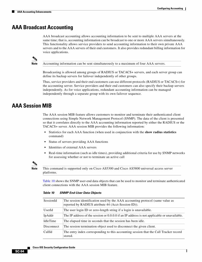
Configuring AccountingAAA Accounting Enhancements
SC-94Cisco IOS Security Configuration Guide
AAA Broadcast Accounting AAA broadcast accounting allows accounting information to be sent to multiple AAA servers at the same time; that is, accounting information can be broadcast to one or more AAA servers simultaneously. This functionality allows service providers to send accounting information to their own private AAA servers and to the AAA servers of their end customers. It also provides redundant billing information for voice applications.
Note Accounting information can be sent simultaneously to a maximum of four AAA servers.
Broadcasting is allowed among groups of RADIUS or TACACS+ servers, and each server group can define its backup servers for failover independently of other groups.
Thus, service providers and their end customers can use different protocols (RADIUS or TACACS+) for the accounting server. Service providers and their end customers can also specify their backup servers independently. As for voice applications, redundant accounting information can be managed independently through a separate group with its own failover sequence.
AAA Session MIB The AAA session MIB feature allows customers to monitor and terminate their authenticated client connections using Simple Network Management Protocol (SNMP). The data of the client is presented so that it correlates directly to the AAA accounting information reported by either the RADIUS or the TACACS+ server. AAA session MIB provides the following information:
• Statistics for each AAA function (when used in conjunction with the show radius statistics command)
• Status of servers providing AAA functions
• Identities of external AAA servers
• Real-time information (such as idle times), providing additional criteria for use by SNMP networks for assessing whether or not to terminate an active call
Note This command is supported only on Cisco AS5300 and Cisco AS5800 universal access server platforms.
Table 10 shows the SNMP user-end data objects that can be used to monitor and terminate authenticated client connections with the AAA session MIB feature.
Table 10 SNMP End-User Data Objects
SessionId The session identification used by the AAA accounting protocol (same value as reported by RADIUS attribute 44 (Acct-Session-ID)).
UserId The user login ID or zero-length string if a login is unavailable.
IpAddr The IP address of the session or 0.0.0.0 if an IP address is not applicable or unavailable.
IdleTime The elapsed time in seconds that the session has been idle.
Disconnect The session termination object used to disconnect the given client.
CallId The entry index corresponding to this accounting session that the Call Tracker record stored.
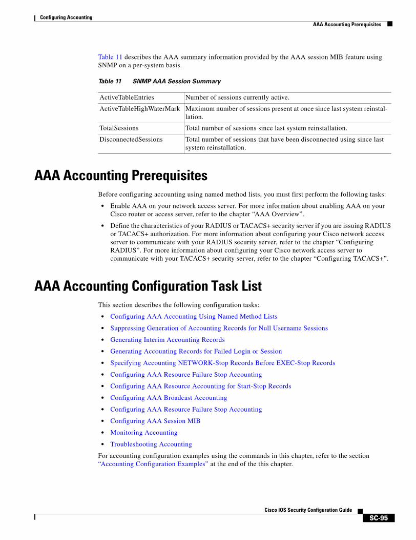
Configuring AccountingAAA Accounting Prerequisites
SC-95Cisco IOS Security Configuration Guide
Table 11 describes the AAA summary information provided by the AAA session MIB feature using SNMP on a per-system basis.
AAA Accounting PrerequisitesBefore configuring accounting using named method lists, you must first perform the following tasks:
• Enable AAA on your network access server. For more information about enabling AAA on your Cisco router or access server, refer to the chapter “AAA Overview”.
• Define the characteristics of your RADIUS or TACACS+ security server if you are issuing RADIUS or TACACS+ authorization. For more information about configuring your Cisco network access server to communicate with your RADIUS security server, refer to the chapter “Configuring RADIUS”. For more information about configuring your Cisco network access server to communicate with your TACACS+ security server, refer to the chapter “Configuring TACACS+”.
AAA Accounting Configuration Task ListThis section describes the following configuration tasks:
• Configuring AAA Accounting Using Named Method Lists
• Suppressing Generation of Accounting Records for Null Username Sessions
• Generating Interim Accounting Records
• Generating Accounting Records for Failed Login or Session
• Specifying Accounting NETWORK-Stop Records Before EXEC-Stop Records
• Configuring AAA Resource Failure Stop Accounting
• Configuring AAA Resource Accounting for Start-Stop Records
• Configuring AAA Broadcast Accounting
• Configuring AAA Resource Failure Stop Accounting
• Configuring AAA Session MIB
• Monitoring Accounting
• Troubleshooting Accounting
For accounting configuration examples using the commands in this chapter, refer to the section “Accounting Configuration Examples” at the end of the this chapter.
Table 11 SNMP AAA Session Summary
ActiveTableEntries Number of sessions currently active.
ActiveTableHighWaterMark Maximum number of sessions present at once since last system reinstal-lation.
TotalSessions Total number of sessions since last system reinstallation.
DisconnectedSessions Total number of sessions that have been disconnected using since last system reinstallation.
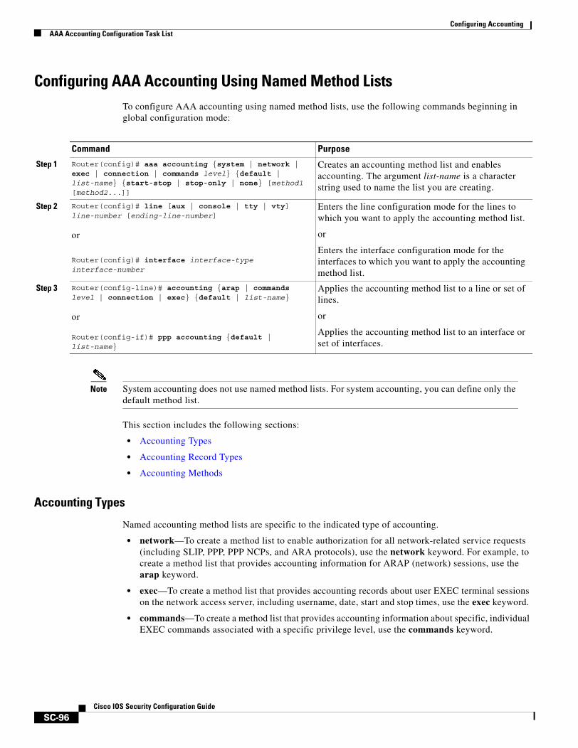
Configuring AccountingAAA Accounting Configuration Task List
SC-96Cisco IOS Security Configuration Guide
Configuring AAA Accounting Using Named Method ListsTo configure AAA accounting using named method lists, use the following commands beginning in global configuration mode:
Note System accounting does not use named method lists. For system accounting, you can define only the default method list.
This section includes the following sections:
• Accounting Types
• Accounting Record Types
• Accounting Methods
Accounting Types
Named accounting method lists are specific to the indicated type of accounting.
• network—To create a method list to enable authorization for all network-related service requests (including SLIP, PPP, PPP NCPs, and ARA protocols), use the network keyword. For example, to create a method list that provides accounting information for ARAP (network) sessions, use the arap keyword.
• exec—To create a method list that provides accounting records about user EXEC terminal sessions on the network access server, including username, date, start and stop times, use the exec keyword.
• commands—To create a method list that provides accounting information about specific, individual EXEC commands associated with a specific privilege level, use the commands keyword.
Command Purpose
Step 1 Router(config)# aaa accounting {system | network | exec | connection | commands level} {default | list-name} {start-stop | stop-only | none} [method1 [method2...]]
Creates an accounting method list and enables accounting. The argument list-name is a character string used to name the list you are creating.
Step 2 Router(config)# line [aux | console | tty | vty] line-number [ending-line-number]
or
Router(config)# interface interface-type interface-number
Enters the line configuration mode for the lines to which you want to apply the accounting method list.
or
Enters the interface configuration mode for the interfaces to which you want to apply the accounting method list.
Step 3 Router(config-line)# accounting {arap | commands level | connection | exec} {default | list-name}
or
Router(config-if)# ppp accounting {default | list-name}
Applies the accounting method list to a line or set of lines.
or
Applies the accounting method list to an interface or set of interfaces.

Configuring AccountingAAA Accounting Configuration Task List
SC-97Cisco IOS Security Configuration Guide
• connection—To create a method list that provides accounting information about all outbound connections made from the network access server, use the connection keyword.
• resource—Creates a method list to provide accounting records for calls that have passed user authentication or calls that failed to be authenticated.
Note System accounting does not support named method lists.
Accounting Record Types
For minimal accounting, use the stop-only keyword, which instructs the specified method (RADIUS or TACACS+) to send a stop record accounting notice at the end of the requested user process. For more accounting information, use the start-stop keyword to send a start accounting notice at the beginning of the requested event and a stop accounting notice at the end of the event. To stop all accounting activities on this line or interface, use the none keyword.
Accounting Methods
Table 12 lists the supported accounting methods.
The method argument refers to the actual method the authentication algorithm tries. Additional methods of authentication are used only if the previous method returns an error, not if it fails. To specify that the authentication should succeed even if all other methods return an error, specify additional methods in the command. For example, to create a method list named acct_tac1 that specifies RADIUS as the backup method of authentication in the event that TACACS+ authentication returns an error, enter the following command:
aaa accounting network acct_tac1 stop-only group tacacs+ group radius
To create a default list that is used when a named list is not specified in the aaa accounting command, use the default keyword followed by the methods you want used in default situations. The default method list is automatically applied to all interfaces.
For example, to specify RADIUS as the default method for user authentication during login, enter the following command:
aaa accounting network default stop-only group radius
Table 12 AAA Accounting Methods
Keyword Description
group radius Uses the list of all RADIUS servers for accounting.
group tacacs+ Uses the list of all TACACS+ servers for accounting.
group group-name Uses a subset of RADIUS or TACACS+ servers for accounting as defined by the server group group-name.
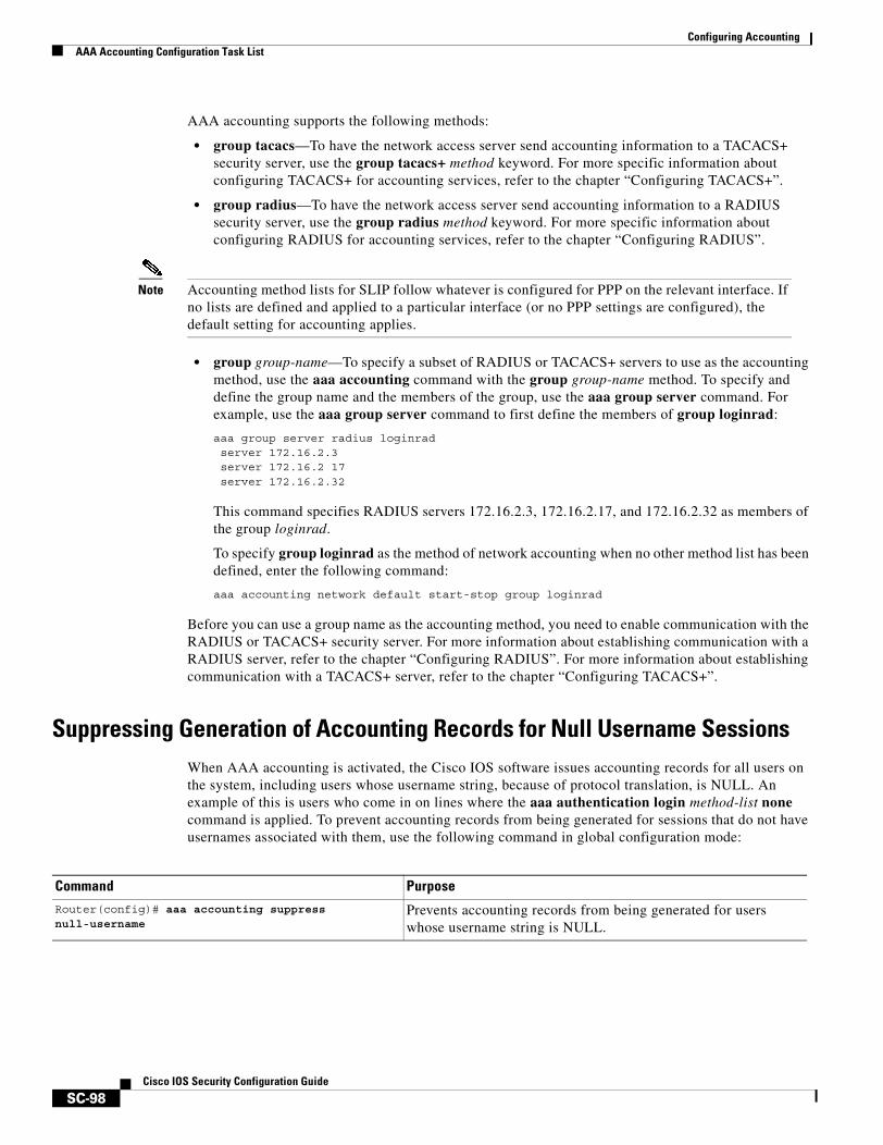
Configuring AccountingAAA Accounting Configuration Task List
SC-98Cisco IOS Security Configuration Guide
AAA accounting supports the following methods:
• group tacacs—To have the network access server send accounting information to a TACACS+ security server, use the group tacacs+ method keyword. For more specific information about configuring TACACS+ for accounting services, refer to the chapter “Configuring TACACS+”.
• group radius—To have the network access server send accounting information to a RADIUS security server, use the group radius method keyword. For more specific information about configuring RADIUS for accounting services, refer to the chapter “Configuring RADIUS”.
Note Accounting method lists for SLIP follow whatever is configured for PPP on the relevant interface. If no lists are defined and applied to a particular interface (or no PPP settings are configured), the default setting for accounting applies.
• group group-name—To specify a subset of RADIUS or TACACS+ servers to use as the accounting method, use the aaa accounting command with the group group-name method. To specify and define the group name and the members of the group, use the aaa group server command. For example, use the aaa group server command to first define the members of group loginrad:
aaa group server radius loginradserver 172.16.2.3server 172.16.2 17server 172.16.2.32
This command specifies RADIUS servers 172.16.2.3, 172.16.2.17, and 172.16.2.32 as members of the group loginrad.
To specify group loginrad as the method of network accounting when no other method list has been defined, enter the following command:
aaa accounting network default start-stop group loginrad
Before you can use a group name as the accounting method, you need to enable communication with the RADIUS or TACACS+ security server. For more information about establishing communication with a RADIUS server, refer to the chapter “Configuring RADIUS”. For more information about establishing communication with a TACACS+ server, refer to the chapter “Configuring TACACS+”.
Suppressing Generation of Accounting Records for Null Username SessionsWhen AAA accounting is activated, the Cisco IOS software issues accounting records for all users on the system, including users whose username string, because of protocol translation, is NULL. An example of this is users who come in on lines where the aaa authentication login method-list none command is applied. To prevent accounting records from being generated for sessions that do not have usernames associated with them, use the following command in global configuration mode:
Command PurposeRouter(config)# aaa accounting suppress null-username
Prevents accounting records from being generated for users whose username string is NULL.
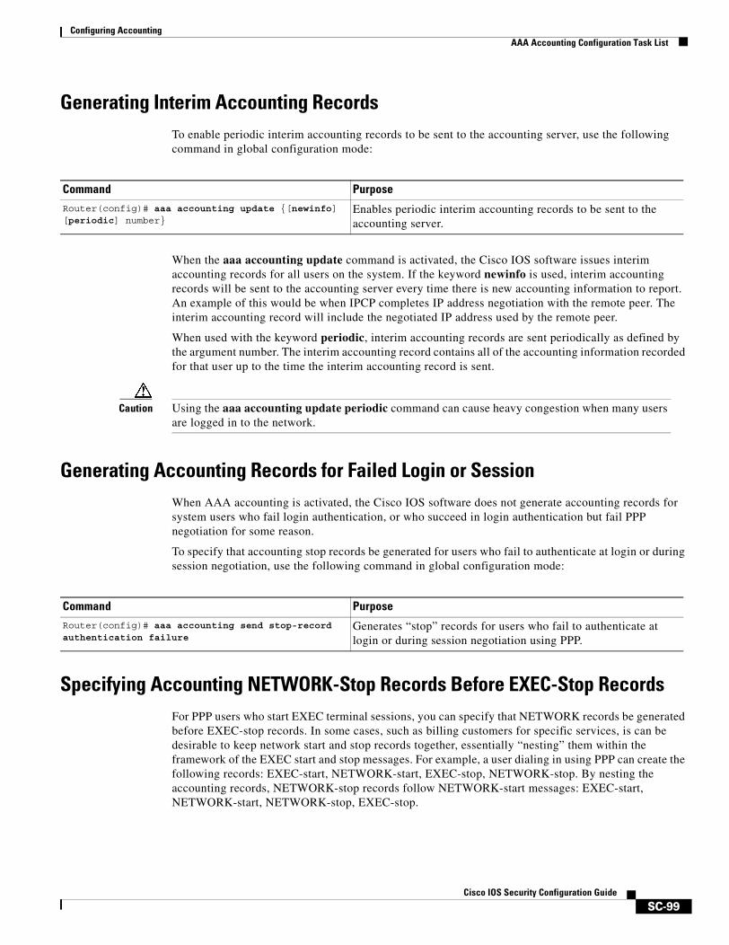
Configuring AccountingAAA Accounting Configuration Task List
SC-99Cisco IOS Security Configuration Guide
Generating Interim Accounting RecordsTo enable periodic interim accounting records to be sent to the accounting server, use the following command in global configuration mode:
When the aaa accounting update command is activated, the Cisco IOS software issues interim accounting records for all users on the system. If the keyword newinfo is used, interim accounting records will be sent to the accounting server every time there is new accounting information to report. An example of this would be when IPCP completes IP address negotiation with the remote peer. The interim accounting record will include the negotiated IP address used by the remote peer.
When used with the keyword periodic, interim accounting records are sent periodically as defined by the argument number. The interim accounting record contains all of the accounting information recorded for that user up to the time the interim accounting record is sent.
Caution Using the aaa accounting update periodic command can cause heavy congestion when many users are logged in to the network.
Generating Accounting Records for Failed Login or SessionWhen AAA accounting is activated, the Cisco IOS software does not generate accounting records for system users who fail login authentication, or who succeed in login authentication but fail PPP negotiation for some reason.
To specify that accounting stop records be generated for users who fail to authenticate at login or during session negotiation, use the following command in global configuration mode:
Specifying Accounting NETWORK-Stop Records Before EXEC-Stop RecordsFor PPP users who start EXEC terminal sessions, you can specify that NETWORK records be generated before EXEC-stop records. In some cases, such as billing customers for specific services, is can be desirable to keep network start and stop records together, essentially “nesting” them within the framework of the EXEC start and stop messages. For example, a user dialing in using PPP can create the following records: EXEC-start, NETWORK-start, EXEC-stop, NETWORK-stop. By nesting the accounting records, NETWORK-stop records follow NETWORK-start messages: EXEC-start, NETWORK-start, NETWORK-stop, EXEC-stop.
Command Purpose
Router(config)# aaa accounting update {[newinfo] [periodic] number}
Enables periodic interim accounting records to be sent to the accounting server.
Command PurposeRouter(config)# aaa accounting send stop-record authentication failure
Generates “stop” records for users who fail to authenticate at login or during session negotiation using PPP.
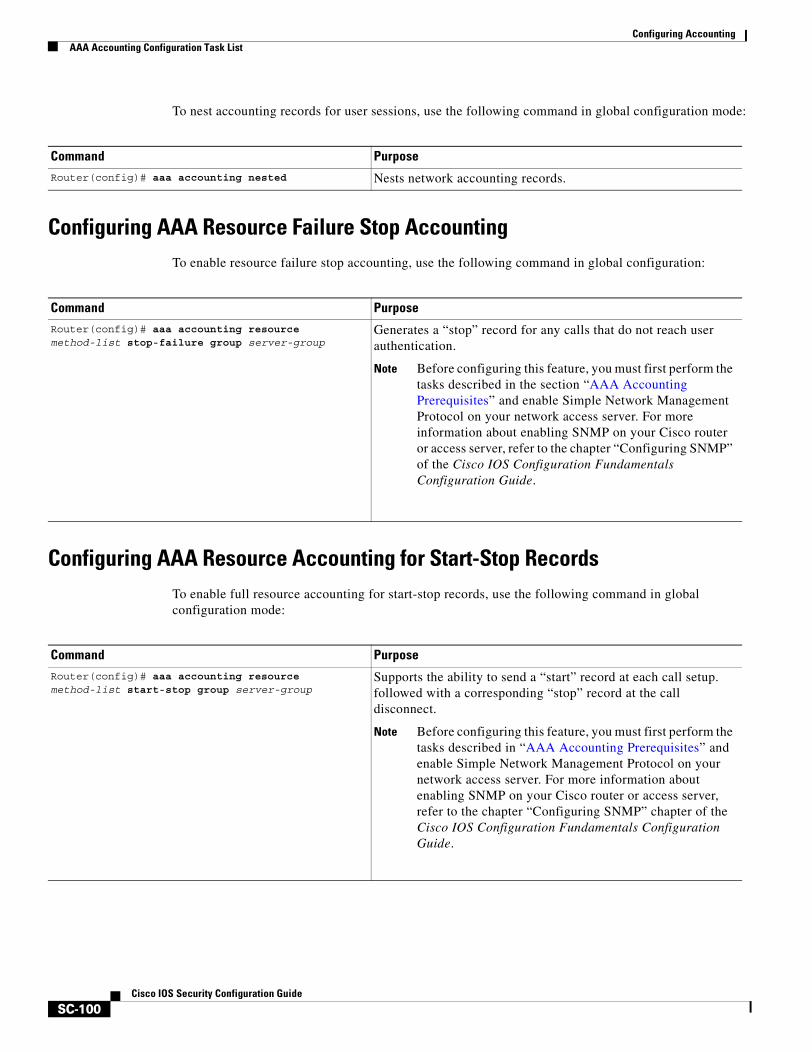
Configuring AccountingAAA Accounting Configuration Task List
SC-100Cisco IOS Security Configuration Guide
To nest accounting records for user sessions, use the following command in global configuration mode:
Configuring AAA Resource Failure Stop AccountingTo enable resource failure stop accounting, use the following command in global configuration:
Configuring AAA Resource Accounting for Start-Stop RecordsTo enable full resource accounting for start-stop records, use the following command in global configuration mode:
Command PurposeRouter(config)# aaa accounting nested Nests network accounting records.
Command PurposeRouter(config)# aaa accounting resource method-list stop-failure group server-group
Generates a “stop” record for any calls that do not reach user authentication.
Note Before configuring this feature, you must first perform the tasks described in the section “AAA Accounting Prerequisites” and enable Simple Network Management Protocol on your network access server. For more information about enabling SNMP on your Cisco router or access server, refer to the chapter “Configuring SNMP” of the Cisco IOS Configuration Fundamentals Configuration Guide.
Command PurposeRouter(config)# aaa accounting resource method-list start-stop group server-group
Supports the ability to send a “start” record at each call setup. followed with a corresponding “stop” record at the call disconnect.
Note Before configuring this feature, you must first perform the tasks described in “AAA Accounting Prerequisites” and enable Simple Network Management Protocol on your network access server. For more information about enabling SNMP on your Cisco router or access server, refer to the chapter “Configuring SNMP” chapter of the Cisco IOS Configuration Fundamentals Configuration Guide.
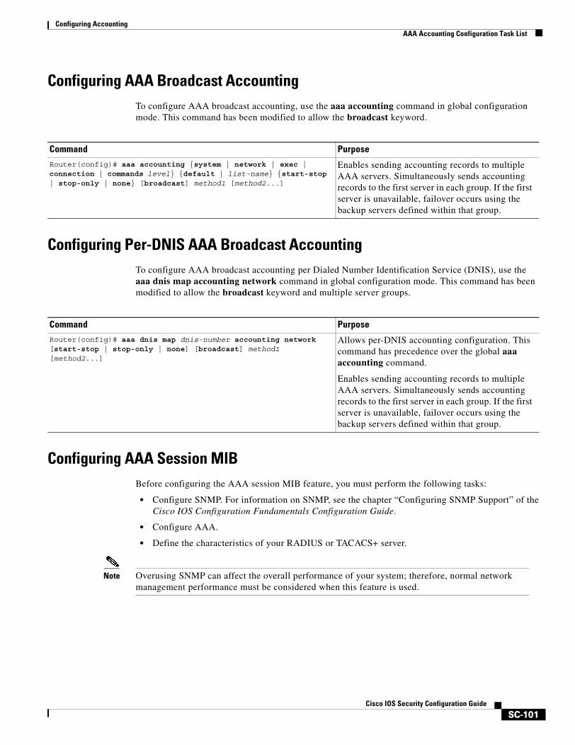
Configuring AccountingAAA Accounting Configuration Task List
SC-101Cisco IOS Security Configuration Guide
Configuring AAA Broadcast AccountingTo configure AAA broadcast accounting, use the aaa accounting command in global configuration mode. This command has been modified to allow the broadcast keyword.
Configuring Per-DNIS AAA Broadcast Accounting To configure AAA broadcast accounting per Dialed Number Identification Service (DNIS), use the aaa dnis map accounting network command in global configuration mode. This command has been modified to allow the broadcast keyword and multiple server groups.
Configuring AAA Session MIBBefore configuring the AAA session MIB feature, you must perform the following tasks:
• Configure SNMP. For information on SNMP, see the chapter “Configuring SNMP Support” of the Cisco IOS Configuration Fundamentals Configuration Guide.
• Configure AAA.
• Define the characteristics of your RADIUS or TACACS+ server.
Note Overusing SNMP can affect the overall performance of your system; therefore, normal network management performance must be considered when this feature is used.
Command Purpose
Router(config)# aaa accounting {system | network | exec | connection | commands level} {default | list-name} {start-stop | stop-only | none} [broadcast] method1 [method2...]
Enables sending accounting records to multiple AAA servers. Simultaneously sends accounting records to the first server in each group. If the first server is unavailable, failover occurs using the backup servers defined within that group.
Command PurposeRouter(config)# aaa dnis map dnis-number accounting network [start-stop | stop-only | none] [broadcast] method1 [method2...]
Allows per-DNIS accounting configuration. This command has precedence over the global aaa accounting command.
Enables sending accounting records to multiple AAA servers. Simultaneously sends accounting records to the first server in each group. If the first server is unavailable, failover occurs using the backup servers defined within that group.
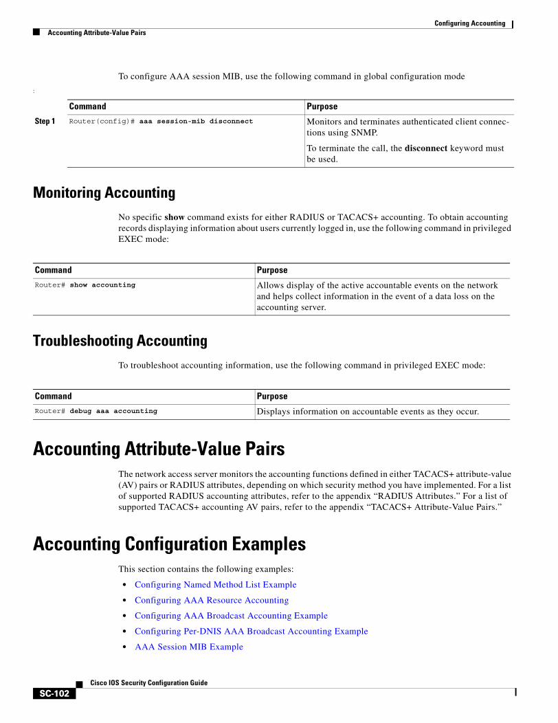
Configuring AccountingAccounting Attribute-Value Pairs
SC-102Cisco IOS Security Configuration Guide
To configure AAA session MIB, use the following command in global configuration mode
:
Monitoring AccountingNo specific show command exists for either RADIUS or TACACS+ accounting. To obtain accounting records displaying information about users currently logged in, use the following command in privileged EXEC mode:
Troubleshooting Accounting To troubleshoot accounting information, use the following command in privileged EXEC mode:
Accounting Attribute-Value PairsThe network access server monitors the accounting functions defined in either TACACS+ attribute-value (AV) pairs or RADIUS attributes, depending on which security method you have implemented. For a list of supported RADIUS accounting attributes, refer to the appendix “RADIUS Attributes.” For a list of supported TACACS+ accounting AV pairs, refer to the appendix “TACACS+ Attribute-Value Pairs.”
Accounting Configuration ExamplesThis section contains the following examples:
• Configuring Named Method List Example
• Configuring AAA Resource Accounting
• Configuring AAA Broadcast Accounting Example
• Configuring Per-DNIS AAA Broadcast Accounting Example
• AAA Session MIB Example
Command Purpose
Step 1 Router(config)# aaa session-mib disconnect Monitors and terminates authenticated client connec-tions using SNMP.
To terminate the call, the disconnect keyword must be used.
Command Purpose
Router# show accounting Allows display of the active accountable events on the network and helps collect information in the event of a data loss on the accounting server.
Command Purpose
Router# debug aaa accounting Displays information on accountable events as they occur.
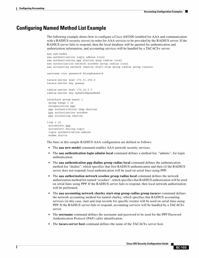
Configuring AccountingAccounting Configuration Examples
SC-103Cisco IOS Security Configuration Guide
Configuring Named Method List ExampleThe following example shows how to configure a Cisco AS5200 (enabled for AAA and communication with a RADIUS security server) in order for AAA services to be provided by the RADIUS server. If the RADIUS server fails to respond, then the local database will be queried for authentication and authorization information, and accounting services will be handled by a TACACS+ server.
aaa new-modelaaa authentication login admins localaaa authentication ppp dialins goup radius localaaa authorization network scoobee group radius localaaa accounting network charley start-stop group radius group tacacs+
username root password ALongPassword
tacacs-server host 172.31.255.0tacacs-server key goaway
radius-server host 172.16.2.7radius-server key myRaDiUSpassWoRd
interface group-async 1group-range 1 16encapsulation pppppp authentication chap dialinsppp authorization scoobeeppp accounting charley
line 1 16autoselect pppautoselect during-loginlogin authentication adminsmodem dialin
The lines in this sample RADIUS AAA configuration are defined as follows:
• The aaa new-model command enables AAA network security services.
• The aaa authentication login admins local command defines a method list, “admins”, for login authentication.
• The aaa authentication ppp dialins group radius local command defines the authentication method list “dialins”, which specifies that first RADIUS authentication and then (if the RADIUS server does not respond) local authentication will be used on serial lines using PPP.
• The aaa authorization network scoobee group radius local command defines the network authorization method list named “scoobee”, which specifies that RADIUS authorization will be used on serial lines using PPP. If the RADIUS server fails to respond, then local network authorization will be performed.
• The aaa accounting network charley start-stop group radius group tacacs+ command defines the network accounting method list named charley, which specifies that RADIUS accounting services (in this case, start and stop records for specific events) will be used on serial lines using PPP. If the RADIUS server fails to respond, accounting services will be handled by a TACACS+ server.
• The username command defines the username and password to be used for the PPP Password Authentication Protocol (PAP) caller identification.
• The tacacs-server host command defines the name of the TACACS+ server host.
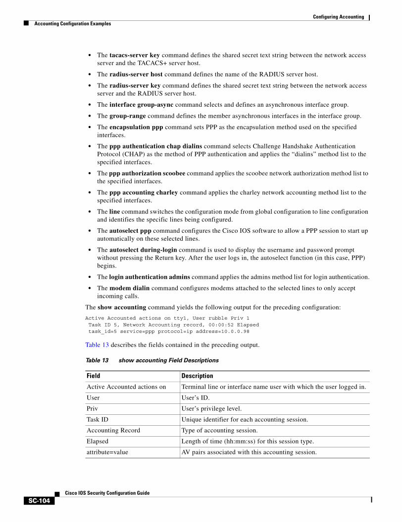
Configuring AccountingAccounting Configuration Examples
SC-104Cisco IOS Security Configuration Guide
• The tacacs-server key command defines the shared secret text string between the network access server and the TACACS+ server host.
• The radius-server host command defines the name of the RADIUS server host.
• The radius-server key command defines the shared secret text string between the network access server and the RADIUS server host.
• The interface group-async command selects and defines an asynchronous interface group.
• The group-range command defines the member asynchronous interfaces in the interface group.
• The encapsulation ppp command sets PPP as the encapsulation method used on the specified interfaces.
• The ppp authentication chap dialins command selects Challenge Handshake Authentication Protocol (CHAP) as the method of PPP authentication and applies the “dialins” method list to the specified interfaces.
• The ppp authorization scoobee command applies the scoobee network authorization method list to the specified interfaces.
• The ppp accounting charley command applies the charley network accounting method list to the specified interfaces.
• The line command switches the configuration mode from global configuration to line configuration and identifies the specific lines being configured.
• The autoselect ppp command configures the Cisco IOS software to allow a PPP session to start up automatically on these selected lines.
• The autoselect during-login command is used to display the username and password prompt without pressing the Return key. After the user logs in, the autoselect function (in this case, PPP) begins.
• The login authentication admins command applies the admins method list for login authentication.
• The modem dialin command configures modems attached to the selected lines to only accept incoming calls.
The show accounting command yields the following output for the preceding configuration:
Active Accounted actions on tty1, User rubble Priv 1 Task ID 5, Network Accounting record, 00:00:52 Elapsed task_id=5 service=ppp protocol=ip address=10.0.0.98
Table 13 describes the fields contained in the preceding output.
Table 13 show accounting Field Descriptions
Field Description
Active Accounted actions on Terminal line or interface name user with which the user logged in.
User User’s ID.
Priv User’s privilege level.
Task ID Unique identifier for each accounting session.
Accounting Record Type of accounting session.
Elapsed Length of time (hh:mm:ss) for this session type.
attribute=value AV pairs associated with this accounting session.
Configuring AccountingAccounting Configuration Examples
SC-105Cisco IOS Security Configuration Guide
Configuring AAA Resource Accounting The following example shows how to configure the resource failure stop accounting and resource accounting for start-stop records functions:
!Enable AAA on your network access server.aaa new-model!Enable authentication at login and list the AOL string name to use for login authentication.aaa authentication login AOL group radius local!Enable authentication for ppp and list the default method to use for PPP authentication.aaa authentication ppp default group radius local!Enable authorization for all exec sessions and list the AOL string name to use for authorization.aaa authorization exec AOL group radius if-authenticated!Enable authorization for all network-related service requests and list the default method to use for all network-related authorizations.aaa authorization network default group radius if-authenticated!Enable accounting for all exec sessions and list the default method to use for all start-stop accounting services.aaa accounting exec default start-stop group radius!Enable accounting for all network-related service requests and list the default method to use for all start-stop accounting services. aaa accounting network default start-stop group radius!Enable failure stop accounting.aaa accounting resource default stop-failure group radius!Enable resource accounting for start-stop records.aaa accounting resource default start-stop group radius
Configuring AAA Broadcast Accounting ExampleThe following example shows how to turn on broadcast accounting using the global aaa accounting command:
aaa group server radius ispserver 1.0.0.1server 1.0.0.2
aaa group server tacacs+ isp_customerserver 3.0.0.1
aaa accounting network default start-stop broadcast group isp group isp_customer
radius-server host 1.0.0.1radius-server host 1.0.0.2radius-server key key1tacacs-server host 3.0.0.1 key key2
The broadcast keyword causes “start” and “stop” accounting records for network connections to be sent simultaneously to server 1.0.0.1 in the group isp and to server 3.0.0.1 in the group isp_customer. If server 1.0.0.1 is unavailable, failover to server 1.0.0.2 occurs. If server 3.0.0.1 is unavailable, no failover occurs because backup servers are not configured for the group isp_customer.
Configuring AccountingAccounting Configuration Examples
SC-106Cisco IOS Security Configuration Guide
Configuring Per-DNIS AAA Broadcast Accounting ExampleThe following example shows how to turn on per DNIS broadcast accounting using the global aaa dnis map accounting network command:
aaa group server radius ispserver 1.0.0.1server 1.0.0.2
aaa group server tacacs+ isp_customerserver 3.0.0.1
aaa dnis map enableaaa dnis map 7777 accounting network start-stop broadcast group isp group isp_customer
radius-server host 1.0.0.1radius-server host 1.0.0.2radius-server key key_1tacacs-server host 3.0.0.1 key key_2
The broadcast keyword causes “start” and “stop” accounting records for network connection calls having DNIS number 7777 to be sent simultaneously to server 1.0.0.1 in the group isp and to server 3.0.0.1 in the group isp_customer. If server 1.0.0.1 is unavailable, failover to server 1.0.0.2 occurs. If server 3.0.0.1 is unavailable, no failover occurs because backup servers are not configured for the group isp_customer.
AAA Session MIB Example The following example shows how to set up the AAA session MIB feature to disconnect authenticated client connections for PPP users:
aaa new-model aaa authentication ppp default group radiusaaa authorization network default group radiusaaa accounting network default start-stop group radiusaaa session-mib disconnect

Security Server Protocols

SC-109Cisco IOS Security Configuration Guide
Configuring RADIUS
This chapter describes the Remote Authentication Dial-In User Service (RADIUS) security system, defines its operation, and identifies appropriate and inappropriate network environments for using RADIUS technology. The “RADIUS Configuration Task List” section describes how to configure RADIUS with the authentication, authorization, and accounting (AAA) command set.
For a complete description of the RADIUS commands used in this chapter, refer to the chapter “RADIUS Commands” in the Cisco IOS Security Command Reference. To locate documentation of other commands that appear in this chapter, use the command reference master index or search online.
To identify the hardware platform or software image information associated with a feature, use the Feature Navigator on Cisco.com to search for information about the feature or refer to the software release notes for a specific release. For more information, see the “Identifying Supported Platforms” section in the “Using Cisco IOS Software” chapter.
In This ChapterThis chapter includes the following sections:
• About RADIUS
• RADIUS Operation
• RADIUS Configuration Task List
• Monitoring and Maintaining RADIUS
• RADIUS Attributes
• RADIUS Configuration Examples
About RADIUSRADIUS is a distributed client/server system that secures networks against unauthorized access. In the Cisco implementation, RADIUS clients run on Cisco routers and send authentication requests to a central RADIUS server that contains all user authentication and network service access information.
RADIUS is a fully open protocol, distributed in source code format, that can be modified to work with any security system currently available on the market.
Cisco supports RADIUS under its AAA security paradigm. RADIUS can be used with other AAA security protocols, such as TACACS+, Kerberos, and local username lookup. RADIUS is supported on all Cisco platforms, but some RADIUS-supported features run only on specified platforms.
Configuring RADIUSRADIUS Operation
SC-110Cisco IOS Security Configuration Guide
RADIUS has been implemented in a variety of network environments that require high levels of security while maintaining network access for remote users.
Use RADIUS in the following network environments that require access security:
• Networks with multiple-vendor access servers, each supporting RADIUS. For example, access servers from several vendors use a single RADIUS server-based security database. In an IP-based network with multiple vendors’ access servers, dial-in users are authenticated through a RADIUS server that has been customized to work with the Kerberos security system.
• Turnkey network security environments in which applications support the RADIUS protocol, such as in an access environment that uses a “smart card” access control system. In one case, RADIUS has been used with Enigma’s security cards to validate users and grant access to network resources.
• Networks already using RADIUS. You can add a Cisco router with RADIUS to the network. This might be the first step when you make a transition to a Terminal Access Controller Access Control System Plus (TACACS+) server.
• Networks in which a user must only access a single service. Using RADIUS, you can control user access to a single host, to a single utility such as Telnet, or to a single protocol such as Point-to-Point Protocol (PPP). For example, when a user logs in, RADIUS identifies this user as having authorization to run PPP using IP address 10.2.3.4 and the defined access list is started.
• Networks that require resource accounting. You can use RADIUS accounting independent of RADIUS authentication or authorization. The RADIUS accounting functions allow data to be sent at the start and end of services, indicating the amount of resources (such as time, packets, bytes, and so on) used during the session. An Internet service provider (ISP) might use a freeware-based version of RADIUS access control and accounting software to meet special security and billing needs.
• Networks that wish to support preauthentication. Using the RADIUS server in your network, you can configure AAA preauthentication and set up the preauthentication profiles. Preauthentication enables service providers to better manage ports using their existing RADIUS solutions, and to efficiently manage the use of shared resources to offer differing service-level agreements.
RADIUS is not suitable in the following network security situations:
• Multiprotocol access environments. RADIUS does not support the following protocols:
– AppleTalk Remote Access (ARA)
– NetBIOS Frame Control Protocol (NBFCP)
– NetWare Asynchronous Services Interface (NASI)
– X.25 PAD connections
• Router-to-router situations. RADIUS does not provide two-way authentication. RADIUS can be used to authenticate from one router to a non-Cisco router if the non-Cisco router requires RADIUS authentication.
• Networks using a variety of services. RADIUS generally binds a user to one service model.
RADIUS OperationWhen a user attempts to log in and authenticate to an access server using RADIUS, the following steps occur:
1. The user is prompted for and enters a username and password.
2. The username and encrypted password are sent over the network to the RADIUS server.
Configuring RADIUSRADIUS Configuration Task List
SC-111Cisco IOS Security Configuration Guide
3. The user receives one of the following responses from the RADIUS server:
a. ACCEPT—The user is authenticated.
b. REJECT—The user is not authenticated and is prompted to reenter the username and password, or access is denied.
c. CHALLENGE—A challenge is issued by the RADIUS server. The challenge collects additional data from the user.
d. CHANGE PASSWORD—A request is issued by the RADIUS server, asking the user to select a new password.
The ACCEPT or REJECT response is bundled with additional data that is used for EXEC or network authorization. You must first complete RADIUS authentication before using RADIUS authorization. The additional data included with the ACCEPT or REJECT packets consists of the following:
• Services that the user can access, including Telnet, rlogin, or local-area transport (LAT) connections, and PPP, Serial Line Internet Protocol (SLIP), or EXEC services.
• Connection parameters, including the host or client IP address, access list, and user timeouts.
RADIUS Configuration Task ListTo configure RADIUS on your Cisco router or access server, you must perform the following tasks:
• Use the aaa new-model global configuration command to enable AAA. AAA must be configured if you plan to use RADIUS. For more information about using the aaa new-model command, refer to the “AAA Overview” chapter.
• Use the aaa authentication global configuration command to define method lists for RADIUS authentication. For more information about using the aaa authentication command, refer to the “Configuring Authentication” chapter.
• Use line and interface commands to enable the defined method lists to be used. For more information, refer to the “Configuring Authentication” chapter.
The following configuration tasks are optional:
• You may use the aaa server group command to group selected RADIUS hosts for specific services. For more information about using the aaa server group command, refer to the “Configuring AAA Server Groups” section in this chapter.
• You may use the aaa dnis map command to select RADIUS server groups based on DNIS number. To use this command, you must define RADIUS server groups using the aaa server group command. For more information about using the aaa dnis map command, refer to the section “Configuring AAA Server Group Selection Based on DNIS” in this chapter.
• You may use the aaa authorization global command to authorize specific user functions. For more information about using the aaa authorization command, refer to the chapter “Configuring Authorization.”
• You may use the aaa accounting command to enable accounting for RADIUS connections. For more information about using the aaa accounting command, refer to the chapter “Configuring Accounting.”
• You may use the dialer aaa interface configuration command to create remote site profiles that contain outgoing call attributes on the AAA server. For more information about using the dialer aaa command, refer to the section “Configuring Suffix and Password in RADIUS Access Requests” in this chapter.

Configuring RADIUSRADIUS Configuration Task List
SC-112Cisco IOS Security Configuration Guide
This section describes how to set up RADIUS for authentication, authorization, and accounting on your network, and includes the following sections:
• Configuring Router to RADIUS Server Communication (Required)
• Configuring Router to Use Vendor-Specific RADIUS Attributes (Optional)
• Configuring Router for Vendor-Proprietary RADIUS Server Communication (Optional)
• Configuring Router to Query RADIUS Server for Static Routes and IP Addresses (Optional)
• Configuring Router to Expand Network Access Server Port Information (Optional)
• Configuring AAA Server Groups (Optional)
• Configuring AAA Server Groups with Deadtime (Optional)
• Configuring AAA DNIS Authentication
• Configuring AAA Server Group Selection Based on DNIS (Optional)
• Configuring AAA Preauthentication
• Configuring a Guard Timer
• Specifying RADIUS Authentication
• Specifying RADIUS Authorization (Optional)
• Specifying RADIUS Accounting (Optional)
• Configuring RADIUS Login-IP-Host (Optional)
• Configuring RADIUS Prompt (Optional)
• Configuring Suffix and Password in RADIUS Access Requests (Optional)
For RADIUS configuration examples using the commands in this chapter, refer to the section “RADIUS Configuration Examples” at the end of this chapter.
Configuring Router to RADIUS Server CommunicationThe RADIUS host is normally a multiuser system running RADIUS server software from Cisco (CiscoSecure ACS), Livingston, Merit, Microsoft, or another software provider. Configuring router to RADIUS server communication can have several components:
• Host name or IP address
• Authentication destination port
• Accounting destination port
• Timeout period
• Retransmission value
• Key string
RADIUS security servers are identified on the basis of their host name or IP address, host name and specific UDP port numbers, or IP address and specific UDP port numbers. The combination of the IP address and UDP port number creates a unique identifier, allowing different ports to be individually defined as RADIUS hosts providing a specific AAA service. In other words, this unique identifier enables RADIUS requests to be sent to multiple UDP ports on a server at the same IP address. If two different host entries on the same RADIUS server are configured for the same service—for example, accounting—the second host entry configured acts as fail-over backup to the first one. Using this
Configuring RADIUSRADIUS Configuration Task List
SC-113Cisco IOS Security Configuration Guide
example, if the first host entry fails to provide accounting services, the network access server will try the second host entry configured on the same device for accounting services. (The RADIUS host entries will be tried in the order they are configured.)
A RADIUS server and a Cisco router use a shared secret text string to encrypt passwords and exchange responses.To configure RADIUS to use the AAA security commands, you must specify the host running the RADIUS server daemon and a secret text (key) string that it shares with the router.
The timeout, retransmission, and encryption key values are configurable globally for all RADIUS servers, on a per-server basis, or in some combination of global and per-server settings. To apply these settings globally to all RADIUS servers communicating with the router, use the three unique global commands: radius-server timeout, radius-server retransmit, and radius-server key. To apply these values on a specific RADIUS server, use the radius-server host command.
Note You can configure both global and per-server timeout, retransmission, and key value commands simultaneously on the same Cisco network access server. If both global and per-server functions are configured on a router, the per-server timer, retransmission, and key value commands override global timer, retransmission, and key value commands.
To configure per-server RADIUS server communication, use the following command in global configuration mode:
Command PurposeRouter(config)# radius-server host {hostname | ip-address} [auth-port port-number] [acct-port port-number] [timeout seconds] [retransmit retries] [key string] [alias {hostname | ip address}]
Specifies the IP address or host name of the remote RADIUS server host and assign authentication and accounting destination port numbers. Use the auth-port port-number option to configure a specific UDP port on this RADIUS server to be used solely for authentication. Use the acct-port port-number option to configure a specific UDP port on this RADIUS server to be used solely for accounting. Use the alias keyword to configure up to eight multiple IP addresses for use when referring to RADIUS servers.
To configure the network access server to recognize more than one host entry associated with a single IP address, simply repeat this command as many times as necessary, making sure that each UDP port number is different. Set the timeout, retransmit, and encryption key values to use with the specific RADIUS host.
If no timeout is set, the global value is used; otherwise, enter a value in the range 1 to 1000. If no retransmit value is set, the global value is used; otherwise enter a value in the range 1 to 1000. If no key string is specified, the global value is used.
Note The key is a text string that must match the encryption key used on the RADIUS server. Always configure the key as the last item in the radius-server host command syntax because the leading spaces are ignored, but spaces within and at the end of the key are used. If you use spaces in your key, do not enclose the key in quotation marks unless the quotation marks themselves are part of the key.
Configuring RADIUSRADIUS Configuration Task List
SC-114Cisco IOS Security Configuration Guide
To configure global communication settings between the router and a RADIUS server, use the following radius-server commands in global configuration mode:
Configuring Router to Use Vendor-Specific RADIUS AttributesThe Internet Engineering Task Force (IETF) draft standard specifies a method for communicating vendor-specific information between the network access server and the RADIUS server by using the vendor-specific attribute (attribute 26). Vendor-specific attributes (VSAs) allow vendors to support their own extended attributes not suitable for general use. The Cisco RADIUS implementation supports one vendor-specific option using the format recommended in the specification. Cisco’s vendor-ID is 9, and the supported option has vendor-type 1, which is named “cisco-avpair.” The value is a string of the following format:
protocol : attribute sep value *
“Protocol” is a value of the Cisco “protocol” attribute for a particular type of authorization. “Attribute” and “value” are an appropriate attribute-value (AV) pair defined in the Cisco TACACS+ specification, and “sep” is “=” for mandatory attributes and “*” for optional attributes. This allows the full set of features available for TACACS+ authorization to also be used for RADIUS.
For example, the following AV pair causes Cisco’s “multiple named ip address pools” feature to be activated during IP authorization (during PPP’s IPCP address assignment):
cisco-avpair= ”ip:addr-pool=first“
The following example shows how to cause a user logging in from a network access server to have immediate access to EXEC commands:
cisco-avpair= ”shell:priv-lvl=15“
Other vendors have their own unique vendor-IDs, options, and associated VSAs. For more information about vendor-IDs and VSAs, refer to RFC 2138, Remote Authentication Dial-In User Service (RADIUS).
Command Purpose
Step 1 Router(config)# radius-server key {0 string | 7 string | string}
Specifies the shared secret text string used between the router and a RADIUS server. Use the 0 line option to configure an unencrypted shared secret. Use the 7 line option to configure an encrypted shared secret.
Step 2 Router(config)# radius-server retransmit retries Specifies how many times the router transmits each RADIUS request to the server before giving up (the default is 3).
Step 3 Router(config)# radius-server timeout seconds Specifies for how many seconds a router waits for a reply to a RADIUS request before retransmitting the request.
Step 4 Router(config)# radius-server deadtime minutes Specifies for how many minutes a RADIUS server that is not responding to authentication requests is passed over by requests for RADIUS authentication.
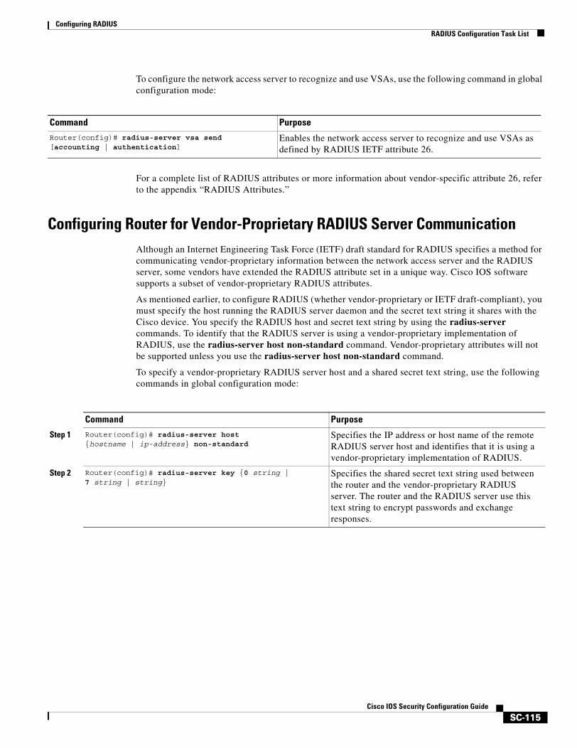
Configuring RADIUSRADIUS Configuration Task List
SC-115Cisco IOS Security Configuration Guide
To configure the network access server to recognize and use VSAs, use the following command in global configuration mode:
For a complete list of RADIUS attributes or more information about vendor-specific attribute 26, refer to the appendix “RADIUS Attributes.”
Configuring Router for Vendor-Proprietary RADIUS Server CommunicationAlthough an Internet Engineering Task Force (IETF) draft standard for RADIUS specifies a method for communicating vendor-proprietary information between the network access server and the RADIUS server, some vendors have extended the RADIUS attribute set in a unique way. Cisco IOS software supports a subset of vendor-proprietary RADIUS attributes.
As mentioned earlier, to configure RADIUS (whether vendor-proprietary or IETF draft-compliant), you must specify the host running the RADIUS server daemon and the secret text string it shares with the Cisco device. You specify the RADIUS host and secret text string by using the radius-server commands. To identify that the RADIUS server is using a vendor-proprietary implementation of RADIUS, use the radius-server host non-standard command. Vendor-proprietary attributes will not be supported unless you use the radius-server host non-standard command.
To specify a vendor-proprietary RADIUS server host and a shared secret text string, use the following commands in global configuration mode:
Command PurposeRouter(config)# radius-server vsa send [accounting | authentication]
Enables the network access server to recognize and use VSAs as defined by RADIUS IETF attribute 26.
Command Purpose
Step 1 Router(config)# radius-server host {hostname | ip-address} non-standard
Specifies the IP address or host name of the remote RADIUS server host and identifies that it is using a vendor-proprietary implementation of RADIUS.
Step 2 Router(config)# radius-server key {0 string | 7 string | string}
Specifies the shared secret text string used between the router and the vendor-proprietary RADIUS server. The router and the RADIUS server use this text string to encrypt passwords and exchange responses.
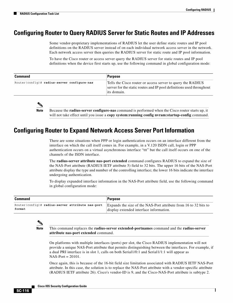
Configuring RADIUSRADIUS Configuration Task List
SC-116Cisco IOS Security Configuration Guide
Configuring Router to Query RADIUS Server for Static Routes and IP AddressesSome vendor-proprietary implementations of RADIUS let the user define static routes and IP pool definitions on the RADIUS server instead of on each individual network access server in the network. Each network access server then queries the RADIUS server for static route and IP pool information.
To have the Cisco router or access server query the RADIUS server for static routes and IP pool definitions when the device first starts up, use the following command in global configuration mode:
Note Because the radius-server configure-nas command is performed when the Cisco router starts up, it will not take effect until you issue a copy system:running config nvram:startup-config command.
Configuring Router to Expand Network Access Server Port InformationThere are some situations when PPP or login authentication occurs on an interface different from the interface on which the call itself comes in. For example, in a V.120 ISDN call, login or PPP authentication occurs on a virtual asynchronous interface “ttt” but the call itself occurs on one of the channels of the ISDN interface.
The radius-server attribute nas-port extended command configures RADIUS to expand the size of the NAS-Port attribute (RADIUS IETF attribute 5) field to 32 bits. The upper 16 bits of the NAS-Port attribute display the type and number of the controlling interface; the lower 16 bits indicate the interface undergoing authentication.
To display expanded interface information in the NAS-Port attribute field, use the following command in global configuration mode:
Note This command replaces the radius-server extended-portnames command and the radius-server attribute nas-port extended command.
On platforms with multiple interfaces (ports) per slot, the Cisco RADIUS implementation will not provide a unique NAS-Port attribute that permits distinguishing between the interfaces. For example, if a dual PRI interface is in slot 1, calls on both Serial1/0:1 and Serial1/1:1 will appear as NAS-Port = 20101.
Once again, this is because of the 16-bit field size limitation associated with RADIUS IETF NAS-Port attribute. In this case, the solution is to replace the NAS-Port attribute with a vendor-specific attribute (RADIUS IETF attribute 26). Cisco's vendor-ID is 9, and the Cisco-NAS-Port attribute is subtype 2.
Command Purpose
Router(config)# radius-server configure-nas Tells the Cisco router or access server to query the RADIUS server for the static routes and IP pool definitions used throughout its domain.
Command PurposeRouter(config)# radius-server attribute nas-port format
Expands the size of the NAS-Port attribute from 16 to 32 bits to display extended interface information.
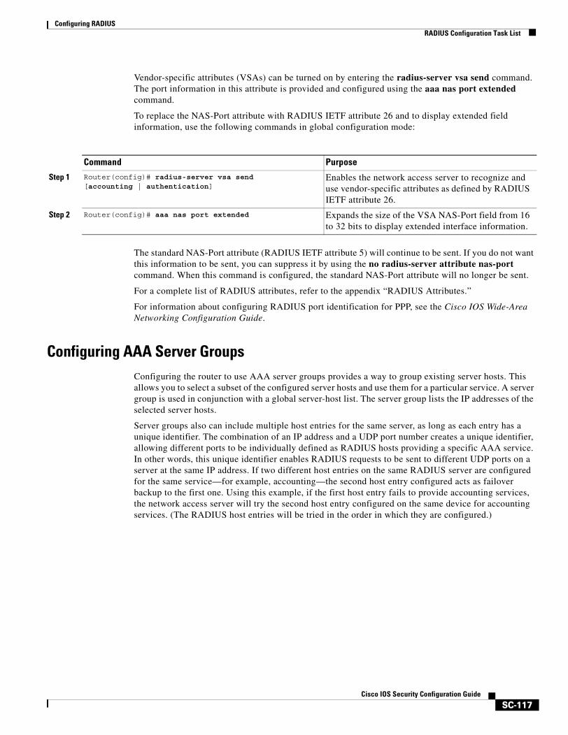
Configuring RADIUSRADIUS Configuration Task List
SC-117Cisco IOS Security Configuration Guide
Vendor-specific attributes (VSAs) can be turned on by entering the radius-server vsa send command. The port information in this attribute is provided and configured using the aaa nas port extended command.
To replace the NAS-Port attribute with RADIUS IETF attribute 26 and to display extended field information, use the following commands in global configuration mode:
The standard NAS-Port attribute (RADIUS IETF attribute 5) will continue to be sent. If you do not want this information to be sent, you can suppress it by using the no radius-server attribute nas-port command. When this command is configured, the standard NAS-Port attribute will no longer be sent.
For a complete list of RADIUS attributes, refer to the appendix “RADIUS Attributes.”
For information about configuring RADIUS port identification for PPP, see the Cisco IOS Wide-Area Networking Configuration Guide.
Configuring AAA Server GroupsConfiguring the router to use AAA server groups provides a way to group existing server hosts. This allows you to select a subset of the configured server hosts and use them for a particular service. A server group is used in conjunction with a global server-host list. The server group lists the IP addresses of the selected server hosts.
Server groups also can include multiple host entries for the same server, as long as each entry has a unique identifier. The combination of an IP address and a UDP port number creates a unique identifier, allowing different ports to be individually defined as RADIUS hosts providing a specific AAA service. In other words, this unique identifier enables RADIUS requests to be sent to different UDP ports on a server at the same IP address. If two different host entries on the same RADIUS server are configured for the same service—for example, accounting—the second host entry configured acts as failover backup to the first one. Using this example, if the first host entry fails to provide accounting services, the network access server will try the second host entry configured on the same device for accounting services. (The RADIUS host entries will be tried in the order in which they are configured.)
Command Purpose
Step 1 Router(config)# radius-server vsa send [accounting | authentication]
Enables the network access server to recognize and use vendor-specific attributes as defined by RADIUS IETF attribute 26.
Step 2 Router(config)# aaa nas port extended Expands the size of the VSA NAS-Port field from 16 to 32 bits to display extended interface information.
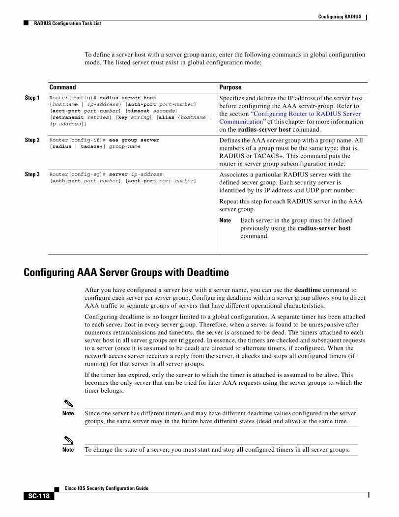
Configuring RADIUSRADIUS Configuration Task List
SC-118Cisco IOS Security Configuration Guide
To define a server host with a server group name, enter the following commands in global configuration mode. The listed server must exist in global configuration mode:
Configuring AAA Server Groups with Deadtime After you have configured a server host with a server name, you can use the deadtime command to configure each server per server group. Configuring deadtime within a server group allows you to direct AAA traffic to separate groups of servers that have different operational characteristics.
Configuring deadtime is no longer limited to a global configuration. A separate timer has been attached to each server host in every server group. Therefore, when a server is found to be unresponsive after numerous retransmissions and timeouts, the server is assumed to be dead. The timers attached to each server host in all server groups are triggered. In essence, the timers are checked and subsequent requests to a server (once it is assumed to be dead) are directed to alternate timers, if configured. When the network access server receives a reply from the server, it checks and stops all configured timers (if running) for that server in all server groups.
If the timer has expired, only the server to which the timer is attached is assumed to be alive. This becomes the only server that can be tried for later AAA requests using the server groups to which the timer belongs.
Note Since one server has different timers and may have different deadtime values configured in the server groups, the same server may in the future have different states (dead and alive) at the same time.
Note To change the state of a server, you must start and stop all configured timers in all server groups.
Command Purpose
Step 1 Router(config)# radius-server host {hostname | ip-address} [auth-port port-number] [acct-port port-number] [timeout seconds] [retransmit retries] [key string] [alias {hostname | ip address}]
Specifies and defines the IP address of the server host before configuring the AAA server-group. Refer to the section “Configuring Router to RADIUS Server Communication” of this chapter for more information on the radius-server host command.
Step 2 Router(config-if)# aaa group server {radius | tacacs+} group-name
Defines the AAA server group with a group name. All members of a group must be the same type; that is, RADIUS or TACACS+. This command puts the router in server group subconfiguration mode.
Step 3 Router(config-sg)# server ip-address [auth-port port-number] [acct-port port-number]
Associates a particular RADIUS server with the defined server group. Each security server is identified by its IP address and UDP port number.
Repeat this step for each RADIUS server in the AAA server group.
Note Each server in the group must be defined previously using the radius-server host command.
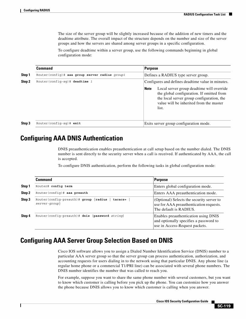
Configuring RADIUSRADIUS Configuration Task List
SC-119Cisco IOS Security Configuration Guide
The size of the server group will be slightly increased because of the addition of new timers and the deadtime attribute. The overall impact of the structure depends on the number and size of the server groups and how the servers are shared among server groups in a specific configuration.
To configure deadtime within a server group, use the following commands beginning in global configuration mode:
Configuring AAA DNIS AuthenticationDNIS preauthentication enables preauthentication at call setup based on the number dialed. The DNIS number is sent directly to the security server when a call is received. If authenticated by AAA, the call is accepted.
To configure DNIS authentication, perform the following tasks in global configuration mode:
Configuring AAA Server Group Selection Based on DNISCisco IOS software allows you to assign a Dialed Number Identification Service (DNIS) number to a particular AAA server group so that the server group can process authentication, authorization, and accounting requests for users dialing in to the network using that particular DNIS. Any phone line (a regular home phone or a commercial T1/PRI line) can be associated with several phone numbers. The DNIS number identifies the number that was called to reach you.
For example, suppose you want to share the same phone number with several customers, but you want to know which customer is calling before you pick up the phone. You can customize how you answer the phone because DNIS allows you to know which customer is calling when you answer.
Command Purpose
Step 1 Router(config)# aaa group server radius group1 Defines a RADIUS type server group.
Step 2 Router(config-sg)# deadtime 1 Configures and defines deadtime value in minutes.
Note Local server group deadtime will override the global configuration. If omitted from the local server group configuration, the value will be inherited from the master list.
Step 3 Router(config-sg)# exit Exits server group configuration mode.
Command Purpose
Step 1 Router# config term Enters global configuration mode.
Step 2 Router(config)# aaa preauth Enters AAA preauthentication mode.
Step 3 Router(config-preauth)# group {radius | tacacs+ | server-group}
(Optional) Selects the security server to use for AAA preauthentication requests. The default is RADIUS.
Step 4 Router(config-preauth)# dnis [password string] Enables preauthentication using DNIS and optionally specifies a password to use in Access-Request packets.
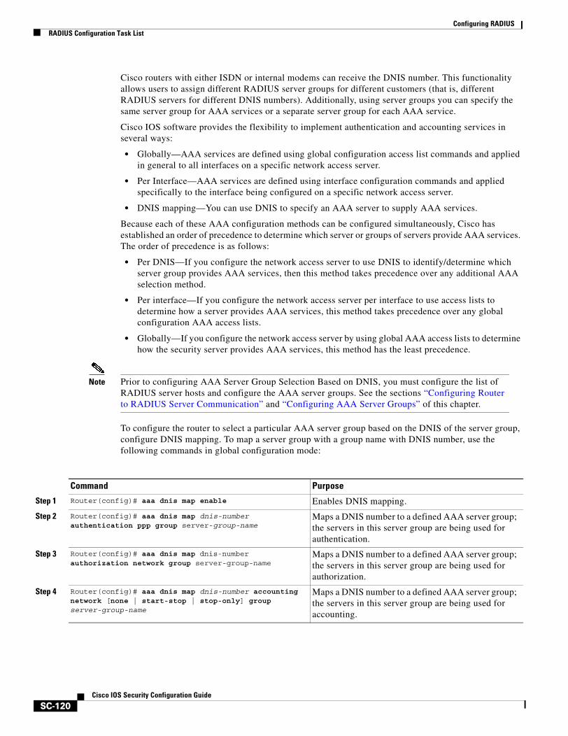
Configuring RADIUSRADIUS Configuration Task List
SC-120Cisco IOS Security Configuration Guide
Cisco routers with either ISDN or internal modems can receive the DNIS number. This functionality allows users to assign different RADIUS server groups for different customers (that is, different RADIUS servers for different DNIS numbers). Additionally, using server groups you can specify the same server group for AAA services or a separate server group for each AAA service.
Cisco IOS software provides the flexibility to implement authentication and accounting services in several ways:
• Globally—AAA services are defined using global configuration access list commands and applied in general to all interfaces on a specific network access server.
• Per Interface—AAA services are defined using interface configuration commands and applied specifically to the interface being configured on a specific network access server.
• DNIS mapping—You can use DNIS to specify an AAA server to supply AAA services.
Because each of these AAA configuration methods can be configured simultaneously, Cisco has established an order of precedence to determine which server or groups of servers provide AAA services. The order of precedence is as follows:
• Per DNIS—If you configure the network access server to use DNIS to identify/determine which server group provides AAA services, then this method takes precedence over any additional AAA selection method.
• Per interface—If you configure the network access server per interface to use access lists to determine how a server provides AAA services, this method takes precedence over any global configuration AAA access lists.
• Globally—If you configure the network access server by using global AAA access lists to determine how the security server provides AAA services, this method has the least precedence.
Note Prior to configuring AAA Server Group Selection Based on DNIS, you must configure the list of RADIUS server hosts and configure the AAA server groups. See the sections “Configuring Router to RADIUS Server Communication” and “Configuring AAA Server Groups” of this chapter.
To configure the router to select a particular AAA server group based on the DNIS of the server group, configure DNIS mapping. To map a server group with a group name with DNIS number, use the following commands in global configuration mode:
Command Purpose
Step 1 Router(config)# aaa dnis map enable Enables DNIS mapping.
Step 2 Router(config)# aaa dnis map dnis-number authentication ppp group server-group-name
Maps a DNIS number to a defined AAA server group; the servers in this server group are being used for authentication.
Step 3 Router(config)# aaa dnis map dnis-number authorization network group server-group-name
Maps a DNIS number to a defined AAA server group; the servers in this server group are being used for authorization.
Step 4 Router(config)# aaa dnis map dnis-number accounting network [none | start-stop | stop-only] group server-group-name
Maps a DNIS number to a defined AAA server group; the servers in this server group are being used for accounting.
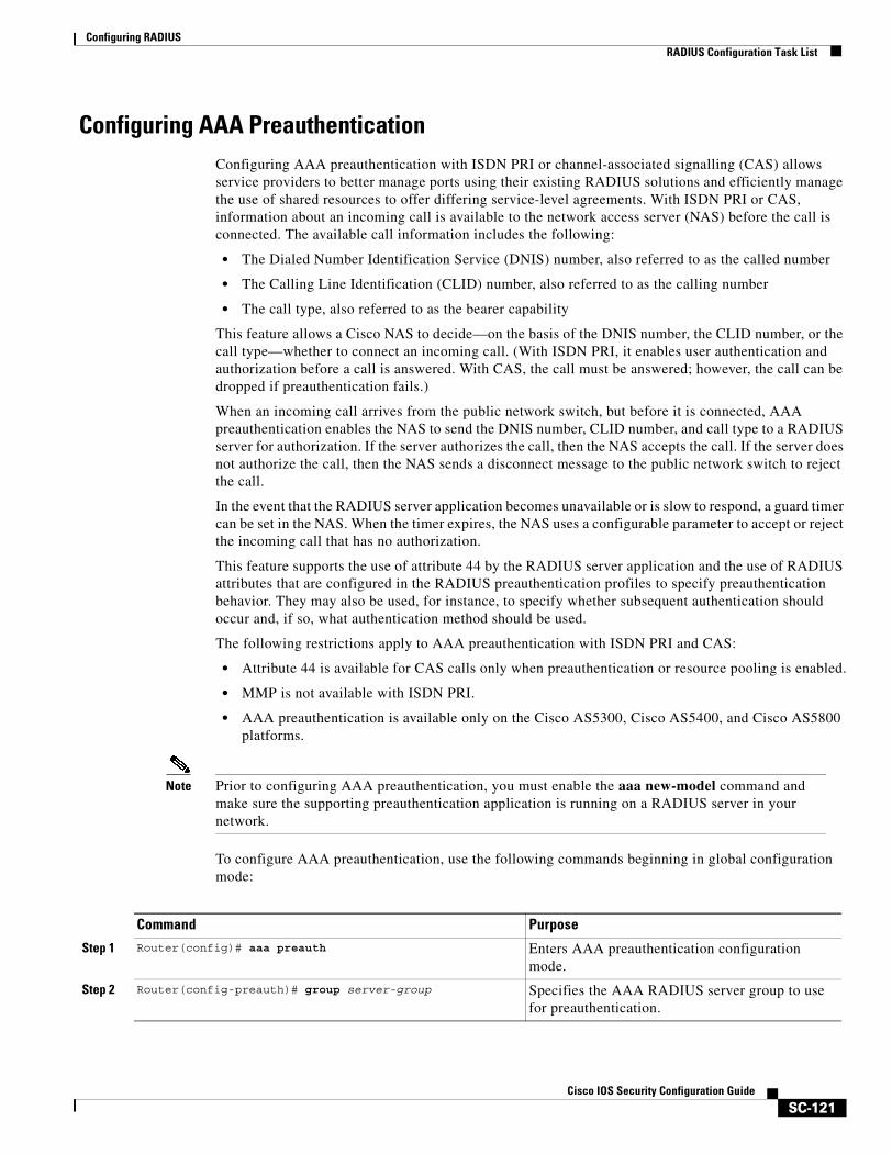
Configuring RADIUSRADIUS Configuration Task List
SC-121Cisco IOS Security Configuration Guide
Configuring AAA Preauthentication Configuring AAA preauthentication with ISDN PRI or channel-associated signalling (CAS) allows service providers to better manage ports using their existing RADIUS solutions and efficiently manage the use of shared resources to offer differing service-level agreements. With ISDN PRI or CAS, information about an incoming call is available to the network access server (NAS) before the call is connected. The available call information includes the following:
• The Dialed Number Identification Service (DNIS) number, also referred to as the called number
• The Calling Line Identification (CLID) number, also referred to as the calling number
• The call type, also referred to as the bearer capability
This feature allows a Cisco NAS to decide—on the basis of the DNIS number, the CLID number, or the call type—whether to connect an incoming call. (With ISDN PRI, it enables user authentication and authorization before a call is answered. With CAS, the call must be answered; however, the call can be dropped if preauthentication fails.)
When an incoming call arrives from the public network switch, but before it is connected, AAA preauthentication enables the NAS to send the DNIS number, CLID number, and call type to a RADIUS server for authorization. If the server authorizes the call, then the NAS accepts the call. If the server does not authorize the call, then the NAS sends a disconnect message to the public network switch to reject the call.
In the event that the RADIUS server application becomes unavailable or is slow to respond, a guard timer can be set in the NAS. When the timer expires, the NAS uses a configurable parameter to accept or reject the incoming call that has no authorization.
This feature supports the use of attribute 44 by the RADIUS server application and the use of RADIUS attributes that are configured in the RADIUS preauthentication profiles to specify preauthentication behavior. They may also be used, for instance, to specify whether subsequent authentication should occur and, if so, what authentication method should be used.
The following restrictions apply to AAA preauthentication with ISDN PRI and CAS:
• Attribute 44 is available for CAS calls only when preauthentication or resource pooling is enabled.
• MMP is not available with ISDN PRI.
• AAA preauthentication is available only on the Cisco AS5300, Cisco AS5400, and Cisco AS5800 platforms.
Note Prior to configuring AAA preauthentication, you must enable the aaa new-model command and make sure the supporting preauthentication application is running on a RADIUS server in your network.
To configure AAA preauthentication, use the following commands beginning in global configuration mode:
Command Purpose
Step 1 Router(config)# aaa preauth Enters AAA preauthentication configuration mode.
Step 2 Router(config-preauth)# group server-group Specifies the AAA RADIUS server group to use for preauthentication.
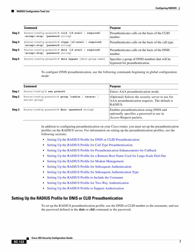
Configuring RADIUSRADIUS Configuration Task List
SC-122Cisco IOS Security Configuration Guide
To configure DNIS preauthentication, use the following commands beginning in global configuration mode:
In addition to configuring preauthentication on your Cisco router, you must set up the preauthentication profiles on the RADIUS server. For information on setting up the preauthentication profiles, see the following sections:
• Setting Up the RADIUS Profile for DNIS or CLID Preauthentication
• Setting Up the RADIUS Profile for Call Type Preauthentication
• Setting Up the RADIUS Profile for Preauthentication Enhancements for Callback
• Setting Up the RADIUS Profile for a Remote Host Name Used for Large-Scale Dial-Out
• Setting Up the RADIUS Profile for Modem Management
• Setting Up the RADIUS Profile for Subsequent Authentication
• Setting Up the RADIUS Profile for Subsequent Authentication Type
• Setting Up the RADIUS Profile to Include the Username
• Setting Up the RADIUS Profile for Two-Way Authentication
• Setting Up the RADIUS Profile to Support Authorization
Setting Up the RADIUS Profile for DNIS or CLID Preauthentication
To set up the RADIUS preauthentication profile, use the DNIS or CLID number as the username, and use the password defined in the dnis or clid command as the password.
Step 3 Router(config-preauth)# clid [if-avail | required] [accept-stop] [password string]
Preauthenticates calls on the basis of the CLID number.
Step 4 Router(config-preauth)# ctype [if-avail | required] [accept-stop] [password string]
Preauthenticates calls on the basis of the call type.
Step 5 Router(config-preauth)# dnis [if-avail | required] [accept-stop] [password string]
Preauthenticates calls on the basis of the DNIS number.
Step 6 Router(config-preauth)# dnis bypass {dnis-group-name} Specifies a group of DNIS numbers that will be bypassed for preauthentication.
Command Purpose
Command Purpose
Step 1 Router(config)# aaa preauth Enters AAA preauthentication mode.
Step 2 Router(config-preauth)# group {radius | tacacs+ | server-group}
(Optional) Selects the security server to use for AAA preauthentication requests. The default is RADIUS.
Step 3 Router(config-preauth)# dnis [password string] Enables preauthentication using DNIS and optionally specifies a password to use in Access-Request packets.
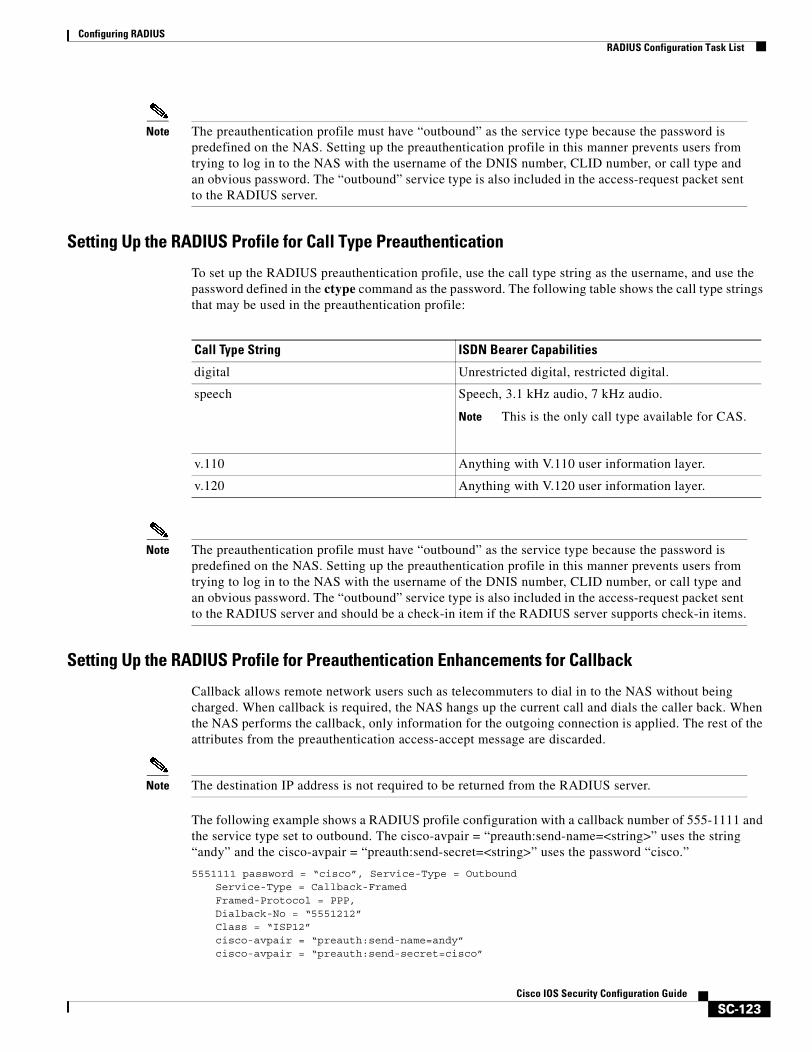
Configuring RADIUSRADIUS Configuration Task List
SC-123Cisco IOS Security Configuration Guide
Note The preauthentication profile must have “outbound” as the service type because the password is predefined on the NAS. Setting up the preauthentication profile in this manner prevents users from trying to log in to the NAS with the username of the DNIS number, CLID number, or call type and an obvious password. The “outbound” service type is also included in the access-request packet sent to the RADIUS server.
Setting Up the RADIUS Profile for Call Type Preauthentication
To set up the RADIUS preauthentication profile, use the call type string as the username, and use the password defined in the ctype command as the password. The following table shows the call type strings that may be used in the preauthentication profile:
Note The preauthentication profile must have “outbound” as the service type because the password is predefined on the NAS. Setting up the preauthentication profile in this manner prevents users from trying to log in to the NAS with the username of the DNIS number, CLID number, or call type and an obvious password. The “outbound” service type is also included in the access-request packet sent to the RADIUS server and should be a check-in item if the RADIUS server supports check-in items.
Setting Up the RADIUS Profile for Preauthentication Enhancements for Callback
Callback allows remote network users such as telecommuters to dial in to the NAS without being charged. When callback is required, the NAS hangs up the current call and dials the caller back. When the NAS performs the callback, only information for the outgoing connection is applied. The rest of the attributes from the preauthentication access-accept message are discarded.
Note The destination IP address is not required to be returned from the RADIUS server.
The following example shows a RADIUS profile configuration with a callback number of 555-1111 and the service type set to outbound. The cisco-avpair = “preauth:send-name=<string>” uses the string “andy” and the cisco-avpair = “preauth:send-secret=<string>” uses the password “cisco.”
5551111 password = “cisco”, Service-Type = OutboundService-Type = Callback-FramedFramed-Protocol = PPP,Dialback-No = “5551212”Class = “ISP12”cisco-avpair = “preauth:send-name=andy”cisco-avpair = “preauth:send-secret=cisco”
Call Type String ISDN Bearer Capabilities
digital Unrestricted digital, restricted digital.
speech Speech, 3.1 kHz audio, 7 kHz audio.
Note This is the only call type available for CAS.
v.110 Anything with V.110 user information layer.
v.120 Anything with V.120 user information layer.
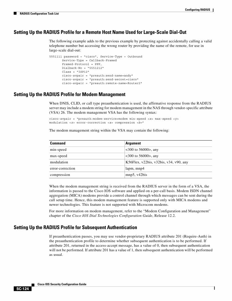
Configuring RADIUSRADIUS Configuration Task List
SC-124Cisco IOS Security Configuration Guide
Setting Up the RADIUS Profile for a Remote Host Name Used for Large-Scale Dial-Out
The following example adds to the previous example by protecting against accidentally calling a valid telephone number but accessing the wrong router by providing the name of the remote, for use in large-scale dial-out:
5551111 password = "cisco", Service-Type = Outbound Service-Type = Callback-Framed Framed-Protocol = PPP, Dialback-No = "5551212" Class = "ISP12" cisco-avpair = "preauth:send-name=andy" cisco-avpair = "preauth:send-secret=cisco" cisco-avpair = "preauth:remote-name=Router2"
Setting Up the RADIUS Profile for Modem Management
When DNIS, CLID, or call type preauthentication is used, the affirmative response from the RADIUS server may include a modem string for modem management in the NAS through vendor-specific attribute (VSA) 26. The modem management VSA has the following syntax:
cisco-avpair = “preauth:modem-service=modem min-speed <x> max-speed <y> modulation <z> error-correction <a> compression <b>”
The modem management string within the VSA may contain the following:
When the modem management string is received from the RADIUS server in the form of a VSA, the information is passed to the Cisco IOS software and applied on a per-call basis. Modem ISDN channel aggregation (MICA) modems provide a control channel through which messages can be sent during the call setup time. Hence, this modem management feature is supported only with MICA modems and newer technologies. This feature is not supported with Microcom modems.
For more information on modem management, refer to the “Modem Configuration and Management” chapter of the Cisco IOS Dial Technologies Configuration Guide, Release 12.2.
Setting Up the RADIUS Profile for Subsequent Authentication
If preauthentication passes, you may use vendor-proprietary RADIUS attribute 201 (Require-Auth) in the preauthentication profile to determine whether subsequent authentication is to be performed. If attribute 201, returned in the access-accept message, has a value of 0, then subsequent authentication will not be performed. If attribute 201 has a value of 1, then subsequent authentication will be performed as usual.
Command Argument
min-speed <300 to 56000>, any
max-speed <300 to 56000>, any
modulation K56Flex, v22bis, v32bis, v34, v90, any
error-correction lapm, mnp4
compression mnp5, v42bis
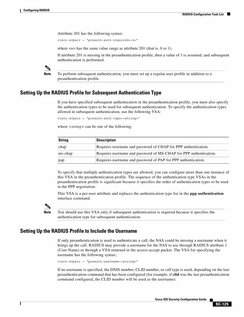
Configuring RADIUSRADIUS Configuration Task List
SC-125Cisco IOS Security Configuration Guide
Attribute 201 has the following syntax:
cisco-avpair = “preauth:auth-required=<n>”
where <n> has the same value range as attribute 201 (that is, 0 or 1).
If attribute 201 is missing in the preauthentication profile, then a value of 1 is assumed, and subsequent authentication is performed.
Note To perform subsequent authentication, you must set up a regular user profile in addition to a preauthentication profile.
Setting Up the RADIUS Profile for Subsequent Authentication Type
If you have specified subsequent authentication in the preauthentication profile, you must also specify the authentication types to be used for subsequent authentication. To specify the authentication types allowed in subsequent authentication, use the following VSA:
cisco-avpair = “preauth:auth-type=<string>”
where <string> can be one of the following:
To specify that multiple authentication types are allowed, you can configure more than one instance of this VSA in the preauthentication profile. The sequence of the authentication type VSAs in the preauthentication profile is significant because it specifies the order of authentication types to be used in the PPP negotiation.
This VSA is a per-user attribute and replaces the authentication type list in the ppp authentication interface command.
Note You should use this VSA only if subsequent authentication is required because it specifies the authentication type for subsequent authentication.
Setting Up the RADIUS Profile to Include the Username
If only preauthentication is used to authenticate a call, the NAS could be missing a username when it brings up the call. RADIUS may provide a username for the NAS to use through RADIUS attribute 1 (User-Name) or through a VSA returned in the access-accept packet. The VSA for specifying the username has the following syntax:
cisco-avpair = “preauth:username=<string>”
If no username is specified, the DNIS number, CLID number, or call type is used, depending on the last preauthentication command that has been configured (for example, if clid was the last preauthentication command configured, the CLID number will be used as the username).
String Description
chap Requires username and password of CHAP for PPP authentication.
ms-chap Requires username and password of MS-CHAP for PPP authentication.
pap Requires username and password of PAP for PPP authentication.
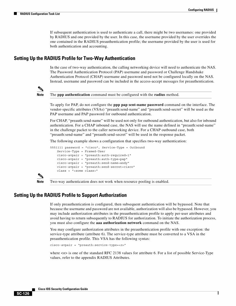
Configuring RADIUSRADIUS Configuration Task List
SC-126Cisco IOS Security Configuration Guide
If subsequent authentication is used to authenticate a call, there might be two usernames: one provided by RADIUS and one provided by the user. In this case, the username provided by the user overrides the one contained in the RADIUS preauthentication profile; the username provided by the user is used for both authentication and accounting.
Setting Up the RADIUS Profile for Two-Way Authentication
In the case of two-way authentication, the calling networking device will need to authenticate the NAS. The Password Authentication Protocol (PAP) username and password or Challenge Handshake Authentication Protocol (CHAP) username and password need not be configured locally on the NAS. Instead, username and password can be included in the access-accept messages for preauthentication.
Note The ppp authentication command must be configured with the radius method.
To apply for PAP, do not configure the ppp pap sent-name password command on the interface. The vendor-specific attributes (VSAs) “preauth:send-name” and “preauth:send-secret” will be used as the PAP username and PAP password for outbound authentication.
For CHAP, “preauth:send-name” will be used not only for outbound authentication, but also for inbound authentication. For a CHAP inbound case, the NAS will use the name defined in “preauth:send-name” in the challenge packet to the caller networking device. For a CHAP outbound case, both “preauth:send-name” and “preauth:send-secret” will be used in the response packet.
The following example shows a configuration that specifies two-way authentication:
5551111 password = "cisco", Service-Type = Outbound Service-Type = Framed-User cisco-avpair = "preauth:auth-required=1" cisco-avpair = "preauth:auth-type=pap" cisco-avpair = "preauth:send-name=andy" cisco-avpair = "preauth:send-secret=cisco" class = "<some class>"
Note Two-way authentication does not work when resource pooling is enabled.
Setting Up the RADIUS Profile to Support Authorization
If only preauthentication is configured, then subsequent authentication will be bypassed. Note that because the username and password are not available, authorization will also be bypassed. However, you may include authorization attributes in the preauthentication profile to apply per-user attributes and avoid having to return subsequently to RADIUS for authorization. To initiate the authorization process, you must also configure the aaa authorization network command on the NAS.
You may configure authorization attributes in the preauthentication profile with one exception: the service-type attribute (attribute 6). The service-type attribute must be converted to a VSA in the preauthentication profile. This VSA has the following syntax:
cisco-avpair = “preauth:service-type=<n>”
where <n> is one of the standard RFC 2138 values for attribute 6. For a list of possible Service-Type values, refer to the appendix RADIUS Attributes.
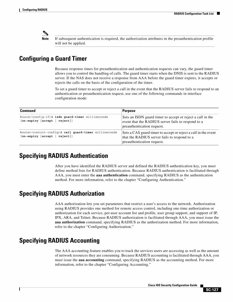
Configuring RADIUSRADIUS Configuration Task List
SC-127Cisco IOS Security Configuration Guide
Note If subsequent authentication is required, the authorization attributes in the preauthentication profile will not be applied.
Configuring a Guard TimerBecause response times for preauthentication and authentication requests can vary, the guard timer allows you to control the handling of calls. The guard timer starts when the DNIS is sent to the RADIUS server. If the NAS does not receive a response from AAA before the guard timer expires, it accepts or rejects the calls on the basis of the configuration of the timer.
To set a guard timer to accept or reject a call in the event that the RADIUS server fails to respond to an authentication or preauthentication request, use one of the following commands in interface configuration mode:
Specifying RADIUS AuthenticationAfter you have identified the RADIUS server and defined the RADIUS authentication key, you must define method lists for RADIUS authentication. Because RADIUS authentication is facilitated through AAA, you must enter the aaa authentication command, specifying RADIUS as the authentication method. For more information, refer to the chapter “Configuring Authentication.”
Specifying RADIUS AuthorizationAAA authorization lets you set parameters that restrict a user’s access to the network. Authorization using RADIUS provides one method for remote access control, including one-time authorization or authorization for each service, per-user account list and profile, user group support, and support of IP, IPX, ARA, and Telnet. Because RADIUS authorization is facilitated through AAA, you must issue the aaa authorization command, specifying RADIUS as the authorization method. For more information, refer to the chapter “Configuring Authorization.”
Specifying RADIUS AccountingThe AAA accounting feature enables you to track the services users are accessing as well as the amount of network resources they are consuming. Because RADIUS accounting is facilitated through AAA, you must issue the aaa accounting command, specifying RADIUS as the accounting method. For more information, refer to the chapter “Configuring Accounting.”
Command Purpose
Router(config-if)# isdn guard-timer milliseconds [on-expiry {accept | reject}]
Sets an ISDN guard timer to accept or reject a call in the event that the RADIUS server fails to respond to a preauthentication request.
Router(control-config)# call guard-timer milliseconds [on-expiry {accept | reject}]
Sets a CAS guard timer to accept or reject a call in the event that the RADIUS server fails to respond to a preauthentication request.
Configuring RADIUSRADIUS Configuration Task List
SC-128Cisco IOS Security Configuration Guide
Configuring RADIUS Login-IP-HostTo enable the network access server to attempt more than one login host when trying to connect a dial in user, you can enter as many as three Login-IP-Host entries in the user’s profile on the RADIUS server. The following example shows that three Login-IP-Host instances have been configured for the user joeuser, and that TCP-Clear will be used for the connection:
joeuser Password = xyz Service-Type = Login, Login-Service = TCP-Clear, Login-IP-Host = 10.0.0.0, Login-IP-Host = 10.2.2.2, Login-IP-Host = 10.255.255.255, Login-TCP-Port = 23
The order in which the hosts are entered is the order in which they are attempted. Use the ip tcp synwait-time command to set the number of seconds that the network access server waits before trying to connect to the next host on the list; the default is 30 seconds.
Your RADIUS server might permit more than three Login-IP-Host entries; however, the network access server supports only three hosts in access-accept packets.
Configuring RADIUS PromptTo control whether user responses to access-challenge packets are echoed to the screen, you can configure the Prompt attribute in the user profile on the RADIUS server. This attribute is included only in access-challenge packets. The following example shows the Prompt attribute set to No-Echo, which prevents the user's responses from echoing:
joeuser Password = xyz Service-Type = Login, Login-Service = Telnet, Prompt = No-Echo, Login-IP-Host = 172.31.255.255
To allow user responses to echo, set the attribute to Echo. If the Prompt attribute is not included in the user profile, responses are echoed by default.
This attribute overrides the behavior of the radius-server challenge-noecho command configured on the access server. For example, if the access server is configured to suppress echoing, but the individual user profile allows echoing, then the user responses are echoed.
Note To use the Prompt attribute, your RADIUS server must be configured to support access-challenge packets.
Configuring RADIUSMonitoring and Maintaining RADIUS
SC-129Cisco IOS Security Configuration Guide
Configuring Suffix and Password in RADIUS Access RequestsLarge-scale dial-out eliminates the need to configure dialer maps on every NAS for every destination. Instead, you can create remote site profiles that contain outgoing call attributes on the AAA server. The profile is downloaded by the NAS when packet traffic requires a call to be placed to a remote site.
You can configure the username in the access-request message to RADIUS. The default suffix of the username, “-out,” is appended to the username. The format for composing the username attribute is IP address plus configured suffix.
To provide username configuration capability for large-scale dial-out, the dialer aaa command is implemented with the new suffix and password keywords.
Monitoring and Maintaining RADIUSTo monitor and maintain RADIUS, use the following commands in privileged EXEC mode:
RADIUS AttributesThe network access server monitors the RADIUS authorization and accounting functions defined by RADIUS attributes in each user-profile. For a list of supported RADIUS attributes, refer to the appendix “RADIUS Attributes.”
This section includes the following sections:
• Vendor-Proprietary RADIUS Attributes
• RADIUS Tunnel Attributes
Command Purpose
Step 1 Router(config)# aaa new-model Enables the AAA access control model.
Step 2 Router(config)# aaa route download min Enables the download static route feature and sets the amount of time between downloads.
Step 3 Router(config)# aaa authorization configuration default
Downloads static route configuration information from the AAA server using TACACS+ or RADIUS.
Step 4 Router(config)# interface dialer 1 Defines a dialer rotary group.
Step 5 Router(config-if)# dialer aaa Allows a dialer to access the AAA server for dialing information.
Step 6 Router(config-if)# dialer aaa suffix suffix password password
Allows a dialer to access the AAA server for dialing information and specifies a suffix and nondefault password for authentication.
Command Purpose
Router# debug radius Displays information associated with RADIUS.
Router# show radius statistics Displays the RADIUS statistics for accounting and authentication packets.

Configuring RADIUSRADIUS Configuration Examples
SC-130Cisco IOS Security Configuration Guide
Vendor-Proprietary RADIUS AttributesAn Internet Engineering Task Force (IETF) draft standard for RADIUS specifies a method for communicating vendor-proprietary information between the network access server and the RADIUS server. Some vendors, nevertheless, have extended the RADIUS attribute set in a unique way. Cisco IOS software supports a subset of vendor-proprietary RADIUS attributes. For a list of supported vendor-proprietary RADIUS attributes, refer to the appendix “RADIUS Attributes.”
RADIUS Tunnel AttributesRADIUS is a security server authentication, authorization, and accounting (AAA) protocol originally developed by Livingston, Inc. RADIUS uses attribute value (AV) pairs to communicate information between the security server and the network access server. RFC 2138 and RFC 2139 describe the basic functionality of RADIUS and the original set of Internet Engineering Task Force (IETF)-standard AV pairs used to send AAA information. Two draft IETF standards, “RADIUS Attributes for Tunnel Protocol Support” and “RADIUS Accounting Modifications for Tunnel Protocol Support,” extend the IETF-defined set of AV pairs to include attributes specific to virtual private networks (VPNs); these attributes are used to carry the tunneling information between the RADIUS server and the tunnel initiator. RFC 2865 and RFC 2868 extend the IETF-defined set of AV pairs to include attributes specific to compulsory tunneling in VPNs by allowing the user to specify authentication names for the network access server and the RADIUS server.
Cisco routers and access servers now support new RADIUS IETF-standard VPDN tunnel attributes. These new RADIUS IETF-standard attributes are listed in the “RADIUS Attributes” appendix. Refer to the following three configuration examples later in this chapter:
• RADIUS User Profile with RADIUS Tunneling Attributes Example
• L2TP Access Concentrator Examples
• L2TP Network Server Examples
For more information about L2F, L2TP, VPN, or VPDN, refer to the Cisco IOS Dial Technologies Configuration Guide, Release 12.2.
RADIUS Configuration ExamplesThe following sections provide RADIUS configuration examples:
• RADIUS Authentication and Authorization Example
• RADIUS Authentication, Authorization, and Accounting Example
• Vendor-Proprietary RADIUS Configuration Example
• RADIUS Server with Server-Specific Values Example
• Multiple RADIUS Servers with Global and Server-Specific Values Example
• Multiple RADIUS Server Entries for the Same Server IP Address Example
• RADIUS Server Group Examples
• Multiple RADIUS Server Entries Using AAA Server Groups Example
• AAA Server Group Selection Based on DNIS Example
• AAA Preauthentication Examples
Configuring RADIUSRADIUS Configuration Examples
SC-131Cisco IOS Security Configuration Guide
• RADIUS User Profile with RADIUS Tunneling Attributes Example
• Guard Timer Examples
• L2TP Access Concentrator Examples
• L2TP Network Server Examples
RADIUS Authentication and Authorization ExampleThe following example shows how to configure the router to authenticate and authorize using RADIUS:
aaa authentication login use-radius group radius localaaa authentication ppp user-radius if-needed group radiusaaa authorization exec default group radiusaaa authorization network default group radius
The lines in this sample RADIUS authentication and authorization configuration are defined as follows:
• The aaa authentication login use-radius group radius local command configures the router to use RADIUS for authentication at the login prompt. If RADIUS returns an error, the user is authenticated using the local database. In this example, use-radius is the name of the method list, which specifies RADIUS and then local authentication.
• The aaa authentication ppp user-radius if-needed group radius command configures the Cisco IOS software to use RADIUS authentication for lines using PPP with CHAP or PAP if the user has not already been authorized. If the EXEC facility has authenticated the user, RADIUS authentication is not performed. In this example, user-radius is the name of the method list defining RADIUS as the if-needed authentication method.
• The aaa authorization exec default group radius command sets the RADIUS information that is used for EXEC authorization, autocommands, and access lists.
• The aaa authorization network default group radius command sets RADIUS for network authorization, address assignment, and access lists.
RADIUS Authentication, Authorization, and Accounting ExampleThe following example shows a general configuration using RADIUS with the AAA command set:
radius-server host 123.45.1.2radius-server key myRaDiUSpassWoRdusername root password ALongPasswordaaa authentication ppp dialins group radius localaaa authorization network default group radius localaaa accounting network default start-stop group radiusaaa authentication login admins localaaa authorization exec default localline 1 16autoselect pppautoselect during-loginlogin authentication adminsmodem ri-is-cd
interface group-async 1encaps pppppp authentication pap dialins
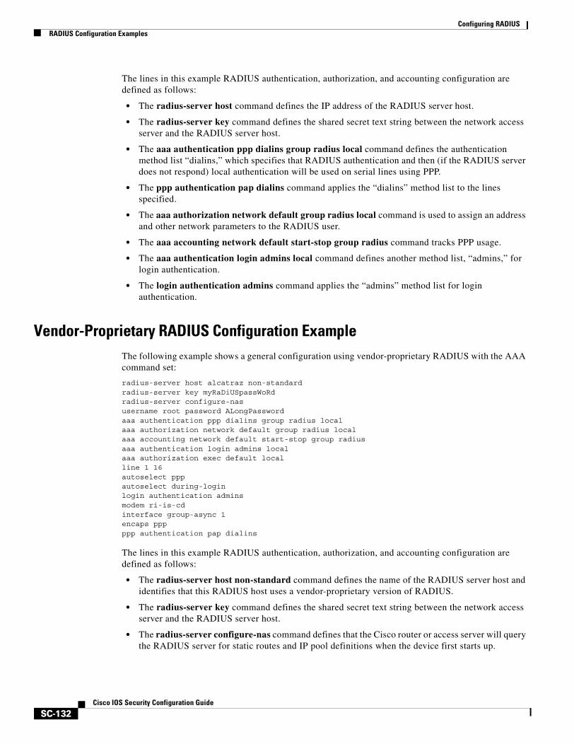
Configuring RADIUSRADIUS Configuration Examples
SC-132Cisco IOS Security Configuration Guide
The lines in this example RADIUS authentication, authorization, and accounting configuration are defined as follows:
• The radius-server host command defines the IP address of the RADIUS server host.
• The radius-server key command defines the shared secret text string between the network access server and the RADIUS server host.
• The aaa authentication ppp dialins group radius local command defines the authentication method list “dialins,” which specifies that RADIUS authentication and then (if the RADIUS server does not respond) local authentication will be used on serial lines using PPP.
• The ppp authentication pap dialins command applies the “dialins” method list to the lines specified.
• The aaa authorization network default group radius local command is used to assign an address and other network parameters to the RADIUS user.
• The aaa accounting network default start-stop group radius command tracks PPP usage.
• The aaa authentication login admins local command defines another method list, “admins,” for login authentication.
• The login authentication admins command applies the “admins” method list for login authentication.
Vendor-Proprietary RADIUS Configuration ExampleThe following example shows a general configuration using vendor-proprietary RADIUS with the AAA command set:
radius-server host alcatraz non-standardradius-server key myRaDiUSpassWoRdradius-server configure-nasusername root password ALongPasswordaaa authentication ppp dialins group radius localaaa authorization network default group radius localaaa accounting network default start-stop group radiusaaa authentication login admins localaaa authorization exec default localline 1 16autoselect pppautoselect during-loginlogin authentication adminsmodem ri-is-cdinterface group-async 1encaps pppppp authentication pap dialins
The lines in this example RADIUS authentication, authorization, and accounting configuration are defined as follows:
• The radius-server host non-standard command defines the name of the RADIUS server host and identifies that this RADIUS host uses a vendor-proprietary version of RADIUS.
• The radius-server key command defines the shared secret text string between the network access server and the RADIUS server host.
• The radius-server configure-nas command defines that the Cisco router or access server will query the RADIUS server for static routes and IP pool definitions when the device first starts up.
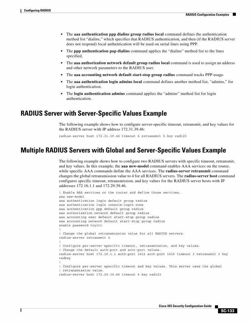
Configuring RADIUSRADIUS Configuration Examples
SC-133Cisco IOS Security Configuration Guide
• The aaa authentication ppp dialins group radius local command defines the authentication method list “dialins,” which specifies that RADIUS authentication, and then (if the RADIUS server does not respond) local authentication will be used on serial lines using PPP.
• The ppp authentication pap dialins command applies the “dialins” method list to the lines specified.
• The aaa authorization network default group radius local command is used to assign an address and other network parameters to the RADIUS user.
• The aaa accounting network default start-stop group radius command tracks PPP usage.
• The aaa authentication login admins local command defines another method list, “admins,” for login authentication.
• The login authentication admins command applies the “admins” method list for login authentication.
RADIUS Server with Server-Specific Values ExampleThe following example shows how to configure server-specific timeout, retransmit, and key values for the RADIUS server with IP address 172.31.39.46:
radius-server host 172.31.39.46 timeout 6 retransmit 5 key rad123
Multiple RADIUS Servers with Global and Server-Specific Values ExampleThe following example shows how to configure two RADIUS servers with specific timeout, retransmit, and key values. In this example, the aaa new-model command enables AAA services on the router, while specific AAA commands define the AAA services. The radius-server retransmit command changes the global retransmission value to 4 for all RADIUS servers. The radius-server host command configures specific timeout, retransmission, and key values for the RADIUS server hosts with IP addresses 172.16.1.1 and 172.29.39.46.
! Enable AAA services on the router and define those services.aaa new-modelaaa authentication login default group radiusaaa authentication login console-login noneaaa authentication ppp default group radiusaaa authorization network default group radiusaaa accounting exec default start-stop group radiusaaa accounting network default start-stop group radiusenable password tryit1!! Change the global retransmission value for all RADIUS servers.radius-server retransmit 4!! Configure per-server specific timeout, retransmission, and key values. ! Change the default auth-port and acct-port values. radius-server host 172.16.1.1 auth-port 1612 acct-port 1616 timeout 3 retransmit 3 key radkey!! Configure per-server specific timeout and key values. This server uses the global! retransmission value.radius-server host 172.29.39.46 timeout 6 key rad123
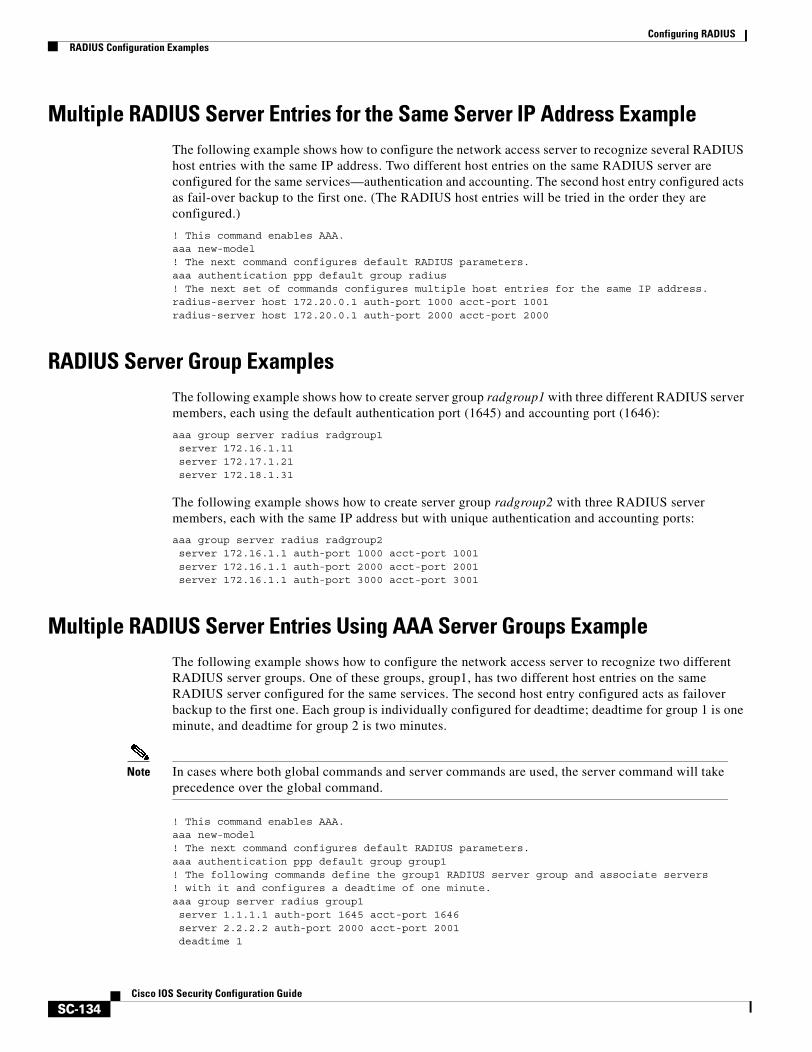
Configuring RADIUSRADIUS Configuration Examples
SC-134Cisco IOS Security Configuration Guide
Multiple RADIUS Server Entries for the Same Server IP Address ExampleThe following example shows how to configure the network access server to recognize several RADIUS host entries with the same IP address. Two different host entries on the same RADIUS server are configured for the same services—authentication and accounting. The second host entry configured acts as fail-over backup to the first one. (The RADIUS host entries will be tried in the order they are configured.)
! This command enables AAA.aaa new-model! The next command configures default RADIUS parameters.aaa authentication ppp default group radius! The next set of commands configures multiple host entries for the same IP address.radius-server host 172.20.0.1 auth-port 1000 acct-port 1001radius-server host 172.20.0.1 auth-port 2000 acct-port 2000
RADIUS Server Group ExamplesThe following example shows how to create server group radgroup1 with three different RADIUS server members, each using the default authentication port (1645) and accounting port (1646):
aaa group server radius radgroup1server 172.16.1.11 server 172.17.1.21 server 172.18.1.31
The following example shows how to create server group radgroup2 with three RADIUS server members, each with the same IP address but with unique authentication and accounting ports:
aaa group server radius radgroup2server 172.16.1.1 auth-port 1000 acct-port 1001server 172.16.1.1 auth-port 2000 acct-port 2001server 172.16.1.1 auth-port 3000 acct-port 3001
Multiple RADIUS Server Entries Using AAA Server Groups ExampleThe following example shows how to configure the network access server to recognize two different RADIUS server groups. One of these groups, group1, has two different host entries on the same RADIUS server configured for the same services. The second host entry configured acts as failover backup to the first one. Each group is individually configured for deadtime; deadtime for group 1 is one minute, and deadtime for group 2 is two minutes.
Note In cases where both global commands and server commands are used, the server command will take precedence over the global command.
! This command enables AAA.aaa new-model! The next command configures default RADIUS parameters.aaa authentication ppp default group group1! The following commands define the group1 RADIUS server group and associate servers! with it and configures a deadtime of one minute.aaa group server radius group1server 1.1.1.1 auth-port 1645 acct-port 1646server 2.2.2.2 auth-port 2000 acct-port 2001deadtime 1
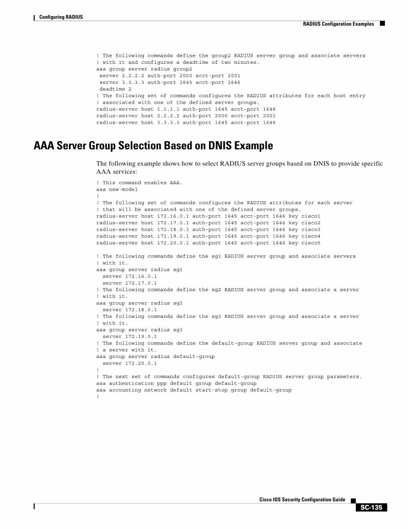
Configuring RADIUSRADIUS Configuration Examples
SC-135Cisco IOS Security Configuration Guide
! The following commands define the group2 RADIUS server group and associate servers! with it and configures a deadtime of two minutes.aaa group server radius group2server 2.2.2.2 auth-port 2000 acct-port 2001server 3.3.3.3 auth-port 1645 acct-port 1646deadtime 2
! The following set of commands configures the RADIUS attributes for each host entry! associated with one of the defined server groups.radius-server host 1.1.1.1 auth-port 1645 acct-port 1646radius-server host 2.2.2.2 auth-port 2000 acct-port 2001radius-server host 3.3.3.3 auth-port 1645 acct-port 1646
AAA Server Group Selection Based on DNIS ExampleThe following example shows how to select RADIUS server groups based on DNIS to provide specific AAA services:
! This command enables AAA.aaa new-model!! The following set of commands configures the RADIUS attributes for each server! that will be associated with one of the defined server groups.radius-server host 172.16.0.1 auth-port 1645 acct-port 1646 key cisco1radius-server host 172.17.0.1 auth-port 1645 acct-port 1646 key cisco2radius-server host 172.18.0.1 auth-port 1645 acct-port 1646 key cisco3 radius-server host 172.19.0.1 auth-port 1645 acct-port 1646 key cisco4 radius-server host 172.20.0.1 auth-port 1645 acct-port 1646 key cisco5
! The following commands define the sg1 RADIUS server group and associate servers ! with it.aaa group server radius sg1
server 172.16.0.1server 172.17.0.1
! The following commands define the sg2 RADIUS server group and associate a server! with it.aaa group server radius sg2
server 172.18.0.1! The following commands define the sg3 RADIUS server group and associate a server! with it.aaa group server radius sg3
server 172.19.0.1! The following commands define the default-group RADIUS server group and associate! a server with it.aaa group server radius default-group
server 172.20.0.1!! The next set of commands configures default-group RADIUS server group parameters.aaa authentication ppp default group default-groupaaa accounting network default start-stop group default-group!
Configuring RADIUSRADIUS Configuration Examples
SC-136Cisco IOS Security Configuration Guide
! The next set of commands enables DNIS mapping and maps DNIS numbers to the defined! RADIUS server groups. In this configuration, all PPP connection requests using ! DNIS 7777 are sent to the sg1 server group. The accounting records for these! connections (specifically, start-stop records) are handled by the sg2 server group.! Calls with a DNIS of 8888 use server group sg3 for authentication and server group! default-group for accounting. Calls with a DNIS of 9999 use server group! default-group for authentication and server group sg3 for accounting records! (stop records only). All other calls with DNIS other than the ones defined use the! server group default-group for both authentication and stop-start accounting records.aaa dnis map enableaaa dnis map 7777 authentication ppp group sg1aaa dnis map 7777 accounting network start-stop group sg2aaa dnis map 8888 authentication ppp group sg3aaa dnis map 9999 accounting network stop-only group sg3
AAA Preauthentication ExamplesThe following example shows a simple configuration that specifies that the DNIS number be used for preauthentication:
aaa preauth group radius dnis required
The following example shows a configuration that specifies that both the DNIS number and the CLID number be used for preauthentication. DNIS preauthentication will be performed first, followed by CLID preauthentication.
aaa preauth group radius dnis required clid required
The following example specifies that preauthentication be performed on all DNIS numbers except the two DNIS numbers specified in the DNIS group called “hawaii”:
aaa preauth group radius dnis required dnis bypass hawaii
dialer dnis group hawaii number 12345 number 12346
The following example shows a sample AAA configuration with DNIS preauthentication:
aaa new-modelaaa authentication login CONSOLE noneaaa authentication login RADIUS_LIST group radiusaaa authentication login TAC_PLUS group tacacs+ enableaaa authentication login V.120 noneaaa authentication enable default enable group tacacs+aaa authentication ppp RADIUS_LIST if-needed group radiusaaa authorization exec RADIUS_LIST group radius if-authenticatedaaa authorization exec V.120 noneaaa authorization network default group radius if-authenticatedaaa authorization network RADIUS_LIST if-authenticated group radiusaaa authorization network V.120 group radius if-authenticatedaaa accounting suppress null-usernameaaa accounting exec default start-stop group radiusaaa accounting commands 0 default start-stop group radius
Configuring RADIUSRADIUS Configuration Examples
SC-137Cisco IOS Security Configuration Guide
aaa accounting network default start-stop group radiusaaa accounting connection default start-stop group radiusaaa accounting system default start-stop group radiusaaa preauth dnis password Cisco-DNISaaa nas port extended!radius-server configure-nasradius-server host 10.0.0.0 auth-port 1645 acct-port 1646 non-standardradius-server host 10.255.255.255 auth-port 1645 acct-port 1646 non-standardradius-server retransmit 2radius-server deadtime 1radius-server attribute nas-port format cradius-server unique-ident 18radius-server key MyKey
Note To configure preauthentication, you must also set up preauthentication profiles on the RADIUS server.
RADIUS User Profile with RADIUS Tunneling Attributes ExampleThe following example shows a RADIUS user profile (Merit Daemon format) that includes RADIUS tunneling attributes. This entry supports two tunnels, one for L2F and the other for L2TP. The tag entries with :1 support L2F tunnels, and the tag entries with :2 support L2TP tunnels.
cisco.com Password = "cisco", Service-Type = OutboundService-Type = Outbound,Tunnel-Type = :1:L2F,Tunnel-Medium-Type = :1:IP,Tunnel-Client-Endpoint = :1:"10.0.0.2",Tunnel-Server-Endpoint = :1:"10.0.0.3",Tunnel-Client-Auth-Id = :1:"l2f-cli-auth-id",Tunnel-Server-Auth-Id = :1:"l2f-svr-auth-id",Tunnel-Assignment-Id = :1:"l2f-assignment-id",Cisco-Avpair = "vpdn:nas-password=l2f-cli-pass",Cisco-Avpair = "vpdn:gw-password=l2f-svr-pass",Tunnel-Preference = :1:1,Tunnel-Type = :2:L2TP,Tunnel-Medium-Type = :2:IP,Tunnel-Client-Endpoint = :2:"10.0.0.2",Tunnel-Server-Endpoint = :2:"10.0.0.3",Tunnel-Client-Auth-Id = :2:"l2tp-cli-auth-id",Tunnel-Server-Auth-Id = :2:"l2tp-svr-auth-id",Tunnel-Assignment-Id = :2:"l2tp-assignment-id",Cisco-Avpair = "vpdn:l2tp-tunnel-password=l2tp-tnl-pass",Tunnel-Preference = :2:2
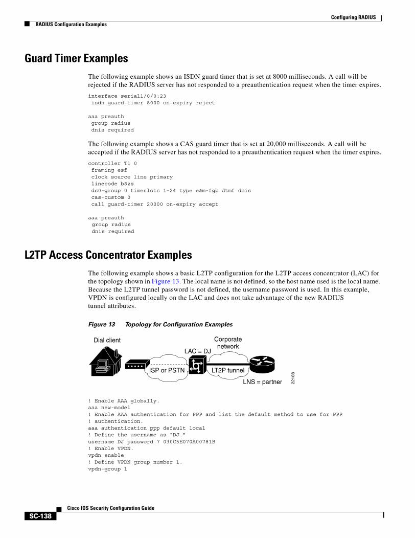
Configuring RADIUSRADIUS Configuration Examples
SC-138Cisco IOS Security Configuration Guide
Guard Timer ExamplesThe following example shows an ISDN guard timer that is set at 8000 milliseconds. A call will be rejected if the RADIUS server has not responded to a preauthentication request when the timer expires.
interface serial1/0/0:23 isdn guard-timer 8000 on-expiry reject
aaa preauth group radius dnis required
The following example shows a CAS guard timer that is set at 20,000 milliseconds. A call will be accepted if the RADIUS server has not responded to a preauthentication request when the timer expires.
controller T1 0 framing esf clock source line primary linecode b8zs ds0-group 0 timeslots 1-24 type e&m-fgb dtmf dnis cas-custom 0 call guard-timer 20000 on-expiry accept
aaa preauthgroup radiusdnis required
L2TP Access Concentrator ExamplesThe following example shows a basic L2TP configuration for the L2TP access concentrator (LAC) for the topology shown in Figure 13. The local name is not defined, so the host name used is the local name. Because the L2TP tunnel password is not defined, the username password is used. In this example, VPDN is configured locally on the LAC and does not take advantage of the new RADIUS tunnel attributes.
Figure 13 Topology for Configuration Examples
! Enable AAA globally.aaa new-model! Enable AAA authentication for PPP and list the default method to use for PPP! authentication.aaa authentication ppp default local! Define the username as “DJ.”username DJ password 7 030C5E070A00781B! Enable VPDN.vpdn enable! Define VPDN group number 1.vpdn-group 1
Dial client
ISP or PSTN
Corporatenetwork
LT2P tunnel
LAC = DJ
LNS = partner 22
10
8
Configuring RADIUSRADIUS Configuration Examples
SC-139Cisco IOS Security Configuration Guide
! Allow the LAC to respond to dialin requests using L2TP from IP address 172.21.9.13! domain “cisco.com.”request dialin protocol l2tpdomain cisco.cominitiate-ip to 172.21.9.13 local name nas-1
The following example shows how to configure the LAC if RADIUS tunnel attributes are supported. In this example, there is no local VPDN configuration on the LAC; the LAC, instead, is configured to query the remote RADIUS security server.
! Enable global AAA securities services.aaa new-model! Enable AAA authentication for PPP and list RADIUS as the default method to use! for PPP authentication.aaa authentication ppp default group radius local! Enable AAA (network) authorization and list RADIUS as the default method to use for! authorization.aaa authorization network default group radius! Define the username as “DJ.”username DJ password 7 030C5E070A00781B! Enable VPDN.vpdn enable! Configure the LAC to interface with the remote RADIUS security server.radius host 171.69.1.1 auth-port 1645 acct-port 1646radius-server key cisco
L2TP Network Server ExamplesThe following example shows a basic L2TP configuration with corresponding comments on the L2TP network server (LNS) for the topology shown in Figure 13:
! Enable AAA globally.aaa new-model! Enable AAA authentication for PPP and list the default method to use for PPP! authentication.aaa authentication ppp default local! Define the username as “partner.”username partner password 7 030C5E070A00781B! Create virtual-template 1 and assign all values for virtual access interfaces.interface Virtual-Template1! Borrow the IP address from interface ethernet 1. ip unnumbered Ethernet0! Disable multicast fast switching. no ip mroute-cache! Use CHAP to authenticate PPP. ppp authentication chap! Enable VPDN.vpdn enable! Create vpdn-group number 1.vpdn-group 1! Accept all dialin l2tp tunnels from virtual-template 1 from remote peer DJ.accept dialin l2tp virtual-template 1 remote DJprotocol anyvirtual-template 1
terminate-from hostname nas1local name hgw1
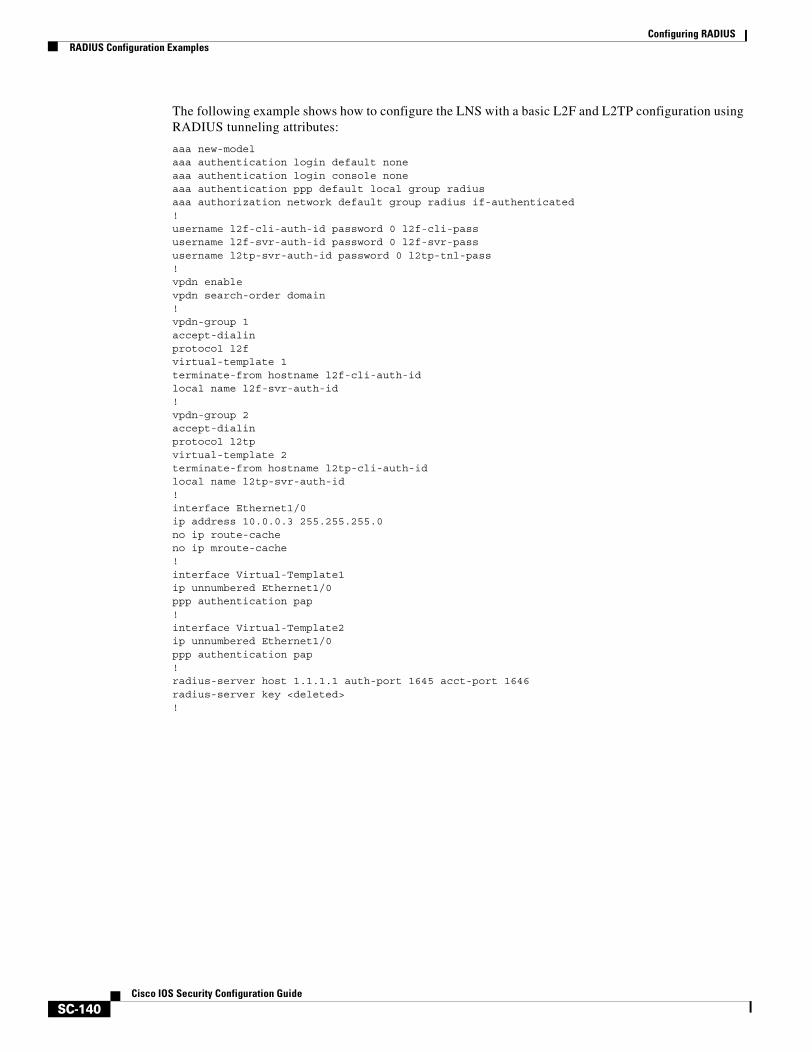
Configuring RADIUSRADIUS Configuration Examples
SC-140Cisco IOS Security Configuration Guide
The following example shows how to configure the LNS with a basic L2F and L2TP configuration using RADIUS tunneling attributes:
aaa new-modelaaa authentication login default noneaaa authentication login console noneaaa authentication ppp default local group radiusaaa authorization network default group radius if-authenticated! username l2f-cli-auth-id password 0 l2f-cli-passusername l2f-svr-auth-id password 0 l2f-svr-passusername l2tp-svr-auth-id password 0 l2tp-tnl-pass! vpdn enablevpdn search-order domain!vpdn-group 1accept-dialinprotocol l2fvirtual-template 1terminate-from hostname l2f-cli-auth-idlocal name l2f-svr-auth-id!vpdn-group 2accept-dialinprotocol l2tpvirtual-template 2terminate-from hostname l2tp-cli-auth-idlocal name l2tp-svr-auth-id!interface Ethernet1/0ip address 10.0.0.3 255.255.255.0no ip route-cacheno ip mroute-cache!interface Virtual-Template1ip unnumbered Ethernet1/0ppp authentication pap!interface Virtual-Template2ip unnumbered Ethernet1/0ppp authentication pap!radius-server host 1.1.1.1 auth-port 1645 acct-port 1646radius-server key <deleted>!
SC-141Cisco IOS Security Configuration Guide
Configuring TACACS+
This chapter discusses how to enable and configure TACACS+, which provides detailed accounting information and flexible administrative control over authentication and authorization processes. TACACS+ is facilitated through AAA and can be enabled only through AAA commands.
For a complete description of the TACACS+ commands used in this chapter, refer to the chapter “TACACS+ Commands” in the Cisco IOS Security Command Reference. To locate documentation of other commands that appear in this chapter, use the command reference master index or search online.
To identify the hardware platform or software image information associated with a feature, use the Feature Navigator on Cisco.com to search for information about the feature, or refer to the software release notes for a specific release. For more information, see the section “Identifying Supported Platforms” in the chapter “Using Cisco IOS Software.”
In This ChapterThis chapter includes the following sections:
• About TACACS+
• TACACS+ Operation
• TACACS+ Configuration Task List
• TACACS+ AV Pairs
• TACACS+ Configuration Examples
About TACACS+TACACS+ is a security application that provides centralized validation of users attempting to gain access to a router or network access server. TACACS+ services are maintained in a database on a TACACS+ daemon running, typically, on a UNIX or Windows NT workstation. You must have access to and must configure a TACACS+ server before the configured TACACS+ features on your network access server are available.
TACACS+ provides for separate and modular authentication, authorization, and accounting facilities. TACACS+ allows for a single access control server (the TACACS+ daemon) to provide each service—authentication, authorization, and accounting—independently. Each service can be tied into its own database to take advantage of other services available on that server or on the network, depending on the capabilities of the daemon.
Configuring TACACS+TACACS+ Operation
SC-142Cisco IOS Security Configuration Guide
The goal of TACACS+ is to provide a methodology for managing multiple network access points from a single management service. The Cisco family of access servers and routers and the Cisco IOS user interface (for both routers and access servers) can be network access servers.
Network access points enable traditional “dumb” terminals, terminal emulators, workstations, personal computers (PCs), and routers in conjunction with suitable adapters (for example, modems or ISDN adapters) to communicate using protocols such as Point-to-Point Protocol (PPP), Serial Line Internet Protocol (SLIP), Compressed SLIP (CSLIP), or AppleTalk Remote Access (ARA) protocol. In other words, a network access server provides connections to a single user, to a network or subnetwork, and to interconnected networks. The entities connected to the network through a network access server are called network access clients; for example, a PC running PPP over a voice-grade circuit is a network access client. TACACS+, administered through the AAA security services, can provide the following services:
• Authentication—Provides complete control of authentication through login and password dialog, challenge and response, messaging support.
The authentication facility provides the ability to conduct an arbitrary dialog with the user (for example, after a login and password are provided, to challenge a user with a number of questions, like home address, mother’s maiden name, service type, and social security number). In addition, the TACACS+ authentication service supports sending messages to user screens. For example, a message could notify users that their passwords must be changed because of the company’s password aging policy.
• Authorization—Provides fine-grained control over user capabilities for the duration of the user’s session, including but not limited to setting autocommands, access control, session duration, or protocol support. You can also enforce restrictions on what commands a user may execute with the TACACS+ authorization feature.
• Accounting—Collects and sends information used for billing, auditing, and reporting to the TACACS+ daemon. Network managers can use the accounting facility to track user activity for a security audit or to provide information for user billing. Accounting records include user identities, start and stop times, executed commands (such as PPP), number of packets, and number of bytes.
The TACACS+ protocol provides authentication between the network access server and the TACACS+ daemon, and it ensures confidentiality because all protocol exchanges between a network access server and a TACACS+ daemon are encrypted.
You need a system running TACACS+ daemon software to use the TACACS+ functionality on your network access server.
Cisco makes the TACACS+ protocol specification available as a draft RFC for those customers interested in developing their own TACACS+ software.
TACACS+ OperationWhen a user attempts a simple ASCII login by authenticating to a network access server using TACACS+, the following process typically occurs:
1. When the connection is established, the network access server will contact the TACACS+ daemon to obtain a username prompt, which is then displayed to the user. The user enters a username and the network access server then contacts the TACACS+ daemon to obtain a password prompt. The network access server displays the password prompt to the user, the user enters a password, and the password is then sent to the TACACS+ daemon.
Configuring TACACS+TACACS+ Configuration Task List
SC-143Cisco IOS Security Configuration Guide
Note TACACS+ allows an arbitrary conversation to be held between the daemon and the user until the daemon receives enough information to authenticate the user. This is usually done by prompting for a username and password combination, but may include other items, such as mother’s maiden name, all under the control of the TACACS+ daemon.
2. The network access server will eventually receive one of the following responses from the TACACS+ daemon:
a. ACCEPT—The user is authenticated and service may begin. If the network access server is configured to requite authorization, authorization will begin at this time.
b. REJECT—The user has failed to authenticate. The user may be denied further access, or will be prompted to retry the login sequence depending on the TACACS+ daemon.
c. ERROR—An error occurred at some time during authentication. This can be either at the daemon or in the network connection between the daemon and the network access server. If an ERROR response is received, the network access server will typically try to use an alternative method for authenticating the user.
d. CONTINUE—The user is prompted for additional authentication information.
3. A PAP login is similar to an ASCII login, except that the username and password arrive at the network access server in a PAP protocol packet instead of being typed in by the user, so the user is not prompted. PPP CHAP logins are also similar in principle.
Following authentication, the user will also be required to undergo an additional authorization phase, if authorization has been enabled on the network access server. Users must first successfully complete TACACS+ authentication before proceeding to TACACS+ authorization.
4. If TACACS+ authorization is required, the TACACS+ daemon is again contacted and it returns an ACCEPT or REJECT authorization response. If an ACCEPT response is returned, the response will contain data in the form of attributes that are used to direct the EXEC or NETWORK session for that user, determining services that the user can access.
Services include the following:
a. Telnet, rlogin, Point-to-Point Protocol (PPP), Serial Line Internet Protocol (SLIP), or EXEC services
b. Connection parameters, including the host or client IP address, access list, and user timeouts
TACACS+ Configuration Task ListTo configure your router to support TACACS+, you must perform the following tasks:
• Use the aaa new-model global configuration command to enable AAA. AAA must be configured if you plan to use TACACS+. For more information about using the aaa new-model command, refer to the chapter “AAA Overview”.
• Use the tacacs-server host command to specify the IP address of one or more TACACS+ daemons. Use the tacacs-server key command to specify an encryption key that will be used to encrypt all exchanges between the network access server and the TACACS+ daemon. This same key must also be configured on the TACACS+ daemon.
• Use the aaa authentication global configuration command to define method lists that use TACACS+ for authentication. For more information about using the aaa authentication command, refer to the chapter “Configuring Authentication”.
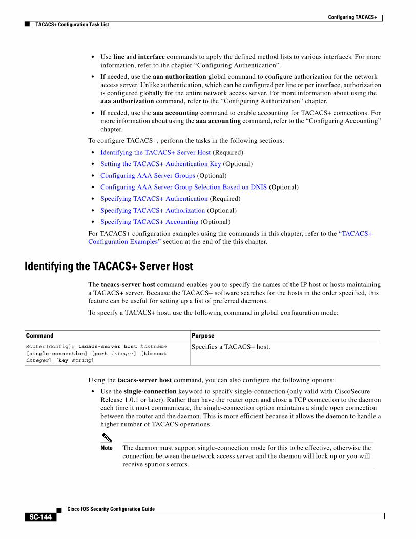
Configuring TACACS+TACACS+ Configuration Task List
SC-144Cisco IOS Security Configuration Guide
• Use line and interface commands to apply the defined method lists to various interfaces. For more information, refer to the chapter “Configuring Authentication”.
• If needed, use the aaa authorization global command to configure authorization for the network access server. Unlike authentication, which can be configured per line or per interface, authorization is configured globally for the entire network access server. For more information about using the aaa authorization command, refer to the “Configuring Authorization” chapter.
• If needed, use the aaa accounting command to enable accounting for TACACS+ connections. For more information about using the aaa accounting command, refer to the “Configuring Accounting” chapter.
To configure TACACS+, perform the tasks in the following sections:
• Identifying the TACACS+ Server Host (Required)
• Setting the TACACS+ Authentication Key (Optional)
• Configuring AAA Server Groups (Optional)
• Configuring AAA Server Group Selection Based on DNIS (Optional)
• Specifying TACACS+ Authentication (Required)
• Specifying TACACS+ Authorization (Optional)
• Specifying TACACS+ Accounting (Optional)
For TACACS+ configuration examples using the commands in this chapter, refer to the “TACACS+ Configuration Examples” section at the end of the this chapter.
Identifying the TACACS+ Server HostThe tacacs-server host command enables you to specify the names of the IP host or hosts maintaining a TACACS+ server. Because the TACACS+ software searches for the hosts in the order specified, this feature can be useful for setting up a list of preferred daemons.
To specify a TACACS+ host, use the following command in global configuration mode:
Using the tacacs-server host command, you can also configure the following options:
• Use the single-connection keyword to specify single-connection (only valid with CiscoSecure Release 1.0.1 or later). Rather than have the router open and close a TCP connection to the daemon each time it must communicate, the single-connection option maintains a single open connection between the router and the daemon. This is more efficient because it allows the daemon to handle a higher number of TACACS operations.
Note The daemon must support single-connection mode for this to be effective, otherwise the connection between the network access server and the daemon will lock up or you will receive spurious errors.
Command PurposeRouter(config)# tacacs-server host hostname [single-connection] [port integer] [timeout integer] [key string]
Specifies a TACACS+ host.
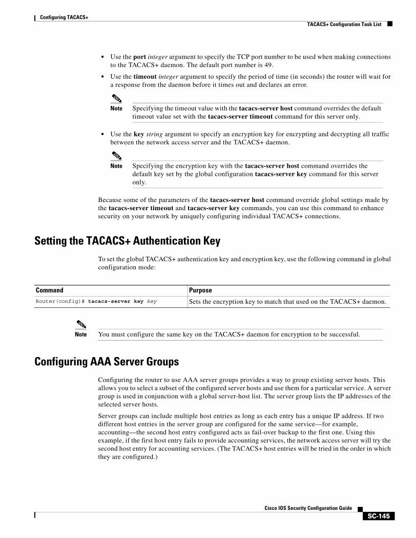
Configuring TACACS+TACACS+ Configuration Task List
SC-145Cisco IOS Security Configuration Guide
• Use the port integer argument to specify the TCP port number to be used when making connections to the TACACS+ daemon. The default port number is 49.
• Use the timeout integer argument to specify the period of time (in seconds) the router will wait for a response from the daemon before it times out and declares an error.
Note Specifying the timeout value with the tacacs-server host command overrides the default timeout value set with the tacacs-server timeout command for this server only.
• Use the key string argument to specify an encryption key for encrypting and decrypting all traffic between the network access server and the TACACS+ daemon.
Note Specifying the encryption key with the tacacs-server host command overrides the default key set by the global configuration tacacs-server key command for this server only.
Because some of the parameters of the tacacs-server host command override global settings made by the tacacs-server timeout and tacacs-server key commands, you can use this command to enhance security on your network by uniquely configuring individual TACACS+ connections.
Setting the TACACS+ Authentication KeyTo set the global TACACS+ authentication key and encryption key, use the following command in global configuration mode:
Note You must configure the same key on the TACACS+ daemon for encryption to be successful.
Configuring AAA Server GroupsConfiguring the router to use AAA server groups provides a way to group existing server hosts. This allows you to select a subset of the configured server hosts and use them for a particular service. A server group is used in conjunction with a global server-host list. The server group lists the IP addresses of the selected server hosts.
Server groups can include multiple host entries as long as each entry has a unique IP address. If two different host entries in the server group are configured for the same service—for example, accounting—the second host entry configured acts as fail-over backup to the first one. Using this example, if the first host entry fails to provide accounting services, the network access server will try the second host entry for accounting services. (The TACACS+ host entries will be tried in the order in which they are configured.)
Command Purpose
Router(config)# tacacs-server key key Sets the encryption key to match that used on the TACACS+ daemon.
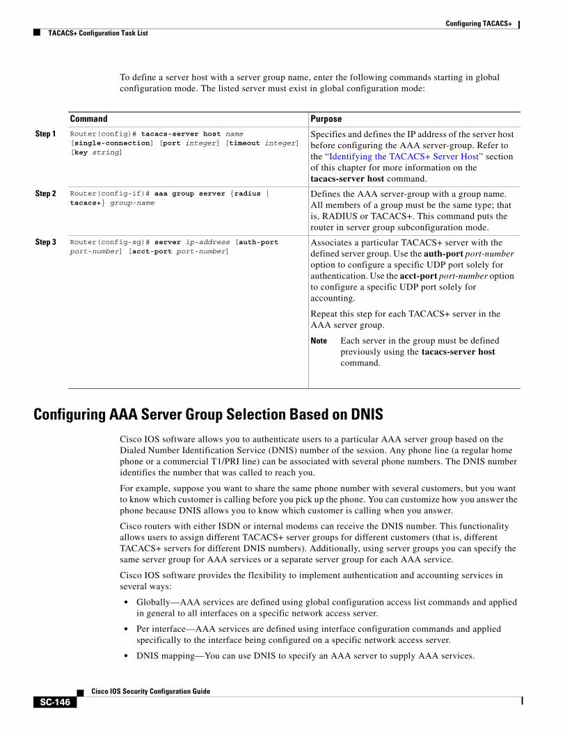
Configuring TACACS+TACACS+ Configuration Task List
SC-146Cisco IOS Security Configuration Guide
To define a server host with a server group name, enter the following commands starting in global configuration mode. The listed server must exist in global configuration mode:
Configuring AAA Server Group Selection Based on DNISCisco IOS software allows you to authenticate users to a particular AAA server group based on the Dialed Number Identification Service (DNIS) number of the session. Any phone line (a regular home phone or a commercial T1/PRI line) can be associated with several phone numbers. The DNIS number identifies the number that was called to reach you.
For example, suppose you want to share the same phone number with several customers, but you want to know which customer is calling before you pick up the phone. You can customize how you answer the phone because DNIS allows you to know which customer is calling when you answer.
Cisco routers with either ISDN or internal modems can receive the DNIS number. This functionality allows users to assign different TACACS+ server groups for different customers (that is, different TACACS+ servers for different DNIS numbers). Additionally, using server groups you can specify the same server group for AAA services or a separate server group for each AAA service.
Cisco IOS software provides the flexibility to implement authentication and accounting services in several ways:
• Globally—AAA services are defined using global configuration access list commands and applied in general to all interfaces on a specific network access server.
• Per interface—AAA services are defined using interface configuration commands and applied specifically to the interface being configured on a specific network access server.
• DNIS mapping—You can use DNIS to specify an AAA server to supply AAA services.
Command Purpose
Step 1 Router(config)# tacacs-server host name [single-connection] [port integer] [timeout integer] [key string]
Specifies and defines the IP address of the server host before configuring the AAA server-group. Refer to the “Identifying the TACACS+ Server Host” section of this chapter for more information on the tacacs-server host command.
Step 2 Router(config-if)# aaa group server {radius | tacacs+} group-name
Defines the AAA server-group with a group name. All members of a group must be the same type; that is, RADIUS or TACACS+. This command puts the router in server group subconfiguration mode.
Step 3 Router(config-sg)# server ip-address [auth-port port-number] [acct-port port-number]
Associates a particular TACACS+ server with the defined server group. Use the auth-port port-number option to configure a specific UDP port solely for authentication. Use the acct-port port-number option to configure a specific UDP port solely for accounting.
Repeat this step for each TACACS+ server in the AAA server group.
Note Each server in the group must be defined previously using the tacacs-server host command.
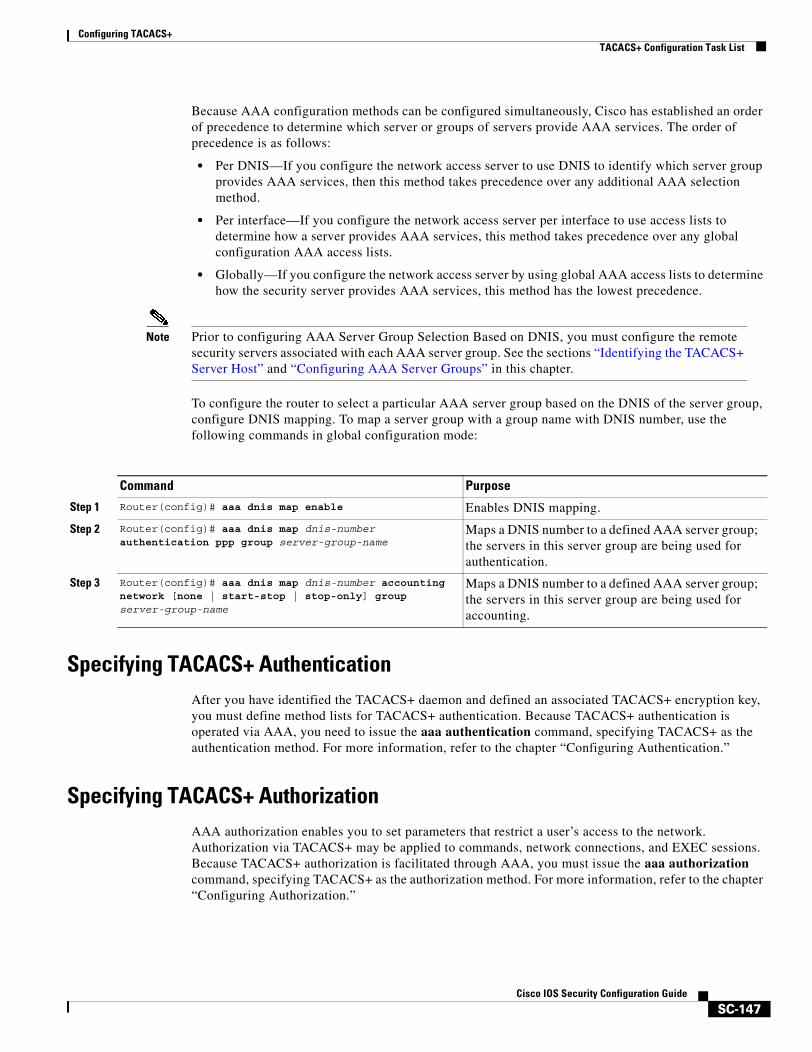
Configuring TACACS+TACACS+ Configuration Task List
SC-147Cisco IOS Security Configuration Guide
Because AAA configuration methods can be configured simultaneously, Cisco has established an order of precedence to determine which server or groups of servers provide AAA services. The order of precedence is as follows:
• Per DNIS—If you configure the network access server to use DNIS to identify which server group provides AAA services, then this method takes precedence over any additional AAA selection method.
• Per interface—If you configure the network access server per interface to use access lists to determine how a server provides AAA services, this method takes precedence over any global configuration AAA access lists.
• Globally—If you configure the network access server by using global AAA access lists to determine how the security server provides AAA services, this method has the lowest precedence.
Note Prior to configuring AAA Server Group Selection Based on DNIS, you must configure the remote security servers associated with each AAA server group. See the sections “Identifying the TACACS+ Server Host” and “Configuring AAA Server Groups” in this chapter.
To configure the router to select a particular AAA server group based on the DNIS of the server group, configure DNIS mapping. To map a server group with a group name with DNIS number, use the following commands in global configuration mode:
Specifying TACACS+ AuthenticationAfter you have identified the TACACS+ daemon and defined an associated TACACS+ encryption key, you must define method lists for TACACS+ authentication. Because TACACS+ authentication is operated via AAA, you need to issue the aaa authentication command, specifying TACACS+ as the authentication method. For more information, refer to the chapter “Configuring Authentication.”
Specifying TACACS+ AuthorizationAAA authorization enables you to set parameters that restrict a user’s access to the network. Authorization via TACACS+ may be applied to commands, network connections, and EXEC sessions. Because TACACS+ authorization is facilitated through AAA, you must issue the aaa authorization command, specifying TACACS+ as the authorization method. For more information, refer to the chapter “Configuring Authorization.”
Command Purpose
Step 1 Router(config)# aaa dnis map enable Enables DNIS mapping.
Step 2 Router(config)# aaa dnis map dnis-number authentication ppp group server-group-name
Maps a DNIS number to a defined AAA server group; the servers in this server group are being used for authentication.
Step 3 Router(config)# aaa dnis map dnis-number accounting network [none | start-stop | stop-only] group server-group-name
Maps a DNIS number to a defined AAA server group; the servers in this server group are being used for accounting.
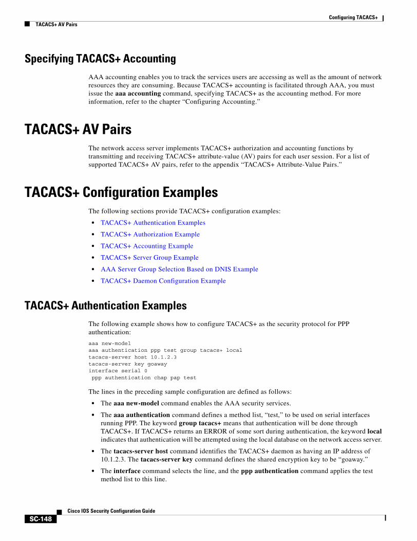
Configuring TACACS+TACACS+ AV Pairs
SC-148Cisco IOS Security Configuration Guide
Specifying TACACS+ AccountingAAA accounting enables you to track the services users are accessing as well as the amount of network resources they are consuming. Because TACACS+ accounting is facilitated through AAA, you must issue the aaa accounting command, specifying TACACS+ as the accounting method. For more information, refer to the chapter “Configuring Accounting.”
TACACS+ AV PairsThe network access server implements TACACS+ authorization and accounting functions by transmitting and receiving TACACS+ attribute-value (AV) pairs for each user session. For a list of supported TACACS+ AV pairs, refer to the appendix “TACACS+ Attribute-Value Pairs.”
TACACS+ Configuration ExamplesThe following sections provide TACACS+ configuration examples:
• TACACS+ Authentication Examples
• TACACS+ Authorization Example
• TACACS+ Accounting Example
• TACACS+ Server Group Example
• AAA Server Group Selection Based on DNIS Example
• TACACS+ Daemon Configuration Example
TACACS+ Authentication ExamplesThe following example shows how to configure TACACS+ as the security protocol for PPP authentication:
aaa new-modelaaa authentication ppp test group tacacs+ localtacacs-server host 10.1.2.3tacacs-server key goawayinterface serial 0ppp authentication chap pap test
The lines in the preceding sample configuration are defined as follows:
• The aaa new-model command enables the AAA security services.
• The aaa authentication command defines a method list, “test,” to be used on serial interfaces running PPP. The keyword group tacacs+ means that authentication will be done through TACACS+. If TACACS+ returns an ERROR of some sort during authentication, the keyword local indicates that authentication will be attempted using the local database on the network access server.
• The tacacs-server host command identifies the TACACS+ daemon as having an IP address of 10.1.2.3. The tacacs-server key command defines the shared encryption key to be “goaway.”
• The interface command selects the line, and the ppp authentication command applies the test method list to this line.

Configuring TACACS+TACACS+ Configuration Examples
SC-149Cisco IOS Security Configuration Guide
The following example shows how to configure TACACS+ as the security protocol for PPP authentication, but instead of the “test” method list, the “default” method list is used.
aaa new-modelaaa authentication ppp default if-needed group tacacs+ localtacacs-server host 10.1.2.3tacacs-server key goawayinterface serial 0ppp authentication default
The lines in the preceding sample configuration are defined as follows:
• The aaa new-model command enables the AAA security services.
• The aaa authentication command defines a method list, “default,” to be used on serial interfaces running PPP. The keyword default means that PPP authentication is applied by default to all interfaces. The if-needed keyword means that if the user has already authenticated by going through the ASCII login procedure, then PPP authentication is not necessary and can be skipped. If authentication is needed, the keyword group tacacs+ means that authentication will be done through TACACS+. If TACACS+ returns an ERROR of some sort during authentication, the keyword local indicates that authentication will be attempted using the local database on the network access server.
• The tacacs-server host command identifies the TACACS+ daemon as having an IP address of 10.1.2.3. The tacacs-server key command defines the shared encryption key to be “goaway.”
• The interface command selects the line, and the ppp authentication command applies the default method list to this line.
The following example shows how to create the same authentication algorithm for PAP, but it calls the method list “MIS-access” instead of “default”:
aaa new-modelaaa authentication pap MIS-access if-needed group tacacs+ localtacacs-server host 10.1.2.3tacacs-server key goawayinterface serial 0ppp authentication pap MIS-access
The lines in the preceding sample configuration are defined as follows:
• The aaa new-model command enables the AAA security services.
• The aaa authentication command defines a method list, “MIS-access,” to be used on serial interfaces running PPP. The method list, “MIS-access,” means that PPP authentication is applied to all interfaces. The if-needed keyword means that if the user has already authenticated by going through the ASCII login procedure, then PPP authentication is not necessary and can be skipped. If authentication is needed, the keyword group tacacs+ means that authentication will be done through TACACS+. If TACACS+ returns an ERROR of some sort during authentication, the keyword local indicates that authentication will be attempted using the local database on the network access server.
• The tacacs-server host command identifies the TACACS+ daemon as having an IP address of 10.1.2.3. The tacacs-server key command defines the shared encryption key to be “goaway.”
• The interface command selects the line, and the ppp authentication command applies the default method list to this line.
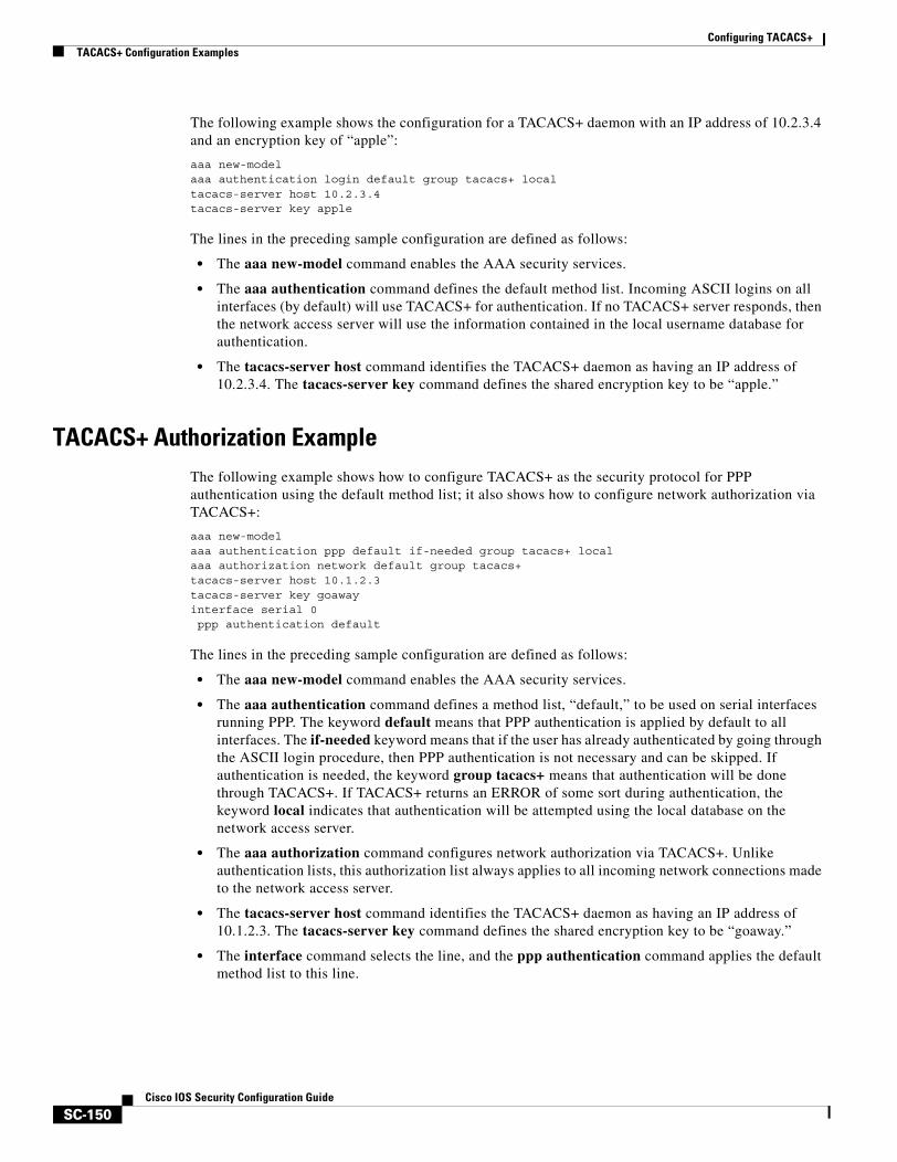
Configuring TACACS+TACACS+ Configuration Examples
SC-150Cisco IOS Security Configuration Guide
The following example shows the configuration for a TACACS+ daemon with an IP address of 10.2.3.4 and an encryption key of “apple”:
aaa new-modelaaa authentication login default group tacacs+ localtacacs-server host 10.2.3.4tacacs-server key apple
The lines in the preceding sample configuration are defined as follows:
• The aaa new-model command enables the AAA security services.
• The aaa authentication command defines the default method list. Incoming ASCII logins on all interfaces (by default) will use TACACS+ for authentication. If no TACACS+ server responds, then the network access server will use the information contained in the local username database for authentication.
• The tacacs-server host command identifies the TACACS+ daemon as having an IP address of 10.2.3.4. The tacacs-server key command defines the shared encryption key to be “apple.”
TACACS+ Authorization ExampleThe following example shows how to configure TACACS+ as the security protocol for PPP authentication using the default method list; it also shows how to configure network authorization via TACACS+:
aaa new-modelaaa authentication ppp default if-needed group tacacs+ localaaa authorization network default group tacacs+tacacs-server host 10.1.2.3tacacs-server key goawayinterface serial 0ppp authentication default
The lines in the preceding sample configuration are defined as follows:
• The aaa new-model command enables the AAA security services.
• The aaa authentication command defines a method list, “default,” to be used on serial interfaces running PPP. The keyword default means that PPP authentication is applied by default to all interfaces. The if-needed keyword means that if the user has already authenticated by going through the ASCII login procedure, then PPP authentication is not necessary and can be skipped. If authentication is needed, the keyword group tacacs+ means that authentication will be done through TACACS+. If TACACS+ returns an ERROR of some sort during authentication, the keyword local indicates that authentication will be attempted using the local database on the network access server.
• The aaa authorization command configures network authorization via TACACS+. Unlike authentication lists, this authorization list always applies to all incoming network connections made to the network access server.
• The tacacs-server host command identifies the TACACS+ daemon as having an IP address of 10.1.2.3. The tacacs-server key command defines the shared encryption key to be “goaway.”
• The interface command selects the line, and the ppp authentication command applies the default method list to this line.
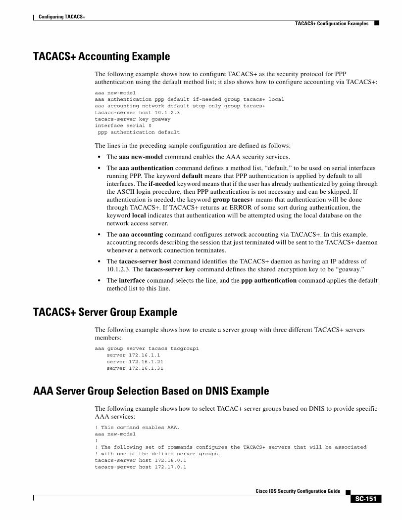
Configuring TACACS+TACACS+ Configuration Examples
SC-151Cisco IOS Security Configuration Guide
TACACS+ Accounting ExampleThe following example shows how to configure TACACS+ as the security protocol for PPP authentication using the default method list; it also shows how to configure accounting via TACACS+:
aaa new-modelaaa authentication ppp default if-needed group tacacs+ localaaa accounting network default stop-only group tacacs+tacacs-server host 10.1.2.3tacacs-server key goawayinterface serial 0ppp authentication default
The lines in the preceding sample configuration are defined as follows:
• The aaa new-model command enables the AAA security services.
• The aaa authentication command defines a method list, “default,” to be used on serial interfaces running PPP. The keyword default means that PPP authentication is applied by default to all interfaces. The if-needed keyword means that if the user has already authenticated by going through the ASCII login procedure, then PPP authentication is not necessary and can be skipped. If authentication is needed, the keyword group tacacs+ means that authentication will be done through TACACS+. If TACACS+ returns an ERROR of some sort during authentication, the keyword local indicates that authentication will be attempted using the local database on the network access server.
• The aaa accounting command configures network accounting via TACACS+. In this example, accounting records describing the session that just terminated will be sent to the TACACS+ daemon whenever a network connection terminates.
• The tacacs-server host command identifies the TACACS+ daemon as having an IP address of 10.1.2.3. The tacacs-server key command defines the shared encryption key to be “goaway.”
• The interface command selects the line, and the ppp authentication command applies the default method list to this line.
TACACS+ Server Group ExampleThe following example shows how to create a server group with three different TACACS+ servers members:
aaa group server tacacs tacgroup1server 172.16.1.1 server 172.16.1.21 server 172.16.1.31
AAA Server Group Selection Based on DNIS ExampleThe following example shows how to select TACAC+ server groups based on DNIS to provide specific AAA services:
! This command enables AAA.aaa new-model!! The following set of commands configures the TACACS+ servers that will be associated! with one of the defined server groups.tacacs-server host 172.16.0.1 tacacs-server host 172.17.0.1
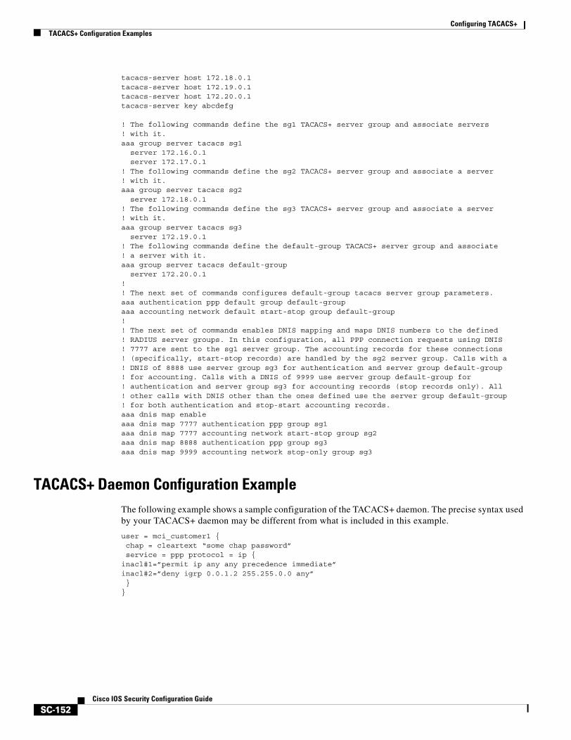
Configuring TACACS+TACACS+ Configuration Examples
SC-152Cisco IOS Security Configuration Guide
tacacs-server host 172.18.0.1 tacacs-server host 172.19.0.1 tacacs-server host 172.20.0.1 tacacs-server key abcdefg
! The following commands define the sg1 TACACS+ server group and associate servers ! with it.aaa group server tacacs sg1
server 172.16.0.1server 172.17.0.1
! The following commands define the sg2 TACACS+ server group and associate a server! with it.aaa group server tacacs sg2
server 172.18.0.1! The following commands define the sg3 TACACS+ server group and associate a server! with it.aaa group server tacacs sg3
server 172.19.0.1! The following commands define the default-group TACACS+ server group and associate! a server with it.aaa group server tacacs default-group
server 172.20.0.1!! The next set of commands configures default-group tacacs server group parameters.aaa authentication ppp default group default-groupaaa accounting network default start-stop group default-group!! The next set of commands enables DNIS mapping and maps DNIS numbers to the defined! RADIUS server groups. In this configuration, all PPP connection requests using DNIS! 7777 are sent to the sg1 server group. The accounting records for these connections! (specifically, start-stop records) are handled by the sg2 server group. Calls with a! DNIS of 8888 use server group sg3 for authentication and server group default-group! for accounting. Calls with a DNIS of 9999 use server group default-group for! authentication and server group sg3 for accounting records (stop records only). All! other calls with DNIS other than the ones defined use the server group default-group! for both authentication and stop-start accounting records.aaa dnis map enableaaa dnis map 7777 authentication ppp group sg1aaa dnis map 7777 accounting network start-stop group sg2aaa dnis map 8888 authentication ppp group sg3aaa dnis map 9999 accounting network stop-only group sg3
TACACS+ Daemon Configuration ExampleThe following example shows a sample configuration of the TACACS+ daemon. The precise syntax used by your TACACS+ daemon may be different from what is included in this example.
user = mci_customer1 {chap = cleartext “some chap password”service = ppp protocol = ip {
inacl#1=”permit ip any any precedence immediate”inacl#2=”deny igrp 0.0.1.2 255.255.0.0 any”}
}
SC-153Cisco IOS Security Configuration Guide
Configuring Kerberos
This chapter describes the Kerberos security system. For a complete description of the Kerberos commands used in this chapter, refer to the “Kerberos Commands” chapter in the Cisco IOS Security Command Reference. To locate documentation of other commands that appear in this chapter, use the command reference master index or search online.
To identify the hardware platform or software image information associated with a feature, use the Feature Navigator on Cisco.com to search for information about the feature, or refer to the software release notes for a specific release. For more information, see the section “Identifying Supported Platforms” in the chapter “Using Cisco IOS Software.”
In This Chapter This chapter includes the following topics and tasks:
• About Kerberos
• Kerberos Client Support Operation
• Kerberos Configuration Task List
• Kerberos Configuration Examples
About KerberosKerberos is a secret-key network authentication protocol, developed at the Massachusetts Institute of Technology (MIT), that uses the Data Encryption Standard (DES) cryptographic algorithm for encryption and authentication. Kerberos was designed to authenticate requests for network resources. Kerberos, like other secret-key systems, is based on the concept of a trusted third party that performs secure verification of users and services. In the Kerberos protocol, this trusted third party is called the key distribution center (KDC).
The primary use of Kerberos is to verify that users and the network services they use are really who and what they claim to be. To accomplish this, a trusted Kerberos server issues tickets to users. These tickets, which have a limited lifespan, are stored in a user’s credential cache and can be used in place of the standard username-and-password authentication mechanism.
The Kerberos credential scheme embodies a concept called “single logon.” This process requires authenticating a user once, and then allows secure authentication (without encrypting another password) wherever that user’s credential is accepted.
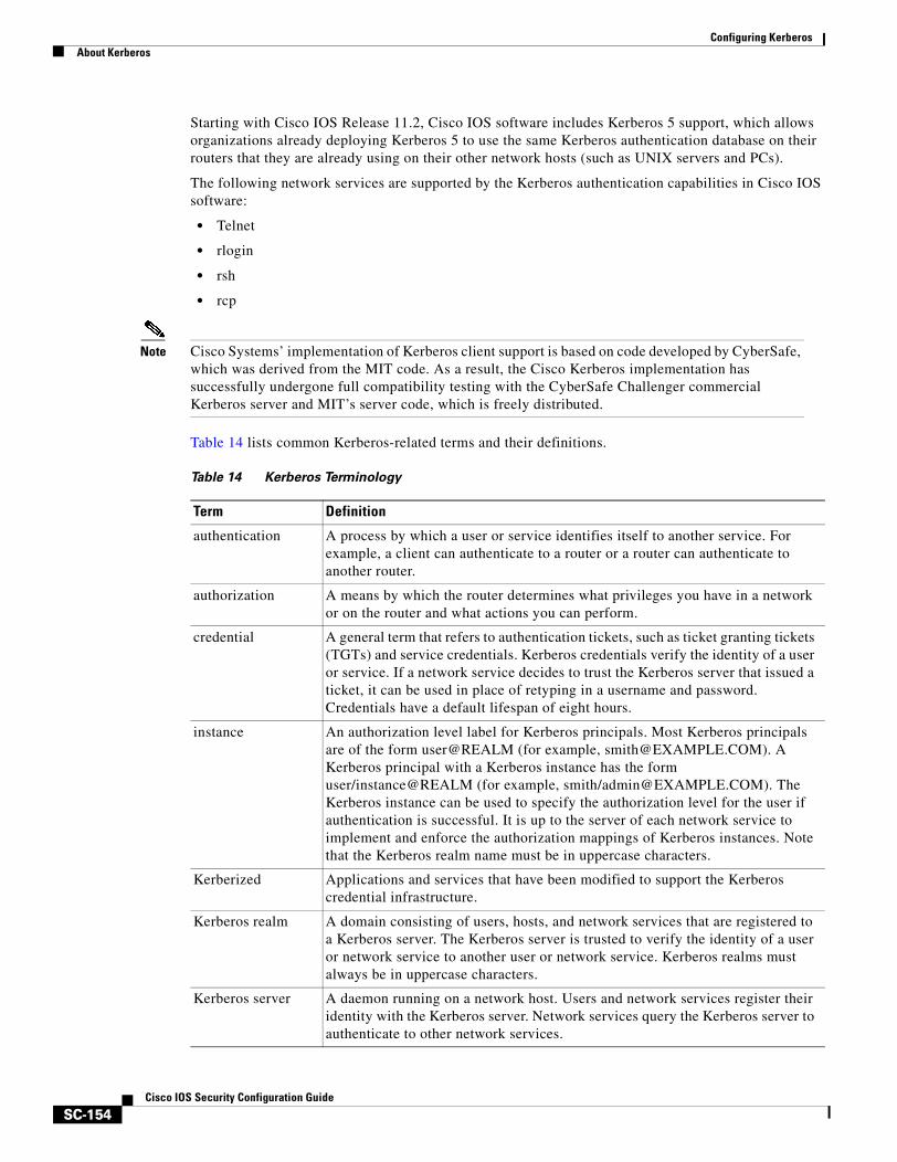
Configuring KerberosAbout Kerberos
SC-154Cisco IOS Security Configuration Guide
Starting with Cisco IOS Release 11.2, Cisco IOS software includes Kerberos 5 support, which allows organizations already deploying Kerberos 5 to use the same Kerberos authentication database on their routers that they are already using on their other network hosts (such as UNIX servers and PCs).
The following network services are supported by the Kerberos authentication capabilities in Cisco IOS software:
• Telnet
• rlogin
• rsh
• rcp
Note Cisco Systems’ implementation of Kerberos client support is based on code developed by CyberSafe, which was derived from the MIT code. As a result, the Cisco Kerberos implementation has successfully undergone full compatibility testing with the CyberSafe Challenger commercial Kerberos server and MIT’s server code, which is freely distributed.
Table 14 lists common Kerberos-related terms and their definitions.
Table 14 Kerberos Terminology
Term Definition
authentication A process by which a user or service identifies itself to another service. For example, a client can authenticate to a router or a router can authenticate to another router.
authorization A means by which the router determines what privileges you have in a network or on the router and what actions you can perform.
credential A general term that refers to authentication tickets, such as ticket granting tickets (TGTs) and service credentials. Kerberos credentials verify the identity of a user or service. If a network service decides to trust the Kerberos server that issued a ticket, it can be used in place of retyping in a username and password. Credentials have a default lifespan of eight hours.
instance An authorization level label for Kerberos principals. Most Kerberos principals are of the form user@REALM (for example, [email protected]). A Kerberos principal with a Kerberos instance has the form user/instance@REALM (for example, smith/[email protected]). The Kerberos instance can be used to specify the authorization level for the user if authentication is successful. It is up to the server of each network service to implement and enforce the authorization mappings of Kerberos instances. Note that the Kerberos realm name must be in uppercase characters.
Kerberized Applications and services that have been modified to support the Kerberos credential infrastructure.
Kerberos realm A domain consisting of users, hosts, and network services that are registered to a Kerberos server. The Kerberos server is trusted to verify the identity of a user or network service to another user or network service. Kerberos realms must always be in uppercase characters.
Kerberos server A daemon running on a network host. Users and network services register their identity with the Kerberos server. Network services query the Kerberos server to authenticate to other network services.
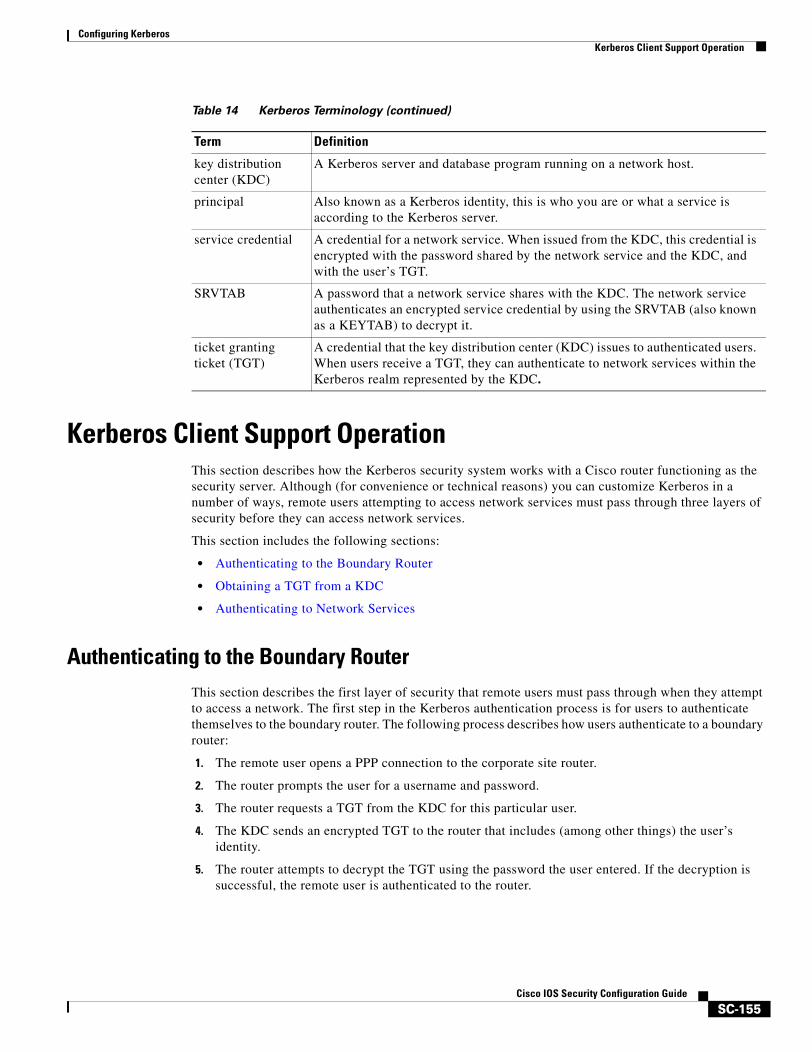
Configuring KerberosKerberos Client Support Operation
SC-155Cisco IOS Security Configuration Guide
Kerberos Client Support OperationThis section describes how the Kerberos security system works with a Cisco router functioning as the security server. Although (for convenience or technical reasons) you can customize Kerberos in a number of ways, remote users attempting to access network services must pass through three layers of security before they can access network services.
This section includes the following sections:
• Authenticating to the Boundary Router
• Obtaining a TGT from a KDC
• Authenticating to Network Services
Authenticating to the Boundary RouterThis section describes the first layer of security that remote users must pass through when they attempt to access a network. The first step in the Kerberos authentication process is for users to authenticate themselves to the boundary router. The following process describes how users authenticate to a boundary router:
1. The remote user opens a PPP connection to the corporate site router.
2. The router prompts the user for a username and password.
3. The router requests a TGT from the KDC for this particular user.
4. The KDC sends an encrypted TGT to the router that includes (among other things) the user’s identity.
5. The router attempts to decrypt the TGT using the password the user entered. If the decryption is successful, the remote user is authenticated to the router.
key distribution center (KDC)
A Kerberos server and database program running on a network host.
principal Also known as a Kerberos identity, this is who you are or what a service is according to the Kerberos server.
service credential A credential for a network service. When issued from the KDC, this credential is encrypted with the password shared by the network service and the KDC, and with the user’s TGT.
SRVTAB A password that a network service shares with the KDC. The network service authenticates an encrypted service credential by using the SRVTAB (also known as a KEYTAB) to decrypt it.
ticket granting ticket (TGT)
A credential that the key distribution center (KDC) issues to authenticated users. When users receive a TGT, they can authenticate to network services within the Kerberos realm represented by the KDC.
Table 14 Kerberos Terminology (continued)
Term Definition
Configuring KerberosKerberos Client Support Operation
SC-156Cisco IOS Security Configuration Guide
A remote user who successfully initiates a PPP session and authenticates to the boundary router is inside the firewall but still must authenticate to the KDC directly before being allowed to access network services. This is because the TGT issued by the KDC is stored on the router and is not useful for additional authentication unless the user physically logs on to the router.
Obtaining a TGT from a KDCThis section describes how remote users who are authenticated to the boundary router authenticate themselves to a KDC.
When a remote user authenticates to a boundary router, that user technically becomes part of the network; that is, the network is extended to include the remote user and the user’s machine or network. To gain access to network services, however, the remote user must obtain a TGT from the KDC. The following process describes how remote users authenticate to the KDC:
1. The remote user, at a workstation on a remote site, launches the KINIT program (part of the client software provided with the Kerberos protocol).
2. The KINIT program finds the user’s identity and requests a TGT from the KDC.
3. The KDC creates a TGT, which contains the identity of the user, the identity of the KDC, and the expiration time of the TGT.
4. Using the user’s password as a key, the KDC encrypts the TGT and sends the TGT to the workstation.
5. When the KINIT program receives the encrypted TGT, it prompts the user for a password (this is the password that is defined for the user in the KDC).
6. If the KINIT program can decrypt the TGT with the password the user enters, the user is authenticated to the KDC, and the KINIT program stores the TGT in the user’s credential cache.
At this point, the user has a TGT and can communicate securely with the KDC. In turn, the TGT allows the user to authenticate to other network services.
Authenticating to Network ServicesThe following process describes how a remote user with a TGT authenticates to network services within a given Kerberos realm. Assume the user is on a remote workstation (Host A) and wants to log in to Host B.
1. The user on Host A initiates a Kerberized application (such as Telnet) to Host B.
2. The Kerberized application builds a service credential request and sends it to the KDC. The service credential request includes (among other things) the user’s identity and the identity of the desired network service. The TGT is used to encrypt the service credential request.
3. The KDC tries to decrypt the service credential request with the TGT it issued to the user on Host A. If the KDC can decrypt the packet, it is assured that the authenticated user on Host A sent the request.
4. The KDC notes the network service identity in the service credential request.
5. The KDC builds a service credential for the appropriate network service on Host B on behalf of the user on Host A. The service credential contains the client’s identity and the desired network service’s identity.
Configuring KerberosKerberos Configuration Task List
SC-157Cisco IOS Security Configuration Guide
6. The KDC then encrypts the service credential twice. It first encrypts the credential with the SRVTAB that it shares with the network service identified in the credential. It then encrypts the resulting packet with the TGT of the user (who, in this case, is on Host A).
7. The KDC sends the twice-encrypted credential to Host A.
8. Host A attempts to decrypt the service credential with the user’s TGT. If Host A can decrypt the service credential, it is assured the credential came from the real KDC.
9. Host A sends the service credential to the desired network service. Note that the credential is still encrypted with the SRVTAB shared by the KDC and the network service.
10. The network service attempts to decrypt the service credential using its SRVTAB.
11. If the network service can decrypt the credential, it is assured the credential was in fact issued from the KDC. Note that the network service trusts anything it can decrypt from the KDC, even if it receives it indirectly from a user. This is because the user first authenticated with the KDC.
At this point, the user is authenticated to the network service on Host B. This process is repeated each time a user wants to access a network service in the Kerberos realm.
Kerberos Configuration Task ListFor hosts and the KDC in your Kerberos realm to communicate and mutually authenticate, you must identify them to each other. To do this, you add entries for the hosts to the Kerberos database on the KDC and add SRVTAB files generated by the KDC to all hosts in the Kerberos realm. You also make entries for users in the KDC database.
This section describes how to set up a Kerberos-authenticated server-client system and contains the following topics:
• Configuring the KDC Using Kerberos Commands
• Configuring the Router to Use the Kerberos Protocol
This section assumes that you have installed the Kerberos administrative programs on a UNIX host, known as the KDC, initialized the database, and selected a Kerberos realm name and password. For instructions about completing these tasks, refer to documentation that came with your Kerberos software.
Note Write down the host name or IP address of the KDC, the port number you want the KDC to monitor for queries, and the name of the Kerberos realm it will serve. You need this information to configure the router.
Configuring the KDC Using Kerberos Commands After you set up a host to function as the KDC in your Kerberos realm, you must make entries to the KDC database for all principals in the realm. Principals can be network services on Cisco routers and hosts or they can be users.
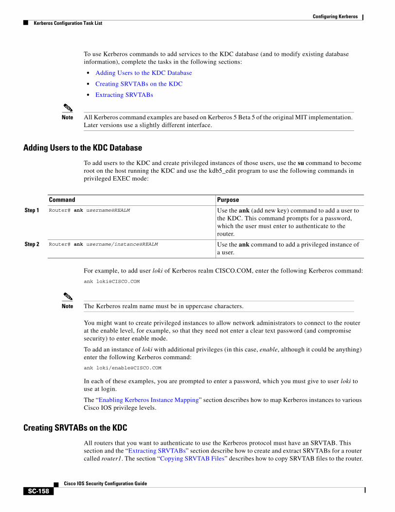
Configuring KerberosKerberos Configuration Task List
SC-158Cisco IOS Security Configuration Guide
To use Kerberos commands to add services to the KDC database (and to modify existing database information), complete the tasks in the following sections:
• Adding Users to the KDC Database
• Creating SRVTABs on the KDC
• Extracting SRVTABs
Note All Kerberos command examples are based on Kerberos 5 Beta 5 of the original MIT implementation. Later versions use a slightly different interface.
Adding Users to the KDC Database
To add users to the KDC and create privileged instances of those users, use the su command to become root on the host running the KDC and use the kdb5_edit program to use the following commands in privileged EXEC mode:
For example, to add user loki of Kerberos realm CISCO.COM, enter the following Kerberos command:
Note The Kerberos realm name must be in uppercase characters.
You might want to create privileged instances to allow network administrators to connect to the router at the enable level, for example, so that they need not enter a clear text password (and compromise security) to enter enable mode.
To add an instance of loki with additional privileges (in this case, enable, although it could be anything) enter the following Kerberos command:
ank loki/[email protected]
In each of these examples, you are prompted to enter a password, which you must give to user loki to use at login.
The “Enabling Kerberos Instance Mapping” section describes how to map Kerberos instances to various Cisco IOS privilege levels.
Creating SRVTABs on the KDC
All routers that you want to authenticate to use the Kerberos protocol must have an SRVTAB. This section and the “Extracting SRVTABs” section describe how to create and extract SRVTABs for a router called router1. The section “Copying SRVTAB Files” describes how to copy SRVTAB files to the router.
Command Purpose
Step 1 Router# ank username@REALM Use the ank (add new key) command to add a user to the KDC. This command prompts for a password, which the user must enter to authenticate to the router.
Step 2 Router# ank username/instance@REALM Use the ank command to add a privileged instance of a user.
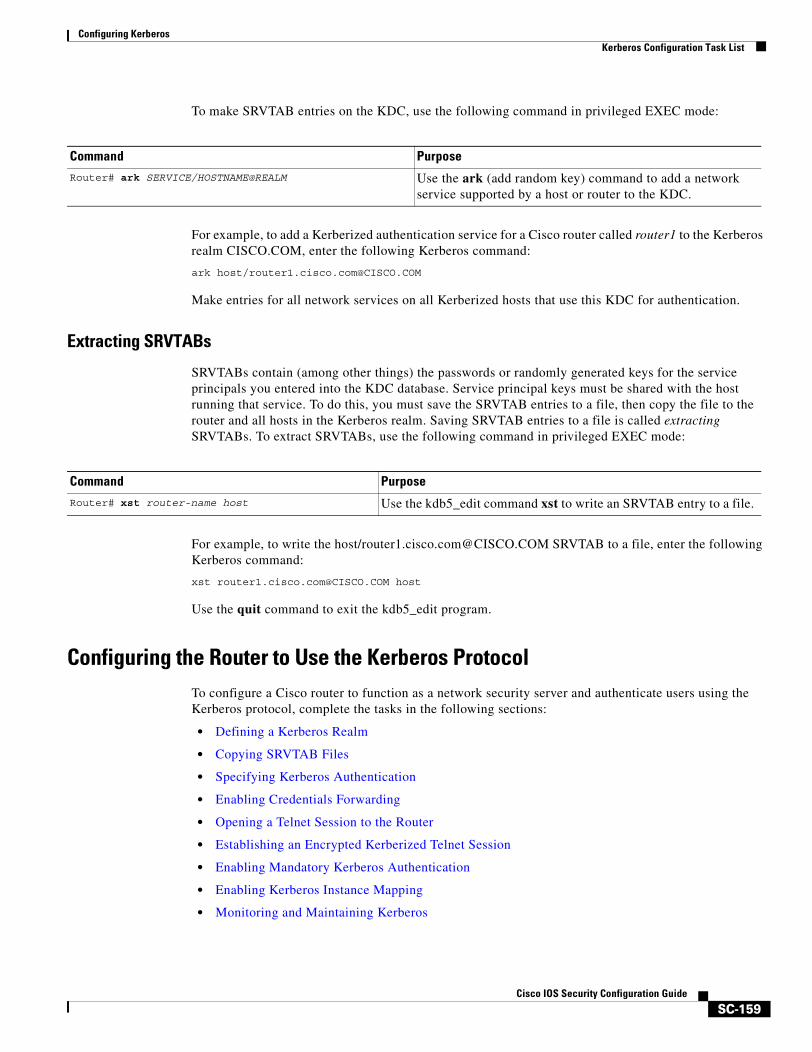
Configuring KerberosKerberos Configuration Task List
SC-159Cisco IOS Security Configuration Guide
To make SRVTAB entries on the KDC, use the following command in privileged EXEC mode:
For example, to add a Kerberized authentication service for a Cisco router called router1 to the Kerberos realm CISCO.COM, enter the following Kerberos command:
ark host/[email protected]
Make entries for all network services on all Kerberized hosts that use this KDC for authentication.
Extracting SRVTABs
SRVTABs contain (among other things) the passwords or randomly generated keys for the service principals you entered into the KDC database. Service principal keys must be shared with the host running that service. To do this, you must save the SRVTAB entries to a file, then copy the file to the router and all hosts in the Kerberos realm. Saving SRVTAB entries to a file is called extracting SRVTABs. To extract SRVTABs, use the following command in privileged EXEC mode:
For example, to write the host/[email protected] SRVTAB to a file, enter the following Kerberos command:
xst [email protected] host
Use the quit command to exit the kdb5_edit program.
Configuring the Router to Use the Kerberos ProtocolTo configure a Cisco router to function as a network security server and authenticate users using the Kerberos protocol, complete the tasks in the following sections:
• Defining a Kerberos Realm
• Copying SRVTAB Files
• Specifying Kerberos Authentication
• Enabling Credentials Forwarding
• Opening a Telnet Session to the Router
• Establishing an Encrypted Kerberized Telnet Session
• Enabling Mandatory Kerberos Authentication
• Enabling Kerberos Instance Mapping
• Monitoring and Maintaining Kerberos
Command PurposeRouter# ark SERVICE/HOSTNAME@REALM Use the ark (add random key) command to add a network
service supported by a host or router to the KDC.
Command Purpose
Router# xst router-name host Use the kdb5_edit command xst to write an SRVTAB entry to a file.
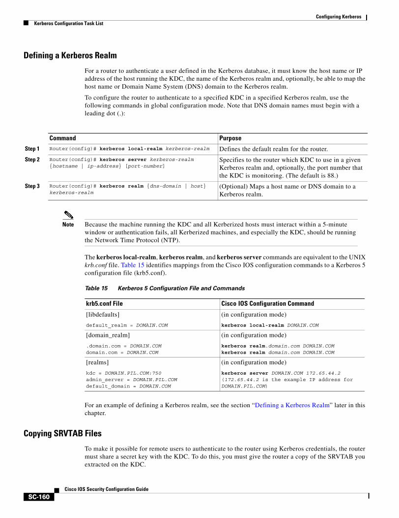
Configuring KerberosKerberos Configuration Task List
SC-160Cisco IOS Security Configuration Guide
Defining a Kerberos Realm
For a router to authenticate a user defined in the Kerberos database, it must know the host name or IP address of the host running the KDC, the name of the Kerberos realm and, optionally, be able to map the host name or Domain Name System (DNS) domain to the Kerberos realm.
To configure the router to authenticate to a specified KDC in a specified Kerberos realm, use the following commands in global configuration mode. Note that DNS domain names must begin with a leading dot (.):
Note Because the machine running the KDC and all Kerberized hosts must interact within a 5-minute window or authentication fails, all Kerberized machines, and especially the KDC, should be running the Network Time Protocol (NTP).
The kerberos local-realm, kerberos realm, and kerberos server commands are equivalent to the UNIX krb.conf file. Table 15 identifies mappings from the Cisco IOS configuration commands to a Kerberos 5 configuration file (krb5.conf).
For an example of defining a Kerberos realm, see the section “Defining a Kerberos Realm” later in this chapter.
Copying SRVTAB Files
To make it possible for remote users to authenticate to the router using Kerberos credentials, the router must share a secret key with the KDC. To do this, you must give the router a copy of the SRVTAB you extracted on the KDC.
Command Purpose
Step 1 Router(config)# kerberos local-realm kerberos-realm Defines the default realm for the router.
Step 2 Router(config)# kerberos server kerberos-realm {hostname | ip-address} [port-number]
Specifies to the router which KDC to use in a given Kerberos realm and, optionally, the port number that the KDC is monitoring. (The default is 88.)
Step 3 Router(config)# kerberos realm {dns-domain | host} kerberos-realm
(Optional) Maps a host name or DNS domain to a Kerberos realm.
Table 15 Kerberos 5 Configuration File and Commands
krb5.conf File Cisco IOS Configuration Command
[libdefaults]
default_realm = DOMAIN.COM
(in configuration mode)
kerberos local-realm DOMAIN.COM
[domain_realm]
.domain.com = DOMAIN.COMdomain.com = DOMAIN.COM
(in configuration mode)
kerberos realm.domain.com DOMAIN.COMkerberos realm domain.com DOMAIN.COM
[realms]
kdc = DOMAIN.PIL.COM:750admin_server = DOMAIN.PIL.COMdefault_domain = DOMAIN.COM
(in configuration mode)
kerberos server DOMAIN.COM 172.65.44.2(172.65.44.2 is the example IP address for DOMAIN.PIL.COM)
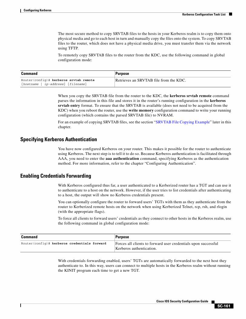
Configuring KerberosKerberos Configuration Task List
SC-161Cisco IOS Security Configuration Guide
The most secure method to copy SRVTAB files to the hosts in your Kerberos realm is to copy them onto physical media and go to each host in turn and manually copy the files onto the system. To copy SRVTAB files to the router, which does not have a physical media drive, you must transfer them via the network using TFTP.
To remotely copy SRVTAB files to the router from the KDC, use the following command in global configuration mode:
When you copy the SRVTAB file from the router to the KDC, the kerberos srvtab remote command parses the information in this file and stores it in the router’s running configuration in the kerberos srvtab entry format. To ensure that the SRVTAB is available (does not need to be acquired from the KDC) when you reboot the router, use the write memory configuration command to write your running configuration (which contains the parsed SRVTAB file) to NVRAM.
For an example of copying SRVTAB files, see the section “SRVTAB File Copying Example” later in this chapter.
Specifying Kerberos Authentication
You have now configured Kerberos on your router. This makes it possible for the router to authenticate using Kerberos. The next step is to tell it to do so. Because Kerberos authentication is facilitated through AAA, you need to enter the aaa authentication command, specifying Kerberos as the authentication method. For more information, refer to the chapter “Configuring Authentication”.
Enabling Credentials Forwarding
With Kerberos configured thus far, a user authenticated to a Kerberized router has a TGT and can use it to authenticate to a host on the network. However, if the user tries to list credentials after authenticating to a host, the output will show no Kerberos credentials present.
You can optionally configure the router to forward users’ TGTs with them as they authenticate from the router to Kerberized remote hosts on the network when using Kerberized Telnet, rcp, rsh, and rlogin (with the appropriate flags).
To force all clients to forward users’ credentials as they connect to other hosts in the Kerberos realm, use the following command in global configuration mode:
With credentials forwarding enabled, users’ TGTs are automatically forwarded to the next host they authenticate to. In this way, users can connect to multiple hosts in the Kerberos realm without running the KINIT program each time to get a new TGT.
Command Purpose
Router(config)# kerberos srvtab remote {hostname | ip-address} {filename}
Retrieves an SRVTAB file from the KDC.
Command PurposeRouter(config)# kerberos credentials forward Forces all clients to forward user credentials upon successful
Kerberos authentication.
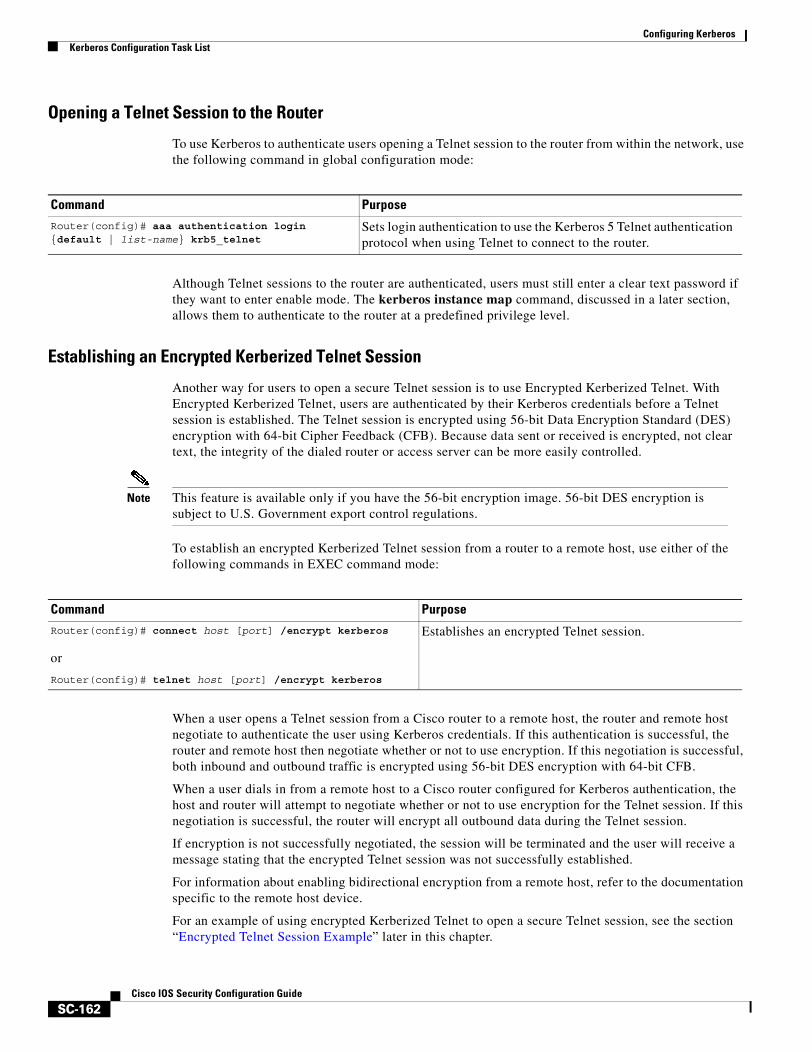
Configuring KerberosKerberos Configuration Task List
SC-162Cisco IOS Security Configuration Guide
Opening a Telnet Session to the Router
To use Kerberos to authenticate users opening a Telnet session to the router from within the network, use the following command in global configuration mode:
Although Telnet sessions to the router are authenticated, users must still enter a clear text password if they want to enter enable mode. The kerberos instance map command, discussed in a later section, allows them to authenticate to the router at a predefined privilege level.
Establishing an Encrypted Kerberized Telnet Session
Another way for users to open a secure Telnet session is to use Encrypted Kerberized Telnet. With Encrypted Kerberized Telnet, users are authenticated by their Kerberos credentials before a Telnet session is established. The Telnet session is encrypted using 56-bit Data Encryption Standard (DES) encryption with 64-bit Cipher Feedback (CFB). Because data sent or received is encrypted, not clear text, the integrity of the dialed router or access server can be more easily controlled.
Note This feature is available only if you have the 56-bit encryption image. 56-bit DES encryption is subject to U.S. Government export control regulations.
To establish an encrypted Kerberized Telnet session from a router to a remote host, use either of the following commands in EXEC command mode:
When a user opens a Telnet session from a Cisco router to a remote host, the router and remote host negotiate to authenticate the user using Kerberos credentials. If this authentication is successful, the router and remote host then negotiate whether or not to use encryption. If this negotiation is successful, both inbound and outbound traffic is encrypted using 56-bit DES encryption with 64-bit CFB.
When a user dials in from a remote host to a Cisco router configured for Kerberos authentication, the host and router will attempt to negotiate whether or not to use encryption for the Telnet session. If this negotiation is successful, the router will encrypt all outbound data during the Telnet session.
If encryption is not successfully negotiated, the session will be terminated and the user will receive a message stating that the encrypted Telnet session was not successfully established.
For information about enabling bidirectional encryption from a remote host, refer to the documentation specific to the remote host device.
For an example of using encrypted Kerberized Telnet to open a secure Telnet session, see the section “Encrypted Telnet Session Example” later in this chapter.
Command PurposeRouter(config)# aaa authentication login {default | list-name} krb5_telnet
Sets login authentication to use the Kerberos 5 Telnet authentication protocol when using Telnet to connect to the router.
Command PurposeRouter(config)# connect host [port] /encrypt kerberos
or
Router(config)# telnet host [port] /encrypt kerberos
Establishes an encrypted Telnet session.

Configuring KerberosKerberos Configuration Task List
SC-163Cisco IOS Security Configuration Guide
Enabling Mandatory Kerberos Authentication
As an added layer of security, you can optionally configure the router so that, after remote users authenticate to it, these users can authenticate to other services on the network only with Kerberized Telnet, rlogin, rsh, and rcp. If you do not make Kerberos authentication mandatory and Kerberos authentication fails, the application attempts to authenticate users using the default method of authentication for that network service; for example, Telnet and rlogin prompt for a password, and rsh attempts to authenticate using the local rhost file.
To make Kerberos authentication mandatory, use the following command in global configuration mode:
Enabling Kerberos Instance Mapping
As mentioned in the section “Creating SRVTABs on the KDC,” you can create administrative instances of users in the KDC database. The kerberos instance map command allows you to map those instances to Cisco IOS privilege levels so that users can open secure Telnet sessions to the router at a predefined privilege level, obviating the need to enter a clear text password to enter enable mode.
To map a Kerberos instance to a Cisco IOS privilege level, use the following command in global configuration mode:
If there is a Kerberos instance for user loki in the KDC database (for example, loki/admin), user loki can now open a Telnet session to the router as loki/admin and authenticate automatically at privilege level 15, assuming instance “admin” is mapped to privilege level 15. (See the section “Adding Users to the KDC Database” earlier in this chapter.)
Cisco IOS commands can be set to various privilege levels using the privilege level command.
After you map a Kerberos instance to a Cisco IOS privilege level, you must configure the router to check for Kerberos instances each time a user logs in. To run authorization to determine if a user is allowed to run an EXEC shell based on a mapped Kerberos instance, use the aaa authorization command with the krb5-instance keyword. For more information, refer to the chapter “Configuring Authorization.”
Command PurposeRouter(config)# kerberos clients mandatory Sets Telnet, rlogin, rsh, and rcp to fail if they cannot negotiate the
Kerberos protocol with the remote server.
Command PurposeRouter(config)# kerberos instance map instance privilege-level
Maps a Kerberos instance to a Cisco IOS privilege level.
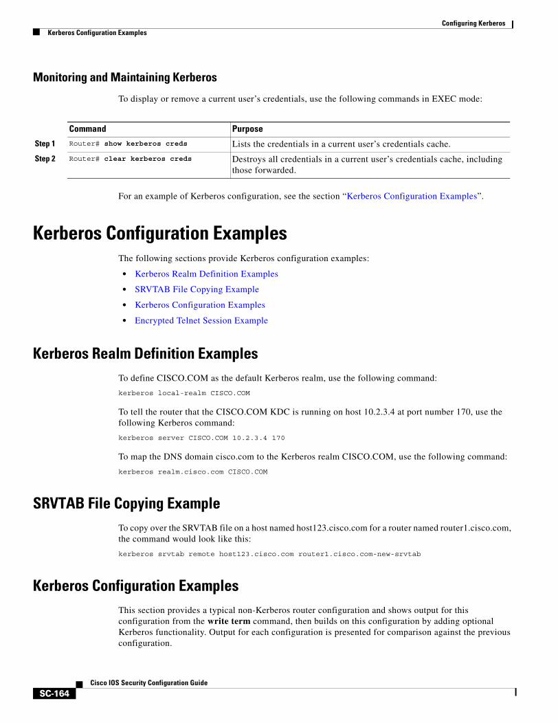
Configuring KerberosKerberos Configuration Examples
SC-164Cisco IOS Security Configuration Guide
Monitoring and Maintaining Kerberos
To display or remove a current user’s credentials, use the following commands in EXEC mode:
For an example of Kerberos configuration, see the section “Kerberos Configuration Examples”.
Kerberos Configuration ExamplesThe following sections provide Kerberos configuration examples:
• Kerberos Realm Definition Examples
• SRVTAB File Copying Example
• Kerberos Configuration Examples
• Encrypted Telnet Session Example
Kerberos Realm Definition ExamplesTo define CISCO.COM as the default Kerberos realm, use the following command:
kerberos local-realm CISCO.COM
To tell the router that the CISCO.COM KDC is running on host 10.2.3.4 at port number 170, use the following Kerberos command:
kerberos server CISCO.COM 10.2.3.4 170
To map the DNS domain cisco.com to the Kerberos realm CISCO.COM, use the following command:
kerberos realm.cisco.com CISCO.COM
SRVTAB File Copying ExampleTo copy over the SRVTAB file on a host named host123.cisco.com for a router named router1.cisco.com, the command would look like this:
kerberos srvtab remote host123.cisco.com router1.cisco.com-new-srvtab
Kerberos Configuration ExamplesThis section provides a typical non-Kerberos router configuration and shows output for this configuration from the write term command, then builds on this configuration by adding optional Kerberos functionality. Output for each configuration is presented for comparison against the previous configuration.
Command Purpose
Step 1 Router# show kerberos creds Lists the credentials in a current user’s credentials cache.
Step 2 Router# clear kerberos creds Destroys all credentials in a current user’s credentials cache, including those forwarded.
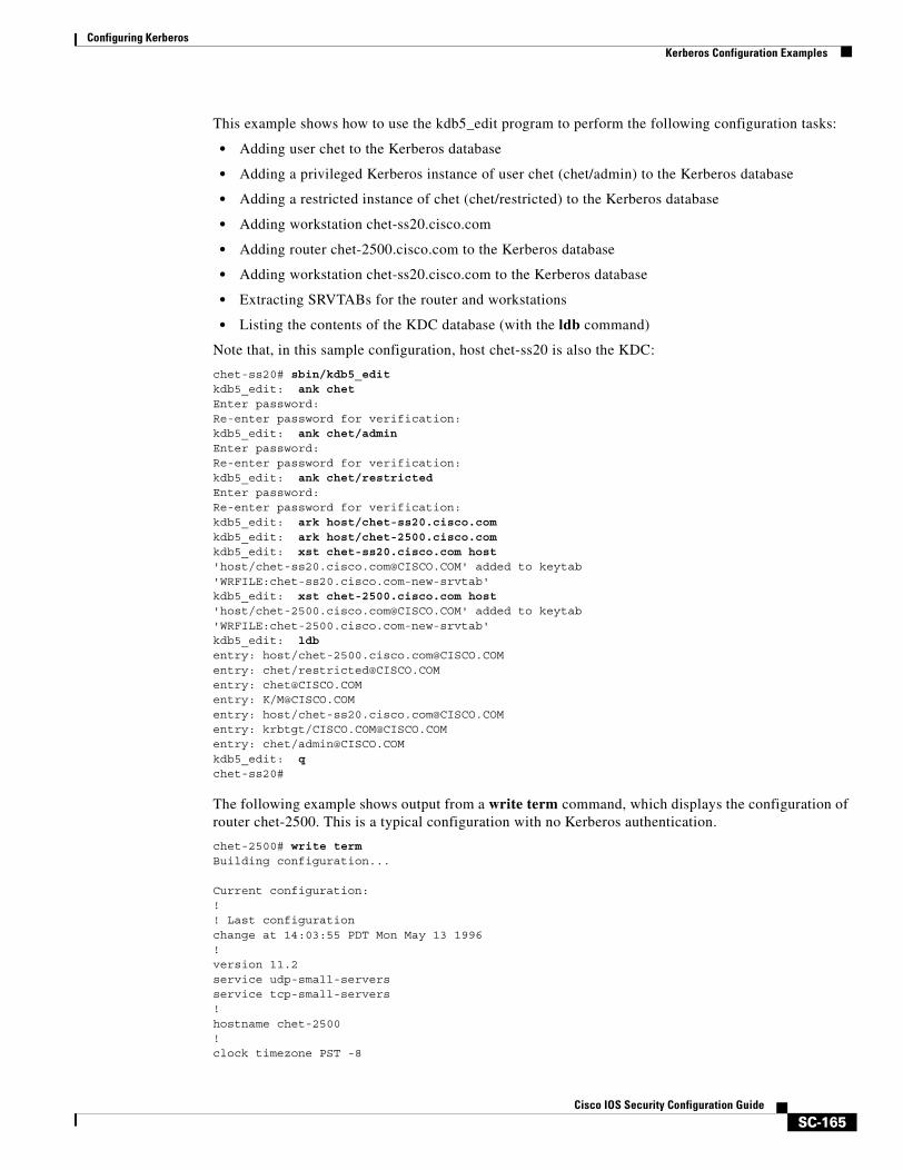
Configuring KerberosKerberos Configuration Examples
SC-165Cisco IOS Security Configuration Guide
This example shows how to use the kdb5_edit program to perform the following configuration tasks:
• Adding user chet to the Kerberos database
• Adding a privileged Kerberos instance of user chet (chet/admin) to the Kerberos database
• Adding a restricted instance of chet (chet/restricted) to the Kerberos database
• Adding workstation chet-ss20.cisco.com
• Adding router chet-2500.cisco.com to the Kerberos database
• Adding workstation chet-ss20.cisco.com to the Kerberos database
• Extracting SRVTABs for the router and workstations
• Listing the contents of the KDC database (with the ldb command)
Note that, in this sample configuration, host chet-ss20 is also the KDC:
chet-ss20# sbin/kdb5_editkdb5_edit: ank chetEnter password:Re-enter password for verification:kdb5_edit: ank chet/adminEnter password:Re-enter password for verification:kdb5_edit: ank chet/restrictedEnter password:Re-enter password for verification:kdb5_edit: ark host/chet-ss20.cisco.comkdb5_edit: ark host/chet-2500.cisco.comkdb5_edit: xst chet-ss20.cisco.com host'host/[email protected]' added to keytab 'WRFILE:chet-ss20.cisco.com-new-srvtab'kdb5_edit: xst chet-2500.cisco.com host'host/[email protected]' added to keytab 'WRFILE:chet-2500.cisco.com-new-srvtab'kdb5_edit: ldbentry: host/[email protected]: chet/[email protected]: [email protected]: K/[email protected]: host/[email protected]: krbtgt/[email protected]: chet/[email protected]_edit: qchet-ss20#
The following example shows output from a write term command, which displays the configuration of router chet-2500. This is a typical configuration with no Kerberos authentication.
chet-2500# write termBuilding configuration...
Current configuration:!! Last configuration change at 14:03:55 PDT Mon May 13 1996!version 11.2service udp-small-serversservice tcp-small-servers!hostname chet-2500!clock timezone PST -8
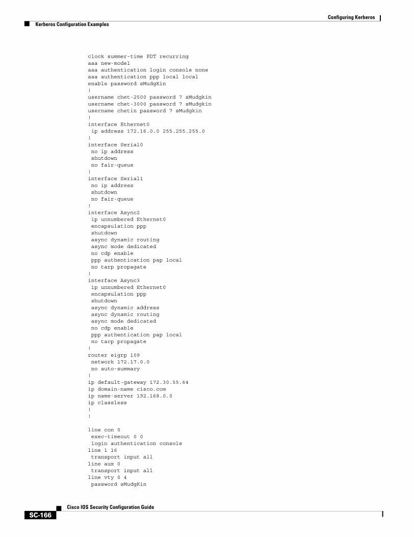
Configuring KerberosKerberos Configuration Examples
SC-166Cisco IOS Security Configuration Guide
clock summer-time PDT recurringaaa new-modelaaa authentication login console noneaaa authentication ppp local localenable password sMudgKin!username chet-2500 password 7 sMudgkinusername chet-3000 password 7 sMudgkinusername chetin password 7 sMudgkin!interface Ethernet0 ip address 172.16.0.0 255.255.255.0!interface Serial0 no ip address shutdown no fair-queue!interface Serial1 no ip address shutdown no fair-queue!interface Async2 ip unnumbered Ethernet0 encapsulation ppp shutdown async dynamic routing async mode dedicated no cdp enable ppp authentication pap local no tarp propagate!interface Async3 ip unnumbered Ethernet0 encapsulation ppp shutdown async dynamic address async dynamic routing async mode dedicated no cdp enable ppp authentication pap local no tarp propagate!router eigrp 109 network 172.17.0.0 no auto-summary!ip default-gateway 172.30.55.64ip domain-name cisco.comip name-server 192.168.0.0ip classless!!
line con 0 exec-timeout 0 0 login authentication consoleline 1 16 transport input allline aux 0 transport input allline vty 0 4 password sMudgKin
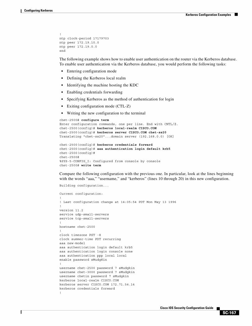
Configuring KerberosKerberos Configuration Examples
SC-167Cisco IOS Security Configuration Guide
!ntp clock-period 17179703ntp peer 172.19.10.0ntp peer 172.19.0.0end
The following example shows how to enable user authentication on the router via the Kerberos database. To enable user authentication via the Kerberos database, you would perform the following tasks:
• Entering configuration mode
• Defining the Kerberos local realm
• Identifying the machine hosting the KDC
• Enabling credentials forwarding
• Specifying Kerberos as the method of authentication for login
• Exiting configuration mode (CTL-Z)
• Writing the new configuration to the terminal
chet-2500# configure termEnter configuration commands, one per line. End with CNTL/Z.chet-2500(config)# kerberos local-realm CISCO.COMchet-2500(config)# kerberos server CISCO.COM chet-ss20Translating "chet-ss20"...domain server (192.168.0.0) [OK]
chet-2500(config)# kerberos credentials forward chet-2500(config)# aaa authentication login default krb5chet-2500(config)#chet-2500#%SYS-5-CONFIG_I: Configured from console by consolechet-2500# write term
Compare the following configuration with the previous one. In particular, look at the lines beginning with the words “aaa,” “username,” and “kerberos” (lines 10 through 20) in this new configuration.
Building configuration...
Current configuration:!! Last configuration change at 14:05:54 PDT Mon May 13 1996!version 11.2service udp-small-serversservice tcp-small-servers!hostname chet-2500!clock timezone PST -8clock summer-time PDT recurringaaa new-modelaaa authentication login default krb5aaa authentication login console noneaaa authentication ppp local localenable password sMudgKin!username chet-2500 password 7 sMudgkinusername chet-3000 password 7 sMudgkinusername chetin password 7 sMudgkinkerberos local-realm CISCO.COMkerberos server CISCO.COM 172.71.54.14kerberos credentials forward!
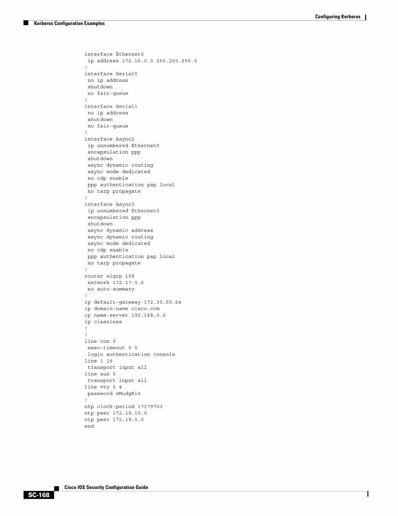
Configuring KerberosKerberos Configuration Examples
SC-168Cisco IOS Security Configuration Guide
interface Ethernet0 ip address 172.16.0.0 255.255.255.0!interface Serial0 no ip address shutdown no fair-queue!interface Serial1 no ip address shutdown no fair-queue!interface Async2 ip unnumbered Ethernet0 encapsulation ppp shutdown async dynamic routing async mode dedicated no cdp enable ppp authentication pap local no tarp propagate!interface Async3 ip unnumbered Ethernet0 encapsulation ppp shutdown async dynamic address async dynamic routing async mode dedicated no cdp enable ppp authentication pap local no tarp propagate!router eigrp 109 network 172.17.0.0 no auto-summary!ip default-gateway 172.30.55.64ip domain-name cisco.comip name-server 192.168.0.0ip classless!!line con 0 exec-timeout 0 0 login authentication consoleline 1 16 transport input allline aux 0 transport input allline vty 0 4 password sMudgKin!ntp clock-period 17179703ntp peer 172.19.10.0ntp peer 172.19.0.0end
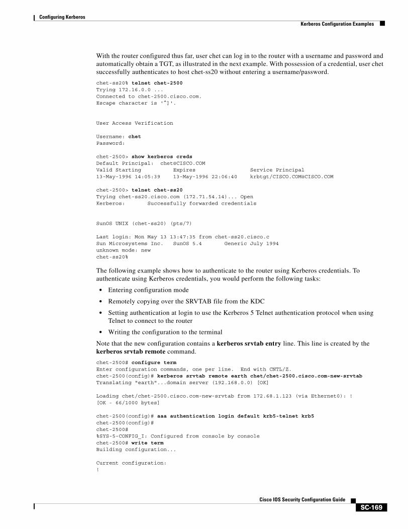
Configuring KerberosKerberos Configuration Examples
SC-169Cisco IOS Security Configuration Guide
With the router configured thus far, user chet can log in to the router with a username and password and automatically obtain a TGT, as illustrated in the next example. With possession of a credential, user chet successfully authenticates to host chet-ss20 without entering a username/password.
chet-ss20% telnet chet-2500Trying 172.16.0.0 ...Connected to chet-2500.cisco.com.Escape character is '^]'.
User Access Verification
Username: chetPassword:
chet-2500> show kerberos creds Default Principal: [email protected] Starting Expires Service Principal13-May-1996 14:05:39 13-May-1996 22:06:40 krbtgt/[email protected]
chet-2500> telnet chet-ss20Trying chet-ss20.cisco.com (172.71.54.14)... OpenKerberos: Successfully forwarded credentials
SunOS UNIX (chet-ss20) (pts/7)
Last login: Mon May 13 13:47:35 from chet-ss20.cisco.cSun Microsystems Inc. SunOS 5.4 Generic July 1994unknown mode: newchet-ss20%
The following example shows how to authenticate to the router using Kerberos credentials. To authenticate using Kerberos credentials, you would perform the following tasks:
• Entering configuration mode
• Remotely copying over the SRVTAB file from the KDC
• Setting authentication at login to use the Kerberos 5 Telnet authentication protocol when using Telnet to connect to the router
• Writing the configuration to the terminal
Note that the new configuration contains a kerberos srvtab entry line. This line is created by the kerberos srvtab remote command.
chet-2500# configure termEnter configuration commands, one per line. End with CNTL/Z.chet-2500(config)# kerberos srvtab remote earth chet/chet-2500.cisco.com-new-srvtabTranslating "earth"...domain server (192.168.0.0) [OK]
Loading chet/chet-2500.cisco.com-new-srvtab from 172.68.1.123 (via Ethernet0): ![OK - 66/1000 bytes]
chet-2500(config)# aaa authentication login default krb5-telnet krb5 chet-2500(config)#chet-2500#%SYS-5-CONFIG_I: Configured from console by consolechet-2500# write termBuilding configuration...
Current configuration:!
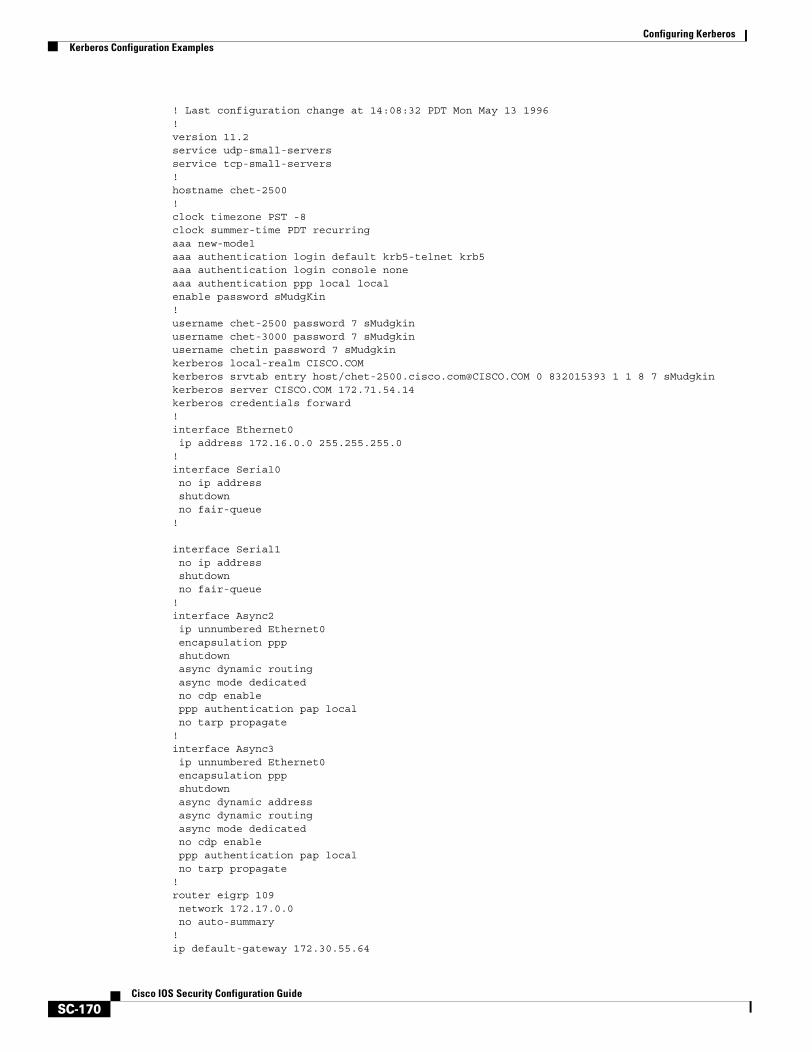
Configuring KerberosKerberos Configuration Examples
SC-170Cisco IOS Security Configuration Guide
! Last configuration change at 14:08:32 PDT Mon May 13 1996!version 11.2service udp-small-serversservice tcp-small-servers!hostname chet-2500!clock timezone PST -8clock summer-time PDT recurringaaa new-modelaaa authentication login default krb5-telnet krb5aaa authentication login console noneaaa authentication ppp local localenable password sMudgKin!username chet-2500 password 7 sMudgkinusername chet-3000 password 7 sMudgkinusername chetin password 7 sMudgkinkerberos local-realm CISCO.COMkerberos srvtab entry host/[email protected] 0 832015393 1 1 8 7 sMudgkinkerberos server CISCO.COM 172.71.54.14kerberos credentials forward!interface Ethernet0 ip address 172.16.0.0 255.255.255.0!interface Serial0 no ip address shutdown no fair-queue!
interface Serial1 no ip address shutdown no fair-queue!interface Async2 ip unnumbered Ethernet0 encapsulation ppp shutdown async dynamic routing async mode dedicated no cdp enable ppp authentication pap local no tarp propagate!interface Async3 ip unnumbered Ethernet0 encapsulation ppp shutdown async dynamic address async dynamic routing async mode dedicated no cdp enable ppp authentication pap local no tarp propagate!router eigrp 109 network 172.17.0.0 no auto-summary!ip default-gateway 172.30.55.64
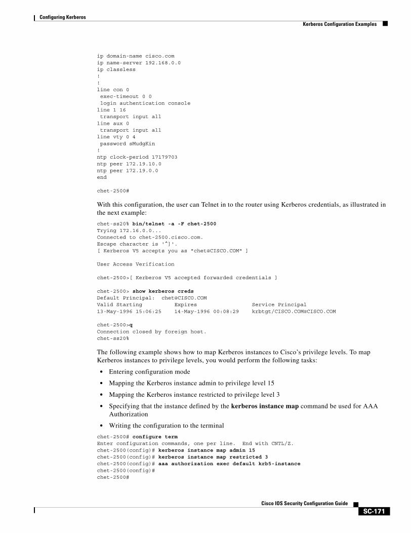
Configuring KerberosKerberos Configuration Examples
SC-171Cisco IOS Security Configuration Guide
ip domain-name cisco.comip name-server 192.168.0.0ip classless!!line con 0 exec-timeout 0 0 login authentication consoleline 1 16 transport input allline aux 0 transport input allline vty 0 4 password sMudgKin!ntp clock-period 17179703ntp peer 172.19.10.0ntp peer 172.19.0.0end
chet-2500#
With this configuration, the user can Telnet in to the router using Kerberos credentials, as illustrated in the next example:
chet-ss20% bin/telnet -a -F chet-2500Trying 172.16.0.0...Connected to chet-2500.cisco.com.Escape character is '^]'.[ Kerberos V5 accepts you as "[email protected]" ]
User Access Verification
chet-2500>[ Kerberos V5 accepted forwarded credentials ]
chet-2500> show kerberos credsDefault Principal: [email protected] Starting Expires Service Principal13-May-1996 15:06:25 14-May-1996 00:08:29 krbtgt/[email protected]
chet-2500>qConnection closed by foreign host.chet-ss20%
The following example shows how to map Kerberos instances to Cisco’s privilege levels. To map Kerberos instances to privilege levels, you would perform the following tasks:
• Entering configuration mode
• Mapping the Kerberos instance admin to privilege level 15
• Mapping the Kerberos instance restricted to privilege level 3
• Specifying that the instance defined by the kerberos instance map command be used for AAA Authorization
• Writing the configuration to the terminal
chet-2500# configure termEnter configuration commands, one per line. End with CNTL/Z.chet-2500(config)# kerberos instance map admin 15chet-2500(config)# kerberos instance map restricted 3chet-2500(config)# aaa authorization exec default krb5-instancechet-2500(config)#chet-2500#
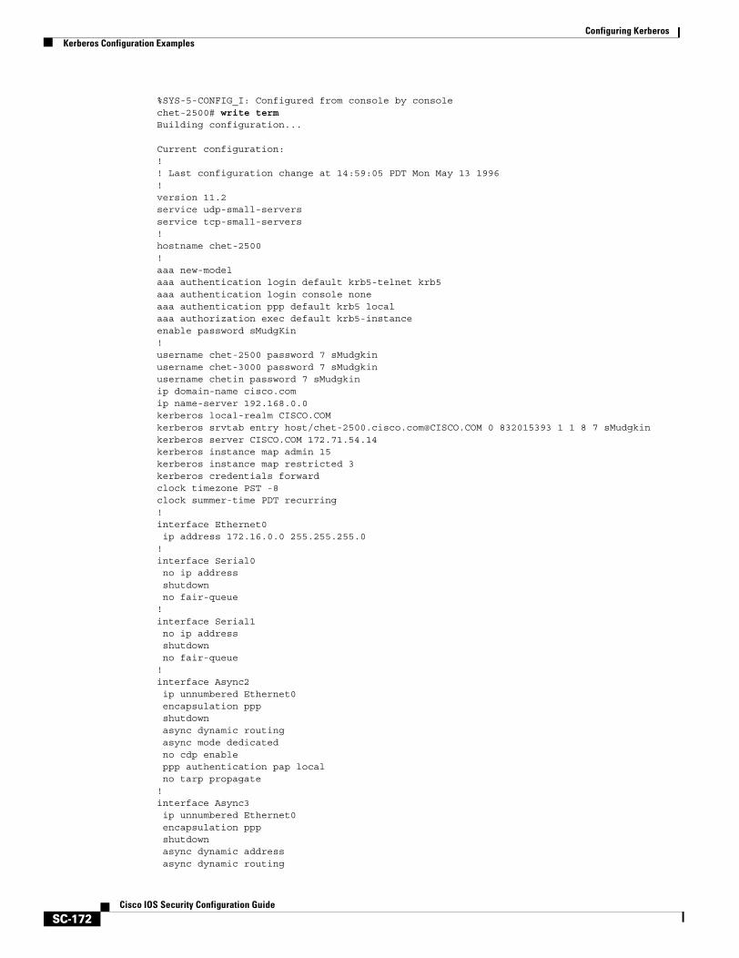
Configuring KerberosKerberos Configuration Examples
SC-172Cisco IOS Security Configuration Guide
%SYS-5-CONFIG_I: Configured from console by consolechet-2500# write termBuilding configuration...
Current configuration:!! Last configuration change at 14:59:05 PDT Mon May 13 1996!version 11.2service udp-small-serversservice tcp-small-servers!hostname chet-2500!aaa new-modelaaa authentication login default krb5-telnet krb5aaa authentication login console noneaaa authentication ppp default krb5 localaaa authorization exec default krb5-instanceenable password sMudgKin!username chet-2500 password 7 sMudgkinusername chet-3000 password 7 sMudgkinusername chetin password 7 sMudgkinip domain-name cisco.comip name-server 192.168.0.0kerberos local-realm CISCO.COMkerberos srvtab entry host/[email protected] 0 832015393 1 1 8 7 sMudgkinkerberos server CISCO.COM 172.71.54.14kerberos instance map admin 15kerberos instance map restricted 3kerberos credentials forwardclock timezone PST -8clock summer-time PDT recurring!interface Ethernet0 ip address 172.16.0.0 255.255.255.0!interface Serial0 no ip address shutdown no fair-queue!interface Serial1 no ip address shutdown no fair-queue!interface Async2 ip unnumbered Ethernet0 encapsulation ppp shutdown async dynamic routing async mode dedicated no cdp enable ppp authentication pap local no tarp propagate!interface Async3 ip unnumbered Ethernet0 encapsulation ppp shutdown async dynamic address async dynamic routing
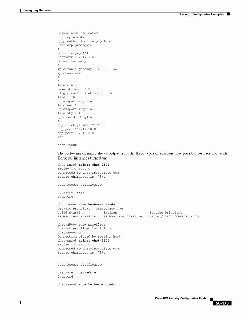
Configuring KerberosKerberos Configuration Examples
SC-173Cisco IOS Security Configuration Guide
async mode dedicated no cdp enable ppp authentication pap local no tarp propagate!router eigrp 109 network 172.17.0.0no auto-summary!ip default-gateway 172.30.55.64ip classless!!line con 0 exec-timeout 0 0 login authentication consoleline 1 16 transport input allline aux 0 transport input allline vty 0 4 password sMudgKin!ntp clock-period 17179703ntp peer 172.19.10.0ntp peer 172.19.0.0end
chet-2500#
The following example shows output from the three types of sessions now possible for user chet with Kerberos instances turned on:
chet-ss20% telnet chet-2500Trying 172.16.0.0 ...Connected to chet-2500.cisco.com.Escape character is '^]'.
User Access Verification
Username: chetPassword:
chet-2500> show kerberos credsDefault Principal: [email protected] Starting Expires Service Principal13-May-1996 14:58:28 13-May-1996 22:59:29 krbtgt/[email protected]
chet-2500> show privilegeCurrent privilege level is 1chet-2500> qConnection closed by foreign host.chet-ss20% telnet chet-2500Trying 172.16.0.0 ...Connected to chet-2500.cisco.com.Escape character is '^]'.
User Access Verification
Username: chet/adminPassword:
chet-2500# show kerberos creds
Configuring KerberosKerberos Configuration Examples
SC-174Cisco IOS Security Configuration Guide
Default Principal: chet/[email protected] Starting Expires Service Principal13-May-1996 14:59:44 13-May-1996 23:00:45 krbtgt/[email protected]# show privilegeCurrent privilege level is 15chet-2500# qConnection closed by foreign host.chet-ss20% telnet chet-2500Trying 172.16.0.0 ...Connected to chet-2500.cisco.com.Escape character is '^]'.
User Access Verification
Username: chet/restrictedPassword:
chet-2500# show kerberos credsDefault Principal: chet/[email protected] Starting Expires Service Principal13-May-1996 15:00:32 13-May-1996 23:01:33 krbtgt/[email protected]
chet-2500# show privilegeCurrent privilege level is 3chet-2500# qConnection closed by foreign host.chet-ss20%
Encrypted Telnet Session ExampleThe following example shows how to establish an encrypted Telnet session from a router to a remote host named “host1”:
Router> telnet host1 /encrypt kerberos

Traffic Filtering and Firewalls

SC-177Cisco IOS Security Configuration Guide
Access Control Lists: Overview and Guidelines
Cisco provides basic traffic filtering capabilities with access control lists (also referred to as access lists). Access lists can be configured for all routed network protocols (IP, AppleTalk, and so on) to filter the packets of those protocols as the packets pass through a router.
You can configure access lists at your router to control access to a network: access lists can prevent certain traffic from entering or exiting a network.
In This ChapterThis chapter describes access lists as part of a security solution. This chapter includes tips, cautions, considerations, recommendations, and general guidelines for how to use access lists.
This chapter has these sections:
• About Access Control Lists
• Overview of Access List Configuration
• Finding Complete Configuration and Command Information for Access Lists
About Access Control ListsThis section briefly describes what access lists do; why and when you should configure access lists; and basic versus advanced access lists.
This section has the following sections:
• What Access Lists Do
• Why You Should Configure Access Lists
• When to Configure Access Lists
• Basic Versus Advanced Access Lists
What Access Lists DoAccess lists filter network traffic by controlling whether routed packets are forwarded or blocked at the router’s interfaces. Your router examines each packet to determine whether to forward or drop the packet, on the basis of the criteria you specified within the access lists.
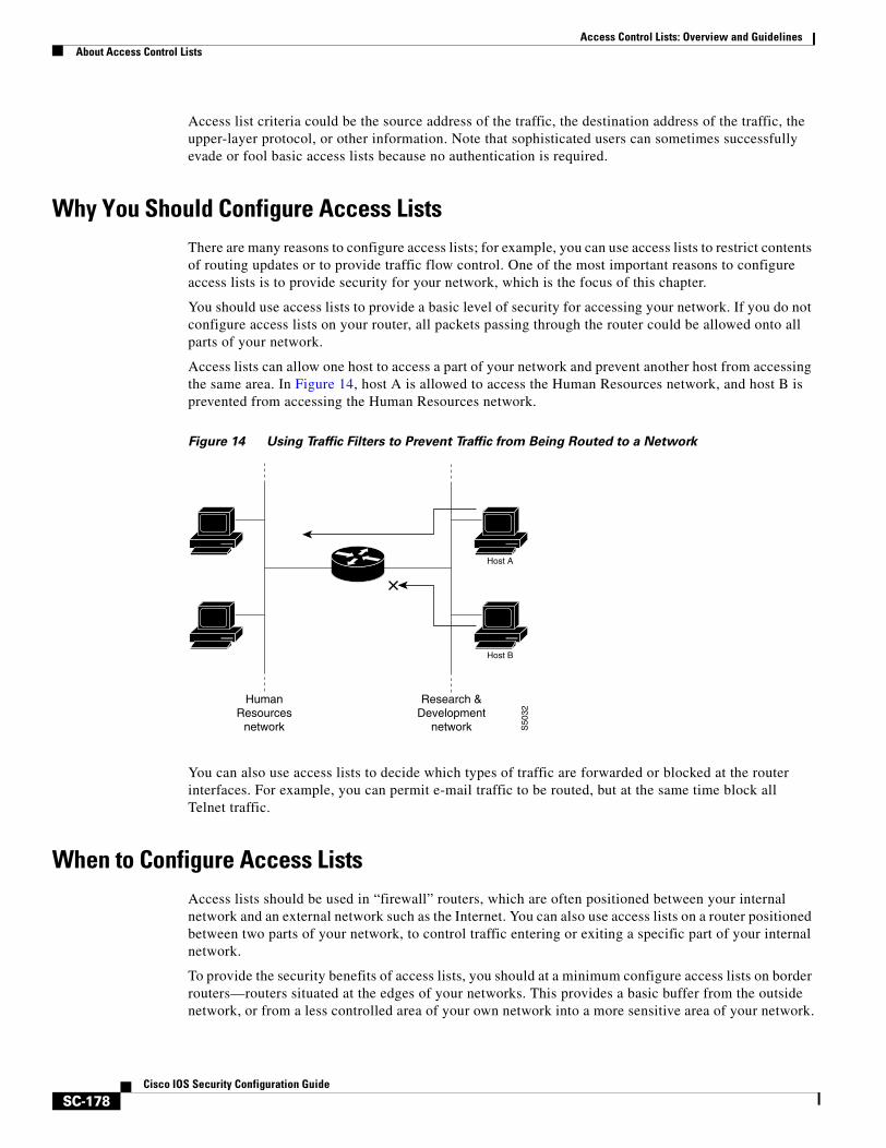
Access Control Lists: Overview and GuidelinesAbout Access Control Lists
SC-178Cisco IOS Security Configuration Guide
Access list criteria could be the source address of the traffic, the destination address of the traffic, the upper-layer protocol, or other information. Note that sophisticated users can sometimes successfully evade or fool basic access lists because no authentication is required.
Why You Should Configure Access ListsThere are many reasons to configure access lists; for example, you can use access lists to restrict contents of routing updates or to provide traffic flow control. One of the most important reasons to configure access lists is to provide security for your network, which is the focus of this chapter.
You should use access lists to provide a basic level of security for accessing your network. If you do not configure access lists on your router, all packets passing through the router could be allowed onto all parts of your network.
Access lists can allow one host to access a part of your network and prevent another host from accessing the same area. In Figure 14, host A is allowed to access the Human Resources network, and host B is prevented from accessing the Human Resources network.
Figure 14 Using Traffic Filters to Prevent Traffic from Being Routed to a Network
You can also use access lists to decide which types of traffic are forwarded or blocked at the router interfaces. For example, you can permit e-mail traffic to be routed, but at the same time block all Telnet traffic.
When to Configure Access ListsAccess lists should be used in “firewall” routers, which are often positioned between your internal network and an external network such as the Internet. You can also use access lists on a router positioned between two parts of your network, to control traffic entering or exiting a specific part of your internal network.
To provide the security benefits of access lists, you should at a minimum configure access lists on border routers—routers situated at the edges of your networks. This provides a basic buffer from the outside network, or from a less controlled area of your own network into a more sensitive area of your network.
Host A
Host B
S50
32
Research &Development
network
HumanResources
network
Access Control Lists: Overview and GuidelinesOverview of Access List Configuration
SC-179Cisco IOS Security Configuration Guide
On these routers, you should configure access lists for each network protocol configured on the router interfaces. You can configure access lists so that inbound traffic or outbound traffic or both are filtered on an interface.
Access lists must be defined on a per-protocol basis. In other words, you should define access lists for every protocol enabled on an interface if you want to control traffic flow for that protocol.
Note Some protocols refer to access lists as filters.
Basic Versus Advanced Access ListsThis chapter describes how to use standard and static extended access lists, which are the basic types of access lists. Some type of basic access list should be used with each routed protocol that you have configured for router interfaces.
Besides the basic types of access lists described in this chapter, there are also more advanced access lists available, which provide additional security features and give you greater control over packet transmission. These advanced access lists and features are described in the other chapters within the part “Traffic Filtering and Firewalls.”
Overview of Access List ConfigurationEach protocol has its own set of specific tasks and rules that are required in order for you to provide traffic filtering. In general, most protocols require at least two basic steps to be accomplished. The first step is to create an access list definition, and the second step is to apply the access list to an interface.
The following sections describe these two steps:
• Creating Access Lists
• Applying Access Lists to Interfaces
Note that some protocols refer to access lists as filters and refer to the act of applying the access lists to interfaces as filtering.
Creating Access ListsCreate access lists for each protocol you wish to filter, per router interface. For some protocols, you create one access list to filter inbound traffic, and one access list to filter outbound traffic.
To create an access list, you specify the protocol to filter, you assign a unique name or number to the access list, and you define packet filtering criteria. A single access list can have multiple filtering criteria statements.
Cisco recommends that you create your access lists on a TFTP server and then download the access lists to your router. This approach can considerably simplify maintenance of your access lists. For details, see the “Creating and Editing Access List Statements on a TFTP Server” section later in this chapter.
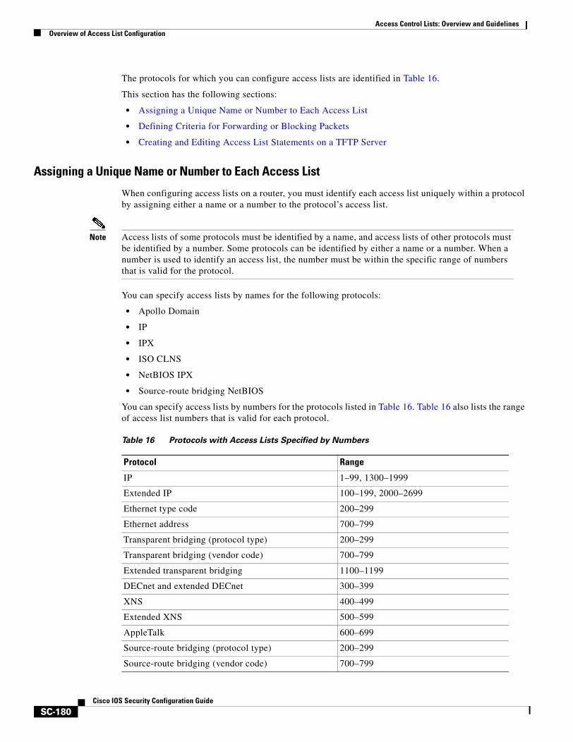
Access Control Lists: Overview and GuidelinesOverview of Access List Configuration
SC-180Cisco IOS Security Configuration Guide
The protocols for which you can configure access lists are identified in Table 16.
This section has the following sections:
• Assigning a Unique Name or Number to Each Access List
• Defining Criteria for Forwarding or Blocking Packets
• Creating and Editing Access List Statements on a TFTP Server
Assigning a Unique Name or Number to Each Access List
When configuring access lists on a router, you must identify each access list uniquely within a protocol by assigning either a name or a number to the protocol’s access list.
Note Access lists of some protocols must be identified by a name, and access lists of other protocols must be identified by a number. Some protocols can be identified by either a name or a number. When a number is used to identify an access list, the number must be within the specific range of numbers that is valid for the protocol.
You can specify access lists by names for the following protocols:
• Apollo Domain
• IP
• IPX
• ISO CLNS
• NetBIOS IPX
• Source-route bridging NetBIOS
You can specify access lists by numbers for the protocols listed in Table 16. Table 16 also lists the range of access list numbers that is valid for each protocol.
Table 16 Protocols with Access Lists Specified by Numbers
Protocol Range
IP 1–99, 1300–1999
Extended IP 100–199, 2000–2699
Ethernet type code 200–299
Ethernet address 700–799
Transparent bridging (protocol type) 200–299
Transparent bridging (vendor code) 700–799
Extended transparent bridging 1100–1199
DECnet and extended DECnet 300–399
XNS 400–499
Extended XNS 500–599
AppleTalk 600–699
Source-route bridging (protocol type) 200–299
Source-route bridging (vendor code) 700–799
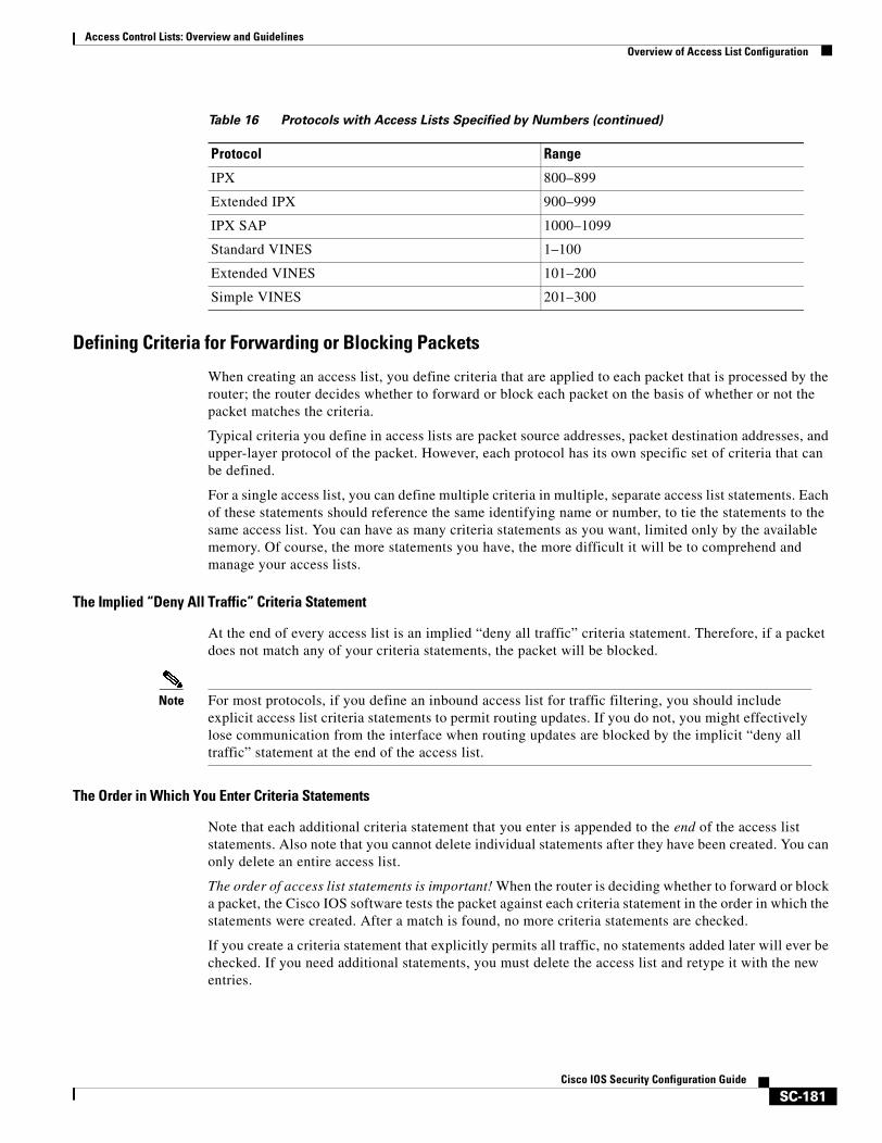
Access Control Lists: Overview and GuidelinesOverview of Access List Configuration
SC-181Cisco IOS Security Configuration Guide
Defining Criteria for Forwarding or Blocking Packets
When creating an access list, you define criteria that are applied to each packet that is processed by the router; the router decides whether to forward or block each packet on the basis of whether or not the packet matches the criteria.
Typical criteria you define in access lists are packet source addresses, packet destination addresses, and upper-layer protocol of the packet. However, each protocol has its own specific set of criteria that can be defined.
For a single access list, you can define multiple criteria in multiple, separate access list statements. Each of these statements should reference the same identifying name or number, to tie the statements to the same access list. You can have as many criteria statements as you want, limited only by the available memory. Of course, the more statements you have, the more difficult it will be to comprehend and manage your access lists.
The Implied “Deny All Traffic” Criteria Statement
At the end of every access list is an implied “deny all traffic” criteria statement. Therefore, if a packet does not match any of your criteria statements, the packet will be blocked.
Note For most protocols, if you define an inbound access list for traffic filtering, you should include explicit access list criteria statements to permit routing updates. If you do not, you might effectively lose communication from the interface when routing updates are blocked by the implicit “deny all traffic” statement at the end of the access list.
The Order in Which You Enter Criteria Statements
Note that each additional criteria statement that you enter is appended to the end of the access list statements. Also note that you cannot delete individual statements after they have been created. You can only delete an entire access list.
The order of access list statements is important! When the router is deciding whether to forward or block a packet, the Cisco IOS software tests the packet against each criteria statement in the order in which the statements were created. After a match is found, no more criteria statements are checked.
If you create a criteria statement that explicitly permits all traffic, no statements added later will ever be checked. If you need additional statements, you must delete the access list and retype it with the new entries.
IPX 800–899
Extended IPX 900–999
IPX SAP 1000–1099
Standard VINES 1–100
Extended VINES 101–200
Simple VINES 201–300
Table 16 Protocols with Access Lists Specified by Numbers (continued)
Protocol Range
Access Control Lists: Overview and GuidelinesFinding Complete Configuration and Command Information for Access Lists
SC-182Cisco IOS Security Configuration Guide
Creating and Editing Access List Statements on a TFTP Server
Because the order of access list criteria statements is important, and because you cannot reorder or delete criteria statements on your router, Cisco recommends that you create all access list statements on a TFTP server, and then download the entire access list to your router.
To use a TFTP server, create the access list statements using any text editor, and save the access list in ASCII format to a TFTP server that is accessible by your router. Then, from your router, use the copy tftp:file_id system:running-config command to copy the access list to your router. Finally, perform the copy system:running-config nvram:startup-config command to save the access list to your router’s NVRAM.
Then, if you ever want to make changes to an access list, you can make them to the text file on the TFTP server, and copy the edited file to your router as before.
Note The first command of an edited access list file should delete the previous access list (for example, type a no access-list command at the beginning of the file). If you do not first delete the previous version of the access list, when you copy the edited file to your router you will merely be appending additional criteria statements to the end of the existing access list.
Applying Access Lists to InterfacesFor some protocols, you can apply up to two access lists to an interface: one inbound access list and one outbound access list. With other protocols, you apply only one access list which checks both inbound and outbound packets.
If the access list is inbound, when the router receives a packet, the Cisco IOS software checks the access list’s criteria statements for a match. If the packet is permitted, the software continues to process the packet. If the packet is denied, the software discards the packet.
If the access list is outbound, after receiving and routing a packet to the outbound interface, the software checks the access list’s criteria statements for a match. If the packet is permitted, the software transmits the packet. If the packet is denied, the software discards the packet.
Finding Complete Configuration and Command Information for Access Lists
The guidelines discussed in this chapter apply in general to all protocols. The specific instructions for creating access lists and applying them to interfaces vary from protocol to protocol, and this specific information is not included in this chapter.
To find complete configuration and command information to configure access lists for a specific protocol, see the corresponding chapters in the Cisco IOS configuration guides and command references. For example, to configure access lists for the IP protocol, refer to the “Configuring IP Services” chapter in the Cisco IOS IP Configuration Guide.
For information on dynamic access lists, see the chapter “Configuring Lock-and-Key Security (Dynamic Access Lists)” later in this book.
For information on reflexive access lists, see the chapter “Configuring IP Session Filtering (Reflexive Access Lists)” later in this book.
SC-183Cisco IOS Security Configuration Guide
Cisco IOS Firewall Overview
This chapter describes how you can configure your Cisco networking device to function as a firewall, using Cisco IOS Firewall security features.
This chapter has the following sections:
• About Firewalls
• The Cisco IOS Firewall Solution
• Creating a Customized Firewall
• Other Guidelines for Configuring Your Firewall
About FirewallsFirewalls are networking devices that control access to your organization’s network assets. Firewalls are positioned at the entrance points into your network. If your network has multiple entrance points, you must position a firewall at each point to provide effective network access control.
Firewalls are often placed in between the internal network and an external network such as the Internet. With a firewall between your network and the Internet, all traffic coming from the Internet must pass through the firewall before entering your network.
Firewalls can also be used to control access to a specific part of your network. For example, you can position firewalls at all the entry points into a research and development network to prevent unauthorized access to proprietary information.
The most basic function of a firewall is to monitor and filter traffic. Firewalls can be simple or elaborate, depending on your network requirements. Simple firewalls are usually easier to configure and manage. However, you might require the flexibility of a more elaborate firewall.
The Cisco IOS Firewall SolutionCisco IOS software provides an extensive set of security features, allowing you to configure a simple or elaborate firewall, according to your particular requirements. You can configure a Cisco device as a firewall if the device is positioned appropriately at a network entry point. Security features that provide firewall functionality are listed in the “Creating a Customized Firewall” section.
In addition to the security features available in standard Cisco IOS feature sets, Cisco IOS Firewall gives your router additional firewall capabilities.
Cisco IOS Firewall OverviewCreating a Customized Firewall
SC-184Cisco IOS Security Configuration Guide
The Cisco IOS Firewall Feature SetThe Cisco IOS Firewall feature set combines existing Cisco IOS firewall technology and the Context-based Access Control (CBAC) feature. When you configure the Cisco IOS Firewall on your Cisco router, you turn your router into an effective, robust firewall.
The Cisco IOS Firewall features are designed to prevent unauthorized external individuals from gaining access to your internal network and to block attacks on your network, while at the same time allowing authorized users to access network resources.
You can use the Cisco IOS Firewall features to configure your Cisco IOS router as one of the following:
• An Internet firewall or part of an Internet firewall
• A firewall between groups in your internal network
• A firewall providing secure connections to or from branch offices
• A firewall between your company’s network and your company’s partners’ networks
The Cisco IOS Firewall features provide the following benefits:
• Protection of internal networks from intrusion
• Monitoring of traffic through network perimeters
• Enabling of network commerce via the World Wide Web
Creating a Customized FirewallTo create a firewall customized to fit your organization’s security policy, you should determine which Cisco IOS Firewall features are appropriate, and configure those features. At a minimum, you must configure basic traffic filtering to provide a basic firewall. You can configure your Cisco networking device to function as a firewall by using the following Cisco IOS Firewall features:
• Standard Access Lists and Static Extended Access Lists
• Lock-and-Key (Dynamic Access Lists)
• Reflexive Access Lists
• TCP Intercept
• Context-based Access Control
• Cisco IOS Firewall Intrusion Detection System
• Authentication Proxy
• Port to Application Mapping
• Security Server Support
• Network Address Translation
• IPSec Network Security
• Neighbor Router Authentication
• Event Logging
• User Authentication and Authorization
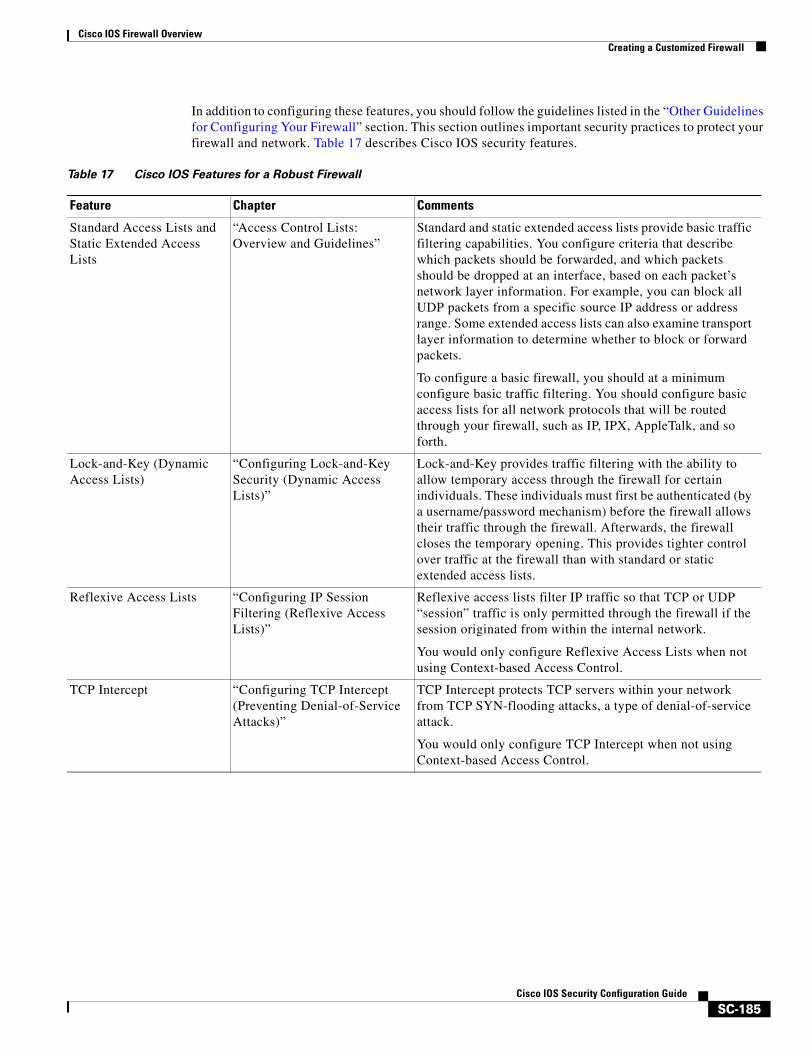
Cisco IOS Firewall OverviewCreating a Customized Firewall
SC-185Cisco IOS Security Configuration Guide
In addition to configuring these features, you should follow the guidelines listed in the “Other Guidelines for Configuring Your Firewall” section. This section outlines important security practices to protect your firewall and network. Table 17 describes Cisco IOS security features.
Table 17 Cisco IOS Features for a Robust Firewall
Feature Chapter Comments
Standard Access Lists and Static Extended Access Lists
“Access Control Lists: Overview and Guidelines”
Standard and static extended access lists provide basic traffic filtering capabilities. You configure criteria that describe which packets should be forwarded, and which packets should be dropped at an interface, based on each packet’s network layer information. For example, you can block all UDP packets from a specific source IP address or address range. Some extended access lists can also examine transport layer information to determine whether to block or forward packets.
To configure a basic firewall, you should at a minimum configure basic traffic filtering. You should configure basic access lists for all network protocols that will be routed through your firewall, such as IP, IPX, AppleTalk, and so forth.
Lock-and-Key (Dynamic Access Lists)
“Configuring Lock-and-Key Security (Dynamic Access Lists)”
Lock-and-Key provides traffic filtering with the ability to allow temporary access through the firewall for certain individuals. These individuals must first be authenticated (by a username/password mechanism) before the firewall allows their traffic through the firewall. Afterwards, the firewall closes the temporary opening. This provides tighter control over traffic at the firewall than with standard or static extended access lists.
Reflexive Access Lists “Configuring IP Session Filtering (Reflexive Access Lists)”
Reflexive access lists filter IP traffic so that TCP or UDP “session” traffic is only permitted through the firewall if the session originated from within the internal network.
You would only configure Reflexive Access Lists when not using Context-based Access Control.
TCP Intercept “Configuring TCP Intercept(Preventing Denial-of-Service Attacks)”
TCP Intercept protects TCP servers within your network from TCP SYN-flooding attacks, a type of denial-of-service attack.
You would only configure TCP Intercept when not using Context-based Access Control.
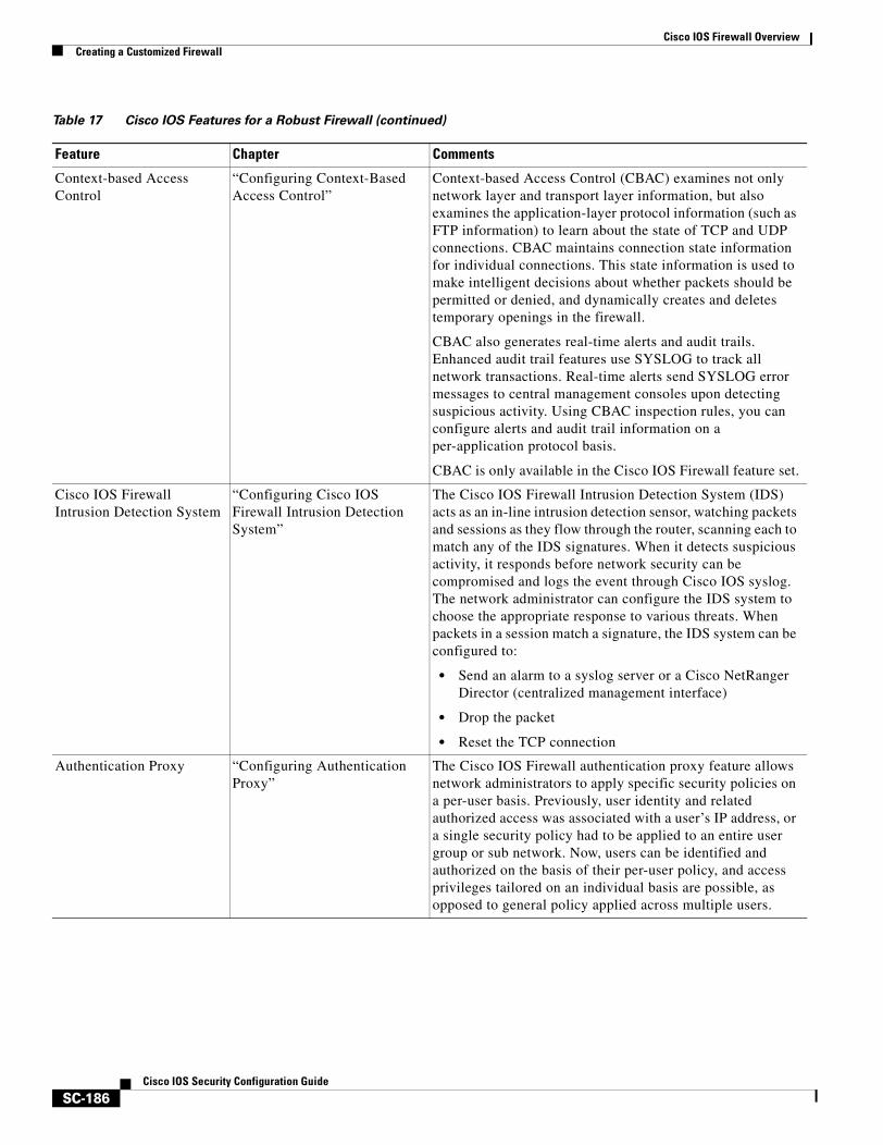
Cisco IOS Firewall OverviewCreating a Customized Firewall
SC-186Cisco IOS Security Configuration Guide
Context-based Access Control
“Configuring Context-Based Access Control”
Context-based Access Control (CBAC) examines not only network layer and transport layer information, but also examines the application-layer protocol information (such as FTP information) to learn about the state of TCP and UDP connections. CBAC maintains connection state information for individual connections. This state information is used to make intelligent decisions about whether packets should be permitted or denied, and dynamically creates and deletes temporary openings in the firewall.
CBAC also generates real-time alerts and audit trails. Enhanced audit trail features use SYSLOG to track all network transactions. Real-time alerts send SYSLOG error messages to central management consoles upon detecting suspicious activity. Using CBAC inspection rules, you can configure alerts and audit trail information on a per-application protocol basis.
CBAC is only available in the Cisco IOS Firewall feature set.
Cisco IOS Firewall Intrusion Detection System
“Configuring Cisco IOS Firewall Intrusion Detection System”
The Cisco IOS Firewall Intrusion Detection System (IDS) acts as an in-line intrusion detection sensor, watching packets and sessions as they flow through the router, scanning each to match any of the IDS signatures. When it detects suspicious activity, it responds before network security can be compromised and logs the event through Cisco IOS syslog. The network administrator can configure the IDS system to choose the appropriate response to various threats. When packets in a session match a signature, the IDS system can be configured to:
• Send an alarm to a syslog server or a Cisco NetRanger Director (centralized management interface)
• Drop the packet
• Reset the TCP connection
Authentication Proxy “Configuring Authentication Proxy”
The Cisco IOS Firewall authentication proxy feature allows network administrators to apply specific security policies on a per-user basis. Previously, user identity and related authorized access was associated with a user’s IP address, or a single security policy had to be applied to an entire user group or sub network. Now, users can be identified and authorized on the basis of their per-user policy, and access privileges tailored on an individual basis are possible, as opposed to general policy applied across multiple users.
Table 17 Cisco IOS Features for a Robust Firewall (continued)
Feature Chapter Comments
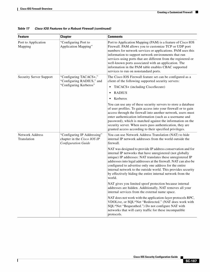
Cisco IOS Firewall OverviewCreating a Customized Firewall
SC-187Cisco IOS Security Configuration Guide
Port to Application Mapping
“Configuring Port to Application Mapping”
Port to Application Mapping (PAM) is a feature of Cisco IOS Firewall. PAM allows you to customize TCP or UDP port numbers for network services or applications. PAM uses this information to support network environments that run services using ports that are different from the registered or well-known ports associated with an application. The information in the PAM table enables CBAC supported services to run on nonstandard ports.
Security Server Support “Configuring TACACS+,” “Configuring RADIUS,” and “Configuring Kerberos”
The Cisco IOS Firewall feature set can be configured as a client of the following supported security servers:
• TACACS+ (including CiscoSecure)
• RADIUS
• Kerberos
You can use any of these security servers to store a database of user profiles. To gain access into your firewall or to gain access through the firewall into another network, users must enter authentication information (such as a username and password), which is matched against the information on the security server. When users pass authentication, they are granted access according to their specified privileges.
Network Address Translation
“Configuring IP Addressing” chapter in the Cisco IOS IP Configuration Guide
You can use Network Address Translation (NAT) to hide internal IP network addresses from the world outside the firewall.
NAT was designed to provide IP address conservation and for internal IP networks that have unregistered (not globally unique) IP addresses: NAT translates these unregistered IP addresses into legal addresses at the firewall. NAT can also be configured to advertise only one address for the entire internal network to the outside world. This provides security by effectively hiding the entire internal network from the world.
NAT gives you limited spoof protection because internal addresses are hidden. Additionally, NAT removes all your internal services from the external name space.
NAT does not work with the application-layer protocols RPC, VDOLive, or SQL*Net “Redirected.” (NAT does work with SQL*Net “Bequeathed.”) Do not configure NAT with networks that will carry traffic for these incompatible protocols.
Table 17 Cisco IOS Features for a Robust Firewall (continued)
Feature Chapter Comments
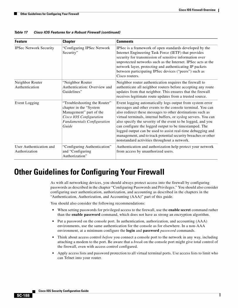
Cisco IOS Firewall OverviewOther Guidelines for Configuring Your Firewall
SC-188Cisco IOS Security Configuration Guide
Other Guidelines for Configuring Your FirewallAs with all networking devices, you should always protect access into the firewall by configuring passwords as described in the chapter “Configuring Passwords and Privileges.” You should also consider configuring user authentication, authorization, and accounting as described in the chapters in the “Authentication, Authorization, and Accounting (AAA)” part of this guide.
You should also consider the following recommendations:
• When setting passwords for privileged access to the firewall, use the enable secret command rather than the enable password command, which does not have as strong an encryption algorithm.
• Put a password on the console port. In authentication, authorization, and accounting (AAA) environments, use the same authentication for the console as for elsewhere. In a non-AAA environment, at a minimum configure the login and password password commands.
• Think about access control before you connect a console port to the network in any way, including attaching a modem to the port. Be aware that a break on the console port might give total control of the firewall, even with access control configured.
• Apply access lists and password protection to all virtual terminal ports. Use access lists to limit who can Telnet into your router.
IPSec Network Security “Configuring IPSec Network Security”
IPSec is a framework of open standards developed by the Internet Engineering Task Force (IETF) that provides security for transmission of sensitive information over unprotected networks such as the Internet. IPSec acts at the network layer, protecting and authenticating IP packets between participating IPSec devices (“peers”) such as Cisco routers.
Neighbor Router Authentication
“Neighbor Router Authentication: Overview and Guidelines”
Neighbor router authentication requires the firewall to authenticate all neighbor routers before accepting any route updates from that neighbor. This ensures that the firewall receives legitimate route updates from a trusted source.
Event Logging “Troubleshooting the Router” chapter in the “System Management” part of the Cisco IOS Configuration Fundamentals Configuration Guide
Event logging automatically logs output from system error messages and other events to the console terminal. You can also redirect these messages to other destinations such as virtual terminals, internal buffers, or syslog servers. You can also specify the severity of the event to be logged, and you can configure the logged output to be timestamped. The logged output can be used to assist real-time debugging and management, and to track potential security breaches or other nonstandard activities throughout a network.
User Authentication and Authorization
“Configuring Authentication” and “Configuring Authorization”
Authentication and authorization help protect your network from access by unauthorized users.
Table 17 Cisco IOS Features for a Robust Firewall (continued)
Feature Chapter Comments

Cisco IOS Firewall OverviewOther Guidelines for Configuring Your Firewall
SC-189Cisco IOS Security Configuration Guide
• Do not enable any local service (such as SNMP or NTP) that you do not use. Cisco Discovery Protocol (CDP) and Network Time Protocol (NTP) are on by default, and you should turn these off if you do not need them.
To turn off CDP, enter the no cdp run global configuration command. To turn off NTP, enter the ntp disable interface configuration command on each interface not using NTP.
If you must run NTP, configure NTP only on required interfaces, and configure NTP to listen only to certain peers.
Any enabled service could present a potential security risk. A determined, hostile party might be able to find creative ways to misuse the enabled services to access the firewall or the network.
For local services that are enabled, protect against misuse. Protect by configuring the services to communicate only with specific peers, and protect by configuring access lists to deny packets for the services at specific interfaces.
• Protect against spoofing: protect the networks on both sides of the firewall from being spoofed from the other side. You could protect against spoofing by configuring input access lists at all interfaces to pass only traffic from expected source addresses, and to deny all other traffic.
You should also disable source routing. For IP, enter the no ip source-route global configuration command. Disabling source routing at all routers can also help prevent spoofing.
You should also disable minor services. For IP, enter the no service tcp-small-servers and no service udp-small-servers global configuration commands.
• Prevent the firewall from being used as a relay by configuring access lists on any asynchronous Telnet ports.
• Normally, you should disable directed broadcasts for all applicable protocols on your firewall and on all your other routers. For IP, use the no ip directed-broadcast command. Rarely, some IP networks do require directed broadcasts; if this is the case, do not disable directed broadcasts.
Directed broadcasts can be misused to multiply the power of denial-of-service attacks, because every denial-of-service packet sent is broadcast to every host on a subnet. Furthermore, some hosts have other intrinsic security risks present when handling broadcasts.
• Configure the no ip proxy-arp command to prevent internal addresses from being revealed. (This is important to do if you do not already have NAT configured to prevent internal addresses from being revealed.)
• Keep the firewall in a secured (locked) room.

Cisco IOS Firewall OverviewOther Guidelines for Configuring Your Firewall
SC-190Cisco IOS Security Configuration Guide
SC-191Cisco IOS Security Configuration Guide
Configuring Lock-and-Key Security (Dynamic Access Lists)
This chapter describes how to configure lock-and-key security at your router. Lock-and-key is a traffic filtering security feature available for the IP protocol.
For a complete description of lock-and-key commands, refer to the “Lock-and-Key Commands” chapter of the Cisco IOS Security Command Reference. To locate documentation of other commands that appear in this chapter, use the command reference master index or search online.
To identify the hardware platform or software image information associated with a feature, use the Feature Navigator on Cisco.com to search for information about the feature or refer to the software release notes for a specific release. For more information, see the chapter “Identifying Supported Platforms” section in the “Using Cisco IOS Software.”
In This ChapterThis chapter has the following sections:
• About Lock-and-Key
• Compatibility with Releases Before Cisco IOS Release 11.1
• Risk of Spoofing with Lock-and-Key
• Router Performance Impacts with Lock-and-Key
• Prerequisites to Configuring Lock-and-Key
• Configuring Lock-and-Key
• Verifying Lock-and-Key Configuration
• Maintaining Lock-and-Key
• Lock-and-Key Configuration Examples
Configuring Lock-and-Key Security (Dynamic Access Lists)About Lock-and-Key
SC-192Cisco IOS Security Configuration Guide
About Lock-and-KeyLock-and-key is a traffic filtering security feature that dynamically filters IP protocol traffic. Lock-and-key is configured using IP dynamic extended access lists. Lock-and-key can be used in conjunction with other standard access lists and static extended access lists.
When lock-and-key is configured, designated users whose IP traffic is normally blocked at a router can gain temporary access through the router. When triggered, lock-and-key reconfigures the interface’s existing IP access list to permit designated users to reach their designated host(s). Afterwards, lock-and-key reconfigures the interface back to its original state.
For a user to gain access to a host through a router with lock-and-key configured, the user must first open a Telnet session to the router. When a user initiates a standard Telnet session to the router, lock-and-key automatically attempts to authenticate the user. If the user is authenticated, they will then gain temporary access through the router and be able to reach their destination host.
This section has the following sections:
• Benefits of Lock-and-Key
• When to Use Lock-and-Key
• How Lock-and-Key Works
Benefits of Lock-and-KeyLock-and-key provides the same benefits as standard and static extended access lists (these benefits are discussed in the chapter “Access Control Lists: Overview and Guidelines”). However, lock-and-key also has the following security benefits over standard and static extended access lists:
• Lock-and-key uses a challenge mechanism to authenticate individual users.
• Lock-and-key provides simpler management in large internetworks.
• In many cases, lock-and-key reduces the amount of router processing required for access lists.
• Lock-and-key reduces the opportunity for network break-ins by network hackers.
With lock-and-key, you can specify which users are permitted access to which source and destination hosts. These users must pass a user authentication process before they are permitted access to their designated hosts. Lock-and-key creates dynamic user access through a firewall, without compromising other configured security restrictions.
When to Use Lock-and-KeyTwo examples of when you might use lock-and-key follow:
• When you want a specific remote user (or group of remote users) to be able to access a host within your network, connecting from their remote hosts via the Internet. Lock-and-key authenticates the user, then permits limited access through your firewall router for the individual’s host or subnet, for a finite period of time.
• When you want a subset of hosts on a local network to access a host on a remote network protected by a firewall. With lock-and-key, you can enable access to the remote host only for the desired set of local user’s hosts. Lock-and-key require the users to authenticate through a TACACS+ server, or other security server, before allowing their hosts to access the remote hosts.
Configuring Lock-and-Key Security (Dynamic Access Lists)Compatibility with Releases Before Cisco IOS Release 11.1
SC-193Cisco IOS Security Configuration Guide
How Lock-and-Key WorksThe following process describes the lock-and-key access operation:
1. A user opens a Telnet session to a border (firewall) router configured for lock-and-key. The user connects via the virtual terminal port on the router.
2. The Cisco IOS software receives the Telnet packet, opens a Telnet session, prompts for a password, and performs a user authentication process. The user must pass authentication before access through the router is allowed. The authentication process can be done by the router or by a central access security server such as a TACACS+ or RADIUS server.
3. When the user passes authentication, they are logged out of the Telnet session, and the software creates a temporary entry in the dynamic access list. (Per your configuration, this temporary entry can limit the range of networks to which the user is given temporary access.)
4. The user exchanges data through the firewall.
5. The software deletes the temporary access list entry when a configured timeout is reached, or when the system administrator manually clears it. The configured timeout can either be an idle timeout or an absolute timeout.
Note The temporary access list entry is not automatically deleted when the user terminates a session. The temporary access list entry remains until a configured timeout is reached or until it is cleared by the system administrator.
Compatibility with Releases Before Cisco IOS Release 11.1Enhancements to the access-list command are used for lock-and-key. These enhancements are backward compatible—if you migrate from a release before Cisco IOS Release 11.1 to a newer release, your access lists will be automatically converted to reflect the enhancements. However, if you try to use lock-and-key with a release before Cisco IOS Release 11.1, you might encounter problems as described in the following caution paragraph:
Caution Cisco IOS releases before Release 11.1 are not upwardly compatible with the lock-and-key access list enhancements. Therefore, if you save an access list with software older than Release 11.1, and then use this software, the resulting access list will not be interpreted correctly. This could cause you severe security problems. You must save your old configuration files with Cisco IOS Release 11.1 or later software before booting an image with these files.
Configuring Lock-and-Key Security (Dynamic Access Lists)Risk of Spoofing with Lock-and-Key
SC-194Cisco IOS Security Configuration Guide
Risk of Spoofing with Lock-and-Key
Caution Lock-and-key access allows an external event (a Telnet session) to place an opening in the firewall. While this opening exists, the router is susceptible to source address spoofing.
When lock-and-key is triggered, it creates a dynamic opening in the firewall by temporarily reconfiguring an interface to allow user access. While this opening exists, another host might spoof the authenticated user’s address to gain access behind the firewall. Lock-and-key does not cause the address spoofing problem; the problem is only identified here as a concern to the user. Spoofing is a problem inherent to all access lists, and lock-and-key does not specifically address this problem.
To prevent spoofing, configure encryption so that traffic from the remote host is encrypted at a secured remote router, and decrypted locally at the router interface providing lock-and-key. You want to ensure that all traffic using lock-and-key will be encrypted when entering the router; this way no hackers can spoof the source address, because they will be unable to duplicate the encryption or to be authenticated as is a required part of the encryption setup process.
Router Performance Impacts with Lock-and-KeyWhen lock-and-key is configured, router performance can be affected in the following ways:
• When lock-and-key is triggered, the dynamic access list forces an access list rebuild on the silicon switching engine (SSE). This causes the SSE switching path to slow down momentarily.
• Dynamic access lists require the idle timeout facility (even if the timeout is left to default) and therefore cannot be SSE switched. These entries must be handled in the protocol fast-switching path.
• When remote users trigger lock-and-key at a border router, additional access list entries are created on the border router interface. The interface’s access list will grow and shrink dynamically. Entries are dynamically removed from the list after either the idle-timeout or max-timeout period expires. Large access lists can degrade packet switching performance, so if you notice performance problems, you should look at the border router configuration to see if you should remove temporary access list entries generated by lock-and-key.
Prerequisites to Configuring Lock-and-KeyLock-and-key uses IP extended access lists. You must have a solid understanding of how access lists are used to filter traffic, before you attempt to configure lock-and-key. Access lists are described in the chapter “Access Control Lists: Overview and Guidelines.”
Lock-and-key employs user authentication and authorization as implemented in Cisco’s authentication, authorization, and accounting (AAA) paradigm. You must understand how to configure AAA user authentication and authorization before you configure lock-and-key. User authentication and authorization is explained in the “Authentication, Authorization, and Accounting (AAA)” part of this document.
Lock-and-key uses the autocommand command, which you should understand. This command is described in the “Modem Support and Asynchronous Device Commands” chapter of the Cisco IOS Dial Technologies Command Reference.
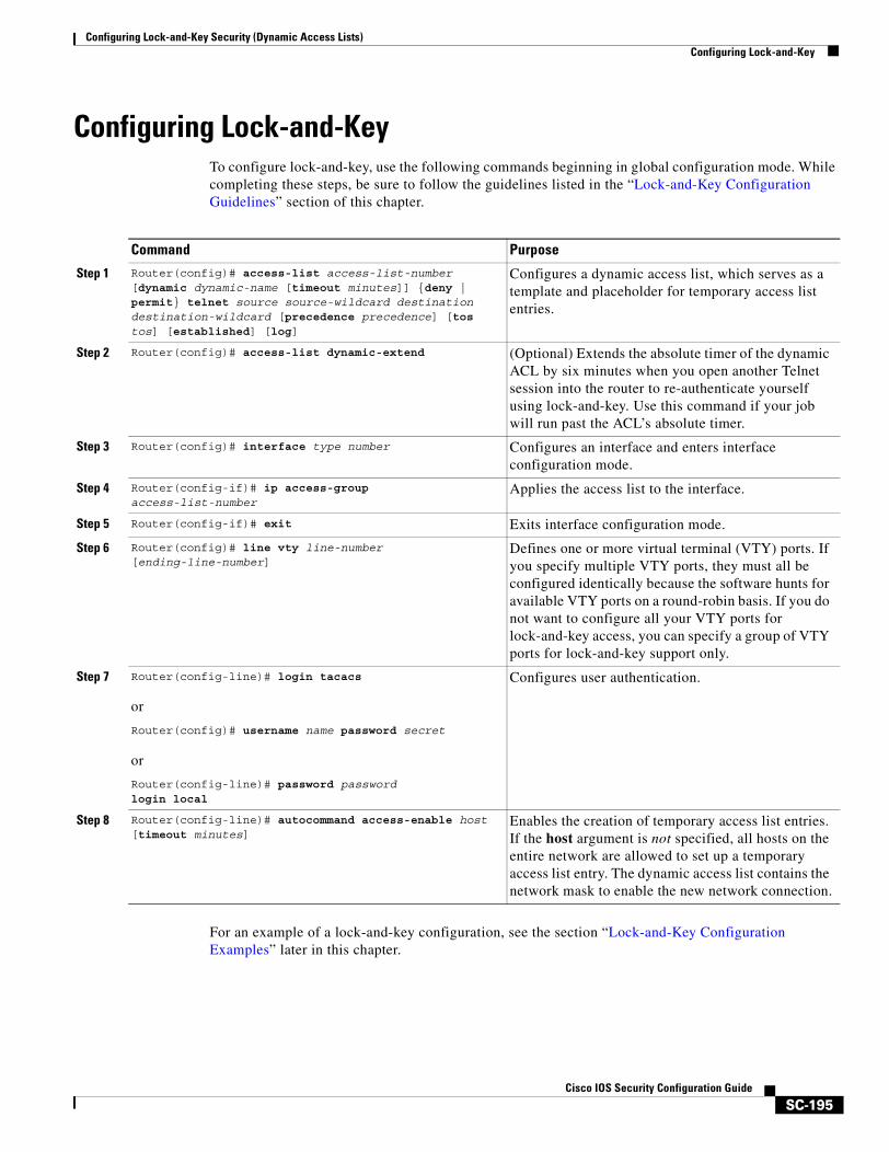
Configuring Lock-and-Key Security (Dynamic Access Lists)Configuring Lock-and-Key
SC-195Cisco IOS Security Configuration Guide
Configuring Lock-and-KeyTo configure lock-and-key, use the following commands beginning in global configuration mode. While completing these steps, be sure to follow the guidelines listed in the “Lock-and-Key Configuration Guidelines” section of this chapter.
For an example of a lock-and-key configuration, see the section “Lock-and-Key Configuration Examples” later in this chapter.
Command Purpose
Step 1 Router(config)# access-list access-list-number [dynamic dynamic-name [timeout minutes]] {deny | permit} telnet source source-wildcard destination destination-wildcard [precedence precedence] [tos tos] [established] [log]
Configures a dynamic access list, which serves as a template and placeholder for temporary access list entries.
Step 2 Router(config)# access-list dynamic-extend (Optional) Extends the absolute timer of the dynamic ACL by six minutes when you open another Telnet session into the router to re-authenticate yourself using lock-and-key. Use this command if your job will run past the ACL’s absolute timer.
Step 3 Router(config)# interface type number Configures an interface and enters interface configuration mode.
Step 4 Router(config-if)# ip access-group access-list-number
Applies the access list to the interface.
Step 5 Router(config-if)# exit Exits interface configuration mode.
Step 6 Router(config)# line vty line-number [ending-line-number]
Defines one or more virtual terminal (VTY) ports. If you specify multiple VTY ports, they must all be configured identically because the software hunts for available VTY ports on a round-robin basis. If you do not want to configure all your VTY ports for lock-and-key access, you can specify a group of VTY ports for lock-and-key support only.
Step 7 Router(config-line)# login tacacs
or
Router(config)# username name password secret
or
Router(config-line)# password password login local
Configures user authentication.
Step 8 Router(config-line)# autocommand access-enable host [timeout minutes]
Enables the creation of temporary access list entries. If the host argument is not specified, all hosts on the entire network are allowed to set up a temporary access list entry. The dynamic access list contains the network mask to enable the new network connection.

Configuring Lock-and-Key Security (Dynamic Access Lists)Configuring Lock-and-Key
SC-196Cisco IOS Security Configuration Guide
Lock-and-Key Configuration GuidelinesBefore you configure lock-and-key, you should understand the guidelines discussed in the following sections:
• Dynamic Access Lists
• Lock-and-Key Authentication
• The autocommand Command
Dynamic Access Lists
Use the following guidelines for configuring dynamic access lists:
• Do not create more than one dynamic access list for any one access list. The software only refers to the first dynamic access list defined.
• Do not assign the same dynamic-name to another access list. Doing so instructs the software to reuse the existing list. All named entries must be globally unique within the configuration.
• Assign attributes to the dynamic access list in the same way you assign attributes for a static access list. The temporary access list entries inherit the attributes assigned to this list.
• Configure Telnet as the protocol so that users must open a Telnet session into the router to be authenticated before they can gain access through the router.
• Either define an idle timeout now with the timeout keyword in the access-enable command in the autocommand command, or define an absolute timeout value later with the access-list command. You must define either an idle timeout or an absolute timeout—otherwise, the temporary access list entry will remain configured indefinitely on the interface (even after the user has terminated their session) until the entry is removed manually by an administrator. (You could configure both idle and absolute timeouts if you wish.)
• If you configure an idle timeout, the idle timeout value should be equal to the WAN idle timeout value.
• If you configure both idle and absolute timeouts, the idle timeout value must be less than the absolute timeout value.
• If you realize that a job will run past the the ACL’s absolute timer, use the access-list dynamic-extend command to extend the absolute timer of the dynamic ACL by six minutes. This command allows you to open a new Telnet session into the router to re-authentication yourself using lock-and-key.
• The only values replaced in the temporary entry are the source or destination address, depending whether the access list was in the input access list or output access list. All other attributes, such as port, are inherited from the main dynamic access list.
• Each addition to the dynamic list is always put at the beginning of the dynamic list. You cannot specify the order of temporary access list entries.
• Temporary access list entries are never written to NVRAM.
• To manually clear or to display dynamic access lists, refer to the section “Maintaining Lock-and-Key” later in this chapter.
Configuring Lock-and-Key Security (Dynamic Access Lists)Configuring Lock-and-Key
SC-197Cisco IOS Security Configuration Guide
Lock-and-Key Authentication
There are three possible methods to configure an authentication query process. These three methods are described in this section.
Note Cisco recommends that you use the TACACS+ server for your authentication query process. TACACS+ provides authentication, authorization, and accounting services. It also provides protocol support, protocol specification, and a centralized security database. Using a TACACS+ server is described in the next section, “Method 1—Configuring a Security Server.”
Method 1—Configuring a Security Server
Use a network access security server such as TACACS+ server. This method requires additional configuration steps on the TACACS+ server but allows for stricter authentication queries and more sophisticated tracking capabilities.
Router# login tacacs
Method 2—Configuring the username Command
Use the username command. This method is more effective because authentication is determined on a user basis.
Router# username name password password
Method 3—Configuring the password and login Commands
Use the password and login commands. This method is less effective because the password is configured for the port, not for the user. Therefore, any user who knows the password can authenticate successfully.
Router# password passwordRouter# login local
The autocommand Command
Use the following guidelines for configuring the autocommand command:
• If you use a TACACS+ server to authenticate the user, you should configure the autocommand command on the TACACS+ server as a per-user autocommand. If you use local authentication, use the autocommand command on the line.
• Configure all virtual terminal (VTY) ports with the same autocommand command. Omitting an autocommand command on a VTY port allows a random host to gain EXEC mode access to the router and does not create a temporary access list entry in the dynamic access list.
• If you did not previously define an idle timeout with the autocommand access-enable command, you must define an absolute timeout now with the access-list command. You must define either an idle timeout or an absolute timeout—otherwise, the temporary access list entry will remain configured indefinitely on the interface (even after the user has terminated their session) until the entry is removed manually by an administrator. (You could configure both idle and absolute timeouts if you wish.)
• If you configure both idle and absolute timeouts, the absolute timeout value must be greater than the idle timeout value.
Configuring Lock-and-Key Security (Dynamic Access Lists)Verifying Lock-and-Key Configuration
SC-198Cisco IOS Security Configuration Guide
Verifying Lock-and-Key ConfigurationYou can verify that lock-and-key is successfully configured on the router by asking a user to test the connection. The user should be at a host that is permitted in the dynamic access list, and the user should have AAA authentication and authorization configured.
To test the connection, the user should Telnet to the router, allow the Telnet session to close, and then attempt to access a host on the other side of the router. This host must be one that is permitted by the dynamic access list. The user should access the host with an application that uses the IP protocol.
The following sample display illustrates what end-users might see if they are successfully authenticated. Notice that the Telnet connection is closed immediately after the password is entered and authenticated. The temporary access list entry is then created, and the host that initiated the Telnet session now has access inside the firewall.
Router% telnet corporateTrying 172.21.52.1 ...Connected to corporate.example.com.Escape character is ‘^]’.User Access VerificationPassword:Connection closed by foreign host.
You can then use the show access-lists command at the router to view the dynamic access lists, which should include an additional entry permitting the user access through the router.
Maintaining Lock-and-Key When lock-and-key is in use, dynamic access lists will dynamically grow and shrink as entries are added and deleted. You need to make sure that entries are being deleted in a timely way, because while entries exist, the risk of a spoofing attack is present. Also, the more entries there are, the bigger the router performance impact will be.
If you do not have an idle or absolute timeout configured, entries will remain in the dynamic access list until you manually remove them. If this is the case, make sure that you are extremely vigilant about removing entries.
Displaying Dynamic Access List EntriesYou can display temporary access list entries when they are in use. After a temporary access list entry is cleared by you or by the absolute or idle timeout parameter, it can no longer be displayed. The number of matches displayed indicates the number of times the access list entry was hit.
To view dynamic access lists and any temporary access list entries that are currently established, use the following command in privileged EXEC mode:
Command PurposeRouter# show access-lists [access-list-number] Displays dynamic access lists and temporary access list entries.
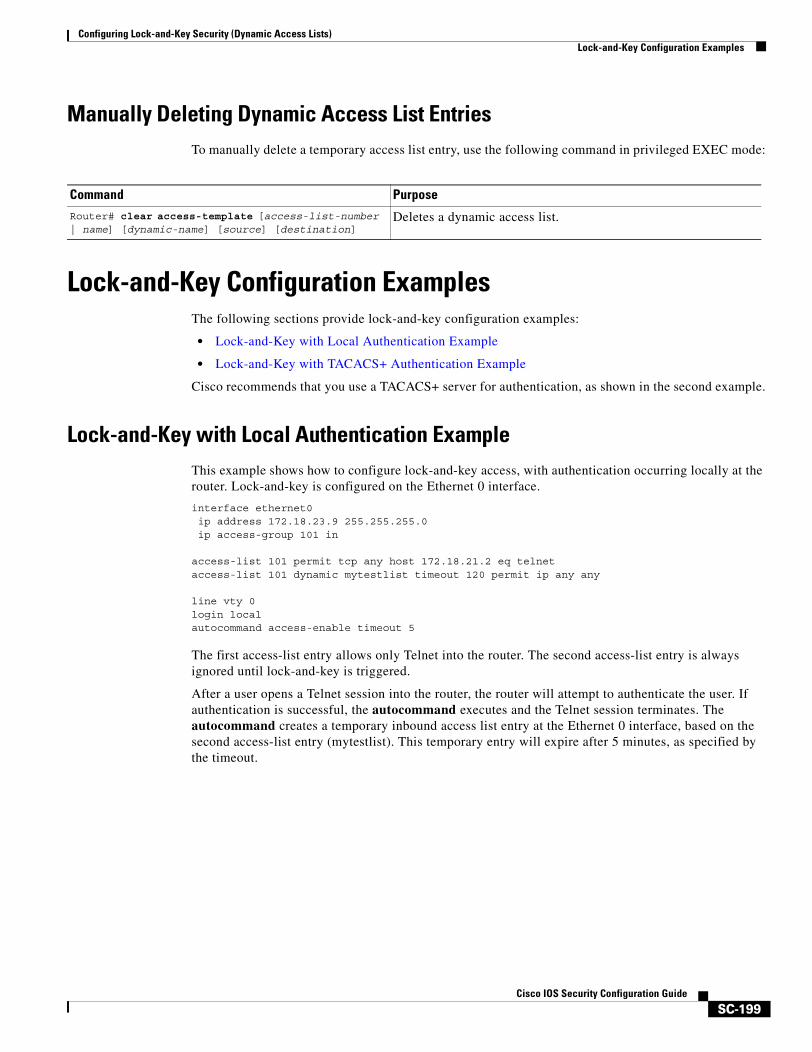
Configuring Lock-and-Key Security (Dynamic Access Lists)Lock-and-Key Configuration Examples
SC-199Cisco IOS Security Configuration Guide
Manually Deleting Dynamic Access List EntriesTo manually delete a temporary access list entry, use the following command in privileged EXEC mode:
Lock-and-Key Configuration ExamplesThe following sections provide lock-and-key configuration examples:
• Lock-and-Key with Local Authentication Example
• Lock-and-Key with TACACS+ Authentication Example
Cisco recommends that you use a TACACS+ server for authentication, as shown in the second example.
Lock-and-Key with Local Authentication ExampleThis example shows how to configure lock-and-key access, with authentication occurring locally at the router. Lock-and-key is configured on the Ethernet 0 interface.
interface ethernet0ip address 172.18.23.9 255.255.255.0ip access-group 101 in
access-list 101 permit tcp any host 172.18.21.2 eq telnetaccess-list 101 dynamic mytestlist timeout 120 permit ip any any
line vty 0login localautocommand access-enable timeout 5
The first access-list entry allows only Telnet into the router. The second access-list entry is always ignored until lock-and-key is triggered.
After a user opens a Telnet session into the router, the router will attempt to authenticate the user. If authentication is successful, the autocommand executes and the Telnet session terminates. The autocommand creates a temporary inbound access list entry at the Ethernet 0 interface, based on the second access-list entry (mytestlist). This temporary entry will expire after 5 minutes, as specified by the timeout.
Command Purpose
Router# clear access-template [access-list-number | name] [dynamic-name] [source] [destination]
Deletes a dynamic access list.
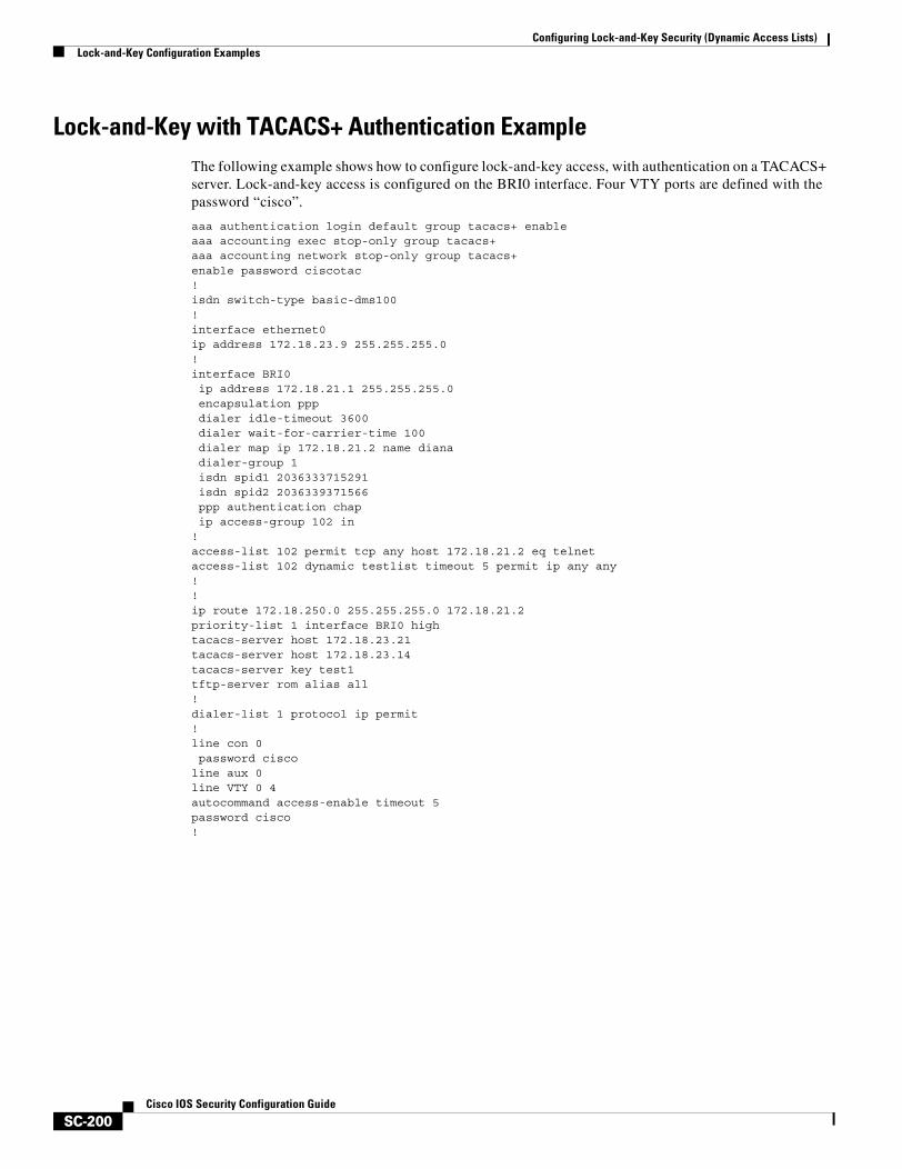
Configuring Lock-and-Key Security (Dynamic Access Lists)Lock-and-Key Configuration Examples
SC-200Cisco IOS Security Configuration Guide
Lock-and-Key with TACACS+ Authentication ExampleThe following example shows how to configure lock-and-key access, with authentication on a TACACS+ server. Lock-and-key access is configured on the BRI0 interface. Four VTY ports are defined with the password “cisco”.
aaa authentication login default group tacacs+ enableaaa accounting exec stop-only group tacacs+aaa accounting network stop-only group tacacs+enable password ciscotac!isdn switch-type basic-dms100!interface ethernet0ip address 172.18.23.9 255.255.255.0!interface BRI0ip address 172.18.21.1 255.255.255.0encapsulation pppdialer idle-timeout 3600dialer wait-for-carrier-time 100dialer map ip 172.18.21.2 name dianadialer-group 1isdn spid1 2036333715291isdn spid2 2036339371566ppp authentication chapip access-group 102 in
!access-list 102 permit tcp any host 172.18.21.2 eq telnetaccess-list 102 dynamic testlist timeout 5 permit ip any any!!ip route 172.18.250.0 255.255.255.0 172.18.21.2priority-list 1 interface BRI0 hightacacs-server host 172.18.23.21tacacs-server host 172.18.23.14tacacs-server key test1tftp-server rom alias all!dialer-list 1 protocol ip permit!line con 0password cisco
line aux 0line VTY 0 4autocommand access-enable timeout 5password cisco!
SC-201Cisco IOS Security Configuration Guide
Configuring IP Session Filtering (Reflexive Access Lists)
This chapter describes how to configure reflexive access lists on your router. Reflexive access lists provide the ability to filter network traffic at a router, based on IP upper-layer protocol “session” information.
For a complete description of reflexive access list commands, refer to the “Reflexive Access List Commands” chapter of the Cisco IOS Security Command Reference. To locate documentation of other commands that appear in this chapter, use the command reference master index or search online.
To identify the hardware platform or software image information associated with a feature, use the Feature Navigator on Cisco.com to search for information about the feature or refer to the software release notes for a specific release. For more information, see the chapter “Identifying Supported Platforms” section in the “Using Cisco IOS Software.”
In This ChapterThis chapter has the following sections:
• About Reflexive Access Lists
• Prework: Before You Configure Reflexive Access Lists
• Reflexive Access Lists Configuration Task List
• Reflexive Access List Configuration Examples
About Reflexive Access ListsReflexive access lists allow IP packets to be filtered based on upper-layer session information. You can use reflexive access lists to permit IP traffic for sessions originating from within your network but to deny IP traffic for sessions originating from outside your network. This is accomplished by reflexive filtering, a kind of session filtering.
Reflexive access lists can be defined with extended named IP access lists only. You cannot define reflexive access lists with numbered or standard named IP access lists or with other protocol access lists.
You can use reflexive access lists in conjunction with other standard access lists and static extended access lists.
Configuring IP Session Filtering (Reflexive Access Lists)About Reflexive Access Lists
SC-202Cisco IOS Security Configuration Guide
This section has the following sections:
• Benefits of Reflexive Access Lists
• What Is a Reflexive Access List?
• How Reflexive Access Lists Implement Session Filtering
• Where to Configure Reflexive Access Lists
• How Reflexive Access Lists Work
• Restrictions on Using Reflexive Access Lists
Benefits of Reflexive Access ListsReflexive access lists are an important part of securing your network against network hackers, and can be included in a firewall defense. Reflexive access lists provide a level of security against spoofing and certain denial-of-service attacks. Reflexive access lists are simple to use, and, compared to basic access lists, provide greater control over which packets enter your network.
What Is a Reflexive Access List?Reflexive access lists are similar in many ways to other access lists. Reflexive access lists contain condition statements (entries) that define criteria for permitting IP packets. These entries are evaluated in order, and when a match occurs, no more entries are evaluated.
However, reflexive access lists have significant differences from other types of access lists. Reflexive access lists contain only temporary entries; these entries are automatically created when a new IP session begins (for example, with an outbound packet), and the entries are removed when the session ends. Reflexive access lists are not themselves applied directly to an interface, but are “nested” within an extended named IP access list that is applied to the interface. (For more information about this, see the section “Reflexive Access Lists Configuration Task List” later in this chapter.) Also, reflexive access lists do not have the usual implicit “deny all traffic” statement at the end of the list, because of the nesting.
How Reflexive Access Lists Implement Session FilteringThis section compares session filtering with basic access lists to session filtering with reflexive access lists. This section contains the following sections:
• With Basic Access Lists
• With Reflexive Access Lists
With Basic Access Lists
With basic standard and static extended access lists, you can approximate session filtering by using the established keyword with the permit command. The established keyword filters TCP packets based on whether the ACK or RST bits are set. (Set ACK or RST bits indicate that the packet is not the first in the session, and therefore, that the packet belongs to an established session.) This filter criterion would be part of an access list applied permanently to an interface.
Configuring IP Session Filtering (Reflexive Access Lists)About Reflexive Access Lists
SC-203Cisco IOS Security Configuration Guide
With Reflexive Access Lists
Reflexive access lists, however, provide a truer form of session filtering, which is much harder to spoof because more filter criteria must be matched before a packet is permitted through. (For example, source and destination addresses and port numbers are checked, not just ACK and RST bits.) Also, session filtering uses temporary filters which are removed when a session is over. This limits the hacker’s attack opportunity to a smaller time window.
Moreover, the previous method of using the established keyword was available only for the TCP upper-layer protocol. So, for the other upper-layer protocols (such as UDP, ICMP, and so forth), you would have to either permit all incoming traffic or define all possible permissible source/destination host/port address pairs for each protocol. (Besides being an unmanageable task, this could exhaust NVRAM space.)
Where to Configure Reflexive Access ListsConfigure reflexive access lists on border routers—routers that pass traffic between an internal and external network. Often, these are firewall routers.
Note In this chapter, the words “within your network” and “internal network” refer to a network that is controlled (secured), such as your organization’s intranet, or to a part of your organization’s internal network that has higher security requirements than another part. “Outside your network” and “external network” refer to a network that is uncontrolled (unsecured) such as the Internet or to a part of your organization’s network that is not as highly secured.
How Reflexive Access Lists WorkA reflexive access list is triggered when a new IP upper-layer session (such as TCP or UDP) is initiated from inside your network, with a packet traveling to the external network. When triggered, the reflexive access list generates a new, temporary entry. This entry will permit traffic to enter your network if the traffic is part of the session, but will not permit traffic to enter your network if the traffic is not part of the session.
For example, if an outbound TCP packet is forwarded to outside of your network, and this packet is the first packet of a TCP session, then a new, temporary reflexive access list entry will be created. This entry is added to the reflexive access list, which applies to inbound traffic. The temporary entry has characteristics as described next.
This section contains the following sections:
• Temporary Access List Entry Characteristics
• When the Session Ends
Temporary Access List Entry Characteristics
• The entry is always a permit entry.
• The entry specifies the same protocol (TCP) as the original outbound TCP packet.
• The entry specifies the same source and destination addresses as the original outbound TCP packet, except the addresses are swapped.
Configuring IP Session Filtering (Reflexive Access Lists)Prework: Before You Configure Reflexive Access Lists
SC-204Cisco IOS Security Configuration Guide
• The entry specifies the same source and destination port numbers as the original outbound TCP packet, except the port numbers are swapped.
(This entry characteristic applies only for TCP and UDP packets. Other protocols, such as ICMP and IGMP, do not have port numbers, and other criteria are specified. For example, for ICMP, type numbers are used instead.)
• Inbound TCP traffic will be evaluated against the entry, until the entry expires. If an inbound TCP packet matches the entry, the inbound packet will be forwarded into your network.
• The entry will expire (be removed) after the last packet of the session passes through the interface.
• If no packets belonging to the session are detected for a configurable length of time (the timeout period), the entry will expire.
When the Session Ends
Temporary reflexive access list entries are removed at the end of the session. For TCP sessions, the entry is removed 5 seconds after two set FIN bits are detected, or immediately after matching a TCP packet with the RST bit set. (Two set FIN bits in a session indicate that the session is about to end; the 5-second window allows the session to close gracefully. A set RST bit indicates an abrupt session close.) Or, the temporary entry is removed after no packets of the session have been detected for a configurable length of time (the timeout period).
For UDP and other protocols, the end of the session is determined differently than for TCP. Because other protocols are considered to be connectionless (sessionless) services, there is no session tracking information embedded in packets. Therefore, the end of a session is considered to be when no packets of the session have been detected for a configurable length of time (the timeout period).
Restrictions on Using Reflexive Access ListsReflexive access lists do not work with some applications that use port numbers that change during a session. For example, if the port numbers for a return packet are different from the originating packet, the return packet will be denied, even if the packet is actually part of the same session.
The TCP application of FTP is an example of an application with changing port numbers. With reflexive access lists, if you start an FTP request from within your network, the request will not complete. Instead, you must use Passive FTP when originating requests from within your network.
Prework: Before You Configure Reflexive Access ListsBefore you configure reflexive access lists, you must decide whether to configure reflexive access lists on an internal or external interface, as described in the next section, “Choosing an Interface: Internal or External.”
You should also be sure that you have a basic understanding of the IP protocol and of access lists; specifically, you should know how to configure extended named IP access lists. To learn about configuring IP extended access lists, refer to the “Configuring IP Services” chapter of the Cisco IOS IP Configuration Guide.
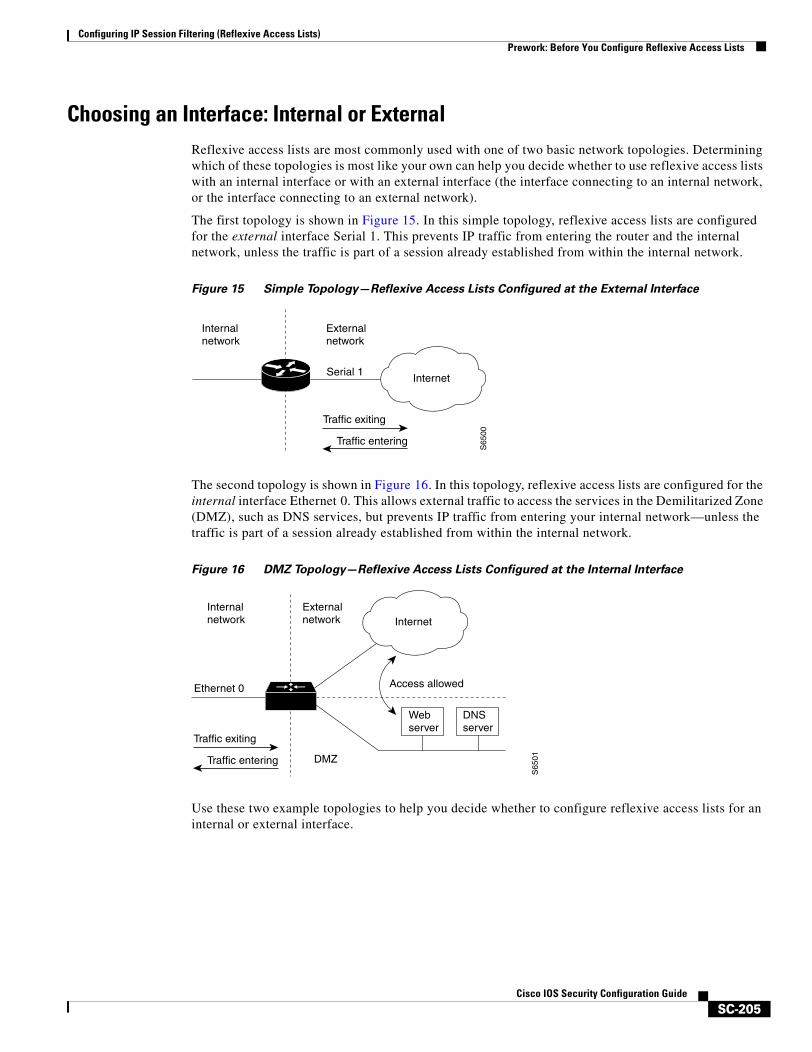
Configuring IP Session Filtering (Reflexive Access Lists)Prework: Before You Configure Reflexive Access Lists
SC-205Cisco IOS Security Configuration Guide
Choosing an Interface: Internal or ExternalReflexive access lists are most commonly used with one of two basic network topologies. Determining which of these topologies is most like your own can help you decide whether to use reflexive access lists with an internal interface or with an external interface (the interface connecting to an internal network, or the interface connecting to an external network).
The first topology is shown in Figure 15. In this simple topology, reflexive access lists are configured for the external interface Serial 1. This prevents IP traffic from entering the router and the internal network, unless the traffic is part of a session already established from within the internal network.
Figure 15 Simple Topology—Reflexive Access Lists Configured at the External Interface
The second topology is shown in Figure 16. In this topology, reflexive access lists are configured for the internal interface Ethernet 0. This allows external traffic to access the services in the Demilitarized Zone (DMZ), such as DNS services, but prevents IP traffic from entering your internal network—unless the traffic is part of a session already established from within the internal network.
Figure 16 DMZ Topology—Reflexive Access Lists Configured at the Internal Interface
Use these two example topologies to help you decide whether to configure reflexive access lists for an internal or external interface.
Internalnetwork
S65
00
Externalnetwork
InternetSerial 1
Traffic exiting
Traffic entering
Internalnetwork
Ethernet 0
S65
01
Externalnetwork
DMZ
Internet
Access allowed
Webserver
DNSserver
Traffic exiting
Traffic entering
Configuring IP Session Filtering (Reflexive Access Lists)Reflexive Access Lists Configuration Task List
SC-206Cisco IOS Security Configuration Guide
Reflexive Access Lists Configuration Task ListIn the previous section, “Prework: Before You Configure Reflexive Access Lists,” you decided whether to configure reflexive access lists for an internal or external interface.
Now, complete the tasks in one of the following configuration task lists:
• External Interface Configuration Task List
• Internal Interface Configuration Task List
For configuration examples, refer to the “Reflexive Access List Configuration Examples” section at the end of this chapter.
External Interface Configuration Task ListTo configure reflexive access lists for an external interface, perform the following tasks:
1. Defining the reflexive access list(s) in an outbound IP extended named access list
2. Nesting the reflexive access list(s) in an inbound IP extended named access list
3. Setting a global timeout value
These tasks are described in the sections following the “Internal Interface Configuration Task List” section.
Note The defined (outbound) reflexive access list evaluates traffic traveling out of your network: if the defined reflexive access list is matched, temporary entries are created in the nested (inbound) reflexive access list. These temporary entries will then be applied to traffic traveling into your network.
Internal Interface Configuration Task ListTo configure reflexive access lists for an internal interface, perform the following tasks:
1. Defining the reflexive access list(s) in an inbound IP extended named access list
2. Nesting the reflexive access list(s) in an outbound IP extended named access list
3. Setting a global timeout value
These tasks are described in the next sections.
Note The defined (inbound) reflexive access list is used to evaluate traffic traveling out of your network: if the defined reflexive access list is matched, temporary entries are created in the nested (outbound) reflexive access list. These temporary entries will then be applied to traffic traveling into your network.
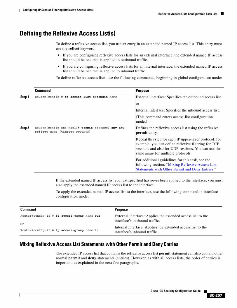
Configuring IP Session Filtering (Reflexive Access Lists)Reflexive Access Lists Configuration Task List
SC-207Cisco IOS Security Configuration Guide
Defining the Reflexive Access List(s)To define a reflexive access list, you use an entry in an extended named IP access list. This entry must use the reflect keyword.
• If you are configuring reflexive access lists for an external interface, the extended named IP access list should be one that is applied to outbound traffic.
• If you are configuring reflexive access lists for an internal interface, the extended named IP access list should be one that is applied to inbound traffic.
To define reflexive access lists, use the following commands, beginning in global configuration mode:
If the extended named IP access list you just specified has never been applied to the interface, you must also apply the extended named IP access list to the interface.
To apply the extended named IP access list to the interface, use the following command in interface configuration mode:
Mixing Reflexive Access List Statements with Other Permit and Deny Entries
The extended IP access list that contains the reflexive access list permit statement can also contain other normal permit and deny statements (entries). However, as with all access lists, the order of entries is important, as explained in the next few paragraphs.
Command Purpose
Step 1 Router(config)# ip access-list extended name External interface: Specifies the outbound access list.
or
Internal interface: Specifies the inbound access list.
(This command enters access-list configuration mode.)
Step 2 Router(config-ext-nacl)# permit protocol any any reflect name [timeout seconds]
Defines the reflexive access list using the reflexive permit entry.
Repeat this step for each IP upper-layer protocol; for example, you can define reflexive filtering for TCP sessions and also for UDP sessions. You can use the same name for multiple protocols.
For additional guidelines for this task, see the following section, “Mixing Reflexive Access List Statements with Other Permit and Deny Entries.”
Command PurposeRouter(config-if)# ip access-group name out
or
Router(config-if)# ip access-group name in
External interface: Applies the extended access list to the interface’s outbound traffic.
Internal interface: Applies the extended access list to the interface’s inbound traffic.
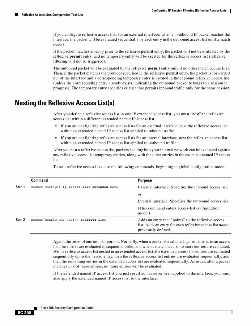
Configuring IP Session Filtering (Reflexive Access Lists)Reflexive Access Lists Configuration Task List
SC-208Cisco IOS Security Configuration Guide
If you configure reflexive access lists for an external interface, when an outbound IP packet reaches the interface, the packet will be evaluated sequentially by each entry in the outbound access list until a match occurs.
If the packet matches an entry prior to the reflexive permit entry, the packet will not be evaluated by the reflexive permit entry, and no temporary entry will be created for the reflexive access list (reflexive filtering will not be triggered).
The outbound packet will be evaluated by the reflexive permit entry only if no other match occurs first. Then, if the packet matches the protocol specified in the reflexive permit entry, the packet is forwarded out of the interface and a corresponding temporary entry is created in the inbound reflexive access list (unless the corresponding entry already exists, indicating the outbound packet belongs to a session in progress). The temporary entry specifies criteria that permits inbound traffic only for the same session.
Nesting the Reflexive Access List(s)After you define a reflexive access list in one IP extended access list, you must “nest” the reflexive access list within a different extended named IP access list.
• If you are configuring reflexive access lists for an external interface, nest the reflexive access list within an extended named IP access list applied to inbound traffic.
• If you are configuring reflexive access lists for an internal interface, nest the reflexive access list within an extended named IP access list applied to outbound traffic.
After you nest a reflexive access list, packets heading into your internal network can be evaluated against any reflexive access list temporary entries, along with the other entries in the extended named IP access list.
To nest reflexive access lists, use the following commands, beginning in global configuration mode:
Again, the order of entries is important. Normally, when a packet is evaluated against entries in an access list, the entries are evaluated in sequential order, and when a match occurs, no more entries are evaluated. With a reflexive access list nested in an extended access list, the extended access list entries are evaluated sequentially up to the nested entry, then the reflexive access list entries are evaluated sequentially, and then the remaining entries in the extended access list are evaluated sequentially. As usual, after a packet matches any of these entries, no more entries will be evaluated.
If the extended named IP access list you just specified has never been applied to the interface, you must also apply the extended named IP access list to the interface.
Command Purpose
Step 1 Router(config)# ip access-list extended name External interface: Specifies the inbound access list.
or
Internal interface: Specifies the outbound access list.
(This command enters access-list configuration mode.)
Step 2 Router(config-ext-nacl)# evaluate name Adds an entry that “points” to the reflexive access list. Adds an entry for each reflexive access list name previously defined.
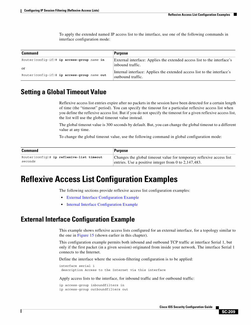
Configuring IP Session Filtering (Reflexive Access Lists)Reflexive Access List Configuration Examples
SC-209Cisco IOS Security Configuration Guide
To apply the extended named IP access list to the interface, use one of the following commands in interface configuration mode:
Setting a Global Timeout ValueReflexive access list entries expire after no packets in the session have been detected for a certain length of time (the “timeout” period). You can specify the timeout for a particular reflexive access list when you define the reflexive access list. But if you do not specify the timeout for a given reflexive access list, the list will use the global timeout value instead.
The global timeout value is 300 seconds by default. But, you can change the global timeout to a different value at any time.
To change the global timeout value, use the following command in global configuration mode:
Reflexive Access List Configuration ExamplesThe following sections provide reflexive access list configuration examples:
• External Interface Configuration Example
• Internal Interface Configuration Example
External Interface Configuration ExampleThis example shows reflexive access lists configured for an external interface, for a topology similar to the one in Figure 15 (shown earlier in this chapter).
This configuration example permits both inbound and outbound TCP traffic at interface Serial 1, but only if the first packet (in a given session) originated from inside your network. The interface Serial 1 connects to the Internet.
Define the interface where the session-filtering configuration is to be applied:
interface serial 1description Access to the Internet via this interface
Apply access lists to the interface, for inbound traffic and for outbound traffic:
ip access-group inboundfilters inip access-group outboundfilters out
Command PurposeRouter(config-if)# ip access-group name in
or
Router(config-if)# ip access-group name out
External interface: Applies the extended access list to the interface’s inbound traffic.
Internal interface: Applies the extended access list to the interface’s outbound traffic.
Command PurposeRouter(config)# ip reflexive-list timeout seconds
Changes the global timeout value for temporary reflexive access list entries. Use a positive integer from 0 to 2,147,483.
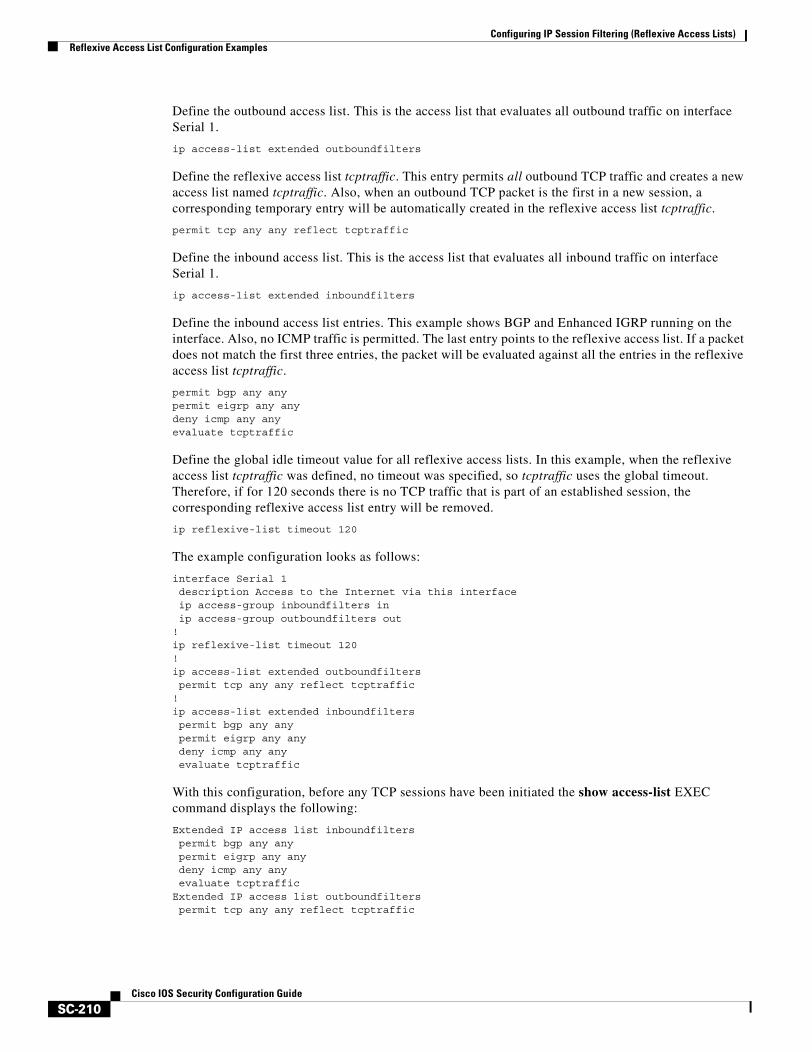
Configuring IP Session Filtering (Reflexive Access Lists)Reflexive Access List Configuration Examples
SC-210Cisco IOS Security Configuration Guide
Define the outbound access list. This is the access list that evaluates all outbound traffic on interface Serial 1.
ip access-list extended outboundfilters
Define the reflexive access list tcptraffic. This entry permits all outbound TCP traffic and creates a new access list named tcptraffic. Also, when an outbound TCP packet is the first in a new session, a corresponding temporary entry will be automatically created in the reflexive access list tcptraffic.
permit tcp any any reflect tcptraffic
Define the inbound access list. This is the access list that evaluates all inbound traffic on interface Serial 1.
ip access-list extended inboundfilters
Define the inbound access list entries. This example shows BGP and Enhanced IGRP running on the interface. Also, no ICMP traffic is permitted. The last entry points to the reflexive access list. If a packet does not match the first three entries, the packet will be evaluated against all the entries in the reflexive access list tcptraffic.
permit bgp any anypermit eigrp any anydeny icmp any anyevaluate tcptraffic
Define the global idle timeout value for all reflexive access lists. In this example, when the reflexive access list tcptraffic was defined, no timeout was specified, so tcptraffic uses the global timeout. Therefore, if for 120 seconds there is no TCP traffic that is part of an established session, the corresponding reflexive access list entry will be removed.
ip reflexive-list timeout 120
The example configuration looks as follows:
interface Serial 1description Access to the Internet via this interfaceip access-group inboundfilters inip access-group outboundfilters out
!ip reflexive-list timeout 120!ip access-list extended outboundfilterspermit tcp any any reflect tcptraffic
!ip access-list extended inboundfilterspermit bgp any anypermit eigrp any anydeny icmp any anyevaluate tcptraffic
With this configuration, before any TCP sessions have been initiated the show access-list EXEC command displays the following:
Extended IP access list inboundfilterspermit bgp any anypermit eigrp any anydeny icmp any anyevaluate tcptraffic
Extended IP access list outboundfilterspermit tcp any any reflect tcptraffic

Configuring IP Session Filtering (Reflexive Access Lists)Reflexive Access List Configuration Examples
SC-211Cisco IOS Security Configuration Guide
Notice that the reflexive access list does not appear in this output. This is because before any TCP sessions have been initiated, no traffic has triggered the reflexive access list, and the list is empty (has no entries). When empty, reflexive access lists do not show up in show access-list output.
After a Telnet connection is initiated from within your network to a destination outside of your network, the show access-list EXEC command displays the following:
Extended IP access list inboundfilterspermit bgp any any (2 matches)permit eigrp any anydeny icmp any anyevaluate tcptraffic
Extended IP access list outboundfilterspermit tcp any any reflect tcptraffic
Reflexive IP access list tcptrafficpermit tcp host 172.19.99.67 eq telnet host 192.168.60.185 eq 11005 (5 matches) (time
left 115 seconds)
Notice that the reflexive access list tcptraffic now appears and displays the temporary entry generated when the Telnet session initiated with an outbound packet.
Internal Interface Configuration ExampleThis is an example configuration for reflexive access lists configured for an internal interface. This example has a topology similar to the one in Figure 16 (shown earlier in this chapter).
This example is similar to the previous example; the only difference between this example and the previous example is that the entries for the outbound and inbound access lists are swapped. Please refer to the previous example for more details and descriptions.
interface Ethernet 0description Access from the I-net to our Internal Network via this interfaceip access-group inboundfilters inip access-group outboundfilters out
!ip reflexive-list timeout 120!ip access-list extended outboundfilterspermit bgp any anypermit eigrp any anydeny icmp any anyevaluate tcptraffic
!ip access-list extended inboundfilterspermit tcp any any reflect tcptraffic

Configuring IP Session Filtering (Reflexive Access Lists)Reflexive Access List Configuration Examples
SC-212Cisco IOS Security Configuration Guide
SC-213Cisco IOS Security Configuration Guide
Configuring TCP Intercept (Preventing Denial-of-Service Attacks)
This chapter describes how to configure your router to protect TCP servers from TCP SYN-flooding attacks, a type of denial-of-service attack. This is accomplished by configuring the Cisco IOS feature known as TCP Intercept.
For a complete description of TCP Intercept commands, refer to the “TCP Intercept Commands” chapter of the Cisco IOS Security Command Reference. To locate documentation of other commands that appear in this chapter, use the command reference master index or search online.
To identify the hardware platform or software image information associated with a feature, use the Feature Navigator on Cisco.com to search for information about the feature or refer to the software release notes for a specific release. For more information, see the chapter “Identifying Supported Platforms” section in the “Using Cisco IOS Software.”
In This ChapterThis chapter has the following sections:
• About TCP Intercept
• TCP Intercept Configuration Task List
• TCP Intercept Configuration Example
About TCP InterceptThe TCP intercept feature implements software to protect TCP servers from TCP SYN-flooding attacks, which are a type of denial-of-service attack.
A SYN-flooding attack occurs when a hacker floods a server with a barrage of requests for connection. Because these messages have unreachable return addresses, the connections cannot be established. The resulting volume of unresolved open connections eventually overwhelms the server and can cause it to deny service to valid requests, thereby preventing legitimate users from connecting to a web site, accessing e-mail, using FTP service, and so on.
The TCP intercept feature helps prevent SYN-flooding attacks by intercepting and validating TCP connection requests. In intercept mode, the TCP intercept software intercepts TCP synchronization (SYN) packets from clients to servers that match an extended access list. The software establishes a connection with the client on behalf of the destination server, and if successful, establishes the
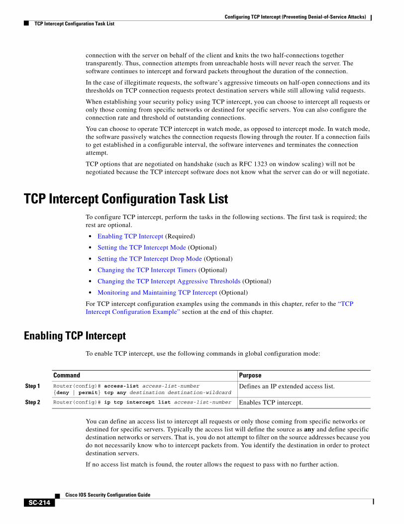
Configuring TCP Intercept (Preventing Denial-of-Service Attacks)TCP Intercept Configuration Task List
SC-214Cisco IOS Security Configuration Guide
connection with the server on behalf of the client and knits the two half-connections together transparently. Thus, connection attempts from unreachable hosts will never reach the server. The software continues to intercept and forward packets throughout the duration of the connection.
In the case of illegitimate requests, the software’s aggressive timeouts on half-open connections and its thresholds on TCP connection requests protect destination servers while still allowing valid requests.
When establishing your security policy using TCP intercept, you can choose to intercept all requests or only those coming from specific networks or destined for specific servers. You can also configure the connection rate and threshold of outstanding connections.
You can choose to operate TCP intercept in watch mode, as opposed to intercept mode. In watch mode, the software passively watches the connection requests flowing through the router. If a connection fails to get established in a configurable interval, the software intervenes and terminates the connection attempt.
TCP options that are negotiated on handshake (such as RFC 1323 on window scaling) will not be negotiated because the TCP intercept software does not know what the server can do or will negotiate.
TCP Intercept Configuration Task ListTo configure TCP intercept, perform the tasks in the following sections. The first task is required; the rest are optional.
• Enabling TCP Intercept (Required)
• Setting the TCP Intercept Mode (Optional)
• Setting the TCP Intercept Drop Mode (Optional)
• Changing the TCP Intercept Timers (Optional)
• Changing the TCP Intercept Aggressive Thresholds (Optional)
• Monitoring and Maintaining TCP Intercept (Optional)
For TCP intercept configuration examples using the commands in this chapter, refer to the “TCP Intercept Configuration Example” section at the end of this chapter.
Enabling TCP InterceptTo enable TCP intercept, use the following commands in global configuration mode:
You can define an access list to intercept all requests or only those coming from specific networks or destined for specific servers. Typically the access list will define the source as any and define specific destination networks or servers. That is, you do not attempt to filter on the source addresses because you do not necessarily know who to intercept packets from. You identify the destination in order to protect destination servers.
If no access list match is found, the router allows the request to pass with no further action.
Command Purpose
Step 1 Router(config)# access-list access-list-number {deny | permit} tcp any destination destination-wildcard
Defines an IP extended access list.
Step 2 Router(config)# ip tcp intercept list access-list-number Enables TCP intercept.
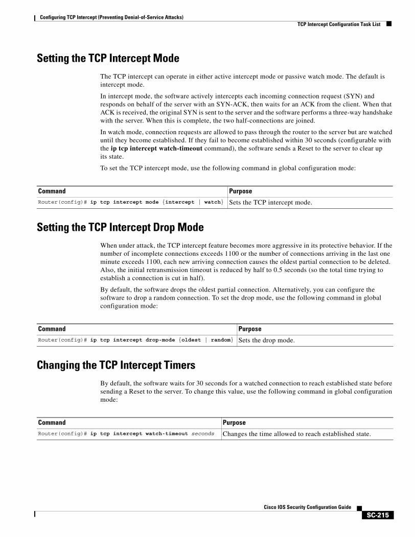
Configuring TCP Intercept (Preventing Denial-of-Service Attacks)TCP Intercept Configuration Task List
SC-215Cisco IOS Security Configuration Guide
Setting the TCP Intercept ModeThe TCP intercept can operate in either active intercept mode or passive watch mode. The default is intercept mode.
In intercept mode, the software actively intercepts each incoming connection request (SYN) and responds on behalf of the server with an SYN-ACK, then waits for an ACK from the client. When that ACK is received, the original SYN is sent to the server and the software performs a three-way handshake with the server. When this is complete, the two half-connections are joined.
In watch mode, connection requests are allowed to pass through the router to the server but are watched until they become established. If they fail to become established within 30 seconds (configurable with the ip tcp intercept watch-timeout command), the software sends a Reset to the server to clear up its state.
To set the TCP intercept mode, use the following command in global configuration mode:
Setting the TCP Intercept Drop ModeWhen under attack, the TCP intercept feature becomes more aggressive in its protective behavior. If the number of incomplete connections exceeds 1100 or the number of connections arriving in the last one minute exceeds 1100, each new arriving connection causes the oldest partial connection to be deleted. Also, the initial retransmission timeout is reduced by half to 0.5 seconds (so the total time trying to establish a connection is cut in half).
By default, the software drops the oldest partial connection. Alternatively, you can configure the software to drop a random connection. To set the drop mode, use the following command in global configuration mode:
Changing the TCP Intercept TimersBy default, the software waits for 30 seconds for a watched connection to reach established state before sending a Reset to the server. To change this value, use the following command in global configuration mode:
Command PurposeRouter(config)# ip tcp intercept mode {intercept | watch} Sets the TCP intercept mode.
Command Purpose
Router(config)# ip tcp intercept drop-mode {oldest | random} Sets the drop mode.
Command Purpose
Router(config)# ip tcp intercept watch-timeout seconds Changes the time allowed to reach established state.

Configuring TCP Intercept (Preventing Denial-of-Service Attacks)TCP Intercept Configuration Task List
SC-216Cisco IOS Security Configuration Guide
By default, the software waits for 5 seconds from receipt of a reset or FIN-exchange before it ceases to manage the connection. To change this value, use the following command in global configuration mode:
By default, the software still manages a connection for 24 hours after no activity. To change this value, use the following command in global configuration mode:
Changing the TCP Intercept Aggressive ThresholdsTwo factors determine when aggressive behavior begins and ends: total incomplete connections and connection requests during the last one-minute sample period. Both thresholds have default values that can be redefined.
When a threshold is exceeded, the TCP intercept assumes the server is under attack and goes into aggressive mode. When in aggressive mode, the following occurs:
• Each new arriving connection causes the oldest partial connection to be deleted. (You can change to a random drop mode.)
• The initial retransmission timeout is reduced by half to 0.5 seconds, and so the total time trying to establish the connection is cut in half. (When not in aggressive mode, the code does exponential back-off on its retransmissions of SYN segments. The initial retransmission timeout is 1 second. The subsequent timeouts are 2 seconds, 4 seconds, 8 seconds, and 16 seconds. The code retransmits 4 times before giving up, so it gives up after 31 seconds of no acknowledgment.)
• If in watch mode, the watch timeout is reduced by half. (If the default is in place, the watch timeout becomes 15 seconds.)
The drop strategy can be changed from the oldest connection to a random connection with the ip tcp intercept drop-mode command.
Note The two factors that determine aggressive behavior are related and work together. When either of the high values is exceeded, aggressive behavior begins. When both quantities fall below the low value, aggressive behavior ends.
Command PurposeRouter(config)# ip tcp intercept finrst-timeout seconds Changes the time between receipt of a reset or
FIN-exchange and dropping the connection.
Command PurposeRouter(config)# ip tcp intercept connection-timeout seconds Changes the time the software will manage a
connection after no activity.
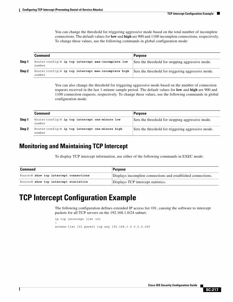
Configuring TCP Intercept (Preventing Denial-of-Service Attacks)TCP Intercept Configuration Example
SC-217Cisco IOS Security Configuration Guide
You can change the threshold for triggering aggressive mode based on the total number of incomplete connections. The default values for low and high are 900 and 1100 incomplete connections, respectively. To change these values, use the following commands in global configuration mode:
You can also change the threshold for triggering aggressive mode based on the number of connection requests received in the last 1-minute sample period. The default values for low and high are 900 and 1100 connection requests, respectively. To change these values, use the following commands in global configuration mode:
Monitoring and Maintaining TCP InterceptTo display TCP intercept information, use either of the following commands in EXEC mode:
TCP Intercept Configuration ExampleThe following configuration defines extended IP access list 101, causing the software to intercept packets for all TCP servers on the 192.168.1.0/24 subnet:
ip tcp intercept list 101!access-list 101 permit tcp any 192.168.1.0 0.0.0.255
Command Purpose
Step 1 Router(config)# ip tcp intercept max-incomplete low number
Sets the threshold for stopping aggressive mode.
Step 2 Router(config)# ip tcp intercept max-incomplete high number
Sets the threshold for triggering aggressive mode.
Command Purpose
Step 1 Router(config)# ip tcp intercept one-minute low number
Sets the threshold for stopping aggressive mode.
Step 2 Router(config)# ip tcp intercept one-minute high number
Sets the threshold for triggering aggressive mode.
Command PurposeRouter# show tcp intercept connections Displays incomplete connections and established connections.
Router# show tcp intercept statistics Displays TCP intercept statistics.

Configuring TCP Intercept (Preventing Denial-of-Service Attacks)TCP Intercept Configuration Example
SC-218Cisco IOS Security Configuration Guide
SC-219Cisco IOS Security Configuration Guide
Configuring Context-Based Access Control
This chapter describes how to configure Context-based Access Control (CBAC). CBAC provides advanced traffic filtering functionality and can be used as an integral part of your network’s firewall. For more information regarding firewalls, refer to the chapter “Cisco IOS Firewall Overview.”
For a complete description of the CBAC commands used in this chapter, refer to the “Context-Based Access Control Commands” chapter in the Cisco IOS Security Command Reference. To locate documentation of other commands that appear in this chapter, use the command reference master index or search online.
To identify the hardware platform or software image information associated with a feature, use the Feature Navigator on Cisco.com to search for information about the feature or refer to the software release notes for a specific release. For more information, see the chapter “Identifying Supported Platforms” section in the “Using Cisco IOS Software.”
In This ChapterThis chapter has the following sections:
• About Context-Based Access Control
• CBAC Configuration Task List
• Monitoring and Maintaining CBAC
• CBAC Configuration Examples
About Context-Based Access Control This section describes CBAC features and functions:
• What CBAC Does
• What CBAC Does Not Do
• How CBAC Works
• When and Where to Configure CBAC
• The CBAC Process
• Supported Protocols
• Restrictions
• Memory and Performance Impact
Configuring Context-Based Access ControlAbout Context-Based Access Control
SC-220Cisco IOS Security Configuration Guide
What CBAC DoesCBAC works to provide network protection on multiple levels using the following functions:
• Traffic Filtering
• Traffic Inspection
• Alerts and Audit Trails
• Intrusion Detection
Traffic Filtering
CBAC intelligently filters TCP and UDP packets based on application-layer protocol session information. You can configure CBAC to permit specified TCP and UDP traffic through a firewall only when the connection is initiated from within the network you want to protect. CBAC can inspect traffic for sessions that originate from either side of the firewall, and CBAC can be used for intranet, extranet, and Internet perimeters of your network.
Without CBAC, traffic filtering is limited to access list implementations that examine packets at the network layer, or at most, the transport layer. However, CBAC examines not only network layer and transport layer information but also examines the application-layer protocol information (such as FTP connection information) to learn about the state of the session. This allows support of protocols that involve multiple channels created as a result of negotiations in the control channel. Most of the multimedia protocols as well as some other protocols (such as FTP, RPC, and SQL*Net) involve multiple channels.
Using CBAC, Java blocking can be configured to filter HTTP traffic based on the server address or to completely deny access to Java applets that are not embedded in an archived or compressed file. With Java, you must protect against the risk of users inadvertently downloading destructive applets into your network. To protect against this risk, you could require all users to disable Java in their browser. If this is not an acceptable solution, you can create a CBAC inspection rule to filter Java applets at the firewall, which allows users to download only applets residing within the firewall and trusted applets from outside the firewall. For extensive content filtering of Java, Active-X, or virus scanning, you might want to consider purchasing a dedicated content filtering product.
Traffic Inspection
CBAC inspects traffic that travels through the firewall to discover and manage state information for TCP and UDP sessions. This state information is used to create temporary openings in the firewall’s access lists to allow return traffic and additional data connections for permissible sessions.
Inspecting packets at the application layer, and maintaining TCP and UDP session information, provides CBAC with the ability to detect and prevent certain types of network attacks such as SYN-flooding. A SYN-flood attack occurs when a network attacker floods a server with a barrage of requests for connection and does not complete the connection. The resulting volume of half-open connections can overwhelm the server, causing it to deny service to valid requests. Network attacks that deny access to a network device are called denial-of-service (DoS) attacks.
CBAC helps to protect against DoS attacks in other ways. CBAC inspects packet sequence numbers in TCP connections to see if they are within expected ranges—CBAC drops any suspicious packets. You can also configure CBAC to drop half-open connections, which require firewall processing and memory resources to maintain. Additionally, CBAC can detect unusually high rates of new connections and issue alert messages.
Configuring Context-Based Access ControlAbout Context-Based Access Control
SC-221Cisco IOS Security Configuration Guide
CBAC can help by protecting against certain DoS attacks involving fragmented IP packets. Even though the firewall prevents an attacker from making actual connections to a given host, the attacker can disrupt services provided by that host. This is done by sending many non-initial IP fragments or by sending complete fragmented packets through a router with an ACL that filters the first fragment of a fragmented packet. These fragments can tie up resources on the target host as it tries to reassemble the incomplete packets.
Alerts and Audit Trails
CBAC also generates real-time alerts and audit trails. Enhanced audit trail features use SYSLOG to track all network transactions; recording time stamps, source host, destination host, ports used, and the total number of transmitted bytes, for advanced, session-based reporting. Real-time alerts send SYSLOG error messages to central management consoles upon detecting suspicious activity. Using CBAC inspection rules, you can configure alerts and audit trail information on a per-application protocol basis. For example, if you want to generate audit trail information for HTTP traffic, you can specify that in the CBAC rule covering HTTP inspection.
Intrusion Detection
CBAC provides a limited amount of intrusion detection to protect against specific SMTP attacks. With intrusion detection, SYSLOG messages are reviewed and monitored for specific “attack signatures.” Certain types of network attacks have specific characteristics, or signatures. When CBAC detects an attacks, it resets the offending connections and sends SYSLOG information to the SYSLOG server. Refer to the section “Interpreting Syslog and Console Messages Generated by CBAC” later in this chapter for a list of supported signatures.
In addition to the limited intrusion detection offered by CBAC, the Cisco IOS Firewall feature set offers intrusion detection technology for mid-range and high-end router platforms using the Cisco IOS Firewall Intrusion Detection System (IDS). It is ideal for any network perimeter, and especially for locations in which a router is being deployed and additional security between network segments is required. It also can protect intranet and extranet connections where additional security is mandated, and branch-office sites connecting to the corporate office or Internet.
The Cisco IOS Firewall IDS identifies 59 of the most common attacks using signatures to detect patterns of misuse in network traffic. The intrusion-detection signatures available in the new release of the Cisco IOS Firewall feature set were chosen from a broad cross-section of intrusion-detection signatures. The signatures represent severe breaches of security and the most common network attacks and information-gathering scans.
For more information about Cisco IOS Firewall IDS, refer to the chapter “Configuring Cisco IOS Firewall Intrusion Detection System.”
Configuring Context-Based Access ControlAbout Context-Based Access Control
SC-222Cisco IOS Security Configuration Guide
What CBAC Does Not DoCBAC does not provide intelligent filtering for all protocols; it only works for the protocols that you specify. If you do not specify a certain protocol for CBAC, the existing access lists will determine how that protocol is filtered. No temporary openings will be created for protocols not specified for CBAC inspection.
CBAC does not protect against attacks originating from within the protected network unless that traffic travels through a router that has the Cisco IOS Firewall feature set deployed on it. CBAC only detects and protects against attacks that travel through the firewall. This is a scenario in which you might want to deploy CBAC on an intranet-based router.
CBAC protects against certain types of attacks, but not every type of attack. CBAC should not be considered a perfect, impenetrable defense. Determined, skilled attackers might be able to launch effective attacks. While there is no such thing as a perfect defense, CBAC detects and prevents most of the popular attacks on your network.
How CBAC WorksYou should understand the material in this section before you configure CBAC. If you do not understand how CBAC works, you might inadvertently introduce security risks by configuring CBAC inappropriately. This section contains the following sections:
• How CBAC Works—Overview
• How CBAC Works—Details
How CBAC Works—Overview
CBAC creates temporary openings in access lists at firewall interfaces. These openings are created when specified traffic exits your internal network through the firewall. The openings allow returning traffic (that would normally be blocked) and additional data channels to enter your internal network back through the firewall. The traffic is allowed back through the firewall only if it is part of the same session as the original traffic that triggered CBAC when exiting through the firewall.
Throughout this chapter, the terms “inbound” and “outbound” are used to describe the direction of traffic relative to the router interface on which CBAC is applied. For example, if a CBAC rule is applied inbound on interface E0, then packets entering interface E0 from the network will be inspected. If a CBAC rule is applied outbound on interface E0, then packets leaving interface E0 to the network will be inspected. This is similar to the way ACLs work.
For example, consider a CBAC inspection rule named hqusers, and suppose that rule is applied inbound at interface E0:
router (config-if)# ip inspect hqusers in
This command causes CBAC to inspect the packets coming into this interface from the network. If a packet is attempting to initiate a session, CBAC will then determine if this protocol is allowed, create a CBAC session, add the appropriate ACLs to allow return traffic and do any needed content inspection on any future packets for this session.
The terms “input” and “output” are used to describe the interfaces at which network traffic enters or exits the firewall router. A packet enters the firewall router via the input interface, is inspected by the firewall software and then exits the router via the output interface.
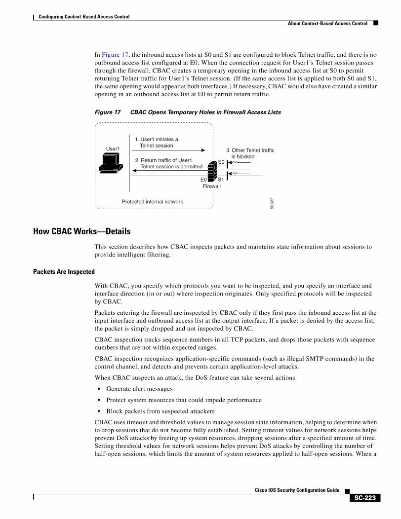
Configuring Context-Based Access ControlAbout Context-Based Access Control
SC-223Cisco IOS Security Configuration Guide
In Figure 17, the inbound access lists at S0 and S1 are configured to block Telnet traffic, and there is no outbound access list configured at E0. When the connection request for User1’s Telnet session passes through the firewall, CBAC creates a temporary opening in the inbound access list at S0 to permit returning Telnet traffic for User1’s Telnet session. (If the same access list is applied to both S0 and S1, the same opening would appear at both interfaces.) If necessary, CBAC would also have created a similar opening in an outbound access list at E0 to permit return traffic.
Figure 17 CBAC Opens Temporary Holes in Firewall Access Lists
How CBAC Works—Details
This section describes how CBAC inspects packets and maintains state information about sessions to provide intelligent filtering.
Packets Are Inspected
With CBAC, you specify which protocols you want to be inspected, and you specify an interface and interface direction (in or out) where inspection originates. Only specified protocols will be inspected by CBAC.
Packets entering the firewall are inspected by CBAC only if they first pass the inbound access list at the input interface and outbound access list at the output interface. If a packet is denied by the access list, the packet is simply dropped and not inspected by CBAC.
CBAC inspection tracks sequence numbers in all TCP packets, and drops those packets with sequence numbers that are not within expected ranges.
CBAC inspection recognizes application-specific commands (such as illegal SMTP commands) in the control channel, and detects and prevents certain application-level attacks.
When CBAC suspects an attack, the DoS feature can take several actions:
• Generate alert messages
• Protect system resources that could impede performance
• Block packets from suspected attackers
CBAC uses timeout and threshold values to manage session state information, helping to determine when to drop sessions that do not become fully established. Setting timeout values for network sessions helps prevent DoS attacks by freeing up system resources, dropping sessions after a specified amount of time. Setting threshold values for network sessions helps prevent DoS attacks by controlling the number of half-open sessions, which limits the amount of system resources applied to half-open sessions. When a
1. User1 initiates a Telnet session
3. Other Telnet trafficis blocked
E0
S0
S1
User1
S69
27Protected internal network
2. Return traffic of User1 Telnet session is permitted
Firewall
Configuring Context-Based Access ControlAbout Context-Based Access Control
SC-224Cisco IOS Security Configuration Guide
session is dropped, CBAC sends a reset message to the devices at both end points (source and destination) of the session. When the system under DoS attack receives a reset command, it releases, or frees up, processes and resources related to that incomplete session.
CBAC provides three thresholds against DoS attacks:
• The total number of half-open TCP or UDP sessions
• The number of half-open sessions based upon time
• The number of half-open TCP-only sessions per host
If a threshold is exceeded, CBAC has two options:
• Send a reset message to the end points of the oldest half-open session, making resources available to service newly arriving SYN packets.
• In the case of half open TCP only sessions, CBAC blocks all SYN packets temporarily for the duration configured by the threshold value. When the router blocks a SYN packet, the TCP three-way handshake is never initiated, which prevents the router from using memory and processing resources needed for valid connections.
DoS detection and prevention requires that you create a CBAC inspection rule and apply that rule on an interface. The inspection rule must include the protocols that you want to monitor against DoS attacks. For example, if you have TCP inspection enabled on the inspection rule, then CBAC can track all TCP connections to watch for DoS attacks. If the inspection rule includes FTP protocol inspection but not TCP inspection, CBAC tracks only FTP connections for DoS attacks.
For detailed information about setting timeout and threshold values in CBAC to detect and prevent DoS attacks, refer in the “Configuring Global Timeouts and Thresholds” section.
A State Table Maintains Session State Information
Whenever a packet is inspected, a state table is updated to include information about the state of the session.
Return traffic will only be permitted back through the firewall if the state table contains information indicating that the packet belongs to a permissible session. CBAC controls the traffic that belongs to a valid session. When return traffic is inspected, the state table information is updated as necessary.
UDP “Sessions” Are Approximated
With UDP—a connectionless service—there are no actual sessions, so the software approximates sessions by examining the information in the packet and determining if the packet is similar to other UDP packets (for example, same source/destination addresses and port numbers) and if the packet was detected soon after another similar UDP packet. “Soon” means within the configurable UDP idle timeout period.
Access List Entries Are Dynamically Created and Deleted to Permit Return Traffic and Additional Data Connections
CBAC dynamically creates and deletes access list entries at the firewall interfaces, according to the information maintained in the state tables. These access list entries are applied to the interfaces to examine traffic flowing back into the internal network. These entries create temporary openings in the firewall to permit only traffic that is part of a permissible session.
The temporary access list entries are never saved to NVRAM.
Configuring Context-Based Access ControlAbout Context-Based Access Control
SC-225Cisco IOS Security Configuration Guide
When and Where to Configure CBACConfigure CBAC at firewalls protecting internal networks. Such firewalls should be Cisco routers with the Cisco IOS Firewall feature set configured as described previously in the section “Cisco IOS Firewall.”
Use CBAC when the firewall will be passing traffic such as the following:
• Standard TCP and UDP Internet applications
• Multimedia applications
• Oracle support
Use CBAC for these applications if you want the application’s traffic to be permitted through the firewall only when the traffic session is initiated from a particular side of the firewall (usually from the protected internal network).
In many cases, you will configure CBAC in one direction only at a single interface, which causes traffic to be permitted back into the internal network only if the traffic is part of a permissible (valid, existing) session. This is a typical configuration for protecting your internal networks from traffic that originates on the Internet.
You can also configure CBAC in two directions at one or more interfaces. CBAC is configured in two directions when the networks on both sides of the firewall should be protected, such as with extranet or intranet configurations, and to protect against DoS attacks. For example, if the firewall is situated between two partner companies’ networks, you might wish to restrict traffic in one direction for certain applications, and restrict traffic in the opposite direction for other applications.
The CBAC ProcessThis section describes a sample sequence of events that occurs when CBAC is configured at an external interface that connects to an external network such as the Internet.
In this example, a TCP packet exits the internal network through the firewall’s external interface. The TCP packet is the first packet of a Telnet session, and TCP is configured for CBAC inspection.
1. The packet reaches the firewall’s external interface.
2. The packet is evaluated against the interface’s existing outbound access list, and the packet is permitted. (A denied packet would simply be dropped at this point.)
3. The packet is inspected by CBAC to determine and record information about the state of the packet’s connection. This information is recorded in a new state table entry created for the new connection.
(If the packet’s application—Telnet—was not configured for CBAC inspection, the packet would simply be forwarded out the interface at this point without being inspected by CBAC. See the section “Defining an Inspection Rule” later in this chapter for information about configuring CBAC inspection.)
4. Based on the obtained state information, CBAC creates a temporary access list entry which is inserted at the beginning of the external interface’s inbound extended access list. This temporary access list entry is designed to permit inbound packets that are part of the same connection as the outbound packet just inspected.
5. The outbound packet is forwarded out the interface.
6. Later, an inbound packet reaches the interface. This packet is part of the same Telnet connection previously established with the outbound packet. The inbound packet is evaluated against the inbound access list, and it is permitted because of the temporary access list entry previously created.
Configuring Context-Based Access ControlAbout Context-Based Access Control
SC-226Cisco IOS Security Configuration Guide
7. The permitted inbound packet is inspected by CBAC, and the connection’s state table entry is updated as necessary. Based on the updated state information, the inbound extended access list temporary entries might be modified in order to permit only packets that are valid for the current state of the connection.
8. Any additional inbound or outbound packets that belong to the connection are inspected to update the state table entry and to modify the temporary inbound access list entries as required, and they are forwarded through the interface.
9. When the connection terminates or times out, the connection’s state table entry is deleted, and the connection’s temporary inbound access list entries are deleted.
In the sample process just described, the firewall access lists are configured as follows:
• An outbound IP access list (standard or extended) is applied to the external interface. This access list permits all packets that you want to allow to exit the network, including packets you want to be inspected by CBAC. In this case, Telnet packets are permitted.
• An inbound extended IP access list is applied to the external interface. This access list denies any traffic to be inspected by CBAC—including Telnet packets. When CBAC is triggered with an outbound packet, CBAC creates a temporary opening in the inbound access list to permit only traffic that is part of a valid, existing session.
If the inbound access list had been configured to permit all traffic, CBAC would be creating pointless openings in the firewall for packets that would be permitted anyway.
Supported ProtocolsThis section provides a list of CBAC supported protocols and includes a more detailed look at support for multimedia applications, specifically RTSP and H.323.
CBAC Supported Protocols
You can configure CBAC to inspect the following types of sessions:
• All TCP sessions, regardless of the application-layer protocol (sometimes called “single-channel” or “generic” TCP inspection)
• All UDP sessions, regardless of the application-layer protocol (sometimes called “single-channel” or “generic” UDP inspection)
You can also configure CBAC to specifically inspect certain application-layer protocols. The following application-layer protocols can all be configured for CBAC:
• CU-SeeMe (only the White Pine version)
• FTP
• H.323 (such as NetMeeting, ProShare)
• HTTP (Java blocking)
• Microsoft NetShow
• UNIX R-commands (such as rlogin, rexec, and rsh)
• RealAudio
• RTSP (Real Time Streaming Protocol)
• RPC (Sun RPC, not DCE RPC)
Configuring Context-Based Access ControlAbout Context-Based Access Control
SC-227Cisco IOS Security Configuration Guide
• SMTP (Simple Mail Transport Protocol)
Note CBAC can be configured to inspect SMTP but not ESMTP (Extended Simple Mail Transport Protocol). SMTP is described in RFC 821. CBAC SMTP inspect does not inspect the ESMTP session or command sequence. Configuring SMTP inspection is not useful for ESMTP, and it can cause problems.
To determine whether a mail-server is doing SMTP or ESMTP, contact your mail-server software vendor, or telnet to the mail-server port 25 and observe the banner to see if it reports SMTP or ESMTP.
• SQL*Net
• StreamWorks
• TFTP
• VDOLive
When a protocol is configured for CBAC, that protocol traffic is inspected, state information is maintained, and in general, packets are allowed back through the firewall only if they belong to a permissible session.
RTSP and H.323 Protocol Support for Multimedia Applications
CBAC supports a number of protocols for multimedia applications that require delivery of data with real-time properties such as audio and video conferencing. This support includes the following multimedia application protocols:
• Real Time Streaming Protocol (RTSP)
• H.323 Version 2 (H.323 V2)
RTSP and H.323 V2 inspection allows clients on a protected network to receive data associated with a multimedia session from a server on an unprotected network.
RTSP Support
RTSP is the IETF standards-based protocol (RFC 2326) for control over the delivery of data with real-time properties such as audio and video streams. It is useful for large-scale broadcasts and audio or video on demand streaming, and is supported by a variety of vendor products of streaming audio and video multimedia, including Cisco IP/TV, RealNetworks RealAudio G2 Player, and Apple QuickTime 4 software.
RFC 2326 allows RTSP to run over either UDP or TCP, though CBAC currently supports only TCP-based RTSP. RTSP establishes a TCP-based control connection, or channel, between the multimedia client and server. RTSP uses this channel to control commands such as “play” and “pause” between the client and server. These control commands and responses are text-based and are similar to HTTP.
RTSP typically relies on a UDP-based data transport protocol such as standard Real-Time Transport Protocol (RTP) to open separate channels for data and for RTP Control Protocol (RTCP) messages. RTP and RTCP channels occur in pairs, with RTP being an even numbered port and RTCP being the next consecutive port. Understanding the relationship of RTP and RTCP is important for verifying session information using CBAC show commands.
Configuring Context-Based Access ControlAbout Context-Based Access Control
SC-228Cisco IOS Security Configuration Guide
The RTSP client uses TCP port 554 or 8554 to open a multimedia connection with a server. The data channel or data control channel (using RTCP) between the client and the server is dynamically negotiated between the client and the server using any of the high UDP ports (1024 to 65536).
CBAC uses this port information along with connection information from the client to create dynamic access control list (ACL) entries in the firewall. As TCP or UDP connections are terminated, CBAC removes these dynamic entries from the appropriate ACLs.
CBAC support for RTSP includes the following data transport modes:
• Standard Real-Time Transport Protocol (RTP)
RTP is an IETF standard (RFC 1889) supporting delivery of real-time data such as audio and video. RTP uses the RTP Control Protocol (RTCP) for managing the delivery of the multimedia data stream. This is the normal mode of operation for Cisco IP/TV and Apple QuickTime 4 software.
• RealNetworks Real Data Transport (RDT)
RDT is a proprietary protocol developed by RealNetworks for data transport. This mode uses RTSP for communication control and uses RDT for the data connection and retransmission of lost packets. This is the normal mode of operation for the RealServer G2 from RealNetworks.
• Interleaved (Tunnel Mode)
In this mode, RTSP uses the control channel to tunnel RTP or RDT traffic.
• Synchronized Multimedia Integration Language (SMIL)
SMIL is a layout language that enables the creation of multimedia presentations consisting of multiple elements of music, voice, images, text, video and graphics. This involves multiple RTSP control and data streams between the player and the servers. This mode is available only using RTSP and RDT. SMIL is a proposed specification of the World Wide Web Consortium (W3C). The RealNetworks RealServer and RealServer G2 provide support for SMIL—Cisco IP/TV and Apple QuickTime 4 do not.
H.323 Support
CBAC support for H.323 inspection includes H.323 Version 2 and H.323 Version 1. H.323 V2 provides additional options over H.323 V1, including a “fast start” option. The fast start option minimizes the delay between the time that a user initiates a connection and the time that the user gets the data (voice, video). H.323 V2 inspection is backward compatible with H.323 V1.
With H.323 V1, after a TCP connection is established between the client and server (H.225 Channel), a separate channel for media control (H.245 Channel) is opened through which multimedia channels for audit and video are further negotiated.
The H.323 V2 client opens a connection to server which is listening on port 1720. The data channel between the client and the server is dynamically negotiated using any of the high UDP ports (1024 to 65536).
CBAC uses this port information along with connection information from the client to create dynamic access control list (ACL) entries in the firewall. As TCP or UDP connections are terminated, CBAC removes these dynamic entries from the appropriate ACLs.

Configuring Context-Based Access ControlAbout Context-Based Access Control
SC-229Cisco IOS Security Configuration Guide
RestrictionsCBAC has the following restrictions:
• CBAC is available only for IP protocol traffic. Only TCP and UDP packets are inspected. (Other IP traffic, such as ICMP, cannot be inspected with CBAC and should be filtered with basic access lists instead.)
• If you reconfigure your access lists when you configure CBAC, be aware that if your access lists block TFTP traffic into an interface, you will not be able to netboot over that interface. (This is not a CBAC-specific limitation, but is part of existing access list functionality.)
• Packets with the firewall as the source or destination address are not inspected by CBAC.
• CBAC ignores ICMP Unreachable messages.
• H.323 V2 and RTSP protocol inspection supports only the following multimedia client-server applications: Cisco IP/TV, RealNetworks RealAudio G2 Player, Apple QuickTime 4.
You can use CBAC together with all the other firewall features mentioned previously in the “Cisco IOS Firewall Overview” chapter.
CBAC works with fast switching and process switching.
This section also discusses restrictions concerning:
• FTP Traffic and CBAC
• IPSec and CBAC Compatibility
FTP Traffic and CBAC
• With FTP, CBAC does not allow third-party connections (three-way FTP transfer).
• When CBAC inspects FTP traffic, it only allows data channels with the destination port in the range of 1024 to 65535.
• CBAC will not open a data channel if the FTP client-server authentication fails.
IPSec and CBAC Compatibility
When CBAC and IPSec are enabled on the same router, and the firewall router is an endpoint for IPSec for the particular flow, then IPSec is compatible with CBAC (that is, CBAC can do its normal inspection processing on the flow).
If the router is not an IPSec endpoint, but the packet is an IPSec packet, then CBAC will not inspect the packets because the protocol number in the IP header of the IPSec packet is not TCP or UDP. CBAC only inspects UDP and TCP packets.
Memory and Performance ImpactCBAC uses less than approximately 600 bytes of memory per connection. Because of the memory usage, you should use CBAC only when you need to. There is also a slight amount of additional processing that occurs whenever packets are inspected.
Sometimes CBAC must evaluate long access lists, which might have presented a negative impact to performance. However, this impact is avoided, because CBAC evaluates access lists using an accelerated method (CBAC hashes access lists and evaluates the hash).

Configuring Context-Based Access ControlCBAC Configuration Task List
SC-230Cisco IOS Security Configuration Guide
CBAC Configuration Task ListTo configure CBAC, perform the tasks described in the following sections. The tasks in the first seven sections are required; the task of verifying the CBAC configuration is optional.
• Picking an Interface: Internal or External (Required)
• Configuring IP Access Lists at the Interface (Required)
• Configuring Global Timeouts and Thresholds (Required)
• Defining an Inspection Rule (Required)
• Applying the Inspection Rule to an Interface (Required)
• Configuring Logging and Audit Trail (Required)
• Other Guidelines for Configuring a Firewall (Required)
• Verifying CBAC (Optional)
Following CBAC configuration, you can monitor and maintain CBAC using the information in this section.
Note If you try to configure Context-based Access Control (CBAC) but do not have a good understanding of how CBAC works, you might inadvertently introduce security risks to the firewall and to the protected network. You should be sure you understand what CBAC does before you configure CBAC.
Note As with all networking devices, protect access into the firewall by configuring passwords as described in the “Configuring Passwords and Privileges” chapter. You should also consider configuring user authentication, authorization, and accounting as described in the “Authentication, Authorization, and Accounting (AAA)” part of this guide. Additional guidelines to help you establish a good security policy can be found in the “Cisco IOS Firewall Overview” chapter.
For CBAC configuration examples, refer to the “CBAC Configuration Examples” section at the end of this chapter.
Picking an Interface: Internal or ExternalYou must decide whether to configure CBAC on an internal or external interface of your firewall.
“Internal” refers to the side where sessions must originate for their traffic to be permitted through the firewall. “External” refers to the side where sessions cannot originate (sessions originating from the external side will be blocked).
If you will be configuring CBAC in two directions, you should configure CBAC in one direction first, using the appropriate “internal” and “external” interface designations. When you configure CBAC in the other direction, the interface designations will be swapped. (CBAC can be configured in two directions at one or more interfaces. Configure CBAC in two directions when the networks on both sides of the firewall require protection, such as with extranet or intranet configurations, and for protection against DoS attacks.)
The firewall is most commonly used with one of two basic network topologies. Determining which of these topologies is most like your own can help you decide whether to configure CBAC on an internal interface or on an external interface.
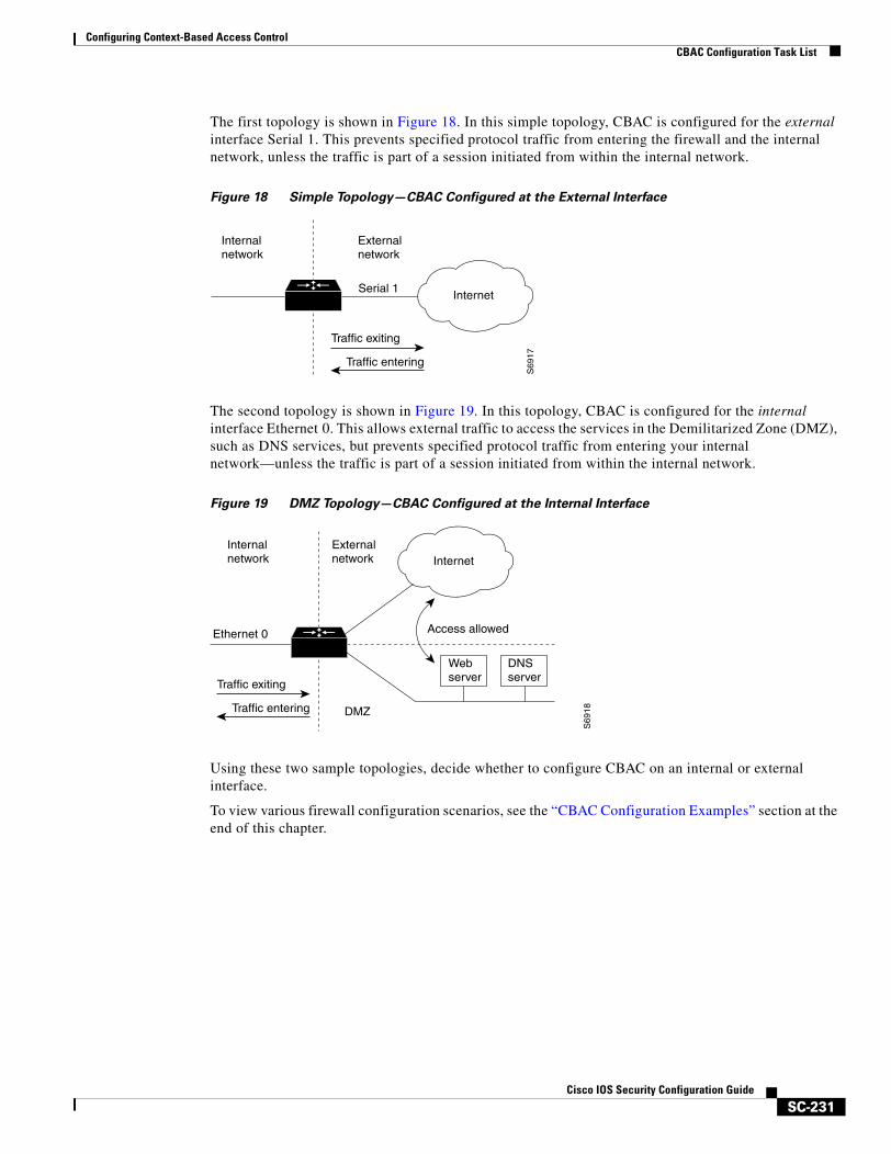
Configuring Context-Based Access ControlCBAC Configuration Task List
SC-231Cisco IOS Security Configuration Guide
The first topology is shown in Figure 18. In this simple topology, CBAC is configured for the external interface Serial 1. This prevents specified protocol traffic from entering the firewall and the internal network, unless the traffic is part of a session initiated from within the internal network.
Figure 18 Simple Topology—CBAC Configured at the External Interface
The second topology is shown in Figure 19. In this topology, CBAC is configured for the internal interface Ethernet 0. This allows external traffic to access the services in the Demilitarized Zone (DMZ), such as DNS services, but prevents specified protocol traffic from entering your internal network—unless the traffic is part of a session initiated from within the internal network.
Figure 19 DMZ Topology—CBAC Configured at the Internal Interface
Using these two sample topologies, decide whether to configure CBAC on an internal or external interface.
To view various firewall configuration scenarios, see the “CBAC Configuration Examples” section at the end of this chapter.
Internalnetwork
S69
17
Externalnetwork
InternetSerial 1
Traffic exiting
Traffic entering
Internalnetwork
Ethernet 0
S69
18
Externalnetwork
DMZ
Internet
Access allowed
Webserver
DNSserver
Traffic exiting
Traffic entering
Configuring Context-Based Access ControlCBAC Configuration Task List
SC-232Cisco IOS Security Configuration Guide
Configuring IP Access Lists at the InterfaceFor CBAC to work properly, you need to make sure that you have IP access lists configured appropriately at the interface.
Follow these three general rules when evaluating your IP access lists at the firewall:
• Start with a basic configuration.
If you try to configure access lists without a good understanding of how access lists work, you might inadvertently introduce security risks to the firewall and to the protected network. You should be sure you understand what access lists do before you configure your firewall. For more information about access control lists, refer to the “Access Control Lists: Overview and Guidelines” chapter.
A basic initial configuration allows all network traffic to flow from the protected networks to the unprotected networks, while blocking network traffic from any unprotected networks.
• Permit CBAC traffic to leave the network through the firewall.
All access lists that evaluate traffic leaving the protected network should permit traffic that will be inspected by CBAC. For example, if Telnet will be inspected by CBAC, then Telnet traffic should be permitted on all access lists that apply to traffic leaving the network.
• Use extended access lists to deny CBAC return traffic entering the network through the firewall.
For temporary openings to be created in an access list, the access list must be an extended access list. So wherever you have access lists that will be applied to returning traffic, you must use extended access lists. The access lists should deny CBAC return traffic because CBAC will open up temporary holes in the access lists. (You want traffic to be normally blocked when it enters your network.)
Note If your firewall only has two connections, one to the internal network and one to the external network, using all inbound access lists works well because packets are stopped before they get a chance to affect the router itself.
This section contains the following sections:
• Basic Configuration
• External Interface
• Internal Interface
Basic Configuration
The first time you configure the Cisco IOS Firewall, it is helpful to start with a basic access list configuration that makes the operation of the firewall easy to understand without compromising security. The basic configuration allows all network traffic from the protected networks access to the unprotected networks, while blocking all network traffic (with some exceptions) from the unprotected networks to the protected networks.
Any firewall configuration depends on your site security policy. If the basic configuration does not meet your initial site security requirements, configure the firewall to meet your policy. If you are unfamiliar with that policy or need help with the configuration, contact your network administration group for assistance. For additional guidelines on configuring a firewall, refer to the “Other Guidelines for Configuring a Firewall” section in this chapter.
Configuring Context-Based Access ControlCBAC Configuration Task List
SC-233Cisco IOS Security Configuration Guide
Use the following guidelines for configuring the initial firewall access lists:
• Do not configure an access list for traffic from the protected networks to the unprotected networks, meaning that all traffic from the protected networks can flow through the interface.
This helps to simplify firewall management by reducing the number of access lists applied at the interfaces. Of course this assumes a high level of trust for the users on the protected networks, and it assumes there are no malicious users on the protected networks who might launch attacks from the “inside.” You can fine tune network access for users on the protected networks as you gain experience with access list configuration and the operation of the firewall.
• Configure an access list that includes entries permitting certain ICMP traffic from unprotected networks.
While an access list that denies all IP traffic not part of a connection inspected by CBAC seems most secure, it is not practical for normal operation of the router. The router expects to see ICMP traffic from other routers in the network. Additionally, ICMP traffic is not inspected by CBAC, meaning specific entries are needed in the access list to permit return traffic for ICMP commands. For example, a user on a protected network uses the ping command to get the status of a host on an unprotected network; without entries in the access list that permit echo reply messages, the user on the protected network gets no response to the ping command.
Include access list entries to permit the following ICMP messages:
• Add an access list entry denying any network traffic from a source address matching an address on the protected network.
This is known as anti-spoofing protection because it prevents traffic from an unprotected network from assuming the identity of a device on the protected network.
• Add an entry denying broadcast messages with a source address of 255.255.255.255.
This entry helps to prevent broadcast attacks.
• By default, the last entry in an extended access list is an implicit denial of all IP traffic not specifically allowed by other entries in the access list.
Although this is the default setting, this final deny statement is not shown by default in an access list. Optionally, you can add an entry to the access list denying IP traffic with any source or destination address with no undesired effects.
For complete information about how to configure IP access lists, refer to the “Configuring IP Services” chapter of the Cisco IOS IP Configuration Guide.
For tips on applying access lists at an external or internal interface, review the sections “External Interface” and “Internal Interface” in this chapter.
Message Description
echo reply Outgoing ping commands require echo-reply messages to come back.
time-exceeded Outgoing traceroute commands require time-exceeded messages to come back.
packet-too-big Path MTU discovery requires “too-big” messages to come back.
traceroute Allow an incoming traceroute.
unreachable Permit all “unreachable” messages to come back. If a router cannot forward or deliver a datagram, it sends an ICMP unreachable message back to the source and drops the datagram.
Configuring Context-Based Access ControlCBAC Configuration Task List
SC-234Cisco IOS Security Configuration Guide
External Interface
Here are some guidelines for your access lists when you will be configuring CBAC on an external interface:
• If you have an outbound IP access list at the external interface, the access list can be a standard or extended access list. This outbound access list should permit traffic that you want to be inspected by CBAC. If traffic is not permitted, it will not be inspected by CBAC, but will be simply dropped.
• The inbound IP access list at the external interface must be an extended access list. This inbound access list should deny traffic that you want to be inspected by CBAC. (CBAC will create temporary openings in this inbound access list as appropriate to permit only return traffic that is part of a valid, existing session.)
• For complete information about how to configure IP access lists, refer to the “Configuring IP Services” chapter of the Cisco IOS IP Configuration Guide.
Internal Interface
Here are some tips for your access lists when you will be configuring CBAC on an internal interface:
• If you have an inbound IP access list at the internal interface or an outbound IP access list at external interface(s), these access lists can be either a standard or extended access list. These access lists should permit traffic that you want to be inspected by CBAC. If traffic is not permitted, it will not be inspected by CBAC, but will be simply dropped.
• The outbound IP access list at the internal interface and the inbound IP access list at the external interface must be extended access lists. These outbound access lists should deny traffic that you want to be inspected by CBAC. (CBAC will create temporary openings in these outbound access lists as appropriate to permit only return traffic that is part of a valid, existing session.) You do not necessarily need to configure an extended access list at both the outbound internal interface and the inbound external interface, but at least one is necessary to restrict traffic flowing through the firewall into the internal protected network.
• For complete information about how to configure IP access lists, refer to the “Configuring IP Services” chapter of the Cisco IOS IP Configuration Guide.
Configuring Global Timeouts and ThresholdsCBAC uses timeouts and thresholds to determine how long to manage state information for a session, and to determine when to drop sessions that do not become fully established. These timeouts and thresholds apply globally to all sessions.
You can use the default timeout and threshold values, or you can change to values more suitable to your security requirements. You should make any changes to the timeout and threshold values before you continue configuring CBAC.
Note If you want to enable the more aggressive TCP host-specific denial-of-service prevention that includes the blocking of connection initiation to a host, you must set the block-time specified in the ip inspect tcp max-incomplete host command (see the last row in Table 18).
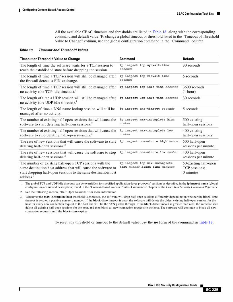
Configuring Context-Based Access ControlCBAC Configuration Task List
SC-235Cisco IOS Security Configuration Guide
All the available CBAC timeouts and thresholds are listed in Table 18, along with the corresponding command and default value. To change a global timeout or threshold listed in the “Timeout of Threshold Value to Change” column, use the global configuration command in the “Command” column:
To reset any threshold or timeout to the default value, use the no form of the command in Table 18.
Table 18 Timeout and Threshold Values
Timeout or Threshold Value to Change Command Default
The length of time the software waits for a TCP session to reach the established state before dropping the session.
ip inspect tcp synwait-time seconds
30 seconds
The length of time a TCP session will still be managed after the firewall detects a FIN-exchange.
ip inspect tcp finwait-time seconds
5 seconds
The length of time a TCP session will still be managed after no activity (the TCP idle timeout).1
1. The global TCP and UDP idle timeouts can be overridden for specified application-layer protocols’ sessions as described in the ip inspect name (global configuration) command description, found in the “Context-Based Access Control Commands” chapter of the Cisco IOS Security Command Reference.
ip inspect tcp idle-time seconds 3600 seconds (1 hour)
The length of time a UDP session will still be managed after no activity (the UDP idle timeout).1
ip inspect udp idle-time seconds 30 seconds
The length of time a DNS name lookup session will still be managed after no activity.
ip inspect dns-timeout seconds 5 seconds
The number of existing half-open sessions that will cause the software to start deleting half-open sessions.2
2. See the following section, “Half-Open Sessions,” for more information.
ip inspect max-incomplete high number
500 existing half-open sessions
The number of existing half-open sessions that will cause the software to stop deleting half-open sessions.2
ip inspect max-incomplete low number
400 existing half-open sessions
The rate of new sessions that will cause the software to start deleting half-open sessions.2
ip inspect one-minute high number 500 half-open sessions per minute
The rate of new sessions that will cause the software to stop deleting half-open sessions.2
ip inspect one-minute low number 400 half-open sessions per minute
The number of existing half-open TCP sessions with the same destination host address that will cause the software to start dropping half-open sessions to the same destination host address.3
3. Whenever the max-incomplete host threshold is exceeded, the software will drop half-open sessions differently depending on whether the block-time timeout is zero or a positive non-zero number. If the block-time timeout is zero, the software will delete the oldest existing half-open session for the host for every new connection request to the host and will let the SYN packet through. If the block-time timeout is greater than zero, the software will delete all existing half-open sessions for the host, and then block all new connection requests to the host. The software will continue to block all new connection requests until the block-time expires.
ip inspect tcp max-incomplete host number block-time minutes
50 existing half-open TCP sessions; 0 minutes
Configuring Context-Based Access ControlCBAC Configuration Task List
SC-236Cisco IOS Security Configuration Guide
Half-Open Sessions
An unusually high number of half-open sessions (either absolute or measured as the arrival rate) could indicate that a denial-of-service attack is occurring. For TCP, “half-open” means that the session has not reached the established state—the TCP three-way handshake has not yet been completed. For UDP, “half-open” means that the firewall has detected no return traffic.
CBAC measures both the total number of existing half-open sessions and the rate of session establishment attempts. Both TCP and UDP half-open sessions are counted in the total number and rate measurements. Rate measurements are made several times per minute.
When the number of existing half-open sessions rises above a threshold (the max-incomplete high number), the software will delete half-open sessions as required to accommodate new connection requests. The software will continue to delete half-open requests as necessary, until the number of existing half-open sessions drops below another threshold (the max-incomplete low number).
When the rate of new connection attempts rises above a threshold (the one-minute high number), the software will delete half-open sessions as required to accommodate new connection attempts. The software will continue to delete half-open sessions as necessary, until the rate of new connection attempts drops below another threshold (the one-minute low number). The rate thresholds are measured as the number of new session connection attempts detected in the last one-minute sample period.
Defining an Inspection RuleAfter you configure global timeouts and thresholds, you must define an inspection rule. This rule specifies what IP traffic (which application-layer protocols) will be inspected by CBAC at an interface.
Normally, you define only one inspection rule. The only exception might occur if you want to enable CBAC in two directions as described earlier in the section “When and Where to Configure CBAC.” For CBAC configured in both directions at a single firewall interface, you should configure two rules, one for each direction.
An inspection rule should specify each desired application-layer protocol as well as generic TCP or generic UDP if desired. The inspection rule consists of a series of statements each listing a protocol and specifying the same inspection rule name.
Inspection rules include options for controlling alert and audit trail messages and for checking IP packet fragmentation.
To define an inspection rule, follow the instructions in the following sections:
• Configuring Application-Layer Protocol Inspection
• Configuring Generic TCP and UDP Inspection
Configuring Application-Layer Protocol Inspection
This section provides instructions for configuring CBAC with the following inspection information:
• Configuring Application-Layer Protocols
• Configuring Java Blocking
• Configuring IP Packet Fragmentation Inspection
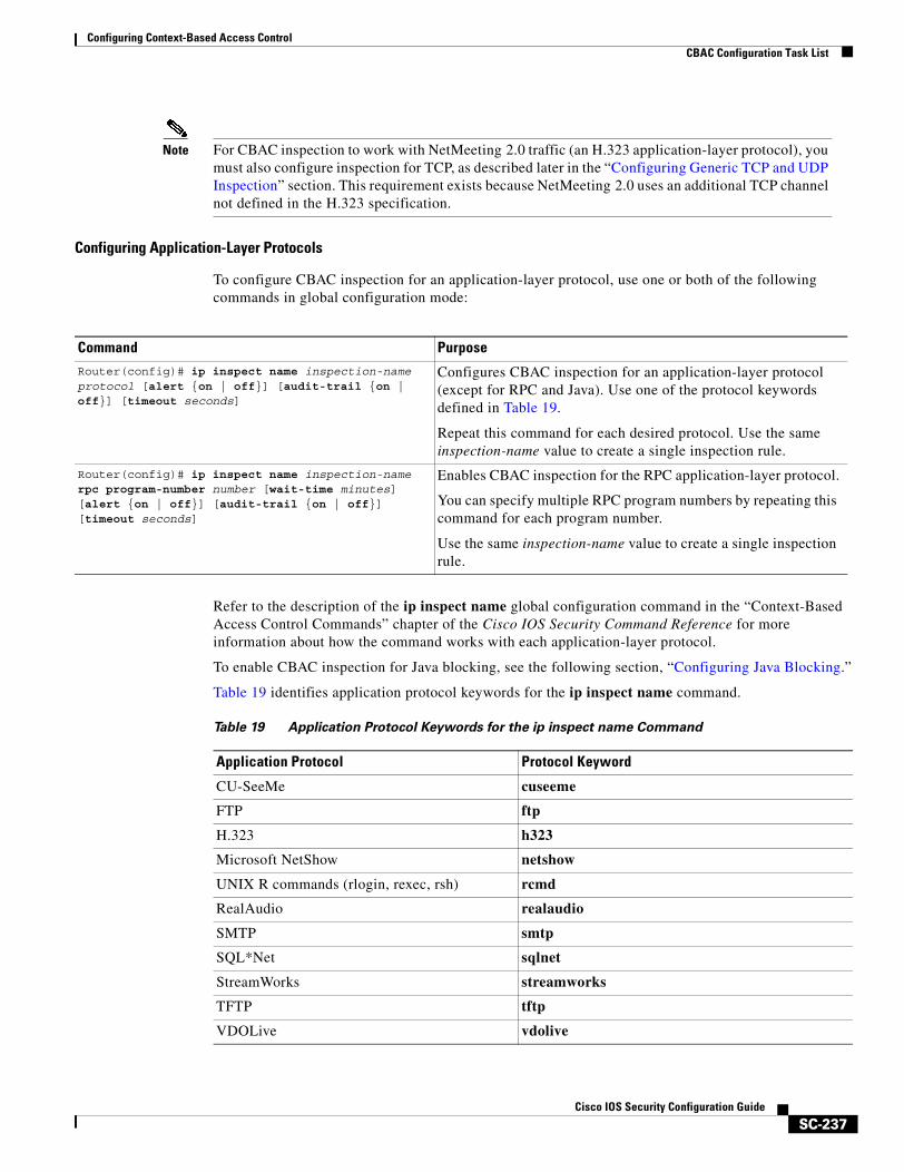
Configuring Context-Based Access ControlCBAC Configuration Task List
SC-237Cisco IOS Security Configuration Guide
Note For CBAC inspection to work with NetMeeting 2.0 traffic (an H.323 application-layer protocol), you must also configure inspection for TCP, as described later in the “Configuring Generic TCP and UDP Inspection” section. This requirement exists because NetMeeting 2.0 uses an additional TCP channel not defined in the H.323 specification.
Configuring Application-Layer Protocols
To configure CBAC inspection for an application-layer protocol, use one or both of the following commands in global configuration mode:
Refer to the description of the ip inspect name global configuration command in the “Context-Based Access Control Commands” chapter of the Cisco IOS Security Command Reference for more information about how the command works with each application-layer protocol.
To enable CBAC inspection for Java blocking, see the following section, “Configuring Java Blocking.”
Table 19 identifies application protocol keywords for the ip inspect name command.
Command PurposeRouter(config)# ip inspect name inspection-name protocol [alert {on | off}] [audit-trail {on | off}] [timeout seconds]
Configures CBAC inspection for an application-layer protocol (except for RPC and Java). Use one of the protocol keywords defined in Table 19.
Repeat this command for each desired protocol. Use the same inspection-name value to create a single inspection rule.
Router(config)# ip inspect name inspection-name rpc program-number number [wait-time minutes] [alert {on | off}] [audit-trail {on | off}] [timeout seconds]
Enables CBAC inspection for the RPC application-layer protocol.
You can specify multiple RPC program numbers by repeating this command for each program number.
Use the same inspection-name value to create a single inspection rule.
Table 19 Application Protocol Keywords for the ip inspect name Command
Application Protocol Protocol Keyword
CU-SeeMe cuseeme
FTP ftp
H.323 h323
Microsoft NetShow netshow
UNIX R commands (rlogin, rexec, rsh) rcmd
RealAudio realaudio
SMTP smtp
SQL*Net sqlnet
StreamWorks streamworks
TFTP tftp
VDOLive vdolive
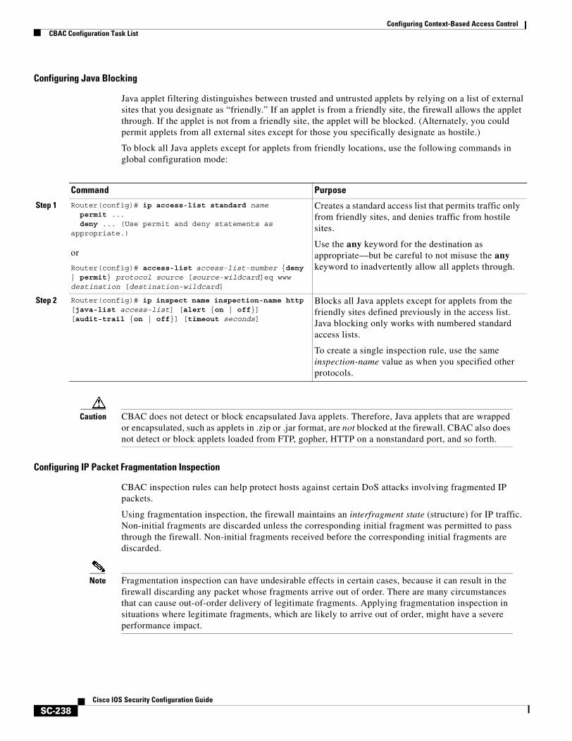
Configuring Context-Based Access ControlCBAC Configuration Task List
SC-238Cisco IOS Security Configuration Guide
Configuring Java Blocking
Java applet filtering distinguishes between trusted and untrusted applets by relying on a list of external sites that you designate as “friendly.” If an applet is from a friendly site, the firewall allows the applet through. If the applet is not from a friendly site, the applet will be blocked. (Alternately, you could permit applets from all external sites except for those you specifically designate as hostile.)
To block all Java applets except for applets from friendly locations, use the following commands in global configuration mode:
Caution CBAC does not detect or block encapsulated Java applets. Therefore, Java applets that are wrapped or encapsulated, such as applets in .zip or .jar format, are not blocked at the firewall. CBAC also does not detect or block applets loaded from FTP, gopher, HTTP on a nonstandard port, and so forth.
Configuring IP Packet Fragmentation Inspection
CBAC inspection rules can help protect hosts against certain DoS attacks involving fragmented IP packets.
Using fragmentation inspection, the firewall maintains an interfragment state (structure) for IP traffic. Non-initial fragments are discarded unless the corresponding initial fragment was permitted to pass through the firewall. Non-initial fragments received before the corresponding initial fragments are discarded.
Note Fragmentation inspection can have undesirable effects in certain cases, because it can result in the firewall discarding any packet whose fragments arrive out of order. There are many circumstances that can cause out-of-order delivery of legitimate fragments. Applying fragmentation inspection in situations where legitimate fragments, which are likely to arrive out of order, might have a severe performance impact.
Command Purpose
Step 1 Router(config)# ip access-list standard namepermit ...deny ... (Use permit and deny statements as
appropriate.)
or
Router(config)# access-list access-list-number {deny | permit} protocol source [source-wildcard]eq www destination [destination-wildcard]
Creates a standard access list that permits traffic only from friendly sites, and denies traffic from hostile sites.
Use the any keyword for the destination as appropriate—but be careful to not misuse the any keyword to inadvertently allow all applets through.
Step 2 Router(config)# ip inspect name inspection-name http [java-list access-list] [alert {on | off}] [audit-trail {on | off}] [timeout seconds]
Blocks all Java applets except for applets from the friendly sites defined previously in the access list. Java blocking only works with numbered standard access lists.
To create a single inspection rule, use the same inspection-name value as when you specified other protocols.
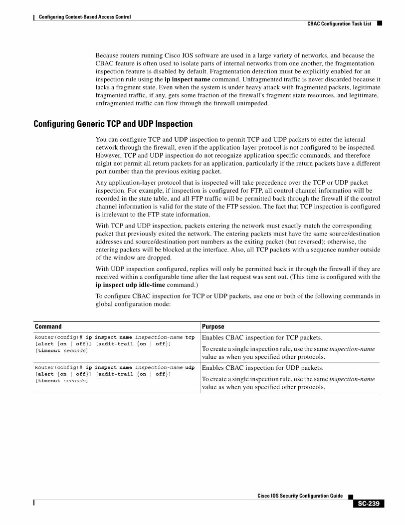
Configuring Context-Based Access ControlCBAC Configuration Task List
SC-239Cisco IOS Security Configuration Guide
Because routers running Cisco IOS software are used in a large variety of networks, and because the CBAC feature is often used to isolate parts of internal networks from one another, the fragmentation inspection feature is disabled by default. Fragmentation detection must be explicitly enabled for an inspection rule using the ip inspect name command. Unfragmented traffic is never discarded because it lacks a fragment state. Even when the system is under heavy attack with fragmented packets, legitimate fragmented traffic, if any, gets some fraction of the firewall's fragment state resources, and legitimate, unfragmented traffic can flow through the firewall unimpeded.
Configuring Generic TCP and UDP Inspection
You can configure TCP and UDP inspection to permit TCP and UDP packets to enter the internal network through the firewall, even if the application-layer protocol is not configured to be inspected. However, TCP and UDP inspection do not recognize application-specific commands, and therefore might not permit all return packets for an application, particularly if the return packets have a different port number than the previous exiting packet.
Any application-layer protocol that is inspected will take precedence over the TCP or UDP packet inspection. For example, if inspection is configured for FTP, all control channel information will be recorded in the state table, and all FTP traffic will be permitted back through the firewall if the control channel information is valid for the state of the FTP session. The fact that TCP inspection is configured is irrelevant to the FTP state information.
With TCP and UDP inspection, packets entering the network must exactly match the corresponding packet that previously exited the network. The entering packets must have the same source/destination addresses and source/destination port numbers as the exiting packet (but reversed); otherwise, the entering packets will be blocked at the interface. Also, all TCP packets with a sequence number outside of the window are dropped.
With UDP inspection configured, replies will only be permitted back in through the firewall if they are received within a configurable time after the last request was sent out. (This time is configured with the ip inspect udp idle-time command.)
To configure CBAC inspection for TCP or UDP packets, use one or both of the following commands in global configuration mode:
Command PurposeRouter(config)# ip inspect name inspection-name tcp [alert {on | off}] [audit-trail {on | off}] [timeout seconds]
Enables CBAC inspection for TCP packets.
To create a single inspection rule, use the same inspection-name value as when you specified other protocols.
Router(config)# ip inspect name inspection-name udp [alert {on | off}] [audit-trail {on | off}] [timeout seconds]
Enables CBAC inspection for UDP packets.
To create a single inspection rule, use the same inspection-name value as when you specified other protocols.
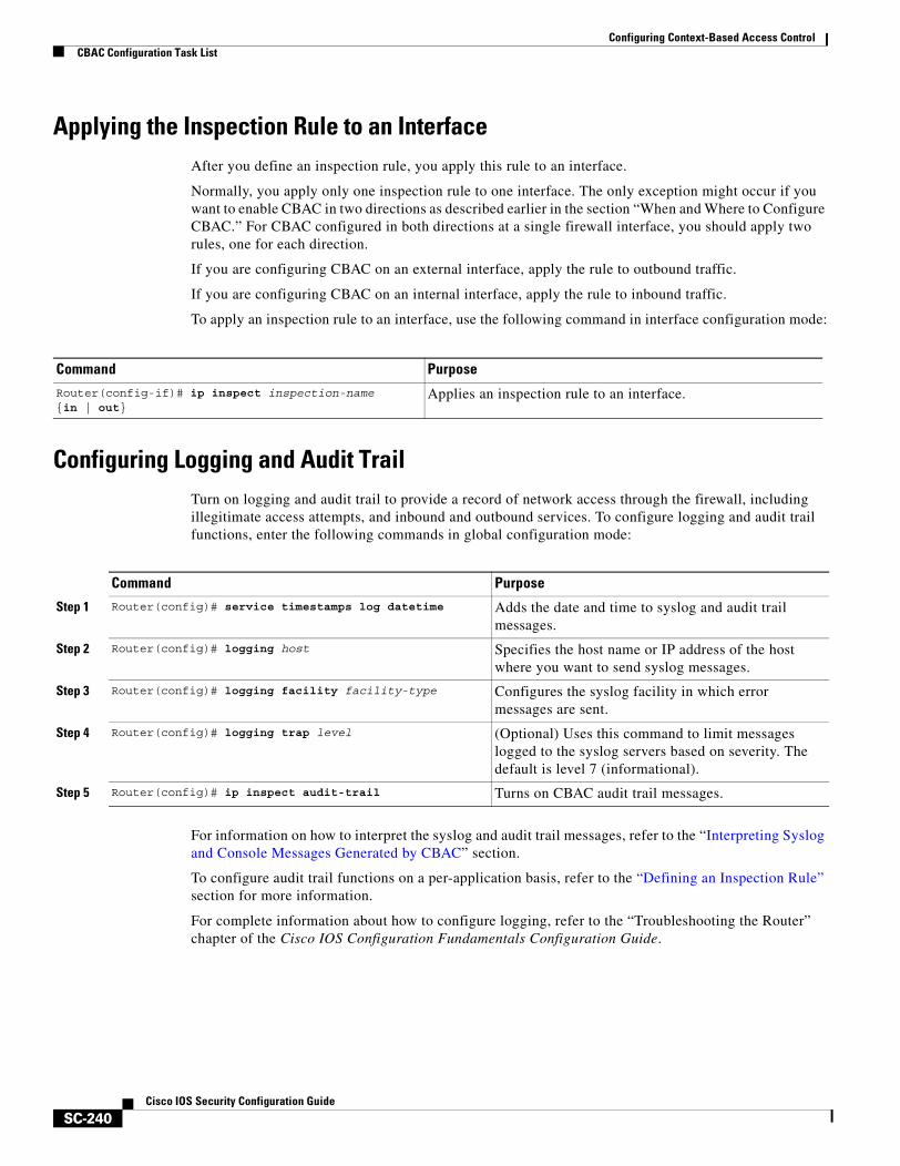
Configuring Context-Based Access ControlCBAC Configuration Task List
SC-240Cisco IOS Security Configuration Guide
Applying the Inspection Rule to an InterfaceAfter you define an inspection rule, you apply this rule to an interface.
Normally, you apply only one inspection rule to one interface. The only exception might occur if you want to enable CBAC in two directions as described earlier in the section “When and Where to Configure CBAC.” For CBAC configured in both directions at a single firewall interface, you should apply two rules, one for each direction.
If you are configuring CBAC on an external interface, apply the rule to outbound traffic.
If you are configuring CBAC on an internal interface, apply the rule to inbound traffic.
To apply an inspection rule to an interface, use the following command in interface configuration mode:
Configuring Logging and Audit TrailTurn on logging and audit trail to provide a record of network access through the firewall, including illegitimate access attempts, and inbound and outbound services. To configure logging and audit trail functions, enter the following commands in global configuration mode:
For information on how to interpret the syslog and audit trail messages, refer to the “Interpreting Syslog and Console Messages Generated by CBAC” section.
To configure audit trail functions on a per-application basis, refer to the “Defining an Inspection Rule” section for more information.
For complete information about how to configure logging, refer to the “Troubleshooting the Router” chapter of the Cisco IOS Configuration Fundamentals Configuration Guide.
Command Purpose
Router(config-if)# ip inspect inspection-name {in | out}
Applies an inspection rule to an interface.
Command Purpose
Step 1 Router(config)# service timestamps log datetime Adds the date and time to syslog and audit trail messages.
Step 2 Router(config)# logging host Specifies the host name or IP address of the host where you want to send syslog messages.
Step 3 Router(config)# logging facility facility-type Configures the syslog facility in which error messages are sent.
Step 4 Router(config)# logging trap level (Optional) Uses this command to limit messages logged to the syslog servers based on severity. The default is level 7 (informational).
Step 5 Router(config)# ip inspect audit-trail Turns on CBAC audit trail messages.
Configuring Context-Based Access ControlCBAC Configuration Task List
SC-241Cisco IOS Security Configuration Guide
Other Guidelines for Configuring a FirewallAs with all networking devices, you should always protect access into the firewall by configuring passwords as described in the “Configuring Passwords and Privileges” chapter. You should also consider configuring user authentication, authorization, and accounting as described in the “Authentication, Authorization, and Accounting (AAA)” part of this guide.
You should also consider the following recommendations:
• When setting passwords for privileged access to the firewall, use the enable secret command rather than the enable password command, which does not have as strong an encryption algorithm.
• Put a password on the console port. In authentication, authorization, and accounting (AAA) environments, use the same authentication for the console as for elsewhere. In a non-AAA environment, at a minimum configure the login and password password commands.
• Think about access control before you connect a console port to the network in any way, including attaching a modem to the port. Be aware that a break on the console port might give total control of the firewall, even with access control configured.
• Apply access lists and password protection to all virtual terminal ports. Use access lists to limit who can Telnet into your router.
• Do not enable any local service (such as SNMP or NTP) that you do not use. Cisco Discovery Protocol (CDP) and Network Time Protocol (NTP) are on by default, and you should turn these off if you do not need them.
To turn off CDP, enter the no cdp run global configuration command. To turn off NTP, enter the ntp disable interface configuration command on each interface not using NTP.
If you must run NTP, configure NTP only on required interfaces, and configure NTP to listen only to certain peers.
Any enabled service could present a potential security risk. A determined, hostile party might be able to find creative ways to misuse the enabled services to access the firewall or the network.
For local services that are enabled, protect against misuse. Protect by configuring the services to communicate only with specific peers, and protect by configuring access lists to deny packets for the services at specific interfaces.
• Protect against spoofing: protect the networks on both sides of the firewall from being spoofed from the other side. You could protect against spoofing by configuring input access lists at all interfaces to pass only traffic from expected source addresses, and to deny all other traffic.
You should also disable source routing. For IP, enter the no ip source-route global configuration command. Disabling source routing at all routers can also help prevent spoofing.
You should also disable minor services. For IP, enter the no service tcp-small-servers and no service udp-small-servers global configuration commands. In Cisco IOS Release 12.0 and later, these services are disabled by default.
• Prevent the firewall from being used as a relay by configuring access lists on any asynchronous Telnet ports.
• Normally, you should disable directed broadcasts for all applicable protocols on your firewall and on all your other routers. For IP, use the no ip directed-broadcast command. Rarely, some IP networks do require directed broadcasts; if this is the case, do not disable directed broadcasts.
Directed broadcasts can be misused to multiply the power of denial-of-service attacks, because every denial-of-service packet sent is broadcast to every host on a subnet. Furthermore, some hosts have other intrinsic security risks present when handling broadcasts.
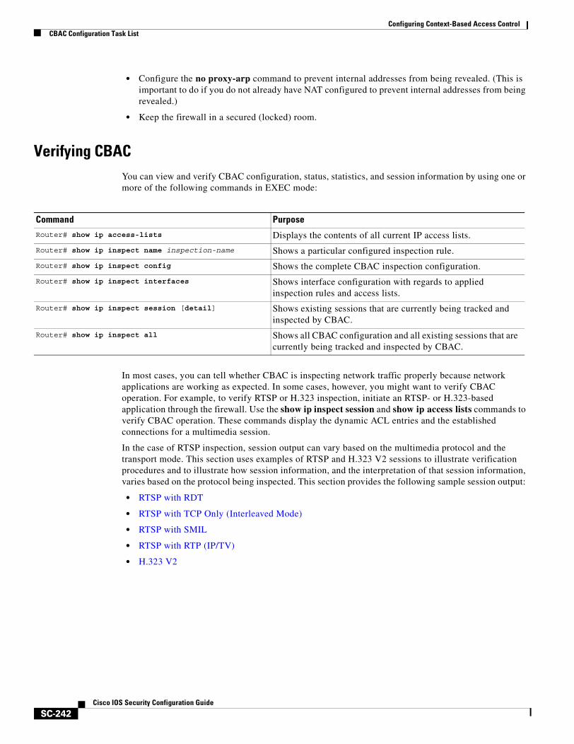
Configuring Context-Based Access ControlCBAC Configuration Task List
SC-242Cisco IOS Security Configuration Guide
• Configure the no proxy-arp command to prevent internal addresses from being revealed. (This is important to do if you do not already have NAT configured to prevent internal addresses from being revealed.)
• Keep the firewall in a secured (locked) room.
Verifying CBACYou can view and verify CBAC configuration, status, statistics, and session information by using one or more of the following commands in EXEC mode:
In most cases, you can tell whether CBAC is inspecting network traffic properly because network applications are working as expected. In some cases, however, you might want to verify CBAC operation. For example, to verify RTSP or H.323 inspection, initiate an RTSP- or H.323-based application through the firewall. Use the show ip inspect session and show ip access lists commands to verify CBAC operation. These commands display the dynamic ACL entries and the established connections for a multimedia session.
In the case of RTSP inspection, session output can vary based on the multimedia protocol and the transport mode. This section uses examples of RTSP and H.323 V2 sessions to illustrate verification procedures and to illustrate how session information, and the interpretation of that session information, varies based on the protocol being inspected. This section provides the following sample session output:
• RTSP with RDT
• RTSP with TCP Only (Interleaved Mode)
• RTSP with SMIL
• RTSP with RTP (IP/TV)
• H.323 V2
Command Purpose
Router# show ip access-lists Displays the contents of all current IP access lists.
Router# show ip inspect name inspection-name Shows a particular configured inspection rule.
Router# show ip inspect config Shows the complete CBAC inspection configuration.
Router# show ip inspect interfaces Shows interface configuration with regards to applied inspection rules and access lists.
Router# show ip inspect session [detail] Shows existing sessions that are currently being tracked and inspected by CBAC.
Router# show ip inspect all Shows all CBAC configuration and all existing sessions that are currently being tracked and inspected by CBAC.
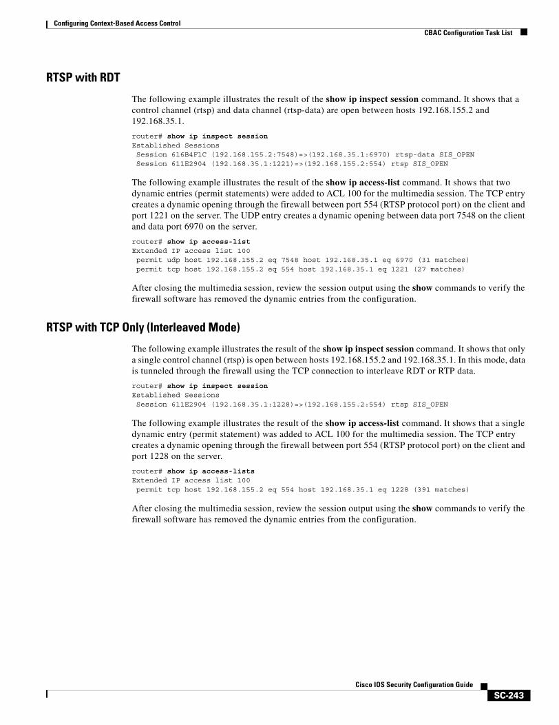
Configuring Context-Based Access ControlCBAC Configuration Task List
SC-243Cisco IOS Security Configuration Guide
RTSP with RDT
The following example illustrates the result of the show ip inspect session command. It shows that a control channel (rtsp) and data channel (rtsp-data) are open between hosts 192.168.155.2 and 192.168.35.1.
router# show ip inspect session Established SessionsSession 616B4F1C (192.168.155.2:7548)=>(192.168.35.1:6970) rtsp-data SIS_OPENSession 611E2904 (192.168.35.1:1221)=>(192.168.155.2:554) rtsp SIS_OPEN
The following example illustrates the result of the show ip access-list command. It shows that two dynamic entries (permit statements) were added to ACL 100 for the multimedia session. The TCP entry creates a dynamic opening through the firewall between port 554 (RTSP protocol port) on the client and port 1221 on the server. The UDP entry creates a dynamic opening between data port 7548 on the client and data port 6970 on the server.
router# show ip access-listExtended IP access list 100permit udp host 192.168.155.2 eq 7548 host 192.168.35.1 eq 6970 (31 matches)permit tcp host 192.168.155.2 eq 554 host 192.168.35.1 eq 1221 (27 matches)
After closing the multimedia session, review the session output using the show commands to verify the firewall software has removed the dynamic entries from the configuration.
RTSP with TCP Only (Interleaved Mode)
The following example illustrates the result of the show ip inspect session command. It shows that only a single control channel (rtsp) is open between hosts 192.168.155.2 and 192.168.35.1. In this mode, data is tunneled through the firewall using the TCP connection to interleave RDT or RTP data.
router# show ip inspect session Established SessionsSession 611E2904 (192.168.35.1:1228)=>(192.168.155.2:554) rtsp SIS_OPEN
The following example illustrates the result of the show ip access-list command. It shows that a single dynamic entry (permit statement) was added to ACL 100 for the multimedia session. The TCP entry creates a dynamic opening through the firewall between port 554 (RTSP protocol port) on the client and port 1228 on the server.
router# show ip access-lists Extended IP access list 100permit tcp host 192.168.155.2 eq 554 host 192.168.35.1 eq 1228 (391 matches)
After closing the multimedia session, review the session output using the show commands to verify the firewall software has removed the dynamic entries from the configuration.
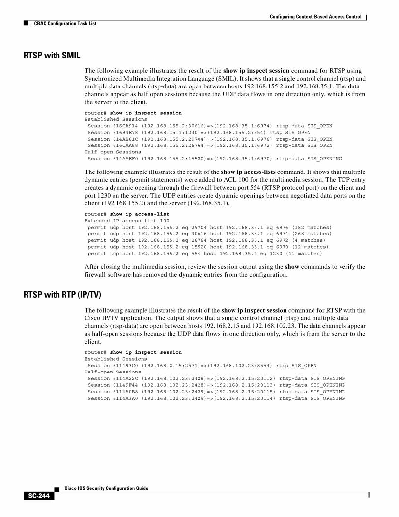
Configuring Context-Based Access ControlCBAC Configuration Task List
SC-244Cisco IOS Security Configuration Guide
RTSP with SMIL
The following example illustrates the result of the show ip inspect session command for RTSP using Synchronized Multimedia Integration Language (SMIL). It shows that a single control channel (rtsp) and multiple data channels (rtsp-data) are open between hosts 192.168.155.2 and 192.168.35.1. The data channels appear as half open sessions because the UDP data flows in one direction only, which is from the server to the client.
router# show ip inspect session Established SessionsSession 616CA914 (192.168.155.2:30616)=>(192.168.35.1:6974) rtsp-data SIS_OPENSession 616B4E78 (192.168.35.1:1230)=>(192.168.155.2:554) rtsp SIS_OPENSession 614AB61C (192.168.155.2:29704)=>(192.168.35.1:6976) rtsp-data SIS_OPENSession 616CAA88 (192.168.155.2:26764)=>(192.168.35.1:6972) rtsp-data SIS_OPEN
Half-open SessionsSession 614AAEF0 (192.168.155.2:15520)=>(192.168.35.1:6970) rtsp-data SIS_OPENING
The following example illustrates the result of the show ip access-lists command. It shows that multiple dynamic entries (permit statements) were added to ACL 100 for the multimedia session. The TCP entry creates a dynamic opening through the firewall between port 554 (RTSP protocol port) on the client and port 1230 on the server. The UDP entries create dynamic openings between negotiated data ports on the client (192.168.155.2) and the server (192.168.35.1).
router# show ip access-list Extended IP access list 100permit udp host 192.168.155.2 eq 29704 host 192.168.35.1 eq 6976 (182 matches)permit udp host 192.168.155.2 eq 30616 host 192.168.35.1 eq 6974 (268 matches)permit udp host 192.168.155.2 eq 26764 host 192.168.35.1 eq 6972 (4 matches)permit udp host 192.168.155.2 eq 15520 host 192.168.35.1 eq 6970 (12 matches)permit tcp host 192.168.155.2 eq 554 host 192.168.35.1 eq 1230 (41 matches)
After closing the multimedia session, review the session output using the show commands to verify the firewall software has removed the dynamic entries from the configuration.
RTSP with RTP (IP/TV)
The following example illustrates the result of the show ip inspect session command for RTSP with the Cisco IP/TV application. The output shows that a single control channel (rtsp) and multiple data channels (rtsp-data) are open between hosts 192.168.2.15 and 192.168.102.23. The data channels appear as half-open sessions because the UDP data flows in one direction only, which is from the server to the client.
router# show ip inspect session Established SessionsSession 611493C0 (192.168.2.15:2571)=>(192.168.102.23:8554) rtsp SIS_OPEN
Half-open SessionsSession 6114A22C (192.168.102.23:2428)=>(192.168.2.15:20112) rtsp-data SIS_OPENINGSession 61149F44 (192.168.102.23:2428)=>(192.168.2.15:20113) rtsp-data SIS_OPENINGSession 6114A0B8 (192.168.102.23:2429)=>(192.168.2.15:20115) rtsp-data SIS_OPENINGSession 6114A3A0 (192.168.102.23:2429)=>(192.168.2.15:20114) rtsp-data SIS_OPENING
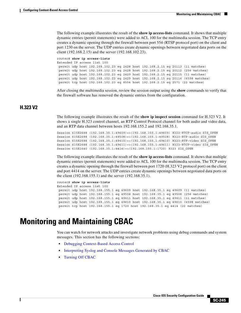
Configuring Context-Based Access ControlMonitoring and Maintaining CBAC
SC-245Cisco IOS Security Configuration Guide
The following example illustrates the result of the show ip access-lists command. It shows that multiple dynamic entries (permit statements) were added to ACL 100 for the multimedia session. The TCP entry creates a dynamic opening through the firewall between port 554 (RTSP protocol port) on the client and port 1230 on the server. The UDP entries create dynamic openings between negotiated data ports on the client (192.168.2.15) and the server (192.168.102.23).
router# show ip access-lists Extended IP access list 100permit udp host 192.168.102.23 eq 2428 host 192.168.2.15 eq 20113 (11 matches)permit udp host 192.168.102.23 eq 2428 host 192.168.2.15 eq 20112 (256 matches)permit udp host 192.168.102.23 eq 2429 host 192.168.2.15 eq 20115 (11 matches)permit udp host 192.168.102.23 eq 2429 host 192.168.2.15 eq 20114 (4598 matches)permit tcp host 192.168.102.23 eq 8554 host 192.168.2.15 eq 2571 (22 matches)
After closing the multimedia session, review the session output using the show commands to verify that the firewall software has removed the dynamic entries from the configuration.
H.323 V2
The following example illustrates the result of the show ip inspect session command for H.323 V2. It shows a single H.323 control channel, an RTP Control Protocol channel for both audio and video data, and an RTP data channel between hosts 192.168.155.2 and 192.168.35.1.
Session 615E2688 (192.168.35.1:49609)=>(192.168.155.1:49609) H323-RTCP-audio SIS_OPEN Session 615E2688 (192.168.35.1:49508)=>(192.168.155.1:49508) H323-RTP-audio SIS_OPEN Session 615E2688 (192.168.35.1:49410)=>(192.168.155.1:49410) H323-RTP-video SIS_OPEN Session 615E2688 (192.168.35.1:49611)=>(192.168.155.1:49611) H323-RTCP-video SIS_OPEN Session 615E1640 (192.168.35.1:4414)=>(192.168.155.1:1720) H323 SIS_OPEN
The following example illustrates the result of the show ip access-lists command. It shows that multiple dynamic entries (permit statements) were added to ACL 100 for the multimedia session. The TCP entry creates a dynamic opening through the firewall between port 1720 (H.323 V2 protocol port) on the client and port 4414 on the server. The UDP entries create dynamic openings between negotiated data ports on the client (192.168.155.1) and the server (192.168.35.1).
router# show ip access-lists Extended IP access list 100permit udp host 192.168.155.1 eq 49609 host 192.168.35.1 eq 49609 (11 matches)permit udp host 192.168.155.1 eq 49508 host 192.168.35.1 eq 49508 (256 matches)permit udp host 192.168.155.1 eq 49411 host 192.168.35.1 eq 49411 (11 matches)permit udp host 192.168.155.1 eq 49610 host 192.168.35.1 eq 49610 (4598 matches)permit tcp host 192.168.155.1 eq 1720 host 192.168.35.1 eq 4414 (22 matches)
Monitoring and Maintaining CBACYou can watch for network attacks and investigate network problems using debug commands and system messages. This section has the following sections:
• Debugging Context-Based Access Control
• Interpreting Syslog and Console Messages Generated by CBAC
• Turning Off CBAC
Configuring Context-Based Access ControlMonitoring and Maintaining CBAC
SC-246Cisco IOS Security Configuration Guide
Debugging Context-Based Access ControlTo assist CBAC debugging, you can turn on audit trail messages that will be displayed on the console after each CBAC session closes. Audit trail information is also configurable on a per-application basis using the CBAC inspection rules.
To turn on audit trail messages, use the following command in global configuration mode:
If required, you can also use the CBAC debug commands listed in this section. (Debugging can be turned off for each of the commands in this section by using the no form of the command. To disable all debugging, use the privileged EXEC commands no debug all or undebug all.)
The following debug commands are available:
• Generic Debug Commands
• Transport Level Debug Commands
• Application Protocol Debug Commands
For a complete description of the debug commands, refer to the Cisco IOS Debug Command Reference.
Generic Debug Commands
You can use the following generic debug commands, entered in privileged EXEC mode:
Command Purpose
Router(config)# ip inspect audit-trail Turns on CBAC audit trail messages.
Command PurposeRouter# debug ip inspect function-trace Displays messages about software functions called by CBAC.
Router# debug ip inspect object-creation Displays messages about software objects being created by CBAC. Object creation corresponds to the beginning of CBAC-inspected sessions.
Router# debug ip inspect object-deletion Displays messages about software objects being deleted by CBAC. Object deletion corresponds to the closing of CBAC-inspected sessions.
Router# debug ip inspect events Displays messages about CBAC software events, including information about CBAC packet processing.
Router# debug ip inspect timers Displays messages about CBAC timer events such as when a CBAC idle timeout is reached.
Router# debug ip inspect detail Enables the detailed option, which can be used in combination with other options to get additional information.
Configuring Context-Based Access ControlMonitoring and Maintaining CBAC
SC-247Cisco IOS Security Configuration Guide
Transport Level Debug Commands
You can use the following transport-level debug commands, entered in privileged EXEC mode:
Application Protocol Debug Commands
You can use the following application protocol debug command, entered in privileged EXEC mode:
Table 20 identifies application protocol keywords for the debug ip inspect command.
Command PurposeRouter# debug ip inspect tcp Displays messages about CBAC-inspected TCP events,
including details about TCP packets.
Router# debug ip inspect udp Displays messages about CBAC-inspected UDP events, including details about UDP packets.
Command PurposeRouter# debug ip inspect protocol Displays messages about CBAC-inspected protocol events,
including details about the protocol’s packets.
Refer to Table 20 to determine the protocol keyword.
Table 20 Application Protocol Keywords for the debug ip inspect Command
Application Protocol Protocol Keyword
CU-SeeMe cuseeme
FTP commands and responses ftp-cmd
FTP token (enables tracing of the FTP tokens parsed) ftp-token
H.323 h323
HTTP (Java applets) http
Microsoft NetShow netshow
UNIX R commands (rlogin, rexec, rsh) rcmd
RealAudio realaudio
RPC rpc
SMTP smtp
SQL*Net sqlnet
StreamWorks streamworks
TFTP tftp
VDOLive vdolive
Configuring Context-Based Access ControlMonitoring and Maintaining CBAC
SC-248Cisco IOS Security Configuration Guide
Interpreting Syslog and Console Messages Generated by CBACCBAC provides syslog messages, console alert messages, and audit trail messages. These messages are useful because they can alert you to network attacks and because they provide an audit trail that provides details about sessions inspected by CBAC. While they are generally referred to as error messages, not all error messages indicate problems with your system.
Audit trail and alert information is configurable on a per-application basis using the CBAC inspection rules.
The following types of messages can be generated by CBAC:
• Denial-of-Service Attack Detection Error Messages
• SMTP Attack Detection Error Messages
• Java Blocking Error Messages
• FTP Error Messages
• Audit Trail Messages
For explanations and recommended actions related to the error messages mentioned in this section, refer to the Cisco IOS System Error Messages.
Denial-of-Service Attack Detection Error Messages
CBAC detects and blocks denial-of-service attacks and notifies you when denial-of-service attacks occur. Error messages such as the following may indicate that denial-of-service attacks have occurred:
%FW-4-ALERT_ON: getting aggressive, count (550/500) current 1-min rate: 250%FW-4-ALERT_OFF: calming down, count (0/400) current 1-min rate: 0
When %FW-4-ALERT_ON and %FW-4-ALERT_OFF error messages appear together, each “aggressive/calming” pair of messages indicates a separate attack. The preceding example shows one separate attack.
Error messages such as the following may indicate that a denial-of-service attack has occurred on a specific TCP host:
%FW-4-HOST_TCP_ALERT_ON: Max tcp half-open connections (50) exceeded for host 172.21.127.242.%FW-4-BLOCK_HOST: Blocking new TCP connections to host 172.21.127.242 for 2 minutes (half-open count 50 exceeded)%FW-4-UNBLOCK_HOST: New TCP connections to host 172.21.127.242 no longer blocked
SMTP Attack Detection Error Messages
CBAC detects and blocks SMTP attacks (illegal SMTP commands) and notifies you when SMTP attacks occur. Error messages such as the following may indicate that an SMTP attack has occurred:
%FW-4-SMTP_INVALID_COMMAND: Invalid SMTP command from initiator (192.168.12.3:52419)
CBAC also detects a limited number of SMTP attack signatures. A signature in a SYSLOG message indicates a possible attack against the protected network, such as the detection of illegal SMTP commands in a packet. Whenever a signature is detected, the connection will be reset.
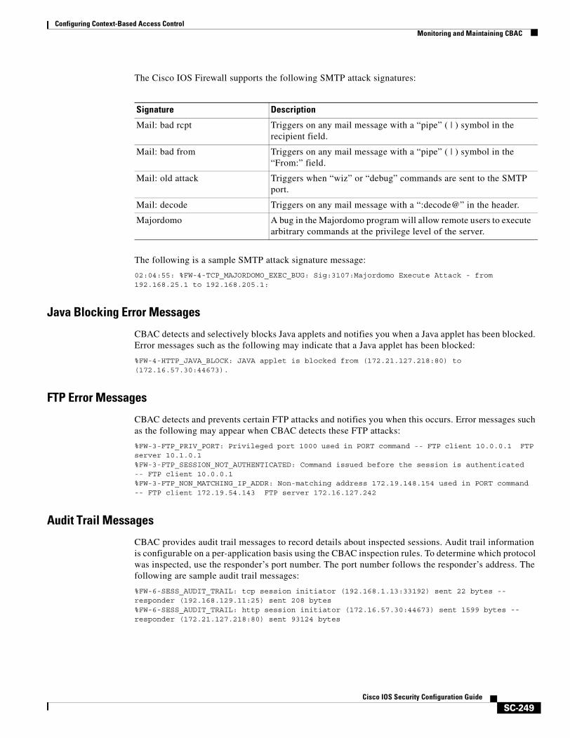
Configuring Context-Based Access ControlMonitoring and Maintaining CBAC
SC-249Cisco IOS Security Configuration Guide
The Cisco IOS Firewall supports the following SMTP attack signatures:
The following is a sample SMTP attack signature message:
02:04:55: %FW-4-TCP_MAJORDOMO_EXEC_BUG: Sig:3107:Majordomo Execute Attack - from 192.168.25.1 to 192.168.205.1:
Java Blocking Error Messages
CBAC detects and selectively blocks Java applets and notifies you when a Java applet has been blocked. Error messages such as the following may indicate that a Java applet has been blocked:
%FW-4-HTTP_JAVA_BLOCK: JAVA applet is blocked from (172.21.127.218:80) to(172.16.57.30:44673).
FTP Error Messages
CBAC detects and prevents certain FTP attacks and notifies you when this occurs. Error messages such as the following may appear when CBAC detects these FTP attacks:
%FW-3-FTP_PRIV_PORT: Privileged port 1000 used in PORT command -- FTP client 10.0.0.1 FTP server 10.1.0.1%FW-3-FTP_SESSION_NOT_AUTHENTICATED: Command issued before the session is authenticated -- FTP client 10.0.0.1%FW-3-FTP_NON_MATCHING_IP_ADDR: Non-matching address 172.19.148.154 used in PORT command -- FTP client 172.19.54.143 FTP server 172.16.127.242
Audit Trail Messages
CBAC provides audit trail messages to record details about inspected sessions. Audit trail information is configurable on a per-application basis using the CBAC inspection rules. To determine which protocol was inspected, use the responder’s port number. The port number follows the responder’s address. The following are sample audit trail messages:
%FW-6-SESS_AUDIT_TRAIL: tcp session initiator (192.168.1.13:33192) sent 22 bytes -- responder (192.168.129.11:25) sent 208 bytes%FW-6-SESS_AUDIT_TRAIL: http session initiator (172.16.57.30:44673) sent 1599 bytes -- responder (172.21.127.218:80) sent 93124 bytes
Signature Description
Mail: bad rcpt Triggers on any mail message with a “pipe” ( | ) symbol in the recipient field.
Mail: bad from Triggers on any mail message with a “pipe” ( | ) symbol in the “From:” field.
Mail: old attack Triggers when “wiz” or “debug” commands are sent to the SMTP port.
Mail: decode Triggers on any mail message with a “:decode@” in the header.
Majordomo A bug in the Majordomo program will allow remote users to execute arbitrary commands at the privilege level of the server.
Configuring Context-Based Access ControlCBAC Configuration Examples
SC-250Cisco IOS Security Configuration Guide
Turning Off CBACYou can turn off CBAC using the no ip inspect global configuration command.
Note The no ip inspect command removes all CBAC configuration entries and resets all CBAC global timeouts and thresholds to the defaults. All existing sessions are deleted and their associated access lists removed.
In most situations, turning off CBAC has no negative security impact because CBAC creates “permit” access lists. Without CBAC configured, no “permit” access lists are maintained. Therefore, no derived traffic (returning traffic or traffic from the data channels) can go through the firewall. The exception is SMTP and Java blocking. With CBAC turned off, unacceptable SMTP commands or Java applets may go through the firewall.
CBAC Configuration ExamplesThe following sections provide CBAC configuration examples:
• Ethernet Interface Configuration Example
• ATM Interface Configuration Example
• Remote Office to ISP Configuration Example
• Remote Office to Branch Office Configuration Example
• Two-Interface Branch Office Configuration Example
• Multiple-Interface Branch Office Configuration Example
The first example develops a CBAC inspection rule for specific protocols and a supporting access control list (ACL). This example focuses how to configure CBAC; it does not provide a complete router configuration and does not describe other elements of the configuration.
The next example develops a CBAC inspection rule for sites that might have remote traffic through an ATM interface. This example further illustrates on how to configure CBAC and emphasizes the application of the configuration rule at the interface, whatever that interface might be. This example does not provide a complete router configuration and does not describe other elements of the configuration.
The remote-office examples also focus on the firewall configuration but do not provide detailed descriptions of other configuration elements, such as the Basic Rate Interface (BRI) and dialer interface configurations.
Other examples provide more complete firewall configurations, further illustrating ways in which to apply CBAC.
In each example, configuring protocol inspection using CBAC has four components:
• Defining an access list with the appropriate permissions.
• Applying the ACL at an interface where you want to control access.
• Defining an inspection rule that includes the protocol that you want to inspect.
• Applying the inspection rule at an interface where you want to inspect traffic.
Configuring Context-Based Access ControlCBAC Configuration Examples
SC-251Cisco IOS Security Configuration Guide
Ethernet Interface Configuration ExampleThis example looks at each of these four components. For this example, CBAC is being configured to inspect RTSP and H.323 protocol traffic inbound from the protected network on a router with two Ethernet interfaces. Interface Ethernet1/0 is the protected network and interface Ethernet1/1 is the unprotected network. The security policy for the protected site uses access control lists (ACLs) to restrict inbound traffic on the unprotected interface to specific ICMP protocol traffic, denying inbound access for TCP and UDP protocol traffic. Inbound access for specific protocol traffic is provided through dynamic access lists, which are generated according to CBAC inspection rules.
ACL 100 denies TCP and UDP traffic from any source or destination while permitting specific ICMP protocol traffic. The final deny statement is not required, but is included for explicitness—the final entry in any ACL is an implicit denial of all IP protocol traffic.
Router(config)# access-list 100 deny tcp any any Router(config)# access-list 100 deny udp any any Router(config)# access-list 100 permit icmp any any echo-reply Router(config)# access-list 100 permit icmp any any time-exceeded Router(config)# access-list 100 permit icmp any any packet-too-big Router(config)# access-list 100 permit icmp any any traceroute Router(config)# access-list 100 permit icmp any any unreachable Router(config)# access-list 100 deny ip any any
ACL 100 is applied inbound at interface Ethernet1/1 to block all access from the unprotected network to the protected network.
Router(config)# interface Ethernet1/1 Router(config-if)# ip access-group 100 in
An inspection rule is created for “hqusers” that covers two protocols: RTSP and H.323.
Router(config)# ip inspect name hqusers rtsp Router(config)# ip inspect name hqusers h323
The inspection rule is applied inbound at interface Ethernet1/0 to inspect traffic from users on the protected network. When CBAC detects multimedia traffic from the protected network, CBAC creates dynamic entries in access list 100 to allow return traffic for multimedia sessions.
Router(config)# interface Ethernet1/0 Router(config-if)# ip inspect hqusers in
ATM Interface Configuration ExampleIn this example, CBAC inspection (firewall protection) is required against inbound traffic on an ATM interface. This example might apply to sites where local hosts require access to hosts or services on a remote network. The security policy for this site uses access control lists (ACLs) to restrict inbound traffic on the ATM interface to specific ICMP protocol traffic, denying inbound access for TCP and UDP protocol traffic. Inbound access for specific TCP and UDP protocol traffic is provided through dynamic access lists, which are generated according to CBAC inspection rules.
For information on how to select the interface on which to apply CBAC, refer to the “Picking an Interface: Internal or External” section.
Note For Frame Relay or ATM interfaces, you can apply CBAC inspection rules separately on each sub-interface, even though the subinterfaces are physically connected through one interface.
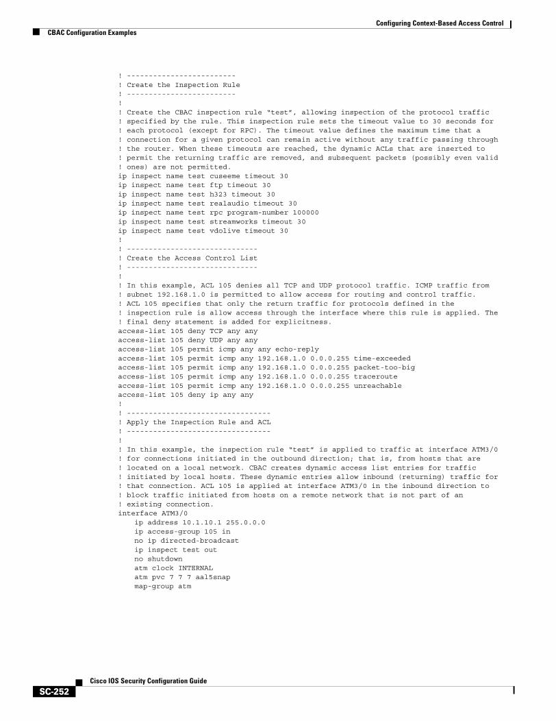
Configuring Context-Based Access ControlCBAC Configuration Examples
SC-252Cisco IOS Security Configuration Guide
! -------------------------! Create the Inspection Rule! -------------------------!! Create the CBAC inspection rule “test”, allowing inspection of the protocol traffic! specified by the rule. This inspection rule sets the timeout value to 30 seconds for! each protocol (except for RPC). The timeout value defines the maximum time that a! connection for a given protocol can remain active without any traffic passing through! the router. When these timeouts are reached, the dynamic ACLs that are inserted to! permit the returning traffic are removed, and subsequent packets (possibly even valid! ones) are not permitted. ip inspect name test cuseeme timeout 30ip inspect name test ftp timeout 30ip inspect name test h323 timeout 30ip inspect name test realaudio timeout 30ip inspect name test rpc program-number 100000ip inspect name test streamworks timeout 30ip inspect name test vdolive timeout 30! ! ------------------------------! Create the Access Control List! ------------------------------! ! In this example, ACL 105 denies all TCP and UDP protocol traffic. ICMP traffic from! subnet 192.168.1.0 is permitted to allow access for routing and control traffic.! ACL 105 specifies that only the return traffic for protocols defined in the ! inspection rule is allow access through the interface where this rule is applied. The! final deny statement is added for explicitness.access-list 105 deny TCP any anyaccess-list 105 deny UDP any anyaccess-list 105 permit icmp any any echo-replyaccess-list 105 permit icmp any 192.168.1.0 0.0.0.255 time-exceededaccess-list 105 permit icmp any 192.168.1.0 0.0.0.255 packet-too-bigaccess-list 105 permit icmp any 192.168.1.0 0.0.0.255 tracerouteaccess-list 105 permit icmp any 192.168.1.0 0.0.0.255 unreachableaccess-list 105 deny ip any any! ! ---------------------------------! Apply the Inspection Rule and ACL! ---------------------------------! ! In this example, the inspection rule “test” is applied to traffic at interface ATM3/0! for connections initiated in the outbound direction; that is, from hosts that are! located on a local network. CBAC creates dynamic access list entries for traffic! initiated by local hosts. These dynamic entries allow inbound (returning) traffic for! that connection. ACL 105 is applied at interface ATM3/0 in the inbound direction to! block traffic initiated from hosts on a remote network that is not part of an ! existing connection.interface ATM3/0
ip address 10.1.10.1 255.0.0.0ip access-group 105 inno ip directed-broadcastip inspect test outno shutdownatm clock INTERNALatm pvc 7 7 7 aal5snapmap-group atm
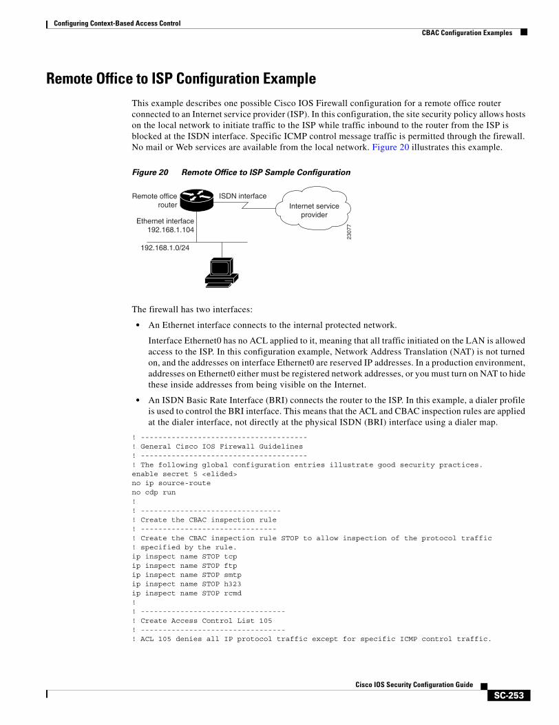
Configuring Context-Based Access ControlCBAC Configuration Examples
SC-253Cisco IOS Security Configuration Guide
Remote Office to ISP Configuration ExampleThis example describes one possible Cisco IOS Firewall configuration for a remote office router connected to an Internet service provider (ISP). In this configuration, the site security policy allows hosts on the local network to initiate traffic to the ISP while traffic inbound to the router from the ISP is blocked at the ISDN interface. Specific ICMP control message traffic is permitted through the firewall. No mail or Web services are available from the local network. Figure 20 illustrates this example.
Figure 20 Remote Office to ISP Sample Configuration
The firewall has two interfaces:
• An Ethernet interface connects to the internal protected network.
Interface Ethernet0 has no ACL applied to it, meaning that all traffic initiated on the LAN is allowed access to the ISP. In this configuration example, Network Address Translation (NAT) is not turned on, and the addresses on interface Ethernet0 are reserved IP addresses. In a production environment, addresses on Ethernet0 either must be registered network addresses, or you must turn on NAT to hide these inside addresses from being visible on the Internet.
• An ISDN Basic Rate Interface (BRI) connects the router to the ISP. In this example, a dialer profile is used to control the BRI interface. This means that the ACL and CBAC inspection rules are applied at the dialer interface, not directly at the physical ISDN (BRI) interface using a dialer map.
! --------------------------------------! General Cisco IOS Firewall Guidelines! --------------------------------------! The following global configuration entries illustrate good security practices. enable secret 5 <elided>no ip source-routeno cdp run! ! --------------------------------! Create the CBAC inspection rule! -------------------------------! Create the CBAC inspection rule STOP to allow inspection of the protocol traffic! specified by the rule. ip inspect name STOP tcpip inspect name STOP ftpip inspect name STOP smtpip inspect name STOP h323ip inspect name STOP rcmd! ! ---------------------------------! Create Access Control List 105 ! ---------------------------------! ACL 105 denies all IP protocol traffic except for specific ICMP control traffic.
Remote officerouter
Ethernet interface192.168.1.104
192.168.1.0/24
Internet serviceprovider
ISDN interface
2307
7
Configuring Context-Based Access ControlCBAC Configuration Examples
SC-254Cisco IOS Security Configuration Guide
! This means that only the return traffic for protocols defined in the ! inspection rule and the specified ICMP traffic is allowed access through the ! interface where this rule is applied.! ! Deny broadcast messages with a source address of 255.255.255.255; this helps to! prevent broadcast attacks.access-list 105 deny ip host 255.255.255.255 any!! Add anti-spoofing protection by denying traffic with a source address matching a host! on the Ethernet interface.acl 105 deny ip 192.168.1.0 0.0.0.255 any ! ! ICMP traffic is not inspected by CBAC. To control the type of ICMP traffic at the! interface, add static access list entries. This example has the following ICMP! requirements: outgoing ping commands require echo-reply messages to come back,! outgoing traceroute commands require time-exceeded messages to come back, path MTU! discovery requires “too-big” messages to come back, and incoming traceroute! messages must be allowed. Additionally, permit all “unreachable” messages to come! back; that is, if a router cannot forward or deliver a datagram, it sends an ICMP! unreachable message back to the source and drops the datagram.access-list 105 permit icmp any any echo-replyaccess-list 105 permit icmp any 192.168.1.0 0.0.0.255 time-exceededaccess-list 105 permit icmp any 192.168.1.0 0.0.0.255 packet-too-bigaccess-list 105 permit icmp any 192.168.1.0 0.0.0.255 tracerouteaccess-list 105 permit icmp any 192.168.1.0 0.0.0.255 unreachable! ! Final deny for explicitness. This entry is not required but helps complete the access! list picture. By default, the final entry in any access list is an implicit deny of ! IP protocol traffic. This ensures that the firewall blocks any traffic not explicitly! permitted by the access list.access-list 105 deny ip any any! ! ----------------------------------------------------------! Configure the interface! ----------------------------------------------------------! In this example, no ACLs or inspection rules are applied at interface Ethernet0, ! meaning that all traffic on the local network is allowed to go out. This assumes a! high-level of trust for the users on the local network.interface Ethernet0
ip address 192.168.1.104 255.255.255.0! no ip directed-broadcast! ! This example uses a dialer profile, so the ACL and CBAC inspection rules are applied! at the dialer interface, not the physical BRI interface. The dialer pool-member! command is used to associate the physical interface with a dialer profile. interface BRI0
no ip addressno ip directed-broadcastencapsulation pppdialer pool-member 1isdn switch-type basic-5ess
! ! -------------------------------------------------------------------! Create the dialer profile.! -------------------------------------------------------------------! Through the dialer profile, the ACL and CBAC inspection rules are! applied to every pool member. In this example, the ACL is applied in, meaning that it! applies to traffic inbound from the ISP. The CBAC inspection rule STOP is applied ! out, meaning that CBAC monitors the traffic through the interface and controls return! traffic to the router for an existing connection.
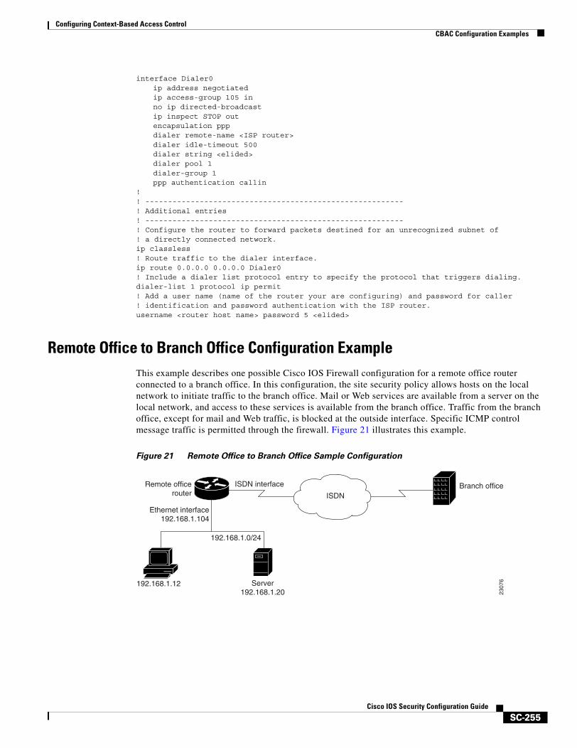
Configuring Context-Based Access ControlCBAC Configuration Examples
SC-255Cisco IOS Security Configuration Guide
interface Dialer0ip address negotiatedip access-group 105 inno ip directed-broadcastip inspect STOP outencapsulation pppdialer remote-name <ISP router>dialer idle-timeout 500dialer string <elided>dialer pool 1dialer-group 1ppp authentication callin
! ! ---------------------------------------------------------! Additional entries ! ---------------------------------------------------------! Configure the router to forward packets destined for an unrecognized subnet of! a directly connected network.ip classless! Route traffic to the dialer interface.ip route 0.0.0.0 0.0.0.0 Dialer0! Include a dialer list protocol entry to specify the protocol that triggers dialing.dialer-list 1 protocol ip permit! Add a user name (name of the router your are configuring) and password for caller! identification and password authentication with the ISP router.username <router host name> password 5 <elided>
Remote Office to Branch Office Configuration ExampleThis example describes one possible Cisco IOS Firewall configuration for a remote office router connected to a branch office. In this configuration, the site security policy allows hosts on the local network to initiate traffic to the branch office. Mail or Web services are available from a server on the local network, and access to these services is available from the branch office. Traffic from the branch office, except for mail and Web traffic, is blocked at the outside interface. Specific ICMP control message traffic is permitted through the firewall. Figure 21 illustrates this example.
Figure 21 Remote Office to Branch Office Sample Configuration
Remote officerouter
Ethernet interface192.168.1.104
192.168.1.0/24
192.168.1.12 Server192.168.1.20
Branch officeISDN
ISDN interface
2307
6

Configuring Context-Based Access ControlCBAC Configuration Examples
SC-256Cisco IOS Security Configuration Guide
The firewall has two interfaces:
• An Ethernet interface connects to the internal protected network.
Interface Ethernet0 has no ACL applied to it, meaning that all traffic initiated from the LAN is allowed access through the firewall.
• An ISDN Basic Rate Interface (BRI) connects the router to the branch office. In this example, a dialer profile is used to control the BRI interface. This means that the ACL and CBAC inspection rules are applied at dialer interface, not directly at the physical ISDN (BRI) interface.
! -------------------------------------------! General firewall configuration guidelines! -------------------------------------------! The following global configuration entries illustrate good security practices. enable secret 5 <elided>no ip source-routeno cdp run! ! ---------------------------! Create the Inspection Rule! ---------------------------! Create the CBAC inspection rule STOP to allow inspection of the specified protocol! traffic. Create the inspection rule GO to allow inspection of SMTP traffic. ip inspect name STOP tcpip inspect name STOP ftpip inspect name STOP smtpip inspect name STOP h323ip inspect name GO smtp! ! --------------------------------------------------------------! Create Access Control Lists 106 and 51! --------------------------------------------------------------! ACL 106 permits mail and Web traffic from any host to the specified server. ACL 106! denies all other ip protocol traffic except for specific ICMP control traffic. ! This means that only the return traffic for protocols defined in the ! inspection rule and the specified ICMP traffic is allowed access through the ! interface where this rule is applied.! ! Deny broadcast messages with a source address of 255.255.255.255; this helps to ! prevent broadcast attacks.access-list 106 deny ip host 255.255.255.255 any! ! Add anti-spoofing protection by denying traffic with a source address matching a host! on the Ethernet interface.access-list 106 deny ip 192.168.1.0 0.0.0.255 any ! ! ICMP traffic is not inspected by CBAC. To control the type of ICMP traffic at the! interface, add static access list entries. This example has the following ICMP! requirements: outgoing ping commands require echo-reply messages to come back,! outgoing traceroute commands require time-exceeded messages to come back, path MTU! discovery requires “too-big” messages to come back, and incoming traceroute must be! allowed. Additionally, permit all “unreachable” messages to come back; that is, if a! router cannot forward or deliver a datagram, it sends an ICMP unreachable message ! back to the source and drops the datagram.access-list 106 permit icmp any any echo-replyaccess-list 106 permit icmp any 192.168.1.0 0.0.0.255 time-exceededaccess-list 106 permit icmp any 192.168.1.0 0.0.0.255 packet-too-bigaccess-list 106 permit icmp any 192.168.1.0 0.0.0.255 tracerouteaccess-list 106 permit icmp any 192.168.1.0 0.0.0.255 unreachable! ! Permit mail and Web access to a specific server.access-list 106 permit tcp any host 192.168.1.20 eq smtpaccess-list 106 permit tcp any host 192.168.1.20 eq www!
Configuring Context-Based Access ControlCBAC Configuration Examples
SC-257Cisco IOS Security Configuration Guide
! Final deny for explicitness. This entry is not required but helps complete the access! list picture. By default, the final entry in any access list is an implicit deny of ! IP protocol traffic. This ensures that the firewall blocks any traffic not explicitly! permitted by the access list.access-list 106 deny ip any any! ! ----------------------------------------------------------! Configure the interface.! ----------------------------------------------------------! In this example, no ACLs or inspection rules are applied at interface Ethernet0, ! meaning that all traffic on the local network is allowed to go out. This assumes a! high-level of trust for the users on the local network.interface Ethernet0
ip address 192.168.1.104 255.255.255.0no ip directed-broadcast
! ! This example uses a dialer profile, so the ACL and CBAC inspection rules are applied! at the dialer interface, not the physical BRI interface. The dialer pool-member! command is used to associate the physical interface with a dialer profile. interface BRI0
no ip addressno ip directed-broadcastencapsulation pppdialer pool-member 1isdn switch-type basic-5ess
! ! ------------------------------------------------------------------! Apply the ACL and CBAC inspection rules at the dialer interface.! ------------------------------------------------------------------! Through the dialer profile, the ACL and CBAC inspection rules are ! applied to every pool member. In this example, the ACL is applied in, meaning that it ! applies to traffic inbound from the branch office. The CBAC inspection rule STOP is! applied out, meaning that CBAC monitors the traffic and controls return traffic to ! the router for an existing connection. The CBAC inspection rule GO is applied in,! protecting against certain types of DoS attacks as described in this document. Note! that the GO inspection rule does not control return traffic because there is no ACL! blocking traffic in that direction; however, it does monitor the connections.interface Dialer0
ip address <ISDN interface address>ip access-group 106 inno ip directed-broadcastip inspect STOP outip inspect GO inencapsulation pppdialer remote-name <branch office router>dialer idle-timeout 500dialer string <elided>dialer pool 1dialer-group 1ppp authentication
! ! ---------------------------------------------------------! Additional entries ! ---------------------------------------------------------! Configure the router to forward packets destined for an unrecognized subnet of! a directly connected network.ip classless! Route traffic to the dialer interface.ip route 0.0.0.0 0.0.0.0 Dialer0! Include a dialer list protocol entry to specify the protocol that triggers dialing.dialer-list 1 protocol ip permit! Add a user name (name of the router your are configuring) and password for caller! identification and password authentication with the ISP router.username <router host name> password 5 <elided>
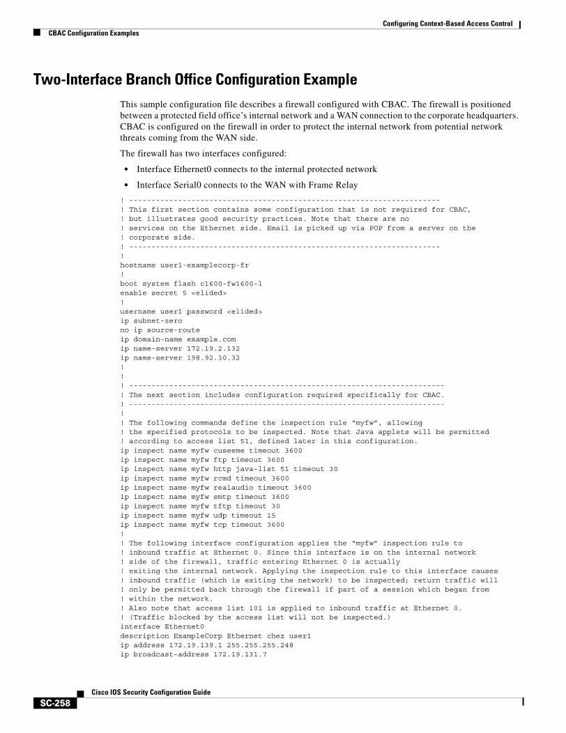
Configuring Context-Based Access ControlCBAC Configuration Examples
SC-258Cisco IOS Security Configuration Guide
Two-Interface Branch Office Configuration ExampleThis sample configuration file describes a firewall configured with CBAC. The firewall is positioned between a protected field office’s internal network and a WAN connection to the corporate headquarters. CBAC is configured on the firewall in order to protect the internal network from potential network threats coming from the WAN side.
The firewall has two interfaces configured:
• Interface Ethernet0 connects to the internal protected network
• Interface Serial0 connects to the WAN with Frame Relay
! ----------------------------------------------------------------------! This first section contains some configuration that is not required for CBAC,! but illustrates good security practices. Note that there are no ! services on the Ethernet side. Email is picked up via POP from a server on the! corporate side.! ----------------------------------------------------------------------! hostname user1-examplecorp-fr! boot system flash c1600-fw1600-lenable secret 5 <elided>! username user1 password <elided>ip subnet-zerono ip source-routeip domain-name example.comip name-server 172.19.2.132ip name-server 198.92.30.32! ! ! -----------------------------------------------------------------------! The next section includes configuration required specifically for CBAC.! -----------------------------------------------------------------------! ! The following commands define the inspection rule “myfw”, allowing! the specified protocols to be inspected. Note that Java applets will be permitted! according to access list 51, defined later in this configuration.ip inspect name myfw cuseeme timeout 3600ip inspect name myfw ftp timeout 3600ip inspect name myfw http java-list 51 timeout 30ip inspect name myfw rcmd timeout 3600ip inspect name myfw realaudio timeout 3600ip inspect name myfw smtp timeout 3600ip inspect name myfw tftp timeout 30ip inspect name myfw udp timeout 15ip inspect name myfw tcp timeout 3600! ! The following interface configuration applies the “myfw” inspection rule to! inbound traffic at Ethernet 0. Since this interface is on the internal network ! side of the firewall, traffic entering Ethernet 0 is actually ! exiting the internal network. Applying the inspection rule to this interface causes! inbound traffic (which is exiting the network) to be inspected; return traffic will! only be permitted back through the firewall if part of a session which began from! within the network.! Also note that access list 101 is applied to inbound traffic at Ethernet 0.! (Traffic blocked by the access list will not be inspected.)interface Ethernet0description ExampleCorp Ethernet chez user1ip address 172.19.139.1 255.255.255.248ip broadcast-address 172.19.131.7
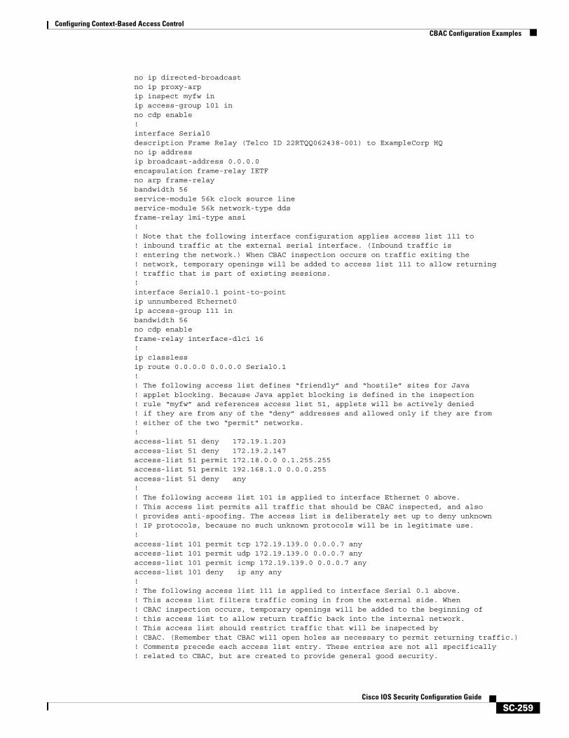
Configuring Context-Based Access ControlCBAC Configuration Examples
SC-259Cisco IOS Security Configuration Guide
no ip directed-broadcastno ip proxy-arpip inspect myfw inip access-group 101 inno cdp enable! interface Serial0description Frame Relay (Telco ID 22RTQQ062438-001) to ExampleCorp HQno ip addressip broadcast-address 0.0.0.0encapsulation frame-relay IETFno arp frame-relaybandwidth 56service-module 56k clock source lineservice-module 56k network-type ddsframe-relay lmi-type ansi! ! Note that the following interface configuration applies access list 111 to! inbound traffic at the external serial interface. (Inbound traffic is! entering the network.) When CBAC inspection occurs on traffic exiting the ! network, temporary openings will be added to access list 111 to allow returning! traffic that is part of existing sessions.! interface Serial0.1 point-to-pointip unnumbered Ethernet0ip access-group 111 inbandwidth 56no cdp enableframe-relay interface-dlci 16 ! ip classlessip route 0.0.0.0 0.0.0.0 Serial0.1! ! The following access list defines “friendly” and “hostile” sites for Java ! applet blocking. Because Java applet blocking is defined in the inspection ! rule “myfw” and references access list 51, applets will be actively denied! if they are from any of the “deny” addresses and allowed only if they are from ! either of the two “permit” networks.! access-list 51 deny 172.19.1.203access-list 51 deny 172.19.2.147access-list 51 permit 172.18.0.0 0.1.255.255access-list 51 permit 192.168.1.0 0.0.0.255access-list 51 deny any! ! The following access list 101 is applied to interface Ethernet 0 above.! This access list permits all traffic that should be CBAC inspected, and also ! provides anti-spoofing. The access list is deliberately set up to deny unknown! IP protocols, because no such unknown protocols will be in legitimate use.! access-list 101 permit tcp 172.19.139.0 0.0.0.7 anyaccess-list 101 permit udp 172.19.139.0 0.0.0.7 anyaccess-list 101 permit icmp 172.19.139.0 0.0.0.7 anyaccess-list 101 deny ip any any! ! The following access list 111 is applied to interface Serial 0.1 above.! This access list filters traffic coming in from the external side. When! CBAC inspection occurs, temporary openings will be added to the beginning of! this access list to allow return traffic back into the internal network.! This access list should restrict traffic that will be inspected by! CBAC. (Remember that CBAC will open holes as necessary to permit returning traffic.)! Comments precede each access list entry. These entries are not all specifically! related to CBAC, but are created to provide general good security.
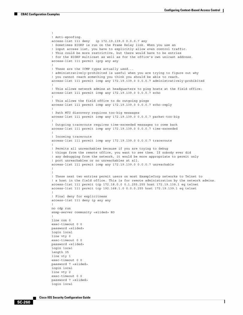
Configuring Context-Based Access ControlCBAC Configuration Examples
SC-260Cisco IOS Security Configuration Guide
! ! Anti-spoofing.access-list 111 deny ip 172.19.139.0 0.0.0.7 any! Sometimes EIGRP is run on the Frame Relay link. When you use an! input access list, you have to explicitly allow even control traffic.! This could be more restrictive, but there would have to be entries! for the EIGRP multicast as well as for the office’s own unicast address.access-list 111 permit igrp any any! ! These are the ICMP types actually used...! administratively-prohibited is useful when you are trying to figure out why! you cannot reach something you think you should be able to reach.access-list 111 permit icmp any 172.19.139.0 0.0.0.7 administratively-prohibited! ! This allows network admins at headquarters to ping hosts at the field office:access-list 111 permit icmp any 172.19.139.0 0.0.0.7 echo! ! This allows the field office to do outgoing pingsaccess-list 111 permit icmp any 172.19.139.0 0.0.0.7 echo-reply! ! Path MTU discovery requires too-big messagesaccess-list 111 permit icmp any 172.19.139.0 0.0.0.7 packet-too-big! ! Outgoing traceroute requires time-exceeded messages to come backaccess-list 111 permit icmp any 172.19.139.0 0.0.0.7 time-exceeded! ! Incoming tracerouteaccess-list 111 permit icmp any 172.19.139.0 0.0.0.7 traceroute! ! Permits all unreachables because if you are trying to debug! things from the remote office, you want to see them. If nobody ever did ! any debugging from the network, it would be more appropriate to permit only ! port unreachables or no unreachables at all.access-list 111 permit icmp any 172.19.139.0 0.0.0.7 unreachable! ! ! These next two entries permit users on most ExampleCorp networks to Telnet to! a host in the field office. This is for remote administration by the network admins.access-list 111 permit tcp 172.18.0.0 0.1.255.255 host 172.19.139.1 eq telnetaccess-list 111 permit tcp 192.168.1.0 0.0.0.255 host 172.19.139.1 eq telnet! ! Final deny for explicitnessaccess-list 111 deny ip any any! no cdp runsnmp-server community <elided> RO! line con 0exec-timeout 0 0password <elided>login localline vty 0exec-timeout 0 0password <elided>login locallength 35line vty 1exec-timeout 0 0password 7 <elided>login localline vty 2exec-timeout 0 0password 7 <elided>login local
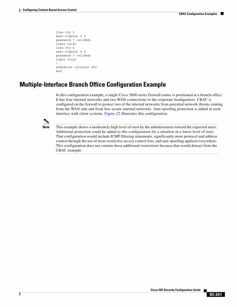
Configuring Context-Based Access ControlCBAC Configuration Examples
SC-261Cisco IOS Security Configuration Guide
line vty 3exec-timeout 0 0password 7 <elided>login localline vty 4exec-timeout 0 0password 7 <elided>login local! scheduler interval 500end
Multiple-Interface Branch Office Configuration ExampleIn this configuration example, a single Cisco 3600 series firewall router is positioned at a branch office. It has four internal networks and two WAN connections to the corporate headquarters. CBAC is configured on the firewall to protect two of the internal networks from potential network threats coming from the WAN side and from less secure internal networks. Anti-spoofing protection is added at each interface with client systems. Figure 22 illustrates this configuration.
Note This example shows a moderately high level of trust by the administrators toward the expected users. Additional protection could be added to this configuration for a situation in a lower level of trust. That configuration would include ICMP filtering statements, significantly more protocol and address control through the use of more restrictive access control lists, and anti-spoofing applied everywhere. This configuration does not contain those additional restrictions because that would detract from the CBAC example.

Configuring Context-Based Access ControlCBAC Configuration Examples
SC-262Cisco IOS Security Configuration Guide
Figure 22 Sample Cisco IOS Firewall Application Environment
The branch office has this sample network configuration:
• Ethernet interface 0/0 supports the Human Resources department servers. This network includes an email (SMTP and POP3) host and a Windows NT server. The Windows NT server is the Primary Domain Controller (PDC) for the Human Resources domain and has a trust relationship with the rest of the company; however, it contains applications and databases that must not be accessed by the rest of the company or the other groups in the branch office. The devices on this LAN are accessible only by users in the Human Resources department on Ethernet interface 0/1. The Mail server must be able to send and receive email (through SMTP sessions) with all other devices. The Windows 95 machines can use this machine as their email server (for sending email through SMTP sessions) and as a repository for accumulating email that they can then download through POP3 sessions. No one else in the company is allowed to form POP3 sessions to any machine on this LAN.
• Ethernet interface 0/1 supports the Windows 95 computers in the Human Resources department. These users must have access to the Human Resources mail servers located on Ethernet interface 0/0 as well as access to the rest of the company. Access to the Windows NT server resources are controlled through the Windows NT permissions assigned to each user in the Windows NT domain.
Human resourcesserver network
Human resourcesdepartment PCs
Branch office PCs
Branch officeweb servers
and BDC
172.16.140.0Ethernet 1/1
172.16.130.0Ethernet 1/0
172.16.120.0Ethernet 0/1
Ethernet 0/0172.16.110.0
Serial 0/0192.168.150.0
Serial 0/1192.168.160.0
Branch office
Cisco 3600series router
1576
4
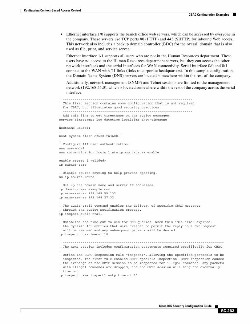
Configuring Context-Based Access ControlCBAC Configuration Examples
SC-263Cisco IOS Security Configuration Guide
• Ethernet interface 1/0 supports the branch office web servers, which can be accessed by everyone in the company. These servers use TCP ports 80 (HTTP) and 443 (SHTTP) for inbound Web access. This network also includes a backup domain controller (BDC) for the overall domain that is also used as file, print, and service server.
Ethernet interface 1/1 supports all users who are not in the Human Resources department. These users have no access to the Human Resources department servers, but they can access the other network interfaces and the serial interfaces for WAN connectivity. Serial interface 0/0 and 0/1 connect to the WAN with T1 links (links to corporate headquarters). In this sample configuration, the Domain Name System (DNS) servers are located somewhere within the rest of the company.
Additionally, network management (SNMP) and Telnet sessions are limited to the management network (192.168.55.0), which is located somewhere within the rest of the company across the serial interface.
! ------------------------------------------------------------------! This first section contains some configuration that is not required! for CBAC, but illustrates good security practices.! ------------------------------------------------------------------! Add this line to get timestamps on the syslog messages.service timestamps log datetime localtime show-timezone! hostname Router1! boot system flash c3600-fw3600-l! ! Configure AAA user authentication.aaa new-modelaaa authentication login lista group tacacs+ enable! enable secret 5 <elided>ip subnet-zero! ! Disable source routing to help prevent spoofing.no ip source-route! ! Set up the domain name and server IP addresses.ip domain-name example.comip name-server 192.168.55.132ip name-server 192.168.27.32! ! The audit-trail command enables the delivery of specific CBAC messages ! through the syslog notification process.ip inspect audit-trail ! ! Establish the time-out values for DNS queries. When this idle-timer expires,! the dynamic ACL entries that were created to permit the reply to a DNS request ! will be removed and any subsequent packets will be denied.ip inspect dns-timeout 10!! ----------------------------------------------------------------------------------! The next section includes configuration statements required specifically for CBAC.! ----------------------------------------------------------------------------------! Define the CBAC inspection rule “inspect1”, allowing the specified protocols to be! inspected. The first rule enables SMTP specific inspection. SMTP inspection causes! the exchange of the SMTP session to be inspected for illegal commands. Any packets! with illegal commands are dropped, and the SMTP session will hang and eventually! time out.ip inspect name inspect1 smtp timeout 30
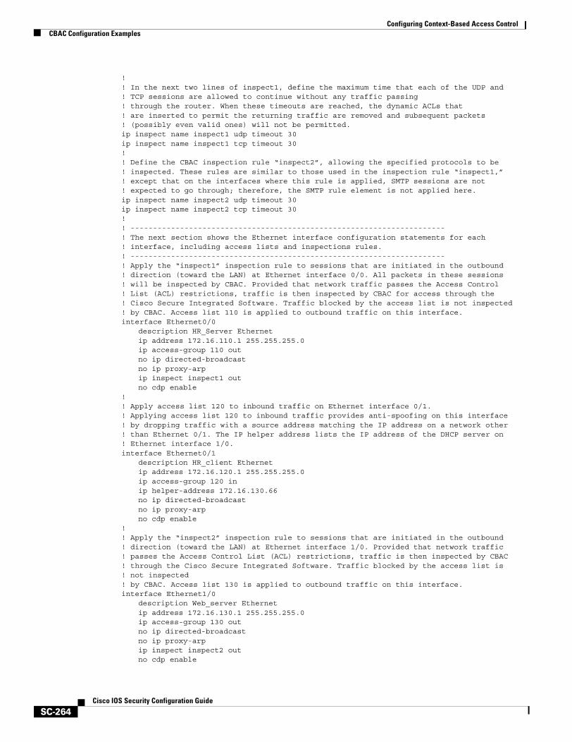
Configuring Context-Based Access ControlCBAC Configuration Examples
SC-264Cisco IOS Security Configuration Guide
!! In the next two lines of inspect1, define the maximum time that each of the UDP and ! TCP sessions are allowed to continue without any traffic passing ! through the router. When these timeouts are reached, the dynamic ACLs that ! are inserted to permit the returning traffic are removed and subsequent packets! (possibly even valid ones) will not be permitted.ip inspect name inspect1 udp timeout 30ip inspect name inspect1 tcp timeout 30!! Define the CBAC inspection rule “inspect2”, allowing the specified protocols to be! inspected. These rules are similar to those used in the inspection rule “inspect1,”! except that on the interfaces where this rule is applied, SMTP sessions are not ! expected to go through; therefore, the SMTP rule element is not applied here.ip inspect name inspect2 udp timeout 30ip inspect name inspect2 tcp timeout 30!! ----------------------------------------------------------------------! The next section shows the Ethernet interface configuration statements for each ! interface, including access lists and inspections rules. ! ----------------------------------------------------------------------! Apply the “inspect1” inspection rule to sessions that are initiated in the outbound ! direction (toward the LAN) at Ethernet interface 0/0. All packets in these sessions! will be inspected by CBAC. Provided that network traffic passes the Access Control! List (ACL) restrictions, traffic is then inspected by CBAC for access through the! Cisco Secure Integrated Software. Traffic blocked by the access list is not inspected! by CBAC. Access list 110 is applied to outbound traffic on this interface. interface Ethernet0/0
description HR_Server Ethernetip address 172.16.110.1 255.255.255.0ip access-group 110 outno ip directed-broadcastno ip proxy-arpip inspect inspect1 outno cdp enable
!! Apply access list 120 to inbound traffic on Ethernet interface 0/1.! Applying access list 120 to inbound traffic provides anti-spoofing on this interface! by dropping traffic with a source address matching the IP address on a network other! than Ethernet 0/1. The IP helper address lists the IP address of the DHCP server on! Ethernet interface 1/0. interface Ethernet0/1
description HR_client Ethernetip address 172.16.120.1 255.255.255.0ip access-group 120 inip helper-address 172.16.130.66no ip directed-broadcastno ip proxy-arpno cdp enable
!! Apply the “inspect2” inspection rule to sessions that are initiated in the outbound! direction (toward the LAN) at Ethernet interface 1/0. Provided that network traffic! passes the Access Control List (ACL) restrictions, traffic is then inspected by CBAC! through the Cisco Secure Integrated Software. Traffic blocked by the access list is! not inspected! by CBAC. Access list 130 is applied to outbound traffic on this interface. interface Ethernet1/0
description Web_server Ethernetip address 172.16.130.1 255.255.255.0ip access-group 130 outno ip directed-broadcastno ip proxy-arpip inspect inspect2 outno cdp enable
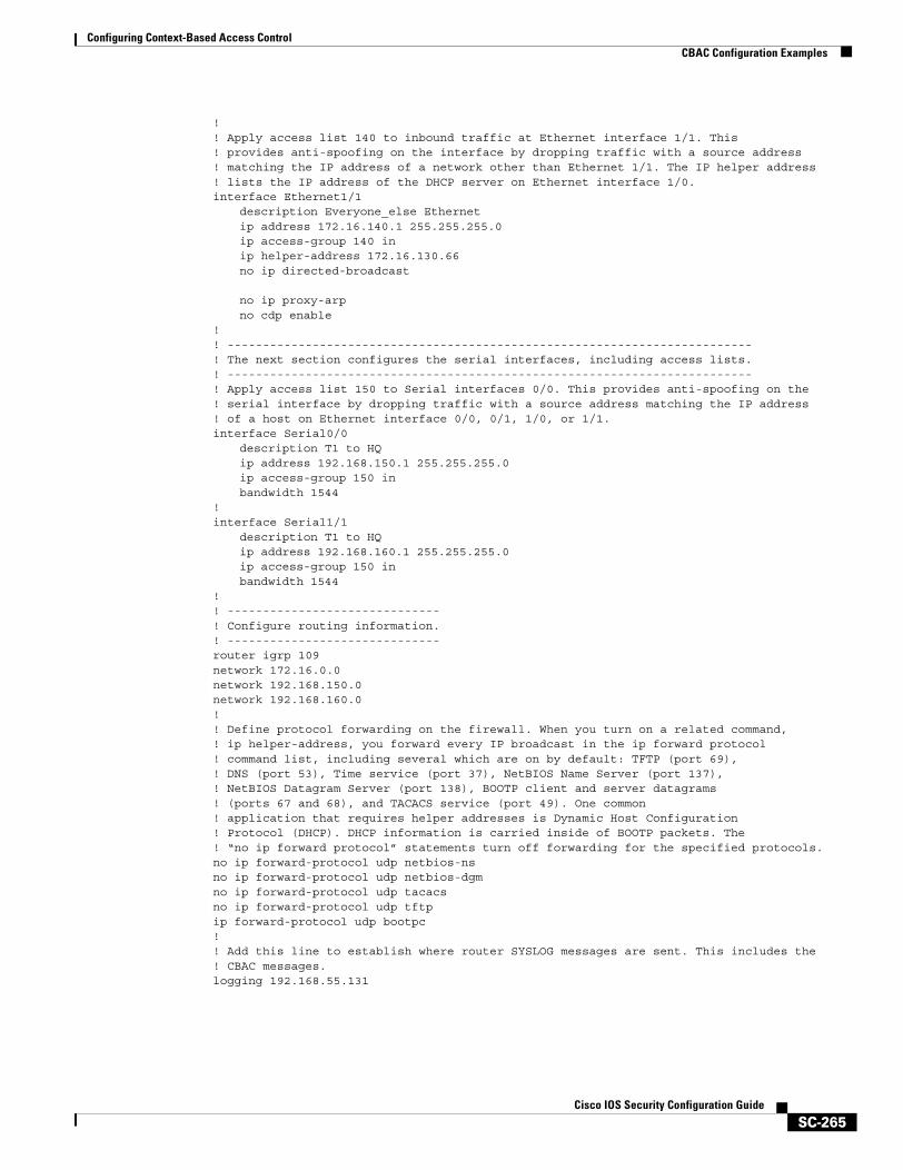
Configuring Context-Based Access ControlCBAC Configuration Examples
SC-265Cisco IOS Security Configuration Guide
!! Apply access list 140 to inbound traffic at Ethernet interface 1/1. This! provides anti-spoofing on the interface by dropping traffic with a source address! matching the IP address of a network other than Ethernet 1/1. The IP helper address! lists the IP address of the DHCP server on Ethernet interface 1/0. interface Ethernet1/1
description Everyone_else Ethernetip address 172.16.140.1 255.255.255.0ip access-group 140 inip helper-address 172.16.130.66no ip directed-broadcast
no ip proxy-arpno cdp enable
!! --------------------------------------------------------------------------! The next section configures the serial interfaces, including access lists.! --------------------------------------------------------------------------! Apply access list 150 to Serial interfaces 0/0. This provides anti-spoofing on the! serial interface by dropping traffic with a source address matching the IP address! of a host on Ethernet interface 0/0, 0/1, 1/0, or 1/1.interface Serial0/0
description T1 to HQip address 192.168.150.1 255.255.255.0ip access-group 150 inbandwidth 1544
!interface Serial1/1
description T1 to HQip address 192.168.160.1 255.255.255.0ip access-group 150 inbandwidth 1544
!! ------------------------------! Configure routing information.! ------------------------------router igrp 109network 172.16.0.0network 192.168.150.0network 192.168.160.0!! Define protocol forwarding on the firewall. When you turn on a related command, ! ip helper-address, you forward every IP broadcast in the ip forward protocol! command list, including several which are on by default: TFTP (port 69), ! DNS (port 53), Time service (port 37), NetBIOS Name Server (port 137), ! NetBIOS Datagram Server (port 138), BOOTP client and server datagrams ! (ports 67 and 68), and TACACS service (port 49). One common! application that requires helper addresses is Dynamic Host Configuration! Protocol (DHCP). DHCP information is carried inside of BOOTP packets. The! “no ip forward protocol” statements turn off forwarding for the specified protocols.no ip forward-protocol udp netbios-nsno ip forward-protocol udp netbios-dgmno ip forward-protocol udp tacacs no ip forward-protocol udp tftp ip forward-protocol udp bootpc!! Add this line to establish where router SYSLOG messages are sent. This includes the! CBAC messages. logging 192.168.55.131
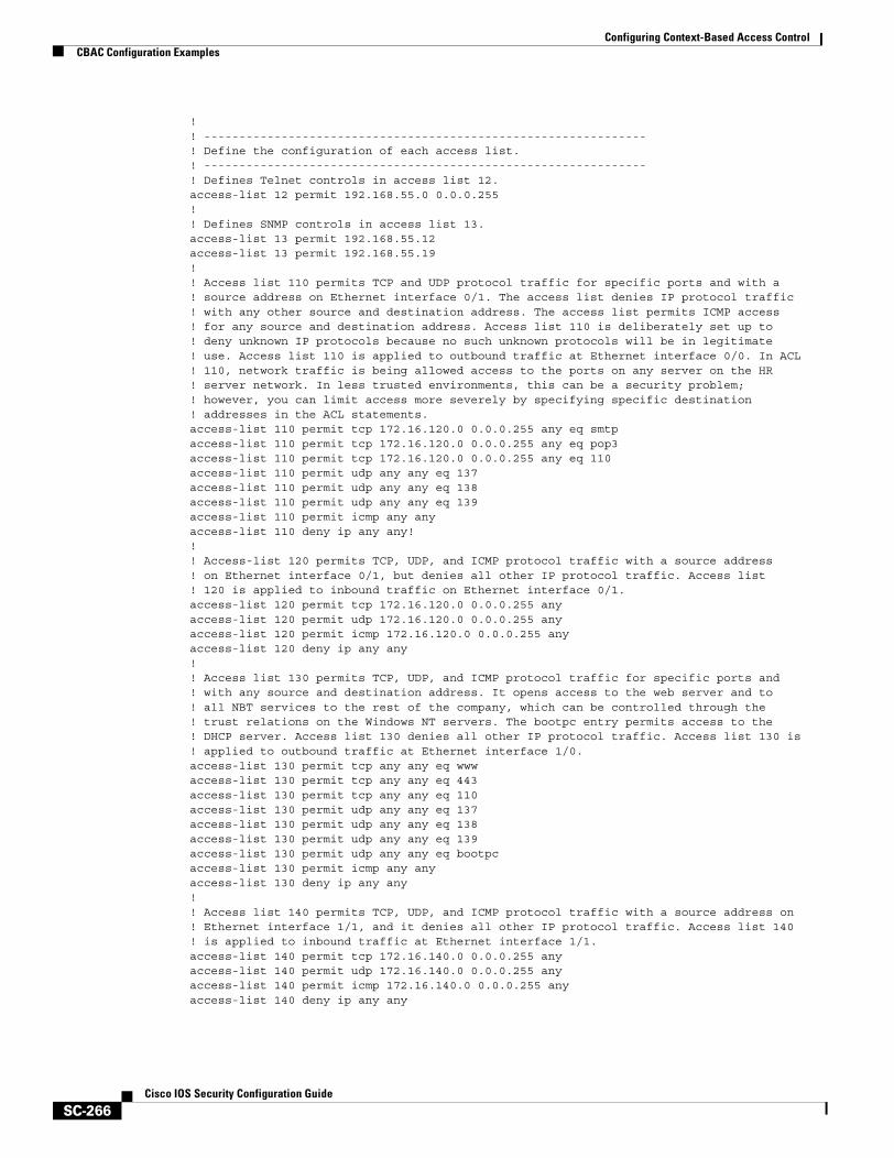
Configuring Context-Based Access ControlCBAC Configuration Examples
SC-266Cisco IOS Security Configuration Guide
!! ---------------------------------------------------------------! Define the configuration of each access list. ! ---------------------------------------------------------------! Defines Telnet controls in access list 12.access-list 12 permit 192.168.55.0 0.0.0.255!! Defines SNMP controls in access list 13. access-list 13 permit 192.168.55.12access-list 13 permit 192.168.55.19!! Access list 110 permits TCP and UDP protocol traffic for specific ports and with a ! source address on Ethernet interface 0/1. The access list denies IP protocol traffic ! with any other source and destination address. The access list permits ICMP access ! for any source and destination address. Access list 110 is deliberately set up to ! deny unknown IP protocols because no such unknown protocols will be in legitimate ! use. Access list 110 is applied to outbound traffic at Ethernet interface 0/0. In ACL ! 110, network traffic is being allowed access to the ports on any server on the HR ! server network. In less trusted environments, this can be a security problem; ! however, you can limit access more severely by specifying specific destination ! addresses in the ACL statements.access-list 110 permit tcp 172.16.120.0 0.0.0.255 any eq smtpaccess-list 110 permit tcp 172.16.120.0 0.0.0.255 any eq pop3access-list 110 permit tcp 172.16.120.0 0.0.0.255 any eq 110access-list 110 permit udp any any eq 137access-list 110 permit udp any any eq 138access-list 110 permit udp any any eq 139access-list 110 permit icmp any any access-list 110 deny ip any any!!! Access-list 120 permits TCP, UDP, and ICMP protocol traffic with a source address ! on Ethernet interface 0/1, but denies all other IP protocol traffic. Access list! 120 is applied to inbound traffic on Ethernet interface 0/1.access-list 120 permit tcp 172.16.120.0 0.0.0.255 anyaccess-list 120 permit udp 172.16.120.0 0.0.0.255 anyaccess-list 120 permit icmp 172.16.120.0 0.0.0.255 anyaccess-list 120 deny ip any any!! Access list 130 permits TCP, UDP, and ICMP protocol traffic for specific ports and! with any source and destination address. It opens access to the web server and to! all NBT services to the rest of the company, which can be controlled through the! trust relations on the Windows NT servers. The bootpc entry permits access to the! DHCP server. Access list 130 denies all other IP protocol traffic. Access list 130 is! applied to outbound traffic at Ethernet interface 1/0.access-list 130 permit tcp any any eq wwwaccess-list 130 permit tcp any any eq 443access-list 130 permit tcp any any eq 110access-list 130 permit udp any any eq 137access-list 130 permit udp any any eq 138access-list 130 permit udp any any eq 139access-list 130 permit udp any any eq bootpc access-list 130 permit icmp any any access-list 130 deny ip any any!! Access list 140 permits TCP, UDP, and ICMP protocol traffic with a source address on! Ethernet interface 1/1, and it denies all other IP protocol traffic. Access list 140! is applied to inbound traffic at Ethernet interface 1/1.access-list 140 permit tcp 172.16.140.0 0.0.0.255 anyaccess-list 140 permit udp 172.16.140.0 0.0.0.255 anyaccess-list 140 permit icmp 172.16.140.0 0.0.0.255 anyaccess-list 140 deny ip any any

Configuring Context-Based Access ControlCBAC Configuration Examples
SC-267Cisco IOS Security Configuration Guide
!! Access list 150 denies IP protocol traffic with a source address on Ethernet ! interfaces 0/0, 0/1, 1/0, and 1/1, and it permits IP protocol traffic with any other! source and destination address. Access list 150 is applied to inbound traffic! on each of the serial interfaces.access-list 150 deny ip 172.16.110.0 0.0.0.255 anyaccess-list 150 deny ip 172.16.120.0 0.0.0.255 anyaccess-list 150 deny ip 172.16.130.0 0.0.0.255 anyaccess-list 150 deny ip 172.16.140.0 0.0.0.255 anyaccess-list 150 permit ip any any!! Disable Cisco Discovery Protocol.no cdp run !snmp-server community <elided> ro 13tacacs-server host 192.168.55.2tacacs-server key <elided>!! -----------------------------------------------------------------------------------! Configures the router console port and the virtual terminal line interfaces,! including AAA authentication at login. Authentication is required for users defined! in “lista.” Access-class 12 is applied on each line, restricting Telnet access to! connections with a source address on the network management network.! -----------------------------------------------------------------------------------line console 0exec-timeout 3 00login authentication listaline aux 0exec-timeout 3 00login authentication listaline vty 0
exec-timeout 1 30login authentication listaaccess-class 12 in
line vty 1exec-timeout 1 30login authentication listaaccess-class 12 in
line vty 2exec-timeout 1 30login authentication listaaccess-class 12 in
line vty 3exec-timeout 1 30login authentication listaaccess-class 12 in
line vty 4exec-timeout 1 30login authentication listaaccess-class 12 in
!end

Configuring Context-Based Access ControlCBAC Configuration Examples
SC-268Cisco IOS Security Configuration Guide
SC-269Cisco IOS Security Configuration Guide
Configuring Cisco IOS Firewall Intrusion Detection System
This chapter describes the Cisco IOS Firewall Intrusion Detection System (IDS) feature. Intrusion detection systems provide a level of protection beyond the firewall by protecting the network from internal and external attacks and threats. Cisco IOS Firewall IDS technology enhances perimeter firewall protection by taking appropriate action on packets and flows that violate the security policy or represent malicious network activity.
For a complete description of the Cisco IOS Firewall IDS commands in this chapter, refer to the “Cisco IOS Firewall IDS Commands” chapter of the Cisco IOS Security Command Reference. To locate documentation of other commands that appear in this chapter, use the command reference master index or search online.
To identify the hardware platform or software image information associated with a feature, use the Feature Navigator on Cisco.com to search for information about the feature or refer to the software release notes for a specific release. For more information, see the chapter “Identifying Supported Platforms” section in the “Using Cisco IOS Software.”
In This ChapterThis chapter has the following sections:
• About the Firewall Intrusion Detection System
• Cisco IOS Firewall IDS Configuration Task List
• Monitoring and Maintaining Cisco IOS Firewall IDS
• Cisco IOS Firewall IDS Configuration Examples
About the Firewall Intrusion Detection SystemThe Cisco IOS Firewall IDS feature supports intrusion detection technology for midrange and high-end router platforms with firewall support. It is ideal for any network perimeter, and especially for locations in which a router is being deployed and additional security between network segments is required. It also can protect intranet and extranet connections where additional security is mandated, and branch-office sites connecting to the corporate office or Internet.
Configuring Cisco IOS Firewall Intrusion Detection SystemAbout the Firewall Intrusion Detection System
SC-270Cisco IOS Security Configuration Guide
The Cisco IOS Firewall IDS feature identifies 59 of the most common attacks using “signatures” to detect patterns of misuse in network traffic. The intrusion-detection signatures included in the Cisco IOS Firewall were chosen from a broad cross-section of intrusion-detection signatures. The signatures represent severe breaches of security and the most common network attacks and information-gathering scans. For a description of Cisco IOS Firewall IDS signatures, refer to the “Cisco IOS Firewall IDS Signature List” section.
The Cisco IOS Firewall IDS acts as an in-line intrusion detection sensor, watching packets and sessions as they flow through the router, scanning each to match any of the IDS signatures. When it detects suspicious activity, it responds before network security can be compromised and logs the event through Cisco IOS syslog or the Cisco Secure Intrusion Detection System (Cisco Secure IDS, formerly known as NetRanger) Post Office Protocol. The network administrator can configure the IDS system to choose the appropriate response to various threats. When packets in a session match a signature, the IDS system can be configured to take these actions:
• Send an alarm to a syslog server or a Cisco Secure IDS Director (centralized management interface)
• Drop the packet
• Reset the TCP connection
Cisco developed its Cisco IOS software-based intrusion-detection capabilities in Cisco IOS Firewall with flexibility in mind, so that individual signatures could be disabled in case of false positives. Also, while it is preferable to enable both the firewall and intrusion detection features of the CBAC security engine to support a network security policy, each of these features may be enabled independently and on different router interfaces. Cisco IOS software-based intrusion detection is part of the Cisco IOS Firewall.
This section has the following sections:
• Compatibility with Cisco Secure Intrusion Detection
• Functional Description
• When to Use Cisco IOS Firewall IDS
• Memory and Performance Impact
• Cisco IOS Firewall IDS Signature List
Compatibility with Cisco Secure Intrusion DetectionCisco IOS Firewall is compatible with the Cisco Secure Intrusion Detection System (formally known as NetRanger). The Cisco Secure IDS is an enterprise-scale, real-time, intrusion detection system designed to detect, report, and terminate unauthorized activity throughout a network.
The Cisco Secure IDS consists of three components:
• Sensor
• Director
• Post Office
Cisco Secure IDS Sensors, which are high-speed network appliances, analyze the content and context of individual packets to determine if traffic is authorized. If a network's data stream exhibits unauthorized or suspicious activity, such as a SATAN attack, a ping sweep, or the transmission of a secret research project code word, Cisco Secure IDS Sensors can detect the policy violation in real time, forward alarms to a Cisco Secure IDS Director management console, and remove the offender from the network.
The Cisco Secure IDS Director is a high-performance, software-based management system that centrally monitors the activity of multiple Cisco Secure IDS Sensors located on local or remote network segments.
Configuring Cisco IOS Firewall Intrusion Detection SystemAbout the Firewall Intrusion Detection System
SC-271Cisco IOS Security Configuration Guide
The Cisco Secure IDS Post Office is the communication backbone that allows Cisco Secure IDS services and hosts to communicate with each other. All communication is supported by a proprietary, connection-based protocol that can switch between alternate routes to maintain point-to-point connections.
Cisco Secure IDS customers can deploy the Cisco IOS Firewall IDS signatures to complement their existing IDS systems. This allows an IDS to be deployed to areas that may not be capable of supporting a Cisco Secure IDS Sensor. Cisco IOS Firewall IDS signatures can be deployed alongside or independently of other Cisco IOS Firewall features.
The Cisco IOS Firewall IDS can be added to the Cisco Secure IDS Director screen as an icon to provide a consistent view of all intrusion detection sensors throughout a network. The Cisco IOS Firewall intrusion detection capabilities have an enhanced reporting mechanism that permits logging to the Cisco Secure IDS Director console in addition to Cisco IOS syslog.
For additional information about Cisco Secure IDS (NetRanger), refer to the NetRanger User Guide.
Functional DescriptionThe Cisco IOS Firewall IDS acts as an in-line intrusion detection sensor, watching packets as they traverse the router’s interfaces and acting upon them in a definable fashion. When a packet, or a number of packets in a session, match a signature, the Cisco IOS Firewall IDS may perform the following configurable actions:
• Alarm—Sends an alarm to a syslog server or Cisco Secure IDS Director
• Drop—Drops the packet
• Reset—Resets the TCP connection
The following describes the packet auditing process with Cisco IOS Firewall IDS:
• You create an audit rule, which specifies the signatures that should be applied to packet traffic and the actions to take when a match is found. An audit rule can apply informational and attack signatures to network packets. The signature list can have just one signature, all signatures, or any number of signatures in between. Signatures can be disabled in case of false positives or the needs of the network environment.
• You apply the audit rule to an interface on the router, specifying a traffic direction (in or out).
• If the audit rule is applied to the in direction of the interface, packets passing through the interface are audited before the inbound ACL has a chance to discard them. This allows an administrator to be alerted if an attack or information-gathering activity is underway even if the router would normally reject the activity.
• If the audit rule is applied to the out direction on the interface, packets are audited after they enter the router through another interface. In this case, the inbound ACL of the other interface may discard packets before they are audited. This may result in the loss of Cisco IOS Firewall IDS alarms even though the attack or information-gathering activity was thwarted.
Configuring Cisco IOS Firewall Intrusion Detection SystemAbout the Firewall Intrusion Detection System
SC-272Cisco IOS Security Configuration Guide
• Packets going through the interface that match the audit rule are audited by a series of modules, starting with IP; then either ICMP, TCP, or UDP (as appropriate); and finally, the Application level.
• If a signature match is found in a module, then the following user-configured action(s) occur:
– If the action is alarm, then the module completes its audit, sends an alarm, and passes the packet to the next module.
– If the action is drop, then the packet is dropped from the module, discarded, and not sent to the next module.
– If the action is reset, then the packets are forwarded to the next module, and packets with the reset flag set are sent to both participants of the session, if the session is TCP.
Note It is recommended that you use the drop and reset actions together.
If there are multiple signature matches in a module, only the first match fires an action. Additional matches in other modules fire additional alarms, but only one per module.
Note This process is different than on the Cisco Secure IDS Sensor appliance, which identifies all signature matches for each packet.
When to Use Cisco IOS Firewall IDSCisco IOS Firewall IDS capabilities are ideal for providing additional visibility at intranet, extranet, and branch-office Internet perimeters. Network administrators enjoy more robust protection against attacks on the network and can automatically respond to threats from internal or external hosts.
The Cisco IOS Firewall with intrusion detection is intended to satisfy the security goals of all of our customers, and is particularly appropriate for the following scenarios:
• Enterprise customers that are interested in a cost-effective method of extending their perimeter security across all network boundaries, specifically branch-office, intranet, and extranet perimeters.
• Small and medium-sized businesses that are looking for a cost-effective router that has an integrated firewall with intrusion-detection capabilities.
• Service provider customers that want to set up managed services, providing firewalling and intrusion detection to their customers, all housed within the necessary function of a router.
Memory and Performance ImpactThe performance impact of intrusion detection will depend on the configuration of the signatures, the level of traffic on the router, the router platform, and other individual features enabled on the router such as encryption, source route bridging, and so on. Enabling or disabling individual signatures will not alter performance significantly, however, signatures that are configured to use Access Control Lists will have a significant performance impact.
Because this router is being used as a security device, no packet will be allowed to bypass the security mechanisms. The IDS process in the Cisco IOS Firewall router sits directly in the packet path and thus will search each packet for signature matches. In some cases, the entire packet will need to be searched, and state information and even application state and awareness must be maintained by the router.

Configuring Cisco IOS Firewall Intrusion Detection SystemAbout the Firewall Intrusion Detection System
SC-273Cisco IOS Security Configuration Guide
For auditing atomic signatures, there is no traffic-dependent memory requirement. For auditing compound signatures, CBAC allocates memory to maintain the state of each session for each connection. Memory is also allocated for the configuration database and for internal caching.
Cisco IOS Firewall IDS Signature ListThe following is a complete list of Cisco IOS Firewall IDS signatures. A signature detects patterns of misuse in network traffic. In Cisco IOS Firewall IDS, signatures are categorized into four types:
• Info Atomic
• Info Compound
• Attack Atomic
• Attack Compound
An info signature detects information-gathering activity, such as a port sweep.
An attack signature detects attacks attempted into the protected network, such as denial-of-service attempts or the execution of illegal commands during an FTP session.
Info and attack signatures can be either atomic or compound signatures. Atomic signatures can detect patterns as simple as an attempt to access a specific port on a specific host. Compound signatures can detect complex patterns, such as a sequence of operations distributed across multiple hosts over an arbitrary period of time.
The intrusion-detection signatures included in the Cisco IOS Firewall were chosen from a broad cross-section of intrusion-detection signatures as representative of the most common network attacks and information-gathering scans that are not commonly found in an operational network.
The following signatures are listed in numerical order by their signature number in the Cisco Secure IDS Network Security Database. After each signature’s name is an indication of the type of signature (info or attack, atomic or compound).
Note Atomic signatures marked with an asterisk (Atomic*) are allocated memory for session states by CBAC.
1000 IP options-Bad Option List (Info, Atomic)
Triggers on receipt of an IP datagram where the list of IP options in the IP datagram header is incomplete or malformed. The IP options list contains one or more options that perform various network management or debugging tasks.
1001 IP options-Record Packet Route (Info, Atomic)
Triggers on receipt of an IP datagram where the IP option list for the datagram includes option 7 (Record Packet Route).
1002 IP options-Timestamp (Info, Atomic)
Triggers on receipt of an IP datagram where the IP option list for the datagram includes option 4 (Timestamp).
1003 IP options-Provide s,c,h,tcc (Info, Atomic)
Triggers on receipt of an IP datagram where the IP option list for the datagram includes option 2 (Security options).

Configuring Cisco IOS Firewall Intrusion Detection SystemAbout the Firewall Intrusion Detection System
SC-274Cisco IOS Security Configuration Guide
1004 IP options-Loose Source Route (Info, Atomic)
Triggers on receipt of an IP datagram where the IP option list for the datagram includes option 3 (Loose Source Route).
1005 IP options-SATNET ID (Info, Atomic)
Triggers on receipt of an IP datagram where the IP option list for the datagram includes option 8 (SATNET stream identifier).
1006 IP options-Strict Source Route (Info, Atomic)
Triggers on receipt of an IP datagram in which the IP option list for the datagram includes option 2 (Strict Source Routing).
1100 IP Fragment Attack (Attack, Atomic)
Triggers when any IP datagram is received with the “more fragments” flag set to 1 or if there is an offset indicated in the offset field.
1101 Unknown IP Protocol (Attack, Atomic)
Triggers when an IP datagram is received with the protocol field set to 101 or greater. These protocol types are undefined or reserved and should not be used.
1102 Impossible IP Packet (Attack, Atomic)
This triggers when an IP packet arrives with source equal to destination address. This signature will catch the so-called Land Attack.
2000 ICMP Echo Reply (Info, Atomic)
Triggers when a IP datagram is received with the “protocol” field in the IP header set to 1 (ICMP) and the “type” field in the ICMP header set to 0 (Echo Reply).
2001 ICMP Host Unreachable (Info, Atomic)
Triggers when an IP datagram is received with the “protocol” field in the IP header set to 1 (ICMP) and the “type” field in the ICMP header set to 3 (Host Unreachable).
2002 ICMP Source Quench (Info, Atomic)
Triggers when an IP datagram is received with the “protocol” field in the IP header set to 1 (ICMP) and the “type” field in the ICMP header set to 4 (Source Quench).
2003 ICMP Redirect (Info, Atomic)
Triggers when an IP datagram is received with the “protocol” field in the IP header set to 1 (ICMP) and the “type” field in the ICMP header set to 5 (Redirect).
2004 ICMP Echo Request (Info, Atomic)
Triggers when an IP datagram is received with the “protocol” field in the IP header set to 1 (ICMP) and the “type” field in the ICMP header set to 8 (Echo Request).
2005 ICMP Time Exceeded for a Datagram (Info, Atomic)
Triggers when an IP datagram is received with the “protocol” field in the IP header set to 1 (ICMP) and the “type” field in the ICMP header set to 11(Time Exceeded for a Datagram).

Configuring Cisco IOS Firewall Intrusion Detection SystemAbout the Firewall Intrusion Detection System
SC-275Cisco IOS Security Configuration Guide
2006 ICMP Parameter Problem on Datagram (Info, Atomic)
Triggers when an IP datagram is received with the “protocol” field in the IP header set to 1 (ICMP) and the “type” field in the ICMP header set to 12 (Parameter Problem on Datagram).
2007 ICMP Timestamp Request (Info, Atomic)
Triggers when an IP datagram is received with the “protocol” field in the IP header set to 1 (ICMP) and the “type” field in the ICMP header set to 13 (Timestamp Request).
2008 ICMP Timestamp Reply (Info, Atomic)
Triggers when an IP datagram is received with the “protocol” field in the IP header set to 1 (ICMP) and the “type” field in the ICMP header set to 14 (Timestamp Reply).
2009 ICMP Information Request (Info, Atomic)
Triggers when an IP datagram is received with the “protocol” field in the IP header set to 1 (ICMP) and the “type” field in the ICMP header set to 15 (Information Request).
2010 ICMP Information Reply (Info, Atomic)
Triggers when an IP datagram is received with the “protocol” field in the IP header set to 1 (ICMP) and the “type” field in the ICMP header set to 16 (ICMP Information Reply).
2011 ICMP Address Mask Request (Info, Atomic)
Triggers when an IP datagram is received with the “protocol” field in the IP header set to 1 (ICMP) and the “type” field in the ICMP header set to 17 (Address Mask Request).
2012 ICMP Address Mask Reply (Info, Atomic)
Triggers when an IP datagram is received with the “protocol” field in the IP header set to 1 (ICMP) and the “type” field in the ICMP header set to 18 (Address Mask Reply).
2150 Fragmented ICMP Traffic (Attack, Atomic)
Triggers when an IP datagram is received with the protocol field in the IP header set to 1 (ICMP) and either the more fragments flag is set to 1 (ICMP) or there is an offset indicated in the offset field.
2151 Large ICMP Traffic (Attack, Atomic)
Triggers when an IP datagram is received with the protocol field in the IP header set to 1 (ICMP) and the IP length is greater than 1024.
2154 Ping of Death Attack (Attack, Atomic)
Triggers when an IP datagram is received with the protocol field in the IP header set to 1 (ICMP), the Last Fragment bit is set, and
( IP offset * 8 ) + (IP data length) > 65535
In other words, the IP offset (which represents the starting position of this fragment in the original packet, and which is in 8-byte units) plus the rest of the packet is greater than the maximum size for an IP packet.
3040 TCP - no bits set in flags (Attack, Atomic)
Triggers when a TCP packet is received with no bits set in the flags field.
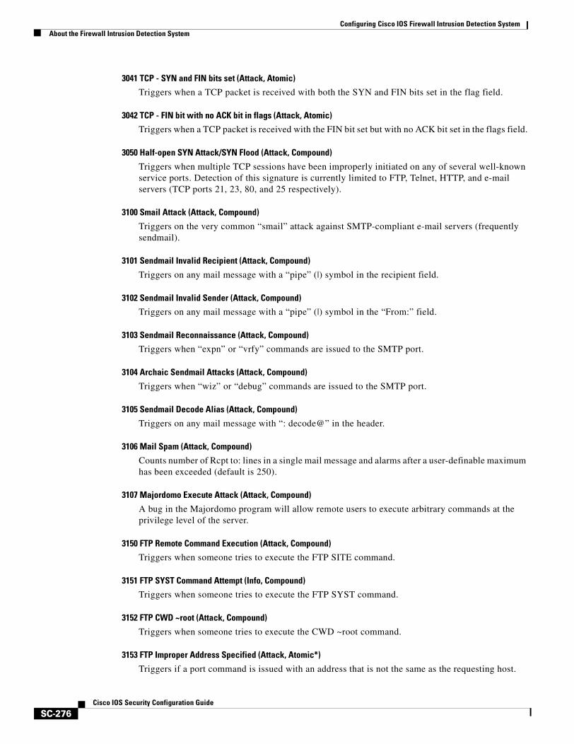
Configuring Cisco IOS Firewall Intrusion Detection SystemAbout the Firewall Intrusion Detection System
SC-276Cisco IOS Security Configuration Guide
3041 TCP - SYN and FIN bits set (Attack, Atomic)
Triggers when a TCP packet is received with both the SYN and FIN bits set in the flag field.
3042 TCP - FIN bit with no ACK bit in flags (Attack, Atomic)
Triggers when a TCP packet is received with the FIN bit set but with no ACK bit set in the flags field.
3050 Half-open SYN Attack/SYN Flood (Attack, Compound)
Triggers when multiple TCP sessions have been improperly initiated on any of several well-known service ports. Detection of this signature is currently limited to FTP, Telnet, HTTP, and e-mail servers (TCP ports 21, 23, 80, and 25 respectively).
3100 Smail Attack (Attack, Compound)
Triggers on the very common “smail” attack against SMTP-compliant e-mail servers (frequently sendmail).
3101 Sendmail Invalid Recipient (Attack, Compound)
Triggers on any mail message with a “pipe” (|) symbol in the recipient field.
3102 Sendmail Invalid Sender (Attack, Compound)
Triggers on any mail message with a “pipe” (|) symbol in the “From:” field.
3103 Sendmail Reconnaissance (Attack, Compound)
Triggers when “expn” or “vrfy” commands are issued to the SMTP port.
3104 Archaic Sendmail Attacks (Attack, Compound)
Triggers when “wiz” or “debug” commands are issued to the SMTP port.
3105 Sendmail Decode Alias (Attack, Compound)
Triggers on any mail message with “: decode@” in the header.
3106 Mail Spam (Attack, Compound)
Counts number of Rcpt to: lines in a single mail message and alarms after a user-definable maximum has been exceeded (default is 250).
3107 Majordomo Execute Attack (Attack, Compound)
A bug in the Majordomo program will allow remote users to execute arbitrary commands at the privilege level of the server.
3150 FTP Remote Command Execution (Attack, Compound)
Triggers when someone tries to execute the FTP SITE command.
3151 FTP SYST Command Attempt (Info, Compound)
Triggers when someone tries to execute the FTP SYST command.
3152 FTP CWD ~root (Attack, Compound)
Triggers when someone tries to execute the CWD ~root command.
3153 FTP Improper Address Specified (Attack, Atomic*)
Triggers if a port command is issued with an address that is not the same as the requesting host.
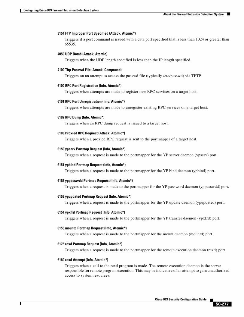
Configuring Cisco IOS Firewall Intrusion Detection SystemAbout the Firewall Intrusion Detection System
SC-277Cisco IOS Security Configuration Guide
3154 FTP Improper Port Specified (Attack, Atomic*)
Triggers if a port command is issued with a data port specified that is less than 1024 or greater than 65535.
4050 UDP Bomb (Attack, Atomic)
Triggers when the UDP length specified is less than the IP length specified.
4100 Tftp Passwd File (Attack, Compound)
Triggers on an attempt to access the passwd file (typically /etc/passwd) via TFTP.
6100 RPC Port Registration (Info, Atomic*)
Triggers when attempts are made to register new RPC services on a target host.
6101 RPC Port Unregistration (Info, Atomic*)
Triggers when attempts are made to unregister existing RPC services on a target host.
6102 RPC Dump (Info, Atomic*)
Triggers when an RPC dump request is issued to a target host.
6103 Proxied RPC Request (Attack, Atomic*)
Triggers when a proxied RPC request is sent to the portmapper of a target host.
6150 ypserv Portmap Request (Info, Atomic*)
Triggers when a request is made to the portmapper for the YP server daemon (ypserv) port.
6151 ypbind Portmap Request (Info, Atomic*)
Triggers when a request is made to the portmapper for the YP bind daemon (ypbind) port.
6152 yppasswdd Portmap Request (Info, Atomic*)
Triggers when a request is made to the portmapper for the YP password daemon (yppasswdd) port.
6153 ypupdated Portmap Request (Info, Atomic*)
Triggers when a request is made to the portmapper for the YP update daemon (ypupdated) port.
6154 ypxfrd Portmap Request (Info, Atomic*)
Triggers when a request is made to the portmapper for the YP transfer daemon (ypxfrd) port.
6155 mountd Portmap Request (Info, Atomic*)
Triggers when a request is made to the portmapper for the mount daemon (mountd) port.
6175 rexd Portmap Request (Info, Atomic*)
Triggers when a request is made to the portmapper for the remote execution daemon (rexd) port.
6180 rexd Attempt (Info, Atomic*)
Triggers when a call to the rexd program is made. The remote execution daemon is the server responsible for remote program execution. This may be indicative of an attempt to gain unauthorized access to system resources.
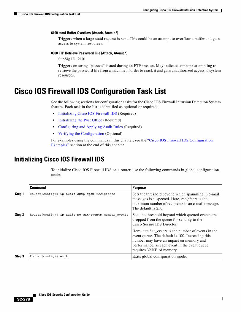
Configuring Cisco IOS Firewall Intrusion Detection SystemCisco IOS Firewall IDS Configuration Task List
SC-278Cisco IOS Security Configuration Guide
6190 statd Buffer Overflow (Attack, Atomic*)
Triggers when a large statd request is sent. This could be an attempt to overflow a buffer and gain access to system resources.
8000 FTP Retrieve Password File (Attack, Atomic*)
SubSig ID: 2101
Triggers on string “passwd” issued during an FTP session. May indicate someone attempting to retrieve the password file from a machine in order to crack it and gain unauthorized access to system resources.
Cisco IOS Firewall IDS Configuration Task ListSee the following sections for configuration tasks for the Cisco IOS Firewall Intrusion Detection System feature. Each task in the list is identified as optional or required:
• Initializing Cisco IOS Firewall IDS (Required)
• Initializing the Post Office (Required)
• Configuring and Applying Audit Rules (Required)
• Verifying the Configuration (Optional)
For examples using the commands in this chapter, see the “Cisco IOS Firewall IDS Configuration Examples” section at the end of this chapter.
Initializing Cisco IOS Firewall IDSTo initialize Cisco IOS Firewall IDS on a router, use the following commands in global configuration mode:
Command Purpose
Step 1 Router(config)# ip audit smtp spam recipients Sets the threshold beyond which spamming in e-mail messages is suspected. Here, recipients is the maximum number of recipients in an e-mail message. The default is 250.
Step 2 Router(config)# ip audit po max-events number_events Sets the threshold beyond which queued events are dropped from the queue for sending to the Cisco Secure IDS Director.
Here, number_events is the number of events in the event queue. The default is 100. Increasing this number may have an impact on memory and performance, as each event in the event queue requires 32 KB of memory.
Step 3 Router(config)# exit Exits global configuration mode.
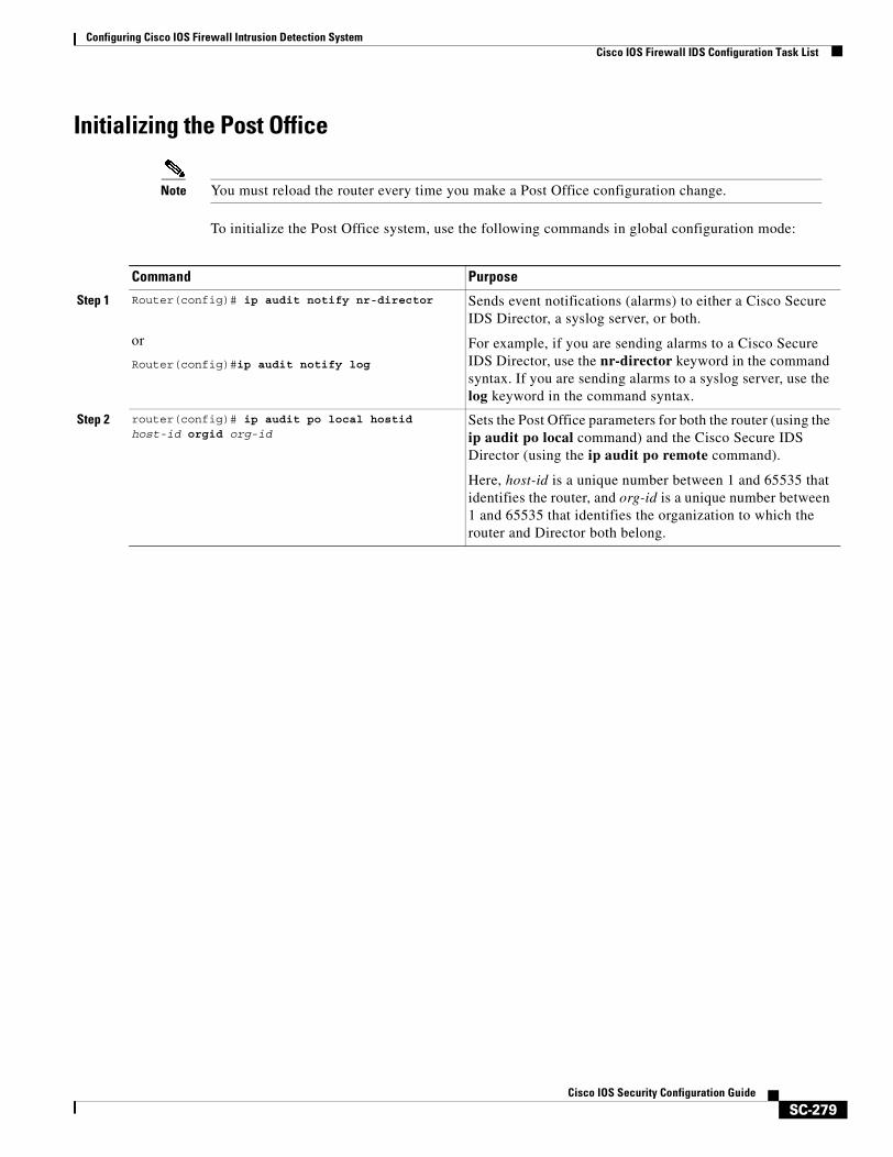
Configuring Cisco IOS Firewall Intrusion Detection SystemCisco IOS Firewall IDS Configuration Task List
SC-279Cisco IOS Security Configuration Guide
Initializing the Post Office
Note You must reload the router every time you make a Post Office configuration change.
To initialize the Post Office system, use the following commands in global configuration mode:
Command Purpose
Step 1 Router(config)# ip audit notify nr-director
or
Router(config)#ip audit notify log
Sends event notifications (alarms) to either a Cisco Secure IDS Director, a syslog server, or both.
For example, if you are sending alarms to a Cisco Secure IDS Director, use the nr-director keyword in the command syntax. If you are sending alarms to a syslog server, use the log keyword in the command syntax.
Step 2 router(config)# ip audit po local hostid host-id orgid org-id
Sets the Post Office parameters for both the router (using the ip audit po local command) and the Cisco Secure IDS Director (using the ip audit po remote command).
Here, host-id is a unique number between 1 and 65535 that identifies the router, and org-id is a unique number between 1 and 65535 that identifies the organization to which the router and Director both belong.
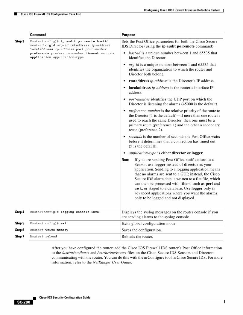
Configuring Cisco IOS Firewall Intrusion Detection SystemCisco IOS Firewall IDS Configuration Task List
SC-280Cisco IOS Security Configuration Guide
After you have configured the router, add the Cisco IOS Firewall IDS router’s Post Office information to the /usr/nr/etc/hosts and /usr/nr/etc/routes files on the Cisco Secure IDS Sensors and Directors communicating with the router. You can do this with the nrConfigure tool in Cisco Secure IDS. For more information, refer to the NetRanger User Guide.
Step 3 Router(config)# ip audit po remote hostid host-id orgid org-id rmtaddress ip-address localaddress ip-address port port-number preference preference-number timeout seconds application application-type
Sets the Post Office parameters for both the Cisco Secure IDS Director (using the ip audit po remote command).
• host-id is a unique number between 1 and 65535 that identifies the Director.
• org-id is a unique number between 1 and 65535 that identifies the organization to which the router and Director both belong.
• rmtaddress ip-address is the Director’s IP address.
• localaddress ip-address is the router’s interface IP address.
• port-number identifies the UDP port on which the Director is listening for alarms (45000 is the default).
• preference-number is the relative priority of the route to the Director (1 is the default)—if more than one route is used to reach the same Director, then one must be a primary route (preference 1) and the other a secondary route (preference 2).
• seconds is the number of seconds the Post Office waits before it determines that a connection has timed out (5 is the default).
• application-type is either director or logger.
Note If you are sending Post Office notifications to a Sensor, use logger instead of director as your application. Sending to a logging application means that no alarms are sent to a GUI; instead, the Cisco Secure IDS alarm data is written to a flat file, which can then be processed with filters, such as perl and awk, or staged to a database. Use logger only in advanced applications where you want the alarms only to be logged and not displayed.
Step 4 Router(config)# logging console info Displays the syslog messages on the router console if you are sending alarms to the syslog console.
Step 5 Router(config)# exit Exits global configuration mode.
Step 6 Router# write memory Saves the configuration.
Step 7 Router# reload Reloads the router.
Command Purpose
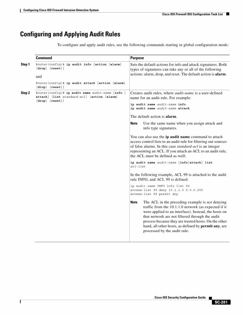
Configuring Cisco IOS Firewall Intrusion Detection SystemCisco IOS Firewall IDS Configuration Task List
SC-281Cisco IOS Security Configuration Guide
Configuring and Applying Audit RulesTo configure and apply audit rules, use the following commands starting in global configuration mode:
Command Purpose
Step 1 Router(config)# ip audit info {action [alarm] [drop] [reset]}
and
Router(config)# ip audit attack {action [alarm] [drop] [reset]}
Sets the default actions for info and attack signatures. Both types of signatures can take any or all of the following actions: alarm, drop, and reset. The default action is alarm.
Step 2 Router(config)# ip audit name audit-name {info | attack} [list standard-acl] [action [alarm] [drop] [reset]]
Creates audit rules, where audit-name is a user-defined name for an audit rule. For example:
ip audit name audit-name infoip audit name audit-name attack
The default action is alarm.
Note Use the same name when you assign attack and info type signatures.
You can also use the ip audit name command to attach access control lists to an audit rule for filtering out sources of false alarms. In this case standard-acl is an integer representing an ACL. If you attach an ACL to an audit rule, the ACL must be defined as well:
ip audit name audit-name {info|attack} list acl-list
In the following example, ACL 99 is attached to the audit rule INFO, and ACL 99 is defined:
ip audit name INFO info list 99access-list 99 deny 10.1.1.0 0.0.0.255access-list 99 permit any
Note The ACL in the preceding example is not denying traffic from the 10.1.1.0 network (as expected if it were applied to an interface). Instead, the hosts on that network are not filtered through the audit process because they are trusted hosts. On the other hand, all other hosts, as defined by permit any, are processed by the audit rule.
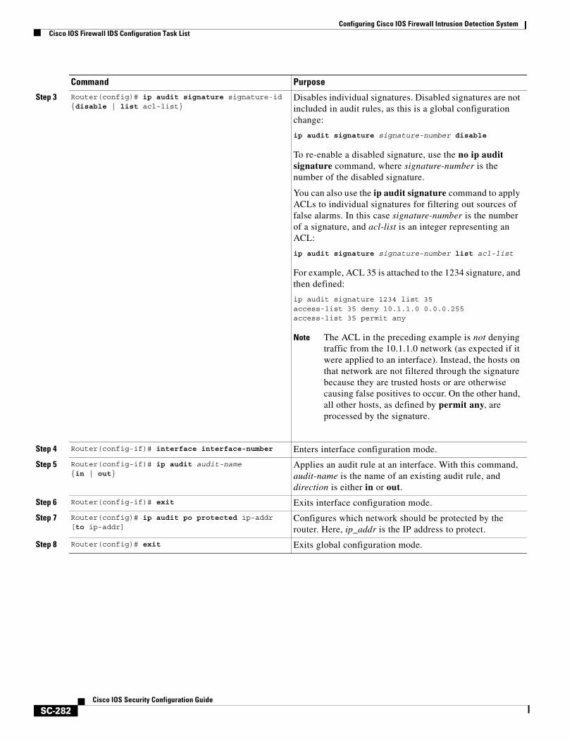
Configuring Cisco IOS Firewall Intrusion Detection SystemCisco IOS Firewall IDS Configuration Task List
SC-282Cisco IOS Security Configuration Guide
Step 3 Router(config)# ip audit signature signature-id {disable | list acl-list}
Disables individual signatures. Disabled signatures are not included in audit rules, as this is a global configuration change:
ip audit signature signature-number disable
To re-enable a disabled signature, use the no ip audit signature command, where signature-number is the number of the disabled signature.
You can also use the ip audit signature command to apply ACLs to individual signatures for filtering out sources of false alarms. In this case signature-number is the number of a signature, and acl-list is an integer representing an ACL:
ip audit signature signature-number list acl-list
For example, ACL 35 is attached to the 1234 signature, and then defined:
ip audit signature 1234 list 35access-list 35 deny 10.1.1.0 0.0.0.255access-list 35 permit any
Note The ACL in the preceding example is not denying traffic from the 10.1.1.0 network (as expected if it were applied to an interface). Instead, the hosts on that network are not filtered through the signature because they are trusted hosts or are otherwise causing false positives to occur. On the other hand, all other hosts, as defined by permit any, are processed by the signature.
Step 4 Router(config-if)# interface interface-number Enters interface configuration mode.
Step 5 Router(config-if)# ip audit audit-name {in | out}
Applies an audit rule at an interface. With this command, audit-name is the name of an existing audit rule, and direction is either in or out.
Step 6 Router(config-if)# exit Exits interface configuration mode.
Step 7 Router(config)# ip audit po protected ip-addr [to ip-addr]
Configures which network should be protected by the router. Here, ip_addr is the IP address to protect.
Step 8 Router(config)# exit Exits global configuration mode.
Command Purpose
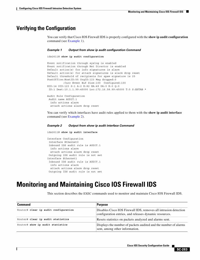
Configuring Cisco IOS Firewall Intrusion Detection SystemMonitoring and Maintaining Cisco IOS Firewall IDS
SC-283Cisco IOS Security Configuration Guide
Verifying the ConfigurationYou can verify that Cisco IOS Firewall IDS is properly configured with the show ip audit configuration command (see Example 1).
Example 1 Output from show ip audit configuration Command
ids2611# show ip audit configuration
Event notification through syslog is enabledEvent notification through Net Director is enabledDefault action(s) for info signatures is alarmDefault action(s) for attack signatures is alarm drop resetDefault threshold of recipients for spam signature is 25PostOffice:HostID:55 OrgID:123 Msg dropped:0 :Curr Event Buf Size:100 Configured:100HID:14 OID:123 S:1 A:2 H:82 HA:49 DA:0 R:0 Q:0ID:1 Dest:10.1.1.99:45000 Loc:172.16.58.99:45000 T:5 S:ESTAB *
Audit Rule ConfigurationAudit name AUDIT.1info actions alarmattack actions alarm drop reset
You can verify which interfaces have audit rules applied to them with the show ip audit interface command (see Example 2).
Example 2 Output from show ip audit interface Command
ids2611# show ip audit interface
Interface ConfigurationInterface Ethernet0Inbound IDS audit rule is AUDIT.1info actions alarmattack actions alarm drop reset
Outgoing IDS audit rule is not setInterface Ethernet1Inbound IDS audit rule is AUDIT.1info actions alarmattack actions alarm drop reset
Outgoing IDS audit rule is not set
Monitoring and Maintaining Cisco IOS Firewall IDSThis section describes the EXEC commands used to monitor and maintain Cisco IOS Firewall IDS.
Command Purpose
Router# clear ip audit configuration Disables Cisco IOS Firewall IDS, removes all intrusion detection configuration entries, and releases dynamic resources.
Router# clear ip audit statistics Resets statistics on packets analyzed and alarms sent.
Router# show ip audit statistics Displays the number of packets audited and the number of alarms sent, among other information.
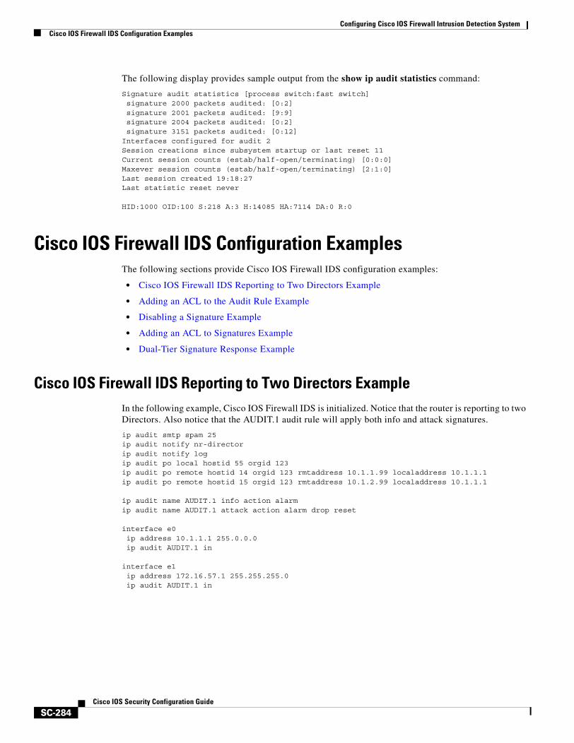
Configuring Cisco IOS Firewall Intrusion Detection SystemCisco IOS Firewall IDS Configuration Examples
SC-284Cisco IOS Security Configuration Guide
The following display provides sample output from the show ip audit statistics command:
Signature audit statistics [process switch:fast switch]signature 2000 packets audited: [0:2]signature 2001 packets audited: [9:9]signature 2004 packets audited: [0:2]signature 3151 packets audited: [0:12]
Interfaces configured for audit 2Session creations since subsystem startup or last reset 11Current session counts (estab/half-open/terminating) [0:0:0]Maxever session counts (estab/half-open/terminating) [2:1:0]Last session created 19:18:27Last statistic reset never HID:1000 OID:100 S:218 A:3 H:14085 HA:7114 DA:0 R:0
Cisco IOS Firewall IDS Configuration ExamplesThe following sections provide Cisco IOS Firewall IDS configuration examples:
• Cisco IOS Firewall IDS Reporting to Two Directors Example
• Adding an ACL to the Audit Rule Example
• Disabling a Signature Example
• Adding an ACL to Signatures Example
• Dual-Tier Signature Response Example
Cisco IOS Firewall IDS Reporting to Two Directors ExampleIn the following example, Cisco IOS Firewall IDS is initialized. Notice that the router is reporting to two Directors. Also notice that the AUDIT.1 audit rule will apply both info and attack signatures.
ip audit smtp spam 25ip audit notify nr-directorip audit notify logip audit po local hostid 55 orgid 123 ip audit po remote hostid 14 orgid 123 rmtaddress 10.1.1.99 localaddress 10.1.1.1 ip audit po remote hostid 15 orgid 123 rmtaddress 10.1.2.99 localaddress 10.1.1.1 ip audit name AUDIT.1 info action alarmip audit name AUDIT.1 attack action alarm drop reset interface e0ip address 10.1.1.1 255.0.0.0ip audit AUDIT.1 in
interface e1ip address 172.16.57.1 255.255.255.0ip audit AUDIT.1 in
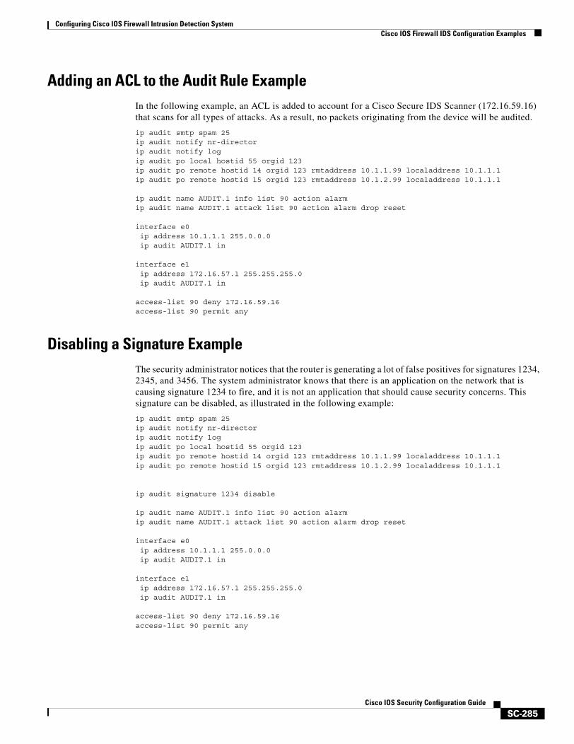
Configuring Cisco IOS Firewall Intrusion Detection SystemCisco IOS Firewall IDS Configuration Examples
SC-285Cisco IOS Security Configuration Guide
Adding an ACL to the Audit Rule ExampleIn the following example, an ACL is added to account for a Cisco Secure IDS Scanner (172.16.59.16) that scans for all types of attacks. As a result, no packets originating from the device will be audited.
ip audit smtp spam 25ip audit notify nr-directorip audit notify logip audit po local hostid 55 orgid 123 ip audit po remote hostid 14 orgid 123 rmtaddress 10.1.1.99 localaddress 10.1.1.1 ip audit po remote hostid 15 orgid 123 rmtaddress 10.1.2.99 localaddress 10.1.1.1 ip audit name AUDIT.1 info list 90 action alarmip audit name AUDIT.1 attack list 90 action alarm drop reset
interface e0ip address 10.1.1.1 255.0.0.0ip audit AUDIT.1 in
interface e1ip address 172.16.57.1 255.255.255.0ip audit AUDIT.1 in
access-list 90 deny 172.16.59.16access-list 90 permit any
Disabling a Signature ExampleThe security administrator notices that the router is generating a lot of false positives for signatures 1234, 2345, and 3456. The system administrator knows that there is an application on the network that is causing signature 1234 to fire, and it is not an application that should cause security concerns. This signature can be disabled, as illustrated in the following example:
ip audit smtp spam 25ip audit notify nr-directorip audit notify logip audit po local hostid 55 orgid 123 ip audit po remote hostid 14 orgid 123 rmtaddress 10.1.1.99 localaddress 10.1.1.1 ip audit po remote hostid 15 orgid 123 rmtaddress 10.1.2.99 localaddress 10.1.1.1
ip audit signature 1234 disable
ip audit name AUDIT.1 info list 90 action alarmip audit name AUDIT.1 attack list 90 action alarm drop reset
interface e0ip address 10.1.1.1 255.0.0.0ip audit AUDIT.1 in
interface e1ip address 172.16.57.1 255.255.255.0ip audit AUDIT.1 in
access-list 90 deny 172.16.59.16access-list 90 permit any
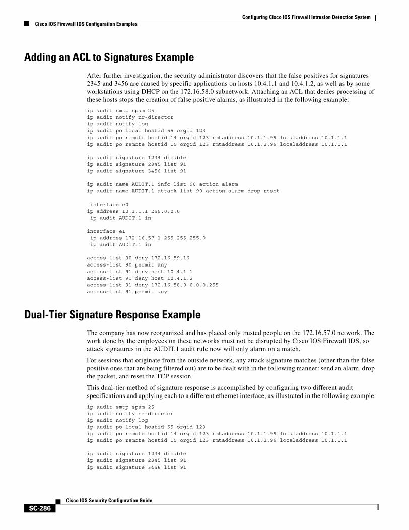
Configuring Cisco IOS Firewall Intrusion Detection SystemCisco IOS Firewall IDS Configuration Examples
SC-286Cisco IOS Security Configuration Guide
Adding an ACL to Signatures ExampleAfter further investigation, the security administrator discovers that the false positives for signatures 2345 and 3456 are caused by specific applications on hosts 10.4.1.1 and 10.4.1.2, as well as by some workstations using DHCP on the 172.16.58.0 subnetwork. Attaching an ACL that denies processing of these hosts stops the creation of false positive alarms, as illustrated in the following example:
ip audit smtp spam 25ip audit notify nr-directorip audit notify logip audit po local hostid 55 orgid 123 ip audit po remote hostid 14 orgid 123 rmtaddress 10.1.1.99 localaddress 10.1.1.1 ip audit po remote hostid 15 orgid 123 rmtaddress 10.1.2.99 localaddress 10.1.1.1
ip audit signature 1234 disableip audit signature 2345 list 91ip audit signature 3456 list 91
ip audit name AUDIT.1 info list 90 action alarmip audit name AUDIT.1 attack list 90 action alarm drop reset
interface e0ip address 10.1.1.1 255.0.0.0ip audit AUDIT.1 in
interface e1ip address 172.16.57.1 255.255.255.0ip audit AUDIT.1 in
access-list 90 deny 172.16.59.16access-list 90 permit anyaccess-list 91 deny host 10.4.1.1access-list 91 deny host 10.4.1.2access-list 91 deny 172.16.58.0 0.0.0.255access-list 91 permit any
Dual-Tier Signature Response ExampleThe company has now reorganized and has placed only trusted people on the 172.16.57.0 network. The work done by the employees on these networks must not be disrupted by Cisco IOS Firewall IDS, so attack signatures in the AUDIT.1 audit rule now will only alarm on a match.
For sessions that originate from the outside network, any attack signature matches (other than the false positive ones that are being filtered out) are to be dealt with in the following manner: send an alarm, drop the packet, and reset the TCP session.
This dual-tier method of signature response is accomplished by configuring two different audit specifications and applying each to a different ethernet interface, as illustrated in the following example:
ip audit smtp spam 25ip audit notify nr-directorip audit notify logip audit po local hostid 55 orgid 123 ip audit po remote hostid 14 orgid 123 rmtaddress 10.1.1.99 localaddress 10.1.1.1 ip audit po remote hostid 15 orgid 123 rmtaddress 10.1.2.99 localaddress 10.1.1.1
ip audit signature 1234 disableip audit signature 2345 list 91ip audit signature 3456 list 91
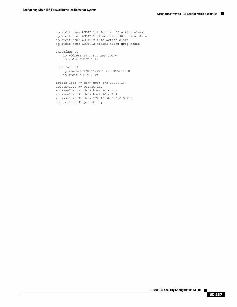
Configuring Cisco IOS Firewall Intrusion Detection SystemCisco IOS Firewall IDS Configuration Examples
SC-287Cisco IOS Security Configuration Guide
ip audit name AUDIT.1 info list 90 action alarmip audit name AUDIT.1 attack list 90 action alarmip audit name AUDIT.2 info action alarmip audit name AUDIT.2 attack alarm drop reset
interface e0ip address 10.1.1.1 255.0.0.0ip audit AUDIT.2 in
interface e1ip address 172.16.57.1 255.255.255.0ip audit AUDIT.1 in
access-list 90 deny host 172.16.59.16access-list 90 permit anyaccess-list 91 deny host 10.4.1.1access-list 91 deny host 10.4.1.2access-list 91 deny 172.16.58.0 0.0.0.255access-list 91 permit any

Configuring Cisco IOS Firewall Intrusion Detection SystemCisco IOS Firewall IDS Configuration Examples
SC-288Cisco IOS Security Configuration Guide
SC-289Cisco IOS Security Configuration Guide
Configuring Authentication Proxy
This chapter describes the Cisco IOS Firewall Authentication Proxy feature. Authentication proxy provides dynamic, per-user authentication and authorization, authenticating users against industry standard TACACS+ and RADIUS authentication protocols. Authenticating and authorizing connections by users provides more robust protection against network attacks.
For a complete description of the authentication proxy commands in this chapter, refer to the “Authentication Proxy Commands” chapter of the Cisco IOS Security Command Reference. To locate documentation of other commands that appear in this chapter, use the command reference master index or search online.
To identify the hardware platform or software image information associated with a feature, use the Feature Navigator on Cisco.com to search for information about the feature or refer to the software release notes for a specific release. For more information, see the “Identifying Supported Platforms” section in the chapter “Using Cisco IOS Software.”
In This ChapterThis chapter contains the following sections:
• About Authentication Proxy
• Authentication Proxy Configuration Task List
• Monitoring and Maintaining the Authentication Proxy
• Authentication Proxy Configuration Examples
About Authentication ProxyThe Cisco IOS Firewall authentication proxy feature allows network administrators to apply specific security policies on a per-user basis. Previously, user identity and related authorized access were associated with a user IP address, or a single security policy had to be applied to an entire user group or subnetwork. Now, users can be identified and authorized on the basis of their per-user policy. Tailoring of access privileges on an individual basis is possible, as opposed to applying a general policy across multiple users.
With the authentication proxy feature, users can log in to the network or access the Internet via HTTP, and their specific access profiles are automatically retrieved and applied from a CiscoSecure ACS, or other RADIUS, or TACACS+ authentication server. The user profiles are active only when there is active traffic from the authenticated users.
Configuring Authentication ProxyAbout Authentication Proxy
SC-290Cisco IOS Security Configuration Guide
The authentication proxy is compatible with other Cisco IOS security features such as Network Address Translation (NAT), Context-based Access Control (CBAC), IP Security (IPSec) encryption, and Cisco Secure VPN Client (VPN client) software.
This section contains the following sections:
• How the Authentication Proxy Works
• Secure Authentication
• Using the Authentication Proxy
• When to Use the Authentication Proxy
• Applying the Authentication Proxy
• Operation with One-Time Passwords
• Compatibility with Other Security Features
• Compatibility with AAA Accounting
• Protection Against Denial-of-Service Attacks
• Risk of Spoofing with Authentication Proxy
• Comparison with the Lock-and-Key Feature
• Restrictions
• Prerequisites to Configuring Authentication Proxy
How the Authentication Proxy WorksWhen a user initiates an HTTP session through the firewall, the authentication proxy is triggered. The authentication proxy first checks to see if the user has been authenticated. If a valid authentication entry exists for the user, the connection is completed with no further intervention by the authentication proxy. If no entry exists, the authentication proxy responds to the HTTP connection request by prompting the user for a username and password.
Figure 23 illustrates the authentication proxy HTML login page.
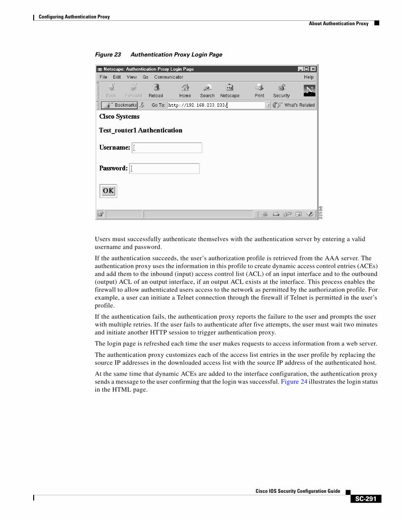
Configuring Authentication ProxyAbout Authentication Proxy
SC-291Cisco IOS Security Configuration Guide
Figure 23 Authentication Proxy Login Page
Users must successfully authenticate themselves with the authentication server by entering a valid username and password.
If the authentication succeeds, the user’s authorization profile is retrieved from the AAA server. The authentication proxy uses the information in this profile to create dynamic access control entries (ACEs) and add them to the inbound (input) access control list (ACL) of an input interface and to the outbound (output) ACL of an output interface, if an output ACL exists at the interface. This process enables the firewall to allow authenticated users access to the network as permitted by the authorization profile. For example, a user can initiate a Telnet connection through the firewall if Telnet is permitted in the user’s profile.
If the authentication fails, the authentication proxy reports the failure to the user and prompts the user with multiple retries. If the user fails to authenticate after five attempts, the user must wait two minutes and initiate another HTTP session to trigger authentication proxy.
The login page is refreshed each time the user makes requests to access information from a web server.
The authentication proxy customizes each of the access list entries in the user profile by replacing the source IP addresses in the downloaded access list with the source IP address of the authenticated host.
At the same time that dynamic ACEs are added to the interface configuration, the authentication proxy sends a message to the user confirming that the login was successful. Figure 24 illustrates the login status in the HTML page.
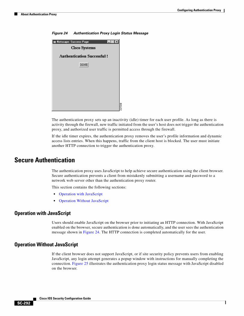
Configuring Authentication ProxyAbout Authentication Proxy
SC-292Cisco IOS Security Configuration Guide
Figure 24 Authentication Proxy Login Status Message
The authentication proxy sets up an inactivity (idle) timer for each user profile. As long as there is activity through the firewall, new traffic initiated from the user’s host does not trigger the authentication proxy, and authorized user traffic is permitted access through the firewall.
If the idle timer expires, the authentication proxy removes the user’s profile information and dynamic access lists entries. When this happens, traffic from the client host is blocked. The user must initiate another HTTP connection to trigger the authentication proxy.
Secure AuthenticationThe authentication proxy uses JavaScript to help achieve secure authentication using the client browser. Secure authentication prevents a client from mistakenly submitting a username and password to a network web server other than the authentication proxy router.
This section contains the following sections:
• Operation with JavaScript
• Operation Without JavaScript
Operation with JavaScript
Users should enable JavaScript on the browser prior to initiating an HTTP connection. With JavaScript enabled on the browser, secure authentication is done automatically, and the user sees the authentication message shown in Figure 24. The HTTP connection is completed automatically for the user.
Operation Without JavaScript
If the client browser does not support JavaScript, or if site security policy prevents users from enabling JavaScript, any login attempt generates a popup window with instructions for manually completing the connection. Figure 25 illustrates the authentication proxy login status message with JavaScript disabled on the browser.
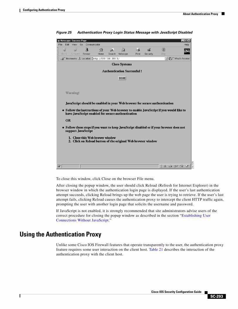
Configuring Authentication ProxyAbout Authentication Proxy
SC-293Cisco IOS Security Configuration Guide
Figure 25 Authentication Proxy Login Status Message with JavaScript Disabled
To close this window, click Close on the browser File menu.
After closing the popup window, the user should click Reload (Refresh for Internet Explorer) in the browser window in which the authentication login page is displayed. If the user’s last authentication attempt succeeds, clicking Reload brings up the web page the user is trying to retrieve. If the user’s last attempt fails, clicking Reload causes the authentication proxy to intercept the client HTTP traffic again, prompting the user with another login page that solicits the username and password.
If JavaScript is not enabled, it is strongly recommended that site administrators advise users of the correct procedure for closing the popup window as described in the section “Establishing User Connections Without JavaScript.”
Using the Authentication ProxyUnlike some Cisco IOS Firewall features that operate transparently to the user, the authentication proxy feature requires some user interaction on the client host. Table 21 describes the interaction of the authentication proxy with the client host.

Configuring Authentication ProxyAbout Authentication Proxy
SC-294Cisco IOS Security Configuration Guide
When to Use the Authentication ProxyHere are examples of situations in which you might use the authentication proxy:
• You want to manage access privileges on an individual (per-user) basis using the services provided by the authentication servers instead of configuring access control based on host IP address or global access policies. Authenticating and authorizing users from any host IP address also allows network administrators to configure host IP addresses using DHCP.
• You want to authenticate and authorize local users before permitting access to intranet or Internet services or hosts through the firewall.
• You want to authenticate and authorize remote users before permitting access to local services or hosts through the firewall.
• You want to control access for specific extranet users. For example, you might want to authenticate and authorize the financial officer of a corporate partner with one set of access privileges while authorizing the technology officer for that same partner to use another set of access privileges.
• You want to use the authentication proxy in conjunction with VPN client software to validate users and to assign specific access privileges.
• You want to use the authentication proxy in conjunction with AAA accounting to generate “start” and “stop” accounting records that can be used for billing, security, or resource allocation purposes, thereby allowing users to track traffic from the authenticated hosts.
Table 21 Authentication Proxy Interaction with the Client Host
Authentication Proxy Action with Client Description
Triggering on HTTP connections If a user is not currently authenticated at the firewall router, any HTTP connection initiated by the user triggers the authentication proxy. If the user is already authenticated, the authentication proxy is transparent to the user.
Logging in using the login page Triggering the authentication proxy generates an HTML-based login page.The user must enter a username and password to be authenticated with the AAA server. Figure 23 illustrates the authentication proxy login page.
Authenticating the user at the client Following the login attempt, the authentication proxy action can vary depending on whether JavaScript is enabled in the browser. If JavaScript is enabled, and authentication is successful, the authentication proxy displays a message indicating the status of the authentication as shown in Figure 24. After the authentication status is displayed, the proxy automatically completes the HTTP connection.
If JavaScript is disabled, and authentication is successful, the authentication proxy generates a popup window with additional instructions for completing the connection. See Figure 25.
If authentication is unsuccessful in any case, the user must log in again from the login page.
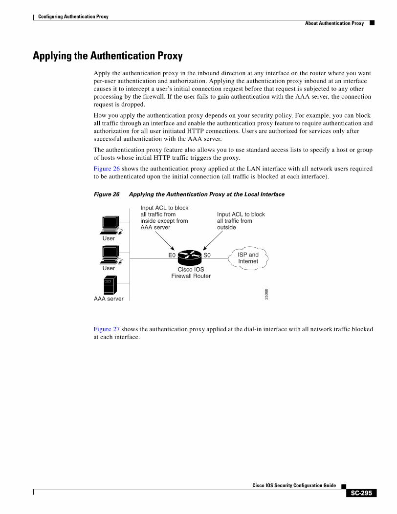
Configuring Authentication ProxyAbout Authentication Proxy
SC-295Cisco IOS Security Configuration Guide
Applying the Authentication ProxyApply the authentication proxy in the inbound direction at any interface on the router where you want per-user authentication and authorization. Applying the authentication proxy inbound at an interface causes it to intercept a user’s initial connection request before that request is subjected to any other processing by the firewall. If the user fails to gain authentication with the AAA server, the connection request is dropped.
How you apply the authentication proxy depends on your security policy. For example, you can block all traffic through an interface and enable the authentication proxy feature to require authentication and authorization for all user initiated HTTP connections. Users are authorized for services only after successful authentication with the AAA server.
The authentication proxy feature also allows you to use standard access lists to specify a host or group of hosts whose initial HTTP traffic triggers the proxy.
Figure 26 shows the authentication proxy applied at the LAN interface with all network users required to be authenticated upon the initial connection (all traffic is blocked at each interface).
Figure 26 Applying the Authentication Proxy at the Local Interface
Figure 27 shows the authentication proxy applied at the dial-in interface with all network traffic blocked at each interface.
2506
8
Input ACL to blockall traffic frominside except fromAAA server
Input ACL to blockall traffic fromoutside
E0 S0 ISP andInternet
User
User
AAA server
Cisco IOSFirewall Router
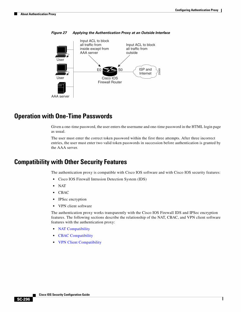
Configuring Authentication ProxyAbout Authentication Proxy
SC-296Cisco IOS Security Configuration Guide
Figure 27 Applying the Authentication Proxy at an Outside Interface
Operation with One-Time PasswordsGiven a one-time password, the user enters the username and one-time password in the HTML login page as usual.
The user must enter the correct token password within the first three attempts. After three incorrect entries, the user must enter two valid token passwords in succession before authentication is granted by the AAA server.
Compatibility with Other Security FeaturesThe authentication proxy is compatible with Cisco IOS software and with Cisco IOS security features:
• Cisco IOS Firewall Intrusion Detection System (IDS)
• NAT
• CBAC
• IPSec encryption
• VPN client software
The authentication proxy works transparently with the Cisco IOS Firewall IDS and IPSec encryption features. The following sections describe the relationship of the NAT, CBAC, and VPN client software features with the authentication proxy:
• NAT Compatibility
• CBAC Compatibility
• VPN Client Compatibility
2506
9
Input ACL to blockall traffic frominside except fromAAA server
Input ACL to blockall traffic fromoutside
E0 S0 ISP andInternet
User
User
AAA server
Cisco IOSFirewall Router
Configuring Authentication ProxyAbout Authentication Proxy
SC-297Cisco IOS Security Configuration Guide
NAT Compatibility
The authentication proxy feature is compatible with NAT; however, to run it successfully with NAT, you must configure CBAC.
For example, when dynamic NAT is configured, the client’s IP address might be translated to different addresses during the time the user is authenticated with the authentication proxy. Assume that the client is running a HTTP session. The user’s original IP address is 10.1.1.1, which is translated by NAT to 192.168.2.2. NAT guarantees that during this session, 10.1.1.1 is always translated to 192.168.2.2. When the user is first authenticated, a set of dynamic ACEs is created to support the user. Subsequent sessions can use different NAT addresses, which are not covered by the original dynamic ACEs created by the authentication proxy. In this case, it is strongly recommended that you configure CBAC to take care of the translated addresses and to create the matching ACEs.
CBAC ensures that the translated address for the session is associated with the original host address.
CBAC Compatibility
To run successfully in all configurations, and to ensure that return traffic for authorized user connections is permitted through the firewall, configure CBAC with the authentication proxy.
Because the authentication proxy does not create ACEs to support return traffic or data channel traffic, you must either create static ACLs to allow the return traffic or configure CBAC inspection rules in the firewall configuration.
VPN Client Compatibility
Using the authentication proxy, network administrators can apply an extra layer of security and access control for VPN client traffic. If a VPN client initiates an HTTP connection, the authentication proxy first checks for prior client authentication. If the client is authenticated, authorized traffic is permitted. If the client is not authenticated, the HTTP request triggers the authentication proxy, and the user is prompted for a username and password.
If the user authentication is successful, the authentication proxy retrieves the user profile from the AAA server. The source address in the user profile entries is replaced with the IP address of the authenticated VPN client from the decrypted packet.
Compatibility with AAA AccountingUsing the authentication proxy, you can generate “start” and “stop” accounting records with enough information to be used for billing and security auditing purposes. Thus, you can monitor the actions of authenticated hosts that use the authentication proxy service.
When an authentication proxy cache and associated dynamic access control lists are created, the authentication proxy will start to track the traffic from the authenticated host. Accounting saves data about this event in a data structure stored with the data of other users. If the accounting start option is enabled, you can generate an accounting record (a “start” record) at this time. Subsequent traffic from the authenticated host will be recorded when the dynamic ACL created by the authentication proxy receives the packets.
When an authentication proxy cache expires and is deleted, additional data, such as elapsed time, is added to the accounting information and a “stop” record is sent to the server. At this point, the information is deleted from the data structure.
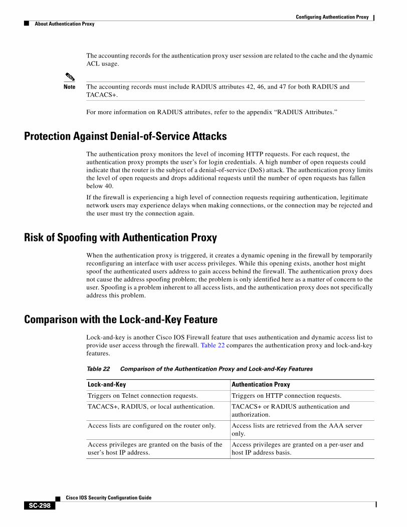
Configuring Authentication ProxyAbout Authentication Proxy
SC-298Cisco IOS Security Configuration Guide
The accounting records for the authentication proxy user session are related to the cache and the dynamic ACL usage.
Note The accounting records must include RADIUS attributes 42, 46, and 47 for both RADIUS and TACACS+.
For more information on RADIUS attributes, refer to the appendix “RADIUS Attributes.”
Protection Against Denial-of-Service AttacksThe authentication proxy monitors the level of incoming HTTP requests. For each request, the authentication proxy prompts the user’s for login credentials. A high number of open requests could indicate that the router is the subject of a denial-of-service (DoS) attack. The authentication proxy limits the level of open requests and drops additional requests until the number of open requests has fallen below 40.
If the firewall is experiencing a high level of connection requests requiring authentication, legitimate network users may experience delays when making connections, or the connection may be rejected and the user must try the connection again.
Risk of Spoofing with Authentication ProxyWhen the authentication proxy is triggered, it creates a dynamic opening in the firewall by temporarily reconfiguring an interface with user access privileges. While this opening exists, another host might spoof the authenticated users address to gain access behind the firewall. The authentication proxy does not cause the address spoofing problem; the problem is only identified here as a matter of concern to the user. Spoofing is a problem inherent to all access lists, and the authentication proxy does not specifically address this problem.
Comparison with the Lock-and-Key FeatureLock-and-key is another Cisco IOS Firewall feature that uses authentication and dynamic access list to provide user access through the firewall. Table 22 compares the authentication proxy and lock-and-key features.
Table 22 Comparison of the Authentication Proxy and Lock-and-Key Features
Lock-and-Key Authentication Proxy
Triggers on Telnet connection requests. Triggers on HTTP connection requests.
TACACS+, RADIUS, or local authentication. TACACS+ or RADIUS authentication and authorization.
Access lists are configured on the router only. Access lists are retrieved from the AAA server only.
Access privileges are granted on the basis of the user’s host IP address.
Access privileges are granted on a per-user and host IP address basis.
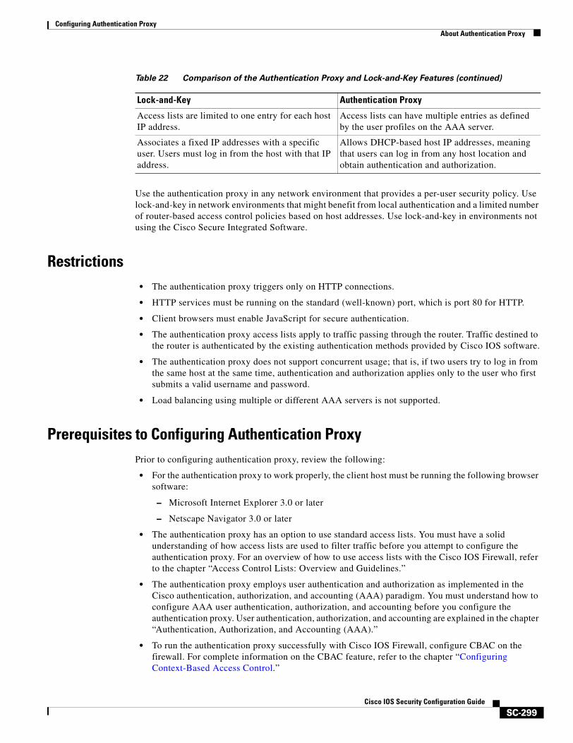
Configuring Authentication ProxyAbout Authentication Proxy
SC-299Cisco IOS Security Configuration Guide
Use the authentication proxy in any network environment that provides a per-user security policy. Use lock-and-key in network environments that might benefit from local authentication and a limited number of router-based access control policies based on host addresses. Use lock-and-key in environments not using the Cisco Secure Integrated Software.
Restrictions• The authentication proxy triggers only on HTTP connections.
• HTTP services must be running on the standard (well-known) port, which is port 80 for HTTP.
• Client browsers must enable JavaScript for secure authentication.
• The authentication proxy access lists apply to traffic passing through the router. Traffic destined to the router is authenticated by the existing authentication methods provided by Cisco IOS software.
• The authentication proxy does not support concurrent usage; that is, if two users try to log in from the same host at the same time, authentication and authorization applies only to the user who first submits a valid username and password.
• Load balancing using multiple or different AAA servers is not supported.
Prerequisites to Configuring Authentication ProxyPrior to configuring authentication proxy, review the following:
• For the authentication proxy to work properly, the client host must be running the following browser software:
– Microsoft Internet Explorer 3.0 or later
– Netscape Navigator 3.0 or later
• The authentication proxy has an option to use standard access lists. You must have a solid understanding of how access lists are used to filter traffic before you attempt to configure the authentication proxy. For an overview of how to use access lists with the Cisco IOS Firewall, refer to the chapter “Access Control Lists: Overview and Guidelines.”
• The authentication proxy employs user authentication and authorization as implemented in the Cisco authentication, authorization, and accounting (AAA) paradigm. You must understand how to configure AAA user authentication, authorization, and accounting before you configure the authentication proxy. User authentication, authorization, and accounting are explained in the chapter “Authentication, Authorization, and Accounting (AAA).”
• To run the authentication proxy successfully with Cisco IOS Firewall, configure CBAC on the firewall. For complete information on the CBAC feature, refer to the chapter “Configuring Context-Based Access Control.”
Access lists are limited to one entry for each host IP address.
Access lists can have multiple entries as defined by the user profiles on the AAA server.
Associates a fixed IP addresses with a specific user. Users must log in from the host with that IP address.
Allows DHCP-based host IP addresses, meaning that users can log in from any host location and obtain authentication and authorization.
Table 22 Comparison of the Authentication Proxy and Lock-and-Key Features (continued)
Lock-and-Key Authentication Proxy
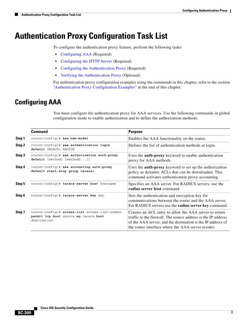
Configuring Authentication ProxyAuthentication Proxy Configuration Task List
SC-300Cisco IOS Security Configuration Guide
Authentication Proxy Configuration Task ListTo configure the authentication proxy feature, perform the following tasks:
• Configuring AAA (Required)
• Configuring the HTTP Server (Required)
• Configuring the Authentication Proxy (Required)
• Verifying the Authentication Proxy (Optional)
For authentication proxy configuration examples using the commands in this chapter, refer to the section “Authentication Proxy Configuration Examples” at the end of this chapter.
Configuring AAAYou must configure the authentication proxy for AAA services. Use the following commands in global configuration mode to enable authorization and to define the authorization methods:
Command Purpose
Step 1 router(config)# aaa new-model Enables the AAA functionality on the router.
Step 2 router(config)# aaa authentication login default TACACS+ RADIUS
Defines the list of authentication methods at login.
Step 3 router(config)# aaa authorization auth-proxy default [method1 [method2...]]
Uses the auth-proxy keyword to enable authentication proxy for AAA methods.
Step 4 router(config)# aaa accounting auth-proxy default start-stop group tacacs+
Uses the auth-proxy keyword to set up the authorization policy as dynamic ACLs that can be downloaded. This command activates authentication proxy accounting.
Step 5 router(config)# tacacs-server host hostname Specifies an AAA server. For RADIUS servers, use the radius server host command.
Step 6 router(config)# tacacs-server key key Sets the authentication and encryption key for communications between the router and the AAA server. For RADIUS servers use the radius server key command.
Step 7 router(config)# access-list access-list-numberpermit tcp host source eq tacacs host destination
Creates an ACL entry to allow the AAA server to return traffic to the firewall. The source address is the IP address of the AAA server, and the destination is the IP address of the router interface where the AAA server resides.

Configuring Authentication ProxyAuthentication Proxy Configuration Task List
SC-301Cisco IOS Security Configuration Guide
In addition to configuring AAA on the firewall router, the authentication proxy requires a per-user access profile configuration on the AAA server. To support the authentication proxy, configure the AAA authorization service auth-proxy on the AAA server as outlined here:
• Define a separate section of authorization for the auth-proxy keyword to specify the downloadable user profiles. This keyword does not interfere with other type of services, such as EXEC. The following example shows a user profile on a TACACS server:
default authorization = permitkey = ciscouser = newuser1 {login = cleartext ciscoservice = auth-proxy{priv-lvl=15proxyacl#1="permit tcp any any eq 26"proxyacl#2="permit icmp any host 60.0.0.2”proxyacl#3="permit tcp any any eq ftp"proxyacl#4="permit tcp any any eq ftp-data"proxyacl#5="permit tcp any any eq smtp"proxyacl#6="permit tcp any any eq telnet"}}
• The only supported attribute in the AAA server user configuration is proxyacl#n. Use the proxyacl#n attribute when configuring the access lists in the profile. The attribute proxyacl#n is for both RADIUS and TACACS+ attribute-value (AV) pairs.
• The privilege level must be set to 15 for all users.
• The access lists in the user profile on the AAA server must have access commands that contain only the permit keyword.
• Set the source address to the any keyword in each of the user profile access list entries. The source address in the access lists is replaced with the source address of the host making the authentication proxy request when the user profile is downloaded to the firewall.
• The supported AAA servers are:
– CiscoSecure ACS 2.1.x for Windows NT
– CiscoSecure ACS 2.3 for Windows NT
– CiscoSecure ACS 2.2.4 for UNIX
– CiscoSecure ACS 2.3 for UNIX
– TACACS+ server (vF4.02.alpha)
– Ascend RADIUS server radius-980618 (required attribute-value pair patch)
– Livingston RADIUS server (v1.16)
Refer to the section “AAA Server User Profile Example” for sample AAA server configurations.
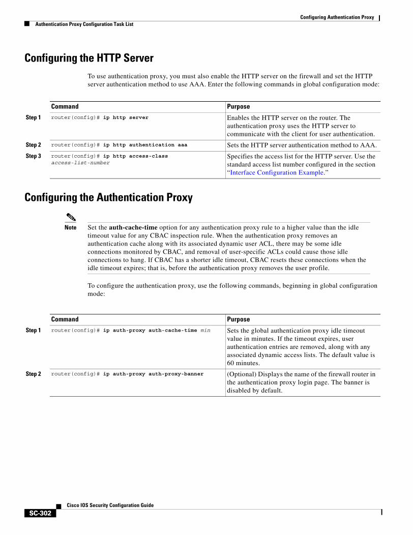
Configuring Authentication ProxyAuthentication Proxy Configuration Task List
SC-302Cisco IOS Security Configuration Guide
Configuring the HTTP Server To use authentication proxy, you must also enable the HTTP server on the firewall and set the HTTP server authentication method to use AAA. Enter the following commands in global configuration mode:
Configuring the Authentication Proxy
Note Set the auth-cache-time option for any authentication proxy rule to a higher value than the idle timeout value for any CBAC inspection rule. When the authentication proxy removes an authentication cache along with its associated dynamic user ACL, there may be some idle connections monitored by CBAC, and removal of user-specific ACLs could cause those idle connections to hang. If CBAC has a shorter idle timeout, CBAC resets these connections when the idle timeout expires; that is, before the authentication proxy removes the user profile.
To configure the authentication proxy, use the following commands, beginning in global configuration mode:
Command Purpose
Step 1 router(config)# ip http server Enables the HTTP server on the router. The authentication proxy uses the HTTP server to communicate with the client for user authentication.
Step 2 router(config)# ip http authentication aaa Sets the HTTP server authentication method to AAA.
Step 3 router(config)# ip http access-class access-list-number
Specifies the access list for the HTTP server. Use the standard access list number configured in the section “Interface Configuration Example.”
Command Purpose
Step 1 router(config)# ip auth-proxy auth-cache-time min Sets the global authentication proxy idle timeout value in minutes. If the timeout expires, user authentication entries are removed, along with any associated dynamic access lists. The default value is 60 minutes.
Step 2 router(config)# ip auth-proxy auth-proxy-banner (Optional) Displays the name of the firewall router in the authentication proxy login page. The banner is disabled by default.
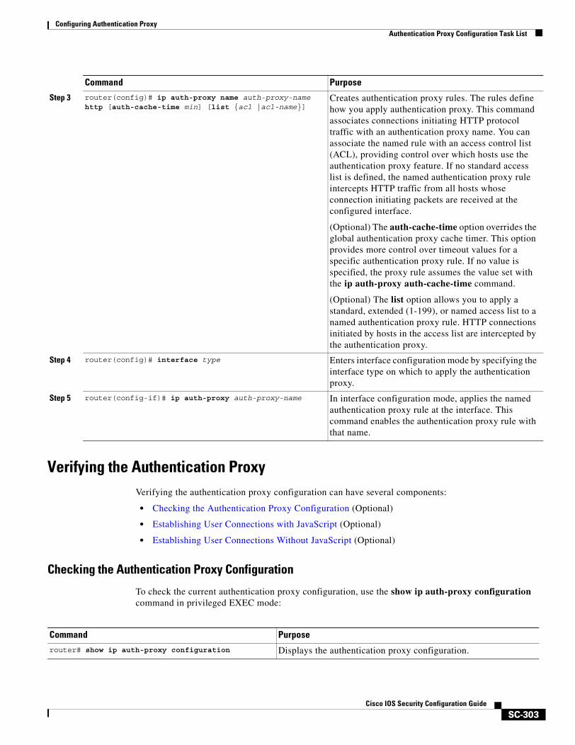
Configuring Authentication ProxyAuthentication Proxy Configuration Task List
SC-303Cisco IOS Security Configuration Guide
Verifying the Authentication ProxyVerifying the authentication proxy configuration can have several components:
• Checking the Authentication Proxy Configuration (Optional)
• Establishing User Connections with JavaScript (Optional)
• Establishing User Connections Without JavaScript (Optional)
Checking the Authentication Proxy Configuration
To check the current authentication proxy configuration, use the show ip auth-proxy configuration command in privileged EXEC mode:
Step 3 router(config)# ip auth-proxy name auth-proxy-name http [auth-cache-time min] [list {acl |acl-name}]
Creates authentication proxy rules. The rules define how you apply authentication proxy. This command associates connections initiating HTTP protocol traffic with an authentication proxy name. You can associate the named rule with an access control list (ACL), providing control over which hosts use the authentication proxy feature. If no standard access list is defined, the named authentication proxy rule intercepts HTTP traffic from all hosts whose connection initiating packets are received at the configured interface.
(Optional) The auth-cache-time option overrides the global authentication proxy cache timer. This option provides more control over timeout values for a specific authentication proxy rule. If no value is specified, the proxy rule assumes the value set with the ip auth-proxy auth-cache-time command.
(Optional) The list option allows you to apply a standard, extended (1-199), or named access list to a named authentication proxy rule. HTTP connections initiated by hosts in the access list are intercepted by the authentication proxy.
Step 4 router(config)# interface type Enters interface configuration mode by specifying the interface type on which to apply the authentication proxy.
Step 5 router(config-if)# ip auth-proxy auth-proxy-name In interface configuration mode, applies the named authentication proxy rule at the interface. This command enables the authentication proxy rule with that name.
Command Purpose
Command Purpose
router# show ip auth-proxy configuration Displays the authentication proxy configuration.
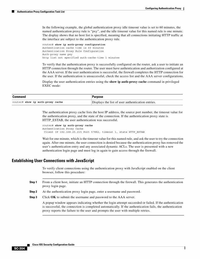
Configuring Authentication ProxyAuthentication Proxy Configuration Task List
SC-304Cisco IOS Security Configuration Guide
In the following example, the global authentication proxy idle timeout value is set to 60 minutes, the named authentication proxy rule is “pxy”, and the idle timeout value for this named rule is one minute. The display shows that no host list is specified, meaning that all connections initiating HTTP traffic at the interface are subject to the authentication proxy rule.
router# show ip auth-proxy configurationAuthentication cache time is 60 minutesAuthentication Proxy Rule ConfigurationAuth-proxy name pxyhttp list not specified auth-cache-time 1 minutes
To verify that the authentication proxy is successfully configured on the router, ask a user to initiate an HTTP connection through the router. The user must have authentication and authorization configured at the AAA server. If the user authentication is successful, the firewall completes the HTTP connection for the user. If the authentication is unsuccessful, check the access list and the AAA server configurations.
Display the user authentication entries using the show ip auth-proxy cache command in privileged EXEC mode:
The authentication proxy cache lists the host IP address, the source port number, the timeout value for the authentication proxy, and the state of the connection. If the authentication proxy state is HTTP_ESTAB, the user authentication was successful.
router# show ip auth-proxy cacheAuthentication Proxy Cache Client IP 192.168.25.215 Port 57882, timeout 1, state HTTP_ESTAB
Wait for one minute, which is the timeout value for this named rule, and ask the user to try the connection again. After one minute, the user connection is denied because the authentication proxy has removed the user’s authentication entry and any associated dynamic ACLs. The user is presented with a new authentication login page and must log in again to gain access through the firewall.
Establishing User Connections with JavaScript
To verify client connections using the authentication proxy with JavaScript enabled on the client browser, follow this procedure:
Step 1 From a client host, initiate an HTTP connection through the firewall. This generates the authentication proxy login page.
Step 2 At the authentication proxy login page, enter a username and password.
Step 3 Click OK to submit the username and password to the AAA server.
A popup window appears indicating whether the login attempt succeeded or failed. If the authentication is successful, the connection is completed automatically. If the authentication fails, the authentication proxy reports the failure to the user and prompts the user with multiple retries.
Command Purpose
router# show ip auth-proxy cache Displays the list of user authentication entries.
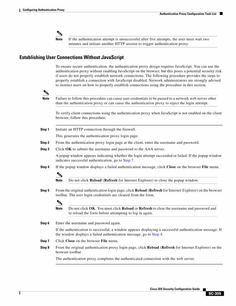
Configuring Authentication ProxyAuthentication Proxy Configuration Task List
SC-305Cisco IOS Security Configuration Guide
Note If the authentication attempt is unsuccessful after five attempts, the user must wait two minutes and initiate another HTTP session to trigger authentication proxy.
Establishing User Connections Without JavaScript
To ensure secure authentication, the authentication proxy design requires JavaScript. You can use the authentication proxy without enabling JavaScript on the browser, but this poses a potential security risk if users do not properly establish network connections. The following procedure provides the steps to properly establish a connection with JavaScript disabled. Network administrators are strongly advised to instruct users on how to properly establish connections using the procedure in this section.
Note Failure to follow this procedure can cause user credentials to be passed to a network web server other than the authentication proxy or can cause the authentication proxy to reject the login attempt.
To verify client connections using the authentication proxy when JavaScript is not enabled on the client browser, follow this procedure:
Step 1 Initiate an HTTP connection through the firewall.
This generates the authentication proxy login page.
Step 2 From the authentication proxy login page at the client, enter the username and password.
Step 3 Click OK to submit the username and password to the AAA server.
A popup window appears indicating whether the login attempt succeeded or failed. If the popup window indicates successful authentication, go to Step 7.
Step 4 If the popup window displays a failed authentication message, click Close on the browser File menu.
Note Do not click Reload (Refresh for Internet Explorer) to close the popup window.
Step 5 From the original authentication login page, click Reload (Refresh for Internet Explorer) on the browser toolbar. The user login credentials are cleared from the form.
Note Do not click OK. You must click Reload or Refresh to clear the username and password and to reload the form before attempting to log in again.
Step 6 Enter the username and password again.
If the authentication is successful, a window appears displaying a successful authentication message. If the window displays a failed authentication message, go to Step 4.
Step 7 Click Close on the browser File menu.
Step 8 From the original authentication proxy login page, click Reload (Refresh for Internet Explorer) on the browser toolbar.
The authentication proxy completes the authenticated connection with the web server.
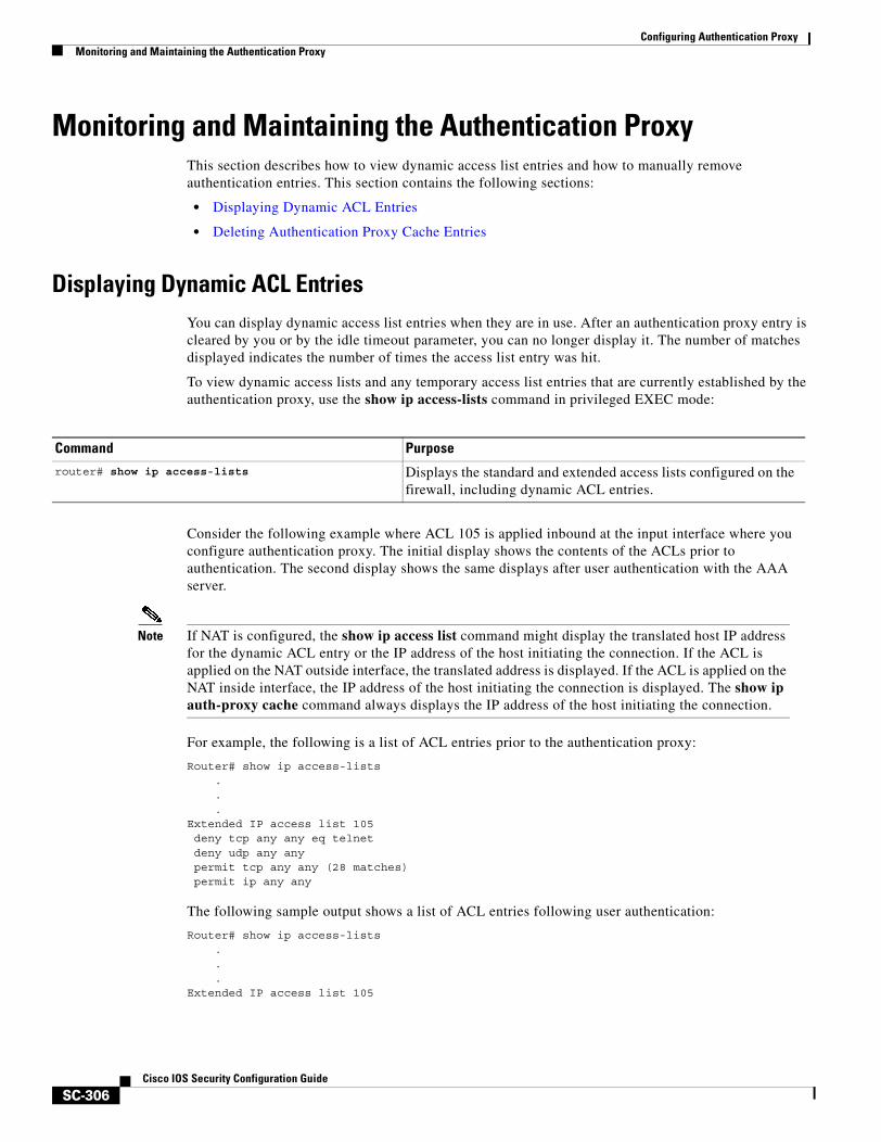
Configuring Authentication ProxyMonitoring and Maintaining the Authentication Proxy
SC-306Cisco IOS Security Configuration Guide
Monitoring and Maintaining the Authentication ProxyThis section describes how to view dynamic access list entries and how to manually remove authentication entries. This section contains the following sections:
• Displaying Dynamic ACL Entries
• Deleting Authentication Proxy Cache Entries
Displaying Dynamic ACL EntriesYou can display dynamic access list entries when they are in use. After an authentication proxy entry is cleared by you or by the idle timeout parameter, you can no longer display it. The number of matches displayed indicates the number of times the access list entry was hit.
To view dynamic access lists and any temporary access list entries that are currently established by the authentication proxy, use the show ip access-lists command in privileged EXEC mode:
Consider the following example where ACL 105 is applied inbound at the input interface where you configure authentication proxy. The initial display shows the contents of the ACLs prior to authentication. The second display shows the same displays after user authentication with the AAA server.
Note If NAT is configured, the show ip access list command might display the translated host IP address for the dynamic ACL entry or the IP address of the host initiating the connection. If the ACL is applied on the NAT outside interface, the translated address is displayed. If the ACL is applied on the NAT inside interface, the IP address of the host initiating the connection is displayed. The show ip auth-proxy cache command always displays the IP address of the host initiating the connection.
For example, the following is a list of ACL entries prior to the authentication proxy:
Router# show ip access-lists...
Extended IP access list 105deny tcp any any eq telnetdeny udp any anypermit tcp any any (28 matches)permit ip any any
The following sample output shows a list of ACL entries following user authentication:
Router# show ip access-lists...
Extended IP access list 105
Command Purpose
router# show ip access-lists Displays the standard and extended access lists configured on the firewall, including dynamic ACL entries.
Configuring Authentication ProxyAuthentication Proxy Configuration Examples
SC-307Cisco IOS Security Configuration Guide
! The ACL entries following user authentication are shown below.permit tcp host 192.168.25.215 any eq 26permit icmp host 192.168.25.215 host 60.0.0.2permit tcp host 192.168.25.215 any eq telnetpermit tcp host 192.168.25.215 any eq ftppermit tcp host 192.168.25.215 any eq ftp-datapermit tcp host 192.168.25.215 any eq smtpdeny tcp any any eq telnetdeny udp any anypermit tcp any any (76 matches)permit ip any any
Deleting Authentication Proxy Cache EntriesWhen the authentication proxy is in use, dynamic access lists dynamically grow and shrink as authentication entries are added and deleted. To display the list of authentication entries, use the show ip auth-proxy cache command. To manually delete an authentication entry, use the clear ip auth-proxy cache command in privileged EXEC mode:
Authentication Proxy Configuration ExamplesConfiguring the authentication proxy feature requires configuration changes on both the router and the AAA server. The following sections provide authentication proxy configuration examples:
• Authentication Proxy Configuration Example
• Authentication Proxy, IPSec, and CBAC Configuration Example
• Authentication Proxy, IPSec, NAT, and CBAC Configuration Example
• AAA Server User Profile Example
Throughout these examples, the exclamation point (!) indicates a comment line. Comment lines precede the configuration entries being described.
Authentication Proxy Configuration ExampleThe following examples highlight the specific authentication proxy configuration entries. These examples do not represent a complete router configuration. Complete router configurations using the authentication proxy are included later in this chapter.
This section contains the following examples:
• AAA Configuration Example
• HTTP Server Configuration Example
• Authentication Proxy Configuration Example
• Interface Configuration Example
Command Purposerouter# clear ip auth-proxy cache {* | host ip address}
Deletes authentication proxy entries from the firewall before they time out. Use an asterisk to delete all authentication cache entries. Enter a specific IP address to delete an entry for a single host.
Configuring Authentication ProxyAuthentication Proxy Configuration Examples
SC-308Cisco IOS Security Configuration Guide
AAA Configuration Example
aaa new-modelaaa authentication login default group tacacs group radius! Set up the aaa new model to use the authentication proxy.aaa authorization auth-proxy default group tacacs group radius! Define the AAA servers used by the router.aaa accounting auth-proxy default start-stop group tacacs+! Set up authentication proxy with accounting.tacacs-server host 172.31.54.143 tacacs-server key ciscoradius-server host 172.31.54.143radius-server key cisco
HTTP Server Configuration Example
! Enable the HTTP server on the router.ip http server! Set the HTTP server authentication method to AAA.ip http authentication aaa! Define standard access list 61 to deny any host.access-list 61 deny any ! Use ACL 61 to deny connections from any host to the HTTP server.ip http access-class 61
Authentication Proxy Configuration Example
! Set the global authentication proxy timeout value.ip auth-proxy auth-cache-time 60! Apply a name to the authentication proxy configuration rule.ip auth-proxy name HQ_users http
Interface Configuration Example
! Apply the authentication proxy rule at an interface.interface e0
ip address 10.1.1.210 255.255.255.0ip auth-proxy HQ_users
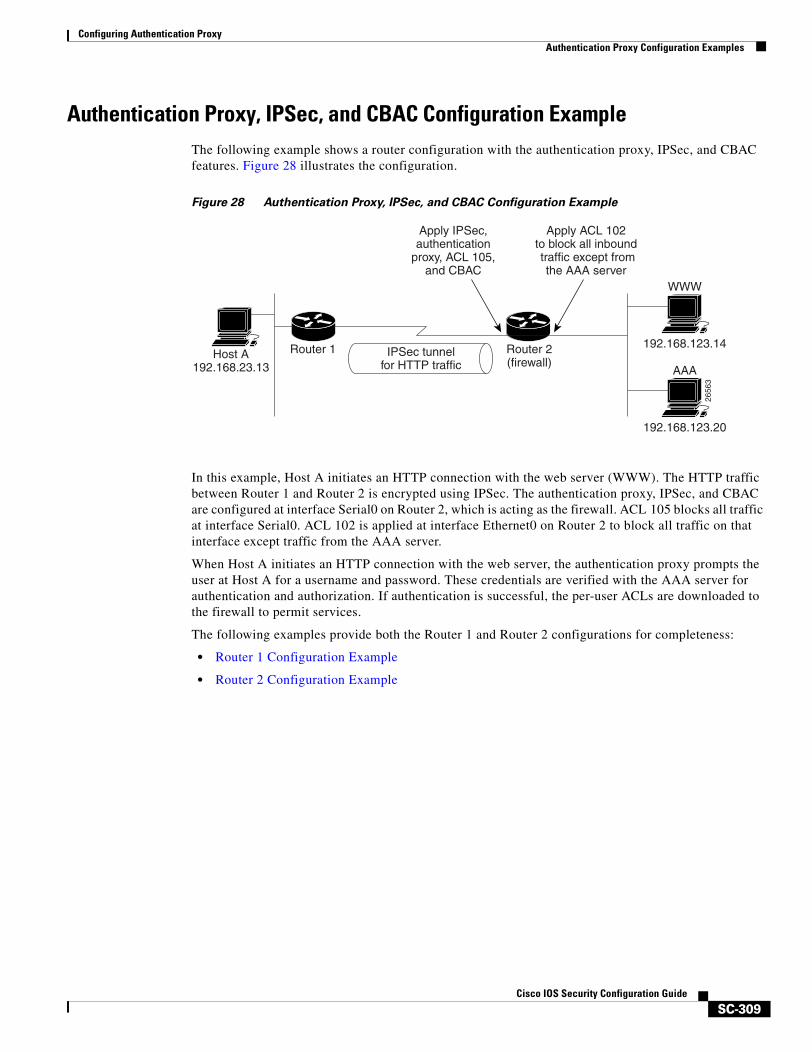
Configuring Authentication ProxyAuthentication Proxy Configuration Examples
SC-309Cisco IOS Security Configuration Guide
Authentication Proxy, IPSec, and CBAC Configuration ExampleThe following example shows a router configuration with the authentication proxy, IPSec, and CBAC features. Figure 28 illustrates the configuration.
Figure 28 Authentication Proxy, IPSec, and CBAC Configuration Example
In this example, Host A initiates an HTTP connection with the web server (WWW). The HTTP traffic between Router 1 and Router 2 is encrypted using IPSec. The authentication proxy, IPSec, and CBAC are configured at interface Serial0 on Router 2, which is acting as the firewall. ACL 105 blocks all traffic at interface Serial0. ACL 102 is applied at interface Ethernet0 on Router 2 to block all traffic on that interface except traffic from the AAA server.
When Host A initiates an HTTP connection with the web server, the authentication proxy prompts the user at Host A for a username and password. These credentials are verified with the AAA server for authentication and authorization. If authentication is successful, the per-user ACLs are downloaded to the firewall to permit services.
The following examples provide both the Router 1 and Router 2 configurations for completeness:
• Router 1 Configuration Example
• Router 2 Configuration Example
Host A192.168.23.13
Router 1
Apply IPSec,authentication
proxy, ACL 105,and CBAC
Apply ACL 102to block all inbound traffic except from
the AAA server
IPSec tunnelfor HTTP traffic
Router 2(firewall)
192.168.123.14
2656
3
192.168.123.20
WWW
AAA
Configuring Authentication ProxyAuthentication Proxy Configuration Examples
SC-310Cisco IOS Security Configuration Guide
Router 1 Configuration Example
! Configure Router 1 for IPSec.version 12.0service timestamps debug uptimeservice timestamps log uptimeno service password-encryption!hostname Router1!logging buffered 4096 debuggingno logging consoleenable secret 5 $1$E0OB$AQF1vFZM3fLr3LQAOsudL/enable password junk!username Router2 password 0 welcomecrypto isakmp policy 1 authentication pre-sharecrypto isakmp key cisco1234 address 10.0.0.2 !crypto ipsec transform-set rule_1 ah-sha-hmac esp-des esp-sha-hmac !! crypto map testtag 10 ipsec-isakmp set peer 10.0.0.2 set transform-set rule_1 match address 155!interface Ethernet0/0 ip address 192.168.23.2 255.255.255.0 no ip directed-broadcast no ip route-cache no ip mroute-cache!interface Serial3/1 ip address 10.0.0.1 255.0.0.0 no ip directed-broadcast encapsulation PPPip route-cache
no ip mroute-cache no keepalive no fair-queue clockrate 56000crypto map testtag
!!ip classlessip route 192.168.123.0 255.255.255.0 10.0.0.2! Identify the IPSec specific traffic.access-list 155 permit tcp host 192.168.23.13 host 192.168.123.14 eq wwwaccess-list 155 permit tcp host 192.168.23.13 eq www host 192.168.123.14
Router 2 Configuration Example
! Configure Router 2 as the firewall, using the authentication proxy, IPSec, and CBAC.version 12.0service timestamps debug uptimeservice timestamps log uptimeno service password-encryption!hostname Router2!
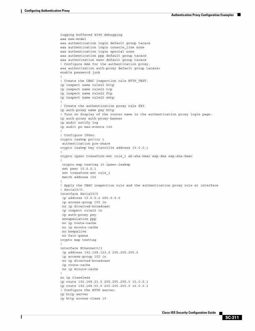
Configuring Authentication ProxyAuthentication Proxy Configuration Examples
SC-311Cisco IOS Security Configuration Guide
logging buffered 4096 debuggingaaa new-modelaaa authentication login default group tacacsaaa authentication login console_line noneaaa authentication login special noneaaa authentication ppp default group tacacsaaa authorization exec default group tacacs! Configure AAA for the authentication proxy.aaa authorization auth-proxy default group tacacs+enable password junk!! Create the CBAC inspection rule HTTP_TEST.ip inspect name rule22 httpip inspect name rule22 tcpip inspect name rule22 ftpip inspect name rule22 smtp!! Create the authentication proxy rule PXY.ip auth-proxy name pxy http! Turn on display of the router name in the authentication proxy login page.ip auth-proxy auth-proxy-bannerip audit notify logip audit po max-events 100!! Configure IPSec.crypto isakmp policy 1 authentication pre-sharecrypto isakmp key cisco1234 address 10.0.0.1 !crypto ipsec transform-set rule_1 ah-sha-hmac esp-des esp-sha-hmac !crypto map testtag 10 ipsec-isakmp
set peer 10.0.0.1 set transform-set rule_1 match address 155!! Apply the CBAC inspection rule and the authentication proxy rule at interface! Serial0/0.interface Serial0/0 ip address 10.0.0.2 255.0.0.0 ip access-group 105 in no ip directed-broadcast ip inspect rule22 in ip auth-proxy pxy encapsulation ppp no ip route-cache no ip mroute-cache no keepalive no fair-queuecrypto map testtag!interface Ethernet0/1 ip address 192.168.123.2 255.255.255.0 ip access-group 102 in no ip directed-broadcastip route-cache
no ip mroute-cache!no ip classlessip route 192.168.23.0 255.255.255.0 10.0.0.1ip route 192.168.50.0 255.255.255.0 16.0.0.1! Configure the HTTP server.ip http serverip http access-class 15
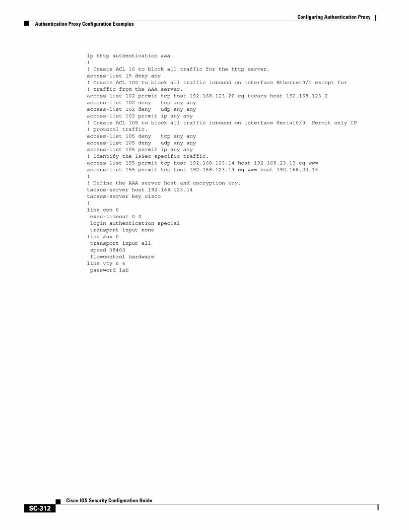
Configuring Authentication ProxyAuthentication Proxy Configuration Examples
SC-312Cisco IOS Security Configuration Guide
ip http authentication aaa!! Create ACL 15 to block all traffic for the http server.access-list 15 deny any! Create ACL 102 to block all traffic inbound on interface Ethernet0/1 except for ! traffic from the AAA server.access-list 102 permit tcp host 192.168.123.20 eq tacacs host 192.168.123.2access-list 102 deny tcp any anyaccess-list 102 deny udp any anyaccess-list 102 permit ip any any! Create ACL 105 to block all traffic inbound on interface Serial0/0. Permit only IP! protocol traffic.access-list 105 deny tcp any anyaccess-list 105 deny udp any anyaccess-list 105 permit ip any any! Identify the IPSec specific traffic.access-list 155 permit tcp host 192.168.123.14 host 192.168.23.13 eq wwwaccess-list 155 permit tcp host 192.168.123.14 eq www host 192.168.23.13!! Define the AAA server host and encryption key.tacacs-server host 192.168.123.14tacacs-server key cisco!line con 0 exec-timeout 0 0 login authentication special transport input noneline aux 0 transport input all speed 38400 flowcontrol hardwareline vty 0 4 password lab
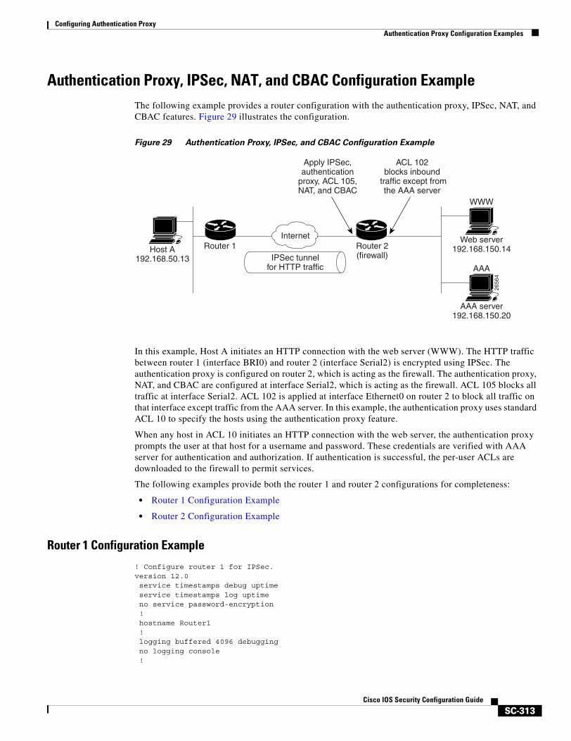
Configuring Authentication ProxyAuthentication Proxy Configuration Examples
SC-313Cisco IOS Security Configuration Guide
Authentication Proxy, IPSec, NAT, and CBAC Configuration ExampleThe following example provides a router configuration with the authentication proxy, IPSec, NAT, and CBAC features. Figure 29 illustrates the configuration.
Figure 29 Authentication Proxy, IPSec, and CBAC Configuration Example
In this example, Host A initiates an HTTP connection with the web server (WWW). The HTTP traffic between router 1 (interface BRI0) and router 2 (interface Serial2) is encrypted using IPSec. The authentication proxy is configured on router 2, which is acting as the firewall. The authentication proxy, NAT, and CBAC are configured at interface Serial2, which is acting as the firewall. ACL 105 blocks all traffic at interface Serial2. ACL 102 is applied at interface Ethernet0 on router 2 to block all traffic on that interface except traffic from the AAA server. In this example, the authentication proxy uses standard ACL 10 to specify the hosts using the authentication proxy feature.
When any host in ACL 10 initiates an HTTP connection with the web server, the authentication proxy prompts the user at that host for a username and password. These credentials are verified with AAA server for authentication and authorization. If authentication is successful, the per-user ACLs are downloaded to the firewall to permit services.
The following examples provide both the router 1 and router 2 configurations for completeness:
• Router 1 Configuration Example
• Router 2 Configuration Example
Router 1 Configuration Example
! Configure router 1 for IPSec.version 12.0 service timestamps debug uptime service timestamps log uptime no service password-encryption ! hostname Router1 ! logging buffered 4096 debugging no logging console !
Host A192.168.50.13
Router 1
Apply IPSec,authentication
proxy, ACL 105,NAT, and CBAC
ACL 102blocks inbound
traffic except fromthe AAA server
Router 2(firewall)
Web server192.168.150.14
IPSec tunnelfor HTTP traffic
2656
4
AAA server192.168.150.20
WWW
AAA
Internet
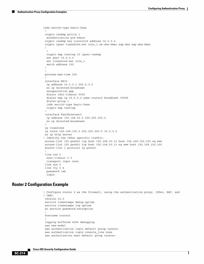
Configuring Authentication ProxyAuthentication Proxy Configuration Examples
SC-314Cisco IOS Security Configuration Guide
isdn switch-type basic-5ess ! crypto isakmp policy 1 authentication pre-share crypto isakmp key cisco1234 address 16.0.0.2 crypto ipsec transform-set rule_1 ah-sha-hmac esp-des esp-sha-hmac ! ! crypto map testtag 10 ipsec-isakmp set peer 16.0.0.2 set transform-set rule_1 match address 155 ! ! process-max-time 200 ! interface BRI0 ip address 16.0.0.1 255.0.0.0
no ip directed-broadcast encapsulation ppp dialer idle-timeout 5000 dialer map ip 16.0.0.2 name router2 broadcast 50006 dialer-group 1 isdn switch-type basic-5ess crypto map testtag ! interface FastEthernet0 ip address 192.168.50.2 255.255.255.0 no ip directed-broadcast!ip classless
ip route 192.168.150.0 255.255.255.0 16.0.0.2 no ip http server! Identify the IPSec specific traffic.access-list 155 permit tcp host 192.168.50.13 host 192.168.150.100 eq www
access-list 155 permit tcp host 192.168.50.13 eq www host 192.168.150.100 dialer-list 1 protocol ip permit ! line con 0 exec-timeout 0 0 transport input none line aux 0 line vty 0 4 password lab login
Router 2 Configuration Example
! Configure router 2 as the firewall, using the authentication proxy, IPSec, NAT, and! CBAC.version 12.0
service timestamps debug uptime service timestamps log uptime no service password-encryption ! hostname router2 ! logging buffered 4096 debugging aaa new-model aaa authentication login default group tacacs+ aaa authentication login console_line none aaa authorization exec default group tacacs+
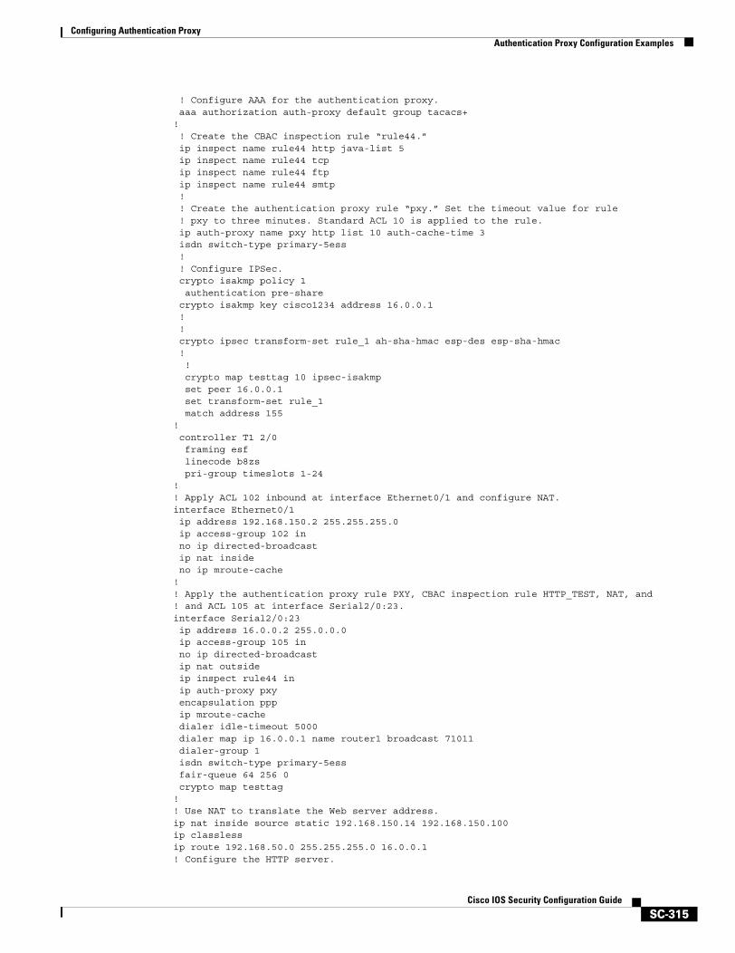
Configuring Authentication ProxyAuthentication Proxy Configuration Examples
SC-315Cisco IOS Security Configuration Guide
! Configure AAA for the authentication proxy.aaa authorization auth-proxy default group tacacs+
!! Create the CBAC inspection rule “rule44.”
ip inspect name rule44 http java-list 5ip inspect name rule44 tcpip inspect name rule44 ftpip inspect name rule44 smtp!! Create the authentication proxy rule “pxy.” Set the timeout value for rule! pxy to three minutes. Standard ACL 10 is applied to the rule.
ip auth-proxy name pxy http list 10 auth-cache-time 3isdn switch-type primary-5ess
! ! Configure IPSec. crypto isakmp policy 1 authentication pre-share crypto isakmp key cisco1234 address 16.0.0.1 ! ! crypto ipsec transform-set rule_1 ah-sha-hmac esp-des esp-sha-hmac ! ! crypto map testtag 10 ipsec-isakmp set peer 16.0.0.1 set transform-set rule_1 match address 155! controller T1 2/0 framing esf linecode b8zs pri-group timeslots 1-24! ! Apply ACL 102 inbound at interface Ethernet0/1 and configure NAT.interface Ethernet0/1ip address 192.168.150.2 255.255.255.0ip access-group 102 inno ip directed-broadcastip nat insideno ip mroute-cache
! ! Apply the authentication proxy rule PXY, CBAC inspection rule HTTP_TEST, NAT, and! and ACL 105 at interface Serial2/0:23.interface Serial2/0:23ip address 16.0.0.2 255.0.0.0ip access-group 105 inno ip directed-broadcastip nat outsideip inspect rule44 inip auth-proxy pxyencapsulation pppip mroute-cachedialer idle-timeout 5000dialer map ip 16.0.0.1 name router1 broadcast 71011dialer-group 1isdn switch-type primary-5essfair-queue 64 256 0crypto map testtag
! ! Use NAT to translate the Web server address.ip nat inside source static 192.168.150.14 192.168.150.100ip classlessip route 192.168.50.0 255.255.255.0 16.0.0.1! Configure the HTTP server.
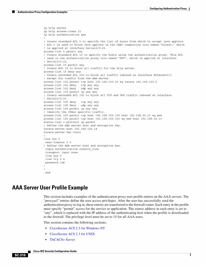
Configuring Authentication ProxyAuthentication Proxy Configuration Examples
SC-316Cisco IOS Security Configuration Guide
ip http serverip http access-class 15ip http authentication aaa!! Create standard ACL 5 to specify the list of hosts from which to accept java applets.! ACL 5 is used to block Java applets in the CBAC inspection rule named “rule44,” which! is applied at interface Serial2/0:23.access-list 5 permit any! Create standard ACL 10 to specify the hosts using the authentication proxy. This ACL! used in the authentication proxy rule named “PXY”, which is applied at interface! Serial2/0:23.access-list 10 permit any! Create ACL 15 to block all traffic for the http server.access-list 15 deny any! Create extended ACL 102 to block all traffic inbound on interface Ethernet0/1! except for traffic from the AAA server.access-list 102 permit tcp host 192.168.150.20 eq tacacs 192.168.150.2access-list 102 deny tcp any anyaccess-list 102 deny udp any anyaccess-list 102 permit ip any any! Create extended ACL 105 to block all TCP and UDP traffic inbound on interface! Serial2/0:23.access-list 105 deny tcp any anyaccess-list 105 deny udp any anyaccess-list 105 permit ip any any! Identify the IPSec specific traffic.access-list 155 permit tcp host 192.168.150.100 host 192.168.50.13 eq wwwaccess-list 155 permit tcp host 192.168.150.100 eq www host 192.168.50.13dialer-list 1 protocol ip permit! Define the AAA server host and encryption key.tacacs-server host 192.168.126.14 tacacs-server key cisco!line con 0exec-timeout 0 0
! Define the AAA server host and encryption key.login authentication console_linetransport input noneline aux 0line vty 0 4password lab
!!end
AAA Server User Profile ExampleThis section includes examples of the authentication proxy user profile entries on the AAA servers. The “proxyacl” entries define the user access privileges. After the user has successfully used the authentication proxy to log in, these entries are transferred to the firewall router. Each entry in the profile must specify “permit” access for the service or application. The source address in each entry is set to “any”, which is replaced with the IP address of the authenticating host when the profile is downloaded to the firewall. The privilege level must be set to 15 for all AAA users.
This section contains the following sections:
• CiscoSecure ACS 2.3 for Windows NT
• CiscoSecure ACS 2.3 for UNIX
• TACACS+ Server
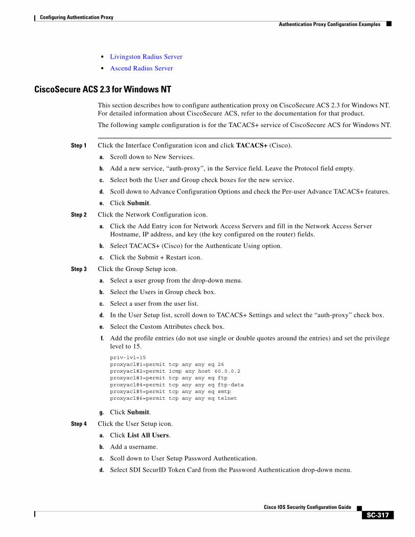
Configuring Authentication ProxyAuthentication Proxy Configuration Examples
SC-317Cisco IOS Security Configuration Guide
• Livingston Radius Server
• Ascend Radius Server
CiscoSecure ACS 2.3 for Windows NT
This section describes how to configure authentication proxy on CiscoSecure ACS 2.3 for Windows NT. For detailed information about CiscoSecure ACS, refer to the documentation for that product.
The following sample configuration is for the TACACS+ service of CiscoSecure ACS for Windows NT.
Step 1 Click the Interface Configuration icon and click TACACS+ (Cisco).
a. Scroll down to New Services.
b. Add a new service, “auth-proxy”, in the Service field. Leave the Protocol field empty.
c. Select both the User and Group check boxes for the new service.
d. Scoll down to Advance Configuration Options and check the Per-user Advance TACACS+ features.
e. Click Submit.
Step 2 Click the Network Configuration icon.
a. Click the Add Entry icon for Network Access Servers and fill in the Network Access Server Hostname, IP address, and key (the key configured on the router) fields.
b. Select TACACS+ (Cisco) for the Authenticate Using option.
c. Click the Submit + Restart icon.
Step 3 Click the Group Setup icon.
a. Select a user group from the drop-down menu.
b. Select the Users in Group check box.
c. Select a user from the user list.
d. In the User Setup list, scroll down to TACACS+ Settings and select the “auth-proxy” check box.
e. Select the Custom Attributes check box.
f. Add the profile entries (do not use single or double quotes around the entries) and set the privilege level to 15.
priv-lvl=15proxyacl#1=permit tcp any any eq 26 proxyacl#2=permit icmp any host 60.0.0.2 proxyacl#3=permit tcp any any eq ftpproxyacl#4=permit tcp any any eq ftp-data proxyacl#5=permit tcp any any eq smtpproxyacl#6=permit tcp any any eq telnet
g. Click Submit.
Step 4 Click the User Setup icon.
a. Click List All Users.
b. Add a username.
c. Scoll down to User Setup Password Authentication.
d. Select SDI SecurID Token Card from the Password Authentication drop-down menu.
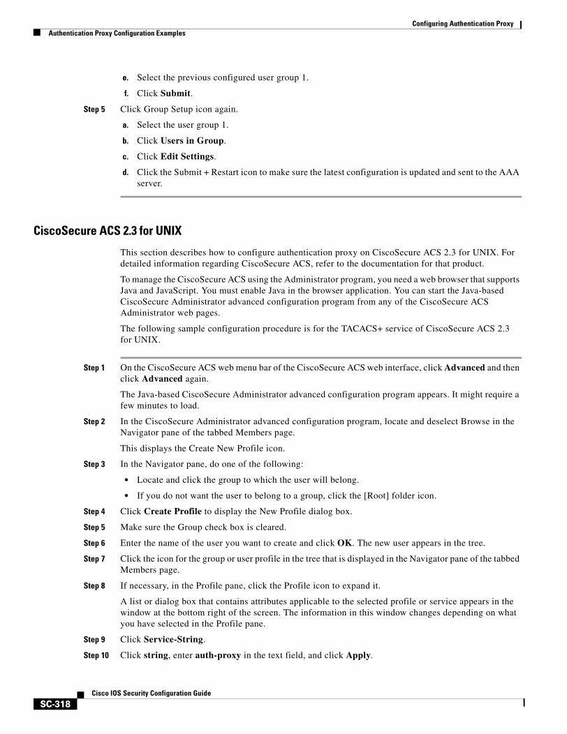
Configuring Authentication ProxyAuthentication Proxy Configuration Examples
SC-318Cisco IOS Security Configuration Guide
e. Select the previous configured user group 1.
f. Click Submit.
Step 5 Click Group Setup icon again.
a. Select the user group 1.
b. Click Users in Group.
c. Click Edit Settings.
d. Click the Submit + Restart icon to make sure the latest configuration is updated and sent to the AAA server.
CiscoSecure ACS 2.3 for UNIX
This section describes how to configure authentication proxy on CiscoSecure ACS 2.3 for UNIX. For detailed information regarding CiscoSecure ACS, refer to the documentation for that product.
To manage the CiscoSecure ACS using the Administrator program, you need a web browser that supports Java and JavaScript. You must enable Java in the browser application. You can start the Java-based CiscoSecure Administrator advanced configuration program from any of the CiscoSecure ACS Administrator web pages.
The following sample configuration procedure is for the TACACS+ service of CiscoSecure ACS 2.3 for UNIX.
Step 1 On the CiscoSecure ACS web menu bar of the CiscoSecure ACS web interface, click Advanced and then click Advanced again.
The Java-based CiscoSecure Administrator advanced configuration program appears. It might require a few minutes to load.
Step 2 In the CiscoSecure Administrator advanced configuration program, locate and deselect Browse in the Navigator pane of the tabbed Members page.
This displays the Create New Profile icon.
Step 3 In the Navigator pane, do one of the following:
• Locate and click the group to which the user will belong.
• If you do not want the user to belong to a group, click the [Root] folder icon.
Step 4 Click Create Profile to display the New Profile dialog box.
Step 5 Make sure the Group check box is cleared.
Step 6 Enter the name of the user you want to create and click OK. The new user appears in the tree.
Step 7 Click the icon for the group or user profile in the tree that is displayed in the Navigator pane of the tabbed Members page.
Step 8 If necessary, in the Profile pane, click the Profile icon to expand it.
A list or dialog box that contains attributes applicable to the selected profile or service appears in the window at the bottom right of the screen. The information in this window changes depending on what you have selected in the Profile pane.
Step 9 Click Service-String.
Step 10 Click string, enter auth-proxy in the text field, and click Apply.
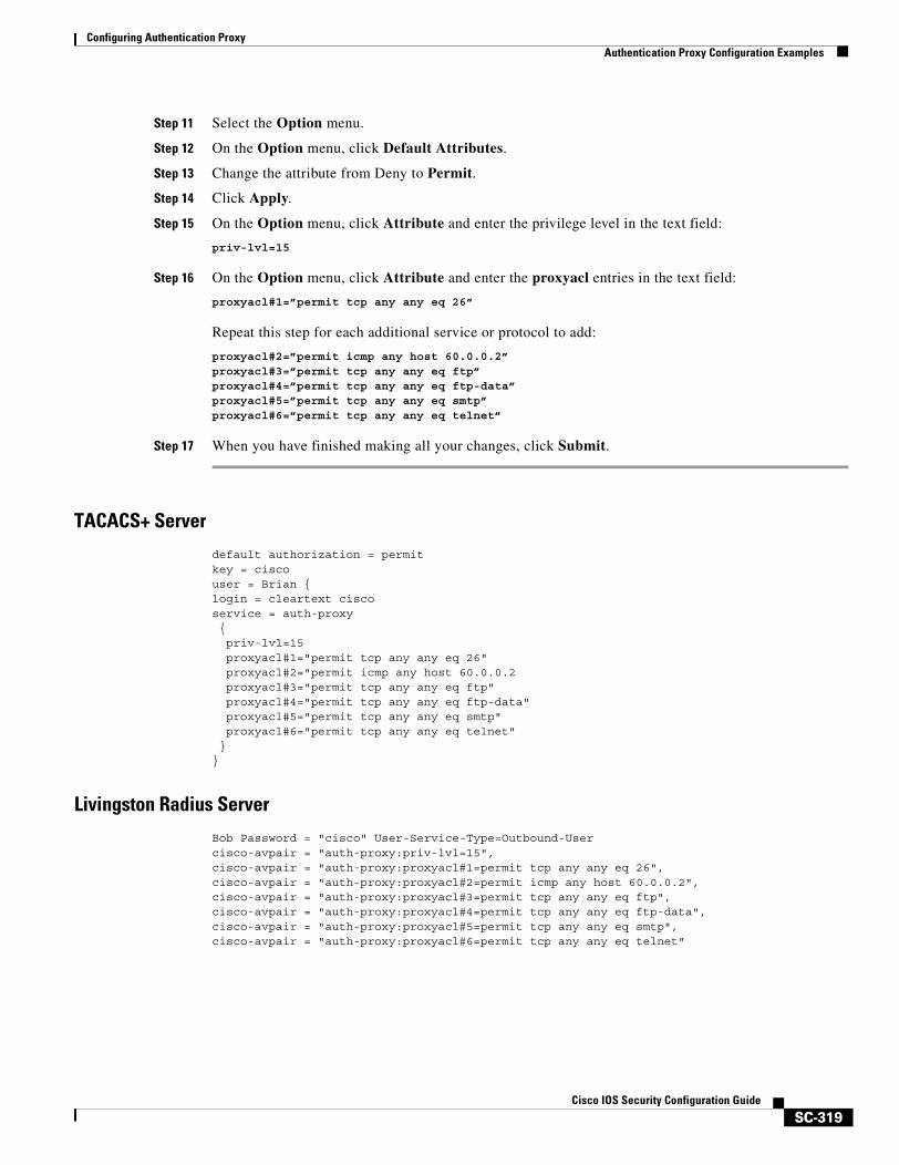
Configuring Authentication ProxyAuthentication Proxy Configuration Examples
SC-319Cisco IOS Security Configuration Guide
Step 11 Select the Option menu.
Step 12 On the Option menu, click Default Attributes.
Step 13 Change the attribute from Deny to Permit.
Step 14 Click Apply.
Step 15 On the Option menu, click Attribute and enter the privilege level in the text field:
priv-lvl=15
Step 16 On the Option menu, click Attribute and enter the proxyacl entries in the text field:
proxyacl#1=”permit tcp any any eq 26”
Repeat this step for each additional service or protocol to add:
proxyacl#2=”permit icmp any host 60.0.0.2” proxyacl#3=”permit tcp any any eq ftp” proxyacl#4=”permit tcp any any eq ftp-data” proxyacl#5=”permit tcp any any eq smtp” proxyacl#6=”permit tcp any any eq telnet”
Step 17 When you have finished making all your changes, click Submit.
TACACS+ Server
default authorization = permitkey = ciscouser = Brian {login = cleartext ciscoservice = auth-proxy{priv-lvl=15proxyacl#1="permit tcp any any eq 26"proxyacl#2="permit icmp any host 60.0.0.2proxyacl#3="permit tcp any any eq ftp"proxyacl#4="permit tcp any any eq ftp-data"proxyacl#5="permit tcp any any eq smtp"proxyacl#6="permit tcp any any eq telnet"
}}
Livingston Radius Server
Bob Password = "cisco" User-Service-Type=Outbound-Usercisco-avpair = "auth-proxy:priv-lvl=15",cisco-avpair = "auth-proxy:proxyacl#1=permit tcp any any eq 26",cisco-avpair = "auth-proxy:proxyacl#2=permit icmp any host 60.0.0.2",cisco-avpair = "auth-proxy:proxyacl#3=permit tcp any any eq ftp",cisco-avpair = "auth-proxy:proxyacl#4=permit tcp any any eq ftp-data",cisco-avpair = "auth-proxy:proxyacl#5=permit tcp any any eq smtp",cisco-avpair = "auth-proxy:proxyacl#6=permit tcp any any eq telnet"

Configuring Authentication ProxyAuthentication Proxy Configuration Examples
SC-320Cisco IOS Security Configuration Guide
Ascend Radius Server
Alice Password = "cisco" User-Service = Dialout-Framed-Usercisco-avpair = "auth-proxy:priv-lvl=15",cisco-avpair = "auth-proxy:proxyacl#1=permit tcp any any eq 26",cisco-avpair = "auth-proxy:proxyacl#2=permit icmp any host 60.0.0.2",cisco-avpair = "auth-proxy:proxyacl#3=permit tcp any any eq ftp",cisco-avpair = "auth-proxy:proxyacl#4=permit tcp any any eq ftp-data",cisco-avpair = "auth-proxy:proxyacl#5=permit tcp any any eq smtp",cisco-avpair = "auth-proxy:proxyacl#6=permit tcp any any eq telnet"
SC-321Cisco IOS Security Configuration Guide
Configuring Port to Application Mapping
This chapter describes the Cisco IOS Firewall Port to Application Mapping (PAM) feature. PAM enables CBAC-supported applications to be run on nonstandard ports. Using PAM, network administrators can customize access control for specific applications and services to meet the distinct needs of their networks.
For a complete description of the PAM commands in this chapter, refer to the chapter “Port to Application Mapping Commands” of the Cisco IOS Security Command Reference. To locate documentation of other commands that appear in this chapter, use the command reference master index or search online.
To identify the hardware platform or software image information associated with a feature, use the Feature Navigator on Cisco.com to search for information about the feature or refer to the software release notes for a specific release. For more information, see the “Identifying Supported Platforms” section in the chapter “Using Cisco IOS Software.”
In This ChapterThis chapter contains the following sections:
• About Port to Application Mapping
• PAM Configuration Task List
• Monitoring and Maintaining PAM
• PAM Configuration Examples
About Port to Application MappingPort to Application Mapping (PAM) is a feature of the Cisco IOS Firewall feature set. PAM allows you to customize TCP or UDP port numbers for network services or applications. PAM uses this information to support network environments that run services using ports that are different from the registered or well-known ports associated with an application.
Using the port information, PAM establishes a table of default port-to-application mapping information at the firewall. The information in the PAM table enables Context-based Access Control (CBAC) supported services to run on nonstandard ports. Previously, CBAC was limited to inspecting traffic using only the well-known or registered ports associated with an application. Now, PAM allows network administrators to customize network access control for specific applications and services.
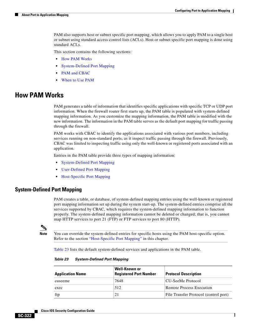
Configuring Port to Application MappingAbout Port to Application Mapping
SC-322Cisco IOS Security Configuration Guide
PAM also supports host or subnet specific port mapping, which allows you to apply PAM to a single host or subnet using standard access control lists (ACLs). Host or subnet specific port mapping is done using standard ACLs.
This section contains the following sections:
• How PAM Works
• System-Defined Port Mapping
• PAM and CBAC
• When to Use PAM
How PAM WorksPAM generates a table of information that identifies specific applications with specific TCP or UDP port information. When the firewall router first starts up, the PAM table is populated with system-defined mapping information. As you customize the mapping information, the PAM table is modified with the new information. The information in the PAM table serves as the default port mapping for traffic passing through the firewall.
PAM works with CBAC to identify the applications associated with various port numbers, including services running on non-standard ports, as it inspect traffic passing through the firewall. Previously, CBAC was limited to inspecting traffic using only the well-known or registered ports associated with an application.
Entries in the PAM table provide three types of mapping information:
• System-Defined Port Mapping
• User-Defined Port Mapping
• Host-Specific Port Mapping
System-Defined Port Mapping
PAM creates a table, or database, of system-defined mapping entries using the well-known or registered port mapping information set up during the system start-up. The system-defined entries comprise all the services supported by CBAC, which requires the system-defined mapping information to function properly. The system-defined mapping information cannot be deleted or changed; that is, you cannot map HTTP services to port 21 (FTP) or FTP services to port 80 (HTTP).
Note You can override the system-defined entries for specific hosts using the PAM host-specific option. Refer to the section “Host-Specific Port Mapping” in this chapter.
Table 23 lists the default system-defined services and applications in the PAM table.
Table 23 System-Defined Port Mapping
Application NameWell-Known orRegistered Port Number Protocol Description
cuseeme 7648 CU-SeeMe Protocol
exec 512 Remote Process Execution
ftp 21 File Transfer Protocol (control port)
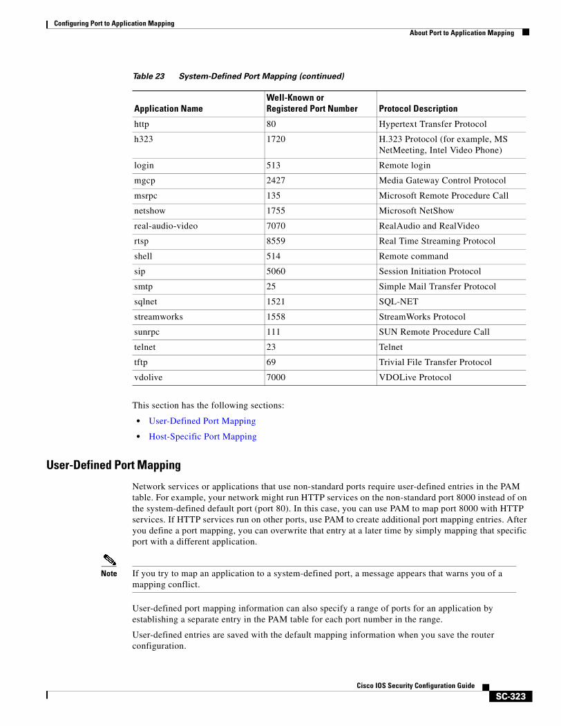
Configuring Port to Application MappingAbout Port to Application Mapping
SC-323Cisco IOS Security Configuration Guide
This section has the following sections:
• User-Defined Port Mapping
• Host-Specific Port Mapping
User-Defined Port Mapping
Network services or applications that use non-standard ports require user-defined entries in the PAM table. For example, your network might run HTTP services on the non-standard port 8000 instead of on the system-defined default port (port 80). In this case, you can use PAM to map port 8000 with HTTP services. If HTTP services run on other ports, use PAM to create additional port mapping entries. After you define a port mapping, you can overwrite that entry at a later time by simply mapping that specific port with a different application.
Note If you try to map an application to a system-defined port, a message appears that warns you of a mapping conflict.
User-defined port mapping information can also specify a range of ports for an application by establishing a separate entry in the PAM table for each port number in the range.
User-defined entries are saved with the default mapping information when you save the router configuration.
http 80 Hypertext Transfer Protocol
h323 1720 H.323 Protocol (for example, MS NetMeeting, Intel Video Phone)
login 513 Remote login
mgcp 2427 Media Gateway Control Protocol
msrpc 135 Microsoft Remote Procedure Call
netshow 1755 Microsoft NetShow
real-audio-video 7070 RealAudio and RealVideo
rtsp 8559 Real Time Streaming Protocol
shell 514 Remote command
sip 5060 Session Initiation Protocol
smtp 25 Simple Mail Transfer Protocol
sqlnet 1521 SQL-NET
streamworks 1558 StreamWorks Protocol
sunrpc 111 SUN Remote Procedure Call
telnet 23 Telnet
tftp 69 Trivial File Transfer Protocol
vdolive 7000 VDOLive Protocol
Table 23 System-Defined Port Mapping (continued)
Application NameWell-Known orRegistered Port Number Protocol Description
Configuring Port to Application MappingPAM Configuration Task List
SC-324Cisco IOS Security Configuration Guide
Host-Specific Port Mapping
User-defined entries in the mapping table can include host-specific mapping information, which establishes port mapping information for specific hosts or subnets. In some environments, it might be necessary to override the default port mapping information for a specific host or subnet.
With host-specific port mapping, you can use the same port number for different services on different hosts. This means that you can map port 8000 with HTTP services for one host, while mapping port 8000 with Telnet services for another host.
Host-specific port mapping also allows you to apply PAM to a specific subnet when that subnet runs a service that uses a port number that is different from the port number defined in the default mapping information. For example, hosts on subnet 192.168.21.0 might run HTTP services on non-standard port 8000, while other traffic through the firewall uses the default port for HTTP services, which is port 80.
Host-specific port mapping allows you to override a system-defined entry in the PAM table. For example, if CBAC finds an entry in the PAM table that maps port 25 (the system-defined port for SMTP) with HTTP for a specific host, CBAC identifies port 25 as HTTP protocol traffic on that host.
Note If the host-specific port mapping information is the same as an existing system-defined or user-defined default entries, host-specific port changes have no effect.
PAM and CBACCBAC uses the information in the PAM table to identify a service or application from traffic flowing through the firewall. With PAM, CBAC can associate non-standard port numbers with specific protocols. For example, if you use PAM to map port 8000 with HTTP services, CBAC can determine that traffic using port 8000 is an HTTP application.
When to Use PAMHere are a few examples of when you might want to use PAM:
• Use PAM to apply a non-standard port numbers for a service or application.
• Use PAM when a specific host or subnet uses a port number for an application that is different than the default port number established in the PAM table.
• Use PAM when different hosts use the same port number for different applications.
PAM Configuration Task ListSee the following sections for PAM configuration tasks. Each task in the list indicates if it is optional or required:
• Configuring Standard ACLs (Optional)
• Configuring PAM (Required)
• Verifying PAM (Optional)
Configuring Port to Application MappingPAM Configuration Task List
SC-325Cisco IOS Security Configuration Guide
Configuring Standard ACLsIf you require PAM for a specific host or subnet, use the access-list (standard) command in global configuration mode to define an ACL:
Configuring PAMTo configure PAM, use the ip port-map command in global configuration mode:
Verifying PAMTo verify the port mapping information, enter the show ip port-map command in privileged EXEC mode and review the entries:
Router# show ip port-map
This command displays all entries in the PAM table, including the system-defined entries.
For PAM configuration examples using the commands in this chapter, refer to the “PAM Configuration Examples” section at the end of this chapter.
Command Purpose
Router(config)# access-list access-list-number permit source [source-wildcard]
(Optional) Creates a standard ACL that defines the specific host or subnet for host-specific PAM.
For complete information on access-list command, refer to the Cisco IOS IP Command Reference, Volume 1 of 3: Addressing and Services.
Command Purpose
Router(config)# ip port-map appl_name port port_num [list acl_num]
Establishes a port mapping entry using the TCP or UDP port number and the application name.
(Optional) Use the list option to associate this port mapping to the specific hosts in the ACL. (PAM uses standard access lists only.) If an access list is included, the hosts defined in that ACL have the application appl_name running on port port_num.
Configuring Port to Application MappingMonitoring and Maintaining PAM
SC-326Cisco IOS Security Configuration Guide
Monitoring and Maintaining PAMThe following commands can be used to monitor and maintain PAM:
PAM Configuration ExamplesThe following sections provide PAM configuration examples:
• Mapping an Application to a Non-Standard Port Example
• Mapping an Application with a Port Range Example
• Invalid Port Mapping Entry Example
• Mapping an Application to a Port for a Specific Host Example
• Mapping an Application to a Port for a Subnet Example
• Overriding a System-Defined Port Mapping Example
• Mapping Different Applications to the Same Port Example
Mapping an Application to a Non-Standard Port ExampleIn this example, non-standard port 8000 is established as the user-defined default port mapping for HTTP services:
ip port-map http port 8000
Mapping an Application with a Port Range ExampleThe following PAM entries establish a range of non-standard ports for HTTP services:
ip port-map http 8001ip port-map http 8002ip port-map http 8003ip port-map http 8004
Invalid Port Mapping Entry ExampleThis example is not valid because it tries to establish port 21, which is the system-defined default port for FTP, as the user-defined port for HTTP services:
Command Purpose
Router# show ip port-map [appl_name | port port_num] Displays the port mapping information, including the system-defined entries. Include the application name to display a list of entries by application. Include the port number to display the entries by port.
Router(config)# no ip port-map appl_name port port_num [list acl_num]
Deletes user-defined port mapping information. This command has no effect on the system-defined port mapping information.
Configuring Port to Application MappingPAM Configuration Examples
SC-327Cisco IOS Security Configuration Guide
ip port-map http port 21
Mapping an Application to a Port for a Specific Host ExampleIn this example, a specific host uses port 8000 for FTP services. ACL 10 identifies the server address (192.168.32.43), while port 8000 is mapped with FTP services.
access-list 10 permit 192.168.32.43ip port-map ftp port 8000 list 10
Mapping an Application to a Port for a Subnet ExampleIn this example, a specific subnet runs HTTP services on port 8080. ACL 50 identifies the subnet, while port 8080 is mapped with HTTP services.
access-list 50 permit 192.168.92.0 0.0.0.255ip port-map http 8080 list 50
Overriding a System-Defined Port Mapping ExampleIn this example, a specific host runs HTTP services on port 25, which is the system-defined port number for SMTP services. This requires a host-specific PAM entry that overrides the system-defined default port mapping for HTTP, which is port 80. ACL 15 identifies the host address (192.168.33.33), while port 25 is mapped with HTTP services.
access-list 15 permit 192.168.33.33ip port-map http port 25 list 15
Mapping Different Applications to the Same Port ExampleIn this example, the same port number is required by different services running on different hosts. Port 8000 is required for HTTP services for host 192.168.3.4, while port 8000 is also required for FTP services for host 192.168.5.6. ACL 10 and ACL 20 identify the specific hosts, while the PAM entries map the ports with the services for each ACL.
access-list 10 permit 192.168.3.4access-list 20 permit 192.168.5.6ip port-map http port 8000 list 10ip port-map http ftp 8000 list 20

Configuring Port to Application MappingPAM Configuration Examples
SC-328Cisco IOS Security Configuration Guide

IP Security and Encryption

SC-331Cisco IOS Security Configuration Guide
IP Security and Encryption Overview
This chapter briefly describes the following security features and how they relate to each other:
• IPSec Network Security
• Certification Authority Interoperability
• Internet Key Exchange Security Protocol
IPSec Network SecurityIPSec is a framework of open standards developed by the Internet Engineering Task Force (IETF) that provides security for transmission of sensitive information over unprotected networks such as the Internet. It acts at the network level and implements the following standards:
• IPSec
• Internet Key Exchange (IKE)
• Data Encryption Standard (DES)
• MD5 (HMAC variant)
• SHA (HMAC variant)
• Authentication Header (AH)
• Encapsulating Security Payload (ESP)
IPSec services provide a robust security solution that is standards-based. IPSec also provides data authentication and anti-replay services in addition to data confidentiality services.
For more information regarding IPSec, refer to the chapter “Configuring IPSec Network Security.”
IPSec Encryption TechnologyIPSec protects sensitive data that travels across unprotected networks. IPSec security services are provided at the network layer, so you do not have to configure individual workstations, PCs, or applications. This benefit can provide a great cost savings. Instead of providing the security services you do not need to deploy and coordinate security on a per-application, per-computer basis, you can simply change the network infrastructure to provide the needed security services.

IP Security and Encryption OverviewCertification Authority Interoperability
SC-332Cisco IOS Security Configuration Guide
IPSec encryption offers a number of additional benefits:
• Because IPSec is standards-based, enables Cisco devices to interoperate with other IPSec-compliant networking devices to provide the IPSec security services. IPSec-compliant devices could include both Cisco devices and non-Cisco devices such as PCs, servers, and other computing systems.
Cisco and its partners, including Microsoft, are planning to offer IPSec across a wide range of platforms, including Cisco IOS software, the Cisco PIX Firewall, and Windows 2000.
• Enables a mobile user to establish a secure connection back to the office. For example, the user can establish an IPSec “tunnel” with a corporate firewall—requesting authentication services—in order to gain access to the corporate network; all of the traffic between the user and the firewall will then be authenticated. The user can then establish an additional IPSec tunnel—requesting data privacy services—with an internal router or end system.
• Provides support for the Internet Key Exchange (IKE) protocol and for digital certificates. IKE provides negotiation services and key derivation services for IPSec. Digital certificates allow devices to be automatically authenticated to each other without manual key exchanges.
Certification Authority InteroperabilityCertification Authority (CA) interoperability is provided in support of the IPSec standard. It permits Cisco IOS devices and CAs to communicate so that your Cisco IOS device can obtain and use digital certificates from the CA. Although IPSec can be implemented in your network without the use of a CA, using a CA provides manageability and scalability for IPSec.
For more information regarding CA interoperability, refer to the chapter “Configuring Certification Authority Interoperability.”
Internet Key Exchange Security ProtocolInternet Key Exchange (IKE) security protocol is a key management protocol standard that is used in conjunction with the IPSec standard. IPSec can be configured without IKE, but IKE enhances IPSec by providing additional features, flexibility, and ease of configuration for the IPSec standard.
For more information regarding IKE, refer to the chapter “Configuring Internet Key Exchange Security Protocol.”
SC-333Cisco IOS Security Configuration Guide
Configuring IPSec Network Security
This chapter describes how to configure IPSec, which is a framework of open standards developed by the Internet Engineering Task Force (IETF). IPSec provides security for transmission of sensitive information over unprotected networks such as the Internet. IPSec acts at the network layer, protecting and authenticating IP packets between participating IPSec devices (“peers”), such as Cisco routers.
IPSec provides the following network security services. These services are optional. In general, local security policy will dictate the use of one or more of these services:
• Data Confidentiality—The IPSec sender can encrypt packets before transmitting them across a network.
• Data Integrity—The IPSec receiver can authenticate packets sent by the IPSec sender to ensure that the data has not been altered during transmission.
• Data Origin Authentication—The IPSec receiver can authenticate the source of the IPSec packets sent. This service is dependent upon the data integrity service.
• Anti-Replay—The IPSec receiver can detect and reject replayed packets.
Note The term data authentication is generally used to mean data integrity and data origin authentication. Within this chapter it also includes anti-replay services, unless otherwise specified.
With IPSec, data can be transmitted across a public network without fear of observation, modification, or spoofing. This enables applications such as Virtual Private Networks (VPNs), including intranets, extranets, and remote user access.
For a complete description of the IPSec Network Security commands used in this chapter, refer to the “IPSec Network Security Commands” chapter in the Cisco IOS Security Command Reference. To locate documentation of other commands that appear in this chapter, use the command reference master index or search online.
To identify the hardware platform or software image information associated with a feature, use the Feature Navigator on Cisco.com to search for information about the feature or refer to the software release notes for a specific release. For more information, see the “Identifying Supported Platforms” section in the chapter “Using Cisco IOS Software.”
Configuring IPSec Network SecurityIn This Chapter
SC-334Cisco IOS Security Configuration Guide
In This ChapterThis chapter has the following sections:
• About IPSec
• IPSec Configuration Task List
• IPSec Configuration Example
About IPSecIPSec provides network data encryption at the IP packet level, offering a robust security solution that is standards-based. IPSec provides data authentication and anti-replay services in addition to data confidentiality services.
This section has the following sections:
• Supported Standards
• List of Terms
• Supported Hardware, Switching Paths, and Encapsulation
• Restrictions
• Overview of How IPSec Works
• Nesting of IPSec Traffic to Multiple Peers
• Prerequisites
Supported StandardsCisco implements the following standards with this feature:
• IPSec—IP Security Protocol. IPSec is a framework of open standards that provides data confidentiality, data integrity, and data authentication between participating peers. IPSec provides these security services at the IP layer; it uses IKE to handle negotiation of protocols and algorithms based on local policy, and to generate the encryption and authentication keys to be used by IPSec. IPSec can be used to protect one or more data flows between a pair of hosts, between a pair of security gateways, or between a security gateway and a host.
Note The term IPSec is sometimes used to describe the entire protocol of IPSec data services and IKE security protocols and is also sometimes used to describe only the data services.
IPSec is documented in a series of Internet Drafts, all available at http://www.ietf.org/html.charters/ipsec-charter.html. The overall IPSec implementation is per the latest version of the Security Architecture for the Internet Protocol Internet Draft (RFC2401). Cisco IOS IPSec implements RFC 2402 (IP Authentication Header) though RFC 2410 (The NULL Encryption Algorithm and Its Use With IPSec).
• Internet Key Exchange (IKE)—A hybrid protocol that implements Oakley and SKEME key exchanges inside the ISAKMP framework. While IKE can be used with other protocols, its initial implementation is with the IPSec protocol. IKE provides authentication of the IPSec peers, negotiates IPSec security associations, and establishes IPSec keys.
Configuring IPSec Network SecurityAbout IPSec
SC-335Cisco IOS Security Configuration Guide
For more information on IKE, see the chapter “Configuring Internet Key Exchange Security Protocol.”
The component technologies implemented for IPSec include:
• DES—The Data Encryption Standard (DES) is used to encrypt packet data. Cisco IOS implements the mandatory 56-bit DES-CBC with Explicit IV. Cipher Block Chaining (CBC) requires an initialization vector (IV) to start encryption. The IV is explicitly given in the IPSec packet. For backwards compatibility, Cisco IOS IPSec also implements the RFC 1829 version of ESP DES-CBC.
Cisco IOS also implements Triple DES (168-bit) encryption, depending on the software versions available for a specific platform. Triple DES (3DES) is a strong form of encryption that allows sensitive information to be transmitted over untrusted networks. It enables customers to utilize network layer encryption.
Note Cisco IOS images with strong encryption (including, but not limited to, 56-bit data encryption feature sets) are subject to United States government export controls, and have a limited distribution. Images to be installed outside the United States require an export license. Customer orders might be denied or subject to delay due to United States government regulations. Contact your sales representative or distributor for more information, or send e-mail to [email protected].
• MD5 (HMAC variant)—MD5 (Message Digest 5) is a hash algorithm. HMAC is a keyed hash variant used to authenticate data.
• SHA (HMAC variant)—SHA (Secure Hash Algorithm) is a hash algorithm. HMAC is a keyed hash variant used to authenticate data.
IPSec as implemented in Cisco IOS software supports the following additional standards:
• AH—Authentication Header. A security protocol which provides data authentication and optional anti-replay services. AH is embedded in the data to be protected (a full IP datagram).
• ESP—Encapsulating Security Payload. A security protocol which provides data privacy services and optional data authentication, and anti-replay services. ESP encapsulates the data to be protected.
List of Terms
Anti-Replay
Anti-replay is a security service where the receiver can reject old or duplicate packets in order to protect itself against replay attacks. IPSec provides this optional service by use of a sequence number combined with the use of data authentication. Cisco IOS IPSec provides this service whenever it provides the data authentication service, except in the following cases:
The service is not available for manually established security associations (that is, security associations established by configuration and not by IKE).
Data Authentication
Data Authentication includes two concepts:
• Data integrity (verify that data has not been altered).
• Data origin authentication (verify that the data was actually sent by the claimed sender).
Data authentication can refer either to integrity alone or to both of these concepts (although data origin authentication is dependent upon data integrity).
Configuring IPSec Network SecurityAbout IPSec
SC-336Cisco IOS Security Configuration Guide
Data Confidentiality
Data confidentiality is a security service where the protected data cannot be observed.
Data Flow
Data flow is a grouping of traffic, identified by a combination of source address/mask, destination address/mask, IP next protocol field, and source and destination ports, where the protocol and port fields can have the values of any. In effect, all traffic matching a specific combination of these values is logically grouped together into a data flow. A data flow can represent a single TCP connection between two hosts, or it can represent all of the traffic between two subnets. IPSec protection is applied to data flows.
Peer
In the context of this chapter, “peer” refers to a router or other device that participates in IPSec.
Perfect Forward Secrecy (PFS)
Perfect forward secrecy is a cryptographic characteristic associated with a derived shared secret value. With PFS, if one key is compromised, previous and subsequent keys are not compromised, because subsequent keys are not derived from previous keys.
Security Association
Security association is a description of how two or more entities will use security services in the context of a particular security protocol (AH or ESP) to communicate securely on behalf of a particular data flow. It includes such things as the transform and the shared secret keys to be used for protecting the traffic.
The IPSec security association is established either by IKE or by manual user configuration. Security associations are unidirectional and are unique per security protocol. So when security associations are established for IPSec, the security associations (for each protocol) for both directions are established at the same time.
When using IKE to establish the security associations for the data flow, the security associations are established when needed and expire after a period of time (or volume of traffic). If the security associations are manually established, they are established as soon as the necessary configuration is completed and do not expire.
Security Parameter Index (SPI)
Security parameter index is a number which, together with a destination IP address and security protocol, uniquely identifies a particular security association. When using IKE to establish the security associations, the SPI for each security association is a pseudo-randomly derived number. Without IKE, the SPI is manually specified for each security association.
Transform
Transform is the list of operations done on a dataflow to provide data authentication, data confidentiality, and data compression. For example, one transform is the ESP protocol with the HMAC-MD5 authentication algorithm; another transform is the AH protocol with the 56-bit DES encryption algorithm and the ESP protocol with the HMAC-SHA authentication algorithm.
Tunnel
In the context of this chapter, “tunnel” is a secure communication path between two peers, such as two routers. It does not refer to using IPSec in tunnel mode.
Configuring IPSec Network SecurityAbout IPSec
SC-337Cisco IOS Security Configuration Guide
Supported Hardware, Switching Paths, and EncapsulationIPSec has certain restrictions for hardware, switching paths, and encapsulation methods as follows:
Supported Hardware
ISA and ISM Support
For 7100 and 7200 hardware platforms, IPSec support requires the following adaptors or modules:
• Integrated Services Adapter (ISA) for the Cisco 7100 and 7200 series.
• Integrated Services Modules (ISM) for the Cisco 7100 series.
Note A VPN accelerator card and controller is also available on a Cisco 7100 and a Cisco 7200 series routers with an ISA and a Cisco 7100 series router with and ISM.
For more information on ISAs and ISMs, refer to the Integrated Services Adapter and Integrated Services Module Installation and Configuration publication.
VPN Module Support
For 1720 and 1750 hardware platforms, the VPN module assists the host processor by accelerating layer 3 IPSec data and voice encryption and decryption. The VPN module supports DES and 3DES encryption algorithms, MD5 and SHA-1 hashing, and Diffie-Hellman key generation.
The VPN module encrypts data using DES and Triple DES algorithms at speeds suitable for full duplex T1/E1 serial connections (4 megabits per second for 1518-byte packets). Equipped with a VPN module, a Cisco 1700 router supports up to 100 secure IPSec tunnels.
For more information on VPNs, refer to the chapter “Configuring Virtual Private Networks” in Cisco IOS Dial Technologies Configuration Guide.
AIMs and NM Support
For Cisco 2600 and Cisco 3600 series routers, the data encryption Advanced Integration Module (AIM) and Network Module (NM) provide hardware-based encryption. These data encryption products require Cisco IOS Release 12.1(3)XI or later.
The data encryption AIMs and NM are hardware Layer 3 (IPSec) encryption modules and provide DES and Triple DES IPSec encryption for multiple T1s or E1s of bandwidth. These products also have hardware support for Diffie-Hellman, RSA, and DSA key generation.
For more information on AIMs and NM, refer to Installing the Data Encryption AIM in Cisco 2600 Series and Cisco 3600 Series Routers.
Supported Switching Paths
IPSec works with process switching, fast switching, and Cisco Express Forwarding (CEF). IPSec does not work with optimum or flow switching.
Configuring IPSec Network SecurityAbout IPSec
SC-338Cisco IOS Security Configuration Guide
Supported Encapsulation
IPSec works with the following serial encapsulations: High-Level Data-Links Control (HDLC), Point-to-Point Protocol (PPP), and Frame Relay.
IPSec also works with the GRE and IPinIP Layer 3, L2F, L2TP, DLSw+, and SRB tunneling protocols; however, multipoint tunnels are not supported. Other Layer 3 tunneling protocols may not be supported for use with IPSec.
Because the IPSec Working Group has not yet addressed the issue of group key distribution, IPSec currently cannot be used to protect group traffic (such as broadcast or multicast traffic).
RestrictionsAt this time, IPSec can be applied to unicast IP datagrams only. Because the IPSec Working Group has not yet addressed the issue of group key distribution, IPSec does not currently work with multicasts or broadcast IP datagrams.
If you use Network Address Translation (NAT), you should configure static NAT translations so that IPSec will work properly. In general, NAT translation should occur before the router performs IPSec encapsulation; in other words, IPSec should be working with global addresses.
Overview of How IPSec WorksIn simple terms, IPSec provides secure tunnels between two peers, such as two routers. You define which packets are considered sensitive and should be sent through these secure tunnels, and you define the parameters which should be used to protect these sensitive packets, by specifying characteristics of these tunnels. Then, when the IPSec peer sees such a sensitive packet, it sets up the appropriate secure tunnel and sends the packet through the tunnel to the remote peer.
Note The use of the term tunnel in this chapter does not refer to using IPSec in tunnel mode.
More accurately, these tunnels are sets of security associations that are established between two IPSec peers. The security associations define which protocols and algorithms should be applied to sensitive packets, and also specify the keying material to be used by the two peers. Security associations are unidirectional and are established per security protocol (AH or ESP).
With IPSec you define what traffic should be protected between two IPSec peers by configuring access lists and applying these access lists to interfaces by way of crypto map sets. Therefore, traffic may be selected based on source and destination address, and optionally Layer 4 protocol, and port. (The access lists used for IPSec are used only to determine which traffic should be protected by IPSec, not which traffic should be blocked or permitted through the interface. Separate access lists define blocking and permitting at the interface.)
A crypto map set can contain multiple entries, each with a different access list. The crypto map entries are searched in order—the router attempts to match the packet to the access list specified in that entry.
When a packet matches a permit entry in a particular access list, and the corresponding crypto map entry is tagged as cisco, and connections are established if necessary. If the crypto map entry is tagged as ipsec-isakmp, IPSec is triggered. If no security association exists that IPSec can use to protect this traffic to the peer, IPSec uses IKE to negotiate with the remote peer to set up the necessary IPSec security associations on behalf of the data flow. The negotiation uses information specified in the crypto map
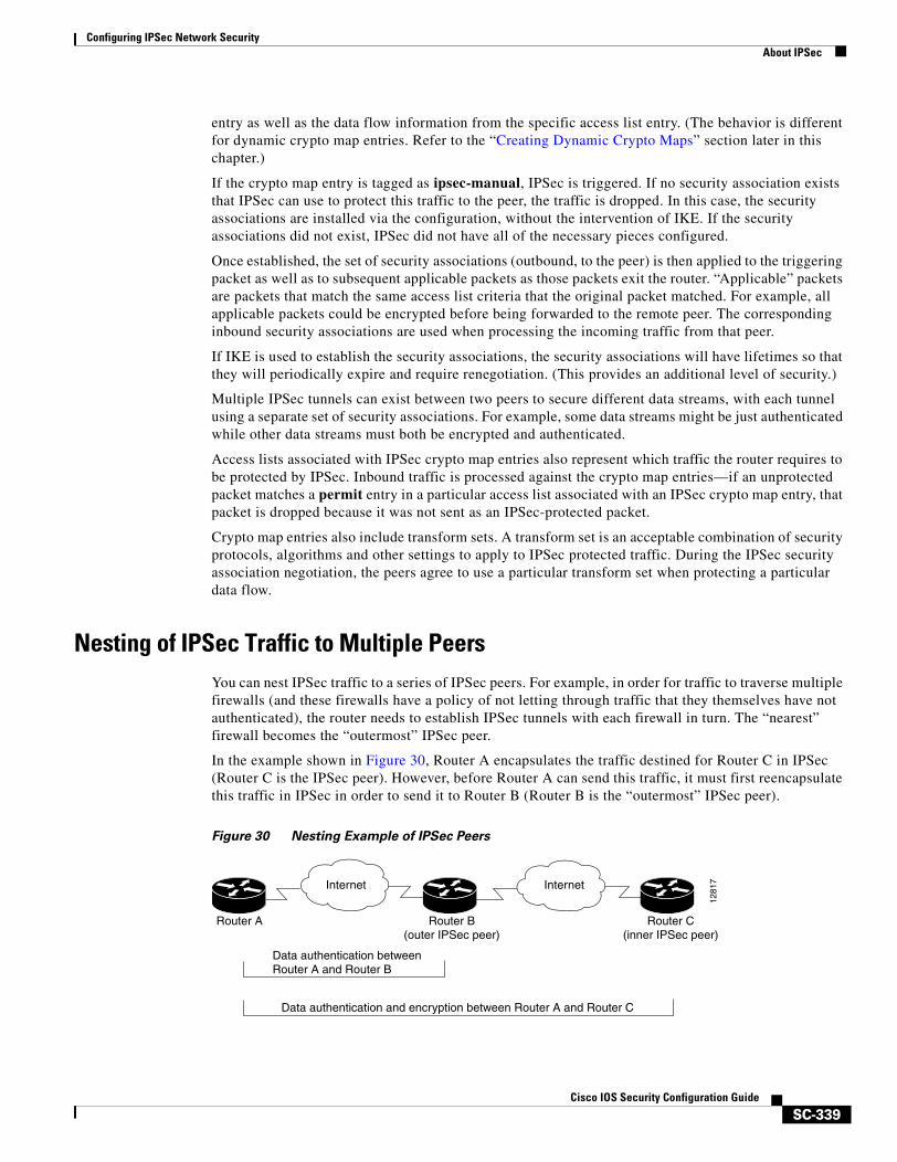
Configuring IPSec Network SecurityAbout IPSec
SC-339Cisco IOS Security Configuration Guide
entry as well as the data flow information from the specific access list entry. (The behavior is different for dynamic crypto map entries. Refer to the “Creating Dynamic Crypto Maps” section later in this chapter.)
If the crypto map entry is tagged as ipsec-manual, IPSec is triggered. If no security association exists that IPSec can use to protect this traffic to the peer, the traffic is dropped. In this case, the security associations are installed via the configuration, without the intervention of IKE. If the security associations did not exist, IPSec did not have all of the necessary pieces configured.
Once established, the set of security associations (outbound, to the peer) is then applied to the triggering packet as well as to subsequent applicable packets as those packets exit the router. “Applicable” packets are packets that match the same access list criteria that the original packet matched. For example, all applicable packets could be encrypted before being forwarded to the remote peer. The corresponding inbound security associations are used when processing the incoming traffic from that peer.
If IKE is used to establish the security associations, the security associations will have lifetimes so that they will periodically expire and require renegotiation. (This provides an additional level of security.)
Multiple IPSec tunnels can exist between two peers to secure different data streams, with each tunnel using a separate set of security associations. For example, some data streams might be just authenticated while other data streams must both be encrypted and authenticated.
Access lists associated with IPSec crypto map entries also represent which traffic the router requires to be protected by IPSec. Inbound traffic is processed against the crypto map entries—if an unprotected packet matches a permit entry in a particular access list associated with an IPSec crypto map entry, that packet is dropped because it was not sent as an IPSec-protected packet.
Crypto map entries also include transform sets. A transform set is an acceptable combination of security protocols, algorithms and other settings to apply to IPSec protected traffic. During the IPSec security association negotiation, the peers agree to use a particular transform set when protecting a particular data flow.
Nesting of IPSec Traffic to Multiple PeersYou can nest IPSec traffic to a series of IPSec peers. For example, in order for traffic to traverse multiple firewalls (and these firewalls have a policy of not letting through traffic that they themselves have not authenticated), the router needs to establish IPSec tunnels with each firewall in turn. The “nearest” firewall becomes the “outermost” IPSec peer.
In the example shown in Figure 30, Router A encapsulates the traffic destined for Router C in IPSec (Router C is the IPSec peer). However, before Router A can send this traffic, it must first reencapsulate this traffic in IPSec in order to send it to Router B (Router B is the “outermost” IPSec peer).
Figure 30 Nesting Example of IPSec Peers
1281
7Internet Internet
Router A
Data authentication betweenRouter A and Router B
Router B(outer IPSec peer)
Router C(inner IPSec peer)
Data authentication and encryption between Router A and Router C
Configuring IPSec Network SecurityIPSec Configuration Task List
SC-340Cisco IOS Security Configuration Guide
It is possible for the traffic between the “outer” peers to have one kind of protection (such as data authentication) and for traffic between the “inner” peers to have different protection (such as both data authentication and encryption).
PrerequisitesYou must configure IKE as described in the “Configuring Internet Key Exchange Security Protocol” chapter.
Even if you decide to not use IKE, you still must disable it as described in the chapter “Configuring Internet Key Exchange Security Protocol.”
IPSec Configuration Task List• Ensuring That Access Lists Are Compatible with IPSec
• Setting Global Lifetimes for IPSec Security Associations
• Creating Crypto Access Lists
• Defining Transform Sets
• Creating Crypto Map Entries
• Applying Crypto Map Sets to Interfaces
• Monitoring and Maintaining IPSec
For IPSec configuration examples, refer to the “IPSec Configuration Example” section at the end of this chapter.
Ensuring That Access Lists Are Compatible with IPSecIKE uses UDP port 500. The IPSec ESP and AH protocols use protocol numbers 50 and 51. Ensure that your access lists are configured so that protocol 50, 51, and UDP port 500 traffic is not blocked at interfaces used by IPSec. In some cases you might need to add a statement to your access lists to explicitly permit this traffic.
Setting Global Lifetimes for IPSec Security AssociationsYou can change the global lifetime values which are used when negotiating new IPSec security associations. (These global lifetime values can be overridden for a particular crypto map entry).
These lifetimes only apply to security associations established via IKE. Manually established security associations do not expire.
There are two lifetimes: a “timed” lifetime and a “traffic-volume” lifetime. A security association expires after the first of these lifetimes is reached. The default lifetimes are 3600 seconds (one hour) and 4,608,000 kilobytes (10 megabytes per second for one hour).
If you change a global lifetime, the new lifetime value will not be applied to currently existing security associations, but will be used in the negotiation of subsequently established security associations. If you wish to use the new values immediately, you can clear all or part of the security association database. Refer to the clear crypto sa command for more details.
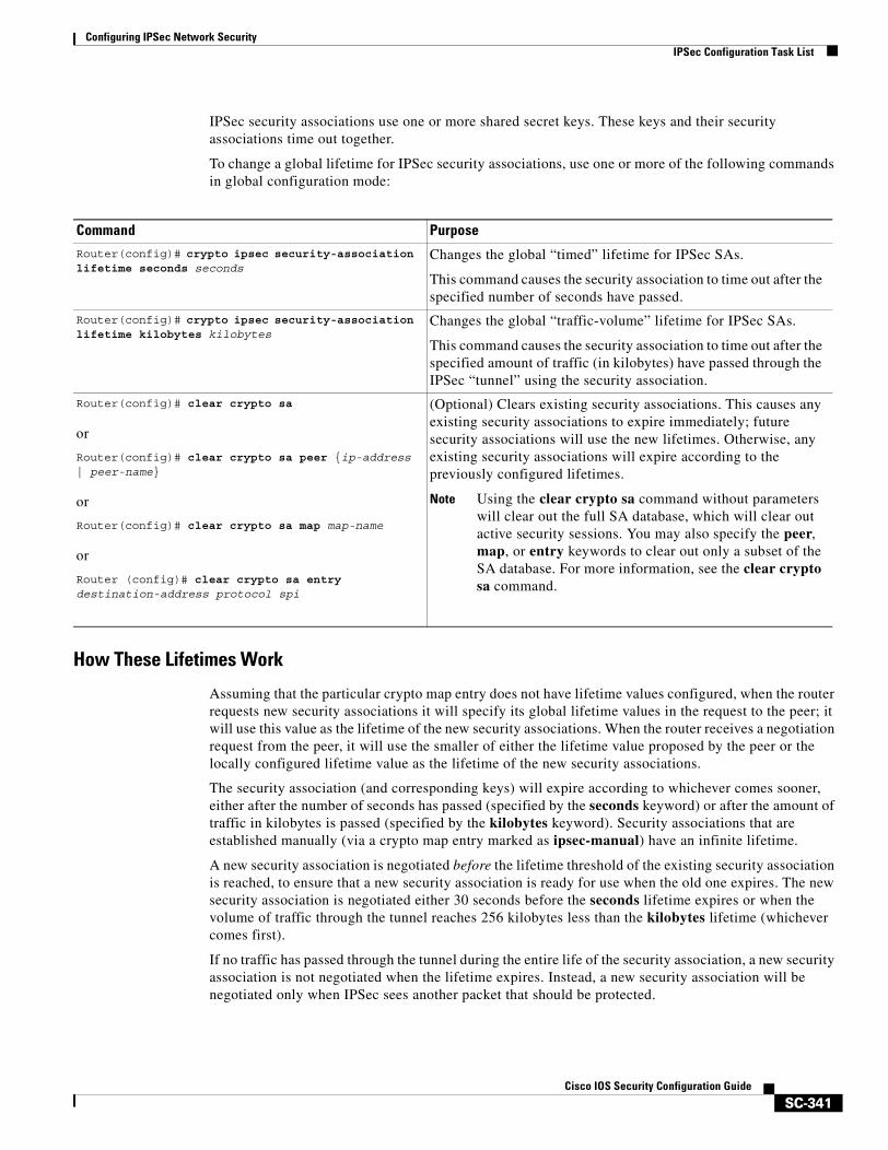
Configuring IPSec Network SecurityIPSec Configuration Task List
SC-341Cisco IOS Security Configuration Guide
IPSec security associations use one or more shared secret keys. These keys and their security associations time out together.
To change a global lifetime for IPSec security associations, use one or more of the following commands in global configuration mode:
How These Lifetimes Work
Assuming that the particular crypto map entry does not have lifetime values configured, when the router requests new security associations it will specify its global lifetime values in the request to the peer; it will use this value as the lifetime of the new security associations. When the router receives a negotiation request from the peer, it will use the smaller of either the lifetime value proposed by the peer or the locally configured lifetime value as the lifetime of the new security associations.
The security association (and corresponding keys) will expire according to whichever comes sooner, either after the number of seconds has passed (specified by the seconds keyword) or after the amount of traffic in kilobytes is passed (specified by the kilobytes keyword). Security associations that are established manually (via a crypto map entry marked as ipsec-manual) have an infinite lifetime.
A new security association is negotiated before the lifetime threshold of the existing security association is reached, to ensure that a new security association is ready for use when the old one expires. The new security association is negotiated either 30 seconds before the seconds lifetime expires or when the volume of traffic through the tunnel reaches 256 kilobytes less than the kilobytes lifetime (whichever comes first).
If no traffic has passed through the tunnel during the entire life of the security association, a new security association is not negotiated when the lifetime expires. Instead, a new security association will be negotiated only when IPSec sees another packet that should be protected.
Command Purpose
Router(config)# crypto ipsec security-association lifetime seconds seconds
Changes the global “timed” lifetime for IPSec SAs.
This command causes the security association to time out after the specified number of seconds have passed.
Router(config)# crypto ipsec security-association lifetime kilobytes kilobytes
Changes the global “traffic-volume” lifetime for IPSec SAs.
This command causes the security association to time out after the specified amount of traffic (in kilobytes) have passed through the IPSec “tunnel” using the security association.
Router(config)# clear crypto sa
or
Router(config)# clear crypto sa peer {ip-address | peer-name}
or
Router(config)# clear crypto sa map map-name
or
Router (config)# clear crypto sa entry destination-address protocol spi
(Optional) Clears existing security associations. This causes any existing security associations to expire immediately; future security associations will use the new lifetimes. Otherwise, any existing security associations will expire according to the previously configured lifetimes.
Note Using the clear crypto sa command without parameters will clear out the full SA database, which will clear out active security sessions. You may also specify the peer, map, or entry keywords to clear out only a subset of the SA database. For more information, see the clear crypto sa command.
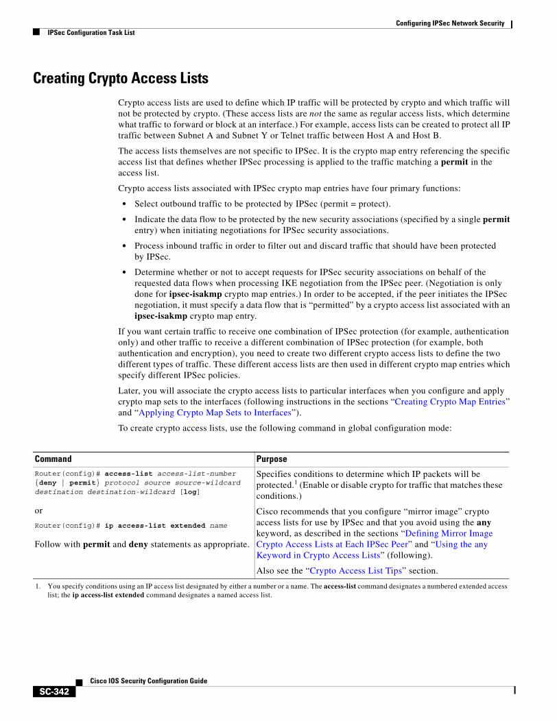
Configuring IPSec Network SecurityIPSec Configuration Task List
SC-342Cisco IOS Security Configuration Guide
Creating Crypto Access ListsCrypto access lists are used to define which IP traffic will be protected by crypto and which traffic will not be protected by crypto. (These access lists are not the same as regular access lists, which determine what traffic to forward or block at an interface.) For example, access lists can be created to protect all IP traffic between Subnet A and Subnet Y or Telnet traffic between Host A and Host B.
The access lists themselves are not specific to IPSec. It is the crypto map entry referencing the specific access list that defines whether IPSec processing is applied to the traffic matching a permit in the access list.
Crypto access lists associated with IPSec crypto map entries have four primary functions:
• Select outbound traffic to be protected by IPSec (permit = protect).
• Indicate the data flow to be protected by the new security associations (specified by a single permit entry) when initiating negotiations for IPSec security associations.
• Process inbound traffic in order to filter out and discard traffic that should have been protected by IPSec.
• Determine whether or not to accept requests for IPSec security associations on behalf of the requested data flows when processing IKE negotiation from the IPSec peer. (Negotiation is only done for ipsec-isakmp crypto map entries.) In order to be accepted, if the peer initiates the IPSec negotiation, it must specify a data flow that is “permitted” by a crypto access list associated with an ipsec-isakmp crypto map entry.
If you want certain traffic to receive one combination of IPSec protection (for example, authentication only) and other traffic to receive a different combination of IPSec protection (for example, both authentication and encryption), you need to create two different crypto access lists to define the two different types of traffic. These different access lists are then used in different crypto map entries which specify different IPSec policies.
Later, you will associate the crypto access lists to particular interfaces when you configure and apply crypto map sets to the interfaces (following instructions in the sections “Creating Crypto Map Entries” and “Applying Crypto Map Sets to Interfaces”).
To create crypto access lists, use the following command in global configuration mode:
Command PurposeRouter(config)# access-list access-list-number {deny | permit} protocol source source-wildcard destination destination-wildcard [log]
or
Router(config)# ip access-list extended name
Follow with permit and deny statements as appropriate.
Specifies conditions to determine which IP packets will be protected.1 (Enable or disable crypto for traffic that matches these conditions.)
Cisco recommends that you configure “mirror image” crypto access lists for use by IPSec and that you avoid using the any keyword, as described in the sections “Defining Mirror Image Crypto Access Lists at Each IPSec Peer” and “Using the any Keyword in Crypto Access Lists” (following).
Also see the “Crypto Access List Tips” section.
1. You specify conditions using an IP access list designated by either a number or a name. The access-list command designates a numbered extended access list; the ip access-list extended command designates a named access list.
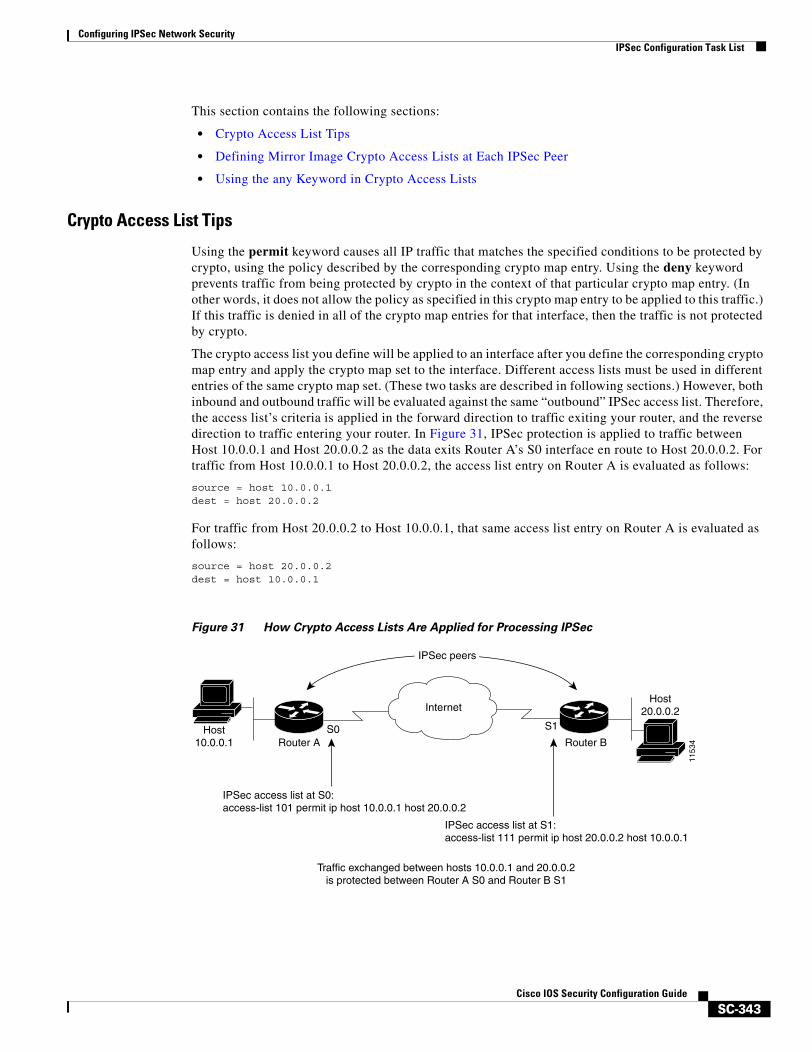
Configuring IPSec Network SecurityIPSec Configuration Task List
SC-343Cisco IOS Security Configuration Guide
This section contains the following sections:
• Crypto Access List Tips
• Defining Mirror Image Crypto Access Lists at Each IPSec Peer
• Using the any Keyword in Crypto Access Lists
Crypto Access List Tips
Using the permit keyword causes all IP traffic that matches the specified conditions to be protected by crypto, using the policy described by the corresponding crypto map entry. Using the deny keyword prevents traffic from being protected by crypto in the context of that particular crypto map entry. (In other words, it does not allow the policy as specified in this crypto map entry to be applied to this traffic.) If this traffic is denied in all of the crypto map entries for that interface, then the traffic is not protected by crypto.
The crypto access list you define will be applied to an interface after you define the corresponding crypto map entry and apply the crypto map set to the interface. Different access lists must be used in different entries of the same crypto map set. (These two tasks are described in following sections.) However, both inbound and outbound traffic will be evaluated against the same “outbound” IPSec access list. Therefore, the access list’s criteria is applied in the forward direction to traffic exiting your router, and the reverse direction to traffic entering your router. In Figure 31, IPSec protection is applied to traffic between Host 10.0.0.1 and Host 20.0.0.2 as the data exits Router A’s S0 interface en route to Host 20.0.0.2. For traffic from Host 10.0.0.1 to Host 20.0.0.2, the access list entry on Router A is evaluated as follows:
source = host 10.0.0.1dest = host 20.0.0.2
For traffic from Host 20.0.0.2 to Host 10.0.0.1, that same access list entry on Router A is evaluated as follows:
source = host 20.0.0.2dest = host 10.0.0.1
Figure 31 How Crypto Access Lists Are Applied for Processing IPSec
IPSec peers
1153
4
Internet
S0 S1
Router A Router BHost
10.0.0.1
Host20.0.0.2
IPSec access list at S0:access-list 101 permit ip host 10.0.0.1 host 20.0.0.2
IPSec access list at S1:access-list 111 permit ip host 20.0.0.2 host 10.0.0.1
Traffic exchanged between hosts 10.0.0.1 and 20.0.0.2is protected between Router A S0 and Router B S1

Configuring IPSec Network SecurityIPSec Configuration Task List
SC-344Cisco IOS Security Configuration Guide
If you configure multiple statements for a given crypto access list which is used for IPSec, in general the first permit statement that is matched will be the statement used to determine the scope of the IPSec security association. That is, the IPSec security association will be set up to protect traffic that meets the criteria of the matched statement only. Later, if traffic matches a different permit statement of the crypto access list, a new, separate IPSec security association will be negotiated to protect traffic matching the newly matched access list statement.
Note Access lists for crypto map entries tagged as ipsec-manual are restricted to a single permit entry and subsequent entries are ignored. In other words, the security associations established by that particular crypto map entry are only for a single data flow. To be able to support multiple manually established security associations for different kinds of traffic, define multiple crypto access lists, and then apply each one to a separate ipsec-manual crypto map entry. Each access list should include one permit statement defining what traffic to protect.
Any unprotected inbound traffic that matches a permit entry in the crypto access list for a crypto map entry flagged as IPSec will be dropped, because this traffic was expected to be protected by IPSec.
Note If you view your router’s access lists by using a command such as show ip access-lists, all extended IP access lists will be shown in the command output. This includes extended IP access lists that are used for traffic filtering purposes as well as those that are used for crypto. The show command output does not differentiate between the different uses of the extended access lists.
See the Cisco IOS Security Command Reference for complete details about the extended IP access list commands used to create IPSec access lists.
Defining Mirror Image Crypto Access Lists at Each IPSec Peer
Cisco recommends that for every crypto access list specified for a static crypto map entry that you define at the local peer, you define a “mirror image” crypto access list at the remote peer. This ensures that traffic that has IPSec protection applied locally can be processed correctly at the remote peer. (The crypto map entries themselves must also support common transforms and must refer to the other system as a peer.)
Figure 32 shows some sample scenarios when you have mirror image access lists and when you do not have mirror image access lists.
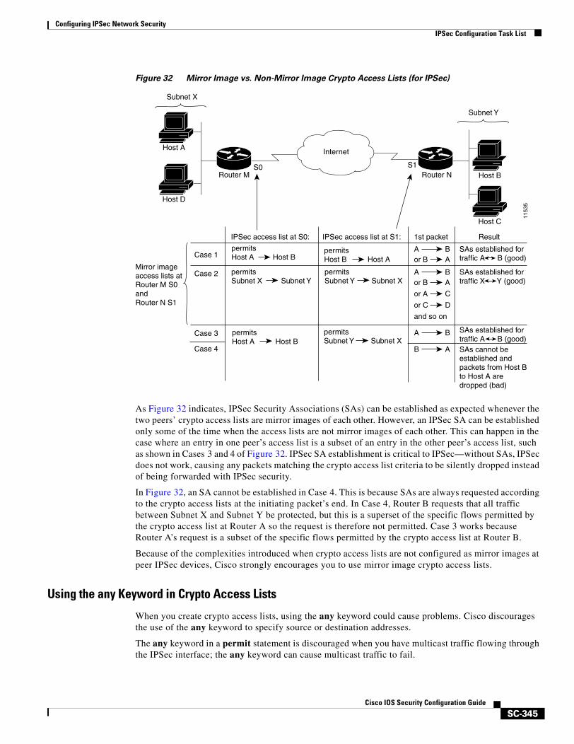
Configuring IPSec Network SecurityIPSec Configuration Task List
SC-345Cisco IOS Security Configuration Guide
Figure 32 Mirror Image vs. Non-Mirror Image Crypto Access Lists (for IPSec)
As Figure 32 indicates, IPSec Security Associations (SAs) can be established as expected whenever the two peers’ crypto access lists are mirror images of each other. However, an IPSec SA can be established only some of the time when the access lists are not mirror images of each other. This can happen in the case where an entry in one peer’s access list is a subset of an entry in the other peer’s access list, such as shown in Cases 3 and 4 of Figure 32. IPSec SA establishment is critical to IPSec—without SAs, IPSec does not work, causing any packets matching the crypto access list criteria to be silently dropped instead of being forwarded with IPSec security.
In Figure 32, an SA cannot be established in Case 4. This is because SAs are always requested according to the crypto access lists at the initiating packet’s end. In Case 4, Router B requests that all traffic between Subnet X and Subnet Y be protected, but this is a superset of the specific flows permitted by the crypto access list at Router A so the request is therefore not permitted. Case 3 works because Router A’s request is a subset of the specific flows permitted by the crypto access list at Router B.
Because of the complexities introduced when crypto access lists are not configured as mirror images at peer IPSec devices, Cisco strongly encourages you to use mirror image crypto access lists.
Using the any Keyword in Crypto Access Lists
When you create crypto access lists, using the any keyword could cause problems. Cisco discourages the use of the any keyword to specify source or destination addresses.
The any keyword in a permit statement is discouraged when you have multicast traffic flowing through the IPSec interface; the any keyword can cause multicast traffic to fail.
1153
5
Internet
S0 S1Router M Router N
Host A
Host D
Host C
Host B
IPSec access list at S0: IPSec access list at S1: 1st packet
Aor B
BA
Result
Aor B
BA
A B
B A
or A C
or C D
and so on
Case 1permitsHost A Host B
permitsHost B Host A
SAs established fortraffic A B (good)
permitsHost A Host B
permitsSubnet X Subnet Y
permitsSubnet Y Subnet X
permitsSubnet Y Subnet X
Case 2
Case 3
Case 4
SAs established fortraffic A B (good)SAs cannot be established and packets from Host B to Host A are dropped (bad)
SAs established fortraffic X Y (good)
Mirror imageaccess lists atRouter M S0and Router N S1
Subnet X
Subnet Y

Configuring IPSec Network SecurityIPSec Configuration Task List
SC-346Cisco IOS Security Configuration Guide
The permit any any statement is strongly discouraged, as this will cause all outbound traffic to be protected (and all protected traffic sent to the peer specified in the corresponding crypto map entry) and will require protection for all inbound traffic. Then, all inbound packets that lack IPSec protection will be silently dropped, including packets for routing protocols, NTP, echo, echo response, and so on.
You need to be sure you define which packets to protect. If you must use the any keyword in a permit statement, you must preface that statement with a series of deny statements to filter out any traffic (that would otherwise fall within that permit statement) that you do not want to be protected.
Defining Transform SetsA transform set represents a certain combination of security protocols and algorithms. During the IPSec security association negotiation, the peers agree to use a particular transform set for protecting a particular data flow.
You can specify multiple transform sets, and then specify one or more of these transform sets in a crypto map entry. The transform set defined in the crypto map entry will be used in the IPSec security association negotiation to protect the data flows specified by that crypto map entry’s access list.
During IPSec security association negotiations with IKE, the peers search for a transform set that is the same at both peers. When such a transform set is found, it is selected and will be applied to the protected traffic as part of both peers’ IPSec security associations.
With manually established security associations, there is no negotiation with the peer, so both sides must specify the same transform set.
If you change a transform set definition, the change is only applied to crypto map entries that reference the transform set. The change will not be applied to existing security associations, but will be used in subsequent negotiations to establish new security associations. If you want the new settings to take effect sooner, you can clear all or part of the security association database by using the clear crypto sa command.
To define a transform set, use the following commands starting in global configuration mode:
Command Purpose
Step 1 Router(config)# crypto ipsec transform-set transform-set-name transform1 [transform2 [transform3]]
Defines a transform set.
There are complex rules defining which entries you can use for the transform arguments. These rules are explained in the command description for the crypto ipsec transform-set command, and Table 24 provides a list of allowed transform combinations.
This command puts you into the crypto transform configuration mode.
Step 2 Router(cfg-crypto-tran)# mode [tunnel | transport] (Optional) Changes the mode associated with the transform set. The mode setting is only applicable to traffic whose source and destination addresses are the IPSec peer addresses; it is ignored for all other traffic. (All other traffic is in tunnel mode only.)
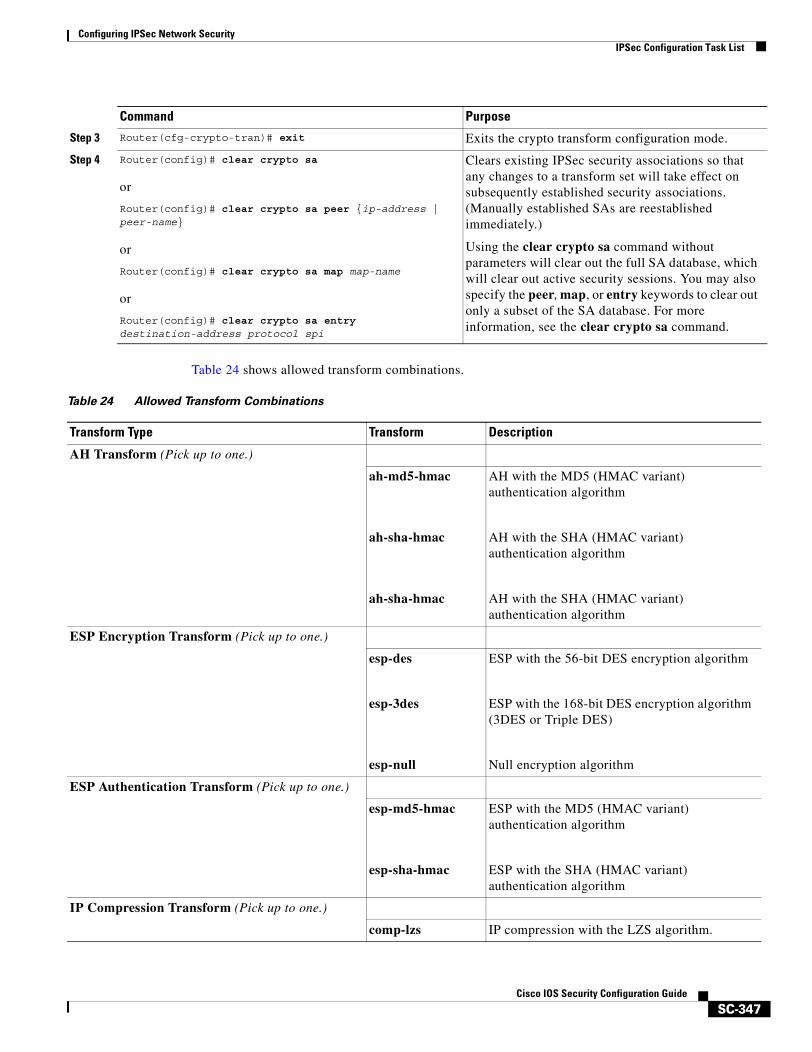
Configuring IPSec Network SecurityIPSec Configuration Task List
SC-347Cisco IOS Security Configuration Guide
Table 24 shows allowed transform combinations.
Step 3 Router(cfg-crypto-tran)# exit Exits the crypto transform configuration mode.
Step 4 Router(config)# clear crypto sa
or
Router(config)# clear crypto sa peer {ip-address | peer-name}
or
Router(config)# clear crypto sa map map-name
or
Router(config)# clear crypto sa entry destination-address protocol spi
Clears existing IPSec security associations so that any changes to a transform set will take effect on subsequently established security associations. (Manually established SAs are reestablished immediately.)
Using the clear crypto sa command without parameters will clear out the full SA database, which will clear out active security sessions. You may also specify the peer, map, or entry keywords to clear out only a subset of the SA database. For more information, see the clear crypto sa command.
Command Purpose
Table 24 Allowed Transform Combinations
Transform Type Transform Description
AH Transform (Pick up to one.)
ah-md5-hmac
ah-sha-hmac
ah-sha-hmac
AH with the MD5 (HMAC variant) authentication algorithm
AH with the SHA (HMAC variant) authentication algorithm
AH with the SHA (HMAC variant) authentication algorithm
ESP Encryption Transform (Pick up to one.)
esp-des
esp-3des
esp-null
ESP with the 56-bit DES encryption algorithm
ESP with the 168-bit DES encryption algorithm (3DES or Triple DES)
Null encryption algorithm
ESP Authentication Transform (Pick up to one.)
esp-md5-hmac
esp-sha-hmac
ESP with the MD5 (HMAC variant) authentication algorithm
ESP with the SHA (HMAC variant) authentication algorithm
IP Compression Transform (Pick up to one.)
comp-lzs IP compression with the LZS algorithm.

Configuring IPSec Network SecurityIPSec Configuration Task List
SC-348Cisco IOS Security Configuration Guide
Creating Crypto Map EntriesTo create crypto map entries, follow the guidelines and tasks described in these sections:
• About Crypto Maps
• Load Sharing
• How Many Crypto Maps Should You Create?
• Creating Crypto Map Entries to Establish Manual Security Associations
• Creating Crypto Map Entries that Use IKE to Establish Security Associations
• Creating Dynamic Crypto Maps
About Crypto Maps
Crypto map entries created for IPSec pull together the various parts used to set up IPSec security associations, including:
• Which traffic should be protected by IPSec (per a crypto access list)
• The granularity of the flow to be protected by a set of security associations
• Where IPSec-protected traffic should be sent (who the remote IPSec peer is)
• The local address to be used for the IPSec traffic (See the “Applying Crypto Map Sets to Interfaces” section for more details.)
• What IPSec security should be applied to this traffic (selecting from a list of one or more transform sets)
• Whether security associations are manually established or are established via IKE
• Other parameters that might be necessary to define an IPSec security association
Crypto map entries with the same crypto map name (but different map sequence numbers) are grouped into a crypto map set. Later, you will apply these crypto map sets to interfaces; then, all IP traffic passing through the interface is evaluated against the applied crypto map set. If a crypto map entry sees outbound IP traffic that should be protected and the crypto map specifies the use of IKE, a security association is negotiated with the remote peer according to the parameters included in the crypto map entry; otherwise, if the crypto map entry specifies the use of manual security associations, a security association should have already been established via configuration. (If a dynamic crypto map entry sees outbound traffic that should be protected and no security association exists, the packet is dropped.)
The policy described in the crypto map entries is used during the negotiation of security associations. If the local router initiates the negotiation, it will use the policy specified in the static crypto map entries to create the offer to be sent to the specified IPSec peer. If the IPSec peer initiates the negotiation, the local router will check the policy from the static crypto map entries, as well as any referenced dynamic crypto map entries to decide whether to accept or reject the peer’s request (offer).
For IPSec to succeed between two IPSec peers, both peers’ crypto map entries must contain compatible configuration statements.
Configuring IPSec Network SecurityIPSec Configuration Task List
SC-349Cisco IOS Security Configuration Guide
When two peers try to establish a security association, they must each have at least one crypto map entry that is compatible with one of the other peer’s crypto map entries. For two crypto map entries to be compatible, they must at least meet the following criteria:
• The crypto map entries must contain compatible crypto access lists (for example, mirror image access lists). In the case where the responding peer is using dynamic crypto maps, the entries in the local crypto access list must be “permitted” by the peer’s crypto access list.
• The crypto map entries must each identify the other peer (unless the responding peer is using dynamic crypto maps).
• The crypto map entries must have at least one transform set in common.
Load Sharing
You can define multiple remote peers using crypto maps to allow for load sharing. If one peer fails, there will still be a protected path. The peer that packets are actually sent to is determined by the last peer that the router heard from (received either traffic or a negotiation request from) for a given data flow. If the attempt fails with the first peer, IKE tries the next peer on the crypto map list.
If you are not sure how to configure each crypto map parameter to guarantee compatibility with other peers, you might consider configuring dynamic crypto maps as described in the “Creating Dynamic Crypto Maps” section. Dynamic crypto maps are useful when the establishment of the IPSec tunnels is initiated by the remote peer (such as in the case of an IPSec router fronting a server). They are not useful if the establishment of the IPSec tunnels is locally initiated, because the dynamic crypto maps are policy templates, not complete statements of policy. (Although the access lists in any referenced dynamic crypto map entry are used for crypto packet filtering.)
How Many Crypto Maps Should You Create?
You can apply only one crypto map set to a single interface. The crypto map set can include a combination of IPSec/IKE and IPSec/manual entries. Multiple interfaces can share the same crypto map set if you want to apply the same policy to multiple interfaces.
If you create more than one crypto map entry for a given interface, use the seq-num of each map entry to rank the map entries: the lower the seq-num, the higher the priority. At the interface that has the crypto map set, traffic is evaluated against higher priority map entries first.
You must create multiple crypto map entries for a given interface if any of the following conditions exist:
• If different data flows are to be handled by separate IPSec peers.
• If you want to apply different IPSec security to different types of traffic (to the same or separate IPSec peers); for example, if you want traffic between one set of subnets to be authenticated, and traffic between another set of subnets to be both authenticated and encrypted. In this case the different types of traffic should have been defined in two separate access lists, and you must create a separate crypto map entry for each crypto access list.
• If you are not using IKE to establish a particular set of security associations, and want to specify multiple access list entries, you must create separate access lists (one per permit entry) and specify a separate crypto map entry for each access list.
Creating Crypto Map Entries to Establish Manual Security Associations
The use of manual security associations is a result of a prior arrangement between the users of the local router and the IPSec peer. The two parties may wish to begin with manual security associations, and then move to using security associations established via IKE, or the remote party’s system may not support
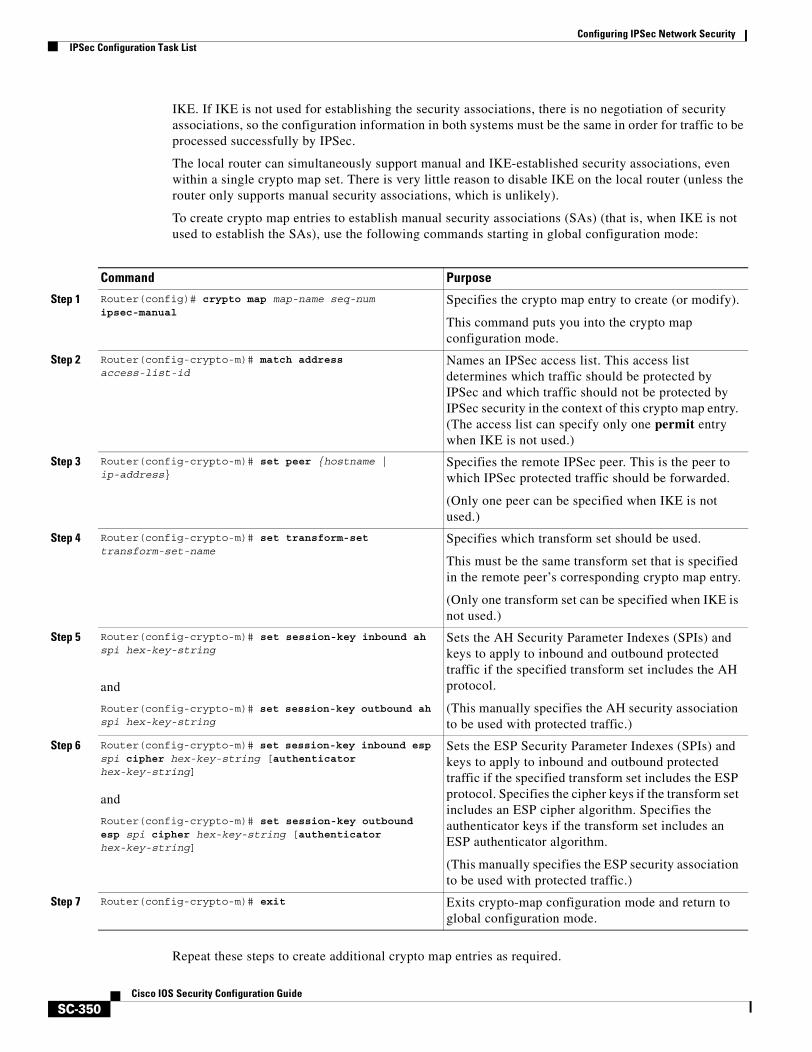
Configuring IPSec Network SecurityIPSec Configuration Task List
SC-350Cisco IOS Security Configuration Guide
IKE. If IKE is not used for establishing the security associations, there is no negotiation of security associations, so the configuration information in both systems must be the same in order for traffic to be processed successfully by IPSec.
The local router can simultaneously support manual and IKE-established security associations, even within a single crypto map set. There is very little reason to disable IKE on the local router (unless the router only supports manual security associations, which is unlikely).
To create crypto map entries to establish manual security associations (SAs) (that is, when IKE is not used to establish the SAs), use the following commands starting in global configuration mode:
Repeat these steps to create additional crypto map entries as required.
Command Purpose
Step 1 Router(config)# crypto map map-name seq-num ipsec-manual
Specifies the crypto map entry to create (or modify).
This command puts you into the crypto map configuration mode.
Step 2 Router(config-crypto-m)# match address access-list-id
Names an IPSec access list. This access list determines which traffic should be protected by IPSec and which traffic should not be protected by IPSec security in the context of this crypto map entry. (The access list can specify only one permit entry when IKE is not used.)
Step 3 Router(config-crypto-m)# set peer {hostname | ip-address}
Specifies the remote IPSec peer. This is the peer to which IPSec protected traffic should be forwarded.
(Only one peer can be specified when IKE is not used.)
Step 4 Router(config-crypto-m)# set transform-set transform-set-name
Specifies which transform set should be used.
This must be the same transform set that is specified in the remote peer’s corresponding crypto map entry.
(Only one transform set can be specified when IKE is not used.)
Step 5 Router(config-crypto-m)# set session-key inbound ah spi hex-key-string
and
Router(config-crypto-m)# set session-key outbound ah spi hex-key-string
Sets the AH Security Parameter Indexes (SPIs) and keys to apply to inbound and outbound protected traffic if the specified transform set includes the AH protocol.
(This manually specifies the AH security association to be used with protected traffic.)
Step 6 Router(config-crypto-m)# set session-key inbound esp spi cipher hex-key-string [authenticator hex-key-string]
and
Router(config-crypto-m)# set session-key outbound esp spi cipher hex-key-string [authenticator hex-key-string]
Sets the ESP Security Parameter Indexes (SPIs) and keys to apply to inbound and outbound protected traffic if the specified transform set includes the ESP protocol. Specifies the cipher keys if the transform set includes an ESP cipher algorithm. Specifies the authenticator keys if the transform set includes an ESP authenticator algorithm.
(This manually specifies the ESP security association to be used with protected traffic.)
Step 7 Router(config-crypto-m)# exit Exits crypto-map configuration mode and return to global configuration mode.
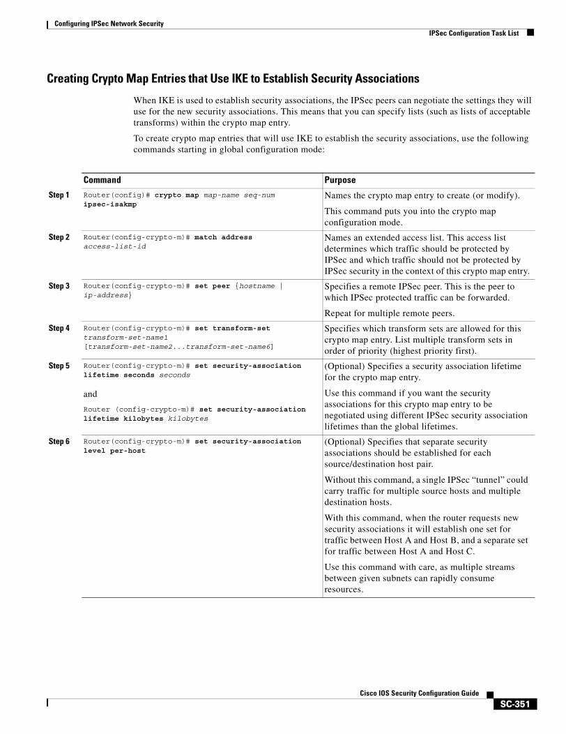
Configuring IPSec Network SecurityIPSec Configuration Task List
SC-351Cisco IOS Security Configuration Guide
Creating Crypto Map Entries that Use IKE to Establish Security Associations
When IKE is used to establish security associations, the IPSec peers can negotiate the settings they will use for the new security associations. This means that you can specify lists (such as lists of acceptable transforms) within the crypto map entry.
To create crypto map entries that will use IKE to establish the security associations, use the following commands starting in global configuration mode:
Command Purpose
Step 1 Router(config)# crypto map map-name seq-num ipsec-isakmp
Names the crypto map entry to create (or modify).
This command puts you into the crypto map configuration mode.
Step 2 Router(config-crypto-m)# match address access-list-id
Names an extended access list. This access list determines which traffic should be protected by IPSec and which traffic should not be protected by IPSec security in the context of this crypto map entry.
Step 3 Router(config-crypto-m)# set peer {hostname | ip-address}
Specifies a remote IPSec peer. This is the peer to which IPSec protected traffic can be forwarded.
Repeat for multiple remote peers.
Step 4 Router(config-crypto-m)# set transform-set transform-set-name1 [transform-set-name2...transform-set-name6]
Specifies which transform sets are allowed for this crypto map entry. List multiple transform sets in order of priority (highest priority first).
Step 5 Router(config-crypto-m)# set security-association lifetime seconds seconds
and
Router (config-crypto-m)# set security-association lifetime kilobytes kilobytes
(Optional) Specifies a security association lifetime for the crypto map entry.
Use this command if you want the security associations for this crypto map entry to be negotiated using different IPSec security association lifetimes than the global lifetimes.
Step 6 Router(config-crypto-m)# set security-association level per-host
(Optional) Specifies that separate security associations should be established for each source/destination host pair.
Without this command, a single IPSec “tunnel” could carry traffic for multiple source hosts and multiple destination hosts.
With this command, when the router requests new security associations it will establish one set for traffic between Host A and Host B, and a separate set for traffic between Host A and Host C.
Use this command with care, as multiple streams between given subnets can rapidly consume resources.

Configuring IPSec Network SecurityIPSec Configuration Task List
SC-352Cisco IOS Security Configuration Guide
Repeat these steps to create additional crypto map entries as required.
Creating Dynamic Crypto Maps
Dynamic crypto maps (this requires IKE) can ease IPSec configuration and are recommended for use with networks where the peers are not always predetermined. An example of this is mobile users, who obtain dynamically-assigned IP addresses. First, the mobile clients need to authenticate themselves to the local router’s IKE by something other than an IP address, such as a fully qualified domain name. Once authenticated, the security association request can be processed against a dynamic crypto map which is set up to accept requests (matching the specified local policy) from previously unknown peers.
To configure dynamic crypto maps, follow the instructions in these sections:
• Understanding Dynamic Crypto Maps
• Creating a Dynamic Crypto Map Set
• Adding the Dynamic Crypto Map Set into a Regular (Static) Crypto Map Set
Understanding Dynamic Crypto Maps
Dynamic crypto maps are only available for use by IKE.
A dynamic crypto map entry is essentially a crypto map entry without all the parameters configured. It acts as a policy template where the missing parameters are later dynamically configured (as the result of an IPSec negotiation) to match a remote peer’s requirements. This allows remote peers to exchange IPSec traffic with the router even if the router does not have a crypto map entry specifically configured to meet all of the remote peer’s requirements.
Dynamic crypto maps are not used by the router to initiate new IPSec security associations with remote peers. Dynamic crypto maps are used when a remote peer tries to initiate an IPSec security association with the router. Dynamic crypto maps are also used in evaluating traffic.
A dynamic crypto map set is included by reference as part of a crypto map set. Any crypto map entries that reference dynamic crypto map sets should be the lowest priority crypto map entries in the crypto map set (that is, have the highest sequence numbers) so that the other crypto map entries are evaluated first; that way, the dynamic crypto map set is examined only when the other (static) map entries are not successfully matched.
If the router accepts the peer’s request, at the point that it installs the new IPSec security associations it also installs a temporary crypto map entry. This entry is filled in with the results of the negotiation. At this point, the router performs normal processing, using this temporary crypto map entry as a normal entry, even requesting new security associations if the current ones are expiring (based upon the policy specified in the temporary crypto map entry). Once the flow expires (that is, all of the corresponding security associations expire), the temporary crypto map entry is then removed.
Step 7 Router(config-crypto-m)# set pfs [group1 | group2] (Optional) Specifies that IPSec should ask for perfect forward secrecy when requesting new security associations for this crypto map entry, or should demand PFS in requests received from the IPSec peer.
Step 8 Router(config-crypto-m)# exit Exits crypto-map configuration mode and return to global configuration mode.
Command Purpose
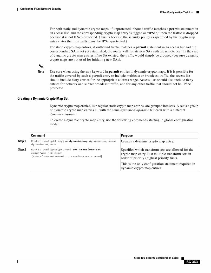
Configuring IPSec Network SecurityIPSec Configuration Task List
SC-353Cisco IOS Security Configuration Guide
For both static and dynamic crypto maps, if unprotected inbound traffic matches a permit statement in an access list, and the corresponding crypto map entry is tagged as “IPSec,” then the traffic is dropped because it is not IPSec-protected. (This is because the security policy as specified by the crypto map entry states that this traffic must be IPSec-protected.)
For static crypto map entries, if outbound traffic matches a permit statement in an access list and the corresponding SA is not yet established, the router will initiate new SAs with the remote peer. In the case of dynamic crypto map entries, if no SA existed, the traffic would simply be dropped (because dynamic crypto maps are not used for initiating new SAs).
Note Use care when using the any keyword in permit entries in dynamic crypto maps. If it is possible for the traffic covered by such a permit entry to include multicast or broadcast traffic, the access list should include deny entries for the appropriate address range. Access lists should also include deny entries for network and subnet broadcast traffic, and for any other traffic that should not be IPSec protected.
Creating a Dynamic Crypto Map Set
Dynamic crypto map entries, like regular static crypto map entries, are grouped into sets. A set is a group of dynamic crypto map entries all with the same dynamic-map-name but each with a different dynamic-seq-num.
To create a dynamic crypto map entry, use the following commands starting in global configuration mode:
Command Purpose
Step 1 Router(config)# crypto dynamic-map dynamic-map-name dynamic-seq-num
Creates a dynamic crypto map entry.
Step 2 Router(config-crypto-m)# set transform-set transform-set-name1 [transform-set-name2...transform-set-name6]
Specifies which transform sets are allowed for the crypto map entry. List multiple transform sets in order of priority (highest priority first).
This is the only configuration statement required in dynamic crypto map entries.
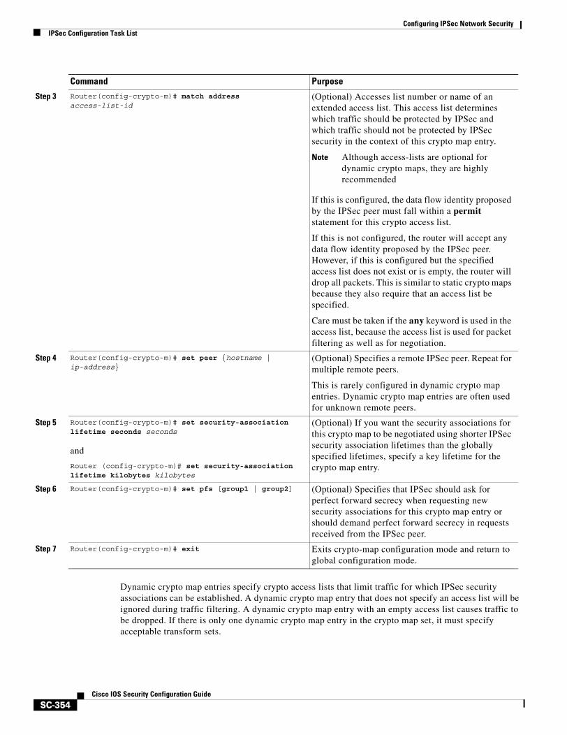
Configuring IPSec Network SecurityIPSec Configuration Task List
SC-354Cisco IOS Security Configuration Guide
Dynamic crypto map entries specify crypto access lists that limit traffic for which IPSec security associations can be established. A dynamic crypto map entry that does not specify an access list will be ignored during traffic filtering. A dynamic crypto map entry with an empty access list causes traffic to be dropped. If there is only one dynamic crypto map entry in the crypto map set, it must specify acceptable transform sets.
Step 3 Router(config-crypto-m)# match address access-list-id
(Optional) Accesses list number or name of an extended access list. This access list determines which traffic should be protected by IPSec and which traffic should not be protected by IPSec security in the context of this crypto map entry.
Note Although access-lists are optional for dynamic crypto maps, they are highly recommended
If this is configured, the data flow identity proposed by the IPSec peer must fall within a permit statement for this crypto access list.
If this is not configured, the router will accept any data flow identity proposed by the IPSec peer. However, if this is configured but the specified access list does not exist or is empty, the router will drop all packets. This is similar to static crypto maps because they also require that an access list be specified.
Care must be taken if the any keyword is used in the access list, because the access list is used for packet filtering as well as for negotiation.
Step 4 Router(config-crypto-m)# set peer {hostname | ip-address}
(Optional) Specifies a remote IPSec peer. Repeat for multiple remote peers.
This is rarely configured in dynamic crypto map entries. Dynamic crypto map entries are often used for unknown remote peers.
Step 5 Router(config-crypto-m)# set security-association lifetime seconds seconds
and
Router (config-crypto-m)# set security-association lifetime kilobytes kilobytes
(Optional) If you want the security associations for this crypto map to be negotiated using shorter IPSec security association lifetimes than the globally specified lifetimes, specify a key lifetime for the crypto map entry.
Step 6 Router(config-crypto-m)# set pfs [group1 | group2] (Optional) Specifies that IPSec should ask for perfect forward secrecy when requesting new security associations for this crypto map entry or should demand perfect forward secrecy in requests received from the IPSec peer.
Step 7 Router(config-crypto-m)# exit Exits crypto-map configuration mode and return to global configuration mode.
Command Purpose
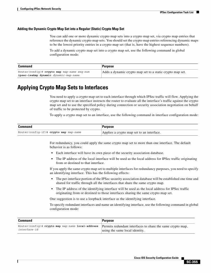
Configuring IPSec Network SecurityIPSec Configuration Task List
SC-355Cisco IOS Security Configuration Guide
Adding the Dynamic Crypto Map Set into a Regular (Static) Crypto Map Set
You can add one or more dynamic crypto map sets into a crypto map set, via crypto map entries that reference the dynamic crypto map sets. You should set the crypto map entries referencing dynamic maps to be the lowest priority entries in a crypto map set (that is, have the highest sequence numbers).
To add a dynamic crypto map set into a crypto map set, use the following command in global configuration mode:
Applying Crypto Map Sets to InterfacesYou need to apply a crypto map set to each interface through which IPSec traffic will flow. Applying the crypto map set to an interface instructs the router to evaluate all the interface’s traffic against the crypto map set and to use the specified policy during connection or security association negotiation on behalf of traffic to be protected by crypto.
To apply a crypto map set to an interface, use the following command in interface configuration mode:
For redundancy, you could apply the same crypto map set to more than one interface. The default behavior is as follows:
• Each interface will have its own piece of the security association database.
• The IP address of the local interface will be used as the local address for IPSec traffic originating from or destined to that interface.
If you apply the same crypto map set to multiple interfaces for redundancy purposes, you need to specify an identifying interface. This has the following effects:
• The per-interface portion of the IPSec security association database will be established one time and shared for traffic through all the interfaces that share the same crypto map.
• The IP address of the identifying interface will be used as the local address for IPSec traffic originating from or destined to those interfaces sharing the same crypto map set.
One suggestion is to use a loopback interface as the identifying interface.
To specify redundant interfaces and name an identifying interface, use the following command in global configuration mode:
Command PurposeRouter(config)# crypto map map-name seq-num ipsec-isakmp dynamic dynamic-map-name
Adds a dynamic crypto map set to a static crypto map set.
Command PurposeRouter(config-if)# crypto map map-name Applies a crypto map set to an interface.
Command PurposeRouter(config)# crypto map map-name local-address interface-id
Permits redundant interfaces to share the same crypto map, using the same local identity.
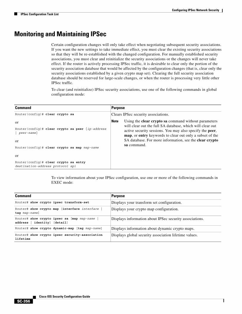
Configuring IPSec Network SecurityIPSec Configuration Task List
SC-356Cisco IOS Security Configuration Guide
Monitoring and Maintaining IPSecCertain configuration changes will only take effect when negotiating subsequent security associations. If you want the new settings to take immediate effect, you must clear the existing security associations so that they will be re-established with the changed configuration. For manually established security associations, you must clear and reinitialize the security associations or the changes will never take effect. If the router is actively processing IPSec traffic, it is desirable to clear only the portion of the security association database that would be affected by the configuration changes (that is, clear only the security associations established by a given crypto map set). Clearing the full security association database should be reserved for large-scale changes, or when the router is processing very little other IPSec traffic.
To clear (and reinitialize) IPSec security associations, use one of the following commands in global configuration mode:
To view information about your IPSec configuration, use one or more of the following commands in EXEC mode:
Command Purpose
Router(config)# clear crypto sa
or
Router(config)# clear crypto sa peer {ip-address | peer-name}
or
Router(config)# clear crypto sa map map-name
or
Router(config)# clear crypto sa entry destination-address protocol spi
Clears IPSec security associations.
Note Using the clear crypto sa command without parameters will clear out the full SA database, which will clear out active security sessions. You may also specify the peer, map, or entry keywords to clear out only a subset of the SA database. For more information, see the clear crypto sa command.
Command Purpose
Router# show crypto ipsec transform-set Displays your transform set configuration.
Router# show crypto map [interface interface | tag map-name]
Displays your crypto map configuration.
Router# show crypto ipsec sa [map map-name | address | identity] [detail]
Displays information about IPSec security associations.
Router# show crypto dynamic-map [tag map-name] Displays information about dynamic crypto maps.
Router# show crypto ipsec security-association lifetime
Displays global security association lifetime values.
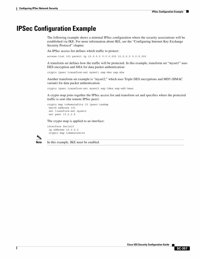
Configuring IPSec Network SecurityIPSec Configuration Example
SC-357Cisco IOS Security Configuration Guide
IPSec Configuration ExampleThe following example shows a minimal IPSec configuration where the security associations will be established via IKE. For more information about IKE, see the “Configuring Internet Key Exchange Security Protocol” chapter.
An IPSec access list defines which traffic to protect:
access-list 101 permit ip 10.0.0.0 0.0.0.255 10.2.2.0 0.0.0.255
A transform set defines how the traffic will be protected. In this example, transform set “myset1” uses DES encryption and SHA for data packet authentication:
crypto ipsec transform-set myset1 esp-des esp-sha
Another transform set example is “myset2,” which uses Triple DES encryptions and MD5 (HMAC variant) for data packet authentication:
crypto ipsec transform-set myset2 esp-3des esp-md5-hmac
A crypto map joins together the IPSec access list and transform set and specifies where the protected traffic is sent (the remote IPSec peer):
crypto map toRemoteSite 10 ipsec-isakmpmatch address 101set transform-set myset2set peer 10.2.2.5
The crypto map is applied to an interface:
interface Serial0ip address 10.0.0.2crypto map toRemoteSite
Note In this example, IKE must be enabled.

Configuring IPSec Network SecurityIPSec Configuration Example
SC-358Cisco IOS Security Configuration Guide
SC-359Cisco IOS Security Configuration Guide
Configuring Certification Authority Interoperability
This chapter describes how to configure certification authority (CA) interoperability, which is provided in support of the IP Security (IPSec) protocol. CA interoperability permits Cisco IOS devices and CAs to communicate so that your Cisco IOS device can obtain and use digital certificates from the CA. Although IPSec can be implemented in your network without the use of a CA, using a CA provides manageability and scalability for IPSec.
For background and configuration information for IPSec, see the chapter “Configuring IPSec Network Security.”
For a complete description of the commands used in this chapter, refer to the chapter “Certification Authority Interoperability Commands” in the Cisco IOS Security Command Reference. To locate documentation for other commands that appear in this chapter, use the command reference master index or search online.
To identify the hardware platform or software image information associated with a feature, use the Feature Navigator on Cisco.com to search for information about the feature or refer to the software release notes for a specific release. For more information, see the “Identifying Supported Platforms” section in the chapter “Using Cisco IOS Software.”
In This ChapterThis chapter contains the following sections:
• About CA Interoperability
• About Certification Authorities
• CA Interoperability Configuration Task Lists
• What to Do Next
• CA Interoperability Configuration Examples
Configuring Certification Authority InteroperabilityAbout CA Interoperability
SC-360Cisco IOS Security Configuration Guide
About CA Interoperability Without CA interoperability, Cisco IOS devices could not use CAs when deploying IPSec. CAs provide a manageable, scalable solution for IPSec networks. For details, see the section “About Certification Authorities.”
This section contains the following sections:
• Supported Standards
• Restrictions
• Prerequisites
Supported StandardsCisco supports the following standards with this feature:
• IPSec—IP Security Protocol. IPSec is a framework of open standards that provides data confidentiality, data integrity, and data authentication between participating peers. IPSec provides these security services at the IP layer; it uses Internet Key Exchange to handle negotiation of protocols and algorithms based on local policy, and to generate the encryption and authentication keys to be used by IPSec. IPSec can be used to protect one or more data flows between a pair of hosts, between a pair of security gateways, or between a security gateway and a host.
For more information on IPSec, see the chapter “Configuring IPSec Network Security.”
• Internet Key Exchange (IKE)—A hybrid protocol that implements Oakley and Skeme key exchanges inside the Internet Security Association Key Management Protocol (ISAKMP) framework. Although IKE can be used with other protocols, its initial implementation is with the IPSec protocol. IKE provides authentication of the IPSec peers, negotiates IPSec keys, and negotiates IPSec security associations.
For more information on IKE, see the chapter “Configuring Internet Key Exchange Security Protocol.”
• Public-Key Cryptography Standard #7 (PKCS #7)—A standard from RSA Data Security, Inc., used to encrypt and sign certificate enrollment messages.
• Public-Key Cryptography Standard #10 (PKCS #10)—A standard syntax from RSA Data Security, Inc. for certificate requests.
• RSA Keys—RSA is the public key cryptographic system developed by Ron Rivest, Adi Shamir, and Leonard Adleman. RSA keys come in pairs: one public key and one private key.
• X.509v3 certificates—Certificate support that allows the IPSec-protected network to scale by providing the equivalent of a digital ID card to each device. When two devices wish to communicate, they exchange digital certificates to prove their identity (thus removing the need to manually exchange public keys with each peer or to manually specify a shared key at each peer). These certificates are obtained from a certification authority (CA). X.509 is part of the X.500 standard of the ITU.
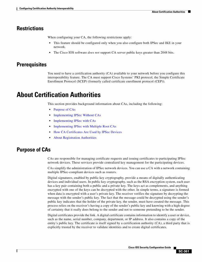
Configuring Certification Authority InteroperabilityAbout Certification Authorities
SC-361Cisco IOS Security Configuration Guide
RestrictionsWhen configuring your CA, the following restrictions apply:
• This feature should be configured only when you also configure both IPSec and IKE in your network.
• The Cisco IOS software does not support CA server public keys greater than 2048 bits.
PrerequisitesYou need to have a certification authority (CA) available to your network before you configure this interoperability feature. The CA must support Cisco Systems’ PKI protocol, the Simple Certificate Enrollment Protocol (SCEP) (formerly called certificate enrollment protocol (CEP)).
About Certification AuthoritiesThis section provides background information about CAs, including the following:
• Purpose of CAs
• Implementing IPSec Without CAs
• Implementing IPSec with CAs
• Implementing IPSec with Multiple Root CAs
• How CA Certificates Are Used by IPSec Devices
• About Registration Authorities
Purpose of CAsCAs are responsible for managing certificate requests and issuing certificates to participating IPSec network devices. These services provide centralized key management for the participating devices.
CAs simplify the administration of IPSec network devices. You can use a CA with a network containing multiple IPSec-compliant devices such as routers.
Digital signatures, enabled by public key cryptography, provide a means of digitally authenticating devices and individual users. In public key cryptography, such as the RSA encryption system, each user has a key pair containing both a public and a private key. The keys act as complements, and anything encrypted with one of the keys can be decrypted with the other. In simple terms, a signature is formed when data is encrypted with a user’s private key. The receiver verifies the signature by decrypting the message with the sender’s public key. The fact that the message could be decrypted using the sender’s public key indicates that the holder of the private key, the sender, must have created the message. This process relies on the receiver’s having a copy of the sender’s public key and knowing with a high degree of certainty that it really does belong to the sender and not to someone pretending to be the sender.
Digital certificates provide the link. A digital certificate contains information to identify a user or device, such as the name, serial number, company, department, or IP address. It also contains a copy of the entity’s public key. The certificate is itself signed by a certification authority (CA), a third party that is explicitly trusted by the receiver to validate identities and to create digital certificates.
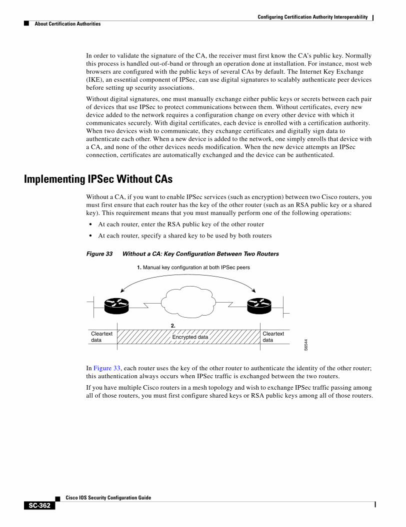
Configuring Certification Authority InteroperabilityAbout Certification Authorities
SC-362Cisco IOS Security Configuration Guide
In order to validate the signature of the CA, the receiver must first know the CA’s public key. Normally this process is handled out-of-band or through an operation done at installation. For instance, most web browsers are configured with the public keys of several CAs by default. The Internet Key Exchange (IKE), an essential component of IPSec, can use digital signatures to scalably authenticate peer devices before setting up security associations.
Without digital signatures, one must manually exchange either public keys or secrets between each pair of devices that use IPSec to protect communications between them. Without certificates, every new device added to the network requires a configuration change on every other device with which it communicates securely. With digital certificates, each device is enrolled with a certification authority. When two devices wish to communicate, they exchange certificates and digitally sign data to authenticate each other. When a new device is added to the network, one simply enrolls that device with a CA, and none of the other devices needs modification. When the new device attempts an IPSec connection, certificates are automatically exchanged and the device can be authenticated.
Implementing IPSec Without CAsWithout a CA, if you want to enable IPSec services (such as encryption) between two Cisco routers, you must first ensure that each router has the key of the other router (such as an RSA public key or a shared key). This requirement means that you must manually perform one of the following operations:
• At each router, enter the RSA public key of the other router
• At each router, specify a shared key to be used by both routers
Figure 33 Without a CA: Key Configuration Between Two Routers
In Figure 33, each router uses the key of the other router to authenticate the identity of the other router; this authentication always occurs when IPSec traffic is exchanged between the two routers.
If you have multiple Cisco routers in a mesh topology and wish to exchange IPSec traffic passing among all of those routers, you must first configure shared keys or RSA public keys among all of those routers.
1. Manual key configuration at both IPSec peers
2.
S65
44
Cleartextdata
CleartextdataEncrypted data
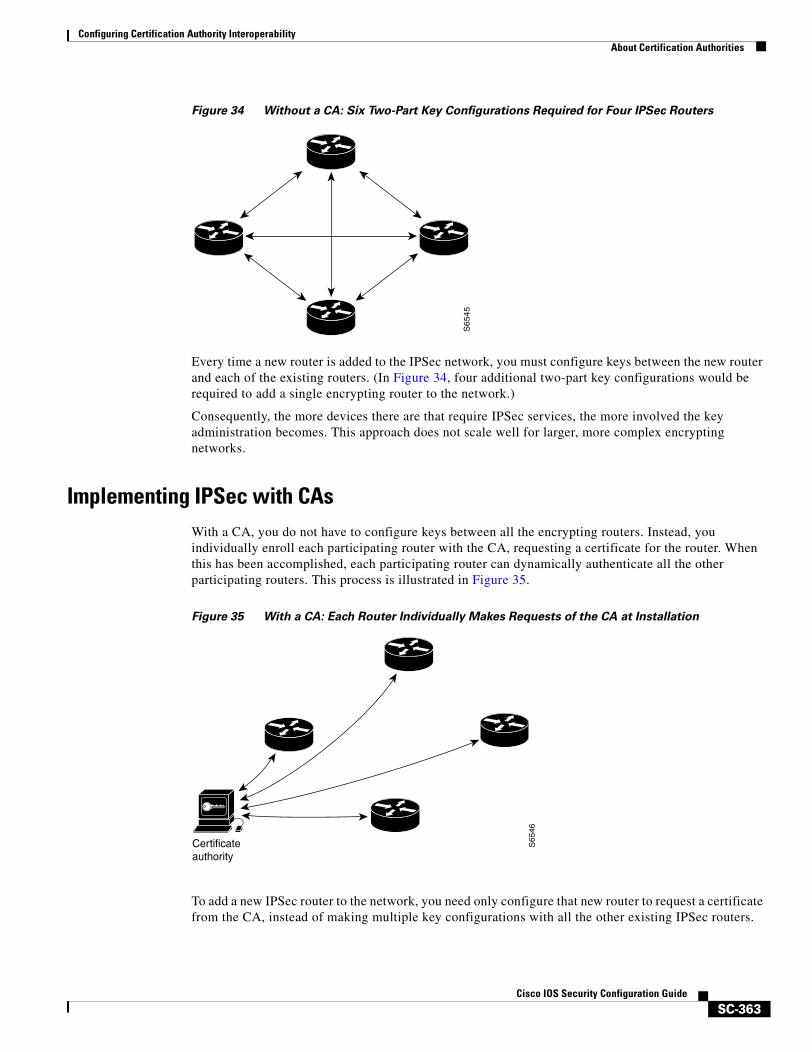
Configuring Certification Authority InteroperabilityAbout Certification Authorities
SC-363Cisco IOS Security Configuration Guide
Figure 34 Without a CA: Six Two-Part Key Configurations Required for Four IPSec Routers
Every time a new router is added to the IPSec network, you must configure keys between the new router and each of the existing routers. (In Figure 34, four additional two-part key configurations would be required to add a single encrypting router to the network.)
Consequently, the more devices there are that require IPSec services, the more involved the key administration becomes. This approach does not scale well for larger, more complex encrypting networks.
Implementing IPSec with CAsWith a CA, you do not have to configure keys between all the encrypting routers. Instead, you individually enroll each participating router with the CA, requesting a certificate for the router. When this has been accomplished, each participating router can dynamically authenticate all the other participating routers. This process is illustrated in Figure 35.
Figure 35 With a CA: Each Router Individually Makes Requests of the CA at Installation
To add a new IPSec router to the network, you need only configure that new router to request a certificate from the CA, instead of making multiple key configurations with all the other existing IPSec routers.
S6
54
5
S65
46
Certificateauthority
Configuring Certification Authority InteroperabilityAbout Certification Authorities
SC-364Cisco IOS Security Configuration Guide
Implementing IPSec with Multiple Root CAsWith multiple root CAs, you no longer have to enroll a router with the CA that issued a certificate to a peer. Instead, you configure a router with multiple CAs that it trusts. Thus, a router can use a configured CA (a trusted root) to verify certificates offered by a peer that were not issued by the same CA defined in the identity of the router.
Configuring multiple CAs allows two or more routers enrolled under different domains (different CAs) to verify the identity of each other when using IKE to set up IPSec tunnels.
Through Simple Certificate Enrollment Protocol (SCEP), each router is configured with a CA (the enrollment CA). The CA issues a certificate to the router that is signed with the private key of the CA. To verify the certificates of peers in the same domain, the router is also configured with the root certificate of the enrollment CA.
To verify the certificate of a peer from a different domain, the root certificate of the enrollment CA in the domain of the peer must be configured securely in the router.
During IKE phase one signature verification, the initiator will send the responder a list of its CA certificates. The responder should send the certificate issued by one of the CAs in the list. If the certificate is verified, the router saves the public key contained in the certificate on its public key ring.
With multiple root CAs, Virtual Private Network (VPN) users can establish trust in one domain and easily and securely distribute it to other domains. Thus, the required private communication channel between entities authenticated under different domains can occur.
How CA Certificates Are Used by IPSec DevicesWhen two IPSec routers want to exchange IPSec-protected traffic passing between them, they must first authenticate each other—otherwise, IPSec protection cannot occur. The authentication is done with IKE.
Without a CA, a router authenticates itself to the remote router using either RSA-encrypted nonces or preshared keys. Both methods require that keys must have been previously configured between the two routers.
With a CA, a router authenticates itself to the remote router by sending a certificate to the remote router and performing some public key cryptography. Each router must send its own unique certificate that was issued and validated by the CA. This process works because the certificate of each router encapsulates the public key of the router, each certificate is authenticated by the CA, and all participating routers recognize the CA as an authenticating authority. This scheme is called IKE with an RSA signature.
Your router can continue sending its own certificate for multiple IPSec sessions, and to multiple IPSec peers until the certificate expires. When its certificate expires, the router administrator must obtain a new one from the CA.
CAs can also revoke certificates for devices that will no longer participate in IPSec. Revoked certificates are not recognized as valid by other IPSec devices. Revoked certificates are listed in a certificate revocation list (CRL), which each peer may check before accepting a certificate from another peer.
About Registration AuthoritiesSome CAs have a registration authority (RA) as part of their implementation. An RA is essentially a server that acts as a proxy for the CA so that CA functions can continue when the CA is offline.
Some of the configuration tasks described in this document differ slightly, depending on whether your CA supports an RA.
Configuring Certification Authority InteroperabilityCA Interoperability Configuration Task Lists
SC-365Cisco IOS Security Configuration Guide
CA Interoperability Configuration Task ListsTo enable your Cisco device to interoperate with a CA, complete the tasks in the following sections. Some of the tasks are optional; the remaining are required.
• Managing NVRAM Memory Usage (Optional)
• Configuring the Routers Host Name and IP Domain Name (Required)
• Generating an RSA Key Pair (Required)
• Declaring a Certification Authority (Required)
• Configuring a Root CA (Trusted Root) (Optional)
• Authenticating the CA (Required)
• Requesting Your Own Certificates (Required)
• Saving Your Configuration (Required)
• Monitoring and Maintaining Certification Authority Interoperability (Optional)
For CA interoperability configuration examples, refer to the section “CA Interoperability Configuration Examples” at the end of this chapter.
Managing NVRAM Memory UsageCertificates and certificate revocation lists (CRLs) are used by your router when a CA is used. Normally certain certificates and all CRLs are stored locally in the router’s NVRAM, and each certificate and CRL uses a moderate amount of memory.
The following certificates are normally stored at your router:
• The certificate of your router
• The certificate of the CA
• Root certificates obtained from CA servers (all root certificates are saved in RAM after the router has been initialized)
• Two registration authority (RA) certificates (only if the CA supports an RA)
CRLs are normally stored at your router according to the following conditions:
• If your CA does not support an RA, only one CRL gets stored at your router.
• If your CA supports an RA, multiple CRLs can be stored at your router.
In some cases, storing these certificates and CRLs locally will not present any difficulty. In other cases, memory might become a problem—particularly if your CA supports an RA and a large number of CRLs have to be stored on your router. If the NVRAM is too small to store root certificates, only the fingerprint of the root certificate will be saved.
To save NVRAM space, you can specify that certificates and CRLs should not be stored locally, but should be retrieved from the CA when needed. This alternative will save NVRAM space but could result in a slight performance impact.
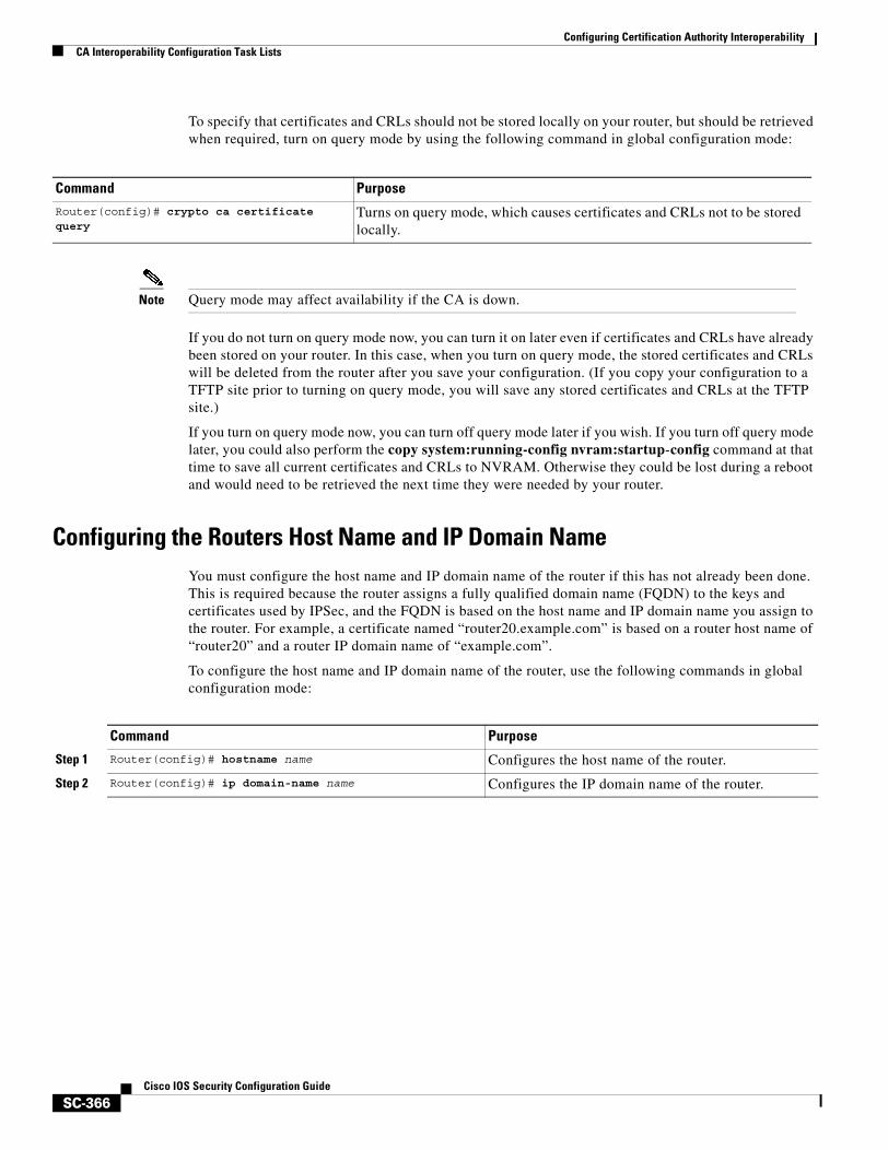
Configuring Certification Authority InteroperabilityCA Interoperability Configuration Task Lists
SC-366Cisco IOS Security Configuration Guide
To specify that certificates and CRLs should not be stored locally on your router, but should be retrieved when required, turn on query mode by using the following command in global configuration mode:
Note Query mode may affect availability if the CA is down.
If you do not turn on query mode now, you can turn it on later even if certificates and CRLs have already been stored on your router. In this case, when you turn on query mode, the stored certificates and CRLs will be deleted from the router after you save your configuration. (If you copy your configuration to a TFTP site prior to turning on query mode, you will save any stored certificates and CRLs at the TFTP site.)
If you turn on query mode now, you can turn off query mode later if you wish. If you turn off query mode later, you could also perform the copy system:running-config nvram:startup-config command at that time to save all current certificates and CRLs to NVRAM. Otherwise they could be lost during a reboot and would need to be retrieved the next time they were needed by your router.
Configuring the Routers Host Name and IP Domain NameYou must configure the host name and IP domain name of the router if this has not already been done. This is required because the router assigns a fully qualified domain name (FQDN) to the keys and certificates used by IPSec, and the FQDN is based on the host name and IP domain name you assign to the router. For example, a certificate named “router20.example.com” is based on a router host name of “router20” and a router IP domain name of “example.com”.
To configure the host name and IP domain name of the router, use the following commands in global configuration mode:
Command PurposeRouter(config)# crypto ca certificate query
Turns on query mode, which causes certificates and CRLs not to be stored locally.
Command Purpose
Step 1 Router(config)# hostname name Configures the host name of the router.
Step 2 Router(config)# ip domain-name name Configures the IP domain name of the router.
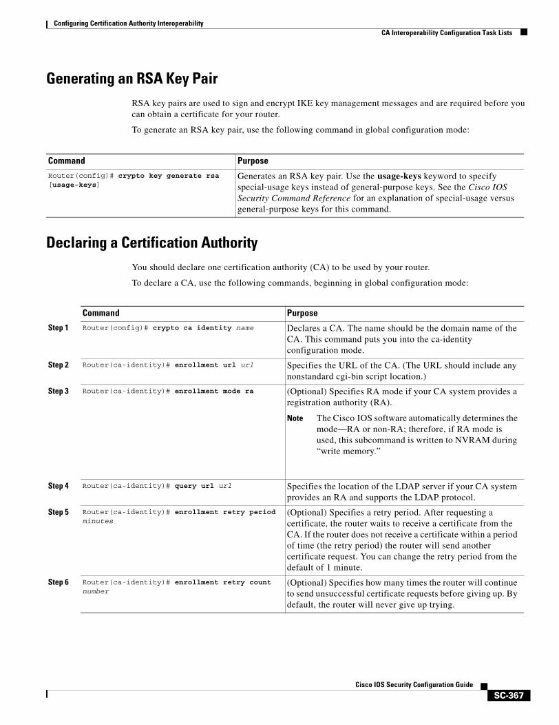
Configuring Certification Authority InteroperabilityCA Interoperability Configuration Task Lists
SC-367Cisco IOS Security Configuration Guide
Generating an RSA Key PairRSA key pairs are used to sign and encrypt IKE key management messages and are required before you can obtain a certificate for your router.
To generate an RSA key pair, use the following command in global configuration mode:
Declaring a Certification AuthorityYou should declare one certification authority (CA) to be used by your router.
To declare a CA, use the following commands, beginning in global configuration mode:
Command Purpose
Router(config)# crypto key generate rsa [usage-keys]
Generates an RSA key pair. Use the usage-keys keyword to specify special-usage keys instead of general-purpose keys. See the Cisco IOS Security Command Reference for an explanation of special-usage versus general-purpose keys for this command.
Command Purpose
Step 1 Router(config)# crypto ca identity name Declares a CA. The name should be the domain name of the CA. This command puts you into the ca-identity configuration mode.
Step 2 Router(ca-identity)# enrollment url url Specifies the URL of the CA. (The URL should include any nonstandard cgi-bin script location.)
Step 3 Router(ca-identity)# enrollment mode ra (Optional) Specifies RA mode if your CA system provides a registration authority (RA).
Note The Cisco IOS software automatically determines the mode—RA or non-RA; therefore, if RA mode is used, this subcommand is written to NVRAM during “write memory.”
Step 4 Router(ca-identity)# query url url Specifies the location of the LDAP server if your CA system provides an RA and supports the LDAP protocol.
Step 5 Router(ca-identity)# enrollment retry period minutes
(Optional) Specifies a retry period. After requesting a certificate, the router waits to receive a certificate from the CA. If the router does not receive a certificate within a period of time (the retry period) the router will send another certificate request. You can change the retry period from the default of 1 minute.
Step 6 Router(ca-identity)# enrollment retry count number
(Optional) Specifies how many times the router will continue to send unsuccessful certificate requests before giving up. By default, the router will never give up trying.
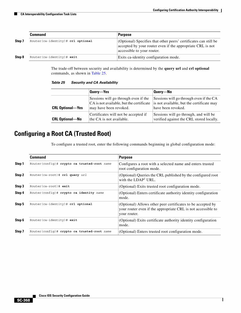
Configuring Certification Authority InteroperabilityCA Interoperability Configuration Task Lists
SC-368Cisco IOS Security Configuration Guide
The trade-off between security and availability is determined by the query url and crl optional commands, as shown in Table 25.
Configuring a Root CA (Trusted Root)To configure a trusted root, enter the following commands beginning in global configuration mode:
Step 7 Router(ca-identity)# crl optional (Optional) Specifies that other peers’ certificates can still be accepted by your router even if the appropriate CRL is not accessible to your router.
Step 8 Router(ca-identity)# exit Exits ca-identity configuration mode.
Command Purpose
Table 25 Security and CA Availability
Query—Yes Query—No
CRL Optional—Yes
Sessions will go through even if the CA is not available, but the certificate may have been revoked.
Sessions will go through even if the CA is not available, but the certificate may have been revoked.
CRL Optional—NoCertificates will not be accepted if the CA is not available.
Sessions will go through, and will be verified against the CRL stored locally.
Command Purpose
Step 1 Router(config)# crypto ca trusted-root name Configures a root with a selected name and enters trusted root configuration mode.
Step 2 Router(ca-root)# crl query url (Optional) Queries the CRL published by the configured root with the LDAP1 URL.
Step 3 Router(ca-root)# exit (Optional) Exits trusted root configuration mode.
Step 4 Router(config)# crypto ca identity name (Optional) Enters certificate authority identity configuration mode.
Step 5 Router(ca-identity)# crl optional (Optional) Allows other peer certificates to be accepted by your router even if the appropriate CRL is not accessible to your router.
Step 6 Router(ca-identity)# exit (Optional) Exits certificate authority identity configuration mode.
Step 7 Router(config)# crypto ca trusted-root name (Optional) Enters trusted root configuration mode.
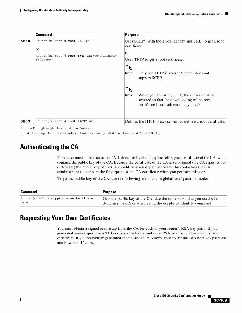
Configuring Certification Authority InteroperabilityCA Interoperability Configuration Task Lists
SC-369Cisco IOS Security Configuration Guide
Authenticating the CAThe router must authenticate the CA. It does this by obtaining the self-signed certificate of the CA, which contains the public key of the CA. Because the certificate of the CA is self-signed (the CA signs its own certificate) the public key of the CA should be manually authenticated by contacting the CA administrator to compare the fingerprint of the CA certificate when you perform this step.
To get the public key of the CA, use the following command in global configuration mode:
Requesting Your Own CertificatesYou must obtain a signed certificate from the CA for each of your router’s RSA key pairs. If you generated general-purpose RSA keys, your router has only one RSA key pair and needs only one certificate. If you previously generated special-usage RSA keys, your router has two RSA key pairs and needs two certificates.
Step 8 Router(ca-root)# root CEP url
or
Router(ca-root)# root TFTP server-hostname filename
Uses SCEP2, with the given identity and URL, to get a root certificate.
or
Uses TFTP to get a root certificate.
Note Only use TFTP if your CA server does not support SCEP.
Note When you are using TFTP, the server must be secured so that the downloading of the root certificate is not subject to any attack.
Step 9 Router(ca-root)# root PROXY url Defines the HTTP proxy server for getting a root certificate.
1. LDAP = Lightweight Directory Access Protocol.
2. SCEP = Simple Certificate Ennrollment Protocol (formerly called Cisco Enrollment Protocol (CEP)).
Command Purpose
Command PurposeRouter(config)# crypto ca authenticate name
Gets the public key of the CA. Use the same name that you used when declaring the CA or when using the crypto ca identity command.
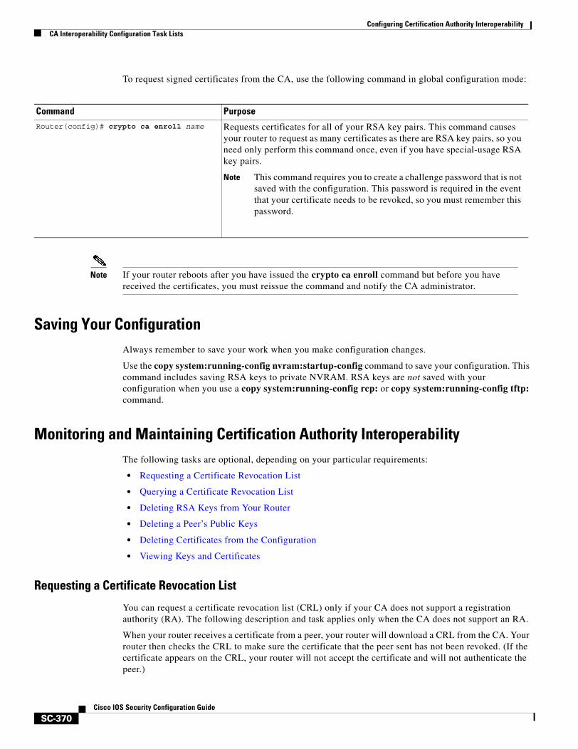
Configuring Certification Authority InteroperabilityCA Interoperability Configuration Task Lists
SC-370Cisco IOS Security Configuration Guide
To request signed certificates from the CA, use the following command in global configuration mode:
Note If your router reboots after you have issued the crypto ca enroll command but before you have received the certificates, you must reissue the command and notify the CA administrator.
Saving Your ConfigurationAlways remember to save your work when you make configuration changes.
Use the copy system:running-config nvram:startup-config command to save your configuration. This command includes saving RSA keys to private NVRAM. RSA keys are not saved with your configuration when you use a copy system:running-config rcp: or copy system:running-config tftp: command.
Monitoring and Maintaining Certification Authority InteroperabilityThe following tasks are optional, depending on your particular requirements:
• Requesting a Certificate Revocation List
• Querying a Certificate Revocation List
• Deleting RSA Keys from Your Router
• Deleting a Peer’s Public Keys
• Deleting Certificates from the Configuration
• Viewing Keys and Certificates
Requesting a Certificate Revocation List
You can request a certificate revocation list (CRL) only if your CA does not support a registration authority (RA). The following description and task applies only when the CA does not support an RA.
When your router receives a certificate from a peer, your router will download a CRL from the CA. Your router then checks the CRL to make sure the certificate that the peer sent has not been revoked. (If the certificate appears on the CRL, your router will not accept the certificate and will not authenticate the peer.)
Command PurposeRouter(config)# crypto ca enroll name Requests certificates for all of your RSA key pairs. This command causes
your router to request as many certificates as there are RSA key pairs, so you need only perform this command once, even if you have special-usage RSA key pairs.
Note This command requires you to create a challenge password that is not saved with the configuration. This password is required in the event that your certificate needs to be revoked, so you must remember this password.
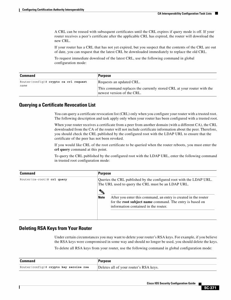
Configuring Certification Authority InteroperabilityCA Interoperability Configuration Task Lists
SC-371Cisco IOS Security Configuration Guide
A CRL can be reused with subsequent certificates until the CRL expires if query mode is off. If your router receives a peer’s certificate after the applicable CRL has expired, the router will download the new CRL.
If your router has a CRL that has not yet expired, but you suspect that the contents of the CRL are out of date, you can request that the latest CRL be downloaded immediately to replace the old CRL.
To request immediate download of the latest CRL, use the following command in global configuration mode:
Querying a Certificate Revocation List
You can query a certificate revocation list (CRL) only when you configure your router with a trusted root. The following description and task apply only when your router has been configured with a trusted root.
When your router receives a certificate from a peer from another domain (with a different CA), the CRL downloaded from the CA of the router will not include certificate information about the peer. Therefore, you should check the CRL published by the configured root with the LDAP URL to ensure that the certificate of the peer has not been revoked.
If you would like CRL of the root certificate to be queried when the router reboots, you must enter the crl query command at this point.
To query the CRL published by the configured root with the LDAP URL, enter the following command in trusted root configuration mode:
Deleting RSA Keys from Your Router
Under certain circumstances you may want to delete your router’s RSA keys. For example, if you believe the RSA keys were compromised in some way and should no longer be used, you should delete the keys.
To delete all RSA keys from your router, use the following command in global configuration mode:
Command Purpose
Router(config)# crypto ca crl request name
Requests an updated CRL.
This command replaces the currently stored CRL at your router with the newest version of the CRL.
Command PurposeRouter(ca-root)# crl query Queries the CRL published by the configured root with the LDAP URL.
The URL used to query the CRL must be an LDAP URL.
Note After you enter this command, an entry is created in the router for the root subject name command. The entry is based on information contained in the router.
Command Purpose
Router(config)# crypto key zeroize rsa Deletes all of your router’s RSA keys.
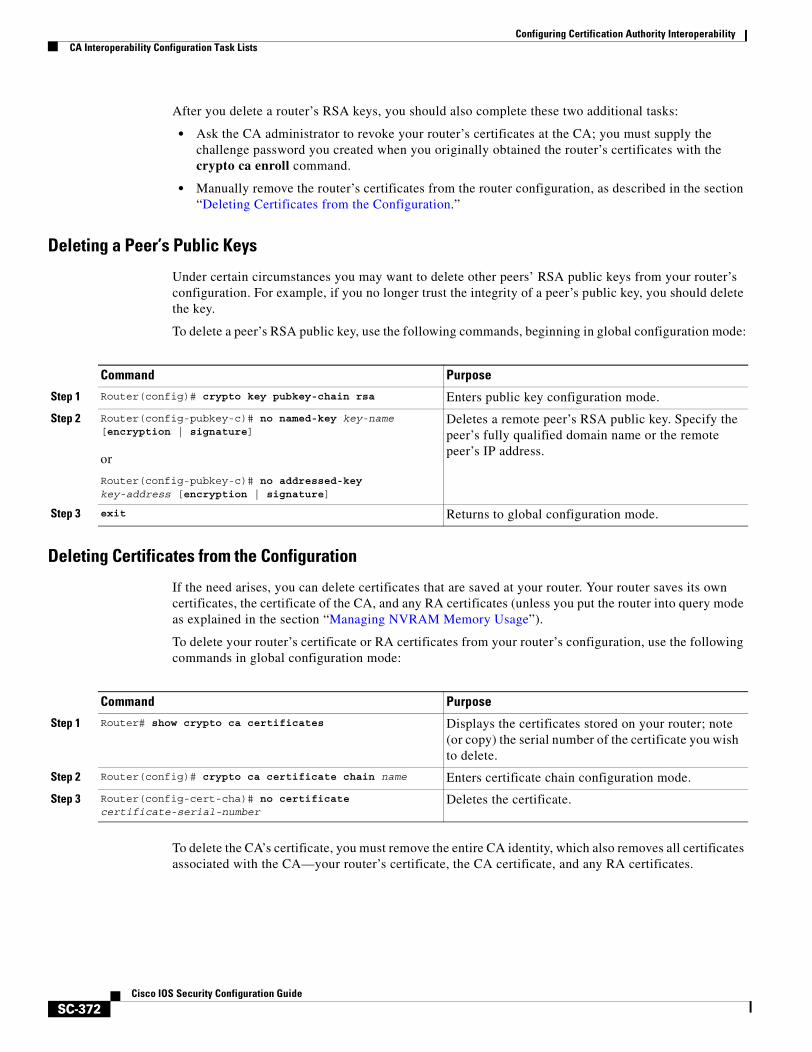
Configuring Certification Authority InteroperabilityCA Interoperability Configuration Task Lists
SC-372Cisco IOS Security Configuration Guide
After you delete a router’s RSA keys, you should also complete these two additional tasks:
• Ask the CA administrator to revoke your router’s certificates at the CA; you must supply the challenge password you created when you originally obtained the router’s certificates with the crypto ca enroll command.
• Manually remove the router’s certificates from the router configuration, as described in the section “Deleting Certificates from the Configuration.”
Deleting a Peer’s Public Keys
Under certain circumstances you may want to delete other peers’ RSA public keys from your router’s configuration. For example, if you no longer trust the integrity of a peer’s public key, you should delete the key.
To delete a peer’s RSA public key, use the following commands, beginning in global configuration mode:
Deleting Certificates from the Configuration
If the need arises, you can delete certificates that are saved at your router. Your router saves its own certificates, the certificate of the CA, and any RA certificates (unless you put the router into query mode as explained in the section “Managing NVRAM Memory Usage”).
To delete your router’s certificate or RA certificates from your router’s configuration, use the following commands in global configuration mode:
To delete the CA’s certificate, you must remove the entire CA identity, which also removes all certificates associated with the CA—your router’s certificate, the CA certificate, and any RA certificates.
Command Purpose
Step 1 Router(config)# crypto key pubkey-chain rsa Enters public key configuration mode.
Step 2 Router(config-pubkey-c)# no named-key key-name [encryption | signature]
or
Router(config-pubkey-c)# no addressed-key key-address [encryption | signature]
Deletes a remote peer’s RSA public key. Specify the peer’s fully qualified domain name or the remote peer’s IP address.
Step 3 exit Returns to global configuration mode.
Command Purpose
Step 1 Router# show crypto ca certificates Displays the certificates stored on your router; note (or copy) the serial number of the certificate you wish to delete.
Step 2 Router(config)# crypto ca certificate chain name Enters certificate chain configuration mode.
Step 3 Router(config-cert-cha)# no certificate certificate-serial-number
Deletes the certificate.
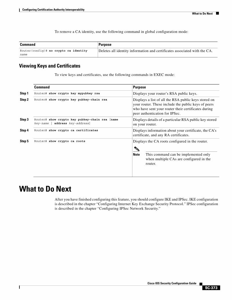
Configuring Certification Authority InteroperabilityWhat to Do Next
SC-373Cisco IOS Security Configuration Guide
To remove a CA identity, use the following command in global configuration mode:
Viewing Keys and Certificates
To view keys and certificates, use the following commands in EXEC mode:
What to Do Next After you have finished configuring this feature, you should configure IKE and IPSec. IKE configuration is described in the chapter “Configuring Internet Key Exchange Security Protocol.” IPSec configuration is described in the chapter “Configuring IPSec Network Security.”
Command PurposeRouter(config)# no crypto ca identity name
Deletes all identity information and certificates associated with the CA.
Command Purpose
Step 1 Router# show crypto key mypubkey rsa Displays your router’s RSA public keys.
Step 2 Router# show crypto key pubkey-chain rsa Displays a list of all the RSA public keys stored on your router. These include the public keys of peers who have sent your router their certificates during peer authentication for IPSec.
Step 3 Router# show crypto key pubkey-chain rsa [name key-name | address key-address]
Displays details of a particular RSA public key stored on your router.
Step 4 Router# show crypto ca certificates Displays information about your certificate, the CA’s certificate, and any RA certificates.
Step 5 Router# show crypto ca roots Displays the CA roots configured in the router.
Note This command can be implemented only when multiple CAs are configured in the router.
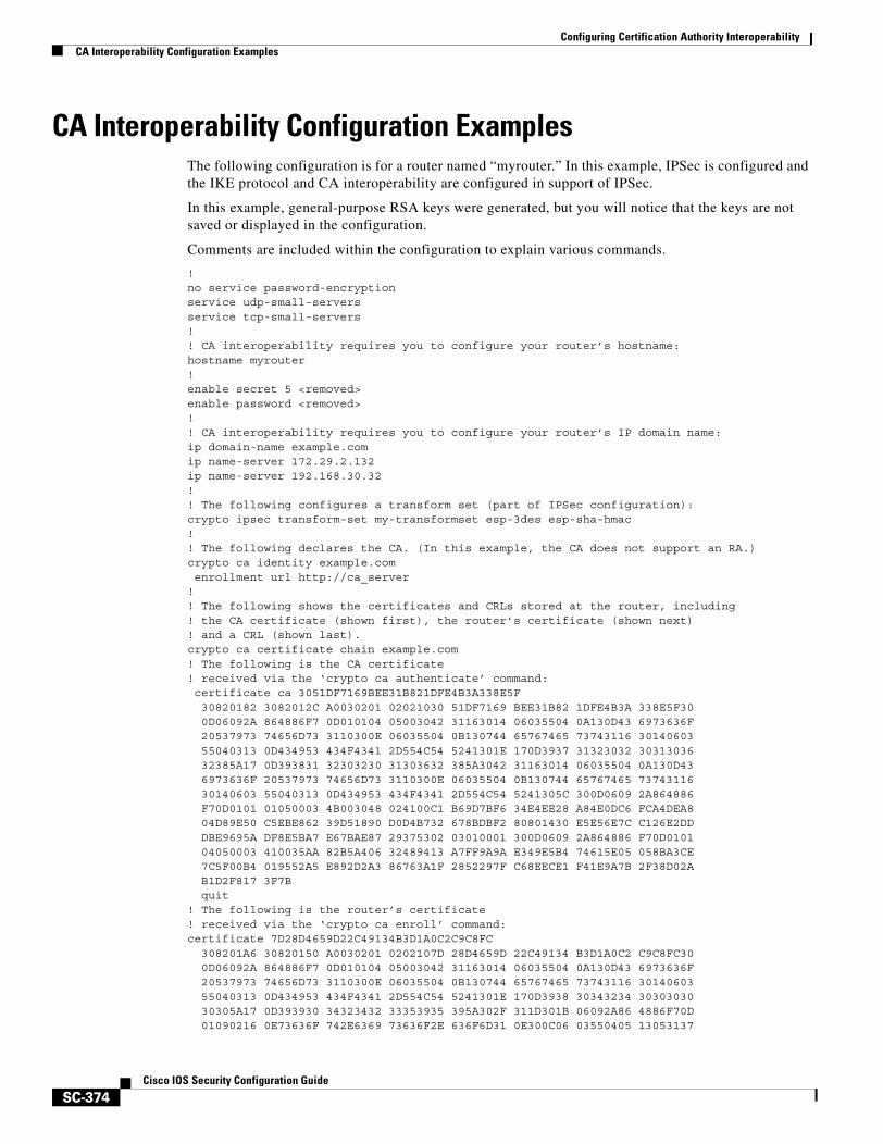
Configuring Certification Authority InteroperabilityCA Interoperability Configuration Examples
SC-374Cisco IOS Security Configuration Guide
CA Interoperability Configuration ExamplesThe following configuration is for a router named “myrouter.” In this example, IPSec is configured and the IKE protocol and CA interoperability are configured in support of IPSec.
In this example, general-purpose RSA keys were generated, but you will notice that the keys are not saved or displayed in the configuration.
Comments are included within the configuration to explain various commands.
!no service password-encryptionservice udp-small-serversservice tcp-small-servers!! CA interoperability requires you to configure your router’s hostname:hostname myrouter!enable secret 5 <removed>enable password <removed>!! CA interoperability requires you to configure your router’s IP domain name:ip domain-name example.comip name-server 172.29.2.132ip name-server 192.168.30.32!! The following configures a transform set (part of IPSec configuration):crypto ipsec transform-set my-transformset esp-3des esp-sha-hmac !! The following declares the CA. (In this example, the CA does not support an RA.)crypto ca identity example.com enrollment url http://ca_server!! The following shows the certificates and CRLs stored at the router, including! the CA certificate (shown first), the router’s certificate (shown next)! and a CRL (shown last).crypto ca certificate chain example.com! The following is the CA certificate! received via the ‘crypto ca authenticate’ command: certificate ca 3051DF7169BEE31B821DFE4B3A338E5F 30820182 3082012C A0030201 02021030 51DF7169 BEE31B82 1DFE4B3A 338E5F30 0D06092A 864886F7 0D010104 05003042 31163014 06035504 0A130D43 6973636F 20537973 74656D73 3110300E 06035504 0B130744 65767465 73743116 30140603 55040313 0D434953 434F4341 2D554C54 5241301E 170D3937 31323032 30313036 32385A17 0D393831 32303230 31303632 385A3042 31163014 06035504 0A130D43 6973636F 20537973 74656D73 3110300E 06035504 0B130744 65767465 73743116 30140603 55040313 0D434953 434F4341 2D554C54 5241305C 300D0609 2A864886 F70D0101 01050003 4B003048 024100C1 B69D7BF6 34E4EE28 A84E0DC6 FCA4DEA8 04D89E50 C5EBE862 39D51890 D0D4B732 678BDBF2 80801430 E5E56E7C C126E2DD DBE9695A DF8E5BA7 E67BAE87 29375302 03010001 300D0609 2A864886 F70D0101 04050003 410035AA 82B5A406 32489413 A7FF9A9A E349E5B4 74615E05 058BA3CE 7C5F00B4 019552A5 E892D2A3 86763A1F 2852297F C68EECE1 F41E9A7B 2F38D02A B1D2F817 3F7B quit! The following is the router’s certificate! received via the ‘crypto ca enroll’ command:certificate 7D28D4659D22C49134B3D1A0C2C9C8FC 308201A6 30820150 A0030201 0202107D 28D4659D 22C49134 B3D1A0C2 C9C8FC30 0D06092A 864886F7 0D010104 05003042 31163014 06035504 0A130D43 6973636F 20537973 74656D73 3110300E 06035504 0B130744 65767465 73743116 30140603 55040313 0D434953 434F4341 2D554C54 5241301E 170D3938 30343234 30303030 30305A17 0D393930 34323432 33353935 395A302F 311D301B 06092A86 4886F70D 01090216 0E73636F 742E6369 73636F2E 636F6D31 0E300C06 03550405 13053137
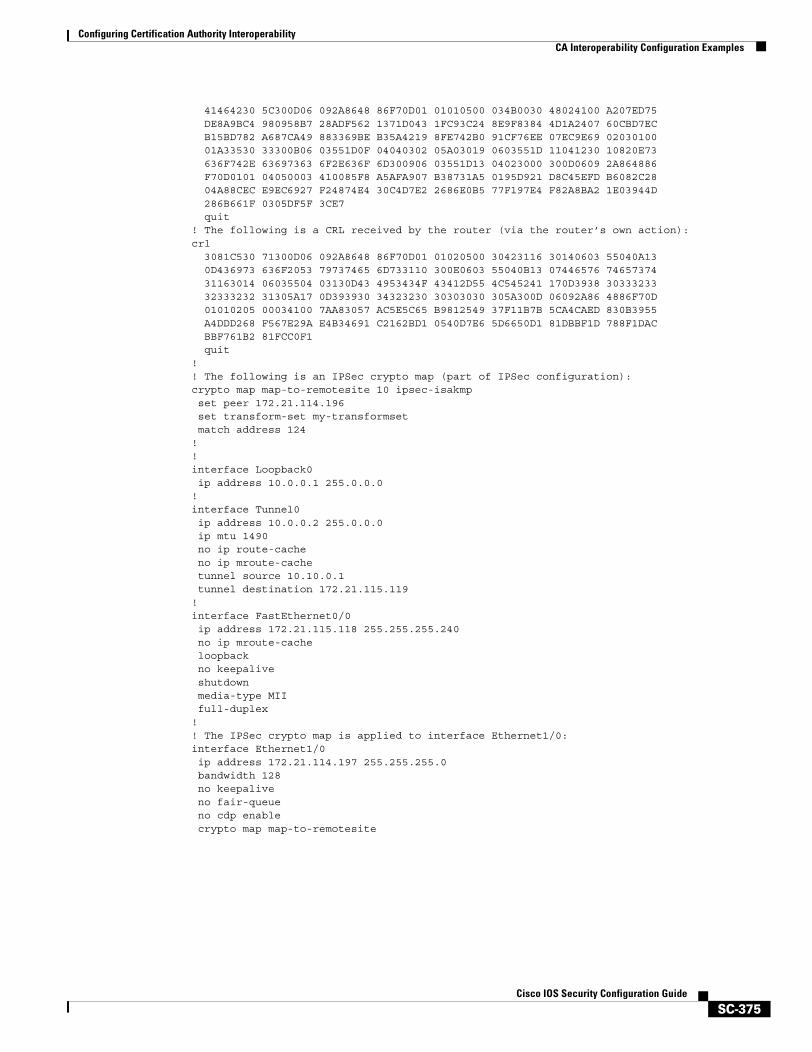
Configuring Certification Authority InteroperabilityCA Interoperability Configuration Examples
SC-375Cisco IOS Security Configuration Guide
41464230 5C300D06 092A8648 86F70D01 01010500 034B0030 48024100 A207ED75 DE8A9BC4 980958B7 28ADF562 1371D043 1FC93C24 8E9F8384 4D1A2407 60CBD7EC B15BD782 A687CA49 883369BE B35A4219 8FE742B0 91CF76EE 07EC9E69 02030100 01A33530 33300B06 03551D0F 04040302 05A03019 0603551D 11041230 10820E73 636F742E 63697363 6F2E636F 6D300906 03551D13 04023000 300D0609 2A864886 F70D0101 04050003 410085F8 A5AFA907 B38731A5 0195D921 D8C45EFD B6082C28 04A88CEC E9EC6927 F24874E4 30C4D7E2 2686E0B5 77F197E4 F82A8BA2 1E03944D 286B661F 0305DF5F 3CE7 quit! The following is a CRL received by the router (via the router’s own action):crl 3081C530 71300D06 092A8648 86F70D01 01020500 30423116 30140603 55040A13 0D436973 636F2053 79737465 6D733110 300E0603 55040B13 07446576 74657374 31163014 06035504 03130D43 4953434F 43412D55 4C545241 170D3938 30333233 32333232 31305A17 0D393930 34323230 30303030 305A300D 06092A86 4886F70D 01010205 00034100 7AA83057 AC5E5C65 B9812549 37F11B7B 5CA4CAED 830B3955 A4DDD268 F567E29A E4B34691 C2162BD1 0540D7E6 5D6650D1 81DBBF1D 788F1DAC BBF761B2 81FCC0F1 quit!! The following is an IPSec crypto map (part of IPSec configuration):crypto map map-to-remotesite 10 ipsec-isakmp set peer 172.21.114.196 set transform-set my-transformset match address 124!!interface Loopback0 ip address 10.0.0.1 255.0.0.0!interface Tunnel0 ip address 10.0.0.2 255.0.0.0 ip mtu 1490 no ip route-cache no ip mroute-cache tunnel source 10.10.0.1 tunnel destination 172.21.115.119!interface FastEthernet0/0 ip address 172.21.115.118 255.255.255.240 no ip mroute-cache loopback no keepalive shutdown media-type MII full-duplex!! The IPSec crypto map is applied to interface Ethernet1/0:interface Ethernet1/0 ip address 172.21.114.197 255.255.255.0 bandwidth 128 no keepalive no fair-queue no cdp enable crypto map map-to-remotesite
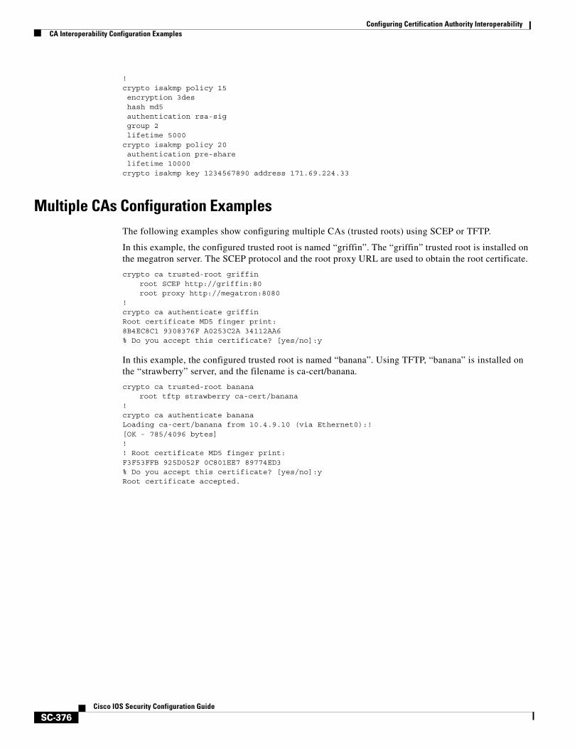
Configuring Certification Authority InteroperabilityCA Interoperability Configuration Examples
SC-376Cisco IOS Security Configuration Guide
!crypto isakmp policy 15encryption 3deshash md5authentication rsa-siggroup 2lifetime 5000
crypto isakmp policy 20authentication pre-sharelifetime 10000
crypto isakmp key 1234567890 address 171.69.224.33
Multiple CAs Configuration ExamplesThe following examples show configuring multiple CAs (trusted roots) using SCEP or TFTP.
In this example, the configured trusted root is named “griffin”. The “griffin” trusted root is installed on the megatron server. The SCEP protocol and the root proxy URL are used to obtain the root certificate.
crypto ca trusted-root griffinroot SCEP http://griffin:80root proxy http://megatron:8080
!crypto ca authenticate griffinRoot certificate MD5 finger print:8B4EC8C1 9308376F A0253C2A 34112AA6 % Do you accept this certificate? [yes/no]:y
In this example, the configured trusted root is named “banana”. Using TFTP, “banana” is installed on the “strawberry” server, and the filename is ca-cert/banana.
crypto ca trusted-root bananaroot tftp strawberry ca-cert/banana
!crypto ca authenticate bananaLoading ca-cert/banana from 10.4.9.10 (via Ethernet0):![OK - 785/4096 bytes]!! Root certificate MD5 finger print:F3F53FFB 925D052F 0C801EE7 89774ED3 % Do you accept this certificate? [yes/no]:yRoot certificate accepted.
SC-377Cisco IOS Security Configuration Guide
Configuring Internet Key Exchange Security Protocol
This chapter describes how to configure the Internet Key Exchange (IKE) protocol. IKE is a key management protocol standard that is used in conjunction with the IPSec standard. IPSec is an IP security feature that provides robust authentication and encryption of IP packets.
IPSec can be configured without IKE, but IKE enhances IPSec by providing additional features, flexibility, and ease of configuration for the IPSec standard.
IKE is a hybrid protocol that implements the Oakley key exchange and the Skeme key exchange inside the Internet Security Association and Key Management Protocol (ISAKMP) framework. (ISAKMP, Oakley, and Skeme are security protocols implemented by IKE.)
For a complete description of the IKE commands used in this chapter, refer to the “Internet Key Exchange Security Protocol Commands” chapter in the Cisco IOS Security Command Reference. To locate documentation of other commands that appear in this chapter, use the command reference master index or search online.
To identify the hardware platform or software image information associated with a feature, use the Feature Navigator on Cisco.com to search for information about the feature or refer to the software release notes for a specific release. For more information, see the “Identifying Supported Platforms” section in the chapter “Using Cisco IOS Software.”
In This ChapterThis chapter includes the following sections:
• About IKE
• IKE Configuration Task List
• What To Do Next
• IKE Configuration Examples
Configuring Internet Key Exchange Security ProtocolAbout IKE
SC-378Cisco IOS Security Configuration Guide
About IKEIKE automatically negotiates IPSec security associations (SAs) and enables IPSec secure communications without costly manual preconfiguration. Specifically, IKE provides these benefits:
• Eliminates the need to manually specify all the IPSec security parameters in the crypto maps at both peers.
• Allows you to specify a lifetime for the IPSec security association.
• Allows encryption keys to change during IPSec sessions.
• Allows IPSec to provide anti-replay services.
• Permits certification authority (CA) support for a manageable, scalable IPSec implementation.
• Allows dynamic authentication of peers.
This section includes the following sections:
• Supported Standards
• List of Terms
• IKE Aggressive Mode Behavior
Supported StandardsCisco implements the following standards:
• IKE—Internet Key Exchange. A hybrid protocol that implements Oakley and Skeme key exchanges inside the ISAKMP framework. IKE can be used with other protocols, but its initial implementation is with the IPSec protocol. IKE provides authentication of the IPSec peers, negotiates IPSec keys, and negotiates IPSec security associations.
IKE is implemented in accordance with RFC 2409, The Internet Key Exchange.
• IPSec—IP Security Protocol. IPSec is a framework of open standards that provides data confidentiality, data integrity, and data authentication between participating peers. IPSec provides these security services at the IP layer; it uses IKE to handle negotiation of protocols and algorithms based on local policy and to generate the encryption and authentication keys to be used by IPSec. IPSec can be used to protect one or more data flows between a pair of hosts, between a pair of security gateways, or between a security gateway and a host.
For more information on IPSec, see the chapter “Configuring IPSec Network Security.”
• ISAKMP—Internet Security Association and Key Management Protocol. A protocol framework that defines payload formats, the mechanics of implementing a key exchange protocol, and the negotiation of a security association.
ISAKMP is implemented in accordance with the latest version of the Internet Security Association and Key Management Protocol (ISAKMP) Internet Draft (RFC 2408).
• Oakley—A key exchange protocol that defines how to derive authenticated keying material.
• Skeme—A key exchange protocol that defines how to derive authenticated keying material, with rapid key refreshment.
Configuring Internet Key Exchange Security ProtocolAbout IKE
SC-379Cisco IOS Security Configuration Guide
The component technologies implemented for use by IKE include the following:
• DES—Data Encryption Standard. An algorithim that is used to encrypt packet data. IKE implements the 56-bit DES-CBC with Explicit IV standard. Cipher Block Chaining (CBC) requires an initialization vector (IV) to start encryption. The IV is explicitly given in the IPSec packet.
Cisco IOS software also implements Triple DES (168-bit) encryption, depending on the software versions available for a specific platform. Triple DES (3DES) is a strong form of encryption that allows sensitive information to be transmitted over untrusted networks. It enables customers, particularly in the finance industry, to utilize network-layer encryption.
Note Cisco IOS images that have strong encryption (including, but not limited to, 56-bit data encryption feature sets) are subject to United States government export controls, and have a limited distribution. Images that are to be installed outside the United States require an export license. Customer orders might be denied or subject to delay because of United States government regulations. Contact your sales representative or distributor for more information, or send e-mail to [email protected].
• Diffie-Hellman—A public-key cryptography protocol that allows two parties to establish a shared secret over an unsecure communications channel. Diffie-Hellman is used within IKE to establish session keys. 768-bit and 1024-bit Diffie-Hellman groups are supported.
• MD5 (HMAC variant)—Message Digest 5. A hash algorithm used to authenticate packet data. HMAC is a variant that provides an additional level of hashing.
• SHA (HMAC variant)—Secure Hash Algorithm. A hash algorithm used to authenticate packet data. HMAC is a variant that provides an additional level of hashing.
• RSA signatures and RSA encrypted nonces—RSA is the public key cryptographic system developed by Ron Rivest, Adi Shamir, and Leonard Adleman. RSA signatures provide nonrepudiation, and RSA encrypted nonces provide repudiation. (Repudation and nonrepudation have to do with traceability.)
IKE interoperates with the following standard:
X.509v3 certificates—Used with the IKE protocol when authentication requires public keys. This certificate support allows the protected network to scale by providing the equivalent of a digital ID card to each device. When two devices wish to communicate, they exchange digital certificates to prove their identity (thus removing the need to manually exchange public keys with each peer or to manually specify a shared key at each peer).
List of Terms
Anti-Replay
Anti-replay is a security service in which the receiver can reject old or duplicate packets in order to protect itself against replay attacks. IPSec provides optional anti-replay services by use of a sequence number combined with the use of authentication.
Data Authentication
Data authentication includes two concepts:
• Data integrity (verifying that data has not been altered)
• Data origin authentication (verifying that the data was actually sent by the claimed sender)
Data authentication can refer either to integrity alone or to both of these concepts (although data origin authentication is dependent upon data integrity).
Configuring Internet Key Exchange Security ProtocolAbout IKE
SC-380Cisco IOS Security Configuration Guide
Peer
In the context of this chapter, “peer” refers to a router or other device that participates in IPSec and IKE.
Perfect Forward Secrecy
Perfect forward secrecy (PFS) is a cryptographic characteristic associated with a derived shared secret value. With PFS, if one key is compromised, previous and subsequent keys are not also compromised, because subsequent keys are not derived from previous keys.
Repudiation
Repudation is a quality that prevents a third party from being able to prove that a communication between two other parties ever took place. This is a desirable quality if you do not want your communications to be traceable. Nonrepudiation is the opposite quality—a third party can prove that a communication between two other parties took place. Nonrepudiation is desirable if you want to be able to trace your communications and prove that they occurred.
Security Association
A security association (SA) describes how two or more entities will utilize security services to communicate securely. For example, an IPSec SA defines the encryption algorithm (if used), the authentication algorithm, and the shared session key to be used during the IPSec connection.
Both IPSec and IKE require and use SAs to identify the parameters of their connections. IKE can negotiate and establish its own SA. The IPSec SA is established either by IKE or by manual user configuration.
IKE Aggressive Mode BehaviorThis section describes IKE aggressive mode behavior occurring when Cisco IOS software is used.
IKE has two phases of key negotiation: phase 1 and phase 2. Phase 1 negotiates a security association (a key) between two IKE peers. The key negotiated in phase 1 enables IKE peers to communicate securely in phase 2. During phase 2 negotiation, IKE establishes keys (security associations) for other applications, such as IPSec.
Phase 1 negotiation can occur using one of two modes: main mode and aggressive mode. Main mode tries to protect all information during the negotiation, meaning that no information is available to a potential attacker. When main mode is used, the identities of the two sides are hidden. Although this mode of operation is very secure, it is relatively costly in terms of the time it takes to complete the negotiation. Aggressive mode takes less time to negotiate keys between peers; however, it gives up some of the security provided by main mode negotiation. For example, the identities of the two parties trying to establish a security association are exposed to an eavesdropper.
The two modes serve different purposes and have different strengths. Main mode is slower than aggressive mode, but main mode is more secure and more flexible because it can offer an IKE peer more security proposals than aggressive mode. Aggressive mode is less flexible and not as secure, but much faster.
In Cisco IOS software, the two modes are not configurable. The default action for IKE authentication (rsa-sig, rsa-encr, or preshared) is to initiate main mode; however, in cases where there is no corresponding information to initiate authentication, and there is a preshared key associated with the host name of the peer, Cisco IOS software can initiate aggressive mode. Cisco IOS software will respond in aggressive mode to an IKE peer that initiates aggressive mode.
Configuring Internet Key Exchange Security ProtocolIKE Configuration Task List
SC-381Cisco IOS Security Configuration Guide
Whether Cisco IOS software initiates main mode or aggressive mode, the following restrictions are applicable:
• The initiating router must not have a certificate associated with the remote peer.
• The preshared key must be by fully qualified domain name (FQDN) on both peers.; thus, you have to enter the crypto isakmp key keystring hostname peer-address command in configuration mode.
• The communicating routers must have a FQDN host entry for each other in their configurations.
• The communicating routers must be configured to authenticate by hostname, not by IP address; thus, you should use the crypto isakmp identity hostname command.
IKE Configuration Task ListTo configure IKE, perform the tasks in the following sections. The tasks in the first three sections are required; the remaining may be optional, depending on what parameters are configured.
• Enabling or Disabling IKE (Required)
• Ensuring That Access Lists Are Compatible with IKE (Required)
• Creating IKE Policies (Required)
• Manually Configuring RSA Keys (Optional, depending on IKE parameters)
• Configuring Preshared Keys (Optional, depending on IKE parameters)
• Configuring Mask Preshared Keys (Optional, depending on IKE parameters)
• Configuring Preshared Keys Using a AAA Server (Optional, depending on IKE parameters)
• Configuring Internet Key Exchange Mode Configuration (Optional)
• Configuring Internet Key Exchange Extended Authentication (Xauth) (Optional)
• Configuring Tunnel Endpoint Discovery (TED) (Optional)
• Clearing IKE Connections (Optional)
• Troubleshooting IKE (Optional)
For IKE configuration examples, refer to the section “IKE Configuration Examples” at the end of this chapter.
Enabling or Disabling IKEIKE is enabled by default. IKE does not have to be enabled for individual interfaces, but it is enabled globally for all interfaces at the router.
If you do not want IKE to be used with your IPSec implementation, you can disable it at all IPSec peers.
If you disable IKE, you will have to make these concessions at the peers:
• You must manually specify all the IPSec security associations in the crypto maps at all peers. (Crypto map configuration is described in the chapter “Configuring IPSec Network Security.”)
• The IPSec security associations of the peers will never time out for a given IPSec session.
• During IPSec sessions between the peers, the encryption keys will never change.
• Anti-replay services will not be available between the peers.
• Certification authority (CA) support cannot be used.
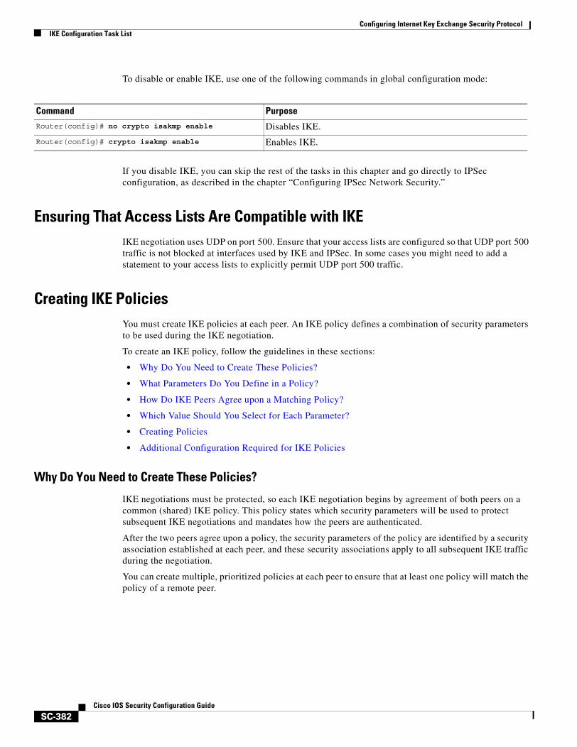
Configuring Internet Key Exchange Security ProtocolIKE Configuration Task List
SC-382Cisco IOS Security Configuration Guide
To disable or enable IKE, use one of the following commands in global configuration mode:
If you disable IKE, you can skip the rest of the tasks in this chapter and go directly to IPSec configuration, as described in the chapter “Configuring IPSec Network Security.”
Ensuring That Access Lists Are Compatible with IKEIKE negotiation uses UDP on port 500. Ensure that your access lists are configured so that UDP port 500 traffic is not blocked at interfaces used by IKE and IPSec. In some cases you might need to add a statement to your access lists to explicitly permit UDP port 500 traffic.
Creating IKE PoliciesYou must create IKE policies at each peer. An IKE policy defines a combination of security parameters to be used during the IKE negotiation.
To create an IKE policy, follow the guidelines in these sections:
• Why Do You Need to Create These Policies?
• What Parameters Do You Define in a Policy?
• How Do IKE Peers Agree upon a Matching Policy?
• Which Value Should You Select for Each Parameter?
• Creating Policies
• Additional Configuration Required for IKE Policies
Why Do You Need to Create These Policies?
IKE negotiations must be protected, so each IKE negotiation begins by agreement of both peers on a common (shared) IKE policy. This policy states which security parameters will be used to protect subsequent IKE negotiations and mandates how the peers are authenticated.
After the two peers agree upon a policy, the security parameters of the policy are identified by a security association established at each peer, and these security associations apply to all subsequent IKE traffic during the negotiation.
You can create multiple, prioritized policies at each peer to ensure that at least one policy will match the policy of a remote peer.
Command PurposeRouter(config)# no crypto isakmp enable Disables IKE.
Router(config)# crypto isakmp enable Enables IKE.
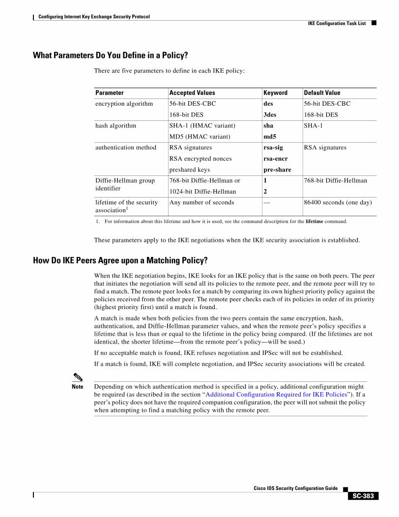
Configuring Internet Key Exchange Security ProtocolIKE Configuration Task List
SC-383Cisco IOS Security Configuration Guide
What Parameters Do You Define in a Policy?
There are five parameters to define in each IKE policy:
These parameters apply to the IKE negotiations when the IKE security association is established.
How Do IKE Peers Agree upon a Matching Policy?
When the IKE negotiation begins, IKE looks for an IKE policy that is the same on both peers. The peer that initiates the negotiation will send all its policies to the remote peer, and the remote peer will try to find a match. The remote peer looks for a match by comparing its own highest priority policy against the policies received from the other peer. The remote peer checks each of its policies in order of its priority (highest priority first) until a match is found.
A match is made when both policies from the two peers contain the same encryption, hash, authentication, and Diffie-Hellman parameter values, and when the remote peer’s policy specifies a lifetime that is less than or equal to the lifetime in the policy being compared. (If the lifetimes are not identical, the shorter lifetime—from the remote peer’s policy—will be used.)
If no acceptable match is found, IKE refuses negotiation and IPSec will not be established.
If a match is found, IKE will complete negotiation, and IPSec security associations will be created.
Note Depending on which authentication method is specified in a policy, additional configuration might be required (as described in the section “Additional Configuration Required for IKE Policies”). If a peer’s policy does not have the required companion configuration, the peer will not submit the policy when attempting to find a matching policy with the remote peer.
Parameter Accepted Values Keyword Default Value
encryption algorithm 56-bit DES-CBC
168-bit DES
des
3des
56-bit DES-CBC
168-bit DES
hash algorithm SHA-1 (HMAC variant)
MD5 (HMAC variant)
sha
md5
SHA-1
authentication method RSA signatures
RSA encrypted nonces
preshared keys
rsa-sig
rsa-encr
pre-share
RSA signatures
Diffie-Hellman group identifier
768-bit Diffie-Hellman or
1024-bit Diffie-Hellman
1
2
768-bit Diffie-Hellman
lifetime of the security association1
1. For information about this lifetime and how it is used, see the command description for the lifetime command.
Any number of seconds — 86400 seconds (one day)
Configuring Internet Key Exchange Security ProtocolIKE Configuration Task List
SC-384Cisco IOS Security Configuration Guide
Which Value Should You Select for Each Parameter?
You can select certain values for each parameter, in accordance with the IKE standard. But why chose one value over another?
If you are interoperating with a device that supports only one of the values for a parameter, your choice is limited to the value supported by the other device. Aside from this, there is often a trade-off between security and performance, and many of these parameter values represent such a trade-off. You should evaluate the level of security risks for your network and your tolerance for these risks. Then the following tips might help you select which value to specify for each parameter:
• The encryption algorithm has two options: 56-bit DES-CBC and 168-bit DES.
• The hash algorithm has two options: SHA-1 and MD5.
MD5 has a smaller digest and is considered to be slightly faster than SHA-1. There has been a demonstrated successful (but extremely difficult) attack against MD5; however, the HMAC variant used by IKE prevents this attack.
• The authentication method has three options: RSA signatures, RSA encrypted nonces, and preshared keys.
– RSA signatures provide nonrepudiation for the IKE negotiation (you can prove to a third party after the fact that you did indeed have an IKE negotiation with the remote peer).
RSA signatures allow the use of a certification authority (CA). Using a CA can dramatically improve the manageability and scalability of your IPSec network. Additionally, RSA signature-based authentication uses only two public key operations, whereas RAS encryption uses four public key operations, making it costlier in terms of overall performance.
You can also exchange the public keys manually, as described in section “Manually Configuring RSA Keys.”
– RSA encrypted nonces provide repudiation for the IKE negotiation (you cannot prove to a third party that you had an IKE negotiation with the remote peer).
RSA encrypted nonces require that peers possess each other’s public keys but do not use a certification authority. Instead, there are two ways for peers to get each other’s public keys:
1) During configuration you manually configure RSA keys (as described in the section “Manually Configuring RSA Keys”).
2) If your local peer has previously used RSA signatures with certificates during a successful IKE negotiation with a remote peer, your local peer already possesses the remote peer’s public key. (The peers’ public keys are exchanged during the RSA-signatures-based IKE negotiations, if certificates are used.)
– Preshared keys are clumsy to use if your secured network is large, and they do not scale well with a growing network. However, they do not require use of a certification authority, as do RSA signatures, and might be easier to set up in a small network with fewer than 10 nodes. RSA signatures also can be considered more secure when compared with preshared key authentication.
• The Diffie-Hellman group identifier has two options: 768-bit and 1024-bit Diffie-Hellman.
The 1024-bit Diffie-Hellman option is harder to crack, but requires more CPU time to execute.
• The lifetime of the security association can be set to any value.
As a general rule, the shorter the lifetime (up to a point), the more secure your IKE negotiations will be. However, with longer lifetimes, future IPSec security associations can be set up more quickly. For more information about this parameter and how it is used, see the command description for the lifetime command.
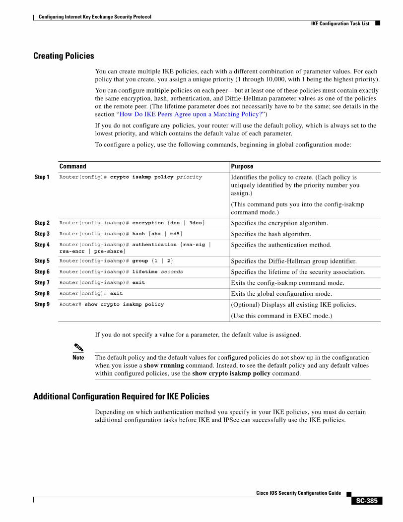
Configuring Internet Key Exchange Security ProtocolIKE Configuration Task List
SC-385Cisco IOS Security Configuration Guide
Creating Policies
You can create multiple IKE policies, each with a different combination of parameter values. For each policy that you create, you assign a unique priority (1 through 10,000, with 1 being the highest priority).
You can configure multiple policies on each peer—but at least one of these policies must contain exactly the same encryption, hash, authentication, and Diffie-Hellman parameter values as one of the policies on the remote peer. (The lifetime parameter does not necessarily have to be the same; see details in the section “How Do IKE Peers Agree upon a Matching Policy?”)
If you do not configure any policies, your router will use the default policy, which is always set to the lowest priority, and which contains the default value of each parameter.
To configure a policy, use the following commands, beginning in global configuration mode:
If you do not specify a value for a parameter, the default value is assigned.
Note The default policy and the default values for configured policies do not show up in the configuration when you issue a show running command. Instead, to see the default policy and any default values within configured policies, use the show crypto isakmp policy command.
Additional Configuration Required for IKE Policies
Depending on which authentication method you specify in your IKE policies, you must do certain additional configuration tasks before IKE and IPSec can successfully use the IKE policies.
Command Purpose
Step 1 Router(config)# crypto isakmp policy priority Identifies the policy to create. (Each policy is uniquely identified by the priority number you assign.)
(This command puts you into the config-isakmp command mode.)
Step 2 Router(config-isakmp)# encryption {des | 3des} Specifies the encryption algorithm.
Step 3 Router(config-isakmp)# hash {sha | md5} Specifies the hash algorithm.
Step 4 Router(config-isakmp)# authentication {rsa-sig | rsa-encr | pre-share}
Specifies the authentication method.
Step 5 Router(config-isakmp)# group {1 | 2} Specifies the Diffie-Hellman group identifier.
Step 6 Router(config-isakmp)# lifetime seconds Specifies the lifetime of the security association.
Step 7 Router(config-isakmp)# exit Exits the config-isakmp command mode.
Step 8 Router(config)# exit Exits the global configuration mode.
Step 9 Router# show crypto isakmp policy (Optional) Displays all existing IKE policies.
(Use this command in EXEC mode.)
Configuring Internet Key Exchange Security ProtocolIKE Configuration Task List
SC-386Cisco IOS Security Configuration Guide
Each authentication method requires additional companion configuration as follows:
• RSA signatures method:
If you specify RSA signatures as the authentication method in a policy, you may configure the peers to obtain certificates from a certification authority (CA). (The CA must be properly configured to issue the certificates.) Configure this certificate support as described in the chapter “Configuring Certification Authority Interoperability.”
The certificates are used by each peer to exchange public keys securely. (RSA signatures requires that each peer has the public signature key of the remote peer.) When both peers have valid certificates, they will automatically exchange public keys with each other as part of any IKE negotiation in which RSA signatures are used.
You may also wish to exchange the public keys manually, as described in the section “Manually Configuring RSA Keys.”
• RSA encrypted nonces method:
If you specify RSA encrypted nonces as the authentication method in a policy, you must ensure that each peer has the public keys of the other peers.
Unlike RSA signatures, the RSA encrypted nonces method can not use certificates to exchange public keys. Instead, you ensure that each peer has the others’ public keys by one of the following methods:
– Manually configuring RSA keys as described in the section “Manually Configuring RSA Keys.”
or
– Ensuring that an IKE exchange using RSA signatures with certificates has already occurred between the peers. (The peers’ public keys are exchanged during the RSA-signatures-based IKE negotiations if certificates are used.)
To make this happen, specify two policies: a higher-priority policy with RSA encrypted nonces and a lower-priority policy with RSA signatures. When IKE negotiations occur, RSA signatures will be used the first time because the peers do not yet have each other’s public keys. Then future IKE negotiations will be able to use RSA encrypted nonces because the public keys will have been exchanged.
This alternative requires that you have certification authority support configured.
• Preshared keys authentication method:
If you specify preshared keys as the authentication method in a policy, you must configure these preshared keys as described in the section “Configuring Preshared Keys.”
If RSA encryption is configured and signature mode is negotiated (and certificates are used for signature mode), the peer will request both signature and encryption keys. Basically, the router will request as many keys as the configuration will support. If RSA encryption is not configured, it will just request a signature key.
Manually Configuring RSA KeysManually configure RSA keys when you specify RSA encrypted nonces as the authentication method in an IKE policy and you are not using a certification authority (CA).
To manually configure RSA keys, perform these tasks at each IPSec peer that uses RSA encrypted nonces in an IKE policy:
• Generating RSA Keys
• Setting ISAKMP Identity
• Specifying RSA Public Keys of All the Other Peers
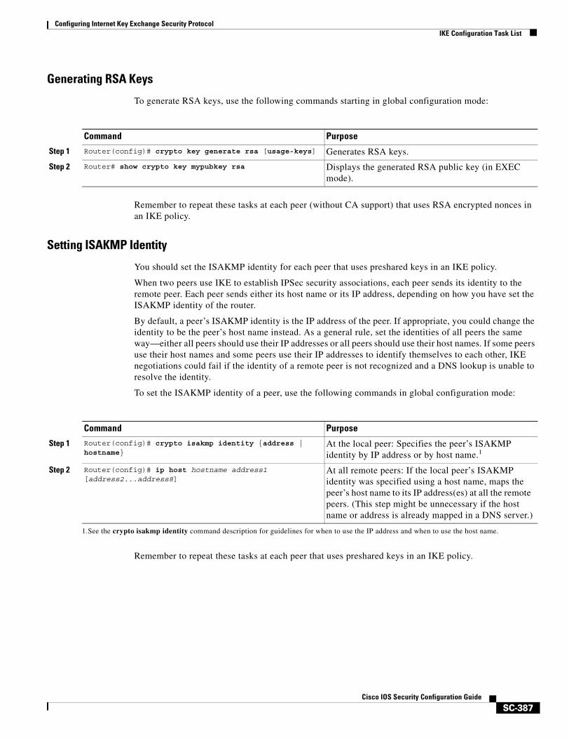
Configuring Internet Key Exchange Security ProtocolIKE Configuration Task List
SC-387Cisco IOS Security Configuration Guide
Generating RSA Keys
To generate RSA keys, use the following commands starting in global configuration mode:
Remember to repeat these tasks at each peer (without CA support) that uses RSA encrypted nonces in an IKE policy.
Setting ISAKMP Identity
You should set the ISAKMP identity for each peer that uses preshared keys in an IKE policy.
When two peers use IKE to establish IPSec security associations, each peer sends its identity to the remote peer. Each peer sends either its host name or its IP address, depending on how you have set the ISAKMP identity of the router.
By default, a peer’s ISAKMP identity is the IP address of the peer. If appropriate, you could change the identity to be the peer’s host name instead. As a general rule, set the identities of all peers the same way—either all peers should use their IP addresses or all peers should use their host names. If some peers use their host names and some peers use their IP addresses to identify themselves to each other, IKE negotiations could fail if the identity of a remote peer is not recognized and a DNS lookup is unable to resolve the identity.
To set the ISAKMP identity of a peer, use the following commands in global configuration mode:
Remember to repeat these tasks at each peer that uses preshared keys in an IKE policy.
Command Purpose
Step 1 Router(config)# crypto key generate rsa [usage-keys] Generates RSA keys.
Step 2 Router# show crypto key mypubkey rsa Displays the generated RSA public key (in EXEC mode).
Command Purpose
Step 1 Router(config)# crypto isakmp identity {address | hostname}
At the local peer: Specifies the peer’s ISAKMP identity by IP address or by host name.1
1.See the crypto isakmp identity command description for guidelines for when to use the IP address and when to use the host name.
Step 2 Router(config)# ip host hostname address1 [address2...address8]
At all remote peers: If the local peer’s ISAKMP identity was specified using a host name, maps the peer’s host name to its IP address(es) at all the remote peers. (This step might be unnecessary if the host name or address is already mapped in a DNS server.)
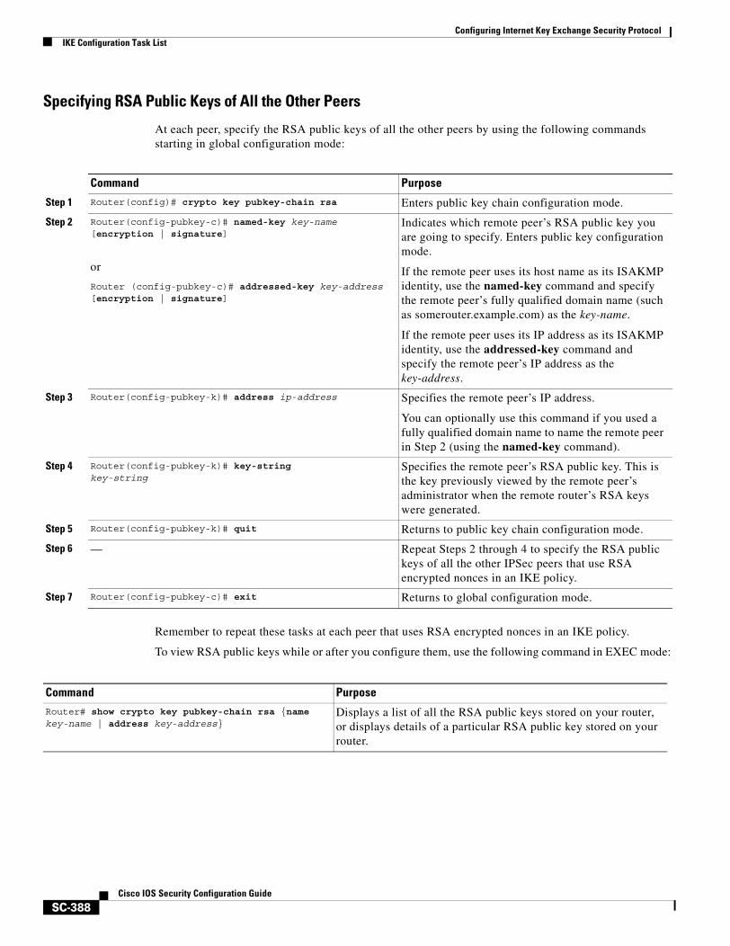
Configuring Internet Key Exchange Security ProtocolIKE Configuration Task List
SC-388Cisco IOS Security Configuration Guide
Specifying RSA Public Keys of All the Other Peers
At each peer, specify the RSA public keys of all the other peers by using the following commands starting in global configuration mode:
Remember to repeat these tasks at each peer that uses RSA encrypted nonces in an IKE policy.
To view RSA public keys while or after you configure them, use the following command in EXEC mode:
Command Purpose
Step 1 Router(config)# crypto key pubkey-chain rsa Enters public key chain configuration mode.
Step 2 Router(config-pubkey-c)# named-key key-name [encryption | signature]
or
Router (config-pubkey-c)# addressed-key key-address [encryption | signature]
Indicates which remote peer’s RSA public key you are going to specify. Enters public key configuration mode.
If the remote peer uses its host name as its ISAKMP identity, use the named-key command and specify the remote peer’s fully qualified domain name (such as somerouter.example.com) as the key-name.
If the remote peer uses its IP address as its ISAKMP identity, use the addressed-key command and specify the remote peer’s IP address as the key-address.
Step 3 Router(config-pubkey-k)# address ip-address Specifies the remote peer’s IP address.
You can optionally use this command if you used a fully qualified domain name to name the remote peer in Step 2 (using the named-key command).
Step 4 Router(config-pubkey-k)# key-stringkey-string
Specifies the remote peer’s RSA public key. This is the key previously viewed by the remote peer’s administrator when the remote router’s RSA keys were generated.
Step 5 Router(config-pubkey-k)# quit Returns to public key chain configuration mode.
Step 6 — Repeat Steps 2 through 4 to specify the RSA public keys of all the other IPSec peers that use RSA encrypted nonces in an IKE policy.
Step 7 Router(config-pubkey-c)# exit Returns to global configuration mode.
Command PurposeRouter# show crypto key pubkey-chain rsa {name key-name | address key-address}
Displays a list of all the RSA public keys stored on your router, or displays details of a particular RSA public key stored on your router.
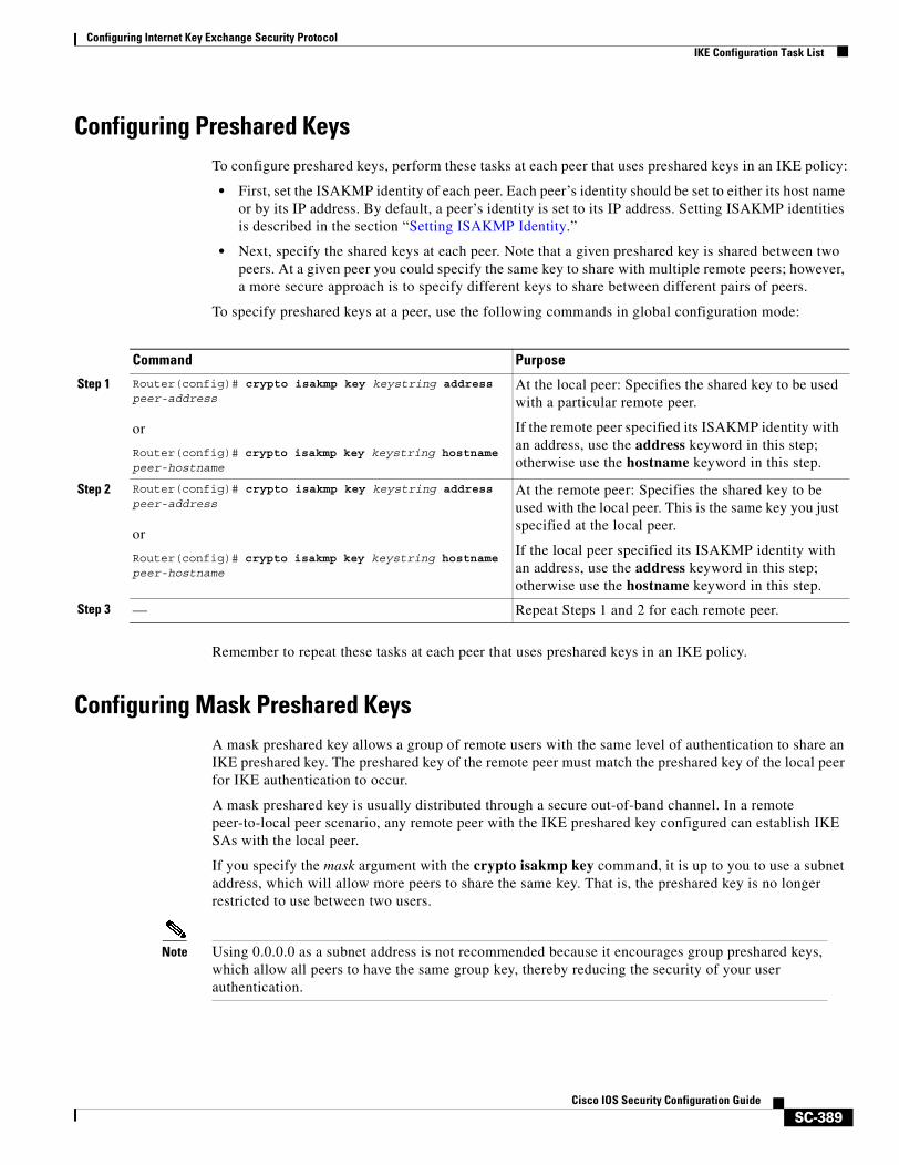
Configuring Internet Key Exchange Security ProtocolIKE Configuration Task List
SC-389Cisco IOS Security Configuration Guide
Configuring Preshared KeysTo configure preshared keys, perform these tasks at each peer that uses preshared keys in an IKE policy:
• First, set the ISAKMP identity of each peer. Each peer’s identity should be set to either its host name or by its IP address. By default, a peer’s identity is set to its IP address. Setting ISAKMP identities is described in the section “Setting ISAKMP Identity.”
• Next, specify the shared keys at each peer. Note that a given preshared key is shared between two peers. At a given peer you could specify the same key to share with multiple remote peers; however, a more secure approach is to specify different keys to share between different pairs of peers.
To specify preshared keys at a peer, use the following commands in global configuration mode:
Remember to repeat these tasks at each peer that uses preshared keys in an IKE policy.
Configuring Mask Preshared KeysA mask preshared key allows a group of remote users with the same level of authentication to share an IKE preshared key. The preshared key of the remote peer must match the preshared key of the local peer for IKE authentication to occur.
A mask preshared key is usually distributed through a secure out-of-band channel. In a remote peer-to-local peer scenario, any remote peer with the IKE preshared key configured can establish IKE SAs with the local peer.
If you specify the mask argument with the crypto isakmp key command, it is up to you to use a subnet address, which will allow more peers to share the same key. That is, the preshared key is no longer restricted to use between two users.
Note Using 0.0.0.0 as a subnet address is not recommended because it encourages group preshared keys, which allow all peers to have the same group key, thereby reducing the security of your user authentication.
Command Purpose
Step 1 Router(config)# crypto isakmp key keystring address peer-address
or
Router(config)# crypto isakmp key keystring hostname peer-hostname
At the local peer: Specifies the shared key to be used with a particular remote peer.
If the remote peer specified its ISAKMP identity with an address, use the address keyword in this step; otherwise use the hostname keyword in this step.
Step 2 Router(config)# crypto isakmp key keystring address peer-address
or
Router(config)# crypto isakmp key keystring hostname peer-hostname
At the remote peer: Specifies the shared key to be used with the local peer. This is the same key you just specified at the local peer.
If the local peer specified its ISAKMP identity with an address, use the address keyword in this step; otherwise use the hostname keyword in this step.
Step 3 — Repeat Steps 1 and 2 for each remote peer.
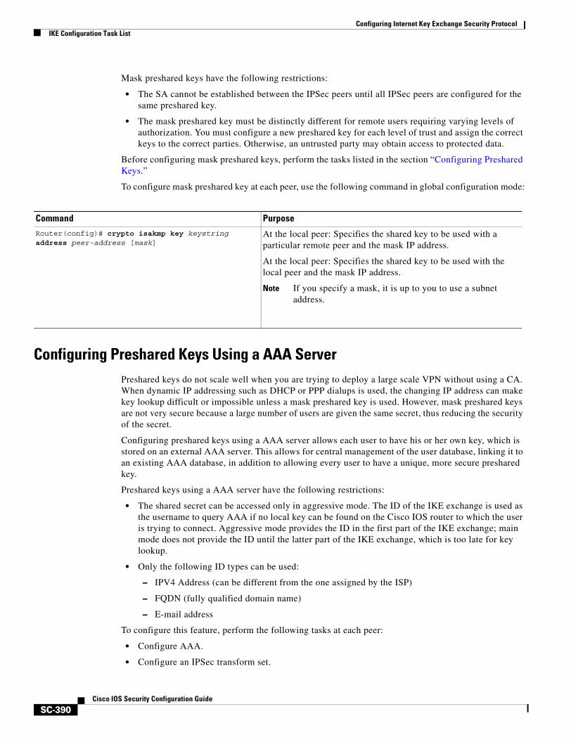
Configuring Internet Key Exchange Security ProtocolIKE Configuration Task List
SC-390Cisco IOS Security Configuration Guide
Mask preshared keys have the following restrictions:
• The SA cannot be established between the IPSec peers until all IPSec peers are configured for the same preshared key.
• The mask preshared key must be distinctly different for remote users requiring varying levels of authorization. You must configure a new preshared key for each level of trust and assign the correct keys to the correct parties. Otherwise, an untrusted party may obtain access to protected data.
Before configuring mask preshared keys, perform the tasks listed in the section “Configuring Preshared Keys.”
To configure mask preshared key at each peer, use the following command in global configuration mode:
Configuring Preshared Keys Using a AAA Server Preshared keys do not scale well when you are trying to deploy a large scale VPN without using a CA. When dynamic IP addressing such as DHCP or PPP dialups is used, the changing IP address can make key lookup difficult or impossible unless a mask preshared key is used. However, mask preshared keys are not very secure because a large number of users are given the same secret, thus reducing the security of the secret.
Configuring preshared keys using a AAA server allows each user to have his or her own key, which is stored on an external AAA server. This allows for central management of the user database, linking it to an existing AAA database, in addition to allowing every user to have a unique, more secure preshared key.
Preshared keys using a AAA server have the following restrictions:
• The shared secret can be accessed only in aggressive mode. The ID of the IKE exchange is used as the username to query AAA if no local key can be found on the Cisco IOS router to which the user is trying to connect. Aggressive mode provides the ID in the first part of the IKE exchange; main mode does not provide the ID until the latter part of the IKE exchange, which is too late for key lookup.
• Only the following ID types can be used:
– IPV4 Address (can be different from the one assigned by the ISP)
– FQDN (fully qualified domain name)
– E-mail address
To configure this feature, perform the following tasks at each peer:
• Configure AAA.
• Configure an IPSec transform set.
Command Purpose
Router(config)# crypto isakmp key keystring address peer-address [mask]
At the local peer: Specifies the shared key to be used with a particular remote peer and the mask IP address.
At the local peer: Specifies the shared key to be used with the local peer and the mask IP address.
Note If you specify a mask, it is up to you to use a subnet address.
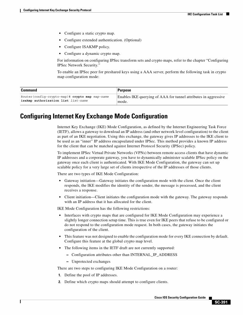
Configuring Internet Key Exchange Security ProtocolIKE Configuration Task List
SC-391Cisco IOS Security Configuration Guide
• Configure a static crypto map.
• Configure extended authentication. (Optional)
• Configure ISAKMP policy.
• Configure a dynamic crypto map.
For information on configuring IPSec transform sets and crypto maps, refer to the chapter “Configuring IPSec Network Security.”
To enable an IPSec peer for preshared keys using a AAA server, perform the following task in crypto map configuration mode:
Configuring Internet Key Exchange Mode ConfigurationInternet Key Exchange (IKE) Mode Configuration, as defined by the Internet Engineering Task Force (IETF), allows a gateway to download an IP address (and other network level configuration) to the client as part of an IKE negotiation. Using this exchange, the gateway gives IP addresses to the IKE client to be used as an “inner” IP address encapsulated under IPSec. This method provides a known IP address for the client that can be matched against Internet Protocol Security (IPSec) policy.
To implement IPSec Virtual Private Networks (VPNs) between remote access clients that have dynamic IP addresses and a corporate gateway, you have to dynamically administer scalable IPSec policy on the gateway once each client is authenticated. With IKE Mode Configuration, the gateway can set up scalable policy for a very large set of clients irrespective of the IP addresses of those clients.
There are two types of IKE Mode Configuration:
• Gateway initiation—Gateway initiates the configuration mode with the client. Once the client responds, the IKE modifies the identity of the sender, the message is processed, and the client receives a response.
• Client initiation—Client initiates the configuration mode with the gateway. The gateway responds with an IP address that it has allocated for the client.
IKE Mode Configuration has the following restrictions:
• Interfaces with crypto maps that are configured for IKE Mode Configuration may experience a slightly longer connection setup time. This is true even for IKE peers that refuse to be configured or do not respond to the configuration mode request. In both cases, the gateway initiates the configuration of the client.
• This feature was not designed to enable the configuration mode for every IKE connection by default. Configure this feature at the global crypto map level.
• The following items in the IETF draft are not currently supported:
– Configuration attributes other than INTERNAL_IP_ADDRESS
– Unprotected exchanges
There are two steps to configuring IKE Mode Configuration on a router:
1. Define the pool of IP addresses.
2. Define which crypto maps should attempt to configure clients.
Command Purpose
Router(config-crypto-map)# crypto map map-name isakmp authorization list list-name
Enables IKE querying of AAA for tunnel attributes in aggressive mode.
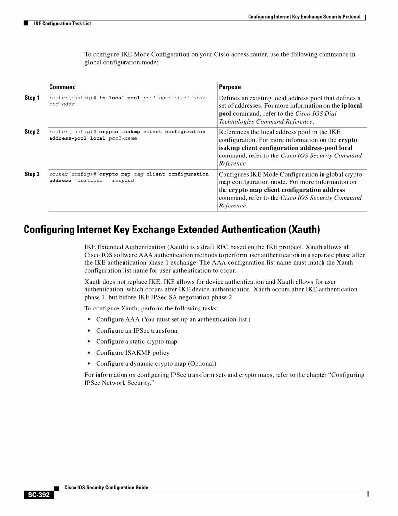
Configuring Internet Key Exchange Security ProtocolIKE Configuration Task List
SC-392Cisco IOS Security Configuration Guide
To configure IKE Mode Configuration on your Cisco access router, use the following commands in global configuration mode:
Configuring Internet Key Exchange Extended Authentication (Xauth)IKE Extended Authentication (Xauth) is a draft RFC based on the IKE protocol. Xauth allows all Cisco IOS software AAA authentication methods to perform user authentication in a separate phase after the IKE authentication phase 1 exchange. The AAA configuration list name must match the Xauth configuration list name for user authentication to occur.
Xauth does not replace IKE. IKE allows for device authentication and Xauth allows for user authentication, which occurs after IKE device authentication. Xauth occurs after IKE authentication phase 1, but before IKE IPSec SA negotiation phase 2.
To configure Xauth, perform the following tasks:
• Configure AAA (You must set up an authentication list.)
• Configure an IPSec transform
• Configure a static crypto map
• Configure ISAKMP policy
• Configure a dynamic crypto map (Optional)
For information on configuring IPSec transform sets and crypto maps, refer to the chapter “Configuring IPSec Network Security.”
Command Purpose
Step 1 router(config)# ip local pool pool-name start-addr end-addr
Defines an existing local address pool that defines a set of addresses. For more information on the ip local pool command, refer to the Cisco IOS Dial Technologies Command Reference.
Step 2 router(config)# crypto isakmp client configuration address-pool local pool-name
References the local address pool in the IKE configuration. For more information on the crypto isakmp client configuration address-pool local command, refer to the Cisco IOS Security Command Reference.
Step 3 router(config)# crypto map tag client configuration address [initiate | respond]
Configures IKE Mode Configuration in global crypto map configuration mode. For more information on the crypto map client configuration address command, refer to the Cisco IOS Security Command Reference.
Configuring Internet Key Exchange Security ProtocolIKE Configuration Task List
SC-393Cisco IOS Security Configuration Guide
To enable Xauth on a crypto map, perform the following task in crypto map configuration mode:
To verify that the Xauth feature is enabled, use the show crypto map command in EXEC mode. If the crypto map client authentication list command does not appear in the crypto map output, the Xauth feature is not enabled.
Configuring Tunnel Endpoint Discovery (TED)Tunnel Endpoint Discovery (TED) is an enhancement to the IPSec feature. Defining a dynamic crypto map allows you to be able to dynamically determine an IPSec peer; however, only the receiving router has this ability. With TED, the initiating router can dynamically determine an IPSec peer for secure IPSec communications.
Dynamic TED helps to simplify IPSec configuration on the individual routers within a large network. Each node has a simple configuration that defines the local network that the router is protecting and the required IPSec transforms.
To have a large, fully-meshed network without TED, each peer needs to have static crypto maps to every other peer in the network. For example, if there are 100 peers in a large, fully-meshed network, each router needs 99 static crypto maps for each of its peers. With TED, only a single dynamic crypto map with TED enabled is needed because the peer is discovered dynamically. Thus, static crypto maps do not need to be configured for each peer.
Note TED helps only in discovering peers; otherwise, TED does not function any differently than normal IPSec. TED does not improve the scalability of IPSec (in terms of performance or the number of peers or tunnels).
Figure 36 and the corresponding steps explain a sample TED network topology.
Command PurposeRouter(config)# crypto map map-name client authentication list list-name
Enables extended authentication (Xauth) on a crypto map.
Note After enabling Xauth, you should apply the crypto map on which Xauth is configured to the router interface.
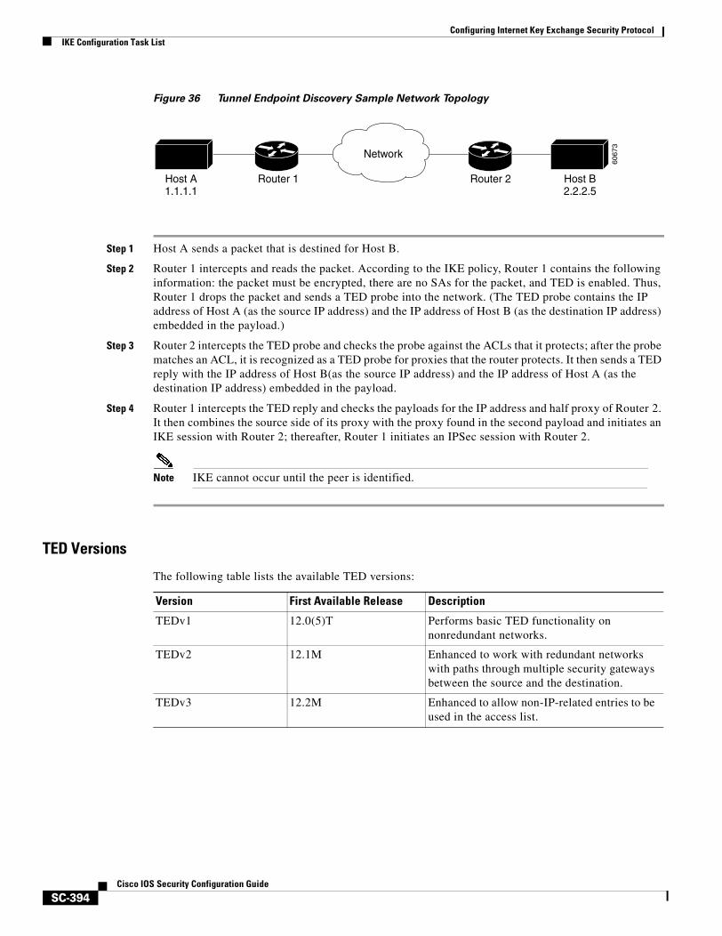
Configuring Internet Key Exchange Security ProtocolIKE Configuration Task List
SC-394Cisco IOS Security Configuration Guide
Figure 36 Tunnel Endpoint Discovery Sample Network Topology
Step 1 Host A sends a packet that is destined for Host B.
Step 2 Router 1 intercepts and reads the packet. According to the IKE policy, Router 1 contains the following information: the packet must be encrypted, there are no SAs for the packet, and TED is enabled. Thus, Router 1 drops the packet and sends a TED probe into the network. (The TED probe contains the IP address of Host A (as the source IP address) and the IP address of Host B (as the destination IP address) embedded in the payload.)
Step 3 Router 2 intercepts the TED probe and checks the probe against the ACLs that it protects; after the probe matches an ACL, it is recognized as a TED probe for proxies that the router protects. It then sends a TED reply with the IP address of Host B(as the source IP address) and the IP address of Host A (as the destination IP address) embedded in the payload.
Step 4 Router 1 intercepts the TED reply and checks the payloads for the IP address and half proxy of Router 2. It then combines the source side of its proxy with the proxy found in the second payload and initiates an IKE session with Router 2; thereafter, Router 1 initiates an IPSec session with Router 2.
Note IKE cannot occur until the peer is identified.
TED Versions
The following table lists the available TED versions:
Host A1.1.1.1
Router 1
Network
Host B2.2.2.5
Router 2
60673
Version First Available Release Description
TEDv1 12.0(5)T Performs basic TED functionality on nonredundant networks.
TEDv2 12.1M Enhanced to work with redundant networks with paths through multiple security gateways between the source and the destination.
TEDv3 12.2M Enhanced to allow non-IP-related entries to be used in the access list.

Configuring Internet Key Exchange Security ProtocolIKE Configuration Task List
SC-395Cisco IOS Security Configuration Guide
TED Restrictions
Tunnel Endpoint Discovery has the following restrictions:
• It is Cisco proprietary.
• It is available only on dynamic crypto maps. (The dynamic crypto map template is based on the dynamic crypto map performing peer discovery. Although there are no access-list restrictions on the dynamic crypto map template, the dynamic crypto map template should cover data sourced from the protected traffic and the receiving router using the any keyword. When using the any keyword, include explicit deny statements to exempt routing protocol traffic prior to entering the permit any command.)
• It is limited by the performance and scalability of limitation of IPSec on each individual platform.
Note Enabling TED slightly decreases the general scalability of IPSec because of the set-up overhead of peer discovery, which involves an additional “round-trip” of IKE messages (TED probe and reply). Although minimal, the additional memory used to store data structures during the peer discovery stage adversely affects the general scalability of IPSec.
• The IP addresses must be able to be routed within the network.
• The access list used in the crypto map for TED can only contain IP-related entries—TCP, UDP, or any other protocol cannot be used in the access list.
Note This restriction is no longer applicable in TEDv3.
To create a dynamic crypto map entry with Tunnel Endpoint Discovery (TED) configured, use the following commands, beginning in crypto-map configuration mode:
Command Purpose
Step 1 Router(config)# crypto dynamic-map dynamic-map-name dynamic-map-numberRouter (config-crypto-m)# set transform-set transform-set-name1 [transform-set-name2...transform-set-name6]Router (config-crypto-m)# match address access-list-idRouter (config-crypto-m)# set security-association lifetime seconds seconds
and/or
Router (config-crypto-m)# set security-association lifetime kilobytes kilobytesRouter (config-crypto-m)# set pfs [group1 | group2]Router (config-crypto-m)# exit
Configures a dynamic crypto map using the crypto dynamic-map command.
Note You must configure a match address; otherwise, the behavior is not secure, and you cannot enable TED because packets are sent in the clear (unencrypted.)
Step 2 Router(config)# crypto map map-name map-number ipsec-isakmp dynamic dynamic-map-name [discover]
Adds a dynamic crypto map to a crypto map set.
Enter the discover keyword on the dynamic crypto map to enable TED.
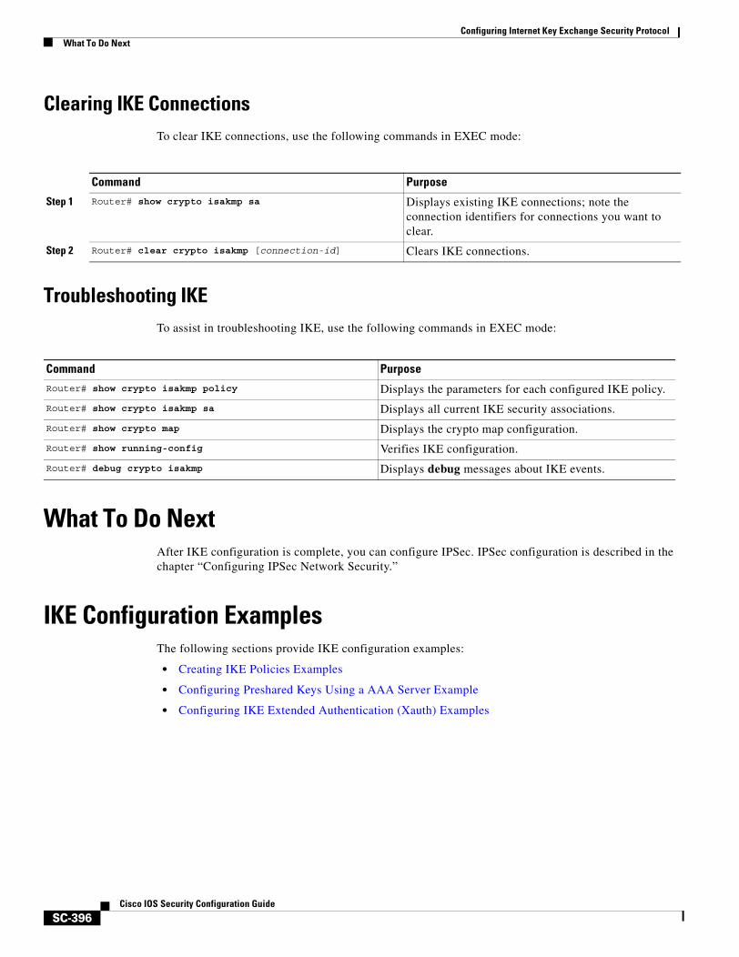
Configuring Internet Key Exchange Security ProtocolWhat To Do Next
SC-396Cisco IOS Security Configuration Guide
Clearing IKE ConnectionsTo clear IKE connections, use the following commands in EXEC mode:
Troubleshooting IKE To assist in troubleshooting IKE, use the following commands in EXEC mode:
What To Do NextAfter IKE configuration is complete, you can configure IPSec. IPSec configuration is described in the chapter “Configuring IPSec Network Security.”
IKE Configuration ExamplesThe following sections provide IKE configuration examples:
• Creating IKE Policies Examples
• Configuring Preshared Keys Using a AAA Server Example
• Configuring IKE Extended Authentication (Xauth) Examples
Command Purpose
Step 1 Router# show crypto isakmp sa Displays existing IKE connections; note the connection identifiers for connections you want to clear.
Step 2 Router# clear crypto isakmp [connection-id] Clears IKE connections.
Command Purpose
Router# show crypto isakmp policy Displays the parameters for each configured IKE policy.
Router# show crypto isakmp sa Displays all current IKE security associations.
Router# show crypto map Displays the crypto map configuration.
Router# show running-config Verifies IKE configuration.
Router# debug crypto isakmp Displays debug messages about IKE events.
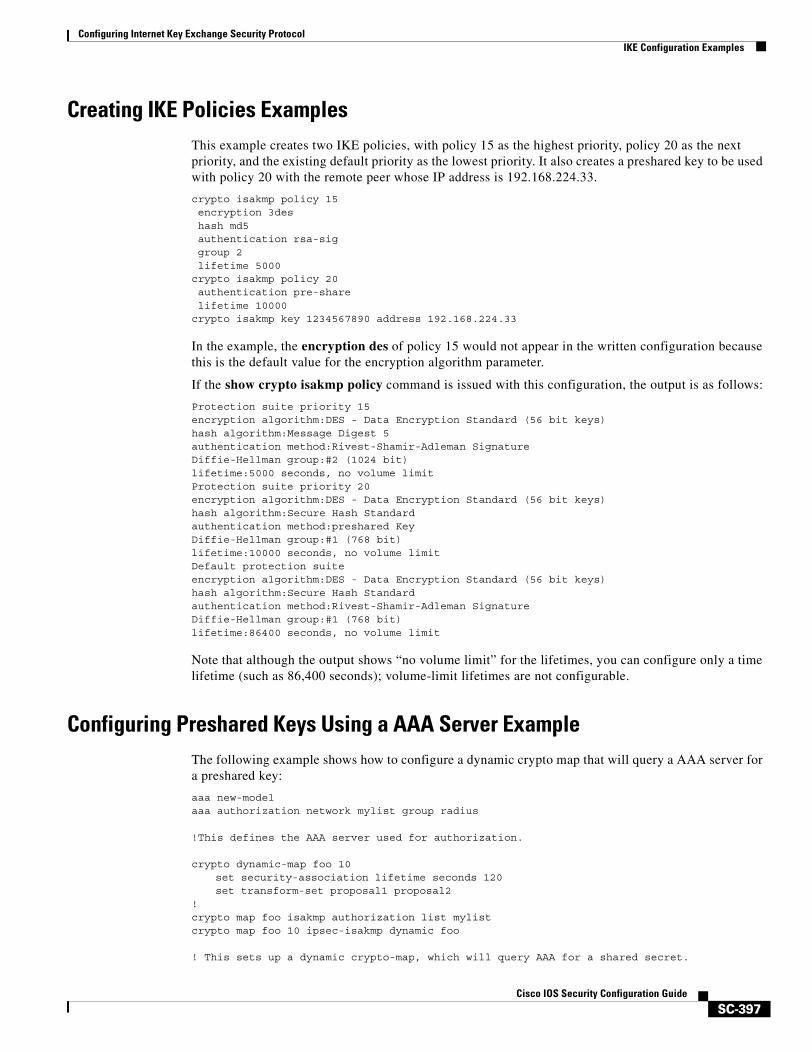
Configuring Internet Key Exchange Security ProtocolIKE Configuration Examples
SC-397Cisco IOS Security Configuration Guide
Creating IKE Policies ExamplesThis example creates two IKE policies, with policy 15 as the highest priority, policy 20 as the next priority, and the existing default priority as the lowest priority. It also creates a preshared key to be used with policy 20 with the remote peer whose IP address is 192.168.224.33.
crypto isakmp policy 15encryption 3deshash md5authentication rsa-siggroup 2lifetime 5000
crypto isakmp policy 20authentication pre-sharelifetime 10000
crypto isakmp key 1234567890 address 192.168.224.33
In the example, the encryption des of policy 15 would not appear in the written configuration because this is the default value for the encryption algorithm parameter.
If the show crypto isakmp policy command is issued with this configuration, the output is as follows:
Protection suite priority 15encryption algorithm:DES - Data Encryption Standard (56 bit keys)hash algorithm:Message Digest 5authentication method:Rivest-Shamir-Adleman SignatureDiffie-Hellman group:#2 (1024 bit)lifetime:5000 seconds, no volume limitProtection suite priority 20encryption algorithm:DES - Data Encryption Standard (56 bit keys)hash algorithm:Secure Hash Standardauthentication method:preshared KeyDiffie-Hellman group:#1 (768 bit)lifetime:10000 seconds, no volume limitDefault protection suiteencryption algorithm:DES - Data Encryption Standard (56 bit keys)hash algorithm:Secure Hash Standardauthentication method:Rivest-Shamir-Adleman SignatureDiffie-Hellman group:#1 (768 bit)lifetime:86400 seconds, no volume limit
Note that although the output shows “no volume limit” for the lifetimes, you can configure only a time lifetime (such as 86,400 seconds); volume-limit lifetimes are not configurable.
Configuring Preshared Keys Using a AAA Server Example The following example shows how to configure a dynamic crypto map that will query a AAA server for a preshared key:
aaa new-modelaaa authorization network mylist group radius
!This defines the AAA server used for authorization.
crypto dynamic-map foo 10set security-association lifetime seconds 120set transform-set proposal1 proposal2
!crypto map foo isakmp authorization list mylistcrypto map foo 10 ipsec-isakmp dynamic foo
! This sets up a dynamic crypto-map, which will query AAA for a shared secret.
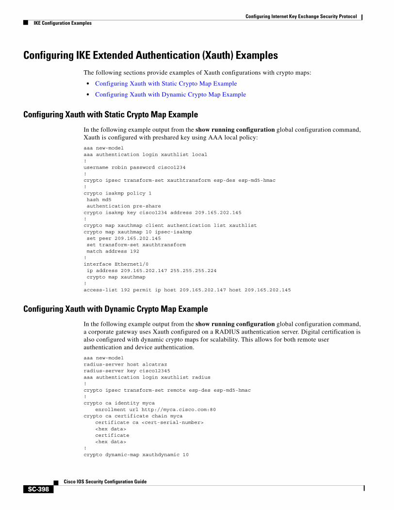
Configuring Internet Key Exchange Security ProtocolIKE Configuration Examples
SC-398Cisco IOS Security Configuration Guide
Configuring IKE Extended Authentication (Xauth) ExamplesThe following sections provide examples of Xauth configurations with crypto maps:
• Configuring Xauth with Static Crypto Map Example
• Configuring Xauth with Dynamic Crypto Map Example
Configuring Xauth with Static Crypto Map Example
In the following example output from the show running configuration global configuration command, Xauth is configured with preshared key using AAA local policy:
aaa new-model aaa authentication login xauthlist local ! username robin password cisco1234! crypto ipsec transform-set xauthtransform esp-des esp-md5-hmac ! crypto isakmp policy 1 hash md5 authentication pre-share crypto isakmp key cisco1234 address 209.165.202.145! crypto map xauthmap client authentication list xauthlistcrypto map xauthmap 10 ipsec-isakmp set peer 209.165.202.145 set transform-set xauthtransform match address 192 ! interface Ethernet1/0 ip address 209.165.202.147 255.255.255.224 crypto map xauthmap! access-list 192 permit ip host 209.165.202.147 host 209.165.202.145
Configuring Xauth with Dynamic Crypto Map Example
In the following example output from the show running configuration global configuration command, a corporate gateway uses Xauth configured on a RADIUS authentication server. Digital certification is also configured with dynamic crypto maps for scalability. This allows for both remote user authentication and device authentication.
aaa new-model radius-server host alcatrazradius-server key cisco12345aaa authentication login xauthlist radius ! crypto ipsec transform-set remote esp-des esp-md5-hmac ! crypto ca identity myca
enrollment url http://myca.cisco.com:80 crypto ca certificate chain myca
certificate ca <cert-serial-number> <hex data> certificate <hex data>
! crypto dynamic-map xauthdynamic 10

Configuring Internet Key Exchange Security ProtocolIKE Configuration Examples
SC-399Cisco IOS Security Configuration Guide
set transform-set xauthtransform! crypto map xauthmap client authentication list xauthlistcrypto map xauthmap 10 ipsec-isakmp dynamic xauthdynamic! interface Ethernet1/0
ip address 209.165.202.147 255.255.255.224 crypto map xauthmap

Configuring Internet Key Exchange Security ProtocolIKE Configuration Examples
SC-400Cisco IOS Security Configuration Guide
Other Security Features

SC-403Cisco IOS Security Configuration Guide
Configuring Passwords and Privileges
Using passwords and assigning privilege levels is a simple way of providing terminal access control in your network.
For a complete description of the commands used in this chapter, refer to the “Password and Privileges Commands” chapter in the Cisco IOS Security Command Reference. To locate documentation of other commands that appear in this chapter, use the command reference master index or search online.
To identify the hardware platform or software image information associated with a feature, use the Feature Navigator on Cisco.com to search for information about the feature or refer to the software release notes for a specific release. For more information, see the “Identifying Supported Platforms” section in the chapter “Using Cisco IOS Software.”
In This ChapterThis chapter includes the following sections:
• Protecting Access to Privileged EXEC Commands
• Configuring Multiple Privilege Levels
• Recovering a Lost Enable Password
• Recovering a Lost Line Password
• Configuring Identification Support
• Passwords and Privileges Configuration Examples
Protecting Access to Privileged EXEC CommandsThe following tasks provide a way to control access to the system configuration file and privileged EXEC (enable) commands:
• Setting or Changing a Static Enable Password
• Protecting Passwords with Enable Password and Enable Secret
• Setting or Changing a Line Password
• Encrypting Passwords
Configuring Passwords and PrivilegesProtecting Access to Privileged EXEC Commands
SC-404Cisco IOS Security Configuration Guide
Setting or Changing a Static Enable Password To set or change a static password that controls access to privileged EXEC (enable) mode, use the following command in global configuration mode:
For examples of how to define enable passwords for different privilege levels, see the section “Multiple Levels of Privileges Examples” at the end of this chapter.
Protecting Passwords with Enable Password and Enable SecretTo provide an additional layer of security, particularly for passwords that cross the network or are stored on a TFTP server, you can use either the enable password or enable secret commands. Both commands accomplish the same thing; that is, they allow you to establish an encrypted password that users must enter to access enable mode (the default), or any privilege level you specify.
We recommend that you use the enable secret command because it uses an improved encryption algorithm. Use the enable password command only if you boot an older image of the Cisco IOS software, or if you boot older boot ROMs that do not recognize the enable secret command.
If you configure the enable secret command, it takes precedence over the enable password command; the two commands cannot be in effect simultaneously.
To configure the router to require an enable password, use either of the following commands in global configuration mode:
Use either of these commands with the level option to define a password for a specific privilege level. After you specify the level and set a password, give the password only to users who need to have access at this level. Use the privilege level configuration command to specify commands accessible at various levels.
If you have the service password-encryption command enabled, the password you enter is encrypted. When you display it with the more system:running-config command, it is displayed in encrypted form.
If you specify an encryption type, you must provide an encrypted password—an encrypted password you copy from another router configuration.
Command Purpose
Router(config)# enable password password Establishes a new password or change an existing password for the privileged command level.
Command PurposeRouter(config)# enable password [level level] {password| encryption-type encrypted-password}
or
Router(config)# enable secret [level level] {password | encryption-type encrypted-password}
Establishes a password for a privilege command mode.
Specifies a secret password, saved using a non-reversible encryption method. (If enable password and enable secret are both set, users must enter the enable secret password.)
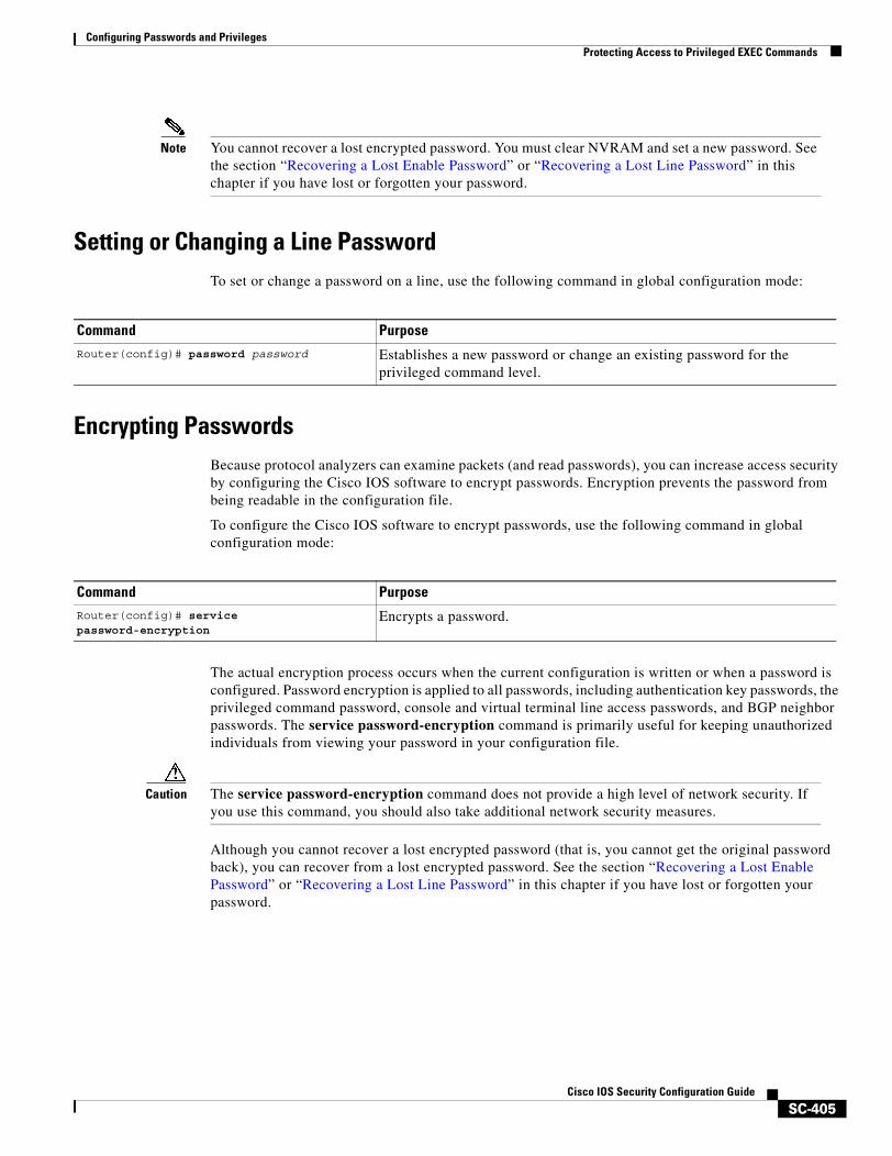
Configuring Passwords and PrivilegesProtecting Access to Privileged EXEC Commands
SC-405Cisco IOS Security Configuration Guide
Note You cannot recover a lost encrypted password. You must clear NVRAM and set a new password. See the section “Recovering a Lost Enable Password” or “Recovering a Lost Line Password” in this chapter if you have lost or forgotten your password.
Setting or Changing a Line Password To set or change a password on a line, use the following command in global configuration mode:
Encrypting PasswordsBecause protocol analyzers can examine packets (and read passwords), you can increase access security by configuring the Cisco IOS software to encrypt passwords. Encryption prevents the password from being readable in the configuration file.
To configure the Cisco IOS software to encrypt passwords, use the following command in global configuration mode:
The actual encryption process occurs when the current configuration is written or when a password is configured. Password encryption is applied to all passwords, including authentication key passwords, the privileged command password, console and virtual terminal line access passwords, and BGP neighbor passwords. The service password-encryption command is primarily useful for keeping unauthorized individuals from viewing your password in your configuration file.
Caution The service password-encryption command does not provide a high level of network security. If you use this command, you should also take additional network security measures.
Although you cannot recover a lost encrypted password (that is, you cannot get the original password back), you can recover from a lost encrypted password. See the section “Recovering a Lost Enable Password” or “Recovering a Lost Line Password” in this chapter if you have lost or forgotten your password.
Command Purpose
Router(config)# password password Establishes a new password or change an existing password for the privileged command level.
Command PurposeRouter(config)# service password-encryption
Encrypts a password.
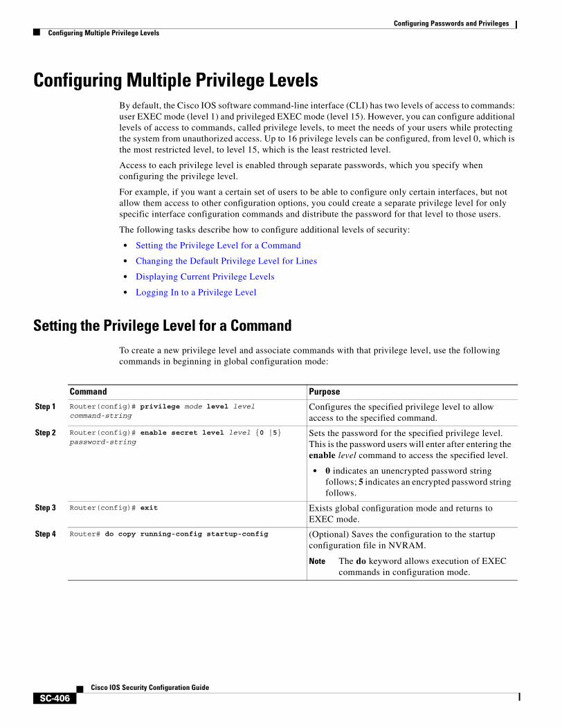
Configuring Passwords and PrivilegesConfiguring Multiple Privilege Levels
SC-406Cisco IOS Security Configuration Guide
Configuring Multiple Privilege LevelsBy default, the Cisco IOS software command-line interface (CLI) has two levels of access to commands: user EXEC mode (level 1) and privileged EXEC mode (level 15). However, you can configure additional levels of access to commands, called privilege levels, to meet the needs of your users while protecting the system from unauthorized access. Up to 16 privilege levels can be configured, from level 0, which is the most restricted level, to level 15, which is the least restricted level.
Access to each privilege level is enabled through separate passwords, which you specify when configuring the privilege level.
For example, if you want a certain set of users to be able to configure only certain interfaces, but not allow them access to other configuration options, you could create a separate privilege level for only specific interface configuration commands and distribute the password for that level to those users.
The following tasks describe how to configure additional levels of security:
• Setting the Privilege Level for a Command
• Changing the Default Privilege Level for Lines
• Displaying Current Privilege Levels
• Logging In to a Privilege Level
Setting the Privilege Level for a CommandTo create a new privilege level and associate commands with that privilege level, use the following commands in beginning in global configuration mode:
Command Purpose
Step 1 Router(config)# privilege mode level level command-string
Configures the specified privilege level to allow access to the specified command.
Step 2 Router(config)# enable secret level level {0 |5} password-string
Sets the password for the specified privilege level. This is the password users will enter after entering the enable level command to access the specified level.
• 0 indicates an unencrypted password string follows; 5 indicates an encrypted password string follows.
Step 3 Router(config)# exit Exists global configuration mode and returns to EXEC mode.
Step 4 Router# do copy running-config startup-config (Optional) Saves the configuration to the startup configuration file in NVRAM.
Note The do keyword allows execution of EXEC commands in configuration mode.
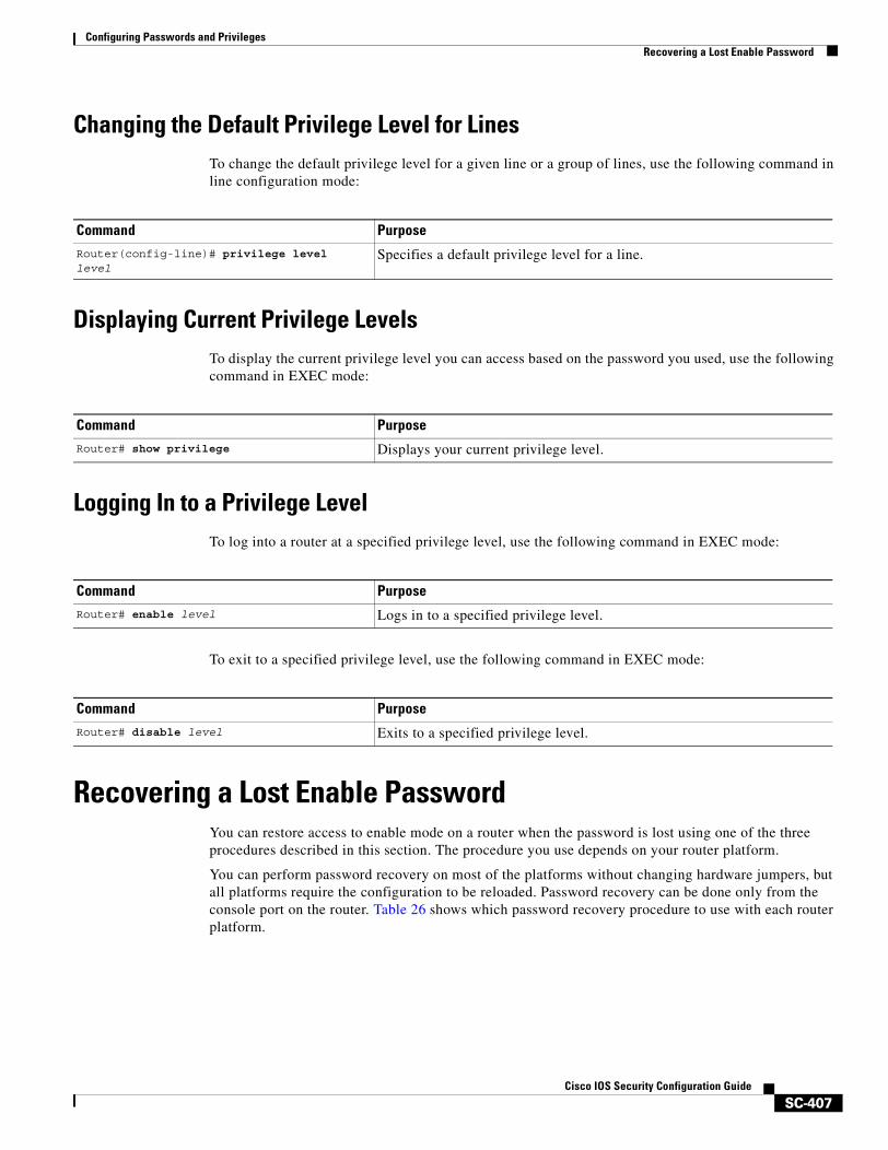
Configuring Passwords and PrivilegesRecovering a Lost Enable Password
SC-407Cisco IOS Security Configuration Guide
Changing the Default Privilege Level for LinesTo change the default privilege level for a given line or a group of lines, use the following command in line configuration mode:
Displaying Current Privilege LevelsTo display the current privilege level you can access based on the password you used, use the following command in EXEC mode:
Logging In to a Privilege LevelTo log into a router at a specified privilege level, use the following command in EXEC mode:
To exit to a specified privilege level, use the following command in EXEC mode:
Recovering a Lost Enable PasswordYou can restore access to enable mode on a router when the password is lost using one of the three procedures described in this section. The procedure you use depends on your router platform.
You can perform password recovery on most of the platforms without changing hardware jumpers, but all platforms require the configuration to be reloaded. Password recovery can be done only from the console port on the router. Table 26 shows which password recovery procedure to use with each router platform.
Command Purpose
Router(config-line)# privilege level level
Specifies a default privilege level for a line.
Command Purpose
Router# show privilege Displays your current privilege level.
Command Purpose
Router# enable level Logs in to a specified privilege level.
Command Purpose
Router# disable level Exits to a specified privilege level.
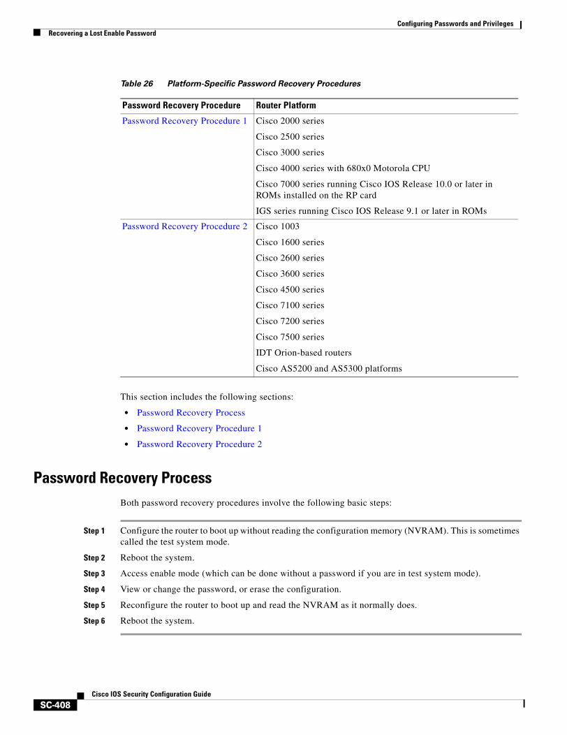
Configuring Passwords and PrivilegesRecovering a Lost Enable Password
SC-408Cisco IOS Security Configuration Guide
This section includes the following sections:
• Password Recovery Process
• Password Recovery Procedure 1
• Password Recovery Procedure 2
Password Recovery ProcessBoth password recovery procedures involve the following basic steps:
Step 1 Configure the router to boot up without reading the configuration memory (NVRAM). This is sometimes called the test system mode.
Step 2 Reboot the system.
Step 3 Access enable mode (which can be done without a password if you are in test system mode).
Step 4 View or change the password, or erase the configuration.
Step 5 Reconfigure the router to boot up and read the NVRAM as it normally does.
Step 6 Reboot the system.
Table 26 Platform-Specific Password Recovery Procedures
Password Recovery Procedure Router Platform
Password Recovery Procedure 1 Cisco 2000 series
Cisco 2500 series
Cisco 3000 series
Cisco 4000 series with 680x0 Motorola CPU
Cisco 7000 series running Cisco IOS Release 10.0 or later in ROMs installed on the RP card
IGS series running Cisco IOS Release 9.1 or later in ROMs
Password Recovery Procedure 2 Cisco 1003
Cisco 1600 series
Cisco 2600 series
Cisco 3600 series
Cisco 4500 series
Cisco 7100 series
Cisco 7200 series
Cisco 7500 series
IDT Orion-based routers
Cisco AS5200 and AS5300 platforms
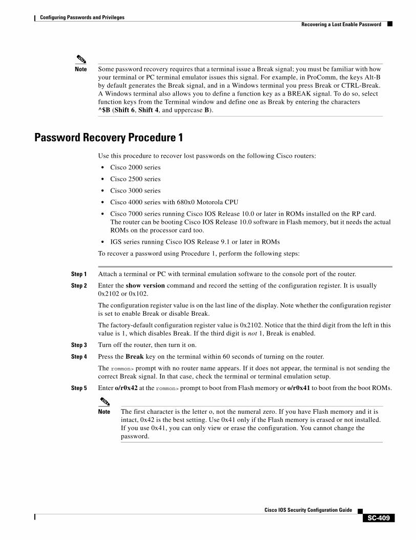
Configuring Passwords and PrivilegesRecovering a Lost Enable Password
SC-409Cisco IOS Security Configuration Guide
Note Some password recovery requires that a terminal issue a Break signal; you must be familiar with how your terminal or PC terminal emulator issues this signal. For example, in ProComm, the keys Alt-B by default generates the Break signal, and in a Windows terminal you press Break or CTRL-Break. A Windows terminal also allows you to define a function key as a BREAK signal. To do so, select function keys from the Terminal window and define one as Break by entering the characters ^$B (Shift 6, Shift 4, and uppercase B).
Password Recovery Procedure 1Use this procedure to recover lost passwords on the following Cisco routers:
• Cisco 2000 series
• Cisco 2500 series
• Cisco 3000 series
• Cisco 4000 series with 680x0 Motorola CPU
• Cisco 7000 series running Cisco IOS Release 10.0 or later in ROMs installed on the RP card.The router can be booting Cisco IOS Release 10.0 software in Flash memory, but it needs the actual ROMs on the processor card too.
• IGS series running Cisco IOS Release 9.1 or later in ROMs
To recover a password using Procedure 1, perform the following steps:
Step 1 Attach a terminal or PC with terminal emulation software to the console port of the router.
Step 2 Enter the show version command and record the setting of the configuration register. It is usually 0x2102 or 0x102.
The configuration register value is on the last line of the display. Note whether the configuration register is set to enable Break or disable Break.
The factory-default configuration register value is 0x2102. Notice that the third digit from the left in this value is 1, which disables Break. If the third digit is not 1, Break is enabled.
Step 3 Turn off the router, then turn it on.
Step 4 Press the Break key on the terminal within 60 seconds of turning on the router.
The rommon> prompt with no router name appears. If it does not appear, the terminal is not sending the correct Break signal. In that case, check the terminal or terminal emulation setup.
Step 5 Enter o/r0x42 at the rommon> prompt to boot from Flash memory or o/r0x41 to boot from the boot ROMs.
Note The first character is the letter o, not the numeral zero. If you have Flash memory and it is intact, 0x42 is the best setting. Use 0x41 only if the Flash memory is erased or not installed. If you use 0x41, you can only view or erase the configuration. You cannot change the password.
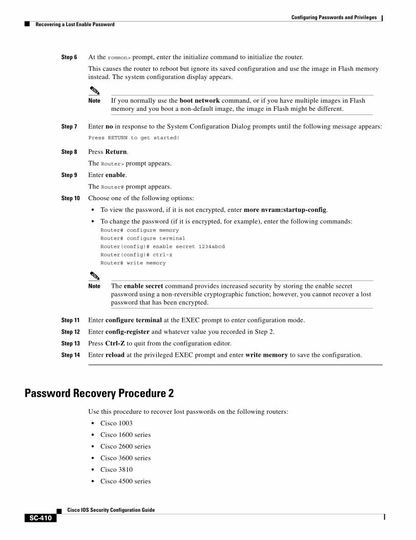
Configuring Passwords and PrivilegesRecovering a Lost Enable Password
SC-410Cisco IOS Security Configuration Guide
Step 6 At the rommon> prompt, enter the initialize command to initialize the router.
This causes the router to reboot but ignore its saved configuration and use the image in Flash memory instead. The system configuration display appears.
Note If you normally use the boot network command, or if you have multiple images in Flash memory and you boot a non-default image, the image in Flash might be different.
Step 7 Enter no in response to the System Configuration Dialog prompts until the following message appears:
Press RETURN to get started!
Step 8 Press Return.
The Router> prompt appears.
Step 9 Enter enable.
The Router# prompt appears.
Step 10 Choose one of the following options:
• To view the password, if it is not encrypted, enter more nvram:startup-config.
• To change the password (if it is encrypted, for example), enter the following commands:Router# configure memory
Router# configure terminal
Router(config)# enable secret 1234abcd
Router(config)# ctrl-z
Router# write memory
Note The enable secret command provides increased security by storing the enable secret password using a non-reversible cryptographic function; however, you cannot recover a lost password that has been encrypted.
Step 11 Enter configure terminal at the EXEC prompt to enter configuration mode.
Step 12 Enter config-register and whatever value you recorded in Step 2.
Step 13 Press Ctrl-Z to quit from the configuration editor.
Step 14 Enter reload at the privileged EXEC prompt and enter write memory to save the configuration.
Password Recovery Procedure 2Use this procedure to recover lost passwords on the following routers:
• Cisco 1003
• Cisco 1600 series
• Cisco 2600 series
• Cisco 3600 series
• Cisco 3810
• Cisco 4500 series
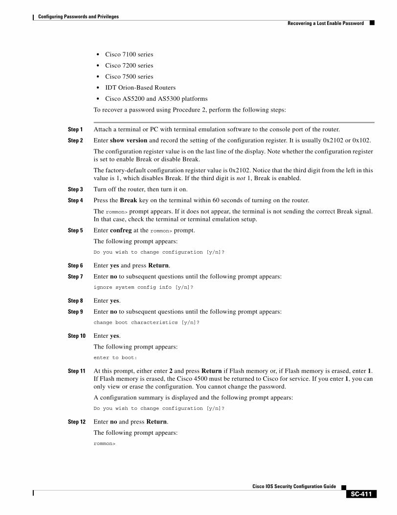
Configuring Passwords and PrivilegesRecovering a Lost Enable Password
SC-411Cisco IOS Security Configuration Guide
• Cisco 7100 series
• Cisco 7200 series
• Cisco 7500 series
• IDT Orion-Based Routers
• Cisco AS5200 and AS5300 platforms
To recover a password using Procedure 2, perform the following steps:
Step 1 Attach a terminal or PC with terminal emulation software to the console port of the router.
Step 2 Enter show version and record the setting of the configuration register. It is usually 0x2102 or 0x102.
The configuration register value is on the last line of the display. Note whether the configuration register is set to enable Break or disable Break.
The factory-default configuration register value is 0x2102. Notice that the third digit from the left in this value is 1, which disables Break. If the third digit is not 1, Break is enabled.
Step 3 Turn off the router, then turn it on.
Step 4 Press the Break key on the terminal within 60 seconds of turning on the router.
The rommon> prompt appears. If it does not appear, the terminal is not sending the correct Break signal. In that case, check the terminal or terminal emulation setup.
Step 5 Enter confreg at the rommon> prompt.
The following prompt appears:
Do you wish to change configuration [y/n]?
Step 6 Enter yes and press Return.
Step 7 Enter no to subsequent questions until the following prompt appears:
ignore system config info [y/n]?
Step 8 Enter yes.
Step 9 Enter no to subsequent questions until the following prompt appears:
change boot characteristics [y/n]?
Step 10 Enter yes.
The following prompt appears:
enter to boot:
Step 11 At this prompt, either enter 2 and press Return if Flash memory or, if Flash memory is erased, enter 1. If Flash memory is erased, the Cisco 4500 must be returned to Cisco for service. If you enter 1, you can only view or erase the configuration. You cannot change the password.
A configuration summary is displayed and the following prompt appears:
Do you wish to change configuration [y/n]?
Step 12 Enter no and press Return.
The following prompt appears:
rommon>
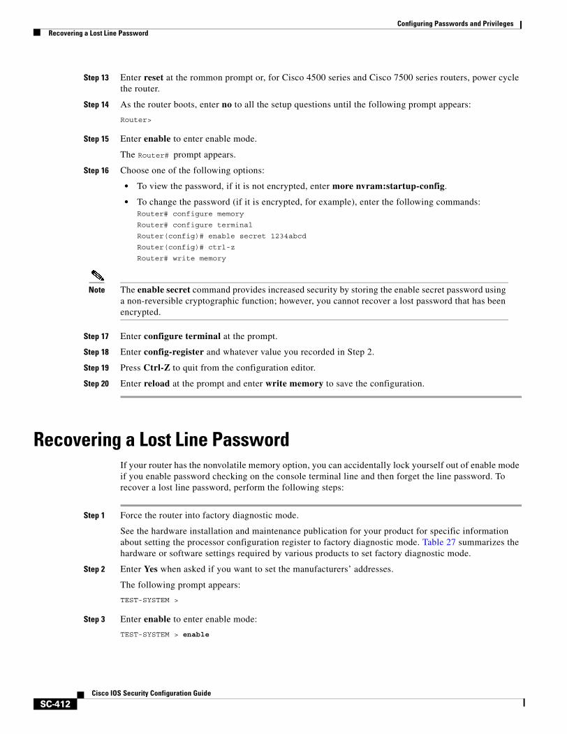
Configuring Passwords and PrivilegesRecovering a Lost Line Password
SC-412Cisco IOS Security Configuration Guide
Step 13 Enter reset at the rommon prompt or, for Cisco 4500 series and Cisco 7500 series routers, power cycle the router.
Step 14 As the router boots, enter no to all the setup questions until the following prompt appears:
Router>
Step 15 Enter enable to enter enable mode.
The Router# prompt appears.
Step 16 Choose one of the following options:
• To view the password, if it is not encrypted, enter more nvram:startup-config.
• To change the password (if it is encrypted, for example), enter the following commands:Router# configure memory
Router# configure terminal
Router(config)# enable secret 1234abcd
Router(config)# ctrl-z
Router# write memory
Note The enable secret command provides increased security by storing the enable secret password using a non-reversible cryptographic function; however, you cannot recover a lost password that has been encrypted.
Step 17 Enter configure terminal at the prompt.
Step 18 Enter config-register and whatever value you recorded in Step 2.
Step 19 Press Ctrl-Z to quit from the configuration editor.
Step 20 Enter reload at the prompt and enter write memory to save the configuration.
Recovering a Lost Line PasswordIf your router has the nonvolatile memory option, you can accidentally lock yourself out of enable mode if you enable password checking on the console terminal line and then forget the line password. To recover a lost line password, perform the following steps:
Step 1 Force the router into factory diagnostic mode.
See the hardware installation and maintenance publication for your product for specific information about setting the processor configuration register to factory diagnostic mode. Table 27 summarizes the hardware or software settings required by various products to set factory diagnostic mode.
Step 2 Enter Yes when asked if you want to set the manufacturers’ addresses.
The following prompt appears:
TEST-SYSTEM >
Step 3 Enter enable to enter enable mode:
TEST-SYSTEM > enable
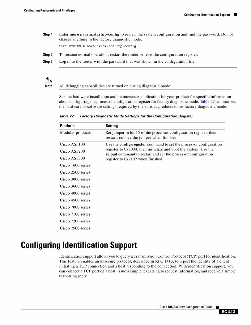
Configuring Passwords and PrivilegesConfiguring Identification Support
SC-413Cisco IOS Security Configuration Guide
Step 4 Enter more nvram:startup-config to review the system configuration and find the password. Do not change anything in the factory diagnostic mode.
TEST-SYSTEM # more nvram:startup-config
Step 5 To resume normal operation, restart the router or reset the configuration register.
Step 6 Log in to the router with the password that was shown in the configuration file.
Note All debugging capabilities are turned on during diagnostic mode.
See the hardware installation and maintenance publication for your product for specific information about configuring the processor configuration register for factory diagnostic mode. Table 27 summarizes the hardware or software settings required by the various products to set factory diagnostic mode.
Configuring Identification SupportIdentification support allows you to query a Transmission Control Protocol (TCP) port for identification. This feature enables an unsecure protocol, described in RFC 1413, to report the identity of a client initiating a TCP connection and a host responding to the connection. With identification support, you can connect a TCP port on a host, issue a simple text string to request information, and receive a simple text-string reply.
Table 27 Factory Diagnostic Mode Settings for the Configuration Register
Platform Setting
Modular products Set jumper in bit 15 of the processor configuration register, then restart; remove the jumper when finished.
Cisco AS5100
Cisco AS5200
Cisco AS5300
Cisco 1600 series
Cisco 2500 series
Cisco 3000 series
Cisco 3600 series
Cisco 4000 series
Cisco 4500 series
Cisco 7000 series
Cisco 7100 series
Cisco 7200 series
Cisco 7500 series
Use the config-register command to set the processor configuration register to 0x8000, then initialize and boot the system. Use the reload command to restart and set the processor configuration register to 0x2102 when finished.
Configuring Passwords and PrivilegesPasswords and Privileges Configuration Examples
SC-414Cisco IOS Security Configuration Guide
To configure identification support, use the following command in global configuration mode:
Passwords and Privileges Configuration ExamplesThe following sections provide password and privileges configuration examples:
• Multiple Levels of Privileges Examples
• Username Examples
Multiple Levels of Privileges ExamplesThis section provides examples of using multiple privilege levels to specify who can access different sets of commands. This section includes the following sections:
• Allowing Users to Clear Lines Examples
• Defining an Enable Password for System Operators Examples
• Disabling a Privilege Level Example
Allowing Users to Clear Lines Examples
If you want to allow users to clear lines, you can do either of the following:
• Change the privilege level for the clear and clear line commands to 1 or “ordinary user level,” as follows. This allows any user to clear lines.
privilege exec level 1 clear line
• Change the privilege level for the clear and clear line commands to level 2. To do so, use the privilege level global configuration command to specify privilege level 2. Then define an enable password for privilege level 2 and tell only those users who need to know what the password is.
enable password level 2 pswd2privilege exec level 2 clear line
Defining an Enable Password for System Operators Examples
In the following example, you define an enable password for privilege level 10 for system operators and make clear and debug commands available to anyone with that privilege level enabled.
enable password level 10 pswd10privilege exec level 10 clear lineprivilege exec level 10 debug ppp chapprivilege exec level 10 debug ppp errorprivilege exec level 10 debug ppp negotiation
The following example lowers the privilege level of the more system:running-config command and most configuration commands to operator level so that the configuration can be viewed by an operator. It leaves the privilege level of the configure command at 15. Individual configuration commands are
Command PurposeRouter(config)# ip identd Enables identification support.
Configuring Passwords and PrivilegesPasswords and Privileges Configuration Examples
SC-415Cisco IOS Security Configuration Guide
displayed in the more system:running-config output only if the privilege level for a command has been lowered to 10. Users are allowed to see only those commands that have a privilege level less than or equal to their current privilege level.
enable password level 15 pswd15privilege exec level 15 configureenable password level 10 pswd10privilege exec level 10 more system:running-config
Disabling a Privilege Level Example
In the following example, the show ip route command is set to privilege level 15. To keep all show ip and show commands from also being set to privilege level 15, these commands are specified to be privilege level 1.
privilege exec level 15 show ip routeprivilege exec level 1 show ipprivilege exec level 1 show
Username ExamplesThe following sample configuration sets up secret passwords on Routers A, B, and C, to enable the three routers to connect to each other.
To authenticate connections between Routers A and B, enter the following commands:
On Router A:
username B password a-b_secret
On Router B:
username A password a-b_secret
To authenticate connections between Routers A and C, enter the following commands:
On Router A:
username C password a-c_secret
On Router C:
username A password a-c_secret
To authenticate connections between Routers B and C, enter the following commands:
On Router B:
username C password b-c_secret
On Router C:
username B password b-c_secret
For example, suppose you enter the following command:
username bill password westward
The system displays this command as follows:
username bill password 7 21398211

Configuring Passwords and PrivilegesPasswords and Privileges Configuration Examples
SC-416Cisco IOS Security Configuration Guide
The encrypted version of the password is 21398211. The password was encrypted by the Cisco-defined encryption algorithm, as indicated by the “7.”
However, if you enter the following command, the system determines that the password is already encrypted and performs no encryption. Instead, it displays the command exactly as you entered it.
username bill password 7 21398211username bill password 7 21398211
SC-417Cisco IOS Security Configuration Guide
Neighbor Router Authentication: Overview and Guidelines
You can prevent your router from receiving fraudulent route updates by configuring neighbor router authentication.
This chapter describes neighbor router authentication as part of a total security plan. It describes what neighbor router authentication is, how it works, and why you should use it to increase your overall network security.
This chapter refers to neighbor router authentication as “neighbor authentication.” Neighbor router authentication is also sometimes called “route authentication.”
In This ChapterThis chapter describes the following topics:
• About Neighbor Authentication
• How Neighbor Authentication Works
• Key Management (Key Chains)
• Finding Neighbor Authentication Configuration Information
About Neighbor AuthenticationThis section contains the following sections:
• Benefits of Neighbor Authentication
• Protocols That Use Neighbor Authentication
• When to Configure Neighbor Authentication
Benefits of Neighbor AuthenticationWhen configured, neighbor authentication occurs whenever routing updates are exchanged between neighbor routers. This authentication ensures that a router receives reliable routing information from a trusted source.
Neighbor Router Authentication: Overview and GuidelinesHow Neighbor Authentication Works
SC-418Cisco IOS Security Configuration Guide
Without neighbor authentication, unauthorized or deliberately malicious routing updates could compromise the security of your network traffic. A security compromise could occur if an unfriendly party diverts or analyzes your network traffic. For example, an unauthorized router could send a fictitious routing update to convince your router to send traffic to an incorrect destination. This diverted traffic could be analyzed to learn confidential information of your organization, or merely used to disrupt your organization’s ability to effectively communicate using the network.
Neighbor authentication prevents any such fraudulent route updates from being received by your router.
Protocols That Use Neighbor AuthenticationNeighbor authentication can be configured for the following routing protocols:
• Border Gateway Protocol (BGP)
• DRP Server Agent
• Intermediate System-to-Intermediate System (IS-IS)
• IP Enhanced Interior Gateway Routing Protocol (IGRP)
• Open Shortest Path First (OSPF)
• Routing Information Protocol (RIP) version 2
When to Configure Neighbor AuthenticationYou should configure any router for neighbor authentication if that router meets all of these conditions:
• The router uses any of the routing protocols previously mentioned.
• It is conceivable that the router might receive a false route update.
• If the router were to receive a false route update, your network might be compromised.
• If you configure a router for neighbor authentication, you also need to configure the neighbor router for neighbor authentication.
How Neighbor Authentication WorksWhen neighbor authentication has been configured on a router, the router authenticates the source of each routing update packet that it receives. This is accomplished by the exchange of an authenticating key (sometimes referred to as a password) that is known to both the sending and the receiving router.
There are two types of neighbor authentication used: plain text authentication and Message Digest Algorithm Version 5 (MD5) authentication. Both forms work in the same way, with the exception that MD5 sends a “message digest” instead of the authenticating key itself. The message digest is created using the key and a message, but the key itself is not sent, preventing it from being read while it is being transmitted. Plain text authentication sends the authenticating key itself over the wire.
Note Note that plain text authentication is not recommended for use as part of your security strategy. Its primary use is to avoid accidental changes to the routing infrastructure. Using MD5 authentication, however, is a recommended security practice.
Neighbor Router Authentication: Overview and GuidelinesHow Neighbor Authentication Works
SC-419Cisco IOS Security Configuration Guide
Caution As with all keys, passwords, and other security secrets, it is imperative that you closely guard authenticating keys used in neighbor authentication. The security benefits of this feature are reliant upon your keeping all authenticating keys confidential. Also, when performing router management tasks via Simple Network Management Protocol (SNMP), do not ignore the risk associated with sending keys using non-encrypted SNMP.
This section includes the following sections:
• Plain Text Authentication
• MD5 Authentication
Plain Text AuthenticationEach participating neighbor router must share an authenticating key. This key is specified at each router during configuration. Multiple keys can be specified with some protocols; each key must then be identified by a key number.
In general, when a routing update is sent, the following authentication sequence occurs:
Step 1 A router sends a routing update with a key and the corresponding key number to the neighbor router. In protocols that can have only one key, the key number is always zero.
Step 2 The receiving (neighbor) router checks the received key against the same key stored in its own memory.
Step 3 If the two keys match, the receiving router accepts the routing update packet. If the two keys do not match, the routing update packet is rejected.
These protocols use plain text authentication:
• DRP Server Agent
• IS-IS
• OSPF
• RIP version 2
MD5 AuthenticationMD5 authentication works similarly to plain text authentication, except that the key is never sent over the wire. Instead, the router uses the MD5 algorithm to produce a “message digest” of the key (also called a “hash”). The message digest is then sent instead of the key itself. This ensures that nobody can eavesdrop on the line and learn keys during transmission.
These protocols use MD5 authentication:
• OSPF
• RIP version 2
• BGP
• IP Enhanced IGRP
Neighbor Router Authentication: Overview and GuidelinesKey Management (Key Chains)
SC-420Cisco IOS Security Configuration Guide
Key Management (Key Chains)You can configure key chains for these IP routing protocols:
• RIP version 2
• IP Enhanced IGRP
• DRP Server Agent
These routing protocols offer the additional function of managing keys by using key chains. When you configure a key chain, you specify a series of keys with lifetimes, and the Cisco IOS software rotates through each of these keys. This decreases the likelihood that keys will be compromised.
Each key definition within the key chain must specify a time interval for which that key will be activated (its “lifetime”). Then, during a given key’s lifetime, routing update packets are sent with this activated key. Keys cannot be used during time periods for which they are not activated. Therefore, it is recommended that for a given key chain, key activation times overlap to avoid any period of time for which no key is activated. If a time period occurs during which no key is activated, neighbor authentication cannot occur, and therefore routing updates will fail.
Multiple key chains can be specified.
Note that the router needs to know the time to be able to rotate through keys in synchronization with the other participating routers, so that all routers are using the same key at the same moment. Refer to the Network Time Protocol (NTP) and calendar commands in the “Performing Basic System Management” chapter of the Cisco IOS Configuration Fundamentals Configuration Guide for information about configuring time at your router.
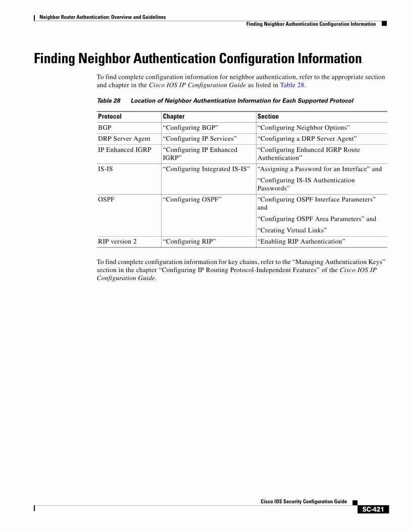
Neighbor Router Authentication: Overview and GuidelinesFinding Neighbor Authentication Configuration Information
SC-421Cisco IOS Security Configuration Guide
Finding Neighbor Authentication Configuration InformationTo find complete configuration information for neighbor authentication, refer to the appropriate section and chapter in the Cisco IOS IP Configuration Guide as listed in Table 28.
To find complete configuration information for key chains, refer to the “Managing Authentication Keys” section in the chapter “Configuring IP Routing Protocol-Independent Features” of the Cisco IOS IP Configuration Guide.
Table 28 Location of Neighbor Authentication Information for Each Supported Protocol
Protocol Chapter Section
BGP “Configuring BGP” “Configuring Neighbor Options”
DRP Server Agent “Configuring IP Services” “Configuring a DRP Server Agent”
IP Enhanced IGRP “Configuring IP Enhanced IGRP”
“Configuring Enhanced IGRP Route Authentication”
IS-IS “Configuring Integrated IS-IS” “Assigning a Password for an Interface” and
“Configuring IS-IS Authentication Passwords”
OSPF “Configuring OSPF” “Configuring OSPF Interface Parameters” and
“Configuring OSPF Area Parameters” and
“Creating Virtual Links”
RIP version 2 “Configuring RIP” “Enabling RIP Authentication”

Neighbor Router Authentication: Overview and GuidelinesFinding Neighbor Authentication Configuration Information
SC-422Cisco IOS Security Configuration Guide

SC-423Cisco IOS Security Configuration Guide
Configuring IP Security Options
Cisco provides IP Security Option (IPSO) support as described in RFC 1108. Cisco’s implementation is only minimally compliant with RFC 1108 because the Cisco IOS software only accepts and generates a 4-byte IPSO.
IPSO is generally used to comply with the U.S. government’s Department of Defense security policy.
For a complete description of IPSO commands, refer to the chapter “IP Security Options Commands” of the Cisco IOS Security Command Reference. To locate documentation of other commands that appear in this chapter, use the command reference master index or search online.
To identify the hardware platform or software image information associated with a feature, use the Feature Navigator on Cisco.com to search for information about the feature or refer to the software release notes for a specific release. For more information, see the “Identifying Supported Platforms” section in the chapter “Using Cisco IOS Software.”
In This ChapterThis chapter describes how to configure IPSO for both the basic and extended security options described in RFC 1108. This chapter also describes how to configure auditing for IPSO. This chapter includes the following sections:
• IPSO Configuration Task List
• IPSO Configuration Examples
IPSO Configuration Task ListThis section describes the following configuration tasks:
• Configuring Basic IP Security Options
• Configuring Extended IP Security Options
• Configuring the DNSIX Audit Trail Facility

Configuring IP Security OptionsIPSO Configuration Task List
SC-424Cisco IOS Security Configuration Guide
Configuring Basic IP Security OptionsCisco’s basic IPSO support provides the following features:
• Defines security level on a per-interface basis
• Defines single-level or multilevel interfaces
• Provides a label for incoming packets
• Strips labels on a per-interface basis
• Reorders options to put any basic security options first
To configure basic IPSO, complete the tasks in the following sections:
• Enabling IPSO and Setting the Security Classifications
• Specifying How IP Security Options Are Processed
Enabling IPSO and Setting the Security Classifications
To enable IPSO and set security classifications on an interface, use either of the following commands in interface configuration mode:
Use the no ip security command to reset an interface to its default state.
Specifying How IP Security Options Are Processed
To specify how IP security options are processed, use any of the following optional commands in interface configuration mode:
Command PurposeRouter(config-if)# ip security dedicated level authority [authority...]
Sets an interface to the requested IPSO classification and authorities.
Router(config-if)# ip security multilevel level1 [authority1...] to level2 authority2 [authority2...]
Sets an interface to the requested IPSO range of classifications and authorities.
Command PurposeRouter(config-if)# ip security ignore-authorities Enables an interface to ignore the authorities field of all incoming
packets.
Router(config-if)# ip security implicit-labelling [level authority [authority...]]
Classifies packets that have no IPSO with an implicit security label.
Router(config-if)# ip security extended-allowed Accepts packets on an interface that has an extended security option present.
Router(config-if)# ip security ad Ensures that all packets leaving the router on an interface contain a basic security option.
Router(config-if)# ip security strip Removes any basic security option that might be present on a packet leaving the router through an interface.
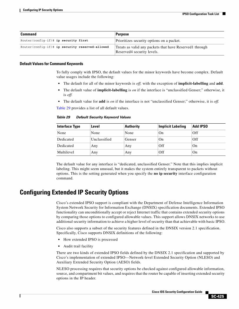
Configuring IP Security OptionsIPSO Configuration Task List
SC-425Cisco IOS Security Configuration Guide
Default Values for Command Keywords
To fully comply with IPSO, the default values for the minor keywords have become complex. Default value usages include the following:
• The default for all of the minor keywords is off, with the exception of implicit-labelling and add.
• The default value of implicit-labelling is on if the interface is “unclassified Genser;” otherwise, it is off.
• The default value for add is on if the interface is not “unclassified Genser;” otherwise, it is off.
Table 29 provides a list of all default values.
The default value for any interface is “dedicated, unclassified Genser.” Note that this implies implicit labeling. This might seem unusual, but it makes the system entirely transparent to packets without options. This is the setting generated when you specify the no ip security interface configuration command.
Configuring Extended IP Security OptionsCisco’s extended IPSO support is compliant with the Department of Defense Intelligence Information System Network Security for Information Exchange (DNSIX) specification documents. Extended IPSO functionality can unconditionally accept or reject Internet traffic that contains extended security options by comparing those options to configured allowable values. This support allows DNSIX networks to use additional security information to achieve a higher level of security than that achievable with basic IPSO.
Cisco also supports a subset of the security features defined in the DNSIX version 2.1 specification. Specifically, Cisco supports DNSIX definitions of the following:
• How extended IPSO is processed
• Audit trail facility
There are two kinds of extended IPSO fields defined by the DNSIX 2.1 specification and supported by Cisco’s implementation of extended IPSO—Network-level Extended Security Option (NLESO) and Auxiliary Extended Security Option (AESO) fields.
NLESO processing requires that security options be checked against configured allowable information, source, and compartment bit values, and requires that the router be capable of inserting extended security options in the IP header.
Router(config-if)# ip security first Prioritizes security options on a packet.
Router(config-if)# ip security reserved-allowed Treats as valid any packets that have Reserved1 through Reserved4 security levels.
Command Purpose
Table 29 Default Security Keyword Values
Interface Type Level Authority Implicit Labeling Add IPSO
None None None On Off
Dedicated Unclassified Genser On Off
Dedicated Any Any Off On
Multilevel Any Any Off On
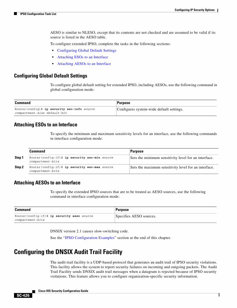
Configuring IP Security OptionsIPSO Configuration Task List
SC-426Cisco IOS Security Configuration Guide
AESO is similar to NLESO, except that its contents are not checked and are assumed to be valid if its source is listed in the AESO table.
To configure extended IPSO, complete the tasks in the following sections:
• Configuring Global Default Settings
• Attaching ESOs to an Interface
• Attaching AESOs to an Interface
Configuring Global Default Settings
To configure global default setting for extended IPSO, including AESOs, use the following command in global configuration mode:
Attaching ESOs to an Interface
To specify the minimum and maximum sensitivity levels for an interface, use the following commands in interface configuration mode:
Attaching AESOs to an Interface
To specify the extended IPSO sources that are to be treated as AESO sources, use the following command in interface configuration mode:
DNSIX version 2.1 causes slow-switching code.
See the “IPSO Configuration Examples” section at the end of this chapter.
Configuring the DNSIX Audit Trail FacilityThe audit trail facility is a UDP-based protocol that generates an audit trail of IPSO security violations. This facility allows the system to report security failures on incoming and outgoing packets. The Audit Trail Facility sends DNSIX audit trail messages when a datagram is rejected because of IPSO security violations. This feature allows you to configure organization-specific security information.
Command PurposeRouter(config)# ip security eso-info source compartment-size default-bit
Configures system-wide default settings.
Command Purpose
Step 1 Router(config-if)# ip security eso-min source compartment-bits
Sets the minimum sensitivity level for an interface.
Step 2 Router(config-if)# ip security eso-max source compartment-bits
Sets the maximum sensitivity level for an interface.
Command Purpose
Router(config-if)# ip security aeso source compartment-bits
Specifies AESO sources.
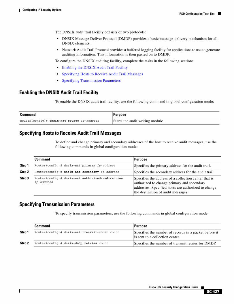
Configuring IP Security OptionsIPSO Configuration Task List
SC-427Cisco IOS Security Configuration Guide
The DNSIX audit trail facility consists of two protocols:
• DNSIX Message Deliver Protocol (DMDP) provides a basic message-delivery mechanism for all DNSIX elements.
• Network Audit Trail Protocol provides a buffered logging facility for applications to use to generate auditing information. This information is then passed on to DMDP.
To configure the DNSIX auditing facility, complete the tasks in the following sections:
• Enabling the DNSIX Audit Trail Facility
• Specifying Hosts to Receive Audit Trail Messages
• Specifying Transmission Parameters
Enabling the DNSIX Audit Trail Facility
To enable the DNSIX audit trail facility, use the following command in global configuration mode:
Specifying Hosts to Receive Audit Trail Messages
To define and change primary and secondary addresses of the host to receive audit messages, use the following commands in global configuration mode:
Specifying Transmission Parameters
To specify transmission parameters, use the following commands in global configuration mode:
Command PurposeRouter(config)# dnsix-nat source ip-address Starts the audit writing module.
Command Purpose
Step 1 Router(config)# dnsix-nat primary ip-address Specifies the primary address for the audit trail.
Step 2 Router(config)# dnsix-nat secondary ip-address Specifies the secondary address for the audit trail.
Step 3 Router(config)# dnsix-nat authorized-redirection ip-address
Specifies the address of a collection center that is authorized to change primary and secondary addresses. Specified hosts are authorized to change the destination of audit messages.
Command Purpose
Step 1 Router(config)# dnsix-nat transmit-count count Specifies the number of records in a packet before it is sent to a collection center.
Step 2 Router(config)# dnsix-dmdp retries count Specifies the number of transmit retries for DMDP.
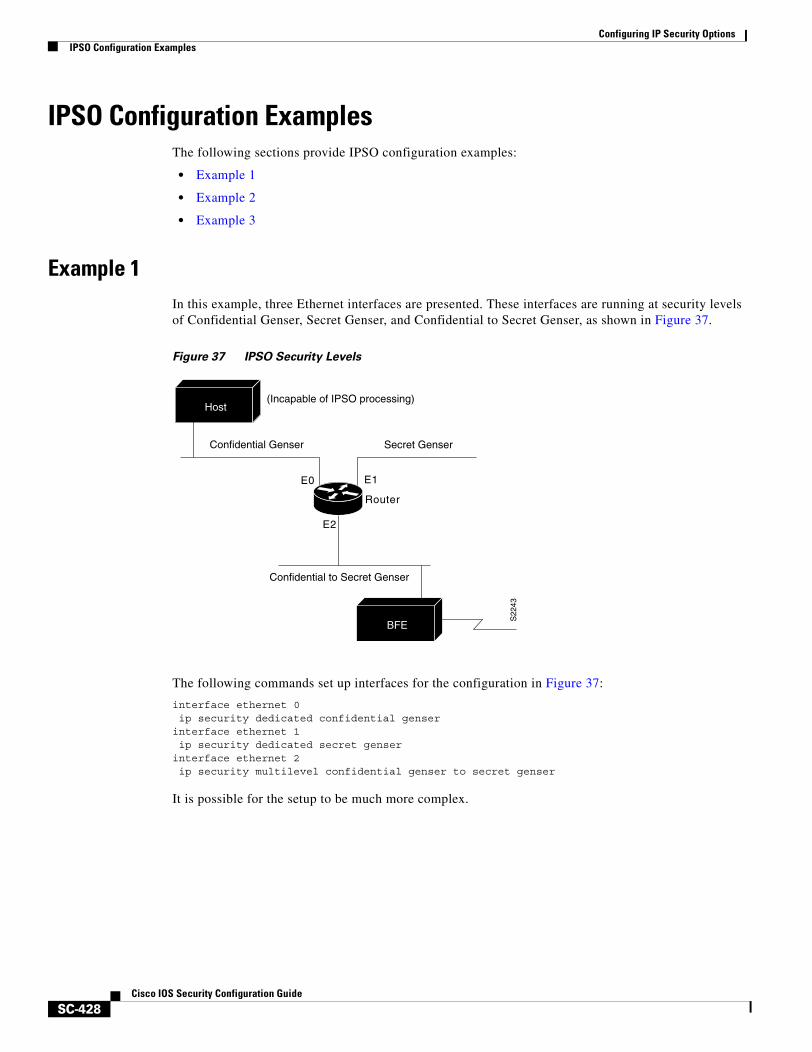
Configuring IP Security OptionsIPSO Configuration Examples
SC-428Cisco IOS Security Configuration Guide
IPSO Configuration ExamplesThe following sections provide IPSO configuration examples:
• Example 1
• Example 2
• Example 3
Example 1In this example, three Ethernet interfaces are presented. These interfaces are running at security levels of Confidential Genser, Secret Genser, and Confidential to Secret Genser, as shown in Figure 37.
Figure 37 IPSO Security Levels
The following commands set up interfaces for the configuration in Figure 37:
interface ethernet 0ip security dedicated confidential genser
interface ethernet 1ip security dedicated secret genser
interface ethernet 2ip security multilevel confidential genser to secret genser
It is possible for the setup to be much more complex.
Router
Confidential Genser
E0 E1
Secret Genser
S22
43
Confidential to Secret Genser
E2
Host
BFE
(Incapable of IPSO processing)
Configuring IP Security OptionsIPSO Configuration Examples
SC-429Cisco IOS Security Configuration Guide
Example 2In the following example, there are devices on Ethernet 0 that cannot generate a security option, and so must accept packets without a security option. These hosts do not understand security options; therefore, never place one on such interfaces. Furthermore, there are hosts on the other two networks that are using the extended security option to communicate information, so you must allow these to pass through the system. Finally, there also is a host (a Blacker Front End; see the “Configuring X.25 and LABP” chapter of the Cisco IOS Wide-Area Networking Configuration Guide for more information about Blacker emergency mode) on Ethernet 2 that requires the security option to be the first option present, and this condition also must be specified. The new configuration follows.
interface ethernet 0ip security dedicated confidential genserip security implicit-labellingip security strip
interface ethernet 1ip security dedicated secret genserip security extended-allowed
!interface ethernet 2ip security multilevel confidential genser to secret genserip security extended-allowedip security first
Example 3This example shows how to configure a Cisco router with HP-UX CMW DNSIX hosts. The following commands should be configured on each LAN interface of the router for two DNSIX hosts to communicate:
ip security multilevel unclassified nsa to top secret nsaip security extended allowed
DNSIX hosts do not need to know the router’s IP addresses, and DNSIX hosts do not need to set up M6RHDB entries for the routers.

Configuring IP Security OptionsIPSO Configuration Examples
SC-430Cisco IOS Security Configuration Guide
SC-431Cisco IOS Security Configuration Guide
Configuring Unicast Reverse Path Forwarding
This chapter describes the Unicast Reverse Path Forwarding (Unicast RPF) feature. The Unicast RPF feature helps to mitigate problems that are caused by malformed or forged IP source addresses that are passing through a router.
For a complete description of the Unicast RPF commands in this chapter, refer to the chapter “Unicast Reverse Path Forwarding Commands” of the Cisco IOS Security Command Reference. To locate documentation of other commands that appear in this chapter, use the command reference master index or search online.
To identify the hardware platform or software image information associated with a feature, use the Feature Navigator on Cisco.com to search for information about the feature or refer to the software release notes for a specific release. For more information, see the “Identifying Supported Platforms” section in the chapter “Using Cisco IOS Software.”
In This ChapterThis chapter has the following sections:
• About Unicast Reverse Path Forwarding
• Unicast RPF Configuration Task List
• Troubleshooting Tips
• Monitoring and Maintaining Unicast RPF
• Unicast RPF Configuration Examples
About Unicast Reverse Path ForwardingThe Unicast RPF feature helps to mitigate problems that are caused by the introduction of malformed or forged (spoofed) IP source addresses into a network by discarding IP packets that lack a verifiable IP source address. For example, a number of common types of denial-of-service (DoS) attacks, including Smurf and Tribe Flood Network (TFN), can take advantage of forged or rapidly changing source IP addresses to allow attackers to thwart efforts to locate or filter the attacks. For Internet service providers (ISPs) that provide public access, Unicast RPF deflects such attacks by forwarding only packets that have source addresses that are valid and consistent with the IP routing table. This action protects the network of the ISP, its customer, and the rest of the Internet.
Configuring Unicast Reverse Path ForwardingAbout Unicast Reverse Path Forwarding
SC-432Cisco IOS Security Configuration Guide
This section covers the following information:
• How Unicast RPF Works
• Implementing Unicast RPF
• Restrictions
• Related Features and Technologies
• Prerequisites to Configuring Unicast RPF
How Unicast RPF WorksWhen Unicast RPF is enabled on an interface, the router examines all packets received as input on that interface to make sure that the source address and source interface appear in the routing table and match the interface on which the packet was received. This “look backwards” ability is available only when Cisco express forwarding (CEF) is enabled on the router, because the lookup relies on the presence of the Forwarding Information Base (FIB). CEF generates the FIB as part of its operation.
Note Unicast RPF is an input function and is applied only on the input interface of a router at the upstream end of a connection.
Unicast RPF checks to see if any packet received at a router interface arrives on the best return path (return route) to the source of the packet. Unicast RPF does this by doing a reverse lookup in the CEF table. If the packet was received from one of the best reverse path routes, the packet is forwarded as normal. If there is no reverse path route on the same interface from which the packet was received, it might mean that the source address was modified. If Unicast RPF does not find a reverse path for the packet, the packet is dropped or forwarded, depending on whether an access control list (ACL) is specified in the ip verify unicast reverse-path interface configuration command.
Note With Unicast RPF, all equal-cost “best” return paths are considered valid. This means that Unicast RPF works in cases where multiple return paths exist, provided that each path is equal to the others in terms of the routing cost (number of hops, weights, and so on) and as long as the route is in the FIB. Unicast RPF also functions where EIGRP variants are being used and unequal candidate paths back to the source IP address exist.
When a packet is received at the interface where Unicast RPF and ACLs have been configured, the following actions occur:
Step 1 Input ACLs configured on the inbound interface are checked.
Step 2 Unicast RPF checks to see if the packet has arrived on the best return path to the source, which it does by doing a reverse lookup in the FIB table.
Step 3 CEF table (FIB) lookup is carried out for packet forwarding.
Step 4 Output ACLs are checked on the outbound interface.
Step 5 The packet is forwarded.
This section provides information about Unicast RPF enhancements:
• Access Control Lists and Logging
• Per-Interface Statistics

Configuring Unicast Reverse Path ForwardingAbout Unicast Reverse Path Forwarding
SC-433Cisco IOS Security Configuration Guide
Access Control Lists and Logging
If an ACL is specified in the command, then when (and only when) a packet fails the Unicast RPF check, the ACL is checked to see if the packet should be dropped (using a deny statement in the ACL) or forwarded (using a permit statement in the ACL). Whether a packet is dropped or forwarded, the packet is counted in the global IP traffic statistics for Unicast RPF drops and in the interface statistics for Unicast RPF.
If no ACL is specified in the Unicast RPF command, the router drops the forged or malformed packet immediately and no ACL logging occurs. The router and interface Unicast RPF counters are updated.
Unicast RPF events can be logged by specifying the logging option for the ACL entries used by the Unicast RPF command. Using the log information, administrators can see what source addresses are being used in the attack, the time the packets arrived at the interface, and so on.
Caution Logging requires CPU and memory resources. Logging Unicast RPF events for attacks having a high rate of forged packets can degrade the performance of the router.
Per-Interface Statistics
Each time a packet is dropped or forwarded at an interface, that information is counted two ways: globally on the router and at each interface where you have applied Unicast RPF. Global statistics on dropped packets provide information about potential attacks on the network; however, these global statistics do not help to specify which interface is the source of the attack.
Per-interface statistics allow network administrators to track two types of information about malformed packets: Unicast RPF drops and Unicast RPF suppressed drops. Statistics on the number of packets that Unicast RPF drops help to identify the interface that is the entry point of the attack. The Unicast RPF drop count tracks the number of drops at the interface. The Unicast RPF suppressed drop count tracks the number of packets that failed the Unicast RPF check but were forwarded because of the permit permission set up in the ACL. Using the drop count and suppressed drop count statistics, a network administrator can takes steps to isolate the attack at a specific interface.
Note Judicious use of ACL logging can further identify the address or addresses that are being dropped by Unicast RPF.
Figure 38 illustrates how Unicast RPF and CEF work together to validate IP source addresses by verifying packet return paths. In this example, a customer has sent a packet having a source address of 192.168.1.1 from interface FDDI 2/0/0. Unicast RPF checks the FIB to see if 192.168.1.1 has a path to FDDI 2/0/0. If there is a matching path, the packet is forwarded. If there is no matching path, the packet is dropped.
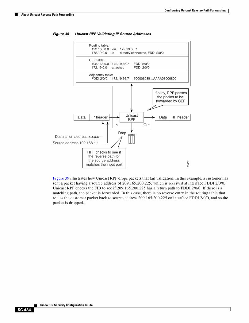
Configuring Unicast Reverse Path ForwardingAbout Unicast Reverse Path Forwarding
SC-434Cisco IOS Security Configuration Guide
Figure 38 Unicast RPF Validating IP Source Addresses
Figure 39 illustrates how Unicast RPF drops packets that fail validation. In this example, a customer has sent a packet having a source address of 209.165.200.225, which is received at interface FDDI 2/0/0. Unicast RPF checks the FIB to see if 209.165.200.225 has a return path to FDDI 2/0/0. If there is a matching path, the packet is forwarded. In this case, there is no reverse entry in the routing table that routes the customer packet back to source address 209.165.200.225 on interface FDDI 2/0/0, and so the packet is dropped.
Data
Destination address x.x.x.x
Source address 192.168.1.1
IP header UnicastRPF
In
Drop
Out
Routing table:192.168.0.0 via 172.19.66.7172.19.0.0 is directly connected, FDDI 2/0/0
CEF table:192.168.0.0 172.19.66.7 FDDI 2/0/0172.19.0.0 attached FDDI 2/0/0
Adjacency table:FDDI 2/0/0 172.19.66.7 50000603E...AAAA03000800
Data IP header
RPF checks to see ifthe reverse path forthe source address
matches the input port
If okay, RPF passesthe packet to be
forwarded by CEF
3340
2
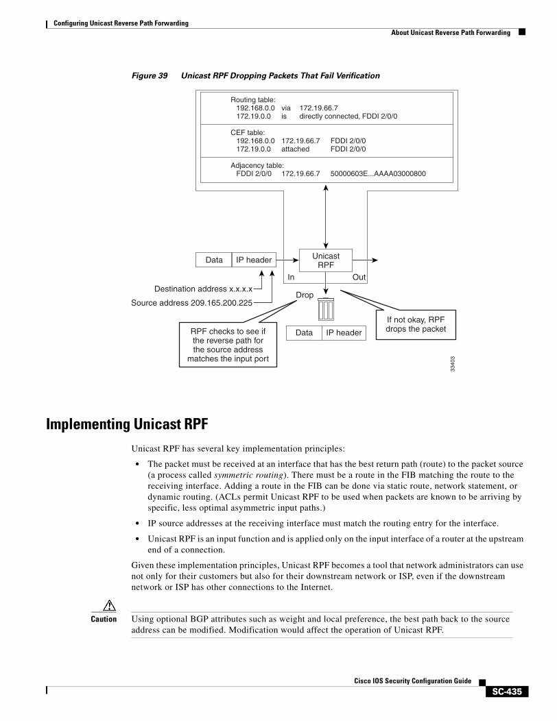
Configuring Unicast Reverse Path ForwardingAbout Unicast Reverse Path Forwarding
SC-435Cisco IOS Security Configuration Guide
Figure 39 Unicast RPF Dropping Packets That Fail Verification
Implementing Unicast RPF Unicast RPF has several key implementation principles:
• The packet must be received at an interface that has the best return path (route) to the packet source (a process called symmetric routing). There must be a route in the FIB matching the route to the receiving interface. Adding a route in the FIB can be done via static route, network statement, or dynamic routing. (ACLs permit Unicast RPF to be used when packets are known to be arriving by specific, less optimal asymmetric input paths.)
• IP source addresses at the receiving interface must match the routing entry for the interface.
• Unicast RPF is an input function and is applied only on the input interface of a router at the upstream end of a connection.
Given these implementation principles, Unicast RPF becomes a tool that network administrators can use not only for their customers but also for their downstream network or ISP, even if the downstream network or ISP has other connections to the Internet.
Caution Using optional BGP attributes such as weight and local preference, the best path back to the source address can be modified. Modification would affect the operation of Unicast RPF.
Destination address x.x.x.x
Source address 209.165.200.225
UnicastRPF
In
Drop
Out
Routing table:192.168.0.0 via 172.19.66.7172.19.0.0 is directly connected, FDDI 2/0/0
CEF table:192.168.0.0 172.19.66.7 FDDI 2/0/0172.19.0.0 attached FDDI 2/0/0
Adjacency table:FDDI 2/0/0 172.19.66.7 50000603E...AAAA03000800
RPF checks to see ifthe reverse path forthe source address
matches the input port
If not okay, RPFdrops the packet
3340
3
Data IP header
Data IP header
Configuring Unicast Reverse Path ForwardingAbout Unicast Reverse Path Forwarding
SC-436Cisco IOS Security Configuration Guide
This section provides information about the implementation of Unicast RPF:
• Security Policy and Unicast RPF
• Where to Use Unicast RPF
• Routing Table Requirements
• Where Not to Use Unicast RPF
• Unicast RPF with BOOTP and DHCP
Security Policy and Unicast RPF
Consider the following points in determining your policy for deploying Unicast RPF:
• Unicast RPF must be applied at the interface downstream from the larger portion of the network, preferably at the edges of your network.
• The further downstream you apply Unicast RPF, the finer the granularity you have in mitigating address spoofing and in identifying the sources of spoofed addresses. For example, applying Unicast RPF on an aggregation router helps mitigate attacks from many downstream networks or clients and is simple to administer, but it does not help identify the source of the attack. Applying Unicast RPF at the network access server helps limit the scope of the attack and trace the source of the attack; however, deploying Unicast RPF across many sites does add to the administration cost of operating the network.
• The more entities that deploy Unicast RPF across Internet, intranet, and extranet resources, the better the chances of mitigating large-scale network disruptions throughout the Internet community, and the better the chances of tracing the source of an attack.
• Unicast RPF will not inspect IP packets encapsulated in tunnels, such as GRE, LT2P, or PPTP. Unicast RPF must be configured at a home gateway so that Unicast RPF processes network traffic only after the tunneling and encryption layers have been stripped off the packets.
Where to Use Unicast RPF
Unicast RPF can be used in any “single-homed” environment where there is essentially only one access point out of the network; that is, one upstream connection. Networks having one access point offer the best example of symmetric routing, which means that the interface where a packet enters the network is also the best return path to the source of the IP packet. Unicast RPF is best used at the network perimeter for Internet, intranet, or extranet environments, or in ISP environments for customer network terminations.
The following sections provide a look at implementing Unicast RPF in two network environments:
• Enterprise Networks with a Single Connection to an ISP
• Network Access Server Application (Applying Unicast RPF in PSTN/ISDN PoP Aggregation Routers)
Enterprise Networks with a Single Connection to an ISP
In enterprise networks, one objective of using Unicast RPF for filtering traffic at the input interface (a process called ingress filtering) is for protection from malformed packets arriving from the Internet. Traditionally, local networks that have one connection to the Internet would use ACLs at the receiving interface to prevent spoofed packets from the Internet from entering their local network.
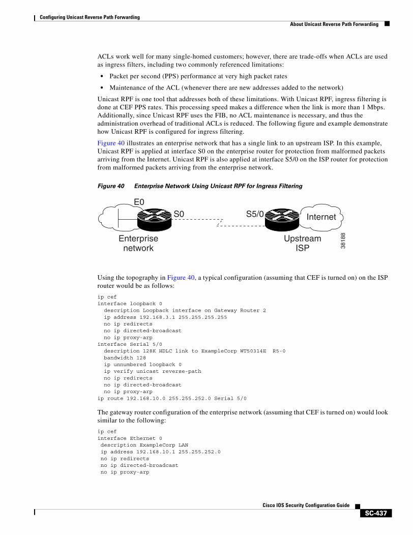
Configuring Unicast Reverse Path ForwardingAbout Unicast Reverse Path Forwarding
SC-437Cisco IOS Security Configuration Guide
ACLs work well for many single-homed customers; however, there are trade-offs when ACLs are used as ingress filters, including two commonly referenced limitations:
• Packet per second (PPS) performance at very high packet rates
• Maintenance of the ACL (whenever there are new addresses added to the network)
Unicast RPF is one tool that addresses both of these limitations. With Unicast RPF, ingress filtering is done at CEF PPS rates. This processing speed makes a difference when the link is more than 1 Mbps. Additionally, since Unicast RPF uses the FIB, no ACL maintenance is necessary, and thus the administration overhead of traditional ACLs is reduced. The following figure and example demonstrate how Unicast RPF is configured for ingress filtering.
Figure 40 illustrates an enterprise network that has a single link to an upstream ISP. In this example, Unicast RPF is applied at interface S0 on the enterprise router for protection from malformed packets arriving from the Internet. Unicast RPF is also applied at interface S5/0 on the ISP router for protection from malformed packets arriving from the enterprise network.
Figure 40 Enterprise Network Using Unicast RPF for Ingress Filtering
Using the topography in Figure 40, a typical configuration (assuming that CEF is turned on) on the ISP router would be as follows:
ip cefinterface loopback 0 description Loopback interface on Gateway Router 2 ip address 192.168.3.1 255.255.255.255
no ip redirects no ip directed-broadcast
no ip proxy-arpinterface Serial 5/0 description 128K HDLC link to ExampleCorp WT50314E R5-0 bandwidth 128 ip unnumbered loopback 0 ip verify unicast reverse-path no ip redirects no ip directed-broadcast no ip proxy-arpip route 192.168.10.0 255.255.252.0 Serial 5/0
The gateway router configuration of the enterprise network (assuming that CEF is turned on) would look similar to the following:
ip cefinterface Ethernet 0description ExampleCorp LANip address 192.168.10.1 255.255.252.0no ip redirectsno ip directed-broadcastno ip proxy-arp
InternetS5/0S0E0
UpstreamISP
Enterprisenetwork 38
188
Configuring Unicast Reverse Path ForwardingAbout Unicast Reverse Path Forwarding
SC-438Cisco IOS Security Configuration Guide
interface Serial 0description 128K HDLC link to ExampleCorp Internet Inc WT50314E C0bandwidth 128ip unnumbered ethernet 0ip verify unicast reverse-pathno ip redirectsno ip directed-broadcastno ip proxy-arp
ip route 0.0.0.0 0.0.0.0 Serial 0
Notice that Unicast RPF works with a single default route. There are no additional routes or routing protocols. Network 192.168.10.0/22 is a connected network. Hence, packets coming from the Internet with a source address in the range 192.168.10.0/22 will be dropped by Unicast RPF.
Network Access Server Application (Applying Unicast RPF in PSTN/ISDN PoP Aggregation Routers)
Aggregation routers are ideal places to use Unicast RPF with single-homed clients. Unicast RPF works equally well on leased-line or PSTN/ISDN/xDSL customer connections into the Internet. In fact, dialup connections are reputed to be the greatest source of DoS attacks using forged IP addresses. As long as the network access server supports CEF, Unicast RPF will work. In this topology, the customer aggregation routers need not have the full Internet routing table. Aggregation routers need the routing prefixes information (IP address block); hence, information configured or redistributed in the Interior Gateway Protocol (IGP) or Internal Border Gateway Protocol (IBGP) (depending on the way that you add customer routes into your network) would be enough for Unicast RPF to do its job.
Figure 41 illustrates the application of Unicast RPF to the aggregation and access routers for an Internet service provider (ISP) point of presence (POP), with the ISP routers providing dialup customer connections. In this example, Unicast RPF is applied upstream from the customer dialup connection router on the receiving (input) interfaces of the ISP aggregation routers.
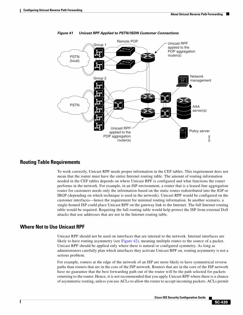
Configuring Unicast Reverse Path ForwardingAbout Unicast Reverse Path Forwarding
SC-439Cisco IOS Security Configuration Guide
Figure 41 Unicast RPF Applied to PSTN/ISDN Customer Connections
Routing Table Requirements
To work correctly, Unicast RPF needs proper information in the CEF tables. This requirement does not mean that the router must have the entire Internet routing table. The amount of routing information needed in the CEF tables depends on where Unicast RPF is configured and what functions the router performs in the network. For example, in an ISP environment, a router that is a leased-line aggregation router for customers needs only the information based on the static routes redistributed into the IGP or IBGP (depending on which technique is used in the network). Unicast RPF would be configured on the customer interfaces—hence the requirement for minimal routing information. In another scenario, a single-homed ISP could place Unicast RPF on the gateway link to the Internet. The full Internet routing table would be required. Requiring the full routing table would help protect the ISP from external DoS attacks that use addresses that are not in the Internet routing table.
Where Not to Use Unicast RPF
Unicast RPF should not be used on interfaces that are internal to the network. Internal interfaces are likely to have routing asymmetry (see Figure 42), meaning multiple routes to the source of a packet. Unicast RPF should be applied only where there is natural or configured symmetry. As long as administrators carefully plan which interfaces they activate Unicast RPF on, routing asymmetry is not a serious problem.
For example, routers at the edge of the network of an ISP are more likely to have symmetrical reverse paths than routers that are in the core of the ISP network. Routers that are in the core of the ISP network have no guarantee that the best forwarding path out of the router will be the path selected for packets returning to the router. Hence, it is not recommended that you apply Unicast RPF where there is a chance of asymmetric routing, unless you use ACLs to allow the router to accept incoming packets. ACLs permit
3818
9
Remote POPGroup 1
PSTN(local)
PSTN
Group 2
AAAserver(s)
Networkmanagement
Policy server
Unicast RPFapplied to thePOP aggregationrouter(s)
Unicast RPFapplied to the
POP aggregationrouter(s)
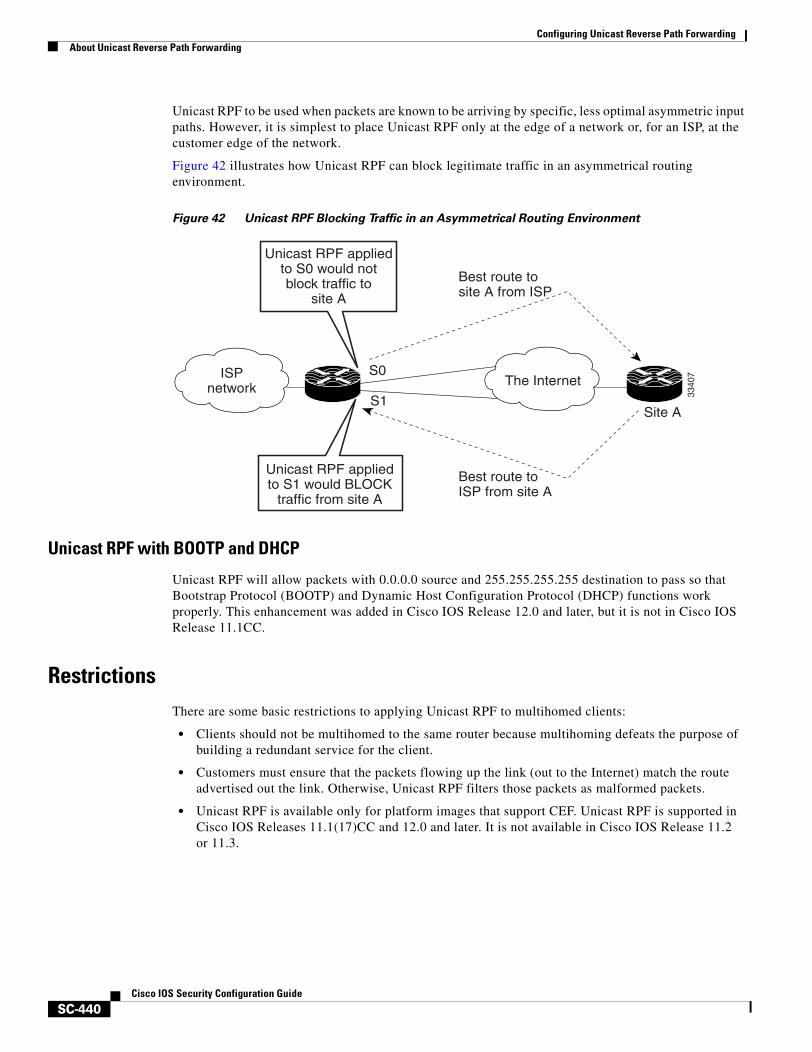
Configuring Unicast Reverse Path ForwardingAbout Unicast Reverse Path Forwarding
SC-440Cisco IOS Security Configuration Guide
Unicast RPF to be used when packets are known to be arriving by specific, less optimal asymmetric input paths. However, it is simplest to place Unicast RPF only at the edge of a network or, for an ISP, at the customer edge of the network.
Figure 42 illustrates how Unicast RPF can block legitimate traffic in an asymmetrical routing environment.
Figure 42 Unicast RPF Blocking Traffic in an Asymmetrical Routing Environment
Unicast RPF with BOOTP and DHCP
Unicast RPF will allow packets with 0.0.0.0 source and 255.255.255.255 destination to pass so that Bootstrap Protocol (BOOTP) and Dynamic Host Configuration Protocol (DHCP) functions work properly. This enhancement was added in Cisco IOS Release 12.0 and later, but it is not in Cisco IOS Release 11.1CC.
RestrictionsThere are some basic restrictions to applying Unicast RPF to multihomed clients:
• Clients should not be multihomed to the same router because multihoming defeats the purpose of building a redundant service for the client.
• Customers must ensure that the packets flowing up the link (out to the Internet) match the route advertised out the link. Otherwise, Unicast RPF filters those packets as malformed packets.
• Unicast RPF is available only for platform images that support CEF. Unicast RPF is supported in Cisco IOS Releases 11.1(17)CC and 12.0 and later. It is not available in Cisco IOS Release 11.2 or 11.3.
ISPnetwork The Internet
Site AS1
S0
Best route tosite A from ISP
Best route toISP from site A
3340
7
Unicast RPF appliedto S1 would BLOCK
traffic from site A
Unicast RPF appliedto S0 would notblock traffic to
site A
Configuring Unicast Reverse Path ForwardingAbout Unicast Reverse Path Forwarding
SC-441Cisco IOS Security Configuration Guide
Related Features and TechnologiesFor more information about Unicast RPF-related features and technologies, review the following:
• Unicast RPF requires Cisco express forwarding (CEF) to function properly on the router. For more information about CEF, refer to the Cisco IOS Switching Services Configuration Guide.
• Unicast RPF can be more effective at mitigating spoofing attacks when combined with a policy of ingress and egress filtering using Cisco IOS access control lists (ACLs).
– Ingress filtering applies filters to traffic received at a network interface from either internal or external networks. With ingress filtering, packets that arrive from other networks or the Internet and that have a source address that matches a local network, private, or broadcast address are dropped. In ISP environments, for example, ingress filtering can apply to traffic received at the router from either the client (customer) or the Internet.
– Egress filtering applies filters to traffic exiting a network interface (the sending interface). By filtering packets on routers that connect your network to the Internet or to other networks, you can permit only packets with valid source IP addresses to leave your network.
For more information on network filtering, refer to RFC 2267 and to the Cisco IOS IP Configuration Guide.
• Cisco IOS software provides additional features that can help mitigate DoS attacks:
– Committed Access Rate (CAR). CAR allows you to enforce a bandwidth policy against network traffic that matches an access list. For example, CAR allows you to rate-limit what should be low-volume traffic, such as ICMP traffic. To find out more about CAR, refer to the Cisco IOS Quality of Service Solutions Configuration Guide.
– Context-based Access Control (CBAC). CBAC selectively blocks any network traffic not originated by a protected network. CBAC uses timeout and threshold values to manage session state information, helping to determine when to drop sessions that do not become fully established. Setting timeout values for network sessions helps mitigate DoS attacks by freeing up system resources, dropping sessions after a specified amount of time. For more information on CBAC, refer to the Cisco IOS Security Configuration Guide.
– TCP Intercept. The TCP Intercept feature implements software to protect TCP servers from TCP SYN-flooding attacks, which are a type of DoS attack. A SYN-flooding attack occurs when a hacker floods a server with a barrage of requests for connection. Like CBAC, the TCP Intercept feature also uses timeout and threshold values to manage session state information, helping to determine when to drop sessions that do not become fully established. For more information on TCP Intercept, refer to the Cisco IOS Security Configuration Guide.
Configuring Unicast Reverse Path ForwardingUnicast RPF Configuration Task List
SC-442Cisco IOS Security Configuration Guide
Prerequisites to Configuring Unicast RPFPrior to configuring Unicast RPF, configure ACLs:
• Configure standard or extended ACLs to mitigate transmission of invalid IP addresses (perform egress filtering). Permit only valid source addresses to leave your network and get onto the Internet. Prevent all other source addresses from leaving your network for the Internet.
• Configure standard or extended ACLs entries to drop (deny) packets that have invalid source IP addresses (perform ingress filtering). Invalid source IP addresses include the following types:
– Reserved addresses
– Loopback addresses
– Private addresses (RFC 1918, Address Allocation for Private Internets)
– Broadcast addresses (including multicast addresses)
– Source addresses that fall outside the range of valid addresses associated with the protected network
• Configure standard or extended ACL entries to forward (permit) packets that fail the Unicast RPF checks to allow specific traffic from known asymmetric routed sources.
• Configure ACLs to track Unicast RPF events by adding the logging option into the ACL command. During network attacks, judicious logging of dropped or forwarded packets (suppressed drops) can provide additional information about network attacks.
Unicast RPF Configuration Task ListThe following sections describe the configuration tasks for Unicast RPF. Each task in the list is identified as either optional or required.
• Configuring Unicast RPF (Required)
• Verifying Unicast RPF (Optional)
See the section “Unicast RPF Configuration Examples” at the end of this chapter.
Configuring Unicast RPFTo use Unicast RPF, you must configure the router for CEF switching or CEF distributed switching. There is no need to configure the input interface for CEF switching because Unicast RPF has been implemented as a search through the FIB using the source IP address. As long as CEF is running on the router, individual interfaces can be configured with other switching modes. Unicast RPF is an input-side function that is enabled on an interface or subinterface that supports any type of encapsulation and operates on IP packets received by the router. It is very important that CEF be turned on globally in the router—Unicast RPF will not work without CEF.
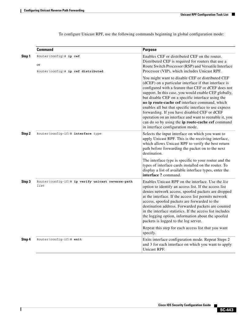
Configuring Unicast Reverse Path ForwardingUnicast RPF Configuration Task List
SC-443Cisco IOS Security Configuration Guide
To configure Unicast RPF, use the following commands beginning in global configuration mode:
Command Purpose
Step 1 Router(config)# ip cef
or
Router(config)# ip cef distributed
Enables CEF or distributed CEF on the router. Distributed CEF is required for routers that use a Route Switch Processor (RSP) and Versatile Interface Processor (VIP), which includes Unicast RPF.
You might want to disable CEF or distributed CEF (dCEF) on a particular interface if that interface is configured with a feature that CEF or dCEF does not support. In this case, you would enable CEF globally, but disable CEF on a specific interface using the no ip route-cache cef interface command, which enables all but that specific interface to use express forwarding. If you have disabled CEF or dCEF operation on an interface and want to reenable it, you can do so by using the ip route-cache cef command in interface configuration mode.
Step 2 Router(config-if)# interface type Selects the input interface on which you want to apply Unicast RPF. This is the receiving interface, which allows Unicast RPF to verify the best return path before forwarding the packet on to the next destination.
The interface type is specific to your router and the types of interface cards installed on the router. To display a list of available interface types, enter the interface ? command.
Step 3 Router(config-if)# ip verify unicast reverse-path list
Enables Unicast RPF on the interface. Use the list option to identify an access list. If the access list denies network access, spoofed packets are dropped at the interface. If the access list permits network access, spoofed packets are forwarded to the destination address. Forwarded packets are counted in the interface statistics. If the access list includes the logging option, information about the spoofed packets is logged to the log server.
Repeat this step for each access list that you want specify.
Step 4 Router(config-if)# exit Exits interface configuration mode. Repeat Steps 2 and 3 for each interface on which you want to apply Unicast RPF.
Configuring Unicast Reverse Path ForwardingTroubleshooting Tips
SC-444Cisco IOS Security Configuration Guide
Verifying Unicast RPFTo verify that Unicast RPF is operational, use the show cef interface command. The following example shows that Unicast RPF is enabled at interface serial2/0/0.
Router-3# show cef interface serial 2/0/0
Serial2/0/0 is up (if_number 8)Internet address is 192.168.10.2/30ICMP redirects are never sentPer packet loadbalancing is disabledIP unicast RPF check is enabledInbound access list is not setOutbound access list is not setInterface is marked as point to point interfacePackets switched to this interface on linecard are dropped to next slow pathHardware idb is Serial2/0/0Fast switching type 4, interface type 6IP Distributed CEF switching enabledIP LES Feature Fast switching turbo vectorIP Feature CEF switching turbo vectorInput fast flags 0x40, Output fast flags 0x0, ifindex 7(7)Slot 2 Slot unit 0 VC -1Transmit limit accumulator 0x48001A02 (0x48001A02)IP MTU 1500
Troubleshooting TipsIf you experience problems while using Unicast RPF, check the following items.
HSRP FailureFailure to disable Unicast RPF before disabling CEF can cause Hot Standby Router Protocol (HSRP) failure. If you want to disable CEF on the router, you must first disable Unicast RPF. To disable Unicast RPF, see the section “Monitoring and Maintaining Unicast RPF.”
Dropped Boot RequestsIn Cisco IOS Release 11.1(17)CC, Unicast RPF can drop BOOTP request packets that have a source address of 0.0.0.0 due to source address verification at the interface. To enable boot requests to work on the interface, you must use ACLs instead of Unicast RPF.
Configuring Unicast Reverse Path ForwardingMonitoring and Maintaining Unicast RPF
SC-445Cisco IOS Security Configuration Guide
Monitoring and Maintaining Unicast RPFThis section describes commands used to monitor and maintain Unicast RPF.
Caution To disable CEF, you must first disable Unicast RPF. Failure to disable Unicast RPF before disabling CEF can cause HSRP failure. If you want to disable CEF on the router, you must first disable Unicast RPF.
Unicast RPF counts the number of packets dropped or suppressed because of malformed or forged source addresses. Unicast RPF counts dropped or forwarded packets that include the following global and per-interface information:
• Global Unicast RPF drops
• Per-interface Unicast RPF drops
• Per-interface Unicast RPF suppressed drops
The show ip traffic command shows the total number (global count) of dropped or suppressed packets for all interfaces on the router. The Unicast RPF drop count is included in the IP statistics section.
Router# show ip trafficIP statistics: Rcvd: 1471590 total, 887368 local destination 0 format errors, 0 checksum errors, 301274 bad hop count 0 unknown protocol, 0 not a gateway 0 security failures, 0 bad options, 0 with options Opts: 0 end, 0 nop, 0 basic security, 0 loose source route 0 timestamp, 0 extended security, 0 record route 0 stream ID, 0 strict source route, 0 alert, 0 other Frags: 0 reassembled, 0 timeouts, 0 couldn't reassemble 0 fragmented, 0 couldn't fragment Bcast: 205233 received, 0 sent Mcast: 463292 received, 462118 sent Sent: 990158 generated, 282938 forwarded Drop: 3 encapsulation failed, 0 unresolved, 0 no adjacency 0 no route, 0 unicast RPF, 0 forced drop
A nonzero value for the count of dropped or suppressed packets can mean one of two things:
• Unicast RPF is dropping or suppressing packets that have a bad source address (normal operation).
• Unicast RPF is dropping or suppressing legitimate packets because the route is misconfigured to use Unicast RPF in environments where asymmetric routing exists; that is, where multiple paths can exist as the best return path for a source address.
Command Purpose
Router# show ip traffic Displays global router statistics about Unicast RPF drops and suppressed drops.
Router# show ip interface type Displays per-interface statistics about Unicast RPF drops and suppressed drops.
Router# show access-lists Displays the number of matches to a specific ACL.
Router(config-if)# no ip verify unicast reverse-path list Disables Unicast RPF at the interface. Use the list option to disable Unicast RPF for a specific ACL at the interface.
Configuring Unicast Reverse Path ForwardingUnicast RPF Configuration Examples
SC-446Cisco IOS Security Configuration Guide
The show ip interface command shows the total of dropped or suppressed packets at a specific interface. If Unicast RPF is configured to use a specific ACL, that ACL information is displayed along with the drop statistics.
Router> show ip interface ethernet0/1/1 Unicast RPF ACL 197 1 unicast RPF drop 1 unicast RPF suppressed drop
The show access-lists command displays the number of matches found for a specific entry in a specific access list.
Router> show access-listsExtended IP access list 197 deny ip 192.168.201.0 0.0.0.63 any log-input (1 match) permit ip 192.168.201.64 0.0.0.63 any log-input (1 match) deny ip 192.168.201.128 0.0.0.63 any log-input permit ip 192.168.201.192 0.0.0.63 any log-input
Unicast RPF Configuration ExamplesThis section provides the following configuration examples:
• Unicast RPF on a Leased-Line Aggregation Router Example
• Unicast RPF on the Cisco AS5800 Using Dialup Ports Example
• Unicast RPF with Inbound and Outbound Filters Example
• Unicast RPF with ACLs and Logging Example
Unicast RPF on a Leased-Line Aggregation Router ExampleThe following commands enable Unicast RPF on a serial interface:
ip cef! or “ip cef distributed” for RSP+VIP based routers!interface serial 5/0/0ip verify unicast reverse-path
Unicast RPF on the Cisco AS5800 Using Dialup Ports ExampleThe following example enables Unicast RPF on a Cisco AS5800. The interface Group-Async command makes it easy to apply Unicast RPF on all the dialup ports.
ip cef!interface Group-Async1ip verify unicast reverse-path
Unicast RPF with Inbound and Outbound Filters ExampleThe following example uses a very simple single-homed ISP to demonstrate the concepts of ingress and egress filters used in conjunction with Unicast RPF. The example illustrates an ISP-allocated classless interdomain routing (CIDR) block 209.165.202.128/28 that has both inbound and outbound filters on the
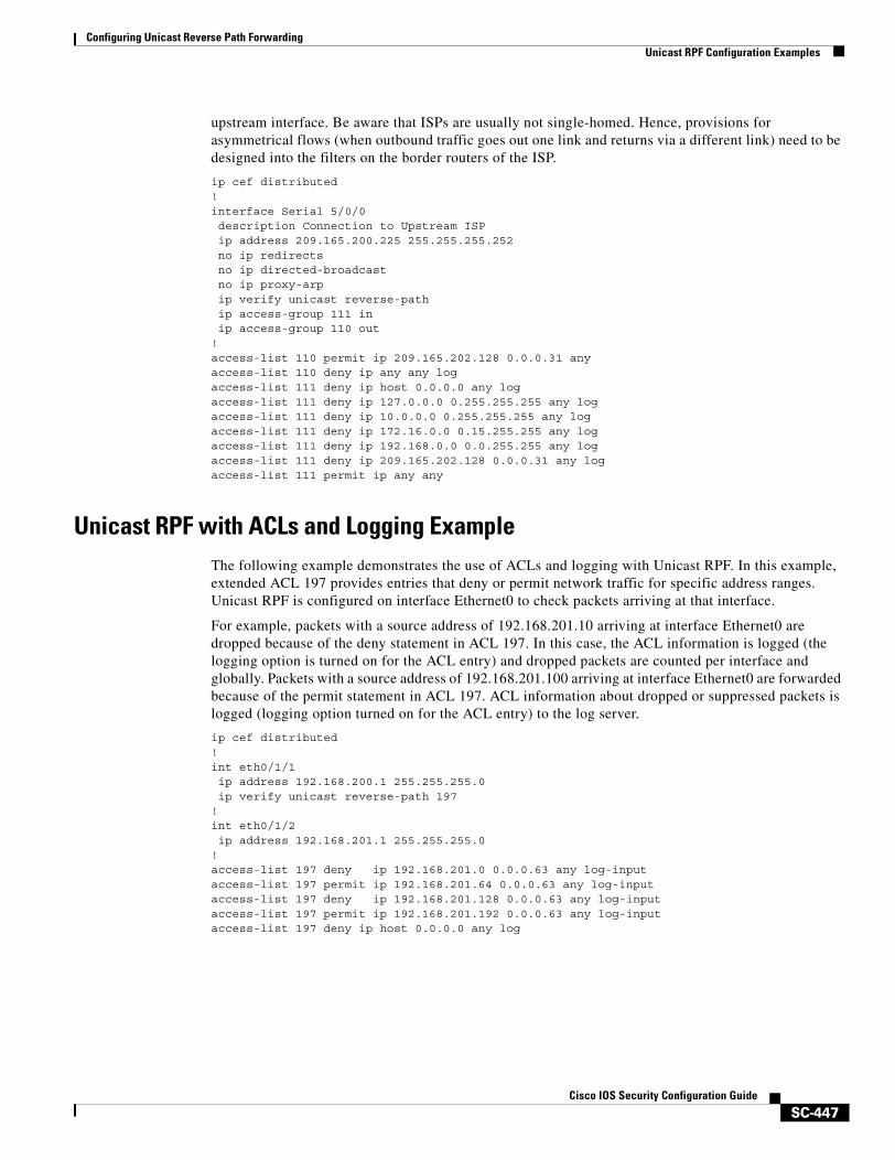
Configuring Unicast Reverse Path ForwardingUnicast RPF Configuration Examples
SC-447Cisco IOS Security Configuration Guide
upstream interface. Be aware that ISPs are usually not single-homed. Hence, provisions for asymmetrical flows (when outbound traffic goes out one link and returns via a different link) need to be designed into the filters on the border routers of the ISP.
ip cef distributed !interface Serial 5/0/0description Connection to Upstream ISPip address 209.165.200.225 255.255.255.252no ip redirectsno ip directed-broadcastno ip proxy-arpip verify unicast reverse-pathip access-group 111 inip access-group 110 out
!access-list 110 permit ip 209.165.202.128 0.0.0.31 anyaccess-list 110 deny ip any any log access-list 111 deny ip host 0.0.0.0 any logaccess-list 111 deny ip 127.0.0.0 0.255.255.255 any logaccess-list 111 deny ip 10.0.0.0 0.255.255.255 any logaccess-list 111 deny ip 172.16.0.0 0.15.255.255 any logaccess-list 111 deny ip 192.168.0.0 0.0.255.255 any logaccess-list 111 deny ip 209.165.202.128 0.0.0.31 any logaccess-list 111 permit ip any any
Unicast RPF with ACLs and Logging ExampleThe following example demonstrates the use of ACLs and logging with Unicast RPF. In this example, extended ACL 197 provides entries that deny or permit network traffic for specific address ranges. Unicast RPF is configured on interface Ethernet0 to check packets arriving at that interface.
For example, packets with a source address of 192.168.201.10 arriving at interface Ethernet0 are dropped because of the deny statement in ACL 197. In this case, the ACL information is logged (the logging option is turned on for the ACL entry) and dropped packets are counted per interface and globally. Packets with a source address of 192.168.201.100 arriving at interface Ethernet0 are forwarded because of the permit statement in ACL 197. ACL information about dropped or suppressed packets is logged (logging option turned on for the ACL entry) to the log server.
ip cef distributed!int eth0/1/1ip address 192.168.200.1 255.255.255.0ip verify unicast reverse-path 197
!int eth0/1/2ip address 192.168.201.1 255.255.255.0
!access-list 197 deny ip 192.168.201.0 0.0.0.63 any log-inputaccess-list 197 permit ip 192.168.201.64 0.0.0.63 any log-inputaccess-list 197 deny ip 192.168.201.128 0.0.0.63 any log-inputaccess-list 197 permit ip 192.168.201.192 0.0.0.63 any log-inputaccess-list 197 deny ip host 0.0.0.0 any log

Configuring Unicast Reverse Path ForwardingUnicast RPF Configuration Examples
SC-448Cisco IOS Security Configuration Guide

SC-449Cisco IOS Security Configuration Guide
Configuring Secure Shell
This chapter describes the Secure Shell (SSH) feature. The SSH feature consists of an application and a protocol.
For a complete description of the SSH commands in this chapter, refer to the chapter “Secure Shell Commands” of the Cisco IOS Security Command Reference. To locate documentation of other commands that appear in this chapter, use the command reference master index or search online.
To identify the hardware platform or software image information associated with a feature, use the Feature Navigator on Cisco.com to search for information about the feature or refer to the software release notes for a specific release. For more information, see the “Identifying Supported Platforms” section in the chapter “Using Cisco IOS Software.”
In This ChapterThis chapter has the following sections:
• About Secure Shell
• SSH Configuration Task List
• Troubleshooting Tips
• Monitoring and Maintaining SSH
• SSH Configuration Examples
About Secure ShellSecure Shell (SSH) is an application and a protocol that provide a secure replacement to the Berkeley r-tools. The protocol secures the sessions using standard cryptographic mechanisms, and the application can be used similarly to the Berkeley rexec and rsh tools. There are currently two versions of SSH available: SSH Version 1 and SSH Version 2. Only SSH Version 1 is implemented in the Cisco IOS software.
Note Hereafter, unless otherwise noted, the term “SSH” will denote “SSH Version 1” only.
Configuring Secure ShellAbout Secure Shell
SC-450Cisco IOS Security Configuration Guide
This rest of this section covers the following information:
• How SSH Works
• Restrictions
• Related Features and Technologies
• Prerequisites to Configuring SSH
How SSH WorksThis section provides the following information about how SSH works:
• SSH Server
• SSH Integrated Client
SSH Server
The SSH Server feature enables a SSH client to make a secure, encrypted connection to a Cisco router. This connection provides functionality that is similar to that of an inbound Telnet connection. Before SSH, security was limited to Telnet security. SSH allows a strong encryption to be used with the Cisco IOS software authentication. The SSH server in Cisco IOS software will work with publicly and commercially available SSH clients.
SSH Integrated Client
The SSH Integrated Client feature is an application running over the SSH protocol to provide device authentication and encryption. The SSH client enables a Cisco router to make a secure, encrypted connection to another Cisco router or to any other device running the SSH server. This connection provides functionality that is similar to that of an outbound Telnet connection except that the connection is encrypted. With authentication and encryption, the SSH client allows for a secure communication over an insecure network.
The SSH client in the Cisco IOS software works with publicly and commercially available SSH servers. The SSH client supports the ciphers of Data Encryption Standard (DES), Triple DES (3DES), and password authentication. User authentication is performed like that in the Telnet session to the router. The user authentication mechanisms supported for SSH are RADIUS, TACACS+ and the use of locally stored user names and passwords.
Note The SSH client functionality is available only when the SSH server is enabled.
RestrictionsThere following are some basic SSH restrictions:
• RSA authentication available in SSH clients is not supported in the SSH server for Cisco IOS software.
• SSH server and SSH client are supported on DES (56-bit) and 3DES (168-bit) data encryption software images only. In DES software images, DES is the only encryption algorithm available. In 3DES software images, both DES and 3DES encryption algorithms are available.
• Execution shell is the only application supported.
Configuring Secure ShellAbout Secure Shell
SC-451Cisco IOS Security Configuration Guide
Related Features and TechnologiesFor more information about SSH-related features and technologies, review the following:
• Authentication, Authorization, and Accounting (AAA) feature. AAA is a suite of network security services that provide the primary framework through which access control can be set up on your Cisco router or access server. For more information on AAA, refer to the Authentication, Authorization, and Accounting chapters earlier in this book and the Cisco IOS Security Command Reference.
• IP Security (IPSec) feature. IPSec is a framework of open standards that provides data confidentiality, data integrity, and data authentication between participating peers. IPSec provides these security services at the IP layer. IPSec uses Internet Key Exchange (IKE) to handle negotiation of protocols and algorithms based on local policy and to generate the encryption and authentication keys to be used by IPSec. IPSec can be used to protect one or more data flows between a pair of hosts, between a pair of security gateways, or between a security gateway and a host. For more information on IPSec, refer to the chapter “Configuring IPSec Network Security” and the Cisco IOS Security Command Reference.
Prerequisites to Configuring SSHPrior to configuring SSH, perform the following tasks:
• Download the required image on your router. (The SSH server requires you to have an IPSec (DES or 3DES) encryption software image from Cisco IOS Release 12.1(1)T downloaded on your router; the SSH client requires you to have an IPSec (DES or 3DES) encryption software image from Cisco IOS Release 12.1(3)T downloaded on your router.) For more information on downloading a software image, refer to the Cisco IOS Configuration Fundamentals Configuration Guide.
• Configure a host name and host domain for your router.
To configure a host name and host domain, enter the following commands beginning in global configuration mode:
• Generate an RSA key pair for your router, which automatically enables SSH.
Command PurposeRouter(config)# hostname hostname Configures a host name for your router.
Router(config)# ip domain-name domainname Configures a host domain for your router.
Configuring Secure ShellSSH Configuration Task List
SC-452Cisco IOS Security Configuration Guide
To generate an RSA key pair, enter the following global configuration command:
• Configure user authentication for local or remote access. You can configure authentication with or without AAA. For more information, refer to the “Authentication, Authorization, and Accounting (AAA)” chapters earlier in the book.
SSH Configuration Task ListThe following sections describe the configuration tasks for SSH. Each task in the list is identified as either optional or required.
• Configuring SSH Server (Required)
• Verifying SSH (Optional)
See the section “SSH Configuration Examples” at the end of this chapter.
Configuring SSH Server
Note The SSH client feature runs in user EXEC mode and has no specific configuration on the router.
Note The SSH commands are optional and are disabled when the SSH server is disabled.
To enable and configure a Cisco Router for SSH, you can configure SSH parameters. If you do not configure SSH parameters, the the default values will be used.
Command Purpose
Router(config)# crypto key generate rsa Enables the SSH server for local and remote authentication on the router.
The recommended minimum modulus size is 1024 bits.
Note To delete the RSA key-pair, use the crypto key zeroize rsa global configuration command. Once you delete the RSA key-pair, you automatically disable the SSH server.
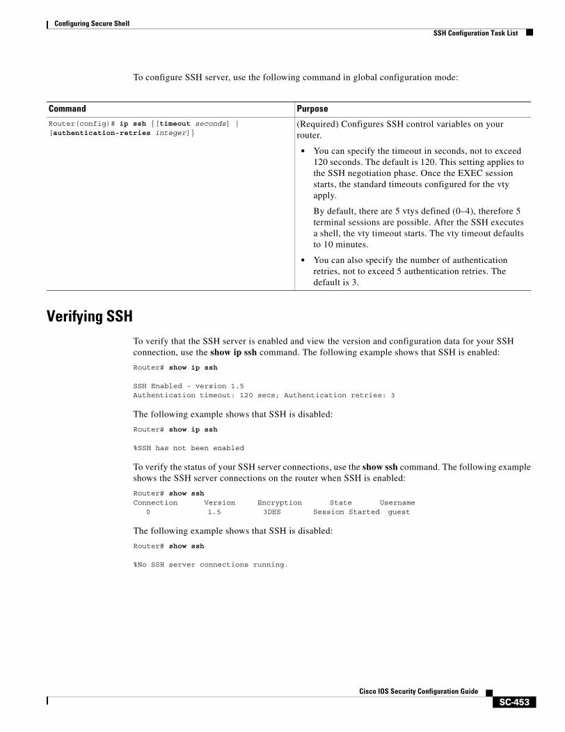
Configuring Secure ShellSSH Configuration Task List
SC-453Cisco IOS Security Configuration Guide
To configure SSH server, use the following command in global configuration mode:
Verifying SSHTo verify that the SSH server is enabled and view the version and configuration data for your SSH connection, use the show ip ssh command. The following example shows that SSH is enabled:
Router# show ip ssh
SSH Enabled - version 1.5Authentication timeout: 120 secs; Authentication retries: 3
The following example shows that SSH is disabled:
Router# show ip ssh
%SSH has not been enabled
To verify the status of your SSH server connections, use the show ssh command. The following example shows the SSH server connections on the router when SSH is enabled:
Router# show sshConnection Version Encryption State Username
0 1.5 3DES Session Started guest
The following example shows that SSH is disabled:
Router# show ssh
%No SSH server connections running.
Command PurposeRouter(config)# ip ssh {[timeout seconds] | [authentication-retries integer]}
(Required) Configures SSH control variables on your router.
• You can specify the timeout in seconds, not to exceed 120 seconds. The default is 120. This setting applies to the SSH negotiation phase. Once the EXEC session starts, the standard timeouts configured for the vty apply.
By default, there are 5 vtys defined (0–4), therefore 5 terminal sessions are possible. After the SSH executes a shell, the vty timeout starts. The vty timeout defaults to 10 minutes.
• You can also specify the number of authentication retries, not to exceed 5 authentication retries. The default is 3.
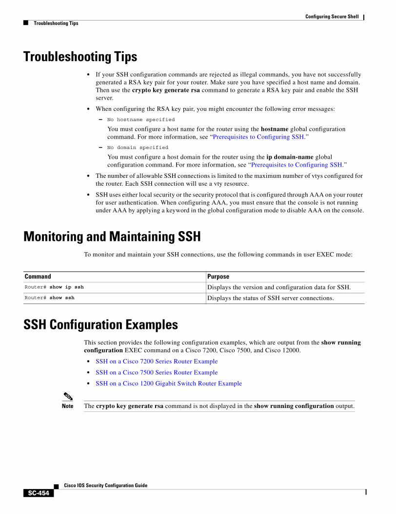
Configuring Secure ShellTroubleshooting Tips
SC-454Cisco IOS Security Configuration Guide
Troubleshooting Tips• If your SSH configuration commands are rejected as illegal commands, you have not successfully
generated a RSA key pair for your router. Make sure you have specified a host name and domain. Then use the crypto key generate rsa command to generate a RSA key pair and enable the SSH server.
• When configuring the RSA key pair, you might encounter the following error messages:
– No hostname specified
You must configure a host name for the router using the hostname global configuration command. For more information, see “Prerequisites to Configuring SSH.”
– No domain specified
You must configure a host domain for the router using the ip domain-name global configuration command. For more information, see “Prerequisites to Configuring SSH.”
• The number of allowable SSH connections is limited to the maximum number of vtys configured for the router. Each SSH connection will use a vty resource.
• SSH uses either local security or the security protocol that is configured through AAA on your router for user authentication. When configuring AAA, you must ensure that the console is not running under AAA by applying a keyword in the global configuration mode to disable AAA on the console.
Monitoring and Maintaining SSHTo monitor and maintain your SSH connections, use the following commands in user EXEC mode:
SSH Configuration ExamplesThis section provides the following configuration examples, which are output from the show running configuration EXEC command on a Cisco 7200, Cisco 7500, and Cisco 12000.
• SSH on a Cisco 7200 Series Router Example
• SSH on a Cisco 7500 Series Router Example
• SSH on a Cisco 1200 Gigabit Switch Router Example
Note The crypto key generate rsa command is not displayed in the show running configuration output.
Command PurposeRouter# show ip ssh Displays the version and configuration data for SSH.
Router# show ssh Displays the status of SSH server connections.
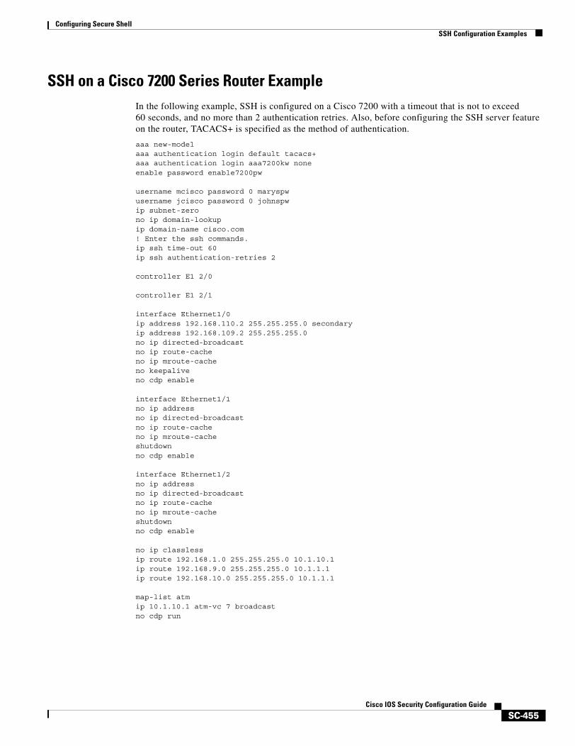
Configuring Secure ShellSSH Configuration Examples
SC-455Cisco IOS Security Configuration Guide
SSH on a Cisco 7200 Series Router ExampleIn the following example, SSH is configured on a Cisco 7200 with a timeout that is not to exceed 60 seconds, and no more than 2 authentication retries. Also, before configuring the SSH server feature on the router, TACACS+ is specified as the method of authentication.
aaa new-modelaaa authentication login default tacacs+aaa authentication login aaa7200kw noneenable password enable7200pw
username mcisco password 0 maryspwusername jcisco password 0 johnspwip subnet-zerono ip domain-lookupip domain-name cisco.com! Enter the ssh commands.ip ssh time-out 60ip ssh authentication-retries 2
controller E1 2/0
controller E1 2/1
interface Ethernet1/0ip address 192.168.110.2 255.255.255.0 secondaryip address 192.168.109.2 255.255.255.0no ip directed-broadcastno ip route-cacheno ip mroute-cacheno keepaliveno cdp enable
interface Ethernet1/1no ip addressno ip directed-broadcastno ip route-cacheno ip mroute-cacheshutdownno cdp enable
interface Ethernet1/2no ip addressno ip directed-broadcastno ip route-cacheno ip mroute-cacheshutdownno cdp enable
no ip classlessip route 192.168.1.0 255.255.255.0 10.1.10.1ip route 192.168.9.0 255.255.255.0 10.1.1.1ip route 192.168.10.0 255.255.255.0 10.1.1.1
map-list atmip 10.1.10.1 atm-vc 7 broadcastno cdp run
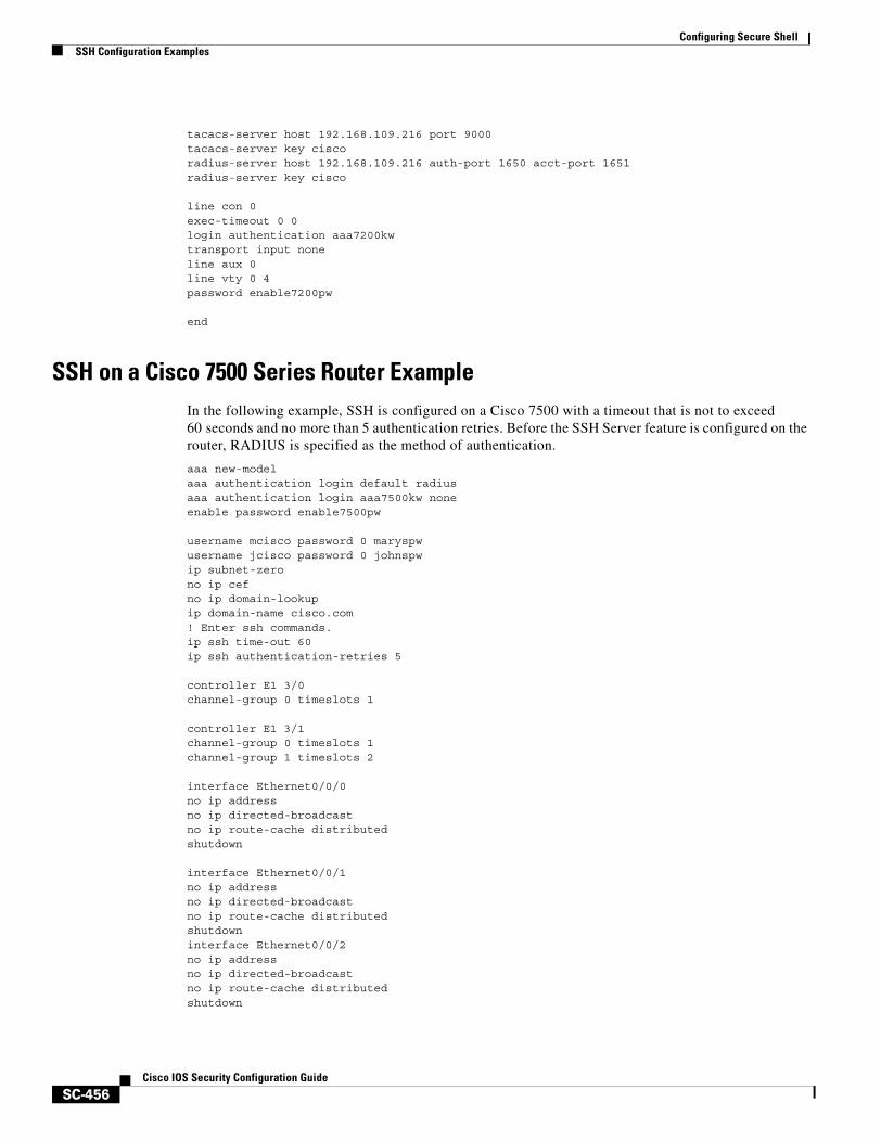
Configuring Secure ShellSSH Configuration Examples
SC-456Cisco IOS Security Configuration Guide
tacacs-server host 192.168.109.216 port 9000tacacs-server key ciscoradius-server host 192.168.109.216 auth-port 1650 acct-port 1651radius-server key cisco
line con 0exec-timeout 0 0login authentication aaa7200kwtransport input noneline aux 0line vty 0 4password enable7200pw
end
SSH on a Cisco 7500 Series Router ExampleIn the following example, SSH is configured on a Cisco 7500 with a timeout that is not to exceed 60 seconds and no more than 5 authentication retries. Before the SSH Server feature is configured on the router, RADIUS is specified as the method of authentication.
aaa new-modelaaa authentication login default radiusaaa authentication login aaa7500kw noneenable password enable7500pw username mcisco password 0 maryspwusername jcisco password 0 johnspwip subnet-zerono ip cefno ip domain-lookupip domain-name cisco.com! Enter ssh commands.ip ssh time-out 60ip ssh authentication-retries 5
controller E1 3/0channel-group 0 timeslots 1 controller E1 3/1channel-group 0 timeslots 1channel-group 1 timeslots 2
interface Ethernet0/0/0no ip addressno ip directed-broadcastno ip route-cache distributedshutdown interface Ethernet0/0/1no ip addressno ip directed-broadcastno ip route-cache distributedshutdowninterface Ethernet0/0/2no ip addressno ip directed-broadcastno ip route-cache distributedshutdown
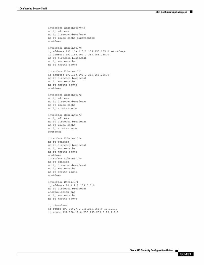
Configuring Secure ShellSSH Configuration Examples
SC-457Cisco IOS Security Configuration Guide
interface Ethernet0/0/3no ip addressno ip directed-broadcastno ip route-cache distributedshutdown interface Ethernet1/0ip address 192.168.110.2 255.255.255.0 secondaryip address 192.168.109.2 255.255.255.0no ip directed-broadcastno ip route-cacheno ip mroute-cache interface Ethernet1/1ip address 192.168.109.2 255.255.255.0no ip directed-broadcastno ip route-cacheno ip mroute-cacheshutdown interface Ethernet1/2no ip addressno ip directed-broadcastno ip route-cacheno ip mroute-cache interface Ethernet1/3no ip addressno ip directed-broadcastno ip route-cacheno ip mroute-cacheshutdown interface Ethernet1/4no ip addressno ip directed-broadcastno ip route-cacheno ip mroute-cacheshutdowninterface Ethernet1/5no ip addressno ip directed-broadcastno ip route-cacheno ip mroute-cacheshutdown interface Serial2/0ip address 10.1.1.2 255.0.0.0no ip directed-broadcastencapsulation pppno ip route-cacheno ip mroute-cache
ip classlessip route 192.168.9.0 255.255.255.0 10.1.1.1ip route 192.168.10.0 255.255.255.0 10.1.1.1
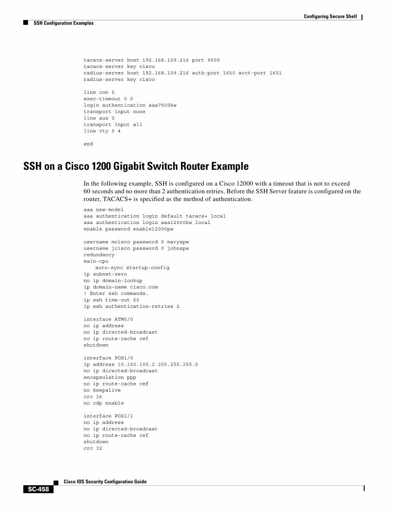
Configuring Secure ShellSSH Configuration Examples
SC-458Cisco IOS Security Configuration Guide
tacacs-server host 192.168.109.216 port 9000tacacs-server key ciscoradius-server host 192.168.109.216 auth-port 1650 acct-port 1651radius-server key cisco
line con 0exec-timeout 0 0login authentication aaa7500kwtransport input noneline aux 0transport input allline vty 0 4 end
SSH on a Cisco 1200 Gigabit Switch Router ExampleIn the following example, SSH is configured on a Cisco 12000 with a timeout that is not to exceed 60 seconds and no more than 2 authentication retries. Before the SSH Server feature is configured on the router, TACACS+ is specified as the method of authentication.
aaa new-modelaaa authentication login default tacacs+ localaaa authentication login aaa12000kw localenable password enable12000pw username mcisco password 0 maryspwusername jcisco password 0 johnspwredundancymain-cpu
auto-sync startup-configip subnet-zerono ip domain-lookupip domain-name cisco.com! Enter ssh commands.ip ssh time-out 60ip ssh authentication-retries 2
interface ATM0/0no ip addressno ip directed-broadcastno ip route-cache cefshutdown
interface POS1/0ip address 10.100.100.2 255.255.255.0no ip directed-broadcastencapsulation pppno ip route-cache cefno keepalivecrc 16no cdp enable interface POS1/1no ip addressno ip directed-broadcastno ip route-cache cefshutdowncrc 32
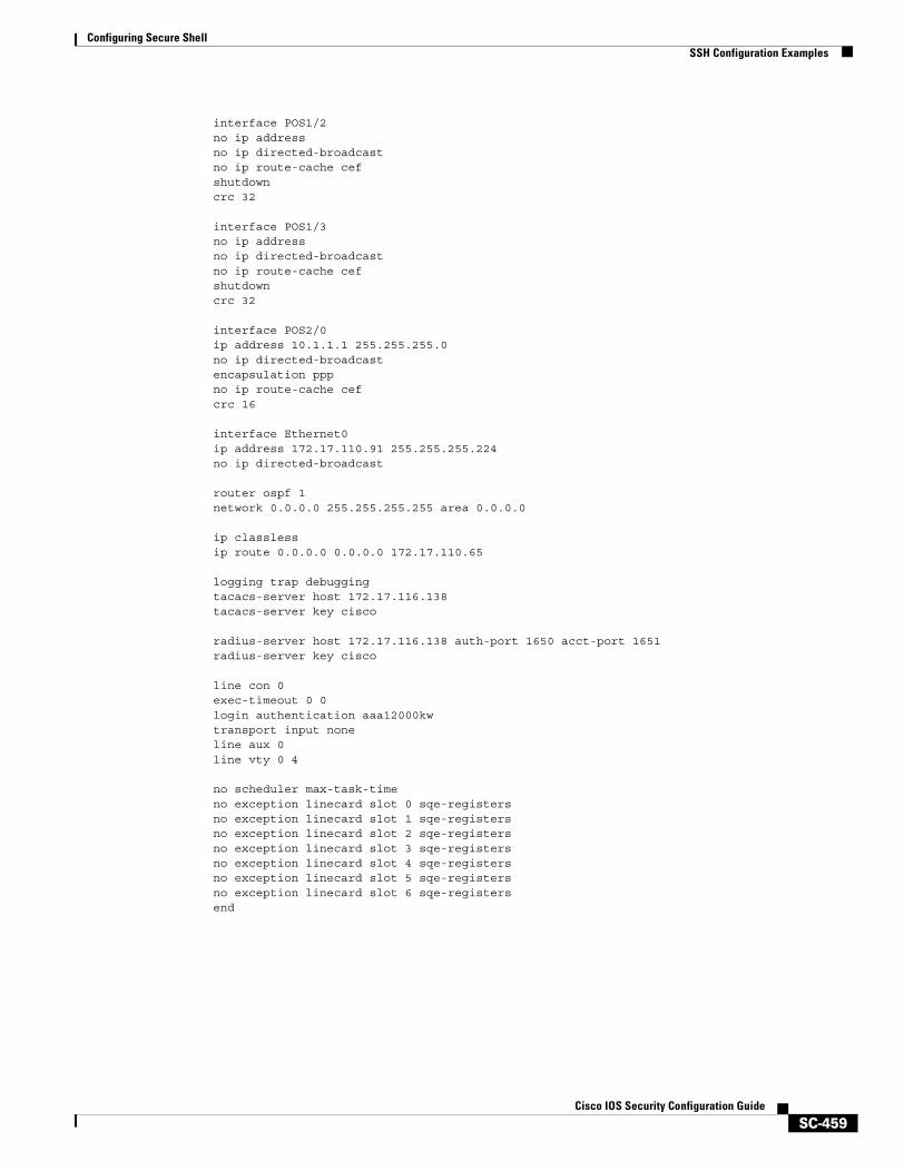
Configuring Secure ShellSSH Configuration Examples
SC-459Cisco IOS Security Configuration Guide
interface POS1/2no ip addressno ip directed-broadcastno ip route-cache cefshutdowncrc 32 interface POS1/3no ip addressno ip directed-broadcastno ip route-cache cefshutdowncrc 32 interface POS2/0ip address 10.1.1.1 255.255.255.0no ip directed-broadcastencapsulation pppno ip route-cache cefcrc 16 interface Ethernet0ip address 172.17.110.91 255.255.255.224no ip directed-broadcast router ospf 1network 0.0.0.0 255.255.255.255 area 0.0.0.0
ip classlessip route 0.0.0.0 0.0.0.0 172.17.110.65 logging trap debuggingtacacs-server host 172.17.116.138tacacs-server key cisco radius-server host 172.17.116.138 auth-port 1650 acct-port 1651radius-server key cisco line con 0exec-timeout 0 0login authentication aaa12000kwtransport input noneline aux 0line vty 0 4 no scheduler max-task-timeno exception linecard slot 0 sqe-registersno exception linecard slot 1 sqe-registersno exception linecard slot 2 sqe-registersno exception linecard slot 3 sqe-registersno exception linecard slot 4 sqe-registersno exception linecard slot 5 sqe-registersno exception linecard slot 6 sqe-registersend

Configuring Secure ShellSSH Configuration Examples
SC-460Cisco IOS Security Configuration Guide

Appendixes

SC-463Cisco IOS Security Configuration Guide
RADIUS Attributes Overview
Remote Authentication Dial-In User Service (RADIUS) attributes are used to define specific authentication, authorization, and accounting (AAA) elements in a user profile, which is stored on the RADIUS daemon. This appendix lists the RADIUS attributes currently supported.
In This AppendixThis appendix contains the following sections:
• RADIUS Attributes Overview
• RADIUS IETF Attributes
• Vendor-Proprietary RADIUS Attributes
• RADIUS Vendor-Specific Attributes (VSA)
• RADIUS Disconnect-Cause Attribute Values
RADIUS Attributes OverviewThis section contains information important to understanding how RADIUS attributes exchange AAA information between a client and server and includes the following sections:
• IETF Attributes Versus VSAs
• RADIUS Packet Format
• RADIUS Files
• Supporting Documentation
IETF Attributes Versus VSAsRADIUS Internet Engineering Task Force (IETF) attributes are the original set of 255 standard attributes that are used to communicate AAA information between a client and a server. Because IETF attributes are standard, the attribute data is predefined and well known; thus all clients and servers who exchange AAA information via IETF attributes must agree on attribute data such as the exact meaning of the attributes and the general bounds of the values for each attribute.
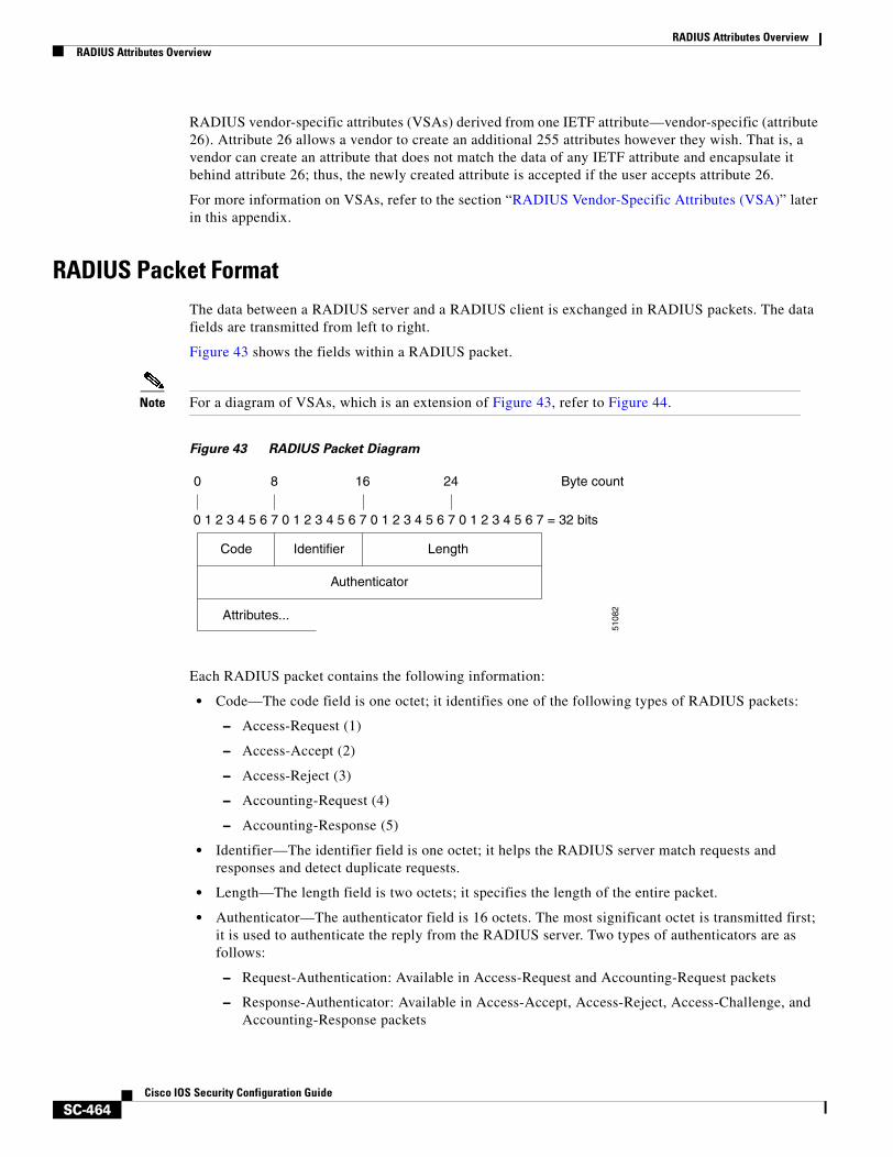
RADIUS Attributes OverviewRADIUS Attributes Overview
SC-464Cisco IOS Security Configuration Guide
RADIUS vendor-specific attributes (VSAs) derived from one IETF attribute—vendor-specific (attribute 26). Attribute 26 allows a vendor to create an additional 255 attributes however they wish. That is, a vendor can create an attribute that does not match the data of any IETF attribute and encapsulate it behind attribute 26; thus, the newly created attribute is accepted if the user accepts attribute 26.
For more information on VSAs, refer to the section “RADIUS Vendor-Specific Attributes (VSA)” later in this appendix.
RADIUS Packet FormatThe data between a RADIUS server and a RADIUS client is exchanged in RADIUS packets. The data fields are transmitted from left to right.
Figure 43 shows the fields within a RADIUS packet.
Note For a diagram of VSAs, which is an extension of Figure 43, refer to Figure 44.
Figure 43 RADIUS Packet Diagram
Each RADIUS packet contains the following information:
• Code—The code field is one octet; it identifies one of the following types of RADIUS packets:
– Access-Request (1)
– Access-Accept (2)
– Access-Reject (3)
– Accounting-Request (4)
– Accounting-Response (5)
• Identifier—The identifier field is one octet; it helps the RADIUS server match requests and responses and detect duplicate requests.
• Length—The length field is two octets; it specifies the length of the entire packet.
• Authenticator—The authenticator field is 16 octets. The most significant octet is transmitted first; it is used to authenticate the reply from the RADIUS server. Two types of authenticators are as follows:
– Request-Authentication: Available in Access-Request and Accounting-Request packets
– Response-Authenticator: Available in Access-Accept, Access-Reject, Access-Challenge, and Accounting-Response packets
0 1 2 3 4 5 6 7 0 1 2 3 4 5 6 7 0 1 2 3 4 5 6 7 0 1 2 3 4 5 6 7 = 32 bits
0 8
Code
Attributes...
Identifier Length
Authenticator
16 24 Byte count
5108
2
RADIUS Attributes OverviewRADIUS Attributes Overview
SC-465Cisco IOS Security Configuration Guide
RADIUS Packet Types
The following list defines the various types of RADIUS packet types that can contain attribute information:
Access-Request—Sent from a client to a RADIUS server. The packet contains information that allows the RADIUS server to determine whether to allow access to a specific network access server (NAS), which will allow access to the user. Any user performing authentication must submit an Access-Request packet. Once an Access-Request packet is received, the RADIUS server must forward a reply.
Access-Accept—Once a RADIUS server receives an Access-Request packet, it must send an Access-Accept packet if all attribute values in the Access-Request packet are acceptable. Access-Accept packets provide the configuration information necessary for the client to provide service to the user.
Access-Reject—Once a RADIUS server receives an Access-Request packet, it must send an Access-Reject packet if any of the attribute values are not acceptable.
Access-Challenge—Once the RADIUS server receives an Access-Accept packet, it can send the client an Access-Challenge packet, which requires a response. If the client does not know how to respond or if the packets are invalid, the RADIUS server discards the packets. If the client responds to the packet, a new Access-Request packet should be sent with the original Access-Request packet.
Accounting-Request—Sent from a client to a RADIUS accounting server, which provides accounting information. If the RADIUS server successfully records the Accounting-Request packet, it must submit an Accounting Response packet.
Accounting-Response—Sent by the RADIUS accounting server to the client to acknowledge that the Accounting-Request has been received and recorded successfully.
RADIUS FilesUnderstanding the types of files used by RADIUS is important for communicating AAA information from a client to a server. Each file defines a level of authentication or authorization for the user: The dictionary file defines which attributes the user’s NAS can implement; the clients file defines which users are allowed to make requests to the RADIUS server; the users files defines which user requests the RADIUS server will authenticate based on security and configuration data.
• Dictionary File
• Clients File
• Users File
Dictionary File
A dictionary file provides a list of attributes that are dependent upon which attributes your NAS supports. However, you can add your own set of attributes to your dictionary for custom solutions. It defines attribute values, thereby allowing you to interpret attribute output such as parsing requests. A dictionary file contains the following information:
• Name—The ASCII string “name” of the attribute, such as User-Name.
• ID—The numerical “name” of the attribute; for example, User-Name attribute is attribute 1.
• Value type—Each attribute can be specified as one of the following five value types:
– abinary—0 to 254 octets.
– date—32-bit value in big endian order. For example, seconds since 00:00:00 GMT, JAN. 1, 1970.
RADIUS Attributes OverviewRADIUS Attributes Overview
SC-466Cisco IOS Security Configuration Guide
– ipaddr—4 octets in network byte order.
– integer—32-bit value in big endian order (high byte first).
– string—0 to 253 octets.
When the data type for a particular attribute is an integer, you can optionally expand the integer to equate to some string. The follow sample dictionary includes an integer-based attribute and its corresponding values:
# dictionary sample of integer entry#ATTRIBUTE Service-Type 6 integer VALUE Service-Type Login 1VALUE Service-Type Framed 2VALUE Service-Type Callback-Login 3VALUE Service-Type Callback-Framed 4VALUE Service-Type Outbound 5VALUE Service-Type Administrative 6VALUE Service-Type NAS-Prompt 7VALUE Service-Type Authenticate-Only 8VALUE Service-Type Callback-NAS-Prompt 9VALUE Service-Type Call-Check 10VALUE Service-Type Callback-Administrative 11
Clients File
A clients file is important because it contains a list of RADIUS clients that are allowed to send authentication and accounting requests to the RADIUS server. To receive authentication, the name and authentication key the client sends the server must be an exact match with the data contained in clients file.
The following is an example of a clients file. The key, as shown in this example, must be the same as the radius-server key SomeSecret command.
#Client Name Key#---------------- ---------------10.1.2.3:256 testnas01 bananasnas02 MoNkEysnas07.foo.com SomeSecret
Users File
A RADIUS users file contains an entry for each user that the RADIUS server will authenticate; each entry, which is also referred to as a user profile, establishes an attribute the user can access.
The first line in any user profile is always a “user access” line; that is, the server must check the attributes on the first line before it can grant access to the user. The first line contains the name of the user, which can be up to 252 characters, followed by authentication information such as the password of the user.
Additional lines, which are associated with the user access line, indicate the attribute reply that is sent to the requesting client or server. The attributes sent in the reply must be defined in the dictionary file.
When looking at a user file, please note the the data to the left of the equal (=) character is an attribute defined in the dictionary file, and the data to the right of the equal character is the configuration data.
Note A blank line cannot appear anywhere within a user profile.
RADIUS Attributes OverviewRADIUS IETF Attributes
SC-467Cisco IOS Security Configuration Guide
The following is an example of a RADIUS user profile (Merit Daemon format). In this example, the user name is cisco.com, the password is cisco, and the user can access five tunnel attributes.
# This user profile includes RADIUS tunneling attributescisco.com Password="cisco" Service-Type=Outbound
Tunnel-Type = :1:L2TPTunnel-Medium-Type = :1:IPTunnel-Server-Endpoint = :1:10.0.0.1Tunnel-Password = :1:"welcome"Tunnel-Assignment-ID = :1:"nas"
Supporting DocumentationFor more information on RADIUS IETF and Vendor-Proprietary Attributes, refer to the following documents:
• Cisco AAA Implementation Case Study
• “Configuring RADIUS” “Configuring Authentication,” “Configuring Authorization,” and “Configuring Accounting” chapters in this book.
Refer to these chapters for information on how RADIUS is used with AAA.
• IETF RADIUS RFCs
– RFC 2865, Remote Authentication Dial In User Service (RADIUS)
– RFC 2866, RADIUS Accounting
– RFC 2867, RADIUS Accounting Modifications for Tunnel Protocol Support
– RFC 2868, RADIUS Attributes for Tunnel Protocol Support
– RFC 2869, RADIUS Extensions
• RADIUS Vendor-Specific Attributes Voice Implementation Guide
RADIUS IETF Attributes
Note In the Cisco IOS Release 12.2 for RADIUS tunnel attributes, 32 tagged tunnel sets are supported for L2TP.
This section contains the following sections:
• Supported RADIUS IETF Attributes
• Comprehensive List of RADIUS Attribute Descriptions
Supported RADIUS IETF AttributesTable 30 lists Cisco-supported IETF RADIUS attributes and the Cisco IOS release in which they are implemented. In cases where the attribute has a security server-specific format, the format is specified.
Refer to Table 31 for a description of each listed attribute.

RADIUS Attributes OverviewRADIUS IETF Attributes
SC-468Cisco IOS Security Configuration Guide
Note Attributes implemented in special (AA) or early development (T) releases will be added to the next mainline image.
Table 30 Supported RADIUS IETF Attributes
Number IETF Attribute 11.1 11.2 11.3 11.3 AA 11.3T 12.0 12.1 12.2
1 User-Name yes yes yes yes yes yes yes yes
2 User-Password yes yes yes yes yes yes yes yes
3 CHAP-Password yes yes yes yes yes yes yes yes
4 NAS-IP Address yes yes yes yes yes yes yes yes
5 NAS-Port yes yes yes yes yes yes yes yes
6 Service-Type yes yes yes yes yes yes yes yes
7 Framed-Protocol yes yes yes yes yes yes yes yes
8 Framed-IP-Address yes yes yes yes yes yes yes yes
9 Framed-IP-Netmask yes yes yes yes yes yes yes yes
10 Framed-Routing yes yes yes yes yes yes yes yes
11 Filter-Id yes yes yes yes yes yes yes yes
12 Framed-MTU yes yes yes yes yes yes yes yes
13 Framed-Compression yes yes yes yes yes yes yes yes
14 Login-IP-Host yes yes yes yes yes yes yes yes
15 Login-Service yes yes yes yes yes yes yes yes
16 Login-TCP-Port yes yes yes yes yes yes yes yes
18 Reply-Message yes yes yes yes yes yes yes yes
19 Callback-Number no no no no no no yes yes
20 Callback-ID no no no no no no no no
22 Framed-Route yes yes yes yes yes yes yes yes
23 Framed-IPX-Network no no no no no no no no
24 State yes yes yes yes yes yes yes yes
25 Class yes yes yes yes yes yes yes yes
26 Vendor-Specific yes yes yes yes yes yes yes yes
27 Session-Timeout yes yes yes yes yes yes yes yes
28 Idle-Timeout yes yes yes yes yes yes yes yes
29 Termination-Action no no no no no no no no
30 Called-Station-Id yes yes yes yes yes yes yes yes
31 Calling-Station-Id yes yes yes yes yes yes yes yes
32 NAS-Identifier no no no no no no no yes
33 Proxy-State no no no no no no no no
34 Login-LAT-Service yes yes yes yes yes yes yes yes
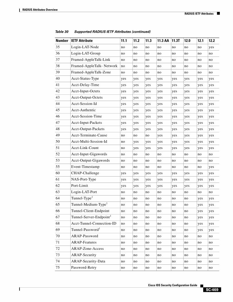
RADIUS Attributes OverviewRADIUS IETF Attributes
SC-469Cisco IOS Security Configuration Guide
35 Login-LAT-Node no no no no no no no yes
36 Login-LAT-Group no no no no no no no no
37 Framed-AppleTalk-Link no no no no no no no no
38 Framed-AppleTalk- Network no no no no no no no no
39 Framed-AppleTalk-Zone no no no no no no no no
40 Acct-Status-Type yes yes yes yes yes yes yes yes
41 Acct-Delay-Time yes yes yes yes yes yes yes yes
42 Acct-Input-Octets yes yes yes yes yes yes yes yes
43 Acct-Output-Octets yes yes yes yes yes yes yes yes
44 Acct-Session-Id yes yes yes yes yes yes yes yes
45 Acct-Authentic yes yes yes yes yes yes yes yes
46 Acct-Session-Time yes yes yes yes yes yes yes yes
47 Acct-Input-Packets yes yes yes yes yes yes yes yes
48 Acct-Output-Packets yes yes yes yes yes yes yes yes
49 Acct-Terminate-Cause no no no yes yes yes yes yes
50 Acct-Multi-Session-Id no yes yes yes yes yes yes yes
51 Acct-Link-Count no yes yes yes yes yes yes yes
52 Acct-Input-Gigawords no no no no no no no no
53 Acct-Output-Gigawords no no no no no no no no
55 Event-Timestamp no no no no no no no yes
60 CHAP-Challenge yes yes yes yes yes yes yes yes
61 NAS-Port-Type yes yes yes yes yes yes yes yes
62 Port-Limit yes yes yes yes yes yes yes yes
63 Login-LAT-Port no no no no no no no no
64 Tunnel-Type1 no no no no no no yes yes
65 Tunnel-Medium-Type1 no no no no no no yes yes
66 Tunnel-Client-Endpoint no no no no no no yes yes
67 Tunnel-Server-Endpoint1 no no no no no no yes yes
68 Acct-Tunnel-Connection-ID no no no no no no yes yes
69 Tunnel-Password1 no no no no no no yes yes
70 ARAP-Password no no no no no no no no
71 ARAP-Features no no no no no no no no
72 ARAP-Zone-Access no no no no no no no no
73 ARAP-Security no no no no no no no no
74 ARAP-Security-Data no no no no no no no no
75 Password-Retry no no no no no no no no
Table 30 Supported RADIUS IETF Attributes (continued)
Number IETF Attribute 11.1 11.2 11.3 11.3 AA 11.3T 12.0 12.1 12.2
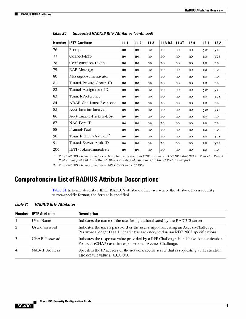
RADIUS Attributes OverviewRADIUS IETF Attributes
SC-470Cisco IOS Security Configuration Guide
Comprehensive List of RADIUS Attribute DescriptionsTable 31 lists and describes IETF RADIUS attributes. In cases where the attribute has a security server-specific format, the format is specified.
76 Prompt no no no no no no yes yes
77 Connect-Info no no no no no no no yes
78 Configuration-Token no no no no no no no no
79 EAP-Message no no no no no no no no
80 Message-Authenticator no no no no no no no no
81 Tunnel-Private-Group-ID no no no no no no no no
82 Tunnel-Assignment-ID1 no no no no no no yes yes
83 Tunnel-Preference no no no no no no no yes
84 ARAP-Challenge-Response no no no no no no no no
85 Acct-Interim-Interval no no no no no no yes yes
86 Acct-Tunnel-Packets-Lost no no no no no no no no
87 NAS-Port-ID no no no no no no no no
88 Framed-Pool no no no no no no no no
90 Tunnel-Client-Auth-ID2 no no no no no no no yes
91 Tunnel-Server-Auth-ID no no no no no no no yes
200 IETF-Token-Immediate no no no no no no no no
1. This RADIUS attribute complies with the following two draft IETF documents: RFC 2868 RADIUS Attributes for Tunnel Protocol Support and RFC 2867 RADIUS Accounting Modifications for Tunnel Protocol Support.
2. This RADIUS attribute complies withRFC 2865 and RFC 2868.
Table 30 Supported RADIUS IETF Attributes (continued)
Number IETF Attribute 11.1 11.2 11.3 11.3 AA 11.3T 12.0 12.1 12.2
Table 31 RADIUS IETF Attributes
Number IETF Attribute Description
1 User-Name Indicates the name of the user being authenticated by the RADIUS server.
2 User-Password Indicates the user’s password or the user’s input following an Access-Challenge. Passwords longer than 16 characters are encrypted using RFC 2865 specifications.
3 CHAP-Password Indicates the response value provided by a PPP Challenge-Handshake Authentication Protocol (CHAP) user in response to an Access-Challenge.
4 NAS-IP Address Specifies the IP address of the network access server that is requesting authentication. The default value is 0.0.0.0/0.
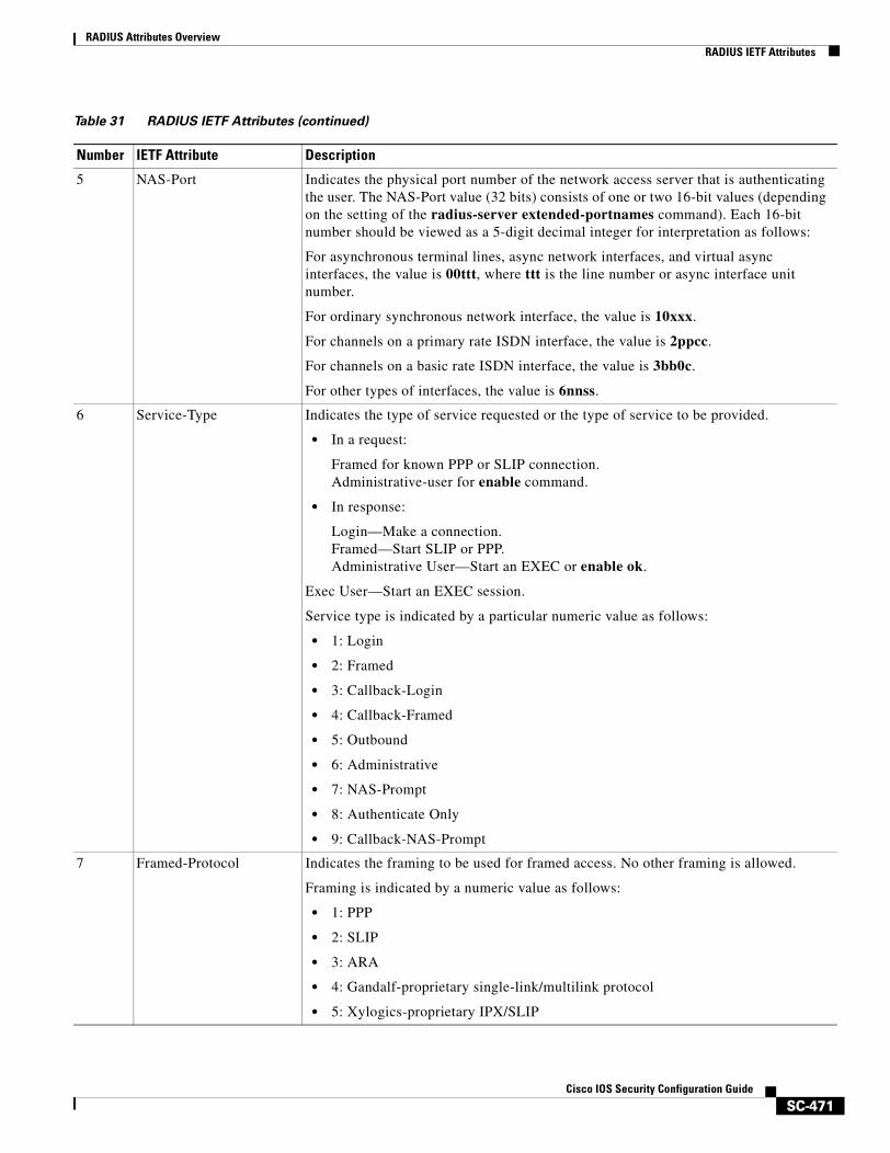
RADIUS Attributes OverviewRADIUS IETF Attributes
SC-471Cisco IOS Security Configuration Guide
5 NAS-Port Indicates the physical port number of the network access server that is authenticating the user. The NAS-Port value (32 bits) consists of one or two 16-bit values (depending on the setting of the radius-server extended-portnames command). Each 16-bit number should be viewed as a 5-digit decimal integer for interpretation as follows:
For asynchronous terminal lines, async network interfaces, and virtual async interfaces, the value is 00ttt, where ttt is the line number or async interface unit number.
For ordinary synchronous network interface, the value is 10xxx.
For channels on a primary rate ISDN interface, the value is 2ppcc.
For channels on a basic rate ISDN interface, the value is 3bb0c.
For other types of interfaces, the value is 6nnss.
6 Service-Type Indicates the type of service requested or the type of service to be provided.
• In a request:
Framed for known PPP or SLIP connection.Administrative-user for enable command.
• In response:
Login—Make a connection.Framed—Start SLIP or PPP.Administrative User—Start an EXEC or enable ok.
Exec User—Start an EXEC session.
Service type is indicated by a particular numeric value as follows:
• 1: Login
• 2: Framed
• 3: Callback-Login
• 4: Callback-Framed
• 5: Outbound
• 6: Administrative
• 7: NAS-Prompt
• 8: Authenticate Only
• 9: Callback-NAS-Prompt
7 Framed-Protocol Indicates the framing to be used for framed access. No other framing is allowed.
Framing is indicated by a numeric value as follows:
• 1: PPP
• 2: SLIP
• 3: ARA
• 4: Gandalf-proprietary single-link/multilink protocol
• 5: Xylogics-proprietary IPX/SLIP
Table 31 RADIUS IETF Attributes (continued)
Number IETF Attribute Description
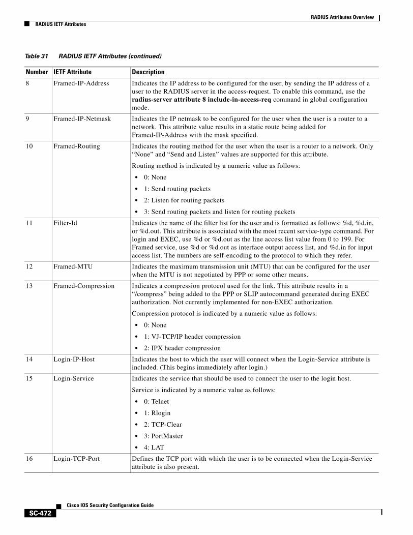
RADIUS Attributes OverviewRADIUS IETF Attributes
SC-472Cisco IOS Security Configuration Guide
8 Framed-IP-Address Indicates the IP address to be configured for the user, by sending the IP address of a user to the RADIUS server in the access-request. To enable this command, use the radius-server attribute 8 include-in-access-req command in global configuration mode.
9 Framed-IP-Netmask Indicates the IP netmask to be configured for the user when the user is a router to a network. This attribute value results in a static route being added for Framed-IP-Address with the mask specified.
10 Framed-Routing Indicates the routing method for the user when the user is a router to a network. Only “None” and “Send and Listen” values are supported for this attribute.
Routing method is indicated by a numeric value as follows:
• 0: None
• 1: Send routing packets
• 2: Listen for routing packets
• 3: Send routing packets and listen for routing packets
11 Filter-Id Indicates the name of the filter list for the user and is formatted as follows: %d, %d.in, or %d.out. This attribute is associated with the most recent service-type command. For login and EXEC, use %d or %d.out as the line access list value from 0 to 199. For Framed service, use %d or %d.out as interface output access list, and %d.in for input access list. The numbers are self-encoding to the protocol to which they refer.
12 Framed-MTU Indicates the maximum transmission unit (MTU) that can be configured for the user when the MTU is not negotiated by PPP or some other means.
13 Framed-Compression Indicates a compression protocol used for the link. This attribute results in a “/compress” being added to the PPP or SLIP autocommand generated during EXEC authorization. Not currently implemented for non-EXEC authorization.
Compression protocol is indicated by a numeric value as follows:
• 0: None
• 1: VJ-TCP/IP header compression
• 2: IPX header compression
14 Login-IP-Host Indicates the host to which the user will connect when the Login-Service attribute is included. (This begins immediately after login.)
15 Login-Service Indicates the service that should be used to connect the user to the login host.
Service is indicated by a numeric value as follows:
• 0: Telnet
• 1: Rlogin
• 2: TCP-Clear
• 3: PortMaster
• 4: LAT
16 Login-TCP-Port Defines the TCP port with which the user is to be connected when the Login-Service attribute is also present.
Table 31 RADIUS IETF Attributes (continued)
Number IETF Attribute Description
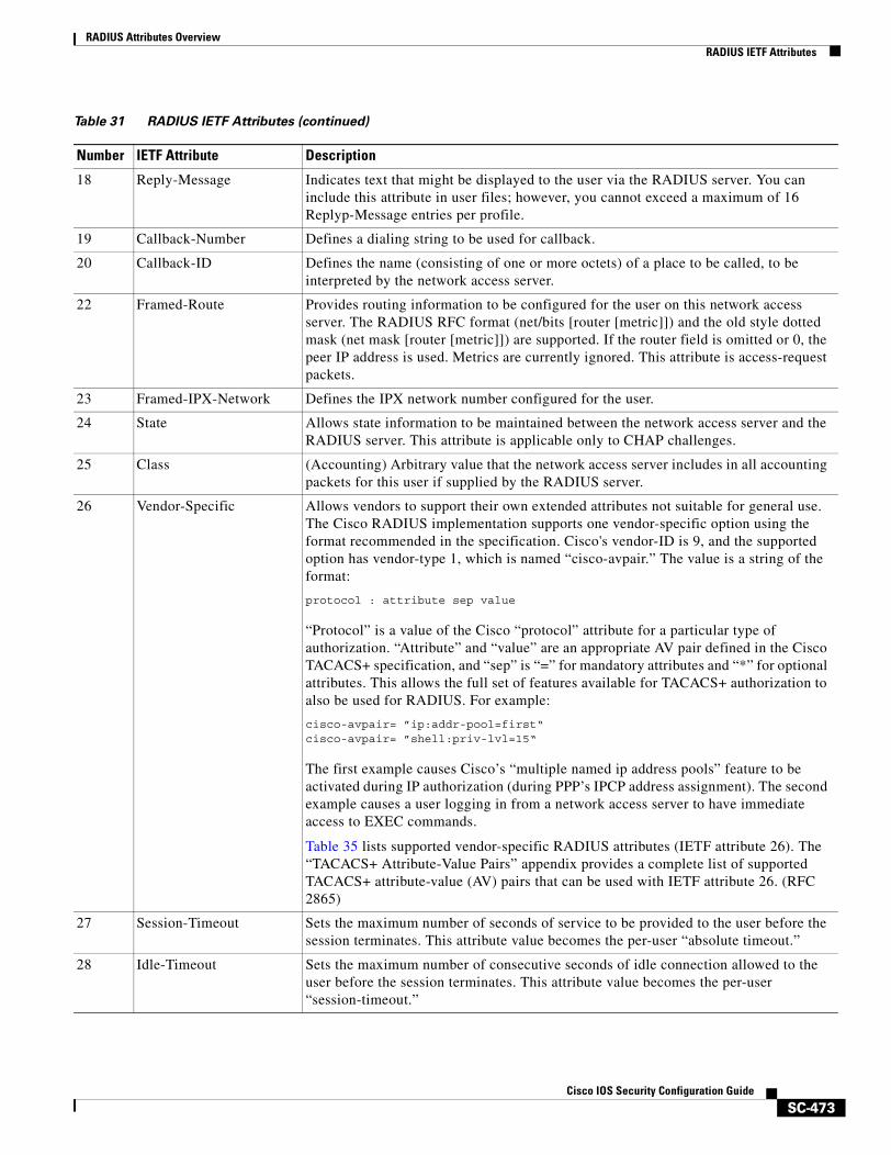
RADIUS Attributes OverviewRADIUS IETF Attributes
SC-473Cisco IOS Security Configuration Guide
18 Reply-Message Indicates text that might be displayed to the user via the RADIUS server. You can include this attribute in user files; however, you cannot exceed a maximum of 16 Replyp-Message entries per profile.
19 Callback-Number Defines a dialing string to be used for callback.
20 Callback-ID Defines the name (consisting of one or more octets) of a place to be called, to be interpreted by the network access server.
22 Framed-Route Provides routing information to be configured for the user on this network access server. The RADIUS RFC format (net/bits [router [metric]]) and the old style dotted mask (net mask [router [metric]]) are supported. If the router field is omitted or 0, the peer IP address is used. Metrics are currently ignored. This attribute is access-request packets.
23 Framed-IPX-Network Defines the IPX network number configured for the user.
24 State Allows state information to be maintained between the network access server and the RADIUS server. This attribute is applicable only to CHAP challenges.
25 Class (Accounting) Arbitrary value that the network access server includes in all accounting packets for this user if supplied by the RADIUS server.
26 Vendor-Specific Allows vendors to support their own extended attributes not suitable for general use. The Cisco RADIUS implementation supports one vendor-specific option using the format recommended in the specification. Cisco's vendor-ID is 9, and the supported option has vendor-type 1, which is named “cisco-avpair.” The value is a string of the format:
protocol : attribute sep value
“Protocol” is a value of the Cisco “protocol” attribute for a particular type of authorization. “Attribute” and “value” are an appropriate AV pair defined in the Cisco TACACS+ specification, and “sep” is “=” for mandatory attributes and “*” for optional attributes. This allows the full set of features available for TACACS+ authorization to also be used for RADIUS. For example:
cisco-avpair= ”ip:addr-pool=first“cisco-avpair= ”shell:priv-lvl=15“
The first example causes Cisco’s “multiple named ip address pools” feature to be activated during IP authorization (during PPP’s IPCP address assignment). The second example causes a user logging in from a network access server to have immediate access to EXEC commands.
Table 35 lists supported vendor-specific RADIUS attributes (IETF attribute 26). The “TACACS+ Attribute-Value Pairs” appendix provides a complete list of supported TACACS+ attribute-value (AV) pairs that can be used with IETF attribute 26. (RFC 2865)
27 Session-Timeout Sets the maximum number of seconds of service to be provided to the user before the session terminates. This attribute value becomes the per-user “absolute timeout.”
28 Idle-Timeout Sets the maximum number of consecutive seconds of idle connection allowed to the user before the session terminates. This attribute value becomes the per-user “session-timeout.”
Table 31 RADIUS IETF Attributes (continued)
Number IETF Attribute Description
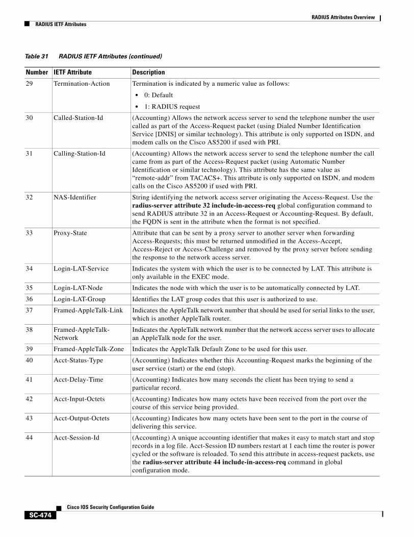
RADIUS Attributes OverviewRADIUS IETF Attributes
SC-474Cisco IOS Security Configuration Guide
29 Termination-Action Termination is indicated by a numeric value as follows:
• 0: Default
• 1: RADIUS request
30 Called-Station-Id (Accounting) Allows the network access server to send the telephone number the user called as part of the Access-Request packet (using Dialed Number Identification Service [DNIS] or similar technology). This attribute is only supported on ISDN, and modem calls on the Cisco AS5200 if used with PRI.
31 Calling-Station-Id (Accounting) Allows the network access server to send the telephone number the call came from as part of the Access-Request packet (using Automatic Number Identification or similar technology). This attribute has the same value as “remote-addr” from TACACS+. This attribute is only supported on ISDN, and modem calls on the Cisco AS5200 if used with PRI.
32 NAS-Identifier String identifying the network access server originating the Access-Request. Use the radius-server attribute 32 include-in-access-req global configuration command to send RADIUS attribute 32 in an Access-Request or Accounting-Request. By default, the FQDN is sent in the attribute when the format is not specified.
33 Proxy-State Attribute that can be sent by a proxy server to another server when forwarding Access-Requests; this must be returned unmodified in the Access-Accept, Access-Reject or Access-Challenge and removed by the proxy server before sending the response to the network access server.
34 Login-LAT-Service Indicates the system with which the user is to be connected by LAT. This attribute is only available in the EXEC mode.
35 Login-LAT-Node Indicates the node with which the user is to be automatically connected by LAT.
36 Login-LAT-Group Identifies the LAT group codes that this user is authorized to use.
37 Framed-AppleTalk-Link Indicates the AppleTalk network number that should be used for serial links to the user, which is another AppleTalk router.
38 Framed-AppleTalk-Network
Indicates the AppleTalk network number that the network access server uses to allocate an AppleTalk node for the user.
39 Framed-AppleTalk-Zone Indicates the AppleTalk Default Zone to be used for this user.
40 Acct-Status-Type (Accounting) Indicates whether this Accounting-Request marks the beginning of the user service (start) or the end (stop).
41 Acct-Delay-Time (Accounting) Indicates how many seconds the client has been trying to send a particular record.
42 Acct-Input-Octets (Accounting) Indicates how many octets have been received from the port over the course of this service being provided.
43 Acct-Output-Octets (Accounting) Indicates how many octets have been sent to the port in the course of delivering this service.
44 Acct-Session-Id (Accounting) A unique accounting identifier that makes it easy to match start and stop records in a log file. Acct-Session ID numbers restart at 1 each time the router is power cycled or the software is reloaded. To send this attribute in access-request packets, use the radius-server attribute 44 include-in-access-req command in global configuration mode.
Table 31 RADIUS IETF Attributes (continued)
Number IETF Attribute Description
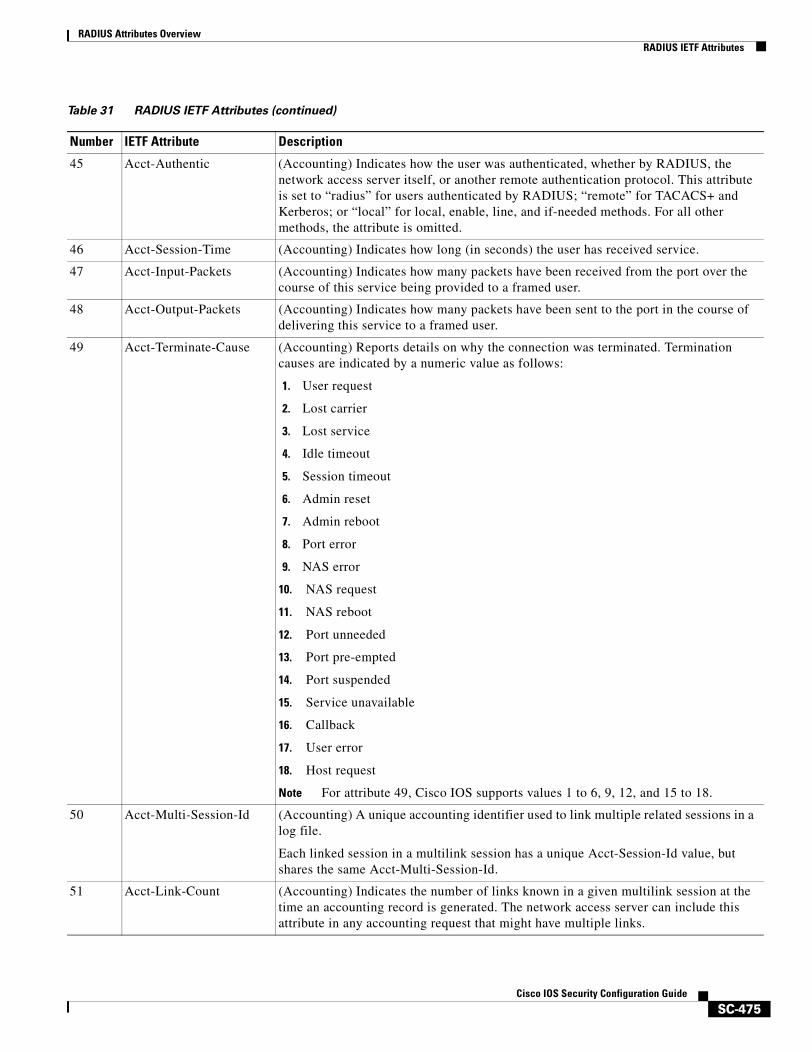
RADIUS Attributes OverviewRADIUS IETF Attributes
SC-475Cisco IOS Security Configuration Guide
45 Acct-Authentic (Accounting) Indicates how the user was authenticated, whether by RADIUS, the network access server itself, or another remote authentication protocol. This attribute is set to “radius” for users authenticated by RADIUS; “remote” for TACACS+ and Kerberos; or “local” for local, enable, line, and if-needed methods. For all other methods, the attribute is omitted.
46 Acct-Session-Time (Accounting) Indicates how long (in seconds) the user has received service.
47 Acct-Input-Packets (Accounting) Indicates how many packets have been received from the port over the course of this service being provided to a framed user.
48 Acct-Output-Packets (Accounting) Indicates how many packets have been sent to the port in the course of delivering this service to a framed user.
49 Acct-Terminate-Cause (Accounting) Reports details on why the connection was terminated. Termination causes are indicated by a numeric value as follows:
1. User request
2. Lost carrier
3. Lost service
4. Idle timeout
5. Session timeout
6. Admin reset
7. Admin reboot
8. Port error
9. NAS error
10. NAS request
11. NAS reboot
12. Port unneeded
13. Port pre-empted
14. Port suspended
15. Service unavailable
16. Callback
17. User error
18. Host request
Note For attribute 49, Cisco IOS supports values 1 to 6, 9, 12, and 15 to 18.
50 Acct-Multi-Session-Id (Accounting) A unique accounting identifier used to link multiple related sessions in a log file.
Each linked session in a multilink session has a unique Acct-Session-Id value, but shares the same Acct-Multi-Session-Id.
51 Acct-Link-Count (Accounting) Indicates the number of links known in a given multilink session at the time an accounting record is generated. The network access server can include this attribute in any accounting request that might have multiple links.
Table 31 RADIUS IETF Attributes (continued)
Number IETF Attribute Description
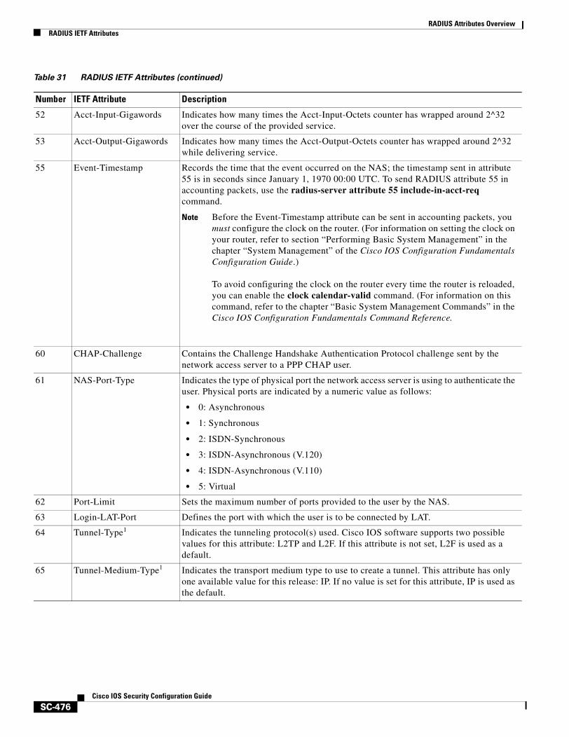
RADIUS Attributes OverviewRADIUS IETF Attributes
SC-476Cisco IOS Security Configuration Guide
52 Acct-Input-Gigawords Indicates how many times the Acct-Input-Octets counter has wrapped around 2^32 over the course of the provided service.
53 Acct-Output-Gigawords Indicates how many times the Acct-Output-Octets counter has wrapped around 2^32 while delivering service.
55 Event-Timestamp Records the time that the event occurred on the NAS; the timestamp sent in attribute 55 is in seconds since January 1, 1970 00:00 UTC. To send RADIUS attribute 55 in accounting packets, use the radius-server attribute 55 include-in-acct-req command.
Note Before the Event-Timestamp attribute can be sent in accounting packets, you must configure the clock on the router. (For information on setting the clock on your router, refer to section “Performing Basic System Management” in the chapter “System Management” of the Cisco IOS Configuration Fundamentals Configuration Guide.)
To avoid configuring the clock on the router every time the router is reloaded, you can enable the clock calendar-valid command. (For information on this command, refer to the chapter “Basic System Management Commands” in the Cisco IOS Configuration Fundamentals Command Reference.
60 CHAP-Challenge Contains the Challenge Handshake Authentication Protocol challenge sent by the network access server to a PPP CHAP user.
61 NAS-Port-Type Indicates the type of physical port the network access server is using to authenticate the user. Physical ports are indicated by a numeric value as follows:
• 0: Asynchronous
• 1: Synchronous
• 2: ISDN-Synchronous
• 3: ISDN-Asynchronous (V.120)
• 4: ISDN-Asynchronous (V.110)
• 5: Virtual
62 Port-Limit Sets the maximum number of ports provided to the user by the NAS.
63 Login-LAT-Port Defines the port with which the user is to be connected by LAT.
64 Tunnel-Type1 Indicates the tunneling protocol(s) used. Cisco IOS software supports two possible values for this attribute: L2TP and L2F. If this attribute is not set, L2F is used as a default.
65 Tunnel-Medium-Type1 Indicates the transport medium type to use to create a tunnel. This attribute has only one available value for this release: IP. If no value is set for this attribute, IP is used as the default.
Table 31 RADIUS IETF Attributes (continued)
Number IETF Attribute Description
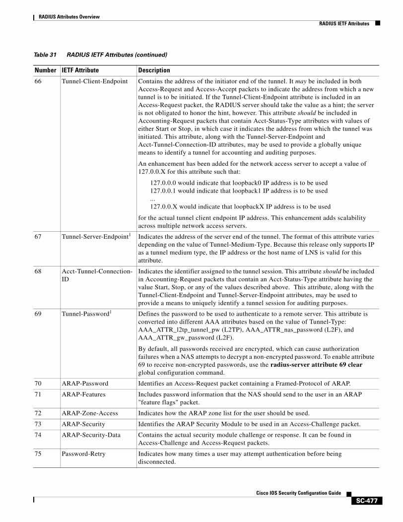
RADIUS Attributes OverviewRADIUS IETF Attributes
SC-477Cisco IOS Security Configuration Guide
66 Tunnel-Client-Endpoint Contains the address of the initiator end of the tunnel. It may be included in both Access-Request and Access-Accept packets to indicate the address from which a new tunnel is to be initiated. If the Tunnel-Client-Endpoint attribute is included in an Access-Request packet, the RADIUS server should take the value as a hint; the server is not obligated to honor the hint, however. This attribute should be included in Accounting-Request packets that contain Acct-Status-Type attributes with values of either Start or Stop, in which case it indicates the address from which the tunnel was initiated. This attribute, along with the Tunnel-Server-Endpoint and Acct-Tunnel-Connection-ID attributes, may be used to provide a globally unique means to identify a tunnel for accounting and auditing purposes.
An enhancement has been added for the network access server to accept a value of 127.0.0.X for this attribute such that:
127.0.0.0 would indicate that loopback0 IP address is to be used127.0.0.1 would indicate that loopback1 IP address is to be used...127.0.0.X would indicate that loopbackX IP address is to be used
for the actual tunnel client endpoint IP address. This enhancement adds scalability across multiple network access servers.
67 Tunnel-Server-Endpoint1 Indicates the address of the server end of the tunnel. The format of this attribute varies depending on the value of Tunnel-Medium-Type. Because this release only supports IP as a tunnel medium type, the IP address or the host name of LNS is valid for this attribute.
68 Acct-Tunnel-Connection-ID
Indicates the identifier assigned to the tunnel session. This attribute should be included in Accounting-Request packets that contain an Acct-Status-Type attribute having the value Start, Stop, or any of the values described above. This attribute, along with the Tunnel-Client-Endpoint and Tunnel-Server-Endpoint attributes, may be used to provide a means to uniquely identify a tunnel session for auditing purposes.
69 Tunnel-Password1 Defines the password to be used to authenticate to a remote server. This attribute is converted into different AAA attributes based on the value of Tunnel-Type: AAA_ATTR_l2tp_tunnel_pw (L2TP), AAA_ATTR_nas_password (L2F), and AAA_ATTR_gw_password (L2F).
By default, all passwords received are encrypted, which can cause authorization failures when a NAS attempts to decrypt a non-encrypted password. To enable attribute 69 to receive non-encrypted passwords, use the radius-server attribute 69 clear global configuration command.
70 ARAP-Password Identifies an Access-Request packet containing a Framed-Protocol of ARAP.
71 ARAP-Features Includes password information that the NAS should send to the user in an ARAP "feature flags" packet.
72 ARAP-Zone-Access Indicates how the ARAP zone list for the user should be used.
73 ARAP-Security Identifies the ARAP Security Module to be used in an Access-Challenge packet.
74 ARAP-Security-Data Contains the actual security module challenge or response. It can be found in Access-Challenge and Access-Request packets.
75 Password-Retry Indicates how many times a user may attempt authentication before being disconnected.
Table 31 RADIUS IETF Attributes (continued)
Number IETF Attribute Description
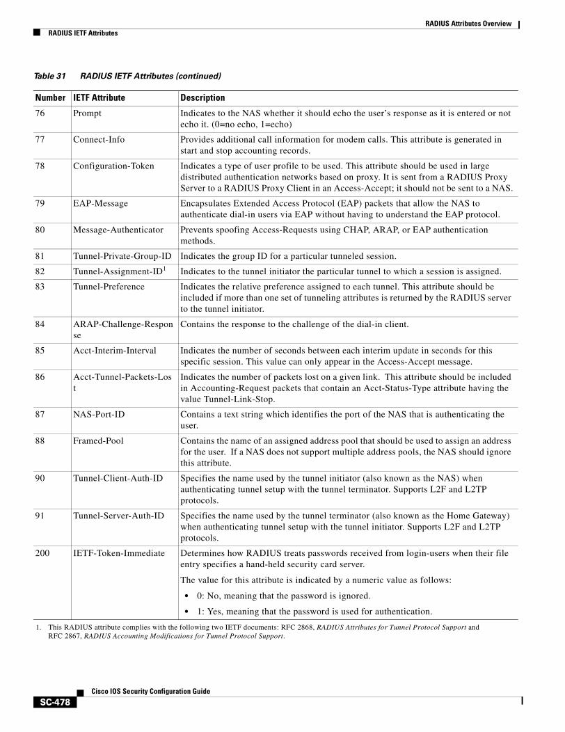
RADIUS Attributes OverviewRADIUS IETF Attributes
SC-478Cisco IOS Security Configuration Guide
76 Prompt Indicates to the NAS whether it should echo the user’s response as it is entered or not echo it. (0=no echo, 1=echo)
77 Connect-Info Provides additional call information for modem calls. This attribute is generated in start and stop accounting records.
78 Configuration-Token Indicates a type of user profile to be used. This attribute should be used in large distributed authentication networks based on proxy. It is sent from a RADIUS Proxy Server to a RADIUS Proxy Client in an Access-Accept; it should not be sent to a NAS.
79 EAP-Message Encapsulates Extended Access Protocol (EAP) packets that allow the NAS to authenticate dial-in users via EAP without having to understand the EAP protocol.
80 Message-Authenticator Prevents spoofing Access-Requests using CHAP, ARAP, or EAP authentication methods.
81 Tunnel-Private-Group-ID Indicates the group ID for a particular tunneled session.
82 Tunnel-Assignment-ID1 Indicates to the tunnel initiator the particular tunnel to which a session is assigned.
83 Tunnel-Preference Indicates the relative preference assigned to each tunnel. This attribute should be included if more than one set of tunneling attributes is returned by the RADIUS server to the tunnel initiator.
84 ARAP-Challenge-Response
Contains the response to the challenge of the dial-in client.
85 Acct-Interim-Interval Indicates the number of seconds between each interim update in seconds for this specific session. This value can only appear in the Access-Accept message.
86 Acct-Tunnel-Packets-Lost
Indicates the number of packets lost on a given link. This attribute should be included in Accounting-Request packets that contain an Acct-Status-Type attribute having the value Tunnel-Link-Stop.
87 NAS-Port-ID Contains a text string which identifies the port of the NAS that is authenticating the user.
88 Framed-Pool Contains the name of an assigned address pool that should be used to assign an address for the user. If a NAS does not support multiple address pools, the NAS should ignore this attribute.
90 Tunnel-Client-Auth-ID Specifies the name used by the tunnel initiator (also known as the NAS) when authenticating tunnel setup with the tunnel terminator. Supports L2F and L2TP protocols.
91 Tunnel-Server-Auth-ID Specifies the name used by the tunnel terminator (also known as the Home Gateway) when authenticating tunnel setup with the tunnel initiator. Supports L2F and L2TP protocols.
200 IETF-Token-Immediate Determines how RADIUS treats passwords received from login-users when their file entry specifies a hand-held security card server.
The value for this attribute is indicated by a numeric value as follows:
• 0: No, meaning that the password is ignored.
• 1: Yes, meaning that the password is used for authentication.
1. This RADIUS attribute complies with the following two IETF documents: RFC 2868, RADIUS Attributes for Tunnel Protocol Support and RFC 2867, RADIUS Accounting Modifications for Tunnel Protocol Support.
Table 31 RADIUS IETF Attributes (continued)
Number IETF Attribute Description
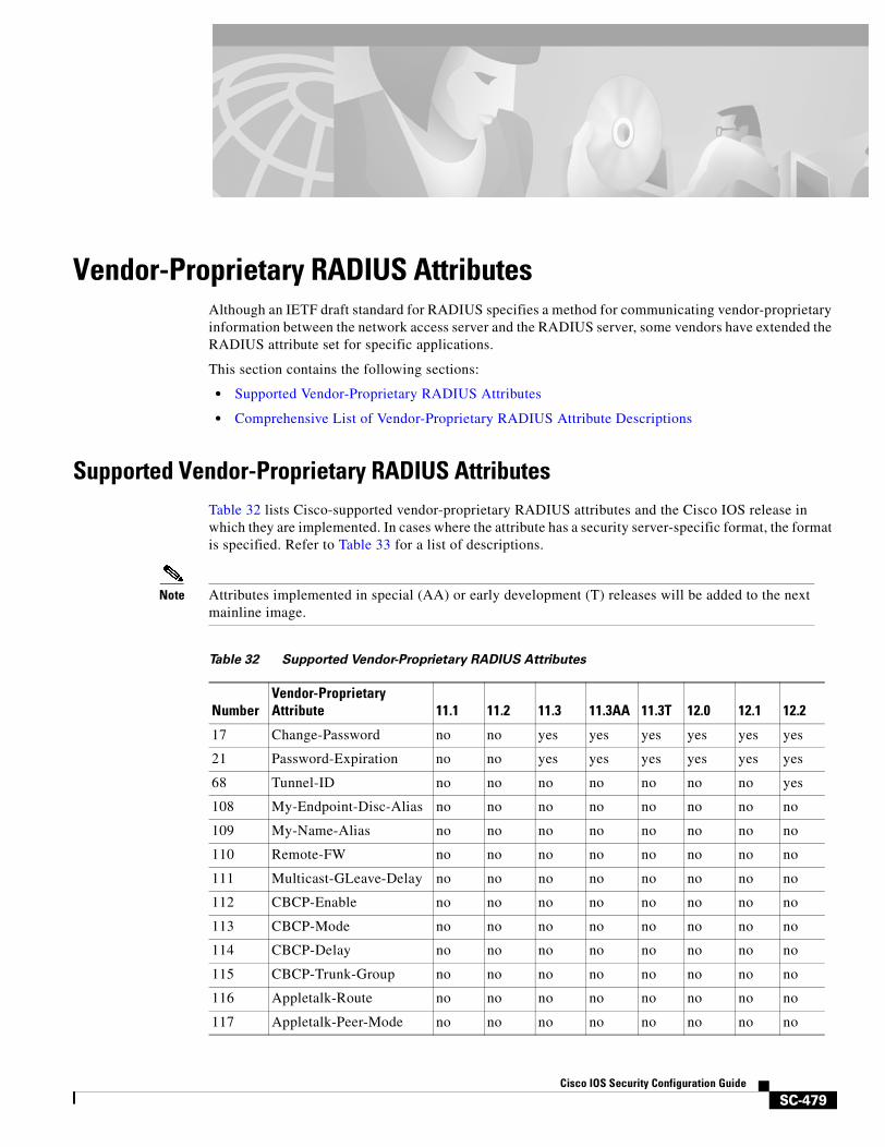
SC-479Cisco IOS Security Configuration Guide
Vendor-Proprietary RADIUS AttributesAlthough an IETF draft standard for RADIUS specifies a method for communicating vendor-proprietary information between the network access server and the RADIUS server, some vendors have extended the RADIUS attribute set for specific applications.
This section contains the following sections:
• Supported Vendor-Proprietary RADIUS Attributes
• Comprehensive List of Vendor-Proprietary RADIUS Attribute Descriptions
Supported Vendor-Proprietary RADIUS AttributesTable 32 lists Cisco-supported vendor-proprietary RADIUS attributes and the Cisco IOS release in which they are implemented. In cases where the attribute has a security server-specific format, the format is specified. Refer to Table 33 for a list of descriptions.
Note Attributes implemented in special (AA) or early development (T) releases will be added to the next mainline image.
Table 32 Supported Vendor-Proprietary RADIUS Attributes
NumberVendor-Proprietary Attribute 11.1 11.2 11.3 11.3AA 11.3T 12.0 12.1 12.2
17 Change-Password no no yes yes yes yes yes yes
21 Password-Expiration no no yes yes yes yes yes yes
68 Tunnel-ID no no no no no no no yes
108 My-Endpoint-Disc-Alias no no no no no no no no
109 My-Name-Alias no no no no no no no no
110 Remote-FW no no no no no no no no
111 Multicast-GLeave-Delay no no no no no no no no
112 CBCP-Enable no no no no no no no no
113 CBCP-Mode no no no no no no no no
114 CBCP-Delay no no no no no no no no
115 CBCP-Trunk-Group no no no no no no no no
116 Appletalk-Route no no no no no no no no
117 Appletalk-Peer-Mode no no no no no no no no
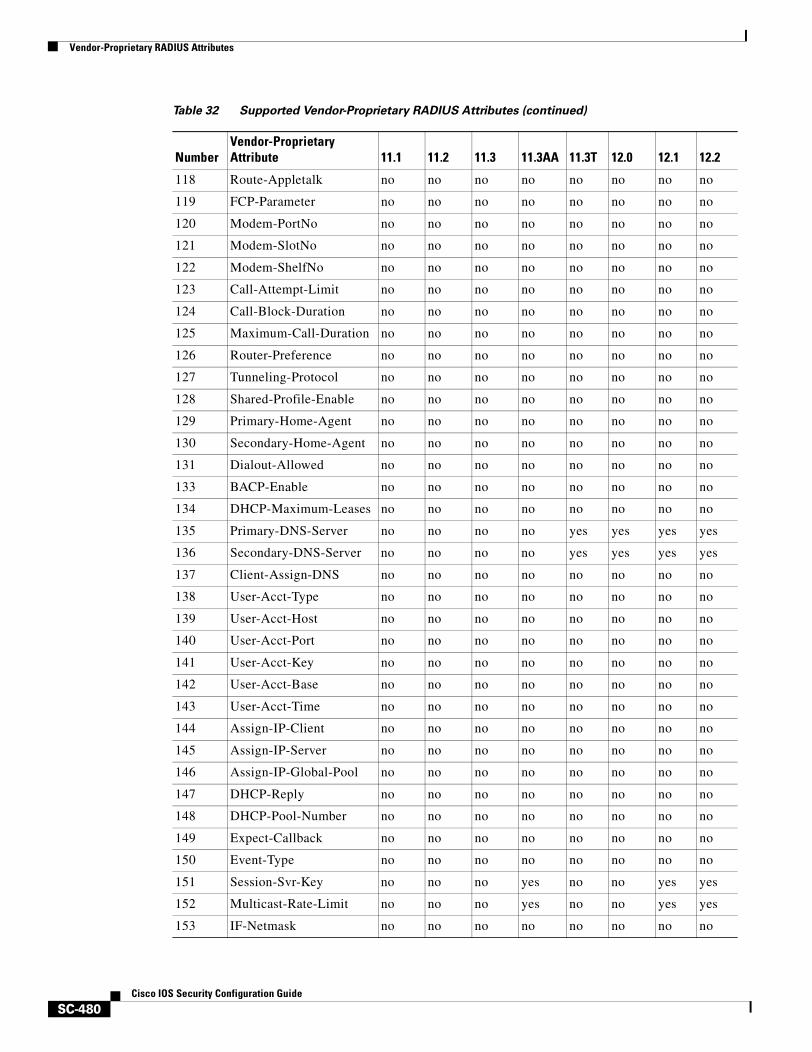
Vendor-Proprietary RADIUS Attributes
SC-480Cisco IOS Security Configuration Guide
118 Route-Appletalk no no no no no no no no
119 FCP-Parameter no no no no no no no no
120 Modem-PortNo no no no no no no no no
121 Modem-SlotNo no no no no no no no no
122 Modem-ShelfNo no no no no no no no no
123 Call-Attempt-Limit no no no no no no no no
124 Call-Block-Duration no no no no no no no no
125 Maximum-Call-Duration no no no no no no no no
126 Router-Preference no no no no no no no no
127 Tunneling-Protocol no no no no no no no no
128 Shared-Profile-Enable no no no no no no no no
129 Primary-Home-Agent no no no no no no no no
130 Secondary-Home-Agent no no no no no no no no
131 Dialout-Allowed no no no no no no no no
133 BACP-Enable no no no no no no no no
134 DHCP-Maximum-Leases no no no no no no no no
135 Primary-DNS-Server no no no no yes yes yes yes
136 Secondary-DNS-Server no no no no yes yes yes yes
137 Client-Assign-DNS no no no no no no no no
138 User-Acct-Type no no no no no no no no
139 User-Acct-Host no no no no no no no no
140 User-Acct-Port no no no no no no no no
141 User-Acct-Key no no no no no no no no
142 User-Acct-Base no no no no no no no no
143 User-Acct-Time no no no no no no no no
144 Assign-IP-Client no no no no no no no no
145 Assign-IP-Server no no no no no no no no
146 Assign-IP-Global-Pool no no no no no no no no
147 DHCP-Reply no no no no no no no no
148 DHCP-Pool-Number no no no no no no no no
149 Expect-Callback no no no no no no no no
150 Event-Type no no no no no no no no
151 Session-Svr-Key no no no yes no no yes yes
152 Multicast-Rate-Limit no no no yes no no yes yes
153 IF-Netmask no no no no no no no no
Table 32 Supported Vendor-Proprietary RADIUS Attributes (continued)
NumberVendor-Proprietary Attribute 11.1 11.2 11.3 11.3AA 11.3T 12.0 12.1 12.2
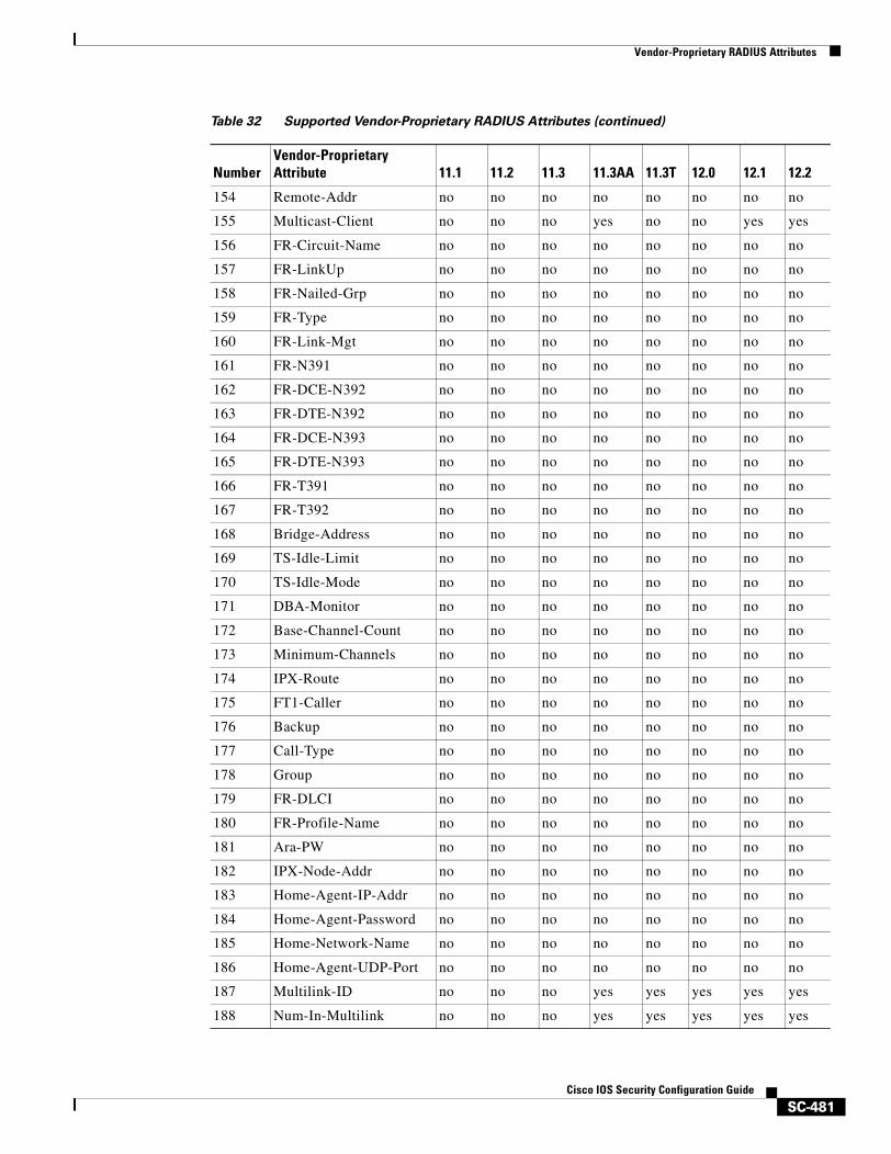
Vendor-Proprietary RADIUS Attributes
SC-481Cisco IOS Security Configuration Guide
154 Remote-Addr no no no no no no no no
155 Multicast-Client no no no yes no no yes yes
156 FR-Circuit-Name no no no no no no no no
157 FR-LinkUp no no no no no no no no
158 FR-Nailed-Grp no no no no no no no no
159 FR-Type no no no no no no no no
160 FR-Link-Mgt no no no no no no no no
161 FR-N391 no no no no no no no no
162 FR-DCE-N392 no no no no no no no no
163 FR-DTE-N392 no no no no no no no no
164 FR-DCE-N393 no no no no no no no no
165 FR-DTE-N393 no no no no no no no no
166 FR-T391 no no no no no no no no
167 FR-T392 no no no no no no no no
168 Bridge-Address no no no no no no no no
169 TS-Idle-Limit no no no no no no no no
170 TS-Idle-Mode no no no no no no no no
171 DBA-Monitor no no no no no no no no
172 Base-Channel-Count no no no no no no no no
173 Minimum-Channels no no no no no no no no
174 IPX-Route no no no no no no no no
175 FT1-Caller no no no no no no no no
176 Backup no no no no no no no no
177 Call-Type no no no no no no no no
178 Group no no no no no no no no
179 FR-DLCI no no no no no no no no
180 FR-Profile-Name no no no no no no no no
181 Ara-PW no no no no no no no no
182 IPX-Node-Addr no no no no no no no no
183 Home-Agent-IP-Addr no no no no no no no no
184 Home-Agent-Password no no no no no no no no
185 Home-Network-Name no no no no no no no no
186 Home-Agent-UDP-Port no no no no no no no no
187 Multilink-ID no no no yes yes yes yes yes
188 Num-In-Multilink no no no yes yes yes yes yes
Table 32 Supported Vendor-Proprietary RADIUS Attributes (continued)
NumberVendor-Proprietary Attribute 11.1 11.2 11.3 11.3AA 11.3T 12.0 12.1 12.2
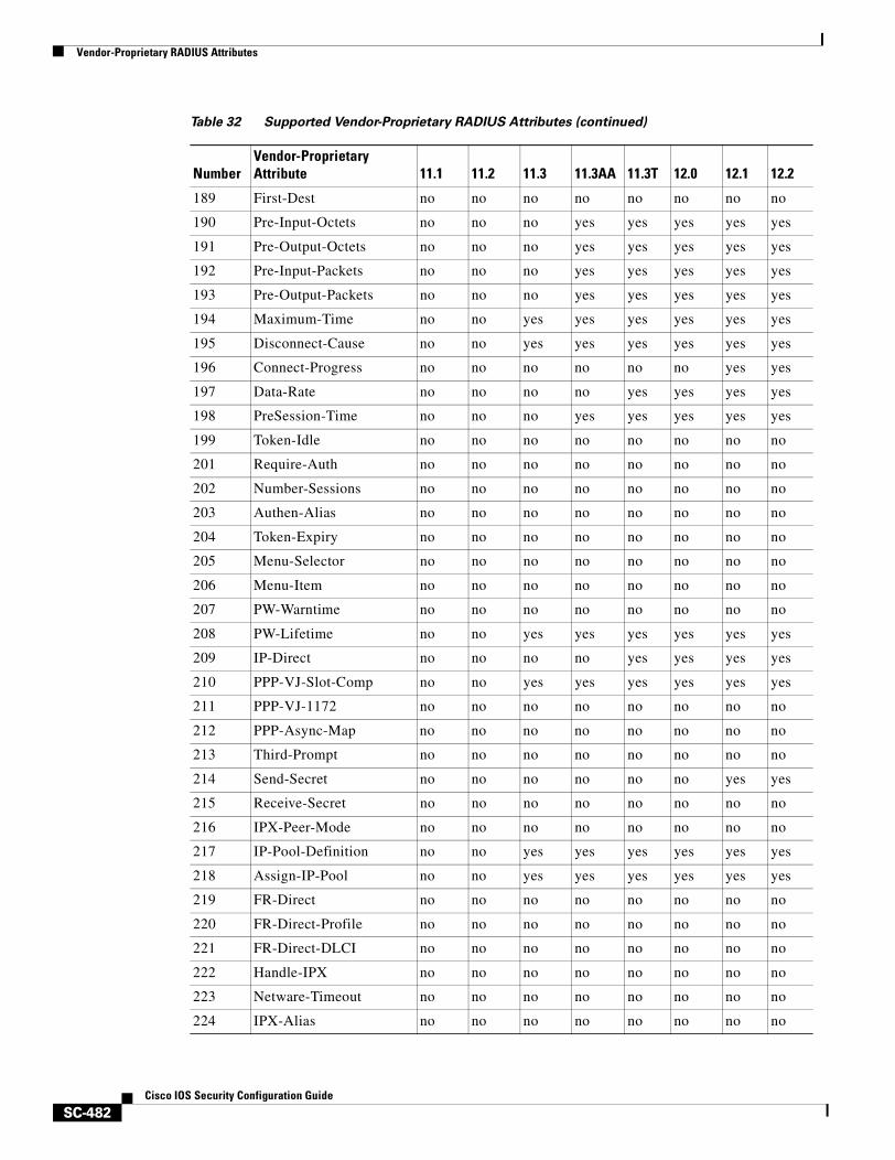
Vendor-Proprietary RADIUS Attributes
SC-482Cisco IOS Security Configuration Guide
189 First-Dest no no no no no no no no
190 Pre-Input-Octets no no no yes yes yes yes yes
191 Pre-Output-Octets no no no yes yes yes yes yes
192 Pre-Input-Packets no no no yes yes yes yes yes
193 Pre-Output-Packets no no no yes yes yes yes yes
194 Maximum-Time no no yes yes yes yes yes yes
195 Disconnect-Cause no no yes yes yes yes yes yes
196 Connect-Progress no no no no no no yes yes
197 Data-Rate no no no no yes yes yes yes
198 PreSession-Time no no no yes yes yes yes yes
199 Token-Idle no no no no no no no no
201 Require-Auth no no no no no no no no
202 Number-Sessions no no no no no no no no
203 Authen-Alias no no no no no no no no
204 Token-Expiry no no no no no no no no
205 Menu-Selector no no no no no no no no
206 Menu-Item no no no no no no no no
207 PW-Warntime no no no no no no no no
208 PW-Lifetime no no yes yes yes yes yes yes
209 IP-Direct no no no no yes yes yes yes
210 PPP-VJ-Slot-Comp no no yes yes yes yes yes yes
211 PPP-VJ-1172 no no no no no no no no
212 PPP-Async-Map no no no no no no no no
213 Third-Prompt no no no no no no no no
214 Send-Secret no no no no no no yes yes
215 Receive-Secret no no no no no no no no
216 IPX-Peer-Mode no no no no no no no no
217 IP-Pool-Definition no no yes yes yes yes yes yes
218 Assign-IP-Pool no no yes yes yes yes yes yes
219 FR-Direct no no no no no no no no
220 FR-Direct-Profile no no no no no no no no
221 FR-Direct-DLCI no no no no no no no no
222 Handle-IPX no no no no no no no no
223 Netware-Timeout no no no no no no no no
224 IPX-Alias no no no no no no no no
Table 32 Supported Vendor-Proprietary RADIUS Attributes (continued)
NumberVendor-Proprietary Attribute 11.1 11.2 11.3 11.3AA 11.3T 12.0 12.1 12.2
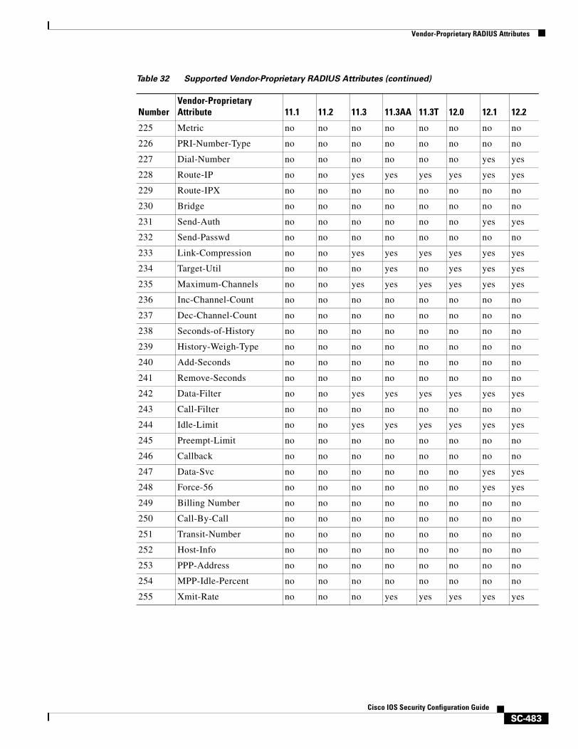
Vendor-Proprietary RADIUS Attributes
SC-483Cisco IOS Security Configuration Guide
225 Metric no no no no no no no no
226 PRI-Number-Type no no no no no no no no
227 Dial-Number no no no no no no yes yes
228 Route-IP no no yes yes yes yes yes yes
229 Route-IPX no no no no no no no no
230 Bridge no no no no no no no no
231 Send-Auth no no no no no no yes yes
232 Send-Passwd no no no no no no no no
233 Link-Compression no no yes yes yes yes yes yes
234 Target-Util no no no yes no yes yes yes
235 Maximum-Channels no no yes yes yes yes yes yes
236 Inc-Channel-Count no no no no no no no no
237 Dec-Channel-Count no no no no no no no no
238 Seconds-of-History no no no no no no no no
239 History-Weigh-Type no no no no no no no no
240 Add-Seconds no no no no no no no no
241 Remove-Seconds no no no no no no no no
242 Data-Filter no no yes yes yes yes yes yes
243 Call-Filter no no no no no no no no
244 Idle-Limit no no yes yes yes yes yes yes
245 Preempt-Limit no no no no no no no no
246 Callback no no no no no no no no
247 Data-Svc no no no no no no yes yes
248 Force-56 no no no no no no yes yes
249 Billing Number no no no no no no no no
250 Call-By-Call no no no no no no no no
251 Transit-Number no no no no no no no no
252 Host-Info no no no no no no no no
253 PPP-Address no no no no no no no no
254 MPP-Idle-Percent no no no no no no no no
255 Xmit-Rate no no no yes yes yes yes yes
Table 32 Supported Vendor-Proprietary RADIUS Attributes (continued)
NumberVendor-Proprietary Attribute 11.1 11.2 11.3 11.3AA 11.3T 12.0 12.1 12.2
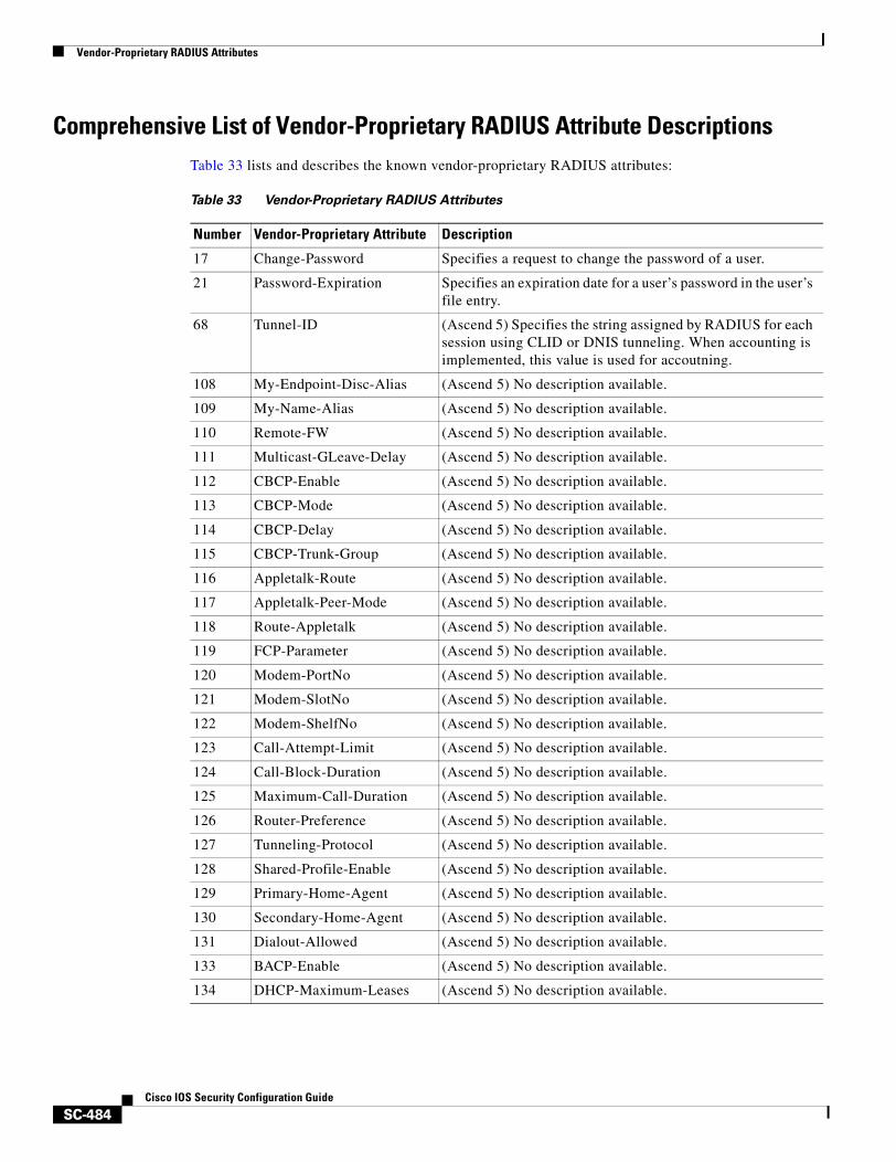
Vendor-Proprietary RADIUS Attributes
SC-484Cisco IOS Security Configuration Guide
Comprehensive List of Vendor-Proprietary RADIUS Attribute DescriptionsTable 33 lists and describes the known vendor-proprietary RADIUS attributes:
Table 33 Vendor-Proprietary RADIUS Attributes
Number Vendor-Proprietary Attribute Description
17 Change-Password Specifies a request to change the password of a user.
21 Password-Expiration Specifies an expiration date for a user’s password in the user’s file entry.
68 Tunnel-ID (Ascend 5) Specifies the string assigned by RADIUS for each session using CLID or DNIS tunneling. When accounting is implemented, this value is used for accoutning.
108 My-Endpoint-Disc-Alias (Ascend 5) No description available.
109 My-Name-Alias (Ascend 5) No description available.
110 Remote-FW (Ascend 5) No description available.
111 Multicast-GLeave-Delay (Ascend 5) No description available.
112 CBCP-Enable (Ascend 5) No description available.
113 CBCP-Mode (Ascend 5) No description available.
114 CBCP-Delay (Ascend 5) No description available.
115 CBCP-Trunk-Group (Ascend 5) No description available.
116 Appletalk-Route (Ascend 5) No description available.
117 Appletalk-Peer-Mode (Ascend 5) No description available.
118 Route-Appletalk (Ascend 5) No description available.
119 FCP-Parameter (Ascend 5) No description available.
120 Modem-PortNo (Ascend 5) No description available.
121 Modem-SlotNo (Ascend 5) No description available.
122 Modem-ShelfNo (Ascend 5) No description available.
123 Call-Attempt-Limit (Ascend 5) No description available.
124 Call-Block-Duration (Ascend 5) No description available.
125 Maximum-Call-Duration (Ascend 5) No description available.
126 Router-Preference (Ascend 5) No description available.
127 Tunneling-Protocol (Ascend 5) No description available.
128 Shared-Profile-Enable (Ascend 5) No description available.
129 Primary-Home-Agent (Ascend 5) No description available.
130 Secondary-Home-Agent (Ascend 5) No description available.
131 Dialout-Allowed (Ascend 5) No description available.
133 BACP-Enable (Ascend 5) No description available.
134 DHCP-Maximum-Leases (Ascend 5) No description available.
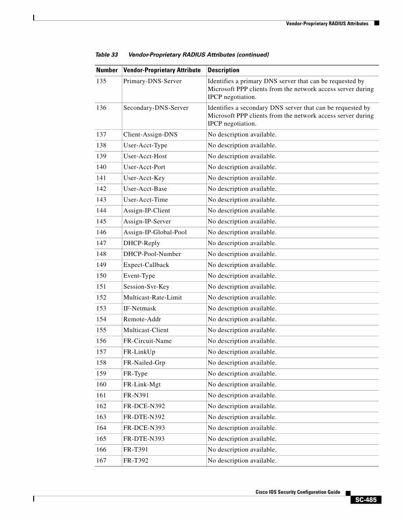
Vendor-Proprietary RADIUS Attributes
SC-485Cisco IOS Security Configuration Guide
135 Primary-DNS-Server Identifies a primary DNS server that can be requested by Microsoft PPP clients from the network access server during IPCP negotiation.
136 Secondary-DNS-Server Identifies a secondary DNS server that can be requested by Microsoft PPP clients from the network access server during IPCP negotiation.
137 Client-Assign-DNS No description available.
138 User-Acct-Type No description available.
139 User-Acct-Host No description available.
140 User-Acct-Port No description available.
141 User-Acct-Key No description available.
142 User-Acct-Base No description available.
143 User-Acct-Time No description available.
144 Assign-IP-Client No description available.
145 Assign-IP-Server No description available.
146 Assign-IP-Global-Pool No description available.
147 DHCP-Reply No description available.
148 DHCP-Pool-Number No description available.
149 Expect-Callback No description available.
150 Event-Type No description available.
151 Session-Svr-Key No description available.
152 Multicast-Rate-Limit No description available.
153 IF-Netmask No description available.
154 Remote-Addr No description available.
155 Multicast-Client No description available.
156 FR-Circuit-Name No description available.
157 FR-LinkUp No description available.
158 FR-Nailed-Grp No description available.
159 FR-Type No description available.
160 FR-Link-Mgt No description available.
161 FR-N391 No description available.
162 FR-DCE-N392 No description available.
163 FR-DTE-N392 No description available.
164 FR-DCE-N393 No description available.
165 FR-DTE-N393 No description available.
166 FR-T391 No description available.
167 FR-T392 No description available.
Table 33 Vendor-Proprietary RADIUS Attributes (continued)
Number Vendor-Proprietary Attribute Description
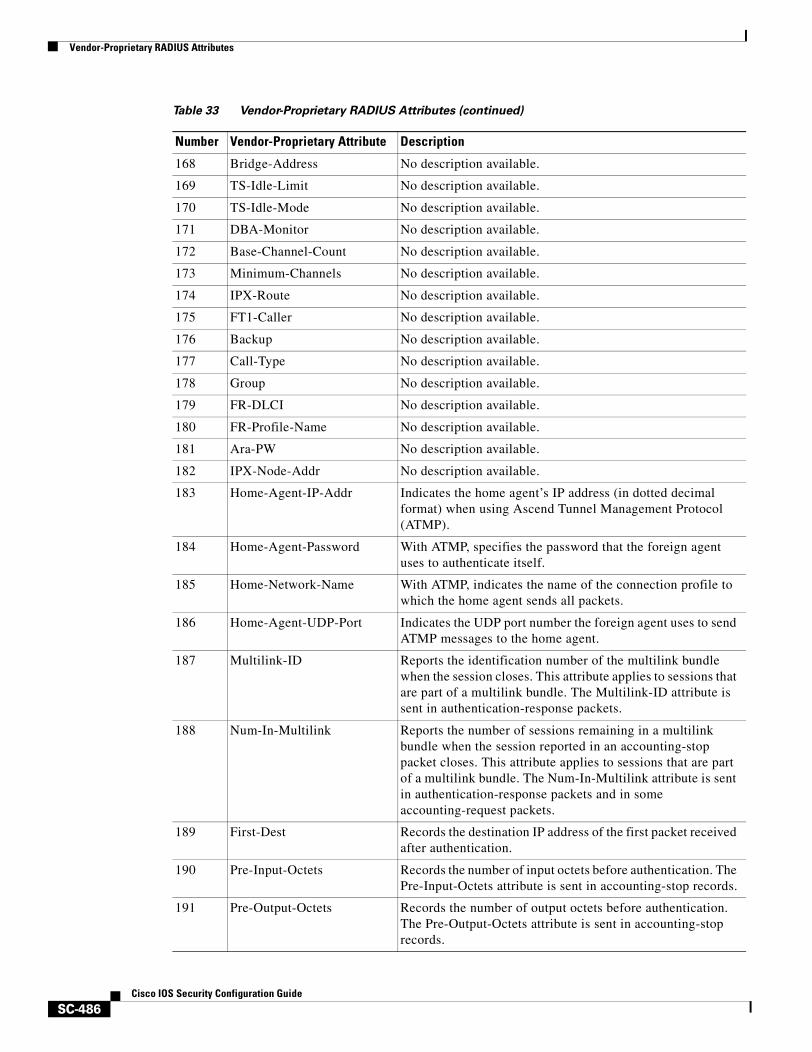
Vendor-Proprietary RADIUS Attributes
SC-486Cisco IOS Security Configuration Guide
168 Bridge-Address No description available.
169 TS-Idle-Limit No description available.
170 TS-Idle-Mode No description available.
171 DBA-Monitor No description available.
172 Base-Channel-Count No description available.
173 Minimum-Channels No description available.
174 IPX-Route No description available.
175 FT1-Caller No description available.
176 Backup No description available.
177 Call-Type No description available.
178 Group No description available.
179 FR-DLCI No description available.
180 FR-Profile-Name No description available.
181 Ara-PW No description available.
182 IPX-Node-Addr No description available.
183 Home-Agent-IP-Addr Indicates the home agent’s IP address (in dotted decimal format) when using Ascend Tunnel Management Protocol (ATMP).
184 Home-Agent-Password With ATMP, specifies the password that the foreign agent uses to authenticate itself.
185 Home-Network-Name With ATMP, indicates the name of the connection profile to which the home agent sends all packets.
186 Home-Agent-UDP-Port Indicates the UDP port number the foreign agent uses to send ATMP messages to the home agent.
187 Multilink-ID Reports the identification number of the multilink bundle when the session closes. This attribute applies to sessions that are part of a multilink bundle. The Multilink-ID attribute is sent in authentication-response packets.
188 Num-In-Multilink Reports the number of sessions remaining in a multilink bundle when the session reported in an accounting-stop packet closes. This attribute applies to sessions that are part of a multilink bundle. The Num-In-Multilink attribute is sent in authentication-response packets and in some accounting-request packets.
189 First-Dest Records the destination IP address of the first packet received after authentication.
190 Pre-Input-Octets Records the number of input octets before authentication. The Pre-Input-Octets attribute is sent in accounting-stop records.
191 Pre-Output-Octets Records the number of output octets before authentication. The Pre-Output-Octets attribute is sent in accounting-stop records.
Table 33 Vendor-Proprietary RADIUS Attributes (continued)
Number Vendor-Proprietary Attribute Description
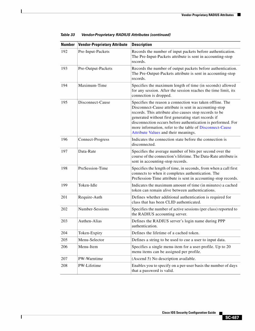
Vendor-Proprietary RADIUS Attributes
SC-487Cisco IOS Security Configuration Guide
192 Pre-Input-Packets Records the number of input packets before authentication. The Pre-Input-Packets attribute is sent in accounting-stop records.
193 Pre-Output-Packets Records the number of output packets before authentication. The Pre-Output-Packets attribute is sent in accounting-stop records.
194 Maximum-Time Specifies the maximum length of time (in seconds) allowed for any session. After the session reaches the time limit, its connection is dropped.
195 Disconnect-Cause Specifies the reason a connection was taken offline. The Disconnect-Cause attribute is sent in accounting-stop records. This attribute also causes stop records to be generated without first generating start records if disconnection occurs before authentication is performed. For more information, refer to the table of Disconnect-Cause Attribute Values and their meanings.
196 Connect-Progress Indicates the connection state before the connection is disconnected.
197 Data-Rate Specifies the average number of bits per second over the course of the connection’s lifetime. The Data-Rate attribute is sent in accounting-stop records.
198 PreSession-Time Specifies the length of time, in seconds, from when a call first connects to when it completes authentication. The PreSession-Time attribute is sent in accounting-stop records.
199 Token-Idle Indicates the maximum amount of time (in minutes) a cached token can remain alive between authentications.
201 Require-Auth Defines whether additional authentication is required for class that has been CLID authenticated.
202 Number-Sessions Specifies the number of active sessions (per class) reported to the RADIUS accounting server.
203 Authen-Alias Defines the RADIUS server’s login name during PPP authentication.
204 Token-Expiry Defines the lifetime of a cached token.
205 Menu-Selector Defines a string to be used to cue a user to input data.
206 Menu-Item Specifies a single menu-item for a user-profile. Up to 20 menu items can be assigned per profile.
207 PW-Warntime (Ascend 5) No description available.
208 PW-Lifetime Enables you to specify on a per-user basis the number of days that a password is valid.
Table 33 Vendor-Proprietary RADIUS Attributes (continued)
Number Vendor-Proprietary Attribute Description
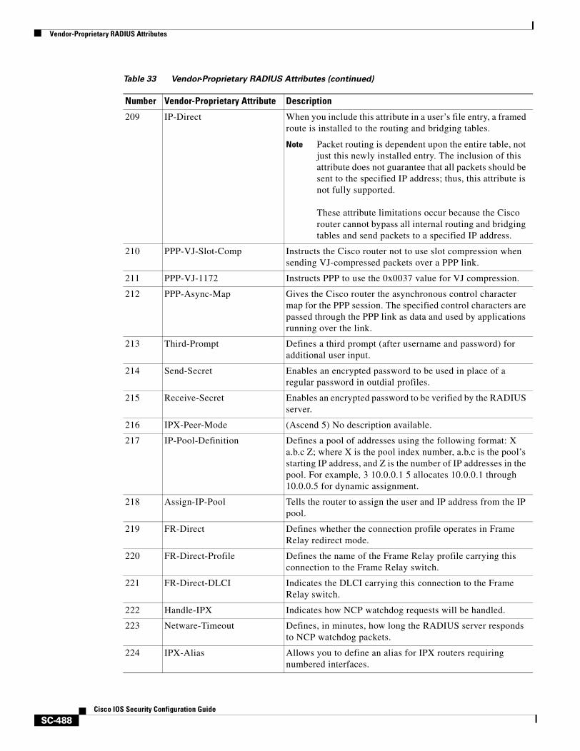
Vendor-Proprietary RADIUS Attributes
SC-488Cisco IOS Security Configuration Guide
209 IP-Direct When you include this attribute in a user’s file entry, a framed route is installed to the routing and bridging tables.
Note Packet routing is dependent upon the entire table, not just this newly installed entry. The inclusion of this attribute does not guarantee that all packets should be sent to the specified IP address; thus, this attribute is not fully supported.
These attribute limitations occur because the Cisco router cannot bypass all internal routing and bridging tables and send packets to a specified IP address.
210 PPP-VJ-Slot-Comp Instructs the Cisco router not to use slot compression when sending VJ-compressed packets over a PPP link.
211 PPP-VJ-1172 Instructs PPP to use the 0x0037 value for VJ compression.
212 PPP-Async-Map Gives the Cisco router the asynchronous control character map for the PPP session. The specified control characters are passed through the PPP link as data and used by applications running over the link.
213 Third-Prompt Defines a third prompt (after username and password) for additional user input.
214 Send-Secret Enables an encrypted password to be used in place of a regular password in outdial profiles.
215 Receive-Secret Enables an encrypted password to be verified by the RADIUS server.
216 IPX-Peer-Mode (Ascend 5) No description available.
217 IP-Pool-Definition Defines a pool of addresses using the following format: X a.b.c Z; where X is the pool index number, a.b.c is the pool’s starting IP address, and Z is the number of IP addresses in the pool. For example, 3 10.0.0.1 5 allocates 10.0.0.1 through 10.0.0.5 for dynamic assignment.
218 Assign-IP-Pool Tells the router to assign the user and IP address from the IP pool.
219 FR-Direct Defines whether the connection profile operates in Frame Relay redirect mode.
220 FR-Direct-Profile Defines the name of the Frame Relay profile carrying this connection to the Frame Relay switch.
221 FR-Direct-DLCI Indicates the DLCI carrying this connection to the Frame Relay switch.
222 Handle-IPX Indicates how NCP watchdog requests will be handled.
223 Netware-Timeout Defines, in minutes, how long the RADIUS server responds to NCP watchdog packets.
224 IPX-Alias Allows you to define an alias for IPX routers requiring numbered interfaces.
Table 33 Vendor-Proprietary RADIUS Attributes (continued)
Number Vendor-Proprietary Attribute Description
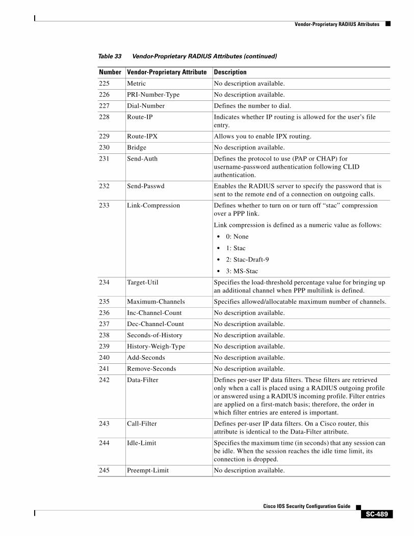
Vendor-Proprietary RADIUS Attributes
SC-489Cisco IOS Security Configuration Guide
225 Metric No description available.
226 PRI-Number-Type No description available.
227 Dial-Number Defines the number to dial.
228 Route-IP Indicates whether IP routing is allowed for the user’s file entry.
229 Route-IPX Allows you to enable IPX routing.
230 Bridge No description available.
231 Send-Auth Defines the protocol to use (PAP or CHAP) for username-password authentication following CLID authentication.
232 Send-Passwd Enables the RADIUS server to specify the password that is sent to the remote end of a connection on outgoing calls.
233 Link-Compression Defines whether to turn on or turn off “stac” compression over a PPP link.
Link compression is defined as a numeric value as follows:
• 0: None
• 1: Stac
• 2: Stac-Draft-9
• 3: MS-Stac
234 Target-Util Specifies the load-threshold percentage value for bringing up an additional channel when PPP multilink is defined.
235 Maximum-Channels Specifies allowed/allocatable maximum number of channels.
236 Inc-Channel-Count No description available.
237 Dec-Channel-Count No description available.
238 Seconds-of-History No description available.
239 History-Weigh-Type No description available.
240 Add-Seconds No description available.
241 Remove-Seconds No description available.
242 Data-Filter Defines per-user IP data filters. These filters are retrieved only when a call is placed using a RADIUS outgoing profile or answered using a RADIUS incoming profile. Filter entries are applied on a first-match basis; therefore, the order in which filter entries are entered is important.
243 Call-Filter Defines per-user IP data filters. On a Cisco router, this attribute is identical to the Data-Filter attribute.
244 Idle-Limit Specifies the maximum time (in seconds) that any session can be idle. When the session reaches the idle time limit, its connection is dropped.
245 Preempt-Limit No description available.
Table 33 Vendor-Proprietary RADIUS Attributes (continued)
Number Vendor-Proprietary Attribute Description
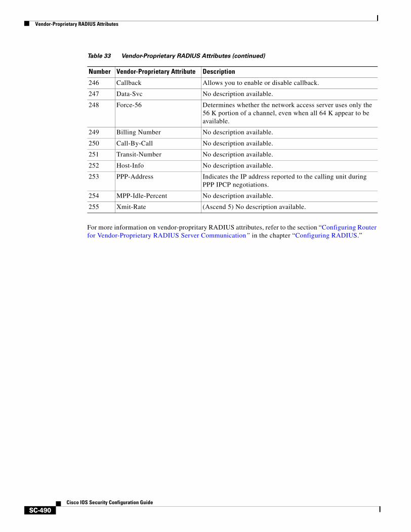
Vendor-Proprietary RADIUS Attributes
SC-490Cisco IOS Security Configuration Guide
For more information on vendor-propritary RADIUS attributes, refer to the section “Configuring Router for Vendor-Proprietary RADIUS Server Communication” in the chapter “Configuring RADIUS.”
246 Callback Allows you to enable or disable callback.
247 Data-Svc No description available.
248 Force-56 Determines whether the network access server uses only the 56 K portion of a channel, even when all 64 K appear to be available.
249 Billing Number No description available.
250 Call-By-Call No description available.
251 Transit-Number No description available.
252 Host-Info No description available.
253 PPP-Address Indicates the IP address reported to the calling unit during PPP IPCP negotiations.
254 MPP-Idle-Percent No description available.
255 Xmit-Rate (Ascend 5) No description available.
Table 33 Vendor-Proprietary RADIUS Attributes (continued)
Number Vendor-Proprietary Attribute Description
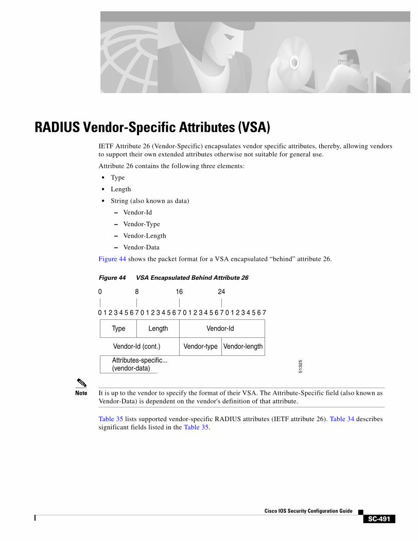
SC-491Cisco IOS Security Configuration Guide
RADIUS Vendor-Specific Attributes (VSA)IETF Attribute 26 (Vendor-Specific) encapsulates vendor specific attributes, thereby, allowing vendors to support their own extended attributes otherwise not suitable for general use.
Attribute 26 contains the following three elements:
• Type
• Length
• String (also known as data)
– Vendor-Id
– Vendor-Type
– Vendor-Length
– Vendor-Data
Figure 44 shows the packet format for a VSA encapsulated “behind” attribute 26.
Figure 44 VSA Encapsulated Behind Attribute 26
Note It is up to the vendor to specify the format of their VSA. The Attribute-Specific field (also known as Vendor-Data) is dependent on the vendor's definition of that attribute.
Table 35 lists supported vendor-specific RADIUS attributes (IETF attribute 26). Table 34 describes significant fields listed in the Table 35.
0 1 2 3 4 5 6 7 0 1 2 3 4 5 6 7 0 1 2 3 4 5 6 7 0 1 2 3 4 5 6 7
0 8
Type
Attributes-specific...(vendor-data)
Length Vendor-Id
Vendor-Id (cont.) Vendor-type Vendor-length
16 2451325
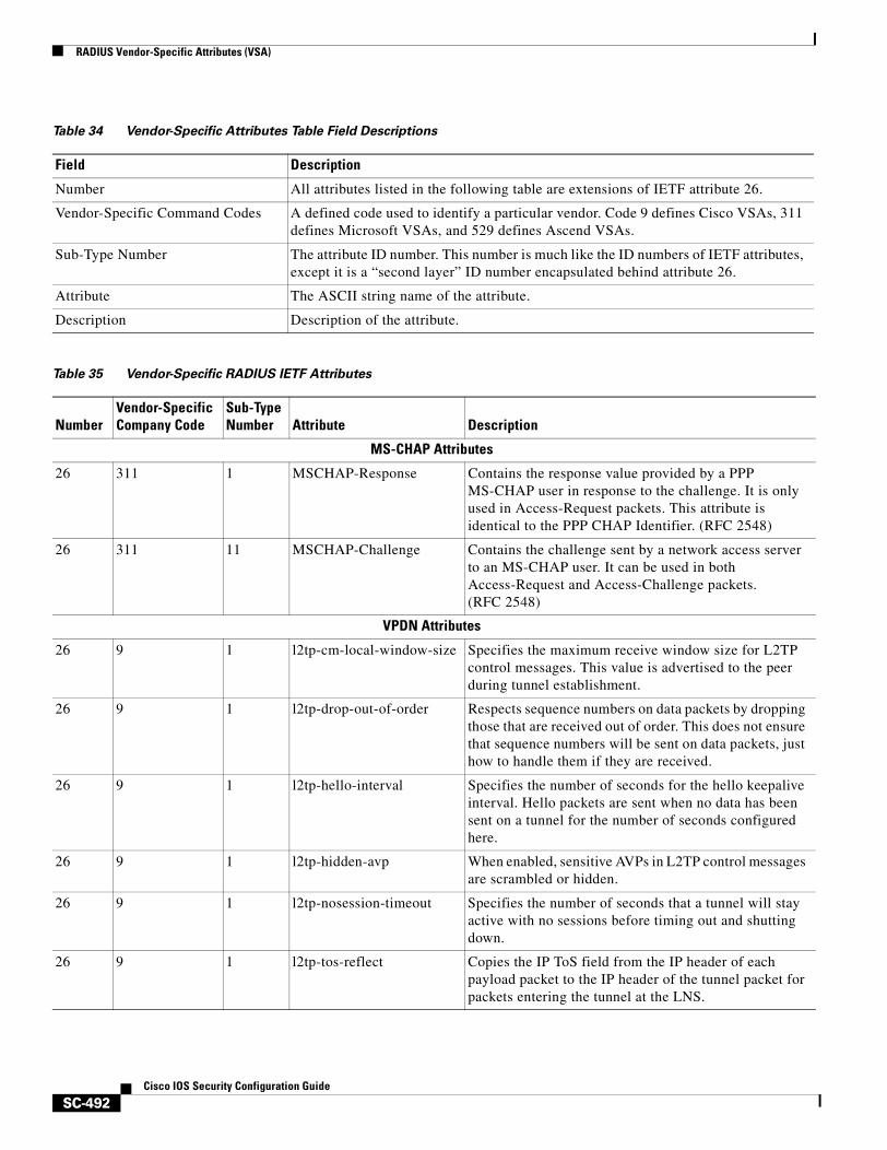
RADIUS Vendor-Specific Attributes (VSA)
SC-492Cisco IOS Security Configuration Guide
Table 34 Vendor-Specific Attributes Table Field Descriptions
Field Description
Number All attributes listed in the following table are extensions of IETF attribute 26.
Vendor-Specific Command Codes A defined code used to identify a particular vendor. Code 9 defines Cisco VSAs, 311 defines Microsoft VSAs, and 529 defines Ascend VSAs.
Sub-Type Number The attribute ID number. This number is much like the ID numbers of IETF attributes, except it is a “second layer” ID number encapsulated behind attribute 26.
Attribute The ASCII string name of the attribute.
Description Description of the attribute.
Table 35 Vendor-Specific RADIUS IETF Attributes
NumberVendor-SpecificCompany Code
Sub-TypeNumber Attribute Description
MS-CHAP Attributes
26 311 1 MSCHAP-Response Contains the response value provided by a PPP MS-CHAP user in response to the challenge. It is only used in Access-Request packets. This attribute is identical to the PPP CHAP Identifier. (RFC 2548)
26 311 11 MSCHAP-Challenge Contains the challenge sent by a network access server to an MS-CHAP user. It can be used in both Access-Request and Access-Challenge packets. (RFC 2548)
VPDN Attributes
26 9 1 l2tp-cm-local-window-size Specifies the maximum receive window size for L2TP control messages. This value is advertised to the peer during tunnel establishment.
26 9 1 l2tp-drop-out-of-order Respects sequence numbers on data packets by dropping those that are received out of order. This does not ensure that sequence numbers will be sent on data packets, just how to handle them if they are received.
26 9 1 l2tp-hello-interval Specifies the number of seconds for the hello keepalive interval. Hello packets are sent when no data has been sent on a tunnel for the number of seconds configured here.
26 9 1 l2tp-hidden-avp When enabled, sensitive AVPs in L2TP control messages are scrambled or hidden.
26 9 1 l2tp-nosession-timeout Specifies the number of seconds that a tunnel will stay active with no sessions before timing out and shutting down.
26 9 1 l2tp-tos-reflect Copies the IP ToS field from the IP header of each payload packet to the IP header of the tunnel packet for packets entering the tunnel at the LNS.
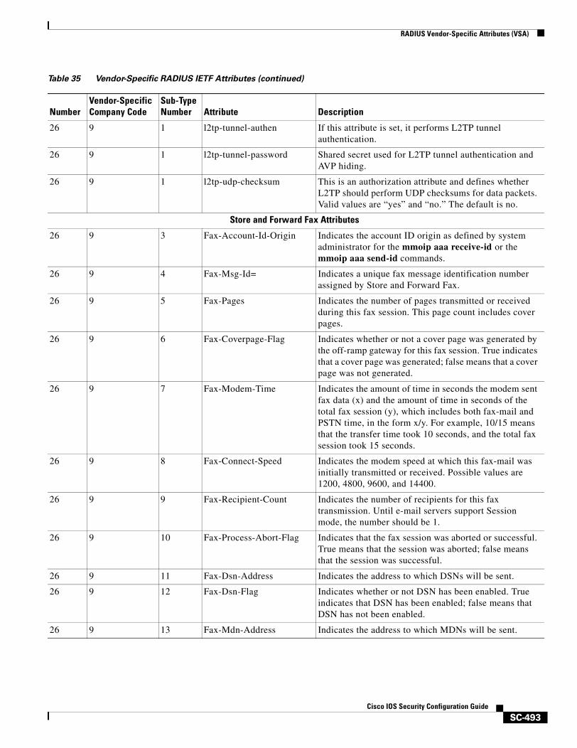
RADIUS Vendor-Specific Attributes (VSA)
SC-493Cisco IOS Security Configuration Guide
26 9 1 l2tp-tunnel-authen If this attribute is set, it performs L2TP tunnel authentication.
26 9 1 l2tp-tunnel-password Shared secret used for L2TP tunnel authentication and AVP hiding.
26 9 1 l2tp-udp-checksum This is an authorization attribute and defines whether L2TP should perform UDP checksums for data packets. Valid values are “yes” and “no.” The default is no.
Store and Forward Fax Attributes
26 9 3 Fax-Account-Id-Origin Indicates the account ID origin as defined by system administrator for the mmoip aaa receive-id or the mmoip aaa send-id commands.
26 9 4 Fax-Msg-Id= Indicates a unique fax message identification number assigned by Store and Forward Fax.
26 9 5 Fax-Pages Indicates the number of pages transmitted or received during this fax session. This page count includes cover pages.
26 9 6 Fax-Coverpage-Flag Indicates whether or not a cover page was generated by the off-ramp gateway for this fax session. True indicates that a cover page was generated; false means that a cover page was not generated.
26 9 7 Fax-Modem-Time Indicates the amount of time in seconds the modem sent fax data (x) and the amount of time in seconds of the total fax session (y), which includes both fax-mail and PSTN time, in the form x/y. For example, 10/15 means that the transfer time took 10 seconds, and the total fax session took 15 seconds.
26 9 8 Fax-Connect-Speed Indicates the modem speed at which this fax-mail was initially transmitted or received. Possible values are 1200, 4800, 9600, and 14400.
26 9 9 Fax-Recipient-Count Indicates the number of recipients for this fax transmission. Until e-mail servers support Session mode, the number should be 1.
26 9 10 Fax-Process-Abort-Flag Indicates that the fax session was aborted or successful. True means that the session was aborted; false means that the session was successful.
26 9 11 Fax-Dsn-Address Indicates the address to which DSNs will be sent.
26 9 12 Fax-Dsn-Flag Indicates whether or not DSN has been enabled. True indicates that DSN has been enabled; false means that DSN has not been enabled.
26 9 13 Fax-Mdn-Address Indicates the address to which MDNs will be sent.
Table 35 Vendor-Specific RADIUS IETF Attributes (continued)
NumberVendor-SpecificCompany Code
Sub-TypeNumber Attribute Description
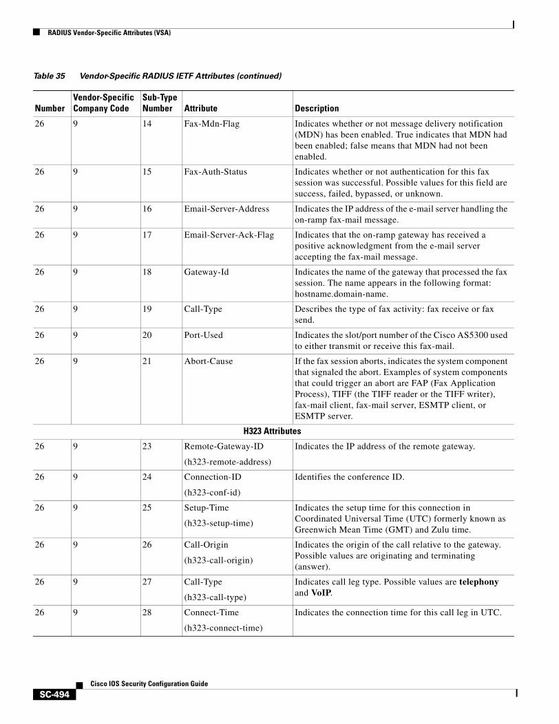
RADIUS Vendor-Specific Attributes (VSA)
SC-494Cisco IOS Security Configuration Guide
26 9 14 Fax-Mdn-Flag Indicates whether or not message delivery notification (MDN) has been enabled. True indicates that MDN had been enabled; false means that MDN had not been enabled.
26 9 15 Fax-Auth-Status Indicates whether or not authentication for this fax session was successful. Possible values for this field are success, failed, bypassed, or unknown.
26 9 16 Email-Server-Address Indicates the IP address of the e-mail server handling the on-ramp fax-mail message.
26 9 17 Email-Server-Ack-Flag Indicates that the on-ramp gateway has received a positive acknowledgment from the e-mail server accepting the fax-mail message.
26 9 18 Gateway-Id Indicates the name of the gateway that processed the fax session. The name appears in the following format: hostname.domain-name.
26 9 19 Call-Type Describes the type of fax activity: fax receive or fax send.
26 9 20 Port-Used Indicates the slot/port number of the Cisco AS5300 used to either transmit or receive this fax-mail.
26 9 21 Abort-Cause If the fax session aborts, indicates the system component that signaled the abort. Examples of system components that could trigger an abort are FAP (Fax Application Process), TIFF (the TIFF reader or the TIFF writer), fax-mail client, fax-mail server, ESMTP client, or ESMTP server.
H323 Attributes
26 9 23 Remote-Gateway-ID
(h323-remote-address)
Indicates the IP address of the remote gateway.
26 9 24 Connection-ID
(h323-conf-id)
Identifies the conference ID.
26 9 25 Setup-Time
(h323-setup-time)
Indicates the setup time for this connection in Coordinated Universal Time (UTC) formerly known as Greenwich Mean Time (GMT) and Zulu time.
26 9 26 Call-Origin
(h323-call-origin)
Indicates the origin of the call relative to the gateway. Possible values are originating and terminating (answer).
26 9 27 Call-Type
(h323-call-type)
Indicates call leg type. Possible values are telephony and VoIP.
26 9 28 Connect-Time
(h323-connect-time)
Indicates the connection time for this call leg in UTC.
Table 35 Vendor-Specific RADIUS IETF Attributes (continued)
NumberVendor-SpecificCompany Code
Sub-TypeNumber Attribute Description
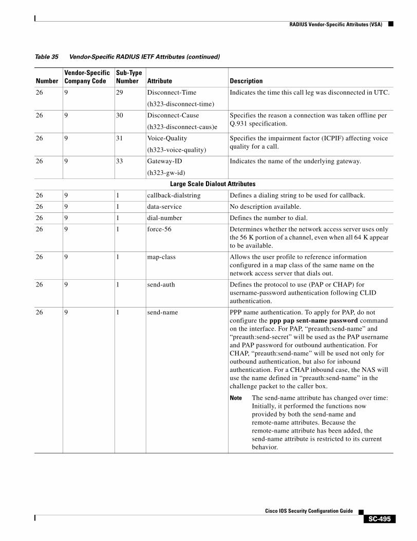
RADIUS Vendor-Specific Attributes (VSA)
SC-495Cisco IOS Security Configuration Guide
26 9 29 Disconnect-Time
(h323-disconnect-time)
Indicates the time this call leg was disconnected in UTC.
26 9 30 Disconnect-Cause
(h323-disconnect-caus)e
Specifies the reason a connection was taken offline per Q.931 specification.
26 9 31 Voice-Quality
(h323-voice-quality)
Specifies the impairment factor (ICPIF) affecting voice quality for a call.
26 9 33 Gateway-ID
(h323-gw-id)
Indicates the name of the underlying gateway.
Large Scale Dialout Attributes
26 9 1 callback-dialstring Defines a dialing string to be used for callback.
26 9 1 data-service No description available.
26 9 1 dial-number Defines the number to dial.
26 9 1 force-56 Determines whether the network access server uses only the 56 K portion of a channel, even when all 64 K appear to be available.
26 9 1 map-class Allows the user profile to reference information configured in a map class of the same name on the network access server that dials out.
26 9 1 send-auth Defines the protocol to use (PAP or CHAP) for username-password authentication following CLID authentication.
26 9 1 send-name PPP name authentication. To apply for PAP, do not configure the ppp pap sent-name password command on the interface. For PAP, “preauth:send-name” and “preauth:send-secret” will be used as the PAP username and PAP password for outbound authentication. For CHAP, “preauth:send-name” will be used not only for outbound authentication, but also for inbound authentication. For a CHAP inbound case, the NAS will use the name defined in “preauth:send-name” in the challenge packet to the caller box.
Note The send-name attribute has changed over time: Initially, it performed the functions now provided by both the send-name and remote-name attributes. Because the remote-name attribute has been added, the send-name attribute is restricted to its current behavior.
Table 35 Vendor-Specific RADIUS IETF Attributes (continued)
NumberVendor-SpecificCompany Code
Sub-TypeNumber Attribute Description
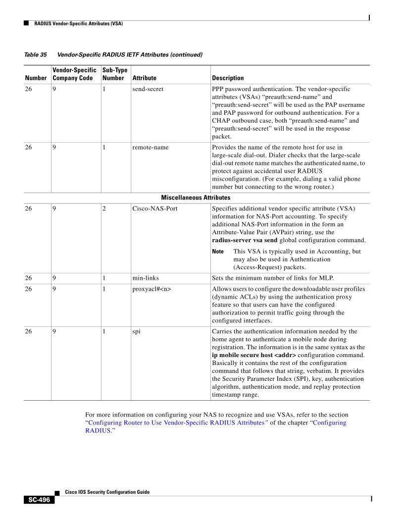
RADIUS Vendor-Specific Attributes (VSA)
SC-496Cisco IOS Security Configuration Guide
For more information on configuring your NAS to recognize and use VSAs, refer to the section “Configuring Router to Use Vendor-Specific RADIUS Attributes” of the chapter “Configuring RADIUS.”
26 9 1 send-secret PPP password authentication. The vendor-specific attributes (VSAs) “preauth:send-name” and “preauth:send-secret” will be used as the PAP username and PAP password for outbound authentication. For a CHAP outbound case, both “preauth:send-name” and “preauth:send-secret” will be used in the response packet.
26 9 1 remote-name Provides the name of the remote host for use in large-scale dial-out. Dialer checks that the large-scale dial-out remote name matches the authenticated name, to protect against accidental user RADIUS misconfiguration. (For example, dialing a valid phone number but connecting to the wrong router.)
Miscellaneous Attributes
26 9 2 Cisco-NAS-Port Specifies additional vendor specific attribute (VSA) information for NAS-Port accounting. To specify additional NAS-Port information in the form an Attribute-Value Pair (AVPair) string, use the radius-server vsa send global configuration command.
Note This VSA is typically used in Accounting, but may also be used in Authentication (Access-Request) packets.
26 9 1 min-links Sets the minimum number of links for MLP.
26 9 1 proxyacl#<n> Allows users to configure the downloadable user profiles (dynamic ACLs) by using the authentication proxy feature so that users can have the configured authorization to permit traffic going through the configured interfaces.
26 9 1 spi Carries the authentication information needed by the home agent to authenticate a mobile node during registration. The information is in the same syntax as the ip mobile secure host <addr> configuration command. Basically it contains the rest of the configuration command that follows that string, verbatim. It provides the Security Parameter Index (SPI), key, authentication algorithm, authentication mode, and replay protection timestamp range.
Table 35 Vendor-Specific RADIUS IETF Attributes (continued)
NumberVendor-SpecificCompany Code
Sub-TypeNumber Attribute Description
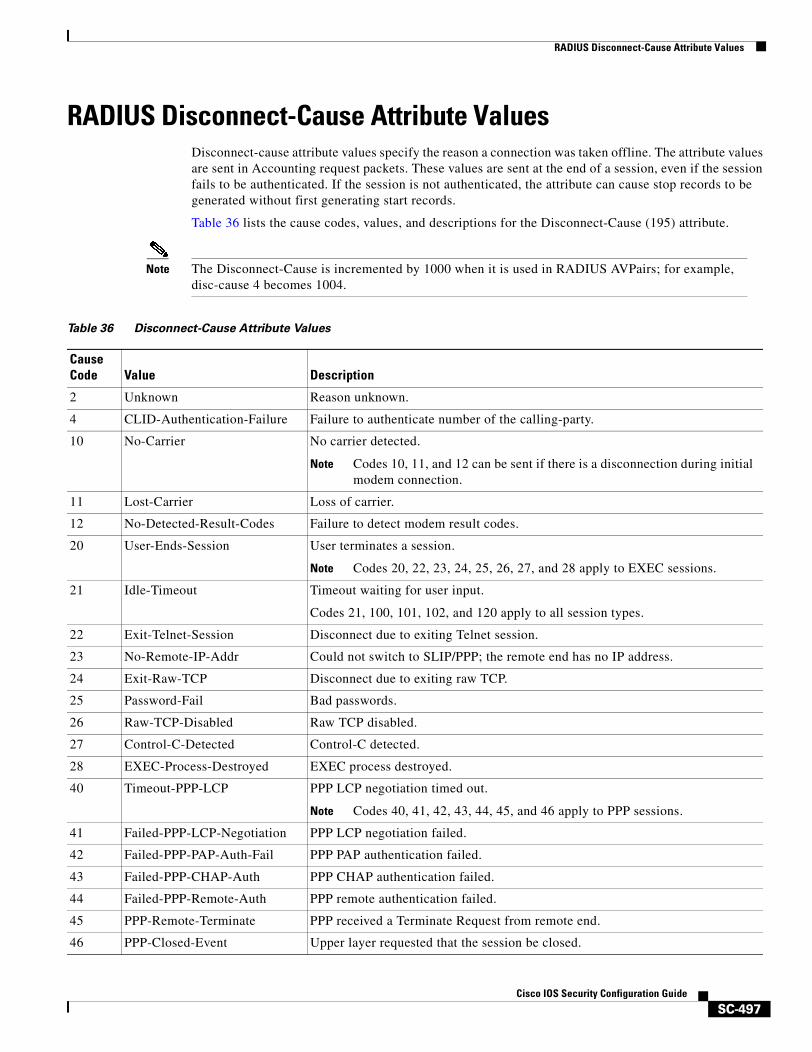
RADIUS Disconnect-Cause Attribute Values
SC-497Cisco IOS Security Configuration Guide
RADIUS Disconnect-Cause Attribute ValuesDisconnect-cause attribute values specify the reason a connection was taken offline. The attribute values are sent in Accounting request packets. These values are sent at the end of a session, even if the session fails to be authenticated. If the session is not authenticated, the attribute can cause stop records to be generated without first generating start records.
Table 36 lists the cause codes, values, and descriptions for the Disconnect-Cause (195) attribute.
Note The Disconnect-Cause is incremented by 1000 when it is used in RADIUS AVPairs; for example, disc-cause 4 becomes 1004.
Table 36 Disconnect-Cause Attribute Values
Cause Code Value Description
2 Unknown Reason unknown.
4 CLID-Authentication-Failure Failure to authenticate number of the calling-party.
10 No-Carrier No carrier detected.
Note Codes 10, 11, and 12 can be sent if there is a disconnection during initial modem connection.
11 Lost-Carrier Loss of carrier.
12 No-Detected-Result-Codes Failure to detect modem result codes.
20 User-Ends-Session User terminates a session.
Note Codes 20, 22, 23, 24, 25, 26, 27, and 28 apply to EXEC sessions.
21 Idle-Timeout Timeout waiting for user input.
Codes 21, 100, 101, 102, and 120 apply to all session types.
22 Exit-Telnet-Session Disconnect due to exiting Telnet session.
23 No-Remote-IP-Addr Could not switch to SLIP/PPP; the remote end has no IP address.
24 Exit-Raw-TCP Disconnect due to exiting raw TCP.
25 Password-Fail Bad passwords.
26 Raw-TCP-Disabled Raw TCP disabled.
27 Control-C-Detected Control-C detected.
28 EXEC-Process-Destroyed EXEC process destroyed.
40 Timeout-PPP-LCP PPP LCP negotiation timed out.
Note Codes 40, 41, 42, 43, 44, 45, and 46 apply to PPP sessions.
41 Failed-PPP-LCP-Negotiation PPP LCP negotiation failed.
42 Failed-PPP-PAP-Auth-Fail PPP PAP authentication failed.
43 Failed-PPP-CHAP-Auth PPP CHAP authentication failed.
44 Failed-PPP-Remote-Auth PPP remote authentication failed.
45 PPP-Remote-Terminate PPP received a Terminate Request from remote end.
46 PPP-Closed-Event Upper layer requested that the session be closed.

RADIUS Disconnect-Cause Attribute Values
SC-498Cisco IOS Security Configuration Guide
63 PPP-Echo-Replies TCP connection has been closed.
100 Session-Timeout Session timed out.
101 Session-Failed-Security Session failed for security reasons.
102 Session-End-Callback Session terminated due to callback.
120 Invalid-Protocol Call refused because the detected protocol is disabled.
600 VPN-User-Disconnect Call disconnected by client (through PPP).
Code is sent if the LNS receives a PPP terminate request from the client.
601 VPN-Carrier-Loss Loss of carrier. This can be the result of a physical line going dead.
Code is sent when a client is unable to dial out using a dialer.
602 VPN-No-Resources No resources available to handle the call.
Code is sent when the client is unable to allocate memory (running low on memory).
603 VPN-Bad-Control-Packet Bad L2TP or L2F control packets.
This code is sent when an invalid control packet, such as missing mandatory Attribute-Value pairs (AVP), from the peer is received. When using L2TP, the code will be sent after six retransmits; when using L2F, the number of retransmits is user configurable.
Note VPN-Tunnel-Shut will be sent if there are active sessions in the tunnel.
604 VPN-Admin-Disconnect Administrative disconnect. This can be the result of a VPN soft shutdown, which is when a client reaches maximum session limit or exceeds maximum hopcount.
Code is sent when a tunnel is brought down by issuing the clear vpdn tunnel command.
605 VPN-Tunnel-Shut Tunnel teardown or tunnel setup has failed.
Code is sent when there are active sessions in a tunnel and the tunnel goes down.
Note This code is not sent when tunnel authentication fails.
606 VPN-Local-Disconnect Call is disconnected by LNS PPP module.
Code is sent when the LNS sends a PPP terminate request to the client. It indicates a normal PPP disconnection initiated by the LNS.
607 VPN-Session-Limit VPN soft shutdown is enabled.
Code is sent when a call has been refused due to any of the soft shutdown restrictions previously mentioned.
Table 36 Disconnect-Cause Attribute Values (continued)
Cause Code Value Description
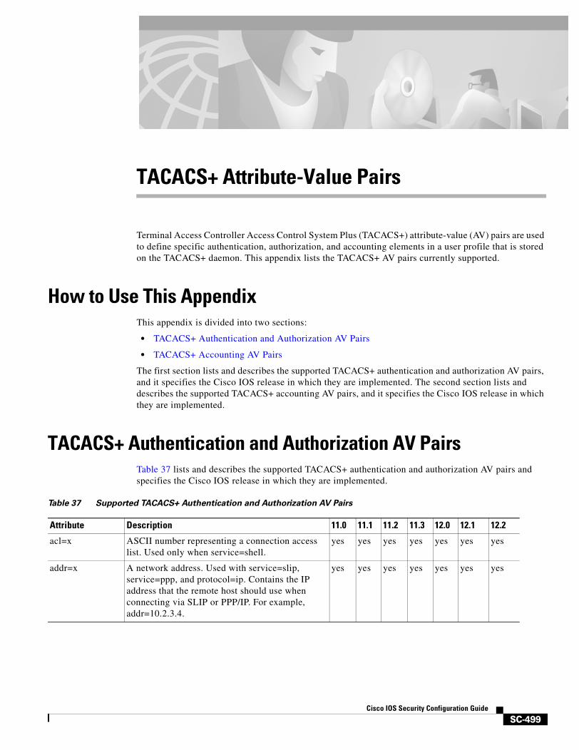
SC-499Cisco IOS Security Configuration Guide
TACACS+ Attribute-Value Pairs
Terminal Access Controller Access Control System Plus (TACACS+) attribute-value (AV) pairs are used to define specific authentication, authorization, and accounting elements in a user profile that is stored on the TACACS+ daemon. This appendix lists the TACACS+ AV pairs currently supported.
How to Use This AppendixThis appendix is divided into two sections:
• TACACS+ Authentication and Authorization AV Pairs
• TACACS+ Accounting AV Pairs
The first section lists and describes the supported TACACS+ authentication and authorization AV pairs, and it specifies the Cisco IOS release in which they are implemented. The second section lists and describes the supported TACACS+ accounting AV pairs, and it specifies the Cisco IOS release in which they are implemented.
TACACS+ Authentication and Authorization AV PairsTable 37 lists and describes the supported TACACS+ authentication and authorization AV pairs and specifies the Cisco IOS release in which they are implemented.
Table 37 Supported TACACS+ Authentication and Authorization AV Pairs
Attribute Description 11.0 11.1 11.2 11.3 12.0 12.1 12.2
acl=x ASCII number representing a connection access list. Used only when service=shell.
yes yes yes yes yes yes yes
addr=x A network address. Used with service=slip, service=ppp, and protocol=ip. Contains the IP address that the remote host should use when connecting via SLIP or PPP/IP. For example, addr=10.2.3.4.
yes yes yes yes yes yes yes
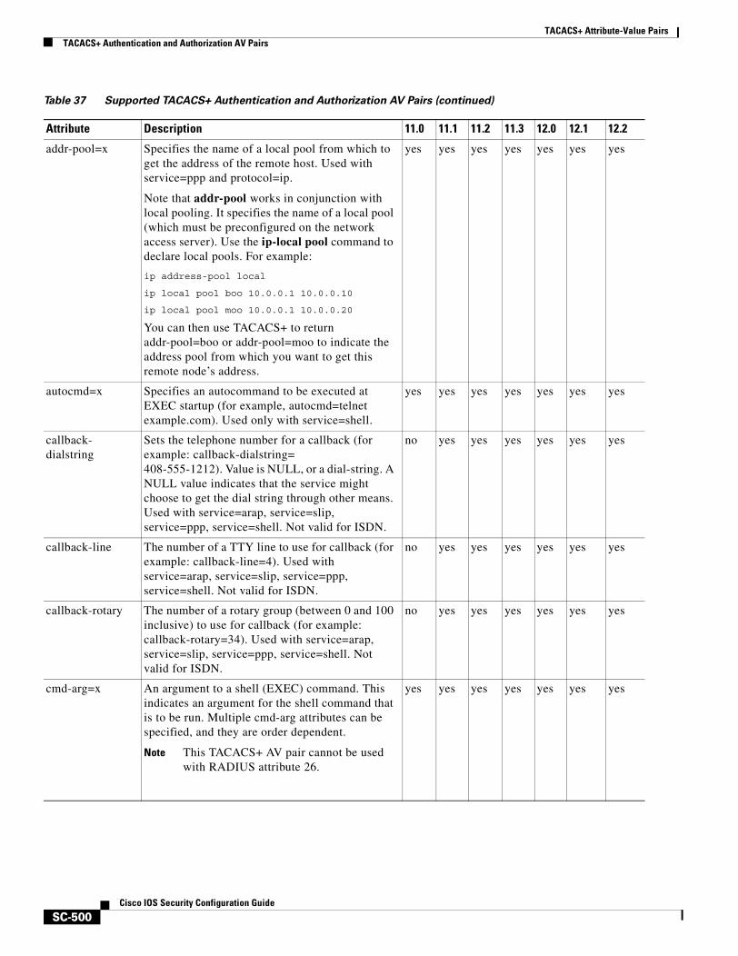
TACACS+ Attribute-Value PairsTACACS+ Authentication and Authorization AV Pairs
SC-500Cisco IOS Security Configuration Guide
addr-pool=x Specifies the name of a local pool from which to get the address of the remote host. Used with service=ppp and protocol=ip.
Note that addr-pool works in conjunction with local pooling. It specifies the name of a local pool (which must be preconfigured on the network access server). Use the ip-local pool command to declare local pools. For example:
ip address-pool local
ip local pool boo 10.0.0.1 10.0.0.10
ip local pool moo 10.0.0.1 10.0.0.20
You can then use TACACS+ to return addr-pool=boo or addr-pool=moo to indicate the address pool from which you want to get this remote node’s address.
yes yes yes yes yes yes yes
autocmd=x Specifies an autocommand to be executed at EXEC startup (for example, autocmd=telnet example.com). Used only with service=shell.
yes yes yes yes yes yes yes
callback-dialstring
Sets the telephone number for a callback (for example: callback-dialstring=408-555-1212). Value is NULL, or a dial-string. A NULL value indicates that the service might choose to get the dial string through other means. Used with service=arap, service=slip, service=ppp, service=shell. Not valid for ISDN.
no yes yes yes yes yes yes
callback-line The number of a TTY line to use for callback (for example: callback-line=4). Used with service=arap, service=slip, service=ppp, service=shell. Not valid for ISDN.
no yes yes yes yes yes yes
callback-rotary The number of a rotary group (between 0 and 100 inclusive) to use for callback (for example: callback-rotary=34). Used with service=arap, service=slip, service=ppp, service=shell. Not valid for ISDN.
no yes yes yes yes yes yes
cmd-arg=x An argument to a shell (EXEC) command. This indicates an argument for the shell command that is to be run. Multiple cmd-arg attributes can be specified, and they are order dependent.
Note This TACACS+ AV pair cannot be used with RADIUS attribute 26.
yes yes yes yes yes yes yes
Table 37 Supported TACACS+ Authentication and Authorization AV Pairs (continued)
Attribute Description 11.0 11.1 11.2 11.3 12.0 12.1 12.2

TACACS+ Attribute-Value PairsTACACS+ Authentication and Authorization AV Pairs
SC-501Cisco IOS Security Configuration Guide
cmd=x A shell (EXEC) command. This indicates the command name for a shell command that is to be run. This attribute must be specified if service equals “shell.” A NULL value indicates that the shell itself is being referred to.
Note This TACACS+ AV pair cannot be used with RADIUS attribute 26.
yes yes yes yes yes yes yes
data-service Used with the service=outbound and protocol=ip. no no no no no yes yes
dial-number Defines the number to dial. Used with the service=outbound and protocol=ip.
no no no no no yes yes
dns-servers= Identifies a DNS server (primary or secondary) that can be requested by Microsoft PPP clients from the network access server during IPCP negotiation. To be used with service=ppp and protocol=ip. The IP address identifying each DNS server is entered in dotted decimal format.
no no no yes yes yes yes
force-56 Determines whether the network access server uses only the 56 K portion of a channel, even when all 64 K appear to be available. To turn on this attribute, use the “true” value (force-56=true). Any other value is treated as false. Used with the service=outbound and protocol=ip.
no no no no no yes yes
gw-password Specifies the password for the home gateway during the L2F tunnel authentication. Used with service=ppp and protocol=vpdn.
no no yes yes yes yes yes
idletime=x Sets a value, in minutes, after which an idle session is terminated. A value of zero indicates no timeout.
no yes yes yes yes yes yes
inacl#<n> ASCII access list identifier for an input access list to be installed and applied to an interface for the duration of the current connection. Used with service=ppp and protocol=ip, and service service=ppp and protocol =ipx. Per-user access lists do not currently work with ISDN interfaces.
no no no yes yes yes yes
inacl=x ASCII identifier for an interface input access list. Used with service=ppp and protocol=ip. Per-user access lists do not currently work with ISDN interfaces.
yes yes yes yes yes yes yes
Table 37 Supported TACACS+ Authentication and Authorization AV Pairs (continued)
Attribute Description 11.0 11.1 11.2 11.3 12.0 12.1 12.2
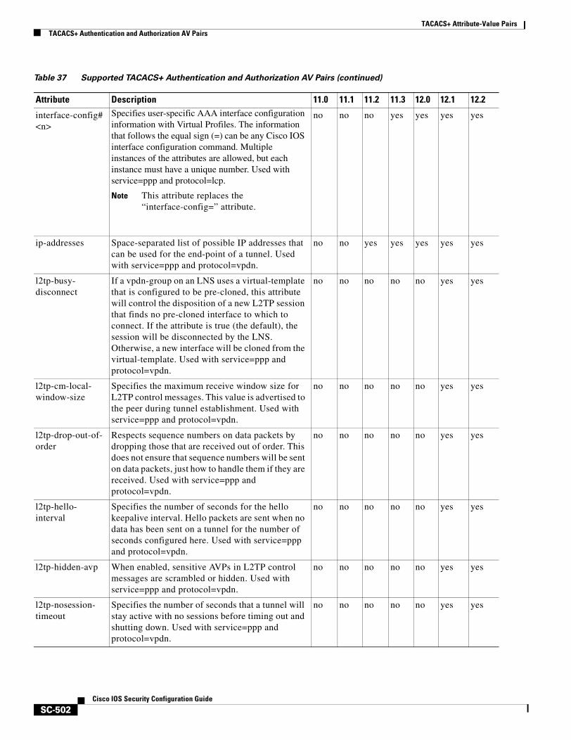
TACACS+ Attribute-Value PairsTACACS+ Authentication and Authorization AV Pairs
SC-502Cisco IOS Security Configuration Guide
interface-config#<n>
Specifies user-specific AAA interface configuration information with Virtual Profiles. The information that follows the equal sign (=) can be any Cisco IOS interface configuration command. Multiple instances of the attributes are allowed, but each instance must have a unique number. Used with service=ppp and protocol=lcp.
Note This attribute replaces the “interface-config=” attribute.
no no no yes yes yes yes
ip-addresses Space-separated list of possible IP addresses that can be used for the end-point of a tunnel. Used with service=ppp and protocol=vpdn.
no no yes yes yes yes yes
l2tp-busy-disconnect
If a vpdn-group on an LNS uses a virtual-template that is configured to be pre-cloned, this attribute will control the disposition of a new L2TP session that finds no pre-cloned interface to which to connect. If the attribute is true (the default), the session will be disconnected by the LNS. Otherwise, a new interface will be cloned from the virtual-template. Used with service=ppp and protocol=vpdn.
no no no no no yes yes
l2tp-cm-local-window-size
Specifies the maximum receive window size for L2TP control messages. This value is advertised to the peer during tunnel establishment. Used with service=ppp and protocol=vpdn.
no no no no no yes yes
l2tp-drop-out-of-order
Respects sequence numbers on data packets by dropping those that are received out of order. This does not ensure that sequence numbers will be sent on data packets, just how to handle them if they are received. Used with service=ppp and protocol=vpdn.
no no no no no yes yes
l2tp-hello-interval
Specifies the number of seconds for the hello keepalive interval. Hello packets are sent when no data has been sent on a tunnel for the number of seconds configured here. Used with service=ppp and protocol=vpdn.
no no no no no yes yes
l2tp-hidden-avp When enabled, sensitive AVPs in L2TP control messages are scrambled or hidden. Used with service=ppp and protocol=vpdn.
no no no no no yes yes
l2tp-nosession-timeout
Specifies the number of seconds that a tunnel will stay active with no sessions before timing out and shutting down. Used with service=ppp and protocol=vpdn.
no no no no no yes yes
Table 37 Supported TACACS+ Authentication and Authorization AV Pairs (continued)
Attribute Description 11.0 11.1 11.2 11.3 12.0 12.1 12.2
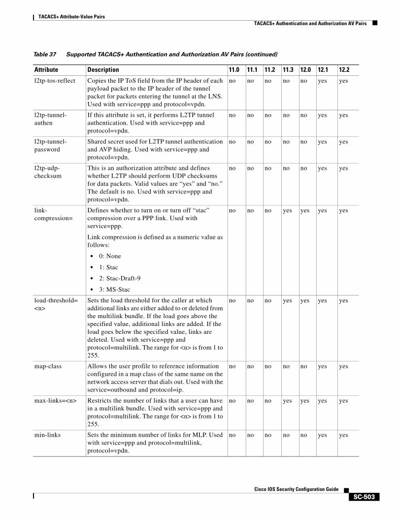
TACACS+ Attribute-Value PairsTACACS+ Authentication and Authorization AV Pairs
SC-503Cisco IOS Security Configuration Guide
l2tp-tos-reflect Copies the IP ToS field from the IP header of each payload packet to the IP header of the tunnel packet for packets entering the tunnel at the LNS. Used with service=ppp and protocol=vpdn.
no no no no no yes yes
l2tp-tunnel-authen
If this attribute is set, it performs L2TP tunnel authentication. Used with service=ppp and protocol=vpdn.
no no no no no yes yes
l2tp-tunnel-password
Shared secret used for L2TP tunnel authentication and AVP hiding. Used with service=ppp and protocol=vpdn.
no no no no no yes yes
l2tp-udp-checksum
This is an authorization attribute and defines whether L2TP should perform UDP checksums for data packets. Valid values are “yes” and “no.” The default is no. Used with service=ppp and protocol=vpdn.
no no no no no yes yes
link-compression=
Defines whether to turn on or turn off “stac” compression over a PPP link. Used with service=ppp.
Link compression is defined as a numeric value as follows:
• 0: None
• 1: Stac
• 2: Stac-Draft-9
• 3: MS-Stac
no no no yes yes yes yes
load-threshold=<n>
Sets the load threshold for the caller at which additional links are either added to or deleted from the multilink bundle. If the load goes above the specified value, additional links are added. If the load goes below the specified value, links are deleted. Used with service=ppp and protocol=multilink. The range for <n> is from 1 to 255.
no no no yes yes yes yes
map-class Allows the user profile to reference information configured in a map class of the same name on the network access server that dials out. Used with the service=outbound and protocol=ip.
no no no no no yes yes
max-links=<n> Restricts the number of links that a user can have in a multilink bundle. Used with service=ppp and protocol=multilink. The range for <n> is from 1 to 255.
no no no yes yes yes yes
min-links Sets the minimum number of links for MLP. Used with service=ppp and protocol=multilink, protocol=vpdn.
no no no no no yes yes
Table 37 Supported TACACS+ Authentication and Authorization AV Pairs (continued)
Attribute Description 11.0 11.1 11.2 11.3 12.0 12.1 12.2
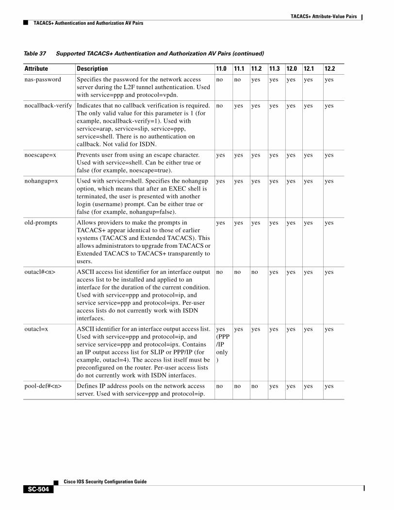
TACACS+ Attribute-Value PairsTACACS+ Authentication and Authorization AV Pairs
SC-504Cisco IOS Security Configuration Guide
nas-password Specifies the password for the network access server during the L2F tunnel authentication. Used with service=ppp and protocol=vpdn.
no no yes yes yes yes yes
nocallback-verify Indicates that no callback verification is required. The only valid value for this parameter is 1 (for example, nocallback-verify=1). Used with service=arap, service=slip, service=ppp, service=shell. There is no authentication on callback. Not valid for ISDN.
no yes yes yes yes yes yes
noescape=x Prevents user from using an escape character. Used with service=shell. Can be either true or false (for example, noescape=true).
yes yes yes yes yes yes yes
nohangup=x Used with service=shell. Specifies the nohangup option, which means that after an EXEC shell is terminated, the user is presented with another login (username) prompt. Can be either true or false (for example, nohangup=false).
yes yes yes yes yes yes yes
old-prompts Allows providers to make the prompts in TACACS+ appear identical to those of earlier systems (TACACS and Extended TACACS). This allows administrators to upgrade from TACACS or Extended TACACS to TACACS+ transparently to users.
yes yes yes yes yes yes yes
outacl#<n> ASCII access list identifier for an interface output access list to be installed and applied to an interface for the duration of the current condition. Used with service=ppp and protocol=ip, and service service=ppp and protocol=ipx. Per-user access lists do not currently work with ISDN interfaces.
no no no yes yes yes yes
outacl=x ASCII identifier for an interface output access list. Used with service=ppp and protocol=ip, and service service=ppp and protocol=ipx. Contains an IP output access list for SLIP or PPP/IP (for example, outacl=4). The access list itself must be preconfigured on the router. Per-user access lists do not currently work with ISDN interfaces.
yes(PPP/IPonly)
yes yes yes yes yes yes
pool-def#<n> Defines IP address pools on the network access server. Used with service=ppp and protocol=ip.
no no no yes yes yes yes
Table 37 Supported TACACS+ Authentication and Authorization AV Pairs (continued)
Attribute Description 11.0 11.1 11.2 11.3 12.0 12.1 12.2
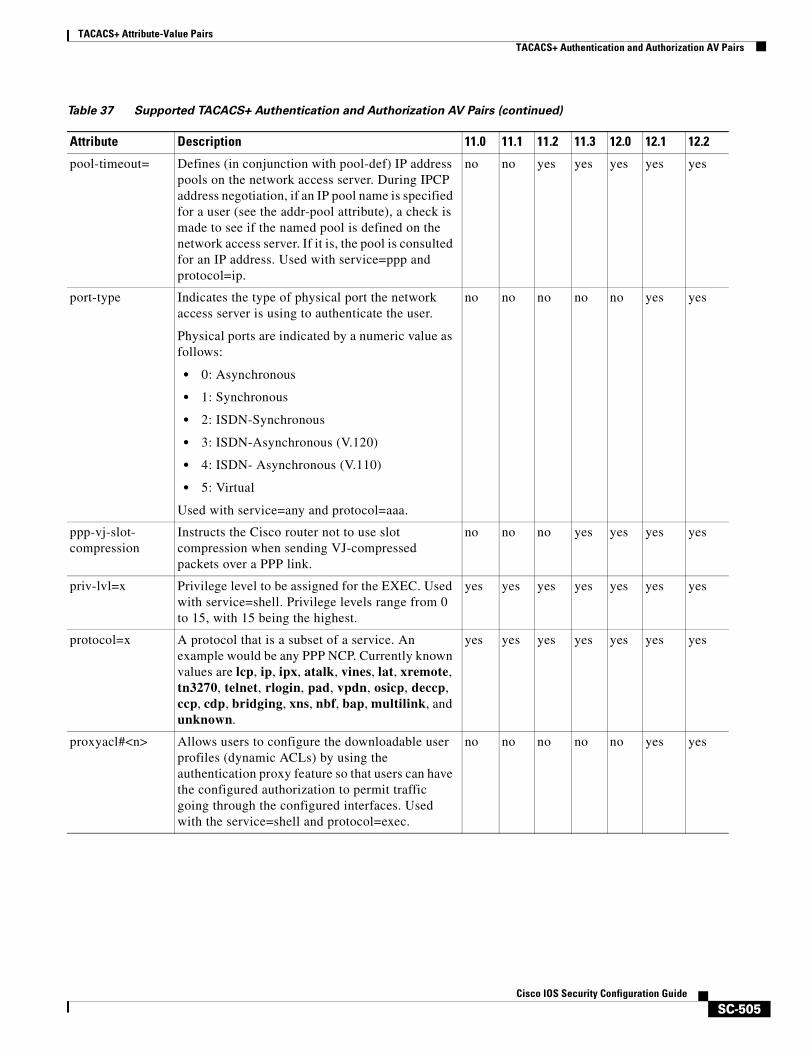
TACACS+ Attribute-Value PairsTACACS+ Authentication and Authorization AV Pairs
SC-505Cisco IOS Security Configuration Guide
pool-timeout= Defines (in conjunction with pool-def) IP address pools on the network access server. During IPCP address negotiation, if an IP pool name is specified for a user (see the addr-pool attribute), a check is made to see if the named pool is defined on the network access server. If it is, the pool is consulted for an IP address. Used with service=ppp and protocol=ip.
no no yes yes yes yes yes
port-type Indicates the type of physical port the network access server is using to authenticate the user.
Physical ports are indicated by a numeric value as follows:
• 0: Asynchronous
• 1: Synchronous
• 2: ISDN-Synchronous
• 3: ISDN-Asynchronous (V.120)
• 4: ISDN- Asynchronous (V.110)
• 5: Virtual
Used with service=any and protocol=aaa.
no no no no no yes yes
ppp-vj-slot-compression
Instructs the Cisco router not to use slot compression when sending VJ-compressed packets over a PPP link.
no no no yes yes yes yes
priv-lvl=x Privilege level to be assigned for the EXEC. Used with service=shell. Privilege levels range from 0 to 15, with 15 being the highest.
yes yes yes yes yes yes yes
protocol=x A protocol that is a subset of a service. An example would be any PPP NCP. Currently known values are lcp, ip, ipx, atalk, vines, lat, xremote, tn3270, telnet, rlogin, pad, vpdn, osicp, deccp, ccp, cdp, bridging, xns, nbf, bap, multilink, and unknown.
yes yes yes yes yes yes yes
proxyacl#<n> Allows users to configure the downloadable user profiles (dynamic ACLs) by using the authentication proxy feature so that users can have the configured authorization to permit traffic going through the configured interfaces. Used with the service=shell and protocol=exec.
no no no no no yes yes
Table 37 Supported TACACS+ Authentication and Authorization AV Pairs (continued)
Attribute Description 11.0 11.1 11.2 11.3 12.0 12.1 12.2
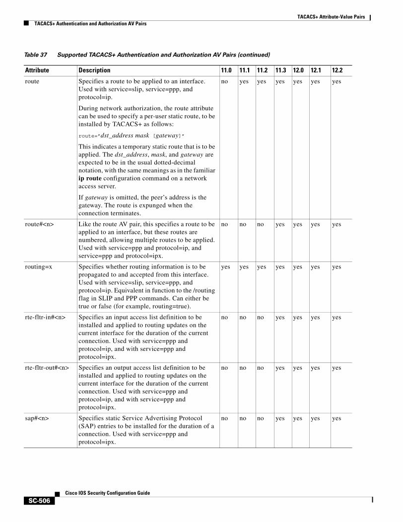
TACACS+ Attribute-Value PairsTACACS+ Authentication and Authorization AV Pairs
SC-506Cisco IOS Security Configuration Guide
route Specifies a route to be applied to an interface. Used with service=slip, service=ppp, and protocol=ip.
During network authorization, the route attribute can be used to specify a per-user static route, to be installed by TACACS+ as follows:
route=”dst_address mask [gateway]”
This indicates a temporary static route that is to be applied. The dst_address, mask, and gateway are expected to be in the usual dotted-decimal notation, with the same meanings as in the familiar ip route configuration command on a network access server.
If gateway is omitted, the peer’s address is the gateway. The route is expunged when the connection terminates.
no yes yes yes yes yes yes
route#<n> Like the route AV pair, this specifies a route to be applied to an interface, but these routes are numbered, allowing multiple routes to be applied. Used with service=ppp and protocol=ip, and service=ppp and protocol=ipx.
no no no yes yes yes yes
routing=x Specifies whether routing information is to be propagated to and accepted from this interface. Used with service=slip, service=ppp, and protocol=ip. Equivalent in function to the /routing flag in SLIP and PPP commands. Can either be true or false (for example, routing=true).
yes yes yes yes yes yes yes
rte-fltr-in#<n> Specifies an input access list definition to be installed and applied to routing updates on the current interface for the duration of the current connection. Used with service=ppp and protocol=ip, and with service=ppp and protocol=ipx.
no no no yes yes yes yes
rte-fltr-out#<n> Specifies an output access list definition to be installed and applied to routing updates on the current interface for the duration of the current connection. Used with service=ppp and protocol=ip, and with service=ppp and protocol=ipx.
no no no yes yes yes yes
sap#<n> Specifies static Service Advertising Protocol (SAP) entries to be installed for the duration of a connection. Used with service=ppp and protocol=ipx.
no no no yes yes yes yes
Table 37 Supported TACACS+ Authentication and Authorization AV Pairs (continued)
Attribute Description 11.0 11.1 11.2 11.3 12.0 12.1 12.2

TACACS+ Attribute-Value PairsTACACS+ Authentication and Authorization AV Pairs
SC-507Cisco IOS Security Configuration Guide
sap-fltr-in#<n> Specifies an input SAP filter access list definition to be installed and applied on the current interface for the duration of the current connection. Used with service=ppp and protocol=ipx.
no no no yes yes yes yes
sap-fltr-out#<n> Specifies an output SAP filter access list definition to be installed and applied on the current interface for the duration of the current connection. Used with service=ppp and protocol=ipx.
no no no yes yes yes yes
send-auth Defines the protocol to use (PAP or CHAP) for username-password authentication following CLID authentication. Used with service=any and protocol=aaa.
no no no no no yes yes
send-secret Specifies the password that the NAS needs to respond to a chap/pap request from the remote end of a connection on an outgoing call. Used with service=ppp and protocol=ip.
no no no no no yes yes
service=x The primary service. Specifying a service attribute indicates that this is a request for authorization or accounting of that service. Current values are slip, ppp, arap, shell, tty-daemon, connection, and system. This attribute must always be included.
yes yes yes yes yes yes yes
source-ip=x Used as the source IP address of all VPDN packets generated as part of a VPDN tunnel. This is equivalent to the Cisco vpdn outgoing global configuration command.
no no yes yes yes yes yes
spi Carries the authentication information needed by the home agent to authenticate a mobile node during registration. The information is in the same syntax as the ip mobile secure host <addr> configuration command. Basically it contains the rest of the configuration command that follows that string, verbatim. It provides the Security Parameter Index (SPI), key, authentication algorithm, authentication mode, and replay protection timestamp range. Used with the service=mobileip and protocol=ip.
no no no no no yes yes
timeout=x The number of minutes before an EXEC or ARA session disconnects (for example, timeout=60). A value of zero indicates no timeout. Used with service=arap.
yes yes yes yes yes yes yes
tunnel-id Specifies the username that will be used to authenticate the tunnel over which the individual user MID will be projected. This is analogous to the remote name in the vpdn outgoing command. Used with service=ppp and protocol=vpdn.
no no yes yes yes yes yes
Table 37 Supported TACACS+ Authentication and Authorization AV Pairs (continued)
Attribute Description 11.0 11.1 11.2 11.3 12.0 12.1 12.2
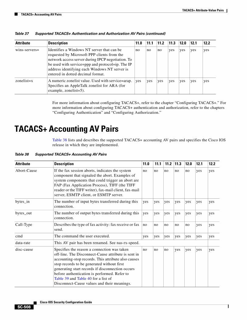
TACACS+ Attribute-Value PairsTACACS+ Accounting AV Pairs
SC-508Cisco IOS Security Configuration Guide
For more information about configuring TACACS+, refer to the chapter “Configuring TACACS+.” For more information about configuring TACACS+ authentication and authorization, refer to the chapters “Configuring Authentication” and “Configuring Authorization.”
TACACS+ Accounting AV PairsTable 38 lists and describes the supported TACACS+ accounting AV pairs and specifies the Cisco IOS release in which they are implemented.
wins-servers= Identifies a Windows NT server that can be requested by Microsoft PPP clients from the network access server during IPCP negotiation. To be used with service=ppp and protocol=ip. The IP address identifying each Windows NT server is entered in dotted decimal format.
no no no yes yes yes yes
zonelist=x A numeric zonelist value. Used with service=arap. Specifies an AppleTalk zonelist for ARA (for example, zonelist=5).
yes yes yes yes yes yes yes
Table 37 Supported TACACS+ Authentication and Authorization AV Pairs (continued)
Attribute Description 11.0 11.1 11.2 11.3 12.0 12.1 12.2
Table 38 Supported TACACS+ Accounting AV Pairs
Attribute Description 11.0 11.1 11.2 11.3 12.0 12.1 12.2
Abort-Cause If the fax session aborts, indicates the system component that signaled the abort. Examples of system components that could trigger an abort are FAP (Fax Application Process), TIFF (the TIFF reader or the TIFF writer), fax-mail client, fax-mail server, ESMTP client, or ESMTP server.
no no no no no yes yes
bytes_in The number of input bytes transferred during this connection.
yes yes yes yes yes yes yes
bytes_out The number of output bytes transferred during this connection.
yes yes yes yes yes yes yes
Call-Type Describes the type of fax activity: fax receive or fax send.
no no no no no yes yes
cmd The command the user executed. yes yes yes yes yes yes yes
data-rate This AV pair has been renamed. See nas-rx-speed.
disc-cause Specifies the reason a connection was taken off-line. The Disconnect-Cause attribute is sent in accounting-stop records. This attribute also causes stop records to be generated without first generating start records if disconnection occurs before authentication is performed. Refer to Table 39 and Table 40 for a list of Disconnect-Cause values and their meanings.
no no no yes yes yes yes
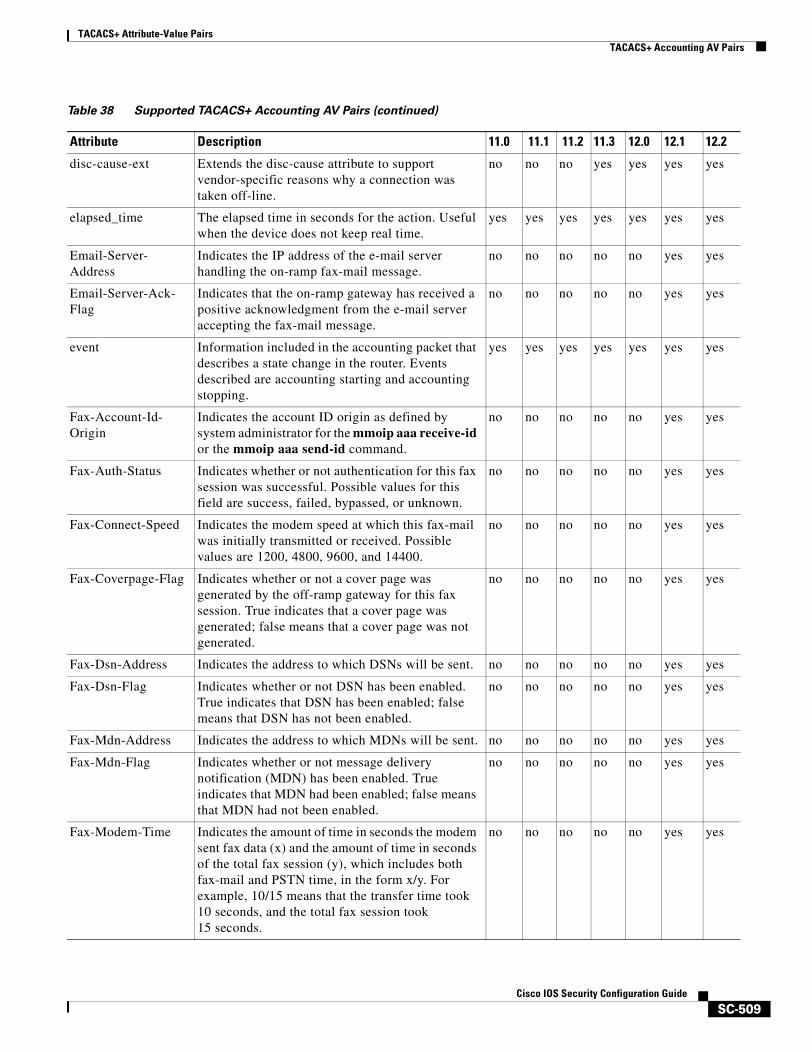
TACACS+ Attribute-Value PairsTACACS+ Accounting AV Pairs
SC-509Cisco IOS Security Configuration Guide
disc-cause-ext Extends the disc-cause attribute to support vendor-specific reasons why a connection was taken off-line.
no no no yes yes yes yes
elapsed_time The elapsed time in seconds for the action. Useful when the device does not keep real time.
yes yes yes yes yes yes yes
Email-Server-Address
Indicates the IP address of the e-mail server handling the on-ramp fax-mail message.
no no no no no yes yes
Email-Server-Ack-Flag
Indicates that the on-ramp gateway has received a positive acknowledgment from the e-mail server accepting the fax-mail message.
no no no no no yes yes
event Information included in the accounting packet that describes a state change in the router. Events described are accounting starting and accounting stopping.
yes yes yes yes yes yes yes
Fax-Account-Id-Origin
Indicates the account ID origin as defined by system administrator for the mmoip aaa receive-id or the mmoip aaa send-id command.
no no no no no yes yes
Fax-Auth-Status Indicates whether or not authentication for this fax session was successful. Possible values for this field are success, failed, bypassed, or unknown.
no no no no no yes yes
Fax-Connect-Speed Indicates the modem speed at which this fax-mail was initially transmitted or received. Possible values are 1200, 4800, 9600, and 14400.
no no no no no yes yes
Fax-Coverpage-Flag Indicates whether or not a cover page was generated by the off-ramp gateway for this fax session. True indicates that a cover page was generated; false means that a cover page was not generated.
no no no no no yes yes
Fax-Dsn-Address Indicates the address to which DSNs will be sent. no no no no no yes yes
Fax-Dsn-Flag Indicates whether or not DSN has been enabled. True indicates that DSN has been enabled; false means that DSN has not been enabled.
no no no no no yes yes
Fax-Mdn-Address Indicates the address to which MDNs will be sent. no no no no no yes yes
Fax-Mdn-Flag Indicates whether or not message delivery notification (MDN) has been enabled. True indicates that MDN had been enabled; false means that MDN had not been enabled.
no no no no no yes yes
Fax-Modem-Time Indicates the amount of time in seconds the modem sent fax data (x) and the amount of time in seconds of the total fax session (y), which includes both fax-mail and PSTN time, in the form x/y. For example, 10/15 means that the transfer time took 10 seconds, and the total fax session took 15 seconds.
no no no no no yes yes
Table 38 Supported TACACS+ Accounting AV Pairs (continued)
Attribute Description 11.0 11.1 11.2 11.3 12.0 12.1 12.2
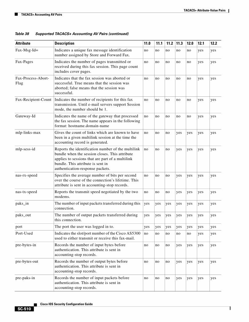
TACACS+ Attribute-Value PairsTACACS+ Accounting AV Pairs
SC-510Cisco IOS Security Configuration Guide
Fax-Msg-Id= Indicates a unique fax message identification number assigned by Store and Forward Fax.
no no no no no yes yes
Fax-Pages Indicates the number of pages transmitted or received during this fax session. This page count includes cover pages.
no no no no no yes yes
Fax-Process-Abort-Flag
Indicates that the fax session was aborted or successful. True means that the session was aborted; false means that the session was successful.
no no no no no yes yes
Fax-Recipient-Count Indicates the number of recipients for this fax transmission. Until e-mail servers support Session mode, the number should be 1.
no no no no no yes yes
Gateway-Id Indicates the name of the gateway that processed the fax session. The name appears in the following format: hostname.domain-name
no no no no no yes yes
mlp-links-max Gives the count of links which are known to have been in a given multilink session at the time the accounting record is generated.
no no no yes yes yes yes
mlp-sess-id Reports the identification number of the multilink bundle when the session closes. This attribute applies to sessions that are part of a multilink bundle. This attribute is sent in authentication-response packets.
no no no yes yes yes yes
nas-rx-speed Specifies the average number of bits per second over the course of the connection’s lifetime. This attribute is sent in accounting-stop records.
no no no yes yes yes yes
nas-tx-speed Reports the transmit speed negotiated by the two modems.
no no no yes yes yes yes
paks_in The number of input packets transferred during this connection.
yes yes yes yes yes yes yes
paks_out The number of output packets transferred during this connection.
yes yes yes yes yes yes yes
port The port the user was logged in to. yes yes yes yes yes yes yes
Port-Used Indicates the slot/port number of the Cisco AS5300 used to either transmit or receive this fax-mail.
no no no no no yes yes
pre-bytes-in Records the number of input bytes before authentication. This attribute is sent in accounting-stop records.
no no no yes yes yes yes
pre-bytes-out Records the number of output bytes before authentication. This attribute is sent in accounting-stop records.
no no no yes yes yes yes
pre-paks-in Records the number of input packets before authentication. This attribute is sent in accounting-stop records.
no no no yes yes yes yes
Table 38 Supported TACACS+ Accounting AV Pairs (continued)
Attribute Description 11.0 11.1 11.2 11.3 12.0 12.1 12.2
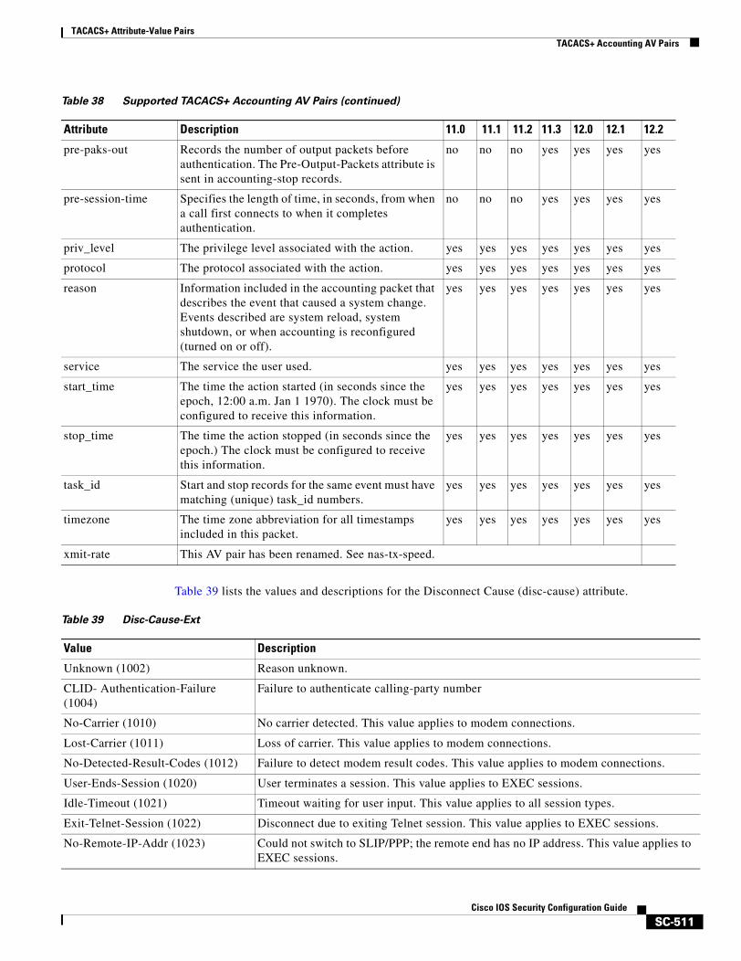
TACACS+ Attribute-Value PairsTACACS+ Accounting AV Pairs
SC-511Cisco IOS Security Configuration Guide
Table 39 lists the values and descriptions for the Disconnect Cause (disc-cause) attribute.
pre-paks-out Records the number of output packets before authentication. The Pre-Output-Packets attribute is sent in accounting-stop records.
no no no yes yes yes yes
pre-session-time Specifies the length of time, in seconds, from when a call first connects to when it completes authentication.
no no no yes yes yes yes
priv_level The privilege level associated with the action. yes yes yes yes yes yes yes
protocol The protocol associated with the action. yes yes yes yes yes yes yes
reason Information included in the accounting packet that describes the event that caused a system change. Events described are system reload, system shutdown, or when accounting is reconfigured (turned on or off).
yes yes yes yes yes yes yes
service The service the user used. yes yes yes yes yes yes yes
start_time The time the action started (in seconds since the epoch, 12:00 a.m. Jan 1 1970). The clock must be configured to receive this information.
yes yes yes yes yes yes yes
stop_time The time the action stopped (in seconds since the epoch.) The clock must be configured to receive this information.
yes yes yes yes yes yes yes
task_id Start and stop records for the same event must have matching (unique) task_id numbers.
yes yes yes yes yes yes yes
timezone The time zone abbreviation for all timestamps included in this packet.
yes yes yes yes yes yes yes
xmit-rate This AV pair has been renamed. See nas-tx-speed.
Table 38 Supported TACACS+ Accounting AV Pairs (continued)
Attribute Description 11.0 11.1 11.2 11.3 12.0 12.1 12.2
Table 39 Disc-Cause-Ext
Value Description
Unknown (1002) Reason unknown.
CLID- Authentication-Failure (1004)
Failure to authenticate calling-party number
No-Carrier (1010) No carrier detected. This value applies to modem connections.
Lost-Carrier (1011) Loss of carrier. This value applies to modem connections.
No-Detected-Result-Codes (1012) Failure to detect modem result codes. This value applies to modem connections.
User-Ends-Session (1020) User terminates a session. This value applies to EXEC sessions.
Idle-Timeout (1021) Timeout waiting for user input. This value applies to all session types.
Exit-Telnet-Session (1022) Disconnect due to exiting Telnet session. This value applies to EXEC sessions.
No-Remote-IP-Addr (1023) Could not switch to SLIP/PPP; the remote end has no IP address. This value applies to EXEC sessions.
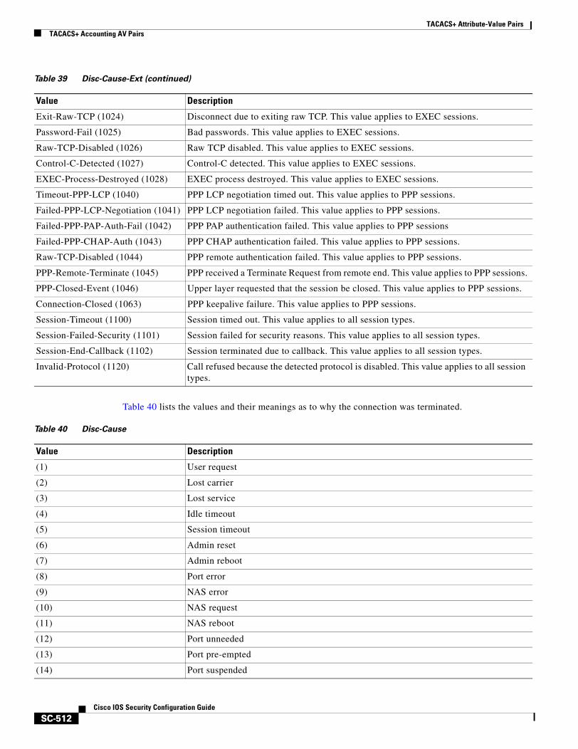
TACACS+ Attribute-Value PairsTACACS+ Accounting AV Pairs
SC-512Cisco IOS Security Configuration Guide
Table 40 lists the values and their meanings as to why the connection was terminated.
Exit-Raw-TCP (1024) Disconnect due to exiting raw TCP. This value applies to EXEC sessions.
Password-Fail (1025) Bad passwords. This value applies to EXEC sessions.
Raw-TCP-Disabled (1026) Raw TCP disabled. This value applies to EXEC sessions.
Control-C-Detected (1027) Control-C detected. This value applies to EXEC sessions.
EXEC-Process-Destroyed (1028) EXEC process destroyed. This value applies to EXEC sessions.
Timeout-PPP-LCP (1040) PPP LCP negotiation timed out. This value applies to PPP sessions.
Failed-PPP-LCP-Negotiation (1041) PPP LCP negotiation failed. This value applies to PPP sessions.
Failed-PPP-PAP-Auth-Fail (1042) PPP PAP authentication failed. This value applies to PPP sessions
Failed-PPP-CHAP-Auth (1043) PPP CHAP authentication failed. This value applies to PPP sessions.
Raw-TCP-Disabled (1044) PPP remote authentication failed. This value applies to PPP sessions.
PPP-Remote-Terminate (1045) PPP received a Terminate Request from remote end. This value applies to PPP sessions.
PPP-Closed-Event (1046) Upper layer requested that the session be closed. This value applies to PPP sessions.
Connection-Closed (1063) PPP keepalive failure. This value applies to PPP sessions.
Session-Timeout (1100) Session timed out. This value applies to all session types.
Session-Failed-Security (1101) Session failed for security reasons. This value applies to all session types.
Session-End-Callback (1102) Session terminated due to callback. This value applies to all session types.
Invalid-Protocol (1120) Call refused because the detected protocol is disabled. This value applies to all session types.
Table 39 Disc-Cause-Ext (continued)
Value Description
Table 40 Disc-Cause
Value Description
(1) User request
(2) Lost carrier
(3) Lost service
(4) Idle timeout
(5) Session timeout
(6) Admin reset
(7) Admin reboot
(8) Port error
(9) NAS error
(10) NAS request
(11) NAS reboot
(12) Port unneeded
(13) Port pre-empted
(14) Port suspended
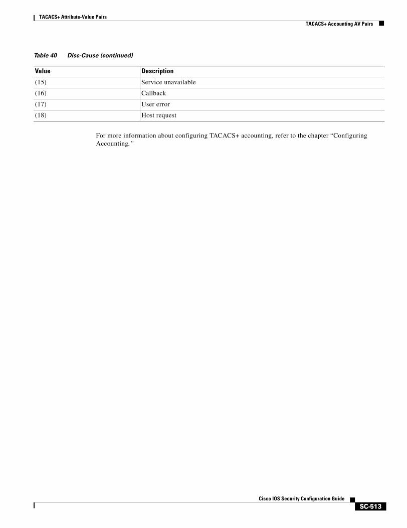
TACACS+ Attribute-Value PairsTACACS+ Accounting AV Pairs
SC-513Cisco IOS Security Configuration Guide
For more information about configuring TACACS+ accounting, refer to the chapter “Configuring Accounting.”
(15) Service unavailable
(16) Callback
(17) User error
(18) Host request
Table 40 Disc-Cause (continued)
Value Description

TACACS+ Attribute-Value PairsTACACS+ Accounting AV Pairs
SC-514Cisco IOS Security Configuration Guide

Index

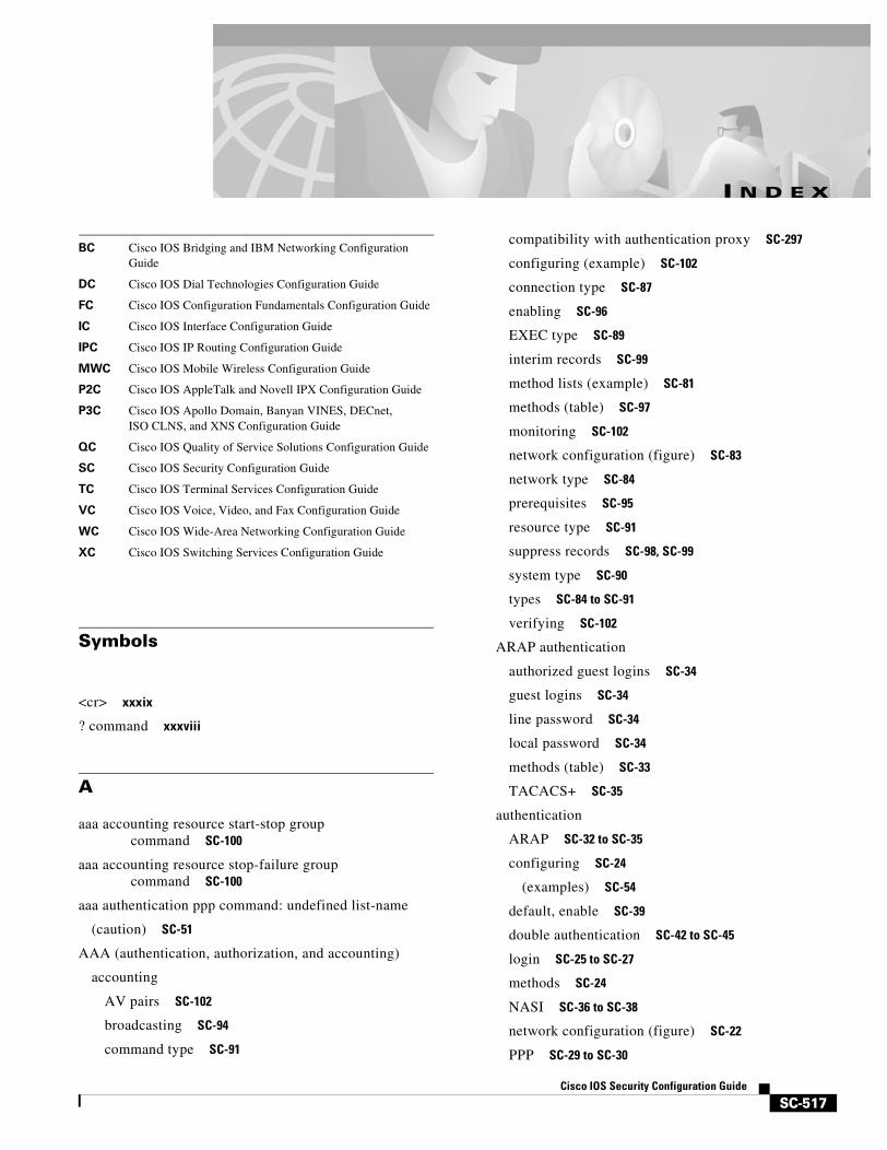
SC-517Cisco IOS Security Configuration Guide
BC Cisco IOS Bridging and IBM Networking Configuration Guide
DC Cisco IOS Dial Technologies Configuration Guide
FC Cisco IOS Configuration Fundamentals Configuration Guide
IC Cisco IOS Interface Configuration Guide
IPC Cisco IOS IP Routing Configuration Guide
MWC Cisco IOS Mobile Wireless Configuration Guide
P2C Cisco IOS AppleTalk and Novell IPX Configuration Guide
P3C Cisco IOS Apollo Domain, Banyan VINES, DECnet, ISO CLNS, and XNS Configuration Guide
QC Cisco IOS Quality of Service Solutions Configuration Guide
SC Cisco IOS Security Configuration Guide
TC Cisco IOS Terminal Services Configuration Guide
VC Cisco IOS Voice, Video, and Fax Configuration Guide
WC Cisco IOS Wide-Area Networking Configuration Guide
XC Cisco IOS Switching Services Configuration Guide
I N D E X
Symbols
<cr> xxxix
? command xxxviii
A
aaa accounting resource start-stop group command SC-100
aaa accounting resource stop-failure group command SC-100
aaa authentication ppp command: undefined list-name
(caution) SC-51
AAA (authentication, authorization, and accounting)
accounting
AV pairs SC-102
broadcasting SC-94
command type SC-91
compatibility with authentication proxy SC-297
configuring (example) SC-102
connection type SC-87
enabling SC-96
EXEC type SC-89
interim records SC-99
method lists (example) SC-81
methods (table) SC-97
monitoring SC-102
network configuration (figure) SC-83
network type SC-84
prerequisites SC-95
resource type SC-91
suppress records SC-98, SC-99
system type SC-90
types SC-84 to SC-91
verifying SC-102
ARAP authentication
authorized guest logins SC-34
guest logins SC-34
line password SC-34
local password SC-34
methods (table) SC-33
TACACS+ SC-35
authentication
ARAP SC-32 to SC-35
configuring SC-24
(examples) SC-54
default, enable SC-39
double authentication SC-42 to SC-45
login SC-25 to SC-27
methods SC-24
NASI SC-36 to SC-38
network configuration (figure) SC-22
PPP SC-29 to SC-30
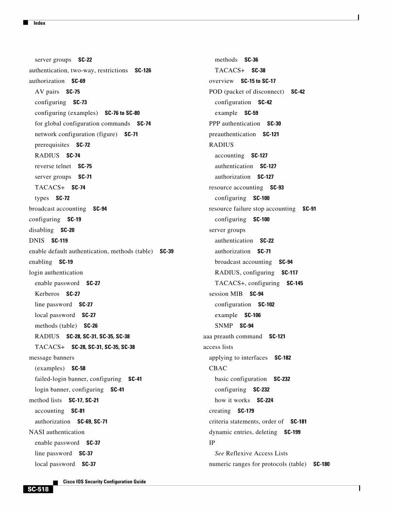
Index
SC-518Cisco IOS Security Configuration Guide
server groups SC-22
authentication, two-way, restrictions SC-126
authorization SC-69
AV pairs SC-75
configuring SC-73
configuring (examples) SC-76 to SC-80
for global configuration commands SC-74
network configuration (figure) SC-71
prerequisites SC-72
RADIUS SC-74
reverse telnet SC-75
server groups SC-71
TACACS+ SC-74
types SC-72
broadcast accounting SC-94
configuring SC-19
disabling SC-20
DNIS SC-119
enable default authentication, methods (table) SC-39
enabling SC-19
login authentication
enable password SC-27
Kerberos SC-27
line password SC-27
local password SC-27
methods (table) SC-26
RADIUS SC-28, SC-31, SC-35, SC-38
TACACS+ SC-28, SC-31, SC-35, SC-38
message banners
(examples) SC-58
failed-login banner, configuring SC-41
login banner, configuring SC-41
method lists SC-17, SC-21
accounting SC-81
authorization SC-69, SC-71
NASI authentication
enable password SC-37
line password SC-37
local password SC-37
methods SC-36
TACACS+ SC-38
overview SC-15 to SC-17
POD (packet of disconnect) SC-42
configuration SC-42
example SC-59
PPP authentication SC-30
preauthentication SC-121
RADIUS
accounting SC-127
authentication SC-127
authorization SC-127
resource accounting SC-93
configuring SC-100
resource failure stop accounting SC-91
configuring SC-100
server groups
authentication SC-22
authorization SC-71
broadcast accounting SC-94
RADIUS, configuring SC-117
TACACS+, configuring SC-145
session MIB SC-94
configuration SC-102
example SC-106
SNMP SC-94
aaa preauth command SC-121
access lists
applying to interfaces SC-182
CBAC
basic configuration SC-232
configuring SC-232
how it works SC-224
creating SC-179
criteria statements, order of SC-181
dynamic entries, deleting SC-199
IP
See Reflexive Access Lists
numeric ranges for protocols (table) SC-180
Index
SC-519Cisco IOS Security Configuration Guide
overview SC-177
specifying
by name SC-180
by number (table) SC-180
See also IKE; IPSec, access lists; IPSec, crypto access lists
access-enable command SC-195
access-list command SC-193
access-list (encryption) command SC-342
access-list (IP extended) command SC-195
address command SC-388
addressed-key command SC-372, SC-388
AH (authentication header) SC-335
algorithms
See IKE, algorithms
antireplay security service SC-335, SC-379
attack signatures
See Cisco IOS Firewall IDS
audit rule
See Cisco IOS Firewall IDS, audit rule
audit trails
CBAC messages SC-249
DNSIX facility SC-426
See also CBAC, audit trail
authentication
CAs SC-369
neighbor router
benefits SC-417
configuration information for protocols SC-421
key chains SC-420
MD5 SC-418, SC-419
plain text SC-418, SC-419
process SC-418
protocols SC-418
types SC-418
non-AAA methods SC-47, SC-48
route SC-12
route authentication SC-417
user, overview SC-11
See also IKE, extended authentication; lock-and-key
authentication command SC-385
authentication proxy SC-3, SC-289
accounting SC-297
applying SC-295
cache entries, deleting SC-307
CBAC requirement SC-299
comparison with Lock-and-Key feature SC-298
compatibility
with CBAC SC-297
with NAT SC-297
with VPN SC-297
configuration tasks SC-300
denial-of-service attack protection SC-298
dynamic ACL entries, displaying SC-306
(examples) SC-307 to SC-320
HTTP trigger SC-290
login page (figure) SC-291
login status message (figure) SC-292
maintaining SC-306
monitoring SC-306
operation
with JavaScript SC-292
without JavaScript SC-292
passwords, one-time SC-295, SC-296
prerequisites SC-299
restrictions SC-299
secure authentication SC-292
spoofing, risk of SC-298
using SC-293
verifying configuration SC-300, SC-303
when to use SC-293, SC-294
authentication proxy operation using one-time passwords SC-296
autocommand command SC-195
B
broadcast accounting SC-94
Index
SC-520Cisco IOS Security Configuration Guide
C
carriage return (<cr>) xxxix
CAs (certification authorities)
authenticating SC-369
certificate revocation SC-364
configuration, saving SC-370
configuring (example) SC-374
declaring SC-367
(example) SC-374
description SC-361
domain names, configuring (example) SC-366, SC-374
host names SC-366
configuring (example) SC-374
identity, deleting SC-373
interoperability SC-332
IPSec, implementing SC-362 to SC-364
LDAP support SC-367
NVRAM memory usage SC-365
prerequisites SC-361
public keys SC-369
purpose SC-361
restrictions SC-361
supported standards SC-360
URLs, specifying SC-367
See also certificates; CRLs; IPSec; RAs
cautions
access lists SC-193
authenticating keys SC-419
Java blocking SC-238
lock-and-key SC-194
neighbor authentication SC-419
passwords, encrypting SC-405
ppp, disabling with undefined list-name SC-51
Unicast RPF
BGP optional attributes SC-435
logging impact SC-433
cautions, usage in text xxxii
CBAC (Context-based Access Control)
limitations
See also CBAC, restrictions
access lists
configuring SC-232
contents, displaying SC-242
how it works SC-224
application-layer protocols, configuring SC-237
audit trail SC-240
audit trail messages
enabling SC-246
(example) SC-249
authentication proxy compatibility SC-299
configuring SC-230 to SC-240
(example) SC-250 to SC-267
guidelines SC-241
verifying SC-242
viewing SC-242
debugging SC-246 to SC-247
denial-of-service attacks
detection SC-234
error messages SC-248
indications SC-236
disabling SC-250
error messages
audit trail SC-249
denial-of-service attacks SC-248
FTP attacks SC-249
Java blocking SC-249
SMTP attacks SC-248
firewall, configuring SC-241
FTP attacks, error messages SC-249
FTP traffic SC-229
H.323 inspection
configuring SC-237
multimedia support SC-227
half-open sessions SC-236
how it works SC-222
inspection rules
applying SC-240
Index
SC-521Cisco IOS Security Configuration Guide
defining SC-236 to SC-239
viewing SC-242
interfaces
choosing SC-230
external, tips SC-234
internal, tips SC-234
intrusion detection SC-221
IP packet fragmentation SC-238
inspection SC-238
IPSec compatibility SC-229
Java
blocking SC-220, SC-238
(caution) SC-238
inspection, configuring SC-238
messages SC-249
logging SC-240
memory usage SC-229
multimedia support protocol inspection SC-227
packet inspection SC-223
PAM operation SC-324
process SC-225
protocol support (table) SC-226
restrictions SC-229
See also CBAC limitations
RPC inspection, configuring SC-237
RTSP inspection SC-227
session information, viewing SC-242
SMTP attacks
error messages SC-248
state tables SC-224
TCP inspection, configuring SC-239
thresholds SC-234, SC-235
timeouts SC-234, SC-235
traffic filtering SC-220
UDP inspection, configuring SC-239
UDP sessions SC-224
when to use SC-225
certificate chain configuration mode, enabling SC-372
certificate command SC-372
certificates SC-360, SC-379
deleting SC-372
requests SC-369
resending SC-367
RSA key requirements SC-367
saving SC-366
storing SC-365
viewing SC-373
See also CAs; CRLs; RSA keys
changed information in this release xxxi
CHAP (Challenge Handshake Authentication Protocol)
authentication SC-49 to SC-52
common password SC-52
delay authentication SC-53
description SC-49
enable authentication SC-50
refuse authentication requests SC-52
Cisco IOS configuration changes, saving xlii
Cisco IOS Firewall
authentication proxy SC-289
description SC-183
dynamic access lists SC-191
feature set SC-184
firewall solution SC-183
reflexive access lists SC-201
See also authentication proxy; CBAC; PAM; TCP intercept
TCP intercept SC-213
Cisco IOS Firewall IDS SC-269, SC-271
audit rule SC-271
compatibility SC-270
configuration (examples) SC-284 to SC-287
configuring SC-278 to SC-283
configuring, initializing, post office SC-279
event logging SC-270
monitoring and maintaining SC-283
performance impact SC-272
process SC-271
sensor SC-270
Index
SC-522Cisco IOS Security Configuration Guide
signature list SC-273 to SC-278
signature types SC-273
threats, response to SC-270
usage scenarios SC-272
when to use SC-271
Cisco Secure IDS
See Cisco IOS Firewall IDS, compatibility
clear access-template command SC-199
clear crypto isakmp command SC-396
clear crypto sa command SC-356
command modes, understanding xxxvii to xxxviii
command syntax
conventions xxxi
displaying (example) xxxix
commands
context-sensitive help for abbreviating xxxviii
default form, using xli
no form, using xli
config-isakmp command mode, enabling SC-385
configurations, saving xlii, SC-370
crl optional command SC-368
crl query command SC-368, SC-371
CRLs (certificate revocation lists)
downloading SC-370, SC-371
missing SC-368
querying SC-368, SC-371
requesting SC-370
saving SC-366
storing SC-365
crypto ca authenticate command SC-369
crypto ca certificate chain command SC-372
crypto ca certificate query command SC-366
crypto ca crl request command SC-371
crypto ca enroll command SC-370
crypto ca identity command SC-367, SC-373
crypto ca trusted-root command SC-368
crypto dynamic-map command SC-353, SC-395
crypto ipsec security-association lifetime command SC-341
crypto ipsec transform-set command SC-346
crypto isakmp enable command SC-382, SC-385
crypto isakmp identity command SC-387
crypto isakmp key command SC-389
crypto key generate rsa command SC-367, SC-387
crypto key pubkey-chain rsa command SC-372, SC-388
crypto key zeroize rsa command SC-371
crypto map client authentication list command SC-393
crypto map command SC-350, SC-351
crypto map configuration, viewing SC-396
crypto map isakmp authorization list command SC-391
D
data authentication SC-335
data confidentiality SC-336
data flow SC-336
debug crypto isakmp command SC-396
debug ip inspect command SC-246
denial-of-service attacks
CBAC detection SC-234
half-open sessions SC-236
detection of
authentication proxy SC-298
using Cisco IOS Firewall IDS SC-273
IP address spoofing, mitigating SC-436
preventing
reflexive access lists SC-202
using TCP Intercept SC-213
Unicast RPF, deploying SC-436
DES (Data Encryption Standard) SC-335, SC-379
IKE policy parameter SC-383
DH (Diffie-Hellman)
See IKE, DH (Diffie-Hellman)
DMDP (DNSIX Message Deliver Protocol) definition SC-427
DNIS (Dialed Number Identification Service)
DNIS number SC-146
preauthentication, configuring SC-121
Index
SC-523Cisco IOS Security Configuration Guide
server groups, selecting SC-119, SC-146
DNSIX (Department of Defense Intelligence Information System Network Security for Information Exchange)
audit trail facility SC-426
DMDP SC-427
enabling SC-427
hosts to receive messages SC-427
IPSO fields, extended SC-425
Network Audit Trail Protocol SC-427
transmission parameters SC-427
dnsix-dmdp retries command SC-427
dnsix-nat authorized-redirection command SC-427
dnsix-nat primary command SC-427
dnsix-nat secondary command SC-427
dnsix-nat source command SC-427
dnsix-nat transmit-count command SC-427
documentation
conventions xxxi
feedback, providing xxxiii
modules xxvii to xxix
online, accessing xxxii
ordering xxxiii
Documentation CD-ROM xxxiii
documents and resources, supporting xxx
domain names
certification authority interoperability
(example) SC-374
certification authority interoperability, configuring SC-366
double authentication
access user profile SC-44
configuring SC-43, SC-45
operation SC-42
dynamic crypto maps
See IPSec, crypto maps
E
encapsulations, IPSec-supported SC-338
encrypted nonces
See RSA encrypted nonces
encryption algorithm
See IKE, algorithms
encryption command SC-385
enrollment mode ra command SC-367
enrollment retry-count command SC-367
enrollment retry-period command SC-367
enrollment url command SC-367
ESP (encapsulating security payload) SC-335
F
Feature Navigator
See platforms, supported
filtering
See access lists
filtering output, show and more commands xlii
firewalls SC-183
CBAC guidelines for SC-241
Cisco IOS Firewall
feature set SC-184
solution SC-183
configuring SC-183
creating SC-184
features SC-184, SC-185
guidelines SC-188
See also CBAC; Cisco IOS Firewall
FTP attacks
CBAC error messages SC-249
G
global configuration mode, summary of xxxviii
group command SC-385
Index
SC-524Cisco IOS Security Configuration Guide
H
H.323 inspection
multimedia protocol support SC-227
See also CBAC, H.323 inspection
hardware platforms
See platforms, supported
hash algorithm
See IKE, algorithms
hash command SC-385
help command xxxviii
hijacking, preventing SC-12
host names
certification authority interoperability
configuring (example) SC-374
certification authority interoperability, configuring (examples) SC-366
hostname command SC-366
I
identification support, configuring SC-413
IDS
See Cisco IOS Firewall IDS
IKE (Internet Key Exchange) security protocol
access lists, configuring SC-382
algorithms
encryption SC-385
hash SC-385
options SC-384
anti-replay SC-379
authentication
methods SC-384, SC-385
connections, clearing SC-396
debug messages SC-396
description SC-332
DH (Diffie-Hellman) SC-379
group identifier, specifying SC-385
IKE policy parameter SC-383
disabling SC-382
enabling SC-382
extended authentication SC-392
configuring (examples) SC-392
purpose SC-392
feature SC-377
group identifier, specifying SC-385
ISAKMP identity, configuring SC-387
keys
See keys, preshared
See keys, preshared; keys, preshared using AAA server; RSA keys
mode configuration SC-391, SC-392
negotiations SC-383
policies
configuring (example) SC-397
creating SC-382 to SC-386
defaults, viewing SC-385
identifying SC-385
multiple SC-385
parameters SC-383, SC-384, SC-396
purpose SC-382
requirements SC-382
viewing SC-385
preshared keys using AAA server, configuring (example) SC-397
protocol SC-334, SC-378
requirements
access lists SC-382
policies SC-382
RSA encrypted nonces method SC-386
RSA signatures method SC-386
SAs SC-380
supported standards SC-378
troubleshooting SC-396
tunnel endpoint discovery (TED)
description SC-393
restrictions SC-395
versions SC-394
Index
SC-525Cisco IOS Security Configuration Guide
See also IPSec; RSA encrypted nonces; SAs
indexes, master xxx
inspection rules SC-236
See CBAC, inspection rules
interface command SC-195
interface configuration mode, summary of xxxviii
intrusion detection
See Cisco IOS Firewall IDS
IP
access lists
dynamic, deleting SC-199
reflexive SC-201
encryption SC-12
security
See also lock-and-key; TCP Intercept SC-192
session filtering
See Reflexive Access Lists
ip access-group command SC-195
ip domain-name command SC-366
ip inspect audit trail command SC-246
ip inspect command SC-240
ip inspect dns-timeout command SC-235
ip inspect max-incomplete high command SC-235
ip inspect max-incomplete low command SC-235
ip inspect name command SC-237
ip inspect one-minute high command SC-235
ip inspect one-minute low command SC-235
ip inspect tcp finwait-time command SC-235
ip inspect tcp idle-time command SC-235
ip inspect tcp max-incomplete host command SC-235
ip inspect tcp synwait-time command SC-235
ip inspect udp idle-time command SC-235
IP packet fragmentation
See CBAC, IP packet fragmentation
ip port-map command SC-325
ip security add command SC-424
ip security aeso command SC-426
ip security dedicated command SC-424
ip security eso-info command SC-426
ip security eso-max command SC-426
ip security eso-min command SC-426
ip security extended-allowed command SC-424
ip security first command SC-425
ip security ignore-authorities command SC-424
ip security implicit-labelling command SC-424
ip security multilevel command SC-424
ip security reserved-allowed command SC-425
ip security strip command SC-424
ip tcp intercept connection-timeout command SC-216
ip tcp intercept drop-mode command SC-215
ip tcp intercept finrst-timeout command SC-216
ip tcp intercept list command SC-214
ip tcp intercept max-incomplete high command SC-217
ip tcp intercept max-incomplete low command SC-217
ip tcp intercept mode command SC-215
ip tcp intercept one-minute high command SC-217
ip tcp intercept one-minute low command SC-217
ip tcp intercept watch-timeout command SC-215
IPSec (IPSec network security protocol)
access lists SC-338
requirements SC-340
benefits SC-331
CAs
implementing with SC-363, SC-364
implementing without SC-362, SC-364
CBAC compatibility SC-229
configuration
(example) SC-357
configuring SC-356
crypto access lists SC-342
any keyword, using SC-345
creating SC-342
manually established SAs SC-344
mirror images SC-344
purpose SC-342
tips SC-343
crypto maps
applying SC-355
Index
SC-526Cisco IOS Security Configuration Guide
dynamic
adding SC-355
creating SC-352, SC-353
definition SC-352
entries, creating SC-348 to SC-355
purpose SC-348
quantity SC-349
encapsulations supported SC-338
feature SC-333
hardware supported SC-337
how it works SC-338
monitoring SC-356
multiple peers SC-339
NAT, configuring SC-338
network services SC-12, SC-333
prerequisites SC-340
protocol SC-334
requirements for SAs SC-380
restrictions SC-338
SAs
clearing SC-347
IKE negotiations SC-338, SC-351
manual negotiations SC-339, SC-349
supported standards SC-334
switching paths supported SC-337
traffic protected, defining SC-338
transform sets SC-346
configuring (example) SC-374
transforms SC-336
tunnel endpoint discovery
See IKE, tunnel endpoint discovery
IPSO (IP Security Option)
basic SC-424
basic security classifications SC-424
(examples) SC-428
extended
AESOs, attaching SC-426
configuration tasks SC-426
ESOs, attaching SC-426
global defaults SC-426
ISAKMP SC-378
See also IKE SC-377
J
Java blocking
See CBAC, Java
K
Kerberos
authentication SC-161
login SC-27
PPP SC-30
configuring
credential forwarding SC-161
(examples) SC-164 to SC-174
instance mapping SC-163
KDC (key distribution center) SC-157
database SC-158
mandatory authentication SC-163
network access server communication SC-159
realms SC-160
SRVTABs files, copying SC-160
SRVTABs, creating SC-158
SRVTABs, extracting SC-159
Encrypted Kerberized Telnet SC-162
maintaining SC-164
monitoring SC-164
operation SC-155 to SC-157
Telnet to router SC-162
terms (table) SC-154
keys
chains SC-420
management SC-420
preshared
configuring (example) SC-389, SC-397
Index
SC-527Cisco IOS Security Configuration Guide
IKE policy parameter SC-383
ISAKMP identity, configuring SC-387
masks SC-389
specifying SC-389
preshared using AAA server SC-390
configuring SC-391
key-string command SC-388
L
LDAP (Lightweight Directory Access Protocol) support, specifying SC-367
lifetime command SC-385
line vty command SC-195
lock-and-key SC-192
benefits SC-192
configuring
(examples) SC-199 to SC-200
guidelines SC-196
prerequisites SC-194
verification SC-198
maintenance tasks SC-198
performance impacts SC-194
process SC-193
spoofing, risk of SC-194
when to use SC-192
logging
See CBAC logging and audit trail
login local command SC-195
login tacacs command SC-195
M
mask preshared keys SC-389
match address command SC-351, SC-354
MD5 (Message Digest 5) algorithm SC-335, SC-379
IKE policy parameter SC-383
neighbor router authentication SC-419
memory usage and certification authority interoperability SC-365
method lists
AAA
accounting SC-81
authentication SC-21
authorization SC-69, SC-71
description SC-17
(example) SC-18
MIB, descriptions online xxx
modes
certificate chain configuration, enabling SC-372
public key configuration, enabling SC-372
query, enabling SC-366
RA, enabling SC-367
See command modes
MS-CHAP (Microsoft Challenge Handshake Authentication Protocol)
configuration example SC-67
feature summary SC-53
multimedia application protocol support
H.323 SC-228
protocols (table) SC-226
RTSP SC-227
N
named-key command SC-372, SC-388
NAT, configuring IPSec for SC-338
neighbor router authentication
See authentication, neighbor router
new information in this release xxxi
no ip inspect command SC-250
nonces
See RSA encrypted nonces
nonrepudiation SC-380
notes, usage in text xxxii
O
Oakley key exchange protocol SC-378
Index
SC-528Cisco IOS Security Configuration Guide
See also IKE
P
packet fragmentation
See CBAC, IP packet fragmentation
PAM (port to application mapping)
CBAC operation SC-322
configuration examples SC-326 to SC-327
configuring
access lists SC-325
port mapping SC-325
verifying SC-325
default port mapping SC-322
host-defined mapping SC-322
host-specific mapping SC-324
how PAM works SC-321
mapping information, saving SC-323
mapping types
host-specific SC-322, SC-324
system-defined SC-322
user-defined SC-322, SC-323
monitoring and maintaining SC-326
operation with CBAC SC-322, SC-324
port range, defining SC-323
registered ports SC-322
system-defined mapping
deleting SC-322
overriding SC-322, SC-324
port numbers (table) SC-322
registered ports SC-322
table SC-322
well-known ports SC-322
table SC-322
user-defined mapping SC-322, SC-323
verifying SC-325
well-known ports SC-322
when to use SC-324
PAP (Password Authentication Protocol)
authentication SC-49 to SC-52
description SC-49
enable authentication SC-50
outbound authentication SC-51
refuse authentication request SC-52
password command SC-195
passwords
configuration (examples) SC-414 to SC-416
configuring
enable password SC-404
enable secret SC-404
line password SC-405
static enable password SC-404
encrypting SC-405
(caution) SC-405
recovering lost enable passwords
procedure 1 SC-409
procedure 2 SC-410
procedures (tables) SC-408
process SC-408
recovering lost line passwords
diagnostic mode settings (table) SC-413
peer description SC-336
PFS (perfect forward secrecy) SC-336, SC-380
plain text authentication
See authentication, neighbor router
platforms, supported
Feature Navigator, identify using xliii
release notes, identify using xliii
POD (packet of disconnect)
See AAA, POD
PPP
enable encapsulation SC-50
inbound authentication SC-51
outbound authentication SC-51
preauthentication, configuring SC-137
preshared keys
See keys, preshared; keys, preshared using AAA server
privileged EXEC mode, summary of xxxviii
Index
SC-529Cisco IOS Security Configuration Guide
privileges
changing default SC-407
configuring SC-406
(examples) SC-414 to SC-416
displaying current level SC-407
logging in SC-407
prompts, system xxxviii
protocol support, CBAC (table) SC-226
provide SC-201
public key configuration mode, enabling SC-372, SC-388
Q
query mode, enabling SC-366
query url command SC-367
question mark (?) command xxxviii
R
RA mode, enabling SC-367
RADIUS
accounting SC-127
attributes 463
IETF 470
vendor-proprietary SC-124, SC-129, SC-130
vendor-specific SC-124
attribute-value pairs SC-123
authentication SC-127
authorization SC-127
authorization of SC-74
configuration (examples) SC-130 to SC-139
configuration tasks SC-111
configuring
attributes, vendor-proprietary SC-115
attributes, vendor-specific SC-114
communication, global SC-113
communication, per-server SC-113
DNIS preauthentication SC-122
DNIS server group selection SC-119
guard timer SC-127
NAS port types, displaying SC-116
password, username SC-129
preauthentication profiles SC-122
queries for IP addresses SC-116
queries for static routes SC-116
RADIUS prompt SC-128
server communication SC-112
server groups SC-117
server groups, deadtime for SC-119
server groups, DNIS selection of SC-119
suffix, username SC-129
UDP ports SC-112
username SC-129
login authentication SC-28, SC-31, SC-35, SC-38
Login-IP-Host SC-128
operation SC-110
overview SC-109
preauthentication profiles
call type SC-123
callback SC-123
CLID SC-122
DNIS SC-122
modem management SC-124
subsequent authentication SC-124
two-way authentication SC-125
username SC-125
server groups
deadtime SC-118
description SC-117
DNIS selection of SC-119
radius-server attribute 44 include-in-access-req command SC-31
radius-server attribute 8 include-in-access-req command SC-28
RAs (registration authorities)
See CAs
Reflexive Access Lists

Index
SC-530Cisco IOS Security Configuration Guide
benefits SC-202
configuring SC-206 to SC-209
(examples) SC-209 to SC-211
how it works SC-203
restrictions SC-204
session filtering
basic access lists SC-202
reflexive access lists SC-202
topology
DMZ (figure) SC-205
simple (figure) SC-205
where to configure SC-203
release notes
See platforms, supported
repudiation SC-380
RFC
full text, obtaining xxx
RFC 1108, IP Security Options SC-423
RFC 1323, window scaling SC-214
RFC 1334, PPP Authentication Protocols SC-49
RFC 1413, Identification Protocol SC-413
RFC 1829, The ESP DES-CBC Transform SC-335
RFC 1994, PPP CHAP SC-53
RFC 2138, RADIUS SC-130
RFC 2139, RADIUS Accounting SC-130
RFC 2401, Security Architecture for the Internet Protocol SC-334
RFC 2402, IP Authentication Header SC-334
RFC 2408, ISAKMP SC-378
RFC 2409, The Internet Key Exchange SC-378
RFC 2410, The NULL Encryption Algorithm and Its Use with IPsec SC-334
RFC 2865, RADIUS SC-130
RFC 2868, RADIUS Attributes for Tunnel Protocol Support SC-130
ROM monitor mode, summary of xxxviii
root PROXY command SC-369
root SCEP command SC-369
root TFTP command SC-369
route authentication SC-417
RPF
See Unicast RPF
RSA (Rivest, Shamir, and Adelman) encrypted nonces SC-379
IKE policy parameter SC-383
requirements SC-384, SC-386
RSA (Rivest, Shamir, and Adelman) keys SC-360
configuring, manually SC-386
deleting SC-371, SC-372
generating SC-367, SC-387
purpose SC-367
specifying SC-388
viewing SC-373, SC-388
See also certificates; certification authority interoperability SC-367
RSA (Rivest, Shamir, and Adelman) signatures SC-379
IKE policy parameter SC-383
requirements SC-384
IKE configuration SC-386
RTSP (Real Time Streaming Protocol), CBAC inspection and support of SC-227
S
SAs (security associations) SC-336, SC-380
clearing SC-341, SC-356
establishing SC-380
IKE established crypto map entries, creating SC-351
lifetimes
configuring SC-385
global values, configuring SC-340
how they work SC-341
IKE policy parameter SC-383
manually established
crypto access lists, defining SC-344
crypto map entries, creating SC-349
viewing SC-396
scalability, configuring (example) SC-57
security
Index
SC-531Cisco IOS Security Configuration Guide
IP
denial-of-service attacks SC-213, SC-441
IPSO SC-423
TCP SYN-flooding attacks SC-213, SC-441
neighbor router authentication SC-417
policies
creating SC-6
nature of SC-6
tips SC-7
risks SC-9
See also access lists; authentication; IPSec
IP
See also DNSIX; lock-and-key; Reflexive Access Lists; TCP Intercept
security features SC-1
server groups
AAA, authentication SC-22
AAA, authorization SC-71
deadtime, configuring SC-118
RADIUS, configuring SC-117
TACACS+, configuring SC-145
server groups, AAA
broadcast accounting SC-94
session filtering
See Reflexive Access Lists
set peer command SC-350, SC-351, SC-354
set pfs command SC-352, SC-354, SC-395
set security-association level per-host command SC-351
set security-association lifetime command SC-351, SC-354, SC-395
set session-key command SC-350
set transform-set command SC-350, SC-351, SC-353
SHA (Secure Hash Algorithm) SC-335, SC-379
IKE policy parameter SC-383
show access-lists command SC-198
show crypto ca certificates command SC-373
show crypto ca roots command SC-373
show crypto dynamic-map command SC-356
show crypto ipsec sa command SC-356
show crypto ipsec security-association lifetime command SC-356
show crypto ipsec transform-set command SC-356
show crypto isakmp policy command SC-385, SC-396
show crypto isakmp sa command SC-396
show crypto key mypubkey rsa command SC-373, SC-387
show crypto key pubkey-chain rsa command SC-373, SC-388
show crypto map command SC-356
show ip inspect command SC-242
show ip port-map command SC-326
show tcp intercept connections command SC-217
show tcp intercept statistics command SC-217
signatures
attack SC-269
list
See Cisco IOS Firewall IDS, signature list; RSA signatures
Skeme key exchange protocol SC-378
See also IKE
SMTP attacks
CBAC error messages SC-248
CBAC intrusion detection SC-221
SPI (security parameter index) SC-336
spoofing attacks
See also Reflexive Access Lists
spoofing attacks, preventing SC-202
SSH (Secure Shell Version 1) SC-5
client
DES and 3DES support SC-450
description SC-450
examples (See ssh command)
server support SC-450
configuring
(examples) SC-454 to SC-458
prerequisites SC-451
troubleshooting SC-454
verifying SC-453
maintaining SC-454
monitoring SC-454
Index
SC-532Cisco IOS Security Configuration Guide
prerequisites SC-451
restrictions SC-450
server SC-450
troubleshooting SC-454
verifying SC-453
standards
IKE, supported by SC-378
switching paths, IPSec supported SC-337
T
Tab key, command completion xxxviii
TACACS+
accounting SC-148
attribute-value pairs
See AV pairs
authentication
login SC-28, SC-31, SC-35, SC-38
NASI SC-38
authorization SC-147
AV pairs SC-148, SC-499 to SC-508
accounting SC-508
configuring
authentication SC-147
authentication key SC-145
DNIS, server group selection SC-146
(examples) SC-148 to SC-152
server groups SC-145
DNIS selection SC-146
server host SC-144
login input time, configuring SC-39
operation SC-142
overview SC-141
server groups SC-145
DNIS selection SC-146
TCP filtering
See CBAC
TCP Intercept
configuring, (example) SC-217
connections, displaying SC-217
modes SC-215
monitoring and maintaining SC-217
overview SC-213
statistics, displaying SC-217
thresholds SC-216
timeouts SC-215
TCP SYN-flooding attacks
preventing SC-213
thresholds
See CBAC, thresholds
timeout intervals
See CBAC, timeouts
traffic filtering
See access lists; CBAC, traffic filtering
transform
See IPSec, transforms
trusted root
CEP
configuring
(example) SC-376
configuring SC-368
(example) SC-376
CRLs, querying SC-368, SC-371
obtaining SC-369
SCEP
configuring SC-369
TFTP
configuring SC-369
(example) SC-376
tunnel endpoint discovery (TED)
description SC-393
restrictions SC-395
See also IKE, tunnel endpoint discovery
versions SC-394
U
UDP filtering

Index
SC-533Cisco IOS Security Configuration Guide
See CBAC
Unicast RPF (Unicast Reverse Path Forwarding)
ACLs
events, logging SC-433
packets
dropping SC-433
forwarding SC-433
aggregation routers (figure) SC-439
applying SC-436
BGP attributes
caution SC-435
CEF
requirement SC-432
tables SC-439
configuring SC-442
aggregation routers (figure) SC-439
BOOTP SC-440
DHCP SC-440
enterprise network (figure) SC-437
(examples) SC-446 to SC-447
prerequisites SC-442
routing table requirements SC-439
tasks SC-442
troubleshooting SC-444
verifying SC-444
deploying SC-436
description SC-5, SC-431
disabling SC-445
enterprise network (figure) SC-437
FIB SC-432
implementing SC-435
maintaining SC-445
monitoring SC-445
packets, dropping (figure) SC-435
per-interface statistics
packets
dropped SC-433
suppressed drop SC-433
prerequisites SC-442
restrictions
basic SC-440
routing asymmetry SC-439
routing asymmetry (figure) SC-440
routing table requirements SC-439
security policy
applying SC-436
attacks, mitigating SC-436
deploying SC-436
tunneling SC-436
source addresses, validating SC-433
failure SC-434
(figure) SC-434, SC-435
traffic filtering SC-436
troubleshooting SC-444
tunneling SC-436
validation
failure SC-434, SC-435
packets, dropping SC-434
source addresses SC-434
verifying SC-444
user EXEC mode, summary of xxxviii
username command SC-48
X
Xauth
See IKE, extended authentication