Embed Size (px)
Citation preview
Cisco Lean Retail Oracle Siebel 8 Application Deployment GuideCisco Validated Design
April 14, 2008
Americas HeadquartersCisco Systems, Inc.170 West Tasman DriveSan Jose, CA 95134-1706 USAhttp://www.cisco.comTel: 408 526-4000
800 553-NETS (6387)Fax: 408 527-0883
Customer Order Number: Text Part Number:
Cisco Validated DesignThe Cisco Validated Design Program consists of systems and solutions designed, tested, and documented to facilitate faster, more reliable, and more predictable customer deployments. For more information visit www.cisco.com/go/validateddesigns.
ALL DESIGNS, SPECIFICATIONS, STATEMENTS, INFORMATION, AND RECOMMENDATIONS (COLLECTIVELY, "DESIGNS") IN THIS MANUAL ARE PRESENTED "AS IS," WITH ALL FAULTS. CISCO AND ITS SUPPLIERS DISCLAIM ALL WARRANTIES, INCLUDING, WITHOUT LIMITATION, THE WARRANTY OF MERCHANTABILITY, FITNESS FOR A PARTICULAR PURPOSE AND NONINFRINGEMENT OR ARISING FROM A COURSE OF DEALING, USAGE, OR TRADE PRACTICE. IN NO EVENT SHALL CISCO OR ITS SUPPLIERS BE LIABLE FOR ANY INDIRECT, SPECIAL, CONSEQUENTIAL, OR INCIDENTAL DAMAGES, INCLUDING, WITHOUT LIMITATION, LOST PROFITS OR LOSS OR DAMAGE TO DATA ARISING OUT OF THE USE OR INABILITY TO USE THE DESIGNS, EVEN IF CISCO OR ITS SUPPLIERS HAVE BEEN ADVISED OF THE POSSIBILITY OF SUCH DAMAGES.
THE DESIGNS ARE SUBJECT TO CHANGE WITHOUT NOTICE. USERS ARE SOLELY RESPONSIBLE FOR THEIR APPLICATION OF THE DESIGNS. THE DESIGNS DO NOT CONSTITUTE THE TECHNICAL OR OTHER PROFESSIONAL ADVICE OF CISCO, ITS SUPPLIERS OR PARTNERS. USERS SHOULD CONSULT THEIR OWN TECHNICAL ADVISORS BEFORE IMPLEMENTING THE DESIGNS. RESULTS MAY VARY DEPENDING ON FACTORS NOT TESTED BY CISCO.
CCVP, the Cisco Logo, and the Cisco Square Bridge logo are trademarks of Cisco Systems, Inc.; Changing the Way We Work, Live, Play, and Learn is a service mark of Cisco Systems, Inc.; and Access Registrar, Aironet, BPX, Catalyst, CCDA, CCDP, CCIE, CCIP, CCNA, CCNP, CCSP, Cisco, the Cisco Certified Internetwork Expert logo, Cisco IOS, Cisco Press, Cisco Systems, Cisco Systems Capital, the Cisco Systems logo, Cisco Unity, Enterprise/Solver, EtherChannel, EtherFast, EtherSwitch, Fast Step, Follow Me Browsing, FormShare, GigaDrive, GigaStack, HomeLink, Internet Quotient, IOS, iPhone, IP/TV, iQ Expertise, the iQ logo, iQ Net Readiness Scorecard, iQuick Study, LightStream, Linksys, MeetingPlace, MGX, Networking Academy, Network Registrar, Packet, PIX, ProConnect, RateMUX, ScriptShare, SlideCast, SMARTnet, StackWise, The Fastest Way to Increase Your Internet Quotient, and TransPath are registered trademarks of Cisco Systems, Inc. and/or its affiliates in the United States and certain other countries.
All other trademarks mentioned in this document or Website are the property of their respective owners. The use of the word partner does not imply a partnership relationship between Cisco and any other company. (0612R)
Cisco Lean Retail Oracle Siebel 8 © 2008 Cisco Systems, Inc. All rights reserved.
C O N T E N T S
Introduction 1Document Purpose 2Prerequisites 2Document Organization 3
Solution Overview 3Solution Description 3Process Flow 7
Solution Design 7Siebel Application Overview 7Siebel Application Architecture 8
Client Tier 8Application Tier 9Database Tier 9Gateway Name Server 9
Application and Application Networking Design 10Enterprise Store 11WAN Simulation 11Data Center 11Server Farms 12
Packet Flow Without Cisco WAAS and Cisco ACE 13Client Segment 13WAN Segment 13Server Segment 13Response Times 13
Packet Flow with Cisco WAAS and Cisco ACE 14
Implementing and Configuring the Cisco ACE Solution 15Implementation 15
Implementation Overview 15What Was Implemented 15What Was Not Implemented/Tested 15
Network Topology 16Hardware or Components 17Software 17Features and Functionality 17Features, Services, and Application Design Considerations 18
Cisco ACE Virtualization 18Server Farms and Health Probes 18Loadbalancing/TCP Reuse/SSL Termination 18
Scalability and Capacity Planning 18High Availability 19
Cisco ACE High Availability 19
iCisco Lean Retail Oracle Siebel 8
Contents
Server Farm High Availability 19Configuration Task Lists 19
MSFC Configuration 19WebFarm Context Configuration 20
Remote Management Access 20Configuring Interface(s) and Default Gateway 21Probes 22Real Server 23Server Farm 23Layer 7 Load Balancing 23Stickiness (Session Persistence) 24SSL Termination 25
Siebel Application Manager (AOM) Context Configuration 26Virtualization 27Redundancy/High Availability 27Management Access Configuration 28Configuring Interface(s) and Default Gateway 28Probes 29Real Server 29Server Farms 29Layer 7 Load Balancing 30
Configuration and Menus 31Troubleshooting Configuration 32
Implementing and Configuring the Cisco WAAS Solution 32Implementation 32
Implementation Overview 32What Was Implemented 32What Was Not Implemented 33
Network Topology 33Hardware or Components 34Software 34Features and Functionality 34Features, Services, and Application Design Considerations 34Scalability and Capacity Planning 35High Availability 36
Device High Availability 36N+1 Availability 36
Configuration Task Lists 36Central Manager 36Store and Data Center Router 38WAE-612-K9, WAE-7326-K9 39
Configuration and Menus 40Troubleshooting Configuration 41
Cisco WAE Commands 41Router Commands 41
Testing and Results 42Document Attachments 43Site Navigation 44
Summary and Conclusions 45
iiCisco Lean Retail Oracle Siebel 8
Contents
Appendix A—Cisco ACE Configuration 46Admin Context 46WebFarm Context 47Siebel Application Farm (AOM) Context 49
Appendix B—Cisco WAE Configurations 51Store Cisco WAE Configuration 51Data Center Cisco WAE Configuration 52
Appendix C—Cisco ACE Appliance Configuration and Test Results 53Enterprise Store 54WAN Simulation 54Data Center 55
Dual VIP, Single Context 56ACE 4710 Configuration 56
Admin Context 56Siebel Context 57
Test Results 59
Appendix D—Network Management 60
Appendix E—Cisco Advanced Services 62Cisco Services Help Accelerate and Optimize ANS Deployments 62
iiiCisco Lean Retail Oracle Siebel 8

Contents
ivCisco Lean Retail Oracle Siebel 8
Cisco Lean Retail Oracle Siebel 8 Application Deployment Guide
IntroductionThe Cisco Lean Retail Oracle Siebel solution provides best practices and implementation guidance that optimizes application availability, performance, and security while lowering application ownership costs. Cisco’s Lean Retail provides accelerated application performance and faster access to information. Data center-based applications and hosted managed services can have their performance accelerated to LAN-like speeds. Oracle’s Siebel 8 Customer Relationship Management (CRM) enables organizations to transform the customer experience by managing sales, marketing, and customer service across all communication channels and points of customer contact.
Cisco’s Lean Retail Architecture includes:
• Reduced capital and operational costs for applications, servers, and networking
• Application and collaboration services
• Integrated networking services
• Reference network designs
A key Lean Retail integrated network service is the Application Networking Service (ANS). This solution focuses on the ANS components of Cisco Application Control Engine (Cisco ACE) and Wide Area Application Services (WAAS) product families. It provides data center, retail store, and remote end user application optimization services. This collaboration between Oracle and Cisco addresses the following Siebel 8.0 deployment challenges:
• Recovery time objectives (RTO) and recovery point objectives (RPO) for business continuity
• Application response time over limited WAN connections
• Application, server, network, and service-oriented architecture (SOA) security
The value of Cisco’s Lean Retail is accomplished through four key benefits:
• Application availability—When an application server fails in a store, only that store is impacted. When an application fails in a data center, many stores are impacted. A core tenet of Cisco’s Lean Retail is the centralization of application services. Through server virtualization and load balancing,
Americas Headquarters:
© 2007 Cisco Systems, Inc. All rights reserved.
Cisco Systems, Inc., 170 West Tasman Drive, San Jose, CA 95134-1706 USA
Introduction
greater application uptime is achieved. Virtualized server resources in the data center leverage clustering and load balancing to share and distribute load across a larger pool of resources. A single failure does not impact overall accessibility of the application users.
• Performance improvement—Traditionally, retailers use low bandwidth links. Many retailers have hundreds to thousands of stores. The incremental addition of WAN bandwidth per store significantly increases OPEX costs due to economies of scale. Retailers get more for less through the use of virtualized servers, load balancing, and WAAS. Performance is significantly improved for the end user (both in stores and across the Web). Servers are more fully utilized when loads are balanced across larger clusters. WAN performance is improved by locally caching content and accelerating the TCP protocol.
• Increased security—Retailers need to comply with industry and regulatory requirements, e.g., PCI, HIPPA, and SOX, to avoid fines and penalties. Security features including encryption, segmentation, and authentication address many of these requirements. Cisco ACE applies stateful inspection rules that explicitly allow or deny specified traffic patterns. Cisco ACE also uses role-based access control to give independent access to both security and load-balancing policies. The Cisco ACE XML Gateway provides a full Layer 7 proxy and includes integrated XML security for Web services transactions.
• Lowering application ownership costs—Many retailers have hundreds to thousands of stores. Typically they have several servers in each store. For both existing and new applications, the incremental costs per store are significant. By removing servers from the stores, retailers are able to reduce OPEX costs on average of 16%1.
Deploying new applications and capabilities quickly and effectively are key IT metrics that improve an organization’s business agility. Cisco’s Lean Retail enables more applications to be deployed centrally, cutting down dramatically on the time and cost of deployment. Deploying centrally also reduces the costs of opening new stores and of integrating acquisitions. While many retailers will choose to deploy some applications in the stores, the Lean Retail Architecture improves the capabilities of a central deployment model. To learn more about Cisco’s Lean Retail, see:
http://www.cisco.com/web/strategy/retail/lean-retail.html
Document PurposeCisco and Oracle cooperated in all phases of the Cisco Lean Retail for Siebel 8 testing, including lab set-up at Cisco offices, solution functional and performance testing, and this deployment guide. Cisco and Oracle jointly validated that the lab setup and solution testing represents best efforts in creating a realistic customer deployment and accurate documentation of such deployment.
The purpose of this document is to describe the Lean Retail Oracle Siebel 8 Solution enterprise network design, deployment, best practices, and guidance.
PrerequisitesThe following prerequisites are required to deploy the Lean Retail Oracle Siebel 8 Solution:
• Working knowledge of the Siebel 8.0 application
• Experience with basic networking and troubleshooting
• Experience installing the Cisco products covered by this network design, including the Cisco ACE and WAAS product families
1. Gartner: Server consolidation can save money 12/2005.
2
Solution Overview
• Working knowledge of Cisco’s Internetworking Operating System (IOS)
Document OrganizationThe following table provides a brief description of each section.
Solution Overview
Solution DescriptionThe Lean Retail Oracle Siebel 8 Solution offers optimized Siebel 8.0 application availability, performance, security, and cost savings by providing application optimization services as follows:
• Application availability
Cisco ACE product family application optimization services for high Siebel 8.0 availability:
– Application health monitoring—Continuously and intelligently monitors application and database availability.
– Server load balancing—Efficiently routes end user and Web services requests to the best available server.
Section Description
Solution Overview A high-level introduction to the solution. Introduces the solution, historical aspects, potential benefits, and scope and limitations.
Solution Design Describes the design of the Lean Retail Oracle Siebel 8 Solution.
Implementing and Configuring the Cisco ACE Solution
Describes configuration and implementation of Cisco ACE within the Lean Retail Oracle Siebel 8 Solution.
Implementing and Configuring the Cisco WAAS Solution
Describes configuration and implementation of WAAS within the Lean Retail Oracle Siebel 8 Solution.
Appendix A—Cisco ACE Configuration Sample Cisco ACE configuration.
Appendix B—Cisco WAE Configurations Sample Cisco WAW configuration.
Appendix C—Cisco ACE Appliance Configuration and Test Results
Describes the configuration and implementation of Cisco ACE Appliance within the Lean Retail Oracle Siebel 8 Solution.
Appendix D—Network Management Describes the network management software used in the Lean Retail Oracle Siebel 8 Solution.
Appendix E—Cisco Advanced Services Describes the Cisco services available to accelerate deployment of the Lean Retail Oracle Siebel 8 Solution.
3
Solution Overview
– Network platform health monitoring—Ensures continuity of business operations through mirroring end user transaction states across pairs of network devices.
• Application performance
Cisco ACE and WAAS product family application optimization services for Siebel 8.0 high performance:
– WAN optimization—Provides intelligent caching, compression, and protocol optimization that yields as much as 2 times faster performance (see Testing and Results).
– Server offloading—Specialized hardware that offers greater processing efficiency for application optimization services listed below, such as server load balancing, Secure Socket Layer termination, and traffic compression, which frees up to 50 percent of application server processing and memory to focus on business logic computations.
– Server load balancing—Substitutes for Siebel native load balancing.
– Secure Socket Layer (SSL) termination—Terminates 15,000 connections per second.
– Transmission Control Protocol (TCP) connection management—Reduces the number of TCP connections to server.
– Server health monitoring—Substitutes for Siebel native server health monitoring.
– Traffic compression—Scalable LZ compression functionality.
– Object caching—Reduce requests to server.
• Application security
Cisco ACE product family application optimization services for optimized Siebel 8.0 data security:
– SSL termination—Efficiently encrypts and decrypts SSL enabled traffic, which facilitates the use of intrusion detection and prevention solutions before traffic reaches the servers.
– End user access control—Provides Access Control Lists (ACLs) to protect client-to-server traffic from worms and intruders that attack vulnerable open server ports not used by the application.
• Virtualization of application optimization services
Virtualization of application optimization services supplies such services for multiple Oracle and Siebel instances as well as other enterprise applications (see Figure 1). Specifically, a single physical Cisco ACE can be virtualized into multiple logical Cisco ACEs in which application traffic can traverse between virtualized Cisco ACEs. This virtualization of load balancing is an exclusive Cisco feature.
4
Solution Overview
Figure 1 Virtualization of Application Optimization Services
The application optimization services of the Lean Retail Oracle Siebel 8 Solution reside in both the data center and the store to offer end-to-end value, from store and remote users, all the way through to the database and information storage.
• Data center application optimization services
Cisco ACE and WAAS reside in the data center and are arranged to provide virtualized application optimization services for multiple Oracle and Siebel instances as well as other enterprise applications.
Because of their unique location, these solutions can take intelligent action on end-user traffic before it is routed to the Siebel application servers, including server load balancing, server health monitoring, SSL decryption, TCP connection consolidation, and security access control.
While some of these functions could be provided natively by the Siebel application or third party server based solutions, Cisco networking provides these services cost-effectively, freeing up server processing and memory needs to focus on business logic computation.
• Wide area application optimization services
Store Users
MicrosoftSharePoint
Cisco WAAS
Cisco WAAS Cisco ACE Cisco AXG
WAN
Cisco ApplicationNetworking Solutions
Databaseand
Storage
OtherBEAWebLogic
IBMWebSphere
OracleSiebel
Remote Users
Data Center
Web Services
2242
75
5
Solution Overview
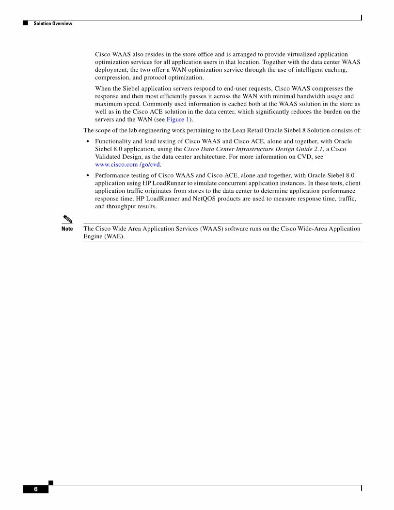
Cisco WAAS also resides in the store office and is arranged to provide virtualized application optimization services for all application users in that location. Together with the data center WAAS deployment, the two offer a WAN optimization service through the use of intelligent caching, compression, and protocol optimization.
When the Siebel application servers respond to end-user requests, Cisco WAAS compresses the response and then most efficiently passes it across the WAN with minimal bandwidth usage and maximum speed. Commonly used information is cached both at the WAAS solution in the store as well as in the Cisco ACE solution in the data center, which significantly reduces the burden on the servers and the WAN (see Figure 1).
The scope of the lab engineering work pertaining to the Lean Retail Oracle Siebel 8 Solution consists of:
• Functionality and load testing of Cisco WAAS and Cisco ACE, alone and together, with Oracle Siebel 8.0 application, using the Cisco Data Center Infrastructure Design Guide 2.1, a Cisco Validated Design, as the data center architecture. For more information on CVD, see www.cisco.com /go/cvd.
• Performance testing of Cisco WAAS and Cisco ACE, alone and together, with Oracle Siebel 8.0 application using HP LoadRunner to simulate concurrent application instances. In these tests, client application traffic originates from stores to the data center to determine application performance response time. HP LoadRunner and NetQOS products are used to measure response time, traffic, and throughput results.
Note The Cisco Wide Area Application Services (WAAS) software runs on the Cisco Wide-Area Application Engine (WAE).
6
Solution Design
Process Flow
Figure 2 Process Flow
Solution Design
Siebel Application OverviewOracle Siebel 8.0 uses a multi-tiered application framework. The Siebel environment consists of client, application, and database tiers. The client tier comprises devices that access the application via the Web. The application tier can be broken down to two different functions, services that terminate client connections and application object managers (AOM) that perform the business logic. Multiple application components can reside in the application tier providing different business functions. The
Client isperforming sitenavigation and
downloads
Does any of the content reside on the local WAE – If yes, provide it to theclient, otherwise obtain from the server.
Has the file to be downloaded been downloaded before and is now storedin the local WAE cache – If yes, forward the file to the client via the
local WAE, otherwise obtain the file from the server.
Note that if data must be retrieved from the server the Local WAEwill apply compression algorithms to data.
This is the network with a set bandwidth value with some notable delay.
Traffic/Data from the Client WAE is uncompressed and forwarded to the Data Center Network.
Traffic/Data from the Data Center will have a compression algorithmapplied to it by the Data Center WAE and forwarded to the Client Network.
Note that Data Center WAE will cache data andprovide to the local servers.
The ACE will verify the servers are active usinghealth checks and remove any that are non-operational.
Traffic/Data from the Data Center WAE is now load balanced to theservers according to the parameter set the ACE.
The ACE will perform Layer 4 thru Layer 7 rules (dependant on theapplication) to the traffic/data, this includes SSL offload and TCP reuse.
Data Center Containing:Core, Aggregation,Access and Servers
WAN Network
Client Side/Store
WAE
WAE
ACE
2242
76
7
Solution Design
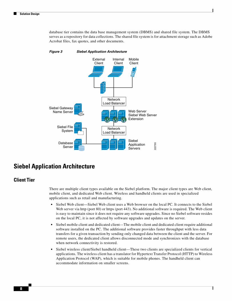
database tier contains the data base management system (DBMS) and shared file system. The DBMS serves as a repository for data collections. The shared file system is for attachment storage such as Adobe Acrobat files, fax quotes, and other documents.
Figure 3 Siebel Application Architecture
Siebel Application Architecture
Client Tier
There are multiple client types available on the Siebel platform. The major client types are Web client, mobile client, and dedicated Web client. Wireless and handheld clients are used in specialized applications such as retail and manufacturing.
• Siebel Web client—Siebel Web client uses a Web browser on the local PC. It connects to the Siebel Web server via http (port 80) or https (port 443). No additional software is required. The Web client is easy to maintain since it does not require any software upgrades. Since no Siebel software resides on the local PC, it is not affected by software upgrades and updates on the server.
• Siebel mobile client and dedicated client—The mobile client and dedicated client require additional software installed on the PC. The additional software provides faster throughput with less data transfers for a given transaction by sending only changed data between the client and the server. For remote users, the dedicated client allows disconnected mode and synchronizes with the database when network connectivity is restored.
• Siebel wireless client/Siebel handheld client—These two clients are specialized clients for vertical applications. The wireless client has a translator for Hypertext Transfer Protocol (HTTP) to Wireless Application Protocol (WAP), which is suitable for mobile phones. The handheld client can accommodate information on smaller screens.
SiebelApplicationServers
DatabaseServer
Siebel FileSystem
Siebel GatewayName Server Web Server
Siebel Web ServerExtension
MobileClient
InternalClient
ExternalClient
NetworkLoad Balancer
NetworkLoad Balancer
2227
93
8
Solution Design
Application Tier
The application tier contains two functional areas, services that terminate client connections and business logic.
The former component is called the Siebel Web Server Extension (SWSE). It is an add-on to Microsoft Internet Information Server (IIS). SWSE is responsible for handling Web requests from users. It forwards user requests to the Application Object Managers (AOM) via Siebel Internet Session API (SISNAPI) protocol. Siebel provides native server load balancing for highly-available Web servers. Third party load balancers are supported as well.
There are numerous Siebel application servers that provide different business applications. Each Siebel application component can be run on a single or multiple physical servers. Application components can be load balanced at the component level across different physical server pools. Load balancing can be configured with native Siebel load balancer or a third-party load balancer.
Database Tier
The database tier provides a repository to Siebel application data. It consist of a RDBMS and separate file system store.
• File system—The Siebel File System (SFS) is a server with a shared directory that provides CIFS access to other Siebel servers. The SFS is a shared storage area for images, reports, documents, and other data. A pointer in the database record locates the file in the SFS.
• Database Server—The database server is the main data store for the Siebel application. The Siebel application servers connect directly the database server. Oracle 10g is the database used in this deployment.
Gateway Name Server
Gateway name server is a repository for configuration information for each Siebel server. It has configuration information about the Siebel Enterprise.
9
Solution Design
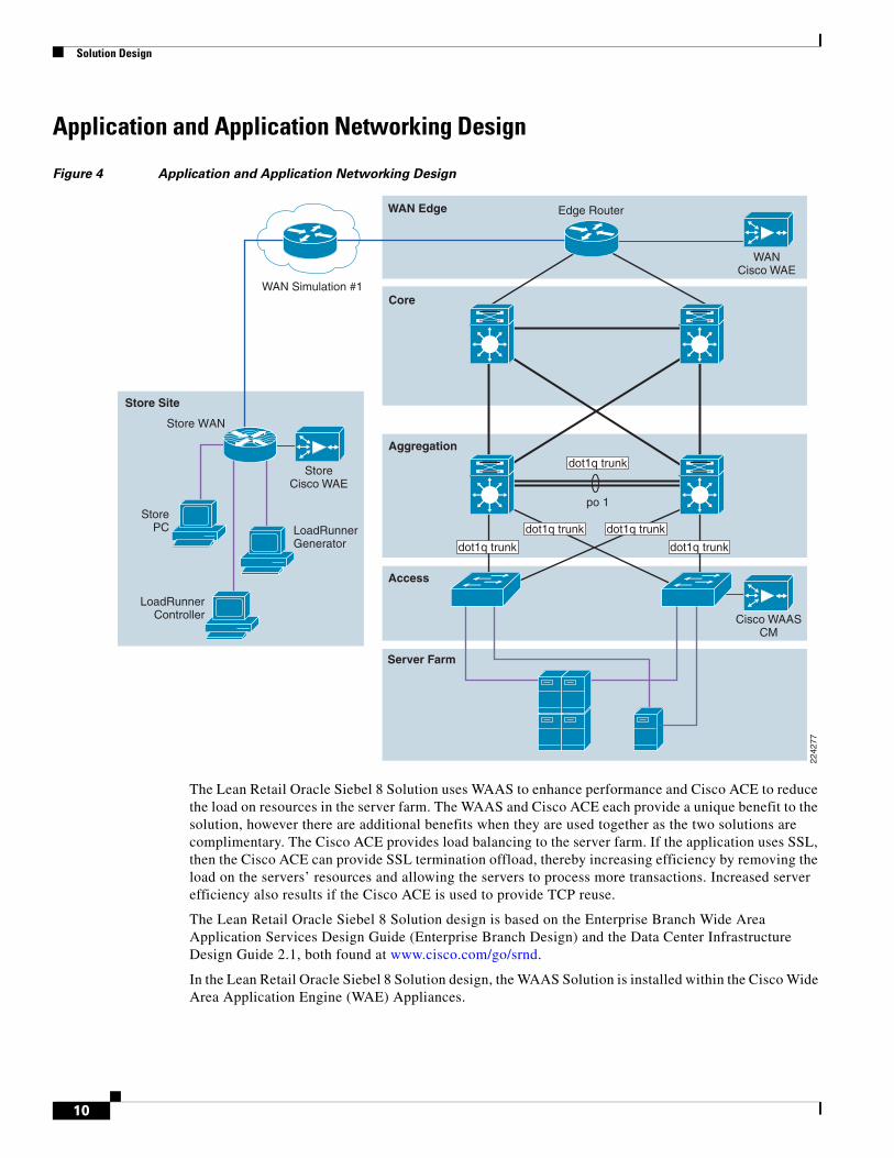
Application and Application Networking Design
Figure 4 Application and Application Networking Design
The Lean Retail Oracle Siebel 8 Solution uses WAAS to enhance performance and Cisco ACE to reduce the load on resources in the server farm. The WAAS and Cisco ACE each provide a unique benefit to the solution, however there are additional benefits when they are used together as the two solutions are complimentary. The Cisco ACE provides load balancing to the server farm. If the application uses SSL, then the Cisco ACE can provide SSL termination offload, thereby increasing efficiency by removing the load on the servers’ resources and allowing the servers to process more transactions. Increased server efficiency also results if the Cisco ACE is used to provide TCP reuse.
The Lean Retail Oracle Siebel 8 Solution design is based on the Enterprise Branch Wide Area Application Services Design Guide (Enterprise Branch Design) and the Data Center Infrastructure Design Guide 2.1, both found at www.cisco.com/go/srnd.
In the Lean Retail Oracle Siebel 8 Solution design, the WAAS Solution is installed within the Cisco Wide Area Application Engine (WAE) Appliances.
Server Farm
WAN Simulation #1
StorePC
Access
Aggregation
WAN Edge
Core
Store Site
2242
77
Edge Router
Store WAN
WANCisco WAE
LoadRunnerGenerator
LoadRunnerController
StoreCisco WAE
Cisco WAASCM
dot1q trunk
po 1
dot1q trunk
dot1q trunk dot1q trunk
dot1q trunk
10
Solution Design
Enterprise Store
The Enterprise Store Design shows the Cisco WAE appliance connected to the local store router, typically a Cisco Integrated Services Router (ISR). The design provides scalability and availability as compared to installing a Cisco WAAS Network Module within a Cisco ISR as the Cisco ISR must share its resources.
HP Mercury LoadRunner, running on a personal computer in the store, simulates users that would perform certain tasks in the application.
The traffic is redirected to the Cisco WAE via Web cache communications protocol (WCCP) from the store router. The Cisco WAE performs the following functions:
• Locally cached—If the data that is being requested is locally cached, the Cisco WAE responds to the requestor with the cached data and requests only required data from the server farm. This allows the WAN to become more efficient as only “needed data” requested.
• New data—If the data that is being forwarded to the server farm or coming from the server farm, the Cisco WAE performs compression algorithms on the data allowing for the WAN to become more efficient.
WAN Simulation
The WAN simulator provides simulations of the following WAN links:
1. WAN Type 1 (Intracontinental or T1)
a. Bandwidth - 1.544 Mbps, ESF, B8ZS, Delay - 100 mS, Loss - drop one packet in every 1000 packets (0.1%)
2. WAN Type 2 (Intercontinental)
a. Bandwidth - 512 Kbps, ESF, B8ZS, Delay - 200 mS, Loss - drop one packet in every 500 packets (0.2%)
Data Center
The data center (DC) follows the design guidelines found in the Data Center Infrastructure Design Guide 2.1, a Cisco Validated Design found at http://www.cisco.com/go/srnd. The design consists of a data center WAN router, core, aggregation, and access Ethernet switching, and the server farm where the application resides. In this document, the focus is on the DC WAN router, aggregation, and the server farm. The core Ethernet switching provides routing to and from the DC WAN router and the aggregation. The access Ethernet switching provides Layer 2 connectivity for the server farms to the aggregation.
The DC WAN router performs the same function as the store WAN router by redirecting traffic to the DC Cisco WAE. The DC Cisco WAE performs the following:
• Locally cached—If the data that is being requested is locally cached, the Cisco WAE responds to the requestor with the cached data and requests only required data from the store. This allows the WAN to become more efficient as only “needed data” is requested.
• New data—If the data that is being forwarded to the store or coming from the store, the Cisco WAE performs compression algorithms on the data allowing for the WAN to become more efficient.
Included in the data center is the Cisco WAAS central manager (CM), which runs on the Cisco WAE appliance. The Cisco WAAS CM provides a centralized mechanism for configuring Cisco WAAS features and reporting and monitoring Cisco WAAS traffic. It can manage a topology containing
11
Solution Design
thousands of Cisco WAE nodes and be accessed from any Web browser using SSL. The Cisco WAAS CM can be configured for high availability by deploying a pair of Cisco WAE appliances as central managers.
Within a Cisco WAAS topology, each Cisco WAE runs a process called central management system (CMS). The CMS process provides SSL-encrypted bidirectional configuration synchronization of the Cisco WAAS CM and the Cisco WAE appliances. The CMS process is also used to exchange reporting information and statistics at a configurable interval. When the administrator applies configuration or policy changes to a Cisco WAE appliance or a group of Cisco WAE appliances, the Cisco WAAS Central Manager automatically propagates the changes to each of the managed Cisco WAEs. Cisco WAEs that are not available to receive the changes will receive them the next time the appliances become available.
The aggregation segment contains Cisco ACE, which provides the following features:
• Virtualization—Virtualization is device partitioning into multiple contexts, where each context can be configured for different applications and is independent of any others. In the Lean Retail Oracle Siebel 8 Solution, Cisco ACE is configured with the Admin context and the Siebel context. Note that the Cisco ACE can support up to 250 contexts.
• Session persistence—Session persistence is the ability to forward client requests to the same server for the duration of the session. Siebel 8.0 requires either source Internet Protocol (IP) based session persistence or HTTP cookie based session persistence.
• Transparent interception—Transparent interception performs a Network Address Translation (NAT) function to conceal the real server IP address that is residing in the server farm. The Siebel context is configured with a Virtual IP (VIP) that provides a single address that users use to connect to the server farm. This allows users to access the Siebel application by placing a single IP in the Web browser.
• Allowed server connections—Allowed server connections is the maximum number of active connections value on a per-server basis and/or globally to the server farm.
• Health monitoring—Health monitoring is used to track the state of the server and determine its ability to process connections in the server farm. The Siebel context used a compound probe to determine if servers are operational and responding to HTTP requests.
Cisco ACE provides load balancing of the traffic to the server farm using one of the following methods: Round Robin, Weighted Round Robin, Least Connections, Hash address, Hash cookie, Hash Header, and Hash URL. In the Lean Retail Oracle Siebel 8 Solution, Least Connections was used, which selects the server with the fewest number of server connections. Cisco ACE is also used to provide SSL offload and TCP reuse.
Inter-chassis Cisco ACE redundancy was used, in which a Cisco ACE module in one Cisco Catalyst 6500 Series Switch chassis is protected by a Cisco ACE module in a peer Cisco Catalyst 6500 Series Switch chassis connected by a fault tolerant (FT) VLAN. The FT VLAN is used to transmit flow-state information, configuration synchronization information, and the redundancy heartbeat.
Server Farms
The Web server farm consisted of three Microsoft IIS Web servers with SWSE. A separate application server farm consisted of three Siebel application Servers connected to Oracle Database 10G.
The Siebel application resides on the Windows 2003 Enterprise Edition server operating system, with 3.4 GHz Intel Pentium D processors and 2 GB of RAM and 2 80 GB SATA hard drives.
Oracle Database 10G resides on the Windows 2003 Enterprise Edition server operating system with two 3.4 GHz dual core Intel Xeon processors and 3.25 GB of RAM and 2 80 GB SATA hard drives.
12
Solution Design
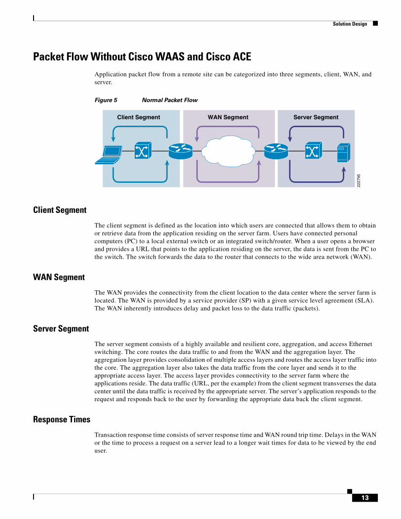
Packet Flow Without Cisco WAAS and Cisco ACEApplication packet flow from a remote site can be categorized into three segments, client, WAN, and server.
Figure 5 Normal Packet Flow
Client Segment
The client segment is defined as the location into which users are connected that allows them to obtain or retrieve data from the application residing on the server farm. Users have connected personal computers (PC) to a local external switch or an integrated switch/router. When a user opens a browser and provides a URL that points to the application residing on the server, the data is sent from the PC to the switch. The switch forwards the data to the router that connects to the wide area network (WAN).
WAN Segment
The WAN provides the connectivity from the client location to the data center where the server farm is located. The WAN is provided by a service provider (SP) with a given service level agreement (SLA). The WAN inherently introduces delay and packet loss to the data traffic (packets).
Server Segment
The server segment consists of a highly available and resilient core, aggregation, and access Ethernet switching. The core routes the data traffic to and from the WAN and the aggregation layer. The aggregation layer provides consolidation of multiple access layers and routes the access layer traffic into the core. The aggregation layer also takes the data traffic from the core layer and sends it to the appropriate access layer. The access layer provides connectivity to the server farm where the applications reside. The data traffic (URL, per the example) from the client segment transverses the data center until the data traffic is received by the appropriate server. The server’s application responds to the request and responds back to the user by forwarding the appropriate data back the client segment.
Response Times
Transaction response time consists of server response time and WAN round trip time. Delays in the WAN or the time to process a request on a server lead to a longer wait times for data to be viewed by the end user.
WAN Segment Server SegmentClient Segment
2227
95
13
Solution Design
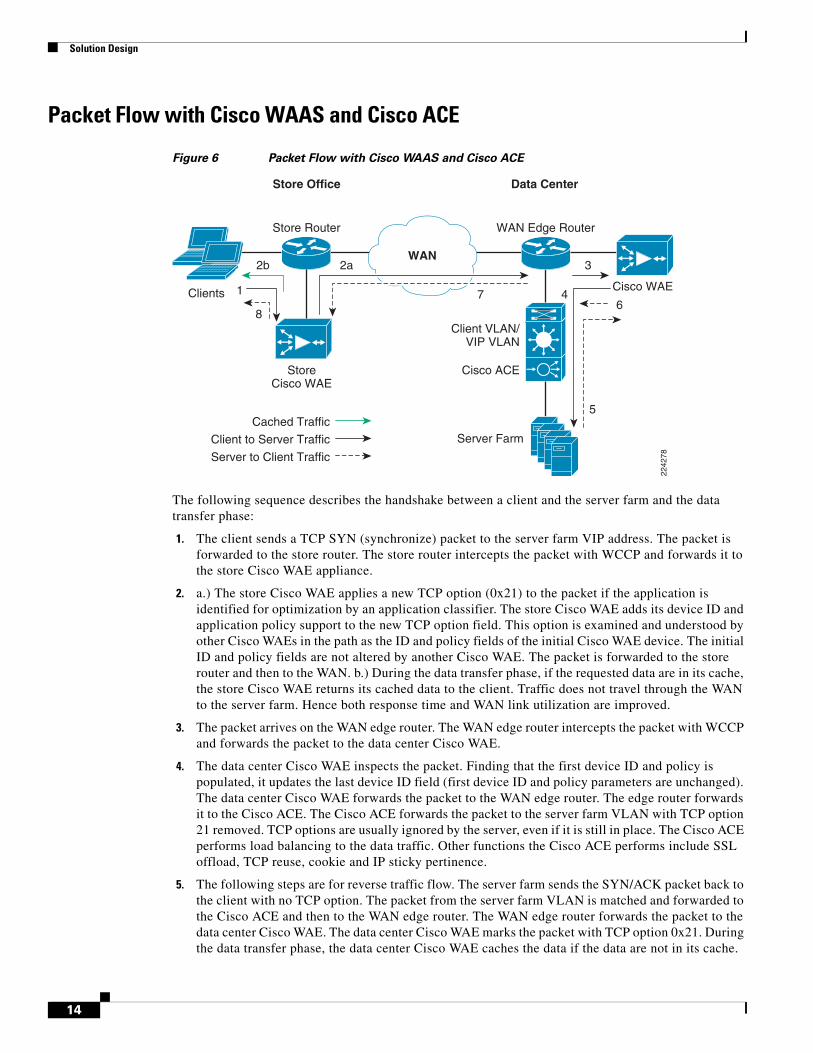
Packet Flow with Cisco WAAS and Cisco ACE
Figure 6 Packet Flow with Cisco WAAS and Cisco ACE
The following sequence describes the handshake between a client and the server farm and the data transfer phase:
1. The client sends a TCP SYN (synchronize) packet to the server farm VIP address. The packet is forwarded to the store router. The store router intercepts the packet with WCCP and forwards it to the store Cisco WAE appliance.
2. a.) The store Cisco WAE applies a new TCP option (0x21) to the packet if the application is identified for optimization by an application classifier. The store Cisco WAE adds its device ID and application policy support to the new TCP option field. This option is examined and understood by other Cisco WAEs in the path as the ID and policy fields of the initial Cisco WAE device. The initial ID and policy fields are not altered by another Cisco WAE. The packet is forwarded to the store router and then to the WAN. b.) During the data transfer phase, if the requested data are in its cache, the store Cisco WAE returns its cached data to the client. Traffic does not travel through the WAN to the server farm. Hence both response time and WAN link utilization are improved.
3. The packet arrives on the WAN edge router. The WAN edge router intercepts the packet with WCCP and forwards the packet to the data center Cisco WAE.
4. The data center Cisco WAE inspects the packet. Finding that the first device ID and policy is populated, it updates the last device ID field (first device ID and policy parameters are unchanged). The data center Cisco WAE forwards the packet to the WAN edge router. The edge router forwards it to the Cisco ACE. The Cisco ACE forwards the packet to the server farm VLAN with TCP option 21 removed. TCP options are usually ignored by the server, even if it is still in place. The Cisco ACE performs load balancing to the data traffic. Other functions the Cisco ACE performs include SSL offload, TCP reuse, cookie and IP sticky pertinence.
5. The following steps are for reverse traffic flow. The server farm sends the SYN/ACK packet back to the client with no TCP option. The packet from the server farm VLAN is matched and forwarded to the Cisco ACE and then to the WAN edge router. The WAN edge router forwards the packet to the data center Cisco WAE. The data center Cisco WAE marks the packet with TCP option 0x21. During the data transfer phase, the data center Cisco WAE caches the data if the data are not in its cache.
Data CenterStore Office
2b
1
8
2a
7 4
3
Cisco WAE
Store Router
Server Farm
Client VLAN/VIP VLAN
Cisco ACE
Cached Traffic
WAN Edge Router
2242
78
WAN
StoreCisco WAE
Client to Server Traffic
Server to Client Traffic
6
5
Clients
14
Implementing and Configuring the Cisco ACE Solution
6. The data center Cisco WAE sends the packet to the WAN edge router.
7. The packet travels through the WAN and arrives at the store router. The store router intercepts the packet and forwards it to the store Cisco WAE. The store Cisco WAE is aware of the Cisco WAE in the data center because the SYN/ACK TCP option 0x21 contains an ID and application policy. The auto-negotiation of the policy occurs as the store Cisco WAE compares its application-specific policy to that of its remote peer defined in the TCP option. At this point, the data center Cisco WAE and store Cisco WAE have determined the application optimizations to apply on this specific TCP flow. During the data transfer phase, the store Cisco WAE caches the data if the data are not in its cache.
8. The packet is forwarded to the store router and then to the client.
Implementing and Configuring the Cisco ACE Solution
Implementation
Implementation Overview
The Cisco ACE module used in this solution is deployed in a Cisco Catalyst 6509 switch in the data center aggregation layer. The Cisco ACE module is deployed in routed mode where multiple client and server side VLANs support unique IP subnets. In this deployment mode the Cisco ACE acts as the default gateway for the Web and application servers. Two Cisco ACE application contexts are used. Load balanced traffic traverses from the Web server farm to the application server farm on the same physical Cisco ACE. Cisco ACE is the only product on the market that accommodates and forwards traffic in multiple virtual contexts within the same hardware device.
What Was Implemented
Key features implemented on the Cisco ACE module to support this application are:
• Virtualization
• Server health monitoring
• Layer 7 load balancing
• Persistence based server cookie
• SSL termination
• TCP reuse
• Connection replication for stateful failover
What Was Not Implemented/Tested
The following was not implemented in this solution:
• Cisco ACE inserted cookie
• Layer 4 load balancing
• Persistence based on source IP address
15
Implementing and Configuring the Cisco ACE Solution
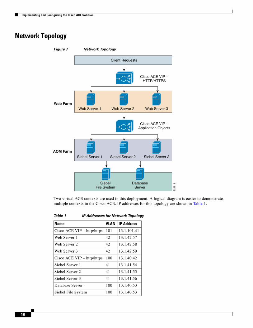
Network Topology
Figure 7 Network Topology
Two virtual ACE contexts are used in this deployment. A logical diagram is easier to demonstrate multiple contexts in the Cisco ACE. IP addresses for this topology are shown in Table 1.
Web Server 3Web Server 2
Cisco ACE VIP –HTTP/HTTPS
Cisco ACE VIP –Application Objects
Web Server 1Web Farm
AOM FarmSiebel Server 3Siebel Server 2
DatabaseServer
Client Requests
SiebelFile System
Siebel Server 1
2228
18
Table 1 IP Addresses for Network Topology
Name VLAN IP Address
Cisco ACE VIP – http/https 101 13.1.101.41
Web Server 1 42 13.1.42.57
Web Server 2 42 13.1.42.58
Web Server 3 42 13.1.42.59
Cisco ACE VIP – http/https 100 13.1.40.42
Siebel Server 1 41 13.1.41.54
Siebel Server 2 41 13.1.41.55
Siebel Server 3 41 13.1.41.56
Database Server 100 13.1.40.53
Siebel File System 100 13.1.40.53
16
Implementing and Configuring the Cisco ACE Solution
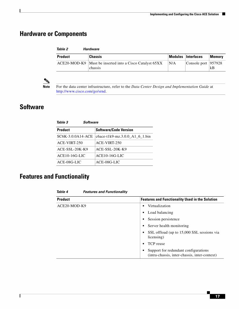
Hardware or Components
Note For the data center infrastructure, refer to the Data Center Design and Implementation Guide at http://www.cisco.com/go/srnd.
Software
Features and Functionality
Table 2 Hardware
Product Chassis Modules Interfaces Memory
ACE20-MOD-K9 Must be inserted into a Cisco Catalyst 65XX chassis
N/A Console port 957928 kB
Table 3 Software
Product Software/Code Version
SC6K-3.0.0A14-ACE c6ace-t1k9-mz.3.0.0_A1_6_1.bin
ACE-VIRT-250 ACE-VIRT-250
ACE-SSL-20K-K9 ACE-SSL-20K-K9
ACE10-16G-LIC ACE10-16G-LIC
ACE-08G-LIC ACE-08G-LIC
Table 4 Features and Functionality
Product Features and Functionality Used in the Solution
ACE20-MOD-K9 • Virtualization
• Load balancing
• Session persistence
• Server health monitoring
• SSL offload (up to 15,000 SSL sessions via licensing)
• TCP reuse
• Support for redundant configurations (intra-chassis, inter-chassis, inter-context)
17
Implementing and Configuring the Cisco ACE Solution
Features, Services, and Application Design ConsiderationsThe Siebel application architecture is flexible. Components within the multi-tiered framework can be on single or multiple servers. Traffic flow from the clients to the servers have clean boundaries between the different tiers. Figure 7 shows Cisco ACE can load balance Web servers and application object servers.
Cisco ACE Virtualization
• Contexts—Cisco ACE can be operated in a multiple contexts; up to 250 virtual contexts are supported in a single Cisco ACE. In this deployment, three contexts are used, Admin, WebFarm, and Siebel. The Admin context is the administration context for management of the Cisco ACE itself. Cisco ACE resources are assigned from the Admin context. The WebFarm and Siebel contexts are user-defined contexts. The WebFarm context hosts Web servers. The Siebel context hosts the Siebel application servers.
• Role Based Access Control (RBAC)—Cisco ACE comes with a number of system-defined roles. RBAC is used to control access to the contexts. Running show roles lists the system-defined and user-defined roles.
Server Farms and Health Probes
Server farms are groups of hosts providing similar services in the network. There are two server farms in this deployment, Web server farm and application server farms. Server health check monitors the servers within the server farm. Cisco ACE takes the server out of rotation in the event that the server is down or services are unavailable. Numerous pre-configured health probes are available on the Cisco ACE, such as http, https, ping, etc. Http probe is used to monitor both Web server farm and application server farm.
More information on health probes is available in the Cisco ACE server load-balancing configuration guide: http://www.cisco.com/en/US/docs/interfaces_modules/services_modules/ace/v3.00_A1/configuration/slb/guide/slbgd.html.
Loadbalancing/TCP Reuse/SSL Termination
Cisco ACE supports both Layer 4 and Layer 7 load balancing. Layer 7 loadbalancing is deployed in this environment. Layer 7 load balancing must be used since cookie sticky, TCP re-use, and SSL termination are enabled. TCP reuse saves server CPU resources by re-using existing TCP connections to the server.
SSL processing can take a significant amount of CPU processing cycles. Network hardware-assisted SSL termination can reduce overall server load on the Web servers. Cisco ACE supports SSL 3.0 and TLS 1.0.
Scalability and Capacity PlanningServer farms can increase application scalability and availability by load balancing applications services with multiple servers. In the event a server is down, other servers within the server farm can assume the load. Additional servers can be added to the server farm for scalability. SSL and TCP reuse can reduce additional load on the server farms.
18
Implementing and Configuring the Cisco ACE Solution
High Availability
Cisco ACE High Availability
The Cisco ACE has many high availability features. It is an active/active system. Multiple contexts can be active simultaneously on both devices in a HA configuration. When the Cisco ACE is deployed in an inter-chassis configuration, configuration and state information are preserved. Failover between the Cisco ACE is stateful. Client connections are preserved in Cisco ACE failovers.
Server Farm High Availability
High availability and scalability is achieved by load balancing multiple servers within the server farm. Multiple levels of availability are available on the Cisco ACE, such as ping probes, server farms, and backup server farms. Scalability and Capacity Planning describes individual server failures and recovery methods.
Configuration Task ListsThis section describes the steps necessary to configure the equipment.
MSFC Configuration
A Cisco ACE module interacts with clients and servers via VLANs that are set up in Cisco Catalyst 6500 Series/Cisco 7600 Series Supervisor Engine 720 (Sup 720). These VLANs must be configured on Sup720 to be allowed to be sent to the Cisco ACE module. Without this configuration, by default Cisco ACE does not receive any traffic from any VLAN.
The following sample configuration steps are performed on the MSFC. Refer to Appendix A—Cisco ACE Configuration for a complete configuration.
Step 1 Create Cisco ACE VLANs for client, server, and fault tolerant traffic:
vlan 220 name ACE-CLIENT!vlan 221 name ACE-SERVER!vlan 500 name ACE-FT-VLAN!
Step 2 Add the SVCLC configuration.
For this deployment, Cisco ACE is installed in slot 4 in the Cisco Catalyst 6500 chassis. The following configuration needs to be added to allow Cisco ACE-specific VLAN traffic to be directed towards Cisco ACE:
svclc multiple-vlan-interfacessvclc module 4 vlan-group 40svclc vlan-group 40 41-43,82,100,101
Step 3 Add the Switch Virtual Interface (SVI) configuration.
19
Implementing and Configuring the Cisco ACE Solution
The SVI (interface VLAN) configuration defines Layer 3 instance on the router MSFC. The Cisco ACE client side VLAN SVI configuration is:
WebFarminterface Vlan101 description ACE-Client vlan Web Farm ip address 13.1.101.2 255.255.255.0 standby 1 ip 13.1.101.1 standby 1 timers 1 3 standby 1 priority 115 standby 1 preempt delay minimum 1
Application Farminterface Vlan100 description DC server VLAN and AOM Farm client vlan ip address 13.1.40.2 255.255.255.0 standby 1 ip 13.1.40.1 standby 1 timers 1 3 standby 1 priority 115 standby 1 preempt delay minimum 1
WebFarm Context ConfigurationThe following steps need to run in the WebFarm context.
Remote Management Access
To access the Cisco ACE module remotely using Telnet, SSH, SNMP, HTTP, or HTTPS or to allow ICMP access to the Cisco ACE module, a policy must be defined and applied to the interface(s) the access is entering. It is recommended that only secure protocols be used to maintain compliance requirements, e.g., PCI.
The configuration steps in this section are required for both the Admin context and the application context. The following example is for the application context. Refer to Appendix A—Cisco ACE Configuration for a complete configuration.
Step 1 Configure class-map of type management:
class-map type management match-any REMOTE-MGMT 2 match protocol ssh any 3 match protocol telnet any 4 match protocol icmp any 5 match protocol http any 6 match protocol https any
Step 2 Configure policy-map of type management:
policy-map type management first-match REMOTE-ACCESS class REMOTE-MGMT permit
Step 3 Apply policy-map to the VLAN interfaces:
interface vlan 41 service-policy input REMOTE-ACCESSinterface vlan 101 service-policy input REMOTE-ACCESS
20
Implementing and Configuring the Cisco ACE Solution
Configuring Interface(s) and Default Gateway
Interface VLANs need to be configured for Layer 3 connectivity to Cisco ACE. Service policies for load balancing, security, and management access to Cisco ACE are also applied at the interface VLAN level.
The configuration steps in this section are required for both the Admin context and the application context. The following example is for the application context. Refer to Appendix A—Cisco ACE Configuration for a complete configuration.
Step 1 Define an access-list to permit/deny traffic through:
access-list ALLOW-TRAFFIC line 8 extended permit ip any anyaccess-list ALLOW-TRAFFIC line 9 extended permit icmp any any
Step 2 Configure IP address; IP address and network mask of the interface(s):
interface vlan 41 description web farm vlan ip address 13.1.41.2 255.255.255.0 alias 13.1.41.1 255.255.255.0 peer ip address 13.1.41.3 255.255.255.0
interface vlan 101 ip address 13.1.101.14 255.255.255.0 alias 13.1.101.13 255.255.255.0 peer ip address 13.1.101.15 255.255.255.0
Step 3 Apply management access policy and access-group to the interface(s), no shut of the interface(s):
interface vlan 41 access-group input ALLOW-TRAFFIC access-group output ALLOW-TRAFFIC service-policy input REMOTE-ACCESS no shutdowninterface vlan 101 access-group input ALLOW-TRAFFIC access-group output ALLOW-TRAFFIC service-policy input REMOTE-ACCESS no shutdown
Step 4 Default gateway can be configured as:
ip route 0.0.0.0 0.0.0.0 10.1.220.1
Step 5 Verify interfaces are recognized by MSFC and operational.
Type show interface and verify the VLANs are up and assigned from the supervisor.
Here is an example of a working output:
vlan220 is up Hardware type is VLAN MAC address is 00:1b:d5:9b:88:ed Virtual MAC address is 00:0b:fc:fe:1b:02 Mode : routed IP address is 10.1.220.5 netmask is 255.255.255.0 FT status is active Description:Client side vlan MTU: 1500 bytes Last cleared: never
21
Implementing and Configuring the Cisco ACE Solution
Alias IP address is 10.1.220.4 netmask is 255.255.255.0 Peer IP address is 10.1.220.6 Peer IP netmask is 255.255.255.0 Assigned from the Supervisor, up on Supervisor 53808467 unicast packets input, 17900167965 bytes 7331701 multicast, 7776 broadcast 0 input errors, 0 unknown, 0 ignored, 0 unicast RPF drops 91028995 unicast packets output, 5455629020 bytes 4 multicast, 5202 broadcast 0 output errors, 0 ignored
vlan221 is up Hardware type is VLAN MAC address is 00:1b:d5:9b:88:ed Virtual MAC address is 00:0b:fc:fe:1b:02 Mode : routed IP address is 10.1.221.2 netmask is 255.255.255.0 FT status is active Description:Server side vlan MTU: 1500 bytes Last cleared: never Alias IP address is 10.1.221.1 netmask is 255.255.255.0 Peer IP address is 10.1.221.3 Peer IP netmask is 255.255.255.0 Assigned from the Supervisor, up on Supervisor 83222640 unicast packets input, 95861661879 bytes 1118208 multicast, 47974 broadcast 0 input errors, 0 unknown, 0 ignored, 0 unicast RPF drops 53089290 unicast packets output, 4304456323 bytes 4 multicast, 14950 broadcast 0 output errors, 0 ignored
Probes
Cisco ACE uses probe, one of the available keep-alive methods, to verify the availability of a real server. Probe is configured by defining its type and name.
There are different types of probes that can be configured on Cisco ACE:
dns Configure dns probe echo Configure echo probe finger Configure finger probe ftp Configure ftp probe http Configure http probe https Configure https probe icmp Configure icmp probe imap Configure imap probe ldap Configure ldap probe pop Configure pop probe radius Configure radius probe scripted Configure script probe smtp Configure smtp probe tcp Configure tcp probe telnet Configure telnet probe udp Configure udp probe
HTTP probe is used to check the availability of the Web farm.
probe http http-probe interval 30 expect status 200 200
22
Implementing and Configuring the Cisco ACE Solution
Note The above configuration uses the default request method GET and default URI /.
Real Server
Cisco ACE selects the real server and sends traffic based on certain sets of criteria. When configuring a real server, be aware that real server name is case sensitive. The minimum configuration needed for rserver configuration is IP address and making the rserver inservice. Same rserver can be used in multiple server farms (shown later in the document). If an rserver is made no inservice at the rserver level, then it is taken out of rotation from every server farm at which it is configured. This provides the flexibility to take a server completely out of rotation with a single command.
rserver host websrvr1 description Siebel web server ip address 13.1.41.57 inservicerserver host websrvr2 description Siebel web server ip address 13.1.41.58 inservicerserver host websrvr3 description Siebel web server ip address 13.1.41.59 inservice
Server Farm
A server farm is a logical collection of real servers (rservers) that load balancer selects based on certain sets of criteria. As with real server, serverfarm name is also case sensitive.
Basic server farm configuration includes adding rservers and probes to the server farm.
serverfarm host WEBFARM probe http-probe rserver websrvr1 80 inservice rserver websrvr2 80 inservice rserver websrvr3 80 inservice
Layer 7 Load Balancing
Cisco ACE uses class-map, policy-map, and service-policy to classify and enforce a Layer 7 policy. Cisco ACE uses additional information, such as URL, HTTP header, or cookie to make a load balancing decision. The following example shows the configuration steps for URL-based matching:
Step 1 Configure Class-map of type HTTP:
class-map type http loadbalance match-any L7_WEB 2 match http url .*.
Step 2 Configure HTTP parameters (optional):
parameter-map type http HTTP_PARAMETERS server-conn reuse case-insensitive
23
Implementing and Configuring the Cisco ACE Solution
Step 3 Configure virtual IP address (VIP) using class-map of type match-all:
class-map match-all L4_WEB_VIP_CLASS
Step 4 Configure policy-map of type loadbalance to associate server farm:
policy-map type loadbalance first-match L7-WEB-MATCH class L7_WEB sticky-serverfarm sn_cookie
Step 5 Configure policy-map multimatch to associate to the first-match above:
policy-map multi-match L4-WEB-VIP class L4_WEB_VIP_CLASS loadbalance vip inservice loadbalance policy L7-WEB-MATCH loadbalance vip icmp-reply loadbalance vip advertise active
Step 6 Apply policy-map to the interface VLAN:
interface vlan 101 service-policy input L4-WEB-VIP
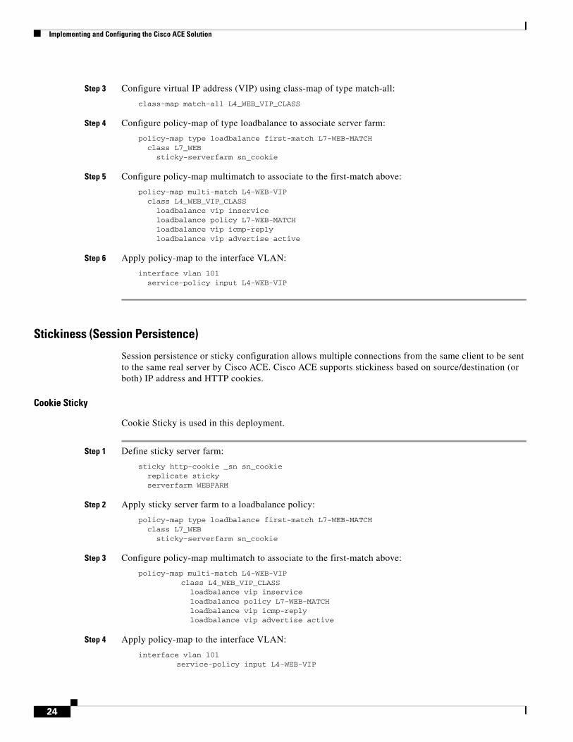
Stickiness (Session Persistence)
Session persistence or sticky configuration allows multiple connections from the same client to be sent to the same real server by Cisco ACE. Cisco ACE supports stickiness based on source/destination (or both) IP address and HTTP cookies.
Cookie Sticky
Cookie Sticky is used in this deployment.
Step 1 Define sticky server farm:
sticky http-cookie _sn sn_cookie replicate sticky serverfarm WEBFARM
Step 2 Apply sticky server farm to a loadbalance policy:
policy-map type loadbalance first-match L7-WEB-MATCH class L7_WEB sticky-serverfarm sn_cookie
Step 3 Configure policy-map multimatch to associate to the first-match above:
policy-map multi-match L4-WEB-VIP class L4_WEB_VIP_CLASS loadbalance vip inservice loadbalance policy L7-WEB-MATCH loadbalance vip icmp-reply loadbalance vip advertise active
Step 4 Apply policy-map to the interface VLAN:
interface vlan 101 service-policy input L4-WEB-VIP
24
Implementing and Configuring the Cisco ACE Solution
SSL Termination
SSL termination configuration on Cisco ACE provides SSL traffic termination on Cisco ACE instead of on the servers. This allows the offloading of server resources and also provides HTTP request inspection for various load balancing functionality.
With SSL termination on the Cisco ACE, client to Cisco ACE traffic is SSL encrypted, but Cisco ACE to server traffic is clear-text. The configuration steps to implement front end SSL termination are:
Step 1 Generate key:
crypto generate key 1024 siebelweb.keyEDAL-AGG1-ACE/WebFarm# sh crypto key allFilename Bit Size Type-------- -------- ----siebelweb.key 1024 RSA
Step 2 Define CSR parameters set:
crypto csr-params testparms country US state California locality San Jose organization-name ESE organization-unit ESE common-name www.testsiebel.com serial-number cisco123
Step 3 Generate csr:
crypto generate csr testparms siebelweb.key
-----BEGIN CERTIFICATE REQUEST-----MIIBrjCCARcCAQAwbjELMAkGA1UEBhMCVVMxEzARBgNVBAgTCkNhbGlmb3JuaWExETAPBgNVBAcTCFNhbiBKb3NlMQwwCgYDVQQKEwNFU0UxDDAKBgNVBAsTA0VTRTEbMBkGA1UEAxMSd3d3LnRlc3RzaWViZWwuY29tMIGfMA0GCSqGSIb3DQEBAQUAA4GNADCBiQKBgQDE02KxO5XSi6FqwUCJ4py58NTfTiGDu/MczEt6ejVCVnLmRdakPXQovjy3ALatZe6p7IqjBDvoPSU/no6g2nAKqqObkwkmNCTep6rwNwBSlyXoh9lVvwZIFhWYmDgV5jYInPRT5qHmv5RXJK9YiMwhcQOSqJzCgF+L5RZP8aUUOQIDAQABoAAwDQYJKoZIhvcNAQEEBQADgYEARr1CUrhloKmhRtAtBeDuRmb4w6QOymrg6m8vwJ0Sywc03F4BBoFqfPmSACrSW/qyfjGYLK0dYbZV0xq+min2932zN2e6lVAdHtuFLt0/ACKOTAtGFXe849WoEghuKvICV/RZslNXgNAO4/udL6p7vQ02+sSFqLQ9OQ0fWX2nwo8=-----END CERTIFICATE REQUEST-----
Step 4 Obtain certificate:
An SSL certificate can be obtained from various Certificate Authority (CA) companies like VERISIGN. A local certificate server was used to generate the certificate.
Step 5 Import the key from the certificate server:
EDAL-AGG1-ACE/Siebel# crypto import ftp 13.1.40.53 anonymous siebelweb.cer siebelweb.cerPassive mode on.Hash mark printing on (1024 bytes/hash mark).#Successfully imported file from remote server.
25
Implementing and Configuring the Cisco ACE Solution
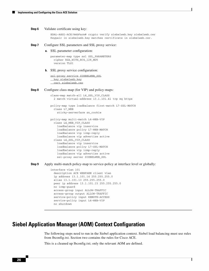
Step 6 Validate certificate using key:
EDAL-AGG1-ACE/WebFarm# crypto verify siebelweb.key siebelweb.cerKeypair in siebelweb.key matches certificate in siebelweb.cer.
Step 7 Configure SSL parameters and SSL proxy service:
a. SSL parameter configuration:
parameter-map type ssl SSL_PARAMETERS cipher RSA_WITH_RC4_128_MD5 version TLS1
b. SSL proxy service configuration:
ssl-proxy service SIEBELWEB_SSL key siebelweb.key cert siebelweb.cer
Step 8 Configure class-map (for VIP) and policy-maps:
class-map match-all L4_SSL_VIP_CLASS 2 match virtual-address 13.1.101.41 tcp eq https
policy-map type loadbalance first-match L7-SSL-MATCH class L7_WEB sticky-serverfarm sn_cookie
policy-map multi-match L4-WEB-VIP class L4_WEB_VIP_CLASS loadbalance vip inservice loadbalance policy L7-WEB-MATCH loadbalance vip icmp-reply loadbalance vip advertise active class L4_SSL_VIP_CLASS loadbalance vip inservice loadbalance policy L7-SSL-MATCH loadbalance vip icmp-reply loadbalance vip advertise active ssl-proxy server SIEBELWEB_SSL
Step 9 Apply multi-match policy-map to service-policy at interface level or globally:
interface vlan 101 description ACE WEBFARM client vlan ip address 13.1.101.14 255.255.255.0 alias 13.1.101.13 255.255.255.0 peer ip address 13.1.101.15 255.255.255.0 no icmp-guard access-group input ALLOW-TRAFFIC access-group output ALLOW-TRAFFIC service-policy input REMOTE-ACCESS service-policy input L4-WEB-VIP no shutdown
Siebel Application Manager (AOM) Context ConfigurationThe following steps need to run in the Siebel application context. Siebel load balancing must use rules from lbconfig.txt. Section two contains the rules for Cisco ACE.
This is a cleaned up lbconfig.txt; only the relevant AOM are defined.
26
Implementing and Configuring the Cisco ACE Solution
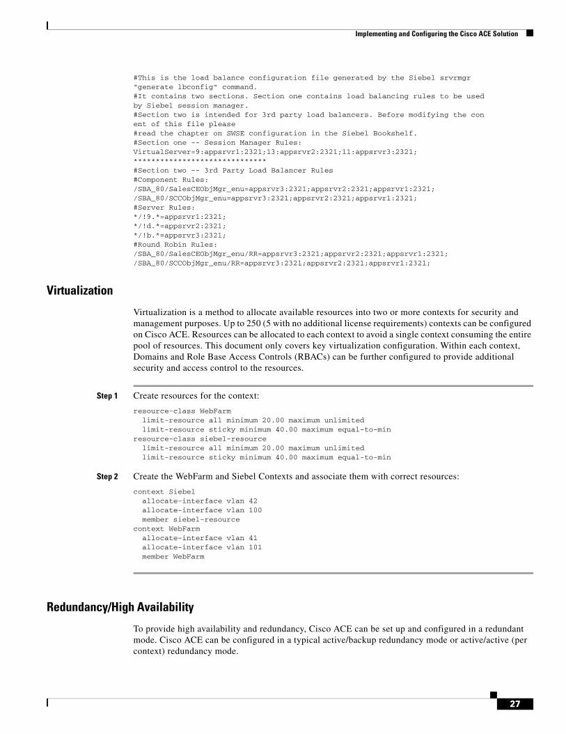
#This is the load balance configuration file generated by the Siebel srvrmgr"generate lbconfig" command.#It contains two sections. Section one contains load balancing rules to be usedby Siebel session manager.#Section two is intended for 3rd party load balancers. Before modifying the conent of this file please#read the chapter on SWSE configuration in the Siebel Bookshelf.#Section one -- Session Manager Rules:VirtualServer=9:appsrvr1:2321;13:appsrvr2:2321;11:appsrvr3:2321;******************************#Section two -- 3rd Party Load Balancer Rules#Component Rules:/SBA_80/SalesCEObjMgr_enu=appsrvr3:2321;appsrvr2:2321;appsrvr1:2321;/SBA_80/SCCObjMgr_enu=appsrvr3:2321;appsrvr2:2321;appsrvr1:2321;#Server Rules:*/!9.*=appsrvr1:2321;*/!d.*=appsrvr2:2321;*/!b.*=appsrvr3:2321;#Round Robin Rules:/SBA_80/SalesCEObjMgr_enu/RR=appsrvr3:2321;appsrvr2:2321;appsrvr1:2321;/SBA_80/SCCObjMgr_enu/RR=appsrvr3:2321;appsrvr2:2321;appsrvr1:2321;
Virtualization
Virtualization is a method to allocate available resources into two or more contexts for security and management purposes. Up to 250 (5 with no additional license requirements) contexts can be configured on Cisco ACE. Resources can be allocated to each context to avoid a single context consuming the entire pool of resources. This document only covers key virtualization configuration. Within each context, Domains and Role Base Access Controls (RBACs) can be further configured to provide additional security and access control to the resources.
Step 1 Create resources for the context:
resource-class WebFarm limit-resource all minimum 20.00 maximum unlimited limit-resource sticky minimum 40.00 maximum equal-to-minresource-class siebel-resource limit-resource all minimum 20.00 maximum unlimited limit-resource sticky minimum 40.00 maximum equal-to-min
Step 2 Create the WebFarm and Siebel Contexts and associate them with correct resources:
context Siebel allocate-interface vlan 42 allocate-interface vlan 100 member siebel-resourcecontext WebFarm allocate-interface vlan 41 allocate-interface vlan 101 member WebFarm
Redundancy/High Availability
To provide high availability and redundancy, Cisco ACE can be set up and configured in a redundant mode. Cisco ACE can be configured in a typical active/backup redundancy mode or active/active (per context) redundancy mode.
27
Implementing and Configuring the Cisco ACE Solution
! Configure FT interfaceft interface vlan 43 ip address 192.168.100.1 255.255.255.0 peer ip address 192.168.100.2 255.255.255.0 no shutdown! Configure FT peerft peer 1 heartbeat interval 200 heartbeat count 20 ft-interface vlan 43! Create a fault tolerant group - one for each contextft group 1 peer 1 priority 120 associate-context Siebel inserviceft group 2 peer 1 priority 120 associate-context WebFarm inservice
By assigning context(s) to an FT group, a network administrator can create multiple groups for multiple contexts where the ACTIVE contexts can be distributed among the two Cisco ACE modules. This setup provides active/active redundancy setup for load sharing and high availability.
Management Access Configuration
Refer to the step-by-step instructions in WebFarm Context Configuration. The access and permission list is the same. This is the interface configuration with different IP addresses:
interface vlan 42 description application farm vlan ip address 13.1.42.2 255.255.255.0 alias 13.1.42.1 255.255.255.0 peer ip address 13.1.42.3 255.255.255.0 no icmp-guard access-group input ALLOW-TRAFFIC service-policy input REMOTE-ACCESS no shutdowninterface vlan 100 description ACE AOM client vlan ip address 13.1.40.11 255.255.255.0 alias 13.1.40.10 255.255.255.0 peer ip address 13.1.40.12 255.255.255.0 no icmp-guard access-group input ALLOW-TRAFFIC service-policy input REMOTE-ACCESS service-policy input L4-APPS-VIP no shutdown
Configuring Interface(s) and Default Gateway
Refer to the step-by-step instructions in WebFarm Context Configuration. This is the configuration:
ip route 0.0.0.0 0.0.0.0 13.1.40.1
28
Implementing and Configuring the Cisco ACE Solution
Probes
Refer to the step-by-step instructions in WebFarm Context Configuration.
HTTP probe is used to check the availability of the application farm. It checks port 2321 of the Siebel Servers.
probe http scbroker-probe port 2321 interval 30 passdetect interval 10 passdetect count 1 request method get url /SBA_80/scbroker expect status 100 200
Real Server
Cisco ACE selects the real server and sends traffic based on certain sets of criteria. When configuring a real server, be aware that real server name is case sensitive. The minimum configuration needed for rserver configuration is IP address and making the rserver inservice. The same rserver can be used in multiple server farms (shown later in the document). If an rserver is made no inservice at the rserver level, then it is taken out of rotation from every server farm at which it is configured. This provides the flexibility to take a server completely out of rotation with a single command.
rserver host appsrvr1 description Siebel application server ip address 13.1.42.54 inservicerserver host appsrvr2 description Siebel application server ip address 13.1.42.55 inservicerserver host appsrvr3 description Siebel application server ip address 13.1.42.56 inservice inservice
Server Farms
A server farm is a logical collection of real servers (rservers) that load balancer can select based on certain sets of criteria. As with real server, serverfarm name is also case sensitive.
The Siebel application requires Layer 7 load balancing for the AOM. Each application must be defined as its own server farm. Each server must also be defined as a server farm for direct server access. The total number of server farms is two times the number of AOMs plus the number of servers. In this case, seven server farms must be defined for two applications
Step 1 Define each server as serverfarm for direct server mapping.
serverfarm host APPS1FARM probe scbroker-probe rserver appsrvr1 2321 inserviceserverfarm host APPS2FARM probe scbroker-probe rserver appsrvr2 2321 inserviceserverfarm host APPS3FARM rserver appsrvr3 2321
29
Implementing and Configuring the Cisco ACE Solution
inservice
Step 2 Define the CallCenter application server farm. RR is the reconnect request server farm. Retry requests are forward to the RR server farm is the initial request is rejected.
serverfarm host SCCOBJMGR_FARM probe scbroker-probe rserver appsrvr1 2321 inservice rserver appsrvr2 2321 inservice rserver appsrvr3 2321 inserviceserverfarm host SCCOBJMGR_FARM_RR probe scbroker-probe rserver appsrvr1 2321 inservice rserver appsrvr2 2321 inservice rserver appsrvr3 2321 inservice
Step 3 Define the eSales application server farm. RR is the reconnect request server farm. Retry requests are forward to the RR server farm is the initial request is rejected.
serverfarm host SALESCEOBJMGR_FARM probe scbroker-probe rserver appsrvr2 2321 inservice rserver appsrvr3 2321 inserviceserverfarm host SALESCEOBJMGR_FARM_RR rserver appsrvr2 2321 inservice rserver appsrvr3 2321 inservice
Layer 7 Load Balancing
Cisco ACE uses class-map, policy-map, and service-policy to classify and enforce a Layer 7 policy. Cisco ACE uses additional information such as URL, HTTP header, or cookie to make a load balancing decision. The following example shows the configuration steps for URL-based matching.
The following example shows the configuration steps needed:
Step 1 Configure Class-map of type HTTP for the different application component and server requests:
class-map type http loadbalance match-any L7_APPSERVER_1_CLASS 2 match http url .*/!9\. method POSTclass-map type http loadbalance match-any L7_APPSERVER_2_CLASS 2 match http url .*/!d\. method POSTclass-map type http loadbalance match-any L7_APPSERVER_3_CLASS 2 match http url .*/!b\. method POSTclass-map type http loadbalance match-any L7_SALESCEOBJMGR_CLASS 2 match http url .*/sba_80/sseobjmgr_enu method POSTclass-map type http loadbalance match-any L7_SALESCEOBJMGR_RR_CLASS 2 match http url .*/sba_80/sseobjmgr_enu/rr method POSTclass-map type http loadbalance match-any L7_SCCOBJMGR_CLASS 2 match http url .*/sba_80/sccobjmgr_enu method POST
30
Implementing and Configuring the Cisco ACE Solution
class-map type http loadbalance match-any L7_SCCOBJMGR_RR_CLASS 2 match http url .*/sba_80/sccobjmgr_enu/rr method POST
Step 2 Configure connection parameter, which sets the connection timeout for idle sessions:
parameter-map type connection TCP_PARAMETER set timeout inactivity 86400
Step 3 Configure virtual IP Address (VIP) using class-map of type match-all:
class-map match-all L4_APPS_VIP_CLASS-2321 2 match virtual-address 13.1.40.42 tcp eq 2321
Step 4 Configure policy-map of type loadbalance to associate server farm. Each of the class mapS is associated with a specific server farm:
policy-map type loadbalance first-match L7-APPS-MATCH class L7_SCCOBJMGR_CLASS serverfarm SCCOBJMGR_FARM class L7_APPSERVER_1_CLASS serverfarm APPS1FARM class L7_APPSERVER_2_CLASS serverfarm APPS2FARM class L7_APPSERVER_3_CLASS serverfarm APPS3FARM class L7_SALESCEOBJMGR_CLASS serverfarm SALESCEOBJMGR_FARM class L7_SCCOBJMGR_RR_CLASS serverfarm SCCOBJMGR_FARM_RR class L7_SALESCEOBJMGR_RR_CLASS serverfarm SALESCEOBJMGR_FARM_RR
Step 5 Configure policy-map multimatch to associate to the first-match above:
policy-map multi-match L4-APPS-VIP class L4_APPS_VIP_CLASS-2321 loadbalance vip inservice loadbalance policy L7-APPS-MATCH loadbalance vip icmp-reply loadbalance vip advertise active connection advanced-options TCP_PARAMETER
Step 6 Apply policy-map to the interface VLAN:
interface vlan 100 description ACE AOM client vlan ip address 13.1.40.11 255.255.255.0 alias 13.1.40.10 255.255.255.0 peer ip address 13.1.40.12 255.255.255.0 no icmp-guard access-group input ALLOW-TRAFFIC service-policy input REMOTE-ACCESS service-policy input L4-APPS-VIP no shutdown
Configuration and MenusSee Appendix A—Cisco ACE Configuration.
31
Implementing and Configuring the Cisco WAAS Solution
Troubleshooting ConfigurationThese show commands can help troubleshoot issues with the configuration:
• show stats—Displays the statistical information relating to the operation of the Cisco ACE.
• show service-policy policy_name—Displays the statistics for service policies enabled globally within a context or on a specific interface.
• show serverfarm name detail—Displays the summary or detailed server-farm statistics.
• show rserver rserver_name detail—Displays the summary or detailed statistics for a named real server or for all real servers.
• show probe—Displays the probe information including script probes.
• show arp—Displays the current active IP address-to-MAC address mapping in the ARP table, statistics, or inspection or timeout configuration.
• show arp statistics—Displays the ARP statistics for all VLAN interfaces.
• show context—Verifies the auto-sync configuration of all contexts.
• show ft group status—Verifies FT status of all configured context in the Cisco ACE.
• show ft peer detail—Verifies the state of FT peering.
• show resource usage—Displays the resource usage for each context.
• show np NP_number—Displays the hardware information stored on the three network processors.
Implementing and Configuring the Cisco WAAS Solution
Implementation
Implementation Overview
The Cisco WAAS solution requires a minimum of three Cisco Wide Area Application Engine (WAE) appliances to auto-discover and deliver applicable application optimizations. One Cisco WAE is placed in the enterprise data center and the other at the store site. The enterprise data center Cisco WAE is placed on the WAN edge connected to the WAN router. The third Cisco WAE is used for the Central Manager. The design offloads the Cisco WAE device from the local store router and leverages the available ports on a local switch. This design provides scalability and availability for the solution.
What Was Implemented
Cisco WAAS technology requires the efficient and predictable interception of application traffic to produce results. It is critical that the Cisco WAE device see the entire TCP conversation. At the WAN edge, Cisco routers support the following four methods of traffic interception:
• Policy-based routing (PBR)
• Web Cache Communications Protocol (WCCP) v2
• Service policy with Cisco ACE
• Inline hardware
32
Implementing and Configuring the Cisco WAAS Solution
WCCPv2 is the most common method used in the store environment; therefore, WCCPv2 has been leveraged for this solution.
Note Cisco WAEs “out of box” have a standard set of application variables and ports that are defined for optimization. In this solution no changes need to be made to the standard default configuration of the Cisco WAEs.
What Was Not Implemented
The following was not implemented in this solution:
• Cisco WAAS Network Module in which Cisco WAAS is installed in an integrated services router, providing a comprehensive solution within a single platform. This design provides less scalability and should be considered for use with a store with a small number of users.
Network Topology
Figure 8 Network Topology
WAN Simulation #1
StorePC
Access
Aggregation
WAN Edge
Core
Store Site
2242
79
Edge Router
Store WAN
WANCisco WAE
LoadRunnerGenerator
LoadRunnerController
StoreCisco WAE
Cisco WAASCM
dot1q trunk
po 1
dot1q trunk
dot1q trunk dot1q trunk
dot1q trunk
33
Implementing and Configuring the Cisco WAAS Solution
Hardware or Components
Software
Features and Functionality
Features, Services, and Application Design ConsiderationsMost multi-tiered applications support Web-based clients in addition to native application clients. Web-based clients use port 80 to communicate to the Web server. Applications in this test use port 80. In the context of Cisco WAAS, port 80 is accelerated by default; no further configuration in the Cisco WAE is necessary unless the application requires ports that are not part of the default application profile. For applications that use TCP ports that are not defined in the default application profile, you must define ports to the existing application profile or create a new application profile with the associated ports. With the recommended design of Cisco WAAS at the WAN edge, client data only traverse the Cisco WAEs once, at the ingress/egress of the data center. Further application communication between the Web servers, application servers, and database servers are within the data center and are not affected by Cisco WAAS.
Transport Flow Optimization (TFO), Data Redundancy Elimination (DRE), and Lempel-Ziv (LZ)-compression, the three key technologies of Cisco WAAS, are enabled by default. Each of these features and functions are described in Features and Functionality. The net results are reduced traffic and
Table 5 Hardware
Product Chassis Modules Interfaces Memory
WAE-7326-K9 WAE-7326-K9 N/A 2 10/100/1000 Ethernet, serial port
4 Gbytes, 144 GB SCSI HD
WAE-612-K9 WAE-612-K9 N/A 2 10/100/1000 Ethernet, serial port
2 Gbytes, 144 GB SCSI HD
Table 6 Software
Product Software/Code Version
SF-WAAS-4.0-SC-K9 4.0.13
WAAS-ENT-APL Cisco WAAS Enterprise License for 1 Cisco WAE Appliance
SF-WAAS-4.0-SC-K9 4.0.13
WAAS-ENT-APL Cisco WAAS Enterprise License for 1 Cisco WAE Appliance
Table 7 Features and Functionality
Product Supported Features and Functionality Used in the Solution
WAE-7326-K9, WAE-612-K9 Transport Flow Optimization (TFO)
Data Redundancy Elimination (DRE), LZ compression
34
Implementing and Configuring the Cisco WAAS Solution
decreased latency across the WAN. Since Cisco WAAS deployments are transparent to the network and application, applications do not need to be aware of the added functions and continue to work as-is, but with decreased response time and increased traffic throughput and transactions.
Additional information on Cisco WAAS data center and branch designs are available at:
• Enterprise Data Center Wide Area Application Services (WAAS) Design Guide http://www.cisco.com/application/pdf/en/us/guest/netsol/ns377/c649/ccmigration_09186a008081c7da.pdf
• Enterprise Branch Wide Area Application Services Design Guide (Version 1.1) http://www.cisco.com/application/pdf/en/us/guest/netsol/ns477/c649/ccmigration_09186a008081c7d5.pdf
Scalability and Capacity PlanningCisco WAE farms can scale up to 32 devices with WCCP and up to 16000 with Cisco ACE load balancing. Cisco WAAS services scale linearly in a N+1 configuration. In addition to the Max Optimized TCP connections, the fan out ratio between the DC Cisco WAE and store Cisco WAE have to be considered. The fan out ratio is determined by a number of factors, such as the number of Cisco WAEs in the store offices, amount of network traffic, and number of TCP connections. A sizing tool is available internally that can help automate sizing decisions. NetFlow, NetQoS, and other network analysis tools can provide additional traffic flow information for increased accuracy in scalability and capacity planning.
Table 8 Cisco WAE Family Performance and Scalability
Device
Max Optimized TCP Connections
Max CIFS Sessions
Single Drive Capacity [GB]
Max Drives RAM [GB]
Max Recommended WAN Link [Mbps]
Max Optimized Throughput [Mbps]
Max Core Fan-out [Peers]
CM Scalability [Devices]
NME-WAE-302
250 N/A 80 1 0.5 4 90
NME-WAE-502
500 500 120 1 1 4 150
WAE-512-1GB
750 750 250 2 1 8 100 5 500
WAE-512-2GB
1500 1500 250 2 2 20 150 10 1000
WAE-612-2GB
2000 2000 300 2 2 45 250 30 2000
WAE-612-4GB
6000 2500 300 2 4 90 350 50 2500
WAE-7326 7500 2500 300 6 4 155 450 96
WAE-7341 12000 12000 300 4 12 310 800 200
WAE-7371 50000 32000 300 6 24 1000 1500 400
35
Implementing and Configuring the Cisco WAAS Solution
Store devices range from the NME-WAE-302 for very small offices to the 612-4GB or even higher models for bigger store sites. WAE 7326 and up are designed for data center installations.
High AvailabilityCisco WAAS deployments are transparent to the application. The application client and server do not know Cisco WAAS is optimizing traffic flows. High availability is built into the WCCP interception. When WCCP is not active or if Cisco WAAS devices are not functioning, WCCP does not forward traffic to the Cisco WAEs, resulting in un-optimized traffic flow. This is the worse case scenario; traffic flow continues but is not optimized.
Device High Availability
The Cisco WAEs have many built-in high availability features. The disk subsystem is recommended to be configured with RAID 1 protection. RAID 1 is mandatory when two or more drives are installed in the Cisco WAE. With RAID 1, failure of the physical drive does not affect normal operations. Failed disks can be replaced during planned downtime. Multiple network interfaces are available. Standby interfaces can be configured for interface failover. A standby interface group guards against network interface failure on the Cisco WAE and switch. When connected to separate switches in active/standby mode, the standby interface protects the Cisco WAE from switch failure.
N+1 Availability
Cisco WAEs and the network provide additional high availability (HA) capabilities. Routers can be configured redundantly providing HSRP or GLBP services. Cisco WAEs can configured in a N+1 configuration. N+1 configuration provides scalability and availability. This design calls for N number of Cisco WAEs for a specific workload, then add a standby Cisco WAE. Since the workload always distributes evenly among the Cisco WAEs, the standby Cisco WAE is utilized, reducing overall workload. In the event that a Cisco WAE fails, the rest of Cisco WAEs can resume normal workload.
Configuration Task ListsThe following subsections describe the information required prior to configuration of the equipment.
Central Manager
Central Manager (CM) is the management component of Cisco WAAS. CM provides a GUI for configuration, monitoring, and management of multiple store and data center Cisco WAEs. CM can scale to support thousands of Cisco WAE devices for large-scale deployments. The CM is necessary for making any configuration changes via the Web interface. In the event of CM failure, Cisco WAEs continue to function, however changes cannot be made using the Web pages on the CM until the CM comes back online.
Cisco WAEs need to connect to the CM on the initial setup. The registration process adds the Cisco WAE to the CM and initializes the local Cisco WAE data base. When disk encryption on the Cisco WAE is enabled, the CM must be available to distribute the encryption key in the event the Cisco WAE reboots.
36
Implementing and Configuring the Cisco WAAS Solution
Centralized reporting can be obtained from the CM. Individually, the Cisco WAEs provide basic statistics via the CLI and local device GUI. System-wide application statistics are available from the CM GUI. Detailed reports such as total traffic reduction, application mix, and pass-through traffic can be obtained from CM GUI.
The following example shows the configuration steps needed to configure CM.
Note At least one Cisco WAE must be the Central Manager. Adding backup Central Managers increases availability. Central Managers should be installed in the data center with other critical servers, not in the store or data center WAN-facing segments.
Step 1 Configure the device to be Central Manager. It is set to application-accelerator mode by default:
device mode central-manager
Step 2 Configure the Central Manager IP address:
interface GigabitEthernet 1/0ip address 13.1.40.8 255.255.255.0
Step 3 Set up the default gateway:
ip default-gateway 13.1.40.1
Step 4 Set the primary interface. Cisco WAAS supports multiple network interfaces type, port channels, and standby interface. Cisco WAAS uses the primary interface for traffic interception and delivery. The primary interface must defined:
primary-interface GigabitEthernet 1/0
Step 5 Define the NTP server. Traffic statistics are captured and forward to Central Manager and NetQos. The time stamp on each packet needs to be accurate. All Cisco WAEs and routers should synchronize to the same NTP server:
ntp server 13.1.5.2
Step 6 Initialize the Configuration Management System (CMS) database. The CMS contains configuration rules and information. The Central Manager is the repository of CMS data:
cms enable
Step 7 Login to the CM Web GUI on port 8443 after the CM is up and running. The initial CM screen is an overview of the health of the system. It contains information on number of devices, status, application traffic, and optimization rate.
37
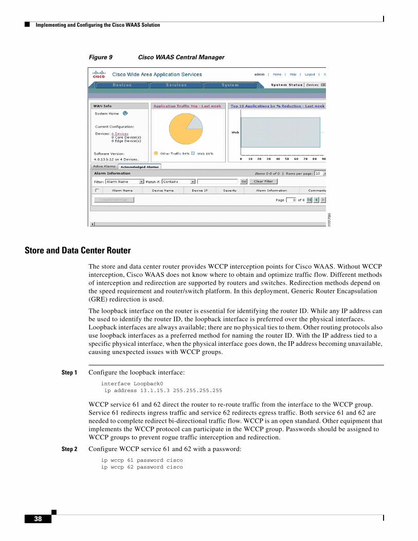
Implementing and Configuring the Cisco WAAS Solution
Figure 9 Cisco WAAS Central Manager
Store and Data Center Router
The store and data center router provides WCCP interception points for Cisco WAAS. Without WCCP interception, Cisco WAAS does not know where to obtain and optimize traffic flow. Different methods of interception and redirection are supported by routers and switches. Redirection methods depend on the speed requirement and router/switch platform. In this deployment, Generic Router Encapsulation (GRE) redirection is used.
The loopback interface on the router is essential for identifying the router ID. While any IP address can be used to identify the router ID, the loopback interface is preferred over the physical interfaces. Loopback interfaces are always available; there are no physical ties to them. Other routing protocols also use loopback interfaces as a preferred method for naming the router ID. With the IP address tied to a specific physical interface, when the physical interface goes down, the IP address becoming unavailable, causing unexpected issues with WCCP groups.
Step 1 Configure the loopback interface:
interface Loopback0 ip address 13.1.15.3 255.255.255.255
WCCP service 61 and 62 direct the router to re-route traffic from the interface to the WCCP group. Service 61 redirects ingress traffic and service 62 redirects egress traffic. Both service 61 and 62 are needed to complete redirect bi-directional traffic flow. WCCP is an open standard. Other equipment that implements the WCCP protocol can participate in the WCCP group. Passwords should be assigned to WCCP groups to prevent rogue traffic interception and redirection.
Step 2 Configure WCCP service 61 and 62 with a password:
ip wccp 61 password ciscoip wccp 62 password cisco
38
Implementing and Configuring the Cisco WAAS Solution
Step 3 Configure the Cisco WAE VLAN. The Cisco WAE needs to reside in its own subnet for WCCP interception:
interface Vlan301 description WAE vlan - 301 ip address 13.1.12.1 255.255.255.0
Step 4 Exclude the WAW subnet from interception since we are using a single interface to intercept incoming and outgoing packets. The interception exclusion is required because the router does not discriminate traffic from the Cisco WAE for client/server. Traffic must be redirected to the Cisco WAE after it is optimized by the Cisco WAE; the effect would be forwarding loop.
ip wccp redirect exclude in
Step 5 Enable the NetFlow collection for outgoing traffic from the Cisco WAEs:
ip flow egress
Step 6 Assign the Cisco WAE VLAN to physical port:
interface FastEthernet1/0 description WAE port
switchport access vlan 301
Step 7 Configure the client VLAN. This is the VLAN or interface for WCCP interception:
interface Vlan300description client vlan - 300ip address 13.1.11.1 255.255.255.0
Step 8 Configure WCCP interception service 61 and 62 on the client VLAN. All ingress/egress packets from this VLAN/interface are forwarded to the Cisco WAE for optimization:
ip wccp 61 redirect inip wccp 62 redirect out
Step 9 NetFlow statistics is configured for all outbound traffic:
ip flow egress
Step 10 Configure NTP to synchronize to a master clock. Traffic statistics are captured and forwarded to Central Manager and NetQos. The time stamp on each packet needs to be accurate. All Cisco WAEs and routers should synchronize to the same NTP server.
ntp server 13.1.15.2
Step 11 Configure NetFlow to send information to the collector. Notice NetFlow also uses loopback interface as the source address. NetFlow sends statistics from the Cisco WAE and router to the NetFlow aggregator. NetFlow statistics can be overwhelming for smaller connections. It is recommended that Cisco WAAS optimize NetFlow transfers.
ip flow-export source Loopback0ip flow-export version 5ip flow-export destination 10.1.70.10 9995
WAE-612-K9, WAE-7326-K9
Step 1 Set device mode to accelerator. Cisco WAE can be set up as application accelerator or Central Manager. By default application-accelerator is enabled:
39
Implementing and Configuring the Cisco WAAS Solution
device mode application-accelerator
Step 2 Configure the Cisco WAE IP addresses:
interface GigabitEthernet 1/0ip address 13.1.12.2 255.255.255.0
Step 3 Set up the default gateway:
ip default-gateway 13.1.12.1
Step 4 Set up the primary interface. Cisco WAAS supports many type of interfaces, including local network failover. Designating a primary interface is required. Cisco WAAS uses this interface for interception and redirection.
primary-interface GigabitEthernet 1/0
Step 5 Turn on WCCP version 2:
wccp version 2
Step 6 Add the router to the router list:
wccp router-list 1 10.1.20.1
Step 7 Set up tcp promiscuous mode to accept all traffic from the interface. The WCCP password is the same for all devices in the WCCP group, including routers:
wccp tcp-promiscuous router-list-num 1 password cisco
Step 8 Set up NTP server. Traffic statistics are captured and forwarded to Central Manager and NetQos. The time stamp on each packet needs to be accurate. All Cisco WAEs and routers should synchronize to the same NTP server.
ntp server 13.1.15.2
Step 9 Set up Central Manager address. The Cisco WAE needs register to the Central Manager for statistics reporting and management. Configurations on a per device basis can be perform by the CLI and device GUI. Site wide or Cisco WAAS group have to be perform by the Central Manager. The Central Manager can run operations on thousands of Cisco WAEs at once, saving precious time managing the Cisco WAAS infrastructure:
central-manager address 13.1.40.8
Step 10 Enable CMS. This command initializes the local database and connects to the Central Manager:
cms enable
Step 11 Set up NetFlow to send Cisco WAAS statistics to the NetFlow Aggregator. Notice the host IP address is not the NetFlow Aggregator, but the management station. The management station opens another connection to the Cisco WAE to inform the IP address of the aggregator:
flow monitor tcpstat-v1 host 10.1.70.11flow monitor tcpstat-v1 enable
Configuration and MenusSee Appendix B—Cisco WAE Configurations.
40
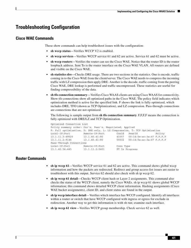
Implementing and Configuring the Cisco WAAS Solution
Troubleshooting Configuration
Cisco WAE Commands
These show commands can help troubleshoot issues with the configuration:
• sh wccp status—Verifies WCCP V2 is enabled.
• sh wccp services—Verifies WCCP service 61 and 62 are active. Service 61 and 62 must be active.
• sh wccp routers—Verifies the router can see the Cisco WAE. Notice that the router ID is the router loopback address. Sent To is the router interface on the Cisco WAE VLAN. All routers are defined and visible on the Cisco WAE.
• sh statistics dre—Checks DRE usage. There are two sections in the statistics. One is encode, traffic coming in to the Cisco WAE from the client/server. The Cisco WAE needs to compress the incoming traffic with LZ compression then apply DRE. Another is the decode, traffic coming from the peering Cisco WAE, DRE lookup is performed and traffic uncompressed. These statistics are useful for finding compressibility of the data.
• sh tfo connection summary—Verifies Cisco WAAS clients are using Cisco WAAS for connectivity. Show tfo connections show all optimized paths in the Cisco WAE. The policy field indicates which optimization method is active for the specified link. F shows the link is fully optimized, which includes DRE, TFO (shown as TCP Optimization), and LZ compression. Pass-through connections are connections that are not optimized.
The following is sample output from sh tfo connection summary. F,F,F,F means the connection is fully optimized with DRE/LZ and TCP Optimization.
Optimized Connection ListPolicy summary order: Our's, Peer's, Negotiated, AppliedF: Full optimization, D: DRE only, L: LZ Compression, T: TCP OptimizationLocal-IP:Port Remote-IP:Port ConId PeerId Policy13.1.11.3:49520 13.1.40.41:80 43357 00:14:5e:ac:3a:47 F,F,F,F13.1.11.2:9146 13.1.40.41:80 55532 00:14:5e:ac:3a:47 F,F,F,FPass-Through ConnectionsLocal-IP:Port Remote-IP:Port Conn Type13.1.42.54:445 13.1.11.2:5401 PT In Progress
Router Commands
• sh ip wccp 61—Verifies WCCP service 61 and 62 are active. This command shows global wccp information and how the packets are redirected. Redirect and group access-list issues are easier to troubleshoot with this output. Service 62 should also check with sh ip wccp 62.
• sh ip wccp 61 detail—Checks WCCP client hash or Layer 2 assignments. This command also checks the status of the WCCP client, namely the Cisco WAEs. sh ip wccp 61 shows global WCCP information; this command shows detailed WCCP client information. Hashing assignments (Cisco WAE bucket assignments), client ID, and client status are found in the output.
• sh ip wccp interface detail—Verifies which interface has WCCP configured. Identify all interfaces within a router or switch that have WCCP configured with ingress or egress for exclude-in redirection. Another way to get this information is with sh run; examine each interface.
• sh ip wccp 61 view—Verifies WCCP group membership. Check service 62 as well.
41
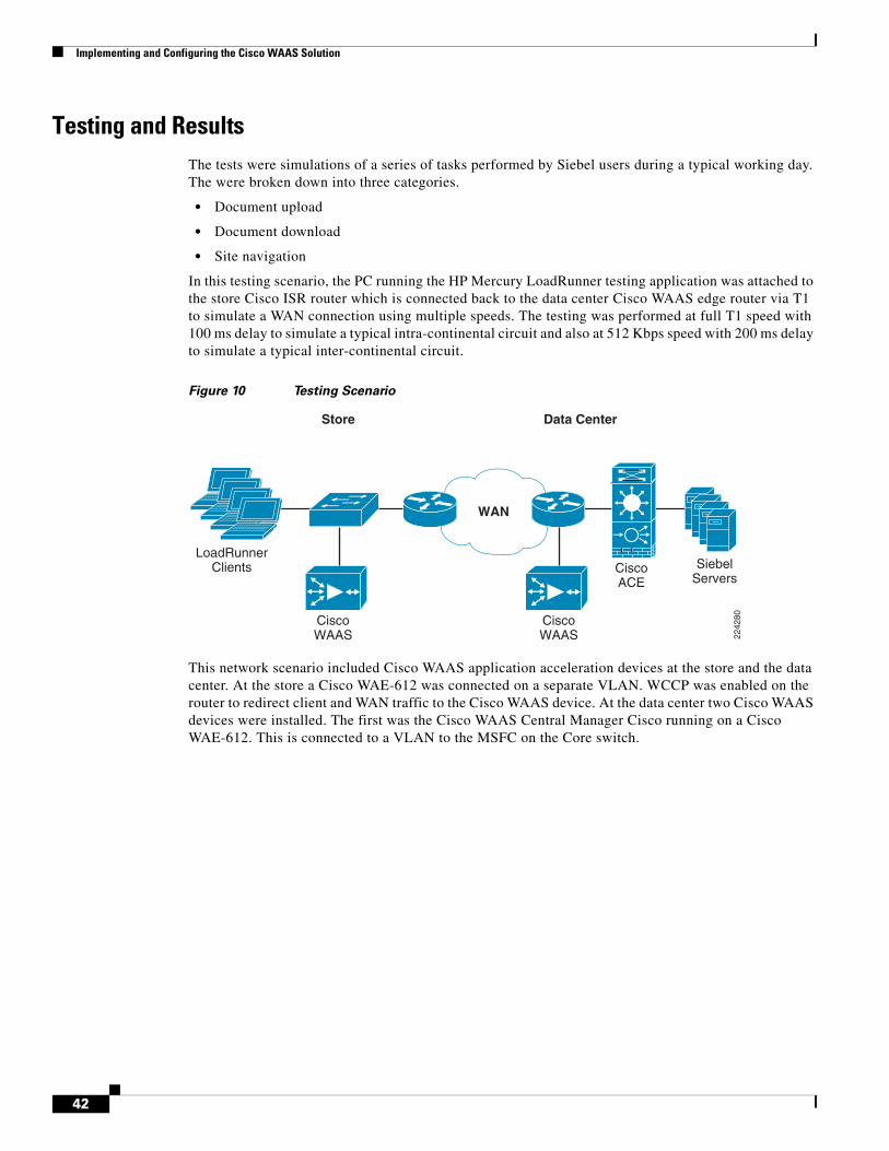
Implementing and Configuring the Cisco WAAS Solution
Testing and ResultsThe tests were simulations of a series of tasks performed by Siebel users during a typical working day. The were broken down into three categories.
• Document upload
• Document download
• Site navigation
In this testing scenario, the PC running the HP Mercury LoadRunner testing application was attached to the store Cisco ISR router which is connected back to the data center Cisco WAAS edge router via T1 to simulate a WAN connection using multiple speeds. The testing was performed at full T1 speed with 100 ms delay to simulate a typical intra-continental circuit and also at 512 Kbps speed with 200 ms delay to simulate a typical inter-continental circuit.
Figure 10 Testing Scenario
This network scenario included Cisco WAAS application acceleration devices at the store and the data center. At the store a Cisco WAE-612 was connected on a separate VLAN. WCCP was enabled on the router to redirect client and WAN traffic to the Cisco WAAS device. At the data center two Cisco WAAS devices were installed. The first was the Cisco WAAS Central Manager Cisco running on a Cisco WAE-612. This is connected to a VLAN to the MSFC on the Core switch.
2242
80
WAN
Store
CiscoWAAS
LoadRunnerClients Siebel
ServersCiscoACE
CiscoWAAS
Data Center
42
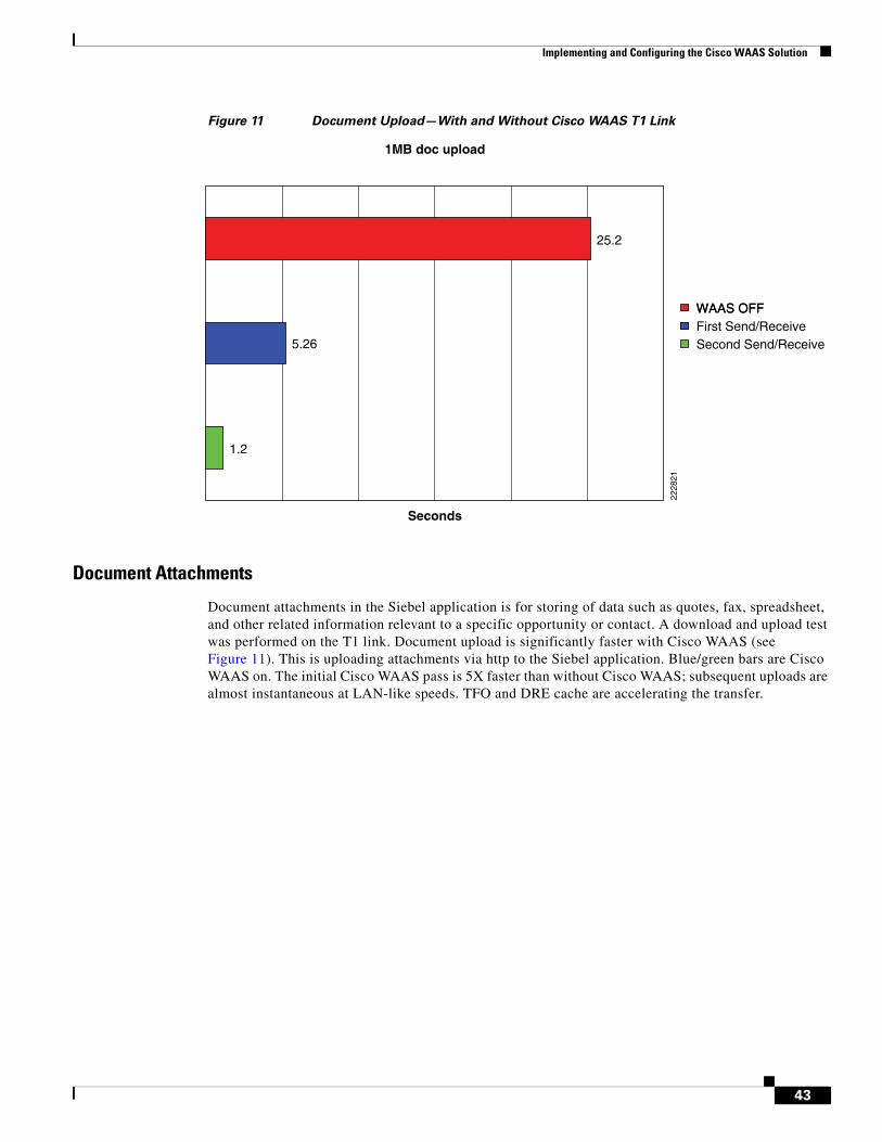
Implementing and Configuring the Cisco WAAS Solution
Figure 11 Document Upload—With and Without Cisco WAAS T1 Link
Document Attachments
Document attachments in the Siebel application is for storing of data such as quotes, fax, spreadsheet, and other related information relevant to a specific opportunity or contact. A download and upload test was performed on the T1 link. Document upload is significantly faster with Cisco WAAS (see Figure 11). This is uploading attachments via http to the Siebel application. Blue/green bars are Cisco WAAS on. The initial Cisco WAAS pass is 5X faster than without Cisco WAAS; subsequent uploads are almost instantaneous at LAN-like speeds. TFO and DRE cache are accelerating the transfer.
WAAS OFFFirst Send/Receive
2228
21
1MB doc upload
1.2
5.26
25.2
Seconds
WAAS OFF
Second Send/Receive
43
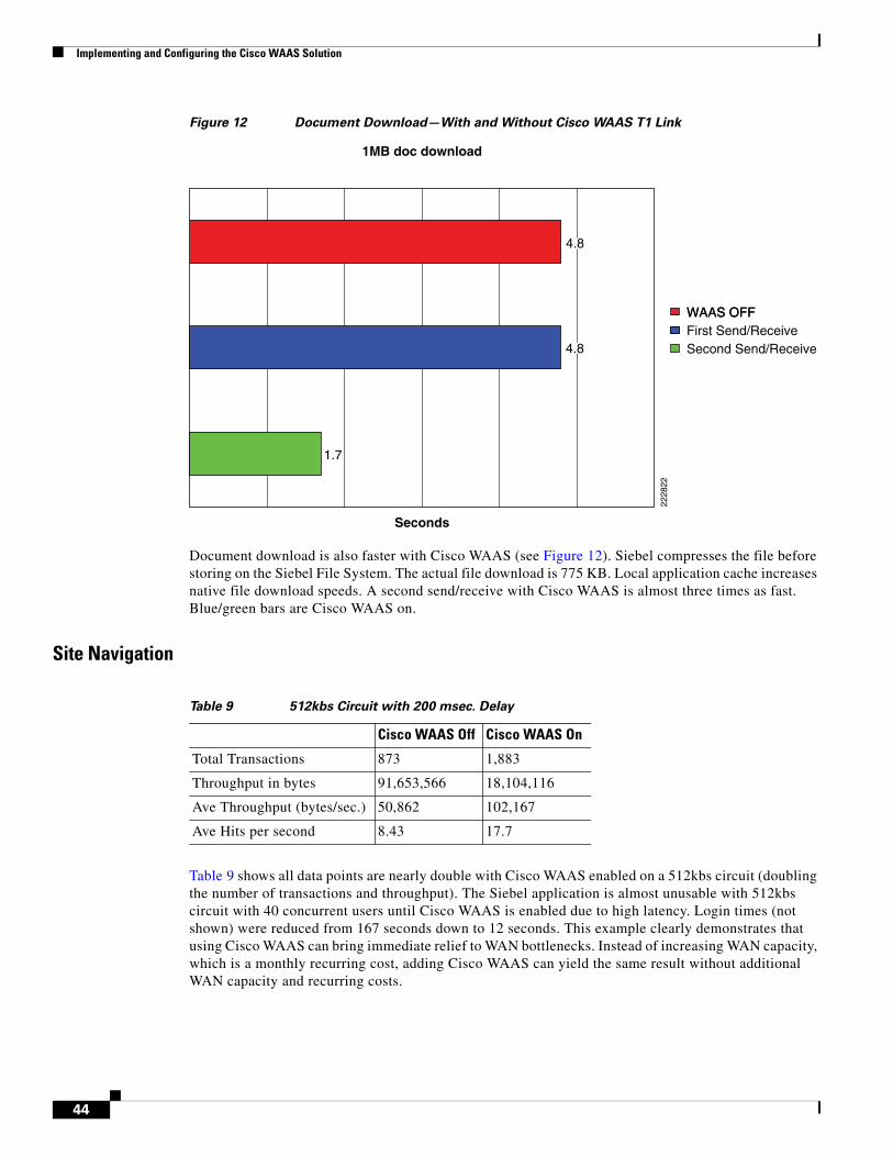
Implementing and Configuring the Cisco WAAS Solution
Figure 12 Document Download—With and Without Cisco WAAS T1 Link
Document download is also faster with Cisco WAAS (see Figure 12). Siebel compresses the file before storing on the Siebel File System. The actual file download is 775 KB. Local application cache increases native file download speeds. A second send/receive with Cisco WAAS is almost three times as fast. Blue/green bars are Cisco WAAS on.
Site Navigation
Table 9 shows all data points are nearly double with Cisco WAAS enabled on a 512kbs circuit (doubling the number of transactions and throughput). The Siebel application is almost unusable with 512kbs circuit with 40 concurrent users until Cisco WAAS is enabled due to high latency. Login times (not shown) were reduced from 167 seconds down to 12 seconds. This example clearly demonstrates that using Cisco WAAS can bring immediate relief to WAN bottlenecks. Instead of increasing WAN capacity, which is a monthly recurring cost, adding Cisco WAAS can yield the same result without additional WAN capacity and recurring costs.
WAAS OFFFirst Send/Receive
2228
22
1MB doc download
1.7
Seconds
WAAS OFF
Second Send/Receive4.8
4.8
Table 9 512kbs Circuit with 200 msec. Delay
Cisco WAAS Off Cisco WAAS On
Total Transactions 873 1,883
Throughput in bytes 91,653,566 18,104,116
Ave Throughput (bytes/sec.) 50,862 102,167
Ave Hits per second 8.43 17.7
44
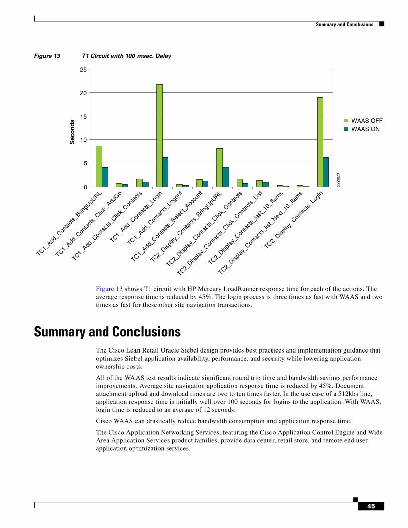
Summary and Conclusions
Figure 13 T1 Circuit with 100 msec. Delay
Figure 13 shows T1 circuit with HP Mercury LoadRunner response time for each of the actions. The average response time is reduced by 45%. The login process is three times as fast with WAAS and two times as fast for these other site navigation transactions.
Summary and ConclusionsThe Cisco Lean Retail Oracle Siebel design provides best practices and implementation guidance that optimizes Siebel application availability, performance, and security while lowering application ownership costs.
All of the WAAS test results indicate significant round trip time and bandwidth savings performance improvements. Average site navigation application response time is reduced by 45%. Document attachment upload and download times are two to ten times faster. In the use case of a 512kbs line, application response time is initially well over 100 seconds for logins to the application. With WAAS, login time is reduced to an average of 12 seconds.
Cisco WAAS can drastically reduce bandwidth consumption and application response time.
The Cisco Application Networking Services, featuring the Cisco Application Control Engine and Wide Area Application Services product families, provide data center, retail store, and remote end user application optimization services.
0
5
10
15
20
25S
eco
nd
s WAAS OFFWAAS ON
TC2_Disp
lay_C
onta
cts_L
ogin
TC2_Disp
lay_C
onta
cts_li
st_Nex
t_10
_Ite
ms
TC2_Disp
lay_C
onta
cts_la
st_10
_Ite
ms
TC2_Disp
lay_C
onta
cts_C
lick_
Conta
cts_L
ist
TC2_Disp
lay_C
onta
cts_C
lick_
Conta
cts
TC2_Disp
lay_C
onta
cts_B
ringU
pURL
TC1_Add
_Con
tacts
_Sele
ct_Acc
ount
TC1_Add
_Con
tacts
_Log
out
TC1_Add
_Con
tacts
_Log
in
TC1_Add
_Con
tacts
_Clic
k_Con
tacts
TC1_Add
_Con
tacts
_Clic
k_Add
Go
TC1_Add
_Con
tacts
_Brin
gUpU
RL
2228
20
45
Appendix A—Cisco ACE Configuration
Appendix A—Cisco ACE Configuration
Admin Contextlogin timeout 0hostname EDAL-AGG1-ACEboot system image:c6ace-t1k9-mz.3.0.0_A1_5a.bin! define Cisco ACE resource for each server farmresource-class WebFarm limit-resource all minimum 20.00 maximum unlimited limit-resource sticky minimum 40.00 maximum equal-to-minresource-class siebel-resource limit-resource all minimum 20.00 maximum unlimited limit-resource sticky minimum 40.00 maximum equal-to-minaccess-list ALLOW-TRAFFIC line 8 extended permit ip any anyaccess-list ALLOW-TRAFFIC line 9 extended permit icmp any anyclass-map type management match-any REMOTE-MGMT 2 match protocol ssh any 3 match protocol telnet any 4 match protocol icmp any 5 match protocol http any 6 match protocol https any
policy-map type management first-match REMOTE-ACCESS class REMOTE-MGMT permit
interface vlan 82 ip address 172.28.210.14 255.255.255.0 no icmp-guard access-group input ALLOW-TRAFFIC service-policy input REMOTE-ACCESS no shutdown
ft interface vlan 43 ip address 192.168.100.1 255.255.255.0 peer ip address 192.168.100.2 255.255.255.0 no shutdown
ft peer 1 heartbeat interval 200 heartbeat count 20 ft-interface vlan 43
ip route 0.0.0.0 0.0.0.0 172.28.210.1!define contexts within the Cisco ACEcontext Siebel allocate-interface vlan 42 allocate-interface vlan 100 member siebel-resourcecontext WebFarm allocate-interface vlan 41 allocate-interface vlan 101 member WebFarmft group 1 peer 1 priority 120 associate-context Siebel inserviceft group 2
46
Appendix A—Cisco ACE Configuration
peer 1 priority 120 associate-context WebFarm inserviceusername admin password 5 $1$faXJEFBj$TJR1Nx7sLPTi5BZ97v08c/ role Admin domaindefault-domainusername www password 5 $1$UZIiwUk7$QMVYN1JASaycabrHkhGcS/ role Admin domain default-domain
WebFarm Context!information for generating certificatecrypto csr-params testparms country US state California locality San Jose organization-name ESE organization-unit ESE common-name www.testsiebel.com serial-number cisco123
access-list ALLOW-TRAFFIC line 8 extended permit ip any anyaccess-list ALLOW-TRAFFIC line 9 extended permit icmp any any
probe http http-probe interval 30 expect status 200 200!configure TCP reuseparameter-map type http HTTP_PARAMETERS server-conn reuse case-insensitiveparameter-map type ssl SSL_PARAMETERS cipher RSA_WITH_RC4_128_MD5 version TLS1
rserver host websrvr1 description Siebel web server ip address 13.1.41.57 inservicerserver host websrvr2 description Siebel web server ip address 13.1.41.58 inservicerserver host websrvr3 description Siebel web server ip address 13.1.41.59 inservice! configure SSL proxy serverssl-proxy service SIEBELWEB_SSL key siebelweb.key cert siebelweb.cer
serverfarm host WEBFARM probe http-probe rserver websrvr1 80 inservice rserver websrvr2 80 inservice rserver websrvr3 80 inservice!define cookie sticky groupsticky http-cookie _sn sn_cookie
47
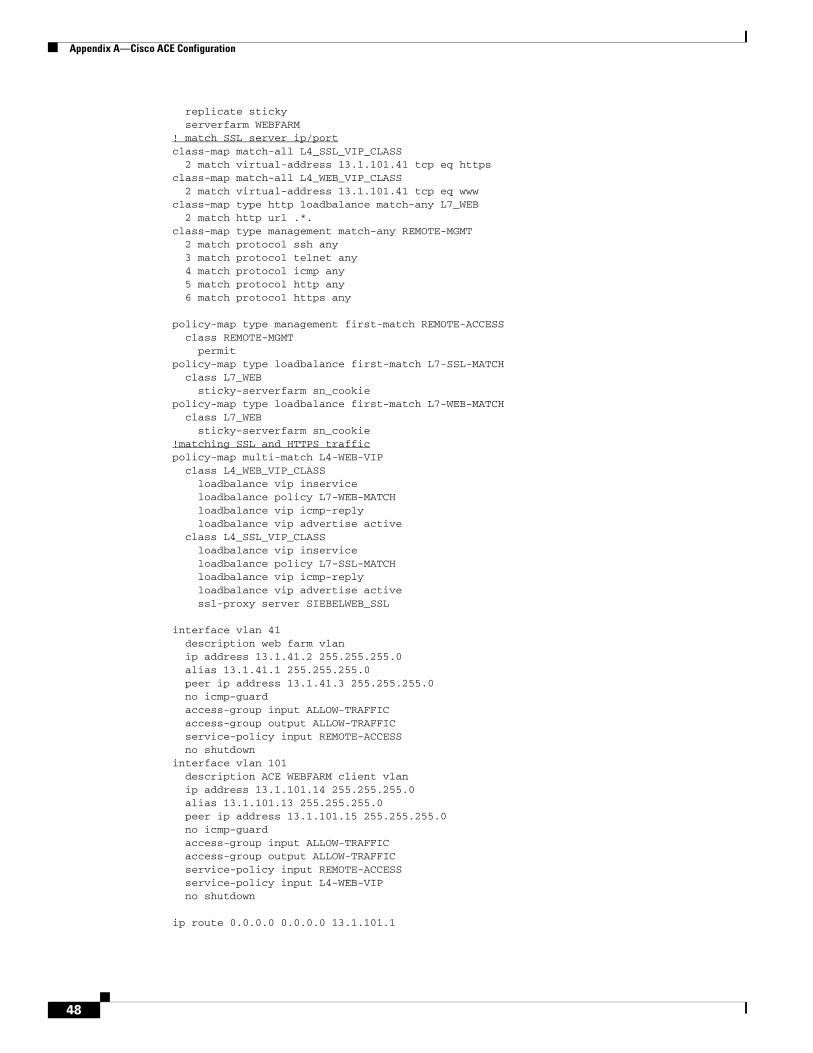
Appendix A—Cisco ACE Configuration
replicate sticky serverfarm WEBFARM! match SSL server ip/portclass-map match-all L4_SSL_VIP_CLASS 2 match virtual-address 13.1.101.41 tcp eq httpsclass-map match-all L4_WEB_VIP_CLASS 2 match virtual-address 13.1.101.41 tcp eq wwwclass-map type http loadbalance match-any L7_WEB 2 match http url .*.class-map type management match-any REMOTE-MGMT 2 match protocol ssh any 3 match protocol telnet any 4 match protocol icmp any 5 match protocol http any 6 match protocol https any
policy-map type management first-match REMOTE-ACCESS class REMOTE-MGMT permitpolicy-map type loadbalance first-match L7-SSL-MATCH class L7_WEB sticky-serverfarm sn_cookiepolicy-map type loadbalance first-match L7-WEB-MATCH class L7_WEB sticky-serverfarm sn_cookie!matching SSL and HTTPS trafficpolicy-map multi-match L4-WEB-VIP class L4_WEB_VIP_CLASS loadbalance vip inservice loadbalance policy L7-WEB-MATCH loadbalance vip icmp-reply loadbalance vip advertise active class L4_SSL_VIP_CLASS loadbalance vip inservice loadbalance policy L7-SSL-MATCH loadbalance vip icmp-reply loadbalance vip advertise active ssl-proxy server SIEBELWEB_SSL
interface vlan 41 description web farm vlan ip address 13.1.41.2 255.255.255.0 alias 13.1.41.1 255.255.255.0 peer ip address 13.1.41.3 255.255.255.0 no icmp-guard access-group input ALLOW-TRAFFIC access-group output ALLOW-TRAFFIC service-policy input REMOTE-ACCESS no shutdowninterface vlan 101 description ACE WEBFARM client vlan ip address 13.1.101.14 255.255.255.0 alias 13.1.101.13 255.255.255.0 peer ip address 13.1.101.15 255.255.255.0 no icmp-guard access-group input ALLOW-TRAFFIC access-group output ALLOW-TRAFFIC service-policy input REMOTE-ACCESS service-policy input L4-WEB-VIP no shutdown
ip route 0.0.0.0 0.0.0.0 13.1.101.1
48
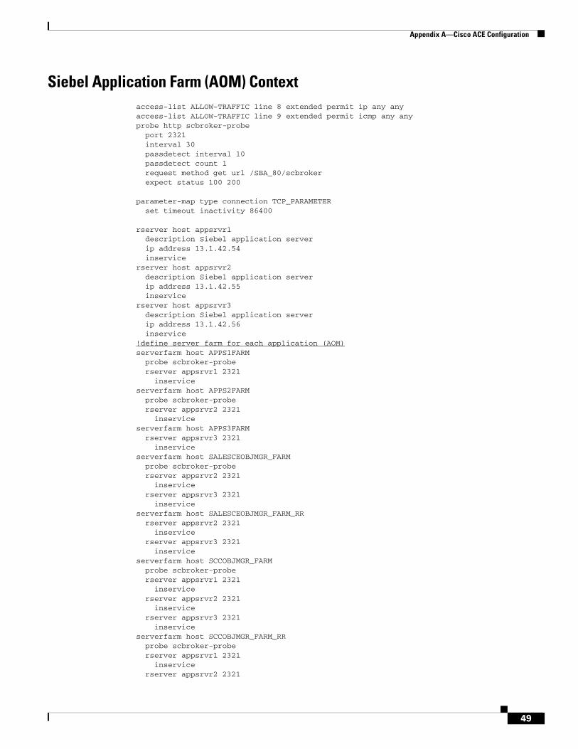
Appendix A—Cisco ACE Configuration
Siebel Application Farm (AOM) Contextaccess-list ALLOW-TRAFFIC line 8 extended permit ip any anyaccess-list ALLOW-TRAFFIC line 9 extended permit icmp any anyprobe http scbroker-probe port 2321 interval 30 passdetect interval 10 passdetect count 1 request method get url /SBA_80/scbroker expect status 100 200
parameter-map type connection TCP_PARAMETER set timeout inactivity 86400
rserver host appsrvr1 description Siebel application server ip address 13.1.42.54 inservicerserver host appsrvr2 description Siebel application server ip address 13.1.42.55 inservicerserver host appsrvr3 description Siebel application server ip address 13.1.42.56 inservice!define server farm for each application (AOM)serverfarm host APPS1FARM probe scbroker-probe rserver appsrvr1 2321 inserviceserverfarm host APPS2FARM probe scbroker-probe rserver appsrvr2 2321 inserviceserverfarm host APPS3FARM rserver appsrvr3 2321 inserviceserverfarm host SALESCEOBJMGR_FARM probe scbroker-probe rserver appsrvr2 2321 inservice rserver appsrvr3 2321 inserviceserverfarm host SALESCEOBJMGR_FARM_RR rserver appsrvr2 2321 inservice rserver appsrvr3 2321 inserviceserverfarm host SCCOBJMGR_FARM probe scbroker-probe rserver appsrvr1 2321 inservice rserver appsrvr2 2321 inservice rserver appsrvr3 2321 inserviceserverfarm host SCCOBJMGR_FARM_RR probe scbroker-probe rserver appsrvr1 2321 inservice rserver appsrvr2 2321
49
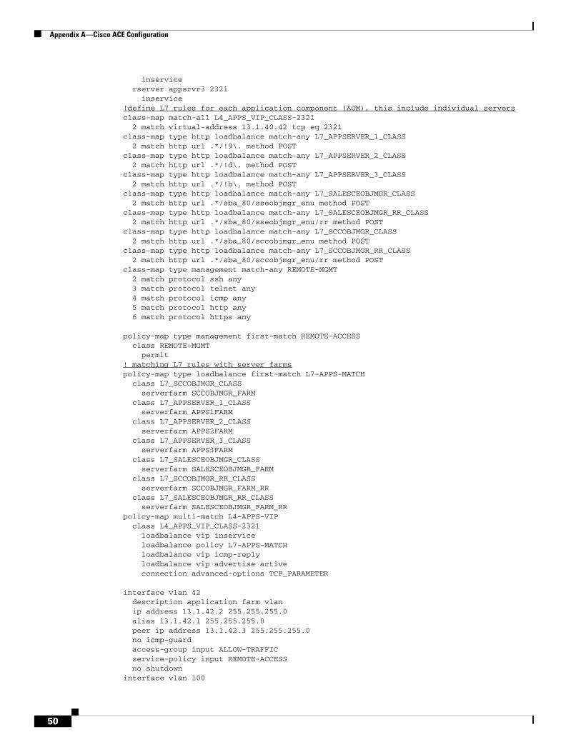
Appendix A—Cisco ACE Configuration
inservice rserver appsrvr3 2321 inservice!define L7 rules for each application component (AOM), this include individual serversclass-map match-all L4_APPS_VIP_CLASS-2321 2 match virtual-address 13.1.40.42 tcp eq 2321class-map type http loadbalance match-any L7_APPSERVER_1_CLASS 2 match http url .*/!9\. method POSTclass-map type http loadbalance match-any L7_APPSERVER_2_CLASS 2 match http url .*/!d\. method POSTclass-map type http loadbalance match-any L7_APPSERVER_3_CLASS 2 match http url .*/!b\. method POSTclass-map type http loadbalance match-any L7_SALESCEOBJMGR_CLASS 2 match http url .*/sba_80/sseobjmgr_enu method POSTclass-map type http loadbalance match-any L7_SALESCEOBJMGR_RR_CLASS 2 match http url .*/sba_80/sseobjmgr_enu/rr method POSTclass-map type http loadbalance match-any L7_SCCOBJMGR_CLASS 2 match http url .*/sba_80/sccobjmgr_enu method POSTclass-map type http loadbalance match-any L7_SCCOBJMGR_RR_CLASS 2 match http url .*/sba_80/sccobjmgr_enu/rr method POSTclass-map type management match-any REMOTE-MGMT 2 match protocol ssh any 3 match protocol telnet any 4 match protocol icmp any 5 match protocol http any 6 match protocol https any
policy-map type management first-match REMOTE-ACCESS class REMOTE-MGMT permit! matching L7 rules with server farmspolicy-map type loadbalance first-match L7-APPS-MATCH class L7_SCCOBJMGR_CLASS serverfarm SCCOBJMGR_FARM class L7_APPSERVER_1_CLASS serverfarm APPS1FARM class L7_APPSERVER_2_CLASS serverfarm APPS2FARM class L7_APPSERVER_3_CLASS serverfarm APPS3FARM class L7_SALESCEOBJMGR_CLASS serverfarm SALESCEOBJMGR_FARM class L7_SCCOBJMGR_RR_CLASS serverfarm SCCOBJMGR_FARM_RR class L7_SALESCEOBJMGR_RR_CLASS serverfarm SALESCEOBJMGR_FARM_RRpolicy-map multi-match L4-APPS-VIP class L4_APPS_VIP_CLASS-2321 loadbalance vip inservice loadbalance policy L7-APPS-MATCH loadbalance vip icmp-reply loadbalance vip advertise active connection advanced-options TCP_PARAMETER
interface vlan 42 description application farm vlan ip address 13.1.42.2 255.255.255.0 alias 13.1.42.1 255.255.255.0 peer ip address 13.1.42.3 255.255.255.0 no icmp-guard access-group input ALLOW-TRAFFIC service-policy input REMOTE-ACCESS no shutdowninterface vlan 100
50
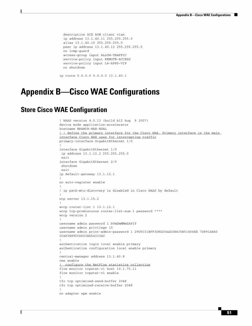
Appendix B—Cisco WAE Configurations
description ACE AOM client vlan ip address 13.1.40.11 255.255.255.0 alias 13.1.40.10 255.255.255.0 peer ip address 13.1.40.12 255.255.255.0 no icmp-guard access-group input ALLOW-TRAFFIC service-policy input REMOTE-ACCESS service-policy input L4-APPS-VIP no shutdown
ip route 0.0.0.0 0.0.0.0 13.1.40.1
Appendix B—Cisco WAE Configurations
Store Cisco WAE Configuration! WAAS version 4.0.13 (build b12 Aug 9 2007)device mode application-acceleratorhostname BRANCH-WAE-EDAL! ! define the primary interface for the Cisco WAE. Primary interface is the main interface Cisco WAE uses for intercepting trafficprimary-interface GigabitEthernet 1/0!interface GigabitEthernet 1/0 ip address 13.1.12.2 255.255.255.0 exitinterface GigabitEthernet 2/0 shutdown exitip default-gateway 13.1.12.1!no auto-register enable!! ip path-mtu-discovery is disabled in Cisco WAAS by default!ntp server 13.1.15.2!wccp router-list 1 13.1.12.1wccp tcp-promiscuous router-list-num 1 password ****wccp version 2!username admin password 1 bVmDmMMmZAPjYusername admin privilege 15username admin print-admin-password 1 29D5C31BFF3D8D25AAD3B435B51404EE 7D891AB402CAF2E89CCDD33ED54333AC!authentication login local enable primaryauthentication configuration local enable primary!central-manager address 13.1.40.8cms enable! configure the NetFlow statistics collectionflow monitor tcpstat-v1 host 10.1.70.11flow monitor tcpstat-v1 enable!tfo tcp optimized-send-buffer 2048tfo tcp optimized-receive-buffer 2048!no adapter epm enable
51
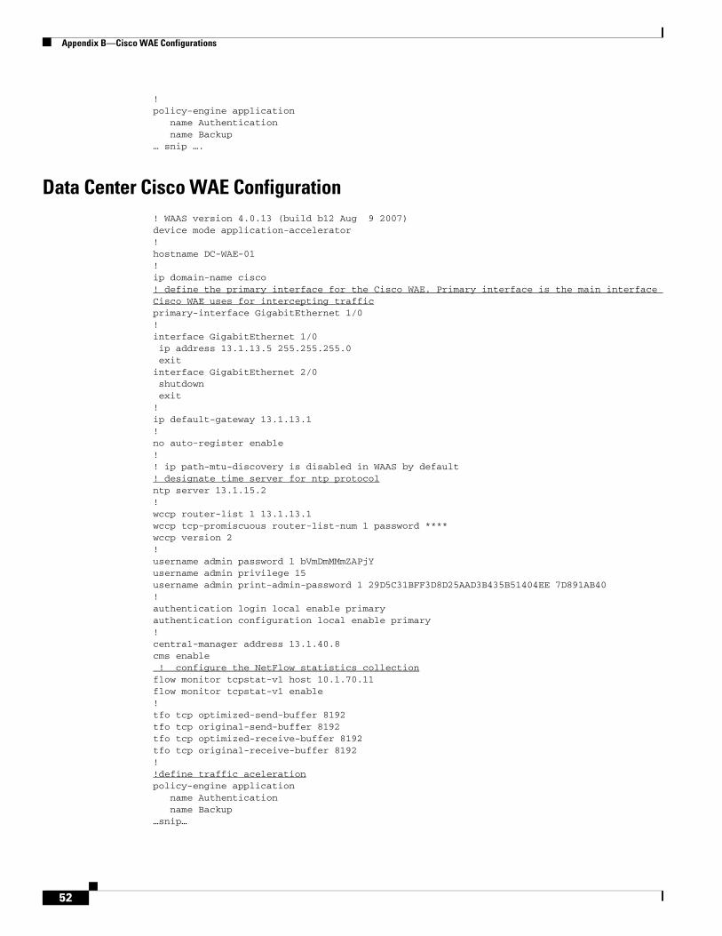
Appendix B—Cisco WAE Configurations
!policy-engine application name Authentication name Backup… snip ….
Data Center Cisco WAE Configuration! WAAS version 4.0.13 (build b12 Aug 9 2007)device mode application-accelerator!hostname DC-WAE-01!ip domain-name cisco! define the primary interface for the Cisco WAE. Primary interface is the main interface Cisco WAE uses for intercepting trafficprimary-interface GigabitEthernet 1/0!interface GigabitEthernet 1/0 ip address 13.1.13.5 255.255.255.0 exitinterface GigabitEthernet 2/0 shutdown exit!ip default-gateway 13.1.13.1!no auto-register enable!! ip path-mtu-discovery is disabled in WAAS by default! designate time server for ntp protocolntp server 13.1.15.2!wccp router-list 1 13.1.13.1wccp tcp-promiscuous router-list-num 1 password ****wccp version 2!username admin password 1 bVmDmMMmZAPjYusername admin privilege 15username admin print-admin-password 1 29D5C31BFF3D8D25AAD3B435B51404EE 7D891AB40!authentication login local enable primaryauthentication configuration local enable primary! central-manager address 13.1.40.8cms enable ! configure the NetFlow statistics collectionflow monitor tcpstat-v1 host 10.1.70.11flow monitor tcpstat-v1 enable!tfo tcp optimized-send-buffer 8192tfo tcp original-send-buffer 8192tfo tcp optimized-receive-buffer 8192tfo tcp original-receive-buffer 8192!!define traffic acelerationpolicy-engine application name Authentication name Backup…snip…
52
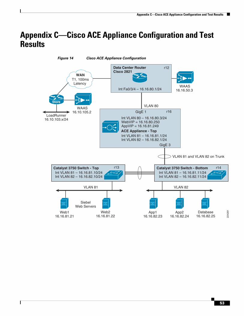
Appendix C—Cisco ACE Appliance Configuration and Test Results
Appendix C—Cisco ACE Appliance Configuration and Test Results
Figure 14 Cisco ACE Appliance Configuration
VLAN 82
VLAN 80
App116.16.82.23
Database16.16.82.25
App216.16.82.24
VLAN 81 and VLAN 82 on Trunk
ACE Appliance - Top
r16
r12
r13 r14Catalyst 3750 Switch - Bottom Catalyst 3750 Switch - Top
GigE 3
GigE 1
Data Center RouterCisco 2821
Int Fa0/3/4 – 16.16.80.1/24
Int VLAN 80 – 16.16.80.3/24WebVIP = 16.16.80.250AppVIP = 16.16.81.249
Int VLAN 81 – 16.16.81.1/24Int VLAN 82 – 16.16.82.1/24
T1, 100msLatency
LoadRunner16.10.103.x/24
Int VLAN 81 – 16.16.81.11/24Int VLAN 82 – 16.16.82.11/24
Int VLAN 81 – 16.16.81.10/24Int VLAN 82 – 16.16.82.10/24
WAAS16.10.105.2
WAAS16.16.50.3
WAN
Store
VLAN 81
SiebelWeb Servers
Web116.16.81.21
Web216.16.81.22 22
4281
53
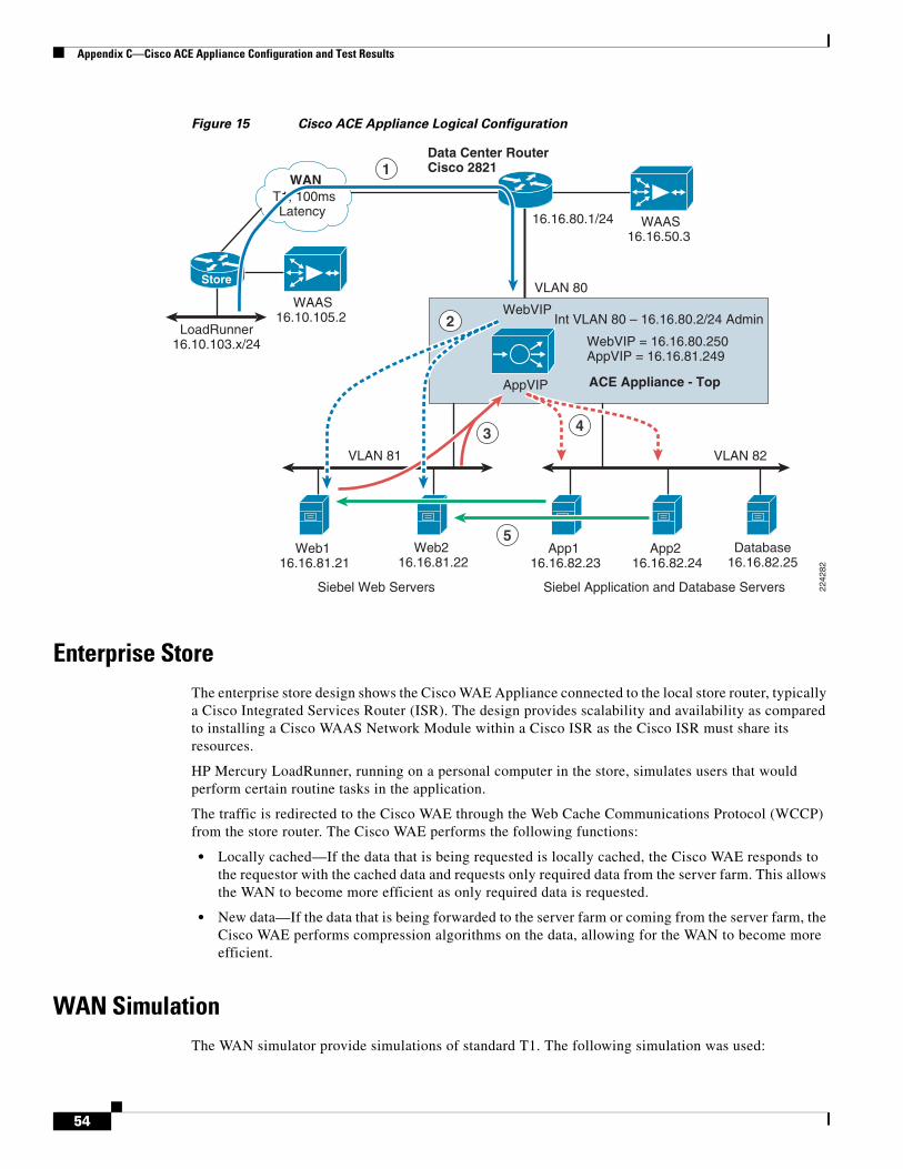
Appendix C—Cisco ACE Appliance Configuration and Test Results
Figure 15 Cisco ACE Appliance Logical Configuration
Enterprise StoreThe enterprise store design shows the Cisco WAE Appliance connected to the local store router, typically a Cisco Integrated Services Router (ISR). The design provides scalability and availability as compared to installing a Cisco WAAS Network Module within a Cisco ISR as the Cisco ISR must share its resources.
HP Mercury LoadRunner, running on a personal computer in the store, simulates users that would perform certain routine tasks in the application.
The traffic is redirected to the Cisco WAE through the Web Cache Communications Protocol (WCCP) from the store router. The Cisco WAE performs the following functions:
• Locally cached—If the data that is being requested is locally cached, the Cisco WAE responds to the requestor with the cached data and requests only required data from the server farm. This allows the WAN to become more efficient as only required data is requested.
• New data—If the data that is being forwarded to the server farm or coming from the server farm, the Cisco WAE performs compression algorithms on the data, allowing for the WAN to become more efficient.
WAN SimulationThe WAN simulator provide simulations of standard T1. The following simulation was used:
VLAN 82
VLAN 80
App1 16.16.82.23
Database16.16.82.25
App2 16.16.82.24
ACE Appliance - Top
WebVIP
AppVIP
Data Center RouterCisco 2821
16.16.80.1/24
WebVIP = 16.16.80.250AppVIP = 16.16.81.249
Int VLAN 80 – 16.16.80.2/24 Admin
T1, 100msLatency
LoadRunner16.10.103.x/24
WAAS16.10.105.2
WAAS16.16.50.3
WAN
Store
VLAN 81
Siebel Web Servers Siebel Application and Database Servers
Web1 16.16.81.21
Web2 16.16.81.22
2242
82
1
2
3 4
5
54
Appendix C—Cisco ACE Appliance Configuration and Test Results
• WAN Type 1 (Intracontinental)
– Bandwidth-1.544 Mbps, ESF, B8ZS
– Delay-100 mS
– Loss-Drop one packet in every 1000 packets
Data CenterFor this design, the Cisco ACE Appliance is targeted for a small-to-medium data center (DC). The DC follows the design guidelines found in the Data Center Infrastructure Design Guide found at: http://www.cisco.com/go/srnd.
The design consists of a DC WAN router, a collapsed core/aggregation, access, and the server farm (where the application resides). In this appendix, the focus is on the DC WAN router, aggregation, and the server farm. The core provides routing to and from the DC WAN router and the aggregation. The access layer provides Layer 2 connectivity for the server farms to the aggregation. For larger deployments, one should consider a separate core and aggregation layer, or a one-arm deployment where the Cisco ACE Appliance connects to a Cisco 6500. For more information, refer to:
http://www.cisco.com/en/US/partner/products/ps7027/tsd_products_support_series_home.html
The DC WAN router performs the same function as the store WAN router by redirecting traffic to the DC WAE. The DC WAE performs the following:
• Locally cached—If the data that is being requested is locally cache, the WAE responds to the requestor with the cached data and requests only required data from the store. This allows the WAN to become more efficient as only required data is requested.
• New data—If the data is being forwarded to the store or coming from the store, the WAE performs compression algorithms on the data, allowing for the WAN to become more efficient.
Within a Cisco WAAS topology, each Cisco WAE runs a process called central management system (CMS). The CMS process provides SSL-encrypted bidirectional configuration synchronization of the Cisco WAAS Central Manager and the Cisco WAE devices. The CMS process is also used to exchange reporting information and statistics at a configurable interval. When the administrator applies configuration or policy changes to a Cisco WAE device or a group of Cisco WAE devices (a device group), the Cisco WAAS Central Manager automatically propagates the changes to each of the managed Cisco WAE devices. Cisco WAE devices that are not available to receive the update receive the update the next time they become available.
Note Cisco WAEs out of box have a standard set of application variables and ports that are defined for optimization. In this solution no changes need to be made to the standard default configuration of the Cisco WAEs.
The aggregation segment contains the Cisco ACE Appliance. The Cisco ACE Appliance provides the following:
• Virtualization—Device partitioning, where the Cisco ACE has multiple contexts. Each context can be configured for different applications and each context is independent of the other. The Cisco ACE is configured with Admin context and the Siebel context. Note that the Cisco ACE can support up to 20 contexts (dependent on the license).
• Session Persistence—The ability to forward client requests to the same server for the duration of the session. The Siebel application requires cookie stickiness session persistence.
55
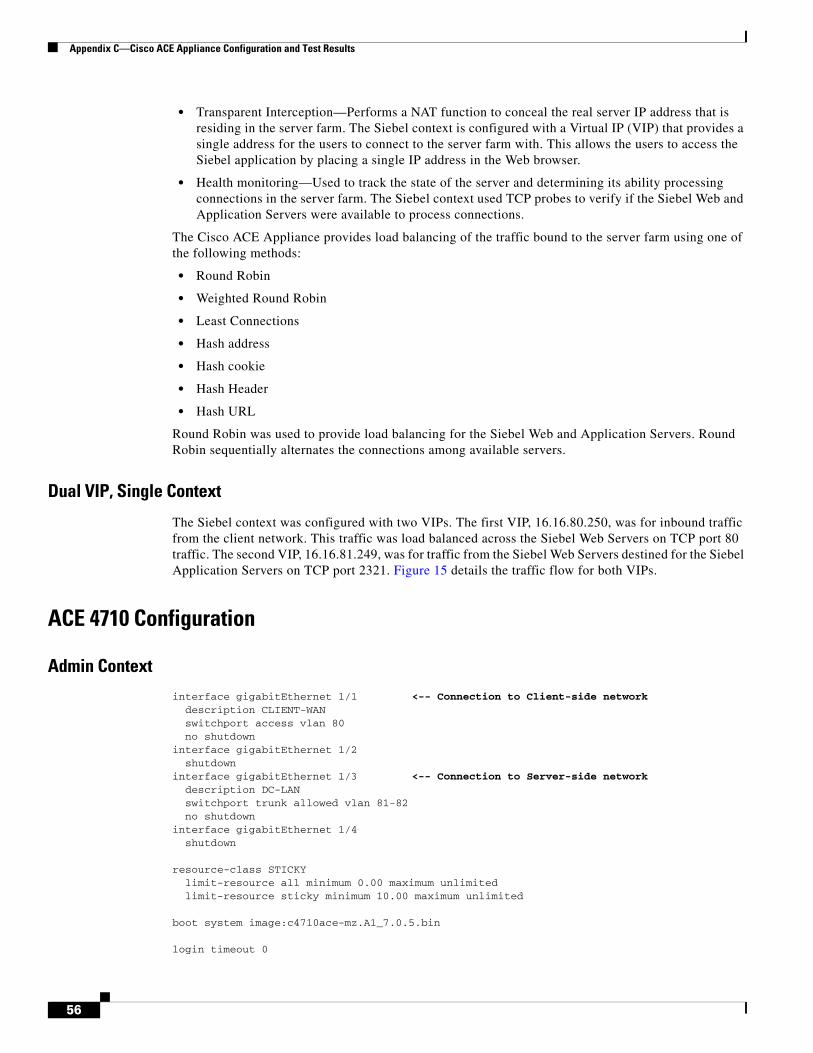
Appendix C—Cisco ACE Appliance Configuration and Test Results
• Transparent Interception—Performs a NAT function to conceal the real server IP address that is residing in the server farm. The Siebel context is configured with a Virtual IP (VIP) that provides a single address for the users to connect to the server farm with. This allows the users to access the Siebel application by placing a single IP address in the Web browser.
• Health monitoring—Used to track the state of the server and determining its ability processing connections in the server farm. The Siebel context used TCP probes to verify if the Siebel Web and Application Servers were available to process connections.
The Cisco ACE Appliance provides load balancing of the traffic bound to the server farm using one of the following methods:
• Round Robin
• Weighted Round Robin
• Least Connections
• Hash address
• Hash cookie
• Hash Header
• Hash URL
Round Robin was used to provide load balancing for the Siebel Web and Application Servers. Round Robin sequentially alternates the connections among available servers.
Dual VIP, Single Context
The Siebel context was configured with two VIPs. The first VIP, 16.16.80.250, was for inbound traffic from the client network. This traffic was load balanced across the Siebel Web Servers on TCP port 80 traffic. The second VIP, 16.16.81.249, was for traffic from the Siebel Web Servers destined for the Siebel Application Servers on TCP port 2321. Figure 15 details the traffic flow for both VIPs.
ACE 4710 Configuration
Admin Context
interface gigabitEthernet 1/1 <-- Connection to Client-side network description CLIENT-WAN switchport access vlan 80 no shutdowninterface gigabitEthernet 1/2 shutdowninterface gigabitEthernet 1/3 <-- Connection to Server-side network description DC-LAN switchport trunk allowed vlan 81-82 no shutdowninterface gigabitEthernet 1/4 shutdown
resource-class STICKY limit-resource all minimum 0.00 maximum unlimited limit-resource sticky minimum 10.00 maximum unlimited
boot system image:c4710ace-mz.A1_7.0.5.bin
login timeout 0
56
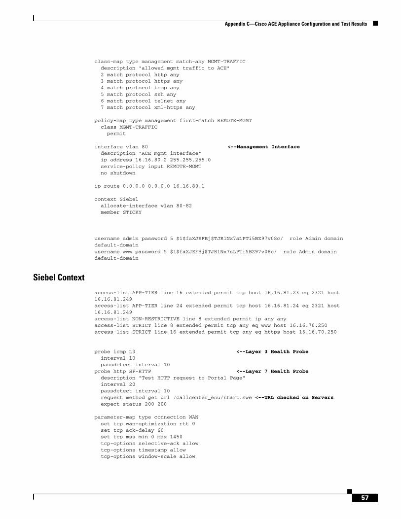
Appendix C—Cisco ACE Appliance Configuration and Test Results
class-map type management match-any MGMT-TRAFFIC description "allowed mgmt traffic to ACE" 2 match protocol http any 3 match protocol https any 4 match protocol icmp any 5 match protocol ssh any 6 match protocol telnet any 7 match protocol xml-https any
policy-map type management first-match REMOTE-MGMT class MGMT-TRAFFIC permit
interface vlan 80 <--Management Interface description "ACE mgmt interface" ip address 16.16.80.2 255.255.255.0 service-policy input REMOTE-MGMT no shutdown
ip route 0.0.0.0 0.0.0.0 16.16.80.1
context Siebel allocate-interface vlan 80-82 member STICKY
username admin password 5 $1$faXJEFBj$TJR1Nx7sLPTi5BZ97v08c/ role Admin domain default-domain username www password 5 $1$faXJEFBj$TJR1Nx7sLPTi5BZ97v08c/ role Admin domain default-domain
Siebel Context
access-list APP-TIER line 16 extended permit tcp host 16.16.81.23 eq 2321 host 16.16.81.249 access-list APP-TIER line 24 extended permit tcp host 16.16.81.24 eq 2321 host 16.16.81.249 access-list NON-RESTRICTIVE line 8 extended permit ip any any access-list STRICT line 8 extended permit tcp any eq www host 16.16.70.250 access-list STRICT line 16 extended permit tcp any eq https host 16.16.70.250
probe icmp L3 <--Layer 3 Health Probe interval 10 passdetect interval 10probe http SP-HTTP <--Layer 7 Health Probe description "Test HTTP request to Portal Page" interval 20 passdetect interval 10 request method get url /callcenter_enu/start.swe <--URL checked on Servers expect status 200 200
parameter-map type connection WAN set tcp wan-optimization rtt 0 set tcp ack-delay 60 set tcp mss min 0 max 1450 tcp-options selective-ack allow tcp-options timestamp allow tcp-options window-scale allow
57
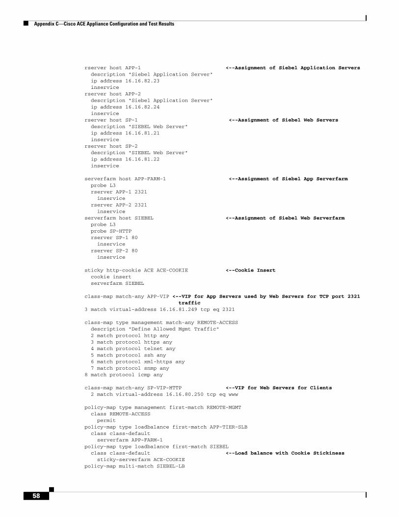
Appendix C—Cisco ACE Appliance Configuration and Test Results
rserver host APP-1 <--Assignment of Siebel Application Servers description "Siebel Application Server" ip address 16.16.82.23 inservicerserver host APP-2 description "Siebel Application Server" ip address 16.16.82.24 inservicerserver host SP-1 <--Assignment of Siebel Web Servers description "SIEBEL Web Server" ip address 16.16.81.21 inservicerserver host SP-2 description "SIEBEL Web Server" ip address 16.16.81.22 inservice
serverfarm host APP-FARM-1 <--Assignment of Siebel App Serverfarm probe L3 rserver APP-1 2321 inservice rserver APP-2 2321 inserviceserverfarm host SIEBEL <--Assignment of Siebel Web Serverfarm probe L3 probe SP-HTTP rserver SP-1 80 inservice rserver SP-2 80 inservice
sticky http-cookie ACE ACE-COOKIE <--Cookie Insert cookie insert serverfarm SIEBEL
class-map match-any APP-VIP <--VIP for App Servers used by Web Servers for TCP port 2321 traffic
3 match virtual-address 16.16.81.249 tcp eq 2321
class-map type management match-any REMOTE-ACCESS description "Define Allowed Mgmt Traffic" 2 match protocol http any 3 match protocol https any 4 match protocol telnet any 5 match protocol ssh any 6 match protocol xml-https any 7 match protocol snmp any8 match protocol icmp any
class-map match-any SP-VIP-HTTP <--VIP for Web Servers for Clients 2 match virtual-address 16.16.80.250 tcp eq www
policy-map type management first-match REMOTE-MGMT class REMOTE-ACCESS permitpolicy-map type loadbalance first-match APP-TIER-SLB class class-default serverfarm APP-FARM-1policy-map type loadbalance first-match SIEBEL class class-default <--Load balance with Cookie Stickiness sticky-serverfarm ACE-COOKIE policy-map multi-match SIEBEL-LB
58
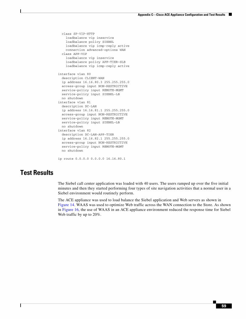
Appendix C—Cisco ACE Appliance Configuration and Test Results
class SP-VIP-HTTP loadbalance vip inservice loadbalance policy SIEBEL loadbalance vip icmp-reply active connection advanced-options WAN class APP-VIP loadbalance vip inservice loadbalance policy APP-TIER-SLB loadbalance vip icmp-reply active
interface vlan 80 description CLIENT-WAN ip address 16.16.80.3 255.255.255.0 access-group input NON-RESTRICTIVE service-policy input REMOTE-MGMT service-policy input SIEBEL-LB no shutdowninterface vlan 81 description DC-LAN ip address 16.16.81.1 255.255.255.0 access-group input NON-RESTRICTIVE service-policy input REMOTE-MGMT service-policy input SIEBEL-LB no shutdowninterface vlan 82 description DC-LAN-APP-TIER ip address 16.16.82.1 255.255.255.0 access-group input NON-RESTRICTIVE service-policy input REMOTE-MGMT no shutdown
ip route 0.0.0.0 0.0.0.0 16.16.80.1
Test ResultsThe Siebel call center application was loaded with 40 users. The users ramped up over the five initial minutes and then they started performing four types of site navigation activities that a normal user in a Siebel environment would routinely perform.
The ACE appliance was used to load balance the Siebel application and Web servers as shown in Figure 14. WAAS was used to optimize Web traffic across the WAN connection to the Store. As shown in Figure 16, the use of WAAS in an ACE appliance environment reduced the response time for Siebel Web traffic by up to 20%.
59
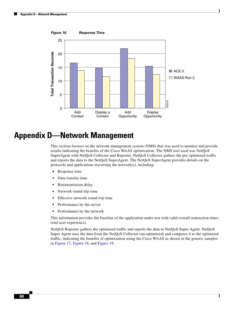
Appendix D—Network Management
Figure 16 Response Time
Appendix D—Network ManagementThis section focuses on the network management system (NMS) that was used to monitor and provide results indicating the benefits of the Cisco WAAS optimization. The NMS tool used was NetQoS SuperAgent with NetQoS Collector and Reporter. NetQoS Collector gathers the pre-optimized traffic and reports the data to the NetQoS SuperAgent. The NetQoS SuperAgent provides details on the protocols and applications traversing the network(s), including:
• Response time
• Data transfer time
• Retransmission delay
• Network round trip time
• Effective network round trip time
• Performance by the server
• Performance by the network
This information provides the baseline of the application under test with valid overall transaction times (end user experience).
NetQoS Reporter gathers the optimized traffic and reports the data to NetQoS Super Agent. NetQoS Super Agent uses the data from the NetQoS Collector (un-optimized) and compares it to the optimized traffic, indicating the benefits of optimization using the Cisco WAAS as shown in the generic samples in Figure 17, Figure 18, and Figure 19.
ACE-2
WAAS Run 2
2235
16
0
25
20
15
10
5
AddContact
Display aContact
AddOpportunity
DisplayOpportunity
To
tal T
ran
sact
ion
Sec
on
ds
60
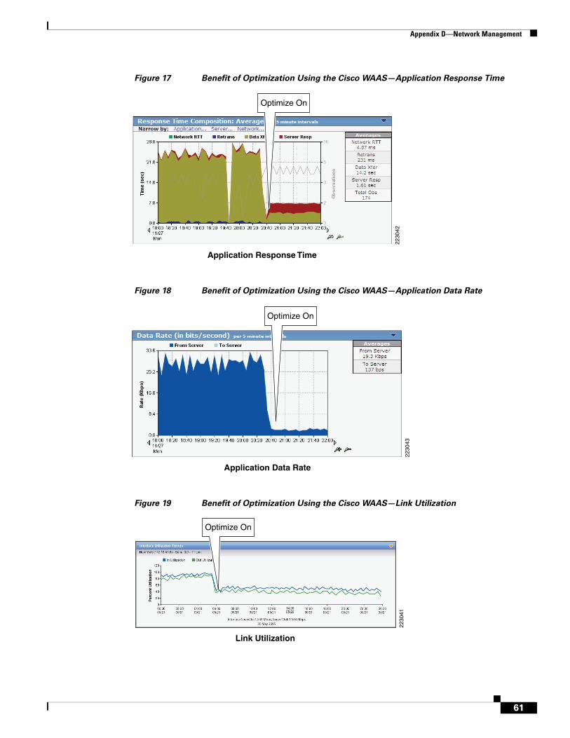
Appendix D—Network Management
Figure 17 Benefit of Optimization Using the Cisco WAAS—Application Response Time
Figure 18 Benefit of Optimization Using the Cisco WAAS—Application Data Rate
Figure 19 Benefit of Optimization Using the Cisco WAAS—Link Utilization
Application Response Time
2230
42
Optimize On
Application Data Rate
2230
43
Optimize On
Link Utilization
Optimize On
2230
41
61
Appendix E—Cisco Advanced Services
NetQoS devices passively listen in by using the rspan feature of Cisco routers and switches. They do not poll servers and hence do not add to the server load. For more information about this tool, see:
http://www.netqos.com/CiscoWAASSolutions/Cisco_WAAS_overview.html
Appendix E—Cisco Advanced Services
Cisco Services Help Accelerate and Optimize ANS DeploymentsApplication deployments are complex projects. Cisco Services can help mitigate the risk of making changes to the environment and accelerate deployment of Cisco ANS solutions. Our product and technology expertise is constantly enhanced by hands-on experience with real-life networks and broad exposure to the latest technology and implementations. Cisco uses leading practices to help our customers define their IT and business requirements and help them deliver fast, secure and highly available application access in a scalable environment.
• The Cisco Application Control Engine Planning and Design Service helps customers accelerate deployment of a Cisco ACE solution for fast, secure application access in a scalable environment.
• The Cisco Application Control Engine Optimization Services help customers continuously update and optimize their Cisco Application Control Engine solution as their applications delivery environment changes.
• The Cisco Wide Area Application Services Planning and Design Service helps customers accelerate deployment of Cisco WAAS solutions and improve application responsiveness across their wide area networks.
• The Cisco Wide Area Application Services Optimization Services help customers maintain or improve application responsiveness across wide area network as their business changes and grows.
• The Cisco Application Profiling Service helps customers host and manage applications more effectively while preserving application performance, security, and availability.
Cisco ANS Services:
http://www.cisco.com/en/US/products/ps6892/serv_group_home.html
http://www.cisco.com/en/US/products/ps6894/serv_group_home.html
62