Embed Size (px)
Citation preview
More user manuals on ManualsBase.com
7 Augus t 20 03
Cisco O78-14228-02
C H A P T E R 1
thetok),
t
lly
ch
Cisco ONS 15530 Overview
The Cisco ONS 15530 is a modular and scalable optical switching andaggregation platform designed to supplement the Cisco ONS 15540 ESP. WithCisco ONS 15530, users can take advantage of the availability of dark fiber build a common infrastructure that supports data, SAN (storage area networand TDM (time-division multiplexing) traffic. For more information aboutDWDM technology and applications, refer to theIntroduction to DWDMTechnologypublication and theCisco ONS 15530 Planning and Design Guide.
The Cisco ONS 15530 is designed to meet or exceed stringent ISP (Interneservice provider) requirements for product availability and reliability.
Note Before you install, operate, or service the system, read theRegulatoryCompliance and Safety Information for the Cisco ONS 15500 Seriesfor importantsafety information you should know before working with the system.
This chapter includes the following sections:
• Cisco ONS 15530 Chassis, page 1-1
• Cisco ONS 15530 Components, page 1-11
Cisco ONS 15530 ChassisThe Cisco ONS 15530 is available in two configurations. Both have two verticastacked half-height slots specifically for the optical OADM (optical add dropmultiplexing) modules, and 10 vertically oriented slots that hold the CPU swit
1-1NS 15530 Hardware Installation Guide
More user man
7 Augus t 20 03
Chapter 1 Cisco ONS 15530 OverviewCisco ONS 15530 Chassis
halfhes.
nletcated. All
sis
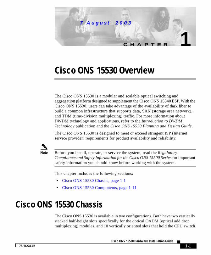
modules, line cards, and 2.5-G transponder trunk line cards. Slot 0 holds twoheight optical OADM modules. Slots 1 through 4 and slots 7 through 10 hold tline cards and transponder cards. Slots 5 and 6 hold the CPU switch modulePower supplies are located on the right side of the chassis next to slot 10. Air iand fan tray assembly are located beneath the slots. Cable management is lobeneath the slots. The system has an electrical backplane for system controloptical connections are located on the front of the cards.Figure 1-1shows a fullypopulated chassis.
Figure 1-1 Cisco ONS 15530 Shelf
The chassis configurations differ in how cooling air is routed through the chasand where the lifting handles are placed.
7767
0
FASTENERS MUST BEFULLY ENGAGED PRIOR TOOPERATING THE POWER SUPPLYFAIL
100-240V8.0-3.5A50-60HZ
GOOD
STATUS
TXRX
TXRX
TXRX
TXRX
TXRX
TXRX
TXRX
TXRX
TXRX
TXRX
15
53
0-L
CM
B-0
20
0
0
1
2
3
4
5
6
7
8
9
STATUS
TXRX
TXRX
TXRX
TXRX
TXRX
TXRX
TXRX
TXRX
TXRX
TXRX
15
53
0-L
CM
B-0
20
0
0
1
2
3
4
5
6
7
8
9
STATUS
TXRX
TXRX
TXRX
TXRX
TXRX
TXRX
TXRX
TXRX
TXRX
TXRX
15
53
0-L
CM
B-0
20
0
0
1
2
3
4
5
6
7
8
9
STATUS
TXRX
TXRX
TXRX
TXRX
TXRX
TXRX
TXRX
TXRX
TXRX
TXRX
15
53
0-L
CM
B-0
20
0
0
1
2
3
4
5
6
7
8
9
STATUS
TXRX
TXRX
TXRX
TXRX
TXRX
TXRX
TXRX
TXRX
TXRX
TXRX
15
53
0-L
CM
B-0
20
0
0
1
2
3
4
5
6
7
8
9
STATUS
STATUS
RESET
ACTIVE
COMPACT
FLASH
CIRTICAL
MAJO
R
FDX
100MBPS
CUTOFF
HIST
CLR
15
53
0-C
PU
ALARMS
RESET
ACTIVE
COMPACT
FLASH
CIRTICAL
MAJO
R
FDX
100MBPS
LINK
LINK
AUX
CON
CON
CUTOFF
HIST
CLR
CUTOFF
MINOR
15
53
0-C
PU
ALARMS
AUX
CON
STATUS
TX
TX
TX
EAST
WEST
RX
TX
RX
RX
RX
TX
RX
STATUS
TX
TX
TX
EAST
WEST
RX
TX
RX
RX
RX
TX
RX
STATUS
TX
TX
EAST
WEST
RX
TX
RX
RX
FAN
STATUS
uals on ManualsBase.com
1-2Cisco ONS 15530 Hardware Installation Guide
78-14228-02
More user man
7 Augus t 20 03
Chapter 1 Cisco ONS 15530 OverviewCisco ONS 15530 Chassis
0.1
s and
Cisco ONS 15530-CHAS-E Chassis
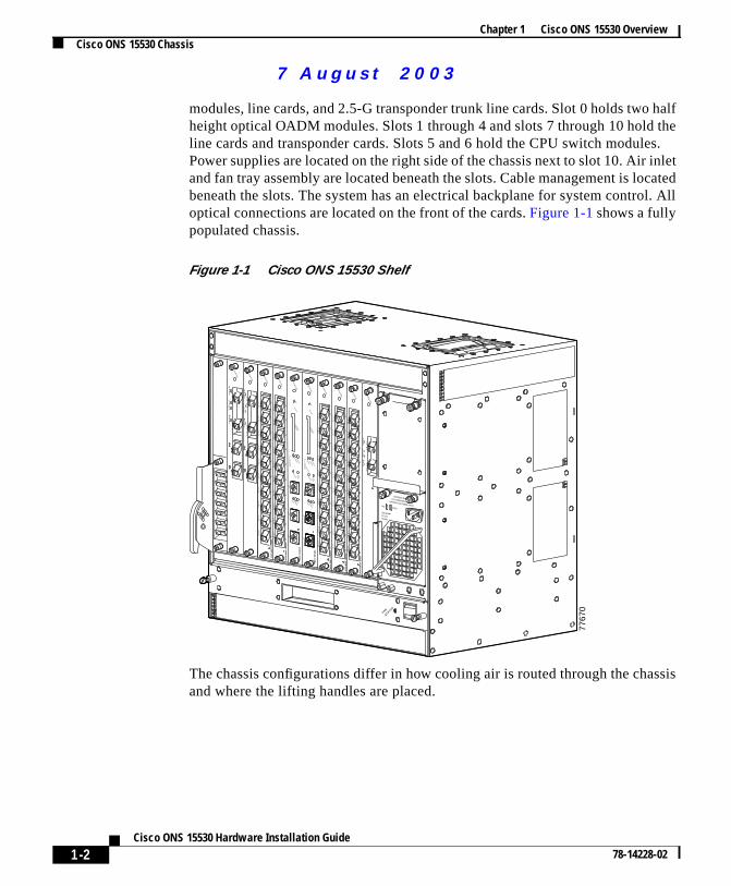
The dimensions of the Cisco ONS 15530 CHAS-E chassis are 14.4 x 17.3 x 1inches (H x W x D) SeeFigure 1-2. Handles for lifting the chassis are located onthe sides.
Figure 1-2 Cisco ONS 15530 CHAS-E Chassis
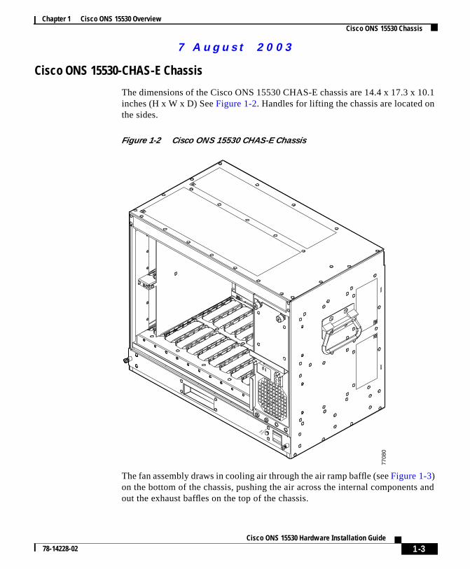
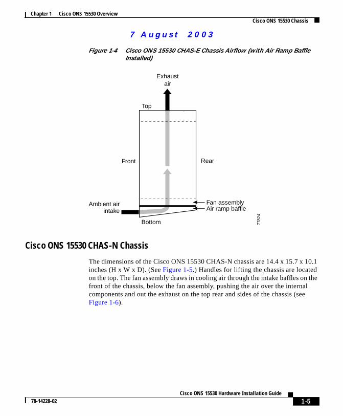
The fan assembly draws in cooling air through the air ramp baffle (seeFigure 1-3)on the bottom of the chassis, pushing the air across the internal componentout the exhaust baffles on the top of the chassis.
7708
0
FAN
STATUS
uals on ManualsBase.com
1-3Cisco ONS 15530 Hardware Installation Guide
78-14228-02
More user man
7 Augus t 20 03
Chapter 1 Cisco ONS 15530 OverviewCisco ONS 15530 Chassis
The air ramp baffle for the Cisco ONS 15530 CHAS-E chassis redirects thecooling air intake as shown inFigure 1-4. The air ramp baffle must be installedwhen installing the Cisco ONS 15530 CHAS-E type chassis.
Figure 1-3 Cisco ONS 15530 CHAS-E (with Air Ramp Baffle)
7782
5
FAN
STATUS
uals on ManualsBase.com
1-4Cisco ONS 15530 Hardware Installation Guide
78-14228-02
More user man
7 Augus t 20 03
Chapter 1 Cisco ONS 15530 OverviewCisco ONS 15530 Chassis
0.1
thel
ee
Figure 1-4 Cisco ONS 15530 CHAS-E Chassis Airflow (with Air Ramp BaffleInstalled)
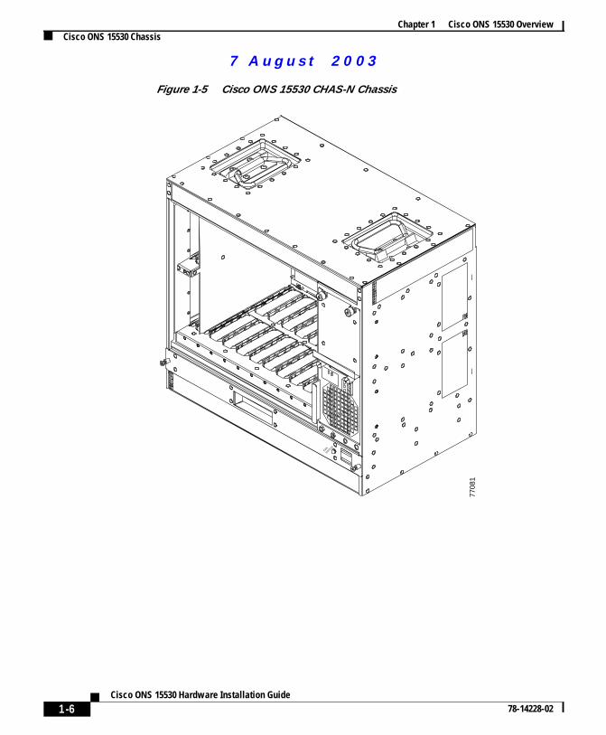
Cisco ONS 15530 CHAS-N Chassis
The dimensions of the Cisco ONS 15530 CHAS-N chassis are 14.4 x 15.7 x 1inches (H x W x D). (SeeFigure 1-5.) Handles for lifting the chassis are locatedon the top. The fan assembly draws in cooling air through the intake baffles onfront of the chassis, below the fan assembly, pushing the air over the internacomponents and out the exhaust on the top rear and sides of the chassis (sFigure 1-6).
Exhaustair
Ambient airintake
Fan assembly
Front Rear
Top
7782
4
Bottom
Air ramp baffle
uals on ManualsBase.com
1-5Cisco ONS 15530 Hardware Installation Guide
78-14228-02
More user man
7 Augus t 20 03
Chapter 1 Cisco ONS 15530 OverviewCisco ONS 15530 Chassis
Figure 1-5 Cisco ONS 15530 CHAS-N Chassis
7708
1
FAN
STATUS
uals on ManualsBase.com
1-6Cisco ONS 15530 Hardware Installation Guide
78-14228-02
More user man
7 Augus t 20 03
Chapter 1 Cisco ONS 15530 OverviewCisco ONS 15530 Chassis
The
o thePU
ges
he
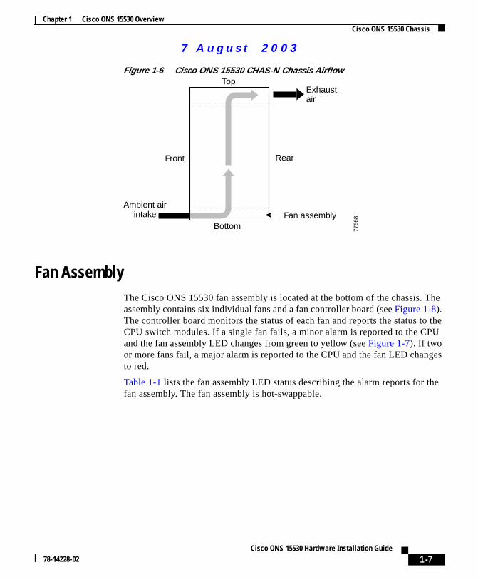
Figure 1-6 Cisco ONS 15530 CHAS-N Chassis Airflow
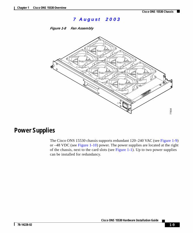
Fan AssemblyThe Cisco ONS 15530 fan assembly is located at the bottom of the chassis.assembly contains six individual fans and a fan controller board (seeFigure 1-8).The controller board monitors the status of each fan and reports the status tCPU switch modules. If a single fan fails, a minor alarm is reported to the Cand the fan assembly LED changes from green to yellow (seeFigure 1-7). If twoor more fans fail, a major alarm is reported to the CPU and the fan LED chanto red.
Table 1-1 lists the fan assembly LED status describing the alarm reports for tfan assembly. The fan assembly is hot-swappable.
Exhaustair
Ambient airintake
Front Rear
Top
7766
8
BottomFan assembly
uals on ManualsBase.com
1-7Cisco ONS 15530 Hardware Installation Guide
78-14228-02
More user man
7 Augus t 20 03
Chapter 1 Cisco ONS 15530 OverviewCisco ONS 15530 Chassis
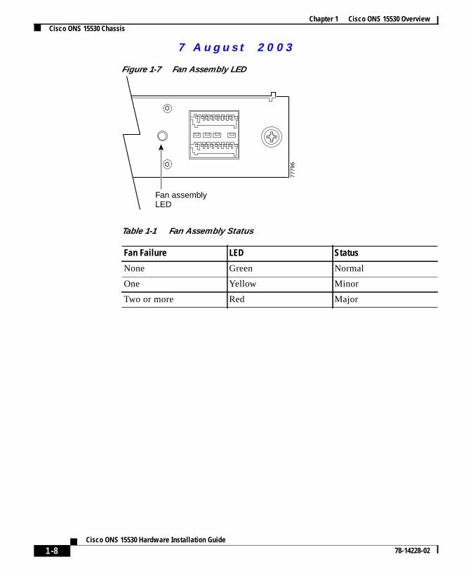
Figure 1-7 Fan Assembly LED
Fan assembly LED
7779
6
Table 1-1 Fan Assembly Status
Fan Failure LED Status
None Green Normal
One Yellow Minor
Two or more Red Major
uals on ManualsBase.com
1-8Cisco ONS 15530 Hardware Installation Guide
78-14228-02
More user man
7 Augus t 20 03
Chapter 1 Cisco ONS 15530 OverviewCisco ONS 15530 Chassis
t
Figure 1-8 Fan Assembly
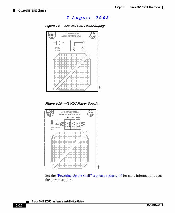
Power SuppliesThe Cisco ONS 15530 chassis supports redundant 120–240 VAC (seeFigure 1-9)or –48 VDC (seeFigure 1-10) power. The power supplies are located at the righof the chassis, next to the card slots (seeFigure 1-1). Up to two power suppliescan be installed for redundancy.
7783
4
FAN
STATUS
uals on ManualsBase.com
1-9Cisco ONS 15530 Hardware Installation Guide
78-14228-02
More user man
7 Augus t 20 03
Chapter 1 Cisco ONS 15530 OverviewCisco ONS 15530 Chassis
Figure 1-9 120–240 VAC Power Supply
Figure 1-10 –48 VDC Power Supply
See the“Powering Up the Shelf” section on page 2-47for more information aboutthe power supplies.
7789
4
FASTENERS MUST BEFULLY ENGAGED PRIOR TO
OPERATING THE POWER SUPPLY
100-240V ~8.0- 3.5A50-60 HZ
GOODFAIL
7789
3
FAIL
-48 TO -60V 17/A
GOOD
FASTENERS MUST BEFULLY ENGAGED PRIOR TO
OPERATING THE POWER SUPPLY
uals on ManualsBase.com
1-10Cisco ONS 15530 Hardware Installation Guide
78-14228-02
More user man
7 Augus t 20 03
Chapter 1 Cisco ONS 15530 OverviewCisco ONS 15530 Components
arens a
d
desheise
0:
BackplaneThe Cisco ONS 15530 backplane implements all board-to-board signalinterconnects and provides power distribution within the chassis. Connectionspresent for two power supplies and the fan assembly. The backplane contaitotal of 12 slots; two half-height slots for the OADM modules, two full heightslots for the CPU switch modules, and eight full height slots for line cards antransponder cards.
Cable Storage DrawerThe cable storage drawer is mounted directly below the fan assembly. It provistorage for the excess cable length. Sliding radius limiters move to release texcess fiber cable slack when the drawer is pulled out, allowing the user to rathe fiber routing tray and access the fan assembly.
Cisco ONS 15530 ComponentsThe following hardware components can be installed in the Cisco ONS 1553
• CPU Switch Modules, page 1-12
• OSC Modules and Carrier Motherboards, page 1-17
• PSM, page 1-18
• Transponder Line Cards, page 1-20
• Optical Add Drop Multiplexing Modules, page 1-25
• Wide-Band Variable Optical Attenuator and Per-Band Optical EqualizerModules, page 1-26
• ESCON Aggregation Cards, page 1-31
• 8-Port FC/GE Aggregation Cards, page 1-33
• 2.5-Gbps ITU Trunk Cards, page 1-36
• 10-Gbps ITU Trunk Cards, page 1-40
• 10-Gbps Uplink Cards, page 1-44
uals on ManualsBase.com
1-11Cisco ONS 15530 Hardware Installation Guide
78-14228-02
More user man
7 Augus t 20 03
Chapter 1 Cisco ONS 15530 OverviewCisco ONS 15530 Components
e inlledic, ahendhealss by
CPU Switch ModulesThe Cisco ONS 15530 supports two CPU switch modules for redundancy, onactive mode and the other in hot-standby mode. CPU switch modules are instain slot 5 and slot 6. Each CPU switch module has a processor, a switch fabrclock, an Ethernet switch for communication between processors and with tLRC (line card redundancy controller) on the OADM modules and line cards, aan SRC (switch card redundancy controller). The active processor controls tsystem. All LRCs in the system use the system clock and synchronization signfrom the active processor. Interfaces on the CPU switch modules permit acces10/100 Ethernet, console terminal, or modem connections.
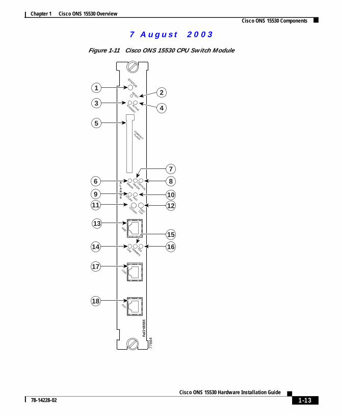
Figure 1-11 shows the front panel of the CPU switch module.
uals on ManualsBase.com
1-12Cisco ONS 15530 Hardware Installation Guide
78-14228-02
More user man
7 Augus t 20 03
Chapter 1 Cisco ONS 15530 OverviewCisco ONS 15530 Components
Figure 1-11 Cisco ONS 15530 CPU Switch Module
STATUS
RESET
ACTIVE
STANDBY
COMPACT
FLASH
CIRTICAL
MAJOR
AUX
NME
FDX100M
BPS
LINK
CON
CUTOFF
HISTCLR
CUTOFFHIST
MINOR
7766
4
15530-CP
U
ALARMS
1
3
5
6
9
11
17
18
13
7
8
12
14
15
16
10
4
2
uals on ManualsBase.com
1-13Cisco ONS 15530 Hardware Installation Guide
78-14228-02
More user man
7 Augus t 20 03
Chapter 1 Cisco ONS 15530 OverviewCisco ONS 15530 Components
on
CPU Switch Module Ports, LEDs, and Switches
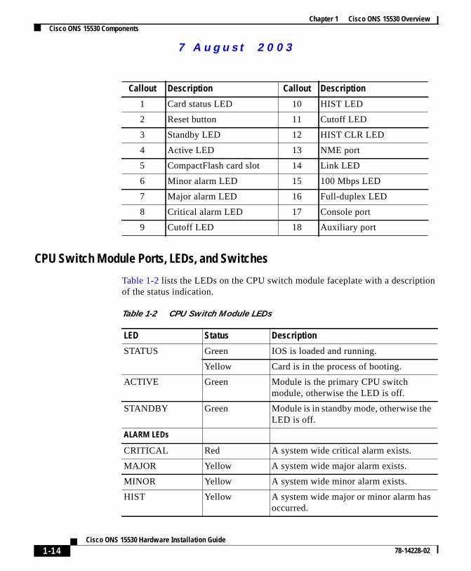
Table 1-2 lists the LEDs on the CPU switch module faceplate with a descriptiof the status indication.
Callout Description Callout Description
1 Card status LED 10 HIST LED
2 Reset button 11 Cutoff LED
3 Standby LED 12 HIST CLR LED
4 Active LED 13 NME port
5 CompactFlash card slot 14 Link LED
6 Minor alarm LED 15 100 Mbps LED
7 Major alarm LED 16 Full-duplex LED
8 Critical alarm LED 17 Console port
9 Cutoff LED 18 Auxiliary port
Table 1-2 CPU Switch Module LEDs
LED Status Description
STATUS Green IOS is loaded and running.
Yellow Card is in the process of booting.
ACTIVE Green Module is the primary CPU switchmodule, otherwise the LED is off.
STANDBY Green Module is in standby mode, otherwise theLED is off.
ALARM LEDs
CRITICAL Red A system wide critical alarm exists.
MAJOR Yellow A system wide major alarm exists.
MINOR Yellow A system wide minor alarm exists.
HIST Yellow A system wide major or minor alarm hasoccurred.
uals on ManualsBase.com
1-14Cisco ONS 15530 Hardware Installation Guide
78-14228-02
More user man
7 Augus t 20 03
Chapter 1 Cisco ONS 15530 OverviewCisco ONS 15530 Components
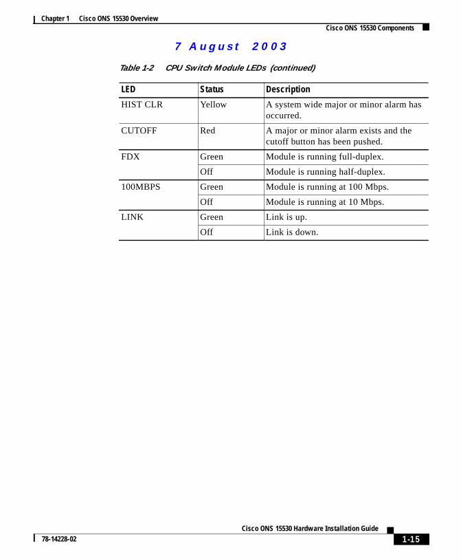
HIST CLR Yellow A system wide major or minor alarm hasoccurred.
CUTOFF Red A major or minor alarm exists and thecutoff button has been pushed.
FDX Green Module is running full-duplex.
Off Module is running half-duplex.
100MBPS Green Module is running at 100 Mbps.
Off Module is running at 10 Mbps.
LINK Green Link is up.
Off Link is down.
Table 1-2 CPU Switch Module LEDs (continued)
LED Status Description
uals on ManualsBase.com
1-15Cisco ONS 15530 Hardware Installation Guide
78-14228-02
More user man
7 Augus t 20 03
Chapter 1 Cisco ONS 15530 OverviewCisco ONS 15530 Components
the
ts
s
xtra
also
Connector Ports
The front panel on the CPU switch module contains three ports with RJ-45connectors (seeFigure 1-11):
• Network Management Ethernet port (NME)—This Ethernet port connectsCPU switch module to a 10/100BASE-T network management LAN.
• Console port (CON)—This asynchronous EIA/TIA-232 serial port conneca terminal to the CPU switch module for local administrative access.
• Auxiliary port (AUX)—This asynchronous EIA/TIA-232 serial port connecta modem to the CPU switch module for remote administrative access.
The RJ-45 connectors on the front panel of the CPU switch module have an eEMI shield and the signals going to them are filtered.Table 1-3shows the pinoutsof the console and auxiliary ports.
CompactFlash Card Slot
A CompactFlash card slot (seeFigure 1-11) can store the Cisco IOS image or asystem configuration file on a CompactFlash memory card. The system can boot from the software stored on the CompactFlash memory card.
Table 1-3 Console and Auxiliary Port RJ-45 Pinout
Pin# Console Auxiliary
Direction Function Direction Function
1 Output RTS Request To Send Output RTS Request To Send
2 Output DTR Data terminal ready Output DTR Data terminal ready
3 Output TxD Transmit data Output TxD Transmit data
4 N/A GND Ground N/A GND Ground
5 N/A GND Ground N/A GND Ground
6 Input RxD Receive data Input RxD Receive data
7 Input DSR Data set ready Input CD Carrier Detect
8 Input CTS Clear To Send Input CTS Clear To Send
uals on ManualsBase.com
1-16Cisco ONS 15530 Hardware Installation Guide
78-14228-02
More user man
7 Augus t 20 03
Chapter 1 Cisco ONS 15530 OverviewCisco ONS 15530 Components
andsingc toNS
rn.
elsnelsrop
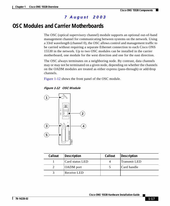
OSC Modules and Carrier MotherboardsThe OSC (optical supervisory channel) module supports an optional out-of-bmanagement channel for communicating between systems on the network. Ua 33rd wavelength (channel 0), the OSC allows control and management traffibe carried without requiring a separate Ethernet connection to each Cisco O15530 in the network. Up to two OSC modules can be installed in the carriemotherboard, one module for the west direction and one for the east directio
The OSC always terminates on a neighboring node. By contrast, data channmay or may not be terminated on a given node, depending on whether the chanon the OADM modules are treated as either express (pass-through) or add/dchannels.
Figure 1-12 shows the front panel of the OSC module.
Figure 1-12 OSC Module
Callout Description Callout Description
1 Card status LED 4 Transmit LED
2 OADM port 5 Card handle
3 Receive LED
STATUS
TXRX
7766
7
TX
RX
15530-OS
CM
1
3
5
4
2
uals on ManualsBase.com
1-17Cisco ONS 15530 Hardware Installation Guide
78-14228-02
More user man
7 Augus t 20 03
Chapter 1 Cisco ONS 15530 OverviewCisco ONS 15530 Components
s,
theItM theM
a
ivered
ssis.
r
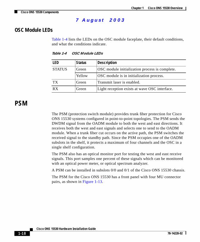
OSC Module LEDs
Table 1-4 lists the LEDs on the OSC module faceplate, their default conditionand what the conditions indicate.
PSMThe PSM (protection switch module) provides trunk fiber protection for CiscoONS 15530 systems configured in point-to-point topologies. The PSM sendsDWDM signal from the OADM module to both the west and east directions. receives both the west and east signals and selects one to send to the OADmodule. When a trunk fiber cut occurs on the active path, the PSM switchesreceived signal to the standby path. Since the PSM occupies one of the OADsubslots in the shelf, it protects a maximum of four channels and the OSC insingle shelf configuration.
The PSM also has an optical monitor port for testing the west and east recesignals. This port samples one percent of these signals which can be monitowith an optical power meter, or optical spectrum analyzer.
A PSM can be installed in subslots 0/0 and 0/1 of the Cisco ONS 15530 cha
The PSM for the Cisco ONS 15530 has a front panel with four MU connectopairs, as shown inFigure 1-13.
Table 1-4 OSC Module LEDs
LED Status Description
STATUS Green OSC module initialization process is complete.
Yellow OSC module is in initialization process.
TX Green Transmit laser is enabled.
RX Green Light reception exists at wave OSC interface.
uals on ManualsBase.com
1-18Cisco ONS 15530 Hardware Installation Guide
78-14228-02
More user man
7 Augus t 20 03
Chapter 1 Cisco ONS 15530 OverviewCisco ONS 15530 Components
Figure 1-13 PSM
8551
9
1
2
3
4
5
1 Rx/Tx West ports
2 Rx/Tx East ports
3 East/West LEDs
4 East/West Optical Monitorports
5 Common In/Out ports
uals on ManualsBase.com
1-19Cisco ONS 15530 Hardware Installation Guide
78-14228-02
More user man
7 Augus t 20 03
Chapter 1 Cisco ONS 15530 OverviewCisco ONS 15530 Components
at
rts a
one
der
gth
nd
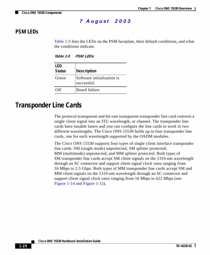
PSM LEDs
Table 1-5lists the LEDs on the PSM faceplate, their default conditions, and whthe conditions indicate.
Transponder Line CardsThe protocol-transparent and bit-rate transparent transponder line card convesingle client signal into an ITU wavelength, or channel. The transponder linecards have tunable lasers and you can configure the line cards to work in twdifferent wavelengths. The Cisco ONS 15530 holds up to four transponder licards, one for each wavelength supported by the OADM modules.
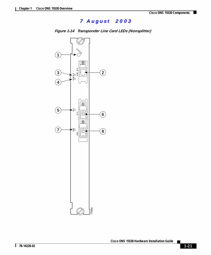
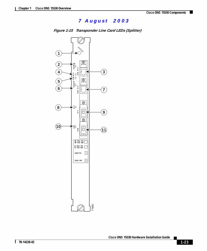
The Cisco ONS 15530 supports four types of single client interface transponline cards: SM (single mode) unprotected, SM splitter protected,MM (multimode) unprotected, and MM splitter protected. Both types ofSM transponder line cards accept SM client signals on the 1310-nm wavelenthrough an SC connector and support client signal clock rates ranging from16 Mbps to 2.5 Gbps. Both types of MM transponder line cards accept SM aMM client signals on the 1310-nm wavelength through an SC connector andsupport client signal clock rates ranging from 16 Mbps to 622 Mbps (seeFigure 1-14 andFigure 1-15).
Table 1-5 PSM LEDs
LEDStatus Description
Green Software initialization issuccessful.
Off Board failure.
uals on ManualsBase.com
1-20Cisco ONS 15530 Hardware Installation Guide
78-14228-02
More user man
7 Augus t 20 03
Chapter 1 Cisco ONS 15530 OverviewCisco ONS 15530 Components
Figure 1-14 Transponder Line Card LEDs (Nonsplitter)
STATUS
7765
9
TX
TX
TX
RX
RX
RX
TX
RX
1
5
7
4
2
6
8
3
uals on ManualsBase.com
1-21Cisco ONS 15530 Hardware Installation Guide
78-14228-02
More user man
7 Augus t 20 03
Chapter 1 Cisco ONS 15530 OverviewCisco ONS 15530 Components
Callout Description Callout Description
1 Card status LED 5 Client side transmit LED
2 ITU side port 6 Client side transmit port
3 ITU transmit LED 7 Client side receive LED
4 ITU receive LED 8 Client side receive port
uals on ManualsBase.com
1-22Cisco ONS 15530 Hardware Installation Guide
78-14228-02
More user man
7 Augus t 20 03
Chapter 1 Cisco ONS 15530 OverviewCisco ONS 15530 Components
Figure 1-15 Transponder Line Card LEDs (Splitter)
STATUS
7766
0
TX
TX
TX
EAST
WEST
RX
TX
RX
RX
RX
TX
RX
1
2
6
8
10
3
7
9
11
5
4
W ITU TXW ITU RX
E ITU TXE ITU RX
1310 TX
1310 RX
uals on ManualsBase.com
1-23Cisco ONS 15530 Hardware Installation Guide
78-14228-02
More user man
7 Augus t 20 03
Chapter 1 Cisco ONS 15530 OverviewCisco ONS 15530 Components
andape,nt
pe
on
.
The transponder line cards are hot swappable, permitting in-service upgradesreplacement. All client signals on the transponders are supported in 3R (reshretime, retransmit) mode, regardless of protocol encapsulation type. The clieinterfaces also support the OFC (open fiber control) safety protocol for FibreChannel, ISC compatibility mode, and FICON. The client side ports use SC-tyconnectors.
On the trunk side, the transponder line card output laser power ranges from5 to 10 dBm and the receive detector has a sensitivity of –32 dBm. The portsthe trunk side use MU-type connectors.
Transponder Line Card LEDs
Table 1-6 lists the LEDs on the transponder line card faceplate, their defaultconditions, and what the conditions indicate.
Callout Description Callout Description
1 Card status LED 7 East side ITU port
2 West side ITU LED 8 Client side transmit LED
3 West side ITU port 9 Client side transmit port
4 ITU side transmit LED 10 Client side receive LED
5 ITU side receive LED 11 Client side receive port
6 East side ITU LED
Table 1-6 Transponder Line Card LEDs
LED Status Description
STATUS Green Card is properly initialized.
Blinking green Good system clock is present and card isout of reset state.
Yellow System clock is not present.
EAST1 Green Card is listening to the east side signal.
TX (Trunk port) Green Port is up and transmit laser is enabled
uals on ManualsBase.com
1-24Cisco ONS 15530 Hardware Installation Guide
78-14228-02
More user man
7 Augus t 20 03
Chapter 1 Cisco ONS 15530 OverviewCisco ONS 15530 Components
lextheode
re are
hensnkm
.
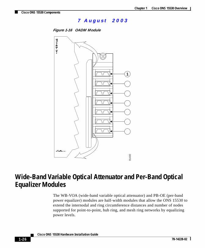
Optical Add Drop Multiplexing ModulesThe OADM modules are passive devices that optically multiplex and demultipa specific band of four ITU wavelengths. The OADM modules supported by Cisco ONS 15530 each add and drop a specified band of four channels at a nand pass the other bands through. To support the 32-channel spectrum, theeight different 4-channel cards (seeFigure 1-16).
In the transmit direction, the OADM modules multiplex signals transmitted by ttransponder line cards and 10G ITU trunk cards over optical cross connectioand provide the interfaces to connect the multiplexed signal to the DWDM truside. In the receive direction, the OADM modules demultiplex the signals frothe trunk side before passing them over optical cross connections to thetransponder line cards and 10G ITU trunk cards.
RX (Trunk port) Green Light reception exists at the port.
WEST1 Green Card is listening to the west side signal.
TX (Client port) Green Port is up and transmit laser is enabled
RX (Client port) Green Light reception exists at the port.
1. This LED is only present on transponder line cards with splitter.
Table 1-6 Transponder Line Card LEDs (continued)
LED Status Description
uals on ManualsBase.com
1-25Cisco ONS 15530 Hardware Installation Guide
78-14228-02
More user man
7 Augus t 20 03
Chapter 1 Cisco ONS 15530 OverviewCisco ONS 15530 Components
tos
Figure 1-16 OADM Module
Wide-Band Variable Optical Attenuator and Per-Band OpticalEqualizer Modules
The WB-VOA (wide-band variable optical attenuator) and PB-OE (per-bandpower equalizer) modules are half-width modules that allow the ONS 15530extend the internodal and ring circumference distances and number of nodesupported for point-to-point, hub ring, and mesh ring networks by equalizingpower levels.
9140
0
1
2
3
4
5
6
7
uals on ManualsBase.com
1-26Cisco ONS 15530 Hardware Installation Guide
78-14228-02
More user man
7 Augus t 20 03
Chapter 1 Cisco ONS 15530 OverviewCisco ONS 15530 Components
l
The
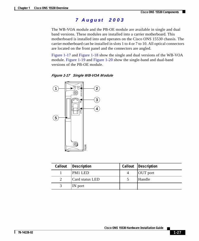
The WB-VOA module and the PB-OE module are available in single and duaband versions. These modules are installed into acarrier motherboard. Thismotherboard is installed into and operates on the Cisco ONS 15530 chassis.carrier motherboard can beinstalled in slots 1 to 4 or 7 to 10. All optical connectorsare located on the front panel and the connectors are angled.
Figure 1-17 andFigure 1-18 show the single and dual versions of the WB-VOAmodule.Figure 1-19 andFigure 1-20 show the single-band and dual-bandversions of the PB-OE module.
Figure 1-17 Single WB-VOA Module
7916
6
2
3
4
PM1 STA
15500-VO
A-0100
INO
UT
1
5
Callout Description Callout Description
1 PM1 LED 4 OUT port
2 Card status LED 5 Handle
3 IN port
uals on ManualsBase.com
1-27Cisco ONS 15530 Hardware Installation Guide
78-14228-02
More user man
7 Augus t 20 03
Chapter 1 Cisco ONS 15530 OverviewCisco ONS 15530 Components
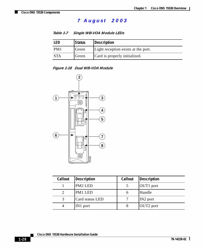
Figure 1-18 Dual WB-VOA Module
Table 1-7 Single WB-VOA Module LEDs
LED Status Description
PM1 Green Light reception exists at the port.
STA Green Card is properly initialized.
7916
8
PM1PM2 STA
15500-VO
A-0200
IN1
OU
T1
IN2
OU
T2
3
4
5
2
7
8
1
6
Callout Description Callout Description
1 PM2 LED 5 OUT1 port
2 PM1 LED 6 Handle
3 Card status LED 7 IN2 port
4 IN1 port 8 OUT2 port
uals on ManualsBase.com
1-28Cisco ONS 15530 Hardware Installation Guide
78-14228-02
More user man
7 Augus t 20 03
Chapter 1 Cisco ONS 15530 OverviewCisco ONS 15530 Components
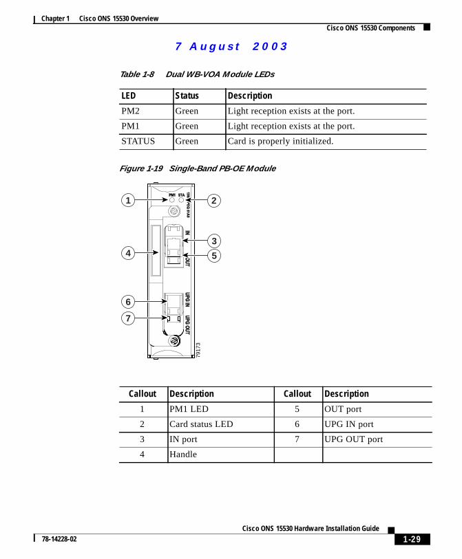
Figure 1-19 Single-Band PB-OE Module
Table 1-8 Dual WB-VOA Module LEDs
LED Status Description
PM2 Green Light reception exists at the port.
PM1 Green Light reception exists at the port.
STATUS Green Card is properly initialized.
7917
3
4
6
7
1
3
5
2
Callout Description Callout Description
1 PM1 LED 5 OUT port
2 Card status LED 6 UPG IN port
3 IN port 7 UPG OUT port
4 Handle
uals on ManualsBase.com
1-29Cisco ONS 15530 Hardware Installation Guide
78-14228-02
More user man
7 Augus t 20 03
Chapter 1 Cisco ONS 15530 OverviewCisco ONS 15530 Components
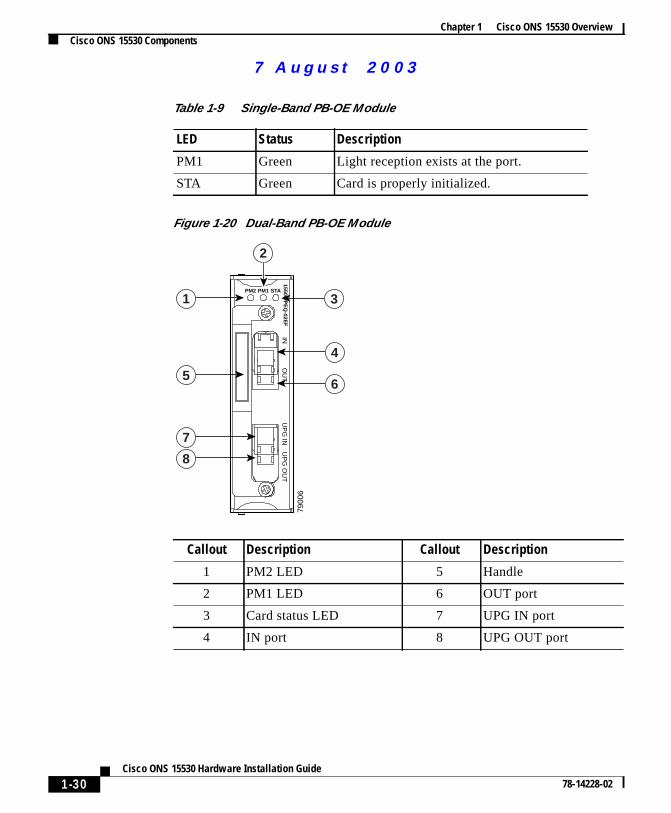
Figure 1-20 Dual-Band PB-OE Module
Table 1-9 Single-Band PB-OE Module
LED Status Description
PM1 Green Light reception exists at the port.
STA Green Card is properly initialized.
Callout Description Callout Description
1 PM2 LED 5 Handle
2 PM1 LED 6 OUT port
3 Card status LED 7 UPG IN port
4 IN port 8 UPG OUT port
7900
6
5
7
8
1
2
4
6
3PM2 PM1 STA
15500-PE
Q-02E
FIN
OU
TU
PG
INU
PG
OU
T
uals on ManualsBase.com
1-30Cisco ONS 15530 Hardware Installation Guide
78-14228-02
More user man
7 Augus t 20 03
Chapter 1 Cisco ONS 15530 OverviewCisco ONS 15530 Components
emsal
to
he
ithals.
ctly
psne
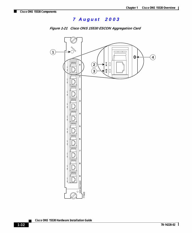
ESCON Aggregation CardsThe ESCON aggregation card is a 10-port card for ESCON (Enterprise SystConnection) traffic. The ESCON card converts the 10 client signals from opticto electrical and then aggregates them into a single 2.5-Gbps signal. Thisaggregated signal is sent through the backplane and the active switch fabriceither a 10G ITU trunk card or a 10-Gbps uplink card. The cross connectionbetween the two cards is configured using the CLI (command-line interface). TESCON aggregation card has a redundant backplane connection.
The ESCON aggregation card uses multi-mode 62.5/125 um optical cable wSFPs (small form factor pluggables) and MT-RJ connectors for the client sign(SeeFigure 1-21.)
Note The SFPs (part number 15500-XVRA-01A2 ONS 15530 ESCON-1310nmMM-MTRJ) must be purchased separately.
Note A patch cable to adapt MT-RJ connectors to standard ESCON connectors direor intermediately to SC-type connectors may be required.
This signal is sent through the switch fabric to a 10G ITU trunk card or a 10-Gbuplink card. The 10Gbps ITU trunk card converts the aggregated signal to aITU-compliant wavelength, or channel. The 10-Gbps uplink card converts thaggregated signal to transmit to another shelf.
Table 1-10 Dual-Band PB-OE LEDs
LED Status Description
PM2 Green Light reception exists at the port.
PM1 Green Light reception exists at the port.
STATUS Green Card is properly initialized.
uals on ManualsBase.com
1-31Cisco ONS 15530 Hardware Installation Guide
78-14228-02
More user man
7 Augus t 20 03
Chapter 1 Cisco ONS 15530 OverviewCisco ONS 15530 Components
Figure 1-21 Cisco ONS 15530 ESCON Aggregation Card
STATUS
7766
3
TX
RX
TX
RX
TX
RX
TX
RX
TX
RX
TX
RX
TX
RX
TX
RX
TX
RX
TX
RX
15
53
0-L
CM
B-0
20
0
0
1
2
3
4
5
6
7
8
9
1
TX
RX
0
2
3
4
uals on ManualsBase.com
1-32Cisco ONS 15530 Hardware Installation Guide
78-14228-02
More user man
7 Augus t 20 03
Chapter 1 Cisco ONS 15530 OverviewCisco ONS 15530 Components
l)
for isals
ctiveorthe
h
f
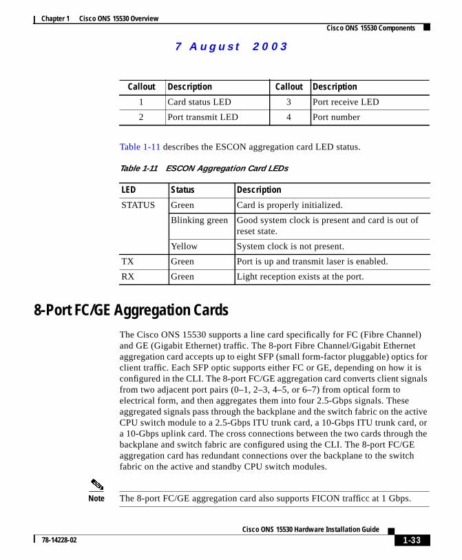
Table 1-11 describes the ESCON aggregation card LED status.
8-Port FC/GE Aggregation CardsThe Cisco ONS 15530 supports a line card specifically for FC (Fibre Channeand GE (Gigabit Ethernet) traffic. The 8-port Fibre Channel/Gigabit Ethernetaggregation card accepts up to eight SFP (small form-factor pluggable) opticsclient traffic. Each SFP optic supports either FC or GE, depending on how itconfigured in the CLI. The 8-port FC/GE aggregation card converts client signfrom two adjacent port pairs (0–1, 2–3, 4–5, or 6–7) from optical form toelectrical form, and then aggregates them into four 2.5-Gbps signals. Theseaggregated signals pass through the backplane and the switch fabric on the aCPU switch module to a 2.5-Gbps ITU trunk card, a 10-Gbps ITU trunk card,a 10-Gbps uplink card. The cross connections between the two cards throughbackplane and switch fabric are configured using the CLI. The 8-port FC/GEaggregation card has redundant connections over the backplane to the switcfabric on the active and standby CPU switch modules.
Note The 8-port FC/GE aggregation card also supports FICON trafficc at 1 Gbps.
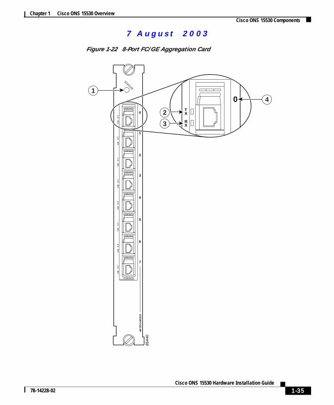
Callout Description Callout Description
1 Card status LED 3 Port receive LED
2 Port transmit LED 4 Port number
Table 1-11 ESCON Aggregation Card LEDs
LED Status Description
STATUS Green Card is properly initialized.
Blinking green Good system clock is present and card is out oreset state.
Yellow System clock is not present.
TX Green Port is up and transmit laser is enabled.
RX Green Light reception exists at the port.
uals on ManualsBase.com
1-33Cisco ONS 15530 Hardware Installation Guide
78-14228-02
More user man
7 Augus t 20 03
Chapter 1 Cisco ONS 15530 OverviewCisco ONS 15530 Components
ticsithFP
r a
Note We strongly recommend configuring port pairs as FC only or GE only. MixingFC and GE in a port pair increases the FC signal latency between nodes.
The 8-port FC/GE aggregation card uses single-mode and multimode SFP opfor the client signals. There are no restrictions on populating the line card wSFPs. For example, you can mix a single-mode SFP optic with a multimode Soptic in the same port pair.Table 1-12lists features for the SFP optics supportedby the 8-port FC/GE aggregation card.
The Cisco ONS 15530 supports up to four 8-port FC/GE aggregation cards fototal of 32 client signals.
Table 1-12 8-Port FC/GE aggregation card SFP Optics Features
Part Number Supported Protocols Fiber Type WavelengthConnectorType
15500-XVRA-02C1 Gigabit Ethernet1, FibreChannel (1 Gbps)2
1. 1000BaseSX
2. FC-0-100-M5-SN-S and FC-0-100-M6-SN-S standards
MM 50/125 mMM 62.5/125 m
850 nm Duplex LC
15500-XVRA-03B1 Gigabit Ethernet3, FibreChannel (1 Gbps)4
3. 1000BaseLX
4. FC-0-100-SM-LC-S standard
SM 9/125 m 1310 nm Duplex LC
uals on ManualsBase.com
1-34Cisco ONS 15530 Hardware Installation Guide
78-14228-02
More user man
7 Augus t 20 03
Chapter 1 Cisco ONS 15530 OverviewCisco ONS 15530 Components
Figure 1-22 8-Port FC/GE Aggregation Card
8544
0
STATUS
TX
RX
TX
RX
TX
RX
TX
RX
TX
RX
TX
RX
TX
RX
TX
RX
15
53
0F
CG
E-8
P
0
1
2
3
4
5
6
7
1
TX
RX
0
2
3
4
uals on ManualsBase.com
1-35Cisco ONS 15530 Hardware Installation Guide
78-14228-02
More user man
7 Augus t 20 03
Chapter 1 Cisco ONS 15530 OverviewCisco ONS 15530 Components
nalneort
ane,les.ent
fest
tch
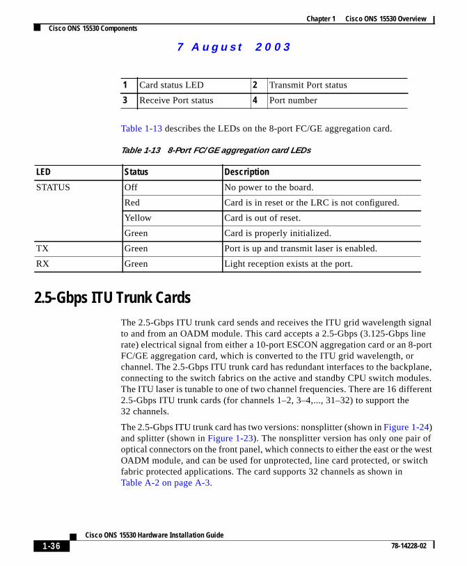
Table 1-13 describes the LEDs on the 8-port FC/GE aggregation card.
2.5-Gbps ITU Trunk CardsThe 2.5-Gbps ITU trunk card sends and receives the ITU grid wavelength sigto and from an OADM module. This card accepts a 2.5-Gbps (3.125-Gbps lirate) electrical signal from either a 10-port ESCON aggregation card or an 8-pFC/GE aggregation card, which is converted to the ITU grid wavelength, orchannel. The 2.5-Gbps ITU trunk card has redundant interfaces to the backplconnecting to the switch fabrics on the active and standby CPU switch moduThe ITU laser is tunable to one of two channel frequencies. There are 16 differ2.5-Gbps ITU trunk cards (for channels 1–2, 3–4,..., 31–32) to support the32 channels.
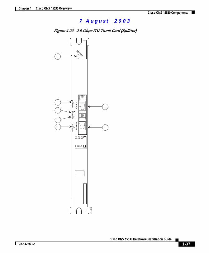
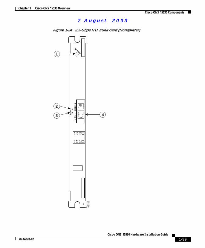
The 2.5-Gbps ITU trunk card has two versions: nonsplitter (shown inFigure 1-24)and splitter (shown inFigure 1-23). The nonsplitter version has only one pair ooptical connectors on the front panel, which connects to either the east or the wOADM module, and can be used for unprotected, line card protected, or swifabric protected applications. The card supports 32 channels as shown inTable A-2 on page A-3.
1 Card status LED 2 Transmit Port status
3 Receive Port status 4 Port number
Table 1-13 8-Port FC/GE aggregation card LEDs
LED Status Description
STATUS Off No power to the board.
Red Card is in reset or the LRC is not configured.
Yellow Card is out of reset.
Green Card is properly initialized.
TX Green Port is up and transmit laser is enabled.
RX Green Light reception exists at the port.
uals on ManualsBase.com
1-36Cisco ONS 15530 Hardware Installation Guide
78-14228-02
More user man
7 Augus t 20 03
Chapter 1 Cisco ONS 15530 OverviewCisco ONS 15530 Components
Figure 1-23 2.5-Gbps ITU Trunk Card (Splitter)
9150
4
TXRX
TXRX
TX
WEST
EAST
E ITU TXE ITU RX
W ITU TXW ITU RX
RX
STATUS1
2
6
3
7
5
4
uals on ManualsBase.com
1-37Cisco ONS 15530 Hardware Installation Guide
78-14228-02
More user man
7 Augus t 20 03
Chapter 1 Cisco ONS 15530 OverviewCisco ONS 15530 Components
1 Card status LED 5 Receive LED
2 West side port LED 6 East side port LED
3 West side port 7 East side port
4 Transmit LED
uals on ManualsBase.com
1-38Cisco ONS 15530 Hardware Installation Guide
78-14228-02
More user man
7 Augus t 20 03
Chapter 1 Cisco ONS 15530 OverviewCisco ONS 15530 Components
Figure 1-24 2.5-Gbps ITU Trunk Card (Nonsplitter)
8531
5
TXRX
TXRX T
X
E ITU TXE ITU RX
W ITU TXW ITU RX
RX
STATUS1
43
2
uals on ManualsBase.com
1-39Cisco ONS 15530 Hardware Installation Guide
78-14228-02
More user man
7 Augus t 20 03
Chapter 1 Cisco ONS 15530 OverviewCisco ONS 15530 Components
nal
nbps
bpshles.
l,for
ofDM
l of
Table 1-14 lists and describes the 2.5-Gbps ITU Trunk Card LEDs.
10-Gbps ITU Trunk CardsThe 10-Gbps ITU trunk card sends and receives the ITU grid wavelength sigto and from an OADM module. This card accepts up to four 2.5-Gbps(3.125-Gbps line rate) electrical signals from the 10-port ESCON aggregatiocards and 8-port FC/GE aggregation cards, and combines them into one 10-Gsignal, which is converted to the ITU grid wavelength, or channel. The 10-GITU trunk card has four separate redundant interfaces to the backplane, eacconnecting to the switch fabrics on the active and standby CPU switch modu
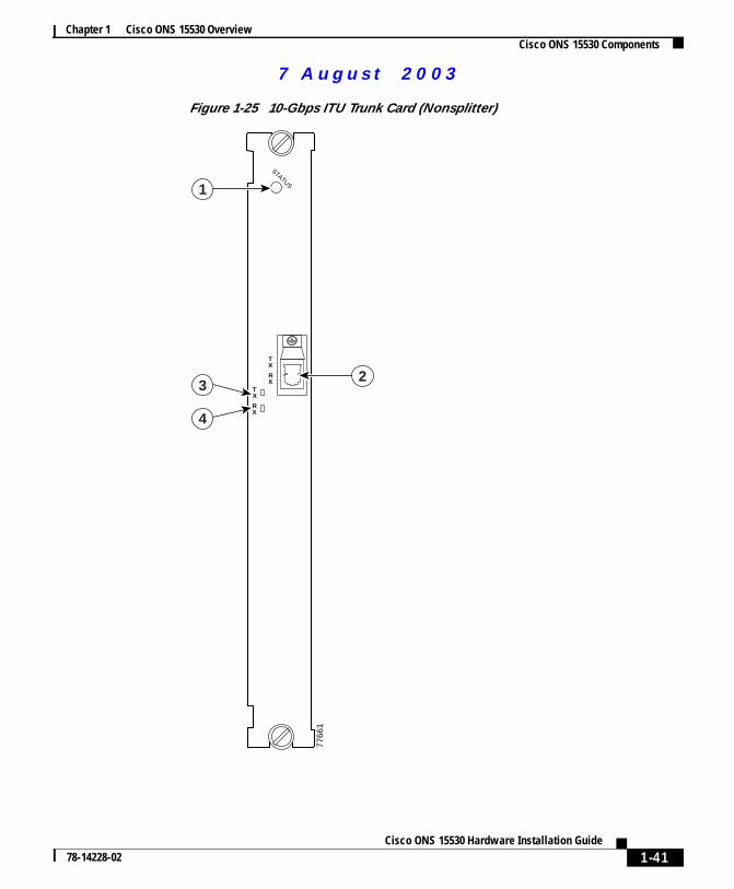
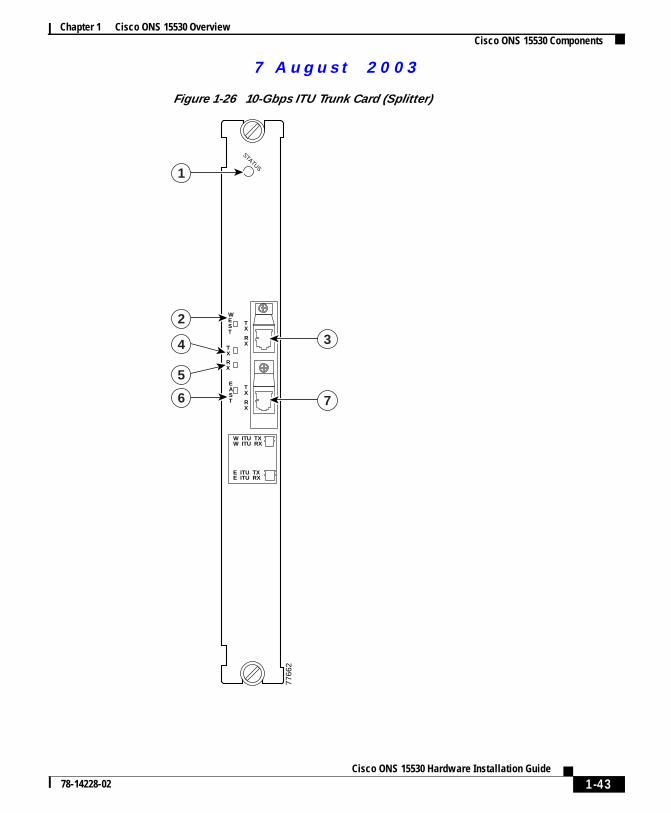
The 10-Gbps ITU trunk card has two versions: nonsplitter and splitter. Thenonsplitter version has only one pair of optical connectors on the front panewhich connects to either the east or the west OADM module, and can be usedunprotected, line card protected, or switch fabric protected applications (seeFigure 1-25). The splitter version of the 10-Gbps ITU trunk card has two pairsoptical connectors on the front panel, which connect to the east and west OAmodules, and is designed for splitter protected applications (seeFigure 1-26).
The Cisco ONS 15530 supports up to four 10-Gbps ITU trunk cards for a totafour channels.
1 Card status LED 2 Transmit LED
3 Receive LED 4 Transmit/Receive port
Table 1-14 2.5-Gbps ITU Trunk Card LEDs
LED Status Description
STATUS Green Card is properly initialized.
WEST Green Card is listening to the west side signal.
TX Green Port is up and transmit laser is enabled.
RX Green Light reception exists at the port.
EAST Green Card is listening to the east side signal.
uals on ManualsBase.com
1-40Cisco ONS 15530 Hardware Installation Guide
78-14228-02
More user man
7 Augus t 20 03
Chapter 1 Cisco ONS 15530 OverviewCisco ONS 15530 Components
Figure 1-25 10-Gbps ITU Trunk Card (Nonsplitter)
STATUS
7766
1
TX
TX
RX
RX
1
2
4
3
uals on ManualsBase.com
1-41Cisco ONS 15530 Hardware Installation Guide
78-14228-02
More user man
7 Augus t 20 03
Chapter 1 Cisco ONS 15530 OverviewCisco ONS 15530 Components
1 Card status LED 3 Transmit LED
2 ITU port 4 Receive LED
uals on ManualsBase.com
1-42Cisco ONS 15530 Hardware Installation Guide
78-14228-02
More user man
7 Augus t 20 03
Chapter 1 Cisco ONS 15530 OverviewCisco ONS 15530 Components
Figure 1-26 10-Gbps ITU Trunk Card (Splitter)
STATUS
7766
2
TX
TX
EAST
WEST
RX
TX
RX
RX
1
2
6
3
7
5
4
W ITU TXW ITU RX
E ITU TXE ITU RX
uals on ManualsBase.com
1-43Cisco ONS 15530 Hardware Installation Guide
78-14228-02
More user man
7 Augus t 20 03
Chapter 1 Cisco ONS 15530 OverviewCisco ONS 15530 Components
30,
lane.itch
sed
SP
Table 1-15 describes the10-Gbps ITU trunk card LED status.
10-Gbps Uplink CardsThe 10-Gbps uplink card, shown inFigure 1-27, sends and receives a 10-GE1310-nm signal to and from a 10-GE uplink card on another Cisco ONS 155or to and from a 10-GE transponder module on a Cisco ONS 15540 ESP orCisco ONS 15540 ESPx. This card accepts up to four (3.125-Gbps line rate)electrical signals from 10-port ESCON aggregation cards and 8-port FC/GEaggregation cards, and combines them into one 10-GE signal.
The 10-Gbps uplink card has four separate redundant interfaces to the backpEach interface connects to the switch fabric on the active and standby CPU swmodules.
The 10-Gbps uplink card has only one version: nonsplitter. The nonsplitterversion has only one pair of optical connectors on the front panel and can be ufor unprotected or line card protected applications. For splitter protectedconfigurations, the splitter line card motherboards on the Cisco ONS 15540 Eand the Cisco ONS 15540 ESPx provide the facility protection.
1 Card status LED 5 Receive LED
2 West side port LED 6 East side port LED
3 West side port 7 East side port
4 Transmit LED
Table 1-15 10-Gbps ITU Trunk Card LEDs
LED Status Description
STATUS Green Card is properly initialized.
WEST Green Card is listening to the west side signal.
TX Green Port is up and transmit laser is enabled.
RX Green Light reception exists at the port.
EAST Green Card is listening to the east side signal.
uals on ManualsBase.com
1-44Cisco ONS 15530 Hardware Installation Guide
78-14228-02
More user man
7 Augus t 20 03
Chapter 1 Cisco ONS 15530 OverviewCisco ONS 15530 Components
ur
The Cisco ONS 15530 supports up to four 10-Gbps uplink cards for a total of fosignals.uals on ManualsBase.com
1-45Cisco ONS 15530 Hardware Installation Guide
78-14228-02
More user man
7 Augus t 20 03
Chapter 1 Cisco ONS 15530 OverviewCisco ONS 15530 Components
Figure 1-27 10-Gbps Uplink Card
TX
RX
TX
RX
STATUS
15530-10GE
-UP
LINK
7766
5
1
23
45
uals on ManualsBase.com
1-46Cisco ONS 15530 Hardware Installation Guide
78-14228-02
More user man
7 Augus t 20 03
Chapter 1 Cisco ONS 15530 OverviewCisco ONS 15530 Components
Table 1-16 describes the 10-Gbps uplink line card LED status.
Table 1-16 10-Gbps Uplink Line Card LEDs
LED Status Description
STATUS Green Card is properly initialized.
TX Green Port is up and transmit laser is enabled.
RX Green Light reception exists at the port.
uals on ManualsBase.com
1-47Cisco ONS 15530 Hardware Installation Guide
78-14228-02

7 Augus t 20 03
Chapter 1 Cisco ONS 15530 OverviewCisco ONS 15530 Components
1-48Cisco ONS 15530 Hardware Installation Guide
78-14228-02