Embed Size (px)
Citation preview

Documents contained herein supersede all previously published versions.
City of Auburn Public Works Department
171 N. Ross Street, Suite 200 Auburn, Alabama 36830
334 501 3000 334 501 7294 (fax)
City of Auburn Standard Construction Specifications
As Revised January 1, 2016

This page intentionally left blank.

CITY OF AUBURN STANDARD SPECIFICATIONS TABLE OF CONTENTS
GENERAL CONDITIONS
SECTION 1
DEFINITION OF TERMS Purpose ..................................................................................................................................... 1.01 Interpretation ........................................................................................................................... 1.02 Abbreviations ............................................................................................................................ 1.03 Terms Defined ........................................................................................................................... 1.04 SECTION 2
PROPOSAL REQUIREMENTS AND CONDITIONS Qualifications of Bidders ........................................................................................................... 2.01 Contents of Proposal Forms...................................................................................................... 2.02 Interpretation of Approximate Estimates ................................................................................. 2.03 Examination of Contract Documents and Site of Work ............................................................ 2.04 Preparation of Proposal ............................................................................................................ 2.05 Rejection of Proposals .............................................................................................................. 2.06 Withdrawal or Revision of Proposal ......................................................................................... 2.07 Disqualification of Bidders ........................................................................................................ 2.08
SECTION 3
INSURANCE, HOLD HARMLESS, AND CONTRACT BONDS Insurance and Hold Harmless ................................................................................................... 3.01 Contract Bonds.......................................................................................................................... 3.02
SECTION 4
SCOPE OF WORK Intent of Contract Documents .................................................................................................. 4.01 Alteration of Drawings or Character of Work ........................................................................... 4.02 Extra Work ................................................................................................................................ 4.03 Traffic Control ........................................................................................................................... 4.04 Construction and Maintenance of Detours .............................................................................. 4.05 Removal and Disposal of Structures and Obstructions ............................................................ 4.06 Final Clean Up ........................................................................................................................... 4.07 Maintenance of the Work During Construction ....................................................................... 4.08

City of Auburn Standard Specifications Table of Contents Page 2
Updated: January 1, 2016
Failure to Maintain Roads or Structures ................................................................................... 4.09
SECTION 5
CONTROL OF WORK Authority of Engineer ................................................................................................................ 5.01 Working Drawings ..................................................................................................................... 5.02 Conformity with Documents and Allowable Deviations ........................................................... 5.03 Coordination of Drawings, Specifications, and Special Provisions ........................................... 5.04 Cooperation of the Contractor ................................................................................................. 5.05 Representatives ........................................................................................................................ 5.06 Review ....................................................................................................................................... 5.07 Removal of Defective and Unauthorized Work ........................................................................ 5.08 Correction of Work ................................................................................................................... 5.09 Dispute Claims .......................................................................................................................... 5.10 Final Construction Review ........................................................................................................ 5.11 Final Acceptance ....................................................................................................................... 5.12 SECTION 6
CONTROL OF MATERIAL Source of Supply and Quality of Materials ............................................................................... 6.01 Samples and Tests ..................................................................................................................... 6.02 Storage of Materials.................................................................................................................. 6.03 Defective Materials ................................................................................................................... 6.04 Testing Cost ............................................................................................................................... 6.05 SECTION 7
LEGAL RELATIONS AND RESPONSIBILITY TO PUBLIC Public Convenience and Safety ................................................................................................. 7.01 Crossing Railroads ..................................................................................................................... 7.02 Barricades, Danger, Warning and Detour Signs........................................................................ 7.03 Preservation & Restoration of Property, Trees, and Monuments ........................................... 7.04 Accident Reporting ................................................................................................................... 7.05 Right-of-Way ............................................................................................................................. 7.06 Interference of Contractors ...................................................................................................... 7.07 Contractors Responsibility for Work ......................................................................................... 7.08 Personal Liability of Public Officials .......................................................................................... 7.09 No Waiver of Legal Rights ......................................................................................................... 7.10
City of Auburn Standard Specifications Table of Contents Page 3
Updated: January 1, 2016
SECTION 8
PROSECUTION AND PROGRESS Subletting or Assigning of Contract .......................................................................................... 8.01 Prosecution of Work ................................................................................................................. 8.02 Limitations of Operations ......................................................................................................... 8.03 Character of Workmen and Equipment .................................................................................... 8.04 Temporary Suspension of Work ............................................................................................... 8.05 Determination of Contract Time ............................................................................................... 8.06 Extension of Contract Time ....................................................................................................... 8.07 Failure or Delay in Completing Work on Time .......................................................................... 8.08 Default of Contract ................................................................................................................... 8.09 Extra and Force Account Work ................................................................................................. 8.10 SECTION 9
TESTING/TESTING MATERIALS General ...................................................................................................................................... 9.01 Responsibility ............................................................................................................................ 9.02 Testing Requirements ............................................................................................................... 9.03
STANDARD SPECIFICATIONS
SECTION 10
STREETS General .................................................................................................................................... 10.01 Testing Responsibility ............................................................................................................. 10.02 Contractor Responsibility ........................................................................................................ 10.03 Subgrade Preparation ............................................................................................................. 10.04 Bases ....................................................................................................................................... 10.05 Surfacing and Pavement ........................................................................................................ 10.06 Concrete .................................................................................................................................. 10.07 Seeding and Sodding ............................................................................................................... 10.08 Underdrain .............................................................................................................................. 10.09

City of Auburn Standard Specifications Table of Contents Page 4
Updated: January 1, 2016
SECTION 11
CONCRETE General .................................................................................................................................... 11.01 Testing Responsibility ............................................................................................................. 11.02 Contractor Responsibility ........................................................................................................ 11.03 Classes of Concrete ................................................................................................................. 11.04 Materials ................................................................................................................................. 11.05 Construction Methods ............................................................................................................ 11.06 Finishing Concrete................................................................................................................... 11.07 Reinforcing Steel ..................................................................................................................... 11.08
SECTION 12
SANITARY SEWER SYSTEMS General .................................................................................................................................... 12.01 Testing Responsibility ............................................................................................................. 12.02 Contractor Responsibility ........................................................................................................ 12.03 Excavation and Backfilling ....................................................................................................... 12.04 Pipe ......................................................................................................................................... 12.05 Construction Methods ............................................................................................................ 12.06 Manholes ................................................................................................................................ 12.07 Lift Stations ............................................................................................................................. 12.08 Testing ..................................................................................................................................... 12.09
SECTION 13
EXCAVATION AND BACKFILL General .................................................................................................................................... 13.01 Testing Responsibility ............................................................................................................. 13.02 Contractor Responsibility ........................................................................................................ 13.03 Site Work ................................................................................................................................. 13.04 Types of Excavation ................................................................................................................ 13.05 Construction Methods ............................................................................................................ 13.06
SECTION 14
WATER MAINS AND APPURTENANCES General .................................................................................................................................... 14.01 Testing Responsibility ............................................................................................................. 14.02

City of Auburn Standard Specifications Table of Contents Page 5
Updated: January 1, 2016
Contractor Responsibility ........................................................................................................ 14.03 Materials ................................................................................................................................. 14.04 Valves ...................................................................................................................................... 14.05 Pressure Regulators ............................................................................................................... 14.06 Pressure Gauges ..................................................................................................................... 14.07 Fire Hydrants ........................................................................................................................... 14.08 Services ................................................................................................................................... 14.09 Meters .................................................................................................................................... 14.10 Construction Methods ........................................................................................................... 14.11 Testing ..................................................................................................................................... 14.12 Maintenance ........................................................................................................................... 14.13
SECTION 15
GRASSING General .................................................................................................................................... 15.01 Testing Responsibility ............................................................................................................................ 15.02 ....................................................................................................................................................... Contractor Responsibility ........................................................................................................ 15.03 Construction Methods ............................................................................................................ 15.04 Grass Bond .............................................................................................................................. 15.05 SECTION 16
STORM SEWER SYTEMS General .................................................................................................................................... 16.01 Testing Responsibility ............................................................................................................. 16.02 Contractor Responsibility ........................................................................................................ 16.03 Excavation and Backfilling ....................................................................................................... 16.04 Culverts ................................................................................................................................... 16.05 Inlets and Junction Boxes ........................................................................................................ 16.06 Headwalls ................................................................................................................................ 16.07 Ditches .................................................................................................................................... 16.08 Plugging and Removal of Existing Pipe and Structures........................................................... 16.09

This page intentionally left blank.
CITY OF AUBURN STANDARD SPECIFICATIONS GENERAL CONDITIONS
SECTION 1
DEFINITIONS OF TERMS
A. Purpose Whenever in these Contract Documents the following terms or pronouns in the place of them appear, their intent and meaning shall be interpreted as identified below. In the event that a term is not listed in this document, the conventional meaning of such term shall apply. B. Interpretation The City Engineer of the City of Auburn is hereby authorized to make a final determination of any term used in these regulations. C. Abbreviations
AASHTO American Association of State Highway and Transportation Officials ALDOT Alabama Department of Transportation ANSI American National Standards Institute ASTM American Society for Testing and Materials AWWB Auburn Water Works Board FHWA Federal Highway Administration M.U.T.C.D. Manual on Uniform Traffic Control Devices
D. Terms Defined Bidder. Any individual, firm, partnership, corporation or any acceptable combination thereof submitting a Bid for the advertised work. Calendar Day. Every day shown on the calendar, beginning and ending at midnight, Sundays and holidays included. City. The term “City” used in these Specifications refers to the City of Auburn, Auburn Water Works Board, and Auburn Industrial Development Board. Contract Bonds. The approved bonds furnished by the Contractor and his Surety to guarantee completion of the Contract in accordance with its terms. Contract Document. The written agreement between the City and the Contractor setting forth the obligations of the parties hereunder for the performance of the prescribed work. The Contract shall include the Invitation to Bid, Instructions to Bidders, Proposal, Proposal Bond, Base Bid, the Contract, Performance Bond, Labor and Materials Payment Bond, the Specifications, Special Conditions, addenda, general and detailed plans, and Notice to Proceed, as well as any change orders, supplemental agreements and authorized extensions required to complete the work in a substantial and acceptable manner.
City of Auburn Standard Specifications Section 1
Page 2
General Conditions Updated: January 1, 2016
Contractor. The individual, partnership, firm, or corporation that has entered into a Contract awarded by the City for the work covered by this contract. County. Lee County Drawings. All officially approved plans, which are on file with the City, or exact reproductions thereof, showing alignment, layout and design of structures, profiles, typical cross-sections, accessory features, and particular location, character, dimensions, and details of the Work covered by the Contract. Engineer. The company or person designated by the City, acting within the scope of authority and/or the particular duties entrusted to him. Equipment. All machinery, together with the necessary supplies for upkeep and maintenance, and all tools and apparatus necessary for the proper construction and acceptable completion of the Work. Extra Work. Work or material, the performance or furnishing of which is found necessary for proper completion of the improvement and, which in principle is an obligation of the Contractor, but which is not covered by any item in the bid schedule in the Proposal and for which no means of payment, direct or indirect, has been provided in the Contract, and which is an obligation for which special remuneration by an "Extra" price or by other consideration, in any case to be duly negotiated, or by "Force Account," shall be paid to the Contractor. Extra Work Orders. Written orders signed by the Engineer to the Contractor concerning the performance of work and furnishing of materials involving Extra Work as defined in these Specifications. Force Account. Payment to the Contractor on a per hour basis. Rate per hour includes a percentage of profit agreed upon by the City and Contractor. The rate per hour also includes allowances for machinery, fuel, payroll, benefits of the Contractor's employees, overhead, general, and administrative expenses. Labor and Materials Payment Bond. The bond posted for the work guaranteeing payment for materials and labor contained in the work, valued at 100% of the contract amount. Laboratory. Any laboratory approved by the Engineer and authorized by the City to test materials

City of Auburn Standard Specifications Section 1
Page 3
General Conditions Updated: January 1, 2016
and work involved in the Contract. Legal Holiday. Holidays which will be allowed in computing Contractor’s time charges on a working day basis will be limited to the following days: Sundays, New Year’s Day, Robert E. Lee’s/Martin Luther King birthday (3rd Monday in January), National Memorial Day, Independence Day, Labor Day, Veterans Day, Thanksgiving Day and Christmas Day. Material. Any substance proposed to be used in connection with the construction of any part of the work and its appurtenances. Notice to Proceed. Written notice from the Engineer giving the Contractor the date on which he is to begin the prosecution of the Work. Plans. See Drawings Project Manager/Inspector. An authorized representative of the City or Engineer, assigned to review any or all portions of materials furnished and work performed by the Contractor. Proposal. The written offer for the Work, when submitted by the Bidder in the required manner on the prescribed Proposal Form properly signed and guaranteed. Proposal Form. The approved prepared form on which the City requires that formal bids be submitted for the Work. Proposal Guaranty. The certified check, cashier's check or Proposal Bond designated in the Instructions to Bidders to be furnished by the Bidder to guarantee execution of the Contract and furnishing of the bonds for the work contemplated, if it is awarded to him. Retainage. Money belonging to the Contractor which has been retained by the awarding authority conditioned on final completion and acceptance of all work in connection with a project or projects by the Contractor. Shop Drawings. Fabrication plans for any part of the work including, but not limited to, water and sanitary mains and appurtenances, precast concrete items, structural steel items, or other metal items, and connections thereof, which the Contractor is required to submit to the Engineer. Specifications. Written technical and other requirements for the Work, prepared by or on behalf of the City, which are on file with the City, containing directions, provisions, and technical and

City of Auburn Standard Specifications Section 1
Page 4
General Conditions Updated: January 1, 2016
general requirements for the Work, together with such as may be added as Supplemental Specifications or Provisions. Standard Drawings. Drawings approved for repetitive use, showing details to be used where appropriate. Standard Specifications. A book of specifications approved for general application and repetitive use. State. The State of Alabama. Subcontractor. Any properly qualified individual, firm, or corporation undertaking the performance of any part of the Work under the terms of the Contract, by virtue of any agreement between himself and the Contractor. Superintendent. The representative for the Contractor who shall be present on the Work at all times during progress, authorized to receive and fulfill instructions from the Engineer and capable of efficiently superintending the Work. Supplemental Agreement/Change Order. A written agreement executed by the City and the Contractor covering major changes and/or revision or new unit prices and items supplementing or modifying the original Contract. Surety. The corporate body, licensed under the laws of the State, bound with and for the Contractor for the acceptable performance of the Contract, and also, for the payment of claims recoverable under the Contract Bonds. Work (The Work). All performance required of the Contractor under the terms of the Contract. Working Day. Any Calendar day, exclusive of Saturdays and legal holidays on which the Contractor could proceed with construction operations for a period of six (6) hours or more with the normal working forces engaged in performing work on the controlling item or items of work, which normally would be in progress at that time, will be classified as a working day. Saturdays and legal holidays on which the Contractor elects to work for a period of four (4) hours or more will be classified as a working day.
City of Auburn Standard Specifications Section 1
Page 5
General Conditions Updated: January 1, 2016
Working Drawings. Erection plans, false work plans, framework plans, cofferdam plans, or any other supplementary plans or similar data, which the Contractor is required to submit to the Engineer.

This page intentionally left blank.
CITY OF AUBURN STANDARD SPECIFICATIONS
GENERAL CONDITIONS
SECTION 2 PROPOSAL REQUIREMENTS AND CONDITIONS
2.01 QUALIFICATIONS OF BIDDERS Prospective Bidders must be able to show that they are capable of performing each of the various items of work upon which they bid, and that the equipment necessary for the prosecution of the Work is available. The Bidder shall be licensed as a Contractor as required by State law. 2.02 CONTENTS OF PROPOSAL FORMS The City will furnish Bidders specifications containing a blank Proposal Form showing a description of the Work contemplated, the approximate estimate of the various quantities of the pay items of the work to be performed and materials to be furnished, the amount of the Proposal Guaranty, and the date, time, and place of opening of Proposals and the time in which the Work must be completed. All papers bound with or attached to the Proposal Form are a necessary part thereof and must not be detached or altered. 2.03 INTERPRETATION OF APPROXIMATE ESTIMATES Although the estimate of quantities of work listed in the Proposal Form are the results of calculations made from field surveys, they are to be considered as only approximate estimates of the quantities of the different pay items and are to be used only as a basis for comparing bids for awarding the Contract. Such quantities, including the classification thereof, may or may not be representative of the actual conditions encountered during construction and the City does not represent that the estimated quantities given will accord with actual quantities encountered in the construction of the Work. Final payment to the Contractor will be made for only the actual quantities of the respective pay items of the Work performed, at the contract unit prices bid in the Proposal, in accordance with the Contract Document, as finally determined from actual measurements made during the progress or after completion of the Work, and if, upon completion of the Work, the actual quantities of the respective pay items performed be more or less than the quantities estimated in the Proposal, the contract unit prices bid in the Proposal will still prevail, except as otherwise hereinafter provided. 2.04 EXAMINATION OF CONTRACT DOCUMENTS AND SITE OF WORK All Bidders are required to examine carefully the site of the proposed Work and Contract and it is mutually agreed that the submission of a Proposal shall be prima fascia evidence that the
City of Auburn Standard Specifications Section 2
Page 2
General Conditions Updated: January 1, 2016
Bidder has made such examination and has judged for and satisfied himself as to the conditions to be encountered and as to the character, quality, and quantities of work to be performed and materials to be furnished. Bidders shall also familiarize themselves with and shall comply with the requirements of all Federal, State, and Local Laws and Ordinances which may directly or indirectly affect the Work, prosecution of the Work, persons engaged in or employed on the Work, or the materials or equipment used in the Work. No adjustments or compensations will be allowed for losses caused by failure to comply with the above requirements. 2.05 PREPARATION OF PROPOSAL The Bidder's Proposal must be submitted on the Proposal Form furnished him by the City. The Bidder shall not modify or alter the Proposal Form provided by the City. The Bidder must specify, with figures, a unit price for each of the separate items for which a quantity is given in the Proposal Form (except where alternate bids are called for on items). He shall show the products of the respective unit prices and the estimated quantities in the columns provided for that purpose, as well as the gross sum for which he will perform all the estimated work as required by the Contract Documents. The Engineer will check the gross sum obtained by adding the products of the unit prices and the various estimated quantities listed in the Proposal and this shall be the Contract Bid Price. The Bidder shall properly sign the Proposal. 2.06 REJECTION OF PROPOSALS The City reserves the right to reject any or all Proposals. Proposals may be rejected for any reason, including, but not limited to, omissions, alterations of form, additions not called for, conditional bids, alternate bids unless called for, incomplete bids, erasures and irregularities of any kind. 2.07 WITHDRAWAL OR REVISION OF PROPOSAL A Proposal may be withdrawn at any time prior to the hour fixed in the Invitation to Bid for opening of Proposals, provided a request in writing executed by the Bidder or his duly authorized representative is filed with the City prior to that time. When such Proposal is received, it will be returned to the Bidder unopened. No Proposal can be withdrawn, modified, or corrected after the hour set for opening such Proposals.

City of Auburn Standard Specifications Section 2
Page 3
General Conditions Updated: January 1, 2016
2.08 DISQUALIFICATION OF BIDDERS If there is reason to believe that collusion exists among the Bidders, any or all Proposals may be rejected, and participants in such collusion may not be considered in future Proposals for the same work.

This page intentionally left blank.
CITY OF AUBURN STANDARD SPECIFICATIONS
GENERAL CONDITIONS SECTION 3
INSURANCE, HOLD HARMLESS, AND CONTRACT BONDS 3.01 INSURANCE AND HOLD HARMLESS The Contractor will be required to provide certificates of insurance showing that it carries, or has in force, automobile liability insurance, general liability insurance and workers’ compensation insurance. Limits of liability for automobile liability insurance shall be, at a minimum, $1,000,000.00 combined single limit. Limits of liability for general liability insurance shall be, at a minimum, $1,000,000.00 per occurrence, $1,000,000.00 personal and advertising injury, $1,000,000.00 general aggregate and $1,000,000.00 products/completed operations aggregate. General liability insurance will include coverage for contractually assumed liability. If the general liability insurance is written on a claims-made basis, the Contractor will maintain coverage in force for a period of two (2) years following the termination of the contract at the limits specified in this paragraph. Workers’ compensation insurance shall provide statutory workers’ compensation coverage and employers’ liability coverage with limits of, at a minimum, $500,000.00 each accident, $500,000.00 disease – each employee and $500,000.00 accident, $500,000.00 disease – policy limit. The Contractor is responsible for the payment of any deductibles or self-insured retentions. The Contractor’s insurance will be primary. If the Contractor carries higher coverage limits, the higher coverage limits will apply. The City will be named as additional insured under the Contractor’s general liability insurance and automobile liability insurance policies. The Contractor shall require certificates of insurance from sub-contractors. Sub-contractors will carry limits of insurance equal to or greater than those carried by the Contractor. These certificates shall evidence waivers of subrogation in favor of the City and the Contractor and shall be made available to the City upon request. The Contractor agrees to indemnify, hold harmless, and defend the City, its officials, representatives, agents, servants, and employees from and against any and all claims, actions, lawsuits, damages, judgments, liability and expense, including attorneys fees and litigation expenses, in whole or in part arising out of, connected with, or in any way associated with the activities of the Contractor, its employees, or its sub-contractors in connection with the work to be performed under this contract. This obligation survives the payment of any loss by the Contractor’s insurance carrier. This contract may not be assigned by the Contractor without the written permission of the City. This contract will be interpreted according to the laws of the State of Alabama. Legal action arising from the performance of this contract will be filed in the Circuit Court of Lee County, Alabama located in Opelika, Alabama or the Federal District Court for the Middle District of Alabama – Eastern Division located in Opelika, Alabama.
City of Auburn Standard Specifications Section 3
Page 2
General Conditions Updated: January 1, 2016
3.02 CONTRACT BONDS Within ten (10) days after Notice of Award, the successful Bidder shall furnish and file with the City a performance bond and a labor and material payment bond, in such form as required by this Contract and in an amount not less than 100% of the Contract Bid Price.
CITY OF AUBURN STANDARD SPECIFICATIONS
GENERAL CONDITIONS
SECTION 4 SCOPE OF WORK
4.01 INTENT OF CONTRACT DOCUMENTS The intent of the Contract is to include all items necessary for the proper execution and completion of the Work by the Contractor. The Contract is complementary, and what is required by one portion of the Contract shall be required by all. Performance by the Contractor shall be required only to the extent consistent with the Contract Documents and reasonably inferable from them as being necessary to produce the intended results. 4.02 ALTERATION OF DRAWINGS OR CHARACTER OF WORK The Engineer may, without notice to the Surety and without change in the unit prices, make alterations in the Drawings or in the nature of the Work which he may consider necessary or desirable during the progress of the Work to complete fully and acceptably the proposed construction, provided that such alterations do not materially change the general features of the original Contract. Material changes shall be understood to mean those changes in the original Contract made necessary by the exigencies of the Work resulting in the alteration of costs to the Contractor by an amount, which could not have been foreseen at the time of this bidding upon the Work. The City reserves the right for the Engineer to revise any part of the alignment, grades, structures, width, and other dimensions on the Work, if the Engineer deems it advisable and such changes shall not be considered material changes. The City also reserves the right for the Engineer to increase or decrease the quantity of any or all of the items listed in the estimate of approximate quantities in the Proposal Form and such increase or decrease shall not be considered as a waiver of any of the conditions of the Contract or Contract Bonds. 4.03 EXTRA WORK In connection with the Work covered by this Contract, the Engineer may at any time during progress of the Work order other work or materials incidental thereto. If any such work and material is not listed as a pay item with a contract unit bid price or if compensation therefore is not included in the contract unit prices bid for other items under the terms of the Contract, such work will be designated as Extra Work, and shall be performed by the Contractor as directed, provided, however, that before any Extra Work is started the Engineer shall furnish the Contractor a Proposal Form, stating the location, kind, and estimated quantities of the Extra Work to be done. The Contractor shall indicate on this Proposal Form the compensation (unit price or lump sum) for which he will perform the Extra Work and this proposal shall be submitted to the City for approval. The City may approve the proposal, in which case it shall be an authorization for doing the Extra Work and shall become a part of the Contract, but if the City considers the price submitted for any item of the Extra Work excessive and a satisfactory adjustment price cannot be reached for such item, it shall be optional with the City to terminate the Contract in so far as it applies to such item

City of Auburn Standard Specifications Section 4
Page 2
General Conditions Updated: January 1, 2016
or Extra Work in question and perform such item or Extra Work by other agents or other means or to direct that the Contractor perform the work on a "Force Account" basis. The City may reject claims for payment for Extra Work not so authorized. Extra Work shall be done under the supervision of the Engineer and his decision shall be final and binding. The plan of the work to be followed, the equipment to be used, and the amount and character of labor to be employed shall meet with his approval. 4.04 TRAFFIC CONTROL All traffic control devices shall conform to the MUTCD, latest edition. All required traffic control measures must be installed and approved by the City of Auburn prior to any construction activities. All traffic control measures must have reflectivity as outlined in the ALDOT Specifications. The City of Auburn reserves the right to reject any items with incorrect reflectivity and placement and deny payment of the same. If the Contractor fails to install and maintain proper traffic control measures, the City of Auburn reserves the right to immediately stop work, at no cost to the City, until such measures are installed properly. 4.05 CONSTRUCTION AND MAINTENANCE OF DETOURS No road or section of road shall be closed to traffic except with the written permission of the Engineer and no construction operations that will in any way inconvenience the traveling public shall be started until adequate provisions have been made to detour or by-pass traffic in safety and comfort. The Contractor shall give at least 48 hours notice of an anticipated road closure to the Project Manager, unless an emergency arises. The Contractor shall maintain all detours over the Work. Unless otherwise provided in the Special Conditions, the road, which is undergoing improvement, shall, except at times when deemed impractical by the Engineer, be kept continuously open to public traffic and in passable and safe condition. When the Contractor hauls materials over any detour or public road, he shall so regulate his loads that the capacity of the road and its structures or the Alabama Department of Transportation load limits, whichever is less, are not exceeded and he shall be responsible for any specific damage that may result to the road or its structures from failure to observe regulations governing traffic thereon.

City of Auburn Standard Specifications Section 4
Page 3
General Conditions Updated: January 1, 2016
4.06 REMOVAL AND DISPOSAL OF STRUCTURES AND OBSTRUCTIONS Unless otherwise provided, the Contractor shall remove at his expense any existing structure or part of a structure, fence, building, or other encumbrance or obstruction upon or within the limits of the Work, which interfere in any way with the new construction. Compensation for the removal of any structure shown on the Drawings shall be as indicated in the Contract. 4.07 FINAL CLEAN UP Upon completion and before work will be finally accepted and final payment made, the Contractor shall clean and remove from the Work and adjacent property, stream channels, sites of structures, and all areas occupied by him in connection with the Work, all weeds, shrubs, stumps, or portions of trees, and all loose rock, boulders, false work, temporary structures, machinery and equipment. He shall restore in an acceptable manner all property, both public and private, which has been damaged during the prosecution of the Work, and shall leave the Work and sites of structures, in a neat presentable condition throughout the project. Clearing material from the right-of-way and depositing it on abutting property with or without the consent of the property owner will not be considered a satisfactory method of disposal. 4.08 MAINTENANCE OF THE WORK DURING CONSTRUCTION The Contractor will be required to maintain the Work from the date of the approval of his Contract until the entire Contract is completed and shall maintain for thirty- (30) days after it is completed. The maintenance shall consist of continuous and effective work prosecuted day by day with adequate equipment and forces to the end of keeping the road and structures in satisfactory and acceptable condition at all times. The Contractor shall take adequate precautions to protect trees, shrubs, and plants from injury during construction operations. This shall include, but is not limited to, barrier fencing for tree protection, erosion and sediment control measures, etc. In addition, the Contractor shall on a daily basis remove excess debris, materials, etc. from the construction site. Compensation for the maintenance work during construction and before the work is finally accepted shall be included in the contract unit prices bid on the pay items of the work and the City will not pay additional for such work.
City of Auburn Standard Specifications Section 4
Page 4
General Conditions Updated: January 1, 2016
4.09 FAILURE TO MAINTAIN ROADS OR STRUCTURES The failure of the Contractor, at any time, to comply with the above provisions for Maintenance of the Work (Section 4.07) will result in the following:
1. The Engineer will immediately notify the Contractor, his superintendent or employees to comply with the required maintenance provisions.
2. In the event the Contractor fails to remedy his lack of or unsatisfactory maintenance
within one (1) day after the date of issuance of this notice, the City will proceed immediately with adequate forces and equipment to maintain in a satisfactory and acceptable manner the road, or structures, and the entire cost of this maintenance will be deducted from monies due or that become due the Contractor on this Contract, or any other contract the Contractor may have with the City.
3. As an alternate to the City's taking over the maintenance, all the quantities of the
Work performed which are not properly maintained may be deducted from the current estimate even if such quantities have been allowed on a previous estimate.
CITY OF AUBURN STANDARD SPECIFICATIONS GENERAL CONDITIONS
SECTION 5
CONTROL OF WORK
5.01 AUTHORITY OF THE ENGINEER To prevent misunderstandings, disputes, and litigation, the Engineer shall decide any and all questions that arise concerning the quality and acceptability of materials furnished and work performed, the manner of performance and rate of progress of the Work, interpretation of the Drawings and Specifications, and the acceptable fulfillment of the Contract on the part of the Contractor. The Engineer will determine the amount, quantity, character, classification, and quality of the several kinds of work performed and materials furnished which are to be paid for under the Contract and his decision and estimate shall be conclusive and binding on both parties thereto and such decision and estimate of the Engineer, in case any questions arise, shall be a condition precedent to the right of the Contractor to receive any money due him under the Contract. Explanations concerning the meaning of the Contract and all directions necessary to complete or make definite the Contract and to give them due effect, will be given by the Engineer and his findings shall be final and binding on both parties hereto. The Engineer shall have executive authority to enforce and make effective such decisions and orders. He shall decide upon disputes and mutual rights between Contractors under the Drawings and Specifications. The existence of a dispute shall not excuse the Contractor from performing under this Contract, and the Contractor shall diligently and consistently perform and prosecute the Work pending resolution of all disputes. 5.02 WORKING DRAWINGS Drawings showing such details as are necessary to give a general intent of the construction contemplated will be included in the Contract. The Contractor shall be responsible for supplementing the Contract by such working drawings as are necessary to adequately control the Work. It is mutually agreed that all authorized alterations affecting the requirements and information given in the Contract shall be given by the Engineer in writing. It is expressly understood that the approval by the Engineer of the Contractor's working drawings shall not constitute or authorize changed work, Extra Work or deviation from the Contract and that such approval relates solely to the requirements for strength and detail and such approval will not relieve the Contractor of any responsibility for accuracy of dimensions and details, or of mutual agreement of dimensions or details. It is mutually agreed that the Contractor shall be responsible for agreement and conformity of his working drawings with the Contract. The Contractor shall furnish the Engineer with such blue print copies of the working drawings as may be required for approval and construction purposes and upon completion of the Work, the original tracings or satisfactory negatives thereof shall be supplied to the Engineer. Such drawings shall be furnished by the Contractor without additional compensation.
City of Auburn Standard Specifications Section 5
Page 2
General Conditions Updated: January 1, 2016
5.03 CONFORMITY WITH CONTRACT DOCUMENTS Finished work in all cases shall conform to lines, grades, sections, details, and dimensions of the Work contemplated as shown on the approved Contract Documents except as modified by written orders of the Engineer. Any deviation from the Contract that may be required by the exigencies of the construction must be approved in advance by the Engineer and authorized in writing. 5.04 COORDINATION OF DRAWINGS, SPECIFICATIONS, AND SPECIAL PROVISION The Specifications, the Supplemental Specifications, the Drawings, Special Conditions, and all supplementary documents are essential parts of the Contract, and a requirement occurring in one is as binding as though occurring in all. They are intended to be complementary and to describe and provide for a complete Work. In case of discrepancy, figured dimensions, unless obviously incorrect, shall govern over scaled dimensions. Supplemental Specifications shall govern over the Standard Specifications. Drawings shall govern over Specifications; Special Conditions shall govern over both Specifications and Drawings. The Contractor shall take no advantage of, and shall promptly notify the Engineer, if he discovers any error or omission of dimensions in the Drawings, or of any discrepancy between the Drawings and Specifications. The Engineer will make such corrections and supply such omitted dimensions. The Engineer's interpretation shall be final. 5.05 COOPERATION OF THE CONTRACTOR The Contractor will be supplied with two (2) copies of the Contract Documents, unless otherwise requested. In no instance shall any more than five (5) copies of the [contract] be given to the Contractor without additional cost being incurred. The Contractor shall have available on the work site, at all times, a copy of the contract. He shall give the Work the constant attention necessary to facilitate the progress thereof and shall cooperate with the Engineer or his representative and with other Contractors in every way possible. The Contractor shall at all times have a competent Superintendent on the Work site, capable of reading and thoroughly understanding the contract, as his agent on the Work, with full authority to execute the orders or directions of the Engineer without delay and to supply promptly such materials, tools, equipment, and labor as may be required. Such Superintendent shall be furnished irrespective of the amount of work sub-let and shall have full authority over all sub-contract work.
City of Auburn Standard Specifications Section 5
Page 3
General Conditions Updated: January 1, 2016
The Contractor shall schedule and conduct his work and dispose of his material so as to avoid causing unnecessary inconvenience and delay to other Contractors engaged on adjacent work and so as to join his work to that of other Contractors in a proper manner, and in accordance with the spirit of the contract, and so as to perform his work in the proper sequence in relation to that of other adjacent work, all as may be directed by the Engineer. Each Contractor shall so conduct his operation and maintain the work in such condition that adequate drainage shall be provided at all times. It is mutually agreed that in case of a dispute arising between two or more Contractors engaged on the same work, as to the respective rights of each under these contract the Engineer shall determine the matter at issue and shall cause completion of all parts of the Work and his decision shall be final and binding on all parties concerned and shall not in any way be a cause for claims for extra compensation by any of the parties. 5.06 REPRESENTATIVES The Engineer may appoint such Representatives as he desires, and they shall be granted full access to the Work and to mills and factories in which material is being prepared for use under the Contract. They shall have authority to give directions pertaining to the Work, to approve or reject materials, to make measurements of quantities, to keep records of costs, and otherwise to represent the Engineer. The Contractor may appeal their decisions to the Engineer, pending settlement but no work shall be done in disregard of orders or instruction on items affected by such appeal. If the Contractor refuses to comply with instruction of the Representative to fulfill the requirements of the Contract, the Representative, shall if possible, immediately notify his immediate superior and obtain instructions, failing in this, if the Contractor refuses to suspend operations on verbal order, he shall issue a written order suspending the Work on the items affected, giving in detail the reasons for the suspension and immediately after placing the order in the hands of the person in charge for the Contractor, he shall report to his immediate superior, or in his absence to the Engineer, for further instructions. Representatives shall not be authorized to revoke, alter, broaden, relax or release any requirements of the Contract, to approve or accept any portion of the Work nor to issue instructions contrary to the contract nor shall they act as foremen for the Contractor; or interfere with the management of the Work. Any advice, which they may give the Contractor, shall in no way be construed as binding the City in any way, nor releasing the Contractor from fulfilling all of the terms of the Contract.

City of Auburn Standard Specifications Section 5
Page 4
General Conditions Updated: January 1, 2016
5.07 REVIEW The Contractor shall furnish the Engineer with every reasonable facility for ascertaining whether or not the Work performed and materials used are in accordance with the requirements and intent of the Contract Documents. At any time before final acceptance of the Work, the Contractor shall, if the Engineer requests remove and uncover such portions of the finished work as the Engineer may direct. After the examination, the Contractor shall restore said portion of the Work to the standard required by the Contract Documents. If the Work thus exposed or examined proves acceptable, the uncovering or removing and the replacing of the covering or making good of the parts removed, shall be paid for as Extra Work, but, if the work so exposed or examined proves unacceptable no compensation will be allowed the Contractor for the uncovering, or removing and the replacing of the covering or making good of the parts removed. No work shall be done nor material used without suitable supervision by the Engineer, or his representative. Failure to reject any defective work or material shall in no way prevent later rejection when such defect be discovered, or obligate the Engineer to final acceptance. 5.08 REMOVAL OF DEFECTIVE AND UNAUTHORIZED WORK All work, which has been rejected, shall be remedied, or else removed and replaced, in an acceptable manner by the Contractor at his own expense, and no compensation shall be allowed him for such removal or replacement. Any work done without the lines and grades shown on the Drawings or as given, except as herein provided, or any Extra Work done without written authority will be considered as unauthorized work and removed and replaced at the Contractor's expense. Upon failure on the part of the Contractor to immediately comply with any order of the Engineer, the Engineer shall have authority to cause defective work to be remedied, or removed and replaced, to deduct the cost from any monies due or to become due to the Contractor. In case no such monies are available, the amount shall be charged against the Contractor's Surety. 5.09 CORRECTION OF WORK The Contractor shall re-execute any work that fails to conform to the requirements of the Contract and that appears during the progress of the Work, and shall remedy any defects due to faulty materials or workmanship that appear within a period of one year from the date of completion of the Contract. The provisions of this article apply to work done by subcontractors as well as to work done by direct employees of the Contractor.

City of Auburn Standard Specifications Section 5
Page 5
General Conditions Updated: January 1, 2016
5.10 DISPUTE CLAIMS In any case where the Contractor wishes to make claim to the City for extra compensation for work or materials not covered in the Contract, Contractor must notify the Engineer in writing of his intention to make claim for such extra compensation, before he begins the work on which he bases his claim. If such notice is not given, or if the notice is given and the Engineer is not afforded proper facilities for keeping strict account of the actual cost to the Contractor, then the Contractor thereby waives such claim for extra compensation. Such notice by the Contractor, and the fact that the Engineer has kept account of the cost, shall in no way be construed an admission of the validity of the claim. When the work has been completed, the Contractor shall immediately file his claim with the Engineer. The Engineer will review and decide the validity of the claim and his decision shall be final. 5.11 FINAL CONSTRUCTION REVIEW Whenever the Engineer considers the Work provided and contemplated by the Contract is nearing completion, or within ten (10) days after being notified by the Contractor that the Work is completed, the Engineer will inspect all the Work included in the Contract. If the Engineer finds that the Work has not been satisfactorily completed at the time of such inspection, he shall advise the Contractor in writing as to the work to be done or the particular defects to be remedied. When these defects have been remedied and the work has been satisfactorily completed, the Engineer shall make a final review of the Work, and shall notify the Contractor in writing. If the project is funded with State and/or federal funds, following final review by the City of Auburn, a review will be conducted with the Alabama Department of Transportation. Any deficiencies noted during this review will be forwarded to the Contractor in writing. Following correction of these concerns and written notification of the same, the maintenance time will begin. 5.12 FINAL ACCEPTANCE After the final review is made as outlined above, the Contractor shall maintain the work for a thirty (30) day maintenance period. Provided all work has been satisfactorily maintained during the 30-day period, an extended warranty of one (1) year will begin, unless otherwise noted. During this one (1) year warranty period, the City will perform routine maintenance, but the Contractor will be responsible to restore to the City's satisfaction any portion of the Work that fails. The Contractor, immediately after receiving the letter of final review, shall give notice of said completion of Work by an advertisement in a newspaper of general circulation published within

City of Auburn Standard Specifications Section 5
Page 6
General Conditions Updated: January 1, 2016
the City or County wherein the Work has been done for a period of four (4) consecutive weeks. The Contractor shall make proof of publication of said notice to the City by affidavit of the publisher and a printed copy of the notice published. If no newspaper is published in the County where the Work is done, the notice may be given by posting at the Court House for thirty (30) days and the Probate Judge or Sheriff and the Contractor shall make proof of same. If the project is funded with State and/or federal funds, once the Contractor receives the letter of final review from the Alabama Department of Transportation, he shall give notice of said completion as outlined above. If other state or federal agencies are involved, appropriate approvals must also be granted prior to giving of said notice. Additionally, a certified letter including a list of final quantities shall be sent to the Contractor once work has been accepted. The Contractor, if in agreement, shall reply in writing stating his agreement. If the Contractor disagrees, he must notify the City in writing stating the nature of his disagreement. If the Contractor does not respond in writing after 45 days, this will be interpreted as the Contractor’s agreement with the final quantities. In no instance shall a final settlement be made upon the Contract until the expiration of the maintenance period and until the Contract is completed and project accepted by the City.

CITY OF AUBURN STANDARD SPECIFICTIONS GENERAL CONDITIONS
SECTION 6
CONTROL OF MATERIAL
6.01 SOURCE OF SUPPLY AND QUALITY OF MATERIALS All materials proposed to be used may be inspected or tested any time during their preparation and use. Only materials conforming to the requirements of Specifications and approved by the Engineer shall be incorporated in the Work. Material, which after approval, has become in any way unfit for use, shall not be used in the Work. Any material, which has become mixed or coated by dirt or any other foreign substance during its delivery or handling, shall not be used in the Work. The source of supply of each of the materials shall be approved by the Engineer before the delivery is made to any section of the Work. When indicated or directed, representative preliminary samples of character and quality shall be submitted for examination or testing, and written approval of the quality of such samples must be received by the Contractor prior to obtaining materials from the respective sources of supply. 6.02 SAMPLES AND TESTS The Engineer may require any or all material to be subject to testing by means of samples or otherwise as he may determine. Inspection and tests will be conducted promptly but the Contractor shall notify the Engineer, in writing, immediately on the placing of orders for materials, giving the source and the dates when shipments are to be made. Materials to be tested will be sampled by the Engineer or his authorized representative, at the source of supply, upon delivery or at anytime before use, and acceptance or rejection will be based on the test of such samples. In any event, material actually incorporated in the construction must meet the requirements of the Specifications. The Contractor shall afford such facilities as the Engineer may require for collecting and forwarding samples; but shall not make use of nor incorporate in the Work any material represented by the samples until the tests have been made and the materials found acceptable in accordance with the requirements of the Specifications. The Contractor in all cases shall furnish the required samples without charge. When test are made at the source of production, the producer shall furnish every reasonable facility for the performance of the tests and for the protection of testing equipment and supplies, and shall permit the representative to have free access to all parts of the plant to enable adequate inspection and selection of samples.
City of Auburn Standard Specifications Section 6
Page 2
General Conditions Updated: January 1, 2016
Sources of supply of bituminous material, where the Engineer deems it necessary to conduct tests, shall have adequate testing facilities and satisfactory laboratory equipment, which equipment shall meet the conditions of the [testing methods required]. 6.03 STORAGE OF MATERIALS Materials shall be stored to insure the preservation of their quality and fitness for the Work. Materials in storage shall be so arranged as to facilitate prompt inspection. Stored materials, although approved before storage, may be inspected before their use in the Work and shall meet the requirements of the Specifications at the time they are incorporated in the Work. Materials shall not be stored on the roads except where and as permitted by the Engineer; stockpiling of construction materials along the road shall be confined to such cleared areas as may be approved by the Engineer. Private property shall not be used without written permission of owner or lessee. 6.04 DEFECTIVE MATERIALS All materials not conforming to the requirements of the Specifications shall be considered as defective and all such materials, whether in place or not, shall be rejected and shall be removed immediately from the site of the Work, unless otherwise permitted by the Engineer. Upon the failure of the Contractor to comply at once with any order of the Engineer made under the provisions of this Article, the Engineer shall have authority to remove and replace defective material and to deduct cost of removal and replacement from any monies due or which may become due to the Contractor or his Surety. 6.05 TESTING COST The cost of testing will be borne by the Contractor, unless otherwise noted in the contract documents.
CITY OF AUBURN STANDARD SPECIFICATIONS GENERAL CONDITIONS
SECTION 7
LEGAL RELATIONS AND RESPONSIBILITY TO PUBLIC
7.01 PUBLIC CONVENIENCE AND SAFETY No road shall be closed by the Contractor to the public except by written permission of the Engineer, and except while so closed, the Contractor shall maintain traffic over, through, and around the Work included in this Contract, with the maximum practical convenience, for the full twenty-four (24) hours of each day of the Contract, whether or not Work has ceased temporarily. The Contractor shall notify the Engineer at the earliest possible date after the Contract has been executed, and in any case, before the starting of any construction that might in any way inconvenience or endanger public, so that the necessary arrangement may be determined. The convenience of the public and of residents along the road shall be provided for in a reasonable, adequate, and satisfactory manner. Where existing roads are not available for use as detours, unless otherwise provided in the Special Conditions, all traffic shall be permitted to pass through the Work. The Contractor shall provide and maintain at his own expense and in a manner approved and deemed practicable by the Engineer such temporary roads as may be necessary to provide convenient access to driveways, houses, buildings, or other property abutting the Work, as well as temporary approaches to and crossing of intersecting roads. The Contractor shall arrange his work so that no undue and prolonged blocking of business establishments will occur. Materials and equipment stored on the roads shall be so placed to insure minimum danger and obstruction to the traveling public. The work shall be so conducted to minimize obstruction to the traveling public. In order that all unnecessary delay and danger to the traveling public may be avoided, the Contractor, if necessary, shall provide and station competent skilled flagmen whose sole duties shall consist of directing and controlling the movement of public traffic either through or around the Work. The City of Auburn reserves the right to stop work if substandard flagging and/or traffic control exists at the work site. Fire hydrants shall be accessible at all times to the Fire Division. If a hydrant is taken out of service, notification must be given to the Project Manager or Inspector, the AWWB, and the AFD at least 24 hours before the anticipated outage. The hydrant must be properly marked with an ‘Out of Service’ tag. No materials or other obstruction shall be placed closer to a fire hydrant than permitted by ordinances, rules or regulations or within five (5) feet or a fire hydrant, in the absence of such ordinances, rules or regulations. The Contractor shall give the Fire Department at least forty-eight (48) hours written notice before it becomes necessary to obstruct a cross street.

City of Auburn Standard Specifications Section 7
Page 2
General Conditions Updated: January 1, 2016
7.02 CROSSING RAILROADS No work of any character shall be commenced on the railroad right-of-way until the railroad company has been duly notified by the Contractor of the date he proposes to begin work and until an authorized representative of the railroad company is present, unless the railroad company waives such requirements. 7.03 BARRICADES, DANGER, WARNING AND DETOUR SIGNS Conforming to the U.S. Department of Transportation Federal Highway Administration Manual On Uniform Traffic Control Devices, current edition, the Contractor shall at all times, and at his own expense, take all necessary precautions for the safety of the public and the protection of the Work. This includes, but is not limited to, the provision, use, and maintenance of suitable and sufficient warning signs, reflectors, drums, cones, barricades, flagmen, and other warning and channelization devices warranted by the U.S. Department of Transportation Federal Highway Administration Manual on Uniform Traffic Control Devices, current edition. 7.04 PRESERVATION AND RESTORATION OF PROPERTY, TREES, MONUMENTS, ET CETERA The Contractor shall not enter upon private property for any purpose without first obtaining permission from the owners and the lessees. The Contractor shall be responsible for the preservation of all public and private property, monuments, signs, utilities, etc., along and adjacent to the project; shall use every precaution necessary to prevent damage to pipes, conduits and other underground structures; and shall protect carefully from disturbance or damage all land monuments and property markers until an authorized agent has witnessed or otherwise referenced their location and shall not remove them until directed. The Contractor must obtain all necessary information regarding existing utilities, and shall give notice in writing to the owners or the proper authorities in charge of streets, utilities, and all other property that may be affected by the Contractor's operation, at least forty-eight (48) hours before his operations will affect such property. The Contractor shall not hinder or interfere with any person in the protection of such property or with the operation of utilities at any time. The Contractor shall not remove, injure, cut or destroy trees, shrubs, or plants that are to remain on the streets or those, which are privately owned without proper authority. When or where any direct or indirect damage or injury is done to public or private property by or on account of any act, omission, neglect, or otherwise of the Contractor, he shall make good

City of Auburn Standard Specifications Section 7
Page 3
General Conditions Updated: January 1, 2016
such damage or injury in an acceptable manner. The Contractor shall examine all bridges and culverts on or near the Work over which he will move his materials, implements or equipment and shall take such precautions as are necessary to properly strengthen such structures to prevent damage before he uses them. The Contractor shall be responsible for any and all damages caused by his operations to such bridges and culverts. 7.05 ACCIDENT REPORTING The Contractor shall report all accidents occurring on the Work within forty-eight (48) hours after their occurrence. The report shall contain complete information on the accident including names, addresses of persons involved and names and addresses of witnesses. 7.06 RIGHT-OF-WAY All rights-of-way and easements for the Work will be provided without cost to the Contractor unless otherwise specified. If the Contractor believes that any delay in City's furnishing these lands or easements entitles him to an extension of the Contract Time, this claim should be made promptly in writing to the Engineer. The Engineer will review the validity of the claim with his decision being final. 7.07 INTERFERENCE OF CONTRACTORS The right is reserved by the City to award any work not included in the Contract to another Contractor for performance during the progress of this Contract, or to perform such work by City forces, and the Contractor shall so cooperate and conduct his operations as to minimize interference therewith as directed by the Engineer. Where other Contractors are employed on related or adjacent work, Contractor shall conduct his operations in such manner as not to cause any unnecessary delay or hindrance to the other Contractor(s). Each Contractor on adjacent or related City projects shall be responsible to the other City Contractors for any damage, injury, loss, or expense which may be suffered on account of interference of operations, neglect or failure to finish the work at the specified time, or for any other cause, and a direct cause of action between and among City Contractors is established by virtue of inclusion of this clause in all applicable City contracts.

City of Auburn Standard Specifications Section 7
Page 4
General Conditions Updated: January 1, 2016
7.08 CONTRACTOR'S RESPONSIBILITY FOR WORK Until the final acceptance of the Work by the Engineer as evidenced in writing, the Work shall be in the custody and under the charge and care of the Contractor and he shall take every necessary precaution against injury or damage to any part thereof by natural elements or from any other cause, whether arising from the execution or non-execution of the Work. The Contractor shall rebuild, repair, restore, and make good at his own expense all injuries or damages to any portion of the Work occasioned by any cause before its completion and acceptance and shall bear the expenses thereof. 7.09 PERSONAL LIABILITY OF PUBLIC OFFICIALS: In carrying out any of the provisions of the Contracts or in exercising any power or authority granted thereby, there shall be no liability upon the Engineer or his authorized representatives, either personally or as officials of the City, it being understood that in such matters they act as agents and representatives of the City. 7.10 NO WAIVER OF LEGAL RIGHTS: The City or the Engineer shall not be precluded or stopped by any measurement, estimate, or certificate made or given by either of them before or after the completion and acceptance of the Work and payment therefore, pursuant to any measurement, estimate, or certificate, from showing the true and correct amount and character of the Work performed and materials furnished by the Contractor; or from showing, at any time, that any such measurement, estimate, or certificate is untrue or incorrectly made in any particular; or from showing at any time that the Work or materials, or any part thereof, do not conform in fact to Specifications or Contract. The Engineer shall have the right to reject the whole or any part of the aforementioned Work or materials should the said measurements, estimate or payment be found or be known to be inconsistent with the terms of the Contract, or otherwise improperly given; and the City shall not be precluded from demanding and recovering from the Contractor. Neither the acceptance by the Engineer or any representative or employee; nor any certificate by the Engineer for payment of money; nor any payment for nor acceptance of the whole or any part of the Work by the City or Engineer; nor any extension of time; nor any possession taken by the City or its employees, shall operate as a waiver of any portion of the Contract or of any power herein reserved by the City or of any right to damages herein provided, nor shall any breach of the Contract be held to be a waiver of any other subsequent breach.

CITY OF AUBURN STANDARD SPECIFICATIONS GENERAL CONDITIONS
SECTION 8
PROSECUTION AND PROGRESS
8.01 SUBLETTING OR ASSIGNING OF CONTRACT The Contractor shall not sublet more than seventy percent (70%) of the Contract, nor assign, transfer, convey, sell, or otherwise dispose of any portion of the Contract, his right, title, or interest therein or his power to execute such Contract, to any person, firm, or corporation without written consent of the City. Such consent shall not be construed to relieve the Contractor of any responsibility for the fulfillment of the Contract. 8.02 PROSECUTION OF WORK The Contractor shall give the Engineer definite notice of his intention to start Work at least forty-eight (48) hours in advance of beginning Work. The Contractor must continuously and diligently prosecute the Work in such order and manner as approved by the Engineer. The Contractor shall employ an ample force to accomplish the Work in a safe and workmanlike manner at the rate of progress deemed necessary by the Engineer to insure its completion within the time set forth in the Proposal and Contract. Unless otherwise instructed by the Engineer, each operation shall start as soon after the Contract is awarded as conditions will permit. Each class of Work will be expected to progress from the date it is begun until completed. All equipment shall be maintained in good working order and provision shall be made for immediate emergency repairs. Should the Contractor fail to maintain a satisfactory rate of progress, the Engineer will require that additional forces be placed on the Work in order that the Work be brought up to the required progress schedule and maintained there. All Work in progress shall receive the personal attention either of the Contractor or of a competent and reliable superintendent who shall have full and final authority to act for him. In case the Contractor delegates authority to a superintendent, he shall notify the Engineer in writing, stating the name of the person authorized to act as superintendent. Should the prosecution of the Work be discontinued by the Contractor, with the consent of the Engineer, the Contractor shall provide forty-eight (48) hours written notice before resuming operations. 8.03 LIMITATIONS OF OPERATIONS The Contractor shall at all times conduct the Work in such manner and in such sequence as will insure the least practicable interference with the traffic. He shall not open work to the prejudice of work already started and the Engineer may require the Contractor to finish a section on which work is in progress before work is started on any additional section.
City of Auburn Standard Specifications Section 8
Page 2
General Conditions Updated: January 1, 2016
Whenever work being done by other Contractors is contiguous or related to the Work included in the Contract, the respective rights of the various interests involved shall be resolved first among the Contractors by agreement, and in the event of no agreement, shall be established by the Engineer. The Contractor shall be responsible for coordinating its plan and schedule for the work with other Contractors, and in the event the Engineer must decide the rights of the various interests involved, the Contractor's remedy shall be with the other Contractors, and not with the City. 8.04 CHARACTER OF WORKMEN AND EQUIPMENT All sub-contractors, superintendents, foremen, and workmen employed by the Contractor shall be competent and reliable. All workmen must have sufficient skill and experience to properly perform the work assigned them and shall make due and proper effect to execute the Work in the manner prescribed in the Contract Documents. The Engineer may demand, but shall not have the obligation to demand the dismissal of any person employed by the Contractor in, about, or upon the Work who misconducts himself or is incompetent or negligent in the due and proper performance of his duty and such person shall not again be employed by the Contractor without written consent of the Engineer. Should the Contractor continue to employ or reemploy any such person, the Engineer may withhold all estimates, which are or may become due or he may suspend the Work until the Contractor complies with such orders. The methods and appliances used, the labor employed, and the machinery and equipment used shall be of sufficient size and in such condition as to meet the requirements and produce a satisfactory quality and quantity of work and complete the Contract within the specified time. No change in the machinery and equipment employed on the Work, which shall have the effect of decreasing its capacity, shall be made except by written permission of the Engineer. The measure of the capacity of machinery and equipment shall be its actual performance on the Work. In case the actual progress shall fall behind the estimated progress at any time, or should it become apparent that the Contractor will be unable to complete the Contact at the time and manner specified in the Contract, the Engineer may require that additional equipment meeting with his approval be placed on the Work. Should the Contractor fail to furnish suitable or sufficient tools, machinery or equipment, or labor for the proper prosecution of the Work, the Engineer may withhold all estimates, which are or may become due until his orders are complied with or the Contract may be annulled as hereinafter provided.
City of Auburn Standard Specifications Section 8
Page 3
General Conditions Updated: January 1, 2016
Equipment used on any portion of the Work shall also be such that no injury to the roadway, adjacent property, or other highways will result from its use. 8.05 TEMPORARY SUSPENSION OF WORK The Engineer shall have the authority to suspend the Work wholly or in part for such period as hereby deemed necessary, due to conditions which he considers unfavorable for the suitable prosecution of the Work, or for failure on the Contractor's part to carry out orders given or to perform any provision of the Contract. No additional compensation shall be paid the Contractor on account of such suspension. The Contractor shall immediately respect the written order of the Engineer to suspend the Work wholly or in part. Upon suspension, the Work shall be put in proper and satisfactory condition, carefully covered and properly protected as directed by the Engineer. The Contractor shall not suspend the Work without such authority and the Work shall be resumed when conditions are favorable and methods are corrected, as ordered in writing by the Engineer, and the Contractor shall provide the Engineer with sufficient advance written notice of when he proposes to resume Work to afford the Engineer opportunity to re-establish inspection. Should the progress of the Work be stopped by temporary injunction, court, restraining order, process or judgment of any kind directed to either of the parties hereto, then such period of delay shall not be charged against the Contract time. The City is not liable to the Contractor because of such delay or termination of Work. If for any reason it should become necessary to stop work for an indefinite period, the Contractor shall restore all materials in such a manner that they will not obstruct or impede the traveling public or become damaged in any way and he shall provide suitable drainage and take every precaution to prevent damage to or deterioration of the Work performed. 8.06 DETERMINATION OF CONTRACT TIME The number of working days or calendar days allowed or the calendar date specified for completion of the work included in the contract will be fixed by the City of Auburn, will be stated in the proposal and contract, and will be designated as the contract time. Contract time charges shall begin when the Contractor begins work on a pay item or incidental work that will interfere with traffic and in no case later than 15 calendar days after the signing of the contracts/bonds.
City of Auburn Standard Specifications Section 8
Page 4
General Conditions Updated: January 1, 2016
8.07 EXTENSION OF CONTRACT TIME No extension of the time set for completion of the Work will be made unless the Contractor demonstrates to the satisfaction of the Engineer that weather conditions, quantity of work or other factors varied substantially from what was expected. The Contractor is advised to consider normal rainfall during the contract time, as determined by the NOAA report. If a time extension is granted, the extension shall be in the same ratio as the increase in the total cost. The day will be rounded up to the next half-day increment. The following equation shall be used for the computation of time extension:
Change Order total ($) =
Time Extension (day) Original Contract Price ($) Original contract time (days)
8.08 FAILURE OR DELAY IN COMPLETING WORK ON TIME Time is of the essence of this Contract. Should the Contractor or the Surety fail to complete the Work within the time stipulated in the Contract, or within such extra time as may be allowed as provided herein, the Contractor and the Surety shall be liable to the City for Liquidated Damages as described in the Instructions to Bidders. Permitting the Contractor to continue and finish the Work or any part of it after the calendar date specified for completion or after the expiration of the number of working days allowed for completion, after any extension of time, shall in no way operate as a waiver on the part of the City of the rights of the City under this Contract. 8.09 DEFAULT OF CONTRACT If the Contractor fails to begin the Work under Contract within the time specified, or fails to perform the Work with sufficient workmen, equipment, or materials to insure its prompt completion, or performs the Work unsuitably, or neglects or refuses to remove materials or perform anew such work as shall be rejected as defective and unsuitable, or discontinues the prosecution of the Work, or from any other cause whatsoever does not carry on the Work in an acceptable manner, or becomes insolvent or is adjudicated bankrupt, or commits any act of bankruptcy or insolvency, or allows any final judgment to stand against him unsatisfied for a period of ten (10) days, the Engineer may give notice in writing by registered mail to the Contractor and the Surety of such default. If within ten (10) days after such notice the Contractor does not proceed to remedy the default to the satisfaction of the Engineer specified in said notice, or the Surety does not proceed to take over the Work for completion under the direction of the Engineer, the City shall have full power and authority, without impairing the obligation of
City of Auburn Standard Specifications Section 8
Page 5
General Conditions Updated: January 1, 2016
the Contract or the Contract Bonds, to take over the completion of the Work; to appropriate or use any or all material and equipment that may be, in the opinion of the Engineer, suitable and acceptable; to enter into agreements with others for the completion of the Contract according to the terms and provisions thereof; or to use such other methods as in its opinion may be required for the completion of the Contract in a manner acceptable to the Engineer. The Contractor and his Surety shall be liable for all costs and expenses incurred by the City, in completing the Work and for all liquidated damages in conformity with the terms of the Contract. In case the sum of such liquidated damages and the expense so incurred by the City is less than the sum which would have been payable under the Contract if it had been completed by the Contractor or his Surety, the Contractor or his Surety shall be entitled to receive the difference; and in case the sum of such expense and liquidated damages exceeds the sum which would have been payable under the Contract, the Contractor and his Surety shall be liable and shall pay the City the amount of such excess. Notice to the Contractor shall be deemed to be served when delivered to the person in charge of any office used by the Contractor, his representative at or near the Work or by registered mail addressed to the Contractor at his last known place of business. 8.10 EXTRA AND FORCE ACCOUNT WORK For rental rate of equipment (other than small tools) authorized by the Engineer for use on Force Account work, the Engineer will use the latest publication of the Rental Rate Blue Book published by Dataquest Incorporated of San Jose, California, to determine payment to the Contractor. Payment will be made for the actual time that the authorized equipment is in operation on the Force Account work. The hourly rate for each piece of equipment will be the monthly rate shown in the equipment table divided by the number of hours the equipment is used for all work in the month. Consideration will be given to paying standby cost. Operating rates and standby rates for the equipment will be computed as follows:
A. Operating Rates
The hourly rate will be multiplied by the appropriate rate adjustment factor and regional factor shown in the Rate Adjustment Table and on the Regional adjustment Map, respectively, to obtain the adjusted hourly rate. The estimated operating cost per hour from the equipment table will be added to the adjusted hourly rate to establish the operating rate.
B. Standby Rates
City of Auburn Standard Specifications Section 8
Page 6
General Conditions Updated: January 1, 2016
The use of a standby rate is appropriate when equipment has been ordered to be available for force account work but is idle for reasons, which are not the fault of the Contractor.
The standby rate will be determined by multiplying the adjusted hourly rate by 0.50. Operating rates will be used only when the equipment is actually being used. Standby rates will be used under the following conditions:
1. The equipment must be totally dedicated to the Force Account work and not used
intermittently on the Work. 2. Standby cost will not be considered until after the equipment has been operated
on the Force Account work. 3. If the equipment is dedicated for Force Account for a full calendar workweek, the
standby time will be forty (40) hours minus the operating time for the week. If the difference in these two figures is zero (0) or less, there will be no payment for standby.
4. If the equipment is dedicated for Force Account for a full calendar day, the standby
time per day will be eight (8) hours minus the operating time for the day, if the difference in these two figures is zero (0) or less, there will be no payment for standby.
The preceding will apply without further adjustment if the Engineer approves overtime work. If equipment is required that is not listed in the Rental Rate Blue Book, then the payment will be made for that equipment based on a certified or paid invoice for the time period covered by the invoice. In this case, the equipment must be totally dedicated to the Force Account work and no distinction will be made between operating cost and standby cost. If this equipment is owned by the Contractor, then rental rates for operating and standby costs shall be agreed upon between the Contractor and Engineer prior to its use.

CITY OF AUBURN STANDARD SPECIFICATIONS
SECTION 9 TESTING/TESTING MATERIALS
9.01 GENERAL This section provides guidance and prescribes policies and procedures for Contractors and external testing laboratories in the testing of infrastructure constructed within the Planning Jurisdiction and/or the city limits of the City of Auburn. This section also provides Contractors of subdivisions and commercial developments, and city projects the required testing requirements involved during the construction of public utilities associated with their development. The provisions of this section apply to all public and private development of infrastructure. Conformity is mandatory for the acceptance of infrastructure by the City of Auburn for maintenance. All Contractors (owners) will be responsible for assuring compliance of all subcontractors associated with the project. 9.02 RESPONSIBILITY
A. City Engineer/Director of Public Works
The City Engineer/Director of Public Works administers command and control of the policies and procedures listed within this document. He reserves the right to alter or require additional tests as necessary. B. Inspection Manager/Project Manager
The Inspection Manager or Project Manager monitors the operations of the external testing labs, in close contact with the Contractor, to insure compliance of the required testing procedures. The Inspection Manager or Project Manager will assign an inspector to the said project for close contact with Contractor. C. Inspector
The inspector will monitor the operations of the Contractor, and ensure all required test are conducted. The inspector will insure failed tests are readdressed in a timely manner. D. Contractor
The Contractor is responsible for the hiring of the external testing laboratory to be used for testing on private developments. For private developments, the Contractor is responsible for all costs associated with the testing, assuring all tests are conducted, ensuring failed tests are readdressed in a timely manner, and notifying the inspector at least twenty four (24) hours prior to a requested test.
City of Auburn Standard Specifications Section 9
Page 2
General Conditions Updated: January 1, 2016
For city projects, specific hiring of the external testing laboratory will be addressed in the contract documents. Under city projects, the Contractor is responsible for notifying the inspector at least twenty-four (24) hours prior to a requested test and for the payment of failed tests. When testing services are scheduled on “per day” basis, the Contractor must perform work at least six (6) consecutive hours on a controlling item or be responsible for cost associated with the testing. E. Testing Laboratories
It is the responsibility of the Developer/Contractor or City of Auburn, as indicated above, to hire a qualified testing laboratory. The testing laboratory must be professionally certified in Geotechnical Engineering, Subsurface Investigations, Construction Materials Testing, and Environmental Engineering; insure prompt response and monitoring of required services rendered; provide timely reports of testing to the Inspection Manager and the Contractor; and must insure compliance with all prescribed standards.
9.03 TESTING REQUIREMENTS The following outlines minimum testing requirements for various components involved in the construction of embankment, backfill, streets, concrete, water lines and appurtenances, and sewer lines and appurtenances. The guidelines are presented as minimums and should not be construed as exhaustive. The City, at its discretion, may require additional tests at any time.
A. Subgrade
1. Soil borings – not required; if required, shall be conducted at an interval of one per five hundred (500) linear feet of roadway, at least four (4) feet below finished grade.
2. Soil properties – verification of maximum unit weight, optimum moisture, etc. All material within the roadbed must have a unit weight of at least one hundred pounds per cubic foot.
3. One test required per two hundred (200) linear feet of subgrade and one foot of vertical fill per two hundred feet.
4. Proof rolling will be required in the presence of the Inspector with the following load limits: 20,000 lbs./per rear axle, 10,000 for front axle

City of Auburn Standard Specifications Section 9
Page 3
General Conditions Updated: January 1, 2016
B. Backfill/Borrow/Embankment
1. Cut and fill areas - the subgrade shall be compacted to ninety-five percent (95%) with the top six inches (6") to ninety-eight percent (98%) of maximum density at optimum moisture as determined by AASHTO T-99 or T-180.
2. All material within the roadbed must have a maximum dry density unit weight of at least one hundred pounds per cubic foot as determined by standard proctor.
3. One test required per two hundred (200) linear feet of per one foot of vertical fill
4. Proof rolling will be required in the presence of the Inspector with the following load limits: 20,000 pounds per rear axle, 10,000 for front axle.
C. Crushed Aggregate Base
1. Maximum thickness - Six-inches per compacted layer. 2. The base shall be compacted to not less than one hundred percent (100%) as
determined by AASHTO T-99 or T-180.
3. One test required per two hundred (200) linear feet of per one foot of vertical fill. 4. Proof rolling will be required in the presence of the Inspector with the
following load limits: 20,000 pounds/per rear axle, 10,000 for front axle prior to the placement of curb and gutter and prior to the placement of any bituminous mixes.
D. Bituminous Mixes
All bituminous mixes shall be in accordance with the ALDOT Standard Specifications for Highway Construction, latest edition and the City of Auburn standard details. For private developments, quality control testing by the developer is required, and test reports should be submitted to the City within a reasonable time limit. In addition, the City of Auburn reserves the right to perform quality assurance testing. For City projects, testing for all bituminous layers will be as outlined in the Special Conditions or the Measurement and Payment Section. Density test for bituminous pavement will be required when density is suspected to be inadequate due to placement and compaction techniques. Cores will be required of the
City of Auburn Standard Specifications Section 9
Page 4
General Conditions Updated: January 1, 2016
Contractor.
E. Utility trenches
Utility trenches are classified as any utility, public or private, which crosses an existing or proposed roadway. Trenches shall be tested at the following frequency:
One (1) test per two feet (2') of vertical fill per every three hundred (300) linear feet or roadway.
F. Water lines and appurtenances All water lines and appurtenances shall be tested in accordance with Section 14 of these standard specifications. G. Sewer lines and appurtenances
All sewer lines and appurtenances shall be tested in accordance with Section 12 of these standard specifications. H. Concrete A design mix shall be computed in accordance with the Portland Cement Association Bulletin SF-100, "Design of Concrete Mixes", and tested by the approved testing laboratory. At least four (4) cylinders shall be made from the design mix for each class of concrete, two (2) shall be tested at seven (7) days, and two (2) shall be tested at twenty eight (28) days in accordance with ASTM C31/C31M-00e1 and C39/C39M-01. Cylinder Compression Tests shall be made of design mix specimens and samples taken from each day's operation or from each fifty (50) cubic yards poured in a continuous major pour. Samples shall be taken and test specimens prepared in accordance with ASTM C31. Immediately after preparation, test cylinders shall be stored in a safe place and kept under moist curing conditions for at least twenty four (24) hours and then transported to the testing laboratory. Two (2) cylinders shall be tested at seven (7) days and two (2) cylinders shall be tested at twenty eight (28) days for each pour as described above, in accordance with ASTM Test C39. Duplicate copies of the test reports shall be submitted to the Engineer in a timely manner. Where twenty-five (25) or more cubic yards of concrete are placed, also as necessary to

City of Auburn Standard Specifications Section 9
Page 5
General Conditions Updated: January 1, 2016
maintain desired consistency of the concrete, a slump test shall be made per ASTM C143.
Not less than one such test shall be made for each five hundred (500) cubic yards of concrete placed at one operation. Such test shall also be made on each sample on concrete used in fabricating test specimens.
1. Where more than fifty (50) and less than five hundred (500) cubic yards of concrete are required: At the start of concreting, or before if practicable, make from a single batch a set of four (4) standard ten-inch (10") cylinders per ASTM C31 and cure per paragraphs 8(a) and 8(b) thereof. Test two (2) at seven (7) days and two (2) at twenty-eight (28) days per ASTM C39. Report as for "Concrete Control Tests (Laboratory Curing)" below. 2. Where a total of more than five hundred (500) cubic yards of concrete is required. Advance tests of the concrete shall be made in an independent laboratory in accordance with ASTM C39. Six (6) standard six-inch (6") compression cylinders, three (3) to be tested at seven (7) days and three (3) at twenty eight (28) days, shall be made with the proportioning and materials including cement of the type, brand and mill source proposed to be used in the major part of the project. The slump should not be less than the greatest slump expected to be used in the structure. The tests made on the aggregates, as required above, may be made a part of these tests if suitably referenced on the reports which shall be issued at seven (7) and twenty eight (28) days to interested parties. These tests shall be repeated if necessary because of changes in materials or unsatisfactory results. Strength requirements shall be stated in the specifications.
I. Storm sewer Storm sewer placed under the roadway must be reinforced concrete pipe and be ALDOT approved. HDPE may be used for side drains and within easements if approved by the City. The pipes will be visually inspected for proper installation.

This page intentionally left blank.
CITY OF AUBURN STANDARD SPECIFICATIONS
SECTION 10 STREETS
10.01 GENERAL
Specifications in this section shall apply to the construction and installation of streets including excavation, backfill, materials, and testing. The work shall be done under the advisement of a certified Geotechnical Engineering firm, capable of performing tests, analyses, and recommendations as required by this document.
These specifications are intended to supplement the Alabama Department of Transportation Standard Specifications for Highway Construction. They shall take precedence over the Alabama Department of Transportation Standard Specifications except on State Highways. For items not covered by these specifications, the Alabama Department of Transportation standard specifications shall apply. Drainage structures and other utilities within streets will be specified under the appropriate section of the specifications.
10.02 TESTING RESPONSIBILITY
The cost of testing will be borne by the Contractor, unless otherwise noted in the contract documents. Testing for street components will be as outlined in Section 9 or within this section.
10.03 CONTRACTOR RESPONSIBILITY
The Contractor is responsible for subsurface investigation, construction, testing, etc. and perform all work required to complete the project. The plans show certain features of topography and certain underground utilities, but they do not purport to show in complete detail all such lines or underground features. Such topography and notes on the plans are inserted from records available and are for the Contractor's convenience only and shall not be used as a basis for claims of extra compensation. Wherever necessary to determine the location of existing pipes, valves, or other underground structures, the Contractor shall examine all available records and shall make all explorations and excavations for such purpose. The Contractor at no cost to the Owner shall immediately repair any damage to existing facilities resulting from the Contractor’s operations.
10.04 SUBGRADE PREPARATION
A. Clearing and Grubbing All trees, stumps, roots, and other objectionable obstructions shall be cleared and grubbed from all areas within the street right-of-way. All topsoil shall be removed from areas to be paved, excavated, or filled and stockpiled for future use. Burning perishable

City of Auburn Standard Specifications Section 10
Page 2
Standard Specifications Updated: January 1, 2016
materials shall be kept to a minimum and shall be done only with prior approval of and in compliance with the City of Auburn Fire Department Rules and Regulations. B. Backfill and Embankments
Excavation shall not be made below grade except where rock or stone masonry is encountered or removal of unsuitable material is directed by the Engineer of record or the Geotechnical representative. Material removed below grade shall be replaced with approved materials and thoroughly compacted. Fills shall not be started until the area has been inspected and approved by the City of Auburn or the Geotechnical representative. Where excavated material is required for construction of embankments and the material encountered in the excavation consists of earth, soft rock, and hard rock, the Contractor shall construct the fill in such a manner to avoid exposure in finished grade. Care shall be exercised throughout to provide a well-compacted and void-free embankment.
Ledge rock, boulders, concrete or masonry structures shall be removed to minimum depth of six-inches (6") below subgrade and backfilled with approved material thoroughly compacted. Loose rocks in embankments shall be removed and disposed of by the Contractor.
Spring or seepage water encountered shall be reported to the Engineer of record or the Geotechnical representative if drainage is not provided for on the drawings. The Engineer of record or the Geotechnical shall make adequate provisions for handling the water as determined representative. Embankment and fill material shall be free from frost, stumps, trees, roots, sod, or muck. Only approved material from excavation or borrow pits shall be used. Where borrow material is required to complete the embankment or fill, the Contractor shall provide materials approved by the Engineer. On projects with state and/or federal funding, appropriate clearances are required for the borrow pit as required by the Alabama Department of Transportation. In all cases, the borrow source must be provided, with the appropriate material analysis, before use. Embankment and fill material shall not be placed on frozen ground. When fill is to be placed over wet ground that will not support the weight of trucks or other equipment, the lower part of the fill shall be made with coarse sand, gravel, or other selected material
City of Auburn Standard Specifications Section 10
Page 3
Standard Specifications Updated: January 1, 2016
deposited in a blanket layer no deeper than necessary to support the operating equipment. The top nine inches (9") of blanket layer shall be compacted to 95% before subsequent layers are placed. The work shall be done per the direction of the Geotechnical representative.
Sandy soils shall be placed in four-inch (4") to six-inch (6") layers and compacted with appropriate compaction equipment. Clay soils shall be placed in eight-inch (8") maximum layers and compacted with appropriate compaction equipment. Places inaccessible to roller shall be compacted with mechanical or hand tampers. Final rolling of top layer shall be with a smooth-wheel power roller weighing eight (8) to ten (10) tons or approved pneumatic roller.
Each layer shall be free of organic material and shall meet compaction requirements as outlined on the standard details before succeeding layer is placed. Layers shall be maintained with crown or slope to provide drainage and prevent erosion. Culverts, headwalls, and other structures shall be constructed before fill is placed. Fill around culverts, headwalls, or other structures shall be carefully and symmetrically placed in six inch (6") to eight inch (8") layers and shall be compacted to the degree specified compaction requirements. Where drainage pipes are to be built in fill, the fill shall be constructed to one foot (1') above the top of the pipe and then excavated for the pipe unless an alternative is approved by the Engineer.
C. Grading In cut and fill areas, the subgrade shall be scarified and compacted to ninety eight percent (98%) of standard compaction as determined by AASHTO T-99 or T-180 for a depth of at least six-inches (6"). Rough subgrade shall be formed and compacted in accordance with the drawings, within a tolerance of one and one half inches (1½"), and maintained to provide proper drainage. Establishing grades are the responsibility of the Contractor, unless otherwise noted in the contract documents.
Soft areas in subgrade shall be removed and replaced with crushed stone, gravel, as directed by the Engineer of record or the Geotechnical representative. These areas shall be drained as directed by the Engineer.

City of Auburn Standard Specifications Section 10
Page 4
Standard Specifications Updated: January 1, 2016
Rough subgrade, including slopes and ditches, shall be formed and maintained to provide proper drainage. Finished surface shall be smooth and even and shall not vary more than three eighths of an inch (3/8") in ten feet (10') from true profile and cross section or more than one-half of an inch (1/2") from true elevation.
Shoulder material shall be placed in uniform layers for full width and thickness. Each layer shall be compacted by rolling. Roller shall overlap shoulder when rolling both base course and pavement. Finished shoulder shall be firm against pavement, or against the back of curb where curb and gutter is installed.
Slopes and surfaces shall be finished to smooth, compact surface. Slopes, shoulders, ditches, pipes, gutters, and other appurtenances shall be maintained until final acceptance.
In construction of embankments and preparation of subgrade, all soils shall be compacted to ninety-five percent (95%) with the top six inches (6") to ninety-eight percent (98%) of maximum density at optimum moisture as determined by AASHTO T-99 or T-180. All material within the roadbed must have a maximum dry density unit weight of at least one hundred pounds per cubic foot as determined by standard proctor. Soils, which do not meet this requirement, shall be wasted or mixed with heavier soils to obtain the required weight. If mixing is desired, an analysis by the Geotechnical Engineering firm is required for submission to the Public Works Department prior to continuing with the work. Any recommendations by the Geotechnical Engineer must be approved and tested in accordance with the recommendations submitted.
When material varies from optimum moisture content, it shall be worked until optimum moisture content is attained. Compaction must be such that no creeping or weaving appears ahead of the roller.
In cut areas where the Contractor is required to achieve compaction of ninety-eight percent (98%) as called for above, the Contractor will undercut material, which is not compactable, and replace it with compactable granular material. Material will be deemed not compactable if the required compaction percentage cannot be attained by the use of twenty-five (25) passes by the adequate compaction equipment. To attain specified compaction, the Contractor may use tamping rollers, vibro-tampers, or smooth rollers.
City of Auburn Standard Specifications Section 10
Page 5
Standard Specifications Updated: January 1, 2016
10.05 BASES
A. Materials
This work shall consist of construction of a crushed aggregate base course or graded aggregate material compacted in layers upon a previously prepared subgrade or sub-base, to a finished thickness in accordance with the design approved by the Engineer.
Graded aggregate base shall consist of a natural or processed mixture of hard, durable particles of coarse aggregate. Crushed aggregate base shall consist of 100 percent crushed stone conforming to the requirements of the ALDOT Standard Specifications for Highway Construction, latest edition. The materials shall be relatively free from soft or decomposed particles and clay and shall be uniformly graded so that it can be compacted into a hard, dense mass. The processed mixture shall conform to the gradation requirements for Type B, Section 825 of ALDOT Standard Specifications for Highway Construction, latest edition. It should be noted that due to the various sources of material in the area (Granite and Limestone), mixing the two on the same roadway is not recommended. The varying material properties can make achieving compaction difficult.
B. Construction Methods The installation of crushed aggregate base shall conform to the Alabama Department of Transportation Standard Specifications for Highway Construction, Latest edition, Section 300 and 800.
Base course shall not be constructed during freezing weather or on a wet or frozen sub-grade or sub-base.
In reconditioning previously constructed subgrade or sub-base, all loose or foreign material shall be removed. Subgrade or sub-base material shall be added and compacted to restore surface to proper grade and cross section. Any ruts or soft yielding places that appear on the subgrade or sub-base shall be corrected and rolled until compacted.
The maximum thickness of a compacted layer of aggregate base shall be six-inches (6"). When it is necessary to construct the base in more than one layer to conform to the required finished thickness, each layer shall be constructed as described below.
The material shall be deposited and spread in lanes in a uniform layer and without
City of Auburn Standard Specifications Section 10
Page 6
Standard Specifications Updated: January 1, 2016
segregation or size to such loose depth that when compacted, making due allowances for any admixture that is to be blended, the layer will have the required thickness.
When the required amount of admixture has been spread, it shall be thoroughly mixed and blended by means of grader or mixing equipment. The mixing shall continue until the mixture is uniform throughout. When required, water shall be uniformly applied before and during the mixing operations, in order to provide optimum moisture. When the mixing and blending have been completed, the mixture shall be spread to a uniform depth sufficient to give the required thickness of layer when compacted.
Places in accessible to roller shall be compacted with mechanically operated hand tampers.
The base shall be compacted to not less than one hundred percent (100%) as determined by AASHTO T-99 or T-180. When the material varies from optimum moisture content, it shall be worked until optimum is attained. Surface shall be true to established grade. Thickness shall not be less than 1-inch from that required for the layer being constructed. Surface shall not vary more than three-eighths of an inch (3/8") in ten feet (10') from true profile and cross section. Any finished base surface shall not vary more than one-fourth of an inch (1/4") from taut ten-foot (10') string placed parallel to the road surface, either parallel or at a right angle to the centerline. The finished elevation shall be within one-fourth of an inch (1/4") of the proposed elevation as shown on the plans.
Should the subgrade or sub-base at any time become soft or churned up with the base course material, the Contractor shall remove the mixture from the affected portion, reshape and compact the subgrade or sub-base, and replace the removed section in accordance with the foregoing requirements.
The surface of any layer shall be maintained in its finished condition until the succeeding layer or pavement is placed. The base shall be properly drained at all times.
C. Testing The aggregate base shall be tested to ensure a compaction to at least one hundred percent (100%) as determined by AASHTO T-99 or T-180.
City of Auburn Standard Specifications Section 10
Page 7
Standard Specifications Updated: January 1, 2016
Defective or deficient areas shall be remedied, if possible, while the material is still workable. Otherwise, the defective areas shall be removed and replaced to meet the requirements. Contaminated base, as deemed by the City of Auburn or the Geotechnical representative, shall be completely removed and replaced with suitable material. Material shall be placed and compacted as outlined above.
10.06 SURFACING AND PAVEMENT All bituminous treatments, tack coat, and plant mixed pavement layers shall be in accordance with the ALDOT Standard Specifications for Highway Construction, latest edition
A. Prime Coat Not required on City streets, but can be placed at the option of the engineer. B. Base Can be placed in lieu of binder, with prior approval by the City of Auburn. C. Binder Placed per the City of Auburn standard drawings. Mix design must be submitted prior to placement of any asphalt. Lift thickness shall not exceed three inches. D. Tack Coat Tack coat shall be used in all locations where existing pavements are to be surfaced. Areas such as adjoining curb and gutter, sidewalks, or yards shall be protected from the spray. Application shall not be done on windy days when mist may be carried. Damage resulting from the improper application of the prime or tack coat shall be the responsibility of the Contractor. Warning signs or other devices shall be used to notify motorists and other traffic of the wet tar conditions. E. Wearing Surface Placed per the City of Auburn standard drawings. Mix design must be submitted prior to
City of Auburn Standard Specifications Section 10
Page 8
Standard Specifications Updated: January 1, 2016
placement of any asphalt. Lift thickness shall not exceed three inches.
10.07 CONCRETE
All concrete structures shall be constructed of Portland Cement Concrete, which complied with the following specifications:
20-Day Compressive Strength 3000 psi Sacks cement per Cubic Yard not less than 5 Slump not less than 4 W/C 6 gallons/sack mix Soil Aggregate Ratio 60-70 percent A. Curb and gutter – standard Shall be placed on all streets as outlined in the Public Works Design and Construction Manual and as shown on the City of Auburn standard details. Curb and gutter shall be cast in place with expansion joints every fifty (50) feet and dummy joints every ten (10) feet. B. Curb and gutter – ALDOT Shall be placed on streets within the Alabama Department of Transportation right of way, according to the ALDOT Standard and Special drawings book, latest edition. C. Roll curb Can be placed on streets, but must be identified on the construction drawings at the time of review. The appropriate mold must be reviewed and approved by the City of Auburn prior to installation. Any deviations from the drawings shown on the standard details must be accompanied with appropriate drainage calculations identifying inlet capacity. D. Header curb Placed as necessary as a temporary street end. E. Sidewalk Sidewalk shall be placed on all streets as outlined in the Public Works Design and

City of Auburn Standard Specifications Section 10
Page 9
Standard Specifications Updated: January 1, 2016
Construction Manual and as shown on the City of Auburn standard details. Metal forms shall be staked to hold true to line and grade. The depth of the forms shall be equal to the thickness of the sidewalk. Sidewalks shall be six- inches (6") thick where abutting a driveway turnout, four-inches (4") elsewhere. Handicap ramps shall be six-inches (6") thick. Sidewalks shall only be placed on prepared subgrade that has no loose, soft, or other unsuitable materials.
F. Driveway Turnout Driveway turnouts shall be a minimum of ten feet wide for residential uses, 4’ radius, and twelve feet wide minimum for all other uses as outlined in the Public Works Design and Construction Manual and as shown on the City of Auburn Standard Details. Driveway turnouts should be installed for all driveways, unless otherwise called for on the construction drawings, and shall be installed per City of Auburn standard details. Any existing curb and gutter, which has to be removed, shall be removed totally. The curb and gutter shall be removed to the nearest construction or expansion joint outside the turnout radius, if within three feet (3') from turnout radius. Driveway turnouts shall be given a broom finish.
10.08 SEEDING/SODDING
All seeding and solid sod shall be placed in accordance with the ALDOT Standard Specifications for Highway Construction, latest edition Section 860. The type of seeding to be placed shall be determined by the seed charts based on the time of year. When sod is to be placed, it shall match the existing sod, unless otherwise noted in the construction documents. Areas to be seeded shall include all disturbed areas. The ground shall be graded and scarified before application of the seed. Slopes, except for rocky areas, shall also be protected with mulching materials such as erosion control netting, hay, straw, wood chips, or other suitable mulching materials.
City of Auburn Standard Specifications Section 10
Page 10
Standard Specifications Updated: January 1, 2016
10.09 UNDERDRAIN Underdrain shall be placed as identified on the drawings or as deemed necessary by the Geotechnical representative.
A. Materials:
Underdrain pipe shall be rigid; a minimum of four inches (4") in diameter and in accordance with the ALDOT Standard Specifications for Highway Construction, latest edition, Section 853. One of the following types may be used:
• Concrete Pipe • Corrugated Iron or Steel Pipe • Coated Corrugated Iron or Steel Pipe • Corrugated Aluminum Pipe • Coated Corrugated Aluminum Pipe • Poly (Vinyl Cholride) (P.V.C.) Pipe • Acrylonitrile-Butadiene-Styrene (A.B.S.) Pipe • Polyethylene (P.E.) Pipe
B. Construction Methods:
Trenches shall be a maximum of three feet (3') deep. The bottom of the trench shall be filled with at least three-inches (3") of filter material. The pipe shall be installed, perforations down. Filter material shall then be placed to a point twelve-inches (12") above the top of the pipe underdrain and compacted. The remaining portion of the trench shall be filled with granular or perilous material and compacted.

CITY OF AUBURN STANDARD SPECIFICATIONS
SECTION 11 CONCRETE
11.01 GENERAL The work described in this section shall consist of furnishing all labor, materials and equipment and performing all work necessary for constructing and/or removing concrete structures and reinforcement steel. Concrete and reinforcing steel for all classes and types of construction shall be furnished and placed in accordance with the applicable provisions of this section. These specifications are intended to supplement the Alabama Department of Transportation Standard Specifications for Highway Construction. They shall take precedence over the Alabama Department of Transportation Standard Specifications except on State highways. For items not covered by these specifications, the Alabama Department of Transportation Highway Department standard specifications shall apply. 11.02 TESTING RESPONSIBILITY The cost of testing will be borne by the Contractor, unless otherwise noted in the contract documents. Testing for concrete components will be as outlined in Section 9 or within this section. 11.03 CONTRACTOR RESPONSIBILITY The Contractor is responsible for subsurface investigation, construction, testing, etc. and perform all work required to complete the project. The plans show certain features of topography and certain underground utilities, but they do not purport to show in complete detail all such lines or underground features. Such topography and notes on the plans are inserted from records available and are for the Contractor's convenience only and shall not be used as a basis for claims of extra compensation. Wherever necessary to determine the location of existing pipes, valves, or other underground structures, the Contractor shall examine all available records and shall make all explorations and excavations for such purpose. The Contractor at no cost to the Owner shall immediately repair any damage to existing facilities resulting from the Contractor’s operations. 11.04 CLASSES OF CONCRETE Concrete shall be composed of cement, fine and course aggregates, and water proportioned and mixed to produce a plastic, workable mix in accordance with the requirements of this section and shall be suitable for the specific conditions of placement. Concrete shall be classified as "A", "B", or “C” and shall have normal setting characteristics.

City of Auburn Standard Specifications Section 11
Page 2
Standard Specifications Updated: January 1, 2016
A. Class "A" Concrete shall be used for reinforced concrete cast-in-place in form for foundations, footings, piers, headwalls, tanks, walls, floors, manholes, vaults, and for unreinforced footings and slabs not thicker than eight inches (8"). B. Class "B" Concrete shall be used for unreinforced (plain) concrete work such as gravity type walls, pipe encasement, collars, thrust blocks, and similar massive sections; and for unreinforced footings and slabs thicker than eight inches (8"). C. Class “C” Concrete shall be used for machine laid curb, gutter, or combination curb and gutter.
11.05 MATERIALS All concrete and reinforcement steel materials shall be in accordance with the ALDOT standards and specifications. The following is a list of materials:
A. Coarse Aggregates B. Fine Aggregates C. Admixtures D. Water E. Air Entraining Additives F. Chemical Admixtures G. Cement H. Curing Material I. Joint Fillers, sealers, and water stop materials J. Steel Reinforcement
11.06 CONSTRUCTION METHODS
A. Design Mix A design mix shall be computed in accordance with the Portland Cement Association Bulletin SF-100, "Design of Concrete Mixes", and tested by the approved testing laboratory. Each mix shall be prepared, proportioned, and mixed using samples of the cement, admixtures, and aggregates to be used in the work. At least four (4) cylinders shall be made from the design mix for each class of concrete, two (2) shall be tested at seven (7) days, and two (2) shall be tested at twenty eight (28) days in accordance with ASTM C31 and C39.
B. Proportioning and Mixing
1. Proportioning and mixing shall be accomplished at central mixing plant. The ingredients shall be selected, proportioned, and mixed in a manner that will produce a workable mixture having a slump within the required limits and having a minimum water content. All materials shall be measured by weight, except for water which may be measured by volume. One (1) bag of Portland Cement shall be considered to weigh ninety four pounds (94 lbs.). Concrete ingredients shall be proportioned to produce concrete within the following limiting requirements:
Class A
Concrete Class B
Concrete
Minimum compressive Strength at 28 days 5 consecutive specimens (lb./sq.in.)
4,000
2,000
Any one specimen (lb/sq. in.) 3,600 1,600 Volume of cement per cubic yard concrete
Minimum (Bag)
6.0
4.5 Maximum (Bag) 8.0 5.5
Volume of water per cubic feet of cement Maximum (Gal.)
5.0
7.5
Amount of Air Entrained in fresh mix Minimum (% of volume)
5
None
Maximum (% of volume) 7 None
2. Proportioning shall be identical to that established by the design mix, except that the proportions shall be changed whenever, in the opinion of the Engineer, a change is necessary to obtain the required strength and the desired density for uniformity and workability.
3. In calculating the total water content of mixes, the amount of water borne on the surfaces of the aggregate shall be included. The amount of water shall in all cases, be the least amount necessary to produce a plastic mix having the required strength and the desired durability, density, uniformity and workability, yet having a slump within the limits of two inches (2") minimum and four and one-half inches (4½") maximum.
4. The air content of the freshly mixed concrete shall be determined by ASTM

City of Auburn Standard Specifications Section 11
Page 4
Standard Specifications Updated: January 1, 2016
Test C211, the frequency of the test being determined by the Engineer of record of the Geotechnical representative. Concrete containing more or less air than specified shall not be used in the work.
5. Concrete shall be mixed in a standard batch mixer that shall rotate at a peripheral speed of not fewer than two hundred feet (200') per minute. Mixing time shall be one (1) minute for batches of one (1) cubic yard, or less, and shall be increased fifteen (15) seconds for each additional one half (½) cubic yard. The entire batch shall be discharged before discharging the mixer.
6. Transit-mixed concrete may be used provided it is produced and transported to the forms in accordance with ASTM C24.
C. Forms
1. Forms shall be made of metal. Sheeting used to form permanently exposed
concrete surfaces shall be steel or plywood of adequate strength.
2. Form work shall be build to conform to the shape, lines, and dimensions of the concrete work and shall be set true to line and grade. Forms shall be braced and tied in a manner that will withstand the pressure created by fresh concrete and will not bulge, sag, or leak concrete. Surfaces shall be smooth. Lumber used once in forms shall have nails removed before reusing as formwork. Forms shall be clean and thoroughly oiled with a non-straining mineral oil before placing concrete. Temporary openings shall be provided at the bottom of the forms to facilitate cleaning and inspection. Wall sleeves and inserts shall be set properly. Bolts and rods used for internal ties shall be set so that no metal will be less than one inch (1") from the surface after the forms are removed.
3. Forms shall not be removed until the member supported thereby has acquired sufficient strength to safely support its own weight, and the load imposed on it. The rod clamps shall be loosened twenty-four (24) hours after concrete has been placed. Standard snap ties shall be removed when forms are striped, care being taken to avoid spoiling the concrete surface. Under normal conditions, the time elapsing before the forms may be stripped shall be not less than that shown in the following schedule. The use of the schedule shall not relieve the Contractor from his responsibility for the safety of the structure.
City of Auburn Standard Specifications Section 11
Page 5
Standard Specifications Updated: January 1, 2016
Slabs 14 Days Columns and Pedestals 7 Days Walls and Vertical Faces
not Supporting Other Work 2 Days Other Concrete 2 Days
4. All exposed concrete edges shall be provided with a three fourths of an inch (¾") chamfer unless another size of chamfer is shown on the plans. Chamfer strips shall be adequately secured to the forms.
D. Placement
1. The Engineer must inspect the depth and character of the foundations, the formwork, and the placing of reinforcing steel and inserts before the concrete is placed. Unacceptable conditions shall be corrected before concrete is placed in the forms.
2. All water and debris shall be removed from the forms and excavations. Flowing water shall be diverted into side drains or sumps. Concrete shall be placed on clean, damp surfaces and shall not be placed on mud or on dry, porous earth. 3. Concrete shall be placed in daylight except when placement at night is specifically authorized by the Engineer.
4. Concrete shall be mixed and placed only when the temperature is at least forty degrees Fahrenheit (40ºF) and rising.
5. Concrete shall be carried from the mixer to the forms in bottom dump concrete buckets, concrete buggies, or wheelbarrows, and shall be deposited as close as practical to its final position in the forms. Place in continuous horizontal layers, approximately twelve inches (12") thick, in order that it can be effectively compacted with a minimum of lateral movement. Place each batch and each layer immediately following the preceding so that there will be no "cold joints" in the work, yet regulated in such a manner that the design pressure of the form work will not be exceeded. Work concrete into corners and ground reinforcement and embedded items, with spades, in a manner that will fill all voids and prevent honeycombing and segregation of coarse aggregate.
6. Concrete shall not be allowed to drop freely more than five feet (5'). When

City of Auburn Standard Specifications Section 11
Page 6
Standard Specifications Updated: January 1, 2016
the vertical distance for placement exceeds five feet (5'), the concrete shall be placed with a tremic.
7. Concrete shall be compacted with mechanical, internal vibrating equipment supplemented with hand spading and tamping. Vibrators shall not be used for transporting concrete within the forms. Vibrating equipment shall maintain an impulse rate of not less than three thousand-six hundred (3,600) impulses per minute when submerged in the concrete. At least one (1) spare vibrator, in good operating condition, shall be maintained on the job site as a relief. Vibrators shall be moved continuously from point to point the duration of vibration at any point being limited to that time necessary to consolidate the concrete without causing objectionable segregation.
8. Thin section work shall be thoroughly worked with a steel rod. Small diameter holes shall be drilled in form work beneath large wall sleeves and other inserts to prevent entrapment of air beneath the inserts.
9. Immediately remove any water that accumulates during placement of the concrete.
10. Before placing new concrete on or against concrete that has recently set or cured, the surfaces of the hardened concrete shall be thoroughly roughened and cleaned of all foreign matter and laitance. The cleaned surfaces shall then be moistened, slushed with grout, and the new concrete placed before the grout has attained its initial set.
11. Top surfaces not covered shall be protected from rain and all other injurious conditions. Formwork and exposed reinforcing steel must not be jarred after concrete has taken its initial set.
12. Concrete found to be porous plastered, of less strength than specified, or otherwise defective, shall be removed and replaced in whole or in part, as directed by the Engineer, at no additional expense to the Owner.
E. Curing and Protection
1. Wet Burlap shall be used to cure concrete that is to be painted, topped

City of Auburn Standard Specifications Section 11
Page 7
Standard Specifications Updated: January 1, 2016
with grout, or receive a coating that requires us of an adhesive. Burlap shall be kept wet continuously for a period of seven (7) days.
2. Liquid membrane curing compound shall be used to cure all concrete not cured with wet burlap. Curing compound shall be Sonneborn-Contech Hydrocide Resin Base Compound, Lambert Corp. No 64-WB Compound, or Master Builders "Master Seal". Compound shall contain a fugitive red dye and shall be applied immediately after the forms are removed, at the rate recommended by the manufacturer. The Contractor shall submit literature on proposed curing compound to the Engineer for review before its use.
3. In cold weather, concrete shall be mixed and placed only when the temperature is at least forty degrees Fahrenheit (40ºF) and rising, unless specifically authorized by the Engineer, in which event all materials shall be heated in a manner acceptable to the Engineer. In freezing weather, suitable means shall be provided for maintaining the concrete at a temperature of a least fifty degrees Fahrenheit (50º F) for a period of not less than seventy two (72) hours after placing, or until the concrete has thoroughly hardened. Salt, chemicals or other foreign materials shall not be mixed with the concrete for the purpose of preventing freezing. Concrete temperature shall not be allowed to exceed ninety degrees Fahrenheit (90ºF) during pouring operations or for seventy-two (72) hours hereafter.
F. Joints
1. Construction joints and expansion and contraction joints shall be constructed only at locations shown on the plans or on the standard details. Concrete at all joints shall have been in place not less than twelve (12) hours before concrete is placed on or adjacent to it. The joints shall be straight and exactly horizontal or vertical as shown on the plans, molded water stops shall be used in construction joints and expansion and contraction joints. Molded water stops shall be of rubber or polyvinyl chloride composition. 2. Molded rubber water stops for construction joints shall be the flat type, six inches (6") in length, with a three-fourths of and inch (¾") bulb at each end. Molded rubber water stops for expansion and contraction joints shall be the flat type, nine inches (9") in length, with a one inch (1") bulb at each end and a one and one-half inch (1½") hollow bulb in the center. Splices in rubber water stops shall be made by vulcanizing or by the use of a rubber union and rubber cement.
City of Auburn Standard Specifications Section 11
Page 8
Standard Specifications Updated: January 1, 2016
Molded rubber water stops shall be as manufactured by Servicised Products Corp., W. R. Meadows, Inc., or approved equal.
3. Molded polyvinyl chloride water stops for construction joints shall be the flat type, six inches (6") in length and 3/8" inch thick, with a three fourths of an inch (¾") bulb at each end, as manufactured by Servicised Products Corp., or the flat type six inches (6") in length and 3/8" inch thick with end and intermediate ribs, as manufactured by Vulcan Metal Products, Inc., A-H Products, or equal. Molded Polyvinyl chloride water stops for expansion and contraction joints shall be the flat type, nine inches (9") in length and 3/8" inch thick, with a one inch (1") bulb at each end and a one and one half inch (1½") hollow bulb in the center, as manufactured by Servicised Products Corp., Vulcan Metal Products, Inc., A-H Products, or approved equal. Splices in polyvinyl chloride water stops shall be made by the heat softening process in strict accordance with the manufacturer's recommendations.
4. In expansion and contraction joints, premolded joint filler and cold applied joint sealing compound shall be applied to the opening on both sides of the molded water stop. Cold applied joint sealing compound shall be applied to the opening at the top of the molded water stop. Premolded joint filler shall be Self-Expanding Cork, code 4324, and cold applied joint sealing compound shall be Vertiseal (light gray), a polysulfide polymer, both as manufactured by Servicised Products Corp., W. R. Meadows, Inc., or approved equal.
11.07 FINISHING CONCRETE
A. All permanently exposed concrete surfaces, which are above water level, except floors and slabs, shall be given a rubbed finish consisting of filling small voids and two rubbings. In addition, all walls inside process basins shall be given a rubbed finish. Plastering and steel toweling or surfaces will not be permitted. B. After the concrete has set sufficiently, forms and form ties shall be carefully removed and all depressions, holes, and rough places shall be wetted with water, filled with mortar (1 part cement & 2 parts sand), and floated smooth. The surfaces shall be kept wet until the initial rubbing is complete. C. Initial rubbing shall commence as soon as the pointing is set. A No. 16

City of Auburn Standard Specifications Section 11
Page 9
Standard Specifications Updated: January 1, 2016
carborundum stone shall be used to remove all burrs, form marks, and irregularities. The concrete shall then be cured for at least seven (7) days before the final rubbing. D. Final rubbing shall be done with a No. 30 carborundum stone. All swirl marks and surplus materials shall be removed and the surface shall be left with a uniform, smooth finish and uniform color. E. Floors and slabs, after being compacted and vibrated, shall be prepared to receive the specified finish. All floors, walks, platforms, stairs, and other slabwork shall have a wood float finish. After screeding to the required grade while the concrete is still green, but has hardened sufficiently to bear the finisher's weight, the concrete surface shall be floated with a wood float to a true and even plane, have no visible coarse aggregate, and be sufficiently rough to prevent slipping. Floor topping shall be applied where shown. Sub-base shall be wire-brushed before sub-base has hardened, shall be swept clean, shall be thoroughly wetted, and shall be slushed with bonding grout. Topping shall be floated and troweled twice and in a manner that will prevent the fine material from being drawn up. F. The second troweling shall be done after the surface produces a ringing sound. A liquid hardener shall be applied in three (3) applications in strict accordance with the manufacturer's written instructions. Hardener shall be Sonneborn Building Products "Lapidolith", A.C., Horn co., "Hornolith", or Standard Dry Wall Products, Inc., "P & W Floor Hardener". Hardener solution shall not be allowed to come in contact with metal or painted surfaces. G. Waterproofing
1. Waterproofing materials of the paint and/or membrane types shall be applied to concrete structures at the locations shown on the plans. Waterproofing paint and its application shall be shown on the plans or as specified in the Special Conditions.
2. Membrane type waterproofing shall consist of four coats of hot applied waterproofing pitch and three layers of No. 15 tarred felt, or one coat of cold applied setting cement and one layer of synthetic sheeting. Pitch and felt shall be as manufactured by the Barrett Division, Allied Chemical Corp.; or approved equal. Cold applied cement shall be Nervastrol Seal-Pruf H-D, as manufactured by Building Products Division, American Cyanamid Co.; or approved equal. Membrane waterproofing shall be applied in accordance with the manufacturers'
City of Auburn Standard Specifications Section 11
Page 10
Standard Specifications Updated: January 1, 2016
recommendations and as authorized by the Engineer.
H. Watertightness
All concrete structures for holding or transporting water, and pits or vaults below ground level, shall be watertight. Structures for holding water shall be filled with water and tested for twenty-four (24) to forty eight (48) hours. A drop in the water level more than 1/8" inch in twenty-four (24) hours will not be acceptable. All leaks shall be repaired in an approved manner. Patching, caulking, or any other method of repair on the outside or normally dry side of the wall will not be acceptable. Damp spots on the exposed walls of pipe galleries and valve pits shall be considered leaks and shall be eliminated.
I. Defective Work
1. In the event test cylinders fail to show the specified strength, or where the quality of the concrete is otherwise sub-standard or defective, the Contractor may be directed to obtain cores from the concrete for further testing. The cost of coring and testing the cores will be borne by the developer, Contractor, or material supplier.
2. Defective and/or damaged work shall be satisfactorily removed and replaced by the Contractor in a manner that will not impair the strength of the structure. New materials and the workmanship in replacing the concrete shall be in accordance with the plans and specifications. All costs of removing and replacing defective concrete shall be at the expense of the Contractor.
11.08 REINFORCING STEEL Bar reinforcement shall be Grade 60 steel conforming to the requirements of ASTM A615 or A616. Bars shall be deformed in accordance with ASTM A615. Mesh type reinforcement shall be electrically welded, cold drawn mild steel conforming to ASTM A185. Bars shall be bent cold, in the shop, to the shapes indicated on the plans. Hooks shall be not less than the standard hooks recommended in ACI "Building Code Requirements for Reinforced Concrete". Satisfactory written evidence shall be submitted to the Engineer showing that the steel to be used conforms to these specifications. Certified true copies of test and acceptance reports will normally suffice. Steel reinforcement shall be accurately tagged, bundled, and stored on the job site in a manner that each piece is easily identified. Steel shall be stored on the job in a manner that it is protected from the elements.

City of Auburn Standard Specifications Section 11
Page 11
Standard Specifications Updated: January 1, 2016
Complete detailed shop drawings shall be submitted by the Contractor to the Engineer of record or the Geotechnical representative for review prior to fabrication, however, this review will not relieve the Contractor of his responsibility to check all dimensions and insure that the steel is sized, cut, and bent correctly. Steel that is incorrectly sized, cut, and bent, or otherwise unsuitable, shall not be used in the work. All steel shall be thoroughly cleaned of oil, mill scale, rust, and dirt before it is tied in place, and shall be re-cleaned if necessary prior to placement of concrete. All steel shall be accurately positioned and securely tied with suitable wire, or clips at intersections, and shall be adequately supported by concrete or metal chairs, spacers, hangers, etc., to prevent movement during placement of the concrete. The distance between parallel bars shall be exactly as shown on the plans. The bars nearest and parallel to the forms shall be placed such that the minimum distance between the face of the bars and the forms shall be as follows:
Slabs 1 inch Floors, walkways, driveways 1½ inches Walls 2 inches Beams and Girders - Stirrup Steel 1½ inches Beams and Girders - Main Reinforcement 2 inches Columns 2 inches Footings in contact with ground 3 inches
At splices, bars shall be lapped at least 36 diameters, and in all cases the lap shall be sufficient to transfer the stress between bars by bond and shear and to develop the full strength of each bar. Splices shall not be made at points of maximum stress in slabs, beams, or girders or at the same point in adjacent bars. Supports and ties shall be placed such that they will not be exposed or discolor the finished concrete. In the event any steel moves or is displaced during placement of concrete, the steel shall be restored to its proper position before it is completely covered.

This page intentionally left blank.
CITY OF AUBURN STANDARD SPECIFICATIONS
SECTION 12 SANITARY SEWER SYSTEMS
12.01 GENERAL
Specifications in this section shall apply to the construction of sanitary sewer systems including excavation, trenching, backfilling, materials, and testing for pipes, manholes, pump stations, and other related structures in the City of Auburn.
12.02 CONTRACTOR RESPONSIBILITY
The Contractor shall be responsible for installation of the sanitary sewer system in accordance with the approved construction drawings, notifying the Project Engineer of any discrepancies noted in actual field conditions. Any changes or alterations to the approved design that are requested by the Contractor shall be reviewed and approved by the City of Auburn prior to work beginning in the area of the requested change. Any sanitary sewer installation that is not in accordance with the approved construction drawings shall be removed and installed properly prior to acceptance by the City of Auburn.
Barricades, flashers, signs, and other protective devices shall be used when needed to adequately provide for public safety. Such devices shall be supplied, installed and maintained by the Contractor. The Contractor will be solely responsible for safety.
The Contractor is responsible for testing all aspects of the sanitary sewer system as outlined in this document in conjunction with the City of Auburn.
The Contractor shall clean up and legally dispose of all excess material, trash, wood forms, and other debris. Previously grassed areas that are excavated shall be reestablished with sod of the same type and species as the surrounding grass. In unimproved areas, the disturbed ground shall be seeded with approved Alabama Department of Transportation Mix, unless specified otherwise.
After completing each section of the sewer line, the Contractor shall remove all debris, construction materials, and equipment from the site of the work, grade and smooth over the surface on both sides of the line, and leave the entire right-of-way or easement in a clean, neat, and serviceable condition. All permanent easements shall be graded and smoothed to allow sufficient access and use for mowing equipment and maintenance vehicles prior to acceptance by the City. The permanent easement shall be completely cleared of all trees, brush, boulders, and debris. All rocks shall be buried, crushed, or removed from the easement where, in the opinion of the City, they present a hazard for access and use of the easement. Typically, no rock shall remain on the ground surface that is larger than a No. 1 stone classification. All creek and ditch crossings shall also be made accessible for mowing and maintenance equipment as deemed appropriate by the City.
City of Auburn Standard Specifications Section 12
Page 2
Standard Specifications Updated: January 1, 2016
The Contractor shall place utility line markers on all wastewater conveyance lines in unpaved areas and where development has not yet been established. Markers shall be placed at all manholes for gravity systems, and a minimum of every two hundred fifty feet (250’) for force mains. Utility markers shall be sixty six inch (66”) green Rhino 3-rail fiberglass marking post or approved equal.
12.03 EXCAVATION AND BACKFILLING
The Contractor shall excavate all substances encountered to the depth shown on the construction drawings. Excavated materials not required for fill or backfill shall be disposed of by the Contractor in a manner acceptable to the Project Engineer or Project Manager.
A. General Excavation Requirements
1. Excavations for manholes shall have a minimum of twelve inches (12") clearance on all sides of the manhole.
2. Excess excavation below the required level shall be backfilled with an approved crushed stone, and thoroughly tamped.
3. Unsuitable soil shall be removed and replaced with approved crushed stone or other approved material, and shall be thoroughly tamped.
4. The ground surface adjacent to all excavations shall be graded to prevent water from running into the excavation. The Contractor shall remove any water accumulated in the excavation and keep the trench dewatered until the bedding is complete.
5. The trench shall be excavated so that the pipe will be laid in the center of the trench in its designed location. The trench width shall be a minimum of twelve inches (12”) larger than the pipe bell diameter, and a maximum of twenty-four inches (24”) larger than the pipe bell diameter. The bottom of trench for sewers shall be rounded so that an arc of the circumference equal to six-tenths of the outside diameter of the pipe rests on undisturbed soil. Bell holes shall be excavated accurately to size by hand.
6. The Contractor shall do all bracing, sheeting, and shoring necessary to perform and protect all excavations as required for safety and to conform to all governing laws.
B. Rock Excavation
1. Rock shall be defined as any material, which occurs in its original position in ledges or bedded deposits of such hardness or texture that cannot be reasonably excavated, loosened, broken, or removed without the use of drilling and blasting methods utilizing a Caterpillar 320, Kobelco 200, Komatsu 220, or comparable trench excavation equipment having a SAE
City of Auburn Standard Specifications Section 12
Page 3
Standard Specifications Updated: January 1, 2016
rated net power of at least one hundred and forty-eight horsepower (148 hp) and bucket force of at least thirty-one thousand pounds (31,000 lbs). Concrete and masonry structures that require drilling and blasting for removal and boulders having volumes greater than eight (8) cubic feet shall also be considered rock.
2. In general, removal of rock will be considered as unclassified excavation and no specific payment will be made therefore except when a bid item is provided in the Bid Schedule for Rock Excavation. When payment is to be made on a unit price basis for removing rock, the rock shall be completely stripped of all overburden over the entire area, if for a structure, and over a length of at least fifty feet (50') if for a pipeline. The Project Engineer, Project Manager or Inspector will then make the necessary measurements and take elevations on the rock to determine the volume of rock to be removed.
3. In no case will pavements, manholes, and similar structures be classified as rock, nor will specific payment be made for drilling and blasting materials that can be removed by other methods.
4. Excavations shall be carried six inches (6") below bottom of pipe and bedding material shall be one-fourth of an inch (¼”) to one and one-half inches (1 ½”) graded crushed stone such as: 56, 57, 6, 67, 68, 7, or 78 stone per ALDOT standard specifications.
5. In trenches for pipelines, rock shall be removed for the overall width of the trench as specified and to a depth of six inches (6") below the bottom of the pipe for pipes smaller than twenty four inches (24") in diameter. For pipes greater than twenty four inches (24”) in diameter, rock shall be removed to a depth of twelve inches (12”) below the bottom of the pipe. If concrete cradles are to be constructed, rock shall be removed to allow the cradle to be constructed to the depth shown on the construction drawings.
6. All storage places for explosives and inflammable materials shall be clearly marked. The method of storing and handling such materials shall conform to all Federal, State, and local laws.
7. Drilling and blasting methods used in rock excavation shall be optional with the Contractor but shall be conducted with due regard to the safety of persons and property in the vicinity of the work and in strict conformity with all laws, ordinances or regulations governing blasting and the use of explosives. Rock excavation near existing structures of all types shall be conducted with the utmost care, and every precaution shall be taken to prevent damage to such structures. Damage or injury of any nature to persons or property, caused directly or indirectly by blasting
City of Auburn Standard Specifications Section 12
Page 4
Standard Specifications Updated: January 1, 2016
operations, shall be promptly repaired, replaced or compensated for by the Contractor at his own expense and to the entire satisfaction of the persons injured or the owners of the property damaged.
C. Backfilling
1. After pipes have been visually checked for defects, backfilling shall be done with approved material free from large clods or stones, sticks, logs, stumps, or other unsuitable materials.
2. Backfill material shall be placed evenly and carefully around and over pipe in six inch (6") maximum layers and mechanically compacted. Each layer shall be carefully placed until one foot (1') of cover exists over the pipe. The remainder of backfill materials shall be placed in twelve inch (12") layers and mechanically compacted, unless approved otherwise by the Project Engineer or Geotechnical Engineer.
3. At manholes and other structures, all forms, trash, and debris shall be removed and cleared away. Backfill material shall be placed symmetrically on all sides in twelve inch (12") maximum layers. Each layer shall be moistened and compacted with mechanical tampers.
4. Trenches cut across or along pavement/roadways shall be backfilled with stable granular material, 825B, flowable fill, or approved dirt to a depth of one foot above the pipe, in six inch (6”) maximum layers. The remainder of the trench shall be completely backfilled with an approved backfill material to the appropriate subgrade, and mechanically compacted as the material is placed in eight inch (8”) maximum layers. Each layer shall be compacted to density of ninety five percent (95%) with the top six inches (6”) at least ninety eight percent (98%) so that pavement can be placed immediately. Temporary asphalt patches shall be placed in accordance with the current City of Auburn Standard Specifications and Details.
5. For pipe in fill sections or projecting into fill sections, where pipe is not structurally supported, unsuitable material shall be removed. A foundation shall be constructed using approved foundation material per the Geotechnical Engineer or Project Engineer and a pipe bed shall be constructed using approved bedding material. Subsequently, embedment material shall be placed symmetrically on each side of pipe to a point one foot (1') above the pipe in six inch (6") maximum layers and compacted. The Contractor shall be responsible for repairing all settled backfilled areas.
6. Testing compaction of backfill under roadways shall be done in accordance with the testing requirements for street construction in Section 10.
City of Auburn Standard Specifications Section 12
Page 5
Standard Specifications Updated: January 1, 2016
12.04 PIPE MATERIALS
All sanitary sewer pipe materials shall be in accordance with the standards outlined in this section unless otherwise approved by the City of Auburn.
All pipe and fittings shall be installed in accordance with the sizes, materials, slopes, locations, and elevations as shown on the approved construction drawings. Any changes in the approved design shall receive written approval by the Project Engineer and the City of Auburn before they are implemented.
A. Pipes and Fittings
1. Ductile Iron (DI) Pipe and Fittings – A.S.T.M., A.N.S.I. A746, A-21.11, latest revision. All ductile-iron pipe and fittings shall be cement mortar lined, and shop painted inside and out, with one coat of bituminous coating at least 1 mil thick.
2. Polyvinyl Chloride (PVC) Pipe and Fittings – A.S.T.M. D-3034, and A.S.T.M. D-3212, latest revision.
3. High Density Polyethylene (HDPE) Pipe and Fittings – A.S.T.M. D-3035, PE 3408, A.S.T.M. F714, A.S.T.M. D-3261 and A.S.T.M. D-3350, Latest Revision.
B. Joints
1. Ductile Iron Pipe – Rubber gasket joints A.S.A. 21.11, latest revision.
2. Polyvinyl Chloride (PVC) Pipe – Flexible elastomeric seals A.S.T.M. D-3212, latest revision.
3. High Density Polyethylene (HDPE) Pipe – Butt Heat Fusion A.S.T.M. D-3261, Latest Revision
C. Classes
1. Ductile Iron Pipe – Pressure Class 350 or Thickness Class 51, unless otherwise approved.
2. Polyvinyl Chloride (PVC) Pipe – Gravity Sewers; SDR 35 or SDR 26
3. High Density Polyethylene (HDPE) Pipe – PE 3408 SDR 9 unless otherwise approved.
12.05 CONSTRUCTION METHODS
A. General
1. Manufacturer's information should be consulted for proper installation procedures for the various types and sizes of pipe.

City of Auburn Standard Specifications Section 12
Page 6
Standard Specifications Updated: January 1, 2016
2. All sewers shall be laid true to line and grade with bells upgrade. The sections of the pipe shall be so laid and fitted together that, when complete, the sewer will have a smooth and uniform invert. The pipe shall be kept thoroughly clean so that jointing compounds will adhere.
3. Water shall not be allowed in the trenches while the pipes are being laid. Water shall not be allowed to rise around the joint until it has set.
4. The excavation of trenches shall be fully completed a sufficient distance in advance of the laying of the sewer, and the exposed end of all pipes shall be fully protected with a board or other approved stopper to prevent earth or other substances from entering the pipe.
5. The interior of the sewer shall be carefully freed from all dirt, cement, or superfluous material of every description as the work progresses. Pipes shall be thoroughly flushed at the completion of laying and jointing prior to inspection. All water used in flushing will not be allowed to enter sewer connected to the City system.
6. Where creek crossings are encountered, any pipe which has less than thirty inches (30") of cover shall be ductile-iron, and shall be mechanical joint or locking gaskets encased in concrete. In either case, at least two (2) joints of pipe are required past the creek bank. In cases where the pipe will be exposed, concrete piers shall be constructed at the bell side of each joint and ductile-iron pipe shall be used.
7. If PVC or HDPE pipe is used, embedment material must be used as shown on the standard details.
8. Typically, gravity sewer mains shall be installed below finished grade with a depth of cover between three feet (3’) and twelve feet (12’) unless detailed otherwise on the approved construction drawings. If the actual depth of cover varies considerably from the planned depths shown on the construction drawings, the Contractor shall notify the Project Engineer and the Inspector of the discrepancy prior to proceeding with construction in that area.
B. Bore Installation
1. Where road borings are required, they shall be a traditional jack-and-bore construction method using a steel casing. Directional drilling methods shall not be allowed for the installation of sewer mains and services.
2. All bores for sewer mains and services shall be placed on proper grade and delivered precisely to the location shown on the construction drawings with uniform slope and direction.
City of Auburn Standard Specifications Section 12
Page 7
Standard Specifications Updated: January 1, 2016
3. Where bore installations are required, the carrier pipe shall be ductile iron, and the pipe joints shall be restrained using external restraint mechanisms or locking gasket restraints.
4. The carrier pipe shall be encased in welded steel pipe, having a minimum wall thickness of one-fourth of an inch (1/4”) in accordance with Table 12.05.1.
5. Tracts, guides, or supports shall be used to convey the carrier pipe through the encasement.
6. The steel casing shall have an inside diameter at least six inches (6") more than the outside diameter of the pipe bell.
7. Table 12.05.1 outlines the minimum casing sizes based on the carrier pipe size:
Table 12.05.1 Carrier Pipe Steel Casing
Nominal Pipe
Diameter
Standard Pipe Bell
O.D.*
Casing Spacer Band
Width
Minimum Casing
Thickness
Minimum Casing Inside Diameter**
4 6.4 8 0.25 14 6 8.6 8 0.25 16 8 11.16 8 0.25 18
10 13.25 8 0.25 20 12 15.22 8 0.25 22 14 17.73 12 0.25 24 16 19.86 12 0.3125 26 18 22.16 12 0.3125 30 20 24.28 12 0.3125 32 24 28.5 12 0.3125 36 30 34.95 12 0.5 42 36 41.37 12 0.5 48
All sizes are indicated in inches. *Pipe bell outside diameter based on Pressure Class 350 ductile iron pipe. **Casing inside diameters are based on being a minimum of 6 inches greater than the outer diameter of the joint bell, to the nearest even inch.
8. The casing shall be sealed at each end with rubber boot and double band stainless steel straps to prevent any water or other materials from entering the encasement.

City of Auburn Standard Specifications Section 12
Page 8
Standard Specifications Updated: January 1, 2016
9. Where possible, the steel casing shall extend at least five feet (5’) beyond the edge of the roadway or planned roadway widening, but shall in no case continue within five feet (5’) of a service connection or cleanout.
10. Where sewer service connections are being made, the existing sewer main shall be excavated as part of the receiving pit, prior to setting up the bore, to verify the necessary depth and grade shown on the construction drawings.
11. All other utilities shall be located and potholed, where necessary, prior to performing the bore.
C. Sewer Laterals and Stub Outs
1. All connections, such as sewer stub outs, which are for future use shall be properly capped.
2. No pipe shall be cut for connections except when permitted by the City of Auburn.
3. All sanitary sewer lateral and stub out locations shall be identified by an "S" marked in the concrete gutter and on the face of the curb where streets are being built.
4. The Contractor shall bury a marker ball locator (Tempo Omni Marker Model 162, 121.6 kHz, or approved equal) at the ROW or edge of easement where the lateral terminates. The Contractor shall also mark the termination point of the lateral above grade using a green post or marker.
5. Sewer laterals shall be installed per the approved construction drawings and shall typically be installed directly from a sewer manhole or main perpendicular to the ROW, easement, or property line. Sewer laterals shall be located in areas free from obstructions in maintaining continuous grade and alignment.
6. Where a lateral is to be connected to an existing manhole where the existing main is larger than twelve inches (12”) in diameter, the invert of the connection should be made above the crown of the existing main.
7. Where a lateral is to be connected to an existing manhole where the existing main is twelve inches (12”) in diameter or smaller, the connection may be made at a crown-to-crown elevation.
8. Laterals entering beginning manholes shall be directed into the flow line with no drop allowed.
9. Where sewer laterals must be connected directly to a sewer main, the connections shall be separated by a minimum of three feet (3’).

City of Auburn Standard Specifications Section 12
Page 9
Standard Specifications Updated: January 1, 2016
10. For new sewer main installation, the Contractor shall install an inline “tee” or “wye” in all locations where a lateral is proposed to connect directly to the main.
11. Where it becomes necessary to tap an existing main, such connection shall be made with an approved type saddle fitting, either a “tee” or “wye” connection. The saddle shall be placed over a carefully cut opening in the upper quadrant of the sewer main and attached to the main using stainless steel straps.
12. Under no circumstances shall any lateral connection be allowed to protrude into the sewer main.
13. At least one (1) cleanout shall be installed on all sewer laterals at the edge of the right-of-way or easement.
D. Separation from Water Lines
1. All sanitary sewer lines shall be laid at least ten feet (10’) horizontally, measured edge to edge, from any existing or proposed water main, unless otherwise approved by the City of Auburn.
a) Where proper horizontal separation cannot be attained, the sewer line must be ductile iron and shall be hydrostatically pressure tested to one hundred and fifty pounds per square inch (150 psi). In no case will a sewer line be allowed within five feet (5’) horizontally of a water main.
2. Where it is necessary for a sewer main to cross above or below a water main, a minimum of eighteen inches (18”) vertical separation from the outside edges must be provided. The crossing shall be arranged so that the sections of pipe will be centered on the crossing providing maximum separation of the joints.
a) Where proper vertical separation cannot be attained, the sewer line must be ductile iron and shall be either installed in a steel casing that extends a minimum of ten feet (10’) past the centerline of the crossing, or hydrostatically pressure tested to one hundred and fifty pounds per square inch (150 psi).
12.06 MANHOLES
A. General Requirements
1. Manholes shall be constructed of pre-cast structural concrete with cast-iron frames and covers as shown on the City of Auburn's Standard Details.

City of Auburn Standard Specifications Section 12
Page 10
Standard Specifications Updated: January 1, 2016
2. Sewer manholes shall be cylindrical in shape with a concentric cone section on top. Manholes that are box shaped or with flat top sections shall not be allowed.
3. The minimum depth of a sewer manhole is fifty inches (50”) providing adequate space for a standard precast concentric base cone section, ring, and cover, unless otherwise specified and approved by the City of Auburn.
4. In all cases, clear line of sight shall be maintained from the manhole rim to all pipe inverts.
5. Walls shall be bonded to base slabs. Manholes shall be pre-cast concrete with rubber boots/flexible connectors. Manholes shall be constructed only when temperature is above forty degrees Fahrenheit (40°F). All work shall be protected against freezing.
6. Drop manholes shall be constructed when the invert of the incoming pipe is twenty four inches (24") or more, higher than the invert of the outgoing pipe.
7. Invert channels shall be smooth, accurately shaped, and in accordance with the City of Auburn's Standard Details. Invert may be formed directly in the concrete of the manhole base; or be constructed by laying full section sewer pipe straight through the manhole and cutting out the top half after the concrete base is constructed and sufficiently set.
8. Connections in manholes shall be done in a manner to provide as little turbulence and disruption to the flow as possible. All connections shall be directed into the flow smoothly by shaping the invert or apron to accommodate all incoming sewer lines. The invert shall be formed and poured to provide a smooth transition across the manhole.
9. Manhole connections shall be sealed appropriately to minimize ground water infiltration into the sewer system. All connections into manholes shall have a minimum spacing of six inches (6”) from the outsides of the pipes, or not less than the diameter of the largest incoming pipe, whichever is greater.
10. Minimum drop in straight through manholes, less than or equal to twenty two degrees (22º) deflection, shall be no less than one-tenth of a foot (0.10’).
11. Minimum drop in turning manholes, greater than twenty two degrees (22º) deflection, shall be no less than one-fourth of a foot (0.25’).
12. No turning manholes greater than ninety degrees (90º) will be permitted unless approved on a case specific basis.
City of Auburn Standard Specifications Section 12
Page 11
Standard Specifications Updated: January 1, 2016
13. Polypropylene plastic steps with steel reinforcement shall be installed as shown on the City of Auburn's Standard Details. Cast-iron shall conform to A.S.T.M. A-48 and wrought iron shall conform to A.S.T.M. A-41.
14. Frames and covers shall be of the type and duty shown on the City of Auburn Standard Details. The cover slot shall be twenty six inches (26”) in diameter allowing a cover diameter of twenty five and three fourth inches (25-3/4”) with one eighth inch (1/8”) annular space on all sides. The cover shall be one inch (1”) thick.
15. Standard frames and covers shall be U.S. Foundry USF-152-BV City of Auburn, Sigma Corporation RMH-2565, or approved equal.
16. Watertight frame and cover shall be U.S. Foundry USF-152-BV-BWT City of Auburn or approved equal.
17. Iron castings shall conform to A.S.T.M. A-48, Class 20. All castings shall be true to pattern in form and dimensions, free from faults, sponginess, cracks, blowholes, and other defects affecting their strength. Bearing surface between cast frames, covers, and grates shall be machine fitted together and match-marked to prevent rocking.
18. All manholes located within the 100-year flood plain shall have a concrete waterproofing admixture of the cementitious crystalline type, such as Xypex admix C-500R or approved equal, added according to the product manufacturer’s specifications.
19. All manholes in undeveloped areas shall be a minimum of one foot (1’) above finished grade. Manhole lids located within one vertical foot (1’) of the 100-year floodplain elevation shall be water-tight gasketed with lock-down lid, and anchor ring. Where the finished grade elevation at the manhole is 3 feet or less below the 100-year floodplain elevation, risers shall be utilized to extend the rim elevation to one foot (1’) above the 100-year floodplain elevation. The maximum extension of a manhole shall be four feet (4’) above the ground surface. Manholes shall be located a minimum of fifteen feet (15’) from any stream bank or water body.
20. Adjustable rings shall be R-1979 Series Neenah Foundry or equal, and shall be one piece construction with, no welds, coated to prevent rust. Multiple risers may be used and must be welded together.
21. Manhole section joints should be sealed with prefabricated rubber gaskets or formed in place tongue and groove butyl sealant.
City of Auburn Standard Specifications Section 12
Page 12
Standard Specifications Updated: January 1, 2016
12.07 GREASE TRAPS
A. General Requirements
1. Grease traps shall be constructed of pre-cast structural concrete with cast-iron frames and covers as shown on the City of Auburn's Standard Details.
2. Grease traps shall include a baffled chamber design with a maximum opening of twelve inches (12”) along the bottom of the baffle, separating the chambers.
3. Generally, grease traps shall be a minimum volume of five hundred gallons (500 gal). Specific minimum sizing requirements shall be determined in accordance with the current City of Auburn Water Resource Management Design and Construction Manual standards.
4. Grease traps shall be required to have a minimum of two access manholes for cleaning and inspection.
5. A sampling port or manhole shall be installed downstream of the grease trap. The sampling port shall be a minimum of twelve inches (12”) in diameter and shall have a minimum of six inches (6”) of fall between the inlet and outlet. No other connections to the sewer line are allowed between the grease trap and the sampling manhole.
6. The inlet and outlet pipes of the grease trap shall be Schedule 40 PVC. The open-ended tee used to extend the inlet and outlet below the fluid level shall not be covered or capped.
7. The inlet pipe must be a minimum of four inches (4”) in diameter, and the vertical pipe on the outlet side must be a minimum of six inches (6”) in diameter.
8. Grease trap vents, where applicable, shall be a minimum of two inches (2”) in diameter and shall be connected to the buildings vent system.
9. Grease traps shall not be located in an entrance, exit, drive-through, or under a menu board, sign, or structure.
10. If the grease trap is located in a drive or parking area, it must contain traffic-rated rings and covers and meet H-20 loadings.
11. Manhole rings and covers shall not be covered or obscured by landscaping, pavement, or other obstructions.
City of Auburn Standard Specifications Section 12
Page 13
Standard Specifications Updated: January 1, 2016
12.08 PUMP STATIONS AND FORCE MAINS
Pump stations shall be constructed in accordance with the approved construction drawings, technical specifications, the City of Auburn Water Resource Management Design and Construction Manual, and all applicable federal, state, and local regulatory codes.
A. Pumps
1. Submersible pumps shall be at a minimum vertical, double mechanical sealed, non-clog, solids handling pumps capable of passing a three inch (3”) diameter sphere.
2. Submersible grinder pumps are not acceptable.
3. Pump suction and discharge openings shall be a minimum of four inches (4”) in diameter, and each pump shall have an individual intake.
4. The pump casing and volute shall be constructed of heavy duty cast iron or stainless steel.
5. The impeller shall be constructed of stainless steel or abrasion resistant cast iron.
6. The shaft shall be constructed of stainless steel and shall be supported by heavy duty sealed anti-friction bearings.
7. The bearings shall be sized to handle all expected loads and shall have a minimum rating of fifty thousand hours (50,000 hrs).
8. The casing and impeller shall be fitted with removable and replaceable wear rings. The elastomer seals shall be constructed of nitrile rubber.
9. The submersible pumps shall be equipped with a double mechanical seal to prevent leakage into the pump shaft.
10. The primary (outer) seal shall be constructed of tungsten carbide and/or silicon carbide faces with stainless steel fittings and shall be equipped with a moisture detection switch to activate a warning alarm in case of seal failure.
11. The secondary (inner) seal shall be constructed of carbon steel.
12. Ceramic faces shall not be acceptable.
13. Pumps shall be manufactured by ABS, Flygt, KSB, Hydromatic or an approved equal.
B. Guide Rails
1. All pump stations shall be equipped with guide rails for extracting the pumps from the wet well.
2. The sliding guide bracket shall be an integral part of the pump unit.
City of Auburn Standard Specifications Section 12
Page 14
Standard Specifications Updated: January 1, 2016
3. The pump lifting chain shall be sized to accommodate the installed pump weight, but shall in no case be sized smaller than three sixteenths of an inch (3/16”) diameter links.
4. All guide rails, lifting chains, clevises, shackles, hook assemblies, guide rail brackets, anchors, bolts, nuts, and other exposed metal shall be American Society of Testing and Materials (A.S.T.M.) A276 Type 316 stainless steel.
C. Hoist
1. All pump stations shall include a portable hoist with an adjustable reach from twenty four inches (24”) to thirty six inches (36”).
2. The winch shall have a minimum load rating of one thousand pounds (1,000 lbs).
3. The hoist shall be installed with a socket embedded in a concrete base adjacent to the top of the wet-well.
4. The hoist shall be Halliday Products-Series D2B Portable Hoist with Series D Portable Hoist Socket, or an approved equal.
5. The hoist shall be provided with a weather-resistant cover.
D. Standby Diesel Pump
1. The standby pump shall be self-priming and capable of solids handling.
2. The standby pump shall be sized to handle the firm design capacity of the pump station.
3. A separate intake line for the standby pump shall be extended to the low water level inside the wet well.
4. The standby pump shall operate on a separate float system from the submersible pumps, and shall have separate motor controls.
5. Contacts for run status of the standby pump shall be provided for indication in the SCADA system.
6. The fuel capacity of the standby pump shall be sufficient to allow for a twenty four hour (24 hr) run time.
7. The standby pump shall be a Godwin Dri-Prime Pump, or an approved equal.
8. The standby pump shall be equipped with an electric start kit.
9. A battery tender, trickle charging system shall be installed of the appropriate manufacturer size and specification for the motor size, battery voltage, and power requirements of the specific pump.

City of Auburn Standard Specifications Section 12
Page 15
Standard Specifications Updated: January 1, 2016
10. The standby pump shall be installed in a sound attenuated enclosure to reduce the operating noise produced by the diesel driven pump. The standby pump shall be equipped with a silenced muffler and priming exhaust. The enclosure shall be a Godwin Pumps, Critically Silenced Enclosure, or an approved equal.
11. A drain line shall be provided from the standby pump enclosure to the wet well.
12. The standby pump shall be skid mounted and shall be anchored to a concrete pad with stainless steel anchor bolts. The concrete shall at a minimum consist of Class A concrete in accordance with the City of Auburn Standard Specifications with a minimum thickness of six inches (6”). The concrete pad shall also be installed in accordance with the pump manufacturer’s recommendations.
E. Isolation Valves
1. All isolation valves installed at sanitary sewer pump stations and on sanitary sewer force mains shall be either resilient-seated gate valves or eccentric plug valves with a minimum port opening equal to one hundred percent (100%) of the adjacent pipe area, thereby providing maximum passage of solids.
2. The valves shall be rated for a minimum one hundred and fifty pounds per square inch (150 psi) working pressure.
3. Each pump discharge shall have an isolation valve installed after the check valve in the valve vault. The valves shall be the same nominal dimension as the discharge piping.
4. Valves installed in a vault shall include a hand wheel operated actuator.
5. Each underground valve shall be provided with a cast iron valve box to house and protect the valve stem. All valve boxes installed in unpaved areas shall have a concrete collar installed. If a precast collar is used, the annular space between the collar and the valve box shall be grouted in. Ductile iron or cast iron pipe shall not be used as valve box extension unless approved. PVC should never be used as a valve box extension.
F. Check Valves
1. A check valve shall be installed on each pump discharge including the submersible pumps, the standby diesel pump, and the quick connection to the force main for bypass pumping.
2. The check valves shall be swing type with an external arm and counter weight, and shall have flanged ends, a cast iron body, solid bronze hinges, and a stainless steel hinge shaft.

City of Auburn Standard Specifications Section 12
Page 16
Standard Specifications Updated: January 1, 2016
3. Check valves shall be rated to a minimum one hundred and fifty pounds per square inch (150 psi) working pressure and shall be manufactured in compliance with AWWA C508.
G. Piping
1. Gravity
a) The incoming gravity line shall be turned down into the wet well with an open-ended tee and extend to the low water level to minimize turbulence. The open end of the tee shall be directed towards the top of the wet well to allow for maintenance and cleaning of the incoming gravity line.
b) All ductile iron gravity piping inside the wet well shall be manufactured with a suitable corrosion-resistant liner, Protecto 401 or approved equal and shall be coated on the exterior with a one hundred percent (100%) epoxy coating, suitable for use in corrosive wastewater applications.
2. Force Mains
a) All ductile iron piping for sanitary sewer force mains shall be manufactured with a suitable corrosion-resistant liner, Protecto 401 or approved equal.
b) Flanged ductile iron piping intended for installation in the wet-well shall be coated on the exterior with a one hundred percent (100%) epoxy coating, suitable for use in corrosive wastewater applications.
c) All force main piping (including piping offsite) shall be ductile iron using either mechanical or push-on joints.
d) The Contractor shall install the force main in accordance with the design profile in the approved construction drawings. All force mains shall have a minimum cover of thirty inches (30”) and a maximum cover of eight feet (8’) where absolutely necessary. The minimum cover at all high points shall be sixty inches (60”) to allow for proper air release valve installation.
e) Permanent thrust restraint should be provided at all bends, tees, plugs, fittings, or other significant changes in direction. Thrust restraint shall typically be provided using externally restrained joints in lieu of thrust restraint concrete blocking unless otherwise approved.
f) Tracer wire shall be installed twelve inches (12”) above the ductile iron force main. The tracer wire should stub out of the ground at
City of Auburn Standard Specifications Section 12
Page 17
Standard Specifications Updated: January 1, 2016
a minimum every five hundred feet (500’) in a valve box and at all air release valve manholes. Tracer wire shall be No. 14 A.W.G. copper clad steel with polyethylene insulation.
g) Force mains shall discharge to a gravity sewer in a manner that smoothly directs the force main flow into the gravity sewer flow. There should not be a turn of greater than ninety degrees (90°) in the terminating manhole.
h) The terminating manhole shall be lined with a protective coating (SpectraShield, or an approved equal).
i) Force mains should be continuously sloped between high and low points.
j) Force mains shall be clearly marked on the outside of the pipe with green markings or striping prior to installation for identification purposes.
k) All main line valve boxes shall be painted green and appropriately marked for sewer.
l) The Contractor shall place a vertical piece of two inch (2”) diameter PVC pipe at all bends, fittings, elevation transitions, and at a minimum of every one hundred feet (100’) along the force main for the purpose of attaining the vertical elevation of the pipe at the time the “as-built” drawings are surveyed. The Contractor shall also be responsible for removing or abandoning the PVC pipes upon approval of the “as-built” drawings by the City of Auburn.
m) All pump stations shall include four inch (4”) diameter intake and discharge quick-connections for bypass pumping purposes. The quick-connect intake piping shall be extended to the low water level inside the wet well. The quick-connect discharge piping shall connect directly to the force main and shall be equipped with a check valve and an isolation valve.
H. Air Release Valves
1. Automatic air release valves shall be installed in relatively flat areas of the force main or as indicated on the construction drawings.
2. Combination air/vacuum valves shall be installed at crests or high points of the force main or as indicated on the construction drawings.
3. Air release valves shall be specifically manufactured for wastewater applications. The valve body shall be constructed of Type 316 stainless steel.

City of Auburn Standard Specifications Section 12
Page 18
Standard Specifications Updated: January 1, 2016
4. The sealing mechanism shall be EPDM rubber and shall be activated by a HDPE control float.
5. Air release valves shall be manufactured by Vent-O-Mat, ARI, or an approved equal.
6. Connections for air release valves shall be made using a flanged ductile iron tee.
7. A hand wheel valve shall be installed above the connection to the force main to isolate the air release valve.
8. All air release valves shall be placed in a manhole and installed as shown in the standard details. The manhole rim shall be level with the surrounding grade near any traffic area.
9. Air Release Valves shall be installed on a level section of pipe equidistant between joints.
I. Electrical
All electrical components of a pump station shall be installed in accordance with National Fire Protection Association (NFPA) Article 820, the Institute of Electrical and Electronics Engineers (IEEE), and the National Electrical Code (NEC), as well as all local electrical codes. The wet well of a sewer pump station is classified as a Class I, Division 1 or 2, Group D hazardous location per NFPA Article 820.
1. Power Supply
a) Pump stations shall be served by utility supplied 3-phase power.
b) A UL recognized 3-phase power monitor shall interrupt the control power in the event of phase loss, phase reversal, low voltage, and phase unbalance. The power monitor shall have primary fuse protection. The contacts shall be rated for fifteen amps (15A) resistive at one hundred and twenty volts alternating current (120 VAC).
c) For most installations, the standard electrical supply shall be four hundred and eighty Volt (480 V), and sixty Hertz (60 HZ).
d) All electrical breakers shall be located inside the fenced site.
e) The surge protector shall be parallel MOV design and shall provide protection for Category C Transient Surges as defined in ANS/IEEE C62.41 without degradation of components. Protection shall be provided between each phase line and the ground line. The surge protection shall be Stedi-Volt, V-Blox or approved equal.

City of Auburn Standard Specifications Section 12
Page 19
Standard Specifications Updated: January 1, 2016
f) The electrical system shall also be protected by a lightening arrestor capable of handling up to six hundred volts alternating current (600 VAC).
g) A one hundred and ten Volt (110 V), ground fault interrupter (GFI), 2-plug outlet inside a weather enclosure shall be provided and have a dedicated fifteen amp (15 A) circuit breaker. The outlet shall be located at the electrical control panel.
2. Motors
a) All pump stations shall include three-phase, explosion-proof motors, with a maximum speed of one thousand eight hundred revolutions per minute (1,800 RPM).
b) Motors shall be high efficiency, utilizing copper winding, Class F or H insulation, and heavy varnish.
c) The motor shall be non-overloading for the entire pump curve.
d) The motor electrical design shall comply with NEMA Design B.
e) The motors shall be equipped with thermal overload protectors embedded in each phase of the windings to sense high temperatures.
f) The pump motor shall be housed in an air-filled or oil-filled water tight chamber designed to operate continuously in a non-submerged application. The chamber shall be constructed of heavy duty cast iron.
g) The cable entry shall be sealed to prevent capillary leakage into the motor chamber. The motor and motor housing shall be bolted to the pump body to allow for removal and repair.
h) Motors shall be supplied with a high quality, factory applied epoxy coating system.
3. Control Panel
a) The pump control panel system shall be fabricated by a current UL 698A listed industrial control panel manufacturer. The panel manufacturer shall show its UL follow-up service procedure file number on submittals. All devices within the panel shall be UL listed and/or recognized where applicable and shall be mounted and wired in accordance with the most current edition of UL 698A and NFPA.
b) The panel shall be factory assembled, wired, and fully tested prior to shipment. Testing shall include both power and control devices as well as all control functions. A final inspection shall be

City of Auburn Standard Specifications Section 12
Page 20
Standard Specifications Updated: January 1, 2016
performed prior to shipment and a copy of this form shall be provided with the panel. The panel manufacturer shall supply two (2) sets of as-wired drawings upon completion of construction to the City of Auburn.
c) An HOA Switch shall be included for each pump and shall provide the following functionality:
(1) HAND–In this position, the applicable pump shall run without regard for the level sensing commands and will rely on operator discipline to run and stop.
(2) AUTO–In this position, the pumps shall be controlled by the local pump controller in the control panel. The controller will sense the level in the wet well and initiate start and stop commands to the pumps based on configured on/off set points.
(3) OFF–In this position, the applicable pump will not run under any circumstance.
d) All electrical enclosures shall be National Electrical Manufacturers Association (NEMA)-4X standard lockable control panel on a stainless steel frame with an external operating handle to padlock the breaker in the “ON” or “OFF” positions. The enclosure shall be sized sufficiently to contain the required components and shall be designed specifically for municipal wastewater applications.
e) All pump controls shall be located inside the lockable control panel.
f) An equipment data tag shall be permanently affixed on the inside of the exterior door of the control panel with the station designation, power source, pump horsepower, and pump full load amps.
g) In addition to the label requirements of UL 698A, an engraved legend plate shall be permanently affixed on the inside of the exterior door of the control panel with the name, address, and telephone number of the service representative for the pumps and control panel.
h) All conduits shall be rigid galvanized (no PVC) and electrical equipment shall be explosion proof for installation inside the wet-well.
City of Auburn Standard Specifications Section 12
Page 21
Standard Specifications Updated: January 1, 2016
i) Electrical penetrations into the wet-well shall be appropriately sealed using explosion-proof seal fittings and approved sealing compound. Fittings shall be Crouse-Hinds or approved equal, and sealing compound shall be Chico SpeedSeal or approved equal.
j) An explosion-proof junction box shall be provided below the control panel for each motor control cable.
4. Alarm
a) A weatherproof, red-flashing, incandescent alarm light shall be provided and be mounted in a location visible from the access road. There shall also be an audible horn alarm rated at ninety decibels (90 db) at ten feet (10’). The alarm light and horn shall indicate a high wet well level alarm condition or power failure.
b) Alarm power shall be derived from the one hundred and twenty Volt (120 V) control power and battery backup.
c) A silencing switch for the audible alarm shall be located inside the control panel.
5. Liquid Level Controls
a) The pumps shall be controlled by a Siemens LC150 Pump Controller, or approved equal.
b) The design pump control elevations shall be shown on the pump station construction drawings and shall control as follows:
(1) All Pumps Off; low water level
(2) Lead Pump On; shall alternate on each call
(3) Lag Pump On/Warning Alarm; both pumps running
(4) High Level Alarm; activate alarm light and siren
c) The controller shall use a 4-20 milliamps (mA) level instrument as the primary level indication and two float inputs for back-up control.
d) The level instrument shall be either a submersible level transducer or an ultrasonic level transducer, as follows:
(1) The loop-powered submersible level transducer shall be a KPSI Series 750, Siemens A1000i or approved equal with a 4-20 mA output, barometric compensation, cable termination, and units of measurement in “feet of water.”

City of Auburn Standard Specifications Section 12
Page 22
Standard Specifications Updated: January 1, 2016
(2) The loop-powered ultrasonic level transducer shall be a Siemens SITRANS Probe LU, or approved equal and shall be wall-mounted and accessible from the top of the wet well for maintenance.
e) The level transducer shall be wired per the Manufacturer’s Certification Drawings for Intrinsically Safe Circuits to meet Class I, Division 1, Group D area classification. The manufacturer’s literature and device nameplate must call out hazardous area (Class I, Division 1, Group D) approval.
f) The float leads, submersible level transducer cables, and pump cords shall not be located near the incoming flow or the turbulence of the incoming sewer line.
g) The float leads and pump cords shall be suspended with stainless steel kellum grips from the bracket supplied by the pump manufacturer. The bracket shall be attached to the wet-well hatch frame or firmly bolted to the concrete immediately below the hatch frame. The bracket shall be positioned so the float leads and pump cords are easily accessible without entering the wet-well.
h) The float wires shall be neatly routed away from the pump access hatch opening then through the chamber access conduit, without excessive wire strain or pull.
i) Wire length on all float wires shall be such that each float may be adjusted to the bottom of the station wet-well.
j) The floats shall be hermetically sealed and intrinsically safe, and shall be Roto-Float Type S or approved equal.
6. SCADA
a) The pump station shall be provided with all necessary SCADA equipment as required by WRM Department.
b) All SCADA equipment, along with the alarm components, shall be supplied with a minimum 12-hour battery backup.
J. Wet Well
1. The wet well shall be pre-cast concrete with a protective PVC or HDPE liner cast into the concrete.
2. The minimum thickness of the liner shall be .065 inch, and the material shall have locking extensions spaced a maximum of 2.5 inches apart by 3.75 inches high.
City of Auburn Standard Specifications Section 12
Page 23
Standard Specifications Updated: January 1, 2016
3. The PVC or HDPE liner shall be spark tested upon finishing of the installation in the field and any defects identified shall be repaired to the satisfaction of the City of Auburn.
4. Alternate spray-on protective coatings (SpectraShield or approved equal) may also be approved for wet well applications.
5. No fiberglass wet wells will be allowed.
6. The floor of the wet well shall be sloped towards the pump intakes to facilitate solids removal and shall be designed according to the pump selection. The minimum slope allowed for the floor of the wet well shall be one horizontal foot to one vertical foot ratio (1H:1V).
7. The wet well dimensions shall be as shown on the construction drawings and as recommended by the pump manufacturer. The wet well depth shall in no case be less than 5 feet from the floor elevation to the lowest wet well invert elevation. The wet well diameter shall be a minimum of 5 feet.
8. All penetrations into the wet well shall have gas-tight and water-tight seals.
9. The wet well shall be vented through an isolated 4 inch diameter schedule 40 stainless steel vent pipe in the top of the wet well. The vent pipe shall be turned down one hundred and eighty degrees (180º) and shall be equipped with a screen to prevent animal or pest intrusion.
K. Valve Vault
1. The valve vault shall include at a minimum a check valve, an isolation valve, an air release valve, and a pressure gauge for each submersible pump discharge.
2. The individual pump discharges shall manifold into a single force main inside the valve vault.
3. All appurtenances and fittings inside the valve vault shall be flanged and shall be properly supported and restrained.
4. All piping and assemblies should be centered in the valve vault.
5. The valve vault shall be of adequate size to allow a minimum of twelve inches (12”) spacing around all appurtenances, and between paralleling appurtenances where possible for maintenance and repair.
6. A flexible connection shall be provided inside the valve vault for each pump discharge.

City of Auburn Standard Specifications Section 12
Page 24
Standard Specifications Updated: January 1, 2016
7. The depth of the valve vault shall be no greater than necessary to accommodate the necessary piping and assemblies and shall be no more than six feet (6’) deep from the lid to the floor elevation.
8. A four inch (4”) ductile iron drain pipe shall be installed from the valve vault to the wet well. The drain shall include a flapper-style back-water check valve or similar device to prevent water and gasses from entering the valve pit. The floor of the valve vault shall be sloped as necessary to the drain piping to prevent standing water.
9. All penetrations into the valve vault shall have gas-tight and water-tight seals.
L. Hatch
1. An aluminum, lockable hatch shall be provided on the wet well and valve vault and shall be rated for a minimum loading of three hundred pounds per square foot (300 psf) with a noncorrosive locking bar with a padlock hole of at least three eights of an inch (3/8”) (10 millimeters [mm]) (Halliday Products, Thompson Fabrication, or approved equal).
2. All hardware shall be A.S.T.M. A276 Type 316 Stainless Steel.
3. The frame and cover shall be cast into the concrete and shall be flush with the top of the concrete.
4. The hatch shall be equipped with compression springs, an automatic hold-open arm, a water tight slamlock device, and a removable key wrench.
5. The hatch shall be sized sufficiently to allow the maximum opening over the wet well and valve vault for access and maintenance.
M. Access
1. All pump stations shall include a minimum twelve foot (12’) wide access road constructed of 825B, asphalt, or concrete.
2. Access roads constructed of 825B shall have a compacted thickness of at least twelve inches (12”).
3. Access roads constructed of asphalt shall consist of a standard Class II street build-up in accordance with the City of Auburn Standard Specifications.
4. Access roads constructed of concrete shall consist of Class A concrete in accordance with the City of Auburn Standard Specifications and shall have a minimum thickness of six inches (6”).

City of Auburn Standard Specifications Section 12
Page 25
Standard Specifications Updated: January 1, 2016
5. The access road and site shall be sloped to properly drain storm water. The maximum allowable grade on a pump station access road or site shall be 4 horizontal feet to 1 vertical foot ratio (4H:1V).
6. The entire pump station site, inside the fenced area, shall be covered with 825B at a minimum compacted thickness of twelve inches (12”) at eighty five percent (85%) standard proctor.
N. Fencing
1. All pump station sites shall be enclosed with suitable security perimeter fencing. The fencing shall be 6-foot-high and shall typically be constructed of galvanized chain-link. The fencing shall be located so that a minimum five foot (5’) spacing is provided between all pump station equipment and the fence perimeter.
2. The chain-link fabric shall be a two inch (2”) mesh woven from number nine (No. 9) gauge aluminum-coated steel or aluminum-zinc alloy conforming to ASTM A491 or A783.
3. Aluminum-coated steel fabric shall be given a clear organic coating after fabrication.
4. Aluminum-zinc alloy coating on steel fabric shall be not less than forty seven hundredths of an ounce per square foot (0.47 oz/sf) of uncoated wire surface.
5. The framework of the fencing shall be galvanized steel conforming to ASTM F1083 or ASTM A123, with not less than one and eight tenths ounces (1.8 oz) of zinc per square foot of surface, or steel conforming to ASTM A569 externally triple-coated with hot-dip galvanizing at one ounce per square foot (1 oz/sf).
6. All fence fittings shall be galvanized according to ASTM A153, with zinc weights per Table 1.
7. The chain-link fencing shall include three strands of barbed wire conforming to ASTM A585-81, Type 1 located at the top held out at a forty five degree (45º) angle on galvanized supports.
8. The bottom tension wire shall be number seven (No. 7) gauge aluminum-coated steel conforming to ASTM A824, Type 1.
9. The post tops shall be designed as weather-tight closure caps for tubular posts.
10. Continuous fence shall be grounded at each corner post and at intervals not to exceed five hundred feet (500’).
11. At least one lockable gate shall be provided into the pump station site centered on the access road. The gate shall be a minimum of twelve feet

City of Auburn Standard Specifications Section 12
Page 26
Standard Specifications Updated: January 1, 2016
(12’) wide and shall provide an unobstructed path for maintenance vehicles to the wet well, valve vault, and diesel pump. The access gate shall not be placed over a manhole.
12. The gate shall either be hinged and free to rotate to both the interior and the exterior of the fenced site as needed or installed on a roller wheel assembly sized to adequately support the weight of the gate and allowing the gate to slide open in a parallel direction to the fence.
13. Gates shall be constructed of the same material as the perimeter fencing.
O. Lighting
1. All pump station sites shall be equipped with suitable security lighting. The lighting shall be controlled with a photocell, with an additional on/off switch located in the lockable control panel.
P. Potable Water Service
1. A one inch (1”) water service with standard single three fourths of an inch (3/4”) meter and meter box with a customer side shutoff valve and yard hydrant (Simmons 800 series or approved equal) shall be provided from the potable water service.
2. The yard hydrant shall be located near the fence in an area that does not hinder or obstruct maintenance of the pump station or gate access.
3. A testable reduced-pressure backflow assembly is required on all potable water service lines serving a sanitary sewer pump station.
Q. Pump Station Inspection
All sanitary sewer pump stations shall be thoroughly inspected during construction and at the end of construction prior to acceptance by the City of Auburn.
1. Final Inspection
a) The final inspection shall be arranged through the WRM Department, Sewer Division. The final inspection shall show that the pump station is fully operable and all necessary appurtenances have been installed and constructed in accordance with all applicable design and installation standards as well as the approved construction drawings.
b) Representatives from the Contractor, the installing electrical Contractor, any applicable subcontractors, the Project Engineers (civil, electrical, etc.), and the pumping equipment manufacturer shall be present at the pump station site for the final inspection in addition to the City of Auburn representatives.

City of Auburn Standard Specifications Section 12
Page 27
Standard Specifications Updated: January 1, 2016
c) The Contractor shall subject all the pumping equipment including all submersible pumps, and the standby diesel pump to operating tests for all possible pumping scenarios to demonstrate satisfactory performance of the equipment including proper controls and float switch operation. All equipment associated with the pump station shall be tested for proper operation.
d) The Pump Station Inspection Checklist that will be used by the City of Auburn as a minimum guideline for conducting the final inspection can be obtained from the Water Resource Management Department, Sewer Division prior to the final inspection.
e) If tests do not demonstrate satisfactory performance of the equipment, deficiencies shall be corrected and equipment shall be retested.
f) If sufficient wastewater or stormwater to test the pumps is not available when the final inspection is scheduled, the Contractor shall arrange to obtain a sufficient volume of water, at the Contractor’s expense, from the public water supply for the test. The minimum quantity of water to be pumped for the test shall be equivalent to one and one half (1.5) minutes of continuous pumping at rated pump capacity for each pump operating alone and for every possible combination of pumps operating simultaneously. Each pump combination shall be tested a minimum of two (2) times.
g) All pump station equipment shall be tested by the Contractor prior to requesting a final inspection. At a minimum each pump shall be started with the voltage, current and other significant parameters being recorded. The manufacturer shall provide a formal test procedure and forms for recording data. The recorded data shall be submitted to the Water Resource Management Department, Sewer Division in conjunction with the as-built electrical schematics before the final inspection is requested with the City of Auburn.
h) All ground surrounding the pump station must be graded, seeded, and mulched per the City of Auburn Standard Specifications and satisfactory erosion control measures installed and functioning properly prior to scheduling a final inspection.
i) The following documentation and items shall be provided to the Water Resource Management Department, Sewer Division as a minimum prior to scheduling a final pump station inspection:
City of Auburn Standard Specifications Section 12
Page 28
Standard Specifications Updated: January 1, 2016
(1) Three (3) sets of as-built wiring and piping schematics of the pump station site and any station access areas. The as-built survey of the pump station and equipment shall be in accordance with Section 4.2 of the City of Auburn Water Resource Management Department Design and Construction Manual.
(2) Three (3) sets of operation and maintenance manuals, “as-built” drawings, O&M Manuals, copies of certified tests, and inspection data.
(3) Warranty documents.
(4) One (1) spare impeller for each pump.
(5) Two (2) seal assemblies for each pump: top and bottom at impeller and at winding of motor
(6) One (1) complete set of bearings for each pump
(7) One (1) additional level float switch (normally open type) with sufficient cable for the lowest level float.
(8) O-ring and gasket kit for each pump motor and impeller housing.
(9) One (1) complete set of spare fuses for all electrical devices.
(10) Ten (10) spare bulbs for each lamp type.
(11) Two (2) sets of keys to standby diesel pump enclosure.
(12) Standby pump fuel tank shall be filled to capacity.
12.09 TESTING
Sewer structures shall be thoroughly cleaned and maintained in workable condition until final acceptance. If ground water or storm water infiltration is occurring after the pipe is installed, the Contractor shall find and repair any problem areas. Infiltration shall be evident by visible flow in pipes or wet spots in manholes.
A. Visual Tests
1. All materials shall be visually inspected by the Inspector at the site for conformance to the required specifications. When reasonable doubt
City of Auburn Standard Specifications Section 12
Page 29
Standard Specifications Updated: January 1, 2016
exists that said material meets the specifications, the Project Manager may require certified mill tests, samples, and/or tests by an independent laboratory or other suitable form of verification that the material meets the required specifications.
2. Sewer lines will be inspected for alignment after the pipe has been backfilled and compacted to one foot (1') above the pipe. However, approval of this stage shall not relieve the Contractor of liability should misalignment occur during subsequent backfilling or construction.
3. The Project Manager or Inspector will visually inspect the sewer and construction site periodically during construction and at the completion of construction. The Contractor shall immediately repair all noted leaks, defects, and site deficiencies upon such inspection.
4. Sewers shall be built so as to remain true to line and grade. Any section of pipe that does not comply with the specifications at any time previous to final acceptance of the work shall be replaced or re-laid at the Contractor's expense.
5. The Contractor will be held strictly responsible that all parts of the work bear the load of the backfill. If cracks one hundredth of an inch (0.01”) develop in the pipe within one year from the date of final acceptance of the work, the Contractor will be required to replace, at his expense, all such cracked pipe. To this end, the Contractor is advised to purchase pipe under a guarantee from the manufacturer, guaranteeing proper service of sewer pipe under conditions established by the construction drawings, specifications, and local conditioning at the site of the work.
6. All inverts must be completed and inspected before proceeding with the mandrel and/or pressure test.
B. Mandrel Test
1. PVC sewer will be tested with a Go, No-Go mandrel, sized to allow a maximum of five percent (5%) deflection based on the internal diameter of the pipe.
2. The Contractor is responsible for providing pull ropes, mandrel and the actual pulling of the mandrel in the presence of the City Inspector.
C. Hydrostatic Pressure Testing of Force Mains
1. Sanitary sewer force mains shall be filled with water and pressure tested at two hundred pounds per square inch (200 psi) for two hours (2 hrs.) and shall not show a loss of more than five pounds per square inch (5 psi) over such time. If the system fails the tests, necessary repairs shall be made and lines shall be retested.
City of Auburn Standard Specifications Section 12
Page 30
Standard Specifications Updated: January 1, 2016
2. Air should be expelled from the line before testing.
3. It shall be the Contractor’s responsibility to pass the pressure test. Any extra valves, taps, plugs, or bracing required to perform testing procedures will be at the Contractor’s expense.
4. All air release valves shall be isolated or removed prior to flushing and pressure testing the line.
D. Low Pressure Air Testing for Gravity Mains
Low pressure air tests are required for all sanitary sewer mains with a diameter of twenty four inches (24”) and smaller and shall be performed in accordance with the following procedure.
1. The Contractor shall furnish all equipment, facilities, and personnel necessary to conduct the test. A representative of the City of Auburn shall observe the test.
2. Air test shall be performed after all services have been installed and backfilling has been completed and compacted.
3. Perform the first series of air tests after two thousand linear feet (2,000 LF) but before four thousand linear feet (4,000 LF) of sewer has been laid. The purpose of this first series of tests is to assure both the Contractor and the City that the materials and method of installation meet the intent of these specifications. Conduct the remainder of the tests after approximately each ten thousand linear feet (10,000 LF) has been laid.
4. Plug all tees and ends of sewer services with flexible joint plugs or caps securely fastened to withstand the internal test pressures. Such plugs or caps shall be readily removable, and their removal shall provide a socket suitable for making a flexible jointed lateral connection or extension.
5. The pipe shall be cleaned prior to testing. Cleaning may be performed by passing a full-gauge squeegee through the pipe. It shall be the Contractor's responsibility to have the pipe cleaned.
6. Plug all pipe outlets with suitable test plugs, and brace each plug securely. Plugs used to close the sewer pipe for the air test must be securely braced to prevent the unintentional release of a plug, which can become a high velocity projectile. Locate gauges; air piping manifolds, and valves at the top of the ground. No one shall be permitted to enter a manhole where a plugged pipe is under pressure. Provide a safety release device set to release at ten pounds per square inch (10 psi) between the air supply and the sewer under test.
City of Auburn Standard Specifications Section 12
Page 31
Standard Specifications Updated: January 1, 2016
7. Increase gauge pressure in the test by the amount of ground water pressure at the crown of the pipe.
8. Supply the air slowly to the plugged pipe installation until the internal air pressure reaches four pounds per square inch (4.0 psi) more than the average back pressure of any ground water that may submerge the pipe. Allow at least two (2) minutes for temperature stabilization, adding only the amount of air required to maintain pressure. After two (2) minutes disconnect the air supply.
9. The pipeline shall be considered acceptable when tested at an average pressure of three pounds per square inch (3.0 psi) more than the average back pressure of any ground water that may submerge the pipe, if the section under test does not lose air at a rate greater than fifteen thousandths cubic feet per minute (0.0015 cfm) per square foot of internal pipe surface area. Calculate the pressure drop as the number of seconds for the air pressure to drop from a stabilized pressure of three and one half pounds per square inch (3.5 psi) to two and one half pounds per square inch (2.5 psi) more than the average back pressure of any ground water that may submerge the pipe. Calculate time as described in ASTM C828.
10. The requirements of this specification shall be considered satisfied if the time required in seconds for the pressure to decrease from three and one half pounds per square inch (3.5 psi) to two and one half pounds per square inch (2.5 psi) more than the average back pressure of any ground water that may submerge the pipe is not less than that shown in Table 12.08.1.
Table 12.08.1 – Allowable Air Loss Values per 100 Linear Feet
Pipe Size Time (s)
6" 42 8" 72
10" 90 12" 108 15" 126 18" 144 21" 180 24" 216

City of Auburn Standard Specifications Section 12
Page 32
Standard Specifications Updated: January 1, 2016
11. If the pipe installation fails to meet these requirements, the Contractor shall determine at his own expense the source or sources of leakage and repair or replace all defective materials or workmanship. The completed pipe installation shall meet the requirements of this test before being considered acceptable. Regardless of the outcome of the tests, the Contractor shall repair any noticeable leak.
E. Water Infiltration/Exfiltration Testing for Gravity Mains
Water infiltration or exfiltration testing shall be used where possible for sanitary sewer mains with a diameter greater than twenty four inches (24”) unless otherwise approved and specified for air testing. The specified procedures for infiltration and exfiltration testing are as follows.
1. Infiltration Testing
a) To be used where the natural ground water is twenty four inches (24") or more above the top of a section of pipe
b) The Contractor shall repair any noticeable leaks and retest as necessary.
c) The line will be deemed acceptable if no visible leakage is present.
2. Exfiltration Testing
a) Where the ground water is not twenty four inches (24") or more above the top of the pipe section being tested, then perform an exfiltration test.
b) Bulkhead the pipe below the lower manhole of the section being tested with a pneumatic plug or other device.
c) Insert a vent pipe forty-eight inches (48") long in the stopper of the upper end of that section.
d) Fill the lower manhole with water, or add water until there is a minimum of four feet (4') over the upper end; make certain that all air is forced out through the vent tube.
e) Measure the drop in the level of the water in the manhole due to exfiltration over a specific time (not to be less than four (4) hours, and calculate the water loss due to exfiltration. The total exfiltration should be zero (0).
f) The Contractor shall repair any noticeable leaks and retest as necessary.
g) Conditions encountered in construction may vary this procedure slightly and should be verified by the Project Engineer.

City of Auburn Standard Specifications Section 12
Page 33
Standard Specifications Updated: January 1, 2016
F. Vacuum Testing for Manholes
1. All manholes shall be vacuum tested per ASTM C1244 - 93.
2. Manholes shall be prepared by plugging all lift holes and pipes entering manhole. Care shall be taken to securely brace the pipes and plugs to prevent them from being drawn into the manhole.
3. The test head shall be placed at the top of the manhole in accordance with manufacturers recommendations and a vacuum of ten inches (10“) of mercury shall be drawn on the manhole, the valve on the vacuum line of the test head closed, and the vacuum pump shut off.
4. The time shall be measured for the vacuum to drop to nine inches (9”) of mercury.
5. The manhole shall pass if the time for the vacuum reading to drop from ten inches (10”) of mercury to nine inches (9”) of mercury meets or exceeds the values indicated in Table 12.08.1.
6. If the manhole fails the initial test, necessary repairs shall be made by an approved method. The manhole shall then be retested until a passing test is obtained.
Table 12.08.2 - Minimum Test Times (sec.) Based On Manhole Diameter
Diameter (in.) Depth (ft.) 30 33 36 42 48 54 60 66 72
8 11 12 14 17 20 23 26 29 33
Time (sec.)
10 14 15 18 21 25 29 33 36 41 12 17 18 21 25 30 35 39 43 49 14 20 21 25 30 35 41 46 51 57 16 22 24 29 34 40 46 52 58 67 18 25 27 32 38 45 52 59 65 73 20 28 30 35 42 50 53 65 72 81 22 31 33 39 46 55 64 72 79 89 24 33 36 42 51 59 64 78 87 97 26 36 39 46 55 64 75 85 94 105 28 39 42 49 59 69 81 91 101 113 30 42 45 53 63 74 87 98 108 121

This page intentionally left blank.
CITY OF AUBURN STANDARD SPECIFICATIONS
SECTION 13 EXCAVATION AND BACKFILL
13.01 GENERAL The work included in this section shall consist of furnishing all materials and equipment and performing all labor and services necessary to prepare the site and construct the facilities specified herein and shown on the plans. The work shall include clearing and grubbing of any or all types of materials, removal and stockpiling of topsoil, site grading, construction of embankments, trenching, blasting, dewatering, sheeting, shoring, bracing, and the backfilling and tamping of trenches and foundations. The Contractor shall perform all excavation to the depth shown on the plans or specified herein for all underground structures, including manholes, piers, and all other pipeline appurtenances shown on the plans. All excavation shall be unclassified unless a bid item is provided in the Bid Schedule for rock excavation or borrow excavation. No specific payment will be made for items covered in this section, including items incidental to the work, unless a specific bid item is provided in the Bid Schedule. 13.02 TESTING RESPONSIBILITY The cost of testing will be borne by the Contractor, unless otherwise noted in the contract documents. Testing required during the excavation and backfilling processes will be as outlined in Section 9 or within this section. 13.03 CONTRACTOR RESPONSIBILITY The Owner will obtain title to the property or, in the case of pipelines, will obtain permits or easements across the affected property. It shall by the responsibility of the Contractor to give proper and adequate notice to the tenants of the affected property and to protect the property. Each improvement, both public and private, shall be protected from injury or damage except those specifically designated to be altered or removed. All costs of repairing or replacing improvements damaged by the Contractor shall be borne by the Contractor. Cultivated trees, shrubs, and grass in rights-of-way or easements, but outside the specified limits for excavation, shall be protected and preserved during the entire period of construction. Site preparation shall be considered incidental to the construction work and no specific payment will be made therefor, unless otherwise noted in the contract documents. The Contractor shall be responsible for all notifications for inspections and testing as outlined in
City of Auburn Standard Specifications Section 13
Page 2
Standard Specifications Updated: January 1, 2016
the specifications. The Contractor is responsible for disposal of all debris resulting from clearing, grubbing, and demolition work in a manner and location satisfactory to the Contractor and the environmental management agency having jurisdiction. If stockpiling is done adjacent to excavations, the Contractor is responsible for ensuring they are placed in such a manner that no damage will result to the work or property in the event of rain. 13.04 SITE WORK
A. Preparation The Contractor shall remove all vegetation, debris, pavements, and other objectionable materials from the areas to be excavated and/or filled and the site shall be suitably grubbed. All large roots and stumps shall be removed to a depth of at least two feet (2') below the original surface. Pits or cavities resulting from the grubbing that extends beyond the excavation limits shall be backfilled as specified herein. The Contractor shall demolish and remove all buildings and structures specifically designated on the plans to be removed. Topsoil shall be stripped from all areas to be excavated or filled. Topsoil shall be stockpiled at a suitable site and protected from erosion so that it can be spread over the areas to be grassed. The stripping operation shall remove all topsoil and organic matter not suitable for foundations. In general, topsoil will be removed to a depth of two inches (2”) to six inches (6”). The Contractor shall dispose of unsuitable and excess material. Removal and storage of topsoil shall be considered incidental to the construction work and no specific payment will be made therefor, unless otherwise noted in the contract documents. The Contractor shall dig exploratory holes to locate all underground utilities and structures. When underground utilities or structures are found, the Contractor shall use caution when working around the utilities or structures. The Contractor shall bear all costs of repairing underground utilities or structures damaged in the work and shall be fully responsible for all damage to other property and persons resulting from damage to the underground utilities and structures. All damages shall be repaired within a reasonable time; otherwise, the Owner may elect to give twenty-four (24) hours notice to the Contractor and then repair the damage at the Contractor’s expense. No claim shall be made for damage or delay of the work on account of the proximity of or leakage from such underground utilities or structures.

City of Auburn Standard Specifications Section 13
Page 3
Standard Specifications Updated: January 1, 2016
B. Grading The sites for structures, including adjacent fills and access roads, shall be graded within the areas and to the elevations shown on the plans. The area outside the designated construction limits shall not be disturbed. All other grading within the construction limits shall be in accordance with Section 10.
13.05 TYPES OF EXCAVATION
A. Structural The sites for structures shall be excavated large enough to permit proper erection of the forms, dewatering, and placement of concrete, but the excavation shall not be excessively large. Banks shall be sloped to a safe angle except where such sloping would endanger or damage existing or proposed facilities. The bottom of the excavation shall be true to the required shape and elevations shown on the plans. Backfilling with earth under structures will not be permitted except where specifically shown on the plans. In the event the Contractor excavates below the correct elevation, he shall backfill to the correct elevation with approved material acceptable to the Engineer of Record or Geotechnical Representative at his own expense. In the event muck, excessively wet, soft, or other materials unsuitable for foundations extend beyond the designated limits of the excavation, the Contractor shall remove these unsuitable materials and backfill to the proper elevation with crushed stone acceptable to the Engineer, thoroughly compacted, or with Class "B" concrete, as directed by the Engineer. B. Trench Trenches shall be cut to the lines and grades shown on the plans or established by the Engineer of Record or Geotechnical Representative. The banks of trenches shall be cut in vertical, parallel planes equidistant from the centerline of the pipe, except where conditions will not permit vertical banks. Where it is not practical to cut vertical banks, or where unprotected vertical banks would create dangerous conditions, the banks may be sloped to any width providing existing and
City of Auburn Standard Specifications Section 13
Page 4
Standard Specifications Updated: January 1, 2016
proposed facilities will not be damaged or endangered. Sloped surfaces shall terminate at least one foot (1') above the top of the pipe, and from that point to the trench bottom, the walls shall be vertical. Where trench excavation may damage roadways, utility poles, pipelines, conduits, or private property or create conditions dangerous to workmen, the Contractor shall install suitable sheeting for their protection. No specific payment will be made for sheeting except for sheeting which the Engineer orders to remain in place. The bottom of all trenches shall be cut level in cross section and shaped to conform to the bottom of the pipe so as to afford full bearing on the pipe barrel, except where concrete cradles, foundation material, or embedment material is to be installed. Bell holes shall be excavated so as to relieve pipe bells of all loads but small enough to insure that support is provided throughout the length of the pipe barrel. Where muck, excessively wet, soft, or other materials unsuitable for foundations or sub-grade are encountered and extend below the designated limit of excavation, these unsuitable materials shall be removed and replaced with pipe foundation material as specified in paragraph 13.06B. Trenches shall not be excavated more than one hundred thirty feet (130') in advance of pipe laying in or along traveled roadways or more than three hundred feet (300') for other conditions. The work shall be performed so as to prevent any serious interruption of travel by the public and also to afford necessary access to public and private premises. Temporary bridges or crosswalks shall be built where necessary to maintain traffic in a safe manner. The sides of all trenches and excavations for pipelines and structures shall be securely held in place by stay bracing or skeleton or solid sheeting and bracing, as necessary to prevent slides, settlement, or movement of the unexcavated material. Wood or sheet steel piling shall have sufficient strength and rigidity to withstand the pressures and maintain the walls of the excavation and protect all persons and property from injury or damage.
Where excavations are made adjacent to buildings or other structures, or in paved streets, the Contractor shall take particular care to sheet and brace the sides of the excavation adequately so as to prevent any settlement beneath the structures or pavement. The Contractor shall be solely responsible for any damage to any structure or
City of Auburn Standard Specifications Section 13
Page 5
Standard Specifications Updated: January 1, 2016
injury to any person that results from his operations. Bracing and sheeting may be removed in units when the level of the backfilling has reached the elevation necessary to protect the pipe work (not less than one foot (1') above the top of the pipe) and adjacent property. When, in the opinion of the Engineer, sheeting or shoring above this level cannot be safely removed, it shall be left in place and the Contractor will be paid for the material left in place. Sheeting so ordered to be left in place shall be cut off at least two feet (2') below the surface. Bracing and sheeting shall be considered incidental to the construction work and no specific payment will be made except for sheeting ordered to be left in place.
C. Underwater Underwater excavation procedures will be as outlined by the Engineer of Record or the Geotechnical Representative. D. Rock Rock is defined as any material, which occurs in its original position in ledges or bedded deposits of such hardness or texture that cannot be loosened, broken, or removed without the use of drilling and blasting methods. Concrete and masonry structures which require drilling and blasting for removal and boulders having volumes greater than 8 cubic feet shall also be considered rock. In general, removal of rock will be considered as unclassified excavation and no specific payment will be made therefor except when a bid item is provided in the Bid Schedule for rock excavation. In no case will pavements, manholes, and similar structures be classed as rock, nor will specific payment be made for drilling and blasting materials that can be removed by other methods. When payment is to be made on a unit price basis for removing rock, the rock shall be completely stripped of all overburden over the entire area, if for a structure, and over a length of a least fifty feet (50') if for a pipeline. The Engineer of Record or Geotechnical Representative will then make the necessary measurements and take elevations on the rock to determine the volume of rock to be removed.
In trenches for pipelines, rock shall be removed for the overall width of the trench, which

City of Auburn Standard Specifications Section 13
Page 6
Standard Specifications Updated: January 1, 2016
shall be as shown on the plans and to a minimum depth of six inches (6") below the bottom of the pipe for pipes smaller than twenty-four inches (24") in diameter.
Drilling and blasting methods used in rock excavation shall be optional with the Contractor but shall be conducted with due regard to the safety of persons and property in the vicinity of the work and in strict conformity with all laws, ordinances or regulations governing blasting and the use of explosives. Rock excavation near existing structures of all types shall be conducted with the utmost care, and every precaution shall be taken to prevent damage to such structures. Any damage or injury of whatever nature to persons or property caused directly or indirectly by blasting operations shall be promptly repaired, replaced or compensated by the Contractor at his own expense and to the entire satisfaction of the persons injured or the owners of the property damaged. It shall by the responsibility of the Contractor to give proper and adequate notices to the tenants of the affected property within a minimum radius of 500 feet from the blasting area. In cases where a Blasting Survey is required and the City is Owner of the construction project, the City will notify each affected resident at least 72 hours before the survey is performed. The Contractor shall deliver or cause to be delivered to the City a list of all the affected addresses at least 72 hours before arrival of the Survey Company at an affected residence. In cases of private sector construction where a Blasting Survey is required, it shall be the responsibility of the Contractor to notify each affected resident at least 72 hours before the survey is performed.
13.06 CONSTRUCTION METHODS
A. Backfilling Trenches The backfilling of trenches shall commence immediately after the pipes have been installed and examined by the Engineer of Record or Geotechnical Representative. Except where special methods of bedding and tamping are required, fine, loose earth free of stones, vegetable matter and other objectionable materials shall be carefully placed and loosely tamped, in layers, with proper tools, to a level at least one foot (1') above the top of the pipe. The balance of the backfill shall be the same type material except that a broken stone content of not more than fifty percent (50%) by volume will be allowed, provided the stones do not exceed six inches (6") maximum dimension and are uniformly mixed with the earth.
City of Auburn Standard Specifications Section 13
Page 7
Standard Specifications Updated: January 1, 2016
In general, trenches that are in or across roadways shall be backfilled as shown on the standard details for utility trench and mechanically compacted as the material is placed in layers. Where trenches cut across or along pavement, the Contractor shall compact the backfill material and then construct a temporary patch over the cut. The temporary pavement shall not disintegrate under traffic and shall be maintained in good condition until the permanent pavement is constructed. No specific payment will be made for temporary pavements. Where the trench is in an easement, the top one-foot (1') of the backfill shall consist of fine loose earth. After final settlement has taken place, the surface shall be hand raked if necessary to remove any objectionable materials and dressed with topsoil. Where trenches are not under pavement, backfill material shall be neatly rounded over the trench to allow for settlement to grade after consolidation. If the material settles below the surface, the depression shall be refilled, compacted, and finally made to conform to the original surface. If there is a deficiency of suitable backfill material, the Contractor shall obtain the material elsewhere at his own expense and shall also dispose of any surplus materials at his own expense. Backfilling around structures shall be done in the manner specified above for pipe trenches by mechanically tamping the material in layers from the bottom of the cut to finished grade. The Contractor shall replace all surface materials and restore all paving, curbing, sidewalk, fence, shrubs, and grass damaged or removed in the work, to a condition equal to that before the work began. B. Foundation/Embedment Material
1. Crushed stone foundation material can consist of Type I or Type II crushed stone. Type I crushed stone shall be well-graded crush-and-run limestone or granite having a maximum size of one and one half inches (1 ½"). Type I stone shall be used to backfill trenches where shown on the plans or specified in the Special Conditions. Type II crushed stone shall be one (1”) to one and one half inches (1 ½") in size and shall be used under structures where shown on the plans or specified in the Special Conditions. Crushed stone shall be kept clean and not allowed to mix with other materials.
City of Auburn Standard Specifications Section 13
Page 8
Standard Specifications Updated: January 1, 2016
Crushed stone shall be thoroughly compacted with mechanical tampers. Where muck, soft clay, and other unsuitable materials exist at the bottom of the trench, these materials shall be removed as directed by the Engineer and replaced with pipe foundation material. Pipe foundation material shall be quarry run Class I crushed limestone or granite. Foundation material shall be mechanically compacted in six-inch (6") layers. 2. Crushed stone backfill material can consist of Type I or Type II crushed stone. Type I crushed stone shall be well-graded crush-and-run limestone or granite having a maximum size of one and one half inches (1 ½"). Type I stone shall be used to backfill trenches where shown on the plans or specified in the Special Conditions. Type II crushed stone shall be one (1”) to one and one half inches (1 ½") in size and shall be used under structures where shown on the plans or specified in the Special Conditions.
Crushed stone shall be kept clean and not allowed to mix with other materials. Crushed stone shall be thoroughly compacted with mechanical tampers.
Pipe foundation material shall be quarry run Class I crushed limestone or granite. Foundation material shall be mechanically compacted in six-inch (6") layers. Pipe foundation material will be measured for payment only where its use was authorized or directed by the Engineer. 3. Embedment material can consist of materials identified on the City of Auburn standard drawings.
Pipe embedment material for use with ductile iron pipe or with vitrified clay or concrete drainage pipe shall be Class IV crushed limestone or granite, grading in size from one-fourth inch (¼") to three fourths inches (¾") unless otherwise specified by appropriate ASTMS.
Embedment material shall be placed to support the full length of the pipe barrel at exact line and grade, and shall be mechanically tamped.
Where rock is encountered in the trench, embedment material shall be placed for the full width of the trench and to a depth of 6 inches below the bottom of pipes

City of Auburn Standard Specifications Section 13
Page 9
Standard Specifications Updated: January 1, 2016
smaller than twenty-four inches (24") in diameter.
C. Foundation Drilling When excavation for foundations of major structures (buildings, tanks, etc.) is completed and when specified in the Special Conditions, the Contractor shall test drill the foundations. For foundations in earth, the test holes shall be drilled six feet (6') into the rock except that no holes will be drilled deeper than fifteen feet (15') below the grade. Test holes shall be spaced approximately twenty five feet (25') feet apart. In the event the holes indicate the presence of cavitated or other unsatisfactory conditions, the affected areas shall be excavated as directed by the Engineer of Record or Geotechnical Representative, and the additional excavation will be measured for payment.
D. Disposal of Materials All materials removed by excavation which are suitable for reuse shall be used whenever practicable for fills, embankments, backfilling pipe trenches. All materials not used for such purposes shall be considered as waste materials and disposed of by the Contractor. Waste materials may be deposited in spoil banks on the site of the work if space is available and when authorized by the Engineer of Record or Geotechnical Representative. Waste materials shall not be left in unsightly piles, but shall be spread in uniform layers and nearly leveled and shaped. Spoil banks shall be provided with adequate openings to permit surface drainage of adjacent lands. Where on-site disposal is not practical, the Contractor shall be responsible for off-site disposal. Upon completion of any part of the work, proper disposal shall be made of all surpluses or unused material within the construction limits of such work and the surface of the work left in a neat and workmanlike condition. Disposal of excavated materials shall be considered an integral part of the excavation work and no separate payment therefor will be allowed. E. Maintenance All excavated areas, backfill, embankments, trenches, access roads, and ditches shall be maintained by the Contractor in good condition at all times until final acceptance by the Owner. Where trench backfill has settled, trenches shall be refilled, compacted, and

City of Auburn Standard Specifications Section 13
Page 10
Standard Specifications Updated: January 1, 2016
regraded to conform to the original surface.
Standard Specifications Updated January 2011
CITY OF AUBURN STANDARD SPECIFICATIONS
SECTION 14 WATER MAINS AND APPURTENANCES
14.01 GENERAL
The work included in this item shall consist of furnishing and installing all ductile iron pipe, cast and ductile iron fittings, copper tubing and fittings, valves and valve boxes, hydrants, manholes, vaults, meters, and other appurtenances incidental thereto as specified herein or as shown on the approved construction drawings. Also included are making connections to existing piping, removing existing piping, pressure testing, disinfection of pipes, and other incidental items of work for which no specific payment will be made.
The work shall include all necessary excavation and backfill as specified in this section and Section 13 of these specifications. All concrete work shall conform to the requirements of Section 11 of these specifications.
14.02 CONTRACTOR RESPONSIBILITY
All pipe, fittings, valves and other materials shall be new and unused when delivered to the work and shall be suitable for installation and operation under the conditions for which they are to be used. All pipes and all fitting shall be suitably marked at their places of manufacturer to show their class or strength. Any pipe or other materials, which have been broken, cracked or otherwise damaged before or after delivery to the site of work, or which have failed to meet the required tests, shall be removed from the job site and shall not be used in the work.
Detailed construction drawings for flanged ductile iron pipe in large meter vaults, pressure producing stations, etc., shall be submitted to the Water Works Board of the City of Auburn and Project Engineer for review before such materials are fabricated and delivered to the job site.
A. Certifications
1. The manufacturer of ductile iron pipe, fittings, and gate and butterfly valves shall furnish the Water Works Board of the City of Auburn and Project Engineer, when requested, certification that these materials comply with the appropriate ANSI/AWWA Standard and that compliance has been verified by specified tests and inspection.
2. Other types of pipe, fittings, and valves shall be inspected and accepted under these specifications by an approved commercial testing laboratory prior to delivery to the job site. Each piece of pipe, fitting, etc., shall be stamped with the laboratory's mark of acceptance and inspection reports shall be furnished to the Water Works Board of the City of Auburn and the Project Engineer when requested.
City of Auburn Standard Specifications Section 14
Page 2
Standard Specifications Updated January 1, 2016
14.03 EXCAVATION AND BACKFILLING
The Contractor shall excavate all substances encountered to the depth shown on the construction drawings. Excavated materials not required for fill or backfill shall be disposed of by the Contractor in a manner acceptable to the Project Engineer or Project Manager.
A. General Excavation Requirements
1. Excess excavation below the required level shall be backfilled with an approved crushed stone, and thoroughly tamped.
2. Unsuitable soil shall be removed and replaced with approved crushed stone or other approved material, and shall be thoroughly tamped.
3. The ground surface adjacent to all excavations shall be graded to prevent water from running into the excavation. The Contractor shall remove any water accumulated in the excavation and keep the trench dewatered.
4. The trench shall be excavated so that the pipe will be laid in the center of the trench in its designed location. The trench width shall be a minimum of twelve inches (12”) larger than the pipe bell diameter, and a maximum of twenty-four inches (24”) larger than the pipe bell diameter.
5. The Contractor shall do all bracing, sheeting, and shoring necessary to perform and protect all excavations as required for safety and to conform to all governing laws.
B. Rock Excavation
1. Rock shall be defined as any material, which occurs in its original position in ledges or bedded deposits of such hardness or texture that cannot be reasonably excavated, loosened, broken, or removed without the use of drilling and blasting methods utilizing a Caterpillar 320, Kobelco 200, Komatsu 220, or comparable trench excavation equipment having a SAE rated net power of at least one hundred and forty-eight horsepower (148 hp) and bucket force of at least thirty-one thousand pounds (31,000 lbs). Concrete and masonry structures that require drilling and blasting for removal and boulders having volumes greater than eight (8) cubic feet shall also be considered rock.
2. In general, removal of rock will be considered as unclassified excavation and no specific payment will be made therefore except when a bid item is provided in the Bid Schedule for rock excavation. When payment is to be made on a unit price basis for removing rock, the rock shall be completely stripped of all overburden over the entire area, if for a structure, and over a length of at least fifty feet (50') if for a pipeline. The Project Engineer, Project Manager or Inspector will then make the necessary measurements

City of Auburn Standard Specifications Section 14
Page 3
Standard Specifications Updated January 1, 2016
and take elevations on the rock to determine the volume of rock to be removed.
3. In no case will pavements, manholes, and similar structures be classified as rock nor will specific payment be made for drilling and blasting materials that can be removed by other methods.
4. Excavations shall be carried six inches (6") below bottom of pipe and bedding material shall be one-fourth of an inch (¼”) to one and one-half inches (1 ½”) graded crushed stone such as: 56, 57, 6, 67, 68, 7, or 78 stone per ALDOT standard specifications.
5. In trenches for pipelines, rock shall be removed for the overall width of the trench as specified and to a depth of six inches (6") below the bottom of the pipe for pipes smaller than twenty four inches (24") in diameter. If concrete cradles are to be constructed, rock shall be removed to allow the cradle to be constructed to the depth shown on the construction drawings.
6. All storage places for explosives and inflammable materials shall be clearly marked. The method of storing and handling such materials shall conform to all Federal, State, and local laws.
7. Drilling and blasting methods used in rock excavation shall be optional with the Contractor but shall be conducted with due regard to the safety of persons and property in the vicinity of the work and in strict conformity with all laws, ordinances or regulations governing blasting and the use of explosives. Rock excavation near existing structures of all types shall be conducted with the utmost care, and every precaution shall be taken to prevent damage to such structures. Damage or injury of any nature to persons or property, caused directly or indirectly by blasting operations, shall be promptly repaired, replaced or compensated for by the Contractor at his own expense and to the entire satisfaction of the persons injured or the owners of the property damaged.
C. Backfilling
1. After pipes have been visually checked for defects, backfilling shall be done with approved material free from large clods or stones, sticks, logs, stumps, or other unsuitable materials.
2. Backfill material shall be placed evenly and carefully around and over pipe in six inch (6") maximum layers and mechanically compacted. Each layer shall be carefully placed until one foot (1') of cover exists over the pipe. The remainder of backfill materials shall be placed in twelve inch (12") layers and mechanically compacted, unless approved otherwise by the Project Engineer or Geotechnical Engineer.

City of Auburn Standard Specifications Section 14
Page 4
Standard Specifications Updated January 1, 2016
3. At vaults and other structures, all forms, trash, and debris shall be removed and cleared away. Backfill material shall be placed symmetrically on all sides in twelve inch (12") maximum layers. Each layer shall be moistened and compacted with mechanical tampers.
4. Trenches cut across or along pavement/roadways shall be backfilled with stable granular material, 825B, flowable fill, or approved dirt to a depth of one foot above the pipe, in six inch (6”) maximum layers. The remainder of the trench shall be completely backfilled with an approved backfill material to the appropriate subgrade, and mechanically compacted as the material is placed in eight inch (8”) maximum layers. Each layer shall be compacted to density of ninety five percent (95%) with the top six inches (6”) at least ninety eight percent (98%) so that pavement can be placed immediately. Temporary asphalt patches shall be placed in accordance with the current City of Auburn Standard Specifications and Details.
5. The Contractor shall be responsible for repairing all settled backfilled areas.
6. Testing compaction of backfill under roadways shall be done in accordance with the testing requirements for street construction in Section 10.
14.04 MATERIALS
In general, metal pipe four inches (4") in diameter and larger shall be ductile iron pipe with "push-on" joints for installation underground and flanged joints for exposed pipe. Fittings for underground pipe shall have mechanical joints and may be made of gray (cast) iron or ductile iron, as noted and approved. Flanged fittings for twelve inch (12") and smaller pipe may be either gray or ductile iron. Flanged fittings larger than twelve inches (12") shall be ductile iron unless shown otherwise on the approved construction drawings.
Any exceptions to these specifications will be noted on the construction drawings and/or in the Special Conditions if applicable.
A. Ductile Iron Pipe
1. Ductile iron pipe shall comply with ANSI A21.51 and AWWA C151.
2. Pipe to be installed underground shall be Pressure Class 350 for size four inches (4”) to twenty four inches (24”) except where a higher class is shown on the construction drawings, in the Special Conditions, or required due to the depth of the cover shown on the construction drawings based on Type 2 laying condition.
3. Minimum working pressure shall be two hundred and fifty pounds per square inch (250 psi) plus one hundred pounds per square inch (100 psi) water hammer.
B. Flanged Pipe

City of Auburn Standard Specifications Section 14
Page 5
Standard Specifications Updated January 1, 2016
1. Flanged pipe shall comply with ANSI B16.1 Class 250 and AWWA C110, C115, and C151
2. Bolts, nuts, and studs for flanged joints shall be hexagonal type of low-carbon steel conforming to ASTM A307 Grade B and ANSI B18.2.
C. Fittings
1. Ductile iron fittings, with either mechanical joints or flanges, shall comply with ANSI A21.10 and AWWA C110.
2. Ductile iron mechanical joint fittings in sizes four inches (4") to twenty-four inches (24") shall have a pressure rating of 350 psi.
D. Joints/Joint Materials
1. Ductile iron pipe with “Push-on" and mechanical joints and fittings shall conform to ANSI A21.11 and AWWA C111.
2. Ductile iron pipe with Flanged joints and fittings shall conform to ANSI A21.10, A21.15, B16.1, and AWWA C110.
3. Joint materials for “push-on” and mechanical joints shall be furnished by the manufacturer of the pipe and shall comply with ANSI A21.11.
E. Gaskets
1. Standard gaskets for “push-on” joint ductile iron pipe shall be manufactured of Styrene Butadiene Rubber (SBR) conforming to the material requirements of ANSI A21.11, and AWWA C111, and shall be ANSI/NSF Standard 61 certified for contact with potable water.
2. Locking or restrained joint gaskets for “push-on” joint ductile iron pipe shall be standard SBR gaskets with high strength stainless steel wedging elements equally spaced around the gasket for restraining action. Locking gasket fittings shall comply with ANSI A21.11 and A21.53, and AWWA C111 and C153, and shall be ANSI/NSF Standard 61 certified for contact with potable water.
3. Full-face or ring gaskets for flanged ductile iron pipe shall be manufactured of Styrene Butadiene Rubber (SBR) conforming to the material requirements of ANSI A21.11 and AWWA C111, and shall be ANSI/NSF Standard 61 certified for contact with potable water.
F. Externally Restrained Joints
1. Externally restrained joints for pipe sizes four inches (4") to twenty inches (20") shall be mechanical joints with ductile iron “Mega-Lug” or approved equal with a minimum working pressure of three hundred and fifty pounds per square inch (350 psi).
City of Auburn Standard Specifications Section 14
Page 6
Standard Specifications Updated January 1, 2016
2. Joints shall typically be externally restrained in areas where thrust restraint is required or where fittings are installed, except where another type of restraint is shown and approved on the construction drawings or in the Special Conditions.
3. Length of restraint shall be determined by the Project Engineer.
4. Mechanical joint restraint shall be constructed of ASTM A536 ductile iron and shall conform to ANSI A21.10, A21.11 and 21.53, and AWWA C110, C111, and C153.
5. Mechanical joint restraint shall be equipped with torque limiting twist off nuts.
G. Flexible Couplings
1. Flexible Couplings for ductile iron pipe shall be mechanical joint sleeves or Dresser Couplings, Style 38, as shown on the approved construction drawings.
2. Couplings shall be properly sized for the pipes on which they are used.
H. Linings and Coatings
1. All ductile iron pipe and fittings shall have a standard cement lining complying with ANSI A21.4.
2. Pipe and fittings to be installed underground shall be asphaltic coated in accordance with ANSI A21.4.
3. Above ground exposed piping shall be thoroughly cleaned of all dirt, mill scale, or rust and prime coated with Tnemec 77 or equivalent coating approved by the Water Works Board of the City of Auburn and the Project Engineer.
I. Copper Tubing
1. Copper tubing shall be soft annealed Type K and shall comply with Federal Specification WW-T-799.
2. Copper tubing shall be used for all one inch (1”) and two inch (2”) service lines.
J. Drain Pipe
1. Drain pipe shall have a minimum three inch (3”) diameter and shall be of the type shown on the construction drawings.
K. Exposed Outside Pipe
1. Exposed outside piping shall be insulated to prevent freezing where specifically shown on the construction drawings. Insulating materials shall be one inch (1") thick Armaflex 22 sheet flexible foam plastic with closed
City of Auburn Standard Specifications Section 14
Page 7
Standard Specifications Updated January 1, 2016
cellular structure as manufactured by Armstrong Industry Products and galvanized steel bands.
2. After installation the insulation shall be coated with Armstrong Armaflex Finish (vinyl lacquer coating), or approved equal.
L. Strainers
1. Strainers to be installed before water meters one and one-half inches (1½”) and larger shall be Neptune or approved equal. Bodies shall be epoxy coated steel suitable for one hundred and fifty pounds per square inch (150 psi) working pressure. Screens shall be stainless steel.
14.05 VALVES
A. Gate Valves - Two Inch (2”) Diameter and Larger
1. Gate valves two inches (2") in diameter or larger shall be iron-body, bronze mounted, inside-screw, hand-operated resilient seat, with non-rising stems, and shall be equipped with rubber O-Ring Seals at the top of the stems unless otherwise shown on the construction drawings.
2. Valves shall conform to the requirements of AWWA Specification C500, except as such specifications are herein modified.
3. Gate valves shall be designed for minimum working pressure of two hundred pounds per square inch (200 psi).
4. Gate valves shall be as manufactured by Mueller Company, M & H division of Dresser Industries, American Darling Division of ACIPCP or approved equal.
5. Two inch (2") diameter valves shall have threaded connections unless shown otherwise on the construction drawings.
6. Valves three inches (3") in diameter and larger, shall have mechanical joints for use underground and shall have flanged joints if they are to be installed in structures. Flanges for all pressure ratings shall be faced and drilled to comply with ANSI Specifications A21.15.
7. Gate valves shall be hand operated and designed to turn left or counter-clockwise to open.
8. Valves installed underground shall have operating units.
9. Exposed valves shall have hand wheels or manual floor stands as shown on the construction drawings.
10. Suitable extension stems or operating keys shall be furnished to properly operate all valves installed with valve boxes, and all necessary guides and supports for valve stems shall be furnished and installed where required.
City of Auburn Standard Specifications Section 14
Page 8
Standard Specifications Updated January 1, 2016
11. All gate valves installed underground shall be equipped with standard cast iron valve boxes unless otherwise shown on the construction drawings.
12. Where valves are shown to be of smaller diameter than the connecting piping the two reducers required shall be included as fittings.
13. The Contractor shall submit to the Water Works Board of the City of Auburn and the Project Engineer complete catalog information showing principal dimensions, weights, and specifications and operating data for all valves.
B. Gate Valves - Less than Two Inch (2”) Diameter
1. Gate Valves smaller than two inches (2") in diameter shall be Class 150, or Class 200, as shown on the construction drawings. Where not specifically shown on the construction drawings, gate valves shall be Class 150.
2. Valves shall be of all bronze construction with rising stems.
3. Class 150 valves shall be Crane Co., No. 431 UB; Class 200, Crane Co., No. 424, or approved equal.
4. Small gate valves shall be installed with all pipe connections and fittings necessary to serve the purpose intended.
C. Butterfly Valves - Sixteen Inch (16”) Diameter and Larger
1. Butterfly valves shall be tight closing rubber-seated valves that comply with all requirements of AWWA Specification C504, latest revisions.
2. Valves shall be suitable for throttling service, frequent operation, or operation after long periods of inactivity.
3. Except when shown otherwise, valves shall be Class 150 B.
4. When requested, the manufacturer shall furnish the Water Works Board of the City of Auburn and the Project Engineer an “Affidavit of Compliance” with AWWA Specification C504, latest revision.
5. Butterfly valves shall be as manufactured by Henry Pratt Co., Dresser Industries, American Darling Valve division of ACIPO, Clow Corp., or approved equal.
6. Valves bodies shall be cast iron or ductile iron complying with ASTM A126, Class B. Valves to be installed underground shall have mechanical joint ends; exposed valves shall have flanged ends conforming to ANSI B16.1, Class 125. Where the rubber seat is mounted on the vane, the body shall be fitted with a 360-degree stainless steel seat offset from the shaft, mechanically retained.
7. Valve discs shall be constructed either of alloy cast iron ASTM A436, Type 1 (Ni-Resist) or of ductile iron ASTM A536 Grade 65-45-12. Where the rubber

City of Auburn Standard Specifications Section 14
Page 9
Standard Specifications Updated January 1, 2016
seat is mounted in the body, the mating edge of the disc shall be 18-8 stainless steel, Type 304 or Type 316.
8. Valve shafts shall be turned, ground, and polished. Shafts shall be constructed of 18-8, Type 304 stainless steel. Shafts may be one-piece units that extend full size through the valve disc or the stub type for use with solid ductile iron discs.
9. Valve seats, either natural rubber or synthetic rubber, shall be installed on either the valve disk or valve body. Seats installed on the valve disk shall be mechanically retained. Seats in valves in twenty inches (20") and smaller sizes may be vulcanized to the body or mechanically retained. Seats vulcanized to the body shall withstand a seventy-five pound (75 lb.) pull under test procedure ASTM D429, Method B.
10. Valve bearings shall be the sleeve type, corrosion resistant, and self-lubricating. Bearing load shall not exceed one-fifth (1/5) that of the compressive strength of the bearing or shaft material and shall not exceed two thousand five hundred pounds per square inch (2,500 psi).
11. Valve interior surfaces, except seating surfaces, shall be evenly coated with a suitable primer to inhibit rust or a black asphalt varnish.
12. Valve operators shall be suitable for underground service and shall be fully gasketed, grease packed, watertight, and shall be provided with extension stem and operating nut, cast iron valve box, and tee wrench for opening and closing valves. Valves shall close in a clockwise rotation of the stem.
D. Small Ball (Less than Two Inch Diameter)
1. Ball valves smaller than two inches (2") in diameter shall be lever operated valves with bronze bodies and trim and with end connections suitable for installation as shown on the construction drawings.
2. Valves shall be Clincher model as manufactured by Jamesbury Corp., or Accasso Model as manufactured by Crane Co., or approved equal.
E. Valve Boxes
1. All valves installed underground shall be provided with a cast iron valve box to house and protect the valve stem.
2. Valve boxes shall be of the adjustable screw type with a shaft diameter of five and one-fourth inches (5 ¼”).
3. The base shall be round or oval.
4. The box shall be provided with an extension section so that when installed the cover will be slightly above ground surface (approximately ½”).

City of Auburn Standard Specifications Section 14
Page 10
Standard Specifications Updated January 1, 2016
5. All valve boxes installed in unpaved areas shall have a concrete collar installed according to the standard details. Where a precast collar is installed, the annular space between the valve box and the concrete collar shall be grouted in.
6. Ductile iron or cast iron pipe shall not be used as valve box extension unless approved. PVC should never be used as a valve box extension.
7. In quality, design, and weight, all valve boxes and covers shall be, Mueller No. H-10364 or No. H-10380, or M & H No. E-2702 or E- 3102 or an approved equal.
F. Automatic Air Release Valves
1. Air release valves shall be air/vacuum valve type and shall be furnished and installed in the sizes shown on the approved construction drawings.
2. Air release valves shall have a minimum working pressure of one hundred and seventy five pounds per square inch (175 psi), shall be tested at three hundred pounds per square inch (300 psi).
3. Air release valves shall be designed to automatically release air during filling and admit air during draining operations.
4. Air release valves shall be equipped with a polypropylene float and a rolling seal mechanism.
5. Air release valves shall be as manufactured by ARI or approved equal.
6. Air release valves shall be installed in a standard meter box in accordance with the standard details.
7. An isolation valve shall be provided at the connection point.
14.06 PRESSURE REGULATORS
A. General
1. Water pressure regulators shall be of the diaphragm type furnished with stainless steel strainers (except when a filter is required) and shall be of the sizes shown on the approved construction drawings.
2. Each regulator shall be suitable for a maximum inlet pressure of two hundred and fifty pounds per square inch (250 psi) and the outlet pressures shown on the approved construction drawings.
3. Outlet pressure settings shall be adjustable.
4. Pressure regulators shall be manufactured by Watts, Cla Val, Bermad, or approved equal.
City of Auburn Standard Specifications Section 14
Page 11
Standard Specifications Updated January 1, 2016
14.07 PRESSURE GAUGES
A. General
1. Pressure gauges for piping or pumps shall be liquid filled, of the Bourdon Tube type having phosphor bronze or stainless steel tubes, aluminum cases, and steel rings.
2. Cases and rings shall be finished in black enamel.
3. Dials shall be three and one-half inches (3-1/2") in diameter.
4. Gauges shall be Figure No. 5001, as manufactured by U.S. Gauge Co., or Type 1 as manufactured by Marsh Instrument Co., or Figure No. 23 as manufactured by Marshalltown Manufacturing Company, or approved equal.
5. Each gauge shall be installed with one-fourth of an inch (1/4") brass pipe, complete with gauge cock and Ray Pressure Snubber.
14.08 FIRE HYDRANTS
A. General
1. All fire hydrants shall conform to the requirements of AWWA Specification C502, except as such specification is modified herein.
2. Fire hydrants shall be Mueller Centurion or American Darling Model B84B, traffic type hydrants.
3. Fire hydrants shall be furnished with two (2) hose connections each two and one-half inches (2-1/2") in diameter and one (1) four and one-half inch (4-1/2") diameter pumper connection, unless approved otherwise.
4. The valve openings shall be five inches (5") and the standpipe shall be six inches (6") inside diameter, unless approved otherwise.
5. Hydrants shall be designed for mechanical joint connections unless otherwise approved.
6. Unless otherwise directed by the Water Works Board of the City of Auburn and the Project Engineer, the nozzles and caps shall be chased to National Standard hose and steamer nozzle threads (see B-26-1925, with latest revisions).
7. Hydrants shall be equipped with safety flanges.
8. Hydrants shall be designed to open by turning the operating nut left, or counter-clockwise. An arrow and the word "OPEN" shall be cast in relief on the top of the hydrant to designate the direction of opening.
B. Installation
City of Auburn Standard Specifications Section 14
Page 12
Standard Specifications Updated January 1, 2016
1. The buried length of each hydrant shall be suitable for operating under the conditions shown on the approved construction drawings and shall be the vertical distance from the bottom of the connecting pipe to the ground line of the hydrant when installed.
2. Hydrants shall have no more than one (1) riser installed, and said riser shall be no more than twelve inches (12”) in height unless otherwise approved.
3. The outside of the top section of the hydrant shall be thoroughly cleaned and given a coat of primer per AWWA C502, and a second coat of yellow high gloss machinery enamel. The Contractor shall repaint hydrants after installation if the paint is damaged of the appearance marred by handling.
14.09 SERVICES
A. New Service Connections
1. Service connections and lines shall be installed as shown on the approved construction drawings and/or as specified in the Special Conditions.
2. New services installed shall be a minimum of one inch (1”) diameter.
B. Existing Service Connections
1. Existing services that are to be abandoned or terminated as part of the project shall be disconnected at the distribution system main line at the full expense of the Contractor unless otherwise approved by the Water Works Board of the City of Auburn.
2. In no case are existing services to be crimped, clamped, or inadequately sealed for permanent abandonment, but shall be completely severed from the distribution system and appropriately sealed off utilizing a corporation stop, valve, sleeve, restrained plug, or other prescribed method approved by the Water Works Board of the City of Auburn to prevent future leakage.
3. Any existing services that have been omitted or not accurately shown on the construction drawings are notwithstanding from this requirement should they be discovered on the project site. It is the responsibility of the Contractor to locate all existing services prior to beginning construction.
14.10 METERS
A. General
1. Meters shall be of the size and type as shown on the approved construction drawings and as specified in the Special Conditions.
2. Meters shall be manufactured by Neptune and shall be equipped with R-900 radio read systems attached to the lid.
City of Auburn Standard Specifications Section 14
Page 13
Standard Specifications Updated January 1, 2016
3. Developments requiring meters that are one and one-half inches (1 ½”) and larger or more than six individual three-fourth of an inch (3/4”) meters shall install the meters in a precast or cast in place vault per the standard details.
4. No more than twelve individual meters shall be installed in a single vault.
14.11 VAULTS
A. General
1. Vaults shall be of the size and type as shown on the approved construction drawings and specified in the Special Conditions
2. The appurtenances in and around a vault shall be arranged according to the appropriate standard detail for the purpose in which the service and vault is intended.
B. Concrete
1. Vaults may be pre-cast or cast-in-place concrete.
2. Concrete shall be Class “A”, four thousand pounds per square inch (4000 psi) concrete mix with steel wire and bar reinforcement in accordance with the provisions in Section 11 of these specifications.
3. All openings in the concrete for piping and appurtenances shall be appropriately grouted and sealed to ensure water tightness in the vault.
4. All vaults shall have steel reinforced polypropylene steps mounted in the concrete.
C. Hatch
1. The hatch shall be aluminum construction rated for a minimum of three hundred pounds per square foot (300 lb/sf) loading.
2. All hardware shall be Type 316 stainless steel.
3. The hatch shall be equipped with an automatic hold-open door device, water tight slamlock, and removable key wrench.
4. The frame and cover shall be cast into the concrete and shall be flush with the top of the concrete.
5. The hatch shall span the entire length and width of the vault to provide maximum opening access to the interior of the vault.
6. The hatch shall be manufactured by U.S. Foundry, Bilco, or approved equal.
D. Dimensions
City of Auburn Standard Specifications Section 14
Page 14
Standard Specifications Updated January 1, 2016
1. Vaults shall be of adequate size to allow a minimum of one foot (1’) spacing around all appurtenances, and between paralleling appurtenances for maintenance and repair.
2. The specific vault dimensions shall be in accordance with the applicable standard details.
3. The top of the vault shall be no more than six inches (6”) above finish grade.
4. Vaults shall be placed at an adequate distance from any other utility lines or structures to allow safe excavation for any needed repairs.
5. Vaults shall be no more than six feet (6’) deep and shall have no additional pre-cast riser sections added without prior approval by the Water Works Board of the City of Auburn.
E. Drain
1. All vaults are required to acquire positive drainage from the vault through a floor drain to grade or to a storm sewer collection system.
2. The drain shall be a minimum three inches (3”) in diameter and cast into the floor.
3. The floor of the vault shall be constructed to drain to the opening.
4. No sidewall drains are permitted.
5. The vault shall be placed on No. 57 stone or larger at a minimum depth of six inches (6”).
6. If it is demonstrated that positive drainage cannot be acquired approval may be given on a case by case basis to construct a “false bottom” of No. 57 stone or larger. The volume of the stone under the vault shall then be greater than or equal to the volume of the vault, and shall be at a minimum twelve inches (12”) deep and extend a minimum of twenty four inches (24”) from all sides of the vault.
F. Piping and Fittings
1. All piping and fittings inside the vault shall be flanged ductile iron.
2. All external piping around the vault shall be mechanical joint with Mega-Lug retainer glands, or approved equal.
3. All piping and assemblies shall be centered in the vault.
14.12 BACKFLOW PREVENTION ASSEMBLIES
A. General
City of Auburn Standard Specifications Section 14
Page 15
Standard Specifications Updated January 1, 2016
1. Backflow prevention assemblies shall be of the size and type shown on the construction drawings or specified by Water Works Board of the City of Auburn for the appropriate degree of hazard of a backflow incident.
2. All private connections to Water Works Board of the City of Auburn mains shall be equipped with some type of backflow prevention assembly.
3. Backflow protection devices shall be manufactured by Ames, Watts, or approved equal.
B. Dual Check Valve (DCV)
1. Shall be installed in a standard meter box directly behind all meters that are one inch (1”) in diameter and smaller according to the standard details.
C. Double Check Backflow Assemblies (DCBA)
1. Shall be installed below grade in a vault in accordance with the standard details.
2. The DCBA device shall meet AWWA C510-97 (latest revision) and be approved by the Foundation for Cross-Connection Control and Hydraulic Research of the University of Southern California, as well as all local plumbing codes.
D. Reduced Pressure Backflow Assemblies (RPBA)
1. Shall be installed in an above ground enclosure system according to the standard details such as a Hydrocowl, Hot Box, Lok Box, or approved equal.
2. The RPBA device shall meet AWWA C511-97 (latest revision) and be approved by the Foundation for Cross-Connection Control and Hydraulic Research of the University of Southern California, as well as all local plumbing codes.
E. Fire Protection Systems
1. Backflow prevention assemblies on non-metered flow such as isolated fire protection systems shall be equipped with detector check meters in the assembly.
2. On metered fire protection systems that require sprinkler protection; backflow prevention shall be installed before the Fire Department Connection for each individually isolated sprinkler system.
14.13 CONSTRUCTION METHODS
A. General

City of Auburn Standard Specifications Section 14
Page 16
Standard Specifications Updated January 1, 2016
1. Pipe and accessories shall be handled in such a manner as will insure delivery to its final position on the work in an undamaged condition. Pipe coating and lining shall be carefully protected.
2. The inside of each section shall be thoroughly cleaned just before it is placed in final position, and shall be kept clean and free of water during laying operations.
3. No pipe shall be laid in water or when the trench or other conditions are unsuitable for such work.
4. Water shall be kept out of the pipe trench until the pipe has been laid and the joints are completed.
5. All pipe shall be inspected just before it is placed in final position and rung with a light hammer to detect defects.
6. Any pipe or accessories found to be defective, damaged or otherwise unsuitable for the purpose either before or after its installation shall be removed by the Contractor and replaced with acceptable pipe at Contractor's expense.
7. The spigot end of each piece shall be examined for burrs that could damage a gasket.
8. The cutting of pipe for closure pieces or for other purposes shall be done in a neat and workmanlike manner, without damage to the pipe; by the use of a wheel cutter or other approved type of mechanical cutter
9. No pipe shall be laid in trenches where the depth of cover will be less than thirty inches (30") unless otherwise shown on the approved construction drawings or approved by the Water Works Board of the City of Auburn and the Project Engineer.
10. Pipes ten inches (10”) and larger shall have minimum thirty six inches (36”) cover.
11. Water mains shall typically be installed with the specified minimum covers unless otherwise specified.
12. Water mains shall not exceed depths of cover greater than eight feet (8’) under any circumstances.
13. Temporary support, adequate protection and maintenance of all underground and surface utility structures, drains, sewers, and other obstructions encountered in the progress of the work shall be furnished by the Contractor at his own expense.
14. Whenever existing utility structures or branch connections leading to main sewers or to main drains, or other conduits, ducts, pipes, or structures present obstructions to the grade and alignment of the pipe, they shall be
City of Auburn Standard Specifications Section 14
Page 17
Standard Specifications Updated January 1, 2016
permanently supported, removed, relocated, or reconstructed by the Contractor through cooperation with the Owner of the utility, structure, or obstruction involved.
15. All pipe shall be laid and maintained to the required lines and grades; with fittings and valves at the required locations; and with joints centered and spigots home; and with all valve stems plumb. When in final position the invert of the pipe shall be at the exact elevation and grade shown on the approved construction drawings.
16. Water lines generally will be installed so that they would cross over the top of the storm sewer and sanitary sewer pipes.
17. Water mains shall be separated from storm sewer mains and structures by a minimum of twenty four inches (24”) horizontally and six inches (6”) vertically. In no case will a water main be allowed inside a storm sewer structure.
18. Water mains shall be separated from sanitary sewer mains and structures by a minimum of ten feet (10’) horizontally and eighteen inches (18”) vertically.
19. No deviation shall be made from the required line or grade except with the consent of the Water Works Board of the City of Auburn and the Project Engineer.
B. Laying Pipe
1. Each piece of pipe shall be placed in the trench with the full length of the barrel resting upon the prepared bedding and with the bell over a bell hole excavated at the proper place to accommodate the bell and permit preparation of the joint.
2. Where angular deflections are necessary due to vertical or horizontal curves, the maximum allowable deflection for "push-on" joints, measured between the center lines extended, shall be five degrees (5°) for twelve inch (12") and smaller sizes, and three degrees (3°) for fourteen inch (14") and larger sizes. Where greater total deflection is required than can be obtained using factory standard lengths, the Contractor shall cut the pipe and install shorter lengths or install appropriate degree bends.
3. Except where necessary to make connections with other lines, pipes shall be laid with the bell facing the direction of lying. For lines on an appreciable grade the joints shall be faced upgrade.
4. After each piece of pipe has been lowered into the trench and before jointing operations are started, all lumps, blisters and excess coating materials shall be removed from the surfaces to be joined and the outside of the spigot end and the inside of the joint shall be wire brushed, wiped clean and dry, and all oil and grease removed. The cleaning operation shall be
City of Auburn Standard Specifications Section 14
Page 18
Standard Specifications Updated January 1, 2016
repeated, if necessary, just prior to making the joint. File spigot ends to remove burns.
5. The fittings at all bends in underground pressure lines shall be securely anchored to prevent the fittings from blowing off when under pressure.
6. Where pipe ends are dead-ended to permit future connections they shall be valved, plugged, or capped and then braced with a thrust block. Three (3) joints of pipe are required between the valve and the plug/cap. If the distance available is not sufficient to allow for three (3) joints of pipe, the valve and previous two joints must be restrained with mega-lugs and have a bell joint plug and thrust block.
7. Connections between new and old lines and between different kinds and types of pipe shall be made with standard or special fittings to suit the actual conditions and shall be made in a neat and workmanlike manner acceptable to the Water Works Board of the City of Auburn and the Project Engineer.
8. Mechanical and "push-on" joints for ductile iron pipe and fittings shall be installed in strict accordance with the recommendations of the manufacturer.
9. Bell holes shall be of sufficient size to allow ample room for properly making the pipe joints. The bottom of the trench between bell holes shall be carefully graded so that the pipe barrel will rest on a solid foundation for its entire length.
10. After the joints have been completed the Project Engineer or the Inspector shall inspect them before they are covered up. Any leaks or defects discovered at any time after the completion of the work shall be repaired immediately.
11. All pipe in place shall be carefully protected from damage until backfilling operations have been completed.
12. Water shall not be allowed to run or stand in the trench while pipe laying is in progress or before the trench has been backfilled. The Contractor shall not open at any time more trench than his available pumping facilities are able to dewater.
13. Backfilling of trenches shall be started immediately after the pipe is in place and the joints completed and inspected by the Project Engineer or inspector. Backfilling shall be performed in accordance with the provisions of Section 13 of these specifications and the standard details
14. The Contractor shall place a vertical piece of two inch (2”) PVC pipe at all bends, fittings, elevation transitions, and at a minimum of every one hundred feet (100’) along the water main for the purpose of attaining the
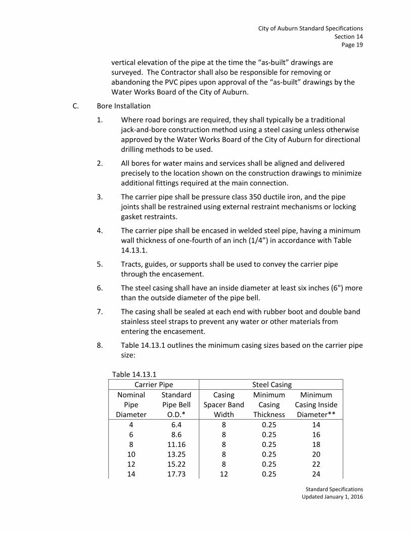
City of Auburn Standard Specifications Section 14
Page 19
Standard Specifications Updated January 1, 2016
vertical elevation of the pipe at the time the “as-built” drawings are surveyed. The Contractor shall also be responsible for removing or abandoning the PVC pipes upon approval of the “as-built” drawings by the Water Works Board of the City of Auburn.
C. Bore Installation
1. Where road borings are required, they shall typically be a traditional jack-and-bore construction method using a steel casing unless otherwise approved by the Water Works Board of the City of Auburn for directional drilling methods to be used.
2. All bores for water mains and services shall be aligned and delivered precisely to the location shown on the construction drawings to minimize additional fittings required at the main connection.
3. The carrier pipe shall be pressure class 350 ductile iron, and the pipe joints shall be restrained using external restraint mechanisms or locking gasket restraints.
4. The carrier pipe shall be encased in welded steel pipe, having a minimum wall thickness of one-fourth of an inch (1/4”) in accordance with Table 14.13.1.
5. Tracts, guides, or supports shall be used to convey the carrier pipe through the encasement.
6. The steel casing shall have an inside diameter at least six inches (6") more than the outside diameter of the pipe bell.
7. The casing shall be sealed at each end with rubber boot and double band stainless steel straps to prevent any water or other materials from entering the encasement.
8. Table 14.13.1 outlines the minimum casing sizes based on the carrier pipe size:
Table 14.13.1 Carrier Pipe Steel Casing
Nominal Pipe
Diameter
Standard Pipe Bell
O.D.*
Casing Spacer Band
Width
Minimum Casing
Thickness
Minimum Casing Inside Diameter**
4 6.4 8 0.25 14 6 8.6 8 0.25 16 8 11.16 8 0.25 18
10 13.25 8 0.25 20 12 15.22 8 0.25 22 14 17.73 12 0.25 24
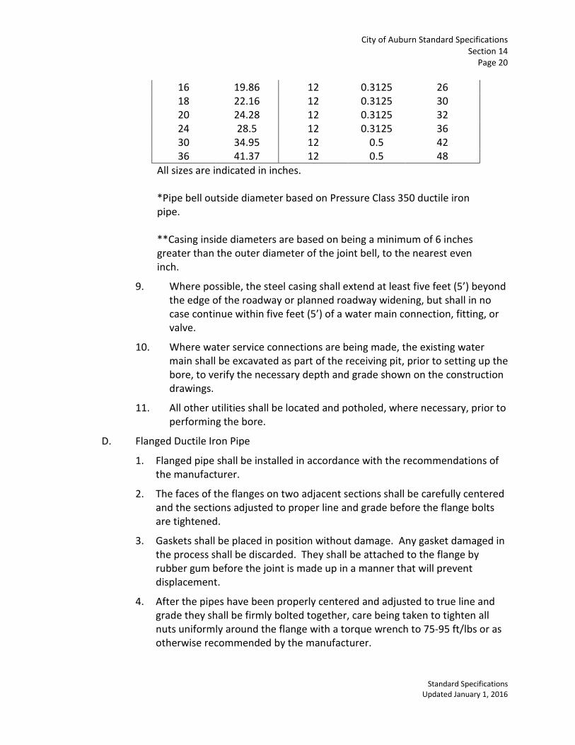
City of Auburn Standard Specifications Section 14
Page 20
Standard Specifications Updated January 1, 2016
16 19.86 12 0.3125 26 18 22.16 12 0.3125 30 20 24.28 12 0.3125 32 24 28.5 12 0.3125 36 30 34.95 12 0.5 42 36 41.37 12 0.5 48
All sizes are indicated in inches. *Pipe bell outside diameter based on Pressure Class 350 ductile iron pipe. **Casing inside diameters are based on being a minimum of 6 inches greater than the outer diameter of the joint bell, to the nearest even inch.
9. Where possible, the steel casing shall extend at least five feet (5’) beyond the edge of the roadway or planned roadway widening, but shall in no case continue within five feet (5’) of a water main connection, fitting, or valve.
10. Where water service connections are being made, the existing water main shall be excavated as part of the receiving pit, prior to setting up the bore, to verify the necessary depth and grade shown on the construction drawings.
11. All other utilities shall be located and potholed, where necessary, prior to performing the bore.
D. Flanged Ductile Iron Pipe
1. Flanged pipe shall be installed in accordance with the recommendations of the manufacturer.
2. The faces of the flanges on two adjacent sections shall be carefully centered and the sections adjusted to proper line and grade before the flange bolts are tightened.
3. Gaskets shall be placed in position without damage. Any gasket damaged in the process shall be discarded. They shall be attached to the flange by rubber gum before the joint is made up in a manner that will prevent displacement.
4. After the pipes have been properly centered and adjusted to true line and grade they shall be firmly bolted together, care being taken to tighten all nuts uniformly around the flange with a torque wrench to 75-95 ft/lbs or as otherwise recommended by the manufacturer.
City of Auburn Standard Specifications Section 14
Page 21
Standard Specifications Updated January 1, 2016
5. Suitable flanged wall fittings or thimbles shall be used where pipes pass through walls of structures.
E. Setting Valves, Valve Boxes, Fittings, and Blow-offs
1. Gate and butterfly valves and pipe fittings shall be set and connected to the pipe in the manner heretofore specified for cleaning, laying and jointing pipe.
2. Cast-Iron valve boxes shall be installed on all underground valves and shall be firmly supported, centered, and plumbed over the operating nut, with box cover flush with finished pavement or slightly above ground surface (approximately ½”) in non-paved areas, unless otherwise directed.
3. Valve boxes shall be installed on a firm base at the proper elevation and then carefully backfilled and tamped.
4. After final backfill has been installed and approved by the Project Engineer, a concrete collar as shown on the standard details shall be installed around each valve box. The annular space between precast collars and valve box shall be grouted in.
5. Valve boxes set in paved areas shall be erected with the top flush with the surface of the pavement in an approved traffic rated enclosure. In its final position the box shall not touch the valve stem at any point.
6. Ductile iron or cast iron pipe shall not be used as a valve box extension unless approved. PVC should never be used as a valve box extension.
7. Drainage branches or blow-offs shall not be connected to any sewer or submerged in any stream or be installed in any other manner that will permit back-siphonage into the distribution system.
F. Setting Fire Hydrants
1. All fire hydrants shall be set plumb and shall conform to the established grade.
2. The center of nozzles shall be between sixteen inches (16”) and twenty inches (20”) above ground surface.
3. Wherever hydrants are set in impervious soil, a drainage pit two feet (2') in diameter and two feet (2') deep shall be excavated below each hydrant and filled compactly with coarse gravel or crushed stone under and around the bowl of the hydrant and to a level six inches (6") above the waste opening. Hydrant drainage pits shall not be connected to a sewer.
4. The bowl of each hydrant shall be well braced against unexcavated earth at the end of the trench with concrete backing, or it shall be tied to the pipe by other means shown on the construction drawings or authorized by the Project Engineer.
City of Auburn Standard Specifications Section 14
Page 22
Standard Specifications Updated January 1, 2016
G. Thrust Restraint
Thrust restraint will be required for all water lines four inches (4”) or larger where unbalanced forces exist. This shall include all ends of main locations where plugs or caps are installed and all changes in size or direction where fittings such as reducers, tees, horizontal bends, vertical bends, etc. are installed. Generally, areas needing thrust restraint shall be minimized by utilizing pipe deflection in lieu of additional bends and fittings. Where required, thrust restraint shall adhere to the practices outlined in the DIPRA Manual for Thrust Restraint design for ductile iron pipe and the City of Auburn standard details. Non-standard thrust blocking will require special detailing provided by a licensed engineer and approved by the Water Works Board of the City of Auburn.
1. Restrained Joint Devices
a) The preferred method of thrust restraint is through the use of externally restrained joint devices such as “Mega-Lug” or approved equal in lieu of concrete blocking.
b) All thrust restraint shall be adequately calculated by the Project Engineer and installed as shown on the construction drawings.
c) The exact linear footage of restraint shall be measured from the flange of the fitting which is being restrained.
2. Concrete Blocking
a) Where approved, reaction or thrust backing of Class “B” Concrete may be applied on pressure pipe lines up to twelve inches (12”) in diameter in lieu of restrained joint devices.
b) All tees, plugs, caps and bends shall be wrapped in plastic prior to pouring concrete.
c) Plastic shall be four (4) mil minimum high-density polyethylene or eight (8) mil minimum low density polyethylene, per AWWA C105.
d) The thrust bearing sides of all concrete blocking shall be poured against firm undisturbed soil and the non-thrust bearing sides shall be formed at an angle to the undisturbed soil.
e) Restraint using metal harnesses, tie rods, pipe clamps, etc. anchored by concrete blocking shall only be used where approved and shown on the construction drawings. Steel rods and clamps shall be of an approved design, galvanized or otherwise rustproof treated, or shall be painted as directed by the Project Engineer.
H. Connection to Existing Mains
1. Except when shown otherwise on the construction drawings, connections to existing water mains shall be made by cutting and removing a portion of the

City of Auburn Standard Specifications Section 14
Page 23
Standard Specifications Updated January 1, 2016
existing pipe and inserting a standard mechanical joint tee (or cross) and a sleeve.
2. At locations shown on the construction drawings, connections to existing mains shall be made by installing tapping sleeves and valves.
3. Connections must be two inches (2”) smaller than existing main when utilizing a stainless steel tapping sleeve.
4. Ductile iron tapping sleeves may be approved on a case by case basis for same size taps.
5. All connections to live mains must be done with a City of Auburn or Water Works Board Inspector present.
6. No taps smaller than one inch (1”) shall be permitted.
14.14 TESTING
A. Hydrostatic Pressure Test
1. All newly installed pressure pipe, or any valved section thereof, shall be subjected to a hydrostatic test at a pressure one and one-half (1-1/2) times the working pressure at the point of testing, but not less than one hundred and fifty pounds per square inch (150 psi).
2. The pipe shall hold the test pressure for a minimum of two hours (2 hrs) with a leakage of no more than five pounds per square inch (5 psi) and shall be recorded on a Bristol Babcock pressure gauge chart.
3. The test shall be conducted at the point directed by the Inspector, Project Engineer, or Owner. The Contractor at his own expense shall install the test point.
4. Each valved section of pipe shall be slowly filled with clean water and the specified pressure shall be applied by means of a pump connected to the pipe in a satisfactory manner. The pump, pipe connection, gauges, meters and other apparatus required for the tests shall be furnished and installed by the Contractor.
5. Before applying the specified test pressure, all air shall be expelled from the pipe. To accomplish this, taps shall be made, if necessary, at points of highest elevation, and afterward tightly plugged or converted to permanent manual air release valves.
6. All exposed pipes, fittings, valves, and joints shall be carefully examined. All leakage in joints shall be completely stopped.
7. Any cracked or defective pipes, fittings, or valves discovered in consequence of this pressure test, shall be removed and replaced by the Contractor with
City of Auburn Standard Specifications Section 14
Page 24
Standard Specifications Updated January 1, 2016
sound material in the manner herein before provided and the test shall be repeated until satisfactory to the Project Engineer.
8. Should any test of combined section of pipe disclose leakage, the Contractor shall, at his own expense, locate and repair the defective joints until the leakage has been completely stopped.
B. Disinfection
1. Completed potable water mains shall be disinfected with chlorine after the mains have been flushed but prior to being placed in service.
2. Each valved section of pipe shall be thoroughly flushed at a rate of at least five feet per second (5 fps), independently, and all dirt and foreign matter shall be removed. Flushing shall be done after pressure testing and either before or after the trench has been backfilled.
3. The Contractor shall pump a solution of calcium hypochlorite (HTH) into the pipe, with the Inspector present, in a manner that will result in a concentration of chlorine of at least fifty parts per million (50 ppm) throughout the pipe.
4. The solution shall remain in the pipe for at least twenty four (24) hours to kill all non-spore forming bacteria, and after twenty four (24) hours the concentration shall be at least twenty five parts per million (25 ppm) in all parts of the pipe
5. All valves shall be operated and services flushed while the pipe contains the chlorine solution, before the twenty four (24) hour contact time clock is started.
6. After disinfection is complete, the chlorinated water shall be flushed from the pipe at its extremities until the replacement water shall, by test, be proven to be safe for human use.
7. The Inspector shall submit water samples, for bacteriological examination to the State Health Department Laboratory, from water mains after chlorination.
8. Should the initial treatment prove ineffective, the procedure shall be repeated until confirmed tests show that water sampled from the pipe conforms to the above requirements.
14.15 MAINTENANCE
The Contractor shall maintain all street and road surfaces, trench backfill and all completed sections of pipelines in good condition until final acceptance of all work by the Water Works Board of the City of Auburn.

City of Auburn Standard Specifications Section 14
Page 25
Standard Specifications Updated January 1, 2016
The Water Works Board of the City of Auburn may use completed sections of the water mains when needed. However, such use shall not relieve the Contractor of his responsibility for maintaining or replacing defective work.

This page intentionally left blank.
STANDARD SPECIFICATIONS
SECTION 15 GRASSING
15.01 GENERAL Specifications in this section shall apply to the establishment of grass, including, but not limited to, plowing, discing, harrowing, grading, placing of topsoil, furnishing grass seed mix or sod, fertilizing, and mulching as necessary. All work under this section shall conform to the ALDOT Standard Specifications for Highway Construction. These specifications are intended to supplement the Alabama Department of Transportation Standard Specifications for Highway Construction. 15.02 TESTING RESPONSIBILITY The cost of testing will be borne by the Contractor, unless otherwise noted in the contract documents. Testing for grassing components will be as outlined in Section 9 or within this section. 15.03 CONTRACTOR RESPONSIBILITY The Contractor is responsible for ensuring an adequate stand of grass and all maintenance until such time as the work is accepted by the City of Auburn. All planting, watering, fertilizing, and mowing shall be conducted at no additional cost to the City as part of the establishment of an adequate stand of grass. 15.04 CONSTRUCTION METHODS
A. Preparation
After all other construction work is completed and the surface finished to subgrade, topsoil shall be spread over the area to be grassed in a uniform layer not less than four inches (4”) thick. Topsoil from other sources, shall be furnished by the Contractor if necessary to cover the area to be planted to the specified depth. Plow and disc in both directions, when feasible, and then remove all large particles that cannot be broken. Carefully finish the entire area to exact line and grade and shape the surface properly around structures. B. Fertilizer and Lime
After ground preparation is complete, the area to be seeded shall then have commercial fertilizer (800 lbs./acre: 13-13-13) and lime (1.5 ton/acre: dolomitic or calcitic lime) applied at the applicable rate.

City of Auburn Standard Specifications Section 15
Page 2
Standard Specifications Updated: January 1, 2016
C. Seeding
1. All seed shall meet the requirements of these specifications and comply with applicable state law. The type of grass seed to be planted shall meet the approval of the Owner. Seed shall be delivered in sealed bags, properly labeled. Seeds of legumes shall be inoculated just before use with the appropriate culture. 2. Sowing of seed shall promptly follow incorporated of fertilizer. Sowing shall be done uniformly by approved mechanical seeders.
3. Immediately after sowing, the seeded area shall be harrowed, dragged, raked, or otherwise worked so as to cover the seed with a layer of soil one and one fourth inches (1¼") thick. After seed is properly covered, the seeded area shall be compacted immediately by means of a cultipacker, light roller, or approved drag.
4. The Contractor shall water, fill washes, and otherwise protect and maintain the seeded areas until the contract is accepted. It shall be the responsibility of the Contractor to establish and maintain a satisfactory stand of grass, a satisfactory stand being defined as a complete cover of living grass (limited to species expected to germinate in the current season).
D. Mulching
Mulching shall consist of covering the sloping areas that have been grassed with straw. Straw shall be threshed oats, wheat, or rye, and shall be applied at the rate of two (2) tons per acre. Mulch materials shall be free of seeds detrimental to the project. If straw is unavailable, hay may be used for mulching. Hay shall be applied at the rate of two (2) tons per acre and may be Sudan grass, broom sedge, or grass clippings. Mulch shall be applied immediately and uniformly after seeding is complete. Mulch materials shall be free of seeds detrimental to the project. E. Sodding
1. When sod is to be placed, it shall match the existing sod, unless otherwise noted in the construction documents.
Standard Specifications Section 15
Page 3
Standard Specifications Updated: January 1, 2016
2. Immediately after placement, the sodded area shall be compacted immediately by means of a cultipacker, light roller, or other approved method. 3. The Contractor shall water, fill washes, and otherwise protect and maintain the sodded areas until the contract is accepted. It shall be the responsibility of the Contractor to establish and maintain a satisfactory stand of grass, a satisfactory stand being defined as a complete cover of living grass.
15.05 GRASS BOND A grassing bond will be required to cover all grassed area, solid sod areas, and erosion control for one year after the time of planting seed or placing sod.

This page intentionally left blank.
STANDARD SPECIFICATIONS
SECTION 16 STORM SEWER SYSTEMS
16.01 GENERAL Specifications in this section shall apply to the construction of storm sewer systems including excavation, trenching, backfilling, materials, and testing for culverts, inlets, headwalls, junction boxes, area inlets, riprap, ditches, and other structures. These specifications are intended to supplement the Alabama Department of Transportation Standard Specifications for Highway Construction. They shall take precedence over the Alabama Department of Transportation Standard Specifications except on State highways. For items not covered by these specifications, the Alabama Department of Transportation standard specifications shall apply. All pipes must have an ALDOT stamp on the inside of the pipe. 16.02 TESTING RESPONSIBILITY The cost of testing will be borne by the Contractor, unless otherwise noted in the contract documents. Testing for storm sewer components will be as outlined in Section 9 or within this section. 16.03 CONTRACTOR RESPONSIBILITY The contractor is responsible for subsurface investigation, construction, testing, etc. and perform all work required to complete the project. The plans show certain features of topography and certain underground utilities, but they do not purport to show in complete detail all such lines or underground features. Such topography and notes on the plans are inserted from records available and are for the Contractor's convenience only and shall not be used as a basis for claims of extra compensation. Wherever necessary to determine the location of existing pipes, valves, or other underground structures, the Contractor shall examine all available records and shall make all explorations and excavations for such purpose. The Contractor at no cost to the Owner shall immediately repair any damage to existing facilities resulting from the Contractor’s operations. In previously grassed areas, the Contractor is responsible for sodding with the same type grass. In unimproved areas, the disturbed ground shall be seeded with an approved Alabama Department of Transportation mix. During the course of the work outlined in this section, the contractor shall do all bracing, sheathing, and shoring necessary to perform and protect all excavations, installations, and drop offs as required for safety or to conform to governing laws. The contractor is solely responsible for all safety of the work. Traffic control devices shall be installed in accordance with the Manual on Uniform Traffic Control Devices, latest edition, and meet regulations outlined in the ALDOT Standard Specifications for Highway Construction, latest edition.

City of Auburn Standard Specifications
Section 16 Page 2
Standard Specifications Updated: January 1, 2016
The contractor is responsible for submission of all shop drawings and submittals for all materials to be used on the project prior to using the materials. The contractor shall submit three (3) copies for review and approval by the Inspection Manager for the City of Auburn. 16.04 EXCAVATION AND BACKFILLING
A. Excavation The Contractor shall do all excavation of whatever substances encountered to the depth required to install the structure. Excavated materials not required for fill or backfill shall be removed from the site and disposed of by the Contractor at a location he deems appropriate. Excavation for inlets, headwalls, junction boxes, and other structures shall have twelve inch (12") minimum clearance on all sides. The ground adjacent to all excavations shall be graded to prevent water from running in. Unsuitable soil shall be removed and replaced with gravel, crushed stone, or crushed slag, which shall be thoroughly tamped. Excess excavation below required level shall be backfilled with earth, sand, gravel, crushed stone, or concrete, approved by the Engineer or Project Manager, and thoroughly tamped. The Contractor shall remove any water accumulated in the excavation and keep the trench dewatered until the bedding is complete. In rock, excavations shall be carried six inches (6") below the bottom of the pipe. Loose earth or gravel not larger than three fourths of an inch (3/4") in size shall be used for backfill, tamped thoroughly, and rounded to receive pipe as above. All work with explosives shall be done in such a manner as not to endanger life or property. All storage places for explosives and inflammable materials shall be clearly marked. The method of storing and handling such materials shall conform to all Federal, State, and local laws.
City of Auburn Standard Specifications
Section 16 Page 3
Standard Specifications Updated: January 1, 2016
B. Backfilling After pipes have been visually checked for defects, backfilling shall be done with approved material free from large clods or stones, sticks, logs, stumps, construction debris, or other unsuitable materials. Backfill material shall be placed evenly and carefully around and over pipe in six-inch (6") maximum layers. Each layer shall be thoroughly and carefully tamped until one foot (1') of cover exists over pipe. The remainder of backfill materials shall be placed in twelve inch (12") to eighteen-inch (18") layers and compacted. For trenches under roadways and areas to be paved, material shall be placed in eight-inch (8") maximum layers after filling one foot (1') above pipe as previously described. Each layer shall be compacted to 95% for the underlying layers and 98% for the top 6”so that pavement can be placed immediately. The Contractor shall refill for settlement all backfilled areas.
At inlets, junction boxes, headwalls, and other structures, all forms, trash, and debris shall be removed and cleared away. Weep holes one and one half inch (1 ½") in diameter shall be installed in the walls of all inlets and junction boxes. The pipe end shall be covered with filter fabric, as shown on the City of Auburn standard details.
For pipes and culverts in fill section or projecting into fill section, where pipe is not structurally supported, unstable material shall be removed. A pipe bed and embankment, if required, shall be constructed of selected material and compacted. Selected material shall be placed symmetrically on each side of pipe to a point one foot (1') above the pipe in six inch (6") maximum layers and compacted. C. Replacing Pavement The minimum width of replaced concrete pavements shall be four feet (4') at interiors and six feet (6') at joints. Avoid cutting pavements at joints; if unavoidable, reconstruct same as or better than original joint. Depth shall be one and one third (1 1/3) times original thickness. Existing pavement edges shall be cut vertically. Use 1: 2: 3 mix, water-cement ratio five (5) gallons; use high-early-strength cement if road is to be opened in less than three (3) days.

City of Auburn Standard Specifications
Section 16 Page 4
Standard Specifications Updated: January 1, 2016
The minimum width of replaced bituminous pavements shall be three feet (3') with base of same depth as original pavements. (Replacement should conform to the street classification and utility patch detail.) The existing pavement shall be saw cut vertically and horizontally to a straight line. Edge of existing pavement shall be painted with SS-1 or SS1h tack. The patch shall be rolled in both directions with at least a five-ton roller. When a pavement cut will be left unpaved for more than twenty four hours (24 hrs.), the cut shall be covered with steel plates of such strength to allow traffic to proceed unobstructed, or should be backfilled with crusher run stone and maintained for traffic. If the cut will be left unpaved overnight, adequate warning devices shall be used to notify motorists of the obstruction.
16.05 CULVERTS
A. General All culverts shall be installed according to the sizes, materials, slopes, locations, and elevations as shown on the plans approved by the City Engineer. Any changes in the approved plans shall receive written approval by the City Engineer before they are implemented. Any changes made without such approval shall be done at the Contractor's risk. All reinforced concrete pipe must be stamped ALDOT approved and be bedded with the appropriate bedding material. B. Material Properties All pipes within the right of way and easements shall be reinforced concrete pipe, unless otherwise approved by the City Engineer. Pipe shall conform to the specifications outlined in the ALDOT Standard Specifications for Highway Construction, latest edition, Sections 500 and 800. Culverts shall be in accordance with the following:
• Concrete Sewer Pipe and Fittings, A.S.T.M. C-14; • Reinforced Concrete Sewer Pipe and Fittings, A.S.T.M. C-76; • Concrete Pipe may be bell and spigot except that tongue and groove shall be used
for sizes over twenty one inches (21"); • Bituminous Coated Corrugated Metal Pipe shall meet the requirements of
A.A.S.H.T.O. M-36 for Type I and II Culverts. Construction requirements shall be

City of Auburn Standard Specifications
Section 16 Page 5
Standard Specifications Updated: January 1, 2016
done in accordance with Section 840, Alabama Highway Department Standards for Highway Construction.
• Precast box culvert A.S.T.M. C-850; A.A.S.H.T.O. 259 C. Construction Methods
All pipe shall be laid with ends abutting and with not more than one-inch (1”) variation from established alignment at the vertical centerline or from grade at the flowline. All joints and lift holes shall be wrapped with filter material or grouted over to eliminate infiltration. The width of the trench shall be six-inch (6") minimum, eight inch (8") maximum on each side of the pipe bell. The bottom of the trench for sewers and culverts shall be rounded so that an arc of the circumference is equal to six tenths (0.6) of the outside diameter of the pipe rests on undisturbed soil. Bell holes shall be excavated accurately to size by hand.
16.06 INLETS AND JUNCTION BOXES
A. Material Properties Inlets and junction boxes can be poured in place or precast. Poured in place structures must use a minimum 3000 psi concrete mix and reinforcing steel as outlined on the standard details. For culverts thirty-six inches (36") in diameter and smaller, precast reinforced concrete manholes may be used in lieu of poured-in-place concrete. Larger sizes must be approved prior to use. B. Construction Methods For poured-in-place structures, forms shall be clean and free from dirt. Reinforcing steel shall be free from dirt, rust, oils, or other defects. The reinforcing steel shall be placed no closer than two inches (2") to any outside concrete surface. Edges of exposed concrete shall be chamfered. Frames, covers and gratings shall be flush with the finished surface of the concrete.
Inlet Top replacement involves forming and pouring a minimum of an eight-inch (8") thick

City of Auburn Standard Specifications
Section 16 Page 6
Standard Specifications Updated: January 1, 2016
concrete reinforced concrete pad with ring and cover over existing structures. The reinforcement shall be number five (#5) bars on four-inch (4") centers both directions.
16.07 HEADWALLS
A. Material Properties Headwalls can be poured in place or precast. Poured in place structures must use a minimum 3000-psi concrete mix and reinforcing steel as outlined on the standard details. Precast headwalls must be approved prior to use. If precast headwalls are used, the back slope from the curb and gutter and/or sidewalk must be at least 3:1. Steeper slopes will not be allowed. B. Construction Methods Headwalls shall have a rubbed smooth finish and the pipe shall be cut flush with the inside face of the headwall. Chamfer strips are required on all headwalls.
16.08 DITCHES
A. Material Properties Ditches can have several forms – sodden, concrete, natural, or riprap. The material chosen must be in accordance with the engineer’s design, based on erosive velocity. (See City of Auburn Storm Water Management Manual for other information). Riprap shall consist of a protective course of stone in channels and ditches, with geotextile filter, in accordance with the Alabama Department of Transportation Standard Specifications for Highway Construction, latest edition. The riprap size to be used shall be determined by the engineer of record. B. Construction Methods Ditches shall be Trapezoidal, as shown on the City of Auburn standard details. Vee-bottom ditches will not be allowed. Where earthen ditches are to be constructed, the bottom and sides shall be shaped as
City of Auburn Standard Specifications
Section 16 Page 7
Standard Specifications Updated: January 1, 2016
shown on the Plans as approved by the City Engineer. Ditches shall be constructed to provide a smooth flowing, unobstructed waterway. During the construction of the proper cross section, grade and alignment, the bottom and sides of the ditch shall be compacted to eliminate excessive erosion. Any areas disturbed during construction shall be seeded and mulched. Where hand-placed riprap ditches are to be constructed, the surface to be covered shall be fully compacted and graded to the required slope. Riprap on slopes shall commence in a trench below the toe of the slope and shall progress upward, each stone being laid by hand perpendicular to the slope with the long dimension vertical, firmly bedded against the slope and against the adjoining stone, with ends in contact, and with well-broken joints. The finished surface of the riprap shall present an even, tight surface, not less than twelve inches (12") thick, measured perpendicular to the slope. The stones shall be so laid that the weight of the large stones is carried by the soil rather than by adjacent stones. Where dumped riprap ditches are to be constructed, the riprap shall be placed directly in the locations and to the contours shown on the Plans by dumping in final position as nearly as practicable. Prior to dumping, the ditch must be shaped and/or notched to receive the riprap and allow for proper embedment.
Where concrete-lined ditches or flumes are to be constructed, the cross-section, grade, and alignment shall be as shown on the Plans as approved by the City Engineer. Placement, finishing, curing, and testing shall comply to the same requirements as for Portland Cement Concrete Pavements.
16.09 PLUGGING/REMOVAL OF EXISTING PIPE AND STRUCTURES The plugging/removal of existing pipe and structures shall be done in accordance with the Contract drawings and as directed by the Engineer. Payment will be as outlined in the contract documents.