Embed Size (px)
Citation preview

City of Denton
Drainage Design Criteria Manual
July 26, 2013

Drainage Design Criteria Manual
i
Table of Contents
Section 1.0 – Introduction ........................................................................ 1
1.1 Purpose ......................................................................................................................................... 1
1.2 Design Criteria............................................................................................................................... 1
1.3 Definitions ...................................................................................................................................... 1
Section 2.0 – Definitions .......................................................................... 2
Section 3.0 Design Criteria .................................................................... 10
3.1 Hydrologic Methods .................................................................................................................... 10
3.1.1 Types of Hydrologic Methods .............................................................................................. 10
3.1.2 Rainfall Estimation............................................................................................................... 12
3.2 Acceptable Downstream Conditions for Open Channels and Floodplains ................................. 13
3.3 Flood Mitigation ................................................................................................................................. 14
3.3.1 Introduction .......................................................................................................................... 14
3.3.2 Flood Mitigation Design Options ......................................................................................... 14
3.4 Stormwater System Design .............................................................................................................. 15
3.4.1 Introduction .......................................................................................................................... 15
3.4.2 Hydraulic Design Criteria for Streets and Closed Conduits ................................................ 15
3.4.3 Hydraulic Design Criteria for Structures .............................................................................. 32
3.4.4 Channel Drop Strutures .............................................................................................................. 37
3.4.5 Maintenance Access ................................................................................................................... 37
3.5 Culverts………………………………………………………………………………………………………38
3.6 Bridges………………………………………………………………………………………………………..39
3.7 Detention Structures…………………………………………………………………………………………39
3.7.1 Outlet Structures for Detention and Retention Structures………………………………………..40
3.8 Energy Dissipation………………………………………………………………………………………….43

Drainage Design Criteria Manual
1
Section 1.0 – Introduction
1.1 Purpose
These design criteria and the NCTCOG iSWMTM
Hydrology and Hydraulics Technical Manuals together shall be known as the Drainage Design Criteria Manual. The purpose of this drainage criteria and the iSWM
TM Hydraulics and Hydrology Technical Manuals is to establish standard principles and practices for
the design and construction of storm drainage systems within the City of Denton, Texas and within its extraterritorial jurisdiction. The design factors, formulae, graphs and procedures are intended for use as minimum engineering criteria for the design of drainage systems involving determination of the quantity, rate of flow, method of collection, storage, conveyance, detention and disposal of storm water. Responsibility for actual design remains with the design engineer. Users of this manual should be knowledgeable and experienced in the theory and application of drainage engineering.
1.2 Design Criteria
A. These drainage design criteria are not intended to be a complete set of design criteria and the Denton Development Code shall be consulted for additional criteria.
B. The drainage design criteria contained in this manual do not supersede the criteria contained in the Denton Development Code and any revisions to the Denton Development Code shall supersede the criteria in this manual.
C. The NCTCOG iSWMTM
Hydraulics and Hydrology Technical Manuals are acceptable methodologies that can be used to meet the City’s minimum design criteria.
D. The drainage criteria contained under Section 3.0 of this manual supersedes any design criteria contained in the iSWM
TM Hydraulics and Hydrology Technical Manuals.
E. Any deviation from the criteria and principles of this manual must be approved by the City Engineer.
1.3 Definitions
A complete "Glossary" of terms and abbreviations used in the text of this manual is presented in the Section 2.0.

Drainage Design Criteria Manual
2
Section 2.0 – Definitions Abutment -A wall supporting the end of a bridge or span, and sustaining the pressure of the abutting
earth.
Apron- A floor or lining of concrete, timber, or other suitable material at the toe of a dam, entrance or discharge side of a spillway, a chute, or other discharge structure, to protect the waterway from erosion from falling water or turbulent flow.
Backwater- The rise of the water level upstream due to an obstruction or constriction in the channel.
Backwater Curve -The term applied to the longitudinal profile of the water surface in an open channel when flow is steady but non-uniform.
Baffle Chute -A drop structure in a channel with baffles for energy dissipation to permit the lowering of the hydraulic energy gradient in a short distance to accommodate topography.
Baffles - Deflector vanes, guides, grids, gratings, or similar devices constructed or placed in flowing water, to: (1) check or effect a more uniform distribution of velocities; (2) absorb energy; (3) divert, guide, or agitate the liquids; and (4) check eddy currents.
Calibration- Process of checking, adjusting, or standardizing operating characteristics of instruments and model appurtenances on a physical model or coefficients in a mathematical model. The process of evaluating the scale readings of an instrument in terms of the physical quantity to be measured.
Channel Roughness -Irregularities in channel configuration which retard the flow of water and dissipate its energy.
Chute- An inclined conduit or structure used for conveying water to a lower level.
Conduit - Any open or closed device for conveying flowing water.
Continuity -Continuity of flow exists between two sections of a pipe or channel when the same quantity of water passes the two cross sections and all intermediate cross sections at anyone instant.
Critical Flow -The state of flow for a given discharge at which the specific energy is a minimum with respect to the bottom of the conduit. The Froude Number is equal to 1.0 for critical flow conditions.
Crown- (I) The highest point on a transverse section of conduit, (2) the highest point of a roadway cross
section. Culvert- Large pipe or other conduit through which a small stream passes under a road or street.
Curb - A vertical or sloping structure located along the edge of a roadway, normally constructed
integrally with the gutter, which strengthens and protects the pavement edge and clearly defines the pavement edge to vehicle operators.
Dam - A barrier constructed across a watercourse for the purpose of (I) creating a reservoir, (2) diverting water there from a conduit or channel.

Drainage Design Criteria Manual
3
Degradation -The progressive general lowering of a stream channel by erosion, other than that caused by a constriction.
Depression Storage -Collection and storage of rainfall in natural depressions (small puddles) after exceeding infiltration capacity of the soil.
Design Storm or Flood -The storm or flood which is used as the basis for design, i.e., against which the structure is designed to provide a stated degree of protection or other specified result.
Detention -The storage of storm runoff for a controlled release during or immediately following the design storm.
a) Off-site detention -A detention pond located outside the boundary of the area it serves.
b) On-site detention -A detention pond which is located within and serves only a specific site or subdivision.
c) Regional detention -Detention facilities provided to control excess runoff based on a watershed-wide hydrologic analysis.
Drop Structures -A sloping or vertical section of a channel designed to reduce the elevation of flowing water without increasing its velocity.
Entrance Head -The head required to cause flow into a conduit or other structure; it includes both entrance loss and velocity head.
Entrance Loss -Head lost in eddies or friction at the inlet to a conduit, headwall or structure. Flash Flood -A flood of short duration with a relatively high peak rate of flow, usually resulting from a high
intensity rainfall over a small area.
Flood Control -The elimination or reduction of flood losses by the construction of flood storage reservoirs, channel improvements, dikes and levees, by-pass channels, or other engineering works.
Flood Fringe -Part of the flood hazard area outside of the floodway. Flood Hazard Area -Area subject to flooding by l00-year frequency floods
Flood Management or Flood Hazard Mitigation -Any program or activity designed to reduce damages
from flooding, including stream erosion.
Flood Plain -Geographically the entire area subject to flooding. In usual practice, it is the area subject to flooding by the l00-year frequency flood.
Floodway- The channel of a stream and adjacent areas reserved to facilitate passage of a l00-year frequency flood.
Freeboard -The distance between the normal operating level and the top of the side of an open conduit left to allow for wave action, floating debris, or any other condition or emergency without overtopping the structure.
Frequency (of storms, floods) -Average recurrence interval of events, over long periods of time. Mathematically, frequency is the reciprocal of the exceedance probability.
Drainage Design Criteria Manual
4
Froude Number -A flow parameter, which is a measure of the extent to which gravitational action affects the flow. A Froude number greater than 1 indicates supercritical flow and a value less than 1 subcritical flow. The simplest form of the Froude number is given by the equation:
F = V/(gD)
0.5
where: V = Velocity g = the acceleration due to gravity (32.2 ft/sec/sec) D = depth
Gabion - A wire basket containing earth or stones, deposited with others to provide protection against
erosion.
Grade- (1) The inclination or slope of a channel, canal, conduit, etc., or natural ground surface, usually expressed in terms of the percentage of number of units of vertical rise (or fall) per unit of horizontal distance. (2) The elevation of the invert of the bottom of a conduit, canal, culvert, sewer, etc. (3) The finished surface of a canal bed, road bed, top of an embankment, or bottom of excavation.
Gutter - A generally shallow waterway adjacent to a curb used or suitable for drainage of water.
Headwater- (1) The upper reaches of a stream near its sources; (2) the region where ground waters
emerge to form a surface stream; (3) the water upstream from a structure.
High Intensity Node -Areas of existing or proposed development that contain a large concentration of buildings and large amounts of pavement. High Intensity nodes typically generate large volumes of traffic and increased volumes of storm water runoff.
Hydraulic Control -The hydraulic characteristic which determines the stage-discharge relationship in a
conduit. The control is usually critical depth, tailwater depth, or uniform depth.
Hydraulic Grade Line -A line representing the pressure head available at any given point within the system.
Hydraulic Gradient -A hydraulic profile of the piezometric level of the water, representing the sum of the depth of flow and the pressure head. In open channel flow it is the water surface.
Hydraulic Jump -The hydraulic jump is an abrupt rise in the water surface which occurs in an open channel when water flowing at supercritical velocity is retarded by water flowing at subcritical velocity. The transition through the jump results in a marked loss of energy, evidenced by turbulence of the flow within the area of the jump. The hydraulic jump is sometimes used as a means of energy dissipation.
Hydraulics -A branch of science that deals with practical applications of the mechanics of water movement.
Hydrograph -A graph showing stage, flow, velocity or other property of water versus time at a given point on a stream or conduit. a) Dimensionless Unit hydrograph
b) Unit Hydrograph
c) 10-minute unit hydrograph
d) Flood Hydrograph

Drainage Design Criteria Manual
5
Hydrology -The science that deals with the processes governing the depletion and replenishment of the
water resources of the land areas of the earth.
Hyetograph -A histogram or graph of rainfall intensity versus time of storm.
Impervious -A term applied to a material through which water cannot pass, or through which water passes with great difficulty.
Infiltration- (I) The entering of water throu9h the interstices or pores of a soil or other porous medium. (2) The quantity of groundwater which leaks into a sanitary or combined sewer or drain through defective joints. (3) The entrance of water from the ground into a sewer or drain through breaks, defective joints, or porous walls. (4) The absorption of water by the soil, either as it falls as precipitation, or from a stream flowing over the surface.
Inlet- (I) An opening into a storm sewer system for the entrance of surface storm runoff, more completely described as a storm sewer inlet, (2) A structure at the diversion end of a conduit, (3) The upstream connection between the surface of a ground and a drain or sewer, for the admission of surface or storm water.
Inlet Types a) Curb Opening Inlet -A vertical opening in a curb through which the gutter flow passes. The
gutter may be undepressed or depressed in the area of the curb opening.
b) Grated Inlet -An opening in the gutter covered by one or more grates through which the water falls. As with all inlets, grated inlets may be either depressed or undepressed and may be located either on a continuous grade of in a sump.
c) Drop Inlet -A storm drain intake structure typically located in unpaved areas. The inlet may extend above the ground level with openings on one or more sides of the inlet or it may be flush with the ground with a grated cover.
Intensity -As applied to rainfall, a rate usually expressed in inches per hour.
Interception -As applied to hydrology, refers to the process by which precipitation is caught and held by foliage, twigs, and branches of trees, shrubs and buildings, never reaching the surface of the ground, and then lost by evaporation.
Invert -The floor. bottom. or lowest portion of the internal cross section of a conduit. Used particularly with
reference to aqueducts, sewers, tunnels, and drains.
Lag Time -The time difference between two occurrences. such as between rainfall and runoff or pumping of a well and effect on the stream. See Time of Concentration.
Lining- Impervious material such as concrete, clay, grass, plastic, puddled earth. etc.. placed on the sides and bottom of a ditch, channel, and reservoir to prevent or reduce seepage of water through the sides and bottom and/or to prevent erosion.
Lip -A small wall on the downstream end of an apron. to break the flow from the apron.
Manning Coefficient -The coefficient of roughness used in the Manning Equation for flow in open channels.

Drainage Design Criteria Manual
6
Manning Equation -A uniform flow equation used to relate velocity, hydraulic radius and the energy gradient slope.
Model -Mathematical systems analysis by computer, applied to evaluate rainfall-runoff relationships; simulate watershed characteristics, predict flood and reservoir routings, or use other aspects of planning.
Nappe -The sheet or curtain of water overflowing a weir or dam. When freely overflowing any given
structure. it has a well-defined upper and lower surface.
100-year Event -Event (rainfall or flood) that has a 1% chance of being equalled or exceeded in any given year.
Open Channel -A conduit in which water flows with a free surface.
Orifice- (1) An opening with closed perimeter, and of regular form in a plate, wall, or partition through which water may flow. (2) The end of a small tube, such as a Pilot tube, piezometer, etc.
Peak Flow (Peak Rate of Runoff) -The maximum rate of runoff during a given runoff event. Percolation -To pass through a permeable substance such as ground water flowing through an aquifer. Permeability- The property of a material which permits movement of water through it when saturated and
actuated by hydrostatic pressure. Pervious -Applied to a material through which water passes relatively freely. Porosity- (1) An index of the void characteristics of a soil or stratum as pertaining to percolation; degree
of perviousness. (2) The ratio, usually expressed as a percentage, of (a) the volume of the interstices in a given quantity of material, to (b) the total volume of the material.
Post-development -The condition of the given site and drainage area after the anticipated development
has taken place. Precipitation -Any moisture that falls from the atmosphere, including snow, sleet, rain and hail. Pre-development -The condition of the given site and drainage area prior to development. Prismatic Channel -A channel built with unvarying cross section and constant bottom slope. Probable Maximum Flood (PMF) -The flood that may be expected from the most severe combination of
critical meteorological and hydrologic conditions that are reasonably possible in the region. Probable Maximum Precipitation (PMP) -The critical depth-duration-area rainfall relationship for a given
area during the seasons of the year which would result from a storm containing the most critical meteorological conditions considered probable of occurring.
Rainfall Duration -The length of time over which a single rainfall event occurs, averaged over long
periods of time. Rainfall Frequency -The average recurrence interval of rainfall events, averaged over long periods of
time. Rainfall Intensity -The rate of accumulation of rainfall, usually in inches of millimetres per hours.

Drainage Design Criteria Manual
7
Rational Formula -A traditional means of relating runoff from an area and the intensity of the storm rainfall.
Reach -Any length of river or channel. Usually used to refer to sections which are uniform with respect to
discharge, depth, area or slope, or sections between gaging stations. Recurrence Interval -The average interval of time within which a given event will be equaled or
exceeded once. For an annual series (as opposed to a partial duration series) the probability of occurrence in anyone year is the inverse of the recurrence interval. Thus a flood having a recurrence interval of 100 years has a 1 percent probability of being equaled or exceeded in any one year.
Return Period -See Recurrence Interval Reynold’s Number -A flow parameter which is a measure of the viscous effects on the flow. Typically
defined as: Re = VD/
V
where V = Velocity D = Depth v = kinematic viscosity of the fluid Rigid Pipe -Any concrete, clay or cast iron pipe. Riprap (Revetment) -Forms of bank protection, usually using rock. Riprap is a term applied to stone
which is dumped rather than placed more carefully. Routing- Routing is a technique used to predict the temporal and spatial variations of a flood wave as it
traverses a river reach or reservoir. Generally, routing technique may be classified into two categories -hydrologic routing and hydraulic routing.
ROW (Right-of-Way) -A strip of land dedicated for public streets and/or related facilities, including utilities
and other transportation uses. ROW Width -The shortest horizontal distance between the lines which delineate the right-of-way of a
street. Runoff- That part of the precipitation which reaches a stream, drain, sewer, etc., directly or indirectly.
a) Direct Runoff -The total amount of surface runoff and subsurface storm runoff which reaches stream channels.
b) Overland Runoff -Water flowing over the land surface before it reaches a definite stream channel or body of water.
Runoff Coefficient -A decimal number used in the Rational Formula which defines the runoff
characteristics of the drainage area under consideration. It may be applied to an entire drainage basin as a composite representation or it may be applied to a small individual area such as one residential lot.
Runoff Total -The total volume of flow from a drainage area for a definite period of time such as a day,
month, or a year, or it may be for the duration of a particular storm. Scour -The erosive action of running water in streams or channels in excavating and carrying away
material from the bed and banks.

Drainage Design Criteria Manual
8
SCS Runoff Curve Number -Index number used by the National Resource Conservation Service,
Formerly the Soil Conservation Service, as a measure of the tendency of rainfall to run off into streams rather than evaporate or infiltrate.
Sediment -Material of soil and rock origin transported, carried, or deposited by water. Sidewalk- A paved area within the street right-of-way or sidewalk easement specifically designed for
pedestrians and/or bicyclists. Slope, Critical -The slope or grade of a channel that is exactly equal to the loss of head per foot resulting
from flow at a depth that will give uniform flow at critical depth; the minimum slope of a conduit which will produce critical flow.
Slope, Friction -The friction head or loss per unit length of channel or conduit. For uniform flow the
friction slope coincides with the energy gradient, but where a distinction is made between energy losses due to bends, expansions, impacts, etc., a distinction must also be made between the friction scope and the energy gradient. The friction slope is equal to the bed or surface slope only for uniform flow in uniform open channels.
Soffit -The bottom of the top of a pipe. In a sewer pipe, the uppermost point on the inside of the structure.
The crown is the uppermost point on the outside of the pipe wall. Spillway -A waterway in or about a dam or other hydraulic structure, for the escape of excess water. Also
referred to as By-Channel, By-Wash, and Diversion Cut. Steady Flow -Open channel flow is said to be steady if the depth of flow does not change or if it can be
assumed to be constant during the time interval of consideration. Stilling Basin -Pool of water conventionally used, as part of a drop structure or other structure, to
dissipate energy. Storm Hydrology -The branch of hydrology that concentrates on the calculation of runoff from storm
rainfall. Stormwater Management -The control of storm runoff on-site or on small streams, by means of land use
restrictions, detention storage, erosion control, and/or drainage. Stormwater Model -Mathematical method of solving stormwater problems by computer technology. Subcritical Flow -Relatively deep, tranquil flow with low flow velocities. The Froude Number is less than
1.0 for subcritical flow conditions. Supercritical Flow -Relatively shallow, turbulent flow with high flow velocities. The Froude Number is
greater than 1.0 for supercritical flow conditions. Tailwater- The depth of flow in the stream directly downstream of a drainage facility. Time of Concentration -The estimated time in minutes required for runoff to flow from the most remote
section of the drainage area to the point at which the flow is to be determined. Total Head Line (Energy Line) -A line representing the energy in flowing water. The elevation of the
energy line is equal to the elevation of the flow line plus the depth plus the velocity head plus the pressure head.
Trash Rack -Racks, gratings, or mesh designed so as to prevent leaves and rubbish from plugging the
outlets from a dam or detention basin.

Drainage Design Criteria Manual
9
Trunk Line -The main line of a storm drain system extending from manhole to manhole or from manhole
to outlet structure. Uniform Channel -A channel with a constant cross section and roughness. Uniform Flow -Open channel flow is said to be uniform if the depth of flow is the same at every section of
the channel. Unit Hydrograph -The direct runoff hydrograph resulting from one inch of precipitation excess distributed
uniformly over a watershed for a specified duration. Velocity Head -The energy per unit weight of water due to its velocity (v). The velocity head also
represents the vertical distance water must fall freely under gravity to reach its velocity (v). The velocity head can be computed from:
Vel. Head = V
2/2g
V = Velocity g = acceleration due to gravity (g = 32.2 feet per second) Warped Headwall -The wingwalls are tapered from vertical at the abutment to a stable bank slope at the
end of the wall. Water Year -The water year commonly used in the United States is the period from October 1 to
September 30 of the following calendar year. Watershed -The area contributing storm runoff to a stream or drainage system. Other terms are drainage
area, drainage basin and catchment area.

Drainage Design Criteria Manual
10
Section 3.0 Design Criteria Section 3.0 of this manual includes the criteria for addressing the key adverse impacts of development on stormwater runoff.
Design Focus Areas
The design criteria for stormwater management include the following Focus Areas:
Streambank Protection: Regulate discharge from the site to minimize downstream bank and channel erosion
Flood Mitigation and Conveyance: Control runoff within and from the site to minimize flood risk to people and properties for the conveyance storm as well as the 100-year storm.
Design Storms
Design is based on the following four (4) storm events.
Table 3.0 Storm Events
Storm Event Name Storm Event Description
“Water Quality” Criteria based on a volume of 1.5 inches of
rainfall, not a storm frequency
“Streambank Protection” 1-year, 24-hour storm event
`“Conveyance” 25-year, 24-hour storm event
“Flood Mitigation” 100-year, 24-hour storm event
Throughout the manual the storms will be referred to by their storm event names.
For design of closed pipe systems, culverts, open channels, the City of Denton requires use of
the Flood Mitigation storm event (100-yr, 24-hour storm event) only, unless specified otherwise in
the manual.
3.1 Hydrologic Methods
3.1.1 Types of Hydrologic Methods
There are a number of empirical hydrologic methods available to estimate runoff characteristics for a site or drainage sub basin. However, the following methods have been selected to support hydrologic site analysis for the design methods and procedures included in this manual:
Rational Method
SCS Unit Hydrograph Method
Snyder’s Unit Hydrograph Method

Drainage Design Criteria Manual
11
USGS & TXDOT Regression Equations Table 3.1 lists the hydrologic methods and the circumstances for their use in various analysis and design applications. Table 3.2 provides some limitations on the use of several methods. In general:
The Rational Method is acceptable for small, highly impervious drainage areas, such as parking lots and roadways draining into inlets and gutters.
The U.S. Geological Survey (USGS) and Texas Department of Transportation (TXDOT) regression equations are acceptable for drainage areas with characteristics within the ranges given for the equations shown in Table 3.2. These equations should not be used when there are significant storage areas within the drainage basin or where other drainage characteristics indicate general regression equations are not appropriate.
Table 3.1 Applications of the Recommended Hydrologic Methods
Method Rational Method
SCS Method
Modified Rational
Snyder’s Unit
Hydrograph
USGS / TXDOT
Equations
Streambank Protection Volume (SPv)
Flood Mitigation Discharge (Qf)
Storage Facilities
Outlet Structures
Gutter Flow and Inlets
Storm Drain Pipes
Culverts
Bridges
Small Ditches
Open Channels
Energy Dissipation

Drainage Design Criteria Manual
12
Table 3.2 Constraints on Using Recommended Hydrologic Methods
Method Size Limitations1 Comments
Rational 0 – 100 acres
Method can be used for estimating peak flows and
the design of small site or subdivision storm sewer
systems.
Modified Rational2 0 – 200 acres
Method can be used for estimating runoff volumes for storage design.
Unit Hydrograph (SCS)3
Any Size Method can be used for estimating peak flows and hydrographs for all design applications.
Unit Hydrograph
(Snyder’s)4
1 acre and larger
Method can be used for estimating peak flows and
hydrographs for all design applications.
TXDOT Regression
Equations 10 to 100 mi
2
Method can be used for estimating peak flows for
rural design applications.
USGS Regression
Equations 3 – 40 mi
2
Method can be used for estimating peak flows for
urban design applications.
1 Size limitation refers to the drainage basin for the stormwater management facility (e.g., culvert, inlet).
2 Where the Modified Rational Method is used for conceptualizing, the engineer is cautioned that the method could
underestimate the storage volume. 3
This refers to SCS routing methodology included in many readily available programs (such as HEC-HMS or HEC-
1) that utilize this methodology.
4 This refers to the Snyder’s methodology included in many readily available programs (such as HEC-HMS or
HEC-1) that utilize this methodology.
3.1.2 Rainfall Estimation
Rainfall intensities are provided in Section 5.0 of the iSWMTM
Hydrology Technical Manual for the nine (9) counties, including Denton County within the North Central Texas Council of Governments. The intensities are based on a combination of data from Hydro-35 and USGS. These intensities shall be used for all hydrologic analysis within Denton County.

Drainage Design Criteria Manual
13
3.2 Acceptable Downstream Conditions for Open Channels and Floodplains
The downstream impacts of development must be carefully evaluated for the two focus areas of Streambank Protection and Flood Mitigation. The purpose of the downstream assessment is to protect downstream properties from increased flooding and downstream channels from increased erosion potential due to upstream development. The importance of the downstream assessment is particularly evident for larger sites or developments that have the potential to dramatically impact downstream areas. The cumulative effect of smaller sites, however, can be just as dramatic and, as such, following the Focus Areas is just as important for the smaller sites as it is for the larger sites. The assessment shall extend from the outfall of a proposed development to a point downstream where the discharge from a proposed development no longer has a significant impact, in terms of flooding increase or velocity above allowable, on the receiving stream or storm drainage system. The City shall be consulted to obtain records and maps related to the National Flood Insurance Program and the availability of Flood Insurance Studies and Flood Insurance Rate Maps (FIRMs) which will be helpful in this assessment. The assessment must include the following properties:
Hydrologic analysis of the pre- and post-development on-site conditions
Drainage path that defines extent of the analysis
Capacity analysis of all existing constraint points along the drainage path, such as existing floodplain developments, underground storm drainage systems culverts, bridges, tributary confluences, or channels
Offsite undeveloped areas are considered as “full build-out” for both the pre- and post-development analyses
Evaluation of peak discharges and velocities for three 24-hour storm events
Streambank protection storm
Conveyance storm
Flood mitigation storm
Separate analysis for each major outfall from the proposed development
Once the analysis is complete, the designer must answer the following questions at each determined
junction downstream:
Are the post-development discharges greater than the pre-development discharges?
Are the post-development velocities greater than the pre-development velocities?
Are the post-development velocities greater than the velocities allowed for the receiving system?
Are there any increases in post-development flood heights above the pre-development flood heights?
These questions shall be answered for each of the three storm events. The answers to these questions
will determine the necessity, type, and size of non-structural and structural controls to be placed on-site or
downstream of the proposed development.
Section 2.0 of the iSWMTM
Hydrology Technical Manual gives additional guidance on calculating the
discharges and velocities, as well as determining the downstream extent of the assessment.

Drainage Design Criteria Manual
14
3.3 Flood Mitigation
3.3.1 Introduction
Flood analysis is based on the flood mitigation storm event. The intent of the flood mitigation criteria is to provide for public safety; minimize on-site and downstream flood impacts from the three storm events; maintain the boundaries of the mapped 100-year floodplain; and protect the physical integrity of the on-site stormwater controls and the downstream stormwater and flood mitigation facilities. Flood mitigation must be provided for on-site conveyance system, as well as downstream outfalls as described in the following sections.
3.3.2 Flood Mitigation Design Options
There are three options by which a developer may address downstream flood mitigation as discussed below. When on-site or downstream modifications are required for downstream flood mitigation, easements or right-of-entry agreements will need to be obtained. The developer will provide all supporting calculations and/or documentation to show that the existing downstream conveyance system has capacity (Qf) to safely pass the full build-out flood mitigation storm discharge.
Option 1: Provide Adequate Downstream Conveyance Systems
When the downstream receiving system does not have adequate capacity, then the developer shall provide modifications to the off-site, downstream conveyance system. If this option is chosen the proposed modifications must be designed to adequately convey the full build-out stormwater peak discharges for the flood mitigation storm event. The modifications must also extend to the point at which the discharge from the proposed development no longer has an impact on the receiving stream or storm drainage system. The developer must provide supporting calculations and/or documentation that the downstream peak discharges are safely conveyed by the proposed system, without endangering downstream properties, structures, bridges, roadways, or other facilities, and no increase in water surface elvation.
Option 2: Install Stormwater Controls to Maintain Existing Downstream Conditions
When the downstream receiving system does not have adequate capacity, then the developer shall provide stormwater controls to reduce downstream flood impacts. These controls include on-site controls such as detention, regional controls, and, as a last resort, local flood protection such as levees, floodwalls, floodproofing, etc. The developer must provide supporting calculations and/or documentation that the controls will be designed and constructed so that there is no increase in downstream peak discharges or water surface elevations due to development.
Option 3: In lieu of a Downstream Assessment, Maintain Existing On-Site Runoff Conditions
Lastly with Option 3, on-site controls shall be used to maintain the pre-development peak discharges from the site. The developer must provide supporting calculations and/or documentation that the on-site controls will be designed and constructed to maintain on-site existing conditions.

Drainage Design Criteria Manual
15
It is important to note that Option 3 does not require a downstream assessment. It is a detention-based approach to addressing downstream flood mitigation after the application of the integrated site design practices.
3.4 Stormwater System Design
3.4.1 Introduction
Stormwater system design is an integral component of both site and overall stormwater management design. Good drainage design must strive to maintain compatibility and minimize interference with existing drainage patterns; control flooding of property, structures, and roadways for design flood events; and minimize potential environmental impacts on stormwater runoff. Stormwater collection systems must be designed to provide adequate surface drainage while at the same time meeting other stormwater management goals such as water quality, streambank protection, habitat protection, and flood mitigation.
Design
Fully developed watershed conditions shall be used for determining runoff for the flood mitigation storm.
3.4.2 Hydraulic Design Criteria for Streets and Closed Conduits
A. Introduction
This section is intended to provide criteria and guidance for the design of on-site flood mitigation system components including:
Street and roadway gutters
Stormwater inlets
Storm drain pipe systems
Parking lot sheet flow
B. Streets and ROW
Table 3.3 Design Frequency
-Streets and roadway gutters
-Inlets on-grade
-Parking lots
-Storm drain pipe systems
-Low points
-Street ROW
-Drainage and Floodplain easements
flood mitigation
storm event
1. Design Criteria
a) Streets and ROW
1. Maximum flow in all streets shall be 45 cfs (22 ½ cfs per gutter).
2. Inverted crown sections are permitted only in alleys.

Drainage Design Criteria Manual
16
3. Street crowns shall be reduced for approximately one hundred (100) feet on each side of valleys, and only one (1) valley crossing for each street shall be used at an intersection.
4. For non-curbed streets the flood mitigation storm event shall be contained within paralleling roadside ditches (Figure 5-2).
5. Roadside ditches shall be designed to carry the flood-mitigation runoff below the roadway elevation.
6. Streets or alleys adjacent to an open channel shall have the edge of the pavement designed with an elevation of minimum of one (1) foot above Flood Mitigation elevation or as directed by the City Engineer.
7. Where additional hydraulic capacity is required on the street, the proposed street gradient
must be increased or curb inlets and storm sewers installed to remove a portion of the flow.

Drainage Design Criteria Manual
17
2. Flow Spread Limits

Drainage Design Criteria Manual
18
Inlets shall be spaced so that the spread of flow in the street for the flood mitigation storm shall not exceed the guidelines listed below, as measured from the gutter or face of the curb:
Table 3.4 Flow Spread Limits
Street Classification Allowable Encroachment
Residential and Non-Residential Collectors and Arterials
one travel lane on Collectors, one traffic lane must remain open each direction on Arterials
Residential Streets curb depth or maximum 6 inches at
gutter
The allowable drainage flow across street intersections for the flood mitigation storm event shall be as follows:
Table 3.5 Permissible Flow Across Street
Intersections
Street Classification Cross Flow
Arterial Street (divided and undivided)) None
Non-Residential Collector Street None
Residential Collector Street Gutter Flow of 2
inches or less
Residential Street Gutter Flow of 4
inches or less
3. Minimum Street or Alley Elevations
No lowering of the standard height of street crown shall be allowed for the purposes of obtaining
additional hydraulic capacity. Street crowns shall be in accordance with the City of Denton Standard
Details.
C. Stormwater Inlet Design
1) Permissible Types of Inlets
Drop Inlets. Drop inlets are sump inlets which are not located along the curbline of a roadway.
Grate Inlets. The use of grate inlets is not allowed without prior consent from the City Engineer.
Curb Inlets. Curb inlets may be located at roadway low points (sumps) or on grade at such points as to meet the water spread limitations and cross flow depth requirements. Curb inlets may be one of the following:
Recessed curb inlet. Recessed curb inlets are curb inlets constructed such that the front of the inlet is 2.0 feet behind the normal face of curb and the depression does not extend into the traffic lanes.

Drainage Design Criteria Manual
19
Standard curb inlet. Standard curb inlets are curb inlets that are in line with the roadway curb.
2) Design Criteria
a) Minimum public curb inlet size shall be 10 feet. Maximum length of inlet at any one curb location shall be 20 feet on each side of the street. Inlets will be placed only in straight sections of curb, and at least 10 feet from the curb return. Curb inlets are not allowed in intersection or curb returns.
b) Recessed inlets will be required on arterial and non-residential collector streets.
c) The maximum inlet opening shall be six (6") inches. Openings larger than six inches shall require approval by the City Engineer and shall contain a bar, or other form of restraint.
d) Inlets shall be located upstream of pavement crown transitions, at low points, or where street capacities are exceeded.
e) Where possible, inlets at intersections shall be located on the street with the lesser classification, or on alleys.
f) A by-pass of no more than 5% of the inlet capacity will be allowed for the flood mitigation storm event.
g) The use of grate inlets is not allowed without prior consent from the City Engineer. If used, the inlet opening shall be designed twice as large as the theoretical required area to compensate for clogging.
h) Water flowing in gutters of arterials should be picked up prior to super-elevated sections to prevent water flowing across the street for the flood mitigation storm event.
i) In super-elevated sections of divided arterials, inlets placed against the center medians shall have no gutter depressions. Interior gutter flow (flow along the median) shall be intercepted at the point of superelevation transition to prevent street cross flow.
j) At bridges with curbed approaches, water should be intercepted before flowing onto the bridge to prevent icing during cold weather.
k) Recessed inlets shall not decrease the width of the sidewalk or interfere with utilities.
l) Design and location of inlets shall take into consideration pedestrian and bicycle traffic.
m) The use of slotted drains is discouraged except in instances where there is no alternative, and requires approval by the City Engineer. If used, the manufacturer’s design guidelines should be followed.
n) Depressed inlets are recommended on continuous grades that exceed one percent; although the use in traffic lanes should be avoided whenever possible.
o) Positive Overflow. Positive overflow will be required for all sag or low point inlets. The excess flow will be required to be conveyed overland along a paved course. Normally, this would mean along a street or alley, but can require the construction of concrete flume within a drainage easement on private property. Reasonable judgment should be used to limit the easements on private property to a minimum. In specific cases where the chances of substantial flood damages could occur, the City may require special investigations and designs. The overflow elevation shall not be higher than two-inches (2”) above the top of the curb at the low point. Artificial sags created by “seesaw” of street or alley grades will not be permitted.
3) Inlet Computations
a) Sump Inlets and Drop Inlets
Curb inlets and drop inlets in a sump or low point can be considered to function as a rectangular broad-crested weir with a coefficient of discharge of 3.06. The capacity shall be based on the following weir equation:

Drainage Design Criteria Manual
20
Q/L or Q/P = 3.0 H3/2
Q = Capacity in c.f.s. of curb opening inlet or capacity in c.f.s. of drop
inlet
H = Head at the inlet in feet
L = Length of curb opening inlet in feet; or
P = Length of portion of perimeter of inlet opening which water
enters the drop inlet in feet
Inlets should be located such that the inlet openings do not become submerged. In some cases where this is not possible, and the inlet operates under completely submerged conditions, the orifice equation should be used to compute the inlet capacity rather than the weir formula. The capacity of a completely submerged inlet shall be based on the following orifice equation:
Q = 4.84 A H1/2
A -Area of inlet opening
The curves shown in Figures 6-2 and 6-3 provide for direct solution of the above equations.
In order to facilitate the computations required in determining the various hydraulic properties for curb inlets and drop inlets in sump conditions, Computation Sheet 6-1 has been prepared.
Column 1 Inlet number and designation.
Column 2 Total flow in c.f.s. to inlet. For inlets other than the first inlet in a system,
flow is the sum of runoff from contributing area plus carry-over flow from
inlet or inlets upstream.
Column 3 Assumed length of inlet opening or perimeter in feet.
Column 4 Total area of inlet opening based on assumed inlet
opening length and opening height.
Column 5 Discharge per unit foot of inlet opening.
Column 2 divided by Column 3.
Column 6 Computed head at inlet for weir flow conditions based
on Figures 6-2 or 6-3 or the following equation:
H = (q/3)2/3
Column 7 Computed head at inlet for orifice flow conditions
(submerged inlet) based on Figures 6-2 or 6-3 or the
following equation:
H = [(Q/A)/4.82]2

Drainage Design Criteria Manual
21
Column 8 Maximum allowable head at sump inlet. This value is determined from
topographic conditions at the sump
inlet site.
Column 9 Width of spread of water for curb inlets in sump. Use Figure 5-3 or 5-4,
or Appendix B to determine Sp for roadways.

Drainage Design Criteria Manual
22

Drainage Design Criteria Manual
23

Drainage Design Criteria Manual
24

Drainage Design Criteria Manual
25
b) Inlets on Grade
The capacity of a curb inlet on grade will be based on the following equation7.
Drainage Design Criteria Manual
26
Q/Lo = 0.7[1/y0] [(H)5/2
-(a)5/2
]
Where:
Q = Discharge into inlet in c.f.s.
Lo = Length of inlet opening in feet
H = a + yo
a = Gutter depression in feet
yo = Depth of flow in approach gutter in feet
The curve shown in Figure 6-4 provides for the direct solution of the above equation when the value of yo is known. The curve shown in Figure 6-5 provides for the determination of the ratio of the intercepted flow by the inlet to the total flow in the gutter.
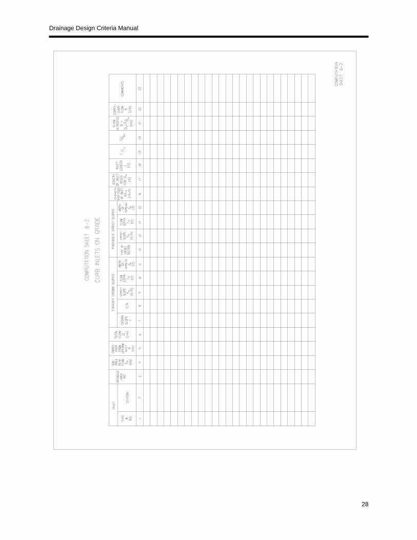
In order to facilitate the computations required in determining the various hydraulic properties for curb inlets on grade, Computation Sheet 6-2 has been prepared.
Column 1 Inlet Type and number.
Column 2 Location of inlet by station number.
Column 3 Drainage Area designation of area entering between the
previous pick up point and the inlet being designed.
Column 4 Peak Discharge (Qp) from area of Column 3.
Column 5 Carry-over flow (q) which has been passed by the last
preceding inlet to the inlet under consideration.
Column 6 Total gutter flow (Qo) in c.f.s. For inlets other than the
first inlet in the system, total gutter flow is the sum of the
runoff from the contributing area plus carry-over flow
from the inlet or inlets upstream. Column 4 plus
Column 5.
Column 7 Reciprocal of the pavement cross slope for pavements
with straight crown slopes.
Column 8 Reciprocal of the pavement cross slope (Z) divided by
the pavement roughness coefficient (n) .
Column 9 Slope of approach gutter (So) in ft. per ft.
Column 10 Depth of gutter flow "Yo" in approach gutter from
Figure 5-3. Figure 5-4. or Appendix B solution or direct from Manning’s
equation for triangular gutters:
Yo = 1.245 (Q 3/8
)[n3/8
/S3/16
] [1/Z]3/8

Drainage Design Criteria Manual
27
Column 11 Spread of water (Sp) or width of ponding in the gutter measured from the
face of curb. Column 7 times Column 10 (Figure 5-3 or Appendix B).
Column 12 Width of street and height of parabolic crown.
Column 13 Slope of approach gutter (So) in ft. per ft.
Column 14 Depth of gutter flow "Yo" in approach gutter from Figure 5-4 or Appendix
B.
Column 15 Spread of water (Sp) or width of ponding in the gutter
measured from face of curb from Figure 5-4 or Appendix B.
Column 16 Discharge in cubic feet per second (Q) which will be intercepted by an
inlet one foot in length for a given depth of flow in the approach gutter
(Yo). Determined from Figure 6-4 or from the solution of the following
equation:
Q/Lo = 0.7[1/yo] [(H)5/2
-(a)5/2
]
Column 17 Length of inlet (Lo) in feet which is necessary to intercept a given
discharge Qo. Column 6 divided by Column 16.
Column 18 Actual length (L) in feet of inlet which is to be provided.
Column 19 Ratio of the length of inlet provided (L), to the length of the inlet required
for 100% interception (Lo). Column 18 divided by Column 17.
Column 20 Percentage of discharge intercepted by the inlet in question determined
from Figure 6-5 using the values determined in Column 19 and Column
10 or Column 14.
Column 21 Discharge (Q) in cubic feet per second which the inlet in question
actually intercepts. Column 6 times Column 20.
Column 22 Carry-over flow (q) is the amount of water which passes any inlet, and is
the difference between the total flow (Qo) of Column 6 and the
intercepted flow (Q) of Column 21.
Drainage Design Criteria Manual
28

Drainage Design Criteria Manual
29

Drainage Design Criteria Manual
30

Drainage Design Criteria Manual
31
D. Storm Drain Pipe Design
1. Design Frequency
Pipe Design: flood mitigation storm event
2. Design Criteria
a) Storm drain systems capable of conveying the flood mitigation storm event are required when water spread, intersection cross flow, and lot to lot drainage flow limits are exceeded. Closed pipe systems shall be required for discharges up to and including 300 cfs.
b) Pipe material shall be reinforced concrete for all pipe sizes 48” and larger in diameter with appropriate bedding and class type depending on cover. Pipe material for pipe sizes less than 48” shall be reinforced concrete or aluminized steel Type II Ultra Flow or equivalent with proper backfill and cover.
c) The maximum hydraulic gradient shall not produce a velocity that exceeds 15 feet per second (fps). Table 3.8 shows the desirable velocities for most storm drainage design. Storm drains shall be designed to have a minimum mean velocity flowing full at 2.5 fps.
Table 3.8 Desirable Velocity in Storm Drains
Description Maximum Desirable Velocity
Culverts (All types) 15 fps
Inlet laterals No Limit
Collectors (up to 24”) 15 fps
Mains (Larger than 24”) 12 fps
d) The minimum desirable physical slope shall be 0.5% or the slope that will produce a velocity
of 2.5 feet per second when the storm sewer is flowing full, whichever is greater.
e) The potential hydraulic grade line elevation shall not exceed ground elevation or the gutter flow line, whichever is lowest.
f) Access manholes are required at intermediate points along straight runs of closed conduits. Table 3.9 gives maximum spacing criteria.
Table 3.9 Access Manhole Spacing Criteria
Pipe Size (inches) Maximum Spacing (feet)
18-36 600
42” and Larger 1000
g) Manholes shall also be located at:
pickup points having two (2) or more curb inlets or laterals at the same relative point of a street or alley;
trunk line size changes for pipes greater than twenty-four (24) inches; or pipe size difference of 6 inches or greater;

Drainage Design Criteria Manual
32
pipe junctions having any pipe 36” and larger;
grade changes;
the upstream end of the storm drain system;
Bends greater than 30 degrees and pipe junctions greater than 45 degrees;
At the connection point of public and private storm sewer pipes or boxes.
h) The minimum storm drain pipe diameter shall be eighteen (18) inches.
i) Pipe diameters shall not normally decrease downstream.
j) Pipe crowns (soffits) at change in sizes should be set at the same elevation.
k) Pipe collars may be used when pipe size changes are required on trunk lines for 24-inch
diameters or less.
l) Laterals shall be connected to collector or main lines using manholes or manufactured wye
connections. Special situations may require laterals to be connected to the trunk lines by a
cut-in (punch-in), and such cut-ins must be approved by the City Engineer.
m) Vertical curves in the conduit will not be permitted and horizontal curves will be permitted only
in specific cases with the approval of the City Engineer. Radius pipe shall be installed for
curves with radii between 100-ft and 500-ft.
E. Parking Lot Design
Parking lots shall be designed for the flood mitigation storm not to exceed top of curb with maximum ponding at low points of one (1) foot. The flood mitigation storm shall be contained on-site or within dedicated easements.
3.4.3 Hydraulic Design Criteria for Structures
A. Introduction
This section is intended to provide design criteria and guidance on several on-site flood mitigation system components, including culverts, bridges, vegetated and lined open channels, storage design, outlet structures, and energy dissipation devices for outlet protection.
B. Open Channels
1. Design Frequency
a) Open channels, including all natural or improved channels, swales, and ditches shall be designed for the flood mitigation storm event
2. Design Criteria
a) Constructed or improved channels shall be designed with a 10-ft minimum concrete pilot channel section and concrete side slope protection up to the streambank protection elevation.
b) All channels with contributing drainage basins larger than one square mile shall remain in their natural condition.

Drainage Design Criteria Manual
33
c) All channels with contributing drainage basins less than one square mile shall maintain a natural stream buffer of 50 feet on either side of the stream if identified on the environmentally sensitive area (ESA) map. For drainage areas without a stream buffer identified on the ESA map, and less than one square mile, erosive velocities will dictate whether an earthen or fully lined concrete channel is needed.
d) All improved channels shall be designed to carry the flood mitigation flow and shall have one foot of freeboard as illustrated in Figure 8-1. Freeboard requirements at bends in all improved channels shall be the greater of the following:
a. 1. One (1) foot or
b. 2. Ten (10) percent of the flow depth
e) At a minimum, channels that require concrete lining shall be lined up to an elevation of the water surface resulting from the flood mitigation storm.
f) Unlined improved channels that contain bends may be required to be reinforced if maximum permissible velocities are exceeded.
g) Unlined improved channels shall have side slopes no steeper than 4:1 and concrete lined channels shall have side slopes no steeper than 2:1.
h) Geotechnical investigations will be required for open channel designs, except in cases where the City Engineer deems it not necessary.
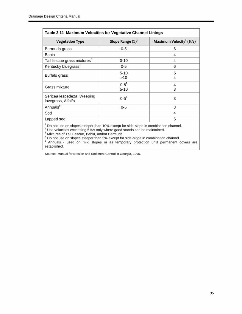
i) For vegetative channels, flow velocities within the channel shall not exceed the maximum permissible velocities given in Tables 3.10 and 3.11.
j) If relocation of a stream channel is unavoidable, the cross-sectional shape, meander, pattern, roughness, sediment transport, and slope shall conform to the existing conditions insofar as practicable. Energy dissipation will be necessary when existing conditions cannot be duplicated.
k) Streambank stabilization shall be provided, when appropriate, as a result of any stream disturbance such as encroachment and shall include both upstream and downstream banks as well as the local site.
l) HEC-RAS, or similarly capable software approved by the entity with jurisdiction, shall be used to confirm the water surface profiles in open channels.
m) The final design of artificial open channels shall be consistent with the velocity limitations for the selected channel lining. Maximum velocity values for selected lining categories are presented in Table 3.10.
n) Seeding and mulch shall only be applied with use of erosion control blanket when the design velocity exceeds the allowable velocity for bare soil. Velocity limitations for vegetative linings are reported in Table 3.11. Vegetative lining calculations and stone riprap procedures are presented in Section 3.2 of the Hydraulics Technical Manual.
The design of stable rock riprap lining depends on the intersection of the velocity (local boundary shear) and the size and gradation of the riprap material. More information on calculating acceptable riprap velocity limits is available in Section 3.2.7 of the Hydraulics Technical Manual.

Drainage Design Criteria Manual
34
Table 3.10 Roughness Coefficients (Manning’s n) and Allowable Velocities for Natural Channels
Channel Description Manning’s n Max. Permissible Channel Velocity
(ft/s)
MINOR NATURAL STREAMS
Fairly regular section
1. Some grass and weeds, little or no brush 0.030 3 to 6
2. Dense growth of weeds, depth of flow materially greater than weed height
0.035 3 to 6
3. Some weeds, light brush on banks 0.035 3 to 6
4. Some weeds, heavy brush on banks 0.050 3 to 6
5. Some weeds, dense willows on banks 0.060 3 to 6
For trees within channels with branches submerged at high stage, increase above values by
0.010
Irregular section with pools, slight channel meander, increase above values by
0.010
Floodplain – Pasture
1. Short grass 0.030 3 to 6
2. Tall grass 0.035 3 to 6
Floodplain – Cultivated Areas
1. No crop 0.030 3 to 6
2. Mature row crops 0.035 3 to 6
3. Mature field crops 0.040 3 to 6
Floodplain – Uncleared
1. Heavy weeds scattered brush 0.050 3 to 6
2. Wooded 0.120 3 to 6
MAJOR NATURAL STREAMS
Roughness coefficient is usually less than for minor streams of similar description on account of less effective resistance offered by irregular banks or vegetation on banks. Values of “n” for larger streams of mostly regular sections, with no boulders or brush
Range from 0.028 to
0.060 3 to 6
UNLINED VEGETATED CHANNELS
Clays (Bermuda Grass) 0.035 5 to 6
Sandy and Silty Soils (Bermuda Grass) 0.035 3 to 5
UNLINED NON-VEGETATED CHANNELS
Sandy Soils 0.030 1.5 to 2.5
Silts 0.030 0.7 to 1.5
Sandy Silts 0.030 2.5 to 3.0
Clays 0.030 3.0 to 5.0
Coarse Gravels 0.030 5.0 to 6.0
Shale 0.030 6.0 to 10.0
Rock 0.025 15
For natural channels with specific vegetation type, refer to Table 3.11 for more detailed velocity control.
Drainage Design Criteria Manual
35
Table 3.11 Maximum Velocities for Vegetative Channel Linings
Vegetation Type Slope Range (%)1 Maximum Velocity2 (ft/s)
Bermuda grass 0-5 6
Bahia 4
Tall fescue grass mixtures3 0-10 4
Kentucky bluegrass 0-5 6
Buffalo grass 5-10 >10
5 4
Grass mixture 0-5
1
5-10 4 3
Sericea lespedeza, Weeping lovegrass, Alfalfa
0-54 3
Annuals5 0-5 3
Sod 4
Lapped sod 5
1 Do not use on slopes steeper than 10% except for side-slope in combination channel.
2 Use velocities exceeding 5 ft/s only where good stands can be maintained.
3 Mixtures of Tall Fescue, Bahia, and/or Bermuda
4 Do not use on slopes steeper than 5% except for side-slope in combination channel.
5 Annuals - used on mild slopes or as temporary protection until permanent covers are
established.
Source: Manual for Erosion and Sediment Control in Georgia, 1996.

Drainage Design Criteria Manual
36

Drainage Design Criteria Manual
37
3.4.4 Channel Drop Strutures
Sloping channel drops are permitted and are required to have a maximum slope of 4:1. Vertical channel drops are not permitted.
The flow velocities in the channel upstream and downstream of the drop structure need to satisfy the permissible velocities allowed for channels (Table 3.10). The velocities shall be checked for flows produced by the streambank protection and flood mitigation frequency events.
An apron shall be constructed immediately upstream of the chute or stilling basin to protect against the increasing velocities and turbulence which result as the water approaches the drop structure. The apron shall extend at least five (5) feet upstream of the point where flow becomes supercritical. In no case shall the length of the upstream apron be less than ten (10’) feet.
An apron shall be constructed immediately downstream of the chute or stilling basin to protect against erosion due to the occurrence of the hydraulic jump. The apron shall extend a minimum of ten (10’) feet beyond the anticipated location of the jump.
The design of drop structures is based on the height of the drop, the normal depths upstream and downstream of the drop structure and discharge.
When used, channel drop structures shall be located near bridges or culverts, as directed by the City Engineer.
The location of the hydraulic jump should be determined based on the upstream and downstream flow depths and channel slopes.
The length of the hydraulic jump should be calculated to determine the length of the downstream apron required to prevent erosion.
3.4.5 Maintenance Access
Access roads and/or ramps shall be provided for all channels to allow for maintenance of the channels. Access roads shall have a width of at least fifteen (15) feet and a cross slope no greater than 1/4-inch per foot. Access ramps shall be at least ten (10) feet wide and shall have a vertical grade no steeper than 6:1.
For all channels, access shall be provided by an access road adjacent to the channel. If the channel depth exceeds four (4) feet an access road will be required on both sides of the channel.

Drainage Design Criteria Manual
38
3.5 Culverts
Culverts are cross drainage facilities that transport runoff under roadways or other improved areas.
Design Frequency
Culverts shall be designed for the flood mitigation storm . Consideration when designing culverts includes: roadway type, tailwater or depth of flow, structures, and property subject to flooding, emergency access, and road replacement costs.
The flood mitigation storm shall be routed through all culverts to be sure building structures (e.g., houses, commercial buildings) are not flooded or increased damage does not occur to the highway or adjacent property for this design event.
Design Criteria
Velocity Limitations
The maximum velocity shall be consistent with channel stability requirements at the culvert outlet.
The maximum allowable velocity is 15 feet per second, but outlet protection shall be provided where discharge velocities will cause erosion conditions.
To ensure self-cleaning during partial depth flow, a minimum velocity of 2.5 feet per second is required for the streambank protection storm when the culvert is flowing partially full.
Headwater Limitations
The allowable headwater is the depth of water that can be ponded at the upstream end of the culvert during the flood mitigation storm event, which will be limited by one or more of the following constraints or conditions:
1. Headwater will be non-damaging to upstream property.
2. Culvert headwater plus 12 inches of freeboard shall not exceed top of curb or pavement for low point of road over culvert, whichever is lower.
Tailwater Considerations
If the culvert outlet is operating with a free outfall, the critical depth and equivalent hydraulic grade line shall be determined.
For culverts that discharge to an open channel, the stage-discharge curve for the channel must be determined. See Section 2.1.4 of the iSWM Hydraulics Technical Manual on methods to determine a stage-discharge curve.
If an upstream culvert outlet is located near a downstream culvert inlet, the headwater elevation of the downstream culvert will establish the design tailwater depth for the upstream culvert.
If the culvert discharges to a lake, pond, or other major water body, the expected flood mitigation storm event of the particular water body will establish the culvert tailwater.
Other Criteria
Culvert skews shall not exceed 30 degrees as measured from a line perpendicular to the roadway centerline without approval.
Erosion, sediment control, and velocity dissipation shall be designed in accordance with Section 4.0 of the Hydraulics Technical Manual.

Drainage Design Criteria Manual
39
3.6 Bridges
Design Frequency
Flood mitigation storm for all bridges Design Criteria
A freeboard of one-foot shall be maintained between the computed design water surface and the low chord of all bridges.
Design guidance is located in Section 3.4 of the Hydraulics Technical Manual.
3.7 Detention Structures
Design Frequency Detention structures shall be designed for the four storms (water quality, streambank protection, conveyance, and flood mitigation storms) for the critical storm duration that results in the maximum (or near maximum) peak flow. Design Criteria
Dry detention basins are sized to temporarily store the volume of runoff required to provide flood protection up to the flood mitigation storm.
Routing calculations must be used to demonstrate that the storage volume and outlet structure configuration complies with Section 3.3.2 of the Drainage Design Criteria Manual. Water Quality storage volume is not permitted to count toward the required storage volume for the other three storm events. See Section 1.0 of the Water Quality Technical Manual and Section 2.0 of the Hydraulics Technical Manual for procedures on the design of detention storage.
Private Detention Basins shall be designed with a 10 foot wide maintenance access around the entire perimeter of the pond.
Public Detention Basins shall be designed with a 20 foot wide maintenance access around the entire perimeter of the pond.
No earthen (grassed) embankment slopes shall exceed 4:1.
A freeboard of 1 foot will be required between the flood mitigation storm water surface elevation and top of bank.
A calculation summary shall be provided on construction plans as found on computation sheet 10-1 or equivalent. For detailed calculations of unit hydrograph studies, a separate report shall be provided for review and referenced on the construction plans. Stage-storage-discharge values shall be tabulated and flow calculations for discharge structures shall be shown on the construction plans.
An emergency spillway shall be provided at the flood mitigation maximum storage elevation with sufficient capacity to convey the conveyance storm inflow rates with six inches of freeboard. Spillway requirements must also meet all appropriate state and Federal criteria.
All detention basins shall be stabilized against significant erosion.
Design calculations will be provided for all spillways and outlet structures.
Storage and dam safety design may be subject to the requirements of the Texas Dam Safety Program (see iSWM Program Guidance) based on the volume, dam height, and level of hazard.
Riprap-protected slopes shall be no steeper than 2:1.
Geotechnical slope stability analysis is recommended for slopes greater than 10 feet in height.
The emergency spillway shall be constructed of concrete, unless the City Engineer approves alternative materials.
The embankment crown width shall be at least 12-feet wide for public detention ponds and 8-ft wide for private detention ponds, and shall be determined based on a geotechnical investigation of the detention facility site.
Security fencing with a minimum height of 6 feet shall encompass the detention storage area if the velocity, depth, or slopes create a potentially dangerous condition. The fence shall be designed so as

Drainage Design Criteria Manual
40
to allow access for maintenance and so as not to restrict stormwater flow into or out of the detention basin. The requirements of this section only apply to publicly maintained ponds only.
A maintenance equipment access ramp shall be provided. The slope of the ramp shall not exceed 6:1 and the minimum width shall be 12 feet. Where deemed necessary by the City Engineer, an access ramp(s) shall be installed to allow maintenance of privately maintained ponds. Some of the conditions that would require an access ramp(s) for privately maintained ponds includes, but is not limited to, steep side slopes, retaining walls, or space constraints.
Bottom slopes should not be less than one (1%) percent.
Concrete pilot channel at least 10 feet wide, and a minimum slope of 0.5 percent shall be constructed in bottom of the detention pond. Privately maintained ponds shall have a concrete pilot channel with a minimum width of six (6) feet.
All private detention basins will require a Drainage and Detention Easement. The following note shall be inserted into the plat: "This plat is hereby adopted by the owner and approved by the City of Denton (called "City") subject to the following conditions that shall be binding upon the owners, their heirs, grantees, and successors. The Drainage and Detention Easement within the limits of this addition, shall remain open at all times and will be maintained in a safe and sanitary condition by the owners of the lot or lots that are traversed by or adjacent to the Drainage and Detention Easement. The City will not be responsible for the maintenance and operation of said easement or for any damage to private property or person that results from conditions in the easement, or for the control of erosion. No obstruction to the natural flow of storm water run-off shall be permitted by construction of any type of building, fence or any other structure within the Drainage and Detention Easement, as herein above defined, unless approved by the City. The owners shall keep the drainage and detention easement clear and free of debris, silt, and any substance that would result in unsanitary conditions or obstruct the flow of water. And, the City shall have the right of ingress and egress for the purpose of inspection and supervision of maintenance by the owners to alleviate any undesirable conditions that may occur. Furthermore, the City shall have the right, but not the obligation, to enter upon the above-described drainage and detention easement to remove any obstruction to the flow of water, after giving the owners written notice of such obstruction and owners fail to remove such obstruction. Should the City of Denton be compelled to remove any obstruction to the flow of water, after giving the owners written notice of such obstruction and owners fail to remove such obstruction, the City of Denton shall be reimbursed by the owners reasonable costs for labor, materials, and equipment for each instance. The natural drainage through the Drainage and Detention Easement is subject to storm water overflow and natural bank erosion to an extent that cannot be definitely defined. The City shall not be held liable for any damages of any nature resulting from the occurrence of these natural phenomena or resulting from the failure of any structure or structures, within the easement or otherwise."
A 3.5% inspection fee will be required to be paid to the City for the construction of all private detention basins.
Use of parking lot surface area as detention is not permitted.
3.7.1 Outlet Structures for Detention and Retention Structures
Design Frequency Water Quality Streambank protection storm Conveyance storm Flood mitigation storm
Design Criteria
Estimate the required storage volumes for water quality, streambank protection, conveyance storm,
and flood mitigation.
Outlet velocities shall be within the maximum allowable range based on channel material as shown in
Tables 3.10 and 3.11.

Drainage Design Criteria Manual
41
Design necessary outlet protection and energy dissipation facilities to avoid erosion problems
downstream from outlet devices and emergency spillway(s).
Perform buoyancy calculations for the outlet structure and footing. Flotation will occur when the
weight of the structure is less than or equal to the buoyant force exerted by the water.
Any outflow structure, which conveys water through the embankment in a conduit shall be reinforced
concrete, designed to support the external loads. The conduit shall withstand the internal hydraulic
pressure without leakage under full external load or settlement and must convey water at the design
velocity without damage to the interior surface of the conduit.
The minimum pipe size and box size shall meet the following requirements:
Outlet Pipe and Box Size
Discharge Pipe Length Minimum Pipe
Size
Minimum Box
Size
100 feet or less 18 inches 2 feet x 2 feet
Greater than 100 feet 36 inches 3 feet x 3 feet
Minimum opening of inlet shall be 6 inches in diameter or 6” x 6” square. Smaller inlet openings may be used with junction box and properly sized outlet structure.
Design guidance is located in Section 2.2 of the Hydraulics Technical Manual.

Drainage Design Criteria Manual
42

Drainage Design Criteria Manual
43
3.8 Energy Dissipation
All drainage system outlets, whether for closed conduits, culverts, bridges, open channels, or storage facilities, shall provide energy dissipation to protect the receiving drainage element from erosion.
Design Frequency
Flood mitigation storm Design Criteria
Energy dissipaters are engineered devices such as rip-rap aprons or concrete baffles placed at the outlet of storm water conveyance systems for the purpose of reducing the velocity, energy and turbulence of the discharged flow.
Erosion problems at culvert, pipe and engineered channel outlets are common. Determination of the flow conditions, scour potential, and channel erosion resistance shall be standard procedure for all designs.
Energy dissipaters shall be employed whenever the velocity of flows leaving a stormwater management facility exceeds the erosion velocity of the downstream area channel system.
Energy dissipater designs will vary based on discharge specifics and tailwater conditions.
Outlet structures shall provide uniform redistribution or spreading of the flow without excessive separation and turbulence.
Recommended Energy Dissipaters for outlet protection include the following:
Concrete or grouted rock rip-rap apron
Riprap outlet basins
Baffled outlets
Grade Control Structures
Design guidance is located in Section 4.0 of the Hydraulics Technical Manual.


![Internal - Luciano Chinellato · AnyOne® Internal è -P_[\YL 3L]LS 7YVZ[OLZPZ EZ Post Milling Abutment Angled Abutment CCM Abutment Temporary Abutment [Titanium] Temporary Abutment](https://img.pdfslide.net/doc/110x75/5c038f7909d3f2156d8cd7fd/internal-luciano-anyone-internal-e-pyl-3lls-7yvzolzpz-ez-post-milling.jpg)