Embed Size (px)
Citation preview
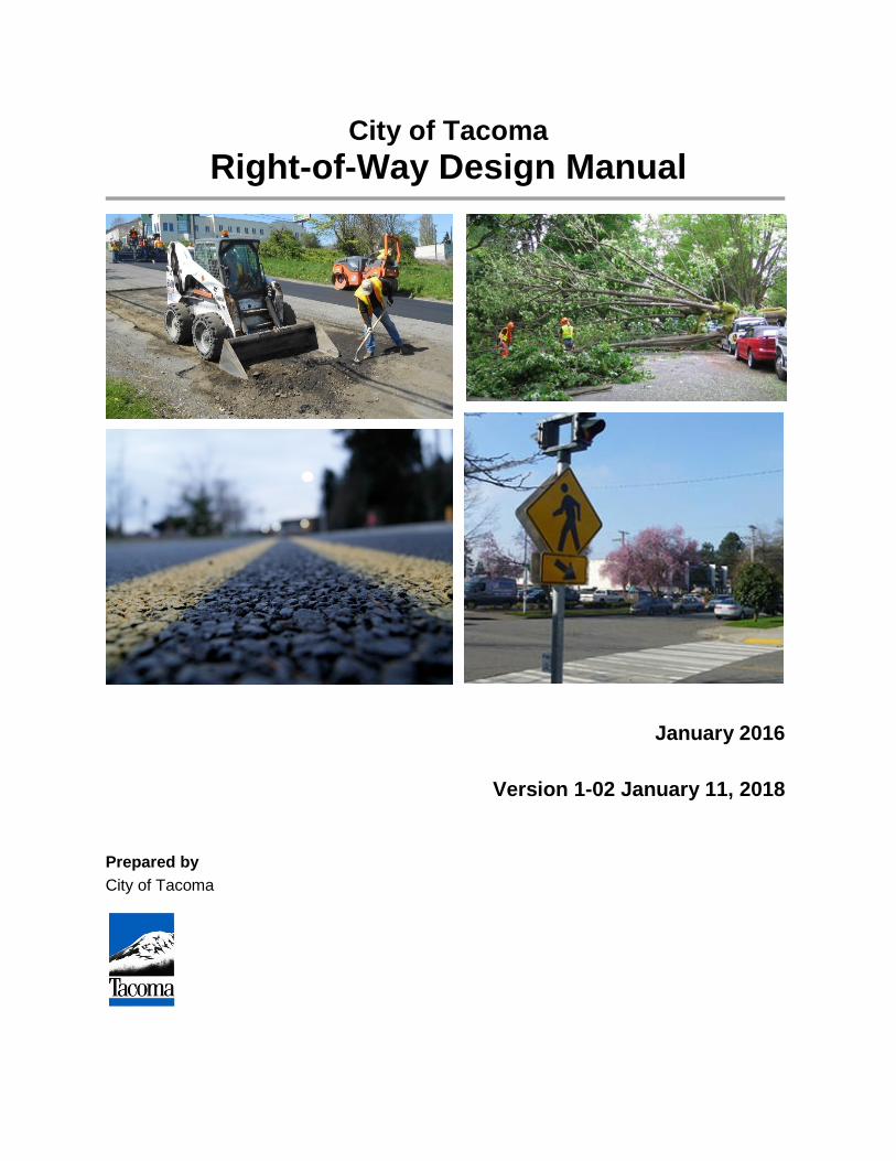
City of Tacoma Right-of-Way Design Manual
January 2016
Version 1-02 January 11, 2018
Prepared by City of Tacoma
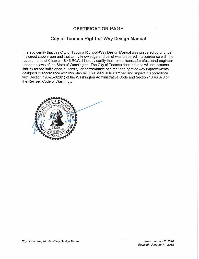
TABLE OF CONTENTS Table of Contents ..................................................................................... 1
Abbreviations / Acronyms ........................................................................ 2
Introduction and General Requirements ..................... 1-1 CHAPTER 1
Right-of-Way/Site Permitting and Local Improvement CHAPTER 2Districts 2-1
Site Development Permit and Right-of-Way CHAPTER 3Construction Plan Format ..................................................................... 3-1
Street Design ................................................................. 4-1 CHAPTER 4
Illumination .................................................................... 5-1 CHAPTER 5
Traffic Signalization ...................................................... 6-1 CHAPTER 6
Channelization and Signing .......................................... 7-1 CHAPTER 7
Pedestrian Facilities ...................................................... 8-1 CHAPTER 8
Tree and Vegetation Management ................................ 9-1 CHAPTER 9
Shared-Use Paths ....................................................... 10-1 CHAPTER 10
Stormwater and Wastewater Sewer Design .............. 11-1 CHAPTER 11
Water Plans ................................................................. 12-1 CHAPTER 12
Construction Related Permits and Easements ......... 13-1 CHAPTER 13
Definitions .................................................................................................. i
References ................................................................................................. i
City of Tacoma, Right-of-Way Design Manual Issued: January 7, 2016 i Revised: January 11, 2018
ABBREVIATIONS / ACRONYMS AASHTO American Association of State Highway and Transportation Officials AASHTO Policy American Association of State Highway and Transportation Officials’ A
Policy on Geometric Design of Highways and Streets ADA Americans with Disabilities Act ANSI American National Standards Institute APS Accessible Pedestrian Signals APWA American Public Works Association BMPs Best Management Practice BUG Backlight, Uplight, Glare CFR Code of Federal Regulations City City of Tacoma CSTC Crushed Surfacing Top Course CSBC Crushed Surfacing Base Course EIS Environmental Impact Statement FHWA Federal Highway Administration GSI Green Stormwater Infrastructure HDPE High Density Polyethylene HMA Hot Mix Asphalt IBC International Building Code IFC International Fire Code IES Illuminating Engineering Society ISA International Society of Arboriculture LZ Lighting Zone Manual City of Tacoma Right-of-Way Design Manual MEF Maximum Extent Feasible MoMaP Mobility Master Plan MUTCD Manual on Uniform Traffic Control Devices NEMA National Electrical Manufacturers Association Orange Book Department of Ecology Criteria for Sewage Works Design PAR Pedestrian Access Route PCPs Pedestrian Circulation Paths PVC Polyvinyl Chloride PROWAG Public Rights-of-Way Guidelines RCW Revised Code of Washington ROW Right-of-way RRFBs Rectangular Rapid Flashing Beacons SSD Stopping Sight Distance SEPA State Environmental Policy Act Side Sewer Manual City of Tacoma Side Sewer and Sanitary Sewer Availability Manual SWMM Stormwater Management Manual SWPPP Stormwater Pollution Prevention Plan TMC Tacoma Municipal Code UFM Urban Forest Manual WAC Washington Administrative Code WSDOT Washington State Department of Transportation
City of Tacoma, Right-of-Way Design Manual Issued: January 7, 2016 ii Revised: January 11, 2018
CHAPTER 1Introduction and General Requirements
INTRODUCTION ..................................................................................... 1-2
SECTION 1 Plans, References, and Specifications ........................ 1-2 1.1 References ...............................................................................................................1-2 1.2 Standard Specifications ............................................................................................1-2 1.3 Standard Plans .........................................................................................................1-3 1.4 Project Plans ............................................................................................................1-3 1.5 Exceptions to the Standards and Requirements .......................................................1-3
1
City of Tacoma, Right-of-Way Design Manual Issued: January 7, 2016 Chapter 1 1-1 Revised: January 11, 2018
INTRODUCTION
The City of Tacoma Right-of-Way Design Manual (Manual) shall apply to the construction of all street and right-of-way (ROW) improvements including stormwater and wastewater construction, street lighting, traffic signalization, landscaping, Americans with Disabilities Act (ADA) requirements, and channelization. The Manual provides the minimum technical standards required to construct improvements within the City of Tacoma ROW. This Manual is designed to be used in conjunction with other local, state, and federal rules, regulations, and design guidance as applicable to a given project. See References for a list of the most commonly referenced additional documents that will be necessary for design within the ROW.
Tacoma Municipal Code (TMC) Chapter 10.22 provides the authority to require the use of this Manual for certain projects.
The City of Tacoma (City) has developed this Manual to outline design criteria for City-owned streets and utilities as well as private accessways. The minimum technical standards described in this Manual help ensure public infrastructure is safe, effective, efficient, economical, and sustainable. City staff, private developers, and any other entity proposing construction within the public ROW or proposing construction of City-owned facilities shall use this Manual. Deviations from the standards within this Manual shall be based upon sound engineering practices and shall be reviewed and approved by appropriate City staff before implementation.
This Manual should be used by the design engineer as a tool prior to submitting plans for review. It should be considered a “living document” and is subject to updates and revisions. The Manual and any updates are available at www.cityoftacoma.org/designmanual.
The City became the first "Greenroads® Community" in June 2014, through adoption of Resolution No. 38945. This means that the City is committed to developing a policy for the City's roads and other transportation infrastructure in order to be models of environmental, economic, and social stewardship and by setting community goals of sustainable design, construction, and maintenance. See CHAPTER 4 for additional information concerning Greenroads® requirements.
SECTION 1 Plans, References, and Specifications
1.1 References References and portions of text from documents, ordinances, standards, and codes have been provided for convenience based on the current publication date of each reference. All references contained herein shall be superseded by the latest adopted or published respective reference.
1.2 Standard Specifications Projects shall use the most recent City adopted version of the Washington State Department of Transportation (WSDOT) Standard Specifications for Road, Bridge, and Municipal Construction (Standard Specifications) as supplemented or amended by the Washington State Chapter of the American Public Works Association (APWA); the City of Tacoma General Special Provisions; Work Order General Notes; general or site specific notes referenced on the plan set; other City design manuals or policies; or the design engineer’s site specific edits.
City of Tacoma, Right-of-Way Design Manual Issued: January 7, 2016 Chapter 1 1-2 Revised: January 11, 2018

1.3 Standard Plans City Standard Plans (also referred to as standard details) are included by reference in this Manual. Applicants shall reference and use the most recent version of the City Standard Plans when applicable for the work proposed. Standard plans applicable to a project shall be included on the plan set.
If a City Standard Plan does not exist, applicants shall use the most recent version of the WSDOT Standard Plans as supplemented or amended by the Washington State Chapter of the APWA; standard plans contained in other City design manuals or policies; standard details shown on the plan set; or the design engineer’s site specific details.
1.4 Project Plans Prior to any construction within the ROW, the extension of any public utility, or construction of improvements that will be owned and/or operated by the City, a complete plan set with associated technical reports shall be prepared by a professional engineer licensed in the State of Washington. Plans and reports shall be submitted to the City for review and approval. Applicants shall obtain all appropriate City permits and may be required to obtain additional state, federal, or other local jurisdiction permits depending upon project scope. Plans and specifications submitted shall be in conformance with this Manual and other applicable City standards. Reference CHAPTER 2 and CHAPTER 3 for more information on the permitting process and plan format respectively.
The applicant or design engineer is responsible for identifying and complying with all applicable local, state and federal regulatory requirements.
• The Governor’s Office for Regulatory Innovation and Assistance website is a useful tool for determining additional permitting requirements that may apply to a project.
• The City permitting website is a good tool for determining additional regulations that may be imposed by other City departments.
1.5 Exceptions to the Standards and Requirements Exceptions to this Manual may be requested to the City based upon specific project constraints. Alternative designs may be allowed if based on accepted standards of engineering practice and where specific project circumstances do not allow application of the standards and requirements of this Manual. Standards and requirements contained within this Manual may have specific procedures and requirements for requesting and granting exceptions. Contact the City department with jurisdiction over the requirement for information regarding a specific exception request. It will be the responsibility of the design engineer and/or applicant to submit all relevant data, calculations and figures as may be necessary to evaluate a request for exception. All approved exceptions shall be given in writing by the appropriate City department.
City of Tacoma, Right-of-Way Design Manual Issued: January 7, 2016 Chapter 1 1-3 Revised: January 11, 2018
CHAPTER 2Right-of-Way/Site Permitting and Local Improvement Districts
INTRODUCTION ..................................................................................... 2-3 Applicable Permits ...............................................................................................................2-3 Division of Permitting ...........................................................................................................2-3
SECTION 1 Authority and Permits ................................................... 2-3 1.1 Enforcement .............................................................................................................2-3 1.2 Provisions for Permit.................................................................................................2-3
SECTION 2 Initiation of a ROW Construction/Work Order Permit and/or Site Development Permit ........................................................... 2-4
2.1 Applying for a ROW Construction/Work Order Permit and/or Site Development Permit .......................................................................................................................2-4
2.2 Descriptions of ROW Construction/Work Order and Site Development Permits ........2-4 2.2.1 Site Development Minor Permit ........................................................................... 2-4 2.2.2 Site Development Major Permit ........................................................................... 2-4 2.2.3 ROW Construction Permit .................................................................................... 2-5 2.2.4 Work Order Permit ............................................................................................... 2-5 2.2.5 Performance Bonding .......................................................................................... 2-5
SECTION 3 Review Process ............................................................. 2-7 3.1 Coaching or Intake Meeting ......................................................................................2-7 3.2 Plan Review and Resubmittals .................................................................................2-7 3.3 Prior to Permit Approval ............................................................................................2-7
SECTION 4 The Approval Process ................................................... 2-7 4.1 Approval of the ROW Construction/Work Order Permit and Site Development
Permit Plan Set .........................................................................................................2-7 4.2 Distribution of Approved Plans ..................................................................................2-7 4.3 Revisions ..................................................................................................................2-7
SECTION 5 Applicant/Contractor Responsibilities ......................... 2-8 5.1 Pre-Construction Meeting .........................................................................................2-8 5.2 Obtaining a Permit for Construction ..........................................................................2-8 5.3 Applicant Responsibilities .........................................................................................2-8
SECTION 6 Bonding Requirements ................................................. 2-8 6.1 ROW Bond ...............................................................................................................2-8 6.2 Performance Bond ....................................................................................................2-8
SECTION 7 Construction and Inspection ........................................ 2-8 7.1 Work Authorized Under the Permit(s) .......................................................................2-8
2
City of Tacoma, Right-of-Way Design Manual Issued: January 7, 2016 Chapter 2 2-1 Revised: January 11, 2018

SECTION 8 Closure of the ROW Construction/Work Order Permit and Site Development Permit ............................................................... 2-9
8.1 Construction Deficiency List Items ............................................................................2-9 8.2 Record Drawings ......................................................................................................2-9 8.3 Permit Closeout ........................................................................................................2-9 8.4 Permit Expiration ......................................................................................................2-9
SECTION 9 Local Improvement Districts ......................................... 2-9 9.1 Local Improvement District Definition ...................................................................... 2-10 9.2 Starting an Local Improvement District ................................................................... 2-10 9.3 Advisory Survey ...................................................................................................... 2-10 9.4 Formation Hearing and the Initiation of Construction .............................................. 2-10 9.5 Costs/Methods of Payment ..................................................................................... 2-10 9.6 Financial Assistance ............................................................................................... 2-11
City of Tacoma, Right-of-Way Design Manual Issued: January 7, 2016 Chapter 2 2-2 Revised: January 11, 2018
INTRODUCTION
This chapter focuses on the City permitting process that private developers must follow for constructing improvements in the City ROW. The alternative to the permitting process is to form a Local Improvement District. A description of the Local Improvement District process can be found in Section 9 of this chapter.
Applicable Permits A ROW Construction/Work Order Permit and a Site Development Permit are mechanisms used by the City for the review, approval, and inspection of privately designed plans for the construction of infrastructure, both private and City-owned. City-owned infrastructure includes, but is not limited to wastewater and stormwater sewer infrastructure, roadways, street lighting, traffic signals, and other traffic control devices and associated appurtenances. Privately owned infrastructure includes, but is not limited to wastewater laterals (side sewers), stormwater systems laterals, paving, private accessways, private streets (such as sidewalks and driveways) and associated appurtenances.
Division of Permitting The City separates the construction of the facilities and infrastructure listed in the above paragraph into two separate categories: public improvements and private improvements. Projects generally include a public and private improvement component; therefore, both a Site Development Permit and a ROW Construction/Work Order Permit will be required. See Tip Sheets for additional detailed information regarding applicable permits. These are available online or at the Permit Intake Center located on the third floor of the Tacoma Municipal Building, 747 Market Street, Tacoma, WA 98402.
SECTION 1 Authority and Permits
1.1 Enforcement TMC requires that any proposed improvements within the City ROW require permit(s) and that the City shall approve all plans and associated permit(s). The TMC also requires permits for onsite construction.
Some of the work covered under this Manual may require multiple City permits, reviews, and approvals. Any questions regarding permits, approvals, and agreements shall be directed to the Planning and Development Services Department at Tacoma Permits or (253) 591-5030.
1.2 Provisions for Permit The person, firm or corporation to whom the permit is issued shall conform to the City’s general special provisions and design standards following vesting protocols if applicable and with additional conditions and provisions as may be prescribed by the Director of Public Works, Director of Environmental Services, Director of Planning and Development Services or their designated agents.
City of Tacoma, Right-of-Way Design Manual Issued: January 7, 2016 Chapter 2 2-3 Revised: January 11, 2018
SECTION 2 Initiation of a ROW Construction/Work Order Permit and/or Site Development Permit
See Figure 2-1 for a flowchart describing the permitting process.
2.1 Applying for a ROW Construction/Work Order Permit and/or Site Development Permit To start the permitting process, an applicant shall provide the following electronically to the Planning and Development Services Department:
• A complete application. All correspondence from the City will be sent to the individual listed as the contact person on the form.
• A detailed/engineered plan set as defined by Tip Sheets. This plan set must be standalone and independently convey the scope of work without further explanation.
• A cost estimate for site work.
• A copy of the conditions of improvement if available. This may be a Hearing Examiner's report, recorded plat, concomitant agreement, short plat report or recorded short plat, a letter from the Site Development Group staff or a list of requirements placed on a commercial building permit application, as applicable.
• Payment of all applicable permit fees.
• Electronic copies of all required reports and associated documents, including but not limited to Stormwater Site Plan, Stormwater Pollution Prevention Plan (SWPPP), and Geotechnical Report.
2.2 Descriptions of ROW Construction/Work Order and Site Development Permits The City reserves the right to designate the classification of the ROW Construction Permits.
2.2.1 Site Development Minor Permit The Site Development Minor Permit is intended to be used for a single family/duplex residential building lot. This permit will include all scopes of work for the building site including: grading, paving, stormwater and wastewater facilities, and any utility work. The Site Development Minor Permit is a fee based permit and includes all review and inspections necessary to complete the project work onsite. Depending on the scope of work, an engineered plan set may be necessary to obtain City approval. If any portion of the work is proposed within the ROW then a separate ROW Construction/Work Order Permit will be required. The applicant may combine the onsite and offsite work into one combined plan set, and the City will review all work under that plan set. Additional services such as relocation of streetlights will be an additional fee. A performance bond will be required for any ROW work valued over $15,000, as determined by the City.
2.2.2 Site Development Major Permit The Site Development Major Permit is intended to be used for all commercial, industrial, wetland development, and plat/short plat site work. This permit will include all scopes of work for the building site including: grading, paving,
City of Tacoma, Right-of-Way Design Manual Issued: January 7, 2016 Chapter 2 2-4 Revised: January 11, 2018
stormwater and wastewater facilities, and any utility work. The Site Development Major Permit is a variable fee based or actual cost based permit depending on the scale/complexity of the project as established by the fee code. Engineered plans are almost always required for all levels of the Site Development Major Permit. If work is proposed within the ROW then a separate ROW Construction/Work Order Permit will be required. The applicant may combine the onsite and offsite work into one combined plan set, and the City will review all work under that plan set. As with the Site Development Minor Permit, all additional services shall be billed at an at cost basis. A performance bond will be required for all ROW work.
2.2.3 ROW Construction Permit The ROW Construction Permit is intended to be used for ROW work not associated with a new development or redevelopment project, or as a related permit to the Site Development Permit. The cost for the ROW construction is based on the scope of work and may be a flat fee, or if deemed necessary by the City may be billed to the applicant at an at cost basis. Engineered plans may be required at the discretion of the Site Development Group reviewer. A performance bond will be required for all ROW work completed under a ROW Construction Permit in conjunction with the Site Development Permit.
2.2.4 Work Order Permit The Work Order Permit is intended to be used for ROW work not associated with a new development or redevelopment project, or as a related permit to the Site Development Permit. The cost for the ROW construction plan review and inspection fees is billed to the applicant at an at cost basis. Engineered plans are required based on the scope of work as determined by the Site Development Group reviewer. A performance bond will be required for all work completed within the City ROW.
2.2.5 Performance Bonding The applicant may be required to post a bond, provide an assignment of funds or otherwise allocate funds for the construction of required improvements. City staff will work with the applicant to determine the appropriate bond amount for a given project. The bond amount must provide adequate funds for the City to administer the contract if necessary. City Tip Sheet G-220 provides additional information regarding performance bonds for work within the ROW.
• Performance Bonds for Plat Approval: When applying for final plat/short plat approval prior to constructing the required improvements, the City will require a performance bond for the construction of the improvements or the remaining required improvements per TMC 13.04.090 or TMC 13.04.100.
• Bonding for Previously Platted Property: Lots on previously platted property will require a bond for the required improvements prior to approval of the ROW Construction/Work Order Permit plans.
City of Tacoma, Right-of-Way Design Manual Issued: January 7, 2016 Chapter 2 2-5 Revised: January 11, 2018
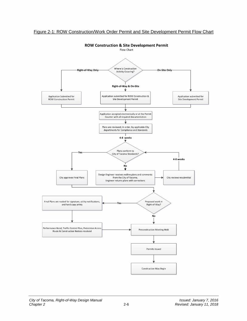
Figure 2-1: ROW Construction/Work Order Permit and Site Development Permit Flow Chart
City of Tacoma, Right-of-Way Design Manual Issued: January 7, 2016 Chapter 2 2-6 Revised: January 11, 2018
SECTION 3 Review Process
3.1 Coaching or Intake Meeting Prior to submitting the first set of plans, the applicant or design engineer may elect to schedule a coaching or intake meeting with City staff.
3.2 Plan Review and Resubmittals Upon submittal, the plans will be reviewed for conformance with applicable local, state, and federal requirements. The City will provide consolidated comments to the contact listed on the application form. The applicant shall make changes to the proposed project based upon the City’s comments. Several review iterations may be required. The City will review projects in the order they are received.
3.3 Prior to Permit Approval Upon first review, the applicant shall be informed if any additional items are required including the in lieu of assessment release form, covenant and easement agreement and private property permanent or temporary easements as applicable. Prior to approval of the plans, the applicant must complete all required documents and plan changes. During the course of project review, changes made by the applicant may affect which forms and easements are required. The applicant shall be informed of the need for additional items after each review period.
SECTION 4 The Approval Process
4.1 Approval of the ROW Construction/Work Order Permit and Site Development Permit Plan Set Once the City has determined the plans conform with all applicable regulations, a final copy of the plan set and associated reports shall be submitted to the City.
4.2 Distribution of Approved Plans A reproducible set will be transmitted to the design engineer or applicant with written direction as to the remaining permit and preconstruction process. In addition, a copy of the approved plans will be transmitted to the various utilities. If ROW work is included, the plans will be uploaded to the City website.
4.3 Revisions Any change to the approved plans shall be submitted for approval to the Site Development Group staff prior to implementation in the field. Some minor changes may be verbally approved in the field by the City Inspection staff and the change in design shall be noted on the record drawing plans submitted at the conclusion of the project.
In order to revise an approved plan, the design engineer shall make the changes and identify the revision as such in the title block of an approved plan set. The revision number, description and date shall be identified within the revision block located in the title block.
City of Tacoma, Right-of-Way Design Manual Issued: January 7, 2016 Chapter 2 2-7 Revised: January 11, 2018
SECTION 5 Applicant/Contractor Responsibilities
5.1 Pre-Construction Meeting Prior to permit issuance and the start of work, the applicant shall contact the Site Development Group staff at (253) 591-5760 to coordinate and schedule a preconstruction meeting.
5.2 Obtaining a Permit for Construction Upon approval of the plans, paying all permit fees, and holding the pre-construction meeting, a contractor satisfying the following criteria may use the approved plans to obtain the ROW Construction/Work Order or Site Development Permit. The contractor shall:
• Be licensed and bonded in the State of Washington;
• Possess a City of Tacoma Business License;
• Provide approved traffic control plans for street and pedestrian accessible routes;
• Provide copy of notification to impacted properties letter; and
• Obtain a ROW Bond as outlined in Section 6.1 of this chapter, if applicable.
5.3 Applicant Responsibilities • Comply with all applicable city, state, and federal requirements.
• If applicable, obtain a performance bond for the value of work as outlined in Section 6.2 of this chapter.
SECTION 6 Bonding Requirements
6.1 ROW Bond The contractor shall deliver to the City, prior to the issuance of the permit, a street obstruction/ROW bond in the sum of no less than $15,000, in a form to be approved by the City Attorney and with surety approved by the Director of Finance (TMC 10.22).
6.2 Performance Bond The applicant or contractor shall deliver a separate bond to the City, prior to the issuance of a ROW Construction/Work Order Permit, in the sum equal to the value of the work to be performed, but, in any event, not less than $15,000, in a form to be approved by the City Attorney and with surety approved by the Director of Finance.
SECTION 7 Construction and Inspection
The TMC allows the City to inspect all proposed work. Failure to comply with the provisions set forth in this Manual or the approved plans may result in a stop work order, requirements for removal and replacement of unacceptable work, seizure of bond, or other penalties as established by ordinance
7.1 Work Authorized Under the Permit(s) After the pre-construction meeting has been held and the applicable permit(s) has been issued, the contractor may begin construction. The contractor, developer, or their agents
City of Tacoma, Right-of-Way Design Manual Issued: January 7, 2016 Chapter 2 2-8 Revised: January 11, 2018
must have an approved set of plans onsite at all times during construction. Work outside of the scope dictated by the approved plan set will require a revision (see Section 4.3 of this chapter) to the plan set or shall be constructed under separate permit(s).
It is the responsibility of the permitee to ensure that all necessary inspections are called for in advance and approved by City Inspection staff.
All specific inspections, test measurements or actions required for all work and materials are set forth in other chapters of this Manual; the City Standard Plans; Work Order General Notes; WSDOT Standard Specifications; City General Special Provisions; and Stormwater Management Manual (SWMM). Material and performance tests (e.g., compaction, compression tests for concrete, soil reports, etc.) shall be performed at no cost to the City.
SECTION 8 Closure of the ROW Construction/Work Order Permit and Site Development Permit
8.1 Construction Deficiency List Items Prior to final acceptance, the City shall provide the contractor with a construction deficiency list. The deficiency list will contain a complete list of required work to be performed to grant final acceptance.
8.2 Record Drawings Prior to permit closure, record drawings shall be provided to the Site Development Group. The criteria for creating the record drawings are outlined in the Record Drawing Criteria or the SWMM, as applicable.
8.3 Permit Closeout Upon completion, the City will initiate closure and will release any holds on assignment of funds or performance bonds. Conversely, if the account contains an outstanding balance, the City will bill the applicant for the funds necessary to cover the expenses already incurred by the City.
8.4 Permit Expiration If after permit approval construction does not begin within 24 months, then the plan approval expires for the ROW Construction/Work Order Permit. The applicant will need to reapply and start the permitting process over. The ROW Construction/Work Order Permit will be closed and the account settled accordingly.
SECTION 9 Local Improvement Districts
One alternative to the ROW Construction/Work Order Permit and Site Development Permit process is to form a Local Improvement District. The following is a summary of the Local Improvement District process and provides answers to some common questions. The Local Improvement Districts Policy was updated as outlined in Resolution No. 37659. Contact the Local Improvement District Administrator at (253) 591-5522 for additional information concerning the Local Improvement District process.
City of Tacoma, Right-of-Way Design Manual Issued: January 7, 2016 Chapter 2 2-9 Revised: January 11, 2018

9.1 Local Improvement District Definition A Local Improvement District provides a process for public financing of public infrastructure projects where property owners share the cost of street and alley paving, wastewater sewer extensions, street lighting, water mains, sidewalks and/or underground wiring. Costs to the owners are deferred until the project is complete. A Local Improvement District requires support from 50 percent or more of the abutting properties willing to sign an advisory survey. Upon receipt by the Public Works Department of a valid survey, the City will consider the formation of a Local Improvement District when the benefits from the improvements outweigh the total cost of the improvements. Each property owner pays an amount proportional to the benefits that they receive for each property they own.
9.2 Starting an Local Improvement District An individual interested in a Local Improvement District should contact either the administrator at (253) 591-5522 or a representative at (253) 591-5338 and request a Local Improvement District advisory survey packet. City staff will prepare an estimate for the requested improvement(s) and provide a Local Improvement District packet which includes an advisory survey for circulation within the neighborhood. The requestor is responsible for circulating the advisory survey to gage support from the property owners within the proposed improvement area. Owners in favor of the proposed improvement would indicate their support by signing the advisory survey.
9.3 Advisory Survey The advisory survey is a non-binding request to the City Council where property owners representing at least 50 percent of the properties within the proposed Local Improvement District show their support of the proposed improvement. Upon receipt of an adequate advisory survey, a public hearing is scheduled to verify the level of support.
9.4 Formation Hearing and the Initiation of Construction The formation hearing allows property owners within the boundaries to ask questions about the proposed improvement and to question what impacts, if any, the proposed project would have to their property. Upon completion of the formation hearing, the Hearing Examiner will issue a decision with a recommendation to the City Council. Generally, if a majority of the property owners continue to support the project the City Council will create the Local Improvement District.
After the City Council approves the formation, the City will commence with the design of the improvements. Upon design completion, the City will award the project to a contractor, based on bids, and construction will commence. The actual construction of the improvements begins approximately 12 months after the organizer has returned the advisory survey to the City.
9.5 Costs/Methods of Payment The cost of a Local Improvement District is dependent upon the requested improvements. The cost estimate for the improvement prepared by the City and provided with the packet provides the cost per frontage foot. This estimate should be noted on the advisory survey.
Local Improvement Districts allow for payments for the improvements over a number of years with low-cost financing. After the contractor completes the work, the City will
City of Tacoma, Right-of-Way Design Manual Issued: January 7, 2016 Chapter 2 2-10 Revised: January 11, 2018
schedule a hearing before the Hearing Examiner for the purpose of confirming the final assessment(s) for each property. Following the hearing, the City Council will consider the recommendation of the Hearing Examiner, confirm the assessment roll and final project expenses through the adoption of an ordinance. Once the ordinance has been adopted, the City will invoice the property owners for their payment. The property owners may then utilize one of the following methods for payment:
1. Pay off the assessment in full during a 30 day interest-free window and receive a reduction in administrative fees and costs; or
2. Pay off part of the assessment during the interest-free window and pay the balance owed over a defined number of years.
9.6 Financial Assistance Financial assistance may be available for property owners on a fixed or limited income who occupy their residence. Owners qualifying for the program would have their base assessment paid for by the City. For further information on the Local Improvement District assistance program, contact the Local Improvement District administrator at (253) 591-5522 or representative at (253) 591-5338.
City of Tacoma, Right-of-Way Design Manual Issued: January 7, 2016 Chapter 2 2-11 Revised: January 11, 2018
CHAPTER 3Site Development Permit and Right-of-Way Construction Plan Format
INTRODUCTION ..................................................................................... 3-2
SECTION 1 General Requirements .................................................. 3-2
SECTION 2 Plans for ROW Construction/Work Order and Site Development Permits ............................................................................ 3-2
2.1 Capital Delivery Projects ...........................................................................................3-2 2.2 Private Development Projects ...................................................................................3-2
SECTION 3 General Format .............................................................. 3-2 3.1 Sheet Size, Scale, and Basic Format ........................................................................3-2 3.2 Title Block .................................................................................................................3-3 3.3 Professional Land Surveyor required ........................................................................3-3
3.3.1 ROW Construction/Work Order Permit Preliminary Survey .................................. 3-3 3.4 Monumentation and Horizontal Control .....................................................................3-3 3.5 Vertical Control and Datum .......................................................................................3-3 3.6 Additional Items to be Identified on Plans .................................................................3-4 3.7 Drawing Clutter .........................................................................................................3-4
SECTION 4 Street Plans .................................................................... 3-4 4.1 Plan View .................................................................................................................3-4 4.2 Profile .......................................................................................................................3-4 4.3 Cut and Fills .............................................................................................................3-5 4.4 Private Accessways ..................................................................................................3-5 4.5 Illumination ...............................................................................................................3-5 4.6 Traffic Signalization ..................................................................................................3-5 4.7 Channelization and Signing ......................................................................................3-5
SECTION 5 Stormwater and Wastewater Sewer Plans ................... 3-5 5.1 Mainlines, Manholes and Catch Basins ....................................................................3-5 5.2 Wastewater Sewer Laterals (Side Sewers) ...............................................................3-6 5.3 Private Utilities ..........................................................................................................3-6 5.4 Stormwater and Wastewater Facilities ......................................................................3-6
SECTION 6 Details ............................................................................ 3-6 6.1 Typical Sections .......................................................................................................3-6 6.2 Cross Sections .........................................................................................................3-7 6.3 Intersection Details ...................................................................................................3-7 6.4 Additional Notes and Details for the Site Development and ROW Construction/Work Order Permit Plans ...................................................................................................3-8
3
City of Tacoma, Right-of-Way Design Manual Issued: January 7, 2016 Chapter 3 3-1 Revised: January 11, 2018
INTRODUCTION
This chapter does not address design criteria but rather provides the design engineer with guidance and minimum standards for the development of the construction plans. Design criteria can be found in other applicable chapters of this Manual.
The design engineer should also reference the City’s Site Development Permit and ROW Construction/Work Order Tip Sheets. The Tip Sheets have been developed to provide the design engineer with representative information identifying the depth of detail required for submitting a set of construction plans to the City for review.
SECTION 1 General Requirements
The City standard template/border as described in this chapter shall be used for the plan format for all combined ROW Construction/Work Order and Site Development permits that require an engineered plan set. Use this chapter in conjunction with the checklist provided through the City’s pre-application services as a guideline for the minimum acceptable standards by which a set of drawings shall be submitted.
SECTION 2 Plans for ROW Construction/Work Order and Site Development Permits
In order to provide a stand-alone plan set that can be used to construct the improvements, all site specific notes and details shall be included on the plan set.
2.1 Capital Delivery Projects Typically, City Capital Delivery projects do not follow the ROW Construction/Work Order Permit and Site Development Permit processes. Capital Delivery projects located within the ROW shall follow the permit process specific to the City Department that is responsible for the project.
2.2 Private Development Projects Private Development projects using one combined plan set shall use the City’s standard template/border. If a combined set is not desired, the applicant may still choose to submit separate plan sets for the onsite and offsite work. However, all work within the ROW must use the City’s standard template/border.
SECTION 3 General Format
3.1 Sheet Size, Scale, and Basic Format • Sheet size shall be 22 inches by 34 inches. The overall plan view should be no
smaller than 1”=100’ (horizontal). Recommended scales for individual sheets are 1”=20’ (horizontal) or 1”=5’ (vertical). Architect’s scale will not be accepted.
• The plans for improvements within the ROW shall contain a plan and profile view with the street names clearly labeled in both. The stationing in the plan view should line up with the stationing in the profile. Stationing shall be shown from left to right. Where a “match line” is required, it should be clearly identified on the plan and profile as such, with the station noted and a reference to the sheet showing the continuation.
City of Tacoma, Right-of-Way Design Manual Issued: January 7, 2016 Chapter 3 3-2 Revised: January 11, 2018
• A vicinity map, together with a north designation arrow, shall be provided. The project shall be situated on the plan sheet such that north is either up or to the right. A legend shall be provided with all shading and symbols conforming to City Standard Plans DR-01 or DR-02.
3.2 Title Block All plans shall bear a City standard title block; available on the City’s govME website under Standard Plans. The title block must contain the signed and dated seal of a Professional Engineer licensed in Washington State.
3.3 Professional Land Surveyor required The design engineer shall submit Site Development and ROW Construction/Work Order drawings based upon a preliminary survey prepared by a professional surveyor licensed in Washington State. Survey beyond the project limits may be required for projects that are required to consider future extensions.
3.3.1 ROW Construction/Work Order Permit Preliminary Survey The preliminary survey for ROW Construction/Work Order Permits shall be an accurate survey showing all existing topography and all ROW elements which might be affected by the project work. Alternatives may be considered on a case by case basis with the approval of the City Engineer.
3.4 Monumentation and Horizontal Control All existing structures and new improvements shall be tied into the City’s monumentation system. There shall be stationing on the construction centerline and an offset to the monument line if the construction centerline is not coincident with the monument line. Horizontal control shall be tied to two monuments, including necessary bearings, and the stationing of all monuments. All monuments must be labeled with a description of the monument (e.g., “surface brass mon.”, “mon. in case”, etc.).
The City encourages that state plane coordinates identify at least one of the monuments. Where coordinates are provided, the plans shall identify the current City horizontal datum: North American Datum – 83/91.
New monuments to be constructed shall be shown and identified on the plans. The type and station of each monument shall be identified.
3.5 Vertical Control and Datum All elevations shown on the drawings shall be on the current City vertical datum as described below. The plans shall identify the current City vertical datum: National Geodetic Vertical Datum – 1929.
A City benchmark must be used and a description of the benchmark shall be shown and labeled on the plans. A temporary benchmark may be shown on the plans in conjunction with an existing City benchmark. However, the design engineer must verify that the temporary benchmark is on the correct datum.
City of Tacoma, Right-of-Way Design Manual Issued: January 7, 2016 Chapter 3 3-3 Revised: January 11, 2018
3.6 Additional Items to be Identified on Plans 1. All ROWs, public and private easements, and property lines shall be shown and
labeled on the plans.
2. All easements shall be dimensioned and labeled as public or private, and the purpose for the easement noted.
3. All wetland boundaries and buffers in the project vicinity must be labeled on the plans.
4. All existing improvements shall be shown and labeled on the plans including, but not limited to; surfacing, vegetation, access, utilities, walls, steps, existing and proposed building footprints, driveways, curb ramps, walkways, streetlights, and traffic control devices.
5. All proposed improvements shall be shown, labeled, and dimensioned on the plans, including but not limited to grading, paving, driveways, sidewalks, curb ramps, buildings and drainage.
6. The plans shall note when matching existing features and utilities.
7. Include property addresses for all parcels shown on the plans.
3.7 Drawing Clutter Providing plans with as much detail as possible is helpful to the City plan reviewer. To prevent drawing clutter, make sure to use appropriate line weight, font size, or other appropriate measures when providing lots of drawing detail.
SECTION 4 Street Plans
4.1 Plan View The plan view shall clearly show the street, utility, and any other work to be constructed under the Site Development Permit or ROW Construction/Work Order Permit. Proposed and existing driveways shall be shown together with centerline stations and driveway widths.
All horizontal curve information shall be shown on the plan. The plan shall show and label the beginning and end point of the horizontal curve, point of intersection, length, radius, delta angle, and degree. All horizontal angle points shall also be identified.
Pavement tapers shown on the plan shall be identified by the beginning station and offset, the taper length, and the ending station and offset.
4.2 Profile The City no longer uses curb elevations on plans. Gutter (flowline) elevations shall be shown on the street, accessway, and alley profiles. The existing centerline profile shall be shown and identified. In areas where the right and left gutter profiles diverge, the plan shall clearly identify each gutter profile. Flowline elevations may be broken at the end of the radius for the curb return at street intersections. Separate intersection detail “go-rounds” are to be provided on plans which show pavement elevations within intersections (see Section 6.3 of this chapter). Street, alley, accessway and sewer improvements should be shown in plan and profile view.
City of Tacoma, Right-of-Way Design Manual Issued: January 7, 2016 Chapter 3 3-4 Revised: January 11, 2018
The profile view shall show and label each grade, vertical curve, point of vertical curvature, point of vertical intersection, point of vertical tangency, grade break, and top of curb/gutter elevations. The gutter elevations, left and right, should be spaced at 50 feet on straight grades and 25 feet through vertical and horizontal curves.
Where connecting to an existing grade, the profile of the existing pavement shall be shown a minimum of 50 feet beyond the limits of improvement. The existing profile grade shall be shown in conjunction with any existing grade breaks and vertical curve information. Refer to CHAPTER 4 for additional information.
In some instances it may be necessary to extend the limits of the design, or show additional information, to ensure that the proposed improvements will not inhibit future construction.
4.3 Cut and Fills Cut and fill catch points shall be shown for all cuts or fills over approximately 1 foot in depth or where the catch point will encroach on private property. Prior to approval, all applicable temporary construction easements shall be provided to the City. Refer to Section 6.3 for an informational sketch showing the definition of a cut and fill “catch point.”
4.4 Private Accessways Private accessways, although not owned and maintained by the City, are reviewed and inspected by the City as part of the Site Development and ROW Construction/Work Order Permits for conformance with the development conditions. The format for identifying private accessways shall be consistent with CHAPTER 4.
4.5 Illumination See CHAPTER 5 for plan requirements as applicable to illumination.
4.6 Traffic Signalization See CHAPTER 6 for plan requirements as applicable to traffic signalization.
4.7 Channelization and Signing Reference CHAPTER 7 for particular plan requirements with respect to designing channelization and signing for roadways. Should there be any conflicting directions with respect to the plan formatting or general content, then the guidance in this chapter shall prevail in order to ensure general consistency of plan formatting. This exception does not pertain to potentially more detailed information discussed and required within CHAPTER 7.
SECTION 5 Stormwater and Wastewater Sewer Plans
5.1 Mainlines, Manholes and Catch Basins The plans shall clearly identify the pipe diameter, length, slope, and pipe material. The distance of each main from the monument line or construction centerline shall be identified in the plan view. The plans shall show all structures and clearly identify the size and type of structure, station, offset, rim elevation, and all invert elevations (existing and proposed). All utility crossings shall also be shown and identified in the plan and profile.
City of Tacoma, Right-of-Way Design Manual Issued: January 7, 2016 Chapter 3 3-5 Revised: January 11, 2018
5.2 Wastewater Sewer Laterals (Side Sewers) The location of all proposed wastewater sewer laterals and tees shall be clearly shown on the plan (station location of each end of the lateral). When extending a City wastewater sewer main, tees shall be constructed for all properties that could be served by the wastewater sewer extension.
Laterals shall be constructed 5 feet beyond the ROW limits, the easement limits, or the common utility trench where applicable. Private connections to the wastewater sewer lateral require separate side sewer connection permits. Refer to the City of Tacoma Side Sewer and Sanitary Sewer Availability Manual for additional information on side sewers.
5.3 Private Utilities Private utilities shall be shown on the plans. Private utilities shown on the plan (such as private stormwater systems) shall be de-emphasized and denoted as private. Private connections to public utilities require separate permits (for example, a stormwater connection permit is required before connecting private stormwater systems to the City stormwater mainline). The dimension of each utility from the monument line or construction centerline should be identified in the plan view and where applicable in the profile.
5.4 Stormwater and Wastewater Facilities Stormwater and wastewater facilities shall be shown and denoted as public on the plan set for Site Development and ROW Construction/Work Order Permits if they will be publicly maintained. The City of Tacoma SWMM provides design criteria for stormwater facilities.
SECTION 6 Details
6.1 Typical Sections A typical roadway section shall be included on the plans for each unique cross section of roadway and/or at the beginning and end of a transition section. Corresponding street names and stations shall be shown for each section. The section shall include improvements to be constructed within the ROW or public easement. The typical roadway section shall also include: the street section; the type and/or dimensions of the curb; the cross-slope or a relationship from the crown to the gutter; the dimensions of sidewalk; the dimensions of the planter strip; the relationship to the top of the cut or the toe of the fill; the slope of the planter strip and sidewalk; and any other existing or proposed improvements that reoccur and is paramount to the design.
A typical half street section is shown in Figure 3-1 based on a future 32 feet street section. Additional street sections can be found in CHAPTER 4.
City of Tacoma, Right-of-Way Design Manual Issued: January 7, 2016 Chapter 3 3-6 Revised: January 11, 2018

Figure 3-1: Typical Half Street Section
Nor
th R
/W
C.L
. of R
/WM
onlin
e
Sou
th R
/W
30' 30'
2' 2' 5' 5' 16' 8' 20' 2'
2:1 Cut/Fill(Typ)
2% 2% (typ) 3"x12"
1' 1'
3" Hot Mix Asphalt (HMA) Cl. 1/2", PG64-22Cement Conc. Curb and Gutter 2½" Cr. Surf. Top Course
N.T.S. 5" Crushed Surfacing Base Course
6.2 Cross Sections Cross sections at regular intervals may be required in areas where street widening is proposed to verify that the meet line is adequately designed. Cross sections are an aid in the design review and may either be shown on the plan or submitted separately. Cross sections should be shown with the corresponding station every 25-50 feet. For each cross section, the elevation and offset of the centerline and/or crown, the meet line, both gutter lines, and the existing front of walks shall be identified where applicable. In addition, corresponding cross slope grades for each change in grade shall be shown. See Figure 3-2 for a sample cross section.
6.3 Intersection Details Intersection details shall be included for each intersection affected by the project. They shall include, at a minimum, elevations at: centerline of pavement, gutter, gutter-gutter intersects, half delta on radius, and the end of radius (labeled as such). A three-line profile shall be completed for each roadway and additional gutter line profiles shall be completed for each radius (extend profile lines beyond end of radius for determination of entering/exiting grade). Refer to City Standard Plan DR-07 for a sample of a typical intersection detail.
Curb ramps shall be provided in separate detail, see CHAPTER 4 for requirements.
City of Tacoma, Right-of-Way Design Manual Issued: January 7, 2016 Chapter 3 3-7 Revised: January 11, 2018

Figure 3-2: Portion of Typical Cross Section Illustrating Cut and Fill Catch Points (Info Only)
Catch Point for Cut
2' 5' 5'
Existing Ground
Catch Point
2%
Roadway
Sidewalk
Catch Point for Fill
2' 5' 5'
Existing Ground
Catch Point2%
Roadway
Sidewalk
2:1 Slope
2:1 Slope
6.4 Additional Notes and Details for the Site Development and ROW Construction/Work Order Permit Plans All necessary notes and details must be included within the plans. As a minimum, the standard specifications, the record drawing criteria, and the staking notes and detail shall be included. The work order standard specifications, record drawing criteria, and the staking notes are included in the City Standard Plans and Work Order General Notes.
If a separate Site Development Permit is not required or if required grading, excavation, and erosion control plan does not address work to be performed within the ROW, erosion control best management practices (BMPs) (as required by the SWMM) and the erosion control notes shall be included. Additional details may be required as dictated by the season, site, and proposed improvements. Typical erosion control notes and SWPPP Checklist are provided in the City of Tacoma SWMM, Volume 2. Please see CHAPTER 13 for additional comments regarding grading, excavation, and erosion control.
City of Tacoma, Right-of-Way Design Manual Issued: January 7, 2016 Chapter 3 3-8 Revised: January 11, 2018
CHAPTER 4Street Design
INTRODUCTION ..................................................................................... 4-3
SECTION 1 Street Typologies .......................................................... 4-3 1.1 Identifying the Street Classification and/or Street Type .............................................4-3 1.2 Design Guidelines and Resources ............................................................................4-3
1.2.1 Citywide Design Guidance ................................................................................... 4-4 1.2.2 Area-Specific Design Guidelines .......................................................................... 4-4
1.3 Green Stormwater Infrastructure ..............................................................................4-5
SECTION 2 Basis for Geometric Design .......................................... 4-7 2.1 Design Speed ...........................................................................................................4-7 2.2 Stopping Sight Distance ...........................................................................................4-8 2.3 Design Vehicle..........................................................................................................4-8
SECTION 3 Geometric Design .......................................................... 4-8 3.1 Temporary and Permanent Improvements ................................................................4-8 3.2 Geometric Guidelines ...............................................................................................4-8 3.3 Straight Grades ........................................................................................................4-9
3.3.1 Longitudinal Grade .............................................................................................. 4-9 3.3.2 Maximum Grade .................................................................................................. 4-9
3.4 Horizontal Curves ................................................................................................... 4-10 3.5 Tapers and Transitions ........................................................................................... 4-10 3.6 Crest Vertical Curves .............................................................................................. 4-10 3.7 Sag Vertical Curves ................................................................................................ 4-10 3.8 Roadway Grade Breaks .......................................................................................... 4-11
SECTION 4 Roadway Intersections ................................................ 4-12 4.1 Intersection Profiles ................................................................................................ 4-12 4.2 Sight Distance for Intersections .............................................................................. 4-12
SECTION 5 Street Section .............................................................. 4-13 5.1 Street Width ............................................................................................................ 4-13 5.2 Lane Widths ........................................................................................................... 4-13 5.3 Cross Sections ....................................................................................................... 4-13 5.4 Subgrade Preparation ............................................................................................. 4-17
5.4.1 Permeable Pavement Subgrade ........................................................................ 4-17 5.5 Pavement Section .................................................................................................. 4-18
5.5.1 Permeable Ballast Base Course for Permeable Pavements............................... 4-19 5.6 Curbs ...................................................................................................................... 4-20 5.7 Asphalt Wedge Curb............................................................................................... 4-20 5.8 ROW Transition to Private Property (Cut and Fill Slopes) ....................................... 4-21
4
City of Tacoma, Right-of-Way Design Manual Issued: January 7, 2016 Chapter 4 4-1 Revised: January 11, 2018
SECTION 6 Access .......................................................................... 4-21 6.1 Functional Classification and Connectivity .............................................................. 4-21 6.2 Access Management .............................................................................................. 4-22 6.3 Access Location and Spacing ................................................................................. 4-23 6.4 Medians .................................................................................................................. 4-23 6.5 Driveways ............................................................................................................... 4-24 6.6 Private Accessways ................................................................................................ 4-24 6.7 Requirements for Plats/Short Plats ......................................................................... 4-25 6.8 Alleys ...................................................................................................................... 4-28 6.9 Dead Ends .............................................................................................................. 4-28 6.10 Turn-arounds .......................................................................................................... 4-29 6.11 Cul-de-sacs ............................................................................................................ 4-30
SECTION 7 Mobility Facilities ......................................................... 4-30 7.1 Sidewalk, Amenity Zone and Buffer Widths ............................................................ 4-30
7.1.1 Residential ......................................................................................................... 4-30 7.1.2 Arterials ............................................................................................................. 4-30 7.1.3 Mixed-Use Centers ............................................................................................ 4-30 7.1.4 Downtown .......................................................................................................... 4-31
7.2 Planting Area and Street Trees ............................................................................... 4-31 7.3 Curb Ramps and Crosswalks ................................................................................. 4-33 7.4 Traffic Calming and Intersection Treatments .......................................................... 4-33
SECTION 8 Monumentation ............................................................ 4-35
SECTION 9 Street Amenities and Additional Design Features .... 4-35 9.1 Amenity Zone ......................................................................................................... 4-35 9.2 Signage .................................................................................................................. 4-36 9.3 Utilities .................................................................................................................... 4-36 9.4 Street Furniture ....................................................................................................... 4-38 9.5 Walls ...................................................................................................................... 4-38
9.5.1 Rock Wall .......................................................................................................... 4-38 9.5.2 Engineered Retaining Wall ................................................................................ 4-38
9.6 Stairs, Fences, Handrails ........................................................................................ 4-38 9.7 Mailboxes ............................................................................................................... 4-39 9.8 Bus Stops and Transit Routes ................................................................................ 4-39 9.9 Bike Parking ........................................................................................................... 4-39 9.10 Public Art, Civic and Cultural Features ................................................................... 4-39
City of Tacoma, Right-of-Way Design Manual Issued: January 7, 2016 Chapter 4 4-2 Revised: January 11, 2018
INTRODUCTION
The City strives to create a transportation system that promotes Complete Streets, transportation choices, and environmental sustainability; serves and supports economic development; and equitably and efficiently serves all neighborhoods of the City. In support of these goals, this chapter covers design criteria and guidelines on the geometric design elements that must be considered in the location and design of the various types of roadways, which includes all elements in the ROW.
SECTION 1 Street Typologies
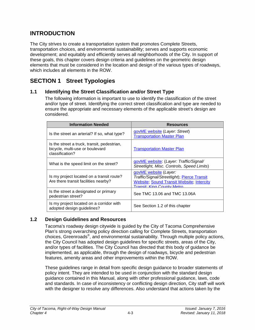
1.1 Identifying the Street Classification and/or Street Type The following information is important to use to identify the classification of the street and/or type of street. Identifying the correct street classification and type are needed to ensure the appropriate and necessary elements of the applicable street’s design are considered.
Information Needed Resources
Is the street an arterial? If so, what type? govME website (Layer: Street) Transportation Master Plan
Is the street a truck, transit, pedestrian, bicycle, multi-use or boulevard classification?
Transportation Master Plan
What is the speed limit on the street? govME website: (Layer: Traffic/Signal/ Streetlight, Misc. Controls, Speed Limits)
Is my project located on a transit route? Are there transit facilities nearby?
govME website (Layer: Traffic/Signal/Streetlight); Pierce Transit Website; Sound Transit Website; Intercity Transit; King County Metro
Is the street a designated or primary pedestrian street? See TMC 13.06 and TMC 13.06A
Is my project located on a corridor with adopted design guidelines? See Section 1.2 of this chapter
1.2 Design Guidelines and Resources Tacoma’s roadway design citywide is guided by the City of Tacoma Comprehensive Plan’s strong overarching policy direction calling for Complete Streets, transportation choices, Greenroads®, and environmental sustainability. Through multiple policy actions, the City Council has adopted design guidelines for specific streets, areas of the City, and/or types of facilities. The City Council has directed that this body of guidance be implemented, as applicable, through the design of roadways, bicycle and pedestrian features, amenity areas and other improvements within the ROW.
These guidelines range in detail from specific design guidance to broader statements of policy intent. They are intended to be used in conjunction with the standard design guidance contained in this Manual, along with other professional guidance, laws, code and standards. In case of inconsistency or conflicting design direction, City staff will work with the designer to resolve any differences. Also understand that actions taken by the
City of Tacoma, Right-of-Way Design Manual Issued: January 7, 2016 Chapter 4 4-3 Revised: January 11, 2018
City Council to amend guiding documents, or to direct the City to implement additional policy or design guidance, must also be considered.
1.2.1 Citywide Design Guidance
• Greenroads® Community Policy and Program: The City became the first "Greenroads® Community" in June 2014 through adoption of Resolution No. 38945. This emphasizes the City’s commitment to develop a policy for the City's roads and other transportation infrastructure in order to be models of environmental, economic, and social stewardship; along with setting community goals for sustainable design, construction, and maintenance. The City is developing a Greenroads® Policy and Program to accomplish the goals established in Resolution No. 38945. The goals outline that all new road construction and full road ROW reconstruction projects excluding alleys, will strive: To achieve Greenroads® certification as financially feasible; To certify an example of each form of road type by Greenroads®. Road
types include arterial, residential, alley, trail, and bridge; and For Greenroads® Gold, or equivalent rating system, certification on all new
road construction and full road ROW reconstruction projects over $5 million.
• Transportation Element of the Comprehensive Plan: The Transportation Element of the Comprehensive Plan (as referred to as the Transportation Master Plan) provides both high level policy and implementation direction on transportation issues throughout the city, pertaining to all travel modes. The plan provides a high level vision of major corridors and backbone networks for all travel modes. It explains what the necessary network improvements are to support the City’s long-range growth strategy. The plan also includes an update on the Mobility Master Plan (MoMaP) which lays out the City’s planned bicycle and pedestrian system. These policies and designations may affect design requirements for projects along the designated routes.
• Pedestrian and Bicycle Guidelines: The Pedestrian and Bicycle Design Guidelines were adopted as a MoMaP implementation strategy and as a part of the Complete Streets Design Guidelines (per Resolution No. 38051). See CHAPTER 10 for additional information on the pedestrian and bicycle guidelines for shared-use paths.
1.2.2 Area-Specific Design Guidelines
• Tacoma Residential Streets Complete Streets Design Guidelines: The City Council has directed that the City implement complete street design guidelines pertaining to Tacoma’s residential streets (per Resolution No. 37916).
• Complete Streets Mixed-Use Centers Design Guidelines: The City Council has directed that the City implement complete street design guidelines pertaining to streets within designated for mixed-use centers areas (per Resolution No. 37916). The appropriate street typology is determined by the design intent and specific conditions of the site/corridor. Types include:
City of Tacoma, Right-of-Way Design Manual Issued: January 7, 2016 Chapter 4 4-4 Revised: January 11, 2018
Mainstreet Avenue Transit priority Urban residential
• Downtown Element of the Comprehensive Plan: The Downtown Element of the Comprehensive Plan outlines a system of street typologies applicable to streets within downtown Tacoma. It designates streets according to the following system of street typologies:
Pedestrian/retail streets Planning for transit priority Connectors Cycling boulevard Urban residential Green streets Yakima Avenue Warehouse district
• Container Port Element of the Comprehensive Plan: This element includes transportation policies regarding the design and operation of transportation infrastructure within the Commencement Bay Tideflats.
• Mixed-Use Centers and Downtown Designated Pedestrian/Primary Pedestrian/Core Pedestrian Streets: This hierarchy is integrated in the zoning code of TMC 13.06 and TMC 13.06A. While it pertains primarily to development standards for private property, it may also influence street design.
• South Downtown, Hilltop, and North Downtown Subarea Plans: These policy documents provide direction for roadway design throughout the Downtown Tacoma Regional Growth Center.
• Downtown Tacoma Streetscape Study and Design Concepts: This design study provides input on street design within downtown Tacoma.
• Sixth Avenue Design Plan, South 38th Street Design Plan, Martin Luther King Jr. Way Design Plans: These policy documents provide relevant policy input for street design in the applicable areas.
• Tacoma Waterfront Design Guidelines: These guidelines provide high level design guidance for projects throughout Tacoma’s shoreline districts.
1.3 Green Stormwater Infrastructure Green Stormwater Infrastructure (GSI) is a set of distributed stormwater BMPs that seek to mimic natural systems and deliver multiple community benefits in addition to stormwater management. GSI can be used at a wide range of landscape scales in place of more traditional stormwater control elements to support the principles of Low Impact Development. GSI has been proven to be a valuable cost effective tool for managing stormwater and meeting the infrastructure needs of the community.
City of Tacoma, Right-of-Way Design Manual Issued: January 7, 2016 Chapter 4 4-5 Revised: January 11, 2018

To assist with implementing GSI an outlined guide has been developed (see Figure 4-1). The first step is to determine if the site discharges stormwater into a fresh or marine watershed. This information can be found on the govME website site under the “Sewer” layer. The second step is to determine the type of road. As described above in Section 1 of this chapter, this information can also be found on the govME website under the “Street” layer. The third step is to consult with Volume 1, Chapter 3 of the SWMM to determine what minimum requirements apply.
Projects that are required to comply with the SWMM, Onsite Stormwater Management Minimum Requirement #5 shall employ the required BMPs and shall follow the order of preference identified in Volume 1, Chapter 3 of the SWMM.
For all other projects see Figure 4-1 to assist in determining the order of preference for choosing the appropriate BMPs to manage stormwater in the City ROW. For select BMPs that are feasible and will meet the associated design criteria, reference the SWMM Volume 3 for Onsite Stormwater Management, Flow Control and Conveyance and Volume 6 for Low Impact Development. It is also recommended to complete an alternatives analysis of the life cycle cost of traditional improvements verses the life cycle cost of a GSI approach.
Figure 4-1: Preferred Green Stormwater Infrastructure Guide
*Shall meet BMPs L630 Bioretention or BMP L633 Permeable Paving Surfaces as appropriate. These are located in Volume 6 of the SWMM.
City of Tacoma, Right-of-Way Design Manual Issued: January 7, 2016 Chapter 4 4-6 Revised: January 11, 2018
SECTION 2 Basis for Geometric Design
Geometric design of roadways shall conform to the guidance and recommendations of American Association of State Highway and Transportation Officials’ A Policy on Geometric Design of Highways and Streets (AASHTO Policy). The AASHTO Policy contains general design parameters for highways and all roads; and specific design parameters for local roads and streets, collectors, arterials, and freeways. Designers shall apply the AASHTO Policy to their specific roadway conditions. It is essential that the designer carefully research the AASHTO Policy to ensure that the recommendations are applicable to the project conditions.
Designers shall also incorporate specific design guidance, as applicable, from the list of resources and documents (collectively to be referred to as the “Street Design Guidelines”) presented in Section 1.2 of this chapter. The vision of the corridor as outlined in the Street Design Guidelines shall be reflected in the geometric design.
Federally classified roadways and roadways on the National Highway System shall meet the design standards required for those roadways. Any modification to those standards shall comply with the deviation process as established by the WSDOT Local Agency Guidelines Manual.
The National Association of City Transportation Officials Urban Street Design Guide has been endorsed by the Federal Highway Administration (FHWA) and the City. It provides an up to date source of urban street design best practices and guidelines and may be used as a design resource for projects within the city.
All streets shall be designed to safely accommodate all modes and users, per the Street Design Guidelines. Multi-modal design features relate to pedestrians, bicycles, mass transportation, high occupancy vehicle traffic, commercial traffic, and general automobile traffic.
2.1 Design Speed The design speed of a facility shall be 5 mph above the 85th Percentile Speed of the prevailing traffic on the subject roadway. On new construction or reconstruction, which significantly alters the characteristics of the roadway, the design speed shall be the posted, designated, or proposed speed limit plus 5 mph. Safety for all users and modes shall be considered when designing multi-modal features, and the design speed shall be both evaluated and applied with the Street Design Guidelines.
The designated speed limit for Tacoma residential streets is 25 mph which corresponds to a 30 mph design speed. Alleys shall be designed using a 20 mph design speed. The designated speed for arterials in Tacoma varies and is on the govME website under the “Street” layer. All streets should be designed for consistent and safe traffic speeds and for the safety of all users and travel modes. The design engineer should contact Traffic Engineering at (253) 573-2332 for determination of the design speed when the project scope of work includes significantly altering the design of a designated arterial.
For non-arterials, in locations where conditions warrant, a reduced design speed may be considered on a case by case basis. Documentation must be provided to Traffic Engineering justifying any and all deviations from the standard design speed.
City of Tacoma, Right-of-Way Design Manual Issued: January 7, 2016 Chapter 4 4-7 Revised: January 11, 2018
2.2 Stopping Sight Distance Stopping sight distance (SSD) is the sum of the distance from when an object is first visible to a vehicle driver to allow for adequate time to apply the brakes to avoid collision plus the distance required to stop the vehicle from the instant brake application begins. These are referred to as reaction distance and braking distance, respectively. The designer shall refer to the AASHTO Policy for SSD design values.
2.3 Design Vehicle Typical residential streets and alleys are to be designed to accommodate a single unit vehicle within the driving lane.
Typical arterial streets, as well as streets in industrial/commercial areas, are to be designed to accommodate a WB-40 (intermediate semi-trailer) design vehicle within the established and striped driving lanes.
The designer shall also investigate if special maneuverability requirements (or a larger design vehicle) are warranted for the specific project location as related to transit routes, emergency response routes, and roadways serving freight traffic or heavy truck operations.
SECTION 3 Geometric Design
3.1 Temporary and Permanent Improvements The City generally classifies a permanent street section as consisting of a standard residential or arterial street section (as defined in Section 5 of this chapter) with associated full width and alignment. Permanent streets typically include sidewalk(s) in combination with concrete curbs. The design of GSI and Low Impact Development features will govern design features other than concrete curb at the edge of pavement. The design of the permanent improvements may mandate providing some temporary improvements to accommodate tapers, access, drainage, etc. to the approval of the City Engineer.
Temporary improvements are those street improvements that are to be constructed in a non-standard temporary alignment. This may be allowed where a new side street or alley is connected to a street that is in a temporary state and the temporary construction falls outside project limits or required frontage improvement limits. Temporary street improvements may utilize asphalt wedge curb instead of concrete curb. The minimum pavement section for temporary improvements shall not be less than 2 inches hot mix asphalt (HMA) over 2 inches crushed surfacing top course (CSTC). Providing dust and erosion control measures to improve air and water quality, and safety enhancements are some of the primary objectives for providing temporary improvements.
Both permanent and temporary improvements shall conform to the geometric guidelines outlined below in Section 3.2, as applicable.
3.2 Geometric Guidelines In order of decreasing hierarchy, the designer shall comply with the following directives:
City of Tacoma, Right-of-Way Design Manual Issued: January 7, 2016 Chapter 4 4-8 Revised: January 11, 2018
1. The geometric design of the improvements shall conform to this chapter and the design shall align with the alignment and elevation of any existing adjacent permanent improvements.
2. The geometric design of the improvements shall conform to this chapter and the design shall take into consideration any future improvements identified by the City Engineer which would tie into existing permanent improvements in the vicinity.
3. The geometric design of the improvements shall conform to this chapter and the design shall provide a best fit design which will adequately channelize traffic and connect to any existing temporary improvements.
Under no circumstances shall temporary street sections dictate the design of the permanent street improvements. A safe, smooth transition must be provided to any temporary improvements. Additional pavement removal and replacement may be required to provide an adequate transition or crown to the street. In some cases removal and replacement of the street may extend to the centerline or beyond the centerline (see the City of Tacoma’s Right-of-Way Restoration Policy). Temporary street improvements shall meet all requirements of and provide mitigation per the SWMM.
3.3 Straight Grades
3.3.1 Longitudinal Grade Asphalt cannot be placed at a grade less than 1 percent and maintain positive drainage. Therefore, where asphalt wedge curbs will be constructed, a 1 percent minimum longitudinal grade shall be provided or some mechanism for temporary grade control shall be addressed in the design. Due to the difference in minimum grades between temporary asphalt wedge curb and the construction of permanent curb and gutter, the grades required in order to construct the temporary asphalt wedge curb may substantially control the design of a half street.
When concrete curb and gutter is being installed the minimum longitudinal grade may be reduced to no less than 0.3 percent.
Permeable roadways shall maintain a 0.5 percent minimum longitudinal grade. Gutters are strongly discouraged for permeable roadways and will be considered only on a case by case basis. If gutters are approved, overflow infiltration galleries will be required to navigate gutter drainage into the reservoir course.
Roadways with alternative drainage systems such as bioretention or swales may not require a longitudinal grade.
3.3.2 Maximum Grade The design engineer should refer to the AASHTO Policy for maximum grades for all road classifications as applicable to each specific road design project. Additionally, in commercial and industrial areas, grades shall not exceed 8 percent and any proposed grades in excess of 5 percent will require approval from the City. Permeable pavements shall not exceed 10 percent. Improvements to existing roads and streets, and new roads that are severely constrained by existing topography (greater than 8 percent slopes) shall be designed to have the lowest feasible grades, and shall be reviewed on a case-by-case basis.
City of Tacoma, Right-of-Way Design Manual Issued: January 7, 2016 Chapter 4 4-9 Revised: January 11, 2018
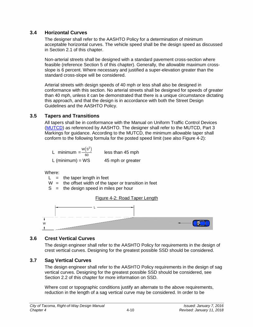
3.4 Horizontal Curves The designer shall refer to the AASHTO Policy for a determination of minimum acceptable horizontal curves. The vehicle speed shall be the design speed as discussed in Section 2.1 of this chapter.
Non-arterial streets shall be designed with a standard pavement cross-section where feasible (reference Section 5 of this chapter). Generally, the allowable maximum cross-slope is 6 percent. Where necessary and justified a super-elevation greater than the standard cross-slope will be considered.
Arterial streets with design speeds of 40 mph or less shall also be designed in conformance with this section. No arterial streets shall be designed for speeds of greater than 40 mph, unless it can be demonstrated that there is a unique circumstance dictating this approach, and that the design is in accordance with both the Street Design Guidelines and the AASHTO Policy.
3.5 Tapers and Transitions All tapers shall be in conformance with the Manual on Uniform Traffic Control Devices (MUTCD) as referenced by AASHTO. The designer shall refer to the MUTCD, Part 3 Markings for guidance. According to the MUTCD, the minimum allowable taper shall conform to the following formula for the posted speed limit (see also Figure 4-2):
L (minimum)=W�S2�
60 less than 45 mph
L (minimum) = WS 45 mph or greater
Where: L = the taper length in feet W = the offset width of the taper or transition in feet S = the design speed in miles per hour
Figure 4-2: Road Taper Length
3.6 Crest Vertical Curves The design engineer shall refer to the AASHTO Policy for requirements in the design of crest vertical curves. Designing for the greatest possible SSD should be considered.
3.7 Sag Vertical Curves The design engineer shall refer to the AASHTO Policy requirements in the design of sag vertical curves. Designing for the greatest possible SSD should be considered, see Section 2.2 of this chapter for more information on SSD.
Where cost or topographic conditions justify an alternate to the above requirements, reduction in the length of a sag vertical curve may be considered. In order to be
City of Tacoma, Right-of-Way Design Manual Issued: January 7, 2016 Chapter 4 4-10 Revised: January 11, 2018
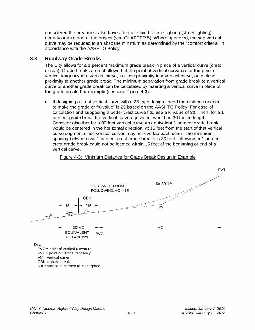
considered the area must also have adequate fixed source lighting (street lighting) already or as a part of the project (see CHAPTER 5). Where approved, the sag vertical curve may be reduced to an absolute minimum as determined by the “comfort criteria” in accordance with the AASHTO Policy.
3.8 Roadway Grade Breaks The City allows for a 1 percent maximum grade break in place of a vertical curve (crest or sag). Grade breaks are not allowed at the point of vertical curvature or the point of vertical tangency of a vertical curve, in close proximity to a vertical curve, or in close proximity to another grade break. The minimum separation from grade break to a vertical curve or another grade break can be calculated by inserting a vertical curve in place of the grade break. For example (see also Figure 4-3):
• If designing a crest vertical curve with a 35 mph design speed the distance needed to make the grade or “K-value” is 29 based on the AASHTO Policy. For ease of calculation and supposing a better crest curve fits, use a K-value of 30. Then, for a 1 percent grade break the vertical curve equivalent would be 30 feet in length. Consider also that for a 30 foot vertical curve an equivalent 1 percent grade break would be centered in the horizontal direction, at 15 feet from the start of that vertical curve segment since vertical curves may not overlap each other. The minimum spacing between two 1 percent crest grade breaks is 30 feet. Likewise, a 1 percent crest grade break could not be located within 15 feet of the beginning or end of a vertical curve.
Figure 4-3: Minimum Distance for Grade Break Design in Example
Key:
PVC = point of vertical curvature PVT = point of vertical tangency VC = vertical curve GBK = grade break K = distance to needed to meet grade
City of Tacoma, Right-of-Way Design Manual Issued: January 7, 2016 Chapter 4 4-11 Revised: January 11, 2018
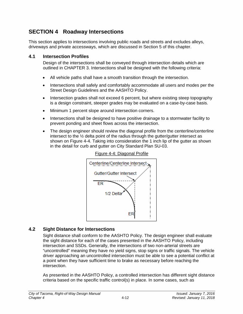
SECTION 4 Roadway Intersections
This section applies to intersections involving public roads and streets and excludes alleys, driveways and private accessways, which are discussed in Section 5 of this chapter.
4.1 Intersection Profiles Design of the intersections shall be conveyed through intersection details which are outlined in CHAPTER 3. Intersections shall be designed with the following criteria:
• All vehicle paths shall have a smooth transition through the intersection.
• Intersections shall safely and comfortably accommodate all users and modes per the Street Design Guidelines and the AASHTO Policy.
• Intersection grades shall not exceed 6 percent, but where existing steep topography is a design constraint, steeper grades may be evaluated on a case-by-case basis.
• Minimum 1 percent slope around intersection corners.
• Intersections shall be designed to have positive drainage to a stormwater facility to prevent ponding and sheet flows across the intersection.
• The design engineer should review the diagonal profile from the centerline/centerline intersect to the ½ delta point of the radius through the gutter/gutter intersect as shown on Figure 4-4. Taking into consideration the 1 inch lip of the gutter as shown in the detail for curb and gutter on City Standard Plan SU-03.
Figure 4-4: Diagonal Profile
4.2 Sight Distance for Intersections Sight distance shall conform to the AASHTO Policy. The design engineer shall evaluate the sight distance for each of the cases presented in the AASHTO Policy, including intersection and SSDs. Generally, the intersections of two non-arterial streets are “uncontrolled” meaning they have no yield signs, stop signs or traffic signals. The vehicle driver approaching an uncontrolled intersection must be able to see a potential conflict at a point when they have sufficient time to brake as necessary before reaching the intersection.
As presented in the AASHTO Policy, a controlled intersection has different sight distance criteria based on the specific traffic control(s) in place. In some cases, such as
City of Tacoma, Right-of-Way Design Manual Issued: January 7, 2016 Chapter 4 4-12 Revised: January 11, 2018
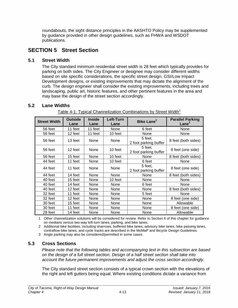
roundabouts, the sight distance principles in the AASHTO Policy may be supplemented by guidance provided in other design guidelines, such as FHWA and WSDOT publications.
SECTION 5 Street Section
5.1 Street Width The City standard minimum residential street width is 28 feet which typically provides for parking on both sides. The City Engineer or designee may consider different widths based on site specific considerations, the specific street design, GSI/Low Impact Development designs, or existing improvements that may dictate the alignment of the curb. The design engineer shall consider the existing improvements, including trees and landscaping, public art, historic features, and other pertinent features in the area and may base the design of the street section accordingly.
5.2 Lane Widths Table 4-1: Typical Channelization Combinations by Street Width1
Street Width Outside Lane
Inside Lane
Left-Turn Lane Bike Lane2 Parallel Parking
Lane3
56 feet 11 feet 11 feet None 6 feet None 56 feet 12 feet 11 feet 10 feet None None
56 feet 13 feet None None 5 feet, 2 foot parking buffer 8 feet (both sides)
56 feet 12 feet None 10 feet 5 feet, 2 foot parking buffer 8 feet (one side)
56 feet 15 feet None 10 feet None 8 feet (both sides) 44 feet 11 feet None 10 feet 6 feet None
44 feet 11 feet None None 5 feet, 2 foot parking buffer 8 feet (one side)
44 feet 14 feet None None None 8 feet (both sides) 40 feet 15 feet None 10 feet None None 40 feet 14 feet None None 6 feet None 40 feet 12 feet None None None 8 feet (both sides) 32 feet 11 feet None None 5 feet None 32 feet 12 feet None None None 8 feet (one side) 30 feet 15 feet None None None Allowable 30 feet 11 feet None None None 8 feet (one side) 28 feet 14 feet None None None Allowable
1 Other channelization solutions will be considered for review. Refer to Section 6 of this chapter for guidance on medians versus two-way left-turn lanes, parking, and bike lanes.
2 Additional bike facilities, including sharrows, buffered bike lanes, advisory bike lanes, bike passing lanes, contraflow bike lanes, and cycle tracks are described in the MoMaP and Bicycle Design Guidelines.
3 Angle parking may also be considered/permitted in some cases.
5.3 Cross Sections Please note that the following tables and accompanying text in this subsection are based on the design of a full street section. Design of a half street section shall take into account the future permanent improvements and adjust the cross section accordingly.
The City standard street section consists of a typical crown section with the elevations of the right and left gutters being equal. Where existing conditions dictate a variance from
City of Tacoma, Right-of-Way Design Manual Issued: January 7, 2016 Chapter 4 4-13 Revised: January 11, 2018
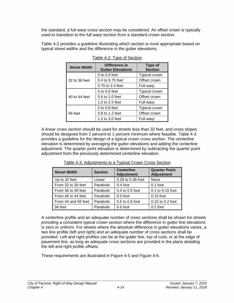
the standard, a full warp cross section may be considered. An offset crown is typically used to transition to the full warp section from a standard crown section.
Table 4-2 provides a guideline illustrating which section is most appropriate based on typical street widths and the difference in the gutter elevations.
Table 4-2: Type of Section
Street Width Difference in Gutter Elevations
Type of Section
32 to 36 feet 0 to 0.4 feet Typical crown 0.4 to 0.75 feet Offset crown 0.75 to 2.0 feet Full warp
40 to 44 feet 0 to 0.6 feet Typical crown 0.6 to 1.0 feet Offset crown 1.0 to 2.5 feet Full warp
56 feet 0 to 0.8 feet Typical crown 0.8 to 1.2 feet Offset crown 1.2 to 3.0 feet Full warp
A linear cross section should be used for streets less than 32 feet, and cross slopes should be designed from 2 percent to 1 percent minimum where feasible. Table 4-3 provides a guideline for the design of a typical crown cross section. The centerline elevation is determined by averaging the gutter elevations and adding the centerline adjustment. The quarter point elevation is determined by subtracting the quarter point adjustment from the previously determined centerline elevation.
Table 4-3: Adjustments to a Typical Crown Cross Section
Street Width Section Centerline Adjustment
Quarter Point Adjustment
Up to 32 feet Linear 0.28 to 0.36 foot None From 32 to 36 feet Parabolic 0.4 foot 0.1 foot From 36 to 40 feet Parabolic 0.4 to 0.5 foot 0.1 to 0.15 foot From 40 to 44 feet Parabolic 0.5 foot 0.15 foot From 44 and 56 feet Parabolic 0.5 to 0.6 foot 0.15 to 0.2 foot 56 feet Parabolic 0.6 foot 0.2 foot
A centerline profile and an adequate number of cross sections shall be shown for streets providing a consistent typical crown section where the difference in gutter line elevations is zero or uniform. For streets where the absolute difference in gutter elevations varies, a two line profile (left and right) and an adequate number of cross sections shall be provided. Left and right profiles can be at the gutter line, top of curb, or at the edge of pavement line, as long as adequate cross sections are provided in the plans detailing the left and right profile offsets.
These requirements are illustrated in Figure 4-5 and Figure 4-6.
City of Tacoma, Right-of-Way Design Manual Issued: January 7, 2016 Chapter 4 4-14 Revised: January 11, 2018
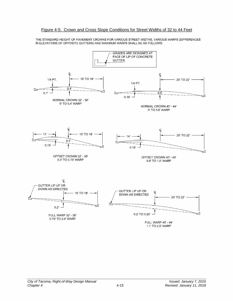
Figure 4-5: Crown and Cross Slope Conditions for Street Widths of 32 to 44 Feet
City of Tacoma, Right-of-Way Design Manual Issued: January 7, 2016 Chapter 4 4-15 Revised: January 11, 2018
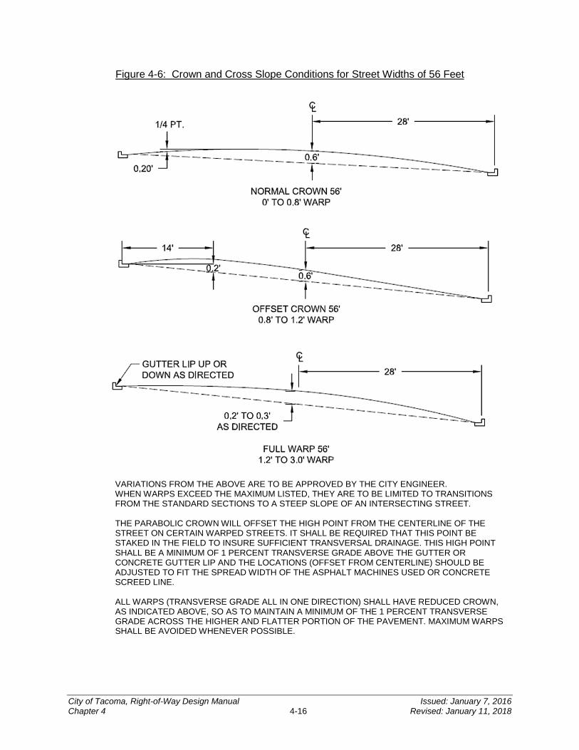
Figure 4-6: Crown and Cross Slope Conditions for Street Widths of 56 Feet
VARIATIONS FROM THE ABOVE ARE TO BE APPROVED BY THE CITY ENGINEER. WHEN WARPS EXCEED THE MAXIMUM LISTED, THEY ARE TO BE LIMITED TO TRANSITIONS FROM THE STANDARD SECTIONS TO A STEEP SLOPE OF AN INTERSECTING STREET. THE PARABOLIC CROWN WILL OFFSET THE HIGH POINT FROM THE CENTERLINE OF THE STREET ON CERTAIN WARPED STREETS. IT SHALL BE REQUIRED THAT THIS POINT BE STAKED IN THE FIELD TO INSURE SUFFICIENT TRANSVERSAL DRAINAGE. THIS HIGH POINT SHALL BE A MINIMUM OF 1 PERCENT TRANSVERSE GRADE ABOVE THE GUTTER OR CONCRETE GUTTER LIP AND THE LOCATIONS (OFFSET FROM CENTERLINE) SHOULD BE ADJUSTED TO FIT THE SPREAD WIDTH OF THE ASPHALT MACHINES USED OR CONCRETE SCREED LINE. ALL WARPS (TRANSVERSE GRADE ALL IN ONE DIRECTION) SHALL HAVE REDUCED CROWN, AS INDICATED ABOVE, SO AS TO MAINTAIN A MINIMUM OF THE 1 PERCENT TRANSVERSE GRADE ACROSS THE HIGHER AND FLATTER PORTION OF THE PAVEMENT. MAXIMUM WARPS SHALL BE AVOIDED WHENEVER POSSIBLE.
City of Tacoma, Right-of-Way Design Manual Issued: January 7, 2016 Chapter 4 4-16 Revised: January 11, 2018
5.4 Subgrade Preparation The above standard sections are designed to be placed upon a firm and unyielding subgrade according to WSDOT Standard Specifications, Section 2-06. Verifying the condition of the subgrade by “proof rolling” is required.
5.4.1 Permeable Pavement Subgrade Subgrade shall be limited to 3 percent slope. If the roadway surface grade exceeds 3 percent, terraces shall be included per the standard plan. Check dams are discouraged and will only be approved on a case by case basis. The top of check dams shall be a minimum of 3 inches below the wearing course.
A minimum of 1 foot of vertical separation is required between the bottom of the lowest gravel base course and the seasonal high groundwater elevation or other impermeable layer to ensure that a saturated condition is not created.
For permeable pavements, the exposed subgrade shall maintain preconstruction infiltration rates. The subgrade shall be protected from siltation or over-compaction, including replacing all material that becomes unsuitable while the subgrade is exposed.
Traffic should be limited to emergency access during construction. If traffic is allowed on the exposed subgrade, the subgrade shall be re-evaluated for infiltration and scarification may be required. The subgrade must be suitable, as determined by the design engineer, prior to placement of geotextile fabric (if required) or permeable ballast base course.
To prevent excessive subgrade compaction the following procedure shall be adhered to:
1. Excavation to final subgrade elevation shall occur immediately prior to placing pavement section materials and paving. If necessary, the contractor may excavate to an intermediate subgrade elevation established at 12 inches above the final subgrade elevation.
2. Grading to final subgrade elevation shall be completed by machinery operating on the intermediate subgrade level or the adjacent non-pervious pavement subgrade.
3. To prevent excessive compaction of subgrade during placement of pavement section material follow these steps:
a. Excavate to subgrade elevation using method by which equipment, including trucks, are not operated on the final subgrade elevation.
b. Scarify the top 4 inches of subgrade to a firm and unyielding condition.
c. Compact subgrade to density specified by the design engineer.
d. Install geotextile fabric (if required).
City of Tacoma, Right-of-Way Design Manual Issued: January 7, 2016 Chapter 4 4-17 Revised: January 11, 2018
e. Back dump the material onto the subgrade from the edge of the installation and push it out onto the subgrade using low ground pressure equipment. Trucks then back dump subsequent loads on top of the previously dumped/pushed material as the installation progresses.
4. Avoid subgrade preparation during wet conditions.
Contractor shall phase the work in order to not compromise or excessively compact the subgrade. Should it be necessary for machinery or trucks to access the final subgrade in certain areas, the contractor shall protect those areas from over-compaction by placing steel sheets to diffuse point loading.
Infiltration tests shall be completed immediately following final subgrade preparation to verify that the subgrade is not over-compacted. The test shall be conducted using the small scale Pilot Infiltration Test as outlined in Volume 3 of the SWMM. Projects required to install permeable pavements per the Minimum Requirements of the SWMM shall follow acceptance requirements of the SWMM.
Infiltration tests shall be conducted at a rate of 1 test per 5000 square feet, or 1 test per 200 lineal feet of residential roadway, or one test per lot for residential sites. Infiltration tests of the subgrade shall be conducted at the discretion of the design engineer.
Areas determined to be overly compacted, in the sole opinion of the design engineer, shall be scarified by the contractor to a depth specified by the design engineer and re-compacted.
5.5 Pavement Section Pavement section standards, including minimum design values, are provided in Standard Plans PD-01 and PD-02. The base material for all sections shall extend 1 foot beyond the back of the concrete curb or asphalt wedge curb.
Alternate sections providing the same structural number may be proposed, and are subject to approval by the City. The designer may design the alternate pavement section using the process outlined in the AASHTO Guide for Design of Pavement Structures. Emerging new design methods may be considered for review and compared with the AASHTO Guide for Design of Pavement Structures design results, taking into consideration the average daily truck traffic, and the existing soil conditions.
The minimum design life for asphalt pavements shall be 20 years, and the minimum design life for a concrete pavement section shall be 40 years. However, the designer should evaluate the life cycle costs of a 40 year asphalt design life. Additionally, the standard section may need to be increased upon further review, depending on soil conditions, such as in the port area. The City may require a geotechnical analysis for review.
Alternate sections, including permeable pavements, will require a geotechnical analysis and pavement calculations as described above. For alternate or permeable pavement sections, geotechnical analysis and recommendations will be required, that will support the proposed permeable ballast base course thickness. The thickness will be determined
City of Tacoma, Right-of-Way Design Manual Issued: January 7, 2016 Chapter 4 4-18 Revised: January 11, 2018
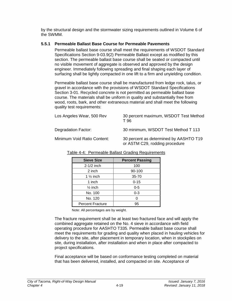
by the structural design and the stormwater sizing requirements outlined in Volume 6 of the SWMM.
5.5.1 Permeable Ballast Base Course for Permeable Pavements Permeable ballast base course shall meet the requirements of WSDOT Standard Specifications Section 9-03.9(2) Permeable Ballast except as modified by this section. The permeable ballast base course shall be seated or compacted until no visible movement of aggregate is observed and approved by the design engineer. Immediately following spreading and final shaping each layer of surfacing shall be lightly compacted in one lift to a firm and unyielding condition.
Permeable ballast base course shall be manufactured from ledge rock, talus, or gravel in accordance with the provisions of WSDOT Standard Specifications Section 3-01. Recycled concrete is not permitted as permeable ballast base course. The materials shall be uniform in quality and substantially free from wood, roots, bark, and other extraneous material and shall meet the following quality test requirements:
Los Angeles Wear, 500 Rev 30 percent maximum, WSDOT Test Method T 96
Degradation Factor: 30 minimum, WSDOT Test Method T 113
Minimum Void Ratio Content: 30 percent as determined by AASHTO T19 or ASTM C29, rodding procedure
Table 4-4: Permeable Ballast Grading Requirements
Sieve Size Percent Passing 2-1/2 inch 100
2 inch 90-100 1 ½ inch 35-70
1 inch 0-15 ½ inch 0-5 No. 100 0-3 No. 120 0
Percent Fracture 95 Note: All percentages are by weight.
The fracture requirement shall be at least two fractured face and will apply the combined aggregate retained on the No. 4 sieve in accordance with field operating procedure for AASHTO T335. Permeable ballast base course shall meet the requirements for grading and quality when placed in hauling vehicles for delivery to the site, after placement in temporary location, when in stockpiles on site, during installation, after installation and when in place after compacted to project specifications.
Final acceptance will be based on conformance testing completed on material that has been delivered, installed, and compacted on site. Acceptance of
City of Tacoma, Right-of-Way Design Manual Issued: January 7, 2016 Chapter 4 4-19 Revised: January 11, 2018
permeable ballast base course shall be as provided under nonstatistical or commercial evaluations.
5.6 Curbs Standard cement concrete curb and gutter shall be constructed per City Standard Plan SU-03, unless otherwise approved by the City Engineer or designee. Curb and gutter with combination sidewalk must be provided for at least 25 feet at bus stops to form a landing to service the front and rear doors of a city bus. The City will coordinate with the applicant to contact Pierce Transit’s Transit Development Group.
Other curb types shown on City Standard Plan SU-03 may be used in specific instances and will be approved on a case-by-case basis as part of the City review and approval process.
In some cases, where full warp street sections are approved the City will require gutters to be designed lip down, meaning where the gutter does not trap water. Lipped down gutters may also be required in the design of intersections, on street parking stalls, bus turnouts, etc. Lip-down gutters can be at running grades less than 0.3 percent, if only the rest of the street will be graded to drain according to Section 2 of this chapter.
Alternative curb or gutter-less road edging may be appropriate for GSI designs. Permeable roadways should be designed with cement concrete traffic curb. See Section 5.3 of this chapter for more information.
Where there are existing granite curbs and/or brick gutters, consideration shall be made for retaining the historic configuration or salvaging the materials based on approval by the City’s Historic Preservation Office (253) 591-5577. The City shall retain possession of such materials if they are removed.
All curb and gutter shall flow into the stormwater system which might include a catch basin, curb cut, or other facility. Additional catch basins or extension of the curb and gutter or wedge curb may be required to ensure stormwater is conveyed appropriately.
5.7 Asphalt Wedge Curb In areas where curb and gutter is not required, all new asphalt pavement shall include an asphalt wedge curb unless stormwater sheet flows into a stormwater facility. An asphalt wedge curb consists of a 3 inch high by 12 inch wide thickened edge of asphalt. Where a full warp of the street is approved and the proposed asphalt wedge curb is on the downhill side of the warp, a 6 inch by 18 inch asphalt wedge curb shall be used. If there is a bus stop in an area with asphalt wedge only, additional asphalt behind the wedge curb should be included in order to provide a suitable boarding area. Applicant shall coordinate with the City to contact Pierce Transit’s Transit Development Group.
Typically, the top of the asphalt wedge curb does not provide for a reliable vertical control point; therefore, the grade point of an asphalt wedge curb shall be the flowline as referenced by the City Standard Plan SU-26. The back of the wedge curb shall denote the alignment.
All wedge curb shall flow into the stormwater system which might include a catch basin, curb cut, or other facility. Additional catch basins or extension of the wedge curb may be required to ensure stormwater is conveyed appropriately.
City of Tacoma, Right-of-Way Design Manual Issued: January 7, 2016 Chapter 4 4-20 Revised: January 11, 2018
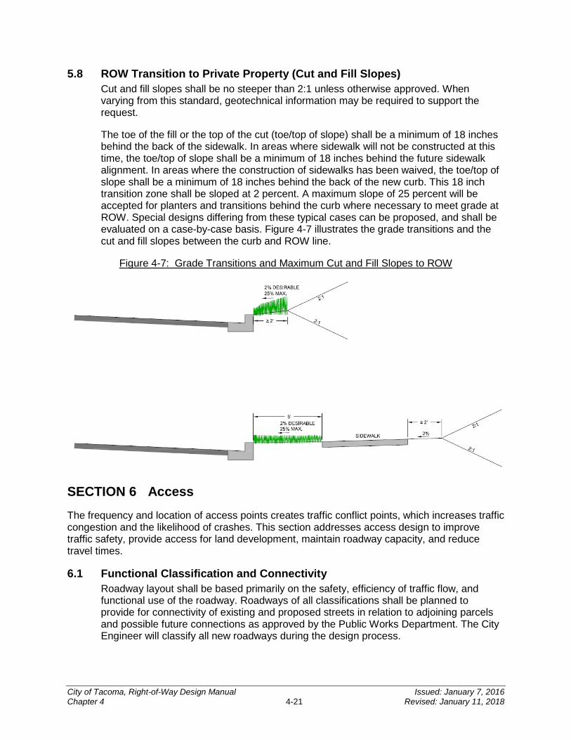
5.8 ROW Transition to Private Property (Cut and Fill Slopes) Cut and fill slopes shall be no steeper than 2:1 unless otherwise approved. When varying from this standard, geotechnical information may be required to support the request.
The toe of the fill or the top of the cut (toe/top of slope) shall be a minimum of 18 inches behind the back of the sidewalk. In areas where sidewalk will not be constructed at this time, the toe/top of slope shall be a minimum of 18 inches behind the future sidewalk alignment. In areas where the construction of sidewalks has been waived, the toe/top of slope shall be a minimum of 18 inches behind the back of the new curb. This 18 inch transition zone shall be sloped at 2 percent. A maximum slope of 25 percent will be accepted for planters and transitions behind the curb where necessary to meet grade at ROW. Special designs differing from these typical cases can be proposed, and shall be evaluated on a case-by-case basis. Figure 4-7 illustrates the grade transitions and the cut and fill slopes between the curb and ROW line.
Figure 4-7: Grade Transitions and Maximum Cut and Fill Slopes to ROW
SECTION 6 Access The frequency and location of access points creates traffic conflict points, which increases traffic congestion and the likelihood of crashes. This section addresses access design to improve traffic safety, provide access for land development, maintain roadway capacity, and reduce travel times.
6.1 Functional Classification and Connectivity Roadway layout shall be based primarily on the safety, efficiency of traffic flow, and functional use of the roadway. Roadways of all classifications shall be planned to provide for connectivity of existing and proposed streets in relation to adjoining parcels and possible future connections as approved by the Public Works Department. The City Engineer will classify all new roadways during the design process.
City of Tacoma, Right-of-Way Design Manual Issued: January 7, 2016 Chapter 4 4-21 Revised: January 11, 2018

Arterial roadways are intended for the efficient movement of people and goods, and have the highest level of access control. Collector arterials generally connect commercial, industrial, and residential projects to other collectors. These roadways have a moderate level of access control. Residential streets shall interconnect with each other and with collectors and have a minimum level of access control. Roadway classifications can be found in the Transportation Master Plan and TMC 11.05. Courts and alleys are intended to provide local access; with encouraged use of alleys in residential neighborhoods.
New developments shall provide new roadways and connections which support interconnectivity including pedestrian accessibility to bus stops and non-motorized routes. Grid connections, connections to adjacent parcels, shared access, and new roadways shown in the Transportation Master Plan are examples of ways the City requires interconnectivity of the roadway network. Connections between similarly zoned properties shall be provided. Internal accessways shall provide stubs to adjacent parcels and reciprocal access agreements. Roadway connections shall be extended to and through property lines.
6.2 Access Management Access management focuses on the location, spacing, and design of entrances, street intersections, and alleys. Each access location creates conflict points where vehicles interact with other vehicles or pedestrians causing delay and potential safety concerns.
State facilities operated within the City shall meet these access standards in addition to the access management state regulations in Revised Code of Washington (RCW) 47.50, Washington Administrative Code (WAC) 468-51, and WAC 468-52.
Determination of permitted access, including number, location, and size, shall be the responsibility of the City. The following information will be used to evaluate access and should be consulted prior to street design:
1. The Citywide Design Guidance Documents (Section 1.2.1 of this chapter) and Area-Specific Design Guidelines (Section 1.2.2 of this chapter), zoning, and land development regulations as set forth in adopted City comprehensive plans.
2. The current functional classification of the roadway (or potential classification in the case of a new roadway).
3. Existing and projected traffic volumes, crash history, non-motorized volumes, and other operational considerations.
4. Existing and projected state, local, and regional planning organization transportation plans and needs, including considerations of new or improved facilities.
5. Drainage requirements and utilities.
6. The physical features of land adjoining the roadway.
7. The type and volume of traffic requiring access.
8. The availability of alternative or shared connections to the existing roadway network.
9. The cumulative effect of existing and projected connections on the roadway’s ability to provide safe and efficient movement of people and goods.
City of Tacoma, Right-of-Way Design Manual Issued: January 7, 2016 Chapter 4 4-22 Revised: January 11, 2018
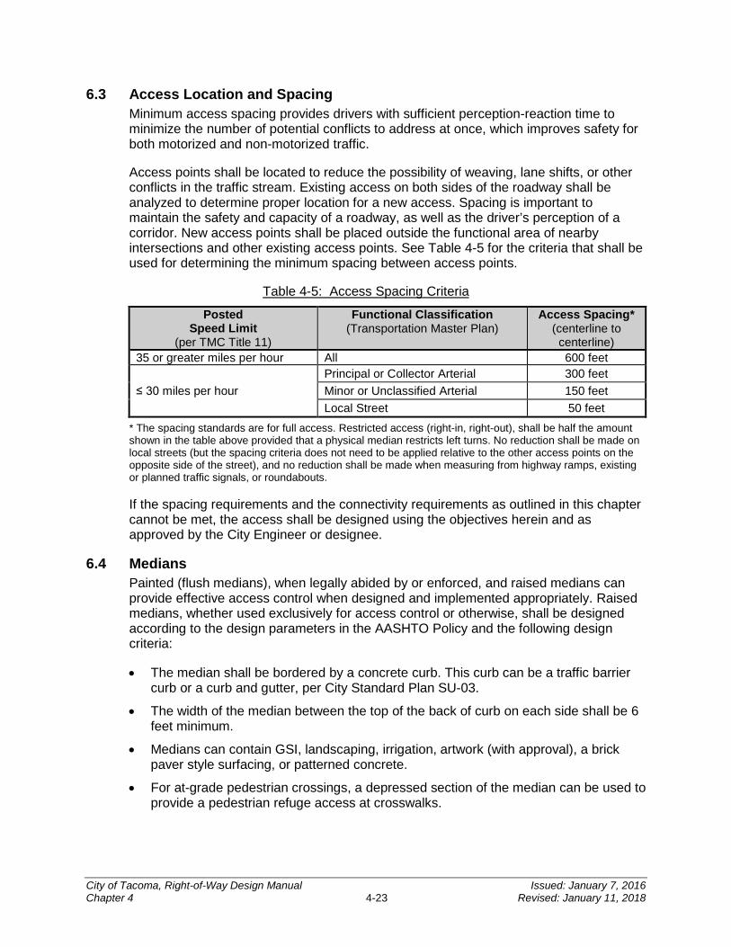
6.3 Access Location and Spacing Minimum access spacing provides drivers with sufficient perception-reaction time to minimize the number of potential conflicts to address at once, which improves safety for both motorized and non-motorized traffic.
Access points shall be located to reduce the possibility of weaving, lane shifts, or other conflicts in the traffic stream. Existing access on both sides of the roadway shall be analyzed to determine proper location for a new access. Spacing is important to maintain the safety and capacity of a roadway, as well as the driver’s perception of a corridor. New access points shall be placed outside the functional area of nearby intersections and other existing access points. See Table 4-5 for the criteria that shall be used for determining the minimum spacing between access points.
Table 4-5: Access Spacing Criteria
Posted Speed Limit
(per TMC Title 11)
Functional Classification (Transportation Master Plan)
Access Spacing* (centerline to centerline)
35 or greater miles per hour All 600 feet
≤ 30 miles per hour Principal or Collector Arterial 300 feet Minor or Unclassified Arterial 150 feet Local Street 50 feet
* The spacing standards are for full access. Restricted access (right-in, right-out), shall be half the amount shown in the table above provided that a physical median restricts left turns. No reduction shall be made on local streets (but the spacing criteria does not need to be applied relative to the other access points on the opposite side of the street), and no reduction shall be made when measuring from highway ramps, existing or planned traffic signals, or roundabouts.
If the spacing requirements and the connectivity requirements as outlined in this chapter cannot be met, the access shall be designed using the objectives herein and as approved by the City Engineer or designee.
6.4 Medians Painted (flush medians), when legally abided by or enforced, and raised medians can provide effective access control when designed and implemented appropriately. Raised medians, whether used exclusively for access control or otherwise, shall be designed according to the design parameters in the AASHTO Policy and the following design criteria:
• The median shall be bordered by a concrete curb. This curb can be a traffic barrier curb or a curb and gutter, per City Standard Plan SU-03.
• The width of the median between the top of the back of curb on each side shall be 6 feet minimum.
• Medians can contain GSI, landscaping, irrigation, artwork (with approval), a brick paver style surfacing, or patterned concrete.
• For at-grade pedestrian crossings, a depressed section of the median can be used to provide a pedestrian refuge access at crosswalks.
City of Tacoma, Right-of-Way Design Manual Issued: January 7, 2016 Chapter 4 4-23 Revised: January 11, 2018

• The Citywide Design Guidance Documents (Section 1.2.1) and Area-Specific Design Guidelines (Section 1.2.2) shall be applied to determine design aspects and/or amenities appropriate for the specific project area.
• Access/parking for authorized vehicles only shall be considered and provided as necessary for medians that contain items that require maintenance.
6.5 Driveways All driveways shall be in conformance with the TMC 10.14, TMC 13.06, and the City Standard Plans. In cases where driveway provisions applicable to a particular application exist in either referenced TMC section, or other section of the TMC, all standards shall apply, with the more stringent provisions prevailing in the case of a conflict created by application of separate standards. Exceptions may be allowed by the City Engineer for public safety or if strict application of these standards would prohibit vehicular access to a development, pursuant to TMC 10.14.
New driveways are subject to review and approval by the City Engineer pursuant to TMC 10.14, taking into account safe traffic flow, existing and planned transit operations, the objectives and requirements of this chapter, and the efficient functionality of the development. New driveways can be prohibited or their associated traffic movements restricted on designated pedestrian streets (see TMC 13.06 and 13.06A for the list of applicable streets).
New driveways shall be located from an alley or court when suitable access is available, such as an abutting ROW that is or can practicably be developed.
City Standard Plan SU-07 and SU-08 show driveways used for residential and commercial access and at the entrance to private accessways. Driveways shall be designed to meet applicable ADA and Public Rights-of-Way Guidelines (PROWAG) standards, and applicable design guidelines of the City.
Type 1 and Type 2 concrete driveways are to be constructed where concrete curb and gutter is proposed or existing. Temporary asphalt driveways should be constructed elsewhere. Please note that for historic districts, special design standards may apply.
The City may require an increased driveway thickness or steel reinforcement in addition to the pavement requirements discussed in Section 5.5 for locations in the Commencement Bay Tideflats or where poor soil conditions exist.
6.6 Private Accessways A private accessway serving four lots or fewer may be designed as outlined in this section. Private streets serving five or more lots shall be designed to City standards as outlined in this chapter and in CHAPTER 2. Private streets will not be allowed if there is the ability for a future roadway extension or pedestrian access route (PAR).
It is incumbent upon the design engineer to provide safe adequate access for all lots. The City strongly recommends that the design engineer follow the recommendations from the AASHTO Policy as discussed in this chapter.
All private streets and accessways shall:
1. Address adverse impacts to adjacent private property;
City of Tacoma, Right-of-Way Design Manual Issued: January 7, 2016 Chapter 4 4-24 Revised: January 11, 2018
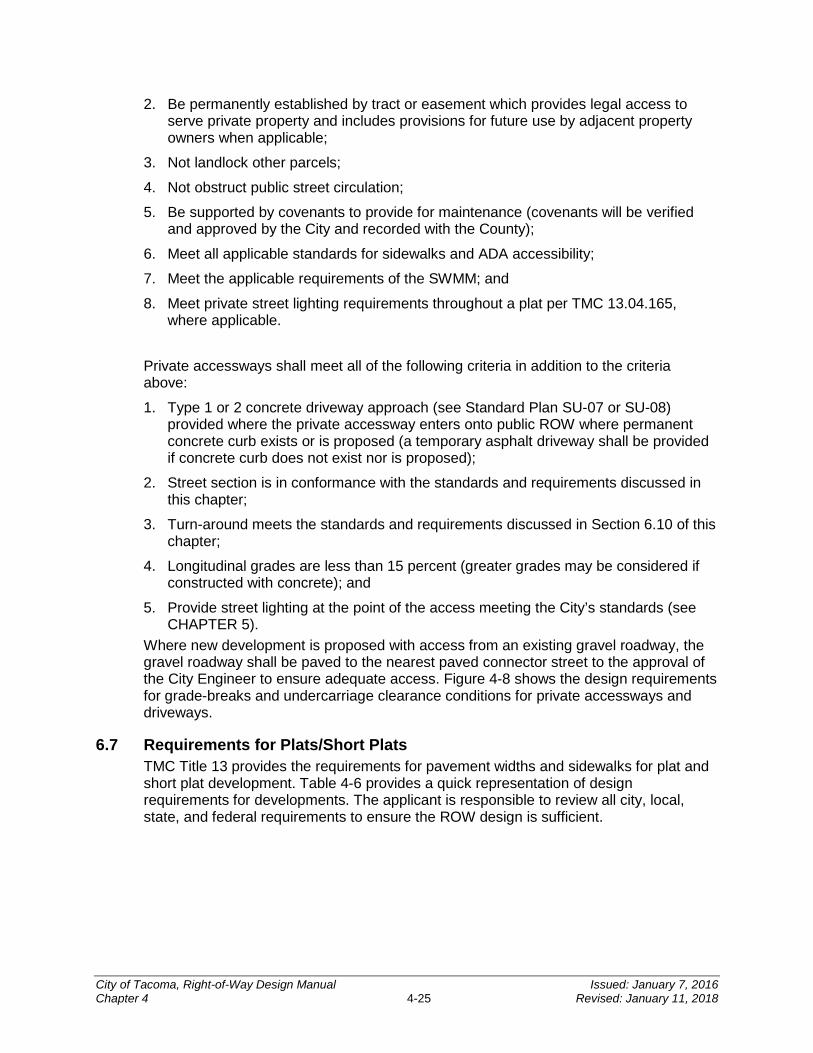
2. Be permanently established by tract or easement which provides legal access to serve private property and includes provisions for future use by adjacent property owners when applicable;
3. Not landlock other parcels;
4. Not obstruct public street circulation;
5. Be supported by covenants to provide for maintenance (covenants will be verified and approved by the City and recorded with the County);
6. Meet all applicable standards for sidewalks and ADA accessibility;
7. Meet the applicable requirements of the SWMM; and
8. Meet private street lighting requirements throughout a plat per TMC 13.04.165, where applicable.
Private accessways shall meet all of the following criteria in addition to the criteria above:
1. Type 1 or 2 concrete driveway approach (see Standard Plan SU-07 or SU-08) provided where the private accessway enters onto public ROW where permanent concrete curb exists or is proposed (a temporary asphalt driveway shall be provided if concrete curb does not exist nor is proposed);
2. Street section is in conformance with the standards and requirements discussed in this chapter;
3. Turn-around meets the standards and requirements discussed in Section 6.10 of this chapter;
4. Longitudinal grades are less than 15 percent (greater grades may be considered if constructed with concrete); and
5. Provide street lighting at the point of the access meeting the City’s standards (see CHAPTER 5).
Where new development is proposed with access from an existing gravel roadway, the gravel roadway shall be paved to the nearest paved connector street to the approval of the City Engineer to ensure adequate access. Figure 4-8 shows the design requirements for grade-breaks and undercarriage clearance conditions for private accessways and driveways.
6.7 Requirements for Plats/Short Plats TMC Title 13 provides the requirements for pavement widths and sidewalks for plat and short plat development. Table 4-6 provides a quick representation of design requirements for developments. The applicant is responsible to review all city, local, state, and federal requirements to ensure the ROW design is sufficient.
City of Tacoma, Right-of-Way Design Manual Issued: January 7, 2016 Chapter 4 4-25 Revised: January 11, 2018
Figure 4-8: Undercarriage Clearance Conditions for Driveways
City of Tacoma, Right-of-Way Design Manual Issued: January 7, 2016 Chapter 4 4-26 Revised: January 11, 2018
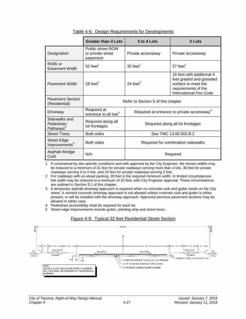
Table 4-6: Design Requirements for Developments
Greater than 4 Lots 3 to 4 Lots 2 Lots
Designation Public street ROW or private street easement
Private accessway Private accessway
ROW or Easement Width 52 feet1 32 feet1 27 feet1
Pavement Width 28 feet2 24 feet2
16 feet with additional 4 feet graded and graveled surface to meet the requirements of the International Fire Code
Pavement Section (Residential) Refer to Section 5 of this chapter
Driveway Required at entrance to all lots3 Required at entrance to private accessway3
Sidewalks and Pedestrian Pathways4
Required along all lot frontages Required along all lot frontages
Street Trees Both sides See TMC 13.06.502.B.2 Street Edge Improvements5 Both sides Required for combination sidewalks
Asphalt Wedge Curb N/A Required
1 If constrained by site-specific conditions and with approval by the City Engineer, the shown widths may be reduced to a minimum of 41 feet for private roadways serving more than 4 lots, 30 feet for private roadways serving 3 to 4 lots, and 20 feet for private roadways serving 2 lots.
2 For roadways with on-street parking, 28 feet is the required minimum width. In limited circumstances this width may be reduced to a minimum of 20 feet, with City Engineer approval. These circumstances are outlined in Section 5.1 of this chapter.
3 A temporary asphalt driveway approach is required when no concrete curb and gutter exists on the City street. A cement concrete driveway approach is not allowed unless concrete curb and gutter is either present, or will be installed with the driveway approach. Approved pervious pavement sections may be allowed in either case.
4 Pedestrian accessibility shall be required for each lot. 5 Street edge improvements include gutter, planting strip and street trees.
Figure 4-9: Typical 32 feet Residential Street Section
City of Tacoma, Right-of-Way Design Manual Issued: January 7, 2016 Chapter 4 4-27 Revised: January 11, 2018
6.8 Alleys A minimum ROW width of an alley in a residential block, when platted, shall be 20 feet. Alleys may be required in the rear of commercial and industrial districts and, where required, shall have a ROW of at least 20 feet (per TMC 13.04.200).
Improvements of alley ROW may be required when the alley is to be utilized as access to a residence, parking lot, or as otherwise directed by Traffic Engineering or the Site Development Group. Typical alley designs shall conform to Standard Plan PD-01. Incorporation of Low Impact Development BMPs is encouraged when practicable (see the SWMM).
The geometric design for alleys shall conform to the criteria as set forth in Section 2 of this chapter using a 20 mph design speed, when practicable. The typical paved width of an alley in a residential area is 16 feet with wedge curbs on both sides. When constructing a new alley that connects to existing or proposed curb and gutter, a concrete alley return conforming to City Standard Plan SU-09 shall be provided. City Standard Plan SU-09 also details the sidewalk section through the alley. Please note that for historic districts, special design standards may apply.
Figure 4-10 shows the typical alley section, which may also be used for private accessways and driveways.
Figure 4-10: Typical Alley Section
6.9 Dead Ends Dead end roadways shall not be allowed without approval of the City Traffic Engineer.
To promote connectivity, roadways shall connect with nearby existing roadways except in cases when topography, land ownership, or other factors make this infeasible. In cases when it is not feasible to connect roadways but it is feasible to establish a non-motorized pathway then the pathway shall be constructed.
In general, dead end streets shall not be longer than 500 feet. Any dead end street in excess of 150 feet in length shall terminate in a turn-around or cul-de-sac (see Sections 6.10 and 6.11). Any dead end street with four or fewer lots accessing the street may
City of Tacoma, Right-of-Way Design Manual Issued: January 7, 2016 Chapter 4 4-28 Revised: January 11, 2018
satisfy this requirement with the construction of a T-type/hammerhead or branch turn-around subject to approval by the City Engineer (see TMC 13.04.190).
Barricades with reflectors conforming to the City Standard Plan SU-13 (or approved alternate) shall be provided at dead ends, except those that terminate as a cul-de-sac. Two feet of clearance between the limits of the street improvements and the barricade shall be maintained. In areas where extreme slopes or other hazards exist, a Type 2 concrete barrier with reflectors may be utilized (see WSDOT/APWA Standard Plan C-8). Barricades or posts may not be required where a private driveway accesses the dead end street through the end of the street or turn-around.
6.10 Turn-arounds A turn-around meeting the requirements discussed within this section and the International Fire Code (IFC), shall be designed and constructed for all dead end private accessways over 150 feet in length. All public dead end streets, regardless of length, shall terminate in a turn-around that is designed and constructed to the approval of the City Engineer.
For private accessways serving 3 to 4 lots a branch or hammerhead (“T-Type”) turn-around should be constructed as shown in Figure 4-11 and Figure 4-12, respectively. For residential streets (or private accessways) serving 3 to 4 lots, a standard hammerhead turn-around should be used as shown in Figure 4-12.
Figure 4-11: Example of Branch Turn-around
Figure 4-12: Example of Hammerhead (T-Type) Turn-around
City of Tacoma, Right-of-Way Design Manual Issued: January 7, 2016 Chapter 4 4-29 Revised: January 11, 2018
6.11 Cul-de-sacs Cul-de-sacs shall be constructed where a dead end street will serve 5 or more residential lots. Cul-de-sacs are primarily constructed as permanent improvements in City ROW where the future extension of the street is not likely. The typical cul-de-sac design will include a through connection for pedestrians and bicycles to the pedestrian network in the vicinity, when appropriate for the City street network, per the Complete Street Design Guidelines.
Cul-de-sacs shall be designed to meet the minimum requirements set forth in the City Standard Plan DR-06. Typically, cul-de-sacs shall be designed with a landscaped center island or designed to accept stormwater runoff with an approved design. A standard curb or mountable curb may be used to define the inner island.
SECTION 7 Mobility Facilities
Pedestrian mobility is a vital transportation mode. Designers must be aware of the various physical needs and abilities of pedestrians in order to ensure facilities provide universal access. All pedestrian facilities as outlined in this section shall be in compliance with the ADA requirements, the design guidelines outlined in Section 1.2 of this chapter and CHAPTER 8.
7.1 Sidewalk, Amenity Zone and Buffer Widths The City minimum standard sidewalk width is 5 feet. Additional width is required in the circumstances listed below by roadway type/area.
At bus stops, a minimum 5 foot wide “connector pad” shall be provided between the curb and the edge of the sidewalk spanning the width of the associated planter strip. The distance from the face of curb to sidewalk shall be 8 feet to accommodate the access ramp deployment and associated maneuvering space. A portion of the 8 feet can be accommodated within the sidewalk if the conditions meet accessibility needs. Sidewalks adjacent to bus stops with no planter strip shall be a minimum of 8 feet wide (measured from the face of curb). The City will coordinate with the applicant to contact Pierce Transit’s Transit Development Group for more details.
7.1.1 Residential Adjacent to residential streets, sidewalk widths shall be a minimum of 5 feet, excluding the curb and buffer or planting strip. A planter strip measuring 5 feet from the face of curb to the front of walk shall be provided. If necessary and approved by the City Engineer, the planter strip may be reduced to accommodate sidewalk widening.
7.1.2 Arterials Adjacent to arterials, sidewalk widths shall be a minimum of 7 feet (excluding the curb and buffer or planting strip), unless otherwise specified in the TMC or City design guidelines. Wider sidewalks may also be required adjacent to angle parking to account for vehicle overhang.
7.1.3 Mixed-Use Centers For these high pedestrian activity areas, the City Council has directed that wider sidewalk and amenity zones be provided (see Complete Streets Mixed-Use Centers Design Guidelines). The following requirements apply either to match
City of Tacoma, Right-of-Way Design Manual Issued: January 7, 2016 Chapter 4 4-30 Revised: January 11, 2018

fully improved sidewalks or when a minimum half-block length (or 100 foot on longer frontages) site frontage improvements are being constructed.
On streets designated as pedestrian streets or primary pedestrian streets in TMC 13.06 and 13.06A respectively, a typical sidewalk width of 10 to 12 feet and an additional amenity zone width of 6 to 8 feet shall be provided. With the approval of the City Engineer, this combined total width of the sidewalk and amenity zone may be reduced to a minimum of 12 feet (excluding the curb) in order to accommodate a safety issue or unique site constraints. Reductions should be avoided if feasible on primary pedestrian streets. In all circumstances, a minimum width of no less than 7 feet shall be provided for unobstructed pedestrian passage.
7.1.4 Downtown On streets within downtown Tacoma, specific sidewalk and amenity zone widths are called out by street in the Downtown Element of the Comprehensive Plan (see Figure 4-13). In all circumstances, a minimum 7 feet shall be provided for unobstructed pedestrian passage.
Table 4-7: Downtown Tacoma – Desired Sidewalk/Amenity Zone Widths
Street Types Sidewalk/Amenity Zone Widths
Pedestrian, retail streets 15.5 feet Transit priority 14 feet Connectors 11 feet Cycling boulevards 18 feet Urban residential 10 feet Green streets 20 feet Yakima Avenue 20 feet Warehouse District Varies
7.2 Planting Area and Street Trees In accordance with City policies to establish a healthy and diverse urban forest, as defined in the Urban Forest Policy Element of the Comprehensive Plan, refer to the Urban Forest Manual (UFM) for standards that apply to all trees required by TMC 13.06.502. See CHAPTER 9 for more information.
Planting areas are located between the curb and sidewalk or behind the sidewalk. They serve as a buffer between pedestrians and vehicles, as well as provide environmental benefits. Planting areas are not allowed to be paved. Basic design elements for a planting area include the following, and may be subject to review and approval by the City Engineer or designee:
• A minimum 3 foot depth of amended existing native soil or new topsoil non-mechanically compacted to account for settling shall be provided for all newly transplanted trees, except when the tree is planted within the drip line of existing mature trees. In the case of street trees, the finished soil level including mulch (finished grade) shall be 1 inch below the adjacent pavement surface or curb. Refer
City of Tacoma, Right-of-Way Design Manual Issued: January 7, 2016 Chapter 4 4-31 Revised: January 11, 2018

to City Standard Plan LS-01, as well as the Urban Forestry Manual for minimum and recommended planting area sizes for trees.
• Planting: Plant groundcovers, perennials and shrubs with mulch covering exposed soil area. Plants (other than trees) must be less than 3 feet in mature height if planted in the public ROW.
• Mulch: Organic wood chip mulch and/or permeable inorganic mulch. Finished grade after mulch application shall be a minimum of 1 inch below the adjacent pavement surface or curb.
Figure 4-13: Downtown Tacoma Plan
City of Tacoma, Right-of-Way Design Manual Issued: January 7, 2016 Chapter 4 4-32 Revised: January 11, 2018
7.3 Curb Ramps and Crosswalks All curb ramps shall be designed and constructed to be ADA compliant in accordance with City Standard Plans and PROWAG. ADA and PROWAG requirements are discussed in CHAPTER 8. The City’s Curb Ramp Installation Matrix should also be consulted to identify the extent of curb ramp improvements related to ROW improvements.
A legal crosswalk exists at every intersection, unless it is otherwise signed. However, marked crosswalks encourage pedestrians to cross at designated locations. Some marked crosswalks are best accompanied by other treatments such as signs or beacons. Traffic Engineering must approve all new marked crosswalks (see CHAPTER 7 for more information).
7.4 Traffic Calming and Intersection Treatments Traffic calming is a way to design streets to improve safety, reduce the amount of cut-through traffic traveling on residential streets, and generally encourage people to drive slower. Traffic calming may include or be provided in conjunction with GSI features.
Although traffic calming is typically used on residential streets, there are certain tools that are appropriate for use on some arterial roadways. When a traffic calming approach is considered for any street (see Table 4-8), the City applies the following guidance:
• Vehicle speed is more critical than volume in terms of safety and should be addressed first where there are constraints.
• Neighborhood involvement is important to successful implementation. Rationale for traffic calming and management measures should be explained clearly to community residents and installation of these treatments should incorporate public input.
• Traffic calming and management measures should fit into, and preferably enhance, the street environment.
• Traffic calming designs should be predictable and easy to understand by drivers and other users.
• Devices that meet multiple goals are usually more acceptable. For example a raised crosswalk may be more understandable to motorists than a speed hump. The former has a clear goal whereas the latter may be perceived as a nuisance.
• Treatments need to be well designed and based on current available information on their applications and effects. Information on U.S. experiences with various traffic calming measures can be found in Institute of Transportation Engineers’ Traffic Calming: State of the Practice.
• Devices should accommodate emergency vehicles. Emergency response times shall be considered.
• Traffic calming areas or facilities should be adequately signed, marked, and lit to be visible to motorists.
• Treatments need to be spaced appropriately to have the desired effect on speed – too far apart and they will have a limited effect, too close and they will be an unnecessary cost and annoyance. Devices usually need to be spaced about 300 to
City of Tacoma, Right-of-Way Design Manual Issued: January 7, 2016 Chapter 4 4-33 Revised: January 11, 2018
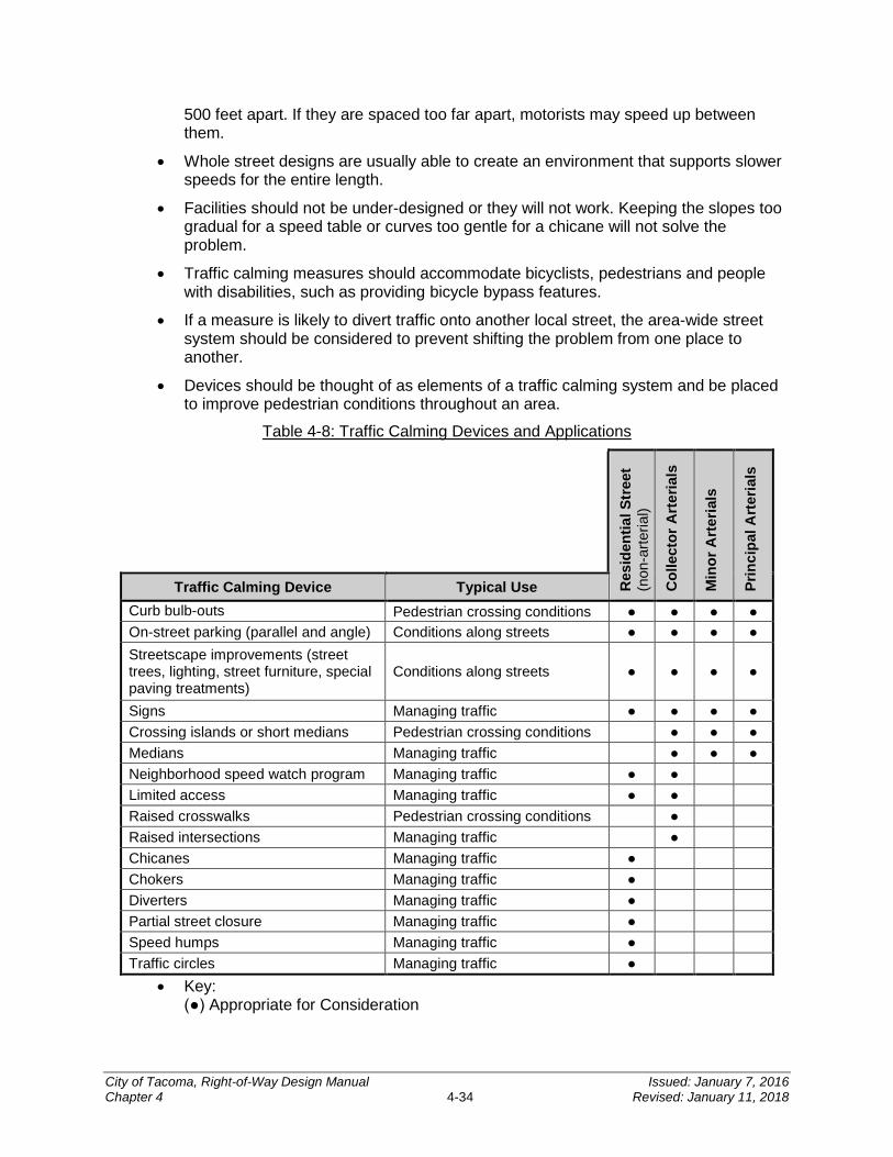
500 feet apart. If they are spaced too far apart, motorists may speed up between them.
• Whole street designs are usually able to create an environment that supports slower speeds for the entire length.
• Facilities should not be under-designed or they will not work. Keeping the slopes too gradual for a speed table or curves too gentle for a chicane will not solve the problem.
• Traffic calming measures should accommodate bicyclists, pedestrians and people with disabilities, such as providing bicycle bypass features.
• If a measure is likely to divert traffic onto another local street, the area-wide street system should be considered to prevent shifting the problem from one place to another.
• Devices should be thought of as elements of a traffic calming system and be placed to improve pedestrian conditions throughout an area.
Table 4-8: Traffic Calming Devices and Applications
Res
iden
tial S
tree
t (n
on-a
rteria
l)
Col
lect
or A
rter
ials
Min
or A
rter
ials
Prin
cipa
l Art
eria
ls
Traffic Calming Device Typical Use Curb bulb-outs
Pedestrian crossing conditions ● ● ● ● On-street parking (parallel and angle) Conditions along streets ● ● ● ● Streetscape improvements (street trees, lighting, street furniture, special paving treatments)
Conditions along streets ● ● ● ●
Signs Managing traffic ● ● ● ● Crossing islands or short medians Pedestrian crossing conditions ● ● ● Medians Managing traffic ● ● ● Neighborhood speed watch program Managing traffic ● ● Limited access Managing traffic ● ● Raised crosswalks Pedestrian crossing conditions ● Raised intersections Managing traffic ● Chicanes Managing traffic ● Chokers Managing traffic ● Diverters Managing traffic ● Partial street closure Managing traffic ● Speed humps Managing traffic ● Traffic circles Managing traffic ●
• Key: (●) Appropriate for Consideration
City of Tacoma, Right-of-Way Design Manual Issued: January 7, 2016 Chapter 4 4-34 Revised: January 11, 2018
SECTION 8 Monumentation
All new/replaced monuments constructed in a street section shall be a poured monument (see Standard Plan SU-01). Monuments shall be constructed within the limits of the permanent street improvements (located within the ROW) as follows:
• At the intersection of any two monument lines;
• At the intersection of any monument line and any section line or quarter section line;
• At the beginning and end of a horizontal curve where the point of intersection of the curve is not located within the pavement section;
• At the point of intersection of a horizontal curve where the point of intersection of the curve is located within the pavement section (excluding the curb and gutter); or
• At any horizontal angle point of the monument line.
Projects must comply with WAC 332-120 regarding locating all known survey monuments, including property corners, within the project limits. No survey monument may be removed (or replaced) without a permit being obtained in advance from the Washington State Department of Natural Resources and a copy of the permit being submitted for City acceptance. See Section 3.4 of CHAPTER 3 for guidelines on how to show monuments on standard plans.
SECTION 9 Street Amenities and Additional Design Features
9.1 Amenity Zone The amenity zone and sidewalk zone often complement one another and should be thought of as a system within a Complete Street (see Figure 4-14). Amenity zones help to buffer pedestrians from traffic and may contain many of the amenity features that contribute to an attractive and vibrant streetscape; including water features, street furniture, pedestrian lighting, street trees and vegetation, bicycle parking, loading/unloading room for on-street parking, kiosks, and public art. In constrained situations where the preferred sidewalk width is not achievable, the amenity zone can widen and enhance the sidewalk zone both visually and physically. Amenity zones may vary in width depending on available ROW. However a minimum width of 4 feet will minimize encroachment into the sidewalk zone when accommodating features such as street furniture, lighting and tree pits.
City of Tacoma, Right-of-Way Design Manual Issued: January 7, 2016 Chapter 4 4-35 Revised: January 11, 2018
The amenity zone can accommodate a range of optional enhancements or required features, which will be designed and laid out differently depending upon the available space, community priorities, available resources, and other factors. Such features must comply with applicable safety, accessibility and circulation requirements, and be designed to avoid conflicts with movement, required lines-of-sight, and traffic circulation. Design principles utilized in Crime Prevention through Environmental Design should be considered.
Objects, sidewalk cafes, and landscaping placed in the amenity zone should not encroach upon the sidewalk zone in a manner as to cause interference and unsafe conditions for the visually impaired. A minimum 7 feet of clear walking area should be provided within the sidewalk zone along arterials and high-volume pedestrian areas. Where load zones for accessible transportation and/or handicapped parking spaces are provided, the amenity zone should be clear of obstacles that might impede the loading, unloading and movement of persons with disabilities.
9.2 Signage Signage is an essential component of the streets for providing traffic control, wayfinding, as well as visual cues to all road users. A number of sign standards are applicable within the City, including the MUTCD, AASHTO, City Standard Plans, MoMaP's Bike and Pedestrian Design Guidelines, neighborhood business district standards and CHAPTER 7.
Wayfinding signage shall be included as a standard feature for the addition of bicycle facilities along a designated bicycle corridor, unless waived by the City Traffic Engineer. See CHAPTER 10 for more information regarding bicycle path signage.
9.3 Utilities Utilities of all kinds need to be accommodated within the public ROW, whether in the roadway or the sidewalk and planting strip. The following points should be considered as well as consulting with the utilities in the project area. See CHAPTER 11 and City Standard Plans DR-04 and DR-05 for information concerning wastewater and stormwater design.
• Whenever feasible, utilities and municipal infrastructure should be placed within alleys.
• Utility poles and other utility-related structures should typically be placed within the planting strip and a minimum of 5 feet unobstructed sidewalk should be maintained.
• Utility vault covers and manhole covers must have non-slip surfaces; all features shall meet ADA requirements.
• Utility structures such as switch boxes, poles, etc. should be visually integrated into the streetscape.
• Pedestrian scale lighting shall be designed and located to improve visibility and help define pedestrian areas.
• The City supports underground power lines to improve aesthetics, however a range of factors must be considered. Consult with Tacoma Power’s Transmission and Distribution at (253) 502-8277.
City of Tacoma, Right-of-Way Design Manual Issued: January 7, 2016 Chapter 4 4-36 Revised: January 11, 2018
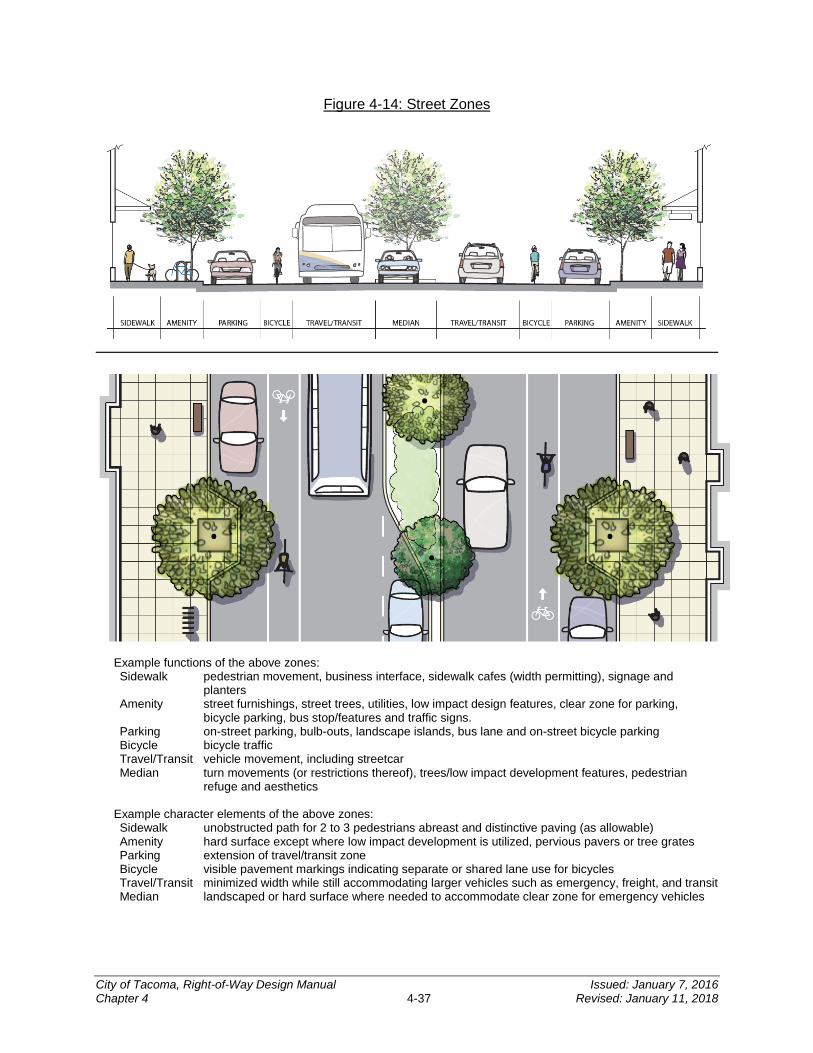
Figure 4-14: Street Zones
Example functions of the above zones: Sidewalk pedestrian movement, business interface, sidewalk cafes (width permitting), signage and
planters Amenity street furnishings, street trees, utilities, low impact design features, clear zone for parking, bicycle parking, bus stop/features and traffic signs. Parking on-street parking, bulb-outs, landscape islands, bus lane and on-street bicycle parking Bicycle bicycle traffic Travel/Transit vehicle movement, including streetcar Median turn movements (or restrictions thereof), trees/low impact development features, pedestrian
refuge and aesthetics Example character elements of the above zones: Sidewalk unobstructed path for 2 to 3 pedestrians abreast and distinctive paving (as allowable) Amenity hard surface except where low impact development is utilized, pervious pavers or tree grates Parking extension of travel/transit zone Bicycle visible pavement markings indicating separate or shared lane use for bicycles Travel/Transit minimized width while still accommodating larger vehicles such as emergency, freight, and transit Median landscaped or hard surface where needed to accommodate clear zone for emergency vehicles
City of Tacoma, Right-of-Way Design Manual Issued: January 7, 2016 Chapter 4 4-37 Revised: January 11, 2018
9.4 Street Furniture Street furniture such as benches, kiosks, newspaper stands, lighting, bicycle racks, trash bins, etc. play a major role in creating an inviting and comfortable pedestrian environment and can contribute to a neighborhood’s identity and character. Several neighborhood business districts have developed streetscape design plans that identify a street furniture palette, which should be referred to when making streetscape improvements. See CHAPTER 5 for more information about pedestrian lighting, and Section 1.2 of this chapter for Citywide Design Guidelines.
9.5 Walls Where a public wall supports fill material from entering onto the ROW, the wall shall be placed no closer than 2 feet from the back of the sidewalk or future sidewalk. In areas where a wall will be placed to support material within the ROW, care should be taken by the design engineer to provide measures that will assure the safety of both traffic and pedestrians.
Private walls shall be located at or behind the property line on private property. A Street Occupancy Permit shall be required for any private walls approved to be located within the ROW. A permit will be required for construction of a private wall within the ROW.
9.5.1 Rock Wall Rock walls are designated as a protective facing to enhance the resistance of an exposed cut or fill face to weathering and erosion. While a rock wall possesses some undetermined retention qualities due to the mass, size and shape of the rocks, it is not to be used in place of an engineered retaining wall. Under no circumstances shall a rock wall be constructed to support a surcharge from the adjacent area or improvements. Where the wall will not be affected by a surcharge, a rock wall may be constructed up to a height of 4 feet (as measured from its footing to the tallest portion of the wall) without the need for a permit or requirement to submit a design for City approval. Rock walls over 4 feet in height shall be designed by a professional licensed by the State of Washington to perform the associated work and approved by the City.
9.5.2 Engineered Retaining Wall In areas where a wall will be supporting a surcharge from an adjacent area and/or improvements, an engineered retaining wall will be required based on the following loadings:
Street: H-20
Sidewalk: 250 lbs/ft2
Concentrated Load: 8,000 lbs
Concentrated loading for sidewalks shall be distributed as specified in Table 1607.1 of the 2003 International Building Code (IBC).
9.6 Stairs, Fences, Handrails All stairs, fences and handrails shall be constructed no closer than 2 feet behind the back of sidewalk, the future back of sidewalk alignment, or the edge of the roadway, and
City of Tacoma, Right-of-Way Design Manual Issued: January 7, 2016 Chapter 4 4-38 Revised: January 11, 2018
shall meet all applicable ADA, PROWAG and other federal, state and local requirements.
Private stairs, fences and handrails shall be installed on private property whenever possible and shall only be allowed within the ROW if approved in writing by the appropriate City official. All private improvements within the ROW shall be subject to a Street Occupancy Permit and permits for construction of the improvement as applicable.
9.7 Mailboxes The applicant must contact the United States Postal Service office serving the area in order to determine the requirements with regard to mailbox access. In some instances, the design of the street section will be affected by the requirements set forth by the Postmaster General. In areas of combination walk where mailboxes are required to be adjacent to the street, the design should reflect the requirements of City Standard Plan SU-06. In areas where a Neighborhood Delivery and Collection Box Unit are required, the applicant should refer to the Postmaster General.
9.8 Bus Stops and Transit Routes Prior to applying for City permits for any development impacting existing transit stops and routes, the design engineer is responsible for a preliminary design according to the guidance from the appropriate transit agencies. The City can help the design engineer with contact information for the appropriate transit agencies upon request. Transit stop locations are restricted and controlled, through coordination of the design engineer, City, and the transit agency, to achieve maximum safety and efficiency. A minimum 5 foot by 8 foot clear area (with the 8 foot dimension extending laterally from the curb) must be provided at transit stops placed within the amenity/sidewalk zone to meet ADA/Federal Transit Agency standards.
9.9 Bike Parking The City requires long and short term bicycle parking in association with certain development activities (see TMC 13.06). The MoMaP's Bike and Pedestrian Design Guidelines apply to bicycle parking located within the public ROW.
9.10 Public Art, Civic and Cultural Features Municipal projects are subject to a one percent contribution to the City’s Municipal Art Program (see TMC 1.28B). The installation of public art and interpretive features shall be subject to the review and approval by City staff and designated City commissions. Consult with the City’s Historic Preservation Officer at (253) 591-5577 and Arts Coordinator at (253) 591-5192 to obtain guidelines applicable to public art, civic, and cultural features proposed to be located within the public ROW.
Existing features located within the public ROW can have historic or cultural significance. Prior to removal of existing features which potentially may have such significance, consult with the City’s Historic Preservation Officer.
Any proposal that would affect or is adjacent to artwork from the Municipal Art Collection shall be coordinated with the Arts Administrator. Protection during construction may be required by the City even if the artwork will not be moved or altered. Costs associated with moving, relocating or protecting art are the responsibility of the project proponent.
City of Tacoma, Right-of-Way Design Manual Issued: January 7, 2016 Chapter 4 4-39 Revised: January 11, 2018

CHAPTER 5Illumination
INTRODUCTION ..................................................................................... 5-2
SECTION 1 Illumination in the ROW ................................................ 5-3 1.1 Construction and Inspection .....................................................................................5-3 1.2 Project Completion ...................................................................................................5-3
SECTION 2 Illumination Plans .......................................................... 5-3
SECTION 3 Illumination Design ....................................................... 5-4 3.1 Lighting Zones ..........................................................................................................5-4
3.1.1 LZ0: No Ambient Lighting ................................................................................... 5-5 3.1.2 LZ1: Low Ambient Lighting ................................................................................. 5-5 3.1.3 LZ2: Moderate Ambient Lighting ......................................................................... 5-5 3.1.4 LZ3: Moderately High Ambient Lighting .............................................................. 5-5 3.1.5 LZ4: High Ambient Lighting ................................................................................. 5-5
3.2 Luminaire Spacing ....................................................................................................5-6 3.3 Typical Light Standards and Fixtures ........................................................................5-6
3.3.1 Pedestrian Ornamental Light ............................................................................... 5-7 3.4 Conduit and Electrical Design ...................................................................................5-8
SECTION 4 Electrical Service Components .................................... 5-8
5
City of Tacoma, Right-of-Way Design Manual Issued: January 7, 2016 Chapter 5 5-1 Revised: January 11, 2018
INTRODUCTION
Illumination improves both traffic safety and individual safety along streets, sidewalks, and trails by allowing for visual perception of conditions and potential hazards throughout all hours of the day. Illumination plans may be required for a variety of reasons depending on varying environments encountered throughout the City.
TMC 13.04, 13.06(A), and 13.07 provide regulatory authority for street lighting for new plats; illumination within certain zoning districts; and street lighting within landmarks and historic special review and conservation districts respectively. TMC 10.14 and 10.22 provide regulatory authority for streetlight provisions when placing or relocating driveways and when working in the ROW in general. When TMC requirements trigger offsite improvements, street lighting will also be addressed as a part of these improvements. This includes but is not limited to:
• New plats shall be required to install streetlights in accordance with TMC 13.04.165.
• New developments on arterial streets shall be required to install new streetlights or upgrade existing streetlights to current standards.
• High-density development on non-arterial streets shall be required to install new streetlights or upgrade existing streetlights to current standards when recommended by the City Traffic Engineer.
• High-density and/or commercial developments shall be required to install new streetlights or upgrade existing streetlights to current standards when recommended by the City Traffic Engineer.
• Projects in mixed-use centers and/or designated business districts shall be required to install new streetlights or upgrade existing streetlights to current standards.
• Projects on core pedestrian streets shall be required to install new streetlights or upgrade existing streetlights to current standards.
• Projects within landmarks and historic special review and conservation districts may be subject to street lighting requirements specific to that district in accordance with TMC 13.07.120.
• Projects involving undergrounding Tacoma Power’s existing overhead infrastructure on which City streetlights are mounted shall be required to upgrade streetlights to current standards.
• Low-density development for which streetlights are not required may still be required to install conduit for future streetlights where there is new or upgraded street frontage.
• New or replaced driveways and newly paved planting strips shall provide conduit for future streetlights in accordance with TMC 10.14.070.
When private funding (or third-party public funding used for development) is involved in street lighting, the permitting, design, and construction elements are an integral part of the ROW Construction/Work Order Permit, a Local Improvement District project, or a specific Capital Delivery project as applicable. Third-party design and implementation of City-owned streetlight infrastructure must be closely coordinated with Traffic Engineering throughout the process and shall conform to the design requirements in this section.
City of Tacoma, Right-of-Way Design Manual Issued: January 7, 2016 Chapter 5 5-2 Revised: January 11, 2018
SECTION 1 Illumination in the ROW
1.1 Construction and Inspection Unless changed through a formal agreement, streetlights in the public ROW shall be owned and maintained by the City. Lighting along private streets and other lighting outside of the public ROW shall be owned and maintained by the property owners or association.
All construction shall be in conformance with National Electric Code and the WSDOT Standard Specifications as supplemented or amended by the Washington State Chapter of APWA or the City of Tacoma General Special Provisions.
All electrical work in the ROW shall be performed by a licensed electrical contractor for the installation of the streetlights. The applicant will also be responsible for project management; including scheduling and coordinating work between the various contractors and utilities. Additionally, the applicant shall be responsible for coordinating the location of underground utilities and identifying conflicts in the location of these utilities. Before beginning work, the City will locate all underground streetlight utilities as a part of the one-call service at 811.
The contractor shall notify the City Streetlight Inspection staff for inspection of the work:
• Before conduit is buried;
• Before placing streetlight, service, or cabinet foundations (“Ufer,” supplemental grounding, and all grounding connections must be in place);
• Before placing concrete adjacent to junction boxes (the contractor is responsible for determining proper grades);
• When construction is substantially complete; and
• As a part of final inspection of the streetlight system.
1.2 Project Completion Before project closeout, the City will notify the applicant that the final inspection has passed and that the City has found the street lighting complete and operational. At this time, the ownership, operation and maintenance of the public lights shall transfer to the City.
Acceptance of the street lighting system is one of the requirements for final plat approval.
SECTION 2 Illumination Plans
The design engineer should refer to CHAPTER 3 for general requirements regarding the plan format.
Plan sheets for a ROW Construction/Work Order Permits involving illumination shall show all existing features and identify all pavement removal. The plans shall provide a lighting layout plan and show all applicable details on the plan. Details include but are not limited to:
• Location of sidewalks, curb ramps, and other proposed roadway features;
City of Tacoma, Right-of-Way Design Manual Issued: January 7, 2016 Chapter 5 5-3 Revised: January 11, 2018

• Above- and below-ground utilities;
• Street trees to remain;
• General, wire, and pole notes;
• Service connections coordinated with Traffic Engineering;
• Any intersection signalization; and
• Proposed location of junction boxes.
Where applicable, the plan shall also provide a service/circuit schematic and wiring diagram, and wiring and illumination pole schedules (complete with foundation, mounting, and fixture information).
SECTION 3 Illumination Design
Illumination design has evolved over time. The existing illumination in the project area shall be assessed in relation to current design practices.
Illumination in the ROW must meet design criteria described in the latest version of Illuminating Engineering Society of North America’s (IES) American National Standard Practice for Roadway Lighting (IESNA RP-8) or AASHTO’s Roadway Lighting Design Guide Pavement classification. Road and pedestrian conflict areas, and other design assumptions must be clearly stated in the illumination memo or photometric plan sheet.
Other design criteria may be substituted in specific cases when approved by the City Traffic Engineer.
When designing a bicycle or shared-use path as a separate facility (reference CHAPTER 10), areas of low pedestrian conflict shall have a uniformity ratio of 4:1 or better along the path. Where the path intersects a roadway of any classification, the uniformity ratio shall not be less than 3:1. All other design criteria for paths constructed as a separate facility shall be in conformance with the IESNA RP-8 or AASHTO’s Roadway Lighting Design Guide as stated above.
When a photometric analysis is provided, luminaire fixture types, mounting heights and locations (pole and luminaire arm length) must be labeled accordingly in the document.
AGi32 is the preferred and recommended software for illumination analysis. When AGi32 is utilized, electronic project files shall be submitted to the City Traffic Engineering section.
3.1 Lighting Zones Illumination in the ROW shall meet the project design criteria as determined above, but not to the detriment of the surrounding property, land use context, and environment. Light trespass outside of the project area, either across property lines or wasted upward, shall be addressed. At a minimum, the surrounding uses will require Backlight, Uplight, Glare (BUG) ratings to be specified in the project plans in accordance with this section.
BUG ratings are defined by the IES to classify light fixtures based on the percentage of light emanating in specific directions from the fixture. The lower a rating the less light escapes creating backlight, uplight, and glare respectively. The higher a rating, the less desirable the fixture is when considering the surrounding environment.
City of Tacoma, Right-of-Way Design Manual Issued: January 7, 2016 Chapter 5 5-4 Revised: January 11, 2018
To determine appropriate BUG ratings for specific projects, consider the adjacent property. A Lighting Zone (LZ) classifies areas based on their tolerance for light trespass.
IES generally defines five LZs:
3.1.1 LZ0: No Ambient Lighting Applied to areas where the natural environment will be seriously and adversely affected by lighting. Impacts include disturbing the biological cycles of flora and fauna and/or detracting from human enjoyment and appreciation of the natural environment. For these areas, human activity is subordinate in importance to nature. The vision of human residents and users is adapted to the darkness, and they expect to see little or no lighting. When not needed, lighting should be extinguished.
3.1.2 LZ1: Low Ambient Lighting Applied to areas where lighting might adversely affect flora and fauna or disturb the character of the area. The vision of human residents and users is adapted to low light levels. Lighting may be used for safety and convenience but it is not necessarily uniform or continuous. After curfew, most lighting should be extinguished or reduced as activity levels decline.
3.1.3 LZ2: Moderate Ambient Lighting Applied to areas of human activity where the vision of human residents and users is adapted to moderate light levels. Lighting may typically be used for safety and convenience but it is not necessarily uniform or continuous. After curfew, lighting may be extinguished or reduced as activity levels decline.
3.1.4 LZ3: Moderately High Ambient Lighting Applied to areas of human activity where the vision of human residents and users is adapted to moderately high light levels. Lighting is generally desired for safety, security and/or convenience and it is often uniform and/or continuous. After curfew, lighting may be extinguished or reduced in most areas as activity levels decline.
3.1.5 LZ4: High Ambient Lighting Applied to areas of human activity where the vision of human residents and users is adapted to high light levels. Lighting is generally considered necessary for safety, security and/or convenience and it is mostly uniform and/or continuous. After curfew, lighting may be extinguished or reduced in some areas as activity levels decline.
As shown in Table 5-1, lighting in the ROW shall meet the following BUG ratings where adjacent to the following LZs. For projects spanning multiple LZs, consult with Traffic Engineering to determine rating. Additional back cut-offs/shields shall only be utilized as allowed by Traffic Engineering and per manufacturer’s recommendations.
City of Tacoma, Right-of-Way Design Manual Issued: January 7, 2016 Chapter 5 5-5 Revised: January 11, 2018
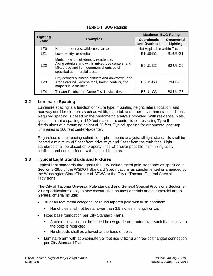
Table 5-1: BUG Ratings
Lighting Zone Examples
Maximum BUG Rating Cobraheads
and Overhead Ornamental
Lighting LZ0 Nature preserves, wilderness areas Not Applicable within Tacoma LZ1 Low-density residential B1-U0-G1 B1-U3-G1
LZ2
Medium- and high-density residential; Along arterials and within mixed-use centers; and Mixed-use and light commercial outside of specified commercial areas.
B2-U1-G2 B2-U3-G2
LZ3 City-defined business districts and downtown; and Areas around Tacoma Mall, transit centers, and major public facilities.
B3-U1-G3 B3-U3-G3
LZ4 Theater District and Dome District vicinities B3-U1-G3 B3-U4-G3 3.2 Luminaire Spacing
Luminaire spacing is a function of fixture type, mounting height, lateral location, and roadway corridor elements such as width, material, and other environmental conditions. Required spacing is based on the photometric analysis provided. With residential plats, typical luminaire spacing is 150 feet maximum, center-to-center, using Type II distributions at a mounting height of 30 feet. Typical spacing for ornamental post-top luminaires is 100 feet center-to-center.
Regardless of the spacing schedule or photometric analysis, all light standards shall be located a minimum of 5 feet from driveways and 3 feet from the curb face. Light standards shall be placed on property lines whenever possible, minimizing utility conflicts, and not interfering with accessible paths.
3.3 Typical Light Standards and Fixtures Typical light standards throughout the City include metal pole standards as specified in Section 9-29.6 of the WSDOT Standard Specifications as supplemented or amended by the Washington State Chapter of APWA or the City of Tacoma General Special Provisions.
The City of Tacoma Universal Pole standard and General Special Provisions Section 9-29.6 specifications apply to new construction on most arterials and commercial areas. General criteria include:
• 30 or 40 foot metal octagonal or round tapered pole with flush handhole.
Handholes shall not be narrower than 3.5 inches in length or width.
• Fixed base foundation per City Standard Plans.
Anchor bolts shall not be buried below grade or grouted over such that access to the bolts is restricted.
No shrouds shall be allowed at the base of pole.
• Luminaire arm with approximately 2 foot rise utilizing a three-bolt flanged connection per City Standard Plans.
City of Tacoma, Right-of-Way Design Manual Issued: January 7, 2016 Chapter 5 5-6 Revised: January 11, 2018
Banding or clamp-style attachments to poles will not be permitted unless approved by the City Traffic Engineer.
• Rain-tight pole cap.
On all new construction and when replacing existing fixtures, LED lights shall be used unless otherwise approved by the City Traffic Engineer. Due to the rapidly evolving LED market, please contact Traffic Engineering for a current list of acceptable fixtures. At the time of this publication, all LED cobrahead fixtures shall be one of the following unless otherwise approved:
• Beta/Cree – XSP™/XSPR™ series and LEDway® series
• Leotek® – GreenCobra™ series
• GE – Evolve™ series
• American Electric Lighting®/Holophane® – Autobahn series
All fixtures shall have the following features:
• Tool-less entry
• National Electrical Manufacturers Association® (NEMA) 7-pin LED-compatible Photocell Receptacle
Photocell shall have a 20 year design life
• Time Delay Fuse (in fixture for overhead cobrahead lighting)
Fusing at the base is reserved for installations which cannot accommodate in-head fuses such as ornamental light standards
Fixture optics shall meet the following criteria:
• Color correlated temperature from 4000 K to 5300 K
• Minimum color rendering index of 70
• See Section 3.1 for BUG ratings
When timber poles are allowed by the City Traffic Engineer, they shall be Class II with single-point luminaire arm connections per City Standard Plans. When attaching a cobrahead luminaire to an existing utility pole, City crews will perform that body of work at the applicant’s expense.
3.3.1 Pedestrian Ornamental Light The standard pedestrian-scale ornamental light consists of an exposed-aggregate concrete post (13 feet, direct bury with 3 inch tenon) topped with a Holophane® GranVille® II LED Classic Standard:
• Housing – black GranVille II LED with leaf style swing open design (3 inch diameter tenon)
• Accessories – black standard finial without trim
• Auto-sensing voltage (120-277 V) with wattage based on design
• 4000K color temperature with optics pattern based on design
City of Tacoma, Right-of-Way Design Manual Issued: January 7, 2016 Chapter 5 5-7 Revised: January 11, 2018
Otherwise, certain neighborhood business districts, mixed-use centers, and historic/residential areas have specific decorative light standards unique to the designated area. Coordinate with the City Traffic Engineer for specific use of light standards in these areas. Use of LED ornamental lights in these areas shall be approved by the City Traffic Engineer prior to incorporation into the project. A product sample may be required to access quality, durability, and ease of maintenance.
3.4 Conduit and Electrical Design The City still has series lighting circuits in some areas. Contact Traffic Engineering before beginning any electrical design.
All streetlight conductors shall meet the requirements of Section 9-29 of the WSDOT Standard Specifications as supplemented or amended by the Washington State Chapter of APWA or the City of Tacoma General Special Provisions.
All streetlight conduit shall be 1¼ inch in diameter. Conduit installed under streets and commercial driveways shall be Polyvinyl Chloride (PVC) Schedule 80 pipe. Conduit installed behind the sidewalk shall be PVC Schedule 40 pipe. Refer to Sections 8-20.3(5) and 9-29.1 of the WSDOT Standard Specifications as supplemented or amended by the Washington State Chapter of APWA or the City of Tacoma General Special Provisions for construction and material details, respectively.
Voltage drop calculations shall be provided for each lighting circuit. Each streetlight circuit should have a maximum of 20 lights unless otherwise approved. Wire shall be maximum #6 gauge or minimum #8 gauge stranded copper wire unless otherwise approved.
Traffic signal controller service wire and streetlight wire may share a conduit and junction box.
Junction boxes shall meet the requirements of Section 9-29.2 of the WSDOT Standard Specifications as supplemented or amended by the Washington State Chapter of APWA or the City of Tacoma General Special Provisions. A WSDOT Type 1 standard duty junction box with alternative 2 locking lid shall be utilized per WSDOT Standard Plan J-40.10-03, unless otherwise approved by the City Traffic Engineer.
Junction boxes shall be provided at each end of a roadway crossing and within several feet of each streetlight pole, no matter the pole spacing.
SECTION 4 Electrical Service Components
Service enclosures and load centers shall be exterior (NEMA 3R) rated. Unless power outlets or other equipment unrelated to illumination in the ROW are connected to the City’s streetlight circuits, a power meter shall not be provided.
All electrical services must conform to National Electrical Code and the WSDOT Standard Specifications as supplemented or amended by the Washington State Chapter of APWA or the City of Tacoma General Special Provisions. A preapproved list of equipment can be obtained from Traffic Engineering.
City of Tacoma, Right-of-Way Design Manual Issued: January 7, 2016 Chapter 5 5-8 Revised: January 11, 2018
CHAPTER 6Traffic Signalization
INTRODUCTION ..................................................................................... 6-2
SECTION 1 Permitting for Warning Beacons and Traffic Signalization ........................................................................................ 6-2
1.1 Construction and Inspection .....................................................................................6-2 1.2 Project Completion ...................................................................................................6-2
SECTION 2 Traffic Signalization Plans ............................................ 6-3
SECTION 3 Signalization Design...................................................... 6-3 3.1 Typical Signal Supports ............................................................................................6-3 3.2 Typical Signal Displays .............................................................................................6-4 3.3 Vehicular Detection Systems ....................................................................................6-5 3.4 Pedestrian Systems ..................................................................................................6-6 3.5 Preemption Systems.................................................................................................6-6 3.6 Conduit System ........................................................................................................6-7 3.7 Junction Boxes .........................................................................................................6-7 3.8 Wire Specifications ...................................................................................................6-8 3.9 Traffic Signal Controls, Cabinets, and Components ..................................................6-8 3.10 Interconnect and Communications ............................................................................6-9
SECTION 4 Warning Beacons .......................................................... 6-9 4.1 Pedestrian-Actuated Warning Beacons ....................................................................6-9 4.2 Continuously-Operating Warning Beacons ...............................................................6-9
SECTION 5 Electrical Service ......................................................... 6-10
6
City of Tacoma, Right-of-Way Design Manual Issued: January 7, 2016 Chapter 6 6-1 Revised: January 11, 2018
INTRODUCTION
Traffic signals and warning beacons are the most accepted and widely used traffic control devices approved by FHWA and the MUTCD when conveying ROW and other traffic control messages at more traveled at-grade intersections/conflict points in any corridor open to public use. Their reliability and consistency in appearance and application is a vital part of maintaining a safe public ROW for all users. TMC Title 10 and Title 11 establish additional authority for permitting and specific uses of these facilities in the City.
Third-party design and implementation of City-owned traffic signal infrastructure must be closely coordinated with Traffic Engineering throughout the process.
Private and public projects shall follow the design requirements and policy stated and referenced herein.
For all signal work, no matter how limited the scope, the design engineer is encouraged to schedule a pre-design meeting with Traffic Engineering to review specific traffic signalization design requirements.
For all construction involving arterial roadways and/or curb ramps, a pre-design meeting with Traffic Engineering and the ADA Coordinator is required to discuss accessible pedestrian signals (APS) (e.g., pushbutton) needs and potential issues between pedestrian circulation and electrical equipment.
SECTION 1 Permitting for Warning Beacons and Traffic Signalization
1.1 Construction and Inspection All construction shall be in conformance with National Electric Code and the WSDOT Standard Specifications as supplemented or amended by the Washington State Chapter of APWA or the City of Tacoma General Special Provisions. All construction must be performed by a licensed electrical contractor.
A City Traffic Signal Inspector will be assigned to inspect the traffic signalization project and assist the assigned City Construction Inspector. All signal equipment shall be field located by the City Traffic Signal Inspector.
Controller equipment purchased by the applicant shall be delivered to the City Signal Shop for testing prior to installation. All cabinet hardware shall be tested, programmed, and landed by City staff at the expense of the project.
1.2 Project Completion The applicant shall provide warranty(s) for all electrical and mechanical equipment, and strain poles and signal standards for satisfactory service operation for one year following project acceptance. Warranty shall include troubleshooting, labor, materials and all other costs to bring the equipment to a satisfactory level of service. Normal maintenance is not included in the warranty.
City of Tacoma, Right-of-Way Design Manual Issued: January 7, 2016 Chapter 6 6-2 Revised: January 11, 2018
SECTION 2 Traffic Signalization Plans
The design engineer should refer to CHAPTER 3 for general requirements regarding the plan format.
Plan sheets for a ROW Construction/Work Order Permits involving traffic signalization shall show all existing features and identify all pavement removal. The plans shall provide a traffic signalization plan and show all applicable details on the plan. Details include but are not limited to:
• Proposed channelization;
• Sidewalks and curb ramps;
• Above and below ground utilities;
• Detection devices;
• Signal phasing diagram per standard;
• Preemption requirements;
• Intersection illumination; and
• Any available speed and traffic information.
Where applicable, the plan shall also provide a signal schematic and wiring diagram, signal mast arm/pole attachment, and foundation design schedules.
SECTION 3 Signalization Design
Traffic signal design in the city shall conform to MUTCD, state, and federal law requirements; the latest AASHTO Policy; National Electrical Code; and all applicable City of Tacoma General Special Provisions and Standard Plans. Construction and material details concerning signalization design are contained in Section 8-20 and 9-29 of the WSDOT Standard Specifications as supplemented or amended by the Washington State Chapter of APWA or the City of Tacoma General Special Provisions.
3.1 Typical Signal Supports The standard traffic signal design consists of cantilevered mast arm signal poles with luminaire extensions (WSDOT Type 3) surrounded by other satellite posts to meet ADA and MUTCD standards (WSDOT Types PPB and 1). Other standards may be approved by the City Traffic Engineer for specific applications, such as vertical shaft standards for shoulder-mounted displays (WSDOT Type 1) and strain poles for span wire installation (WSDOT Types 4 and 5).
All new signals or an existing signal rebuild shall be mast arm construction unless a detailed cost estimate submitted for review shows the estimated mast arm replacement costs more than 20 percent over rebuilding those existing components.
Pole placement should consider competing factors, such as utility conflicts (both above and below ground), roadside clearance, minimizing mast arm length, construction feasibility (present and future plans), ease of maintenance, and ADA/pedestrian access effects, while meeting signal face visibility requirements in the MUTCD.
City of Tacoma, Right-of-Way Design Manual Issued: January 7, 2016 Chapter 6 6-3 Revised: January 11, 2018
A minimum 10 foot clearance is required from overhead power systems rated 50 kilovolts or below. Additional clearance is required for higher voltages.
Most poles and their attachments should not be located within 3 feet of the curb face or within 5 feet of a driveway. Pedestrian pushbutton poles shall not be closer than 5 feet to the curb face unless approved by the City Traffic Engineer.
Any poles used for pedestrian pushbuttons should be located within 5 feet of the extension of the crosswalk line and within 6 feet of the curb face when feasible. When 6 feet from the curb face is not feasible, all pushbuttons shall be mounted within 10 feet of the curb face. See Section 3.4 of this chapter for more information.
Mast arm length should be kept to a minimum, and designs exceeding 50 feet will require preapproval by the City Traffic Engineer. Mast arm length and pole placement should consider future signal phasing, lane configurations, and equipment upgrades. Poles should be placed so technicians working in and around them are not unduly exposed to traffic and other hazards. Handholes should be accessible to staff, but secure. The head of handhold security bolt must be flush with face of plate, and the face plate of handhole must be flush with pole.
Poles supporting multiple traffic signal appurtenances should be considered as long as mounting locations for specific federal requirements are not compromised. Three poles on any one intersection corner should be feasible in most applications, e.g., two pushbutton posts and one mast arm support with all signal displays or two Type I poles with a pushbutton and pedestrian signal each and one mast arm support with no pedestrian appurtenances.
Poles mounted for the primary vehicular signals should allow those signals to be located between 40 feet and 180 feet of the stop bar location.
For specific foundation and attachment details, see the City of Tacoma Standard Plans and WSDOT Standard Plans.
3.2 Typical Signal Displays Traffic signal displays must conform to the WSDOT Standard Specifications as supplemented or amended by the Washington State Chapter of APWA or the City of Tacoma General Special Provisions, and other applicable WSDOT and MUTCD requirements.
Two separate indications for the primary movement on each approach shall be provided. Vehicular signal heads should be placed overhead in line with the applicable vehicular movement into the intersection where feasible, but mounted no closer than 8 feet from other signal heads. Turning/shared-face vehicle signal heads may be placed over the applicable lane line. Care should be taken to avoid blocking another approach’s signal faces.
Bimodal vehicular signal heads shall not be utilized unless otherwise approved by the City Traffic Engineer. All vehicular indications shall be 12 inch LED, and all signal heads shall have aluminum housing. All new signal heads installed on mast arms shall have backplates with a 1 inch wide yellow border and be attached using a WSDOT Type M mount.
City of Tacoma, Right-of-Way Design Manual Issued: January 7, 2016 Chapter 6 6-4 Revised: January 11, 2018
LED 8 inch displays are reserved for specific uses such as bike only indications, emergency signals, warning beacons, and as otherwise approved by the City Traffic Engineer.
When a left-turn protective/permissive phase is added as part of a traffic signal modification or on new construction, the indication shall be a flashing yellow arrow, unless otherwise approved by the City Traffic Engineer.
Pedestrian signal heads shall conform to Section 9-29.20 of the WSDOT Standard Specifications as supplemented or amended by the Washington State Chapter of APWA or the City of Tacoma General Special Provisions. New pedestrian signals shall utilize an aluminum housing, single-section clamshell-style mount with hand/man indications accompanied by a countdown display during the “don’t walk” interval.
Pedestrian signal heads shall be located between 7 and 10 feet above the receiving sidewalk area and clearly visible from the opposite curb ramp area served by the pedestrian signal.
3.3 Vehicular Detection Systems New detection systems should be non-intrusive and aerial-mounted, selected in coordination with the City Traffic Engineering section. All new and modified detection systems shall be capable of bicycle detection to comply with RCW 47.36.025. Detection systems shall conform to Section 9-29.18 of the WSDOT Standard Specifications as supplemented or amended by the Washington State Chapter of APWA or the City of Tacoma General Special Provisions.
Acceptable detection systems include:
• Thermal detection: FLIR® camera with Traficon in-cabinet hardware
• Infrared detection: Leddar™ d-tec system
• Microwave detection: Wavetronix SmartSensor Matrix™ system
• Fisheye camera detection: Aldis™ GridSmart® system
Not all systems work well in all locations; it varies based on topography and other environmental conditions. The designer should analyze the design constraints specific to the intersection and provide the best system for the application. A letter should be provided from the manufacturer/supplier certifying that the physical conditions do not prohibit the proper performance of the proposed system.
Replacement of existing induction loops will be allowed for modifications to existing signal locations involving four or fewer affected loops. However, wireless in-road detection systems such as the Sensys Networks Incorporated system are the preferred replacements to induction loops when non-intrusive systems cannot be used. Loops shall be placed only in new asphalt, new concrete or a section receiving a minimum 2 inch overlay.
A fee in lieu of loop replacement, based on the estimated replacement costs, may be an option for the applicant for certain situations. Contact Traffic Engineering at (253) 573-2332 to discuss this topic.
City of Tacoma, Right-of-Way Design Manual Issued: January 7, 2016 Chapter 6 6-5 Revised: January 11, 2018
When Sensys Networks Incorporated system is the selected option, the MicroRadar® sensor must be used for stopbar detection (VSN240-M per manufacturer’s recommendations) and magnetometers may be used for other detection zones (VSN240-T).
When five or more affected induction loops are concentrated on a single intersection approach, a non-intrusive device should be used to replace the entire approach’s detection.
Consideration should be given to the amount of room in the controller cabinet to accommodate the detection system. At some existing traffic signal locations, an upgrade to a P-sized cabinet may be required.
3.4 Pedestrian Systems When prescribed by City ADA policy and PROWAG, new pedestrian systems shall be fully compliant with MUTCD and PROWAG APS requirements. See CHAPTER 8 for additional information about ADA and pedestrian facility design.
As stated in Section 3.1 of this chapter, pole and support locations shall allow for pedestrian pushbuttons to be located per MUTCD and ADA standards. For optimal maintenance and use:
• Pushbutton posts shall be located a minimum of 5 feet from the curb face. Placement as close as 1.5 feet from the curb face will be allowed if it is demonstrated during design to be protected from potential knockdown and damage. Placement greater than 10 feet from the curb face will not be allowed.
• Pushbuttons shall be located within 5 feet of the extension of the crosswalk line and within reach of an ADA-compliant clear space, see CHAPTER 8.
• Target height is 3.5 feet above grade; 4 feet is the maximum height.
• All pushbuttons shall be oriented with the face of pushbutton and sign assembly parallel to the corresponding crosswalk
• New pedestrian signage at the pushbutton shall include MUTCD’s R10-3b sign at 9 inches by 12 inches.
The new APS system must be programmable and customizable by the end user with in-cabinet controls. The APS system must be capable of providing user-programmed vocal messages. Four-wire connection to controls in pedestrian heads is not allowed.
Consideration should be given to the amount of room in the controller cabinet to accommodate the APS system. At some existing traffic signal locations, an upgrade to a P-sized cabinet may be required.
3.5 Preemption Systems All signalized intersections must have emergency preemption systems. Emergency preemption systems shall utilize Opticom™ 700 Series Detectors, Model 760 Card Racks, and Model 764 Multimode Phase Selectors.
Rail and transit preemption systems must be designed in coordination with the City Traffic Engineering section.
City of Tacoma, Right-of-Way Design Manual Issued: January 7, 2016 Chapter 6 6-6 Revised: January 11, 2018
3.6 Conduit System Conduit must conform to the WSDOT Standard Specifications as supplemented or amended by the Washington State Chapter of APWA or the City of Tacoma General Special Provisions.
All traffic signal conduit shall be 2 inch, except 1 inch conduit will be allowed when only a pushbutton post with one pushbutton is served. Conduit installed under streets and commercial driveways shall be PVC Schedule 80 pipe. Conduit installed behind the sidewalk shall be PVC Schedule 40 pipe.
Typically, install four 2 inch traffic signal conduits and one 1¼ inch streetlight conduit for each street crossing. However, conduit fill calculations must be provided and verified by the designer.
3.7 Junction Boxes Junction boxes shall meet the requirements of Section 9-29 of the WSDOT Standard Specifications as supplemented or amended by the Washington State Chapter of APWA or the City of Tacoma General Special Provisions.
All new/replaced junction boxes must meet one of the following criteria:
• WSDOT Type 1 standard duty junction box with alternative 2 locking lid shall be utilized per WSDOT Standard Plan J-40.10.
• WSDOT Type 2 standard duty junction box with alternative 2 locking lid shall be utilized per state WSDOT Standard Plan J-40.10 where connecting interconnect cable/conduit.
• Junction boxes exposed to vehicular traffic shall be heavy duty. Junction boxes installed within an intersection radius and within 4 feet of the curb face shall be heavy duty unless otherwise approved. If a heavy duty junction box is proposed within a sidewalk section, a meeting with Traffic Engineering and ADA Coordinator is required to coordinate its location in relation to the PAR.
• Junction boxes larger than outlined above may only be utilized with prior approval from the City Traffic Engineer.
Junction boxes shall be provided at each end of a roadway crossing and within several feet of each pole, cabinet, and signal appurtenance to be served by conduit in the signal system. Junction boxes should be kept outside of the PAR but still adjacent the sidewalk or other paved surface. Any junction box located in the PAR must have an ADA slip-resistant lid as defined by applicable WSDOT Standard Specifications.
Standard size junction boxes shall be installed at the base of the pole for all service riser assemblies. Additionally, ground rod boxes are required for service riser assemblies. Standard size junction boxes shall also be installed at the base of the pole for a communication riser assembly prior to entering the controller foundation due to the length of the run and/or drainage considerations.
Relocating junction boxes at a signalized intersection to avoid ADA curb ramp installation should be a last resort due to the amount of rewiring required.
City of Tacoma, Right-of-Way Design Manual Issued: January 7, 2016 Chapter 6 6-7 Revised: January 11, 2018
3.8 Wire Specifications All traffic signal and streetlight conductors and cable shall meet the requirements of Section 9-29.3 of the WSDOT Standard Specifications as supplemented or amended by the Washington State Chapter of APWA or the City of Tacoma General Special Provisions.
Traffic signal controller service wire and streetlight wire may share a conduit and junction box.
Low voltage traffic signal cable consists of detection cable, interconnect cable, and pedestrian pushbutton cable. Unless otherwise directed by the City Traffic Engineer, low voltage traffic signal wiring may be combined in a single vault/junction box with 5-conductor cable for traffic signal heads and other high voltage equipment.
A separate ground wire shall be installed in every conduit run.
All signal wiring shall be 5 conductor or 2 conductor, 14 gauge stranded wire as described below:
• All wiring to signal heads shall be 5 conductor wire. For 5 section signal heads and bimodal (where approved) 2-5 conductor, 14 gauge wire shall be utilized.
• 5 conductor wire may not be split for high and low voltage in a single cable; separate 2 conductor shall be pulled for pushbuttons when sharing a common pole with a pedestrian head.
• A single 5 conductor wire may be split between 2 pedestrian heads on a common pole with a jumper across the neutral.
Opticom™ and detection wiring shall be per manufacturer’s recommendations.
Splices of communication cable are not allowed. When communication cable or part of the interconnect system has been affected or compromised by construction, a new un-spliced communication cable shall be installed between cabinets.
3.9 Traffic Signal Controls, Cabinets, and Components For traffic signal interoperability and in the interest of the traveling public and City investment, standardization of traffic signal cabinets and controllers is necessary. All traffic signal controller housings and components shall meet the requirements of Section 9-29 of the WSDOT Standard Specifications as supplemented or amended by the Washington State Chapter of APWA or the City of Tacoma General Special Provisions. Specific equipment and requirements at this time include:
• Controller: Siemens M60 – Contact the City Signal Shop at (253) 591-5287 to obtain the current firmware version
• Malfunction Management Unit shall be:
Peek Double Diamond, Model TS2-MMU Eberle Design Inc., Model MMU-16LEip SmartMonitor® (where approved) Reno A&E, Model MMU-1600GE (where approved)
NEMA TS2, Type 2 P44 cabinets are required. A level area of 4 feet clearance shall be provided in front of cabinet opening as a safe work space for signal technicians. The
City of Tacoma, Right-of-Way Design Manual Issued: January 7, 2016 Chapter 6 6-8 Revised: January 11, 2018

location and orientation of the cabinet shall allow for a clear view of the intersection while the technician is working and shall not allow the open cabinet door to interfere with pedestrian circulation or otherwise cause a potential hazard to the signal technician and the public.
An uninterruptible power supply battery backup system will be installed at signals within 300 feet of rail lines, along school walking routes, and at other high volume and high risk locations as determined by the City Traffic Engineer. See the City of Tacoma General Special Provisions for additional cabinet requirements.
3.10 Interconnect and Communications Traffic signal communication systems and hardware shall conform to the following unless otherwise required by the design:
• Conduit shall be 2 inches in diameter at a minimum with 24 inch sweeps.
• WSDOT Type 2 junction boxes for traffic signal interconnect.
• Maximum 300 feet between pull locations.
• Ethernet over copper switch – Actelis Networks ML684D with two SFP-LC ports or ML698 where four-way communication is required.
New signals shall be physically connected underground and incorporated into the existing communications network.
SECTION 4 Warning Beacons
The method and type of warning beacon installation varies according to desired purpose. Selection of appropriate devices and their applications shall be coordinated with Traffic Engineering.
4.1 Pedestrian-Actuated Warning Beacons New installations of pedestrian-actuated warning beacons must utilize rectangular rapid flashing beacons (RRFBs) as interimly-approved by WSDOT and the FHWA. JSF Technologies’ AB-9405 and compatible pushbuttons should be used for most applications. Additional emphasis as determined by the City Traffic Engineer may necessitate use of JSF Technologies’ AB-9407 or an approved equal. Pushbuttons shall be located and oriented to meet ADA and MUTCD requirements. Selection of mounting equipment and posts should be coordinated with Traffic Engineering and the City Signal Shop.
Warning beacons in advance of the pedestrian crossing shall not be RRFB, but they must communicate with the RRFB system to ensure concurrent operation. They shall be circular and in accordance with MUTCD requirements.
4.2 Continuously-Operating Warning Beacons Warning beacons in continual flashing operation shall be circular and in accordance with MUTCD requirements. They include red stop beacons, school beacons, overhead crosswalk beacons, and other yellow warning beacons. Selection of mounting equipment and posts should be coordinated with Traffic Engineering and the City Signal Shop.
City of Tacoma, Right-of-Way Design Manual Issued: January 7, 2016 Chapter 6 6-9 Revised: January 11, 2018
SECTION 5 Electrical Service
Service enclosures and load centers shall be exterior (NEMA 3R) rated. Unless power outlets or other equipment unrelated to signalization are connected to the City’s circuit, a power meter shall not be provided.
All electrical services must conform to National Electrical Code and the WSDOT Standard Specifications as supplemented or amended by the Washington State Chapter of APWA or the City of Tacoma General Special Provisions. A preapproved list of equipment can be obtained from Traffic Engineering.
City of Tacoma, Right-of-Way Design Manual Issued: January 7, 2016 Chapter 6 6-10 Revised: January 11, 2018
CHAPTER 7Channelization and Signing
INTRODUCTION ..................................................................................... 7-2
SECTION 1 Project Initiation ............................................................ 7-2 1.1 Project Scope ...........................................................................................................7-2 1.2 Identification of Design Elements ..............................................................................7-2 1.3 Design Coordination .................................................................................................7-3
SECTION 2 Documentation of Conditions ....................................... 7-4 2.1 Site Visit ...................................................................................................................7-4 2.2 Inventory of Existing Elements ..................................................................................7-4 2.3 Identification of Project Extents .................................................................................7-4
SECTION 3 Plans Preparation .......................................................... 7-5 3.1 General Requirements ..............................................................................................7-5 3.2 Plan Sheet Content ..................................................................................................7-5 3.3 Design Guidance ......................................................................................................7-6
3.3.1 Crosswalk Installation .......................................................................................... 7-6 3.3.2 Candidate Sites for Marked Crosswalks .............................................................. 7-7 3.3.3 Additional Treatments at Crosswalks ................................................................... 7-8
SECTION 4 Construction Requirements.......................................... 7-8
SECTION 5 Non-Essential Signs ...................................................... 7-9 5.1 Description ...............................................................................................................7-9 5.2 Historical and Honorary Street Names ......................................................................7-9 5.3 Private Street Name Signs........................................................................................7-9 5.4 Temporary Signs .................................................................................................... 7-10 5.5 Adopt-a-Spot, Adopt-a-Roadway, and Memorial Signs ........................................... 7-10 5.6 Gateway and Neighborhood Signs ......................................................................... 7-10 5.7 Wayfinding, Guide, and Cultural and Recreational Interest Signs ........................... 7-11
5.7.1 Recreational and Cultural Interest Signs ............................................................ 7-11 5.7.2 Destination Guide Signs .................................................................................... 7-11 5.7.3 Community Wayfinding Signs ............................................................................ 7-12 5.7.4 Non-motorized Wayfinding Signs ....................................................................... 7-12 5.7.5 Destinations Excluded from Signing................................................................... 7-12
Attachment 7-1 City of Tacoma Channelization General Notes Attachment 7-2 City of Tacoma Signing General Notes
7
City of Tacoma, Right-of-Way Design Manual Issued: January 7, 2016 Chapter 7 7-1 Revised: January 11, 2018

INTRODUCTION
This chapter contains general requirements and design guidance for channelization and signing of roadways and paved trails within the public ROW. The intent of this chapter is to establish standard procedures to be used by applicants or their traffic engineering consultants during the design and plan preparation phases of a project. It supplements the guidance found in the latest edition of the MUTCD as adopted and amended by WAC 468-95.
SECTION 1 Project Initiation
1.1 Project Scope The design engineer or designer responsible for the channelization and/or signing design shall obtain or develop a description of the project showing all proposed improvements and the limits of the project.
1.2 Identification of Design Elements The design engineer/designer for the channelization/signing plans shall identify elements pertinent to the channelization and/or signing for the project. The following list provides guidance in carrying out this task:
• Consult design standards applicable to the design; a list of current design standards is included on the City’s website.
• Elements of channelization will typically be dependent on the design speed for the roadway within the project. Consult CHAPTER 4, Section 2.1 for information concerning the determination of the design speed. The design engineer/designer shall verify with the City the design speed and posted speed limit for the roadway.
• As part of conforming with the project limits, the channelization and signing design shall also include elements needed to incorporate the new design with the existing channelization and signing elements on the roadway.
• Verify the channelization and/or signing materials to be used on the project. Generally, the following will apply:
Lane lines (including those for bikes), edge lines, gore lines, and centerlines can be implemented in paint or thermoplastic (all types), as specified for the project and in accordance with Sections 8-22 and 9-34 of WSDOT Standard Specifications.
Stop lines (bars), crosswalk lines, symbols, and word markings shall be thermoplastic, with the type (either A, B, C, D per Section 9-34 of WSDOT Standard Specifications) specified for the project. Use of Type C or D thermoplastic may not be permitted for certain applications.
• Raised pavement markers shall be selectively used on projects dependent on the roadway type and channelization material specified for the project. Generally, WSDOT Type 1 (non-reflective) raised pavement markers will only be used with applications of paint on a new roadway surface. WSDOT Type 2 (reflective) raised pavement markers will be used on all projects regardless of pavement or channelization types (see City Standard Plans).
City of Tacoma, Right-of-Way Design Manual Issued: January 7, 2016 Chapter 7 7-2 Revised: January 11, 2018

• Channelization elements shall conform to the applicable City Standard Plan. Substitution of a WSDOT Standard Plan or APWA standards is not acceptable unless explicitly approved by the City for use on the project.
• Traffic signs shall be installed using the following criteria:
Signs to be installed per City Standard Plans. Generally, all sign posts are to be 2 inch square perforated metal in accordance
with City Standard Plans but otherwise shall meet the requirements of Sections 8-21 and Section 9-28 of WSDOT Standard Specifications.
Placement of new signs that can take advantage of available City-owned streetlight poles is preferred (with prior approval from Traffic Engineering). Followed by combining new signs with existing signs, as appropriate, on new (and possibly taller) posts at already established locations. Signs may not be placed on utility poles owned by parties (e.g., Tacoma Public Utilities) other than the City.
1.3 Design Coordination For unique conditions or in cases where the design standards cannot be met, the design engineer/designer shall coordinate with Traffic Engineering to determine the expected and acceptable design elements.
The design engineer/designer shall coordinate their efforts with other disciplines within the project (e.g., civil, traffic signal, landscaping, street lighting) and with other adjacent projects to ensure minimal design conflicts and continuity of the channelization and/or signing design. This coordination shall be conducted throughout the project process or as contributing design elements change. Special attention should be made to this coordination when the roadway geometry changes or elements of the roadway design may be unexpected by the driver, such as in the examples below:
• Lateral deflections (e.g., lane shifts), roadway tapers, and lane reduction tapers for the speed ranges shown below :
L (minimum)=W�S2�
60 [less than 45 mph]
L (minimum) = WS [45 mph or greater] Where:
L = length of deflection/taper in feet (as measured along roadway), S = posted speed in mph, and W = lateral shift in feet
• Storage lengths for turn lanes.
Typical minimum storage length of full width lane is 80 feet. Typical minimum gap/opening length upstream of storage is 80 feet.
• Determination of advisory speeds when geometric design cannot accommodate posted or 85th Percentile Speed.
City of Tacoma, Right-of-Way Design Manual Issued: January 7, 2016 Chapter 7 7-3 Revised: January 11, 2018
SECTION 2 Documentation of Conditions
2.1 Site Visit A site visit by the design engineer/designer is highly recommended in order to assess existing conditions, inventory existing channelization/signing elements, and identify physical features that may affect the design or limit sign, intersection, or driveway visibility. Some examples of collected information regarding the site physical features include:
• Roadway width;
• Extents of curb/gutter;
• Presence/width of sidewalk (and possible planter strip);
• Curb ramp locations/extents;
• Median configurations and dimensions;
• Street light poles/locations;
• Signal/electrical equipment;
• Vegetation and/or landscaping; and
• Structures.
2.2 Inventory of Existing Elements As part of the site visit, the design engineer/designer shall perform an inventory of existing channelization and signing elements. At a minimum, the inventoried elements shall include:
• The configuration of the channelization at the location where the project improvements will meet or match the existing roadway and within the project limits (this effort shall include, at a minimum, the measurement of lane widths, including any bike lanes; determination of striping pattern; evidence, current or in the past, of raised pavement markers; and any shoulder or median treatments);
• Intersecting roadway channelization and signing (e.g., stop signs, street name signs, stop lines, etc.) and determination if additional elements need to be replaced or relocated as part of the project work;
• Sign sizes, panel/sheeting material, any identifying labels/markings, and the general condition of the sign sheeting;
• Sign type and legend, including specialty (or non-standard) signs such as bus stop signs, guide signs, informational, etc.;
• Location of the posted speed limit signs and what the limit is; and
• Sign post type/material, foundation type, and mounting height of sign(s) as measured to the bottom of the sign.
2.3 Identification of Project Extents In addition to identifying channelization/signing needs within the project limits, improvements may be required to transition to and from the project limits. This may require channelization/signing extending beyond the original project limits.
City of Tacoma, Right-of-Way Design Manual Issued: January 7, 2016 Chapter 7 7-4 Revised: January 11, 2018
SECTION 3 Plans Preparation
3.1 General Requirements The design engineer/designer should refer to CHAPTER 3 for the standard requirements relating to the plan format. The channelization/signing plan sheets should be able to stand on their own, with enough information to construct the stated improvements. All items relating to channelization and pavement marking should be clearly labeled and identified. The following list identifies general aspects of the plans that shall be included and/or addressed:
• Channelization and signing designs shall be depicted in the same plan view unless otherwise specified by the City.
• Plans shall be presented on 22 inches by 34 inches full size sheets and drawn to a scale of 1 inch to 20 feet horizontal scale and a 1 inch to 5 feet vertical scale (if applicable) unless otherwise approved by the City.
• All plan sheets shall have a title block and border that is consistent with the overall project plans (see CHAPTER 3 for details).
• Roadway conditions shall be shown for a minimum of 300 feet past the project limits, or to the nearest logical intersection/junction as approved by the City, to ensure adequate transitions and tapers to maintain traffic at the design speed.
3.2 Plan Sheet Content At a minimum, the following items are expected to be included within the channelization/signing plan set (see CHAPTER 3 for additional details):
1. City of Tacoma Channelization and Signing General Notes (see Attachments 7-1 and 7-2.)
2. Key map
3. Sheet index
4. Existing speed limit and design speed (for existing/proposed)
5. Channelization legend (for only the elements applicable to the project)
6. Sign legend (for only the signs applicable to the project)
7. North arrow
8. Drawing scale
9. Roadway curb* and gutter*, or edge of pavement*
10. Sidewalks* and curb ramps*
11. Intersecting roadways and driveways
12. Labeling of street names
13. Centerline* with stationing* and match lines (with associated station)
14. ROW and easements (with dimensions)
15. Project limits and location where the new project limits meet the existing improvements
City of Tacoma, Right-of-Way Design Manual Issued: January 7, 2016 Chapter 7 7-5 Revised: January 11, 2018
16. Indications of existing channelization to remain and/or to be removed
17. Existing signs* with designations of whether they will remain, or to be removed/salvaged, or to be relocated
18. New and existing signs* graphically depicted (or labeled in association with a sign table) in the direction of travel, with MUTCD sign name and code, size, station, and offset
19. New and existing* striping shall be called out with a channelization legend identifier with widths (center to center) completely dimensioned across the roadway at every transition point (e.g., begin/end of tapers, turn lanes, lane transitions, change of stripe type, etc.)
20. New pavement arrows, symbols, legends, and crosswalks shall be located at their centers with station and offsets
21. New stop lines shall be dimensioned to a physical feature that can be easily located in the field (e.g., face of curb at end of radius)
22. Dimensions indicating length of turn lanes and gaps, taper lengths (as measured parallel to the travel lane), transitions to/from intersections, and curved edge lines
23. Striping change locations with begin/end stations and offsets
24. Striping and curb angle points with stations and offsets
25. Radii of curved striping
26. Control points, clearly identifiable and dimensioned to a physical feature that can be easily located in the field
27. Supporting calculations for sight distances, taper lengths, advisory speeds, and curve designs
28. New and existing* streetlights, traffic signal poles, and traffic signal detection equipment
29. Existing* and proposed landscaping, vegetation, and/or structures that may obstruct (or limit) signs or sight visibility along the roadway as prescribed in the MUTCD
30. Any other information necessary to make the plans clear and complete and convey the intent of the channelization and signing
*These elements shall be shown screened back on the plan sheets.
3.3 Design Guidance Many of the typical channelization and signing needs within a project are addressed in the City’s Standard Plans or are governed by the MUTCD. Any unusual circumstances or specialized needs shall be discussed with the City’s Traffic Engineering Section as part of the design coordination phase of the project.
3.3.1 Crosswalk Installation In particular, guidance for when marked crosswalks may be installed at uncontrolled locations is shown in the Table 7-1. These guidelines include intersection and midblock locations with no traffic signals or stop signs on the approach to the crossing. They do not apply to school crossings. A two-way center turn lane is not considered a median for the purposes of these criteria.
City of Tacoma, Right-of-Way Design Manual Issued: January 7, 2016 Chapter 7 7-6 Revised: January 11, 2018
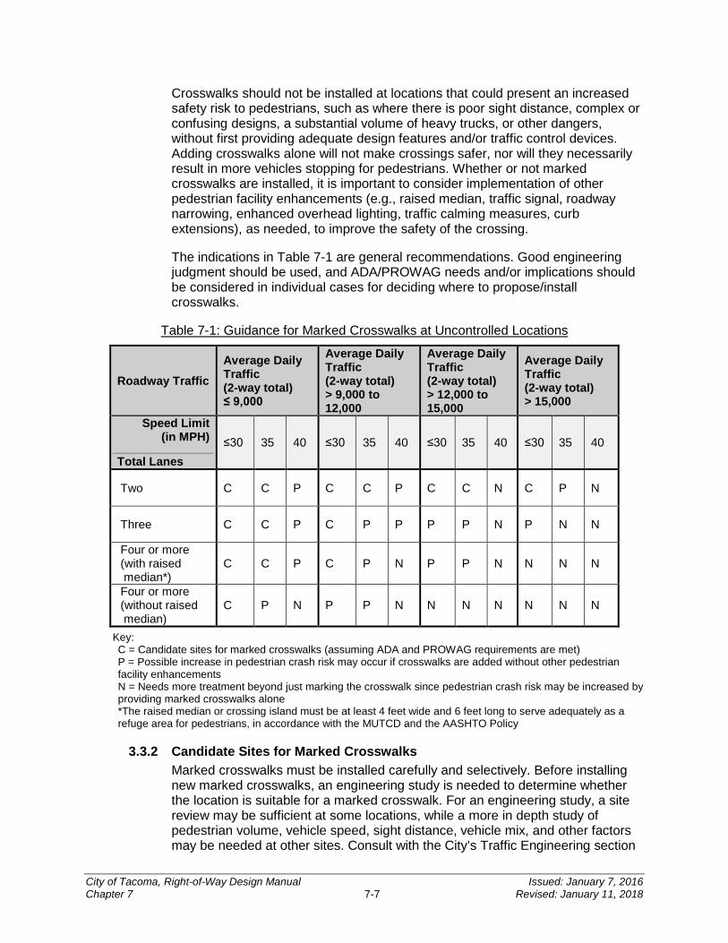
Crosswalks should not be installed at locations that could present an increased safety risk to pedestrians, such as where there is poor sight distance, complex or confusing designs, a substantial volume of heavy trucks, or other dangers, without first providing adequate design features and/or traffic control devices. Adding crosswalks alone will not make crossings safer, nor will they necessarily result in more vehicles stopping for pedestrians. Whether or not marked crosswalks are installed, it is important to consider implementation of other pedestrian facility enhancements (e.g., raised median, traffic signal, roadway narrowing, enhanced overhead lighting, traffic calming measures, curb extensions), as needed, to improve the safety of the crossing.
The indications in Table 7-1 are general recommendations. Good engineering judgment should be used, and ADA/PROWAG needs and/or implications should be considered in individual cases for deciding where to propose/install crosswalks.
Table 7-1: Guidance for Marked Crosswalks at Uncontrolled Locations
Roadway Traffic Average Daily Traffic (2-way total) ≤ 9,000
Average Daily Traffic (2-way total) > 9,000 to 12,000
Average Daily Traffic (2-way total) > 12,000 to 15,000
Average Daily Traffic (2-way total) > 15,000
Speed Limit (in MPH)
___________________ Total Lanes
≤30 35 40 ≤30 35 40 ≤30 35 40 ≤30 35 40
Two C C P C C P C C N C P N
Three C C P C P P P P N P N N
Four or more (with raised median*)
C C P C P N P P N N N N
Four or more (without raised median)
C P N P P N N N N N N N
Key: C = Candidate sites for marked crosswalks (assuming ADA and PROWAG requirements are met) P = Possible increase in pedestrian crash risk may occur if crosswalks are added without other pedestrian facility enhancements N = Needs more treatment beyond just marking the crosswalk since pedestrian crash risk may be increased by providing marked crosswalks alone *The raised median or crossing island must be at least 4 feet wide and 6 feet long to serve adequately as a refuge area for pedestrians, in accordance with the MUTCD and the AASHTO Policy
3.3.2 Candidate Sites for Marked Crosswalks Marked crosswalks must be installed carefully and selectively. Before installing new marked crosswalks, an engineering study is needed to determine whether the location is suitable for a marked crosswalk. For an engineering study, a site review may be sufficient at some locations, while a more in depth study of pedestrian volume, vehicle speed, sight distance, vehicle mix, and other factors may be needed at other sites. Consult with the City’s Traffic Engineering section
City of Tacoma, Right-of-Way Design Manual Issued: January 7, 2016 Chapter 7 7-7 Revised: January 11, 2018
to determine what is applicable. It is recommended that a minimum utilization of 20 pedestrian crossings per peak hour (or 15 or more elderly and/or child pedestrians) be confirmed at a location before placing a high priority on the installation of a marked crosswalk alone.
In some situations (e.g., low-speed, two-lane streets in downtown areas), installing a marked crosswalk may help consolidate multiple crossing points. Engineering judgment should be used to install crosswalks at preferred crossing locations (e.g., at a crossing location at a streetlight as opposed to an unlit crossing point nearby). While overuse of marked crossings at uncontrolled locations should be avoided, higher priority should be placed on providing crosswalk markings where pedestrian volume exceeds the threshold mentioned above. Marked crosswalks and other pedestrian facilities (or lack of facilities) should be routinely monitored to determine what improvements are needed.
Certain locations have the potential for the pedestrian crash risk to increase if a crosswalk(s) is added without other pedestrian facility enhancements. These locations should be closely monitored and enhanced with other pedestrian crossing improvements, if necessary, before adding a marked crosswalk.
3.3.3 Additional Treatments at Crosswalks Marked crosswalks alone are typically insufficient, since pedestrian crash risk may be increased by providing only marked crosswalks at some locations. Consider using other treatments, such as traffic calming treatments, traffic signals with pedestrian signals where warranted, or other substantial crossing improvement to improve crossing safety for pedestrians. See applicable scenarios in Table 7-1.
SECTION 4 Construction Requirements
As dictated by the design, the installation of channelization and/or signing shall be in accordance with Sections 8-21 and 8-22 of WSDOT Standard Specifications; City Standard Plans; City of Tacoma Channelization and Signing General Notes (Attachments 7-1 and 7-2); and the MUTCD.
All pavement markings in work areas where new channelization transitions into or replaces existing channelization shall be removed. Removal of channelization elements shall be required as specified in Section 8-22.3(6) of the WSDOT Standard Specifications or in accordance with the project specifications.
When work is performed in the roadway, traffic control devices shall be installed to warn and protect motorists, bicyclists, and pedestrians at all times. The City requires that all flagging, signs and all other traffic control devices conform to Section 1-07.23 and 1-10 of the WSDOT Standard Specifications as supplemented or amended by the Washington State Chapter of APWA. Construction traffic control shall also conform to the current edition of the MUTCD, Part 6 and the City’s Traffic Control Handbook.
A pre-construction meeting with City staff will be required prior to installing any signs, sign posts, or pavement markings within the ROW (see CHAPTER 2).
City of Tacoma, Right-of-Way Design Manual Issued: January 7, 2016 Chapter 7 7-8 Revised: January 11, 2018
SECTION 5 Non-Essential Signs
5.1 Description Destination/wayfinding signs, cultural interest signs, memorial signs, and other similar signs are supplemental to other signing and shall not be installed where there is insufficient spacing from signing of higher priority. These signs are not required for the safety and operation of the public transportation network. Costs related to the purchase, installation, and maintenance of these signs will be borne by the party requesting the sign. While no maintenance agreement is typically necessary, the signs will typically only be maintained by the City when requests are submitted for consideration by the City’s Traffic Engineering Section. Advertising and private signs are not addressed herein, but instead are controlled by applicable City ordinances and state and federal regulations.
5.2 Historical and Honorary Street Names Tacoma Resolution No. 38091, revising the City’s Policy on Place Names and Name Changes, describes the process by which the City Council adopts historical and honorary street names. Such names are not used for addressing purposes, will be secondary to the sign which is used for addressing purposes, and will have an appearance and location consistent with the requirements and recommendations found in WAC-468-95 pertaining to the Uniform Traffic Control Devices for Streets and Highways Manual.
5.3 Private Street Name Signs The construction of private street name signs shall follow the City’s standards (contact the City’s Traffic Engineering Section). Review of private street names shall follow the same process as for public street name signs in order to ensure proper review for addressing and emergency response purposes. Naming of streets shall adhere with the following and shall consist of three components:
1. Direction Prefix or Suffix • The street name prefix shall consist of “N,” “S,” or “E” according to the following:
“N” – All streets north of Division Avenue/6th Avenue between Commencement Bay and Tacoma Narrows
“S” – All streets south of Division Avenue and west of ‘A’ Street except for those areas included under west end streets
“E” – All streets between ‘A’ Street and Marine View Drive
• The street name suffix shall consist of “W” or “NE” according to the following:
“W” – All streets south of South 19th Street and west of Orchard Street “NE” – All streets east of Marine View Drive
2. Street Name • Shall confirm to existing grid system
• Shall not duplicate or be similar to any other street names, unless conforming to the above or unless it is a numerical street name
• Shall not result in any duplicate intersections
City of Tacoma, Right-of-Way Design Manual Issued: January 7, 2016 Chapter 7 7-9 Revised: January 11, 2018
3. Street Type • “Avenue”
May only be used for north/south oriented streets When streets are skewed from actual north/south, shall only be used when
parallel streets are of the same type
• “Street”
May be used for north/south or east/west oriented streets May not be used for north/south numbered streets When streets are skewed from actual north/south or east/west, shall only be
used when parallel streets are of the same type
• “Drive,” “Blvd,” “Way,” “Lane,” “Road,” and “Place”
May only be used for meandering streets which cannot conform to “Avenue” or “Street” criteria shown above
• “Court”
May only be used in conjunction with “Street” or “Avenue” where alignment is slightly offset from the street or avenue
• “Terrace,” “Circle,” and “Loop”
Not allowed
5.4 Temporary Signs Political signs and other temporary signs placed within the ROW are allowed according to the provisions of the TMC (see TMC 2.05.275 for information about Political Signs). Other temporary signs not explicitly addressed by the TMC are not permitted within the ROW.
5.5 Adopt-a-Spot, Adopt-a-Roadway, and Memorial Signs Roadside memorials are not permitted on City streets. However, citizens participating in the adopt-a-spot program may recognize people on the recognition sign installed with the adopt-a-spot sign.
Adopt-a-spot and adopt-a-roadway signs are allowed at locations participating in the litter reduction program administered by Neighborhood and Community Services Department.
When the City Council adopts an act or resolution memorializing or dedicating a highway, bridge, or other highway component, the associated memorial or dedication signs shall meet the requirements of Section 2M.10 of the MUTCD.
5.6 Gateway and Neighborhood Signs Neighborhood gateway signage plans are permitted on a case-by-case basis in consultation with the City’s Traffic Engineering Section.
City of Tacoma, Right-of-Way Design Manual Issued: January 7, 2016 Chapter 7 7-10 Revised: January 11, 2018
5.7 Wayfinding, Guide, and Cultural and Recreational Interest Signs Signs relating to services and businesses are not typically provided in urban areas, and are not permitted. All other wayfinding, guide, and cultural/recreational interest signs shall meet the requirements of this section and the MUTCD.
5.7.1 Recreational and Cultural Interest Signs Recreational and cultural interest signs shall meet the requirements of this section and of Section 2M.02 of the MUTCD.
Signs for recreational/cultural interest destinations shall be located in advance of the closest intersection that provides the most direct and best route to the destination. Normally, a sign at the cross street is all that is necessary to provide direction to the destination that may be reached from the intersection. For most locations, the sign may not be located farther than 1 mile from the destination. Destinations which may be considered for recreational and cultural interest signing include:
• Recreational
State and national parks and recreation areas Marinas Regional recreational facilities/areas Public golf courses (symbol sign only)
• Cultural Interest
National historic sites and landmarks Museums of regional significance Civic centers
5.7.2 Destination Guide Signs Destination guide signs are governed by Section 2D.37 of the MUTCD.
These signs, which use white borders, text, and legends on a green background, are installed on major roadways to provide direction to major traffic generators and major roadways. Destinations which may be considered for destination guide signing include:
• College or university: a resident campus of a degree-granting accredited institution.
• Arena: a stadium, sports complex, auditorium, civic center, amphitheater or racetrack. The facility must have at least 50,000 visitors annually and 5,000 seats.
• Convention center: a center for hosting events with annual attendance of at least 50,000 and a seating capacity of at least 5,000 seats.
• Multimodal transportation facility: ferry terminals; fixed route stations providing onsite ticketing or access to interstate rail service; off-street transit center serving at least 5 routes; or facilities with over 100,000 annual boardings.
City of Tacoma, Right-of-Way Design Manual Issued: January 7, 2016 Chapter 7 7-11 Revised: January 11, 2018
• Park and ride: government owned and operated facilities providing service to carpool, vanpool, or other transit service.
5.7.3 Community Wayfinding Signs Community wayfinding signs are addressed in Section 2D.50 of the MUTCD.
Destinations may include those destinations allowed under the destination guide and recreational and cultural interest sub-sections above, as well as those excluded from other categories, such as parks and neighborhood centers. Destinations which may be considered for community wayfinding signing include:
• Business districts
• Commercial districts
• Public museums
• Performing arts centers
• Community centers
Within business districts, community wayfinding signs are installed based on recommendations from local stakeholders and the City’s Transportation Commission (or their designated sub-committee), see Transportation Commission website.
5.7.4 Non-motorized Wayfinding Signs Non-motorized wayfinding signs are permitted, but may not be retroreflective, and may not be placed in such a manner that they would appear to be directed at automobile traffic.
5.7.5 Destinations Excluded from Signing Unless explicitly allowed in one of the sign categories above, signs may not include the following destinations:
• Parks, zoos, water parks, golf courses, and fairgrounds
• Historical homes, viewpoints, buildings, or sites
• Churches, religious sites, cemeteries, neighborhood centers, neighborhood parks, libraries, clubs, schools, and similar locations
• Shopping centers, private businesses, privately-owned museums, and theaters
City of Tacoma, Right-of-Way Design Manual Issued: January 7, 2016 Chapter 7 7-12 Revised: January 11, 2018

Attachment 7-1: City of Tacoma Channelization General Notes
The following general notes shall appear within the sheets comprising the channelization plans. Additional notes shall be added by the traffic designer as necessary to properly clarify the intent of the design.
1. The City of Tacoma Traffic Engineering section shall be notified at least three (3) business days prior to starting any striping work.
2. Unless otherwise specified, all pavement marking installations and removals shall conform to the requirements set forth in the City’s specifications. Items not covered under the City specifications shall conform to the WSDOT/APWA Standard Specifications and the most recent edition of the Manual on Uniform Traffic Control Devices (MUTCD) as adopted and modified by Washington Administrative Code (WAC) 468-95.
3. Temporary traffic control shall conform to the most recent edition of the City of Tacoma Traffic Control Handbook, the MUTCD, and/or as directed by the City of Tacoma.
4. The Contractor shall be responsible for the layout and installation of the permanent pavement markings. Pavement marking dimensions are to the center of the stripe for single-line striping and to the center of the gap between the two lines for double-line striping. Where curb and gutter are present, dimensions are to the face of curb, or to the edge of pavement absent curb and gutter. The Contractor shall schedule inspection of the pavement marking layout at least three (3) business days prior to the installation of the permanent pavement marking. Inspection shall take place during daytime and on a business day prior to installation of permanent pavement markings. Any permanent pavement markings applied prior to field inspection by the Traffic Engineering section shall be removed and re-striped at the Contractor’s expense.
5. The Contractor shall follow all dimensions, notes, details, and standards when installing pavement striping, markings, and markers. The channelization plans may be modified as directed by the City Traffic Engineer. The Contractor shall refer any questions concerning pavement markings to the Traffic Engineering section via the City’s Construction Inspector for the project.
6. Generally, raised pavement markers (RPMs) shall be installed in conjunction with striping efforts and in accordance with City of Tacoma Standard Plans. Exceptions are possible; coordinate with the City’s Traffic Engineering Section. All markers shall be installed so that the reflective face of each marker is facing the direction of approaching traffic and is perpendicular to the direction of traffic flow.
7. The Contractor shall remove all existing pavement markings and striping in conflict with the final striping plan by hydro-blasting or other approved noninvasive method. All removal methods shall be done in conformance with WSDOT/APWA Standard Specifications. If the removal damages the underlying pavement as described in the WSDOT/APWA Standard Specifications, then the pavement shall be restored to a state equaling or exceeding its previous state. If the obliteration causes shadowing (or “ghost” markings), or in the opinion of the City Traffic Engineer will cause confusion to drivers, the Contractor shall remedy through an approved means and method. Applying additional markings to obscure erroneous markings is not an approved method for obliteration. Striping obliteration may need to exceed the
City of Tacoma, Right-of-Way Design Manual Issued: January 7, 2016 Chapter 7 7-13 Revised: January 11, 2018
project limits so that the new striping will match permanent existing pavement markings.
8. The Contractor shall clean the roadway surface to the satisfaction of the City by power broom, street sweeping, air jet blowing, and/or water jet/truck prior to the placement of all pavement markings unless directed otherwise. The road pavement surface conditions, including any pavement curing times, shall be in accordance with the WSDOT/APWA Standard Specifications prior to the application of permanent pavement markings.
9. Permanent pavement markings should be fully implemented before allowing public use of the roadway. Temporary pavement markings controlling traffic as intended by the permanent channelization plans may be permissible in the case where pavement conditions/materials preclude implementation of the permanent pavement markings until a later time. Temporary markings shall not be used any longer than necessary and no longer than one (1) month unless otherwise approved or mitigated, which may include a re-application of the temporary markings.
City of Tacoma, Right-of-Way Design Manual Issued: January 7, 2016 Chapter 7 7-14 Revised: January 11, 2018
Attachment 7-2: City of Tacoma Signing General Notes
The following general notes shall appear within the sheets comprising the signing plans. Additional notes shall be added by the traffic designer as necessary to properly clarify the intent of the design.
1. The City of Tacoma Traffic Engineering Section shall be notified at least three (3) business days prior to starting any signing work.
2. Temporary traffic control shall conform to the most recent edition of the City of Tacoma Traffic Control Handbook, the MUTCD, and/or as directed by the City of Tacoma.
3. All signs shall conform to the MUTCD with respect to colors, shape, size, content, retroreflectivity, and placement relative to the roadway. All sign panels shall be 0.080-inch thick aluminum (non-recycled) with prismatic sheeting (Type IV or better, or as specified). Sign posts shall be 2-inch square perforated galvanized steel tubing per City Standard Plans, unless otherwise specified.
4. The Contractor shall submit all sign formats/layouts (with dimensions) to the City’s Traffic Engineering Section for approval prior to fabrication.
5. Any traffic signs, including street name signs, which are in close proximity to an existing or proposed street light pole (confer with Traffic Engineering in advance for approval), shall be properly mounted to the pole instead of installing a new sign post. Any added expense relating to a need for different mounting hardware and/or equipment shall be the Contractor’s responsibility. Prior to installation, sign locations and offsets may be adjusted by the City to improve visibility or safety.
6. Any existing signs that need to be removed as a result of construction, or due to conflict with installed signs, shall be done so by the Contractor at their expense. These signs shall be removed, protected, and stored for possible reinstallation by the Contractor or for salvaging and returning to the City. Signs damaged during construction shall be replaced at the Contractor’s expense.
7. The Contractor shall ensure that at no time a traffic sign is installed in such a way as to be blocked by trees or vegetation, either existing or pending. All sign locations shall not interfere with pedestrian movement as defined by the Americans with Disabilities Act (ADA) and/or Public Rights-of-Way Accessibility Guidelines (PROWAG). In both of these cases, the Contractor shall contact the Traffic Engineering section to provide an alternate location for the installation of the sign(s) in question.
8. Temporary signs installed for construction purposes shall be to be mounted in the least intrusive locations and manner as possible to minimize damage to sidewalks or blocking of other signs/traffic control devices. Use of existing sign posts and street light poles is preferred. Any damage to City infrastructure caused by temporary sign installations shall be restored upon removal of the temporary sign/post.
City of Tacoma, Right-of-Way Design Manual Issued: January 7, 2016 Chapter 7 7-15 Revised: January 11, 2018
CHAPTER 8Pedestrian Facilities
INTRODUCTION ..................................................................................... 8-3
SECTION 1 Design Guides and Resources ..................................... 8-3 1.1 Federal/State/Local Laws and Codes .......................................................................8-3 1.2 Design Guidance ......................................................................................................8-4 1.3 Supporting Information .............................................................................................8-4
SECTION 2 Policy .............................................................................. 8-5
SECTION 3 ADA Requirements by Project Type ............................. 8-5 3.1 New Construction Projects........................................................................................8-5 3.2 Alteration Projects ....................................................................................................8-5
3.2.1 Maximum Extent Feasible Justification ................................................................ 8-7
SECTION 4 Pedestrian Circulation Paths (PCPs) ........................... 8-7 4.1 Accessibility Criteria for Pedestrian Circulation Paths ...............................................8-8
4.1.1 Vertical Clearance ............................................................................................... 8-8 4.1.2 Horizontal Encroachment ..................................................................................... 8-8 4.1.3 Post-Mounted Objects ......................................................................................... 8-8
SECTION 5 Pedestrian Access Routes ............................................ 8-9 5.1 Accessibility Criteria for Pedestrian Access Routes ................................................ 8-10
5.1.1 Clear Width ........................................................................................................ 8-10 5.1.2 Cross Slope and Grade ..................................................................................... 8-10 5.1.3 Surface .............................................................................................................. 8-11 5.1.4 Horizontal Openings .......................................................................................... 8-11
SECTION 6 Sidewalks ..................................................................... 8-12 6.1 Sidewalk and Buffer Widths .................................................................................... 8-12 6.2 Sidewalks at Driveways .......................................................................................... 8-12
SECTION 7 Curb Ramps ................................................................. 8-13 7.1 Types of Curb Ramps ............................................................................................. 8-13
7.1.1 Perpendicular Curb Ramp ................................................................................. 8-13 7.1.2 Parallel Curb Ramp ........................................................................................... 8-14 7.1.3 Combination Curb Ramp ................................................................................... 8-15
7.2 Accessibility Criteria for Curb Ramps ...................................................................... 8-16 7.2.1 Clear Width ........................................................................................................ 8-16 7.2.2 Running Slope ................................................................................................... 8-16 7.2.3 Cross Slope ....................................................................................................... 8-16 7.2.4 Landing .............................................................................................................. 8-16 7.2.5 Flares and Pedestrian Curbing .......................................................................... 8-17
8
City of Tacoma, Right-of-Way Design Manual Issued: January 7, 2016 Chapter 8 8-1 Revised: January 11, 2018
7.2.6 Counter Slope .................................................................................................... 8-17 7.2.7 Detectable Warning Surfaces ............................................................................ 8-17 7.2.8 Surfaces ............................................................................................................ 8-17 7.2.9 Grade Breaks .................................................................................................... 8-17 7.2.10 Clear Space ................................................................................................... 8-17
7.3 Curb Ramp Drainage .............................................................................................. 8-17
SECTION 8 Crosswalks .................................................................. 8-18 8.1 Designing Crossing Facilities .................................................................................. 8-18 8.2 Crosswalks at Intersections .................................................................................... 8-19
8.2.1 Unmarked Crossings ......................................................................................... 8-19 8.2.2 Marked Crossings .............................................................................................. 8-19 8.2.3 Closed Crossings ............................................................................................... 8-20
8.3 Midblock Crosswalks .............................................................................................. 8-20 8.4 Sight Distance at Crosswalks ................................................................................. 8-20 8.5 Curb Extensions ..................................................................................................... 8-21
SECTION 9 Raised Medians/Traffic Islands .................................. 8-22 9.1 Accessibility Criteria for Raised Medians and Traffic Islands .................................. 8-23
SECTION 10 Pedestrian Pushbuttons at Signals ............................ 8-24 10.1 Accessibility Criteria for All Pedestrian Pushbuttons ............................................... 8-25
10.1.1 Location Requirements .................................................................................. 8-25 10.1.2 Clear Space Requirements ............................................................................ 8-25 10.1.3 Reach Range Requirements .......................................................................... 8-25
10.2 Accessibility Criteria for APS .................................................................................. 8-26
SECTION 11 On-Street Parking ........................................................ 8-27
SECTION 12 At-Grade Railroad Crossings ...................................... 8-27
SECTION 13 Pedestrian Grade Separations .................................... 8-28
SECTION 14 Other Pedestrian Facilities ......................................... 8-29 14.1 Transit Stops and School Bus Stops ....................................................................... 8-29 14.2 Access Ramps ........................................................................................................ 8-31
14.2.1 Accessibility Criteria for Access Ramps ......................................................... 8-31 14.3 Guards and Handrails for Pedestrian Facilities ....................................................... 8-32
14.3.1 Fall Protection Guards ................................................................................... 8-32 14.3.2 Accessible Fall Protection Railing .................................................................. 8-32 14.3.3 Accessible Handrail ....................................................................................... 8-32 14.3.4 Accessibility Criteria for Handrail .................................................................... 8-33
14.4 Other Pedestrian Facilities, Features, and Elements .............................................. 8-34
SECTION 15 Illumination and Signing ............................................. 8-34
SECTION 16 Work Zone Pedestrian Accommodation .................... 8-34
City of Tacoma, Right-of-Way Design Manual Issued: January 7, 2016 Chapter 8 8-2 Revised: January 11, 2018
INTRODUCTION
The City strives to ensure that the ROW is usable and accessible for everyone. One common mode of transportation is pedestrian travel. It is used at some point by nearly everyone and is a critical link to everyday life for many. Designers must be aware of the various physical needs and abilities of pedestrians in order to ensure facilities provide universal access.
Section 504 of the Rehabilitation Act and the ADA require pedestrian facilities to be designed and constructed to be readily accessible to and usable by persons with disabilities. This chapter provides accessibility criteria for the design of pedestrian facilities that meet applicable local, state, and federal standards.
The pedestrian facilities included in a project are determined during the planning phase based on the 6 year Transportation Plan, the Transportation Master Plan, the Curb Ramp Installation Matrix, Right-of-Way Restoration Policy, and other applicable City plans and ordinances.
When developing pedestrian facilities in locations with challenging grades or a limited amount of ROW, designers may face multiple challenges. It is important that designers become familiar with the ADA accessibility criteria in order to appropriately balance intersection design with the often competing needs of pedestrians and other roadway users.
Similar to the roadway infrastructure, pedestrian facilities (and elements) require periodic maintenance in order to prolong the life of the facility and provide continued usability. Title II of the ADA requires that all necessary features be accessible and maintained in operable working condition for use by individuals with disabilities.
SECTION 1 Design Guides and Resources
The following resources are meant to accompany the requirements of this Manual:
1.1 Federal/State/Local Laws and Codes • ADA, 28 Code of Federal Regulations (CFR) Part 35
• 23 CFR Part 652, Pedestrians and Bicycle Accommodations and Projects
• 49 CFR Part 27, Nondiscrimination on the Basis of Disability in Programs or Activities Receiving Federal Financial Assistance (Section 504 of the Rehabilitation Act of 1973 implementing regulations)
• Revised Code of Washington (RCW) 35.68, Sidewalks, Gutters, Curbs and Driveways
• RCW 35.68.075, Curb Ramps for persons with Disabilities
• RCW 46.04.160, Crosswalk (definition)
• RCW 46.61, Rules of the Road
• RCW 47.24.020, City Streets as Part of State Highways – Jurisdiction, Control
• PROWAG
• City of Tacoma Curb Ramp Installation Matrix
• City of Tacoma Right-of-Way Restoration Policy
City of Tacoma, Right-of-Way Design Manual Issued: January 7, 2016 Chapter 8 8-3 Revised: January 11, 2018
• City of Tacoma Transportation Master Plan
• SWMM
• City of Tacoma Complete Streets Guidelines
• City of Tacoma APS Policy
• TMC
1.2 Design Guidance • For buildings and onsite facilities; applies to new construction or alterations: ADA
Standards for Accessible Design, U.S. Department of Justice
• For transit, light rail, and similar public transportation facilities: ADA Standards for Transportation Facilities
• U.S. Department of Justice/Department of Transportation Joint Technical Assistance on the Title II of the ADA Requirements to Provide Curb Ramps when Streets, Roads, or Highways are Altered through Resurfacing
• MUTCD, USDOT, FHWA; as adopted and modified by Chapter 468-95 WAC
• Revised Guidelines for Accessible Public Rights-of-Way. The current best practices for evaluation and design of pedestrian facilities in the public ROW per the following FHWA Memoranda: Bicycle and Pedestrian Program and ADA/Section 504
• City of Tacoma Standard Plans
1.3 Supporting Information • AASHTO’s A Policy on Geometric Design of Highways and Streets (Green Book)
• WSDOT’s Field Guide for Accessible Public Rights of Way
• AASHTO’s Guide for the Planning, Design, and Operation of Pedestrian Facilities provides guidance on the planning, design, and operation of pedestrian facilities along streets and highways. Specifically, the guide focuses on identifying effective measures for accommodating pedestrians on public ROW.
• Pedestrian Facilities Guidebook: Incorporating Pedestrians into Washington’s Transportation System
• FHWA’s Pedestrian Facilities Users Guide – Providing Safety and Mobility provides useful information regarding walkable environments, pedestrian crashes and their countermeasures, and engineering improvements for pedestrians
• Proposed Accessibility Guidelines for Pedestrian Facilities in the Public Right-of-Way, July 26, 2011, U.S. Access Board. Federal Notice of Proposed Rule Making that gives a preview of potential future revisions to the PROWAG
• “Special Report: Accessible Public Rights-of-Way – Planning & Design for Alterations,” Public Rights-of-Way Access Advisory Committee, July 2007
• WSDOT’s Understanding Flexibility in Transportation Design – Washington
• Washington State Bicycle Facilities and Pedestrian Walkways Plan
City of Tacoma, Right-of-Way Design Manual Issued: January 7, 2016 Chapter 8 8-4 Revised: January 11, 2018
SECTION 2 Policy
It is the City’s policy to provide appropriate pedestrian facilities as an integral part of the transportation system, and that bicycle and pedestrian facilities are given full consideration in the planning and design of new construction and reconstruction ROW projects, except where bicycle and pedestrian use is prohibited.
SECTION 3 ADA Requirements by Project Type
Wherever pedestrian facilities are intended to be a part of the transportation facility, federal regulations (28 CFR Part 35) require that those pedestrian facilities meet ADA guidelines. All new construction or alteration of existing transportation facilities must be designed and constructed to be accessible to and usable by persons with disabilities. FHWA is one of the federal agencies designated by the U.S. Department of Justice to ensure compliance with the ADA for transportation projects.
3.1 New Construction Projects New construction projects including the construction of a new roadway, intersection, or other new transportation facility shall address and include pedestrians’ needs in the project. All pedestrian facilities included in these projects must fully meet the ADA and City accessibility criteria when built.
3.2 Alteration Projects Any project that affects or could affect the usability of a pedestrian facility is classified as an alteration project. Alteration projects include, but are not limited to, renovation; rehabilitation; reconstruction; historic restoration; resurfacing of circulation paths or vehicular ways; and changes or rearrangement of structural parts or elements of a facility. Where existing elements or spaces are altered, each altered element or space within the limits of the project shall comply with the applicable ADA and City accessibility requirements to the maximum extent feasible.
The following are some examples of project types that are classified as alteration projects and can potentially trigger a variety of ADA requirements:
• HMA overlay or inlay
• Traffic signal installation or retrofit
• Roadway widening
• Realignment of a roadway (vertical or horizontal)
• Sidewalk improvements
• Portland cement concrete panel repair/replacement
• Bridge replacement
• Raised channelization
The following are not considered alterations:
• Spot pavement repair
City of Tacoma, Right-of-Way Design Manual Issued: January 7, 2016 Chapter 8 8-5 Revised: January 11, 2018
• Liquid-asphalt sealing, chip seal, or crack sealing
• Lane or crosswalk restriping
If there is uncertainty as to whether a project meets the definition of an alteration project, consult with the City’s ADA Coordinator at (253) 591-5785.
The following apply to alteration projects:
• All new pedestrian facilities included in an alteration project that are put in place within an existing developed ROW must meet applicable ADA and City accessibility requirements to the maximum extent feasible.
• All existing pedestrian facilities disturbed by construction of an alteration project must be replaced. The replacement facilities must meet applicable ADA and City accessibility requirements to the maximum extent feasible.
• An alteration project shall not decrease or have the effect of decreasing the accessibility of a pedestrian facility or an accessible connection to an adjacent building or site.
• Within the construction impact zone of an alteration project, any existing connection from a PAR to a crosswalk (marked or unmarked) that is missing a required curb ramp must have a curb ramp installed that meets applicable accessibility requirements to the maximum extent feasible. Refer to the City of Tacoma Curb Ramp Installation Matrix to determine which work requires the construction of curb ramps. The City of Tacoma Curb Ramp Installation Matrix is available on the govME website.
• A crosswalk served by a curb ramp must also have an existing curb ramp in place on the receiving end unless there is no curb or sidewalk on that end of the crosswalk (see RCW 35.68.075). If there is no existing curb ramp in place on the receiving end, or the existing curb ramp does not meet the Existing Curb Ramp Evaluation Criteria found in the City of Tacoma Curb Ramp Installation Matrix, an accessible curb ramp must be provided. This requirement must be met regardless of whether the receiving end of the crosswalk is located within the project scope of work.
• Evaluate all existing curb ramps within the construction impact zone of an alteration project to determine whether curb ramp design elements meet the accessibility criteria (see City of Tacoma Curb Ramp Installation Matrix, Existing Curb Ramp Evaluation Criteria). Modify existing curb ramps that do not meet the ADA and City accessibility criteria. This may also trigger modification of other adjacent pedestrian facilities to incorporate transitional segments in order to ensure specific elements of a curb ramp will meet the accessibility criteria.
• Evaluate all existing marked and unmarked crosswalks within the construction impact zone of an alteration project that includes HMA overlay (or inlay) of an existing roadway and does not include reconstruction, realignment, or widening of the roadway for crosswalk accessibility criteria (see Section 8.2 of this chapter). If it is not possible to meet the applicable ADA and City accessibility requirements for crosswalks, document this in a maximum extent feasible (MEF) justification and attach it to the final plan set (see Section 3.2.1 of this chapter).
City of Tacoma, Right-of-Way Design Manual Issued: January 7, 2016 Chapter 8 8-6 Revised: January 11, 2018
• Within the construction impact zone of an alteration project that includes reconstruction, realignment, or widening of the roadway, evaluate all existing crosswalks (marked or unmarked) to determine whether crosswalk design elements meet the accessibility criteria (see Section 8.2 of this chapter). Modify crosswalk slopes to meet the applicable ADA and City accessibility requirements.
3.2.1 Maximum Extent Feasible Justification It may not always be possible to fully meet the applicable ADA and City accessibility requirements during alterations of existing facilities. If such a situation is encountered, consult with the City’s ADA Coordinator to develop a workable solution to meet the accessibility requirements, and/or draft a MEF justification. Cost is not to be used as a justification for not meeting the accessibility criteria. Physical terrain or site conditions that would require structural impacts, environmental impacts, or unacceptable impacts to the community in order to achieve full compliance with the accessibility criteria are some of the factors that can be used to determine if the MEF has been met. If site conditions are determined to be ‘virtually impossible’ (per PROWAG definition and case law) to meet the accessibility criteria for an element, then document the decision in one of the following two ways (the documentation method will depend on the complexity and length of the justification):
• Depending on the noncompliant elements that warrant a short explanation (e.g., curb ramp flare slope on the uphill side) the MEF can be contained within a text box and a leader line extended to the non-compliant element as part of the plan set. The MEF must include the following:
A description of the scope of work; The site specific factors affecting compliance; and The measures implemented to improve compliance.
• More complicated issues such as non-compliant cross slopes of crosswalks or curb ramps may require a MEF memorandum. All MEF memorandums should be reviewed and approved by the City’s ADA Coordinator, City Engineer or designee.
SECTION 4 Pedestrian Circulation Paths
Pedestrian circulation paths (PCPs) are prepared exterior or interior ways of passage provided for pedestrian travel. They include independent walkways, sidewalks, shared-use paths, and other types of pedestrian facilities. PCPs can either be immediately adjacent to streets or separated from streets by a buffer. Examples of PCPs are shown below.
Provide smooth finish to vertical surfaces (see Section 5.1.3 of this chapter) adjacent to a PCP to mitigate potential snagging or abrasive injuries from accidental contact with the surface. Any projections into the PCP must be cane detectable or extend 4 inches or less into the path (see Section 4.1.2 of this chapter).
When relocation of utility poles, signage, and other fixtures is necessary for a project, determine the impact of their new location on all PCPs. Look for opportunities to relocate obstructions, such as existing utility objects, away from the PCP.
City of Tacoma, Right-of-Way Design Manual Issued: January 7, 2016 Chapter 8 8-7 Revised: January 11, 2018
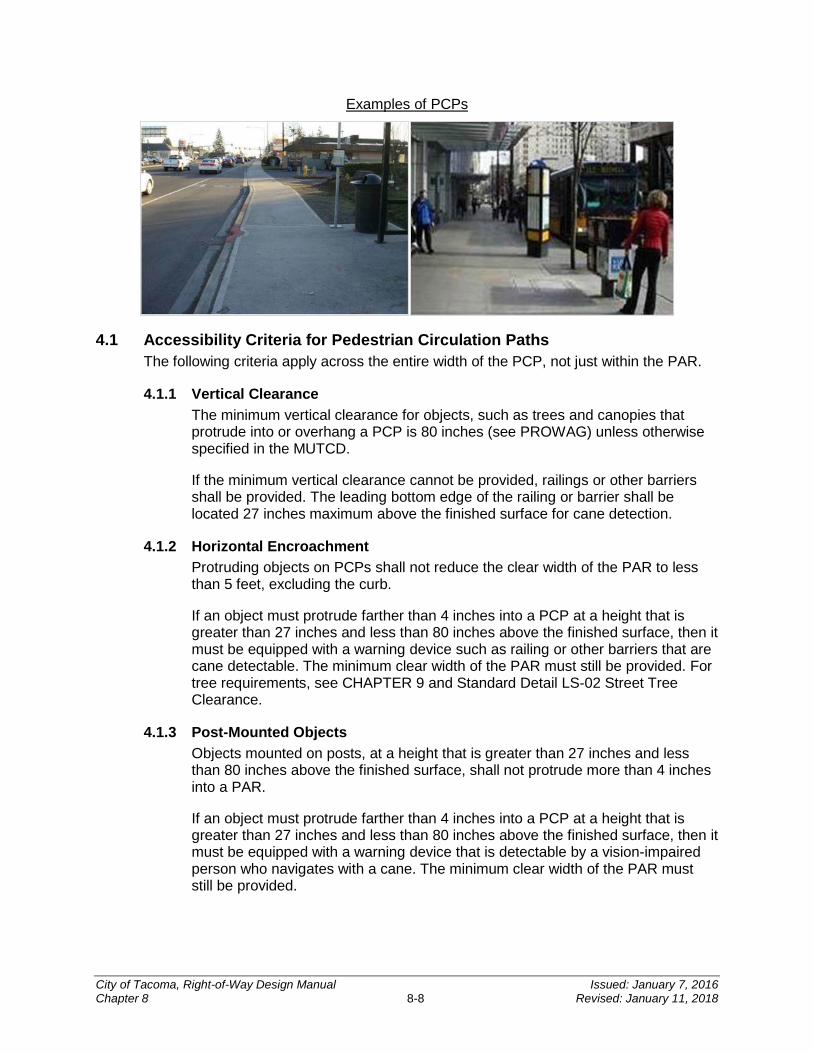
Examples of PCPs
4.1 Accessibility Criteria for Pedestrian Circulation Paths The following criteria apply across the entire width of the PCP, not just within the PAR.
4.1.1 Vertical Clearance The minimum vertical clearance for objects, such as trees and canopies that protrude into or overhang a PCP is 80 inches (see PROWAG) unless otherwise specified in the MUTCD.
If the minimum vertical clearance cannot be provided, railings or other barriers shall be provided. The leading bottom edge of the railing or barrier shall be located 27 inches maximum above the finished surface for cane detection.
4.1.2 Horizontal Encroachment Protruding objects on PCPs shall not reduce the clear width of the PAR to less than 5 feet, excluding the curb.
If an object must protrude farther than 4 inches into a PCP at a height that is greater than 27 inches and less than 80 inches above the finished surface, then it must be equipped with a warning device such as railing or other barriers that are cane detectable. The minimum clear width of the PAR must still be provided. For tree requirements, see CHAPTER 9 and Standard Detail LS-02 Street Tree Clearance.
4.1.3 Post-Mounted Objects Objects mounted on posts, at a height that is greater than 27 inches and less than 80 inches above the finished surface, shall not protrude more than 4 inches into a PAR.
If an object must protrude farther than 4 inches into a PCP at a height that is greater than 27 inches and less than 80 inches above the finished surface, then it must be equipped with a warning device that is detectable by a vision-impaired person who navigates with a cane. The minimum clear width of the PAR must still be provided.
City of Tacoma, Right-of-Way Design Manual Issued: January 7, 2016 Chapter 8 8-8 Revised: January 11, 2018
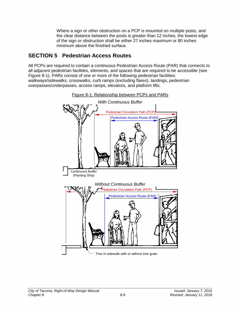
Where a sign or other obstruction on a PCP is mounted on multiple posts, and the clear distance between the posts is greater than 12 inches, the lowest edge of the sign or obstruction shall be either 27 inches maximum or 80 inches minimum above the finished surface.
SECTION 5 Pedestrian Access Routes
All PCPs are required to contain a continuous Pedestrian Access Route (PAR) that connects to all adjacent pedestrian facilities, elements, and spaces that are required to be accessible (see Figure 8-1). PARs consist of one or more of the following pedestrian facilities: walkways/sidewalks, crosswalks, curb ramps (excluding flares), landings, pedestrian overpasses/underpasses, access ramps, elevators, and platform lifts.
Figure 8-1: Relationship between PCPs and PARs
With Continuous Buffer
Pedestrian Circulation Path (PCP)
Pedestrian Access Route (PAR)
Continuous Buffer(Planting Strip)
Without Continuous Buffer Pedestrian Circulation Path (PCP)
Pedestrian Access Route (PAR)
Tree in sidewalk with or without tree grate
City of Tacoma, Right-of-Way Design Manual Issued: January 7, 2016 Chapter 8 8-9 Revised: January 11, 2018
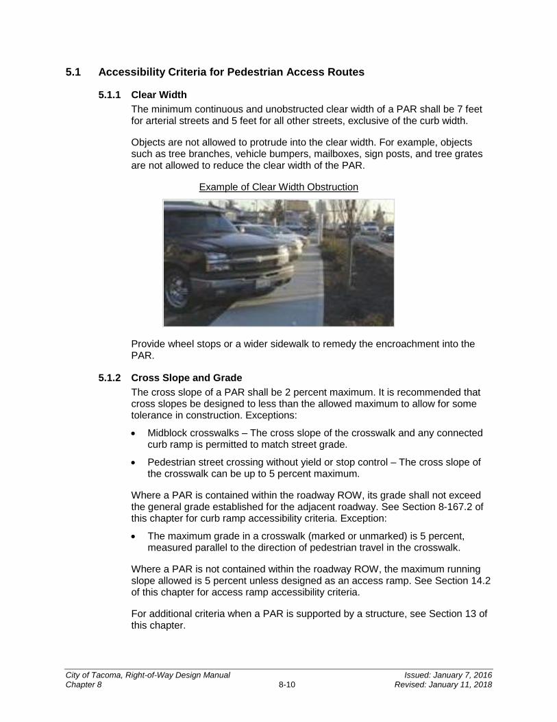
5.1 Accessibility Criteria for Pedestrian Access Routes
5.1.1 Clear Width The minimum continuous and unobstructed clear width of a PAR shall be 7 feet for arterial streets and 5 feet for all other streets, exclusive of the curb width.
Objects are not allowed to protrude into the clear width. For example, objects such as tree branches, vehicle bumpers, mailboxes, sign posts, and tree grates are not allowed to reduce the clear width of the PAR.
Example of Clear Width Obstruction
Provide wheel stops or a wider sidewalk to remedy the encroachment into the PAR.
5.1.2 Cross Slope and Grade The cross slope of a PAR shall be 2 percent maximum. It is recommended that cross slopes be designed to less than the allowed maximum to allow for some tolerance in construction. Exceptions:
• Midblock crosswalks – The cross slope of the crosswalk and any connected curb ramp is permitted to match street grade.
• Pedestrian street crossing without yield or stop control – The cross slope of the crosswalk can be up to 5 percent maximum.
Where a PAR is contained within the roadway ROW, its grade shall not exceed the general grade established for the adjacent roadway. See Section 8-167.2 of this chapter for curb ramp accessibility criteria. Exception:
• The maximum grade in a crosswalk (marked or unmarked) is 5 percent, measured parallel to the direction of pedestrian travel in the crosswalk.
Where a PAR is not contained within the roadway ROW, the maximum running slope allowed is 5 percent unless designed as an access ramp. See Section 14.2 of this chapter for access ramp accessibility criteria.
For additional criteria when a PAR is supported by a structure, see Section 13 of this chapter.
City of Tacoma, Right-of-Way Design Manual Issued: January 7, 2016 Chapter 8 8-10 Revised: January 11, 2018
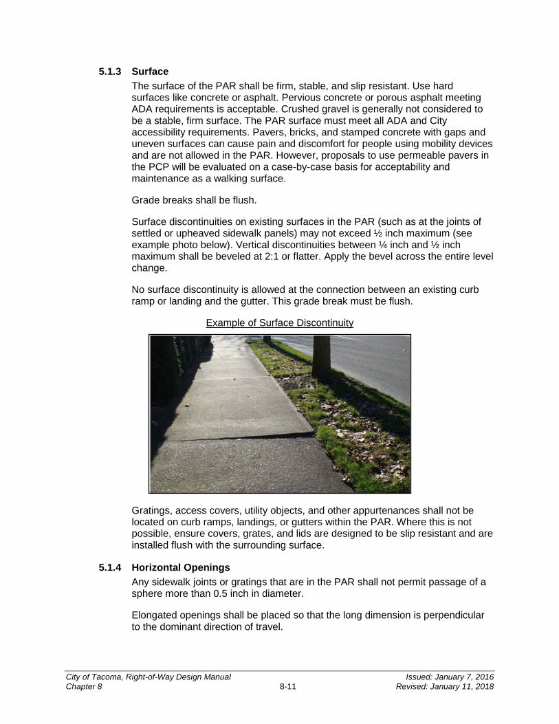
5.1.3 Surface The surface of the PAR shall be firm, stable, and slip resistant. Use hard surfaces like concrete or asphalt. Pervious concrete or porous asphalt meeting ADA requirements is acceptable. Crushed gravel is generally not considered to be a stable, firm surface. The PAR surface must meet all ADA and City accessibility requirements. Pavers, bricks, and stamped concrete with gaps and uneven surfaces can cause pain and discomfort for people using mobility devices and are not allowed in the PAR. However, proposals to use permeable pavers in the PCP will be evaluated on a case-by-case basis for acceptability and maintenance as a walking surface.
Grade breaks shall be flush.
Surface discontinuities on existing surfaces in the PAR (such as at the joints of settled or upheaved sidewalk panels) may not exceed ½ inch maximum (see example photo below). Vertical discontinuities between ¼ inch and ½ inch maximum shall be beveled at 2:1 or flatter. Apply the bevel across the entire level change.
No surface discontinuity is allowed at the connection between an existing curb ramp or landing and the gutter. This grade break must be flush.
Example of Surface Discontinuity
Gratings, access covers, utility objects, and other appurtenances shall not be located on curb ramps, landings, or gutters within the PAR. Where this is not possible, ensure covers, grates, and lids are designed to be slip resistant and are installed flush with the surrounding surface.
5.1.4 Horizontal Openings Any sidewalk joints or gratings that are in the PAR shall not permit passage of a sphere more than 0.5 inch in diameter.
Elongated openings shall be placed so that the long dimension is perpendicular to the dominant direction of travel.
City of Tacoma, Right-of-Way Design Manual Issued: January 7, 2016 Chapter 8 8-11 Revised: January 11, 2018

Openings for wheel flanges at pedestrian crossings of non-freight rail track shall be 2.5 inches maximum (3 inches maximum for freight rail track).
For additional requirements when a PAR crosses a railroad, see Section 12 of this chapter.
SECTION 6 Sidewalks
Sidewalks are one type of PCP; see Section 4 of this chapter for PCP accessibility criteria. Plan the design of sidewalks carefully to include a PAR that provides universal access; see Section 5 of this chapter for PAR accessibility criteria. Wherever appropriate make sidewalks continuous and provide access to side streets. The preferred installation for the PAR is a sidewalk separated from the traveled way by a planted buffer. This provides a greater separation between vehicles and pedestrians than curb alone.
6.1 Sidewalk and Buffer Widths The City minimum standard residential sidewalk width is 5 feet (excluding the curb width and required planting strip). Adjacent to arterials, sidewalk widths shall be a minimum of 7 feet (excluding the curb width and buffer or planting strip), unless specified in the TMC or design guidelines. For example, minimum widths for mixed-use centers shall be superseded by the mixed-use center design criteria found in TMC 13.06.300. A 10 to 12 foot sidewalk is preferred for high pedestrian traffic and commercial areas. Wider sidewalks may also be required adjacent to angle parking to account for vehicle overhang. Refer to CHAPTER 4 for additional information.
When a buffer is provided, the buffer should be at least 5 feet wide (excluding the curb width). Prior approval must be obtained from the City Engineer or designee to reduce a buffer width to less than 5 feet.
Design subsurface infrastructure (such as structural soils) and select plants whose root systems do not cause sidewalks to buckle or heave. Refer to CHAPTER 9 for additional information.
Objects are not allowed to protrude into the clear width. For example, objects such as tree branches, vehicle bumpers, mailboxes, sign posts, and tree grates are not allowed to reduce the clear width of the sidewalk.
Shoulders, bike lanes, and on-street parking are not considered buffers, but they do offer the advantage of further separation between vehicles and pedestrians.
6.2 Sidewalks at Driveways Provide a PAR where driveways intersect a PCP. See Standard Plans SU-07, SU-08, SU-09, and HD-NS02 for details of driveway designs that provide a PAR. See Section 4 and Section 5 of this chapter for accessibility criteria. When a driveway is signalized as part of an intersection, contact the ADA Coordinator at (253) 591-5785 for guidance on the design of the sidewalk.
City of Tacoma, Right-of-Way Design Manual Issued: January 7, 2016 Chapter 8 8-12 Revised: January 11, 2018
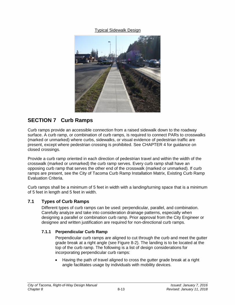
Typical Sidewalk Design
SECTION 7 Curb Ramps Curb ramps provide an accessible connection from a raised sidewalk down to the roadway surface. A curb ramp, or combination of curb ramps, is required to connect PARs to crosswalks (marked or unmarked) where curbs, sidewalks, or visual evidence of pedestrian traffic are present, except where pedestrian crossing is prohibited. See CHAPTER 4 for guidance on closed crossings.
Provide a curb ramp oriented in each direction of pedestrian travel and within the width of the crosswalk (marked or unmarked) the curb ramp serves. Every curb ramp shall have an opposing curb ramp that serves the other end of the crosswalk (marked or unmarked). If curb ramps are present, see the City of Tacoma Curb Ramp Installation Matrix, Existing Curb Ramp Evaluation Criteria.
Curb ramps shall be a minimum of 5 feet in width with a landing/turning space that is a minimum of 5 feet in length and 5 feet in width.
7.1 Types of Curb Ramps Different types of curb ramps can be used: perpendicular, parallel, and combination. Carefully analyze and take into consideration drainage patterns, especially when designing a parallel or combination curb ramp. Prior approval from the City Engineer or designee and written justification are required for non-directional curb ramps.
7.1.1 Perpendicular Curb Ramp Perpendicular curb ramps are aligned to cut through the curb and meet the gutter grade break at a right angle (see Figure 8-2). The landing is to be located at the top of the curb ramp. The following is a list of design considerations for incorporating perpendicular curb ramps:
• Having the path of travel aligned to cross the gutter grade break at a right angle facilitates usage by individuals with mobility devices.
City of Tacoma, Right-of-Way Design Manual Issued: January 7, 2016 Chapter 8 8-13 Revised: January 11, 2018
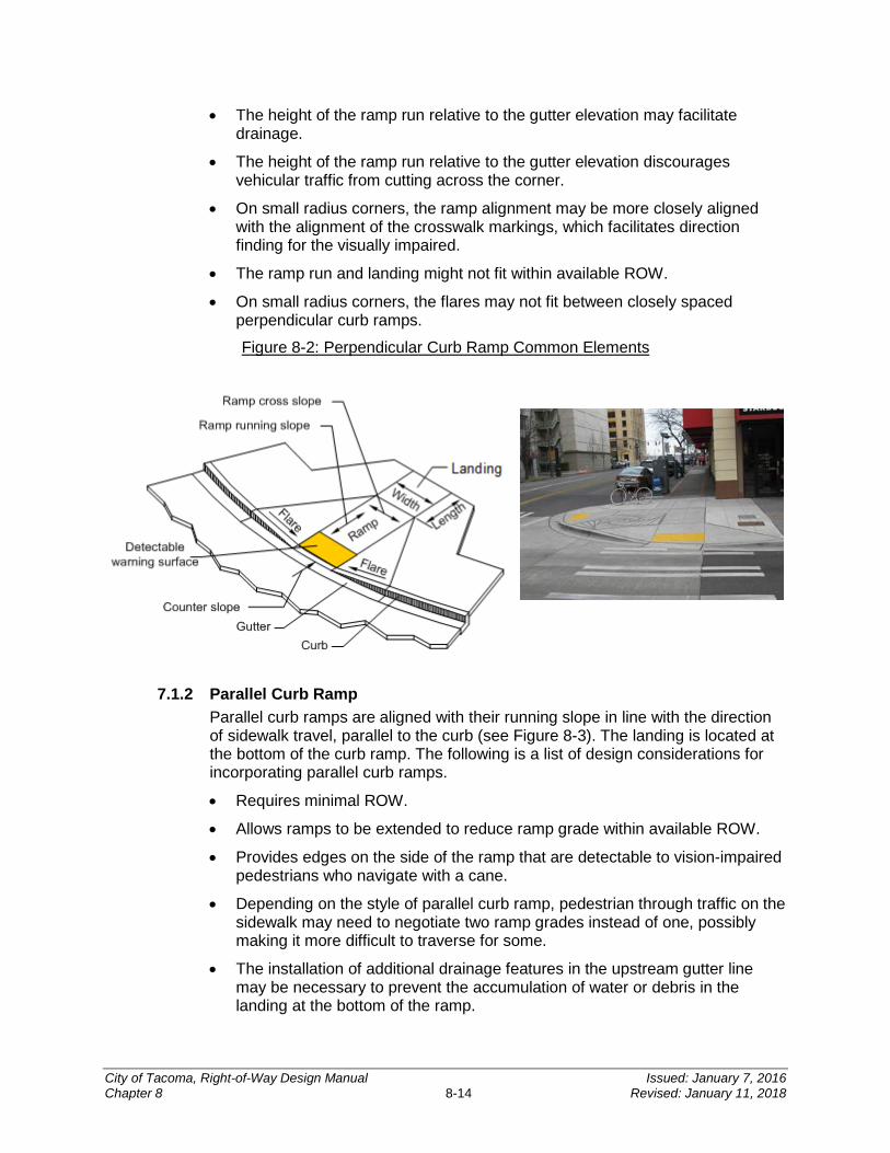
• The height of the ramp run relative to the gutter elevation may facilitate drainage.
• The height of the ramp run relative to the gutter elevation discourages vehicular traffic from cutting across the corner.
• On small radius corners, the ramp alignment may be more closely aligned with the alignment of the crosswalk markings, which facilitates direction finding for the visually impaired.
• The ramp run and landing might not fit within available ROW.
• On small radius corners, the flares may not fit between closely spaced perpendicular curb ramps.
Figure 8-2: Perpendicular Curb Ramp Common Elements
7.1.2 Parallel Curb Ramp Parallel curb ramps are aligned with their running slope in line with the direction of sidewalk travel, parallel to the curb (see Figure 8-3). The landing is located at the bottom of the curb ramp. The following is a list of design considerations for incorporating parallel curb ramps.
• Requires minimal ROW.
• Allows ramps to be extended to reduce ramp grade within available ROW.
• Provides edges on the side of the ramp that are detectable to vision-impaired pedestrians who navigate with a cane.
• Depending on the style of parallel curb ramp, pedestrian through traffic on the sidewalk may need to negotiate two ramp grades instead of one, possibly making it more difficult to traverse for some.
• The installation of additional drainage features in the upstream gutter line may be necessary to prevent the accumulation of water or debris in the landing at the bottom of the ramp.
City of Tacoma, Right-of-Way Design Manual Issued: January 7, 2016 Chapter 8 8-14 Revised: January 11, 2018

Figure 8-3: Parallel Curb Ramp Common Elements
Note: The pedestrian curb shown on the back of the curb ramp is intended to retain material in a cut section and is not required if there is no material to retain due to the nature of the street topography.
7.1.3 Combination Curb Ramp Combination curb ramps combine the use of perpendicular and parallel types of curb ramps (see photo below). Landings may be shared by multiple ramps in this application. Buffer areas and pedestrian curbing that define the pedestrian path of travel are inherent design elements for this type of curb ramp. The following is a list of design considerations for incorporating combination curb ramps:
• Allows the elevation difference between the sidewalk and the gutter line to be transitioned with multiple ramps. This can help achieve compliant ramp running slopes.
• Provides additional locations in the gutter line along the radius where drainage structures can be placed outside the PAR due to the well-defined pedestrian paths of travel.
• Can be constructed within available ROW when the ROW boundary is located at the back of the existing sidewalk, provided sufficient buffer width is available on the roadway side of the sidewalk.
• Provides a way to avoid the relocation of existing features such as utility poles, fire hydrants, and signal poles by incorporating those features into the buffer areas.
• The pedestrian curbing that defines the buffer areas and forms the curb returns for the perpendicular ramp connections facilitates direction finding for a vision-impaired person who navigates with a cane.
• Has a higher construction cost than other curb ramp types due to extensive use of curbing and a larger footprint.
City of Tacoma, Right-of-Way Design Manual Issued: January 7, 2016 Chapter 8 8-15 Revised: January 11, 2018
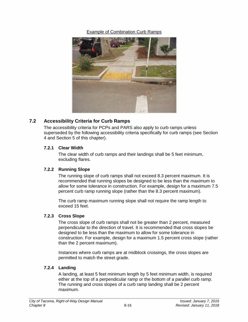
Example of Combination Curb Ramps
7.2 Accessibility Criteria for Curb Ramps The accessibility criteria for PCPs and PARS also apply to curb ramps unless superseded by the following accessibility criteria specifically for curb ramps (see Section 4 and Section 5 of this chapter).
7.2.1 Clear Width The clear width of curb ramps and their landings shall be 5 feet minimum, excluding flares.
7.2.2 Running Slope The running slope of curb ramps shall not exceed 8.3 percent maximum. It is recommended that running slopes be designed to be less than the maximum to allow for some tolerance in construction. For example, design for a maximum 7.5 percent curb ramp running slope (rather than the 8.3 percent maximum).
The curb ramp maximum running slope shall not require the ramp length to exceed 15 feet.
7.2.3 Cross Slope The cross slope of curb ramps shall not be greater than 2 percent, measured perpendicular to the direction of travel. It is recommended that cross slopes be designed to be less than the maximum to allow for some tolerance in construction. For example, design for a maximum 1.5 percent cross slope (rather than the 2 percent maximum).
Instances where curb ramps are at midblock crossings, the cross slopes are permitted to match the street grade.
7.2.4 Landing A landing, at least 5 feet minimum length by 5 feet minimum width, is required either at the top of a perpendicular ramp or the bottom of a parallel curb ramp. The running and cross slopes of a curb ramp landing shall be 2 percent maximum.
City of Tacoma, Right-of-Way Design Manual Issued: January 7, 2016 Chapter 8 8-16 Revised: January 11, 2018
7.2.5 Flares and Pedestrian Curbing Flared sides are to be used where a PCP crosses the curb ramp from the side. Flared sides are to have a slope of 10 percent maximum, measured parallel to the back of curb.
Pedestrian curbs are to be used only where there is landscaping or other appurtenances, such as railing, that prevent cross travel by pedestrians. Pedestrian curbs are to be located outside the PCP. Pedestrian curbs may not be used to prevent pedestrians from using street crossings.
7.2.6 Counter Slope The counter slope of the gutter or street at the foot of a curb ramp or landing shall be 5 percent maximum.
7.2.7 Detectable Warning Surfaces Detectable warning surfaces are required where curb ramps or landings connect to a street, or at alleys and driveways with high traffic volumes. Detectable warning surfaces shall contrast visually with the adjacent walkway surface, gutter, or street (see the City Standard Plans for placement details and other applications).
7.2.8 Surfaces Surfaces of curb ramps shall be firm, stable, and slip resistant. Gratings, access covers, utility objects, and other appurtenances shall not be located on curb ramps, landings, or gutters within the PAR. See Section 5 of this chapter for more information.
7.2.9 Grade Breaks Grade breaks at the top and bottom of curb ramps shall be perpendicular to the direction of travel. Surface slopes that meet at grade breaks shall be flush.
7.2.10 Clear Space A clear space, to facilitate pedestrian turning maneuvers, is required within the roadway for all non-directional curb ramps. The 4 foot (minimum) by 4 foot (minimum) clear space shall be located beyond the curb face where the bottom of a non-directional curb ramp or landing meets the gutter, contained within the width of the crosswalk, and located completely outside the parallel vehicle travel lane.
7.3 Curb Ramp Drainage Stormwater runoff from the roadway can flood the lower end of a curb ramp. Measures to prevent ponding at the base of curb ramps and landings (see Figure 8-4) must be taken. Refer to Chapter 11 Section 6 Curb Ramps for guidance and requirements. Verify that drainage structures will not be located in the PAR. Refer to the SWMM for additional information.
City of Tacoma, Right-of-Way Design Manual Issued: January 7, 2016 Chapter 8 8-17 Revised: January 11, 2018
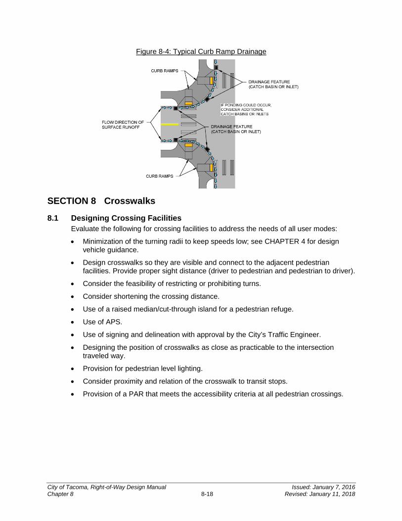
Figure 8-4: Typical Curb Ramp Drainage
SECTION 8 Crosswalks
8.1 Designing Crossing Facilities Evaluate the following for crossing facilities to address the needs of all user modes:
• Minimization of the turning radii to keep speeds low; see CHAPTER 4 for design vehicle guidance.
• Design crosswalks so they are visible and connect to the adjacent pedestrian facilities. Provide proper sight distance (driver to pedestrian and pedestrian to driver).
• Consider the feasibility of restricting or prohibiting turns.
• Consider shortening the crossing distance.
• Use of a raised median/cut-through island for a pedestrian refuge.
• Use of APS.
• Use of signing and delineation with approval by the City’s Traffic Engineer.
• Designing the position of crosswalks as close as practicable to the intersection traveled way.
• Provision for pedestrian level lighting.
• Consider proximity and relation of the crosswalk to transit stops.
• Provision of a PAR that meets the accessibility criteria at all pedestrian crossings.
City of Tacoma, Right-of-Way Design Manual Issued: January 7, 2016 Chapter 8 8-18 Revised: January 11, 2018
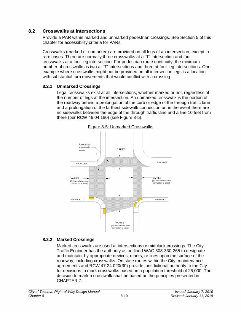
8.2 Crosswalks at Intersections Provide a PAR within marked and unmarked pedestrian crossings. See Section 5 of this chapter for accessibility criteria for PARs.
Crosswalks (marked or unmarked) are provided on all legs of an intersection, except in rare cases. There are normally three crosswalks at a “T” intersection and four crosswalks at a four-leg intersection. For pedestrian route continuity, the minimum number of crosswalks is two at “T” intersections and three at four-leg intersections. One example where crosswalks might not be provided on all intersection legs is a location with substantial turn movements that would conflict with a crossing.
8.2.1 Unmarked Crossings Legal crosswalks exist at all intersections, whether marked or not, regardless of the number of legs at the intersection. An unmarked crosswalk is the portion of the roadway behind a prolongation of the curb or edge of the through traffic lane and a prolongation of the farthest sidewalk connection or, in the event there are no sidewalks between the edge of the through traffic lane and a line 10 feet from there (per RCW 46.04.160) (see Figure 8-5).
Figure 8-5: Unmarked Crosswalks
Unmarked crosswalk areas
VARIES(To back of curb rampconnection to street)
10 FEET
SHOULDER
SIDEWALKSIDEWALK
VARIES(To back of curb rampconnection to street)
VARIES(To back of curb rampconnection to street)
SHOULDER
8.2.2 Marked Crossings Marked crosswalks are used at intersections or midblock crossings. The City Traffic Engineer has the authority as outlined WAC 308-330-265 to designate and maintain, by appropriate devices, marks, or lines upon the surface of the roadway, including crosswalks. On state routes within the City, maintenance agreements and RCW 47.24.020(30) provide jurisdictional authority to the City for decisions to mark crosswalks based on a population threshold of 25,000. The decision to mark a crosswalk shall be based on the principles presented in CHAPTER 7.
City of Tacoma, Right-of-Way Design Manual Issued: January 7, 2016 Chapter 8 8-19 Revised: January 11, 2018
The City Traffic Engineer makes the final determination on appropriate signing, delineation, and/or other treatments. Standard width for a marked crosswalk is 10 feet although reduced widths (no less than 6 feet) may be considered with justification. The preferred type of marked crosswalk is a longitudinal pattern known as “continental,” which is shown in the Standard Plans. Stop and yield line dimensions and placement must conform to the MUTCD and are shown in the Standard Plans.
Some decorative crosswalk materials (such as colored pavement) may cause confusion for visually impaired pedestrians. Crosswalks are distinct elements of the PAR (see Section 5 of this chapter). Pavers, bricks, and stamped concrete with gaps and uneven surfaces can cause pain and discomfort for people using mobility devices and are not allowed in the PAR. Decorative crosswalks should be supplemented with standard style pavement markings to enhance visibility and delineate the crosswalk. Refer to CHAPTER 7 for additional information (also refer to the MUTCD.)
8.2.3 Closed Crossings Pedestrian crossings shall only be closed for a documented reason such as observed crash concerns or for essential signal operations. If an existing crossing has been closed, as indicated by existing signing, provide an appropriate treatment such as a railing that is detectable by people with vision difficulties who navigate with a cane. The City Traffic Engineer is the approval authority for the closing of crossings.
8.3 Midblock Crosswalks On roadways with pedestrian crossing traffic caused by nearby pedestrian generators, a midblock crossing may be appropriate. See CHAPTER 7 for crosswalk criteria and the MoMaP Pedestrian and Bicycle Guidelines for marked crosswalk recommendations at un-signalized intersections.
As with marked crosswalks at intersections, the creation and marking of midblock crosswalks shall not be implemented indiscriminately. Engineering judgment of various conditions that would be beneficial or unintended consequences of marking the midblock crossing shall be exercised and documented by the proposing party. The approval authority for any proposed crosswalks is the City Traffic Engineer. If approved, the PAR in the midblock crosswalk can have a cross slope that matches the grade of the roadway in order to meet accessibility criteria.
8.4 Sight Distance at Crosswalks When locating crosswalks at intersections, it is important to evaluate the sight lines between pedestrians and motorists. Shrubbery, signs, parked cars, and other roadside elements can block motorists’ and pedestrians’ views of one another. Figure 8-6 illustrates these sight distance concerns.
City of Tacoma, Right-of-Way Design Manual Issued: January 7, 2016 Chapter 8 8-20 Revised: January 11, 2018

Figure 8-6: Obstructed Line of Sight at Intersection
Parked cars
Conventional right-turncurb radius
Parked car obstructs line of sight
Driver's line of sight
Pedestrian waiting tocross street
Crosswalk
Approaching vehicle
Pedestrian waiting to cross street
Crosswalk
Right-turning vehicle
Driver's line of sight
Object blocking driver's line of sight
8.5 Curb Extensions Curb extensions (also known as “curb bulbs” or “bulbouts”) are traffic calming measures that may improve sight distance and reduce pedestrian crossing times, which limit pedestrian exposure to traffic. Installing a curb extension can help reduce the sight distance problem with parked cars that limit driver/pedestrian visibility. Curb extensions may allow for better curb ramp design as well as provide more space for pedestrians. The design of curb extensions may necessitate the removal of parking and/or may need to consider the needs of existing or future bicycle lanes. See CHAPTER 4 for more information.
Extend the curb no farther than the width of the parking lane. The curb extension shall not interfere with the conflicting vehicle travel path. Design the approach nose to ensure adequate setback of vehicles to provide visibility of pedestrians. At intersections with traffic signals, the curb extensions can be used to reduce the pedestrian signal clearance interval. Examples of sidewalk curb extensions are shown in Figure 8-7.
City of Tacoma, Right-of-Way Design Manual Issued: January 7, 2016 Chapter 8 8-21 Revised: January 11, 2018
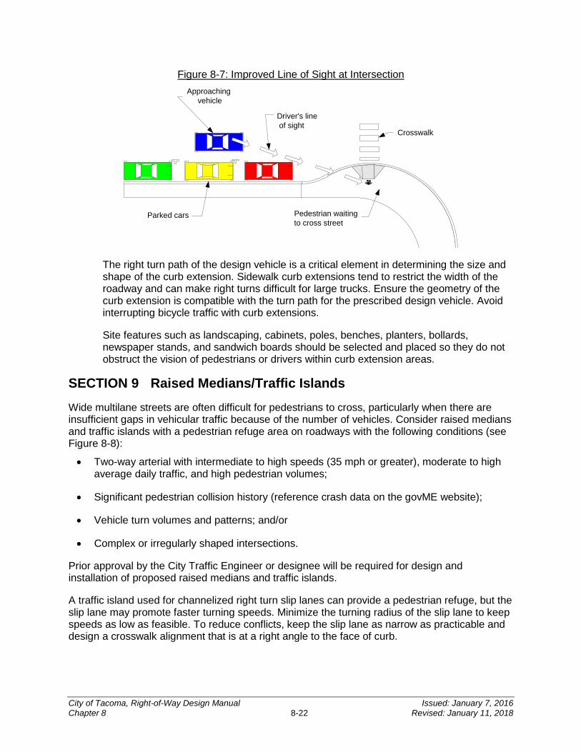
Figure 8-7: Improved Line of Sight at Intersection
Crosswalk
Driver's line of sight
Approaching vehicle
Parked cars Pedestrian waitingto cross street
The right turn path of the design vehicle is a critical element in determining the size and shape of the curb extension. Sidewalk curb extensions tend to restrict the width of the roadway and can make right turns difficult for large trucks. Ensure the geometry of the curb extension is compatible with the turn path for the prescribed design vehicle. Avoid interrupting bicycle traffic with curb extensions.
Site features such as landscaping, cabinets, poles, benches, planters, bollards, newspaper stands, and sandwich boards should be selected and placed so they do not obstruct the vision of pedestrians or drivers within curb extension areas.
SECTION 9 Raised Medians/Traffic Islands
Wide multilane streets are often difficult for pedestrians to cross, particularly when there are insufficient gaps in vehicular traffic because of the number of vehicles. Consider raised medians and traffic islands with a pedestrian refuge area on roadways with the following conditions (see Figure 8-8):
• Two-way arterial with intermediate to high speeds (35 mph or greater), moderate to high average daily traffic, and high pedestrian volumes;
• Significant pedestrian collision history (reference crash data on the govME website);
• Vehicle turn volumes and patterns; and/or
• Complex or irregularly shaped intersections.
Prior approval by the City Traffic Engineer or designee will be required for design and installation of proposed raised medians and traffic islands.
A traffic island used for channelized right turn slip lanes can provide a pedestrian refuge, but the slip lane may promote faster turning speeds. Minimize the turning radius of the slip lane to keep speeds as low as feasible. To reduce conflicts, keep the slip lane as narrow as practicable and design a crosswalk alignment that is at a right angle to the face of curb.
City of Tacoma, Right-of-Way Design Manual Issued: January 7, 2016 Chapter 8 8-22 Revised: January 11, 2018
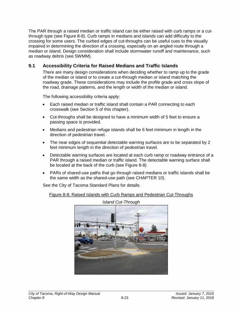
The PAR through a raised median or traffic island can be either raised with curb ramps or a cut-through type (see Figure 8-8). Curb ramps in medians and islands can add difficulty to the crossing for some users. The curbed edges of cut-throughs can be useful cues to the visually impaired in determining the direction of a crossing, especially on an angled route through a median or island. Design consideration shall include stormwater runoff and maintenance, such as roadway debris (see SWMM).
9.1 Accessibility Criteria for Raised Medians and Traffic Islands There are many design considerations when deciding whether to ramp up to the grade of the median or island or to create a cut-through median or island matching the roadway grade. These considerations may include the profile grade and cross slope of the road, drainage patterns, and the length or width of the median or island.
The following accessibility criteria apply:
• Each raised median or traffic island shall contain a PAR connecting to each crosswalk (see Section 5 of this chapter).
• Cut-throughs shall be designed to have a minimum width of 5 feet to ensure a passing space is provided.
• Medians and pedestrian refuge islands shall be 6 feet minimum in length in the direction of pedestrian travel.
• The near edges of sequential detectable warning surfaces are to be separated by 2 feet minimum length in the direction of pedestrian travel.
• Detectable warning surfaces are located at each curb ramp or roadway entrance of a PAR through a raised median or traffic island. The detectable warning surface shall be located at the back of the curb (see Figure 8-8)
• PARs of shared-use paths that go through raised medians or traffic islands shall be the same width as the shared-use path (see CHAPTER 10).
See the City of Tacoma Standard Plans for details.
Figure 8-8: Raised Islands with Curb Ramps and Pedestrian Cut-Throughs
Island Cut-Through
City of Tacoma, Right-of-Way Design Manual Issued: January 7, 2016 Chapter 8 8-23 Revised: January 11, 2018
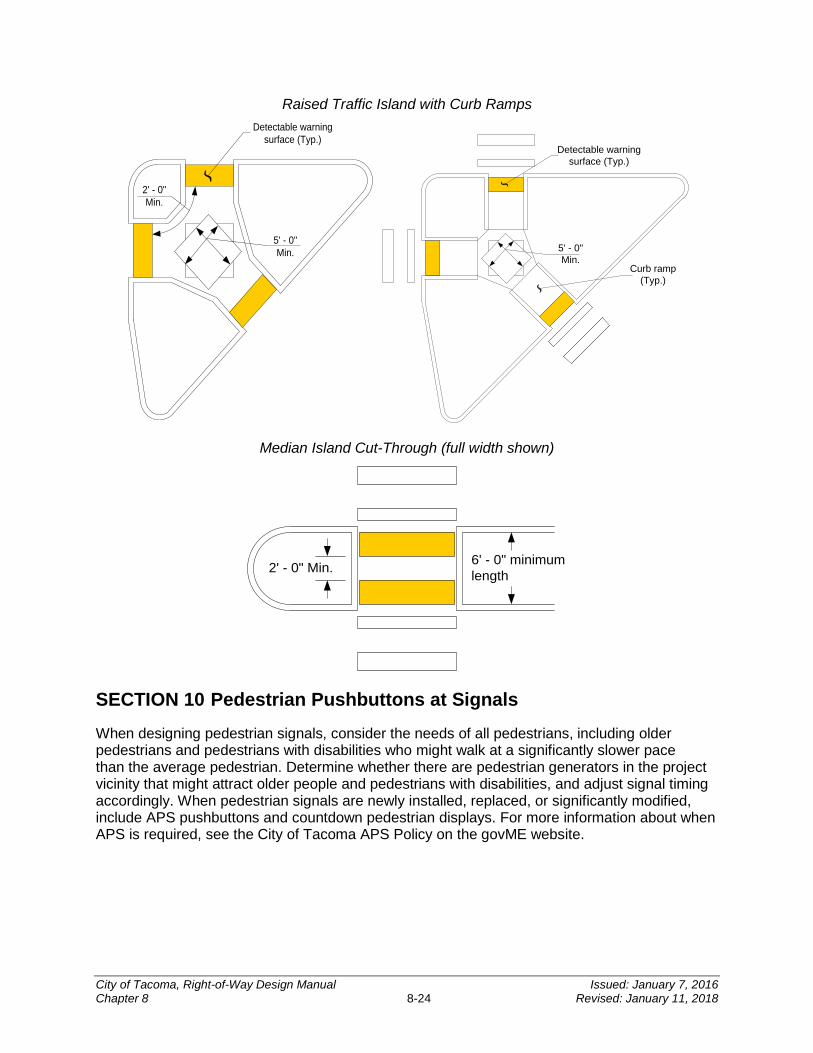
Raised Traffic Island with Curb Ramps
5' - 0"Min.
2' - 0"Min.
Detectable warning surface (Typ.)
5' - 0"Min.
Curb ramp(Typ.)
Detectable warning surface (Typ.)
Median Island Cut-Through (full width shown)
6' - 0" minimum length2' - 0" Min.
SECTION 10 Pedestrian Pushbuttons at Signals
When designing pedestrian signals, consider the needs of all pedestrians, including older pedestrians and pedestrians with disabilities who might walk at a significantly slower pace than the average pedestrian. Determine whether there are pedestrian generators in the project vicinity that might attract older people and pedestrians with disabilities, and adjust signal timing accordingly. When pedestrian signals are newly installed, replaced, or significantly modified, include APS pushbuttons and countdown pedestrian displays. For more information about when APS is required, see the City of Tacoma APS Policy on the govME website.
City of Tacoma, Right-of-Way Design Manual Issued: January 7, 2016 Chapter 8 8-24 Revised: January 11, 2018
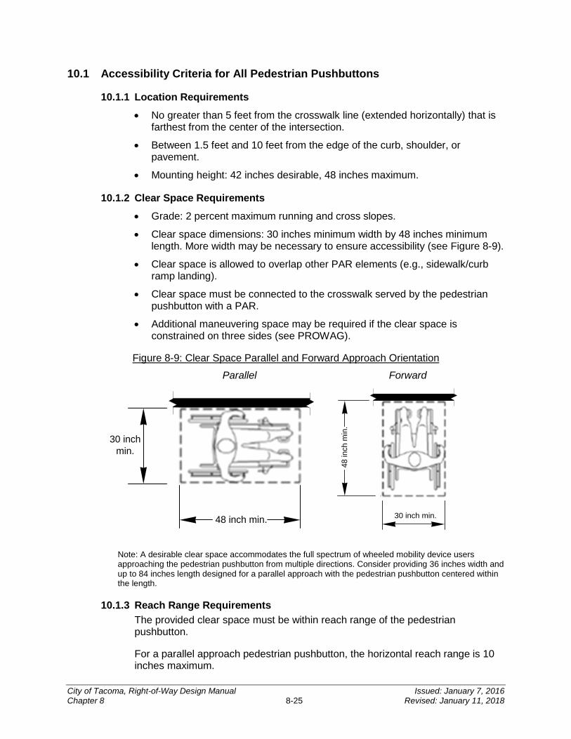
10.1 Accessibility Criteria for All Pedestrian Pushbuttons
10.1.1 Location Requirements
• No greater than 5 feet from the crosswalk line (extended horizontally) that is farthest from the center of the intersection.
• Between 1.5 feet and 10 feet from the edge of the curb, shoulder, or pavement.
• Mounting height: 42 inches desirable, 48 inches maximum.
10.1.2 Clear Space Requirements
• Grade: 2 percent maximum running and cross slopes.
• Clear space dimensions: 30 inches minimum width by 48 inches minimum length. More width may be necessary to ensure accessibility (see Figure 8-9).
• Clear space is allowed to overlap other PAR elements (e.g., sidewalk/curb ramp landing).
• Clear space must be connected to the crosswalk served by the pedestrian pushbutton with a PAR.
• Additional maneuvering space may be required if the clear space is constrained on three sides (see PROWAG).
Figure 8-9: Clear Space Parallel and Forward Approach Orientation
Parallel Forward
30 inch min.
48 inch min.
48
inch
min
.
30 inch min.
Note: A desirable clear space accommodates the full spectrum of wheeled mobility device users approaching the pedestrian pushbutton from multiple directions. Consider providing 36 inches width and up to 84 inches length designed for a parallel approach with the pedestrian pushbutton centered within the length.
10.1.3 Reach Range Requirements The provided clear space must be within reach range of the pedestrian pushbutton.
For a parallel approach pedestrian pushbutton, the horizontal reach range is 10 inches maximum.
City of Tacoma, Right-of-Way Design Manual Issued: January 7, 2016 Chapter 8 8-25 Revised: January 11, 2018
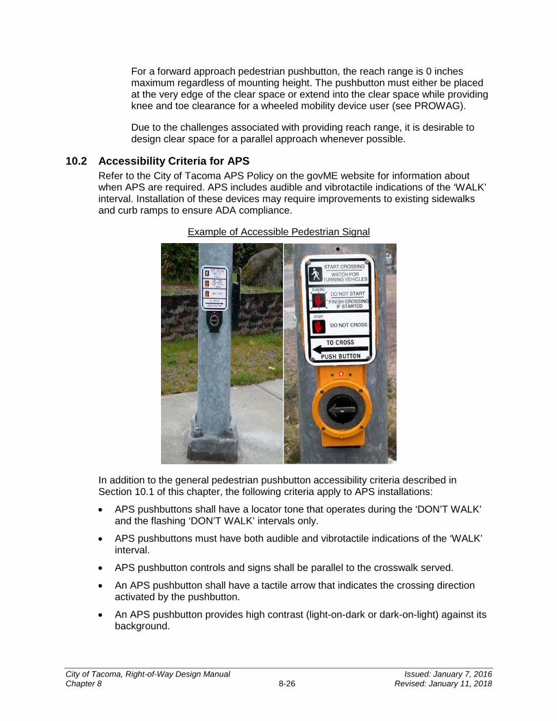
For a forward approach pedestrian pushbutton, the reach range is 0 inches maximum regardless of mounting height. The pushbutton must either be placed at the very edge of the clear space or extend into the clear space while providing knee and toe clearance for a wheeled mobility device user (see PROWAG).
Due to the challenges associated with providing reach range, it is desirable to design clear space for a parallel approach whenever possible.
10.2 Accessibility Criteria for APS Refer to the City of Tacoma APS Policy on the govME website for information about when APS are required. APS includes audible and vibrotactile indications of the ‘WALK’ interval. Installation of these devices may require improvements to existing sidewalks and curb ramps to ensure ADA compliance.
Example of Accessible Pedestrian Signal
In addition to the general pedestrian pushbutton accessibility criteria described in Section 10.1 of this chapter, the following criteria apply to APS installations:
• APS pushbuttons shall have a locator tone that operates during the ‘DON’T WALK’ and the flashing ‘DON’T WALK’ intervals only.
• APS pushbuttons must have both audible and vibrotactile indications of the ‘WALK’ interval.
• APS pushbutton controls and signs shall be parallel to the crosswalk served.
• An APS pushbutton shall have a tactile arrow that indicates the crossing direction activated by the pushbutton.
• An APS pushbutton provides high contrast (light-on-dark or dark-on-light) against its background.
City of Tacoma, Right-of-Way Design Manual Issued: January 7, 2016 Chapter 8 8-26 Revised: January 11, 2018
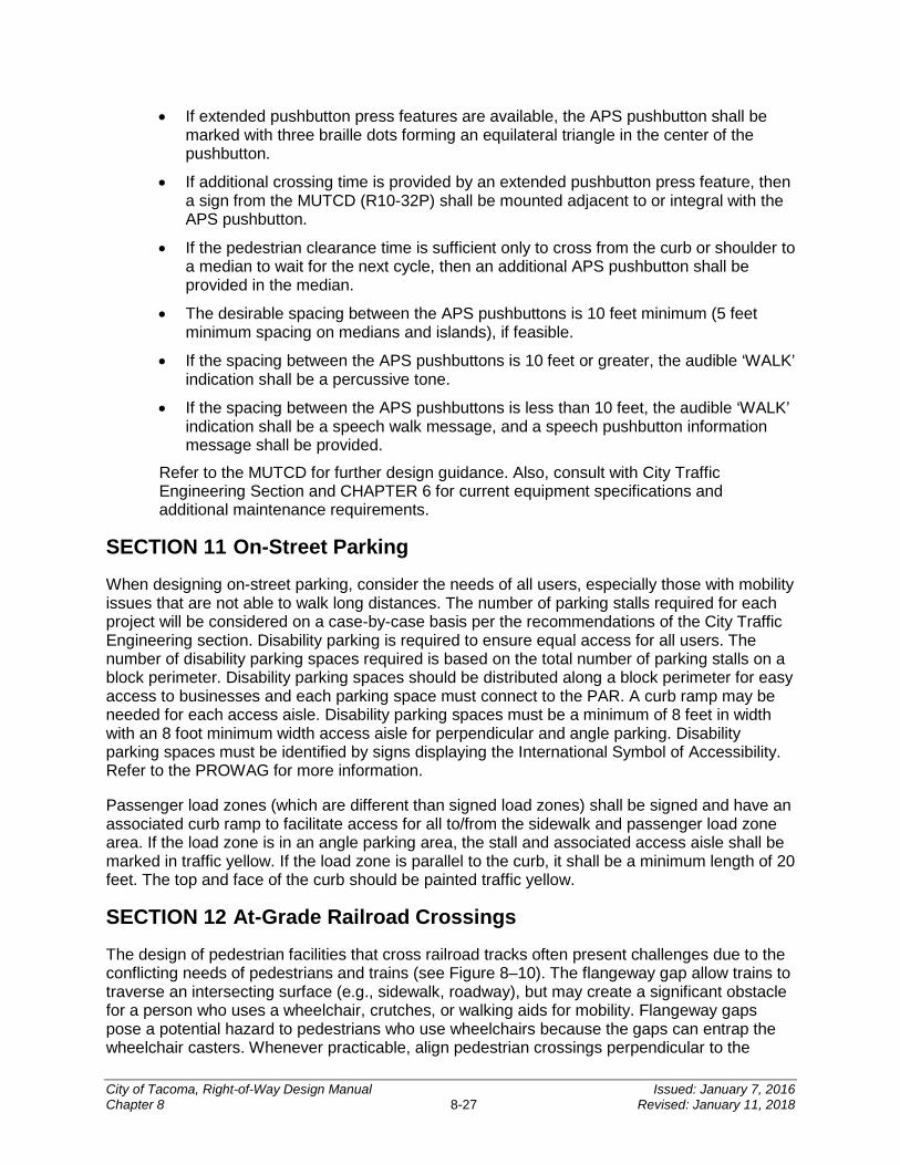
• If extended pushbutton press features are available, the APS pushbutton shall be marked with three braille dots forming an equilateral triangle in the center of the pushbutton.
• If additional crossing time is provided by an extended pushbutton press feature, then a sign from the MUTCD (R10-32P) shall be mounted adjacent to or integral with the APS pushbutton.
• If the pedestrian clearance time is sufficient only to cross from the curb or shoulder to a median to wait for the next cycle, then an additional APS pushbutton shall be provided in the median.
• The desirable spacing between the APS pushbuttons is 10 feet minimum (5 feet minimum spacing on medians and islands), if feasible.
• If the spacing between the APS pushbuttons is 10 feet or greater, the audible ‘WALK’ indication shall be a percussive tone.
• If the spacing between the APS pushbuttons is less than 10 feet, the audible ‘WALK’ indication shall be a speech walk message, and a speech pushbutton information message shall be provided.
Refer to the MUTCD for further design guidance. Also, consult with City Traffic Engineering Section and CHAPTER 6 for current equipment specifications and additional maintenance requirements.
SECTION 11 On-Street Parking
When designing on-street parking, consider the needs of all users, especially those with mobility issues that are not able to walk long distances. The number of parking stalls required for each project will be considered on a case-by-case basis per the recommendations of the City Traffic Engineering section. Disability parking is required to ensure equal access for all users. The number of disability parking spaces required is based on the total number of parking stalls on a block perimeter. Disability parking spaces should be distributed along a block perimeter for easy access to businesses and each parking space must connect to the PAR. A curb ramp may be needed for each access aisle. Disability parking spaces must be a minimum of 8 feet in width with an 8 foot minimum width access aisle for perpendicular and angle parking. Disability parking spaces must be identified by signs displaying the International Symbol of Accessibility. Refer to the PROWAG for more information.
Passenger load zones (which are different than signed load zones) shall be signed and have an associated curb ramp to facilitate access for all to/from the sidewalk and passenger load zone area. If the load zone is in an angle parking area, the stall and associated access aisle shall be marked in traffic yellow. If the load zone is parallel to the curb, it shall be a minimum length of 20 feet. The top and face of the curb should be painted traffic yellow.
SECTION 12 At-Grade Railroad Crossings
The design of pedestrian facilities that cross railroad tracks often present challenges due to the conflicting needs of pedestrians and trains (see Figure 8–10). The flangeway gap allow trains to traverse an intersecting surface (e.g., sidewalk, roadway), but may create a significant obstacle for a person who uses a wheelchair, crutches, or walking aids for mobility. Flangeway gaps pose a potential hazard to pedestrians who use wheelchairs because the gaps can entrap the wheelchair casters. Whenever practicable, align pedestrian crossings perpendicular to the
City of Tacoma, Right-of-Way Design Manual Issued: January 7, 2016 Chapter 8 8-27 Revised: January 11, 2018
tracks in order to minimize potential problems related to flangeway gaps. Crossing surfaces may be constructed of asphalt, rubberized materials, or concrete. Concrete materials generally provide the smoothest and most durable crossing surfaces.
Flangeway gaps at pedestrian at-grade rail crossings shall be 2.5 inches maximum on non-freight rail track and 3 inches maximum on freight rail track (see Figure 8–10).
Figure 8–10: Flangeway Gaps
When detectable warning surfaces are used at railroad crossings, place them according to the MUTCD stop line placement criteria.
There are a number of railroad crossing warning devices intended specifically for pedestrian facilities (see the MUTCD). When selecting warning devices, factors such as train and pedestrian volumes, train speeds, available sight distance, number of tracks, and other site-specific characteristics should be taken into account. Coordinate with the City Traffic Engineering section early in the design process so that all relevant factors are considered and an agreement may be reached regarding the design of warning devices and crossing surfaces.
SECTION 13 Pedestrian Grade Separations On the approach to a bridge that has a raised sidewalk provide a ramp for the transition to the sidewalk from the paved shoulder if no sidewalk connection is present. A graded transition from a paved shoulder to a raised sidewalk on a bridge shall have a slope of 5 percent maximum and be constructed of asphalt or cement concrete. If a PCP (such as a raised sidewalk or shared-use path) is located near the bridge, consider eliminating the gap between the bridge sidewalk and the PCP by extending the bridge sidewalk to match into the nearby PCP.
At underpasses where pedestrians are allowed, it is desirable to provide sidewalks and to maintain the full shoulder width. When designing/constructing new bridges, there should be sufficient space between the columns and the side of the roadway to locate the pedestrian walkway for improved visibility and security.
In cases where there is a pedestrian collision history, and the roadway cannot be redesigned to accommodate pedestrians at grade, designers should consider providing a grade separated pedestrian structure.
City of Tacoma, Right-of-Way Design Manual Issued: January 7, 2016 Chapter 8 8-28 Revised: January 11, 2018
Locate the grade separated crossing where pedestrians are most likely to cross the roadway. A crossing might not be used if pedestrians are required to deviate significantly from a more direct route.
It is sometimes necessary to install fencing or other physical barriers to channel the pedestrians to the structure and reduce the possibility of undesired at-grade crossings.
Consider a grade separated crossing where:
• There is moderate to high pedestrian demand to cross a freeway or expressway.
• There are large numbers of young children, particularly on school routes, who regularly cross high-speed or high-volume roadways.
• The traffic conflicts that would be encountered by pedestrians are considered unacceptable (such as on wide streets with high pedestrian volumes combined with high-speed traffic).
• There are documented collisions involving pedestrians or bicyclists (reference crash data on the govME website).
• One or more of the conditions stated above exists in conjunction with a well-defined pedestrian origin and destination (such as a transit center across the street from a major commercial area).
SECTION 14 Other Pedestrian Facilities
14.1 Transit Stops and School Bus Stops The location of transit stops is an important element in providing appropriate pedestrian facilities. Newly constructed transit stops must conform to ADA requirements, and state and federal parking laws. Design newly constructed transit stops so that they are connected to the sidewalk, street crossings, and PCPs by PARs. A transit stop on one side of a street usually has a counterpart on the opposite side because transit routes normally function in both directions on the same roadway. Provide adequate crossing facilities for pedestrians.
Accessible transit stops include but are not limited to the following elements:
• Transit stops must be connected to the sidewalk, curb ramps, street crossings, and PCPs by PARs.
• All walking surfaces must be firm, stable, and slip resistant. Grass is not considered firm and stable.
• Signage usually supplied by the transit agency includes route information. Size of lettering and location must accommodate riders with low vision. Braille may also be used to ensure effective communication for all users.
• Boarding and alighting areas must provide a clear length of 8 feet minimum measured perpendicular to the curb or street edge, and a clear width of 5 feet minimum measured parallel to the curb or street edge.
City of Tacoma, Right-of-Way Design Manual Issued: January 7, 2016 Chapter 8 8-29 Revised: January 11, 2018
• The grade of the boarding and alighting area that is parallel to the street shall be the same as the street to the extent practicable. The grade of the boarding and alighting area that is perpendicular to the street shall not be steeper than 2 percent.
• If a transit shelter is provided, it shall meet all accessibility requirements.
• If trash receptacles are provided, they shall not obstruct the PAR, the clear space within the shelter, or be placed below any signage where the horizontal viewing distance is 6 feet or less. People with visual impairments must have access to the signage so they can read it from a few inches away if necessary.
All new, relocated, or altered bus stops must obtain a ROW Construction/Work Order Permit from the City, unless the action is addressed within a separate agreement between the transit agency and the City. Where a separate agreement exists, the design engineer and/or transit agency must comply with all terms within that agreement. When locating a transit stop, the designer shall consult with the ADA Coordinator, the City Traffic Engineering Section, and Pierce Transit staff. Take into account compatibility with the following roadway/traffic characteristics:
• Daily traffic volume
• Traffic speed
• Crossing distance
• Collision history
• Sight distance
• Connectivity to a PAR
• Traffic generator density
• State and local parking laws under RCW 46.61.570
If any of the characteristics or laws listed above suggest an undesirable location for a pedestrian crossing, consider a controlled crossing or another location for the transit stop for review and approval by the City Traffic Engineer.
When analyzing a transit stop location with high pedestrian collision frequency, take into account the presence of nearby transit stops and opportunities for pedestrians to cross the street in a reasonably safe manner. At-grade midblock pedestrian crossings may be effective at transit stop locations on roadways with lower vehicular volumes. Pedestrian grade separations are appropriate at midblock locations when vehicular traffic volumes prohibit pedestrian crossings at grade.
School bus stops are typically adjacent to sidewalks in urban areas. Determine the number of children using the stop and provide a waiting area that allows the children to wait for the bus. Coordinate with the local school district for this information. Because of their smaller size, children might be difficult for motorists to see at crossings or stops. Determine whether utility poles, vegetation, and other roadside features interfere with motorists’ ability to see the children. When necessary, remove or relocate the obstructions or move the bus stop. Parked vehicles can also block visibility, and parking prohibitions might be advisable near the bus stop.
City of Tacoma, Right-of-Way Design Manual Issued: January 7, 2016 Chapter 8 8-30 Revised: January 11, 2018
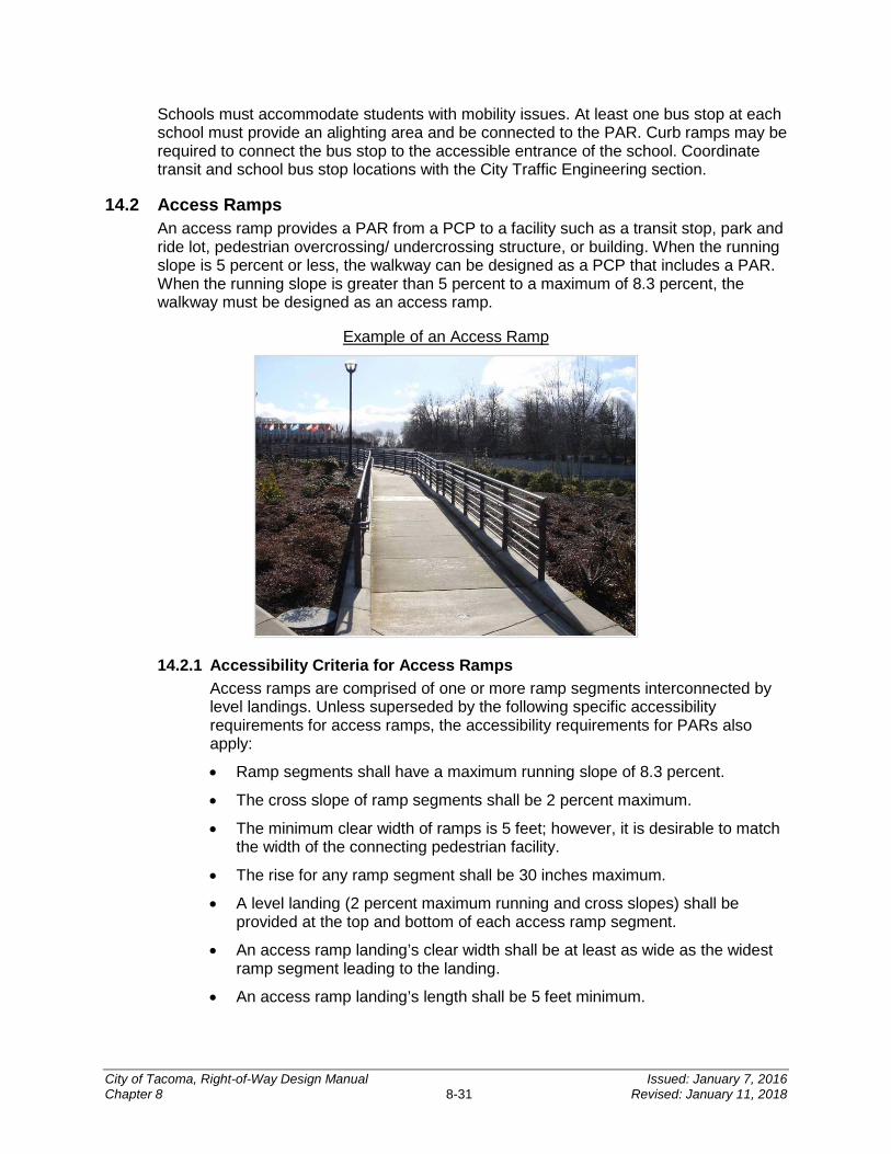
Schools must accommodate students with mobility issues. At least one bus stop at each school must provide an alighting area and be connected to the PAR. Curb ramps may be required to connect the bus stop to the accessible entrance of the school. Coordinate transit and school bus stop locations with the City Traffic Engineering section.
14.2 Access Ramps An access ramp provides a PAR from a PCP to a facility such as a transit stop, park and ride lot, pedestrian overcrossing/ undercrossing structure, or building. When the running slope is 5 percent or less, the walkway can be designed as a PCP that includes a PAR. When the running slope is greater than 5 percent to a maximum of 8.3 percent, the walkway must be designed as an access ramp.
Example of an Access Ramp
14.2.1 Accessibility Criteria for Access Ramps Access ramps are comprised of one or more ramp segments interconnected by level landings. Unless superseded by the following specific accessibility requirements for access ramps, the accessibility requirements for PARs also apply:
• Ramp segments shall have a maximum running slope of 8.3 percent.
• The cross slope of ramp segments shall be 2 percent maximum.
• The minimum clear width of ramps is 5 feet; however, it is desirable to match the width of the connecting pedestrian facility.
• The rise for any ramp segment shall be 30 inches maximum.
• A level landing (2 percent maximum running and cross slopes) shall be provided at the top and bottom of each access ramp segment.
• An access ramp landing’s clear width shall be at least as wide as the widest ramp segment leading to the landing.
• An access ramp landing’s length shall be 5 feet minimum.
City of Tacoma, Right-of-Way Design Manual Issued: January 7, 2016 Chapter 8 8-31 Revised: January 11, 2018
• Access ramps that change direction between ramp segments at landings shall have a level landing 5 feet minimum width by 5 feet minimum length.
• All access ramp segments with a rise greater than 6 inches shall have ADA compliant handrails (see Section 14.3 of this chapter for handrail accessibility criteria).
• Provide edge protection complying with one of the two following options on each side of access ramp segments:
The surface of the ramp segment and landing shall extend 12 inches minimum beyond the inside face of the handrail.
A curb or barrier shall be provided that does not allow the passage of a 4 inch diameter sphere, where any portion of the sphere is within 4 inches of the ramp/landing surface.
14.3 Guards and Handrails for Pedestrian Facilities Accessible handrails are required on stairs and also on access ramps that have a rise greater than 6 inches (see Section 14.2 of this chapter for access ramp accessibility criteria). A drop off/vertical grade separation that is 30 inches or greater adjacent to a pedestrian facility necessitates the need to protect pedestrians from falls and a more robust guard designed for fall protection shall be used. If the drop off/vertical grade separation is adjacent to either a stairway or an access ramp with a rise greater than 6 inches, then a guard/handrail combination that meets the requirements for both accessibility and fall protection must be used.
14.3.1 Fall Protection Guards Guards designed for fall protection alone are typically placed adjacent to pedestrian facilities other than stairs or access ramps to prevent pedestrians or bicyclists from falls. The minimum railing height for pedestrian fall protection is 42 inches. For facilities where bicycle traffic is anticipated, such as on a grade separation structure on a shared-use facility, the minimum railing height for bicyclist fall protection is 54 inches (see CHAPTER 10).
14.3.2 Accessible Fall Protection Railing When fall protection is needed adjacent to stairs or an access ramp that has a rise greater than 6 inches, then a combined railing system that meets both the accessibility criteria for handrail outlined in Section 14.3.4 and the requirements for fall protection must be used. The minimum railing height for pedestrian fall protection is 42 inches. For facilities where bicycle traffic is anticipated, such as on the approach to a grade separation structure on a shared-use facility, the minimum railing height for bicyclist fall protection is 54 inches (see CHAPTER 10).
14.3.3 Accessible Handrail Accessible handrail meeting the accessibility criteria that is not designed to provide fall protection is to be used adjacent to stairs or access ramps that have a rise greater than 6 inches at locations where robust fall protection is not needed.
City of Tacoma, Right-of-Way Design Manual Issued: January 7, 2016 Chapter 8 8-32 Revised: January 11, 2018

14.3.4 Accessibility Criteria for Handrail The following accessibility criteria apply to all handrail installations provided at stairs and access ramps that have a rise greater than 6 inches:
• Height
The top of handrail gripping surfaces shall be 34 inches minimum and 38 inches maximum vertically above walking surfaces, stair nosings, and ramp surfaces.
The mounting height of the handrail shall also be at a consistent height.
• Gripping Surface
Clearance between handrail gripping surfaces and adjacent surfaces shall be 1.5 inches minimum.
Handrail gripping surfaces shall be continuous along their length and shall not be obstructed along their tops or sides.
The bottoms of handrail gripping surfaces shall not be obstructed for more than 20 percent of their length.
Where provided, horizontal projections shall be located 1.5 inches minimum below the bottom of the handrail gripping surface.
Handrail gripping surfaces with a circular cross section shall have an outside diameter between 1.25 inches minimum and 2 inches maximum.
Handrail gripping surfaces with a noncircular cross section shall have a perimeter dimension between 4 inches minimum and 6.25 inches maximum, and a cross section dimension of 2.25 inches maximum.
Handrail gripping surfaces and the surfaces adjacent to them shall be free of sharp or abrasive elements and shall have rounded edges.
Handrails shall not rotate in their fittings.
• Placement and Continuity
Handrails shall be provided on both sides of access ramps and stairs. Handrails shall be continuous within the full length of each access ramp
run or stair flight. Inside handrails on switchback or dogleg access ramps and stairs shall
be continuous between runs or flights.
• Extensions
Access ramp handrails shall extend horizontally above the landing for 12 inches minimum beyond the top and bottom of ramp runs.
At the top of a stair flight, handrails shall extend horizontally above the landing for 12 inches minimum beginning directly above the first riser nosing.
At the bottom of a stair flight, handrails shall extend at the slope of the stair flight for a horizontal distance at least equal to one tread depth beyond the last riser nosing.
Handrail extensions shall return to a wall, guard, or the landing surface, or shall be continuous to the handrail of an adjacent access ramp run or stair flight.
City of Tacoma, Right-of-Way Design Manual Issued: January 7, 2016 Chapter 8 8-33 Revised: January 11, 2018
Handrail extensions shall not be required for continuous handrails at the inside turn of switchback or dogleg access ramps or stairs.
14.4 Other Pedestrian Facilities, Features, and Elements The information discussed above covers the accessibility criteria for the most commonly encountered pedestrian design elements in the public ROW. However, there are ADA requirements that apply to any feature or element for pedestrian use, such as doorways, elevators, stairs, call boxes, and drinking fountains. For accessibility criteria for less commonly encountered pedestrian design elements, consult with the ADA Coordinator and the applicable federal guidance document(s).
SECTION 15 Illumination and Signing Illumination of transit stops, pedestrian crossings and other facilities is an important design consideration because lighting has a major impact on a pedestrian’s safety and sense of security. Illumination provided solely for vehicular traffic is not always effective in lighting parallel walkways for pedestrians. Consider pedestrian level (mounted at a lower level) lighting for PCPs, intersections, and other pedestrian crossing areas. Refer to CHAPTER 5 for illumination design guidance and requirements.
SECTION 16 Work Zone Pedestrian Accommodation While Title II of the ADA requires that a public entity maintain its pedestrian facilities in operable working condition, including maintenance of their accessibility features, construction and maintenance activities often temporarily disrupt these facilities. When this occurs, provide access and mobility for pedestrians through and around work zones. Temporary traffic control plans that include alternate PARs must be approved prior to the start of construction. Additional Traffic Control Plans must be resubmitted and approved whenever there are changes or disruptions to the PAR.
Detailed guidance on work zone pedestrian accommodation can be found in the City of Tacoma Alternate Pedestrian Route Quick Reference Guide, Checklist for Pedestrian Access through Construction Zones, City of Tacoma Traffic Control Handbook, WSDOT Field Guide for Accessible Public Rights of Way, and the MUTCD.
Some work zone considerations include:
• Separate pedestrians from conflicts with work zone equipment and operations.
• Separate pedestrians from traffic moving through or around the work zone.
• Provide pedestrians with alternate routes that have accessible and convenient travel paths that duplicate, as closely as feasible, the characteristics of the existing pedestrian facilities.
Provide walkways that are clearly marked and pedestrian barriers that are continuous, rigid, and detectable to vision-impaired persons who navigate with a cane. Also, keep:
• The pedestrian head space clear.
• Walkways free from pedestrian hazards such as holes, debris, and abrupt changes in grade or terrain.
City of Tacoma, Right-of-Way Design Manual Issued: January 7, 2016 Chapter 8 8-34 Revised: January 11, 2018
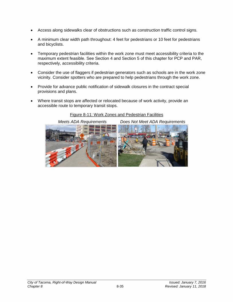
• Access along sidewalks clear of obstructions such as construction traffic control signs.
• A minimum clear width path throughout: 4 feet for pedestrians or 10 feet for pedestrians and bicyclists.
• Temporary pedestrian facilities within the work zone must meet accessibility criteria to the maximum extent feasible. See Section 4 and Section 5 of this chapter for PCP and PAR, respectively, accessibility criteria.
• Consider the use of flaggers if pedestrian generators such as schools are in the work zone vicinity. Consider spotters who are prepared to help pedestrians through the work zone.
• Provide for advance public notification of sidewalk closures in the contract special provisions and plans.
• Where transit stops are affected or relocated because of work activity, provide an accessible route to temporary transit stops.
Figure 8-11: Work Zones and Pedestrian Facilities
Meets ADA Requirements Does Not Meet ADA Requirements
City of Tacoma, Right-of-Way Design Manual Issued: January 7, 2016 Chapter 8 8-35 Revised: January 11, 2018
CHAPTER 9TREE AND VEGETATION MANAGEMENT
INTRODUCTION ..................................................................................... 9-2
SECTION 1 Applicability ................................................................... 9-2 1.1 Regulated Trees .......................................................................................................9-2 1.2 Required Practices ...................................................................................................9-2 1.3 Recommended Practices ..........................................................................................9-3
SECTION 2 Tree Planting, Removal and Replacement ................... 9-3 2.1 Permitting .................................................................................................................9-3
2.1.1 Exceptions ........................................................................................................... 9-3 2.2 Tree Planting ............................................................................................................9-3
2.2.1 Permit Application ................................................................................................ 9-3 2.2.2 Tree Clearances .................................................................................................. 9-4 2.2.3 Line of Sight ......................................................................................................... 9-4 2.2.4 Alternate Specifications ....................................................................................... 9-4 2.2.5 Planting Strip Treatments .................................................................................... 9-5 2.2.6 Planting Materials ................................................................................................ 9-6
2.3 Tree Pruning (Trimming) ...........................................................................................9-6 2.3.1 Permit Application ................................................................................................ 9-6 2.3.2 Traffic Control ...................................................................................................... 9-7
2.4 Tree Removal ...........................................................................................................9-7 2.4.1 Permit Application ................................................................................................ 9-7 2.4.2 Traffic Control ...................................................................................................... 9-8 2.4.3 Tree Replacement ............................................................................................... 9-8
SECTION 3 Tree Protection During Construction ........................... 9-8
9
City of Tacoma, Right-of-Way Design Manual Issued: January 7, 2016 Chapter 9 9-1 Revised: January 11, 2018
INTRODUCTION
This chapter establishes required procedures and standards for landscaping within the ROW. The standards and procedures contained herein must be followed to ensure that plants provide the needed benefits while posing minimal conflicts with infrastructure, human health and safety.
The following resources are meant to accompany the requirements of this Manual:
• Urban Forest Manual
The Urban Forest Manual (UFM) is a technical guide created to facilitate the planning, design, installation and maintenance of landscaping within Tacoma. Volume 3 of the UFM provides guidance on planting that is required for new development and redevelopment, however, the minimum requirements presented in the UFM are in line with industry BMPs for landscaping. Specifically, the standards in the UFM which refer to the ROW shall be used when landscaping within the ROW.
• American National Standards Institute
All tree care work performed within the ROW shall be in compliance with American National Standards Institute (ANSI) A300 and Z133.1 practices. All plant material provided shall be in compliance with ANSI Z60.1 for Nursery Stock.
• Tacoma Municipal Code
Trees and landscaping within the ROW are discussed in several locations within TMC, including but not limited to TMC 9.18 Trees and Shrubs - Trimming and Removal, TMC 9.19 Trees and Shrubs - Planting, TMC 9.20 Trees and Shrubs - View Blockage, and TMC 13.06.502 Landscaping and Buffering Standards. All of these sections of TMC shall be adhered to in addition to the requirements set forth in this Manual.
SECTION 1 Applicability
1.1 Regulated Trees All trees within the ROW are considered regulated trees and are subject to the standards for management contained in this Manual. Per TMC 9.18 and 9.19, a Tree Work in the ROW Permit is required for the planting, pruning, or removal of any regulated tree.
1.2 Required Practices Required practices are to be implemented by the property owner, project applicant, contractor or designee, and are minimum standards for work undertaken on a regulated tree.
Required practices are reasonable measures consistent with BMPs in the landscape and tree care industry to protect public health, safety and welfare and to promote the health of trees as an environmental priority of the City.
City of Tacoma, Right-of-Way Design Manual Issued: January 7, 2016 Chapter 9 9-2 Revised: January 11, 2018
1.3 Recommended Practices Recommended practices are those which provide guidance to ensure that proactive measures implemented for the care of trees (supplemental watering, fertilization, mulching, treatment to discourage pests, etc.) are consistent with current industry standards, and City policies and procedures. Recommended practices are not required; however the City has discretionary authority to require recommended practices as a condition for approval of a project permitted by the City or as mitigation for damage to trees in the ROW.
SECTION 2 Tree Planting, Removal and Replacement
2.1 Permitting A regulated tree must be protected and preserved unless otherwise approved through a Tree Work in the ROW Permit, issued by the Planning and Development Services Department in advance. Tree work requiring a Tree Work in the ROW Permit includes all tree planting, pruning or removal activities on regulated trees.
Tree Work in the ROW Permit applications may be obtained online or through the Planning and Development Services Permit Intake Center located on the third floor of the Tacoma Municipal Building, 747 Market Street, Tacoma, WA 98402.
2.1.1 Exceptions Exceptions to this requirement are made for emergency removals necessary to mitigate a threat to public health and safety of welfare. In those instances the City must be notified of the hazardous conditions warranting the removal of the tree immediately (prior to removal), and a Tree Work in the ROW Permit must be obtained prior or within 24 hours following the removal.
A hazardous tree is that which has been designated as a hazard by an International Society of Arboriculture (ISA) Certified Arborist, who has obtained an ISA Tree Risk Assessor Course and Exam certification or Tree Risk Assessment Qualification. Tree hazards include dead or dying trees, dead parts of live trees, or unstable live trees (due to structural defects or other factors) that are within striking distance of people or property (a target). Hazard trees are those which have the potential to cause property damage, personal injury or fatality in the event of a failure.
2.2 Tree Planting All trees planted within the ROW shall comply with TMC 9.19 and TMC 13.06.502 as well as the standards set forth in the UFM, Volume 3, Chapter 4.2 General Landscaping Standards. In addition to these standards contained in TMC and the UFM, the following process and standards shall apply.
2.2.1 Permit Application Planting trees within the ROW when not otherwise permitted through a ROW Construction/Work Order Permit requires a separate Tree Work in the ROW Permit. A Tree Work in the ROW Permit will be granted if the adjacent property owner can sufficiently demonstrate that the standards of this section can be met.
City of Tacoma, Right-of-Way Design Manual Issued: January 7, 2016 Chapter 9 9-3 Revised: January 11, 2018
The application must include a sketch showing all of the following:
• Existing site features:
Location(s) of all buildings; Streets; Sidewalks; Known utility locations (overhead and underground); and Existing trees.
• Pertinent proposed tree planting information:
Proposed number of trees; Proposed planting spaces; and Tree species identification.
In addition, the applicant must select a tree from the City of Tacoma Approved Tree List (see UFM, Volume 3, Appendix 7). If an applicant proposes an alternative tree that is not listed on the Approved Tree List, information on the growing characteristics of the tree from a published source such as a nursery “cut sheet” must accompany the application.
2.2.2 Tree Clearances Standard clearances for trees in the ROW are as defined in UFM and in the City Standard Plan LS-02. There are limited exceptions allowed based on site specific review and approval by the City. These exception requests must be submitted to the City with the Work Order or Tree Work in the ROW Permit submittal, and will be reviewed based on demonstration of mitigating potential impacts to public infrastructure.
2.2.3 Line of Sight For adequate line of sight, street trees must be placed no closer than 25 feet from intersections; measurement must be taken at the extension of the outside face of curb. Shrub and groundcover plants located in planting strips within 30 feet of a street intersection must be selected for compatibility with sight distance requirements, limiting height to 36 inches. Refer to the Intersection Sight Distance section of the Intersection chapter of the latest edition of the AASHTO Green Book on recommended sight distance for intersection control conditions.
2.2.4 Alternate Specifications The Planning and Development Services Department will review proposed alternatives to the standards contained here and in the UFM. These alternate specifications must be submitted to the City with the ROW Construction/Work Order Permit or Tree Work in the ROW Permit submittal. Approvals may be granted as long as it is demonstrated that these alternatives are designed to support street tree installations for optimum tree health and longevity and compatibility with other infrastructure in the ROW. Examples of these alternative specifications include engineered or structural soil mixes, structural support systems, modular structural pavement systems (Silvacells), etc.
City of Tacoma, Right-of-Way Design Manual Issued: January 7, 2016 Chapter 9 9-4 Revised: January 11, 2018
2.2.5 Planting Strip Treatments The following is a list of typical planting strip treatments and associated requirements.
• Pedestrian Crossings – Treatments in planting strips to accommodate for pedestrian crossings should be considered if the project site has on-street parking and is located within a mixed-use center, commercial area or other locations that experience heavy pedestrian traffic. Guidance on standards for pedestrian crossings are located in the MoMAP.
• Vegetation – Preapproved options for planting areas include:
Planting: groundcovers, perennials and shrubs with mulch covering exposed soil area. Plants (other than trees) must be less than 3 feet in mature height if planted within 30 feet of a street intersection in the ROW.
Mulch: organic wood chip mulch and/or permeable inorganic mulch. Finished grade after mulch application shall be a minimum of 1 inch below the adjacent pavement surface or curb.
• Low Impact Development/GSI – The SWMM outlines requirements for stormwater mitigation including low impact development. The type of mitigation is based upon the impacts created by a new or redevelopment project. Projects with 7,000 square feet or more of land disturbing activities or 2,000 square feet or more of new plus replaced hard surfaces will need to refer to the SWMM to determine if low impact development will be a requirement for their project. Information contained in the SWMM may also be helpful for retrofit type projects.
Low impact development or GSI in the ROW can include retained and/or new street trees required as a City condition for new development per TMC 13.06.502 as well as other low impact development BMPs including bioretention areas, dispersion, or infiltration. All proposed stormwater facilities within the ROW will need to acquire a permit prior to construction in the ROW. Please contact the Planning and Development Services Department for permit requirements. For more information on GSI requirements, see CHAPTER 4.
• Paving and Permanent Constructed Improvements in the ROW – Per TMC 10.14, paving the outer planting strip requires special permission from the Director of Public Works. In addition, a Street Occupancy Permit is required from the City to install any other permanent improvements in the planting strip, to include irrigation and raised planter boxes. Contact the Planning and Development Services Department to apply for a Street Occupancy Permit to construct permanent improvements within the planting strip.
• Raised Planter Boxes – Raised planter boxes may be installed in the ROW, provided that a Street Occupancy Permit is obtained prior to doing so. All planter boxes shall be no more than 24 inches in height, and shall have a minimum setback of 2 feet from the curb and from the edge of sidewalk. They may be no longer than 40 feet in length, and must provide a minimum of 3 feet of unimpeded clearance at each end to provide pedestrian access between the sidewalk and curbside vehicles.
City of Tacoma, Right-of-Way Design Manual Issued: January 7, 2016 Chapter 9 9-5 Revised: January 11, 2018
Plant height in a raised planter box shall be measured from the surrounding ground level, not the ground level within the planter box.
2.2.6 Planting Materials
• Stakes and Ties – Tree stakes shall be treated 2 inch diameter lodgepole pine or equivalent, two stakes per tree. Ties shall be one inch wide rubber tree ties or equivalent, such as V.I.T. Products, tree supports, twist brace, fabric-reinforced rubber (0.375 inch minimum). Refer to City Standard Plan LS-01.
• Root Barrier – Root barrier (18 inch depth by 10 foot length) is required along the edge of roadways, sidewalks, curbs and driveways for all trees whose trunks are within 4 feet of the paved edge. Root barriers shall be an injection molded or extruded modular component made of high density polypropylene plastic. Refer to City Standard Plan LS-01.
• Arborist Wood Chip Mulch – Mulch shall be coarse untreated wood chips 0.5 to 6 inch in size, free of weeds, weed seeds and invasive plant parts. Mulch shall be installed to provide a 3 inch depth over a minimum area twice the diameter of the root ball. The mulch should be kept at least two inches away from the trunk. Refer to City Standard Plan LS-01.
• Tree Grates – Tree grates are allowed but not recommended by the City as a tree pit treatment based on the maintenance necessary to ensure a surface flush with adjacent sidewalk for public safety, and routine expansion for clearance from the trunk of a tree as it grows. If proposed, all tree grates must meet the requirements set forth for ADA compliance, including surfacing (slip resistance) and maximum opening size. Refer to CHAPTER 8, Section 5 for the requirements regarding tree grates.
2.3 Tree Pruning (Trimming) A Tree Work in the ROW Permit is required for all proposed pruning activities on regulated trees, and shall comply with TMC 9.18 and TMC 13.06.502 as well as the standards set forth in the UFM.
Pruning (trimming) is defined as the removal of plant parts, dead or alive, in a systematic manner as to not damage other parts of the plant. Pruning is most often performed for the purposes of improving plant health, structure, aesthetics or safety of the vegetation. Pruning must be performed according to ANSI A300 guidelines by an individual or company with a valid Washington State contractor’s license, City license and current bonding. In addition to the standards contained in TMC and those contained in the UFM, the following process and standards shall apply.
2.3.1 Permit Application A Tree Work in the ROW Permit may be granted provided that the adjacent property owner (applicant) can sufficiently demonstrate the reasoning for pruning the regulated tree, and that the public benefit provided by the tree’s foliage is outweighed by significant tree defects or threats to public safety.
City of Tacoma, Right-of-Way Design Manual Issued: January 7, 2016 Chapter 9 9-6 Revised: January 11, 2018
All Tree Work in the ROW Permit applications for pruning must include the following:
• Location of the proposed tree;
• Photograph of the vegetation;
• A statement of the problem (objective) to be addressed through the proposed pruning;
• Proposed solution; and
• The approximate percentage of the tree’s crown which is proposed to be removed.
Note: No more than 25 percent of the trees foliage may be removed in any pruning event. Topping of regulated trees is explicitly prohibited.
Preapproved objectives for pruning include:
• Removal of dead, significantly damaged or diseased tree parts; and/or,
• Pruning to maintain required tree clearances over sidewalks (8 feet) and roadways (14 feet).
2.3.2 Traffic Control The property owner or tree care provider must provide appropriate traffic control during all regulated tree work operations. Traffic Control Plans are needed for activities in or near the ROW where equipment, materials, or people entering or using the street and sidewalk areas could create safety hazards or traffic congestion. Traffic control plans must be submitted with the Tree Work in the ROW Permit and must comply with the City of Tacoma Traffic Control Handbook.
2.4 Tree Removal A Tree Work in the ROW Permit is required for all regulated tree removals, and shall comply with TMC 9.18 and 13.06.502, as well as the standards set forth in the UFM. In addition to these standards contained in TMC and the UFM, the following process and standards shall apply.
2.4.1 Permit Application A Tree Work in the ROW Permit may be granted if the adjacent property owner (applicant) can sufficiently demonstrate that the public benefit provided by the tree is outweighed by significant tree defects. Trees that are determined to be dead, dying, “hazard trees,” or “inappropriate species” are automatic candidates for removal. The following factors shall not be considered as criteria for removal of a street tree:
• Obstruction of view;
• Potential future damage to public infrastructure or private property, if that damage can be avoided by root pruning, root barriers or other management strategies;
• The cost of routine tree maintenance (pruning, watering, fertilizing, etc.);
City of Tacoma, Right-of-Way Design Manual Issued: January 7, 2016 Chapter 9 9-7 Revised: January 11, 2018

• Normal maintenance activities such as the raking of leaves and flowers and cleaning of gutters; or
• Hazards that can be controlled or eliminated through appropriate pruning or maintenance.
If tree removal is permitted, all stumps and surface roots of trees shall be ground or removed to a point at least 18 inches below the top of the adjacent curb/sidewalk or proposed grade.
2.4.2 Traffic Control The property owner or tree care provider must provide appropriate traffic control during all regulated tree work operations. Traffic Control Plans are needed for activities in or near the ROW where equipment, materials, or people entering or using the street and sidewalk areas could create safety hazards or traffic congestion. Traffic Control Plans must be submitted with the Tree Work in the ROW Permit and must comply with the City of Tacoma Traffic Control Handbook.
2.4.3 Tree Replacement The City requires tree replacement as a standard condition for issuance of a permit for removal of a tree if the tree is required for the development as specified in TMC 13.06.502.
SECTION 3 Tree Protection During Construction
The UFM contains the mandatory actions in addition to those contained in TMC 9.18.030 for protection of existing trees during construction activities, and permitted construction activities around existing trees.
Per the TMC, in all instances where construction activities are to occur around existing trees which otherwise have not been permitted to be removed, to include the alteration of any building or portion thereof, proper tree protection guards are required to be installed prior to the commencement of construction. Refer to City Standard Plans LS-08, LS-09, LS-10 and LS-11 for permissible tree protection guards and methods.
For more information on tree protection during construction, the following resources are suggested.
• Tree Protection on Construction and Development Sites, A Best Management Practices Guidebook for the Pacific Northwest
• ANSI A300, Part 5, Construction Management Standard
• International Society of Arboriculture BMPs, Managing Trees During Construction
City of Tacoma, Right-of-Way Design Manual Issued: January 7, 2016 Chapter 9 9-8 Revised: January 11, 2018
CHAPTER 10SHARED-USE PATHS
INTRODUCTION ................................................................................... 10-3
SECTION 1 References ................................................................... 10-3 1.1 Federal/State Laws and Codes ............................................................................... 10-3 1.2 Design Standards and Guidance ............................................................................ 10-3
SECTION 2 Shared-Use Path Design – The Basics ...................... 10-4 2.1 Design Speed ......................................................................................................... 10-4
SECTION 3 Shared-Use Path Design Widths ................................ 10-5 3.1 Deviations from Standard Path Width ..................................................................... 10-6
3.1.1 Existing Shared-Use Paths – Considerations ..................................................... 10-6
SECTION 4 Slope ............................................................................ 10-6 4.1 Cross Slope of the Path and Shoulder .................................................................... 10-6 4.2 Side Slopes and Pedestrian Rail ............................................................................ 10-6
SECTION 5 Clearances ................................................................... 10-8
SECTION 6 Buffers .......................................................................... 10-8
SECTION 7 Running Slopes, Landings, and Rest Areas .............. 10-9 7.1 Running Slopes ...................................................................................................... 10-9 7.2 Landings ................................................................................................................. 10-9 7.3 Rest Areas ............................................................................................................ 10-10
SECTION 8 Pavement Structural Section .................................... 10-10
SECTION 9 Stopping Sight Distance for Shared-Use Paths ...... 10-11 9.1 Stopping Sight Distance on Crest Vertical Curves ................................................ 10-11 9.2 Stopping Sight Distance on Horizontal Curves...................................................... 10-11
SECTION 10 Intersections and Crossing Design .......................... 10-11 10.1 Path Intersects with Roadways ............................................................................. 10-11 10.2 Midblock Crossings .............................................................................................. 10-11 10.3 Adjacent Paths ..................................................................................................... 10-12 10.4 Additional Roadway/Path Intersection Design Considerations .............................. 10-13 10.5 At Grade Railroad Crossings ................................................................................ 10-13
SECTION 11 Grade Separated Crossings...................................... 10-14
10
City of Tacoma, Right-of-Way Design Manual Issued: January 7, 2016 Chapter 10 10-1 Revised: January 11, 2018
SECTION 12 Signing, Pavement Markings and Illumination ........ 10-15 12.1 Mileage Markers ................................................................................................... 10-15
SECTION 13 Restricted Use Controls ............................................ 10-15 13.1 Fencing................................................................................................................. 10-15 13.2 Restriction of Motor Vehicles ................................................................................ 10-16
13.2.1 Landscaped Islands ..................................................................................... 10-16 13.2.2 Bollard Considerations ................................................................................. 10-16
City of Tacoma, Right-of-Way Design Manual Issued: January 7, 2016 Chapter 10 10-2 Revised: January 11, 2018
INTRODUCTION
This chapter provides guidance on how to achieve the appropriate separation, amenities, and design tools to ensure that the Shared-Use Path is designed consistent with the context of its location and intended users. Refer to CHAPTER 4 for planning documents outlining the bicycle network. Shared-use paths are designed for both transportation and recreation purposes and are used by pedestrians, bicyclists, skaters, and other users.
The City’s planning efforts include a network of shared-use paths that internally connect City neighborhoods and provide connections to neighboring jurisdictions and the regional trail network. The goal is to ensure that the design and construction of shared-use paths are consistent with the most current regulations, guidelines, and community plans. Therefore, applicants can be expected to have their shared-use path designs reviewed by a City interdisciplinary team [currently named the Design Integration Review Team (DIRT)] and/or stakeholder advisory group to the City to help ensure they are consistent, well-suited designs and user amenities. An applicant, for purposes of this chapter, includes design engineers, project managers, developers, property owners, or other project representatives intending to develop a shared-use path.
The information herein is resourced from the various state and federal laws/codes/and guidance report/documents. The user of this chapter is advised that the referenced materials reflect the needs and desire of the City, its citizens, and stakeholders. Figures are provided throughout this chapter to illustrate possible design solutions and flexibility as long as the corresponding laws, regulations, and standards are not compromised.
SECTION 1 References
1.1 Federal/State Laws and Codes Americans with Disabilities Act of 1990 (ADA)
ADA (28 CFR Part 35, as revised September 15, 2010)
23 CFR Part 652, Pedestrian and Bicycle Accommodations and Projects
49 CFR Part 27, Nondiscrimination on the Basis of Disability in Programs or Activities Receiving Federal Financial Assistance (Section 504 of the Rehabilitation Act of 1973 implementing regulations)
1.2 Design Standards and Guidance Federal and State:
• Rails-to-Trails Conservancy Trail-Building Toolbox with informative chapters ranging from bridges, crossings, accessibility and user types.
• WSDOT Design Manual - Chapter 1515 - Shared-use Paths
• Revised Draft Guidelines for Accessible Public Rights-of-Way (PROWAG). The current best practices for evaluation and design of pedestrian facilities in the public right of way .
• Manual on Uniform Traffic Control Devices for Streets and Highways, USDOT, FHWA, as adopted and modified by Chapter 468-95 WAC (MUTCD).
City of Tacoma, Right-of-Way Design Manual Issued: January 7, 2016 Chapter 10 10-3 Revised: January 11, 2018
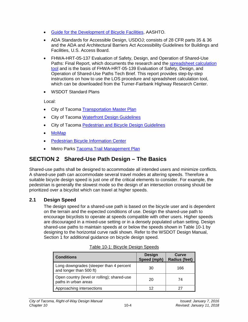
• Guide for the Development of Bicycle Facilities, AASHTO.
• ADA Standards for Accessible Design, USDOJ; consists of 28 CFR parts 35 & 36 and the ADA and Architectural Barriers Act Accessibility Guidelines for Buildings and Facilities, U.S. Access Board.
• FHWA-HRT-05-137 Evaluation of Safety, Design, and Operation of Shared-Use Paths: Final Report, which documents the research and the spreadsheet calculation tool and is the basis of FHWA-HRT-05-139 Evaluation of Safety, Design, and Operation of Shared-Use Paths Tech Brief. This report provides step-by-step instructions on how to use the LOS procedure and spreadsheet calculation tool, which can be downloaded from the Turner-Fairbank Highway Research Center.
• WSDOT Standard Plans
Local:
• City of Tacoma Transportation Master Plan
• City of Tacoma Waterfront Design Guidelines
• City of Tacoma Pedestrian and Bicycle Design Guidelines
• MoMap
• Pedestrian Bicycle Information Center
• Metro Parks Tacoma Trail Management Plan
SECTION 2 Shared-Use Path Design – The Basics
Shared-use paths shall be designed to accommodate all intended users and minimize conflicts. A shared-use path can accommodate several travel modes at altering speeds. Therefore a suitable bicycle design speed is just one of the critical elements to consider. For example, the pedestrian is generally the slowest mode so the design of an intersection crossing should be prioritized over a bicyclist which can travel at higher speeds.
2.1 Design Speed The design speed for a shared-use path is based on the bicycle user and is dependent on the terrain and the expected conditions of use. Design the shared-use path to encourage bicyclists to operate at speeds compatible with other users. Higher speeds are discouraged in a mixed-use setting or in a densely populated urban setting. Design shared-use paths to maintain speeds at or below the speeds shown in Table 10-1 by designing to the horizontal curve radii shown. Refer to the WSDOT Design Manual, Section 1 for additional guidance on bicycle design speed.
Table 10-1: Bicycle Design Speeds
Conditions Design Speed (mph)
Curve Radius (feet)
Long downgrades (steeper than 4 percent and longer than 500 ft) 30 166
Open country (level or rolling); shared-use paths in urban areas 20 74
Approaching intersections 12 27
City of Tacoma, Right-of-Way Design Manual Issued: January 7, 2016 Chapter 10 10-4 Revised: January 11, 2018
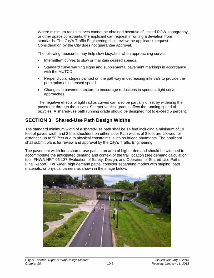
Where minimum radius curves cannot be obtained because of limited ROW, topography, or other space constraints, the applicant can request in writing a deviation from standards. The City’s Traffic Engineering shall review the applicant’s request. Consideration by the City does not guarantee approval.
The following measures may help slow bicyclists when approaching curves:
• Intermittent curves to slow or maintain desired speeds.
• Standard curve warning signs and supplemental pavement markings in accordance with the MUTCD.
• Perpendicular stripes painted on the pathway in decreasing intervals to provide the perception of increased speed.
• Changes in pavement texture to encourage reductions in speed at tight curve approaches.
The negative effects of tight radius curves can also be partially offset by widening the pavement through the curves. Steeper vertical grades affect the running speed of bicycles. A shared-use path running grade should be designed not to exceed 5 percent.
SECTION 3 Shared-Use Path Design Widths
The standard minimum width of a shared-use path shall be 14 feet including a minimum of 10 feet of paved width and 2 foot shoulders on either side. Path widths of 8 feet are allowed for distances up to 50 feet due to physical constraints, such as bridge abutments. The applicant shall submit plans for review and approval by the City’s Traffic Engineering.
The pavement width for a shared-use path in an area of higher demand should be widened to accommodate the anticipated demand and context of the trail location (see demand calculation tool, FHWA-HRT-05-137 Evaluation of Safety, Design, and Operation of Shared-Use Paths: Final Report). For wider, high demand paths, consider separating modes with striping, path materials, or physical barriers as shown in the image below.
City of Tacoma, Right-of-Way Design Manual Issued: January 7, 2016 Chapter 10 10-5 Revised: January 11, 2018
3.1 Deviations from Standard Path Width The applicant can request in writing a deviation from standard path width. Traffic Engineering shall review the applicant’s request, which may include considerations such as:
• Exclusive use by one mode.
• Horizontal and vertical alignments provide frequent, well-designed passing and resting opportunities.
• Connects to a neighborhood for a short distance.
Consideration by the City does not guarantee approval. Should the request for deviation be approved by the City, the applicant shall be responsible for all signing and pavement markings for such conditions. Applicant shall use the MUTCD to develop a plan for review and approval by the City.
3.1.1 Existing Shared-Use Paths – Considerations When an existing shared-use path does not meet current standards, the applicant shall be prepared to justify the deviation from current shared-use path standards. The applicant can request in writing a deviation from standards. Traffic Engineering shall review the applicant’s request. Consideration by the City does not guarantee approval.
SECTION 4 Slope
4.1 Cross Slope of the Path and Shoulder The cross slope on a paved shared-use path is 2 percent maximum. The cross slope of the shoulder cannot exceed 6:1. For drainage purposes, the entire section including the shoulders must transition through the curves. To avoid pavement crowning, it is desirable to design the pivot point on the outside edge of one shoulder. It is recommended to design the cross slope to less than the allowed maximum to allow for some tolerance during construction.
4.2 Side Slopes and Pedestrian Rail A gentle side slope along shared-use path is an important safety design feature. Therefore an embankment side slope of 6:1 or flatter is recommended.
For shared-use paths with side slopes steeper than 3:1, or where obstacles or waterways may exist, other options may be considered by the City at the request of the applicant, including:
• A minimum 5 foot separation from the edge of the pavement to the embankment edge. This can be accomplished by providing a 5 foot shoulder.
• A natural barrier such as dense shrubbery on the side slopes along the entire length of the trail where there is steep slope.
Where a shared-use path is adjacent to a vertical drop of 2 feet 6 inches or more, a pedestrian rail is needed.
• If the vertical drop is less than 2 feet 6 inches, a pedestrian rail, chain link fence, or 4 inch curb at the edge of the shared-use path may be installed to delineate the edge.
City of Tacoma, Right-of-Way Design Manual Issued: January 7, 2016 Chapter 10 10-6 Revised: January 11, 2018
Figure 10-1: Two-Way Shared-Use Path; Independent Alignment
Figure 10-2: Two-way Shared-Use Path: Attached to > 35mph Roadway
Notes: It is desirable for the cross slope to slope toward grass areas for drainage.
City of Tacoma, Right-of-Way Design Manual Issued: January 7, 2016 Chapter 10 10-7 Revised: January 11, 2018
Figure 10-3: Shared-Use Path Side Slopes and Railing
Example 1 (upper left): Embankment: Based on context, flatter slopes are desirable. Example 2 (upper right): Shoulder widening to 5 feet or more. Used with steeper fill slopes to provide clear space between the hinge point and path. Vegetation can also be used as a buffer on slopes. In lieu of 3 feet additional widening, consider a natural or physical barrier. Example 3 (lower left): Cut section with ditch. Consult with Traffic Engineering to determine for appropriate cut slopes. Example 4 (lower right): Railing used at drop off. Apply railing or fencing a minimum of 42 inches high when a drop off is present, such as along a retaining wall. Consult with Traffic Engineering to determine if shoulder along wall should be paved. Note: These drawings depict some common applications for various slope alternatives.
SECTION 5 Clearances
The minimum horizontal clearance from the edge of pavement to an obstruction (such as bridge piers or fence) is 2 feet. The minimum vertical clearance is 10 feet from the pavement surface to any overhead obstruction to accommodate maintenance vehicles and bicyclists.
SECTION 6 Buffers
A buffer area provided directly adjacent to the shared-use path to create separation and a planting area is a very desirable feature and may be required. The City recognizes that in a built urban setting a buffer area may not be feasible. Therefore at the written request of the applicant, Traffic Engineering will consider exceptions to buffers. The applicant is responsible to explain and/or present the circumstances warranting no or reduced buffer area. Should a buffer area be required, any vegetation provided there shall be of an approved species and maintained per City standards as defined in CHAPTER 9.
City of Tacoma, Right-of-Way Design Manual Issued: January 7, 2016 Chapter 10 10-8 Revised: January 11, 2018
SECTION 7 Running Slopes, Landings, and Rest Areas
7.1 Running Slopes The design of a running slope on a shared-use path is not to be greater than 5 percent.
An exception is a path parallel to street in the ROW where running slope can match the grade of the roadway.
7.2 Landings Landings are desirable on extended grades as they provide users with a level place to rest. Design vertical curves to transition from the grade to the landings. Figure 10-4 and Figure 10-5 show these features.
Design landings to:
• Permit users to stop periodically and rest.
• Not exceed maximum running slopes of 2 percent and cross slopes of 2 percent.
• Be in line and as wide as the shared-use path. Landings are to be at least 5 feet long.
• Avoid abrupt grade changes or angle points. Design transitions to landings using vertical curves
.
Figure 10-4: Shared-Use Path Landing Profile
City of Tacoma, Right-of-Way Design Manual Issued: January 7, 2016 Chapter 10 10-9 Revised: January 11, 2018

7.3 Rest Areas Rest areas may be provided adjacent to the shared-use path outside of the pathway travelled as shown in Figure 10-5.
Requirements for rest areas include:
• The maximum running slope and cross slope is 2 percent.
• The minimum landing size is 5 feet by 5 feet and it must be parallel and abutting the path.
• If features such as benches are provided, they must meet ADA requirements; consult with Traffic Engineering and ADA Coordinator for guidance.
Figure 10-5: Landing and Rest Area Example
Notes: Design landings at least 5 feet long and as wide as the shared-use path.
SECTION 8 Pavement Structural Section
Design the pavement structural section as recommended by Public Works Engineering, considering the quality of the subgrade and the anticipated loads on the path. Design loads are normally for maintenance and emergency vehicles, reference CHAPTER 4. Provide a firm, stable, slip-resistant pavement surface.
Use crushed rock or other suitable material for shoulder graded areas, reference WSDOT Standard Specifications Division 9. Consult with Public Works Engineering as needed. On bridges or in tunnels, it is a common practice to pave the entire shared-use path area, including shoulders across the structure.
The use of pervious asphalt or porous concrete should be considered when practicable. Consult the SWMM Volume 6 for design methodology and to help determine feasibility of permeable pavements. Standard Plan PD-01 has section designs for porous asphalt and pervious concrete.
City of Tacoma, Right-of-Way Design Manual Issued: January 7, 2016 Chapter 10 10-10 Revised: January 11, 2018
SECTION 9 Stopping Sight Distance for Shared-Use Paths
The distance needed to bring a shared-use path user to a complete stop is a function of the user’s perception and braking reaction times, the initial speed, the coefficient of friction between the wheels and the pavement, the braking ability of the user’s equipment, and the grade.
9.1 Stopping Sight Distance on Crest Vertical Curves Refer to the MUTCD for charts and tables for SSD on crest vertical curves.
9.2 Stopping Sight Distance on Horizontal Curves Refer to the MUTCD for charts and tables for SSD on horizontal curves.
SECTION 10 Intersections and Crossing Design
This section covers path/roadway intersections and grade separated crossings.
10.1 Path Intersects with Roadways The applicant shall be responsible to evaluate intersection controls including the need for traffic control devices at the path/roadway intersections by using MUTCD warrants and engineering judgment. Bicycles are considered vehicles in Washington State, and bicycle path traffic can be classified as vehicular traffic for MUTCD.
The applicant shall be responsible for evaluation of signal actuation mechanisms including the placement of manually operated accessible pedestrian pushbutton that comply with ADA requirements. Passive detection may be required in addition to the manually operated accessible pedestrian pushbutton, refer to CHAPTER 6 and CHAPTER 8.
The applicant shall be responsible for the evaluation of intersection signage including a list of signs by type, size, and location in accordance with the MUTCD.
The applicant shall be responsible for evaluation of approach treatments including the design of the shared-use path and roadway intersections with level grades and sight distances. Evaluate the need for advance warning signs and pavement markings that alert and direct path users that there is a crossing (refer to MUTCD).
The applicant shall be responsible for evaluation of sight distance including at minimum, provide SSD for both the roadway and the path at the crossing. Refer to MUTCD, CHAPTER 4, and the guidance set forth in this chapter on SSD for the roadway and for shared-use path respectively.
The applicant shall be responsible for evaluation of curb ramp widths including the design of curb ramps with a width equal to the shared-use path if possible. Curb ramps at path/roadway intersections must meet the requirements for curb ramps at a crosswalk. See CHAPTER 9 for additional guidance.
10.2 Midblock Crossings Clearly define who has the ROW and provide sight distance for all users at shared-use path and roadway intersections on the plan set.
City of Tacoma, Right-of-Way Design Manual Issued: January 7, 2016 Chapter 10 10-11 Revised: January 11, 2018
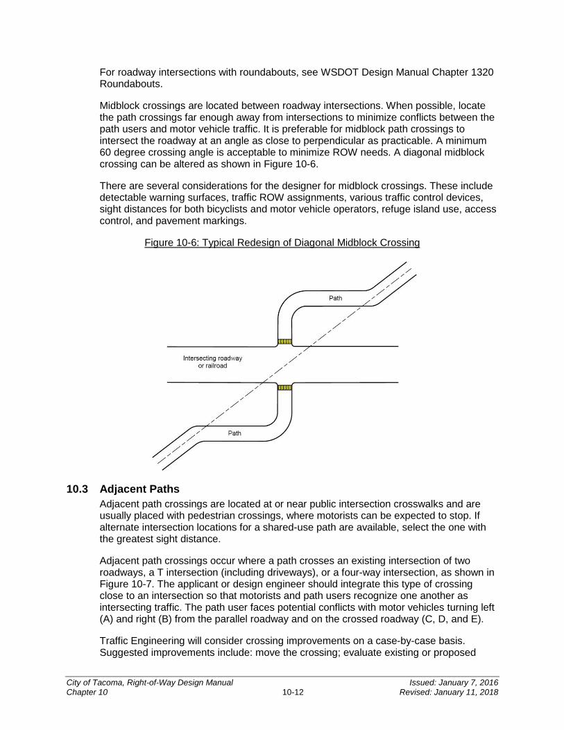
For roadway intersections with roundabouts, see WSDOT Design Manual Chapter 1320 Roundabouts.
Midblock crossings are located between roadway intersections. When possible, locate the path crossings far enough away from intersections to minimize conflicts between the path users and motor vehicle traffic. It is preferable for midblock path crossings to intersect the roadway at an angle as close to perpendicular as practicable. A minimum 60 degree crossing angle is acceptable to minimize ROW needs. A diagonal midblock crossing can be altered as shown in Figure 10-6.
There are several considerations for the designer for midblock crossings. These include detectable warning surfaces, traffic ROW assignments, various traffic control devices, sight distances for both bicyclists and motor vehicle operators, refuge island use, access control, and pavement markings.
Figure 10-6: Typical Redesign of Diagonal Midblock Crossing
10.3 Adjacent Paths Adjacent path crossings are located at or near public intersection crosswalks and are usually placed with pedestrian crossings, where motorists can be expected to stop. If alternate intersection locations for a shared-use path are available, select the one with the greatest sight distance.
Adjacent path crossings occur where a path crosses an existing intersection of two roadways, a T intersection (including driveways), or a four-way intersection, as shown in Figure 10-7. The applicant or design engineer should integrate this type of crossing close to an intersection so that motorists and path users recognize one another as intersecting traffic. The path user faces potential conflicts with motor vehicles turning left (A) and right (B) from the parallel roadway and on the crossed roadway (C, D, and E).
Traffic Engineering will consider crossing improvements on a case-by-case basis. Suggested improvements include: move the crossing; evaluate existing or proposed
City of Tacoma, Right-of-Way Design Manual Issued: January 7, 2016 Chapter 10 10-12 Revised: January 11, 2018
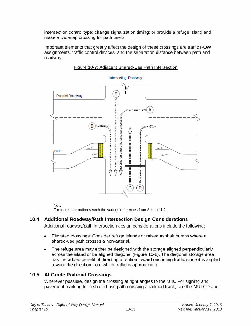
intersection control type; change signalization timing; or provide a refuge island and make a two-step crossing for path users.
Important elements that greatly affect the design of these crossings are traffic ROW assignments, traffic control devices, and the separation distance between path and roadway.
Figure 10-7: Adjacent Shared-Use Path Intersection
Note: For more information search the various references from Section 1.2
10.4 Additional Roadway/Path Intersection Design Considerations Additional roadway/path intersection design considerations include the following:
• Elevated crossings: Consider refuge islands or raised asphalt humps where a shared-use path crosses a non-arterial.
• The refuge area may either be designed with the storage aligned perpendicularly across the island or be aligned diagonal (Figure 10-8). The diagonal storage area has the added benefit of directing attention toward oncoming traffic since it is angled toward the direction from which traffic is approaching.
10.5 At Grade Railroad Crossings Wherever possible, design the crossing at right angles to the rails. For signing and pavement marking for a shared-use path crossing a railroad track, see the MUTCD and
City of Tacoma, Right-of-Way Design Manual Issued: January 7, 2016 Chapter 10 10-13 Revised: January 11, 2018
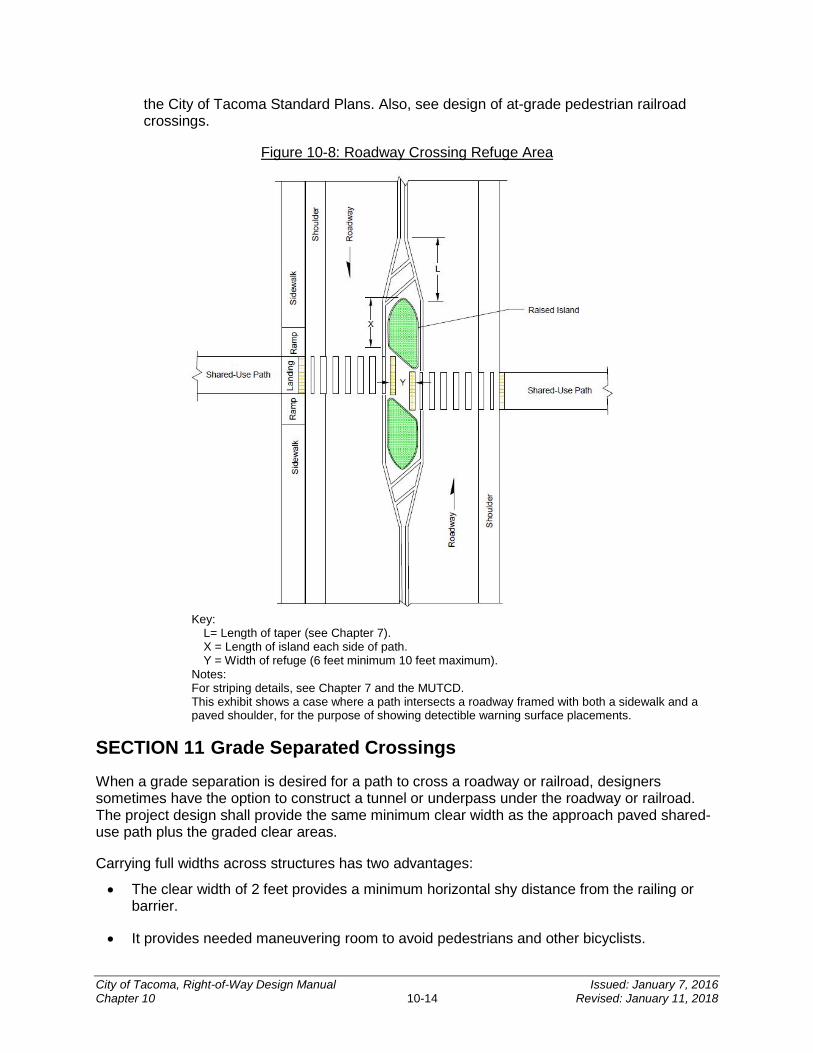
the City of Tacoma Standard Plans. Also, see design of at-grade pedestrian railroad crossings.
Figure 10-8: Roadway Crossing Refuge Area
Key:
L= Length of taper (see Chapter 7). X = Length of island each side of path. Y = Width of refuge (6 feet minimum 10 feet maximum).
Notes: For striping details, see Chapter 7 and the MUTCD. This exhibit shows a case where a path intersects a roadway framed with both a sidewalk and a paved shoulder, for the purpose of showing detectible warning surface placements.
SECTION 11 Grade Separated Crossings
When a grade separation is desired for a path to cross a roadway or railroad, designers sometimes have the option to construct a tunnel or underpass under the roadway or railroad. The project design shall provide the same minimum clear width as the approach paved shared-use path plus the graded clear areas.
Carrying full widths across structures has two advantages:
• The clear width of 2 feet provides a minimum horizontal shy distance from the railing or barrier.
• It provides needed maneuvering room to avoid pedestrians and other bicyclists.
City of Tacoma, Right-of-Way Design Manual Issued: January 7, 2016 Chapter 10 10-14 Revised: January 11, 2018
For undercrossings and tunnels, provide a minimum vertical clearance of 10 feet for path users from the path pavement to the structure above. This allows access by emergency, patrol, and maintenance vehicles on the shared-use path. Consult Public Works Engineering to verify that the planned path width meets their specifications.
If expansion joints are used in the shared-use path then they should be placed perpendicular to the path and have a maximum gap of 0.5 inch or be covered with a slip resistant plate. All joints must be ADA compliant, see CHAPTER 8.
If the shared-use path requires consideration of screening materials or railings, as identified in the above sections or to address neighborhood impacts, then consult with Public Works Engineering for such accommodation.
SECTION 12 Signing, Pavement Markings and Illumination
Refer to the MUTCD for guidance and directions regarding shared-use path signing (regulatory, warning, and way finding) and pavement markings. Wayfinding should be used on all trail corridors. The City is using the green and white MUTCD wayfinding as a standard to identify destinations of significance. Special districts may have individual signage styles, consult with Public Works Engineering.
For pavement markings around bollards and other obstructions see Section 13 of this chapter.
The level of illumination on a shared-use path is dependent on the amount of nighttime use expected and the nature of the area surrounding the facility. Illumination of the shared-use path should be considered for all segments not illuminated by arterial lighting or other sources. The City has an LED standard for pedestrian level illumination. Lighting may also require a cut-off shield to reduce light intrusion on to adjacent homes or properties. The applicant shall submit a lighting plan for review by Traffic Engineering that is consistent with guidance outlined in CHAPTER 5.
12.1 Mileage Markers Mileage markers should be used in corridors with a distinct beginning and ending in increments of 0.5 miles. The markers should measure distance starting from 0 in each direction. Markers should be inset and flush with the shared-use path, such as a tile or metal plate.
SECTION 13 Restricted Use Controls This section presents requirements on use of fencing and other treatments to separate motor vehicles from the shared-use path.
13.1 Fencing Fencing or other forms of controlling access are generally necessary to ensure compliance of intended use and safety along the path. Shared-use paths constructed as shown in Figure 10-8, likely require fencing. For guidance on fencing controls in the ROW, refer to WSDOT Design Manual, Division 5.
City of Tacoma, Right-of-Way Design Manual Issued: January 7, 2016 Chapter 10 10-15 Revised: January 11, 2018
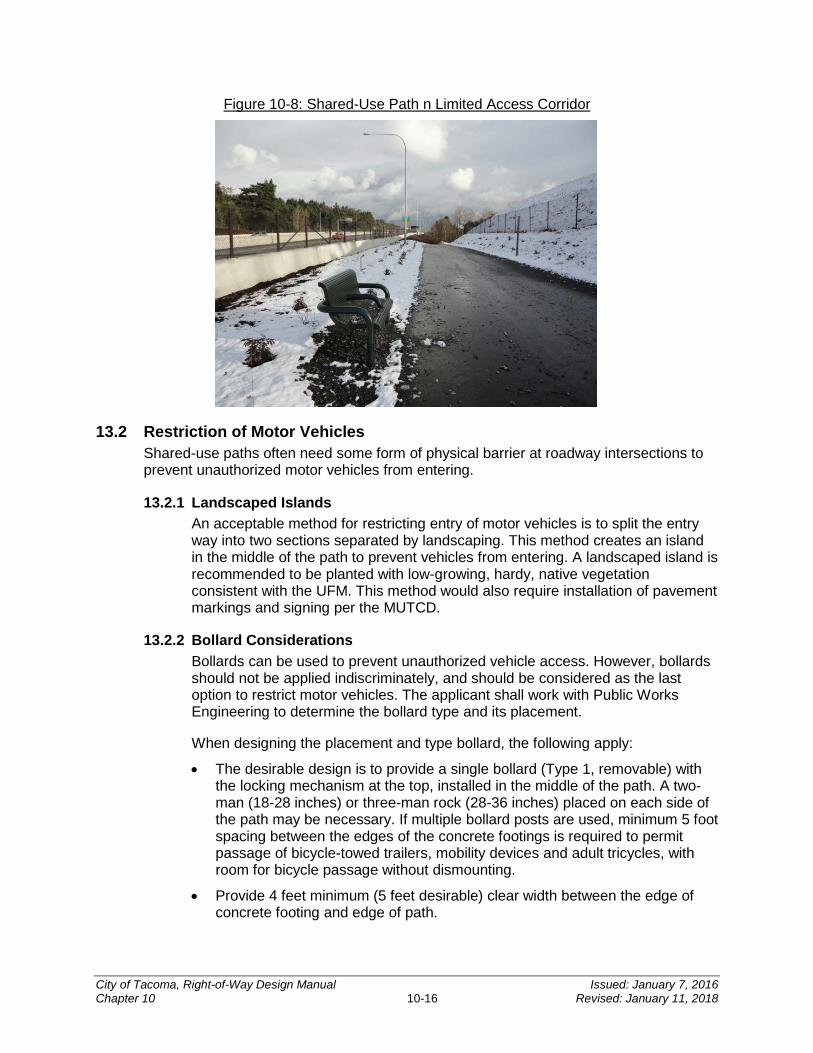
Figure 10-8: Shared-Use Path n Limited Access Corridor
13.2 Restriction of Motor Vehicles Shared-use paths often need some form of physical barrier at roadway intersections to prevent unauthorized motor vehicles from entering.
13.2.1 Landscaped Islands An acceptable method for restricting entry of motor vehicles is to split the entry way into two sections separated by landscaping. This method creates an island in the middle of the path to prevent vehicles from entering. A landscaped island is recommended to be planted with low-growing, hardy, native vegetation consistent with the UFM. This method would also require installation of pavement markings and signing per the MUTCD.
13.2.2 Bollard Considerations Bollards can be used to prevent unauthorized vehicle access. However, bollards should not be applied indiscriminately, and should be considered as the last option to restrict motor vehicles. The applicant shall work with Public Works Engineering to determine the bollard type and its placement.
When designing the placement and type bollard, the following apply:
• The desirable design is to provide a single bollard (Type 1, removable) with the locking mechanism at the top, installed in the middle of the path. A two- man (18-28 inches) or three-man rock (28-36 inches) placed on each side of the path may be necessary. If multiple bollard posts are used, minimum 5 foot spacing between the edges of the concrete footings is required to permit passage of bicycle-towed trailers, mobility devices and adult tricycles, with room for bicycle passage without dismounting.
• Provide 4 feet minimum (5 feet desirable) clear width between the edge of concrete footing and edge of path.
City of Tacoma, Right-of-Way Design Manual Issued: January 7, 2016 Chapter 10 10-16 Revised: January 11, 2018

• At a minimum, provide SSD to bollards. An ideal location for bollard placement is in a relatively straight area of the path where the post placement has the SSD.
• For cases where multiple posts are used longitudinally along the path, locate them at least 20 feet apart, with the first post in line from each direction having SSD.
• Use a contrasting striping pattern on the post or use reflective materials, such as a band at the top and at the base.
• Design all bollards along a corridor to be uniform in appearance.
• Non-removable bollards (Bollard Type 2) may be used where vehicular access is not needed.
For additional guidance on bollard design refer to the Standard Plans SU-12 and for pavement markings the Standard Plans and MUTCD.
City of Tacoma, Right-of-Way Design Manual Issued: January 7, 2016 Chapter 10 10-17 Revised: January 11, 2018

CHAPTER 11Stormwater and Wastewater Sewer Design
INTRODUCTION ................................................................................... 11-3
SECTION 1 Existing System Drawings .......................................... 11-3
SECTION 2 Wastewater Assessment and Connection Charges .. 11-3 2.1 Local Improvement District Charge ......................................................................... 11-3 2.2 Connection Charge-in-lieu-of-Assessment .............................................................. 11-4 2.3 ROW Construction/Work Order Permit ................................................................... 11-4
SECTION 3 Sizing the Stormwater and Wastewater System ....... 11-4 3.1 Wastewater Sewer Sizing ....................................................................................... 11-4 3.2 Stormwater System Sizing ...................................................................................... 11-4
SECTION 4 Gravity Pipe Design Criteria ....................................... 11-5 4.1 Pipe Size ................................................................................................................ 11-5
4.1.1 Wastewater Sewer Pipe Size ............................................................................. 11-5 4.1.2 Stormwater System Pipe Size ............................................................................ 11-5
4.2 Pipe Slope .............................................................................................................. 11-5 4.2.1 Wastewater System Pipe Slope ......................................................................... 11-5 4.2.2 Stormwater System Pipe Slope ......................................................................... 11-5
4.3 Pipe Material .......................................................................................................... 11-5 4.3.1 Wastewater Conveyance Pipe Material ............................................................. 11-5 4.3.2 Stormwater Conveyance Pipe Materials ............................................................ 11-6
4.4 Pipe Depth .............................................................................................................. 11-6 4.5 Pipe Cover .............................................................................................................. 11-9 4.6 Pipe Alignment ....................................................................................................... 11-9
4.6.1 Pipe Casings ..................................................................................................... 11-9 4.7 Pipe Couplings ..................................................................................................... 11-10 4.8 Pipe Bedding, Backfill and Backfill Compaction .................................................... 11-10 4.9 Pipe Anchors ........................................................................................................ 11-10 4.10 Considerations for Future Development................................................................ 11-11 4.11 Pipe Buoyancy...................................................................................................... 11-11
SECTION 5 Manhole Design Criteria ............................................ 11-11 5.1 Manhole Locations ............................................................................................... 11-11 5.2 Manhole Types ..................................................................................................... 11-12 5.3 Manhole Covers ................................................................................................... 11-12 5.4 Connections to Manholes ..................................................................................... 11-12
SECTION 6 Catch Basins .............................................................. 11-13
11
City of Tacoma, Right-of-Way Design Manual Issued: January 7, 2016 Chapter 11 11-1 Revised: January 11, 2018
SECTION 7 Low Pressure Grinder Pump Wastewater Systems 11-15
SECTION 8 Open Channel Design Criteria .................................. 11-16
SECTION 9 Separation Requirements ......................................... 11-16
SECTION 10 Access and Easements ............................................. 11-17
City of Tacoma, Right-of-Way Design Manual Issued: January 7, 2016 Chapter 11 11-2 Revised: January 11, 2018
INTRODUCTION
This chapter provides design criteria for the construction of all publicly owned wastewater, sewer and stormwater conveyance systems. In the City stormwater and wastewater systems are separate and distinct systems. Wastewater ultimately discharges to one of two wastewater treatment systems. The stormwater system ultimately discharges to the Puget Sound.
TMC 12.08 provides the City the regulatory authority for wastewater and stormwater discharges within the City.
The SWMM provides guidance on the measures necessary to control the quantity and quality of stormwater runoff produced by new development and redevelopment. The SWMM establishes minimum requirements for new development and redevelopment projects. The minimum requirements are satisfied by the application of BMPs. The SWMM should also be used to identify options for retrofit situations. Where guidance within this Manual differs from the SWMM, the SWMM shall take precedence.
The SWMM is available online. For stormwater related questions, email [email protected].
The City of Tacoma Side Sewer and Sanitary Sewer Availability Manual (Side Sewer Manual) contains design guidance for side sewers and private pump systems. The Side Sewer Manual is available online.
The design criteria in this chapter apply to all proposed connections to the City wastewater and stormwater systems, as applicable.
SECTION 1 Existing System Drawings Design and record drawings for most City-owned and maintained wastewater and stormwater systems and facilities can be viewed online on the govME website. These drawings can be printed from the govME website. Design and record drawings can also be viewed electronically at the Permit Intake Center, located on the third floor of the Tacoma Municipal Building, 747 Market Street, Tacoma, WA 98402.
Project design shall not be based solely on drawings available on the govME website. Available drawings are not a substitute for field investigation or field survey. For all projects, survey data shall be used for project design.
SECTION 2 Wastewater Assessment and Connection Charges
Property owners are responsible for the installation costs of the adjacent public wastewater sewer serving a property and must pay connection costs before a connection to the public wastewater system will be allowed. Payment of connection costs can be satisfied in one of the following ways:
2.1 Local Improvement District Charge If a public wastewater sewer is constructed via a local improvement district (see CHAPTER 2, Section 9), properties are assessed for the design and construction cost of the public sewer.
City of Tacoma, Right-of-Way Design Manual Issued: January 7, 2016 Chapter 11 11-3 Revised: January 11, 2018
2.2 Connection Charge-in-lieu-of-Assessment If a property owner was not assessed through a local improvement district and public sewer service is already available, the property owner may be required to pay a Connection Charge-in-lieu-of-Assessment prior to connecting to the public wastewater sewer. Connection Charge-in-lieu-of-Assessment costs are established in TMC 12.08.350. The applicant should contact the Local Improvement Office at (253) 591-5522 to determine if a Connection Charge-in-lieu-of-Assessment if due.
2.3 ROW Construction/Work Order Permit If public wastewater service is not available, private property owners may pay for the design and construction costs to have the public wastewater sewer extended. Since the design and construction costs are the full responsibility of the property owner, there is no assessment or Connection Charge-in-lieu-of-Assessment due at the time of connection.
If a proponent is extending the public wastewater sewer through the Local Improvement District process or the ROW construction process described above, an In Lieu of Assessment Release Form shall be completed and returned to the City prior to ROW Construction/Work Order Permit or Local Improvement District approval. This form identifies parcels that do not have to pay future side sewer assessment fees. The form is necessary to waive the Connection Charge in-lieu-of-Assessment fee as required by TMC 12.08.350 and to remove from the public record the property or properties subject to additional tap or connection charges for side sewers as may be required by RCW Chapter 65.08. After the work to construct the public wastewater sewer is complete and the record drawings received and accepted by the Site Development Group, a certificate of payment and release will be filed with the Pierce County Auditor’s office.
A copy of the In Lieu of Assessment Release Form and an information sheet regarding the form are provided in CHAPTER 13.
SECTION 3 Sizing the Stormwater and Wastewater System
3.1 Wastewater Sewer Sizing The wastewater conveyance system shall be appropriately sized for the proposed development. A downstream capacity analysis may be required before connecting to existing wastewater conveyance system.
The Side Sewer Manual provides guidance on when a capacity analysis is required before connecting to the City wastewater sewer system. The Department of Ecology Criteria for Sewage Works Design (Orange Book) provides additional guidance on determining capacity of the wastewater system.
If the existing public wastewater system is determined to be under capacity, the project proponent may be required to upsize the existing downstream system.
3.2 Stormwater System Sizing The stormwater system shall be appropriately sized for the proposed development. A quantitative downstream analysis may be required before connecting to the existing stormwater system. All project proponents shall review Minimum Requirement #10 of the SWMM (reference Volume 1, Section 3.4.10) to determine if an analysis of the downstream system is required and to determine if mitigation measures are necessary.
City of Tacoma, Right-of-Way Design Manual Issued: January 7, 2016 Chapter 11 11-4 Revised: January 11, 2018
If the existing public stormwater system is determined to be under capacity, the project proponent may be required to upsize the existing downstream system or provide detention onsite.
SECTION 4 Gravity Pipe Design Criteria
4.1 Pipe Size Any extension of a City stormwater or wastewater sewer greater than 12 inches in diameter will require an environmental checklist. Refer to CHAPTER 13 SECTION 5 for additional information regarding the environmental checklist.
4.1.1 Wastewater Sewer Pipe Size The minimum pipe diameter for the wastewater conveyance system is 8 inches.
4.1.2 Stormwater System Pipe Size The minimum pipe diameter for the City maintained stormwater conveyance system is 12 inches.
Catch basin leads shall be a minimum of 12 inches in diameter.
4.2 Pipe Slope Maximum slopes, velocities, and anchoring requirements are shown in Section 4.9. If velocities exceed 15 feet per second, provide anchors and/or restrained joints at bends and junctions.
4.2.1 Wastewater System Pipe Slope The minimum slope for wastewater pipes is 1 percent. Slopes less than 1 percent may be allowed provided calculations are provided showing that the proposed system meets or exceeds a 2 feet per second scouring velocity.
4.2.2 Stormwater System Pipe Slope The minimum slope for all stormwater pipes is 0.5 percent. Slopes less than 0.5 percent may be allowed provided calculations are provided to demonstrate that a minimum velocity of 2 feet per second can be maintained at full flow.
4.3 Pipe Material
4.3.1 Wastewater Conveyance Pipe Material The following table lists the acceptable pipe materials for the wastewater conveyance system. The maximum out of round deflection allowed in flexible pipes is 5 percent.
City of Tacoma, Right-of-Way Design Manual Issued: January 7, 2016 Chapter 11 11-5 Revised: January 11, 2018
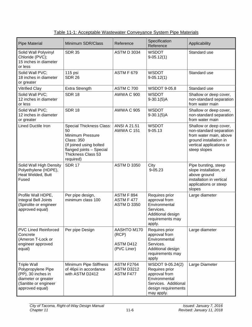
Table 11-1: Acceptable Wastewater Conveyance System Pipe Materials
Pipe Material Minimum SDR/Class Reference Specification Reference Applicability
Solid Wall Polyvinyl Chloride (PVC); 15 inches in diameter or less
SDR 35 ASTM D 3034 WSDOT 9-05.12(1)
Standard use
Solid Wall PVC; 18 inches in diameter or greater
115 psi SDR 26
ASTM F 679 WSDOT 9-05.12(1)
Standard use
Vitrified Clay Extra Strength ASTM C 700 WSDOT 9-05.8 Standard use Solid Wall PVC; 12 inches in diameter or less
SDR 18 AWWA C 900 WSDOT 9-30.1(5)A
Shallow or deep cover, non-standard separation from water main
Solid Wall PVC; 12 inches in diameter or greater
SDR 18 AWWA C 905 WSDOT 9-30.1(5)A
Shallow or deep cover, non-standard separation from water main
Lined Ductile Iron Special Thickness Class: 50 Minimum Pressure Class: 350 (If joined using bolted flanged joints – Special Thickness Class 53 required)
ANSI A 21.51 AWWA C 151
WSDOT 9-05.13
Shallow or deep cover, non-standard separation from water main, above ground installation in vertical applications or steep slopes
Solid Wall High Density Polyethylene (HDPE), Heat Welded, Butt Fused
SDR 17 ASTM D 3350 City 9-05.23
Pipe bursting, steep slope installation, or above ground installation in vertical applications or steep slopes
Profile Wall HDPE, Integral Bell Joints (Spirolite or engineer approved equal)
Per pipe design, minimum class 100
ASTM F 894 ASTM F 477 ASTM D 3350
Requires prior approval from Environmental Services. Additional design requirements may apply.
Large diameter
PVC Lined Reinforced Concrete (Ameron T-Lock or engineer approved equal)
Per pipe Design AASHTO M170 (RCP) ASTM D412 (PVC Liner)
Requires prior approval from Environmental Services. Additional design requirements may apply
Large diameter
Triple Wall Polypropylene Pipe (PP), 30 inches in diameter or greater (Sanitite or engineer approved equal)
Minimum Pipe Stiffness of 46pii in accordance with ASTM D2412
ASTM F2764 ASTM D3212 ASTM F477
WSDOT 9-05.24(2) Requires prior approval from Environmental Services. Additional design requirements may apply.
Large Diameter
City of Tacoma, Right-of-Way Design Manual Issued: January 7, 2016 Chapter 11 11-6 Revised: January 11, 2018
4.3.1 Stormwater Conveyance Pipe Materials The following table lists the acceptable pipe materials for stormwater conveyance systems. See the SWMM for allowable pipe materials for stormwater treatment and flow control facilities. The maximum out of round deflection allowed in flexible pipes is 5 percent. Galvanized, aluminized, and/or corrugated iron or steel pipes are not allowed within the public ROW or as a connection to the municipal system.
City of Tacoma, Right-of-Way Design Manual Issued: January 7, 2016 Chapter 11 11-7 Revised: January 11, 2018
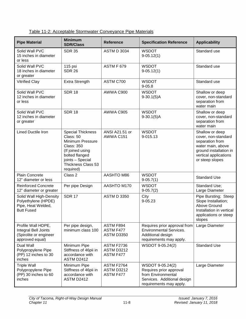
Table 11-2: Acceptable Stormwater Conveyance Pipe Materials
Pipe Material Minimum SDR/Class Reference Specification Reference Applicability
Solid Wall PVC 15 inches in diameter or less
SDR 35 ASTM D 3034 WSDOT 9-05.12(1)
Standard use
Solid Wall PVC 18 inches in diameter or greater
115 psi SDR 26
ASTM F 679 WSDOT 9-05.12(1)
Standard use
Vitrified Clay Extra Strength ASTM C700 WSDOT 9-05.8
Standard use
Solid Wall PVC 12 inches in diameter or less
SDR 18 AWWA C900 WSDOT 9-30.1(5)A
Shallow or deep cover, non-standard separation from water main
Solid Wall PVC 12 inches in diameter or greater
SDR 18 AWWA C905 WSDOT 9-30.1(5)A
Shallow or deep cover, non-standard separation from water main
Lined Ductile Iron Special Thickness Class: 50 Minimum Pressure Class: 350 (If joined using bolted flanged joints – Special Thickness Class 53 required)
ANSI A21.51 or AWWA C151
WSDOT 9-015.13
Shallow or deep cover, non-standard separation from water main, above ground installation in vertical applications or steep slopes
Plain Concrete 12” diameter or less
Class 2 AASHTO M86 WSDOT 9-05.7(1) Standard Use
Reinforced Concrete 12” diameter or greater
Per pipe Design AASHTO M170 WSDOT 9-05.7(2)
Standard Use; Large Diameter
Solid Wall High-Density Polyethylene (HPDE) Pipe, Heat Welded, Butt Fused
SDR 17 ASTM D 3350 City 9-05.23
Pipe Bursting; Steep Slope Installation; Above Ground Installation in vertical applications or steep slopes
Profile Wall HDPE, Integral Bell Joints (Spirolite or engineer approved equal)
Per pipe design, minimum class 100
ASTM F894 ASTM F477 ASTM D3350
Requires prior approval from Environmental Services. Additional design requirements may apply.
Large Diameter
Dual Wall Polypropylene Pipe (PP) 12 inches to 30 inches
Minimum Pipe Stiffness of 46pii in accordance with ASTM D2412
ASTM F2736 ASTM D3212 ASTM F477
WSDOT 9-05.24(2) Standard Use
Triple Wall Polypropylene Pipe (PP) 30 inches to 60 inches
Minimum Pipe Stiffness of 46pii in accordance with ASTM D2412
ASTM F2764 ASTM D3212 ASTM F477
WSDOT 9-05.24(2) Requires prior approval from Environmental Services. Additional design requirements may apply.
Large Diameter
City of Tacoma, Right-of-Way Design Manual Issued: January 7, 2016 Chapter 11 11-8 Revised: January 11, 2018
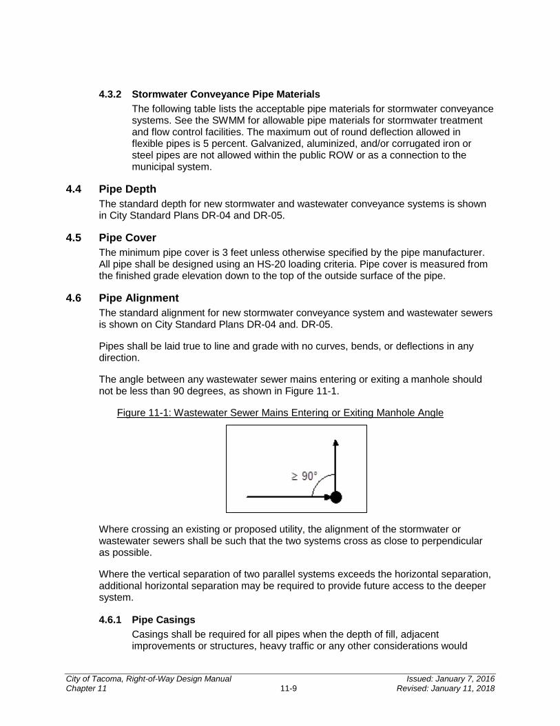
4.3.2 Stormwater Conveyance Pipe Materials The following table lists the acceptable pipe materials for stormwater conveyance systems. See the SWMM for allowable pipe materials for stormwater treatment and flow control facilities. The maximum out of round deflection allowed in flexible pipes is 5 percent. Galvanized, aluminized, and/or corrugated iron or steel pipes are not allowed within the public ROW or as a connection to the municipal system.
4.4 Pipe Depth The standard depth for new stormwater and wastewater conveyance systems is shown in City Standard Plans DR-04 and DR-05.
4.5 Pipe Cover The minimum pipe cover is 3 feet unless otherwise specified by the pipe manufacturer. All pipe shall be designed using an HS-20 loading criteria. Pipe cover is measured from the finished grade elevation down to the top of the outside surface of the pipe.
4.6 Pipe Alignment The standard alignment for new stormwater conveyance system and wastewater sewers is shown on City Standard Plans DR-04 and. DR-05.
Pipes shall be laid true to line and grade with no curves, bends, or deflections in any direction.
The angle between any wastewater sewer mains entering or exiting a manhole should not be less than 90 degrees, as shown in Figure 11-1.
Figure 11-1: Wastewater Sewer Mains Entering or Exiting Manhole Angle
Where crossing an existing or proposed utility, the alignment of the stormwater or wastewater sewers shall be such that the two systems cross as close to perpendicular as possible.
Where the vertical separation of two parallel systems exceeds the horizontal separation, additional horizontal separation may be required to provide future access to the deeper system.
4.6.1 Pipe Casings Casings shall be required for all pipes when the depth of fill, adjacent improvements or structures, heavy traffic or any other considerations would
City of Tacoma, Right-of-Way Design Manual Issued: January 7, 2016 Chapter 11 11-9 Revised: January 11, 2018
make conventional open trench replacement or repair work impractical. Some examples of improvements that would require a casing for stormwater or wastewater utilities are railroads, freeways, buildings, bridge abutments, retaining walls, structural slabs, and utility vaults. Requirements for casings include:
1. The casing material and joints shall be ductile iron or steel able to withstand the anticipated loadings.
2. The casing inside diameter shall be, at a minimum, 33 percent greater than the outside diameter of the carrier pipe or two standard pipe diameters larger than the carrier pipe, whichever is greater. However, the casing may need to be larger due to anticipated future upsizing of wastewater or stormwater sewer systems. Actual casing sizes will be specified by the Environmental Services Department.
3. The casing shall be leak proof. The ends of the casing pipe shall be sealed to prevent entry of water.
4. An analysis shall be performed to determine if cathodic protection or an increase in thickness is necessary to guarantee the pipes will maintain structural integrity for a minimum of 100 years.
5. All casing pipe welds shall be inspected by a third party testing agency, including both 100 percent visual weld inspection and using a non-destructive testing method recommended by the testing agency.
6. The casing shall extend to a point outside the loading zone of influence.
7. Pre-manufactured non-metallic or non-corrosive casing spacers shall be used to support the carrier pipe in the casing to facilitate pipe removal and installation and to prevent vertical movement of the carrier pipe. Spacing devices shall be sized to fit the casing pipe and installed in accordance with the manufacturer’s recommendations.
8. The annular space between carrier pipe and casing may be required to be filled as specified by the Environmental Services Department.
4.7 Pipe Couplings Rigid Couplings, manufactured by Romac Industries, Inc., or City approved equal, shall be used at any pipe joint in which bell and spigot or fused joints are not used and when connecting two dissimilar pipe materials. Flexible couplings are not permitted.
4.8 Pipe Bedding, Backfill and Backfill Compaction Pipe bedding and backfill shall conform to City Standard Plan SU-16. Backfill compaction shall conform to City Standard Plan SU-28.
4.9 Pipe Anchors The following table shows criteria to be used in determining whether pipe anchoring is required. Anchor design and spacing shall be submitted to the Environmental Services Department for approval. Table 11-3 applies to pipe anchoring above and below ground. Only Solid Wall HDPE and Lined Ductile Iron pipe should be used in above ground installations.
City of Tacoma, Right-of-Way Design Manual Issued: January 7, 2016 Chapter 11 11-10 Revised: January 11, 2018

Table 11-3: Pipe Anchor Requirements
Pipe Material Pipe Slope
Requiring Pipe Anchors
Maximum Slope Allowed
Maximum Velocity at Full Flow
PVC1 ≥20% 30%3 30 fps Vitrified Clay1 ≥10% 20%3 30 fps Lined Ductile Iron4 ≥40% None None Solid Wall HDPE2 ≥50% None None Concrete 10% 20%3 30 fps
1 Not allowed in landslide hazard areas. 2 Butt fused pipe joints required. Above-ground installation is required on slopes greater than 40 percent
to minimize disturbance to steep slopes. 3 Maximum slope of 200 percent allowed for these pipes with no joints (one section) with structures at
each end and properly grouted. 4 Restrained joints required on slopes greater than 25 percent. Above-ground installation is required on
slopes greater than 40 percent to minimize disturbance to steep slopes.
4.10 Considerations for Future Development The potential for future development shall be considered in the design of the stormwater and wastewater sewer systems. The Environmental Services Department may require a change in the size and depth of the systems.
4.11 Pipe Buoyancy Pipe buoyancy should be considered when there is a possibility that pipe flotation could occur including:
• Pipe placed in areas with high groundwater table.
• Pipe placed in areas subject to flooding such as floodplains
• Pipe placed underwater.
Whenever the potential for flotation exists, the design engineer should design the system accordingly which may include consideration for heavier pipe or appropriate pipe anchors. When designing the system, the pipe should be considered empty in the event the line must be dewatered. Pipe buoyancy design shall be submitted to the Environmental Services Department for review and approval.
SECTION 5 Manhole Design Criteria
5.1 Manhole Locations The maximum distance between manholes is 400 linear feet for the wastewater sewer system and 350 linear feet for stormwater conveyance system. For the stormwater system if the minimum slope requirement of 0.5 percent cannot be met, the maximum distance between manholes shall be 200 linear feet.
In addition, manholes are required in the following locations:
• The intersection of any sewers;
• The dead end of a conveyance system;
• Any alignment or grade changes;
City of Tacoma, Right-of-Way Design Manual Issued: January 7, 2016 Chapter 11 11-11 Revised: January 11, 2018
• Catch basin lead connections;
• Any connection of private side sewers that are 8-inches in diameter or greater; or
• As otherwise required by the Environmental Services Department.
5.2 Manhole Types All manholes shall either be Type 1 or 2 concrete manholes with concentric cones for up to 54 inch diameter manholes and eccentric cones for 60 inch or greater manholes as shown on the City Standard Plans SU-17 and SU-18. The use of Type 3 concrete manholes requires prior approval from the Environmental Services Department. The use of non-concrete manholes requires prior approval from the Environmental Services Department.
Manhole size shall be determined by pipe diameter and orientation at the manhole. The design engineer should verify that the manhole diameter is large enough to accommodate all incoming and outgoing pipes without jeopardizing the integrity of the manhole. City Standard Plans SU-17, SU-18, and SU-19 provide the minimum distance allowed between pipe openings.
A plan view of the manhole, drawn to scale, will be required when more than four pipes enter the structure on the same plane, or if angles of approach and clearance between pipes is of concern. The plan view (and section if necessary) must demonstrate the minimum distance requirements between knockouts per the City of Tacoma Standard Plans (SU-17, SU-18, or SU-19) can be maintained.
The bases of all manholes shall be channelized in accordance with City Standard Plans SU-17, SU-18, and SU-19. City manholes generally do not have sumps though some manholes, such as flow control manholes associated with the stormwater system, may contain sumps.
5.3 Manhole Covers All manhole frames and covers shall be as shown on City Standard Plan SU-22.
All manholes located in sidewalk sections shall have a solid locking cover. The sidewalk section shall be a minimum of 6 inches thick in the vicinity of the manhole.
Other manholes needing solid locking covers may be identified through the City review/design process on a case-by-case basis. Examples where locking manhole lids might be required include: floodplains, sidewalks, gulches, undeveloped ROWs, and other low drainage areas (to prevent inflow of stormwater).
5.4 Connections to Manholes Where connecting two or more mains of equal size to a manhole, the invert elevations of the upstream pipes shall be 0.1 foot higher than the invert elevation of the downstream pipe.
Pipes of different diameters shall be aligned vertically in manholes by one of the following methods, listed in order of preference: match pipe crowns per Figure 11-2, match 80 percent depth point measured from the invert elevation, match pipe inverts, or for stormwater systems only, use City approved drop inlet connection. Where inlet pipes are significantly higher than outlet pipes, special design features may be required.
City of Tacoma, Right-of-Way Design Manual Issued: January 7, 2016 Chapter 11 11-12 Revised: January 11, 2018
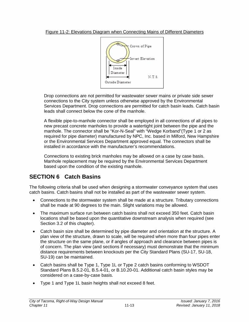
Figure 11-2: Elevations Diagram when Connecting Mains of Different Diameters
Drop connections are not permitted for wastewater sewer mains or private side sewer connections to the City system unless otherwise approved by the Environmental Services Department. Drop connections are permitted for catch basin leads. Catch basin leads shall connect below the cone of the manhole.
A flexible pipe-to-manhole connector shall be employed in all connections of all pipes to new precast concrete manholes to provide a watertight joint between the pipe and the manhole. The connector shall be “Kor-N-Seal” with “Wedge Korband”(Type 1 or 2 as required for pipe diameter) manufactured by NPC, Inc. based in Milford, New Hampshire or the Environmental Services Department approved equal. The connectors shall be installed in accordance with the manufacturer’s recommendations.
Connections to existing brick manholes may be allowed on a case by case basis. Manhole replacement may be required by the Environmental Services Department based upon the condition of the existing manhole.
SECTION 6 Catch Basins
The following criteria shall be used when designing a stormwater conveyance system that uses catch basins. Catch basins shall not be installed as part of the wastewater sewer system.
• Connections to the stormwater system shall be made at a structure. Tributary connections shall be made at 90 degrees to the main. Slight variations may be allowed.
• The maximum surface run between catch basins shall not exceed 350 feet. Catch basin locations shall be based upon the quantitative downstream analysis when required (see Section 3.2 of this chapter).
• Catch basin size shall be determined by pipe diameter and orientation at the structure. A plan view of the structure, drawn to scale, will be required when more than four pipes enter the structure on the same plane, or if angles of approach and clearance between pipes is of concern. The plan view (and sections if necessary) must demonstrate that the minimum distance requirements between knockouts per the City Standard Plans (SU-17, SU-18, SU-19) can be maintained.
• Catch basins shall be Type 1, Type 1L or Type 2 catch basins conforming to WSDOT Standard Plans B.5.2-01, B.5.4-01, or B.10.20-01. Additional catch basin styles may be considered on a case-by-case basis.
• Type 1 and Type 1L basin heights shall not exceed 8 feet.
City of Tacoma, Right-of-Way Design Manual Issued: January 7, 2016 Chapter 11 11-13 Revised: January 11, 2018
• Type 2 (48 inches minimum diameter) catch basins shall be used at the following locations or for the following situations:
When overall structure height exceeds 8 feet; or When all pipes tying into the structure exceed the limits set for Type 1 structures.
• All Type 2 catch basins shall be preapproved by Environmental Services.
• In sag conditions, a combination inlet per WSDOT Standard Plan B-25.20-01 is required.
• Catch basin grates shall be vaned grates per WSDOT Standard Plan B-30.30-01 or WSDOT Standard Plan B-30.40-01.
• Where existing catch basins are modified, grates may be required to be replaced with vaned grates. Environmental Services will make the final determination based on the condition of the existing grate.
• To accommodate maintenance, quarry spalls shall not be placed around catch basin inlets.
• The maximum slope of ground surface for a radius of 5 feet around a catch basin grate shall be 3:1. The preferred slope is 5:1 to facilitate maintenance access.
• Catch basins shall be designed for H-20 loading.
• Catch basin leads shall be no longer than 50 feet unless preapproved by Environmental Services.
• Catch basins shall be located:
Such that the inlet is placed next to the face of the curb and at an elevation to collect stormwater runoff (the structure offset shown on the plans shall be to center of grate, not center of structure to ensure grate location is appropriate);
At the low point of any sag vertical curve or grade break where the grade of roadway transitions from a negative to a positive grade;
Prior to any intersection such that a minimal amount of water flows across the intersection, through a curb ramp, or around a street return;
Prior to transitions from a typical crown to a full warp through a downhill grade; and Upstream of curb ramps outside of the wing of the curb ramp.
• Catch basins shall not be located in:
Areas of expected pedestrian traffic; Crosswalks; The wheel path of vehicles; Driveways; Graveled areas or high sediment generating areas unless pretreatment is provided
(reference SWMM, Volume 5); and Areas where they will conflict with other utilities.
• Where the City of Tacoma Curb Ramp Installation Matrix or other departmental review or requirements require a new curb ramp, a replacement of a curb ramp, or an upgrade to a curb ramp, drainage shall be provided to ensure water does not flow across the curb ramp. This may require the installation of new catch basins, the removal and replacement
City of Tacoma, Right-of-Way Design Manual Issued: January 7, 2016 Chapter 11 11-14 Revised: January 11, 2018
of existing catch basins or other revisions to the stormwater system as necessary to ensure appropriate stormwater mitigation.
• All catch basins, inlets, etc. shall be marked. Environmental Services stocks some curb markers for both public and private project. Contact Environmental Services at (253) 591-5588 to obtain curb markers for the project.
• Changes in pipe direction, or increases or decreases in pipe size shall only be allowed at structures.
• For Type 1 and 1L, catch basin to catch basin connections shall not be allowed. Catch basins within stormwater facilities (such as bioretention facilities) may be allowed to connect to catch basins that are part of the stormwater conveyance system.
• Bubble up systems shall not be allowed.
• Connections to catch basins shall be made using sand collars.
SECTION 7 Low Pressure Grinder Pump Wastewater Systems
The use of a low pressure grinder pump wastewater system may be an alternative to conventional gravity wastewater system only if the site cannot be serviced by a conventional gravity system due to topography. Grinder pump systems consist of using individual grinder pumps for each parcel served which are connected to a shared pressure pipe then discharged to a gravity wastewater system. These systems require prior approval from Environmental Services.
Grinder pump systems shall be designed in accordance with the Washington State Department of Ecology Criteria for Sewage Works Design. Additional design criteria may apply based on site specific conditions and layouts of the site to be served.
All shared pressure pipes shall be publicly owned. Pressure pipes and grinder pumps servicing each individual parcel shall be privately owned to the point of connection to the shared pressure pipe. Property owners are responsible for repair, replacement, and maintenance of the service line, tanks, pumps, alarms, etc.
Environmental Services may limit the number of grinder pumps discharging into the public gravity system or may require the installation of corrosion protection on downstream pipes or manholes. The length of the system requiring corrosion protection will depend on the specific site, materials of the existing downstream system, and the number of grinder pumps installed.
Low pressure systems shall follow all applicable requirements for locations, easements, separation from other utilities, etc. as identified in this Manual.
The type and model of pumps shall be the same for all parcels served in the system unless otherwise approved by Environmental Services.
Privately owned pumps and tanks shall be located outside the dedicated public ROW areas. A covenant and easement agreement is required for the proposed pump system to ensure proper maintenance and inform future property owners of the requirements of being served by this type of system. The covenant and easement agreement also provides information regarding which type and size of pump is acceptable for replacement to ensure the system remains in good working condition for all future property owners. The document shall be recorded to title. The
City of Tacoma, Right-of-Way Design Manual Issued: January 7, 2016 Chapter 11 11-15 Revised: January 11, 2018
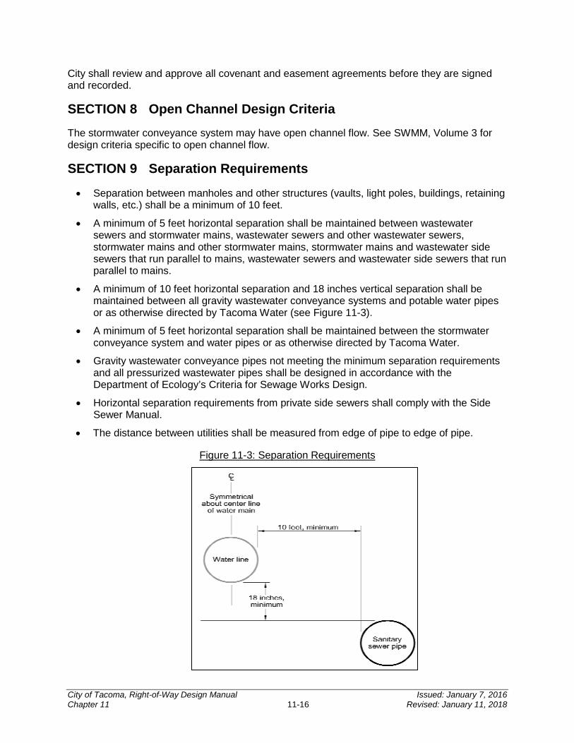
City shall review and approve all covenant and easement agreements before they are signed and recorded.
SECTION 8 Open Channel Design Criteria
The stormwater conveyance system may have open channel flow. See SWMM, Volume 3 for design criteria specific to open channel flow.
SECTION 9 Separation Requirements
• Separation between manholes and other structures (vaults, light poles, buildings, retaining walls, etc.) shall be a minimum of 10 feet.
• A minimum of 5 feet horizontal separation shall be maintained between wastewater sewers and stormwater mains, wastewater sewers and other wastewater sewers, stormwater mains and other stormwater mains, stormwater mains and wastewater side sewers that run parallel to mains, wastewater sewers and wastewater side sewers that run parallel to mains.
• A minimum of 10 feet horizontal separation and 18 inches vertical separation shall be maintained between all gravity wastewater conveyance systems and potable water pipes or as otherwise directed by Tacoma Water (see Figure 11-3).
• A minimum of 5 feet horizontal separation shall be maintained between the stormwater conveyance system and water pipes or as otherwise directed by Tacoma Water.
• Gravity wastewater conveyance pipes not meeting the minimum separation requirements and all pressurized wastewater pipes shall be designed in accordance with the Department of Ecology’s Criteria for Sewage Works Design.
• Horizontal separation requirements from private side sewers shall comply with the Side Sewer Manual.
• The distance between utilities shall be measured from edge of pipe to edge of pipe.
Figure 11-3: Separation Requirements
City of Tacoma, Right-of-Way Design Manual Issued: January 7, 2016 Chapter 11 11-16 Revised: January 11, 2018
SECTION 10 Access and Easements
See CHAPTER 13 for additional information concerning ROW and easements.
Maintenance access shall be provided for all City-owned facilities and conveyance systems. A minimum 15 foot wide access easement which is separate and distinct from the public utility easement shall be provided to manholes or other components of the system not accessible via a public utility easement. The public utility easement is the easement in which the utility and all appurtenances are contained though access to the structures may be necessary from another location, such as top of slope. The access easement shall have a minimum 12 foot wide crushed rock or HMA surface. The access may consist of HMA with a maximum grade of 15 percent or crushed surfacing base course (CSBC) with a maximum grade of 12 percent. HMA shall be a minimum thickness of 2 inches and in accordance with City Special Provision 5-04 and WSDOT Specification 5-04. CSBC shall be a minimum thickness of 3 inches and in accordance with WSDOT Specification 9-03.9(3). If access is required over sidewalks, sidewalks shall be designed for HS-20 loading.
Public easements are easements granted by private entities to the City for access, maintenance, and protection of City infrastructure.
For easements dedicated to the City for the purpose of stormwater systems or wastewater sewers, the following typically applies. The actual easement document will contain all applicable restrictions or allowances.
No permanent structures(s) shall be erected within the easement area(s) unless specifically approved in writing by the Director of Environmental Services. Permanent structures shall mean any concrete foundation, concrete slab, wall, rockery, building, deck, and overhanging structures, fill material, recreational sport courts, carports, portable sheds, private utilities, fences, or other site improvement that will unreasonably interfere with the need to access or construct utilities in said easements(s). Permanent structures shall not mean improvements such as normal landscaping, asphalt paving, gravel, or other similar site improvements that do not prevent the access of people, materials, and machinery across, along, and within the said easement area. Land restoration by the City within the said easement area will be strictly limited to grass seed, grass sod, and/or asphalt replacement unless otherwise determined by the City.
Preliminary project planning should take into account the potential loss of buildable area or the need to purchase more property as a result of stormwater facilities and wastewater sewers and their associated necessary easements and tracts.
All publicly maintained wastewater sewers and stormwater conveyance systems shall be located in dedicated tracts, public easements, or public ROWs. All pipes and channels shall be centered within the easement. Easement widths may be increased for pipes greater than 3 feet in diameter and open channels with top widths greater than 5 feet. The depth or proximity of steep slopes to the public system may necessitate a larger easement requirement for future excavation and maintenance purposes. See Table 11-4 and Table 11-5 below for appropriate easement widths based upon depth of pipe.
Public wastewater sewer easements shall conform to Table 11-4. Public stormwater easements shall be a minimum of 20 feet in width and conform to Table 11-5.
City of Tacoma, Right-of-Way Design Manual Issued: January 7, 2016 Chapter 11 11-17 Revised: January 11, 2018
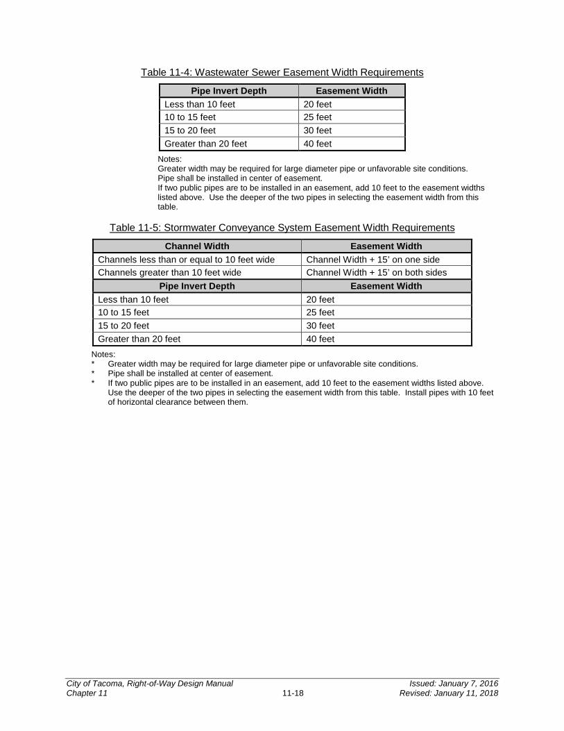
Table 11-4: Wastewater Sewer Easement Width Requirements
Pipe Invert Depth Easement Width Less than 10 feet 20 feet 10 to 15 feet 25 feet 15 to 20 feet 30 feet Greater than 20 feet 40 feet
Notes: Greater width may be required for large diameter pipe or unfavorable site conditions. Pipe shall be installed in center of easement. If two public pipes are to be installed in an easement, add 10 feet to the easement widths listed above. Use the deeper of the two pipes in selecting the easement width from this table.
Table 11-5: Stormwater Conveyance System Easement Width Requirements
Channel Width Easement Width Channels less than or equal to 10 feet wide Channel Width + 15’ on one side Channels greater than 10 feet wide Channel Width + 15’ on both sides
Pipe Invert Depth Easement Width Less than 10 feet 20 feet 10 to 15 feet 25 feet 15 to 20 feet 30 feet Greater than 20 feet 40 feet
Notes: * Greater width may be required for large diameter pipe or unfavorable site conditions. * Pipe shall be installed at center of easement. * If two public pipes are to be installed in an easement, add 10 feet to the easement widths listed above.
Use the deeper of the two pipes in selecting the easement width from this table. Install pipes with 10 feet of horizontal clearance between them.
City of Tacoma, Right-of-Way Design Manual Issued: January 7, 2016 Chapter 11 11-18 Revised: January 11, 2018
CHAPTER 12Water Plans
INTRODUCTION ................................................................................... 12-2
SECTION 1 Initiation of the Process for Design and Approval of Water Plans ...................................................................................... 12-2
SECTION 2 Pre-Construction ......................................................... 12-2
SECTION 3 Construction ................................................................ 12-3
SECTION 4 Post Construction ....................................................... 12-3
SECTION 5 Reference Coordinates ............................................... 12-3
12
City of Tacoma, Right-of-Way Design Manual Issued: January 7, 2016 Chapter 12 12-1 Revised: January 11, 2018
INTRODUCTION
It should be noted that submittal and approval of the water plans is a separate and distinct process from the ROW Construction/Work Order Permit process. Please note that it is the responsibility of the design engineer to coordinate the ROW Construction/Work Order Permit plans and the water plans and verify that no conflicts occur.
When proposed water mains will be located within the ROW, water mains are to be laid to the permanent grade and alignment of the street or alley (TMC 10.24.050). Tacoma Water will submit plans to the City Engineer to certify the permanent grade and alignment of the street or alley (TMC 10.24.060). In the case when the permanent grade and alignment of the street or alley has not been established, Tacoma Water will request that the Public Works Department establish the permanent grade and alignment of said street or alley. The cost of establishing the permanent grade and alignment of the street or alley shall be borne by the project proponent.
SECTION 1 Initiation of the Process for Design and Approval of Water Plans
Extension of water mains and the installation of fire hydrants may be required where specified by the development conditions; by Tacoma Public Utilities, Water Division (Tacoma Water); or by the IFC with state adopted amendments. The applicant should contact Tacoma Water’s Permit Counter at (253) 502-8247 and submit a copy of the site plan to initiate the water plan design and approval process.
Based on the submitted site plan, a preliminary design and pre-design letter will be prepared by Tacoma Water. The pre-design letter will indicate the engineering fees and other requirements the applicant is responsible for, associated with the water main extension.
Water mains can also be installed by Local Improvement Districts (see CHAPTER 2). Contact should be made with Tacoma Water at (253) 502-8247 regarding the process by which a water main is designed and constructed under an Local Improvement District.
Prior to the initiation of the design, the applicant shall remit to the Tacoma Water’s Permit Counter:
• The design/inspection fee, and signed time and material agreement as stated in the pre-design letter. Please note that the fee and agreement alone are not acceptable without sufficient construction plans as noted below.
• A set of construction plans that have been submitted to the building permit agency for initial review. If in using these plans, errors are found or changes are required, which necessitate a redesign of the water main, the project may be shifted to a later point in the water design queue. The water design will be resumed when the plans are deemed adequate for water design and scheduling of permits. An electronic copy of the plans should also be submitted to aid and expedite the design of the water plans.
SECTION 2 Pre-Construction
Upon approval of the water plans by Tacoma Water and, if necessary, the Public Works Department, Tacoma Water will notify the applicant that the plans and specifications are ready to be picked up.
City of Tacoma, Right-of-Way Design Manual Issued: January 7, 2016 Chapter 12 12-2 Revised: January 11, 2018
The applicant shall provide a legal description of the water main easement to Tacoma Water for review and processing. This must be completed and stamped by a professional land surveyor licensed in Washington State. The easement must be approved and recorded prior to any construction beginning.
The applicant will select a contractor and supply the contractor’s information to Tacoma Water. Tacoma Water will prepare the contract documents and notify the developer when they are ready to be picked up. The developer and contractor will obtain, sign and process the contract documents and return them to Tacoma Water at which time they must be reviewed and approved by the City Attorney’s Office and signed by all reviewing parties.
Concurrently, Tacoma Water will supply to the developer an estimate for cost of inspection, flushing and sampling, and a Time and Material Agreement to cover these items. Upon receipt of the estimated fees, the Time and Material Agreement, and upon approval of the contract documents by the City Attorney’s Office, a pre-construction meeting with the contractor will be held.
Please note that construction shall not begin until completion of the pre-construction meeting between the contractor and Tacoma Water.
For proper scheduling, the fees for the installation of water services should be paid prior to the time of the pre-construction meeting.
SECTION 3 Construction
It is the responsibility of the applicant to provide a professional land surveyor registered in the State of Washington to stake the water main for construction in accordance with the approved plans and specifications.
Tacoma Water will provide labor and materials to inspect, flush and sample the water main, including installation and removal of sample stations. It should be noted that if the water main design must be altered after start of construction because of incorrect data furnished by the developer, the construction will stop and will not resume until a redesign fee has been paid to Tacoma Water and plans have been revised and approved.
SECTION 4 Post Construction
Tacoma Water will issue a preliminary acceptance letter after the water main is placed in service.
SECTION 5 Reference Coordinates
Please note that the design engineer must reference the project to the Washington State Plane Coordinate System. Contact the Public Works Department at (253) 591-5525 for survey coordinate information.
City of Tacoma, Right-of-Way Design Manual Issued: January 7, 2016 Chapter 12 12-3 Revised: January 11, 2018

CHAPTER 13Construction Related Permits and Easements
INTRODUCTION ................................................................................... 13-2
SECTION 1 Temporary Construction Easement ........................... 13-2
SECTION 2 ROW Dedication .......................................................... 13-2
SECTION 3 Easements ................................................................... 13-2 3.1 Private Accessway Easements ............................................................................... 13-3 3.2 Recording Prior to Work Order Approval................................................................. 13-3 3.3 Easement Recording Procedure ............................................................................. 13-3
SECTION 4 Traffic Control Requirements ..................................... 13-3 4.1 Street Closures, Non-Arterial Streets ...................................................................... 13-4 4.2 Lane and Street Closures, Arterial Streets .............................................................. 13-4 4.3 Notification .............................................................................................................. 13-4
SECTION 5 Environmental Checklist and EIS ............................... 13-4
SECTION 6 Erosion Control and Contaminated Soils .................. 13-5 6.1 Erosion Control ....................................................................................................... 13-5 6.2 Contaminated Soils ................................................................................................ 13-5
13
City of Tacoma, Right-of-Way Design Manual Issued: January 7, 2016 Chapter 13 13-1 Revised: January 11, 2018
INTRODUCTION
This chapter focuses on miscellaneous subjects that may have applicability to any proposed development within the City ROW including easements, dedications, State Environmental Policy Act (SEPA), and erosion and sediment control.
SECTION 1 Temporary Construction Easement
The Temporary Construction Easement shall be completed for each adjacent private property impacted by the project prior to ROW Construction/Work Order Permit approval and construction. Adverse impacts to properties include, but are not be limited to, discontinuity in grade, abrupt meet lines, access to driveways and garages, and drainage problems created or intensified as a result of the project. Measures taken to resolve adverse impacts shall be shown on the project construction drawings. Unless otherwise agreed upon, slopes shall be constructed using cuts and fills no steeper than 2:1. Where sidewalks are not being constructed, a graded pedestrian walk area shall be provided at a 2 percent slope immediately adjacent to the roadway. It is the design engineer's responsibility to identify and resolve adverse impacts to affected properties prior to release of construction plans.
A copy of the easement for construction on private property is provided at the end of this chapter (Attachment 13-1). Private entities should contact the Site Development Group to obtain the most recent version of this document. City staff should coordinate easement language with Real Property Services.
SECTION 2 ROW Dedication In some instances additional ROW dedication from adjacent property owners may be required to accommodate the proposed improvements. It is then incumbent upon the applicant to acquire said ROW. In instances where additional ROW is required, said ROW must be dedicated to the City prior to ROW Construction/Work Order Permit plan approval, except in the case of pending plat approvals.
In instances where the ROW will be dedicated to the City as part of the plat and/or required in the conditions, said ROW may be dedicated at the time of final plat.
SECTION 3 Easements Easements are generally divided into two distinct categories: public easements and private easements. A public easement is granted by a party to the City, such as an access easement to allow entry onto private property to access a publicly owned utility facility, or a utility easement for a utility to cross private property. An easement to allow City staff to enter a property and inspect a private facility or a site may also be granted.
A private easement is granted between two or more private parties, such as an access easement for a driveway across an adjacent parcel or a utility easement to allow a private utility to cross another private parcel. The City may also require covenant and easement agreements to ensure private facilities are appropriately inspected and maintained. These are agreements between the City and the private entity. All public easements granted to the City or to allow work permitted by the City, and all covenant and easement agreements shall be legally recorded with the Pierce County Auditor.
City of Tacoma, Right-of-Way Design Manual Issued: January 7, 2016 Chapter 13 13-2 Revised: January 11, 2018

Note: Preliminary project planning should account for the potential loss of buildable area or the need to purchase more property as a result of easement needs.
Refer to CHAPTER 11 for specific easement requirements for public stormwater and wastewater systems.
3.1 Private Accessway Easements Private accessway easement widths are as specified in CHAPTER 4 and shall also comply with applicable design manuals and guidance as specified in TMC 13.04.160. Please note that this is a separate and distinct easement from any public easement required for the site. Public easements may be granted and contained within private accessway easements.
3.2 Recording Prior to Work Order Approval Easements shall be provided to the City prior to ROW Construction/Work Order Permit approval except for plats or short plats where easements may be provided at the time of final plat or short plat approval.
3.3 Easement Recording Procedure The following procedure shall be used for recording public easements:
• Determine the required easement size, footprint or width and location as outlined in this Manual or as mandated through the plan review process.
• Provide a legal description for the easement and submit it along with an acceptable plan showing the location of said easement to Real Property Services. Real Property Services is located on the third floor of the Tacoma Municipal Building at 747 Market Street; call (253) 591-5535 for additional information.
• Real Property Services will review the legal description for accuracy and draft the easement document.
• The draft easement document will be reviewed internally by City staff and signed by the appropriate City staff.
• The signed easement document is sent to the applicant for the required signatures of the property owners. These signatures must be notarized.
• It is then the responsibility of the applicant to return the signed easement form to the Real Property Services, who will record the document with the Pierce County Auditor’s office.
SECTION 4 Traffic Control Requirements
All work within the public ROW that may affect traffic (both vehicular and pedestrian) shall provide traffic control. The Traffic Control Handbook available on the govME website provides requirements and guidance for creating traffic control plans.
All ROW Construction/Work Order Permits with new improvements within an existing roadway, or any construction that will adversely impact the flow of traffic shall include the minimum special traffic control requirements on the plan set.
City of Tacoma, Right-of-Way Design Manual Issued: January 7, 2016 Chapter 13 13-3 Revised: January 11, 2018
Exceptions to the typical requirements will be required for any construction contained within an arterial street. Exceptions in these cases will be written by Traffic Engineering and will be required to be shown on the plan sets.
A copy of the typical special traffic control requirements, with the format of typical exceptions, can be found at the end of this chapter.
4.1 Street Closures, Non-Arterial Streets All street closures will be approved on a project-by-project basis. Generally, non-arterial streets may be closed to through traffic, provided that local access is maintained at all times with a minimum of a 20 foot wide access lane. It is required that closures be coordinated with the businesses and/or residences adjacent to the project site. A minimum of one access shall be maintained to all properties at all times.
4.2 Lane and Street Closures, Arterial Streets Generally, it is necessary that traffic be maintained at all times on arterial streets. When necessary, and justified, lanes of traffic may be closed during specified hours of the day. The determination of these hours shall be in consultation with the City Traffic Engineering section and subject to the approval of the City Traffic Engineer. Only in unusual circumstances will full closures of arterial streets be considered.
Local access must be maintained at all times with a minimum of a 20 foot wide access lane. Again, it is required that closures be coordinated with the various businesses and/or residences adjacent to the project site. A minimum of one access shall be maintained to all properties at all times.
4.3 Notification The contractor shall notify the following group three working days prior to any street closure:
Engineering Division (253) 591-5500 Streets and Grounds (253) 591-5495 Solid Waste (253) 591-5544 Tacoma Fire Department (253) 591-5733 Tacoma Police Department (253) 591-5951 LESA Communication Center (253) 798-4721 – Option 3 Tacoma Public Schools Transportation Office (253) 571-1853 Pierce Transit (253) 581-8109
SECTION 5 Environmental Checklist and EIS
The SEPA, Chapter 43.21C RCW, requires all governmental agencies to consider the environmental impacts of a proposal before making decisions. An environmental checklist is required to be filed with the City for all projects that do not meet specific exemption thresholds. The purpose of the environmental checklist is to provide information to help the applicant and City to identify impacts from the proposal (and to reduce or avoid impacts from the proposal, where applicable) and to help the City determine whether an environmental impact statement (EIS) is required. An EIS is required for all proposals that have probable significant adverse impacts on the quality of the environment. See City Tip Sheet P-110.
City of Tacoma, Right-of-Way Design Manual Issued: January 7, 2016 Chapter 13 13-4 Revised: January 11, 2018
In many cases, an environmental checklist may be required in conjunction with the improvements outlined on the ROW Construction/Work Order Permit plan sets unless the project completely falls under an exemption. The complete set of categorical exemptions is contained in the SEPA rules (Chapter 197-11 WAC) and the City of Tacoma’s Environmental Code (TMC 13.12). The thresholds outlined in WAC 197-11 and TMC 13.12 that are most frequently encountered in the work order process requiring an environmental checklist include:
• Any utility pipe installed greater than 12 inches in diameter.
• Any fill or excavation in excess of 500 cubic yards.
Information on, and the filing of, the environmental checklist shall be through Planning and Development Services at www.tacomapermits.org and (253) 591-5030. If an environmental checklist is required for the improvements to be constructed under the ROW Construction/Work Order Permit, the environmental review process must be completed and a final environmental determination obtained prior to permit approval. If the project is associated with a land use action, SEPA is typically completed as part of the land use permitting process.
SECTION 6 Erosion Control and Contaminated Soils
6.1 Erosion Control All projects are responsible for preventing erosion and discharge of sediment and other pollutants into receiving waters. The following projects shall complete a SWPPP per the SWMM, Volume 2:
• Projects resulting in 2,000 square feet, or greater, of new, replaced, or new plus replaced hard surface, or
• Those which have land-disturbing activity of 7,000 square feet or greater.
6.2 Contaminated Soils Contaminated soils may be located in the city. If contaminated soils are discovered they should be properly disposed of.
The City has developed an internal Soil Management Plan regarding contaminated soil testing and disposal for City capital delivery projects and maintenance projects completed by City staff. The Soil Management Plan addresses soil sample collection and analysis, and disposal for soil contaminated with arsenic and lead in the Tacoma Smelter Plume area.
For projects completed by private developers, the City may require specific soil sampling on a case by case basis.
City of Tacoma, Right-of-Way Design Manual Issued: January 7, 2016 Chapter 13 13-5 Revised: January 11, 2018
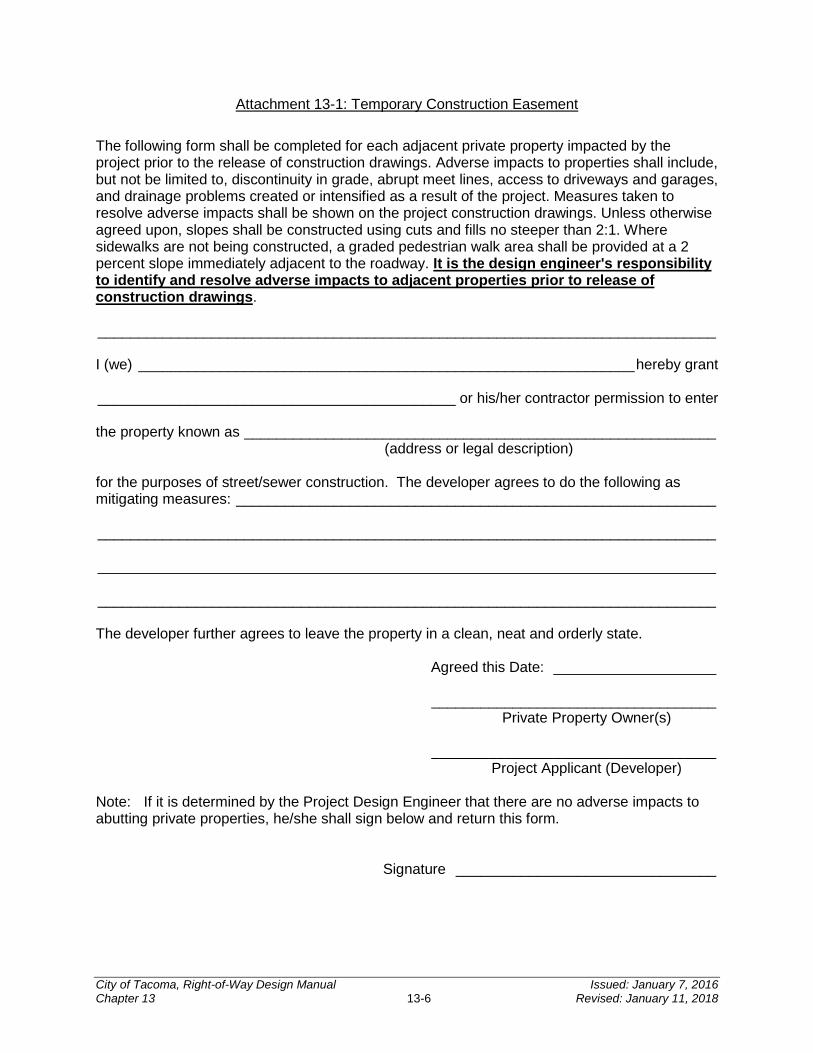
Attachment 13-1: Temporary Construction Easement
The following form shall be completed for each adjacent private property impacted by the project prior to the release of construction drawings. Adverse impacts to properties shall include, but not be limited to, discontinuity in grade, abrupt meet lines, access to driveways and garages, and drainage problems created or intensified as a result of the project. Measures taken to resolve adverse impacts shall be shown on the project construction drawings. Unless otherwise agreed upon, slopes shall be constructed using cuts and fills no steeper than 2:1. Where sidewalks are not being constructed, a graded pedestrian walk area shall be provided at a 2 percent slope immediately adjacent to the roadway. It is the design engineer's responsibility to identify and resolve adverse impacts to adjacent properties prior to release of construction drawings. ____________________________________________________________________________ I (we) _____________________________________________________________ hereby grant ____________________________________________ or his/her contractor permission to enter the property known as __________________________________________________________ (address or legal description) for the purposes of street/sewer construction. The developer agrees to do the following as mitigating measures: ___________________________________________________________ ____________________________________________________________________________ ____________________________________________________________________________ ____________________________________________________________________________ The developer further agrees to leave the property in a clean, neat and orderly state. Agreed this Date: ____________________ ___________________________________ Private Property Owner(s) ___________________________________ Project Applicant (Developer) Note: If it is determined by the Project Design Engineer that there are no adverse impacts to abutting private properties, he/she shall sign below and return this form. Signature ________________________________
City of Tacoma, Right-of-Way Design Manual Issued: January 7, 2016 Chapter 13 13-6 Revised: January 11, 2018
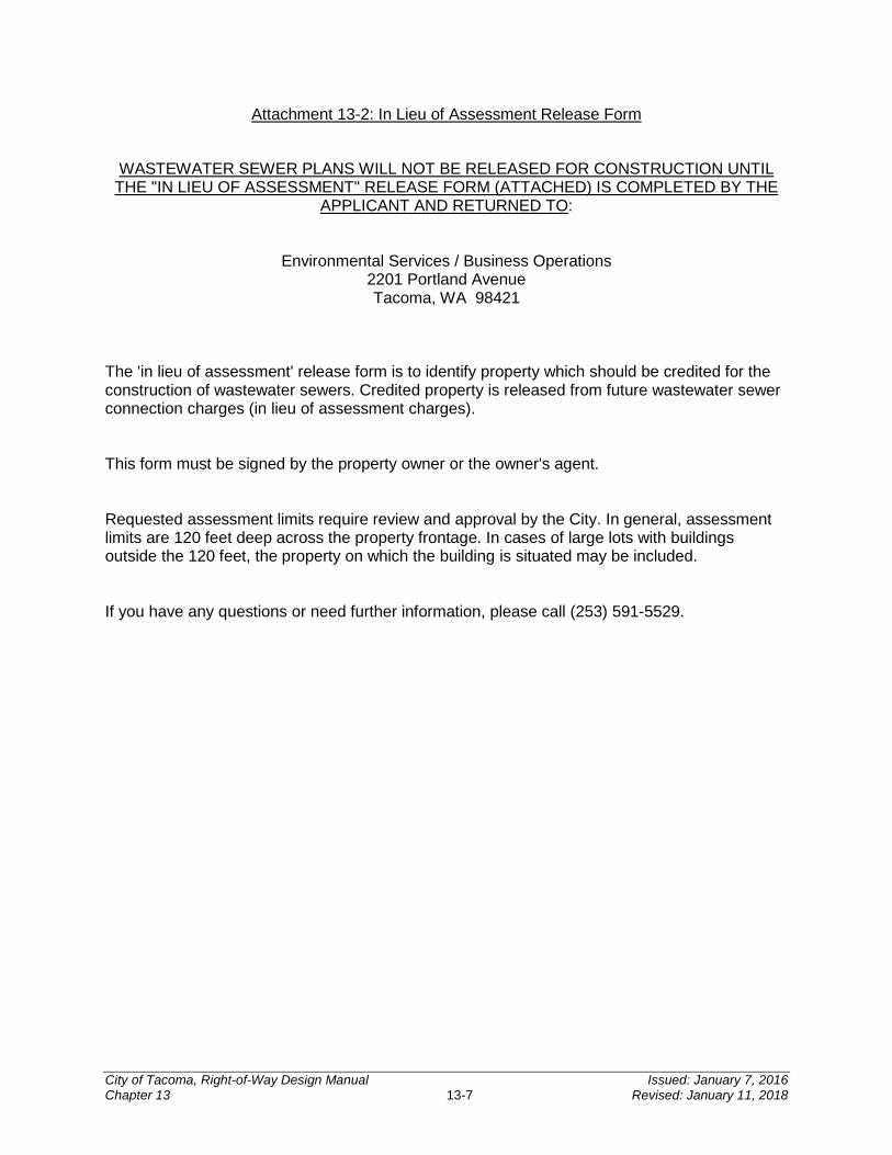
Attachment 13-2: In Lieu of Assessment Release Form
WASTEWATER SEWER PLANS WILL NOT BE RELEASED FOR CONSTRUCTION UNTIL THE "IN LIEU OF ASSESSMENT" RELEASE FORM (ATTACHED) IS COMPLETED BY THE
APPLICANT AND RETURNED TO:
Environmental Services / Business Operations 2201 Portland Avenue Tacoma, WA 98421
The 'in lieu of assessment' release form is to identify property which should be credited for the construction of wastewater sewers. Credited property is released from future wastewater sewer connection charges (in lieu of assessment charges). This form must be signed by the property owner or the owner's agent. Requested assessment limits require review and approval by the City. In general, assessment limits are 120 feet deep across the property frontage. In cases of large lots with buildings outside the 120 feet, the property on which the building is situated may be included. If you have any questions or need further information, please call (253) 591-5529.
City of Tacoma, Right-of-Way Design Manual Issued: January 7, 2016 Chapter 13 13-7 Revised: January 11, 2018
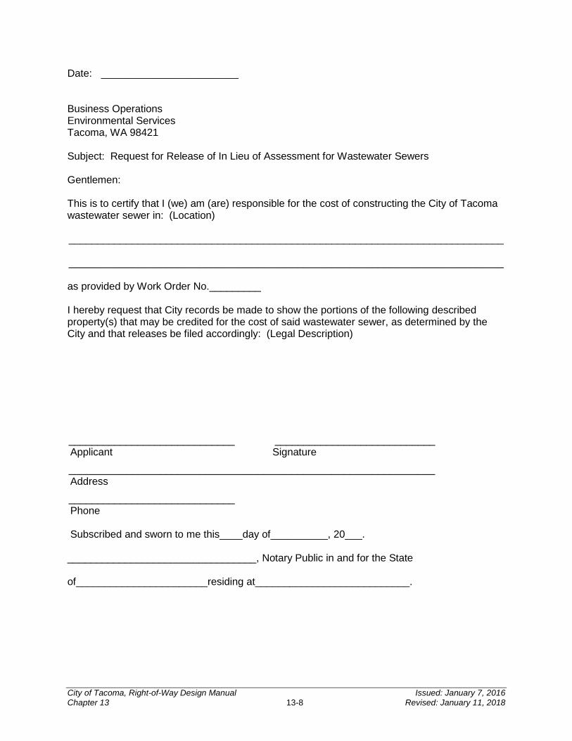
Date: ________________________ Business Operations Environmental Services Tacoma, WA 98421 Subject: Request for Release of In Lieu of Assessment for Wastewater Sewers Gentlemen: This is to certify that I (we) am (are) responsible for the cost of constructing the City of Tacoma wastewater sewer in: (Location) ____________________________________________________________________________
____________________________________________________________________________ as provided by Work Order No._________ I hereby request that City records be made to show the portions of the following described property(s) that may be credited for the cost of said wastewater sewer, as determined by the City and that releases be filed accordingly: (Legal Description) _____________________________ ____________________________ Applicant Signature
________________________________________________________________ Address
_____________________________ Phone Subscribed and sworn to me this____day of__________, 20___.
_________________________________, Notary Public in and for the State
of_______________________residing at___________________________.
City of Tacoma, Right-of-Way Design Manual Issued: January 7, 2016 Chapter 13 13-8 Revised: January 11, 2018

Attachment 13-3: Special Traffic Control Requirements
SPECIAL TRAFFIC CONTROL REQUIREMENTS
LOCATION: Project Vicinity (6000000####)
The following special traffic controls shall supplement Section 1-07.23 of the Standard Specifications.
The contractor may close non-arterial streets to through traffic, provided that local access is maintained at all times with a minimum of a 20 foot wide access lane. The contractor shall coordinate any closures and cooperate with the various businesses and/or residences adjacent to the project site. A minimum of one access shall be maintained to all properties at all times.
Three (3) working days prior to any street closure, the contractor shall notify:
Tacoma Public Works Engineering Division (253) 591-5500 Tacoma Public Works Streets and Grounds (253) 591-5495 Tacoma Environmental Services Solid Waste (253) 591-5544 Tacoma Fire Department (253) 591-5733 Tacoma Police Department (253) 591-5951 LESA Communication Center (253) 798-4721 – Option 3 Tacoma Public Schools Transportation Office (253) 571-1853 Pierce Transit (253) 581-8109
ADDITIONAL REQUIREMENTS:
A. XXXX Street shall remain fully open to vehicular and pedestrian traffic at all times. EXCEPTION: XXXX Street may be reduced by the contractor to a minimum of one lane flagger controlled between the hours of - a.m. and - p.m.
B. YYYY Street shall remain fully open to vehicular and pedestrian traffic at all times. EXCEPTION: YYYY Street may be reduced to a minimum of one lane each direction for two way traffic between the hours of - a.m. and - p.m.
City of Tacoma, Right-of-Way Design Manual Issued: January 7, 2016 Chapter 13 13-9 Revised: January 11, 2018
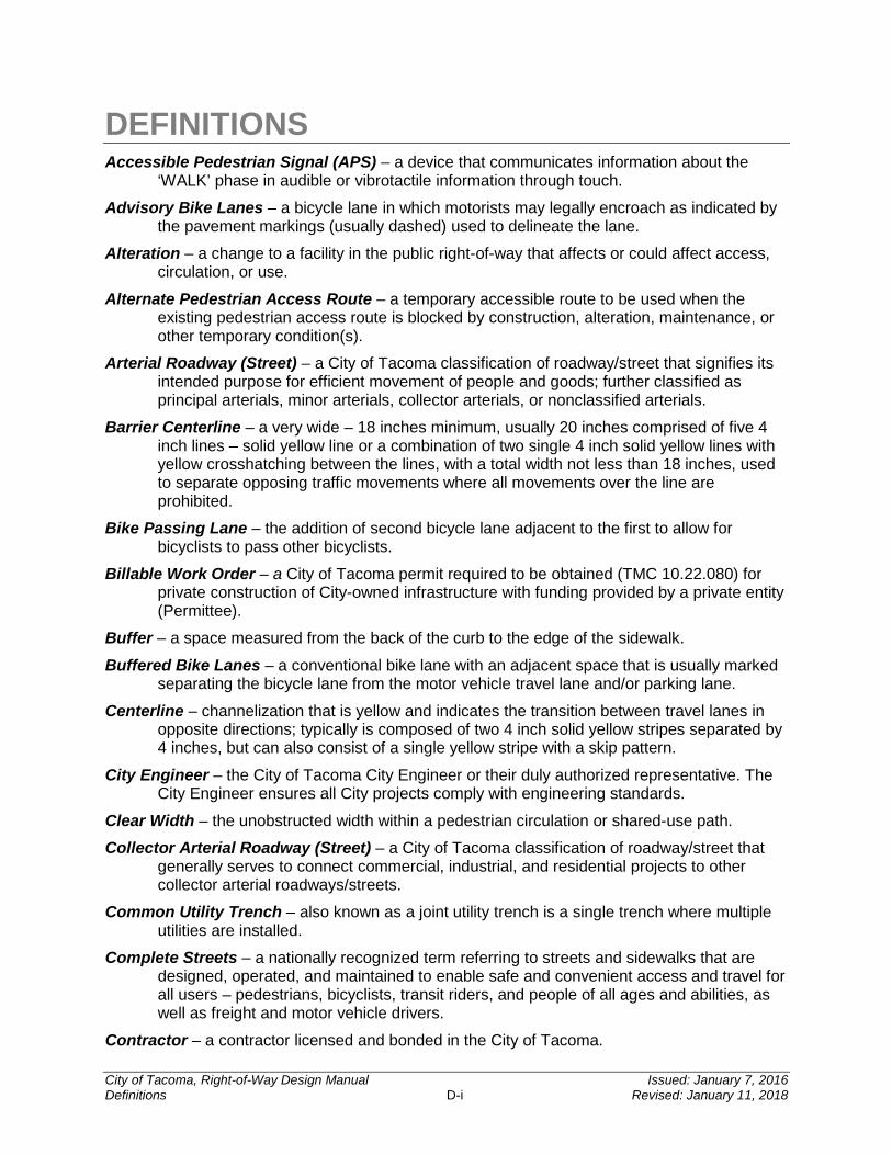
DEFINITIONS Accessible Pedestrian Signal (APS) – a device that communicates information about the
‘WALK’ phase in audible or vibrotactile information through touch.
Advisory Bike Lanes – a bicycle lane in which motorists may legally encroach as indicated by the pavement markings (usually dashed) used to delineate the lane.
Alteration – a change to a facility in the public right-of-way that affects or could affect access, circulation, or use.
Alternate Pedestrian Access Route – a temporary accessible route to be used when the existing pedestrian access route is blocked by construction, alteration, maintenance, or other temporary condition(s).
Arterial Roadway (Street) – a City of Tacoma classification of roadway/street that signifies its intended purpose for efficient movement of people and goods; further classified as principal arterials, minor arterials, collector arterials, or nonclassified arterials.
Barrier Centerline – a very wide – 18 inches minimum, usually 20 inches comprised of five 4 inch lines – solid yellow line or a combination of two single 4 inch solid yellow lines with yellow crosshatching between the lines, with a total width not less than 18 inches, used to separate opposing traffic movements where all movements over the line are prohibited.
Bike Passing Lane – the addition of second bicycle lane adjacent to the first to allow for bicyclists to pass other bicyclists.
Billable Work Order – a City of Tacoma permit required to be obtained (TMC 10.22.080) for private construction of City-owned infrastructure with funding provided by a private entity (Permittee).
Buffer – a space measured from the back of the curb to the edge of the sidewalk.
Buffered Bike Lanes – a conventional bike lane with an adjacent space that is usually marked separating the bicycle lane from the motor vehicle travel lane and/or parking lane.
Centerline – channelization that is yellow and indicates the transition between travel lanes in opposite directions; typically is composed of two 4 inch solid yellow stripes separated by 4 inches, but can also consist of a single yellow stripe with a skip pattern.
City Engineer – the City of Tacoma City Engineer or their duly authorized representative. The City Engineer ensures all City projects comply with engineering standards.
Clear Width – the unobstructed width within a pedestrian circulation or shared-use path.
Collector Arterial Roadway (Street) – a City of Tacoma classification of roadway/street that generally serves to connect commercial, industrial, and residential projects to other collector arterial roadways/streets.
Common Utility Trench – also known as a joint utility trench is a single trench where multiple utilities are installed.
Complete Streets – a nationally recognized term referring to streets and sidewalks that are designed, operated, and maintained to enable safe and convenient access and travel for all users – pedestrians, bicyclists, transit riders, and people of all ages and abilities, as well as freight and motor vehicle drivers.
Contractor – a contractor licensed and bonded in the City of Tacoma.
City of Tacoma, Right-of-Way Design Manual Issued: January 7, 2016 Definitions D-i Revised: January 11, 2018

Contraflow Bike Lanes – bicycle lanes that are marked by design to permit bicyclists to travel in the opposite direction of the motor vehicle flow.
Counter Slope – the slope of the gutter or roadway at the foot of a curb ramp or landing where it connects to the roadway, measured along the axis of the running slope extended.
Cross Slope – the slope measured perpendicular to the direction of travel.
Crosswalk – a marked or unmarked pedestrian crossing, typically at an intersection, that connects the pedestrian access routes on opposite sides of a roadway.
Crosswalk Line – white pavement marking lines that identify a pedestrian crossing when utilized in a series.
Cul-de-sac – a residential street characterized by a single ingress and egress.
Curb Extension – a curb and sidewalk bulge or extension out into the parking lane used to decrease the length of a pedestrian crossing and increase visibility for the pedestrian and driver. Also known as a bulb out.
Curb Ramp – a combined ramp and landing to accomplish a change in level at a curb. This element provides street and sidewalk access to pedestrians with mobility impairments.
Cycle Tracks – a bicycle facility that is exclusively for bicyclists and physically separated from motor vehicle traffic and distinct from any sidewalk.
Deficiency List – a list developed at the time of substantial completion that itemizes all remaining work tasks that must be performed before a project reaches final acceptance.
Detectable Warning Surface – A tactile surface feature of truncated dome material built into or applied to the walking surface to alert persons with visual impairments of vehicular ways.
Development Conditions – the requirements for development of a site set forth by the City of Tacoma.
Design Engineer – the professional civil engineer licensed in the State of Washington who prepares the analysis, design, and engineering plans for an applicant’s permit or approval submittal.
Dotted Extension Line – a broken white or yellow line that is an extension of an edge line or centerline used at intersections, multiple turn lanes, and other locations where the direction of travel for through traffic is unclear.
Dual-Faced Curbing – curbing that has sloped faces which can be installed in between lanes of travel in order to aid in restricting turns to and from access points/streets or for channelizing the flow of traffic
Easement – legal right to use a described piece of land for a particular purpose. It does not include fee ownership, but may restrict the owner’s use of the land.
Edge Line/Stripe – channelization that typically defines the right-side of a travel lane (when the stripe is white) adjacent to the edge of pavement but other applications can also include defining the left-side of a travel lane (when the stripe is yellow), and defining an on-street parallel parking lane.
Erosion – the wearing away of the land surface by running water, wind, ice, or other geological agents, including such processes as gravitational creep. Also, detachment and movement of soil or rock fragments by water, wind, ice or gravity.
Excavation – the mechanical removal of earth material.
City of Tacoma, Right-of-Way Design Manual Issued: January 7, 2016 Definitions D-ii Revised: January 11, 2018
Flangeway Gap – the gap for the train wheel at a railroad crossing. The space between the inner edge of a rail and the pedestrian crossing surface.
Frontage Improvements – includes, but not limited to, the construction of street, sidewalk, curb and gutter, landscaping, street trees, and wastewater or stormwater facilities on all adjacent City of Tacoma ROW.
Fill – a deposit of earth material placed by artificial means.
Gore Line/Stripe – channelization that is white and used to delineate an exclusive use lane like a left-/right-turn lane; typically is 8 inches wide (e.g., twice the width of a typical lane line).
Grade Break – The intersection of two adjacent surface planes (e.g., roadways, sidewalks, etc.) of different grade.
Grading – any excavating or filling or combination thereof.
Green Stormwater Infrastructure – a set of distributed stormwater best management practices that seek to mimic natural systems and deliver multiple community benefits in addition to stormwater management. Green stormwater infrastructure can be used at a wide range of landscape scales in place of more traditional stormwater control elements to support the principles of Low Impact Development.
Greenroads – a performance metric for quantifying sustainable practices associated with roadway design and construction.
Hazard Trees – those trees which have the potential to cause property damage, personal injury or fatality in the event of a failure. Tree hazards include dead or dying trees, dead parts of live trees, or unstable live trees (due to structural defects or other factors) that are within striking distance of people or property (a target).
Improvement – streets (with or without curbs or gutters), sidewalks, crosswalks, parking lots, water mains, wastewater and stormwater pipes, stormwater facilities, street trees and other appropriate items.
Land Use Action – action taken by the City of Tacoma when a variance, special use permit, rezone, plat, or other land use permit is requested by the applicant typically resulting in a set of conditions for approval.
Land Use Administrator – the City of Tacoma Land Use Administrator or their duly authorized representative.
Landing – A level (within ADA compliant allowances) paved area, within or at the top and bottom of a stair or ramp, designed to provide turning and maneuvering space for wheelchair users and as a resting place for pedestrians.
Lane Line/Stripe – channelization that is white and defines the width and number of travel lanes; pattern can include gaps in between solid striping or completely solid; typically is 4 inches wide (certain applications with respect to bike lanes warrant a 6 inch width).
Load Zone – a designated space reserved for the exclusive use of vehicles during the loading or unloading of property.
Low Impact Development – a stormwater and land use management strategy that strives to mimic predisturbance hydrologic processes of infiltration, filtration, storage, evaporation and transpiration by emphasizing conservation, use of onsite natural features, site
City of Tacoma, Right-of-Way Design Manual Issued: January 7, 2016 Definitions D-iii Revised: January 11, 2018
planning, and distributed stormwater management practices that are integrated into a project design.
Maximum Extent Feasible – from the U.S. Department of Justice, 28 CFR Part 36.402: the phrase “to the maximum extent feasible” applies to “the occasional case where the nature of an existing facility makes it virtually impossible to comply fully with applicable accessibility standard through a planned alteration.”
Midblock Pedestrian Crossing – A marked pedestrian crossing located along a roadway between intersections.
Overflow Infiltration Gallery – a shallow depressed area lined with stream cobbles that allows for minor amounts of stormwater ponding in order for stormwater to recharge into the adjacent permeable ballast; collects overflow water from a permeable surface or gutter pan, and is intended for small contributing areas.
Passenger Load Zone – a designated space reserved for the exclusive use of vehicles while receiving or discharging passengers to/from an associated curb ramp.
Pavement Marking – a colored marking applied to the pavement to provide drivers with guidance and other information.
Pavement Paint – specially formulated material for use on roadways; typically sprayed or rolled onto the pavement surface at a thickness specified by the project; either waterborne- or solvent-based composition.
Pedestrian Access Route – a continuous, unobstructed walkway within a pedestrian circulation path that provides accessibility.
Pedestrian Circulation Path – a prepared exterior or interior way of passage provided for pedestrian travel; includes independent walkways, shared-use paths, sidewalks, and other types of pedestrian facilities.
Pedestrian Facilities – walkways such as sidewalks, walking and hiking trails, shared-use paths, pedestrian grade separations, crosswalks, and other improvements provided for the benefit of pedestrian travel. Pedestrian facilities are intended to be accessible routes.
Pedestrian Overpass or Underpass – a grade-separated pedestrian facility, typically a bridge or tunnel structure over or under a major highway or railroad that allows pedestrians to cross.
Pedestrian Refuge Island – an area within the roadway that physically separates the directional flow of traffic, provides pedestrians with a place of refuge, and reduces the crossing distance.
Pedestrian Signal – an adaptation of a conventional traffic signal installed at established pedestrian crossings. It is used to provide a protected phase for pedestrians by terminating the conflicting vehicular movements to allow for pedestrian crossings.
Performance Bond – a surety instrument in which the faithful performance of a contractor is guaranteed up to the face value of the bond.
Permit – a document issued by Planning and Development Services Division allowing construction as identified by said document in accordance with all applicable approved drawings and specifications.
Planting Strip – that portion of the street section between the sidewalk and the edge of the driving surface. The dimension of the planter strip is defined from the edge of the driving surface to the front of walk.
City of Tacoma, Right-of-Way Design Manual Issued: January 7, 2016 Definitions D-iv Revised: January 11, 2018
Private Accessway – any access serving two or more lots located in a private easement, which is owned and maintained by a private owner, group of private owners or neighborhood association.
Project – the proposed action to construct improvements.
Proof Rolling – a process in which a loaded vehicle drives slowly over the compacted subgrade of roadway being constructed in order to indicate areas of insufficient compaction.
Raised Median – a raised area in the center of a road, usually defined by curbing, used to restrict vehicle left turns and side street access.
Record Drawings – drawings based upon as-built conditions of all construction items.
Regulated Trees – those trees which are located within the public ROW and are subject to the standards for management as required by Tacoma Municipal Code and this Design Manual.
Residential (Local) Roadway (Street) – a City of Tacoma classification of roadway/street that constitutes all other roadways not classified as an arterial roadway/street.
Right-of-way – land reserved and secured to the public for the purpose of public improvements to the City of Tacoma infrastructure.
Running Slope – a slope measured in the direction of travel.
Shared Lane Markings (Sharrows) – road markings used to inform road users that the lane (or portion thereof) is intended for shared use by bicycles and automobiles.
Side Sewer, Private – the sewage conveyance pipe owned by the property owner that extends from approximately two feet outside of a building or structure to the connection point at the public sanitary sewer main. In most circumstances, a portion of the private side sewer extends into public streets or alleys connecting to the public sewer main.
Sidewalk Café – a permitted area within the public ROW consisting of tables and/or chairs where patrons may purchase or be served food and/or beverages from an adjacent café or restaurant.
Stop Line/Bar – shall consist of solid white line (a minimum of 12 inches wide) extending across approach lanes to indicate the point at which a vehicle is intended or required to stop.
Street – an arterial or residential street located in public ROW owned and maintained by the City of Tacoma.
Street Furniture – sidewalk equipment or furnishings including trash receptacles, benches, parking meters, artwork, and signage.
Street Lighting – illumination of the traveled way designed and constructed in accordance with current Illuminating Engineering Society of North America (IES) standards.
Thermoplastic – specially formulated material for use on roadways that is a mixture of glass beads, pigments, binder, and filler materials that when heated becomes liquid to facilitate application; either hydrocarbon- or alkyd-based composition.
Traffic Calming – roadway design techniques that have been shown to reduce traffic speeds and unsafe maneuvers.
City of Tacoma, Right-of-Way Design Manual Issued: January 7, 2016 Definitions D-v Revised: January 11, 2018
Transitional Segments – segments of a pedestrian circulation path that blend between existing undistributed pedestrian facilities and newly altered pedestrian facilities.
Two-Way Left-Turn Centerline – two yellow lines, one solid-pattern and one broken-pattern, used to delineate each side of a two-way left-turn lane (TWLTL).
Universal Access – access for all persons regardless of ability or stature.
Walk Interval – that phase of a traffic signal cycle during which the pedestrian is to begin crossing, typically indicated by a ‘WALK’ message or the walking person symbol and its audible equivalent.
Walkway – the continuous portion of the pedestrian access route that is connected to street crossings by curb ramps.
Wastewater Sewer, Public – those portions of the Municipal Sewer System which are designated by the Director to carry, treat, or dispose of wastewater not constituting storm or surface water permitted by or under TMC 12.08 to enter the Municipal Sewer System. Wastewater sewers are also referred to and have the same definition as sanitary sewers, wastewater pipes, and are part of the wastewater system or wastewater conveyance system.
City of Tacoma, Right-of-Way Design Manual Issued: January 7, 2016 Definitions D-vi Revised: January 11, 2018

REFERENCES
American Association of State Highway and Transportation Officials (AASHTO)
http://www.transportation.org/Pages/Default.aspx
American Association of State Highway and Transportation Officials’ A Policy on Geometric Design of Highways and Streets (AASHTO Policy)
https://bookstore.transportation.org/collection_detail.aspx?ID=110
American Association of State Highway and Transportation Officials (AASHTO) Guide for Design of Pavement Structures
https://bookstore.transportation.org/collection_detail.aspx?ID=87
American Association of State Highway and Transportation Officials (AASHTO) Guide for Development of Bicycle Facilities, 4th Edition
https://bookstore.transportation.org/item_details.aspx?ID=1943
Americans with Disabilities (ADA) Standards for Accessible Design
http://www.access-board.gov/guidelines-and-standards/streets-sidewalks
Americans with Disabilities (ADA) Standards for Transportation Facilities
http://www.access-board.gov/guidelines-and-standards/transportation
City of Tacoma Comprehensive Plan – Container Port Element
http://cms.cityoftacoma.org/Planning/Comprehensive%20Plan/15%20-%20Container%20Port%207-22-14.pdf
City of Tacoma Comprehensive Plan – Downtown Element
http://cms.cityoftacoma.org/Planning/Comprehensive%20Plan/14%20-%20Downtown%206-14-11.pdf
City of Tacoma Comprehensive Plan – Tacoma 2040
http://www.tacoma2040.com/adopted-plan.html
City of Tacoma General Special Provisions
www.cityoftacoma.org/designmanual
City of Tacoma, Right-of-Way Design Manual Issued: January 7, 2016 References R-i Revised: January 11, 2018
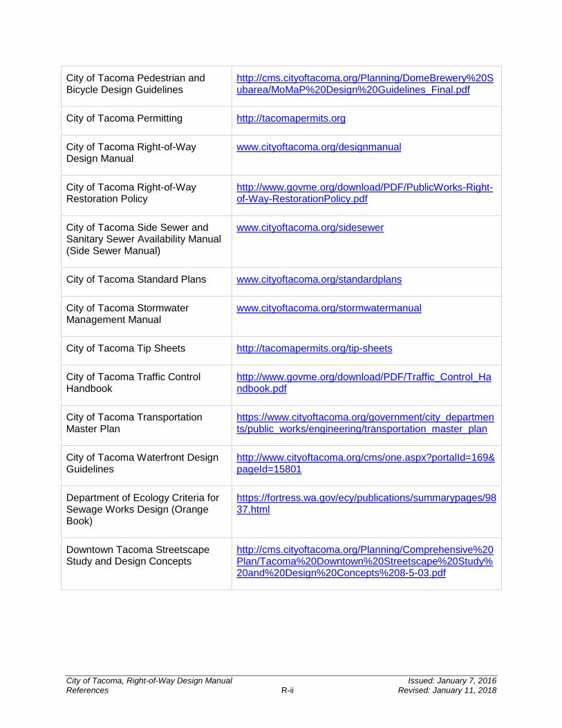
City of Tacoma Pedestrian and Bicycle Design Guidelines
http://cms.cityoftacoma.org/Planning/DomeBrewery%20Subarea/MoMaP%20Design%20Guidelines_Final.pdf
City of Tacoma Permitting http://tacomapermits.org
City of Tacoma Right-of-Way Design Manual
www.cityoftacoma.org/designmanual
City of Tacoma Right-of-Way Restoration Policy
http://www.govme.org/download/PDF/PublicWorks-Right-of-Way-RestorationPolicy.pdf
City of Tacoma Side Sewer and Sanitary Sewer Availability Manual (Side Sewer Manual)
www.cityoftacoma.org/sidesewer
City of Tacoma Standard Plans www.cityoftacoma.org/standardplans
City of Tacoma Stormwater Management Manual
www.cityoftacoma.org/stormwatermanual
City of Tacoma Tip Sheets http://tacomapermits.org/tip-sheets
City of Tacoma Traffic Control Handbook
http://www.govme.org/download/PDF/Traffic_Control_Handbook.pdf
City of Tacoma Transportation Master Plan
https://www.cityoftacoma.org/government/city_departments/public_works/engineering/transportation_master_plan
City of Tacoma Waterfront Design Guidelines
http://www.cityoftacoma.org/cms/one.aspx?portalId=169&pageId=15801
Department of Ecology Criteria for Sewage Works Design (Orange Book)
https://fortress.wa.gov/ecy/publications/summarypages/9837.html
Downtown Tacoma Streetscape Study and Design Concepts
http://cms.cityoftacoma.org/Planning/Comprehensive%20Plan/Tacoma%20Downtown%20Streetscape%20Study%20and%20Design%20Concepts%208-5-03.pdf
City of Tacoma, Right-of-Way Design Manual Issued: January 7, 2016 References R-ii Revised: January 11, 2018
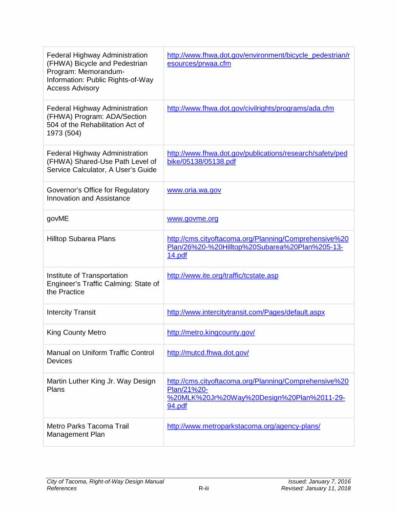
Federal Highway Administration (FHWA) Bicycle and Pedestrian Program: Memorandum-Information: Public Rights-of-Way Access Advisory
http://www.fhwa.dot.gov/environment/bicycle_pedestrian/resources/prwaa.cfm
Federal Highway Administration (FHWA) Program: ADA/Section 504 of the Rehabilitation Act of 1973 (504)
http://www.fhwa.dot.gov/civilrights/programs/ada.cfm
Federal Highway Administration (FHWA) Shared-Use Path Level of Service Calculator, A User’s Guide
http://www.fhwa.dot.gov/publications/research/safety/pedbike/05138/05138.pdf
Governor’s Office for Regulatory Innovation and Assistance
www.oria.wa.gov
govME www.govme.org
Hilltop Subarea Plans http://cms.cityoftacoma.org/Planning/Comprehensive%20Plan/26%20-%20Hilltop%20Subarea%20Plan%205-13-14.pdf
Institute of Transportation Engineer’s Traffic Calming: State of the Practice
http://www.ite.org/traffic/tcstate.asp
Intercity Transit http://www.intercitytransit.com/Pages/default.aspx
King County Metro http://metro.kingcounty.gov/
Manual on Uniform Traffic Control Devices
http://mutcd.fhwa.dot.gov/
Martin Luther King Jr. Way Design Plans
http://cms.cityoftacoma.org/Planning/Comprehensive%20Plan/21%20-%20MLK%20Jr%20Way%20Design%20Plan%2011-29-94.pdf
Metro Parks Tacoma Trail Management Plan
http://www.metroparkstacoma.org/agency-plans/
City of Tacoma, Right-of-Way Design Manual Issued: January 7, 2016 References R-iii Revised: January 11, 2018
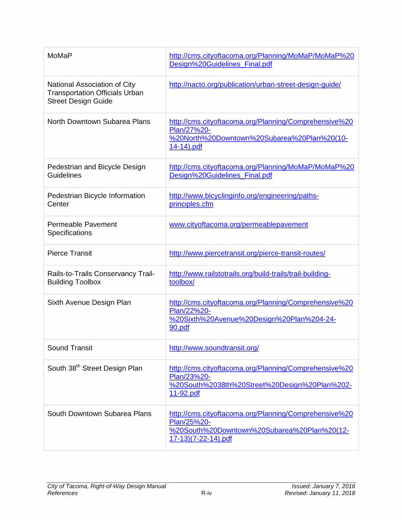
MoMaP http://cms.cityoftacoma.org/Planning/MoMaP/MoMaP%20Design%20Guidelines_Final.pdf
National Association of City Transportation Officials Urban Street Design Guide
http://nacto.org/publication/urban-street-design-guide/
North Downtown Subarea Plans http://cms.cityoftacoma.org/Planning/Comprehensive%20Plan/27%20-%20North%20Downtown%20Subarea%20Plan%20(10-14-14).pdf
Pedestrian and Bicycle Design Guidelines
http://cms.cityoftacoma.org/Planning/MoMaP/MoMaP%20Design%20Guidelines_Final.pdf
Pedestrian Bicycle Information Center
http://www.bicyclinginfo.org/engineering/paths-principles.cfm
Permeable Pavement Specifications
www.cityoftacoma.org/permeablepavement
Pierce Transit http://www.piercetransit.org/pierce-transit-routes/
Rails-to-Trails Conservancy Trail-Building Toolbox
http://www.railstotrails.org/build-trails/trail-building-toolbox/
Sixth Avenue Design Plan http://cms.cityoftacoma.org/Planning/Comprehensive%20Plan/22%20-%20Sixth%20Avenue%20Design%20Plan%204-24-90.pdf
Sound Transit http://www.soundtransit.org/
South 38th Street Design Plan http://cms.cityoftacoma.org/Planning/Comprehensive%20Plan/23%20-%20South%2038th%20Street%20Design%20Plan%202-11-92.pdf
South Downtown Subarea Plans http://cms.cityoftacoma.org/Planning/Comprehensive%20Plan/25%20-%20South%20Downtown%20Subarea%20Plan%20(12-17-13)(7-22-14).pdf
City of Tacoma, Right-of-Way Design Manual Issued: January 7, 2016 References R-iv Revised: January 11, 2018
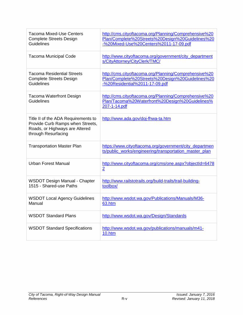
Tacoma Mixed-Use Centers Complete Streets Design Guidelines
http://cms.cityoftacoma.org/Planning/Comprehensive%20Plan/Complete%20Streets%20Design%20Guidelines%20-%20Mixed-Use%20Centers%2011-17-09.pdf
Tacoma Municipal Code http://www.cityoftacoma.org/government/city_departments/CityAttorney/CityClerk/TMC/
Tacoma Residential Streets Complete Streets Design Guidelines
http://cms.cityoftacoma.org/Planning/Comprehensive%20Plan/Complete%20Streets%20Design%20Guidelines%20-%20Residential%2011-17-09.pdf
Tacoma Waterfront Design Guidelines
http://cms.cityoftacoma.org/Planning/Comprehensive%20Plan/Tacoma%20Waterfront%20Design%20Guidelines%207-1-14.pdf
Title II of the ADA Requirements to Provide Curb Ramps when Streets, Roads, or Highways are Altered through Resurfacing
http://www.ada.gov/doj-fhwa-ta.htm
Transportation Master Plan https://www.cityoftacoma.org/government/city_departments/public_works/engineering/transportation_master_plan
Urban Forest Manual http://www.cityoftacoma.org/cms/one.aspx?objectId=64782
WSDOT Design Manual - Chapter 1515 - Shared-use Paths
http://www.railstotrails.org/build-trails/trail-building-toolbox/
WSDOT Local Agency Guidelines Manual
http://www.wsdot.wa.gov/Publications/Manuals/M36-63.htm
WSDOT Standard Plans http://www.wsdot.wa.gov/Design/Standards
WSDOT Standard Specifications http://www.wsdot.wa.gov/publications/manuals/m41-10.htm
City of Tacoma, Right-of-Way Design Manual Issued: January 7, 2016 References R-v Revised: January 11, 2018