Embed Size (px)
Citation preview
2003 CJCS MASTER POSITIONING,
NAVIGATION, AND TIMING PLAN
JOINT STAFF WASHINGTON, D.C. 20318-0600
CJCSI 6130.01C 31 March 2003

(INTENTIONALLY BLANK)
1
CHAIRMAN OF THE JOINT CHIEFS OF STAFF
INSTRUCTION
J-6
CJCSI 6130.01C DISTRIBUTION: S 31 March 2003
2003 CJCS MASTER POSITIONING, NAVIGATION, AND TIMING PLAN
References: See Enclosure K. 1. Purpose. This instruction constitutes the Department of Defense (DOD) plan for use, sustainment, and modernization of positioning, navigation, and timing (PNT) systems to meet operational requirements. This instruction reflects the policy and directions contained in all referenced documents listed in Enclosure K.
a. This plan implements the Chairman of the Joint Chiefs of Staff (CJCS) joint systems responsibilities. It provides the policy and planning basis for DOD PNT requirements, compares requirements to existing technology, identifies performance shortfalls, highlights needed research and development, and provides long-term projections of anticipated capabilities.
b. Service and Defense agencies’ PNT requirements are validated in
accordance with reference a. The resulting validated programs are reflected in this plan and become the basis for Service and Defense agencies’ PNT programming and program objective memorandum (POM) submissions to the Office of the Secretary of Defense (OSD). This master plan also serves as the primary DOD input to the Department of Defense and Department of Transportation (DOT) Federal Radionavigation Plan (FRP) (reference c), Federal Radionavigation Systems (FRS) (reference d), and appropriate North Atlantic Treaty Organization (NATO), bilateral, and multilateral plans. 2. Cancellation. CJCSI 6130.01B, 15 June 2000, “2000 CJCS Master Positioning, Navigation, and Timing Plan (MPNTP),” is hereby canceled. 3. Applicability. This plan applies to the Military Departments, the Chairman of the Joint Chiefs of Staff (Joint Staff), the combatant commands, and the Defense agencies. 4. Policy. DOD policy requires a consistent and logical integration of PNT systems. This includes integrating the data, schedules, programs, plans, and responsibilities for PNT systems among the Services, Defense agencies, and
CJCSI 6130.01C 31 March 2003
2
commands, and between the MPNTP and the FRP and FRS. This plan provides the basis and vehicle for such integration. 5. Definitions. Refer to the Glossary. 6. Responsibilities. See Enclosure A, paragraph 3, sections a through g.
7. Review Procedures. This instruction will be reviewed annually and revised as necessary, normally during odd numbered years. Recommendations for changes from the unified commands should be submitted to the Deputy Director for C4 Systems, J-6, Joint Staff, Washington, D.C. 20318-6000. Service and Defense agency recommendations should be submitted through the following addressees:
a. US Army. Deputy Chief of Staff for Programs, Attn: DAPR-FD, 700 Army Pentagon, Washington, D.C. 20310-0700.
b. US Navy. Navigator of the Navy (N096), US Naval Observatory, Bldg-
1, 3450 Massachusetts Ave NW, Washington, D.C. 20392-5421. c. US Air Force. Director of Operational Capability Requirements, HQ
USAF, Space Requirements Division (HQ USAF/XORR), 1480 Air Force Pentagon, Washington, D.C. 20330-1480.
d. US Marine Corps. Commandant of the Marine Corps, Attn: C4
Department, CS Division, 2 Navy Annex, Washington, D.C. 20380-1775. e. NSA. Director, National Security Agency, Attn: IAD, Ft. George G.
Meade, MD 20755-6000. f. DISA. Director, Defense Information Systems Agency, Attn: DNSO,
D311 DISN Transport Operations Branch, 701 South Courthouse Road, Arlington, VA 22204-2199.
g. NIMA. Director, NIMA, Attn: ST, 4600 Sangamore Road, Bethesda,
MD 20816-5003. 8. Summary of Changes. This instruction has been updated to reflect the merger of United States (US) Strategic Command (USSTRATCOM) and US Space Command (USSPACECOM). Effective 1 October 2002, these organizations officially merged and retain the name USSTRATCOM. This instruction also reflects new GPS user equipment acquisition policy and updates to the current PNT architecture and PNT research and development. 9. Releasability. This instruction is approved for public release; distribution is unlimited. DOD components (to include the combatant commands), other Federal agencies, and the public may obtain copies through the Internet from the CJCS Directives Home Page -- http://www.dtic.mil/doctrine. Copies are
CJCSI 6130.01C 31 March 2003
3
also available through the Government Printing Office on the Joint Electronic Library CD-ROM. 10. Effective Date. This instruction is effective immediately.
For the Chairman of the Joint Chiefs of Staff:
< SIGNED >
Approved & Secured with ApproveITby: JAMES A. HAWKINS, 20 May 2003, 13:19:33
JAMES A. HAWKINS Major General, USAF Vice Director, Joint Staff Enclosures: A -- Positioning, Navigation, and Timing Policy B -- Positioning, Navigation, and Timing Requirements C -- Positioning, Navigation, and Timing System Architecture D -- GPS Operations and Security Policy E -- GPS User Equipment Acquisition Policy and Status F -- Operational PNT Systems -- Descriptions and Characteristics G -- Positioning, Navigation, and Timing Research and Development H -- Control of PNT Systems in Times of Tension or War I -- Geospatial Information and Services J -- Precise Time and Time Interval K -- References GL -- Glossary

4
(INTENTIONALLY BLANK)
CJCSI 6130.01C 31 March 2003
i
DISTRIBUTION Distribution A, B, C, and J plus the following:
Copies Secretary of State ................................................................................. 2 Secretary of Transportation................................................................... 2 Commandant of the Coast Guard........................................................... 2 Assistant Secretary of Defense (Command, Control, Communications, and Intelligence)................................................... 2 Secretary Air Force/US......................................................................... 2 Administrator of the Federal Aviation Administration............................... 2 Director, National Security Agency......................................................... 2 SMC/CC LAAFB, CA............................................................................. 2 Director, Defense Advanced Research Projects Agency ............................. 2 Director, National Reconnaissance Office................................................ 2 Administrator, National Aeronautics and Space Administration....................................................................... 2 Administrator, Defense Technical Information Center .............................. 1 President, National Defense University ................................................... 1 Commandant, Armed Forces Staff College............................................... 2 Director, Office of Management and Budget ............................................ 1 US Delegate to the Military Committee, NATO......................................... 2 Commander, Joint Information Operations Center................................... 1 Air Force Space Command.................................................................... 2 Naval Space Command ........................................................................ 2 Army Space Command ......................................................................... 2 Joint GPS Combat Effectiveness Joint Tests and Evaluation Center ......... 2 Air Force Operational Test and Evaluation Center .................................. 2 Interagency GPS Executive Board........................................................ . 2 Army Test and Evaluation Center .......................................................... 2 Navy Operational Test and Evaluation Force ......................................... .2 Space and Naval Warfare Systems Command ......................................... 2 46th Test Group/746 Test Squadron ..................................................... 2 Secretary of Commerce ........................................................................ 2 US Naval Observatory, Washington........................................................ 2 US Naval Observatory, Flagstaff Station ................................................. 2 USNO Shriever AFB, CO ..................................................................... 2

CJCSI 6130.01C 31 March 2003
ii
(INTENTIONALLY
(INTENTIONALLY BLANK)

CJCSI 6130.01C 31 March 2003
iii
LIST OF EFFECTIVE PAGES
The following is a list of effective pages for CJCSI 6130.01C. Use this list to verify the currency and completeness of the document. A “0” indicates a page in the original document. PAGE CHANGE PAGE CHANGE 1 thru 4 0 F-1 thru F-20 0 i thru vi 0 G-1 thru G-12 0 A-1 thru A-6 0 H-1 thru H-2 0 B-1 thru B-4 0 I-1 thru I-4 0 C-1 thru C-4 0 J-1 thru J-6 0 D-1 thru D-2 0 K-1 thru K-2 0 E-1 thru E-4 0 GL-1 thru GL-6 0

CJCSI 6130.01C 31 March 2003
iv
(INTENTIONALLY BLANK)

CJCSI 6130.01C 31 March 2003
v
RECORD OF CHANGES Change No.
Date of Change
Date Entered
Name of Person Entering Change

CJCSI 6130.01C 31 March 2003
vi
(INTENTIONALLY BLANK)
CJCSI 6130.01C 31 March 2003
A-1 Enclosure A
ENCLOSURE A
POSITIONING, NAVIGATION, AND TIMING POLICY
1. Scope. This master plan documents the DOD policy, requirements, acquisition planning, operational use, and sustainment of PNT systems. It updates the status of all operational DOD PNT systems and the status of DOD PNT acquisition programs. Additionally, this plan describes major military and civilian “common-use” systems and single-Service PNT systems.
a. This plan does not cover every possible topic related to timing, positioning, or navigation. For example, it makes no detailed reference to visual navigation, nor to such topics as use of navigation charts or notices to mariners.
b. This plan uses the term PNT to apply to both the end use of Positioning,
Velocity, and Timing (PVT) information, as well as to the various systems that generate PVT information.
2. Summary of Key PNT Policies
a. General Military Policy. In conducting military operations described in Joint Vision 2020, it is essential that PNT services be available with the highest possible confidence. These services must meet or exceed mission requirements. In order to meet these mission requirements, information that refers to a position on the Earth or in space must indicate that position in terms of the standard geospatial reference frame defined by the World Geodetic System 1984 (WGS-84) as provided by the National Imagery and Mapping Agency (NIMA). Any information that makes reference to time must be able to provide that time in terms of the standard temporal reference defined by Coordinated Universal Time (UTC) as maintained by the US Naval Observatory (USNO) Master Clock, which is the standard for military systems. This UTC (USNO) is the real-time realization of UTC as determined by the International Bureau of Weights and Measures in France. Military operators may make use of a mix of independent, self-contained, and externally referenced PNT systems provided that these systems can be traced directly to the DOD reference standards WGS-84 and UTC (USNO). DOD PNT users may use civil PNT systems for peacetime operations where the use of civil PNT systems does not jeopardize DOD’s ability to carry out its military mission. Only DOD-approved PNT systems will be used for combat, combat support, and combat service support operations. DOD ships and aircraft may use civil PNT system(s) in peacetime scenarios. If civil PNT systems are used, it is highly recommended that the system(s) in use meet International Maritime Organization (IMO), International Civil Aviation Organization (ICAO), and/or FAA specifications.
b. Survivability Requirements. PNT systems must be as survivable and
robust as the forces and weapon systems they are designed to support. The services should use physical security, hardening, electronic protection
CJCSI 6130.01C 31 March 2003
A-2 Enclosure A
mechanisms, and other measures to ensure the availability of PNT services to the United States and its allies, while denying such capabilities to enemies.
c. Continuity. Current PNT systems must be sustained until follow-on
systems have been validated for operational use. d. Need for Periodic Reviews. The Department of Defense will conduct
periodic reviews of emerging PNT technologies to determine their ability to meet operational requirements.
e. Global Positioning System (GPS). GPS is now and will continue to be the
primary radionavigation system source of PNT information for the Department of Defense. All DOD combatant users must acquire, train with, and use GPS systems capable of receiving the encrypted, military GPS signal, the Precise Positioning Service (PPS). While Standard Positioning Service (SPS) is not generally authorized for military use, the Assistant Secretary of Defense for Command, Control, Communications and Intelligence (ASD (C3I)) will consider waiver requests submitted by Service acquisition executives for use of SPS user equipment in specific platforms or application categories that do not involve combat, combat support, or combat service support missions (i.e., test and evaluation, survey, training, etc.). The National Defense Authorization Act for FY 1994 (Public Law 103-160), as amended by National Defense Authorization Act for FY 1999 (Public Law 105-261), mandates that “after September 30, 2005, funds may not be obligated to modify or procure any Department of Defense aircraft, ship, armored vehicle, or indirect-fire weapon system that is not equipped with a Global Positioning System receiver.” DOD PNT users may use civilian GPS augmentations for peacetime operations where such use does not jeopardize carrying out military missions. Examples include the US Coast Guard’s Differential GPS (DGPS), the FAA’s Wide Area Augmentation System (WAAS) and Local Area Augmentation System, currently under development. It is essential for users to understand that these systems may not be reliable during conflict, as they do not incorporate the same level of security and survivability as military systems.
(1) It is imperative that DOD users incorporate properly keyed PPS receivers unless a waiver to use SPS is obtained from the office of the ASD (C3I).
(2) Any DOD system incorporating or using GPS SPS without a waiver from the office of ASD (C3I) will be considered noncompliant with the GPS Security Policy, 29 March 1999 (Reprint 28 February 2002).
f. Command, Control, Communications, Computers, Intelligence, Surveillance, and Reconnaissance (C4ISR) Systems Timing Policy. C4ISR systems that rely on GPS for timing shall use only secure PPS receivers and incorporate the capability to operate without continuous GPS availability or integrity. 3. Responsibilities. The responsibilities of DOD organizations for PNT systems are delineated in DOD Directive 4650.5 (reference b), as modified by Deputy
CJCSI 6130.01C 31 March 2003
A-3 Enclosure A
Secretary of Defense John J. Hamre memo dated 8 September 1998 [reference j]. Additional responsibilities are as follows:
a. The Chairman of the Joint Chiefs of Staff (CJCS) is responsible for DOD PNT operational matters. These functions include:
(1) Developing joint PNT operational doctrine and tactics for use of PNT equipment.
(2) Reviewing Service budgets to ensure appropriate funding of
validated PNT requirements, to avoid duplication of effort, and to prevent needless expenditure of funds on systems scheduled to be phased out.
(3) Promoting standardization, interoperability, and compatibility to
fulfill common requirements. (4) Coordinating PNT matters affecting NATO and individual nations. (5) Providing direction and inputs for the development of a navigation
systems architecture that describes operating concepts, system developments, replacement plans, and alternatives for satisfying validated requirements.
(6) Participating in PNT committees and working groups, as required. (7) Preparing, reviewing, and publishing the CJCS MPNTP in
coordination with the ASD (C3I), the Under Secretary of Defense for Acquisition, Technology, and Logistics [USD (AT&L)], and the Military Departments.
(8) The Joint Staff will approve operational concepts and plans that
establish PNT security requirements and procedures.
b. Within their respective commands, combatant commanders perform functions of the same general nature as those of the CJCS, including planning for the operational employment of PNT systems in war and contingency plans. Combatant commanders may develop PNT requirements in support of contingency plans and CJCS-directed or CJCS-coordinated exercises that require not only their own but also other PNT resources. Combatant commanders are also responsible for reviewing the CJCS MPNTP, suggesting changes, establishing requirements, and implementing the plan.
c. Commander, US Strategic Command (CDRUSSTRATCOM), will operate
GPS as described in reference g. PPS will be operated in accordance with reference f. The SPS will be operated in accordance with reference e. The decision to alter SPS performance to introduce intentional errors will be made by the President and the Secretary of Defense after recommendation by the CJCS following a request by a Combatant Commander. In addition, CDRUSSTRATCOM will operate and maintain the GPS Support Center (GSC), which provides problem reporting and resolution and mission planning support to the Department of Defense. CDRUSSTRATCOM will advocate funding for the GSC and exercise GSC command and control (C2) through the 14th Air Force
CJCSI 6130.01C 31 March 2003
A-4 Enclosure A
(50th Space Wing). The GSC is currently manned during normal duty hours (Mountain Standard Time), Monday through Friday. After hours anomalies and issues should be reported to USAF Space Command’s 24-hour Air Operations Center, located at Vandenberg AFB, California.
d. The Air Force serves as the executive agent that buys, builds, and
controls the GPS satellite constellation.
(1) Air Force Space Command’s Space and Missile Systems Center (SMC) at Los Angeles Air Force Base, CA, is the center of technical excellence for researching, developing and purchasing military space systems.
(2) The NAVSTAR GPS Joint Program Office (JPO) is a joint service effort directed by the US Air Force and managed at the SMC, Air Force Space Command, Los Angeles Air Force Base, California. The JPO is the DOD acquisition office for developing and producing GPS satellites, ground systems, and military user equipment. The GPS constellation is operated and controlled by the 50th Space Wing’s (Air Force Space Command) 2nd Space Operations Squadron, Schriever Air Force Base, CO.
(3) Under Secretary of the Air Force is responsible for all space matters. e. NIMA is responsible for Geospatial Information and Services (GI&S)
support to DOD navigation systems. The support includes charts, digital terrain elevation data (DTED), digital feature analysis data, digital hydrographic chart data, point-positioning data bases, geodetic surveys, the World Geodetic System 1984 (WGS 84), Digital Vertical Obstruction File (DVOF), and associated tables that are compatible with and meet the accuracy objectives approved by the CJCS. GI&S support also includes geodetic positioning of transmitters for electronic systems and tracking stations for satellite systems, maintenance of GPS fixed site operations, digital gravity data supporting high accuracy Inertial Navigation Systems (INS), and generation and distribution of GPS precise ephemeris. NIMA serves as the primary point of contact with the civil community on matters relating to geodetic uses of DOD navigation systems and provides calibration support for certain airborne navigation systems.
f. The National Security Agency (NSA) is responsible for the development
and maintenance of GPS cryptography. The NSA also develops devices and techniques used to deny the unauthorized use of PNT systems information. NSA is responsible for educating all other DOD agencies on actual and suspected PNT cryptographic vulnerabilities. NSA will develop all key management architectures for GPS and will assist in the developing or certifying of all GPS crypto key-loading devices.
g. The US Navy, through the US Naval Observatory (USNO), is responsible
for establishing and maintaining the astronomical reference frame(s) for celestial navigation and orientation of space systems. The USNO provides star catalogs, Earth orientation parameters, almanacs, software products, and data services to meet DOD operational needs for navigation. The US Navy, through the USNO, is also responsible for deriving and maintaining standards for
CJCSI 6130.01C 31 March 2003
A-5 Enclosure A
Precise Time and Time Interval (PTTI) and ensuring uniformity in PTTI operations. Coordinated Universal Time (UTC) (USNO), as determined by the Master Clock at USNO, is the DOD time standard. The output of the Master Clock is the reference for the master control of GPS.
h. The Interagency GPS Executive Board (IGEB) is responsible for the
management of the dual use aspect of GPS and it’s US government-provided augmentations. The IGEB is co-chaired by the ASD (C3I) and the Assistant Secretary for Transportation Policy (from the Department of Transportation). Other US government agencies making up the IGEB membership include the Departments of State, Commerce, Agriculture, Interior, and Justice; National Aeronautics and Space Administration; the US Air Force, and the Joint Staff. The IGEB is tasked to manage GPS and its US government-provided augmentations. Functions of the IGEB include reviewing the status and plans for continued development, acquisition, and operations of GPS affecting dual use, approving management policies, resolving interdepartmental issues, preparing periodic status reports for the President, and consulting with US government agencies, US industry, and foreign governments on issues involving GPS.

CJCSI 6130.01C 31 March 2003
A-6 Enclosure A
(INTENTIONALLY BLANK)
CJCSI 6130.01C 31 March 2003
B-1 Enclosure B
ENCLOSURE B
POSITIONING, NAVIGATION, AND TIMING REQUIREMENTS
1. General Requirements. It is DOD policy to develop, procure, and sustain PNT systems to meet the full spectrum of military operations. It is also DOD policy that military platforms conducting peacetime operations will conform to applicable rules to ensure interoperability and transparency within domestic and international controlled airspace, on the high seas, and on coastal and inland areas. To meet operational requirements, the ideal PNT system should have the following characteristics:
a. Worldwide coverage.
b. User-passive.
c. Capable of denying and degrading use by adversaries while not impacting friendly military operations or unduly disrupting civil users.
d. Able to support an unlimited number of users.
e. Resistant to countermeasures. Systems should be as survivable and
endurable as the forces and weapon systems they support including hostile attack, electromagnetic pulse (EMP), and natural disturbances.
f. Possess system integrity. g. Reliable.
h. Real-time response.
i. Interoperable among DOD Services and allied and/or coalition partners.
j. Free from frequency allocation problems.
k. Common grid or map datum reference for all users.
l. Common time reference for all users.
m. Accuracy that is not degraded by changes in location, altitude, high-“G”
or other violent maneuvers, weather, complex terrain masking, or by time of year or day.
n. Maintainable by 5-skill level maintenance personnel at the user’s
location.
o. Self-contained.
CJCSI 6130.01C 31 March 2003
B-2 Enclosure B
p. Availability not limited by weather, altitude, complex terrain masking, structures, or depth of water.
q. Provide four-dimensional information (i.e., x, y, z and time).
r. Certifiable for applications involving civil airspace operations.
2. Operational Survivability Requirements. PNT systems must be as survivable and enduring as the forces and weapon systems they are designed to support. Terrestrial-based systems, such as: Tactical Air Navigation (TACAN), Microwave Landing System (MLS), Instrument Landing System (ILS), etc., should employ physical security measures that reduce vulnerability to sabotage or terrorist attack. Rapid reconstitution plans, including plans for replacement transmitters, use of rugged construction techniques, and conventional and nuclear hardening, should be considered. Space-based systems must be hardened against electromagnetic pulse (EMP) to at least the same level as the forces the system supports. Transmission and reception techniques to minimize jamming and other interference must be employed. Additionally, methods need to be employed to minimize hostile exploitation of PNT systems and to deny use of such systems to military adversaries or other combatants. Physical security measures must be in place to minimize the impact of attempts to destroy or incapacitate satellite ground control segments. 3. Aviation Requirements
a. Aircraft must be equipped with instruments and navigation equipment appropriate to the routes to be flown. The FAA issues Technical Standard Orders that prescribe minimum performance standards for navigation equipment used by the civil aviation community in the National Airspace System (NAS). The ICAO issues standards and recommended practices (SARPS) for international civil aviation. The development of minimum performance standards for military users is the responsibility of the Services. These military standards must conform with civil airspace required navigation performance requirements, prevent violation of civil air traffic clearances, and ensure safe separation of military and civil air traffic. While meeting the ICAO SARPS is essential, military combat and combat support aircraft must have PNT capabilities designed to operate in a combat or stressed environment where civil PNT services are likely to be jammed or severely limited. The Department of Defense will consider civil performance standards in determining its aviation navigation needs and certify its PNT equipment for military aviation use.
b. The Department of Defense is in the process of self-certifying PPS for use in the NAS and international airspace. This self-certification will be done to civil standards. The Department of Defense also will work with military establishments of its international allies as well as the ICAO to seek approval for use of PPS in foreign airspace. Self-certification of PPS will reduce the amount of equipage on military aircraft. It will provide an enhanced capability to span the operational environment for military aviation from flight in civil airspace in peacetime to combat operations worldwide.
CJCSI 6130.01C 31 March 2003
B-3 Enclosure B
c. With the exception of the Army-validated WAAS requirement documented in the Global Air Traffic Management (GATM) Operational Requirements Document (ORD), approved 9 April 2001, the Department of Defense does not have an operational requirement for WAAS. Therefore, it does not plan to equip all military aircraft with WAAS. Implementation of WAAS will be performed on a limited number of military airframes on a case-by-case basis as necessary. These airframes could include the Civil Reserve Air Fleet (CRAF) if the commercial operators elect to equip with WAAS. National Guard, Reserve Component aircraft, and civil-derivative military aircraft may consider utilizing WAAS if there are demonstrated benefits at the civil airports where these aircraft operate.
d. The Department of Defense does not have an operational requirement to
use the L5 signal. Therefore, it does not plan to equip all military aircraft with L5 capability. Implementation of L5 will be performed on a limited number of military airframes on a case-by-case basis. These airframes could include the CRAF if commercial operators elect to use L5; National Guard and Reserve Component aircraft if there is a demonstrated benefit from L5 at civil airports where these aircraft operate from; and civil-derivative military aircraft that might include L5 as normal equipment.

CJCSI 6130.01C 31 March 2003
B-4 Enclosure B
(INTENTIONALLY BLANK)
CJCSI 6130.01C 31 March 2003
C-1 Enclosure C
ENCLOSURE C
POSITIONING, NAVIGATION, AND TIMING SYSTEM ARCHITECTURE
1. General. Currently no single ideal PNT system exists to support all DOD PNT requirements as outlined in Enclosure B. Therefore, the DOD PNT architecture summarized in this enclosure consists of a mix of PNT systems. Until such time as a single, ideal system can be identified, developed, and fielded to meet all operational requirements, a mix of systems will continue to be required. 2. Architecture. The DOD PNT architecture consists of systems that are used in combat and combat support operations and systems that support worldwide peacetime operations. The challenge for the Department of Defense is to minimize the costs to equip platforms to operate in both environments while eliminating the necessity to maintain duplicative systems.
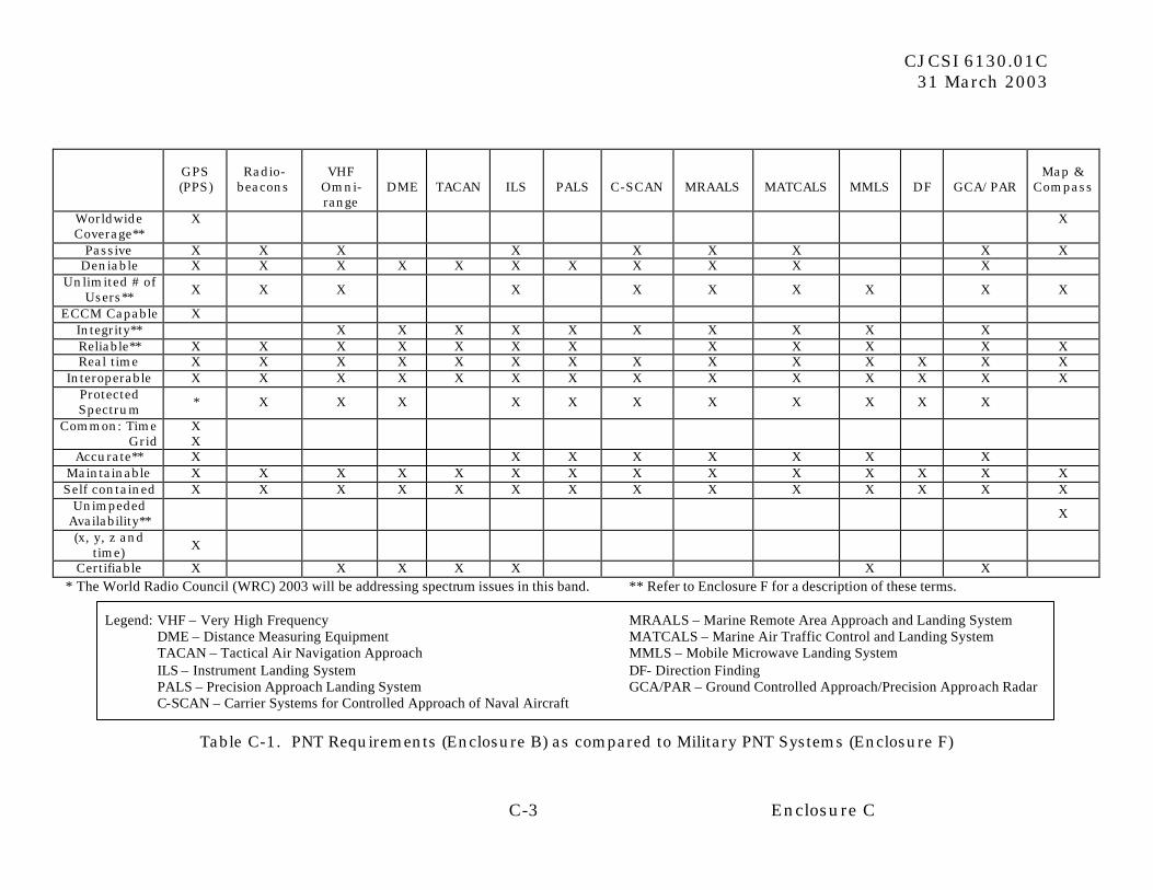
a. Combat and Combat Support Operations. Table C-1 lists the externally
derived [e.g., does not address INS] PNT systems that may be used for combat and combat support operations and cross references these systems with the PNT requirements from Enclosure B. Details of the systems in Table C-1 are contained in Enclosure F.
b. Non-combat Operations. The FRP and FRS contain descriptions of
federally provided PNT systems that are available for non-combat applications for DOD platforms. To minimize duplication of information contained within the current FRP and FRS, these systems are not listed here. Department of Defense users are reminded of the policy as stated in Enclosure A, subparagraph 2a, on the use of civil PNT systems for combat and non-combat operations.
3. Current PNT Systems Architectures. The DOD PNT architecture consists of a mix of PNT systems, as no single PNT system meets all of DOD’s operational requirements. However, GPS is now and will continue to be the primary radionavigation system source of PNT information for the Department of Defense. Enclosure F contains details on each PNT system that is currently part of the DOD PNT architecture.
4. Future PNT Systems Architectures. Determination of what PNT systems are to be maintained to fulfill DOD requirements is a function of the mission criticality being served by a specific PNT system, the redundancy requirements necessary to conduct a DOD mission, and costs (operations and maintenance).
a. As GPS is now and for the foreseeable future will continue to be the primary radionavigation system source of PNT information for the Department of Defense, it has become an area of significant focus. On 16 June 1999, the Joint Requirements Oversight Council (JROC) approved the GPS ORD and validated the key performance parameters (KPP). (See Enclosure K.) The JROC
CJCSI 6130.01C 31 March 2003
C-2 Enclosure C
confirmed that the KPPs will provide the operational capability necessary for GPS to satisfy the mission needs. The ORD was signed 22 February 2000. This ORD is the basis for space and control segment modernization and will be a guide for future Service and Defense Agency user equipment designs and budget submissions. The GPS ORD undergoes continuous review and the next revision is expected in 2004. These new validated requirements will help ensure the modernization of GPS meets new and expanding military and civil requirements. Details on GPS modernization initiatives are located in Enclosure G. Please reference Enclosure K for GPS ORD information.
b. Another area receiving significant focus today is the development of a
system architecture to equip DOD platforms with the capabilities to fly in controlled airspace using GPS. The Deputy Chief of Staff, Air & Space Operations (AF/XO) has the DOD lead in evaluating what must be done to use the GPS PPS in controlled airspace. Efforts are currently underway to ensure that PPS receivers can be certified to enable operations in controlled airspace. The Army and Air Force GATM architectures represent the effort to ensure appropriate aircraft comply with FAA and/or ICAO communications, navigation, surveillance, and air traffic management requirements. Implementing this architecture will involve significant investment by the Department of Defense. The Navy has a similar program to ensure compliance with FAA and/or ICAO requirements and refers to it as Communication Navigation Surveillance/Air Traffic Management (CNS/ATM).
CJCSI 6130.01C 31 March 2003
C-3 Enclosure C
GPS (PPS)
Radio-
beacons
VHF
Omni-range
DME
TACAN
ILS
PALS
C-SCAN
MRAALS
MATCALS
MMLS
DF
GCA/PAR
Map &
Compass
Worldwide Coverage**
X X
Passive X X X X X X X X X Deniable X X X X X X X X X X X
Unlimited # of Users** X X X X X X X X X X
ECCM Capable X Integrity** X X X X X X X X X X Reliable** X X X X X X X X X X X X Real time X X X X X X X X X X X X X X
Interoperable X X X X X X X X X X X X X X Protected Spectrum * X X X X X X X X X X X
Common: Time Grid
X X
Accurate** X X X X X X X X Maintainable X X X X X X X X X X X X X X Self contained X X X X X X X X X X X X X X
Unimpeded Availability** X
(x, y, z and time) X
Certifiable X X X X X X X * The World Radio Council (WRC) 2003 will be addressing spectrum issues in this band. ** Refer to Enclosure F for a description of these terms.
Legend: VHF – Very High Frequency MRAALS – Marine Remote Area Approach and Landing System
DME – Distance Measuring Equipment MATCALS – Marine Air Traffic Control and Landing System TACAN – Tactical Air Navigation Approach MMLS – Mobile Microwave Landing System ILS – Instrument Landing System DF- Direction Finding PALS – Precision Approach Landing System GCA/PAR – Ground Controlled Approach/Precision Approach Radar C-SCAN – Carrier Systems for Controlled Approach of Naval Aircraft
Table C-1. PNT Requirements (Enclosure B) as compared to Military PNT Systems (Enclosure F)

CJCSI 6130.01C 31 March 2003
C-4 Enclosure C
(INTENTIONALLY BLANK)
CJCSI 6130.01C 31 March 2003
D-1 Enclosure D
ENCLOSURE D
GPS OPERATIONS AND SECURITY POLICY
1. Policy. The Military Services, Joint Staff, combatant commands, and Defense agencies will comply with established policies (references f and h). 2. Summary. The Department of Defense operates the GPS PPS to provide a military advantage for the United States and its allies. At the same time, GPS SPS is available for peaceful civil, commercial, and scientific use on a continuous, worldwide basis, free of direct user fees. The Department of Defense intends to prevent the adversary use of GPS during hostilities through its Navigation Warfare (Navwar) program, with a goal of conducting prevention activities without unduly interfering with the peaceful use of GPS outside combat areas. DOD, allied, and friendly foreign military GPS users will use the PPS to ensure exclusive use of the full capability of GPS. 3. Procedures for Altering Selective Availability (SA) .
a. At midnight on 1 May 2000, SA was set to zero, in compliance with the President’s announcement that the United States would stop the intentional degradation of the GPS. A military request to change the GPS operating mode or alter the SPS accuracy level will originate with a combatant commander. It will be addressed to the Chairman of the Joint Chiefs of Staff and include the Secretary of Defense and CDRUSSTRATCOM as information addressees. A decision to degrade SPS accuracy or to change the GPS operating mode must be approved by the President of the United States or his designated representative. If time and circumstances permit, the Department of Defense will consult with the Secretary of Transportation and the other cabinet secretaries. Civil users will be notified via the Notice to Airmen (NOTAM) and Notice to Mariners (NOTMAR) systems. DOD agencies will forward requests for operating mode changes to the Chairman of the Joint Chiefs of Staff via the Joint Staff in peacetime scenarios with a minimum of 90 days advance notice. Defense agencies should send information copies of these requests to the Under Secretary of the Air Force, the USD (AT&L), the Assistant Secretary for Transportation (Policy), and CDRUSSTRATCOM. Non-DOD agencies will forward requests for SA/anti-spoof (SA/A-S) status changes to the Assistant Secretary for Transportation (Policy). In peacetime scenarios, USSTRATCOM will ensure a minimum of thirty (30) days advance notice of GPS operational mode changes is given to all users. Sixty (60) days advance notice will be the goal.
b. Some proponents in the Department of Defense and civil sector are
advocating deleting SA entirely from GPS III. This proposal will be vetted at the IGEB.
4. DOD Differential Policy. The Department of Defense will operate insofar as possible using the PPS received directly from the GPS satellite constellation as
CJCSI 6130.01C 31 March 2003
D-2 Enclosure D
the primary source of PNT information. Additionally, the Department of Defense is considering methods to improve the direct reception accuracy available from PPS to satisfy high-precision positioning, timing, and navigation needs in authorized military platforms without requiring differential corrections. To the extent the Department of Defense uses differential GPS for combat operations, the differential systems must use the PPS, and the differential corrections must be encrypted for transmission and processing. DOD PNT users may use US civil DGPS systems for peacetime operations where their use does not jeopardize DOD ability to carry out its military mission. Use of foreign DGPS systems that are not provided by countries with defense arrangements with the Department of Defense are prohibited. The preceding prohibitions do not apply to ships and aircraft in peacetime navigation scenarios as long as the system(s) in use are IMO or ICAO recognized systems, respectively.
a. The Department of Defense plans to deny access to coarse/acquisition (C/A) code signals, C/A code-derived DGPS, and other precise PNT systems in local combat theaters or other areas of national security interest.
b. DOD GPS users may use civilian-provided SPS-based DGPS services
when civil agencies define navigation accuracy, integrity, availability, and continuity of service requirements that exceed direct reception PPS capabilities, where operation is in the interest of the DOD, and where such use will not adversely affect military missions. 5. Selective Availability/Anti Spoofing Module (SAASM) Policy. DOD policy requires the use of SAASM in all newly fielded systems, as well as, systems going through major modification or upgrade. The SAASM architecture will replace (over time) the existing legacy PPS Security Module (PPS-SM) architecture. Although the force retrofit from legacy PPS-SM devices to SAASM devices is not currently mandated, the ability to obtain the red keys necessary to support legacy devices may become problematic over the next 12 to 15 years. Even though SAASM devices are designed to accept red key or black key, for security, delivery and cost reasons, the Joint Staff desires the transition from red key to black key as soon as possible. The current Joint Staff target for transitioning is CY15 through CY18. After vetting through the Joint Requirements Oversight Council (JROC), specific direction on a planned key transition will be contained in the updated releases of policy documents (references f and h located in Enclosure K of this document).
CJCSI 6130.01C 31 March 2003
E-1 Enclosure E
ENCLOSURE E
GPS USER EQUIPMENT ACQUISITION POLICY AND STATUS 1. Objective . The objectives of the DOD user equipment acquisition policy are to:
a. Support employment of GPS as the primary radionavigation system and standard source for accurate time and time synchronization for use by all forces.
b. Preserve the US military competitive advantage and maintain force
enhancement capabilities derived from direct access to the GPS-PPS.
c. Promote the purchase of user equipment from competitive sources that have been technically and security pre-qualified by NSA and the GPS JPO.
d. Preclude duplication of user equipment development efforts and
associated costs by concentrating the development of common military user equipment at the GPS JPO.
e. Ensure DOD airborne users conform to the performance requirements
for operation within the NAS and within the ICAO airspace.
f. Facilitate the expedient acquisition and/or utilization of GPS-PPS timing signals by weapons systems.
2. Acquisition Policy
a. In the previous edition of this document, the GPS JPO was identified as the lead organization for development and procurement of GPS user equipment (UE) to avoid duplication of effort and strive for common UE for all the military services. However, technology is now driving us in the direction of modular-based GPS capabilities, embedding GPS receiver functionality into multipurpose avionics and other platform electronics, and a centralized procurement strategy may no longer offer the best value to DOD users. This technology evolution dictates a change in policy, implementing an open system architecture for GPS UE using a defined set of physical, functional, and security standards. To this end, ASD (C3I) is contemplating a revision to the GPS UE acquisition policy as follows:
(1) GPS JPO shall:
(a) Establish and identify a set of physical, functional, and security
standards for GPS UE that meet the requirements in the GPS ORD.
CJCSI 6130.01C 31 March 2003
E-2 Enclosure E
(b) Establish the process to approve and/or certify that GPS receivers, GPS receiver cards, or modules developed by industry conform to the applicable GPS JPO physical, functional, and security performance standards.
(c) Establish and maintain a vendor base of qualified suppliers
from which the services may procure modular receiver equipment suitable for their respective platforms and missions.
(d) Establish a security design review process.
(2) Platform or host system program director and/or manager shall:
(a) Continue to perform the GPS integrator role for their platforms.
(b) Procure only GPS UE conforming to JPO approved and/or
certified physical, functional, and security performance standards built by JPO approved and/or certified vendors.
(c) Following coordination with NIMA on WGS84 and Datum
issues, request waivers from the JPO Director where common GPS approved and/or certified UE will not satisfy their unique host system requirements.
b. GPS user equipment intended for use on DOD aircraft operating in civil
airspace will meet established NAS and ICAO performance standards. The JPO will ensure that GPS user equipment procured or developed through the JPO for aviation applications will satisfy the certification requirements for operations in civil airspace. Actual certification of the GPS user equipment will be performed by the JPO and certification of aircraft navigation capability will be performed by the Services. 3. GPS Equipment Status. Section 152(b) of the National Defense Authorization Act for Fiscal Year 1994 (Public Law 103-160; 107 Stat. 1578) placed limitations on procurement of systems not GPS equipped. This mandate, termed GPS 2000, prohibited obligation of funds to modify or procure any DOD aircraft, ship, armored vehicle, or indirect-fire weapon system not equipped with a GPS receiver after 30 September 2000. The National Defense Authorization Act for Fiscal Year 1999 (Public Law 105-261) extended the 30 September 2000 date to 30 September 2005. Equipping all affected DOD platforms is occurring at varying rates. Most DOD platforms are currently equipped with legacy, red keyed, GPS receivers. Many other platforms are in the process of adding legacy, red keyed, GPS receivers.
a. SAASM is the “next generation” of GPS cryptography and UE developed to decrease GPS vulnerabilities and implement new capabilities. All newly fielded DOD systems will use SAASM compliant PPS devices no later than 1 October 2006. A GPS UE roadmap will act as a SAASM compliance document (until 1 October 2006) for the Army, Navy, Air Force and Marines. Other DOD agencies that utilize legacy GPS PPS devices must provide their SAASM transition plan directly to ASD (C3I). Non-DOD agencies that utilize PPS are urged to comply with the spirit of this instruction. SAASM waiver requests for
CJCSI 6130.01C 31 March 2003
E-3 Enclosure E
non-SAASM equipment entering the field after 1 October 2006 shall be submitted from the service acquisition executive to ASD (C3I). C3I will approve and/or disapprove these waiver requests after consulting with the Joint Staff (J-6).
b. SAASM implements the Joint Staff and NSA requirement to transition the United States (and its allies) from classified red keys to unclassified black keys as soon as possible. SAASM delivers black keys, improved anti-tamper, and new “Over the Air” capabilities much sooner than the new military code (M-Code) (which is currently in development). SAASM became available for DOD procurement in 2002.
c. DOD SPS Use. There is a growing number of military users relying on
SPS within Department of Defense. Unauthorized SPS use minimizes US government and allied efforts to implement new cryptography and user equipment developed to decrease GPS vulnerabilities and implement new capabilities (i.e., SAASM). Per reference f, Chapter 3, “Systems used for combat, combat support, or combat service support missions must use PPS-capable GPS receivers operating in the Precise Positioning System (PPS) mode.” Commanders or directors unable to comply must first obtain a waiver from ASD (C3I) before operating with SPS receivers. The Joint Staff (J-6) will be consulted before granting waivers to use SPS. Any PPS shortfalls (legacy or SAASM) must be addressed in UE roadmaps and service and/or agency annual budget submissions.

CJCSI 6130.01C 31 March 2003
E-4 Enclosure E
(INTENTIONALLY BLANK)
CJCSI 6130.01C 31 March 2003
F-1 Enclosure F
ENCLOSURE F
OPERATIONAL PNT SYSTEMS -- DESCRIPTIONS AND CHARACTERISTICS 1. General. This enclosure describes the characteristics of operational PNT systems currently used by the Military Services and DOD agencies. Two general categories of PNT systems are described:
a. PNT systems that use radiated signals from an external PNT source for navigation or relative bearing and distances determination.
b. Self-contained PNT systems that do not require reception of externally
generated signals and can provide capabilities that may not be available from radionavigation systems in a hostile environment. Major PNT system requirements that have universal use are discussed using the parameters addressed in Enclosure B. Special or limited-use systems are described briefly and information regarding system performance parameters has been included where practical. Current or deployed systems are discussed in this enclosure. Developing systems are discussed in Enclosure G. GPS is now and will continue to be the primary radionavigation system source of PNT information for the Department of Defense. As GPS is more fully utilized, a number of the PNT systems listed in this enclosure will be phased out. For some PNT systems in this category, a target date to begin or complete “phase-out” is provided.
2. PNT System Performance Parameters. Systems described in this plan are defined in terms of system performance parameters that determine their use and limitations. A description of these parameters follows.
a. Accuracy. Accuracy is the degree of conformance between the estimated or measured navigation, positioning, or timing output parameter of a platform at a given time and its true navigation, positioning, or timing output parameter. Because accuracy is a statistical measure of performance, a statement of the accuracy of a navigation system must include a statement concerning the probability level of the estimate or measurement. Specifications of PNT system accuracy generally refer to one or more of the following definitions:
(1) Geodetic Accuracy. The accuracy of a position with respect to the
known (surveyed) geodetic coordinates of points on the Earth.
(2) Geodetic Repeatable Accuracy/Precision. The level of repeatability with which a user can determine position with respect to a position whose coordinates have been measured at a previous time with the same navigation system.
(3) Geodetic Relative Accuracy. The accuracy with which a user can
measure position relative to that of another user of the same navigation system at the same time or to some reference point such as a beacon or buoy. Relative accuracy may also be expressed as a function of the distance between the two users. For example, a GPS-equipped aircraft might use the geodetic solution of
CJCSI 6130.01C 31 March 2003
F-2 Enclosure F
another GPS receiver, located near a runway, as the destination or objective during an approach to landing.
(4) Time Transfer Accuracy. Time transfer accuracy is the measure of
agreement between a locally produced time and a standard time reference source. For DOD operations, the standard source is UTC as maintained by the USNO (UTC (USNO)).
b. Availability. The availability of a PNT system is the percentage of time
that the services of the system are usable. This is a function of both the physical characteristics of the environment and the technical capabilities of the transmitter. Availability is also an indication of the system’s ability to provide usable service within the specified coverage area. Signal availability is the percentage of time that navigational signals transmitted from external sources are available for use. To consider a system available for aviation use in civil controlled airspace, the system must meet both accuracy and integrity requirements.
c. Coverage. The coverage provided by a PNT system is that surface area or
space volume in which the signals are adequate to permit the user to determine position and time to a specified level of accuracy. Coverage is influenced by signal availability which varies based upon system geometry, signal power levels, receiver sensitivity, atmospheric noise conditions, and other factors (i.e., double or triple canopy jungle).
d. Reliability. The reliability of a PNT system is a function of the frequency
with which failures occur within the system. It is the probability that a system will perform its function within defined performance limits for a specified period of time under given operating conditions. Formally, reliability is one minus the probability of system failure.
e. Integrity. Integrity is the ability of a PNT system to provide timely
warnings to enable a user to determine when the system should not be used for PNT to support the mission or phase of operation.
f. Fix Rate. Fix rate is defined as the number of independent position fixes
or data points available from the system per unit of time.
g. Fix Dimensions. This characteristic defines whether the navigation system provides a one-dimensional line of position (LOP), or a two- or three-dimensional position fix. The ability of the system to derive the fourth dimension (time) from the navigation signals is also included.
h. System Capacity. System capacity is the number of users a system can
simultaneously accommodate.
i. Ambiguity. Ambiguity exists when the PNT system identifies two or more possible positions of the vehicle, with the same set of measurements, with no indication of which is the most nearly correct position. The potential for system
CJCSI 6130.01C 31 March 2003
F-3 Enclosure F
ambiguities should be identified along with a provision for users to identify and resolve them.
j. Continuity of Service. Continuity of Service is a civil aviation term that is
defined as the probability that the navigation accuracy and integrity requirements will be supported throughout a flight operation or flight hour given that they are supported at the beginning of the flight operation or flight hour and that the flight operation is initiated and predicated on the operation of the service. 3. Radionavigation Systems
a. Global Positioning System (GPS)
(1) Description. The GPS is a space-based positioning, velocity, and time distribution radionavigation system. GPS is divided into three segments --the space segment, control segment, and user segment. The nominal GPS satellite constellation consists of 24 satellites. Each satellite generates a navigation message based upon data periodically uploaded from the control segment and adds the message to a 1.023 MHz Pseudo-Random Noise (PRN) C/A code and a 10.23 MHz precise code (encrypted) (P(Y)) code sequence. The satellite modulates the resulting code sequences onto a 1575.42 MHz L-band carrier (L1) to create a spread-spectrum ranging signal. Also, each satellite transmits the navigation message and the P (Y), also known as the “ Y-code” at 1227.6 MHz (L2). The satellite design requires frequent updates via interaction with the ground and allows all but a few maintenance activities to be conducted without interruption to the ranging signal broadcast. The GPS Control Segment is composed of these major components: a Master Control Station (MCS), a Back-Up Master Control Station (BMCS), 4 dedicated ground antennas (GA), and 6 dedicated monitor stations (MS). The MCS is located at Schriever Air Force Base, Colorado, and is the central control node for the GPS satellite constellation. Operations are maintained 24 hours a day, 7 days a week throughout each year. The BMCS is located at a contractor facility in Maryland. A fully functional Alternate MCS is being built at Vandenberg AFB, CA. The MCS is responsible for all aspects of constellation C2, to include:
(a) Routine satellite bus and payload status monitoring.
(b) Satellite maintenance and anomaly resolution.
(c) Monitoring and management of GPS performance in support of
all performance standards.
(d) Navigation data upload operations as required to sustain performance in accordance with accuracy performance standards.
(e) Prompt detection of and response to service failures.
(2) Accuracy. Performance requirements are specified in the current
GPS ORD, dated February 2000. Not all ORD requirements are fully satisfied
CJCSI 6130.01C 31 March 2003
F-4 Enclosure F
by the current system. Per the current ORD, military navigation user equipment shall provide position accuracy, (Terrestrial Service Volume), at any location, 95 percent of the steady state observations sampled over 30 days at times when the system is available an accuracy with an error no greater than 6.3 meters (m) horizontal and 13.6 m vertical threshold. This is representative of 3 m circular error probable and a projected (future) User Range Error (URE) of 1.5 m (root mean square (rms)) (1.25 [rms] contribution from the Space Segment and Control Segment and 0.8m (rms) contribution from the user equipment.). The objective position accuracy shall have an error no greater than 1 m (95 percent) horizontal and 4 m (95 percent) vertical.
(3) Coverage. Coverage is the terrestrial service volume and/or space
service volume in which GPS service is provided. The coverage area includes all latitudes and longitudes on or above the Earth to geosynchronous altitude and consists of two service volumes with different performance requirements.
(a) Terrestrial Service Volume. From the Earth’s surface up to and including 3,000 km altitude.
(b) Space Service Volume. From 3,000 km altitude above the Earth’s surface up to and including 36,000 km altitude above the Earth’s surface.
(4) Availability. Availability is the percentage of time that the specified GPS position accuracy will be available to a user at any location in the coverage volume. Availability depends mainly on the number and the distribution of GPS satellites utilized and assumes a nominal URE from each satellite. The constellation has been maintained at 24, or more, healthy satellites approximately 91 percent of the time since full operational capability. Availability at any point within the terrestrial service volume shall be greater than or equal to 90 percent over any 24-hour period (threshold) and 99.9 percent (objective). (These figures are based on the simultaneous loss of signal from the two most critical GPS SVs, measured at any point on Earth, and a steady state URE of 1.5 m [rms)).
(5) Time Transfer Accuracy. System Level Time Transfer, the accuracy of the GPS transfer of UTC is measured at the Master Clock of the United States, which is located at the USNO. The USNO calculates the accuracy and delivers it to the Operational Control Segment (OCS). The OCS maintains accurate time transfer by calculating GPS time, calculating individual space vehicle (SV) corrections to GPS time, and uploading corrections into the SV databases for subsequent re-broadcast to users. The OCS maintains a steady state time transfer accuracy of the GPS signal to an error of less than or equal to 20 nanoseconds (nsec) (95 percent) relative to UTC (USNO) (threshold) and 10 nsec (95 percent) relative to UTC (USNO) (objective).
b. Radio Beacons (1) Description. Radio beacons are non-directional transmitting
stations that operate in the low frequency (LF) and medium frequency (MF)
CJCSI 6130.01C 31 March 2003
F-5 Enclosure F
bands. A radio direction finder is used to measure the relative bearing to the transmitter with respect to the heading of an aircraft or vessel. Aeronautical non-directional beacons (NDB) operate in the 190 to 415 kHz and 510 to 535 kHz bands. Marine radio beacons operate in the 285 to 325 kHz band. The transmissions include a continuous carrier wave (CCW) or modulated continuous wave (MCW) signal to identify the station. The CCW signal is generated by modulating a single carrier with either a 400-hertz (Hz) or 1,020 Hz tone for Morse Code identification. The MCW signal is generated by spacing two carriers either 400 Hz or 1,020 Hz apart and keying the upper carrier to give Morse code identification. Some of the long-range marine radio beacons operate on the same frequency and are time sequenced to prevent mutual interference.
(2) Accuracy. Accuracy of the bearing information is a function of geometry of the line of positions (LOP), compass heading, measurement accuracy, distance from the transmitter, stability of the signal, nature of the terrain between beacon and craft, and noise. Bearing accuracy is about:
+3 to +10 degrees Aeronautical +3 degrees Marine
(3) Coverage. High-power aeronautical LF beacons provide reliable
ground wave capability in excess of 560 km during favorable weather conditions. Marine beacons normally cover an area out to 50 nm or the 100 fathom curve.
c. Very High Frequency (VHF) Omnidirectional Range (VOR)
(1) Description. VOR is a ground-based radionavigation system used
for en route, terminal, and non-precision approach air navigation. In most areas of the world, VOR is used as the primary navigation aid for transiting nationally designated airways. VOR stations operate in the VHF frequency band of 108 to 118 MHz. At these frequencies, VOR is a line-of-sight system and the distance at which the signals can be received is a function of altitude and of transmitter power. Two signals are transmitted, one fixed and one rotating. The aircraft receiver compares the phase of the signals and produces a readout indicating the magnetic bearing to the station. There are approximately l4,000 military aircraft equipped with VOR receivers.
(2) Accuracy. Predictable user accuracy (using root sum squared-rss
techniques) is ±4.5 degrees, relative accuracy is ±4.3 degrees, and repeatable accuracy is ±2.3 degrees.
(3) Coverage. VOR has line-of-sight capabilities that limit ground coverage to 56 km or less. At altitudes above 1,525 m, the range is approximately 190 km; above 6,100 m, the range will approach 375 km. En route stations radiate approximately 200 watts. Terminal VOR stations are rated at approximately 50 watts and are designed for use within terminal areas.
CJCSI 6130.01C 31 March 2003
F-6 Enclosure F
d. Distance Measuring Equipment (DME)
(1) Description. DME stations are normally collocated with VOR stations to provide the user with distance from the station. The DME interrogator in the aircraft generates a pulsed signal (interrogation) that, with the correct frequency and pulse spacings, is accepted by a ground transponder. In turn, the transponder generates pulsed signals (replies) that are sent back and accepted by the interrogator’s tracking circuitry. Distance is calculated by measuring the total round trip time of the interrogation and the reply. DME operates in the 960 to 1,2l3 MHz frequency band (except 1,030 and 1,090 MHz) with a separation of 1 MHz.
(2) Accuracy. Ground station errors are less than 0.1 nautical mile
(nm). The overall system error [airborne and ground rss] is no greater than 0.5 nm or 3 percent of the distance to the station, whichever is greater. A precision DME working with mobile microwave landing system (MMLS) will provide 30 m (2 drms) accuracy on the last l3 km of an approach.
(3) Coverage. DME is a line-of-sight system that limits ground
coverage to 56 km or less. At altitudes above 1,525 m, the range will approach 190 km. Those stations radiate 1,000 watts. Terminal DMEs radiate 100 watts and are only intended for use in terminal areas.
e. Tactical Air Navigation (TACAN)
(1) Description. TACAN is an airborne, ground- or ship-based radionavigation system that combines the bearing capability of VOR and the distance-measuring function of DME. It uses 252 channels, in the 960-1215 MHz band, the same frequency band as DME. TACAN transmitters are primarily used by military users and are frequently collocated with VOR stations, particularly along federal airways. When TACAN is collocated with a VOR, the collective installation is called a combined VOR/TACAN station (VORTAC). The signal consists of rotating coarse azimuth (15 Hz) and fine azimuth (135 Hz) elements. Reference signals in the form of pulse trains are added to the radiated signal to provide electrical phase. The 135 Hz sine wave signal provides additional accuracy thereby reducing bearing error. Bearing is obtained by comparing the 15 and 135 Hz sine waves with the reference groups. Phase-down of TACAN systems is planned for a future date, yet to be determined. Sea-based TACAN will continue in use until a replacement system is successfully deployed.
(2) Accuracy. The ground station errors are less than ±1.0 degree (+65
m at 3.75 km) in azimuth for the 135 Hz element and ±4.5 degrees (+294 m at 3.75 km) for the 15 Hz element. Distance errors are the same as DME.
(3) Coverage. TACAN has a line-of-sight limitation that restricts
ground coverage to 56 km or less. At altitudes of 1,525 m, the range will approach 190 km; above 5,500 m, the range approaches 245 km. The station output power is 5 kW.
CJCSI 6130.01C 31 March 2003
F-7 Enclosure F
f. Instrument Landing System (ILS)
(1) Description. ILS is a precision approach and landing system consisting of a localizer, a glideslope, and one to three VHF marker beacons. ILS provides vertical and horizontal guidance information during the approach to an airport runway. The localizer facility and antenna are typically located about 305 m beyond the stop end of the runway and transmit a VHF (108-112 MHz) signal. The glideslope facility is located approximately 305 m from the approach end of the runway and transmits an ultra-high frequency (UHF) (328.6-335.4 MHz) signal. Marker beacons are located along the approach extension of the runway centerline. Marker beacons emit 75 MHz signals and indicate to the pilot decision-height points or distance-to-the-runway threshold. The Department of Defense will continue use of ILS until a suitable precision approach replacement is developed followed by an appropriate transition period.
(2) Accuracy. For typical operations at a 3,050 m runway, the course
alignment (localizer) at threshold is maintained within ±7.6 m. Course bends during the final segment of the approach do not exceed ±0.06 degrees. Glideslope course alignment is maintained within ±2.1 m at 30 m elevation and course bends during the final segment of the approach do not exceed ±0.07 degree.
(3) Coverage
Localizer +35 degrees (10 nm) and +10 degrees (18
nm) from runway centerline.
Glideslope Nominally 3 degrees from the horizontal. Transmits a signal 1.4 degrees (1,500 feet (ft)) wide at 10 miles from the runway threshold.
Marker Beacons +40 degrees (approximately) on minor axis (along approach path). +85 degrees (approximately) on major axis.
g. Precision Approach Landing System (PALS) (AN/SPN-42 or 46)
(1) Description. PALS is a carrier-based landing system that operates
in the microwave frequency band (Ka/X Band) and in three modes. Mode 1 is automatic; the system senses deviation from the optimal heading and glideslope and automatically controls the aircraft to touchdown. Mode 2 is pilot controlled; the system transmits deviations to a cockpit instrument. Mode 3 is similar to ground controlled approach (GCA) (see page F-10); in this mode, a shipboard operator transmits instructions to the pilot. Also, there is a Mode 1A operation in which the aircraft is controlled automatically as in Mode 1 until it is one-half mile from the carrier. At that point, automatic control is decoupled and the pilot resumes control of the aircraft.
CJCSI 6130.01C 31 March 2003
F-8 Enclosure F
(2) Accuracy. Azimuth and elevation, ±0.044 degree.
(3) Coverage. The system can be used up to l5 km from the carrier, within ±55 degrees in azimuth, and -l5 to +30 degrees in elevation relative to the landing area.
h. Carrier Systems for Controlled Approach of Naval Aircraft (C-SCAN)
(1) Description. C-SCAN is an aircraft carrier landing system, similar
to ILS. It operates in the microwave frequency band (Ku-Band). Originally designed as an independent monitor for the PALS, C-SCAN can also be used as a primary landing aid. C-SCAN provides azimuth and elevation guidance through the use of a cross pointer display.
(2) Accuracy. Relative accuracy is ±0.1 degree in elevation, ±0.2
degrees azimuth.
(3) Coverage. Approximately 19 km from the carrier (±20 degrees in azimuth, 0 to 10 degrees in elevation.
i. Marine Remote Area Approach and Landing System (MRAALS)
(1) Description. The MRAALS is a two-person transportable, all weather instrument landing system that transmits azimuth and elevation angle data and range data to suitably equipped aircraft. The airborne system translates the data and provides glideslope, localizer, and range and rate information to the pilot indicators. The MRAALS (AN/TPN-30) transmits azimuth and elevation data in the Ku-band frequency range [15.412 to 15.688 gigahertz (GHz)] and DME data in the L-band frequency range (962 to 1213 MHz). It can be set up in one of two configurations; collocated or split site. The collocated site, for landing zones, uses one AN/TPN-30 to provide azimuth, elevation, and range data. The split site, for airfields and airports, uses two AN/TPN-30s -- one at the end of the runway that provides azimuth data, and one parallel to the runway that provides elevation and range data. In the collocated configuration, the AN/TPN-30 can be remotely controlled (up to 1,000 ft) using field wire by the C-10195 and TPN-30 remote control or by the C-10194 and TPN-30 control indicator, which also provides status information. In the split site configuration, the C-10194 and TPN-30 control indicator is used for remote control and for providing status of the two AN/TPN-30s, which are synchronized by field wire.
(2) Accuracy. At 1 km from the station, the azimuth accuracy is ±1.74
m, elevation accuracy is ±0.87 m. Range accuracy degrades as a function of distance and is +70 m at 1 km from the centerline.
(3) Coverage. ±20 degrees in azimuth, 0 to 20 degrees in elevation,
18.5 km from the station.
j. Marine Air Traffic Control and Landing System (MATCALS)
CJCSI 6130.01C 31 March 2003
F-9 Enclosure F
(1) Description. The MATCALS was developed to satisfy the
requirement for a precision traffic control and landing system for Navy and Marine aircraft at expeditionary airfields. MATCALS duplicates the functions of the carrier air traffic control (ATC) center and provides operating space for air traffic and landing controllers plus supporting equipment. Initial MATCALS equipment deliveries consist of the AN/TPN-22 PAR, AN/TSQ-107 Air Surveillance Radar with identification, friend or foe (IFF), and the AN/TSQ-131 Communications Control Subsystem. The AN/TSQ-107 will be replaced by the AN/TPS-73 radar. MATCALS provides PALS mode 1, 2, and 3 landing capability and uses the same airborne equipment as PALS. The existing MATCALS air surveillance radar (ASR), Precision Approach Radar (PAR), and Communications and Control Subsystems will be replaced in the 2004-2007 timeframe with the Air Surveillance and Precision Approach Radar Control System (ASPARCS).
(2) Accuracy. Azimuth, ±3 m at 1 km from aircraft touchdown point.
Elevation, ±2 m at 1 km.
(3) Coverage. Includes ±23 degrees from runway heading and elevation coverage of -1 to +7 degrees. Distance advisories are available on all headings.
k. Mobile Microwave Landing System (MMLS)
(1) Description. The Air Force has developed and deployed 33 MMLSs for contingency operations. The MMLS is being used by USAF C-130s equipped with modified commercial MLS avionics and USAF C-17s equipped with Precision Landing System Receivers (PLSR). The PLSR is a USAF developed multi-mode receiver (MMR) with ILS, MB, MLS, and VOR capability. DGPS is a growth capability currently being developed for the PLSR.
(2) Accuracy. MLS azimuth and elevation accuracy for the split-site
configuration on a 12,000 ft runway is +30 ft and +6 ft, respectively, at the Category II decision height of 100 ft. Azimuth and elevation accuracy for the collocated configuration on any length runway is +65 ft and +15 ft, respectively, at the Category I decision height of 200 ft. Accuracies include allowances for the avionics. The DME transponder accuracy is +33 ft.
(3) Coverage. Data over an area bounded by ±40 degrees from runway
centerline, -0.9 to +15 degrees elevation and up to 15 nm range from the runway threshold.
l. Direction Finding (DF)
(1) Description. Direction finders provide the capability to determine a relative bearing on any UHF radio transmission and are used primarily in ATC and as a backup navigation system, particularly between moving platforms.
(2) Accuracy. Relative accuracy ±3 to 5 degrees.
CJCSI 6130.01C 31 March 2003
F-10 Enclosure F
(3) Coverage. Line-of-sight from the transmitter.
m. Ground Controlled Approach and Precision Approach Radar (GCA/PAR)
(1) Description. GCA has been a precision landing aid for military aircraft since World War II. Ground-based and shipboard precision approach radar provides the operator with aircraft position relative to a fixed approach path. The operator announces aircraft location relative to the glideslope until the pilot has visual contact with the runway or until a minimum altitude is reached. Special aircraft equipment is not required. All voice instructions are passed by standard VHF and UHF radios. GCA/PAR are the NATO standard precision landing systems and are tactically deployable. GCA will remain operational until a suitable replacement is deployed.
(2) Accuracy. Relative accuracy is ±1.3 degrees in azimuth, ±1.1
degrees in elevation, and +60 m in range.
(3) Coverage. Approximately 18.5 km from the runway threshold.
n. Polarfix
(1) Description. Polarfix is a commercial, Gallium Arsenide (GaAs)-Laser (904 nm), range-azimuth, auto tracking, positioning system. Polarfix is used by the Navy for precise positioning on degaussing ranges, and by the Army Corps of Engineers for hydrographic surveys.
(2) Accuracy. +0.5 m +0.01 percent of measured distance.
(3) Coverage. 5 km.
o. Enhanced Position Location Reporting System (EPLRS)
(1) Description. EPLRS is a secure, jam-resistant, low probability of
intercept data communication system that also provides the position of units throughout the network for the purposes of navigation and command and control. The system uses an adaptive method of relaying data between users to provide coverage over a large theater. The receiver/transmitters (R/T) in the system operate over the 420 MHz to 450 MHz range, have output power that can be varied from 400 milliwatts to 100 watts, and use both direct sequence encoding and frequency hopping.
(2) Accuracy. At least three EPLRS R/Ts must have a known position.
From this, all remaining units in the system can calculate their position. The specified geodetic relative accuracy is a 50 percent spherical error probable of 30 m. Testing shows results of about 12 m horizontal circular error probable (CEP) and 4 to 5 m altitude CEP.
(3) Coverage. The area covered by the network will be dependent upon
the number and placement of EPLRS R/Ts in the theater, as well as the terrain
CJCSI 6130.01C 31 March 2003
F-11 Enclosure F
of the area. A flat earth line-of-sight model gives an R/T to R/T range of about 85 km for ground units. Position and data can be relayed from R/T to R/T for up to six hops.
(4) System capacity. Each EPLRS network can have up to 460 R/Ts.
Multiple networks can be used simultaneously.
(5) Fix rate. The fix rate is dependent upon system configuration, but is typically 1 second. 4. Radar Beacons
a. Aircraft
(1) Radar beacons are portable transponders used for targeting aerial bombardment. The beacon transponder is interrogated by an aircraft, and a transmission from the beacon is sent to the aircraft in response to the interrogation. The aircraft radar is then tuned so that only the coded beacon response is displayed on the radar scope. Using an offset bombing mode, the aircraft’s radar crosshairs are placed on the beacon while the aircraft attacks a target that is offset at the prescribed range and bearing from the beacon.
(2) Radar beacons are used when poor terrain features provide
inadequate radar returns for precise radar bombing; on targets that must be attacked within specified times during darkness or bad weather; when there is a lack of time for detailed mission planning and target study; and to facilitate the assignment of targets after an aircraft is airborne. In a low-threat environment, the maximum offset range is within a 15-nm radius of the target and the minimum aircraft altitude is 1,000 feet above ground level. In a high-threat environment, the maximum offset range is within a 5-nm radius of the target and the maximum aircraft altitude is 1,000 feet above the ground. Coverage degradation occurs from heavy foliage or other methods used to conceal the beacon’s presence.
b. Ship. Ship radar beacons are short-range radio devices used to provide
radar reference points in areas where it is important to identify a special location or to mark hazards to navigation. 5. Special Purpose Systems (Self-Initiated)
a. Doppler
(1) Description. Doppler navigation is performed using a Doppler velocity sensor, a heading reference, and a navigation computer. Doppler navigation is dead reckoning in that it tracks changes in position from a known starting point. The Doppler velocity sensor determines aircraft velocity and drift angle by measuring the Doppler frequency shift of reflected energy from narrow radar beams transmitted at oblique angles from the aircraft toward the ground.
CJCSI 6130.01C 31 March 2003
F-12 Enclosure F
(2) Accuracy. 0.1 to 0.3 percent of distance traveled. When a typical attitude and heading reference system is used with an accuracy range of 0.5 to 1.5 degrees, the Doppler navigation system error is almost completely dominated by heading errors and will range from 0.9 percent to 2.6 percent of distance traveled.
(3) Coverage. Global.
(4) Fix Rate. Continuous.
(5) Fix Dimension. Two-dimensional (2-D).
b. Terrain Contour Matching (TERCOM)
(1) Description. TERCOM uses radar and barometric altimetry to
determine a three-dimensional (3-D) position by comparing detected terrain profiles with pre-stored profiles of the terrain being traversed. Position fixes may be used to update INS or Doppler systems. NIMA is producing TERCOM data for use by cruise missiles, and there are development efforts to use the system in strategic bombers and remotely piloted vehicles.
(2) Coverage. Specifically digitized land areas.
(3) Fix Rate. One per digitized update area.
(4) Fix Dimension. 3-D.
c. Bottom Contour Navigation
(1) Description. An echo sounder is used in bottom contour navigation
to determine a submarine position by comparing detected terrain features with bottom contour charts of the sea bottom being traversed. Echo sounders use sonar to detect features of the ocean bottom. Bottom contour information can be used to update an INS or as a direct input to a weapon-launching system.
(2) Accuracy. Radial root-mean-square (rms) accuracy of bathymetric
position-fixing is approximately ±200 m where accurate charts, based on surveys with the requisite accuracy, are available.
(3) Coverage. Coverage has traditionally been limited to areas where
paper charts that depict bathymetric contours are available. NIMA Vector Product Format (VPF) electronic charts currently entering production (these include Digital Nautical Charts (DNC©) and Tactical Ocean Data (TOD) will provide bathymetry information in a database that can be queried. Upgrade of bottom contour navigation aids to utilize VPF electronic charts will result in worldwide coverage.
(4) Fix Dimension. 2-D.
d. Digital Scene Matching Area Correlation (DSMAC).
CJCSI 6130.01C 31 March 2003
F-13 Enclosure F
(1) Description. DSMAC is a target area missile guidance system.
Unlike TERCOM, which is a contour matching system, DSMAC utilizes actual photographs of the target area that are digitized and stored in a computer on board the missile. Missile guidance to the general target area is provided by another system such as TERCOM. Once in the vicinity of the target, DSMAC will match the digitized photograph with the surrounding terrain and correct missile guidance to the target. DSMAC is generally used with conventional weapons that require more accuracy than can be provided by TERCOM alone.
(2) Coverage. Target area only.
6. Self-Contained Systems
a. Inertial Navigation Systems (INS)
(1) Description. Inertial navigation provides covert, accurate, and reliable user platform attitude, position, and velocity information and is capable of worldwide operation over a wide range of velocities, attitudes, and accelerations, regardless of weather or jamming attempts. An INS is a self-contained system that can operate autonomously (e.g., without aids external to the user platform). Before each use, an inertial navigation system must be initialized using known geodetic position and velocity. From a set position, the inertial system provides continuous estimates of position, velocity, and attitude. For all the precision and accuracy of inertial systems, the output is an estimated position and not a fix. Even the best inertial must be updated periodically, as the error grows with time. Errors may be mitigated in high accuracy INS by compensating for the spatial variations in the Earth’s gravitational field. Drift rates for integrated GPS/INS navigation systems with accuracy’s better than ± 0.4 km/hr will benefit significantly from gravity field compensation. The key components of an INS are an inertial measurement unit (IMU), a navigation computer, and a control and display unit. The IMU can consist of either a gyro-stabilized (e.g., gimbaled) or strap-down platform on which inertial instruments, accelerometers, and gyroscopes are mounted. In the strap-down installation, the mounting is on a non-stabilized structure attached to the frame of the vehicle. The navigation computer processes the IMU outputs to generate position, velocity, heading, and attitude data; drive navigation displays; and generate appropriate gyro-torquing commands. Also, the navigation computer provides sequencing functions to properly initialize the IMU before use as a navigator. The control and display unit displays INS data to the user and permits the user to control the INS.
(2) Accuracy. The present standard for a medium accuracy INS
includes the following characteristics.
Aircraft Ship Submarine
CJCSI 6130.01C 31 March 2003
F-14 Enclosure F
Position Drift
+1.85 km/hr
+1.85 km/30 hrs time rms
+1.85 km/14 days time rms
Velocity +0.76 m/sec
+0.21 m/sec
+0.21 m/sec
Attitude +2.50 arc minutes (min) rms
+1.75 arc min rms
+2.00 arc min rms
Heading +9.0 arc min +0.030/hr
+2.00 arc min X secant lat
+2.00 arc min X secant lat
(3) Coverage. Unlimited.
b. Major INS Programs
(1) USAF Standard Navigator. The Air Force has procured a series of
standard inertial systems for wide application in USAF aircraft. After establishing a form, fit, and function specification, which describes the requirements in detail, candidate equipment were tested and qualified at the Central Inertial Guidance Test Facility. Production equipment was then competitively procured from a qualified source. Two procurements of the AN/ASN-141 (INS) were made several years apart, which were installed in A-10A, F-16C/D, HH-60A, FB-111, and EH-60 aircraft. A subsequent procurement was made competitively for the CN-1656/ASN (Litton) and CN-1656A/ASN (Honeywell), which were installed in USAF C-17, C-130, RF/F-4C/D/E series, HH-53, and CV-22. A variant of this system, employing many common parts but packaged in a different form factor, was used on the F-15. Another form of the standard inertial system will be installed in MC-130 E/H, AC-130H, and J-STARS aircraft. The Modular Azimuth Positioning System (MAPS), a derivative of these standard inertial systems, is also being developed to meet Army indirect fire requirements.
(2) Commercial INS. The Air Force and Navy have procured
commercial inertial equipment, designed for use by commercial air carriers and built to ARINC 561 characteristics, for many of their cargo, transport, and patrol aircraft. The advantages of procuring such equipment are no development costs, competitive pricing, state-of-the-art accuracy, high reliability, low operating costs, and widely available service. These systems constitute one-quarter to one-third of the Services’ inventory of inertial systems. Commercial system use is a form of standardization in that ARINC standard inertial systems are form and fit interchangeable. With good planning, software compatibility can be achieved among the various applications so that there is also functional interchangeability between the various aircraft, thereby providing a very broad logistic base.
(3) Carrier Aircraft Inertial Navigation System (CAINS). The Navy has
developed a family of standard CAINS that meet the most stringent
CJCSI 6130.01C 31 March 2003
F-15 Enclosure F
performance, alignment, and environmental requirements of carrier-based aircraft. The first member of this family, the AN/ASN-92 (CAINS I), was installed in the F-14A/B, E-2C, S-3A/B, ES-3A, A-6E, RF-4B, and TC-4C aircraft. The second-generation system, the AN/ASN-130A (CAINS 1A), was installed in the AV-8B, and EA-6B aircraft. The third generation, the AN/ASN-139 (CAINS II), which incorporates ring laser gyro (RLG) technology, has been installed in the F/A-18C/D/E/F, E-2C, C-2A and the F-14D. The fourth generation incorporates both RLG and embedded GPS (Embedded GPS Inertial-EGI). This system is installed in the F/A-18A+, F-14A/B, EA-6B (a dual system), AH-1W and S-3B. The AV-8B plans to replace the existing CAINS IA with CAINS II obtained from the F/A-18A+. The SH-60R/S plans to install dual EGI systems. A fifth generation system, Accurate Navigation (ANAV), is being planned for installation in the F/A-18E/F/G. ANAV will incorporate features of the EGI plus gravity compensation and other process refinements.
(4) Aircraft Carrier Navigation Systems (CVNS). The current system
remaining on a few CV/CVNs consists of 2 AN/WSN-1(V)2 inertial systems, 2 AN/UYK-44 standard digital computers, and 2 CV-2953A(P) signal data converters tied into the MK70 MOD 6 switchboard, which provides the interface between the CVNS and other shipboard equipment. The Navy began upgrading this system with the WSN-7(V)3 ring laser gyro navigator (RLGN) in FY99 which provides improved reliability and maintainability. These systems support aircraft inertial alignment.
(5) Electrically Suspended Gyro Navigation (ESGN). ESGN, AN/WSN-3,
provides precise, self-contained, worldwide inertial navigation for nuclear-powered attack submarine (SSN). The Navy has developed and certified software for ESGN operation with the SSN navigation subsystems. This system is currently being replaced by the WSN-7A(V)1.
(6) AN/WSN-5 Inertial Navigation System. The AN/WSN-5 is currently
being used on Aegis Cruisers (CGN-47 class), Destroyers (DDG-51 class), DD-963, LHA and LHD to provide reference information for weapons launching and for navigation. This system is currently being replaced by the WSN-7(V)1, 2, or 3.
(7) AN/WSN-7 Ring Laser Gyro Inertial Navigation System. The
AN/WSN-7/7(A) employs three RLG and three accelerometers in a strap-down configuration. It provides precise, self-contained, worldwide inertial navigation and is the Navy’s multi-platform navigator replacing the AN/WSN-1, AN/WSN-3, and AN/WSN-5. The RLGN provides significant reliability and maintainability improvement over current systems. In addition, it provides submarine comparable performance at reduced costs and across all platform types.
(8) AN/WSN-7B Ring Laser Gyro Navigator (RLGN). The WSN-7B is a
self-contained system whose IMU employs three RLG and three accelerometers in strap-down configuration. The WSN-7B requires external ship’s speed input and periodic input of position data. While its principal function is to replace existing gyrocompasses (e.g., AN/WSN-2/2A, MK-19), it has the capability to
CJCSI 6130.01C 31 March 2003
F-16 Enclosure F
serve as a 24-hour navigator allowing this system to support any future weapon upgrades that may require inertial navigator inputs.
c. Attitude and Heading Reference System (AHRS)
(1) Description. AHRSs are self-contained reference systems that use
gyroscopes, sometimes combined with accelerometers, to establish reference data against which changes in aircraft’s heading and attitudes are sensed with respect to a reference coordination system. AHRSs provide autonomous, covert, un-jammable pitch, roll, and heading information to weapon systems and delivery platforms. Some versions also have magnetic variation data to compute true heading and lower quality accelerometers to provide leveling and velocity information. AHRSs generally differ from INS in that they do not provide the quality of acceleration, velocity, true heading, and position information associated with an INS. AHRSs are used in helicopters, trainers, and as secondary reference systems for fighter and/or attack aircraft, certain ships, missiles, tanks, artillery, etc.
(2) Accuracy. Predictable accuracy typically is 200 arc seconds,
commercial units, 1 degree.
d. Altimeters, Depth Finders, and Detector Systems. Pressure altimeters are used in all aircraft to determine height either above the Earth’s surface or above mean sea level. For very low- and very high-altitude operations, radar altimeters are used. Depth finders are used by ships and submarines to compute distance from the keel to the seabed. Depth detectors measure water pressure to determine a submarine’s depth below the surface of the water.
e. Celestial Navigation. Celestial navigation, as traditionally practiced at
sea, provides an error in position of rarely less than 2 nm. From a rapidly moving aircraft, the comparable error in position is typically larger. Traditional practice involves use of a sextant, an almanac and other publications. Increased flexibility, more accurate calculations, and decreased time to solution (fix) can be achieved by performing calculations electronically. The System To Estimate Latitude and Longitude Astronomically (STELLA) is a Navy standard computer application that automates all of the calculations needed for marine celestial navigation, including derivation of a fix (2-D). It also enables determination of gyro and/or compass error, and supports the necessary planning activities for both functions with tabular and graphic displays. STELLA eliminates the need for printed tables, a printed log and manual calculations, and can be installed on fixed, portable or laptop computers for use when needed. STELLA calculations are accurate at the 1 arcsecond level; thus, given perfect observations, STELLA is capable of yielding fixes accurate to approximately 30 m on the Earth’s surface. Accuracies corresponding to 15 to 30 m on the Earth’s surface are attained by automated celestial systems, depending on the degree of automation. Automated star trackers on spacecraft, missile guidance systems, and aircraft provide high accuracy, real-time calibration of position and orientation with respect to the absolute inertial reference frame provided by stellar sources. Typically, a star tracker augments an inertial (or other) guidance system.
CJCSI 6130.01C 31 March 2003
F-17 Enclosure F
7. Identification and Air Traffic Control Systems (IATCS). Precise positioning; reliable navigation; identification of friendly and enemy forces; and survivable, secure communications are some of the essential elements of a commander’s C3 systems. Consequently, there are current and developing systems designed to satisfy a commander’s requirement to C2 his forces effectively that have a PNT capability as a byproduct of their primary function. Current systems are discussed in this section. Developing systems are discussed in Enclosure G.
a. Air Traffic Control Radar Beacon System (ATCRBS)
(1) Description. The ATCRBS is a radar system designed to provide positive identification of aircraft. ATCRBS airborne transponders are set to respond to any of 4,096 possible identification codes. When interrogated by ATC radar, the transponder identifies the aircraft and transmits altitude information. The system operates on two discrete frequencies in the TACAN band. In most military aircraft, the ATCRBS function is incorporated with the Mark-XII IFF system.
(2) Accuracy. Relative accuracy is +300 m in range, ±1.6 to ±5.6
degrees in bearing.
(3) Coverage. Omni-directional from the interrogator within line-of-sight (less than 250 nm).
b. Air Traffic Control Radar (ATCR)
(1) Description. ATC radars are ground- or ship-based aircraft surveillance systems used to control en route traffic and to provide sequencing and separation in terminal areas.
(2) Relative Accuracy. +150 m in range, ±1.2 degrees in bearing.
(3) Coverage. Dependent upon altitude.
8. Fire Control Position and/or Azimuth Equipment
a. Stabilization Reference Package/Position Determining System (SRP/PDS). SRP/PDS is used on the Multiple Launch Rocket System. The SRP provides direction, elevation, and cant (slant) angle to the fire control system. The PDS provides position location data utilizing input from the SRP and two odometers connected to the vehicle tracks. The system must be initialized and updated at survey control points.
b. Position and Azimuth Determining System (PADS)
CJCSI 6130.01C 31 March 2003
F-18 Enclosure F
(1) Description. PADS is a self-contained INS used to provide field artillery survey data (universal transverse mercator) coordinates, heights, and direction) critical to weapon systems and target acquisition platforms.
(2) Accuracy. 4 m (CEP) horizontal, 2 m (probable error (PE)) vertical,
and 0.4 mil (PE) directional using 5 minute zero velocity updates; or 7 m (CEP) horizontal, 3 m (PE) vertical, and 0.4 mil (PE) directional using 10 minute zero velocity updates.
(3) Coverage. 7 hour or 55 km mission duration.
c. Survey Instrument, Azimuth Gyro, Lightweight (SIAGL)
(1) Description. SIAGL is a man-portable, north-seeking gyroscope
that is capable of determining true north. SIAGL is used by Army engineers and artillery survey sections to determine directions needed to conduct survey operations in a combat zone.
(2) Accuracy. Predictable accuracy of bearing information is ±0.150 mil
divided by the cosine of the latitude.
(3) Coverage. Worldwide from 0 to 75 degrees latitude.
d. North Seeking Gyro (NSG)
(1) Description. NSG is a vehicular-mounted north-seeking gyroscope capable of determining true north. It is used on artillery fire support team vehicles to provide direction and elevation altitudes for the laser designator.
(2) Relative Accuracy. Azimuth error 8.5 mils (1 Sigma) after 1 hour,
vertical angle error 3.5 mils (1 Sigma) after 1 hour.
(3) Coverage. Worldwide from 0 to 75 degrees latitude. 9. Joint Tactical Information Distribution System/Multifunctional Information Distribution System (JTIDS/MIDS)
a. Description. JTIDS/MIDS consists of communications terminals that provide real-time, secure, low probability of exploitation and intercept, jam-resistant, and line-of-sight digital data and voice communications. Over-the-horizon (OTH) communications are possible when JTIDS/MIDS-equipped platforms act as relays for others. JTIDS/MIDS have an inherent relative navigation capability that provides relative position information and navigation in a tactical grid network. Some variants of JTIDS/MIDS terminals incorporate a TACAN capability.
b. Accuracy. The relative accuracy of a fix obtained from JTIDS is 75 m,
provided there is a minimum of four platforms in suitable geometric position.
c. Coverage. Tactical theater.
CJCSI 6130.01C 31 March 2003
F-19 Enclosure F
10. Two-Way Satellite Time Transfer (TWSTT)
a. Description. Time Transfer via Satellite TWSTT provides comparison and synchronization to remote precise time stations and international timing centers with the DOD time standard provided by the USNO Master Clock, UTC. Time transfers take place via commercial (Ku-band, 11-14 GHz), geostationary, and DOD Defense Satellite Communications Systems (DSCS) (X-band, 7-10 GHz) satellites between fixed and portable time transfer stations. Time transfer takes place at least daily and in some cases hourly. The time comparisons are made with remote sites worldwide.
b. Accuracy. Time transfer accuracy is 1 ns.
c. Coverage. Time comparisons are made with remote sites worldwide.
11. Network Time Protocol (NTP)
a. Description. Computer network time synchronization is a system of distributed network time servers that provide an accurate and reliable time synchronization service for computers on the Internet and the Secret Internet Protocol Router Network (SIPRNET). The protocol provided by this system is Internet RFC-1305 (NTP) Version 3. This protocol provides mechanisms to synchronize time and to coordinate time distribution by computer on the worldwide Internet. Network time transfer is achieved by robust estimation between remote systems of clock offset, network delays, and network dispersion.
b. Accuracy. Network time synchronization over the non-deterministic
Internet is maintained at the millisecond level.
c. Coverage. Worldwide. 12. USNO Telephone Time Voice Announcer
a. Description. The Telephone Time Voice Announcer produces an audible tick every second from the USNO Master Clock and announces the time every 10 seconds. The time is announced in both local time and UTC. The USNO operates two time announcers; one in Washington, D.C., and one at the USNO Alternate Master Clock (AMC) in Colorado Springs, CO.
b. Accuracy. Time dissemination accuracy is 1 second.
c. Coverage. Worldwide telephone system.

CJCSI 6130.01C 31 March 2003
F-20 Enclosure F
(INTENTIONALLY BLANK)
CJCSI 6130.01C 31 March 2003
G-1 Enclosure G
ENCLOSURE G
POSITIONING, NAVIGATION, AND TIMING RESEARCH AND DEVELOPMENT
1. Scope. This enclosure details key DOD research and development (R&D) efforts focused on satisfying the PNT requirements outlined in Enclosure B. 2. Objectives. The objectives of DOD PNT R&D programs are:
a. Support the achievement of stated CJCS PNT goals and objectives.
b. Respond to new requirements.
c. Combine improvement of systems with reduction of life-cycle support costs.
d. Operate fewer PNT systems while satisfying more user requirements.
e. Apply emerging technologies to more effectively and efficiently use existing technologies.
f. Maintain US military superiority. 3. Service R&D activity related to PNT systems
a. Air Force
(1) GPS Control Segment Architecture Evolution Plan (AEP) Upgrade
(a) Description. For many years the GPS MCS ran on IBM ES/9000s to perform the navigation and satellite operations missions of GPS. Since the ES/9000s were outdated and became unsupportable, IBM S-390 mainframes were installed to handle the MCS and BMCS increased workloads until AEP delivery. The AEP endeavors to upgrade the MCS to a distributed architecture using Sun workstations and Fiber Distributed Data Interface local area network for communications. Capabilities will also be added to support the new Block IIR satellites currently being deployed. Additionally, the MSs and GAs have been upgraded with new equipment and software to support AEP and the use of Transmission Control Protocol/Internet Protocol (TCP/IP) between the MSs, GAs, and the MCS. An AFSCN Remote Tracking Station (ARTS) interface is being added to provide the MCS an ability to actively contact the GPS constellation for command and control. In addition, an interface with NIMA is being added to make use of NIMA GPS monitoring station data to provide the MCS with additional capability to monitor the performance of the GPS constellation and to improve the accuracy of the broadcast navigation message.
(b) Mission to be Enhanced Through This Technology. This
upgrade will dramatically improve the supportability of the MCS, GAs, and MSs
CJCSI 6130.01C 31 March 2003
G-2 Enclosure G
through the use of a distributed architecture and C++ instead of the programming language JOVIAL (as used in the Legacy system), thus reducing cost to maintain the software and hardware being used. This effort also provides the operators and maintainers with a much more intuitive graphical user interface, based on the Motif standard, which will make the operator’s tasks easier to perform and ultimately reduce the time required to train them. The addition of ARTS and NIMA monitor stations will increase position prediction accuracy and MS coverage of the GPS signal in space by providing additional data to be used by the MCS in estimating and correcting satellite position. Support of the Block IIR and eventually the Block IIF missions will also improve accuracy and longevity of GPS as the Block IIR and IIF satellites replace the aging Block II/IIA satellites.
(2) Combat Survivor Evader Locator (CSEL)
(a) Description. The CSEL is the next generation, survival radio
and personnel locator system designed to ensure isolated personnel are quickly and efficiently located, tracked, and rescued. This system includes the hand-held radio (HHR) and support segment, unattended UHF Base Stations (UBS) for OTH communications and tracking, and software for the Joint Search and Rescue Centers. The HHR incorporates UHF/VHF voice, a SAASM-based military GPS receiver, secure UHF satellite communication (SATCOM) two-way data communication, non-secure Search and Rescue Satellite Aided Tracking beacon and data, and secure low probability of intercept/detection (LPI/LPD) one-way data communications capabilities. The support equipment consists of the unit level radio set adapter, CSEL Planning Computer and the associated software that loads specific mission data, crypto keys, and displays diagnostics on the radio unit. The OTH segment includes the unattended UBS, which provides connectivity through the various data communications systems to the HHRs. The four worldwide base stations act as distribution points for relaying message between the HHRs and the numerous rescue centers. The ground segment consists of a segmented software application that is hosted on any defense information infrastructure common operating environment C2 workstation. This allows the command elements and search and rescue forces to locate and maintain communication with CSEL-equipped survivors.
(b) Mission to be Enhanced Through This Technology. CSEL
replaces current survivor radios, AN/PRC-112 and AN/PRC-90, both of which have exceeded their useful service lives and are built on 1960s and 1970s technology. Neither radio is currently in production. CSEL provides a quantum leap forward from these current survival radios. This is accomplished through its two-way, multiple secure communications modes, and its ability to provide the precise location of an isolated person, effectively taking the search out of Search and Rescue. CSEL, therefore, contributes to the warfighters’ ability to ensure dominant maneuver of forces in the ability to extract isolated combat crews and/or ground teams. This ability of the combat commanders and their maneuver forces to assure rapid location and recovery of isolated personnel directly contributes to comprehensive force protection.
CJCSI 6130.01C 31 March 2003
G-3 Enclosure G
(3) GPS Modernization
(a) Description. GPS modernization is planned to include the addition of a new military signal (M-Code) transmitted at a higher power of 20 dB; introduction of additional cryptographic protection; changes to the data embedded in the signal; and upgrades to the satellite and ground control segment, which add new civil signals to improve civil accuracies and availability. In 2002, a “flex-power” requirement was added to the planned modernized Block IIR and IIF satellites. Flex-power should enable an approximate 5-9 dB increase in the transmitted P(Y) or M-Code power and serve as an interim anti-jam enhancement before the +20dB satellites are available. The addition of new signals should not impact the use of existing signals by current receivers.
(b) Mission to be Enhanced Through This Technology. Upgrades of
GPS capabilities to minimize impact of adversarial jamming, development, and employment of new or modified systems to deny GPS use by regional adversaries and provide greater capability to civil users.
(4) Atomic Frequency Standard R&D
(a) Description. The atomic frequency standard is essential to
provide accurate position, velocity, and time data. Research is being performed to evolve, develop, and test current and new designs.
(b) Mission to be Enhanced Through This Technology. Provides
more producible, accurate, and reliable clocks for improved user accuracy and service. This research into future technology will bolster the clock industrial base ensuring clock production for future GPS satellites.
(5) Defense Advanced GPS Receiver (DAGR)
(a) Description. The DAGR program will provide authorized DOD,
federal, civilian, and foreign military sales users of GPS UE a palm-held, SAASM based, dual frequency, PPS receiver as a replacement to the Precision Lightweight GPS Receiver (PLGR).
(b) Mission to be Enhanced Through This Technology. The DAGR
will provide greater navigation and timing capabilities to authorized users. The DAGR will have all of the capabilities provided by the current PLGR. Improvements over existing systems will include an easier to understand user interface, better protection against GPS jamming threat systems, smaller and lighter equipment, and better overall performance.
(6) Mobile Approach Control System
(a) Description. Mobile radar approach control systems (RAPCONs)
provide aircraft advisory, sequencing, separation, safety of flight services, and precision approach capabilities to aircraft at contingency locations worldwide, even when bad weather or nighttime conditions would prevent operations under
CJCSI 6130.01C 31 March 2003
G-4 Enclosure G
visual flight rules. The mobile RAPCONs will include an ASR, PAR, and Operations Center and replace the existing TPN-19 and MPN-14 RAPCONs.
(b) Mission to be Enhanced Through This Technology. Continues
the Air Force’s ability to provide long-term deployable ATC radar capability. Provides automated interoperability with the NAS. Reduces airlift requirements. Provides cost-effective logistics and training by procuring a single system to do the job currently performed by two redundant and non-interoperable systems. Provides upgrade path for technical improvements that does not exist in current equipment.
(7) Sensors
(a) Description. The Air Force Research Laboratory Sensors
Directorate is doing exploratory development work on precision PNT sensors and advanced technology development work in reference and receiver technologies.
(b) Mission to be Enhanced Through This Technology. The aim of
the work is developing sensors capable of operating in jamming environments, enable multiple platform sensor-to-shooter operations, maximize GPS jam resistance, maximize GPS positional accuracy, and improve offensive and defensive combat capabilities.
b. Navy
(1) Operational PTTI Standards
(a) Description. Development of new clock technology for time and
frequency standards application is being conducted for Department of Defense by USNO and the Naval Research Laboratory (NRL). Research is being conducted on cesium fountain clock technology, linear trapped ion standards, cryogenically cooled sapphire microwave oscillators, and maser standards, such as hydrogen or rubidium masers. USNO and NRL are conducting research operations in conjunction with other government and civilian agencies to develop these standards into advanced, lightweight, low-power, rugged, and space certified systems.
(b) Mission to be Enhanced Through This Technology. Improved
operational standards are required for greater accuracy and timescale stability for the USNO Master Clock. Miniature atomic standards will support direct P(Y) code GPS operations in support of precise munitions. Space-based atomic clocks will increase the accuracy of time transfer that will increase the navigational accuracy of GPS and enhance signals exploitation operations.
(2) Time Dissemination
(a) Description. In order to better disseminate time reference,
USNO is developing a Distributed Master Clock System as well as investigating new techniques for time transfer technology such as GPS carrier phase.

CJCSI 6130.01C 31 March 2003
G-5 Enclosure G
Through GPS carrier phase, USNO has been able to achieve sub-nanosecond precision frequency comparisons among the participating network of stations. Results indicate that to achieve the full capability of this technique, technology to calibrate the receiving systems at picosecond levels must be developed. NRL is investigating calibration of geodetic receiving systems through the use of GPS system simulators. Techniques to provide precise time in the absence of GPS are being investigated by USNO and NRL. The most precise time transfer technique in use today by USNO is TWSTT. Extension of this technique to mobile platforms could provide an alternative less vulnerable means of providing precise time to operating forces. By using existing communications systems combined with a smaller ruggedized modem, it could disseminate highly precise and accurate time to multiple points. Investigation of this technique could encompass the new Global Broadcast Systems and other new communications capabilities being developed, including processing and information systems.
(b) Mission to be Enhanced Through This Technology. Ensured
synchronization and syntonization of tactical timing centers in the absence of GPS will be achieved. Precise time users, such as high bandwidth and high data rate communications and signal exploitation will see an increase in their capabilities.
(3) Distributed Time Standards
(a) Description. The architecture of employing distributed time and
frequency standards within user systems and comm/sensor infrastructure are being investigated. The equipment and techniques for maintaining synchronization without continuous contact with GPS and distributing local area precise time and frequency to enable a common time reference are being investigated. Distribution technologies such as Synchronous Optical Network techniques are being explored for high-precision, local area distribution networks. User systems that maintain and interface time within the system and potentially to other systems, such as secure HAVEQUICK radios and JTIDS/MIDS, are being investigated. Other relative tactical communications systems are designed to use relative timing information for synchronization of tactical communications protocols and data transfer. These relative systems can potentially be used to distribute over their local area of coverage, timing information derived from GPS, or other sources as an alternative time and frequency source. The capability of these systems to supplement system synchronization is being investigated. The technical limitations of these alternative systems are the external timing interfaces used and the ability to output sufficiently high quality information for absolute time transfer application. Internal system biases, offsets, and delays not affecting relative operation can be major impediments to synchronization with an absolute time reference. Space and Naval Warfare Systems Command (SPAWAR) Systems Center, San Diego, USNO, and NRL are investigating these applications and systems with Naval Sea Systems Command (NAVSEA).
(b) Mission to be Enhanced Through This Technology. Ensured
synchronization and syntonization of tactical navigation, communications,
CJCSI 6130.01C 31 March 2003
G-6 Enclosure G
weapons tracking and fire control systems in the absence of GPS can be achieved. High bandwidth and data rate secure communications and signal exploitation can be assured.
(4) Automated Celestial Navigation (ACN)
(a) Description. The goal of the ACN project is to develop a low
cost, highly reliable device that will automatically measure star positions relative to the local vertical to an accuracy of about 1 arcsecond day and night, and use these star positions to determine the position of the platform to an accuracy of about 30 m. Such a system has the desirable characteristic of providing an independent navigational complement to GPS.
(b) Mission to be Enhanced Through This Technology. When
closely coupled to the INS, the ACN will determine both position and platform alignment. ACN devices are envisioned for both ships and aircraft. For highflying aircraft, the ACN and INS combination provides a nearly all-weather, unjammable, and precise navigation system should GPS be denied or unavailable.
(5) Space Astrometry (a) Description. Astrometry is a branch of astronomy that deals
with measurements (as of positions and movements) of celestial bodies. There are several astrometric missions now proposed: Full-sky Astrometric Mapping Explorer (FAME), the German Initiative for Multi-channel Photometry and Astrophysics (DIVA), and the Space Interferometry Mission (SIM). Any of these astrometric missions, if executed, will determine stellar positions to better than 200 microarcseconds (µas) or lower for visual magnitudes in the range 6 to 9, without hemispheric limits.
(b) Mission to be Enhanced Through This Technology. Measures of
stellar positions, proper motions, parallaxes, and magnitudes in the optical, infrared (IR) and ultraviolet (UV) spectrum through various astrometric missions will improve upon existing stellar databases. These stellar databases are utilized by space vehicles (SVs) for orientation and navigation. This will translate into enhanced pointing accuracies for satellites and improved navigation for SVs established in Geosynchronous (GEO) or Highly Elliptical Earth Orbits (HEO).
(6) Air Surveillance Precision Approach Radar Control System
(ASPARCS).
(a) Description. ASPARCS will replace the current MATCALS ASR, PAR, and Communications and Control Subsystems, which is reaching its service life limits. ASPARCS will consist of four subsystems: the ASR subsystem, the PAR subsystem, the operations subsystem, and the communications subsystem.
CJCSI 6130.01C 31 March 2003
G-7 Enclosure G
(b) Mission to be Enhanced Through This Technology. ASPARCS will be the Marine ATC Detachment’s primary means of detecting, identifying, tracking, and reporting on all air-breathing targets. An air-breathing target is defined as a manned aircraft, unmanned aerial vehicle, or cruise missile. ASPARCS will be employed by the Marine ATC detachment to support the tactical ATC mission of the Marine Air Ground Task Force. The secondary mission of the ASPARCS will be to provide for surveillance support for air defense agencies within the Marine Air C2 System. Additional missions will be those to support worldwide emergencies, disaster relief operations, and to serve as an interim replacement for shore-based Naval ATC systems during equipment upgrades and/or other service life extension program efforts. This system is used to support continuous instrument flight rule services.
(7) Enhanced Link 16/GPS/INS Navigation
(a) Description. The objective is to develop and demonstrate
methods to enhance navigational accuracy and robustness in tactical operating environments using Link 16, GPS, and other navigation sensors in a synergistic fashion. A centralized approach will be developed to provide a fully integrated navigation solution and enhanced navigation data transfer.
(b) Mission to be Enhanced Through This Technology. High-value
tactical platforms requiring the use of accurate position, velocity, and time under conditions when the primary mode or sources for PNT input are reduced in capabilities or become unavailable. These missions include interdiction, surveillance, littoral operations, precision strike, minesweeping, and missile defense.
(8) Navy Day 1 A/J Aircraft Antenna System
(a) Description. The objective is to develop and test emerging phased-array antenna technologies to meet the Navy’s need for a small, anti-jam (A/J) GPS antenna system to replace Fixed Reception Pattern Antennas (FRPA) on tactical aircraft. The major payoffs are improved anti-jam performance with substantial cost savings over conventional Controlled Reception Pattern Antennas (CRPA).
(b) Mission to be Enhanced Through This Technology. Tactical
aircraft requiring the use of accurate position, velocity and time under adverse conditions. These missions include interdiction, surveillance, littoral operations, precision strike, and minesweeping.
(9) Nonlinear Active Antenna Technology
(a) Description. The objective is to develop compact active phased-
array antennas based on recent advances in nonlinear dynamics and leveraging work in active antenna design and the theory of nonlinear oscillators.
CJCSI 6130.01C 31 March 2003
G-8 Enclosure G
(b) Mission to be Enhanced Through This Technology. Multiple mission areas including C4ISR, information warfare, self-defense, and force protection, which require anti-jam GPS antennas.
(10) Miniature CRPA
(a) Description. The objective is to develop antenna technologies
that can provide the maximum pattern agility possible from an aperture that is a fraction of a wavelength on a side. The primary expected product is a preliminary design of a direct replacement for existing FRPA aircraft antennas with enhanced GPS anti-jam capabilities at low elevation angles.
(b) Mission to be Enhanced Through This Technology. Tactical aircraft requiring the use of accurate position, velocity and time under adverse conditions. These missions include interdiction, surveillance, littoral operations, and precision strike.
(11) Joint Direct Attack Munition (JDAM) GPS Mini-Array
(a) Description. The objective is to develop and demonstrate a
compact, high-dielectric, GPS-receiving array that is capable of nulling jammers using any of several beam-forming electronic packages. The uniqueness of this effort is in the use of patch antenna elements that reside on a high-dielectric (e = 36) substrate and are covered by a medium-dielectric (e = 9) hemispherical superstrate. This approach enables a decrease in size of over 50 percent, resulting in reduced cost for retrofit and/or installation.
(b) Mission to be Enhanced Through This Technology. Precision
guided munitions, which require GPS under adverse conditions.
(12) F/A-18 GPS Shadowing Investigation
(a) Description. The objective is to quantify “body masking” by the F/A-18 with a GPS antenna on its upper fuselage of GPS jammers on the ground. This will be done by controlled measurements of an F/A-18 on a pedestal (“pole test”).
(b) Mission to be Enhanced Through This Technology. Tactical
aircraft requiring the use of accurate position, velocity, and time under adverse conditions.
(13) Short-Time GPS Receivers (Digital Signal Processing (DSP) for Next
Generation GPS Receivers). (a) Description. The objective is to develop the design concepts for
a new generation GPS receiver employing modern DSP technologies that promise reduced signal collection time and enhanced anti-jam and anti-spoofing performance.

CJCSI 6130.01C 31 March 2003
G-9 Enclosure G
(b) Mission to be Enhanced Through This Technology. Tactical aircraft, stealthy combatants, and ship operations requiring the use of accurate position, velocity, and time. These missions include manned and unmanned submersible operations, interdiction, surveillance, operations in mountainous or urban terrain, littoral operations, precision strike, and minesweeping.
(14) Submarine High-Accuracy Fiber Optic Gyro (HIFOG)
(a) Description. The objective is to develop and demonstrate a
high-accuracy fiber optic gyro having the performance required to replace the electrostatic supported gyro (ESG) now used in inertial navigators aboard strategic fleet ballistic missile submarines (SSBN). Anticipated payoffs are a ten-fold reduction in the cost of ownership and a three-fold improvement in reliability.
(b) Mission to be Enhanced Through This Technology. Long-
endurance, stealthy missions requiring high-accuracy covert navigation including strategic and tactical submarine operations.
(15) Atom-Interferometric Gravity Gradiometer
(a) Description. The goal is to develop and demonstrate a high-
accuracy gravity gradiometer based on atom interferometry.
(b) Mission to be Enhanced Through This Technology. Long-endurance, stealthy missions requiring high-accuracy covert navigation including strategic and tactical submarine operations.
(16) Electronic Chart Display and Information System -- Navy
(ECDIS-N). (a) Description. The goal is to transition primary support of
navigation and piloting on US Navy vessels from paper charts to an electronic charting environment in order to provide all maritime vessels with a basic navigation system that takes advantage of the interoperability aspects of C2 systems on naval vessels. The objective is to establish the interoperability, integration, and common navigation capability for naval ships to support joint and coalition missions, and to achieve the JV 2020 goal of information superiority across a full range of military operations by providing maritime vessels with the most up-to-date information in navigation products tailored to meet their warfighting requirements. This system will provide a common navigation system for exchanging geospatial information, which is sometimes classified, between authorized maritime vessels and other joint and combined units afloat and ashore in the joint task force.
(b) Mission to be Enhanced Through This Technology. All facets of
naval surface and sub-surface warfare and special operations.
CJCSI 6130.01C 31 March 2003
G-10 Enclosure G
(17) Man Over-Board Indicator- (MOBI). (a) Description. The MOBI is a system that detects, identifies and
geo-locates sailors who fall overboard. A salt-water-activated radio transmitter, worn by the sailor, emits a signal with a unique ID code. Radio Direction Finder (RDF) receivers determine the location of the sailor and sound an alarm. The sailor’s identity and location are then displayed on a geo-plot on the bridge. Systems currently in use have a range of 2 miles.
(b) Mission to be Enhanced Through This Technology. MOBI is a
Safety Of Life at Sea (SOLAS) issue.
c. Joint Program Activities
(1) Joint Precision Approach and Landing System (JPALS)
(a) Description. The objective of JPALS is to provide the next generation precision approach and landing system. JPALS contributes to the joint operational capability for US forces to perform assigned conventional and special operations missions from fixed base, tactical, shipboard, and special mission environments under a wide range of meteorological conditions. No existing system satisfies the mission need for worldwide deployment and interoperability among the Services, and CRAF. JPALS will satisfy this need. Interoperability (transparent coe xistence) with the national and international civil precision approach systems is also driving the need for JPALS with impending changes in the civil aviation community.
(b) Mission to be Enhanced Through This Technology. The
Precision Approach and Landing Capability (PALC) mission need statement (MNS) identifies the need for a rapidly deployable, adverse weather, adverse terrain, day-night, survivable, and interoperable system. The MNS stipulates that US forces must possess the required mobility to fight in conflicts of varying intensity, location, and circumstance without mission degradation due to visibility constraints. The Department of Defense must be capable of sustained operations and be able to land on any suitable surface worldwide (on land and at sea), in both peacetime and hostile environments, during inclement weather conditions. The need for interoperability with national and international civil and military precision approach systems is critical. Lack of interoperability will degrade the ability of US forces to perform airlift, combat support, or other missions where host nation interoperability is required. Existing systems do not address the total mission need and have a variety of deficiencies and shortcomings. For example, many current systems have limited deployment capability, are difficult to transport, require extended periods of time to set up, have poor reliability, are nearing the end of their service life, are becoming obsolete, and are vulnerable in hostile situations. In addition, some existing systems are manpower intensive and require extensive and continuous training of operators and support personnel. Finally, the variety of systems in use hampers joint operations and makes it difficult to realize logistics and support savings resulting in higher life cycle costs. Existing systems that may be replaced or phased out by JPALS include ILS, MMLS, GCA/PAR, MRAALS,
CJCSI 6130.01C 31 March 2003
G-11 Enclosure G
instrument carrier landing system (ICLS), automatic carrier landing system (ACLS) (with ACLS plus (ACLS+)), and shipboard TACAN.
(2) Precision Terrain Aided Navigation (PTAN).
(a) Description. PTAN is a map-matching system generating position updates for an inertial navigator in an air vehicle. PTAN maps consist of varying-resolution elevation data contingent on the required navigation accuracy. The air platform uses its all-weather altimeter to measure the elevation. PTAN fixes are achieved by correlating sensed elevation samples along the first return track with the reference Digital Elevation Map (DEM). The space shuttle mapped terrain height for the Earth's land mass from approximately North 60 degrees to South 60 degrees of latitude comprises over 80 percent of the Earth’s land mass. This data, in digital format, will be available at up to the Level II accuracy (30.6 m square per cell). The total DTED base is available at several levels of precision, from Level I at 100 m square per cell down to Level V at 1 m square. The precision and accuracy of a PTAN position solution is dependent on several things:
1. The ability of the radar to resolve a “patch” on the ground; If the radar altimeter system has a larger footprint than the DTED cell it is trying to resolve, the resultant measurement will not be precise. In order to provide GPS accuracy, DTED Level I or II is sufficient. But to provide precision strike capabilities, the use of DTED Level 3 (10 m) or level 4 (3 m) is recommended.
2. The flatness, roughness and uniqueness of the terrain.
Each of these terrain characteristics limits the usability of the terrain for navigation. The blending of the independent sensors is done in a Kalman filter. The robustness of the navigation product is dependent upon proper modeling of each of the navigation system sensors.
(b) Mission to be Enhanced Through This Technology. PTAN implementation provides autonomous precision navigation capability. By incorporating advanced image correlation techniques coupled with modern data storage methods, cruise missile munitions could forgo the reliance on GPS as the primary means of navigation. In July 2000, the Naval GPS Excomm initiated the Tactical Tomahawk PTAN program. PTAN is an alternative guidance technology to GPS for long-range missiles such as the Tomahawk.

CJCSI 6130.01C 31 March 2003
G-12 Enclosure G
(INTENTIONALLY BLANK)
CJCSI 6130.01C 31 March 2003
H-1 Enclosure H
ENCLOSURE H
CONTROL OF PNT SYSTEMS IN TIMES OF TENSION OR WAR
1. Introduction. In response to the Federal Aviation Act of 1958, as amended, the Communications Act of 1934, as amended, Executive Order 11490, and the National Security Act of 1947, as amended, the North American Aerospace Defense Command (NORAD) establishes policy and responsibilities for the control of air traffic during emergencies. The decision to execute these emergency procedures for all USG radionavigation aids resides with the President and the Secretary of Defense. 2. Security Control of Air Traffic and Navigation Aids (SCATANA). DOD Instruction 5030.36 (24 April 1980), the SCATANA plan, dictates an emergency preparedness plan that prescribes the joint action to be taken by appropriate elements of the Department of Defense, FAA, and the FCC in the interest of national security to effect control of air traffic and air navigation aids under emergency conditions. DOD Instruction 5030.36 is being revised and will include PNT systems such as the FAA’s WAAS and the US Coast Guard’s maritime DGPS network. The updated plan, when complete, will describe the security control of air traffic (SCAT). 3. Control of Navigation Systems in Times of Tension or War
a. GPS. At midnight on May 1, 2000, SA was set to zero, in accordance with the President’s announcement that the United States would stop the intentional degradation of the GPS. A military request to change the GPS operating mode or alter the SPS accuracy level will originate with a combatant commander. It will be addressed to the Chairman of the Joint Chiefs of Staff and include the Secretary of Defense and Commander, USSTRATCOM as an information addressee. A decision to degrade SPS accuracy or change the GPS operating mode must be approved by the President or a designated representative. If time and circumstances permit, the Department of Defense will consult with the Secretary of Transportation. Civil users will be notified via the NOTAM and NOTMAR.
b. The SCATANA policy authorizes, under dire emergency conditions, the
NORAD Region Commander to direct turnoff of short-range air navigation aids that, in his judgment, provide more benefit to enemy forces than US forces.
(1) WAAS. The FAA WAAS is designed with a military emergency mode.
When the military emergency mode is activated, the WAAS services will be limited to satisfying requirements for en route through non-precision approach. As a USG provided GPS augmentation, WAAS will be controlled through agreements between the Department of Defense and FAA.
(2) DGPS/Nationwide Differential GPS System (NDGPS). Exercising
selective control of the USCG’s Maritime DGPS and the expanding NDGPS will
CJCSI 6130.01C 31 March 2003
H-2 Enclosure H
be made by the President or a designated representative based on recommendations from the combatant commanders and Chairman of the Joint Chiefs of Staff. As USG provided GPS augmentations, they are controlled through agreements between the Department of Defense and US Coast Guard.
(3) C Version of Long Range Navigation (LORAN-C). The decision to
turn off LORAN-C transmitters is made by the President or a designated representative based on recommendations from the combatant commanders and Chairman of the Joint Chiefs of Staff. As a USG standalone radionavigation system, it is controlled through agreements between the Department of Defense and US Coast Guard.
CJCSI 6130.01C 31 March 2003
I-1 Enclosure I
ENCLOSURE I
GEOSPATIAL INFORMATION AND SERVICES
1. Purpose. The purpose of this enclosure is to describe, in general terms, the capability and limitations of GI&S products and their relationship with GPS. 2. Background
a. GI&S products, in some form, have been an integral part of every navigation system and must be linked by a common reference system. Historically, horizontal and vertical reference systems have been determined independent of one another. Horizontal reference systems have usually been local or regional and non-geocentric. Vertical positions have been referenced to an equipotential surface that approximated mean sea level.
b. With the advent of satellite positioning systems, it is possible to determine three-dimensional coordinates related to a common geocentric reference. The common reference system used by GPS is the WGS 84. NIMA provided the defining WGS 84 parameters as well as datum shift constants, coordinate transformation formulas, gravity potential coefficients, and a geoid height model. NIMA, as the lead agency for all DOD geodetic reference systems and GI&S products, is responsible for ensuring continuous compatibility with GI&S products.
3. Accuracy Objectives. The approved GPS ORD accuracy requirements impose rather stringent positional accuracy demands on both navigation systems and GI&S products used for mission planning, rehearsal, and execution. All GI&S products do not exhibit the same level of absolute and relative accuracy. Some products such as the digital point positioning database (DPPDB) are designed to support the demanding accuracy requirement of precision guided munitions, while topographic maps serve a different purpose. Users must choose the appropriate set of GI&S products that support their mission objectives.
a. Absolute accuracy of maps and charts is dependent on the accuracy of the geodetic control network upon which those maps and charts are based. The most commonly used maps, the 1:50,000 scale maps, are generally built to a 50 m (Cat II/B), 90 percent circular probability standard, relative to ground control.
b. Although maps and charts are traditional GI&S navigation support
products, other GI&S products such as DPPDB, digital vertical obstruction file (DVOF), digital aeronautical flight information files (DAFIF), digital terrain elevation, and digital feature data (DFAD) also provide required geodetic positions. A photogrammetrically derived point positioning database used with validated imagery mensuration tools and algorithms can provide precise
CJCSI 6130.01C 31 March 2003
I-2 Enclosure I
position and elevation. To enable Joint Vision 2020, more accurate digital products are necessary. 4. Worldwide Positioning.
a. WGS 84 provides a common accessible global reference frame for DOD operations. NIMA GI&S products and other geospatial data generated within the DOD use WGS 84 to the maximum extent possible as the global framework (datum) for these products and all DOD operations. This geocentric reference frame uses the center of mass of the Earth as the origin and closely follows international conventions regarding the scale and orientation of the reference frame axes.
b. For many reasons, global geocentric reference frames such as WGS 84
have been adopted rapidly in disciplines such as geodynamics, geodesy, and satellite operations. In contrast, some mapping organizations around the world must deal with the labor-intensive process associated with conversion of existing maps to a modern geocentric reference frame (datum). Many existing maps and nautical charts were created with legacy processes that typically used non-geocentric, regional geodetic datums that differ from WGS 84, in some cases, by several hundred meters.
c. To allow use of these older mapping products generated on regional
datums, transformation parameters have been developed that allow a cartographer or other user to convert geospatial data represented on a regional geodetic datum to WGS 84. Note, however, the majority of available geodetic transformations exhibit uncertainties in a range between 3 and 25 m in each of its translation parameters. This level of accuracy may be adequate for some mapping applications, but a significant amount of care must be exercised before a datum transformation is used in an application that requires a specific level of geospatial accuracy. In some cases, datum transformations may not even be available.
d. A long-term goal shared by many mapping organizations is the universal
adoption of a modern geocentric reference frame such as WGS 84. Until this goal is achieved, a need for these datum transformations will persist and users must be aware of the accuracy limitations associated with the datum transformation process.
e. The WGS 84 is consistent within its precision with the International
Terrestrial Reference Frame maintained as the international standard by the International Earth Rotation Service.
5. GI&S Data Acquisition. The implementation of GPS has greatly expanded the GI&S positioning capability by providing a means by which worldwide geodetic control networks can be developed. The increased density of geodetic control allowed by GPS can be used to improve target and fix-point databases to meet expected weapon system requirements.

CJCSI 6130.01C 31 March 2003
I-3 Enclosure I
6. Products. It is probable that use of graphic products in support of present navigation systems will be largely replaced in future systems by the use of digital GI&S data. As systems are developed, digital (and other), GI&S requirements should be addressed as early in the process as possible to ensure that GI&S support will be available when the system is implemented. Users will continue to require graphics to maintain orientation in case of system failure or to predict a passage between digitally recorded points. The requirements for graphics will continue to be satisfied by conventional graphics, grid-rectified photos and photomosaics, gridded photos, or other forms of visual representation that portray position in terms of the navigation system coordinate readout. 7. Artillery Point Positioning. Target area accuracies available with the GPS will expand the GI&S capability to provide timely, sufficiently accurate positional information necessary to support artillery. Artillery positional requirements exist for firing batteries, countermortar radars, other target location sensors, and forward observers. 8. Bathymetry. Another application of the GPS as a GI&S resource is in the collection of bathymetric data. Initial surveying of bathymetric features requires the use of an accurate navigation system, preferably one with a continuous fix capability. If continuous fixes are not available, the accuracy of bathymetric data acquired may be greatly degraded. GPS will permit fast, accurate positioning of bathymetric features by survey ships in all ocean areas. 9. Multisensor Aerial Mapping. It is expected that GPS will provide an airborne sensor platform with a horizontal positioning accuracy that meets the error allowed for production of large-scale topographic maps. This accuracy level can currently be met only by using electronic navigation systems that have a limited range. The difficulty of moving and operating the stations that support these navigation systems limits efficiency and potential area coverage. GPS will extend these accuracies worldwide, greatly increasing the DOD aerial mapping capability. 10. Limitations of Traditional GI&S Products. Traditional paper products (maps and charts) are not intended to be used for precise positioning and cannot give accurate positions no matter how carefully features are measured. The scale of the product, the survey control methods used, the mapmaking standards applied, and the symbolization of features all limit the possible accuracy attainable for the product. Although digital products made directly from imagery sources are still not perfect and are affected by production standards applied, they eliminate the other errors noted above and provide the most accurate positions. 11. Future Product Needs. As more sophisticated uses of GPS are developed, more stringent requirements are being levied on GPS system performance. These higher accuracy needs of GPS will require GI&S products such as improved satellite modeling, enhanced WGS 84 Earth Gravity models, and more precise geodetic control. GPS is key to providing enhanced absolute accuracy for weapons, improved relative and absolute positioning and significantly

CJCSI 6130.01C 31 March 2003
I-4 Enclosure I
reduced mission planning time. NIMA continues to develop methods and techniques to provide timely, relevant, and accurate GI&S products that support Joint Vision 2020 and other national security objectives.
CJCSI 6130.01C 31 March 2003
J-1 Enclosure J
ENCLOSURE J
PRECISE TIME AND TIME INTERVAL
1. Introduction. Timing services, with various degrees of precision, are required by numerous systems and in support of many critical missions. Radio electronic navigation, secure communications, electronic surveillance, improved identification, collision avoidance, formation flight, ATC, missile operations, satellite geodesy, and sun-tracking systems are examples of systems and missions that use precise clock time and frequency synchronization. This enclosure discusses PTTI and the importance to military operations. 2. Responsibilities. The USNO, Washington, D.C., is the agency responsible for PTTI reference values for all Services, agencies, contractors, and related scientific laboratories, coordinating DOD timing capabilities, analysis, evaluation, and monitoring of R&D and operational PTTI systems. The USNO accomplishes its mission by maintaining a timing facility in Washington, D.C., and an AMC facility, designated USNO AMC, at Schriever Air Force Base, Colorado. 3. Requirements.
a. Most timing requirements are based on a need for synchronization or coordination among cooperating units of a system or between systems. Although synchronization is maintained internally in some systems, others must acquire synchronization independently before participating in system activities. For these and for systems that must operate with other precisely timed systems, a common, accessible standard is needed. The standard for military systems is UTC, as maintained by the USNO Master Clock, UTC (USNO). This UTC (USNO) is the real-time realization of UTC as determined by the Bureau International des Poids et Mesures, Sevres, France. The contribution of UTC (USNO) to the international time scale is approximately 40 percent. The difference between the time scales is less than 25 ns.
b. Time accuracy is the degree to which UTC (USNO) is known or
maintained by systems requiring interoperability. It is affected both by SV onboard clock timekeeping ability and the accuracy with which the satellite clocks can be periodically updated through UTC (USNO) dissemination services. Therefore, UTC (USNO) dissemination accuracies generally must be equal to or better than the stated satellite time accuracy requirements. Most military electronic systems require a precise and accurate common time--the reference time as established by the USNO. Accuracy requirements vary among systems, but whether the requirement is in terms of minutes or nanoseconds, a means of referring system clocks to the DOD time reference is necessary.
c. Uses of a precise uniform time scale include power and communication
utilities, navigation, targeting, guidance, and research. Timing accuracy requirements vary widely depending on the nature of each use. Celestial
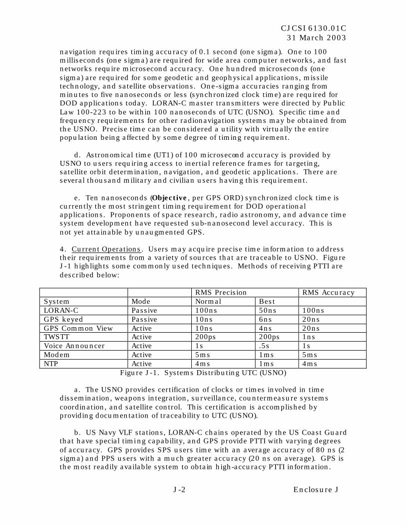
CJCSI 6130.01C 31 March 2003
J-2 Enclosure J
navigation requires timing accuracy of 0.1 second (one sigma). One to 100 milliseconds (one sigma) are required for wide area computer networks, and fast networks require microsecond accuracy. One hundred microseconds (one sigma) are required for some geodetic and geophysical applications, missile technology, and satellite observations. One-sigma accuracies ranging from minutes to five nanoseconds or less (synchronized clock time) are required for DOD applications today. LORAN-C master transmitters were directed by Public Law 100-223 to be within 100 nanoseconds of UTC (USNO). Specific time and frequency requirements for other radionavigation systems may be obtained from the USNO. Precise time can be considered a utility with virtually the entire population being affected by some degree of timing requirement.
d. Astronomical time (UT1) of 100 microsecond accuracy is provided by
USNO to users requiring access to inertial reference frames for targeting, satellite orbit determination, navigation, and geodetic applications. There are several thousand military and civilian users having this requirement.
e. Ten nanoseconds (Objective, per GPS ORD) synchronized clock time is
currently the most stringent timing requirement for DOD operational applications. Proponents of space research, radio astronomy, and advance time system development have requested sub-nanosecond level accuracy. This is not yet attainable by unaugmented GPS.
4. Current Operations. Users may acquire precise time information to address their requirements from a variety of sources that are traceable to USNO. Figure J-1 highlights some commonly used techniques. Methods of receiving PTTI are described below:
RMS Precision RMS Accuracy System Mode Normal Best LORAN-C Passive 100ns 50ns 100ns GPS keyed Passive 10ns 6ns 20ns GPS Common View Active 10ns 4ns 20ns TWSTT Active 200ps 200ps 1ns Voice Announcer Active 1s .5s 1s Modem Active 5ms 1ms 5ms NTP Active 4ms 1ms 4ms
Figure J-1. Systems Distributing UTC (USNO)
a. The USNO provides certification of clocks or times involved in time dissemination, weapons integration, surveillance, countermeasure systems coordination, and satellite control. This certification is accomplished by providing documentation of traceability to UTC (USNO).
b. US Navy VLF stations, LORAN-C chains operated by the US Coast Guard
that have special timing capability, and GPS provide PTTI with varying degrees of accuracy. GPS provides SPS users time with an average accuracy of 80 ns (2 sigma) and PPS users with a much greater accuracy (20 ns on average). GPS is the most readily available system to obtain high-accuracy PTTI information.
CJCSI 6130.01C 31 March 2003
J-3 Enclosure J
c. All National Institute of Standards and Technology (NIST) time signal
transmissions and some selected foreign transmissions are being monitored in order to make precision corrections available to users and to radio distribution services. This monitoring procedure permits the reference of time signals to any of the major time scales in use including Astronomical Time, UTC, and GPS time.
d. Radio broadcast of time signals (coded or plain language time
information) is available from the NIST stations WWV, WWVH, and WWVB, a system funded by the Department of Commerce. Time signals are synchronized with the USNO Master Clock to within 1 microsecond. The accuracy of signals received beyond line of sight from the stations (with nominal correction for the ionosphere and propagated signal path) is on the order of 1 millisecond.
e. TWSTT is available from USNO for high-precision PTTI. This procedure
makes use of geostationary communications satellites to transfer time. The level of accuracy depends on the user’s situation. If the user’s geodetic position is known to within a few hundred miles and the TWSTT system is calibrated, one nanosecond time transfer is possible. Accuracy is degraded when the user’s position is poorly determined or the receiving system is un-calibrated.
f. DSCS stations maintain precise time traceable to the USNO Master Clock,
and the system serves as a trunk line to provide precise time to certain other facilities. Time comparisons made through the system are operationally accurate to 0.1 microsecond and have the capability of providing time accuracy of 10 to 50 nanoseconds. The USNO provides a voice time announcement and time ticks (accurate to the millisecond level if propagation delays are known from a previous measurement). See Figures J-2 and J-3.
h. The USNO provides computer network time synchronization service
meeting Internet standard RFC-1305 NTP. USNO NTP servers provide UTC (USNO) with millisecond accuracy over wide area networks, including the Non-Secure Internet Protocol Routing Network (NIPRNET) and SIPRNET. Servers are geographically dispersed to minimize network delay and distribute traffic.
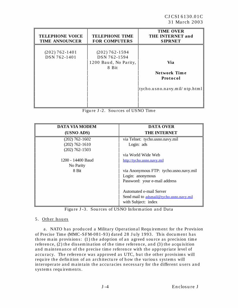
CJCSI 6130.01C 31 March 2003
J-4 Enclosure J
TELEPHONE VOICE TIME ANNOUNCER
TELEPHONE TIME FOR COMPUTERS
TIME OVER THE INTERNET and
SIPRNET
(202) 762-1401 DSN 762-1401
(202) 762-1594 DSN 762-1594
1200 Baud, No Parity, 8 Bit
Via
Network Time Protocol tycho.usno.navy.mil/ntp.html
Figure J-2. Sources of USNO Time
DATA VIA MODEM (USNO ADS)
DATA OVER THE INTERNET
(202) 762-1602 via Telnet: tycho.usno.navy.mil (202) 762-1610 Login: ads (202) 762-1503
via World Wide Web 1200 - 14400 Baud http://tycho.usno.navy.mil
No Parity 8 Bit via Anonymous FTP: tycho.usno.navy.mil
Login: anonymous Password: your e-mail address Automated e-mail Server Send mail to [email protected] with Subject: index
Figure J-3. Sources of USNO Information and Data 5. Other Issues
a. NATO has produced a Military Operational Requirement for the Provision of Precise Time (MMC-SFM-081-93) dated 28 July 1993. This document has three main provisions: (1) the adoption of an agreed source as precision time reference, (2) the dissemination of the time reference, and (3) the acquisition and maintenance of the precise time reference with the appropriate level of accuracy. The reference was approved as UTC, but the other provisions will require the definition of an architecture of how the various systems will interoperate and maintain the accuracies necessary for the different users and systems requirements.
CJCSI 6130.01C 31 March 2003
J-5 Enclosure J
b. GPS is the primary source of PTTI for operational forces. The interface between USNO and GPS is specified by the interface control document ICD-GPS-202 that states that GPS time must be maintained within one microsecond of UTC (USNO). There is a further requirement that the transmitted correction to UTC must be within 28 ns (1 sigma). Historical data has shown that GPS time has been within 100 ns of UTC (USNO), and the correction to UTC (USNO) has been well within 20 ns. Because the epoch of GPS time differs from UTC, there are an integral number of seconds between the two.
c. The Navy continues to upgrade the Master Clock System at the USNO to achieve an order of magnitude improvement to one part in 10 to the 15th. This time reference system will be used for both current and projected user systems with PTTI requirements that exceed current capabilities, e.g., GPS.
6. Precise Time Stations. A plan for a Distributed Master Clock is being developed in the event that the USNO may become incapacitated and to meet future requirements not anticipated to be met by GPS. The Distributed Master Clock will consist of Precise Time Stations, having a reference clock traceable to UTC (USNO). The nucleus of this Distributed Master Clock is the USNO AMC station located at Schriever AFB, Colorado. The UTC (USNO) dissemination functions will be transferred automatically from Washington, D.C., to Colorado as required.

CJCSI 6130.01C 31 March 2003
J-6 Enclosure J
(INTENTIONALLY BLANK)
CJCSI 6130.01C 31 March 2003
K-1 Enclosure K
ENCLOSURE K
REFERENCES
a. CJCSI 3170.01B, 15 April 2001, “Requirements Generation System” b. DOD Directive 4650.5, 5 December 1990, “Positioning and Navigation Systems Administration and Planning” c. DOT-VNTSC-RSPA-01-3 DOD-4650.5, “2001 Federal Radionavigation Plan” d. DOT-VNTSC-RSPA-01-3.1 DOD-4650.5, “2001 Federal Radionavigation Systems” e. “Global Positioning System Standard Positioning Service Performance Standard,” 4 October 2001 f. “Department of Defense Global Positioning System (GPS) Security Policy,” 29 March 1999, Reprint February 28, 2002 g. US Global Positioning System Policy, Presidential Decision Directive, (PDD) NSTC-6, 28 March 1996 h. CJCSI 6140.01, 15 November 1998, “NAVSTAR Global Positioning System Selective Availability Anti-Spoofing Module Requirements” i. CJCSI 3010.02A, 15 April 2001, “Joint Vision Implementation Master Plan’” j. Deputy Secretary of Defense memo, 8 September 1998, “Positioning, Navigation, and Timing” k. Operational Requirements Document (ORD) AFSPC/ACC 003-92-I/II/III Global Positioning System (GPS), 18 February 2000

CJCSI 6130.01C 31 March 2003
K-2 Enclosure K
(INTENTIONALLY BLANK)
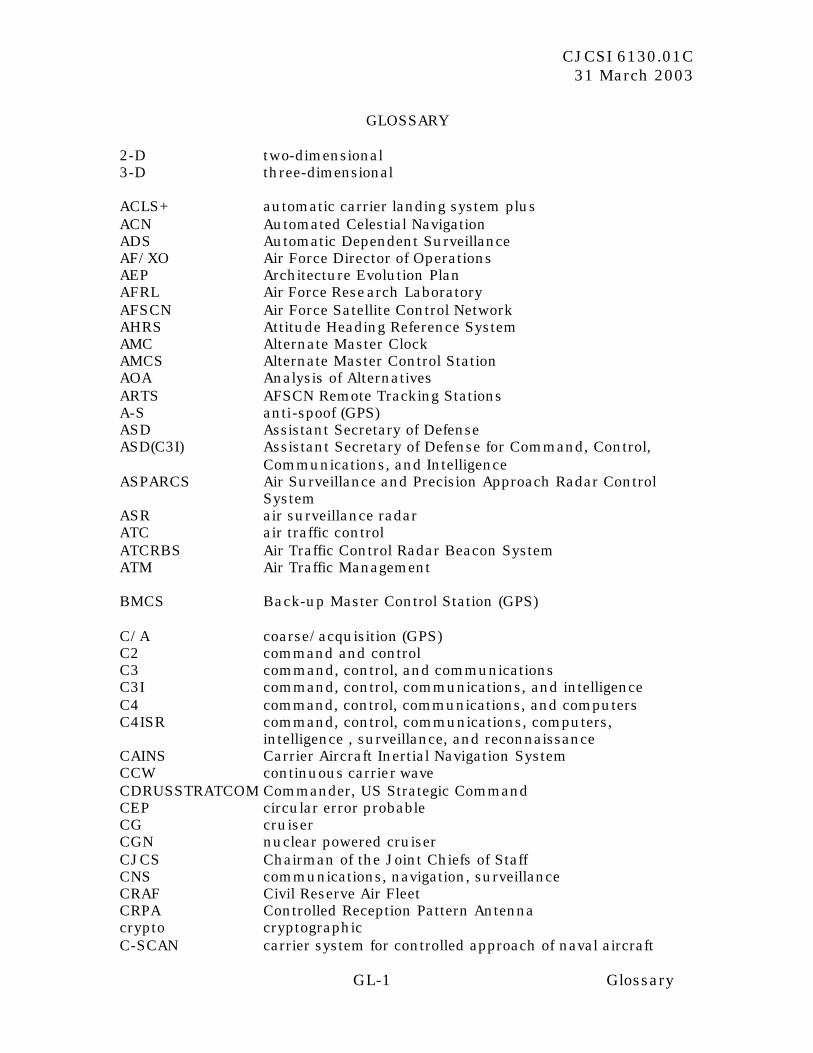
CJCSI 6130.01C 31 March 2003
GL-1 Glossary
GLOSSARY
2-D two-dimensional 3-D three-dimensional ACLS+ automatic carrier landing system plus ACN Automated Celestial Navigation ADS Automatic Dependent Surveillance AF/XO Air Force Director of Operations AEP Architecture Evolution Plan AFRL Air Force Research Laboratory AFSCN Air Force Satellite Control Network AHRS Attitude Heading Reference System AMC Alternate Master Clock AMCS Alternate Master Control Station AOA Analysis of Alternatives ARTS AFSCN Remote Tracking Stations A-S anti-spoof (GPS) ASD Assistant Secretary of Defense ASD(C3I) Assistant Secretary of Defense for Command, Control,
Communications, and Intelligence ASPARCS Air Surveillance and Precision Approach Radar Control
System ASR air surveillance radar ATC air traffic control ATCRBS Air Traffic Control Radar Beacon System ATM Air Traffic Management BMCS Back-up Master Control Station (GPS) C/A coarse/acquisition (GPS) C2 command and control C3 command, control, and communications C3I command, control, communications, and intelligence C4 command, control, communications, and computers C4ISR command, control, communications, computers,
intelligence , surveillance, and reconnaissance CAINS Carrier Aircraft Inertial Navigation System CCW continuous carrier wave CDRUSSTRATCOM Commander, US Strategic Command CEP circular error probable CG cruiser CGN nuclear powered cruiser CJCS Chairman of the Joint Chiefs of Staff CNS communications, navigation, surveillance CRAF Civil Reserve Air Fleet CRPA Controlled Reception Pattern Antenna crypto cryptographic C-SCAN carrier system for controlled approach of naval aircraft
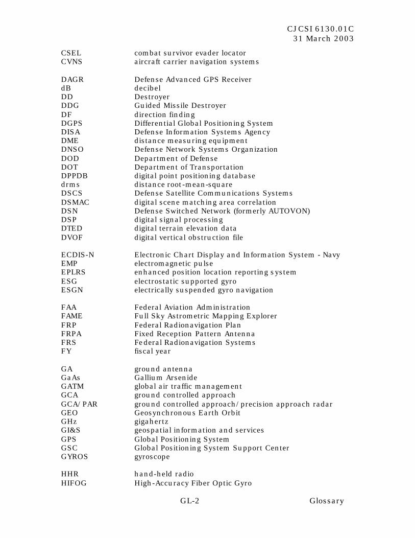
CJCSI 6130.01C 31 March 2003
GL-2 Glossary
CSEL combat survivor evader locator CVNS aircraft carrier navigation systems DAGR Defense Advanced GPS Receiver dB decibel DD Destroyer DDG Guided Missile Destroyer DF direction finding DGPS Differential Global Positioning System DISA Defense Information Systems Agency DME distance measuring equipment DNSO Defense Network Systems Organization DOD Department of Defense DOT Department of Transportation DPPDB digital point positioning database drms distance root-mean-square DSCS Defense Satellite Communications Systems DSMAC digital scene matching area correlation DSN Defense Switched Network (formerly AUTOVON) DSP digital signal processing DTED digital terrain elevation data DVOF digital vertical obstruction file ECDIS-N Electronic Chart Display and Information System - Navy EMP electromagnetic pulse EPLRS enhanced position location reporting system ESG electrostatic supported gyro ESGN electrically suspended gyro navigation FAA Federal Aviation Administration FAME Full Sky Astrometric Mapping Explorer FRP Federal Radionavigation Plan FRPA Fixed Reception Pattern Antenna FRS Federal Radionavigation Systems FY fiscal year GA ground antenna GaAs Gallium Arsenide GATM global air traffic management GCA ground controlled approach GCA/PAR ground controlled approach/precision approach radar GEO Geosynchronous Earth Orbit GHz gigahertz GI&S geospatial information and services GPS Global Positioning System GSC Global Positioning System Support Center GYROS gyroscope HHR hand-held radio HIFOG High-Accuracy Fiber Optic Gyro
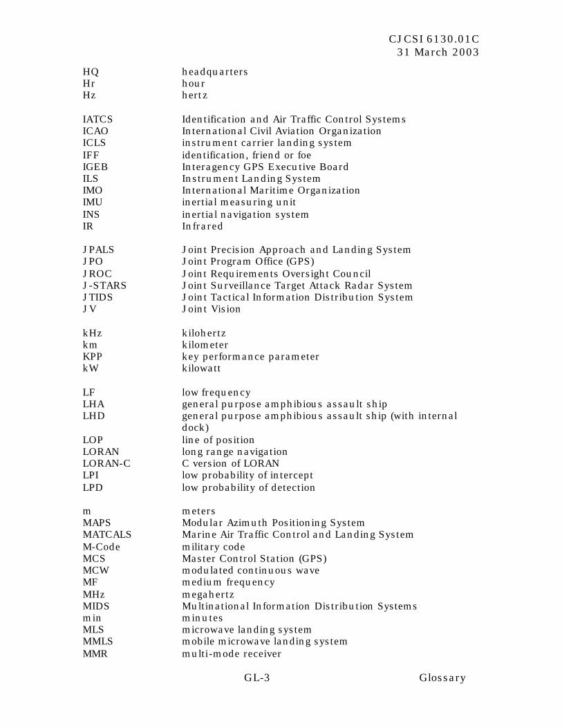
CJCSI 6130.01C 31 March 2003
GL-3 Glossary
HQ headquarters Hr hour Hz hertz IATCS Identification and Air Traffic Control Systems ICAO International Civil Aviation Organization ICLS instrument carrier landing system IFF identification, friend or foe IGEB Interagency GPS Executive Board ILS Instrument Landing System IMO International Maritime Organization IMU inertial measuring unit INS inertial navigation system IR Infrared JPALS Joint Precision Approach and Landing System JPO Joint Program Office (GPS) JROC Joint Requirements Oversight Council J-STARS Joint Surveillance Target Attack Radar System JTIDS Joint Tactical Information Distribution System JV Joint Vision kHz kilohertz km kilometer KPP key performance parameter kW kilowatt LF low frequency LHA general purpose amphibious assault ship LHD general purpose amphibious assault ship (with internal
dock) LOP line of position LORAN long range navigation LORAN-C C version of LORAN LPI low probability of intercept LPD low probability of detection m meters MAPS Modular Azimuth Positioning System MATCALS Marine Air Traffic Control and Landing System M-Code military code MCS Master Control Station (GPS) MCW modulated continuous wave MF medium frequency MHz megahertz MIDS Multinational Information Distribution Systems min minutes MLS microwave landing system MMLS mobile microwave landing system MMR multi-mode receiver
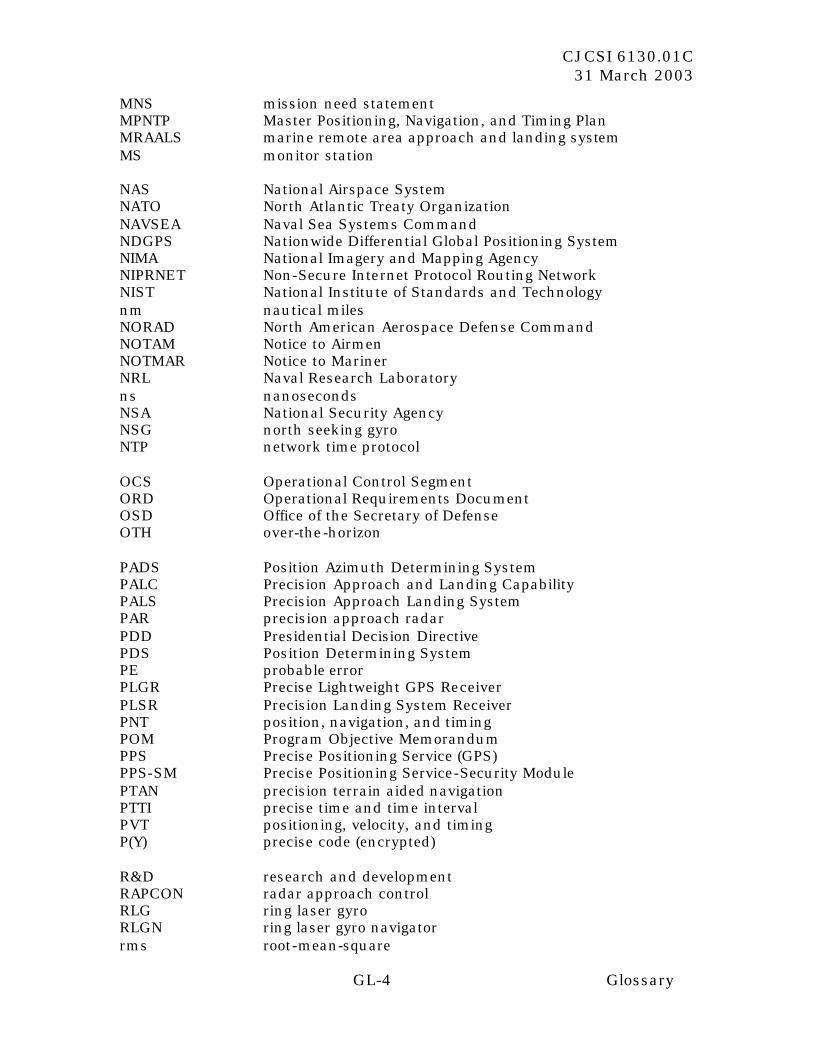
CJCSI 6130.01C 31 March 2003
GL-4 Glossary
MNS mission need statement MPNTP Master Positioning, Navigation, and Timing Plan MRAALS marine remote area approach and landing system MS monitor station NAS National Airspace System NATO North Atlantic Treaty Organization NAVSEA Naval Sea Systems Command NDGPS Nationwide Differential Global Positioning System NIMA National Imagery and Mapping Agency NIPRNET Non-Secure Internet Protocol Routing Network NIST National Institute of Standards and Technology nm nautical miles NORAD North American Aerospace Defense Command NOTAM Notice to Airmen NOTMAR Notice to Mariner NRL Naval Research Laboratory ns nanoseconds NSA National Security Agency NSG north seeking gyro NTP network time protocol OCS Operational Control Segment ORD Operational Requirements Document OSD Office of the Secretary of Defense OTH over-the-horizon PADS Position Azimuth Determining System PALC Precision Approach and Landing Capability PALS Precision Approach Landing System PAR precision approach radar PDD Presidential Decision Directive PDS Position Determining System PE probable error PLGR Precise Lightweight GPS Receiver PLSR Precision Landing System Receiver PNT position, navigation, and timing POM Program Objective Memorandum PPS Precise Positioning Service (GPS) PPS-SM Precise Positioning Service-Security Module PTAN precision terrain aided navigation PTTI precise time and time interval PVT positioning, velocity, and timing P(Y) precise code (encrypted) R&D research and development RAPCON radar approach control RLG ring laser gyro RLGN ring laser gyro navigator rms root-mean-square
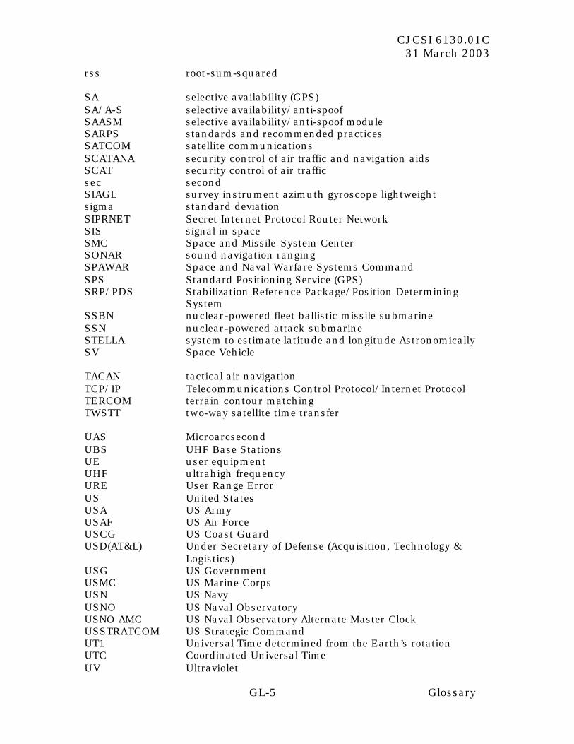
CJCSI 6130.01C 31 March 2003
GL-5 Glossary
rss root-sum-squared SA selective availability (GPS) SA/A-S selective availability/anti-spoof SAASM selective availability/anti-spoof module SARPS standards and recommended practices SATCOM satellite communications SCATANA security control of air traffic and navigation aids SCAT security control of air traffic sec second SIAGL survey instrument azimuth gyroscope lightweight sigma standard deviation SIPRNET Secret Internet Protocol Router Network SIS signal in space SMC Space and Missile System Center SONAR sound navigation ranging SPAWAR Space and Naval Warfare Systems Command SPS Standard Positioning Service (GPS) SRP/PDS Stabilization Reference Package/Position Determining
System SSBN nuclear-powered fleet ballistic missile submarine SSN nuclear-powered attack submarine STELLA system to estimate latitude and longitude Astronomically SV Space Vehicle TACAN tactical air navigation TCP/IP Telecommunications Control Protocol/Internet Protocol TERCOM terrain contour matching TWSTT two-way satellite time transfer UAS Microarcsecond UBS UHF Base Stations UE user equipment UHF ultrahigh frequency URE User Range Error US United States USA US Army USAF US Air Force USCG US Coast Guard USD(AT&L) Under Secretary of Defense (Acquisition, Technology &
Logistics) USG US Government USMC US Marine Corps USN US Navy USNO US Naval Observatory USNO AMC US Naval Observatory Alternate Master Clock USSTRATCOM US Strategic Command UT1 Universal Time determined from the Earth’s rotation UTC Coordinated Universal Time UV Ultraviolet
CJCSI 6130.01C 31 March 2003
GL-6 Glossary
VHF very high frequency VLF very low frequency VOR very high frequency omni-directional range station VORTAC combined very high frequency omni-directional
range/tactical air navigation station WAAS Wide Area Augmentation System (GPS) WGS 84 World Geodetic System 1984 WRC World Radio (communication) Conference WWV call letters for radio stations broadcasting time signals WWVB call letters for radio stations broadcasting time signals WWVH call letters for radio stations broadcasting time signals Y code precise code (GPS)


![FEB 0 6 2007dcfpnavymil.org/Personnel Protection/tip01/5100.24B[1].pdfCapabilities Guidebook, of Feb 05 Chairman, Joint Chiefs of Staff Instruction (CJCSI) 3170.01E1 Joint Capabilities](https://img.pdfslide.net/doc/110x75/5fec7c76860711202a2adb29/feb-0-6-protectiontip01510024b1pdf-capabilities-guidebook-of-feb-05-chairman.jpg)