Embed Size (px)
Citation preview

HAL Id: hal-02301564https://hal-mines-albi.archives-ouvertes.fr/hal-02301564
Submitted on 4 Oct 2019
HAL is a multi-disciplinary open accessarchive for the deposit and dissemination of sci-entific research documents, whether they are pub-lished or not. The documents may come fromteaching and research institutions in France orabroad, or from public or private research centers.
L’archive ouverte pluridisciplinaire HAL, estdestinée au dépôt et à la diffusion de documentsscientifiques de niveau recherche, publiés ou non,émanant des établissements d’enseignement et derecherche français ou étrangers, des laboratoirespublics ou privés.
Scale-up in Turbula (R) mixers based on the principle ofsimilarities
Claire Mayer-Laigle, Cendrine Gatumel, Henri Berthiaux
To cite this version:Claire Mayer-Laigle, Cendrine Gatumel, Henri Berthiaux. Scale-up in Turbula (R) mixers based onthe principle of similarities. Particulate Science and Technology, Taylor & Francis, 2020, 38 (8),pp.973-984. �10.1080/02726351.2019.1644689�. �hal-02301564�

Scale-up in TurbulaVR mixers based on the principle of similarities
Claire Mayer-Laiglea, Cendrine Gatumelb, and Henri Berthiauxb
aIATE, Univ Montpellier, CIRAD, INRA, Montpellier SupAgro, Montpellier, France; bUniversit�e de Toulouse, IMT Mines Albi, UMR CNRS 5302,RAPSODEE, Campus Jarlard, Albi, France
ABSTRACTMany processes from a wide range of industries use powders as raw materials. In most of them,mixing of dry particles is a critical step. However, the complexity of granular materials leads to dif-ficulties in predicting behavior of powders inside a blender. Cost and amount of raw materialsneeded to achieve these studies imply that such work is often performed at the laboratory scale.The main challenge then lies in the extrapolation of results from lab to pilot or industrial scalewith minimum testing in order to optimize costs. Defining reliable scale-up laws for powdermixers remains one of the main industrial issues. The work presented here concerns the scaling-up of TurbulaVR mixers that are commonly used both in industry and research. Mixtures obtainedin different mixer sizes have been compared on the basis of kinematic and dynamic similaritiesand discussed according to the different flow regimes involved. The dynamic similarities appear tolead to mixture qualities at different scales closer to each other than those obtained on the basisof kinematic similarities probably because of similar flow regimes. However, some other parame-ters must be taken into consideration, such as the free surface of powder related to the fillingratio.
GRAPHICAL ABSTRACT
Variation coefficients obtained for the operating points KOP1, KOP2, DOP1 and DOP2 at 6 (a) and12 (b) revolutions for a cohesive blend.
HIGHLIGHTS
� We define scale-up laws for powder TurbulaVR blenders from lab to industrial scale.� Kinematic and dynamic similarities were studied for three sizes of mixer.� Dynamic similarities lead to similar mixture qualities at different scales.� Kinematic and dynamic similarities are discussed according to powder flow regimes.
KEYWORDSTurbulaVR blender; powdermixing; scale-up; kinematicand dynamic similarities
1. Introduction
Granular materials are present in numerous processes, in allindustrial sectors. In many of them, mixing or premixing ofdry particles is a critical step since it controls the propertiesof the finished product (color, taste, bioavailability of adrug) (Shenoy et al. 2015). It can influence the downstreamsteps (Zhou and Morton 2012), as for example, in dry lubri-cation processes (Suzuki et al. 2015). At the process scale,
granular materials can be seen as a state of matter at thecrossroad between the solid and the liquid states (Redaelliet al. 2017). Granular materials appear as a multitude ofgrains, behaving as a solid in isolated form and exhibitinginternal discontinuities, according to the size, the shape,and the nature of the interactions (Shah et al. 2017). Thesediscontinuities induce a partial transmission of the stressesduring the process, making the behavior of the raw material
CONTACT Cendrine Gatumel [email protected] Universit�e de Toulouse, IMT Mines Albi, UMR CNRS 5302, RAPSODEE, Campus Jarlard,F-81013, Albi, France.

difficult to describe, flowing sometimes as a liquid or aggre-gating under the form of clusters (Savage 1984).
These complex systems cannot be easily describedthrough a limited number of physical parameters(Ammarcha et al. 2013). Simulation could be used to under-stand mixing mechanisms inside the blender in order toimprove design or operations (Yamamoto, Ishihara, andKano 2016) (Qi, Heindel, and Wright 2017) (Xiao et al.2017), but this data is difficult to transpose to a real mater-ial, for which shapes and sizes of particles are widely dis-persed. Therefore, the optimization of mixing or aformulation step cannot be performed without experimentalwork that is usually tedious. The cost and the quantity ofraw materials needed to achieve these studies imply thatsuch work is often performed at the laboratory scale. Themain challenge lies then in the extrapolation of results fromlab to pilot or industrial scale through a small number oftests. The invariant involved in scale-up strategies of themixer is generally a quality index but some other values aresometimes considered, such as for example, a velocity of dis-placement of particles in the case of fragile or friable prod-ucts (Suzuki et al. 2015). The extrapolation work is neversimple since the methods typically used in chemical engin-eering are not really adapted to granular materials(Bridgwater 2012). The scale-up of powder mixers is stillpoorly studied in the scientific literature, most of the workhas focused on the understanding of mixing mechanisms,which is often a prerequisite to the scale-up.
Nevertheless, over the last 5 years, several publicationsexplored scale effects of granular mixing (Marmur andHeindel 2017) and the scale-up of some common dry pow-der mixers based on different strategies: a detailed descrip-tion of the mixing operation based on mathematicalequations for rotary drums (Ding et al. 2001), the principleof similarities for rotating drum (Alexander, Shinbrot, andMuzzio 2002), the use of numerical simulation for continu-ous rotary blade mixers (Yijie, Muzzio, and Ierapetritou2013), the use of some dimensionless numbers such as theFroude number for a high shear mixer (Cavinato et al.2013), the construction of an empirical model for V-blen-ders (Suzuki et al. 2015) and the Power Number for a rotor-stator mixer (James et al. 2017).
The difficulty to obtain homogeneous powder mixturesguaranteeing the quality criteria has led to the developmentof a wide range of mixers using inertia or G-force to over-come the particular interactions and favor the intimate mix-ing of all constituents. To prevent segregation phenomena,mixers generating a non-regular motion are often preferred.However, in this case, scale-up rules are even more difficultto define, as the motion of particles is complex. TheTurbulaVR mixer is commonly used for the homogenizationof many powder systems in both industry and research(Kushner 2012). Its efficiency is mainly based on the com-bination of three motions, namely, a revolution, a transla-tion, and an inversion (Wohlhart 1981). This results in athree-dimensional and nearly chaotic motion that helps inobtaining a homogeneous mixture rapidly for many granularsystems. The motion of the mixer and mixing dynamics for
an easy flowing powder blend has been described in a previ-ous paper (Mayer-Laigle, Gatumel, and Berthiaux 2015).Cascading regime has been found to be the best one forhomogenization. In the present work, we explore the poten-tial of geometric, kinematic, and dynamic criteria, as well asflowing regimes to define scale-up rules for TurbulaVR mixerswith the aim of reaching the same mixture quality for botheasy-flowing and cohesive powder blends.
2. Materials and experimental procedures
2.1. The TurbulaVR mixer
In the TurbulaVR mixer, the powders to mix are poured intoa closed container which is inserted in a mixing basket setby 2 stirrups at 2 rotary axes (see Figure 1). One of themdrives the whole system by rotating at a fixed speed, hence-forth called engine speed, which can be adjusted. The move-ment of the system is possible if and only if the radius ofthe stirrup is equal to the center distance between the twostirrups (Wohlhart 1981). The mixing basket can hold anyform of container, henceforth called vessel, fixed thanks toelastic bands.
The three TurbulaVR scales available on the market wereinvestigated in this work, namely, laboratory Scale –TurbulaVR T 2 F (2 l), pilot scale – TurbulaVR T 10B (17 l),industrial scale – TurbulaVR T 50A (50 l). The latter corre-sponds to the maximum size of the standard vessel providedfor the equipment. The motion of the vessel is driven by thespeed of the rotary axis. Four or five speeds are availableaccording to the different device’s scale and are summarisedin Figure 1.
2.2. Raw powders flow properties and composition ofthe different blends
The behavior of powders inside the vessel depends both onprocess parameters and flow properties of powders. To givea more complete view of scaling parameters inside themixer, two powder blends of different flow properties havebeen studied. Each blend is composed of two constituents inrelative proportion by weight 85:15. The first blend, quali-fied as a free flowing blend (FFB), is made of lactoseGRANULAC 140 (85% w/w) marketed by the companyMEGGLE and commercial couscous of durum semolina(15% w/w). Couscous particles have been dyed black by iod-ine adsorption to increase the color contrast between thetwo constituents for further image analysis (proceduredetailed later). The second blend, called composite cohesiveblend (CCB), is made up of 85% graphite (Timrex KS 150
Center distance
Radius of stirrup
Engine speed of rotary axis - T 2F (22, 32, 48, 64, 96 rpm) - T10B ( 15, 23, 32, 44 rpm) - T50A (16, 20 25, 32, 40 rpm)
Point at the bottom of the vessel (A)
Figure 1. Schematic representation of a Turbula mixer.

by society TIMCAL) and 15% thermossetting polymericmatrix (with 97% epoxy resin DGEBA produced by thecompany RAIGI). This blend, as opposed to the first one,has an industrial purpose as it is intended for the manufac-turing of bipolar plates for fuel cells. The volumetric medianparticle size and the dispersion index, DI ¼ ðd90�d10Þ
d50; which
characterizes the particle size span, have been determinedfor each powder by LASER diffraction using a MalvernMetasizer Scirocco 2000 (Malvern Instruments Ltd., UnitedKingdom) and are reported in Table 1. In the case of thecomposite cohesive blend, the properties of the termosset-ting polymeric matrix have been approximated by those ofthe epoxy resin.
To estimate the flowability of each powder, Carr indexand Hausner ratio have been determined from the bulk(qa) and bulk packed densities (qp; after 500 taps) meas-ured thanks to a volumenometer Erweka SVM 22, andaccording to Equations (1) and (2). From these values,appreciations of the compressibility and the flowability ofeach powder have been given according to Carr (Carr1970) and Hausner (Hausner 1967). These results aresummarized in Table 1.
ICarr ¼qp�qaqp
(1)
RH ¼ qpqa
(2)
Couscous exhibits a very small Carr Index and Hausnerratio and can be considered as a free-flowing powder. Incontrast, Lactose shows very bad flowability. The flowabilityof the FFB is expected to be intermediate between that ofeach powder (Demeyre 2007). Indeed, the blend Carr Indexis 24.47% demonstrating an easy flowing behavior. Thus, thestrong difference between the particle sizes of lactose andcouscous is expected to induce a segregation phenomenonduring the mixing. For the CCB, the flowability and themedian diameter of each powder are closer. The flowabilityof the mixture is expected to be similar to those of the pow-ders and could be qualified of cohesive with no trend tosegregation.
2.3. Powder blending protocol
The powders have been mixed in stainless steel vessels (2 Lfor T2F, 17 L for T 10B, and 55 L for the T 50A) with a vol-umic filling ratio of approximately 50%. The powders wereweighed directly in the mixing vessel to prevent possiblepowder losses during handling. The mass of each constituentfor all TurbulaVR scales is summarized in Table 2. Afterchoosing the engine speed, the mixing operation has beenstarted for a pre-defined number of revolutions.
2.4. Assessment of blend’s homogeneity
The quantitative characterization of mixture quality requiresthe prior set-up of a sampling procedure (number and sizeof samples, “how to withdraw them?”), as well as the use ofa reliable method of measurement of the sample’s compos-ition. The method of measurement has to be adapted to thenature of the powders as well as to the intended use of thefinal product. In this work, a method has been developedfor each blend.
Mixture homogeneity is commonly assessed by the coeffi-cient of variation of the key component’s compositions inthe samples (i.e. lactose in FFB and graphite in CCB). Asmall CV means that the sample compositions are close toeach other and reflects a high homogeneity of the mixture:
CV ¼ rl
(3)
with l¼ average composition in key component of the sam-ples analyzed and r¼ the standard deviation associated.
2.4.1. Sampling procedure and composition measurementfor the free flowing blend
After mixing, the FFB is discharged through a funnel onto aconveyor belt (Massol-Chaudeur, Berthiaux, and Dodds2002). An inclined piece of stiff cardboard allows the forma-tion of a thin powder layer of constant width and thickness(see Figure 2(a)). There is no high fall of powder in ourdevice, which is known to be one of the main causes of seg-regation. Vibrations do not occur over a long distance. Thecardboard piece displays the powder on the conveyor and
Table 1. Powder characteristics and composition of the different blends.
Free flowing blend Composite cohesive blend
Lactose Couscous Graphite Polymeric matrix
Relative proportion by weight 85% 15% 85% 15%D50 (mm) 59 979 57 121DI 1.95 0.72 2.66 3.40Icarr 38% 7.3% 25% 42%RH 1.61 1.08 1.34 1.73Flowability Very bad Very good Bad ExecrableCompressibility High Low Medium High
Table 2. Calculated mass of the components for the make-up of the different powder blends at the three scales.
TurbulaVR T2F TurbulaVR T10B TurbulaVR T50A
Volume of the container 2 L 17 L 55 LMass of the blend 420 g 3570 g 11550 gMass of major component (lactose or graphite) 357.0 g 3034.5 g 9817.5 gMass of minor component (polymeric matrix or couscous) 63 g 535.5 g 1732.5 g

may also induce local segregation, which is the same for allexperiments we compare.
The color difference between the lactose (white powder)and the couscous (colored in black by iodine adsorption)allows assessment of the powder homogeneity by an imageprocessing technique according to the protocol developed byMayer-Laigle, Gatumel, and Berthiaux (2015). The measure-ment chain consists of a linear CCD camera placed over theconveyor belt and a computer. A time sequence of images iscaptured and treated with a program developed on theLabview software to determine its composition. Each imageacquired corresponds to an independent sample of approxi-mately 0.6 g. Blend homogeneity is assumed to be evenwhen observed on the surface and inside the volume of thepowder layer. By this way, the whole blend is fictitiouslysplit into samples and analyzed, therefore, homogeneity canbe obtained without any statistical assessment.
2.4.2. Sampling procedure and composition measurementmethod of the composite cohesive blends
The powder is discharged via a vibratory feeder onto a con-veyor belt whose speed is adjustable. In accordance with theindustrial final use for this blend (bipolar plate for fuel cell),the scale of scrutiny was evaluated to 70mg. No onlinemeasurement was easily implementable and an exhaustivesampling procedure was not an option as the number ofpotential samples is 6000, 51,000, and 165,000 for the T2F,T10B, and T50A, respectively. Eighty samples are withdrawnrandomly, thanks to racks laid on the conveyor belt (seeFigure 2). The mass of the sample has been set to 70mg byadjusting the speed of the conveyor and the amplitude ofvibration. The determination of the composition of eachsample is based on the combustion of the thermosettingpolymer in an oven at 550 �C for 2 hours. TGA confirmedthat the polymer is completely burned without any residualash. A weight loss of 0.4% was also observed for the graph-ite because of some moisture adsorbed on the surface ofgraphite particles. Composition of graphite inside the sampleis determined as the ratio between the corrected mass ofgraphite (to account for the weight loss of 0.4%) and thesample mass. To represent standard deviation results on dia-grams, a 90% range of confidence will be drawn according
to a v2 law. Mixture homogeneities are compared accordingto this statistical analysis.
3. Principe of similarities in the TurbulaVR mixer
In basic chemical engineering, two systems at different scalesare considered as completely similar if they take place in asimilar geometrical space and if all the dimensionless num-bers used to characterize the process are equal (Langhaar1980). In practice, it is impossible to reach a complete simi-larity, especially with granular materials for which a classicaldimensional analysis is arduous to conduct (Ding et al.2001). In the following, the principle of similarity is appliedin a simplified way based on both geometric and kinematicor dynamic similarities. Results obtained with kinematicbased similarity and dynamic based similarity will be dis-cussed in order to determine which phenomenon is prepon-derant to obtain homogeneous mixtures (flowing velocity,centrifugal force, etc).
3.1. Geometrical similarities
Two systems are geometrically similar if they exhibit a con-stant ratio between all their dimensions. In practice, even ifsuppliers try to abide by the geometric similarities, there arealways some distortions (Cavinato et al. 2013) due to themechanical environment (constraint) or simply due to theroughness of the surface that cannot be extrapolated(Midoux 1985).
In the TurbulaVR mixer, the dimensions that influence themotion of the powder are the diameter and length of thevessel, as well as the radius of the stirrup. These characteris-tic dimensions are summarized in Table 3 for the threescales. The ratios of the characteristic lengths of T10B andT50A on those of T2F were calculated. They are almostidentical for all characteristic lengths (�1.8 for T10B and�2.8 for T50A). A slight distortion on the diameter of thevessel does exist for the pilot scale mixer (T10B), but weassume that globally, the different scales appear to complywith geometric similarities.
Linear CCD camera
Wooden box to limitlight fluctua�ons
Powder layer ofconstant width andthickness
Inclined piece of s�ffcardboard
Funnel
Convey or belt
Rack
Funnel
Vibratory feed
Mixture to be analysed
(a) (b)
Figure 2. Device for analyzing the composition of the free flowing blend (a) and sampling procedure for the composite cohesive blend (b).

3.2. Kinematic and dynamic similarities
Kinematic similarities between the two scales imply that twocorresponding points will undergo a similar trajectorywithin a similar time. In the case of a liquid, this means thatthe fluid streamlines are the same. For a powder, streamlinesare not clearly defined and the motion of particles inside amixer is difficult to predict. Dynamic similarities refer to asame ratio between forces acting on corresponding points ineach system. In general, for powder mixing, authors assumethat kinematic similarities are satisfied if particles have thesame velocity at each mixer scale (Alexander, Shinbrot, andMuzzio 2002), (Nakamura et al. 2009). Concerning dynamicsimilarities, they are respected when the ratio of forces act-ing on corresponding points in each system is kept equal. Incase of powder, the mixture is achieved most of the time,thanks to the combination of inertial and G-force and theholding of dynamic similarities is often translated to a con-stant Froude number between the scales. However, if the useof the Froude number is widespread to extrapolate blenders,it has not been proven that it is the only criteria to be takeninto account (Landin et al. 1996), (Ding et al. 2001), (Clearyand Sinnott 2008). For example, energetic or kinetic criteriamay also be considered
The motion of the TurbulaVR mixer is complex, nearlychaotic. The particles inside the vessel are submitted toforces and velocities of widely variable directions and ampli-tudes, according to their positions in the powder bed and tothe process parameters (input speed of the rotary axis, sizeof the mixer, … ). In a previous work (Mayer-Laigle,Gatumel, and Berthiaux 2015), the three mixers have beenmodeled with SolidworksVR software in order to thoroughlystudy the motion of the vessel. In particular, we show that itcan be decomposed in displacement, rotation, and reversalphase. We also show that a point at the bottom of the vessel(Point A, in Figure 1) could be used to broadly describe themotion of the powder bed. This point corresponds to thebottom of the powder bed in the initial configuration.During the rotation, the powder is “reversed” and then thevelocity and the acceleration at point A can be seen as theinitial falling conditions of the particles from the top to thebottom of the vessel. Indeed, mixing is supposed to happenin flows during falling situations, as in a rotating drum. Weassume that all the particles in the powder bed will be nearthis point at a given time and will be submitted to similarforces and velocities.
During a period of rotation, the kinetic profile of thepoint A shows a maximum which corresponds to displace-ment phases of the vessel and we define kinematic criteriabased on the maximum velocity at this point. (see Figure 3).
For dynamic similarities, the main forces that act on thepowder during the mixing process are, respectively, the G-force and the centrifugal force. The Froude number, whichis defined as the ratio of the inertial force on gravity, at thereference point has been chosen as the dynamic criteria(Equation 4).
Fr ¼ Inertial ForceGravity force
¼ ag
(4)
In the above, g is the acceleration due to gravity(9.81 m.s�2) and a is the acceleration for the reference pointA at the bottom of the vessel. As can be seen on Figure 3,the acceleration profile of this point also shows a maximumcorresponding to reversal phases of the vessel. MaximalFroude numbers for the reference point have been extractedfrom the simulations and have been chosen as adynamic criterion.
The evolution of the maximal velocity and the Froudenumber as a function of the engine speed are shown inFigures 3(a,b), respectively for the different scales. The dotscorrespond to the SolidworksVR calculated values and linearregressions are featured on the graph.
For each scale, the maximum velocity is proportional tothe engine speed N. Similarily, Froude numbers are propor-tionnal to N2. One can note that the ratio between theslopes of linear regressions for the different Turbula scales issimilar to those between the characteristic lengths(see Table 3):
aT50AaT2F
� bT50AbT2F
� 2:8 andaT10BaT2F
� bT10BbT2F
� 1:8 (5)
with aT2F, aT10B, aT50A, and bT2F, bT10B, bT50A, the slopesobtained for the T2F, T10B, and T50A for the maximumvelocity and the Froude number, respectively.
Indeed, in the TurbulaVR mixer, the only parameters thatcould influence the velocities and accelerations are the char-acteristic lengths of the mixer and the engine speed. In thedifferent mixers, the velocity varies from 0.5 m.s�1 to almost2.5 m.s�1. The velocity obtained in the T50A for the inputspeed of 40 rpm cannot be reached in the T2F or the T10B.For example, a similar velocity (V¼ 0.4 m.s�1) at the bot-tom of the mixers is obtained when using an input speed ofeither 8 rpm in the T2F, about 12 rpm in the T10B, or22 rpm in the T50A. Similarly, the maximum Froude num-ber (Fr ¼ 4.5) can only be reached in the T2F for the inputspeed of 96 rpm and is more than twice the maximumFroude number obtained in T10B (Fr ¼ 1.7 for an inputspeed of 44 rpm) and T50A (Fr ¼ 2.2 for input speed of40 rpm). A similar Froude number of 0.5 can be obtained in
Table 3. Characteristic dimensions for the TurbulaVR T2F, T10B et T50A.
Laboratory scale: T2F Pilot scale: T10B Industrial scale: T50AdT10BdT2F
dT50AdT2F
Volume of the container 2 L 17 L 8.5 55 L 27.5Radius of the stirrup 130mm 225mm 1.73 360mm 2.77Diameter of the vessel 130mm 252mm 1.93 370mm 2.84Length of the vessel 200mm 360mm 1.8 565mm 2.83

the T2F, T10B, and T50A for input speeds of 32, 24, and20 rpm, respectively. However, for each mixer scale, thereare only 4 or 5 engine speeds available (actual engine speed)and it is not possible to obtain exactly the same velocity orFroude number in different scales. To overcome this andenable comparisons over the scales, Kinematic (KOP) andDynamic Operating Points (DOP) have been defined (Tables4 and 5) in such a way that the relative differences betweenthe equivalent engine speeds (determined from the linearregression on Figure 4) and the actual engine speed are aslow as possible and always less than 15%. For most kine-matic operating points, the comparison will only involvetwo sizes of mixers. Only the KOP2 and KOP3 allow a com-parison between the three scales.
The velocity and acceleration profiles in point A havebeen compared for the different operating points and Figure5 shows those obtained for the KOP2 (Figures 5(a,b)) andDOP3 (Figures 5(b,d)), respectively. The dimensionless time(s) was obtained by dividing the time by the motion period,i.e. the duration of one rotation of the engine axis. Good
adequacy of velocity profiles at the three blender sizes isobserved in case of kinematic similarities (Figure 5(a)) andthe same goes for accelerations in the case of dynamic simi-larities (Figure 5(d)). However, as can be seen in Figures4(a,b) for kinematic as well as 5c and 5d for dynamic simi-larities, both criteria cannot be met simultaneously.
3.3. Flow regimes in the different TurbulaVR scales
Several studies, in particular, on rotating drums, have shownthat the state of the mixture is mainly related to the flowregime that takes place inside the mixer (Henein,Brimacombe, and Watkinson 1983; Mellmann 2001; Yanget al. 2008), as defined on the basis of the Froude numberand the filling degree of the blender. According to the flowregimes, the mixing mechanisms may differ and drive to dif-ferent mixture patterns (Mayer-Laigle, Gatumel, andBerthiaux 2015). Drawing upon these studies, three flowingregimes in the three TurbulaVR scales for the different enginespeeds have been defined (see Table 6):
i. A cascading regime when Fr �0.5. In this case, G-forcemainly governs powder flow in the mixer and the flowregime is quite similar to the cascading regime in arotating drum.
ii. A cataracting regime for Froude numbers between 0.8and 2.5, where both gravity force and centrifugal forceare responsible for the state of the mixture.
iii. A collisional regime for which the centrifugal forcesare predominant and mixing is probably achieved,thanks to diffusion (Fr � 2.5). It can be noted that thecollisional mode is only possible in the T2F.
Experimental results obtained in the different scales cannow be compared on the basis of the different kinematicand dynamic operating points, keeping in mind the differentflow regimes inside the mixers.
0,2
0,3
0,4
0,5
0,6
0 1 2 3 4 5Time (s)
Vel
ocit
y(m
/s)
1
1,5
2,0
2,5
0 1 2 3 4 5Time (s)
Acc
eler
atio
n(m
/s²)
3,0
t= 0.34T t= 0.87Tt= 0.51T t=Tt =0.95Tt = 0.44T
Displacement phases Reversal phases
Figure 3. Kinetic and acceleration profiles over a period of time for point A in T2F–22 rpm. The position of the vessel extracted from the simulation have been dis-played in the figure. The white arrows indicate the direction of the motion.
Table 4. Kinematic operating points (KOP) for each scale of TurbulaVR mixers.
N in T2F N in T10B N in T50AMaximum velocity in
point A, m.s�1
KOP1 32 rpm 15 rpm �0.6KOP2 46 rpm 23 rpm 16 rpm �1.0KOP3 67 rpm 32 rpm 20 rpm �1.2KOP4 44 rpm 25 rpm �1.6KOP5 96 rpm 32 rpm �2.0
Table 5. Dynamic operating points (DOP) for each scale of mixer.
N in T2F N in T10B N in T50AMaximum Froude number
in point A
DOP1 22 rpm 15 rpm �0.2DOP2 32 rpm 23 rpm 20 rpm �0.5DOP3 46 rpm 32 rpm 25 rpm �0.9DOP4 67 rpm 44 rpm 40 rpm �2

4. Experimental comparison of powderhomogeneity at the three mixer scales based onkinematic or dynamic criteria
The challenge when scaling up a powder mixer is to keepthe same mixture quality whatever the size of the mixer. Inthis study, for each blend, we compare the coefficients ofvariation CV obtained after a definite time in the three dif-ferent scales for the same kinematic and dynamic operatingpoints. To achieve a reliable comparison between the differ-ent scales, mixtures have been compared on the basis of thesame number of revolutions.
4.1. Scaling-up the free-flowing blend
A previous study in T2F has shown that homogeneity ofFFB achieved after a small number of revolutions may varywidely because of various segregation effects involved in thedifferent flow regimes (segregation by rolling when Fr >0.5, by trajectory when 0.5< Fr < 2.5 and by percolation
when Fr ¼ 4.5). It has been demonstrated that 500 revolu-tions allow to reach a stable mixture, whatever the rotationalspeed is and then, the CV obtained depend on the enginespeed N (Mayer-Laigle, Gatumel, and Berthiaux 2015). Thehomogeneities of the free-flowing blend obtained in T2Fand T10B have been compared for 500 revolutions at theKOP1, KOP2, KOP3, DOP1, DOP2, DOP3, and DOP4. Dueto experimental constraints, experiments in T50A have notbeen realized. The results obtained are presented inFigure 6. For each operating point, the corresponding enginespeeds and value of CV have been noted on the figure. Arelative discrepancy between the two values of CV has beencalculated according to Equation (6).
Discrepancy ¼ jCVT2F�CVT10Bj1=2� CVT2F þ CVT10Bð Þ (6)
with CVT2F and CVT10B being the values of CV obtained inT2F and T10B, respectively.
0,00
0,50
1,00
1,50
2,00
2,50
0 10 20 30 40 50 60 70 80 90 100
T 2F
T 10B
T 50A
v = 4,78.10−2 *N v = 3,04.10−2*N
v = 1,68.10−2 *N
22 12 8
Max
imum
vel
ocit
y at
the
poi
nt A
(m
.s−1
)
Engine speed : N (rpm)
0,00
1,00
2,00
3,00
4,00
5,00
0 2000 4000 6000 8000 10000
Fr = 1,4.10−3*N²
Fr = 9.10−4*N² Fr = 5.10−4*N²
Fro
ude
num
ber
at t
he p
oint
A
Square engine speed : N2 (rpm)
Square
(a)
(b)
T 2F
T 10B
T 50A
Figure 4. Maximum velocity (a) and Froude number (b) for the different TurbulaVR scales, calculated values (dots) and linear regressions.

For the KOP1 and KOP3, we can observe a small dis-crepancy between the values of the CV obtained (�5%). Incontrast, the discrepancy for the KOP2 is 17.9% (Figure6(a)). The kinematic criterion, therefore, leads to a high dif-ference in term of mixture homogeneity according to theengine speeds considered and does not seem to be robustfor scaling-up TurbulaVR mixers for an easy flowing powder.Considering the dynamic criterion (Figure 6(b)), the dis-crepancy between the value of CV are on average lower andalways below 8.5%. This criterion seems to be more adaptedto predict mixture quality. We can also note that the evolu-tion of the CV with the rotational speed is identical in bothscales, with an increase between the DOP2 and DOP3.
However, for all experiments realized at an equivalentengine speed, the CV obtained in the T10B are alwayssmaller than those obtained in the T2F, reflecting in ahigher homogeneity for the mixtures at this scale.
The engine speeds in T2F and T10B for the KOP1 cor-respond both to a cascading flow regime. Similarly, for the
KOP3, the powder blends in both scales are in a cataractingflow regime. On the contrary, at the KOP2, the engine speedof 46 rpm in T2F corresponds to a cataracting regime andthe engine speed of 23 rpm in T10B to a cascading regime.This difference of flow regime could explain the significantgap observed between the CV in T2F and T10B for theKOP2. Likewise, the increase observed between the DOP2and DOP3 can be related to the transition between the cas-cading and cataracting modes in both scales. Indeed, thefree-flowing blend tends to segregate and the cataractingregime increases this phenomena.
In addition, in each scale, the values of the CV obtainedfor the cascading mode are nearly equal: (i) 2.23 and 2.16%in T2F for 22 and 32 rpm, (ii) 2.04 and 2.05% for 15 and23 rpm in T10B. The same applies for the cataracting modein which the values of the CV measured are very close (2.43and 2.46% in T2F for the engine speed 46 and 67 rpm and2.40 and 2.32% in T10B for the engine speed 32 and44 rpm). These observations suggest that in the case of aneasy flowing powder, the mixture homogeneity obtained ismore related to the mixing mechanisms depending on theflow regimes rather than to the velocity of the particlesinside the mixer.
4.2. Scaling-up the composite cohesive blend
To determine the optimal mixing time and reliable compari-sons between the different scales, mixing kinetics have been
0,0
0,5
1,0
1,5
2,0
0,0
5,0
10,0
15,0
D im en s io n le ss �m e : τ D im en s io n le ss �m e : τ
Velocit
yin
pointA
for
theDO
P3(m
.s-1 )
Acce
lera
�onin
pointA
fort
heDO
P3(m
2 .s-1) T 2F
T 10BT 50A
T 2FT 10BT 50A
0,0
0,5
1,0
1,5
2,0
0,0 0,2 0,4 0,6 0,8 1,0 1,2 0,0 0,2 0,4 0,6 0,8 1,0 1,2
0,0 0,2 0,4 0,6 0,8 1,0 1,2 0,0 0,2 0,4 0,6 0,8 1,0 1,2
0,0
5,0
10,0
15,0
D im en s io n le ss �m e : τ D im en s io n le s s �m e : τ
Velo
cityin
pointA
fort
heKO
P2(m
.s-1 )
Acce
lera
�onin
pointA
fort
heKO
P2(m
2 .s-1) T 2F
T 10BT 50A
T 2FT 10BT 50A
(a) (b)
(c) (d)
Figure 5. Velocity and acceleration profiles at the kinematics operating points 2 (a and b) and at the dynamic operating points 3 (c and d) as a function of thedimensionless time (time divided by the period or rotation of the tank T).
Table 6. Flow regimes for the different engine speeds according to the deter-mination of the Froude number [Mayer-Laigle, Gatumel, and Berthiaux 2015].
T2F T10B T 50A
Flow regimes Engine speed Fr Engine speed Fr Engine speed Fr
Cascading 22 rpm 0.2 15 rpm 0.2 16 rpm 0.332 rpm 0.5 23 rpm 0.5 20 rpm 0.5
Cataracting 46 rpm 1.0 32 rpm 0.9 25 rpm 0.844 rpm 1.7 32 rpm 1.4
67 2.2 40 rpm 2.2Collisional mode 96 4.5

investigated in the TurbulaVR T2F (Figure 7) for the enginespeeds 22, 32, and 96 rpm. The error bars in the figure cor-respond to the statistical errors due to the analysis based on80 samples calculated with a v2 law for a 90% range of con-fidence. For these cohesive blends, the CV decreases veryquickly, as a homogeneity close to the final one is reachedafter only 6 or 12 revolutions according to the enginespeeds. These mixing kinetics also show that a greaterengine speed leads more quickly to a greater homogeneity(i.e a lower CV). Indeed, the shear generated by a highengine speed probably leads to a disaggregating of the clus-ters of cohesive powder and favors mixing. CV has alsobeen measured for a longer mixing time and show a slightdecrease for the higher engine speed. As an example, theCV obtained with the engine speed of 96 rpm for 288 revo-lutions is equal to 1.01% against 1.91% for 32 revolutions.
Then, experiments performed in T2F, T10B, and T50Ahave been compared at the KOP1, KOP2, DOP1, and DOP1
for 6 and 12 revolutions (Figure 8). Since the values of CVare statistically assessed, the discrepancy between the CVobtained in the different scales is not relevant to compareresults. We will consider in the following that two experi-ments are distinct, if there is no overlapping of the intervalsof confidence (90%). It is the case, in particular, for theexperiments involving a kinematic correspondence (left ofFigures 8(a,b)).
The kinematic operating points lead to a different state ofthe mixture as in the case of the free-flowing blend. For theexperiments realized in T2F and T10B, we observe a highoverlapping of the error bars in case of dynamic corre-spondences at 6 and 12 revolutions. However, we can noticea significant difference for the values obtained in T50A. For6 revolutions, the CV at the DOP2 is much higher in T50Athan those obtained in T10B and T2F. The motion of thepowder inside the mixer is related to the velocity/acceler-ation of the vessel. In the starting phases, which could be
Figure 6. CV obtained for the different kinematic operating points KOP1, KOP2, and KOP3 (Figure 5(a)) and for the dynamic operating points DOP1, DOP2, DOP3,and DOP4 (Figure 5(b)) for the free flowing mixture after 500 revolutions.
Figure 7. Mixing kinetics in TurbulaVR T2F for composite cohesive blend at 22, 32, and 96 rpm.
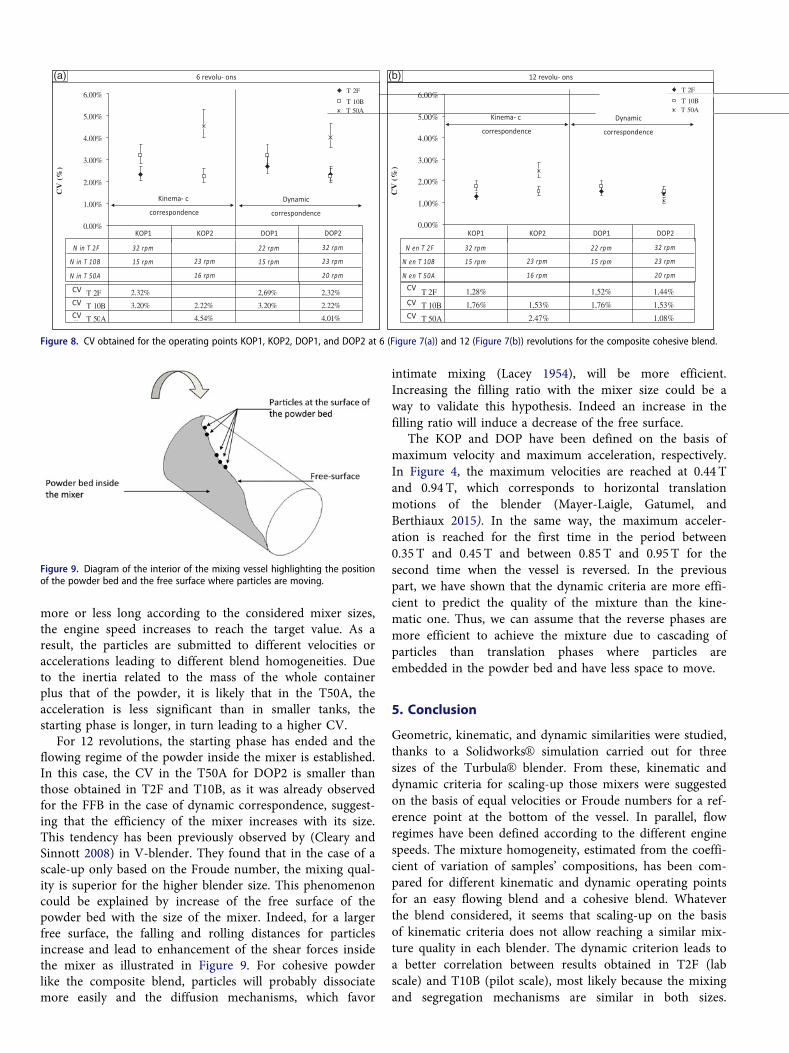
more or less long according to the considered mixer sizes,the engine speed increases to reach the target value. As aresult, the particles are submitted to different velocities oraccelerations leading to different blend homogeneities. Dueto the inertia related to the mass of the whole containerplus that of the powder, it is likely that in the T50A, theacceleration is less significant than in smaller tanks, thestarting phase is longer, in turn leading to a higher CV.
For 12 revolutions, the starting phase has ended and theflowing regime of the powder inside the mixer is established.In this case, the CV in the T50A for DOP2 is smaller thanthose obtained in T2F and T10B, as it was already observedfor the FFB in the case of dynamic correspondence, suggest-ing that the efficiency of the mixer increases with its size.This tendency has been previously observed by (Cleary andSinnott 2008) in V-blender. They found that in the case of ascale-up only based on the Froude number, the mixing qual-ity is superior for the higher blender size. This phenomenoncould be explained by increase of the free surface of thepowder bed with the size of the mixer. Indeed, for a largerfree surface, the falling and rolling distances for particlesincrease and lead to enhancement of the shear forces insidethe mixer as illustrated in Figure 9. For cohesive powderlike the composite blend, particles will probably dissociatemore easily and the diffusion mechanisms, which favor
intimate mixing (Lacey 1954), will be more efficient.Increasing the filling ratio with the mixer size could be away to validate this hypothesis. Indeed an increase in thefilling ratio will induce a decrease of the free surface.
The KOP and DOP have been defined on the basis ofmaximum velocity and maximum acceleration, respectively.In Figure 4, the maximum velocities are reached at 0.44 Tand 0.94 T, which corresponds to horizontal translationmotions of the blender (Mayer-Laigle, Gatumel, andBerthiaux 2015). In the same way, the maximum acceler-ation is reached for the first time in the period between0.35 T and 0.45 T and between 0.85 T and 0.95 T for thesecond time when the vessel is reversed. In the previouspart, we have shown that the dynamic criteria are more effi-cient to predict the quality of the mixture than the kine-matic one. Thus, we can assume that the reverse phases aremore efficient to achieve the mixture due to cascading ofparticles than translation phases where particles areembedded in the powder bed and have less space to move.
5. Conclusion
Geometric, kinematic, and dynamic similarities were studied,thanks to a SolidworksVR simulation carried out for threesizes of the TurbulaVR blender. From these, kinematic anddynamic criteria for scaling-up those mixers were suggestedon the basis of equal velocities or Froude numbers for a ref-erence point at the bottom of the vessel. In parallel, flowregimes have been defined according to the different enginespeeds. The mixture homogeneity, estimated from the coeffi-cient of variation of samples’ compositions, has been com-pared for different kinematic and dynamic operating pointsfor an easy flowing blend and a cohesive blend. Whateverthe blend considered, it seems that scaling-up on the basisof kinematic criteria does not allow reaching a similar mix-ture quality in each blender. The dynamic criterion leads toa better correlation between results obtained in T2F (labscale) and T10B (pilot scale), most likely because the mixingand segregation mechanisms are similar in both sizes.
-2,00%
-1,00%
0,00%
1,00%
2,00%
3,00%
4,00%
5,00%
6,00%
CV
(%
)
T 2F %23,2%96,2%23,2
T 10B 3,20% 2,22% 3,20% 2,22%
T 50A %10,4%45,4
PFC1 PFC2 PFD1 PFD2
N in T 2F
N in T 10B 32 rpm15 rpm 23 rpm
22 rpm15 rpm
32 rpm23 rpm
KOP1 KOP2 DOP1 DOP2
N in T 50A 16 rpm 20 rpm
Kinema- c
correspondence Dynamic
correspondence
6 revolu- ons
-2,00%
-1,00%
0,00%
1,00%
2,00%
3,00%
4,00%
5,00%
6,00%
CV
(%
)
T 2F %44,1%25,1%82,1
T 10B 1,76% 1,53% 1,76% 1,53%
T 50A %80,1%74,2
PFC1 PFC2 PFD1 PFD2
N en T 2F
N en T 10B 32 rpm15 rpm 23 rpm
22 rpm15 rpm
32 rpm23 rpm
KOP1 KOP2 DOP1 DOP2
N en T 50A 16 rpm 20 rpm
Kinema- c
correspondence Dynamic
correspondence
12 revolu- ons
T 50A
T 2F
T 10BT 50A
T 2F
T 10B
CV CV CV CV
CV
CV
(a) (b)
Figure 8. CV obtained for the operating points KOP1, KOP2, DOP1, and DOP2 at 6 (Figure 7(a)) and 12 (Figure 7(b)) revolutions for the composite cohesive blend.
Figure 9. Diagram of the interior of the mixing vessel highlighting the positionof the powder bed and the free surface where particles are moving.

The scale-up at the industrial scale (T50A) has only beenachieved for the composite cohesive blend and seems lessobvious. Indeed, for short mixing time, the mixture qualityobtained in a T50A is inferior to those obtained at pilot orlab scale. This may be explained by the larger inertia of theT50A which does not allow to reach immediately the setspeed when starting agitation. In contrast, for a longer mix-ing time, the quality of the mixture is slightly higher in thelargest mixers. Indeed the free surface area is markedlyincreased at this scale. It induces greater falling and rollingdistances for particles leading to an increase of shear forcesinside the mixer, favoring diffusion mechanism. A study ofthe influence of the filling ratio may validate this assump-tion and could be performed in further work. In addition,mixing of free-flowing powders like the free-flowing blendin the T50A should complete this work in order to clarifythe effect of segregation mechanisms.
Abbreviations
CV coefficient of variationD50 median particle sizeDI dispersion indexDOP dynamic operating pointFr Froude numberKOP kinematic operating pointIcarr Carr’s indexN Engine speedRH Hausner’s ratioT period of rotation of the tankT2F, T10B,T50A name of the different scales of TurbulaVR mixerqa bulk densityqp packed densityl : mean of sample compositionsr standard deviation of sample compositions
Acknowledgment
We would like to thank Laurent Devriendt for his skillful help duringthe experimental work and Luc Penazzi for his technical support dur-ing the SolidworksVR simulation.
Funding
The authors acknowledge the French agency for research, AgenceNationale de la Recherche (ANR), for its financial support through theMASCOTE project (ref ANR-08- MAPR-0002).
References
Alexander, A., T. Shinbrot, and F. J. Muzzio. 2002. Scaling surfacevelocities in rotating cylinders as a function of vessel radius, rotationrate, and particle size. Powder Technology 126 (2):174–90.
Ammarcha, C., C. Gatumel, J. L. Dirion, M. Cabassud, V. Mizonov,and H. Berthiaux. 2013. Transitory powder flow dynamics duringemptying of a continuous mixer. Chemical Engineering andProcessing: Process Intensification 65:68–75. doi: 10.1016/j.cep.2012.12.004.
Bridgwater, J. 2012. Mixing of powders and granular materials bymechanical means—A perspective. Particuology 10 (4):397–427. doi:10.1016/j.partic.2012.06.002.
Carr, R. L. 1970. Particle behaviour storage and flow. British ChemicalEngineering 15 (12):1541–1549.
Cavinato, M., R. Artoni, M. Bresciani, P. Canu, and A. C. Santomaso.2013. Scale-up effects on flow patterns in the high shear mixing ofcohesive powders. Chemical Engineering Science 102:1–9. doi: 10.1016/j.ces.2013.07.037.
Cleary, P. W., and M. D. Sinnott. 2008. Assessing mixing characteris-tics of particle-mixing and granulation devices. Particuology 6 (6):419–44. doi: 10.1016/j.partic.2008.07.014.
Demeyre, J. F. 2007. Caract�erisation de l’homog�en�eit�e de m�elange depoudres et de l’agitateur en m�elange triaxe. PhD. thesis, Universit�ede Toulouse.
Ding, Y. L., R. N. Forster, J. P. K. Seville, and D. J. Parker. 2001.Scaling relationships for rotating drums. Chemical EngineeringScience 56 (12):3737–50. doi: 10.1016/S0009-2509(01)00092-6.
Hausner, H. H. 1967. Friction condition in a mass of metal powder.International Journal of Powder Metallurgy 3:7–13.
Henein, H., J. K. Brimacombe, and A. P. Watkinson. 1983. The model-ing of transverse solids motion in rotary kilns. MetallurgicalTransactions B 14 (2):207–20. doi: 10.1007/BF02661017.
James, J., M. Cooke, L. Trinh, R. Hou, P. Martin, A. Kowalski, andT. L. Rodgers. 2017. Scale-up of batch rotor–stator mixers. Part 1—power constants. Chemical Engineering Research and Design 124:313–20. doi: 10.1016/j.cherd.2017.06.020.
Kushner, J. 2012. Incorporating Turbula mixers into a blending scale-up model for evaluating the effect of magnesium stearate on tablettensile strength and bulk specific volume. International Journal ofPharmaceutics 429 (1–2):1–11. doi: 10.1016/j.ijpharm.2012.02.040.
Lacey, P. M. C. 1954. Developments in the theory of particle mixing.Journal of Applied Chemistry 4 (5):257–68. doi: 10.1002/jctb.5010040504.
Landin, M., P. York, M. J. Cliff, R. C. Rowe, and A. J. Wigmore. 1996.Scale-up of a pharmaceutical granulation in fixed bowl mixer-granu-lators. International Journal of Pharmaceutics 133 (1–2):127–31. doi:10.1016/0378-5173(95)04427-2.
Langhaar, H. L. 1980. Dimensional analysis and theory of models.Huntington, New York: John Wiley & Sons.
Marmur, B. L., and T. J. Heindel. 2017. Scale effects on double-screwgranular mixing. Powder Technology 321:74–88. doi: 10.1016/j.pow-tec.2017.07.067.
Massol-Chaudeur, S., H. Berthiaux, and J. A. Dodds. 2002.Experimental study of the mixing kinetics of binary pharmaceuticalpowder mixture in a laboratory hoop mixe. Chemical EngineeringScience 57(19):4053–65. doi: 10.1016/S0009-2509(02)00262-2.
Mayer-Laigle, C., C. Gatumel, and H. Berthiaux. 2015. Mixing dynam-ics for easy flowing powders in a lab scale TurbulaVR mixer.Chemical Engineering Research and Design 95:248–61. doi: 10.1016/j.cherd.2014.11.003.
Mellmann, J. 2001. The transverse motion of solids in rotating cylin-ders—forms of motion and transition behavior. Powder Technology118 (3):251–70. doi: 10.1016/S0032-5910(00)00402-2.
Midoux, N. 1985. M�ecanique et rh�eologie des fluides en g�enie chimi-que. Technique et Documentation. Lavoisier 149–152.
Nakamura, H., Y. Miyazaki, Y. Sato, T. Iwasaki, and S. Watano. 2009.Numerical analysis of similarities of particle behavior in high shearmixer granulators with different vessel sizes. Advanced PowderTechnology 20 (5):493–501. doi: 10.1016/j.apt.2009.05.006.
Qi, F., T. J. Heindel, and M. M. Wright. 2017. Numerical study of par-ticle mixing in a lab-scale screw mixer using the discrete elementmethod. Powder Technology 308:334–45. doi: 10.1016/j.powtec.2016.12.043.
Redaelli, I., F. Ceccato, C. di Prisco, and P. Simonini. 2017. Solid-fluidtransition in granular flows: MPM simulations with a new constitu-tive approach. Procedia Engineering 175:80–5. doi: 10.1016/j.proeng.2017.01.028.
Savage, S. B. 1984. The mechanics of rapid granular flows. Advances inapplied mechanics 24:289–366.

Shah, U. V., V. Karde, C. Ghoroi, and J. Y. Y. Heng. 2017. Influence ofparticle properties on powder bulk behaviour and processability.International Journal of Pharmaceutics 518 (1–2):138–54. doi: 10.1016/j.ijpharm.2016.12.045.
Shenoy, P., F. Innings, K. Tammel, J. Fitzpatrick, and L. Ahrn�e. 2015.Evaluation of a digital colour imaging system for assessing the mix-ture quality of spice powder mixes by comparison with a salt con-ductivity method. Powder Technology 286:48–54. doi: 10.1016/j.powtec.2015.07.034.
Suzuki, Y., T. Kato, Y. Kikkawa, T. Suzuki, N. Wakiyama, and K.Terada. 2015. Scale-up and blender change model for the pharma-ceutical lubricated mixing process. Powder Technology 280:113–8.doi: 10.1016/j.powtec.2015.04.052.
Wohlhart, K. 1981. A dynamic analysis of the Turbula, InternationalSymposium on Gearing and Power Transmissions, Tokyo, 425–430.
Xiao, X.,. Y. Tan, H. Zhang, R. Deng, and S. Jiang. 2017. Experimentaland DEM studies on the particle mixing performance in rotating
drums: Effect of area ratio. Powder Technology 314:182–63. doi: 10.1016/j.powtec.2017.01.044.
Yamamoto, M., S. Ishihara, and J. Kano. 2016. Evaluation of particledensity effect for mixing behavior in a rotating drum mixer byDEM simulation. Advanced Powder Technology 27 (3):864–70. doi:10.1016/j.apt.2015.12.013.
Yang, R. Y., A. B. Yu, L. McElroy, and J. Bao. 2008. Numerical simula-tion of particle dynamics in different flow regimes in a rotatingdrum. Powder Technology 188 (2):170–7. doi: 10.1016/j.powtec.2008.04.081.
Yijie, G., F. J. Muzzio, and M. G. Ierapetritou. 2013. Scale-up strategyfor continuous powder blending process. Powder Technology 235:55–69.
Zhou, Q., and D. A. V. Morton. 2012. Drug–lactose binding aspects inadhesive mixtures: Controlling performance in dry powder inhalerformulations by altering lactose carrier surfaces. Advanced DrugDelivery Reviews 64 (3):275–84. doi: 10.1016/j.addr.2011.07.002.