Embed Size (px)
Citation preview
COURSE PLANNER
Subject : BASIC ELECTRONICS (2110016)
B.E. – First Year – Second Semester
Class:- Electrical -2016 & Computer - 2016
Term: 16/2 (Feb.-17 to May-17)
Faculty: Prof. J. R. PRAJAPATI Prof. S. S. SHAIKH
Prof. K. S. DHIMMAR Prof. M. H. KANSARA Prof. P. V. PATEL
Contents :
1. Course Outcome 2. Course Content [Syllabus] 3. List of Reference Books 4. List of Experiments 5. Major Equipments required for Experiments 6. List of Open Source Softwares and Learning Websites required for
Experiments 7. Active Learning Assignment
Instructions: [1]This set of Assignment-Tutorial consist the collection of questions of past GTU
Question papers.
[2] Attend those questions which are Bold marked and/or frequenly asked in GTU exam.
[3]Students should make a separate Chapter wise Files [write in File Pages] to solve
these Questions.
[4]Students must solve these given set of Assignments by themselves only.
[5]Assessment of given assignment should be done regularly after completion of each
chapter by Students from the respective faculty members.

1. COURSE OUTCOME After completion of the course, the students will be able to:
Determine the behavior of simple passive electrical circuits with independent
voltage and current sources.
Designsimple analog signal processing functions using operational amplifiers.
Design simple combinational and sequential functions using gates and flip-flops.
Explain the functioning of digital system components including DACs, ADCs,
memory and display devices.
Explainthe organization of computer systems and computer networks.
Determinethe properties of simple signal processing systems.
Determinethe behavior of analog and digital communication systems.
Determine the behaviorof simple linear feedback control systems.
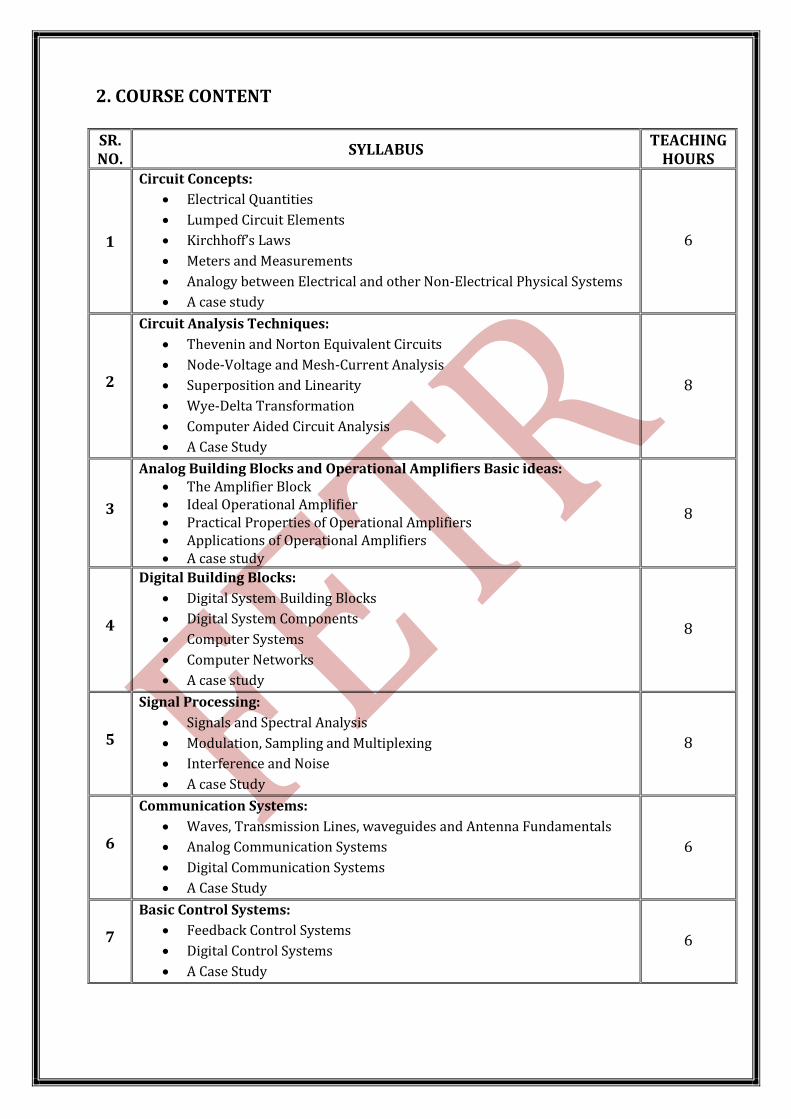
2. COURSE CONTENT SR. NO.
SYLLABUS TEACHING
HOURS
1
Circuit Concepts:
Electrical Quantities
Lumped Circuit Elements
Kirchhoff’s Laws
Meters and Measurements
Analogy between Electrical and other Non-Electrical Physical Systems
A case study
6
2
Circuit Analysis Techniques:
Thevenin and Norton Equivalent Circuits
Node-Voltage and Mesh-Current Analysis
Superposition and Linearity
Wye-Delta Transformation
Computer Aided Circuit Analysis
A Case Study
8
3
Analog Building Blocks and Operational Amplifiers Basic ideas: The Amplifier Block Ideal Operational Amplifier Practical Properties of Operational Amplifiers Applications of Operational Amplifiers A case study
8
4
Digital Building Blocks:
Digital System Building Blocks
Digital System Components
Computer Systems
Computer Networks
A case study
8
5
Signal Processing:
Signals and Spectral Analysis
Modulation, Sampling and Multiplexing
Interference and Noise
A case Study
8
6
Communication Systems:
Waves, Transmission Lines, waveguides and Antenna Fundamentals
Analog Communication Systems
Digital Communication Systems
A Case Study
6
7
Basic Control Systems:
Feedback Control Systems
Digital Control Systems
A Case Study
6

3. REFERENCE BOOKS
1. Introduction to Electrical Engineering, M S Sarma, Oxford University Press
4. LIST OF EXPERIMENTS
SR. NO. NAME OF PRACTICAL
1 TO VERIFY THEVENIN’S THEOREM.
2 TO VERIFY NORTON’S THEOREM.
3 TO STUDY OPERATION OF INVERTING AND NON-INVERTING AMPLIFIER CIRCUITS USING OP-AMP.
4 DESIGN SIMPLE COMBINATIONAL FUNCTIONS AS PER SPECIFICATIONS AND VERIFY THE CORRECTNESS OF THE DESIGN.
5 DESIGN SIMPLE SEQUENTIAL FUNCTIONS AS PER SPECIFICATIONS AND VERIFY THE CORRECTNESS OF THE DESIGN.
6 SIMULATE BASIC PASSIVE ELECTRICAL CIRCUITS USING MULTISIM SIMULATOR AND COMPARE THE SIMULATED RESPONSE WITH THAT OF THE ACTUAL CIRCUIT.
7 SIMULATE ANALOG ELECTRICAL CIRCUIT USING MULTISIM SIMULATOR AND COMPARE THE SIMULATED RESPONSE WITH THAT OF THE ACTUAL CIRCUIT.
8 SIMULATE COMBINATIONAL CIRCUIT USING MULTISIM SIMULATOR AND COMPARE THE SIMULATED RESPONSE WITH THAT OF THE ACTUAL CIRCUIT.
9 SIMULATE SEQUENTIAL CIRCUIT USING MULTISIM SIMULATOR AND COMPARE THE SIMULATED RESPONSE WITH THAT OF THE ACTUAL CIRCUIT.
10 SIMULATE MODULATION AND DEMODULATION CIRCUIT USING MULTISIM SIMULATOR.
11 SIMULATE SAMPLING AND MULTIPLEXING CIRCUIT USING MULTISIM SIMULATOR.

5. MAJOR EQUIPMENTS REQUIRED FOR EXPERIMENTS Analog, Digital & Network theory Trainer Kits
Thevenin’s & Norton’s theorems trainer kit Inverting and Non-inverting Amplifier using IC741 op-amp trainer kit Verification of Boolean expression using basic logic gates trainer kit Half Adder and full Adder trainer kit Flip-flops [SR, JK, D & T] trainer kit
20MHz, Two channel Cathode ray oscilloscope Function Generator (Frequency range up to 20 MHz) with sine, square, triangle
etc… wave output 2x0-30V/1A variable & 5V fixed multichannel Power Supply 0- 1.5- 3V portable moving coil type DC Voltmeter 0- 7.5- 15V portable moving coil type DC Voltmeter 0-750Micro Amp portable moving coil type DC Ammeter 0-100- 200 Mili Amp portable moving coil type DC Ammeter Digital Multimeter 15 S 100MHz, 1GS/s color Digital Storage Oscilloscope with FFT Various Electronics Components including different types of Op Amps and digital
ICs. PCs:
Intel core i5 CPU 500 GB Hard disk 4 GB DDR-3 RAM 18.5” LCD Monitor Keyboard, Mouse

6. LIST OF OPEN SOURCE SOFTWARES AND LEARNING WEBSITES
REQUIRED FOR EXPERIMENTS Software:
Multisim and SciLab (www.scilab.org)
Learning Material:
http://nptel.iitm.ac.in/ www.spoken-tutotial.org
7. ACTIVE LEARNING ASSIGNMENT
Chapter-1
Circuit Concepts:
Electrical Quantities
Lumped Circuit Elements
Kirchhoff’s Laws
Meters and Measurements
Analogy between Electrical and other Non-Electrical Physical Systems
A case study
ATTEMPTSEVEN QUESTIONS: SR
NO. QUESTION YEAR MARKS
1
Objective Questions 1.In hydraulic system, Quantity named Flow is described as a Output flow rate Fo , and in electrical quantity it is described as a____.
(a) Voltage(b) Current(c) Capacitance(d) Inductance
June-14 01
2 Explain in brief about Lumped circuit elements called
resistor and capacitor. June-14 07
3 Write a short note on Ammeter and Voltmeter. June-14 04
4
Objective Question (MCQ) 1.Ohm’s law (V = IR)
(a) Can be applied to a.c similar to that of d.c. (b) Can be applied to a.c. but after replacing R by Z (impedance) (c) Can never be applied to a.c (d) None of the above
2.Conductance is expressed in terms of (a) ohm / m (b) m / ohm (c) mho / m (d) mho
3.Which resistor will be physically larger in size? (a) 10 ohm, 50 W (b) 100 ohm, 10 W (c) 1 kohm, 1 W (d) 10 Mohm, 1/ 2 W
June-15 03
5 Write a short note on Cathode Ray Oscilloscope. June-15 04
6
Objective Question (MCQ) 1.Which component has a positive and a negative side?
(a) A potentiometer (b) A fuse (c) A resistor (d) A battery 2.To increase the current capacity of a cell, several cells should be
connected in: (a) parallel (b) series (c) parallel resonant (d) series resonant
3.Which tolerance rating would a high-quality resistor have? (a) 5% (b) 10% (c) 20% (d) 0.1%
4.What does a common multimeter measure? (a) Resistance, capacitance and inductance (b) Voltage, current and resistance (c) Resistance and reactance (d) SWR and power
5.Potential difference is measured by means of: (a) a wattmeter(b) an ohmmeter(c) a voltmeter(d) an ammeter
6.A resistor in a circuit becomes very hot and starts to burn. This is because the resistor is dissipating too much:
(a) voltage (b) resistance (c) current (d) power
Dec.-15 06
7 Explain in brief about Dot Convention. Dec.-15 03 8 Write a short note on Oscilloscope. Dec.-15 04

9 Classify the controlled source and draw schematics for each. Dec.-15 03
10
Objective Question (MCQ) 1.Power is defined as the rate of transfer of ___ with respect to time.
(a) Charge (b) Current (c) Energy (d) Voltage 2.Mesh analysis is based on
(a) KVL (b) KCL (c) Both (d) Law of conversion of energy 3.If the network elements such as resistances, capacitances,
inductances are not physically separable, then it is known as (a) Lumped Network (b) Distributed Network (c) Unilateral Network (d) Bilateral Network
June-16 03
11 Explain Coulomb’s First and Second Law. June-16 03 12 Explain Kirchhoff’s Voltage law and Current law in Short. June-16 04
13
Objective Question (MCQ) 1.In an Electrical system, the flow of current follows:
(a) De Morgan’s law (b) Boyle’s law (c)Curie’s law (d) Ohm’s law 2.If a 1 Hz square signal is given to a bulb, how long will it glow?
(a) 1second (b) 2 second (c) 0.5 second (d) 0 second 3.The inductance offered by a inductor of 1 H to a DC signal is
(a) 0 (b) infinity (c) 1 (d) indeterminate 4.A circuit that converts AC signal to DC signal is known as a (a) Rectifier circuit (b) Inverter circuit (c) RL circuit (d) RC circuit
Jan.-17 04
14
Define Resistor. Quote all the characteristics of any resistor. If you go to the market to purchase a resistor, apart from resistance what else will you quote so that the safety is ensured?
Jan.-17 03
15 How does a Voltmeter differ from an Ammeter? Jan.-17 04
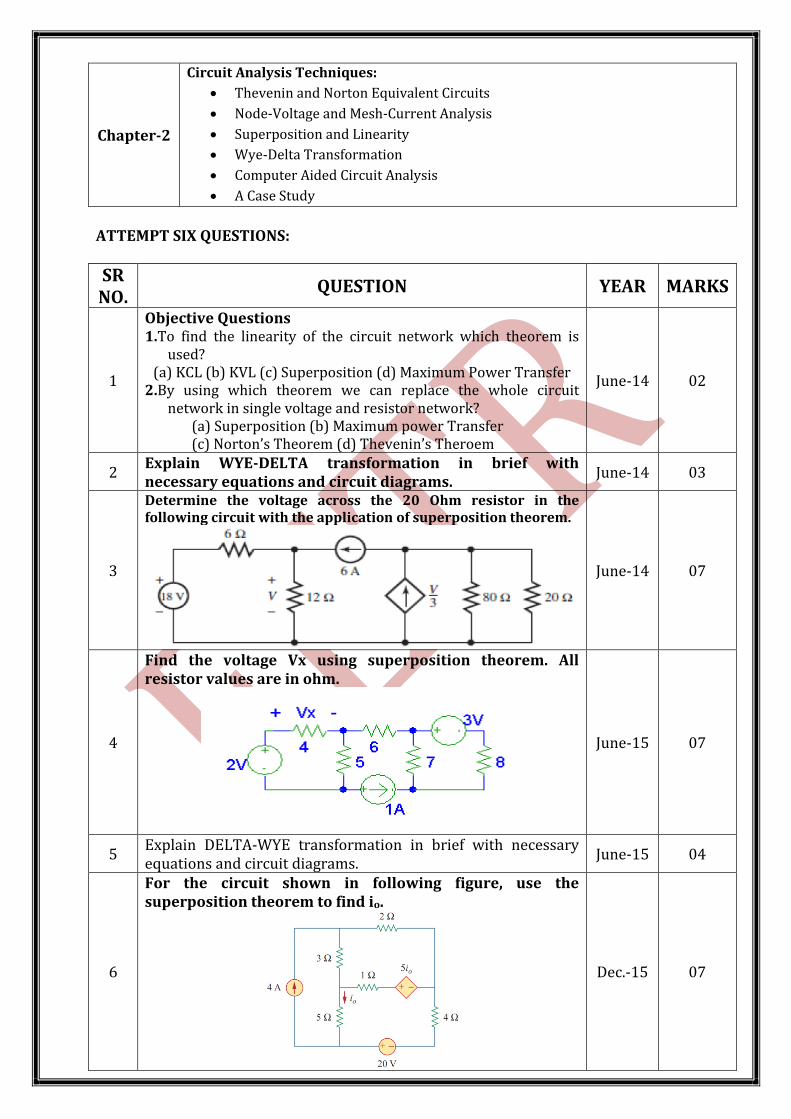
Chapter-2
Circuit Analysis Techniques:
Thevenin and Norton Equivalent Circuits
Node-Voltage and Mesh-Current Analysis
Superposition and Linearity
Wye-Delta Transformation
Computer Aided Circuit Analysis
A Case Study
ATTEMPT SIX QUESTIONS:
SR NO.
QUESTION YEAR MARKS
1
Objective Questions 1.To find the linearity of the circuit network which theorem is
used? (a) KCL (b) KVL (c) Superposition (d) Maximum Power Transfer
2.By using which theorem we can replace the whole circuit network in single voltage and resistor network?
(a) Superposition (b) Maximum power Transfer (c) Norton’s Theorem (d) Thevenin’s Theroem
June-14 02
2 Explain WYE-DELTA transformation in brief with necessary equations and circuit diagrams.
June-14 03
3
Determine the voltage across the 20 Ohm resistor in the following circuit with the application of superposition theorem.
June-14 07
4
Find the voltage Vx using superposition theorem. All resistor values are in ohm.
June-15 07
5 Explain DELTA-WYE transformation in brief with necessary equations and circuit diagrams.
June-15 04
6
For the circuit shown in following figure, use the superposition theorem to find io.
Dec.-15 07
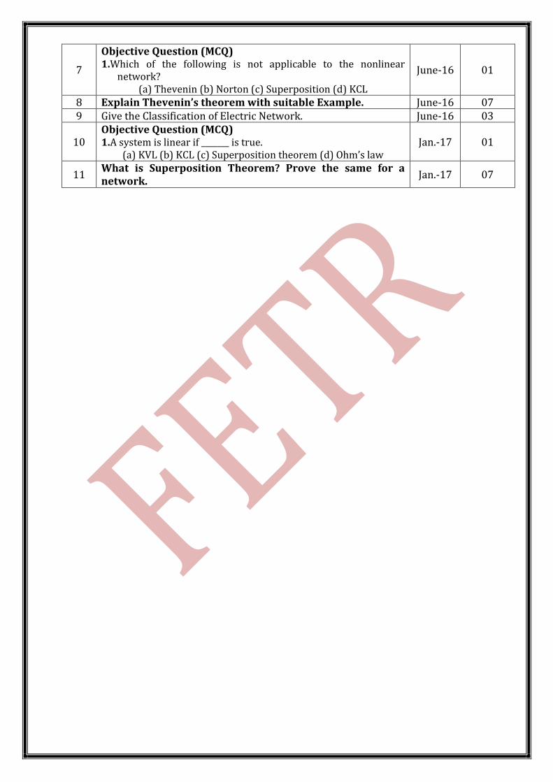
7
Objective Question (MCQ) 1.Which of the following is not applicable to the nonlinear
network? (a) Thevenin (b) Norton (c) Superposition (d) KCL
June-16 01
8 Explain Thevenin’s theorem with suitable Example. June-16 07 9 Give the Classification of Electric Network. June-16 03
10 Objective Question (MCQ) 1.A system is linear if _______ is true.
(a) KVL (b) KCL (c) Superposition theorem (d) Ohm’s law Jan.-17 01
11 What is Superposition Theorem? Prove the same for a network.
Jan.-17 07

Chapter-3
Analog Building Blocks and Operational Amplifiers Basic ideas: The Amplifier Block Ideal Operational Amplifier Practical Properties of Operational Amplifiers Applications of Operational Amplifiers A case study
ATTEMPT NINE QUESTIONS:
SR NO.
QUESTION YEAR MARKS
1
Objective Questions 1.For the operational amplifier with inverting configuration the
change in the phase of the output voltage is __________. (a) 180o (b) 90o(c) 270o (d) 45o
2.Which one is the Linear application design by Op-amp ? (a) Integrator (b) Voltage Regulator (c) Multiplier (d) Comparator
June-14 02
2 Write about Differential amplifier using Op-amp with necessary circuit diagram and equations.
June-14 07
3 Describe band pass active filter using Operational amplifier with necessary diagrams and equations.
June-14 07
4
Objective Question (MCQ) 1.The circuit which magnifies a small input signal without
changing its shape is called an ____________ (a) Linear amplifier (b) Power Amplifier (c) Non-linear Amplifier (d) None of Above
2.IC741 use a ________ polarity supply. (a) Dual (b) Single (c) Negative (d) None of Above
June-15 02
5 Draw circuit diagram of non-inverting operational amplifier & explain in brief.
June-15 03
6 Describe low pass active filter using Operational amplifier with necessary diagrams and equations.
June-15 07
7
Objective Question (MCQ) 1.In most of modern IC op-amps, the 741 requires _____ power
supplies (a) 1 (b) 2 (c) 3 (d) 4
2.A circuit designed to increase the level of its input signal is called: (a) an amplifier (b) a modulator (c) an oscillator (d) a receiver
Dec.-15 02
8 Explain in brief following properties of operational amplifier.
(a) Input Resistance (b) Open Loop Voltage gain (c) CMRR (d) Input Offset Voltage
Dec.-15 04
9 Write about ideal operational amplifier with necessary circuit diagram and equations.
Dec.-15 07
10 Why differential amplifier is necessary? Dec.-15 03
11
Objective Question (MCQ) 1.For Non inverting amplifier the phase shift between input and
output is (a) 270° (b) 45° (c) 180° (d) 0°
2.Which one is Linear Application of Op-Amp? (a) Comparator(b) Differentiator (c) Schmitt trigger (d) Log Amplifier
June-16 02
12 Explain ideal characteristics of ideal Op-Amp in detail. June-16 07 13 Explain inverting configuration of Op-Amp. June-16 04
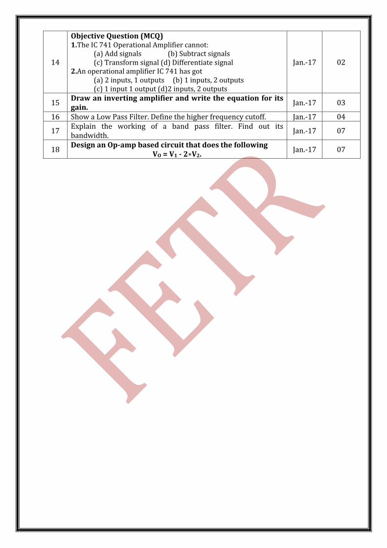
14
Objective Question (MCQ) 1.The IC 741 Operational Amplifier cannot:
(a) Add signals (b) Subtract signals (c) Transform signal (d) Differentiate signal
2.An operational amplifier IC 741 has got (a) 2 inputs, 1 outputs (b) 1 inputs, 2 outputs (c) 1 input 1 output (d)2 inputs, 2 outputs
Jan.-17 02
15 Draw an inverting amplifier and write the equation for its gain.
Jan.-17 03
16 Show a Low Pass Filter. Define the higher frequency cutoff. Jan.-17 04
17 Explain the working of a band pass filter. Find out its bandwidth.
Jan.-17 07
18 Design an Op-amp based circuit that does the following
VO = V1 - 2∗V2. Jan.-17 07
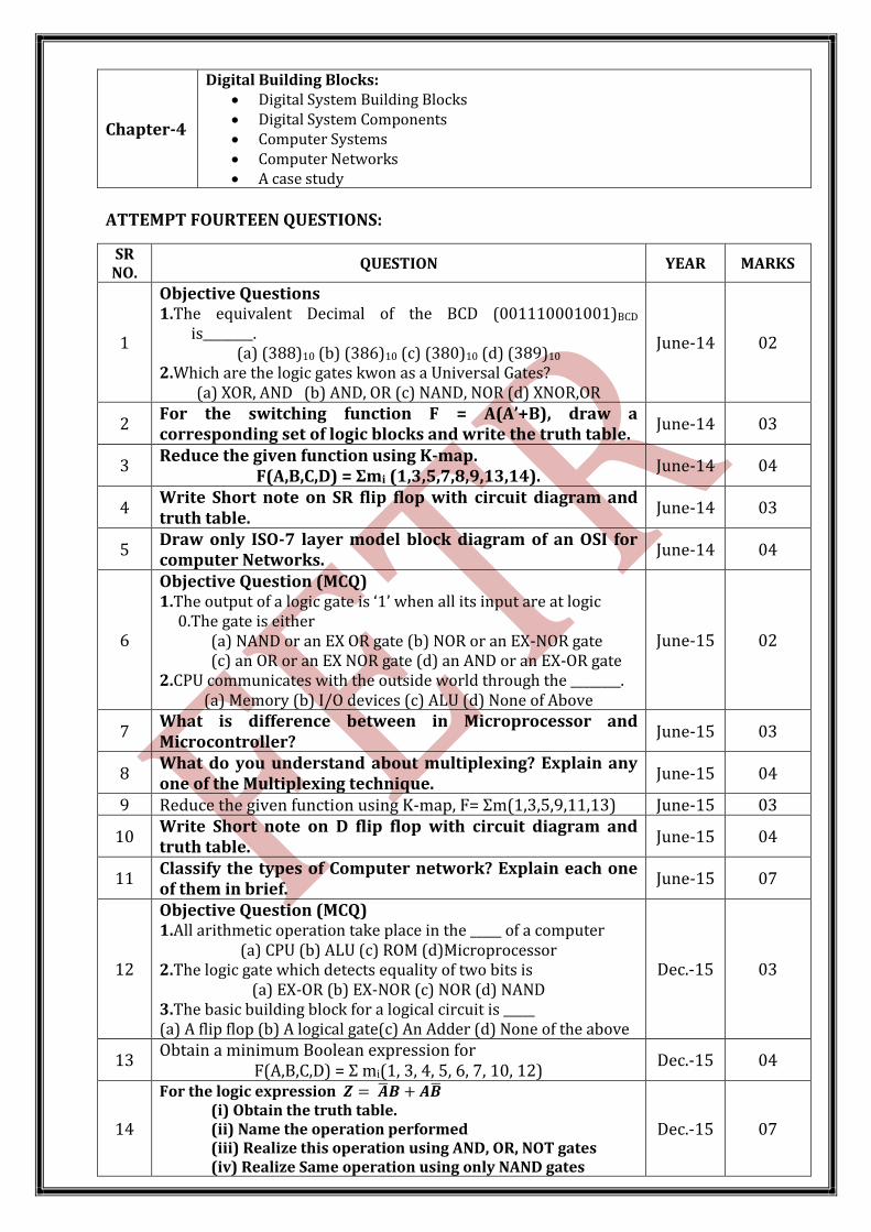
Chapter-4
Digital Building Blocks: Digital System Building Blocks Digital System Components Computer Systems Computer Networks A case study
ATTEMPT FOURTEEN QUESTIONS:
SR NO.
QUESTION YEAR MARKS
1
Objective Questions 1.The equivalent Decimal of the BCD (001110001001)BCD
is________. (a) (388)10 (b) (386)10 (c) (380)10 (d) (389)10
2.Which are the logic gates kwon as a Universal Gates? (a) XOR, AND (b) AND, OR (c) NAND, NOR (d) XNOR,OR
June-14 02
2 For the switching function F = A(A’+B), draw a corresponding set of logic blocks and write the truth table.
June-14 03
3 Reduce the given function using K-map.
F(A,B,C,D) = Σmi (1,3,5,7,8,9,13,14). June-14 04
4 Write Short note on SR flip flop with circuit diagram and truth table.
June-14 03
5 Draw only ISO-7 layer model block diagram of an OSI for computer Networks.
June-14 04
6
Objective Question (MCQ) 1.The output of a logic gate is ‘1’ when all its input are at logic
0.The gate is either (a) NAND or an EX OR gate (b) NOR or an EX-NOR gate (c) an OR or an EX NOR gate (d) an AND or an EX-OR gate
2.CPU communicates with the outside world through the ________. (a) Memory (b) I/O devices (c) ALU (d) None of Above
June-15 02
7 What is difference between in Microprocessor and Microcontroller?
June-15 03
8 What do you understand about multiplexing? Explain any one of the Multiplexing technique.
June-15 04
9 Reduce the given function using K-map, F= Σm(1,3,5,9,11,13) June-15 03
10 Write Short note on D flip flop with circuit diagram and truth table.
June-15 04
11 Classify the types of Computer network? Explain each one of them in brief.
June-15 07
12
Objective Question (MCQ) 1.All arithmetic operation take place in the _____ of a computer
(a) CPU (b) ALU (c) ROM (d)Microprocessor 2.The logic gate which detects equality of two bits is
(a) EX-OR (b) EX-NOR (c) NOR (d) NAND 3.The basic building block for a logical circuit is _____ (a) A flip flop (b) A logical gate(c) An Adder (d) None of the above
Dec.-15 03
13 Obtain a minimum Boolean expression for
F(A,B,C,D) = Σ mi(1, 3, 4, 5, 6, 7, 10, 12) Dec.-15 04
14
For the logic expression 𝒁 = 𝑨 𝑩 + 𝑨𝑩 (i) Obtain the truth table. (ii) Name the operation performed (iii) Realize this operation using AND, OR, NOT gates (iv) Realize Same operation using only NAND gates
Dec.-15 07

15 Classify display devices. Dec.-15 03 16 Classify network topologies and draw each one of them. Dec.-15 04 17 Draw and explain microprocessor system architecture. Dec.-15 07
18
Objective Question (MCQ) 1.The decimal equivalent of Binary (1111110) is
(a) 125 (b) 128 (c) 255 (d) 126 2.The Digital Circuit which accepts many input and produces only
one output is known as (a) Encoder (d) Demultiplexer (c) Multiplexer (d) Decoder
June-16 02
19 Draw the logic symbol and truth table of following gates.
1. AND 2. OR 3. EX-OR 4. NOR June-16 04
20 Write short note on JK flip flop with logic diagram and truth table.
June-16 07
21 Reduce the given Boolean expression using K-map.
F(A,B,C) = Σm(0,2,3,5) June-16 03
22 Write short note on Star topology. June-16 04
23
Objective Question (MCQ) 1.The equivalent octal of the binary number (101010101011)2 is
(a) (5352)8(b) (2523)8(c) (5253)8(d) (225253)8 2.Following gates are known as Universal Logic Gates
(a) AND, OR (b) NAND, NOR (c) AND, NOR (d) NAND,OR 3.A Flip Flop has got a memory of
(a) 1 bit (b) 2 bit (c) 4 bit (d) 8 bit
Jan.-17 03
24 Assign a binary code to all the 52 playing cards. Use minimum number of bits.
Jan.-17 03
25 State and Prove De Morgan’s laws. Jan.-17 04 26 Draw an SR Flip Flop. Plot its truth table and Symbol. Jan.-17 03
27 Draw the block diagram of a multiplexer circuit and label the pins.
Jan.-17 04
28 Draw the ISO- 7 layer block diagram for Computer Network Jan.-17 03 29 Discuss the types of Computer Networks. Jan.-17 07

Chapter-5
Signal Processing:
Signals and Spectral Analysis
Modulation, Sampling and Multiplexing
Interference and Noise
A case Study
ATTEMPT FIVE QUESTIONS:
SR NO.
QUESTION YEAR MARKS
1
Objective Questions 1.In the given pulse modulations, which one is not the type of
pulse modulation? (a) PWM (b) PSK (c) PPM (d) PAM
2.Even signals are stratify the property for signal x(t)=_______. (a) x(-t) (b) -x(t) (c) -x(t)/4 (d) -x(t)/2
3.In Which process Sampling is used? (a) Frequency Division (b) Signal amplification (c) Signal attenuation (d) Digital Modulation
June-14 03
2 Explain in detail Pulse modulation with necessary diagrams.
June-14 07
3 Draw only functional block diagram of signal processing system.
June-14 03
4
Objective Question (MCQ) 1.The frequency that has the longest period is
(a) 10 KHz (b) 1 KHz (c) 10 Hz (d) 1 Hz 2.Out of following signals __________ is an even signal.
(a) Cosine wave (b) Sine wave (c) Triangle wave (d) None of the above.
3.PCM is a _________Pulse Modulation Technique. (a) Analog (b) Digital (c) Hybrid (d) None of Above
June-15 03
5 Define The following Terms.
(a) Interference (b) Mutual Inductance (c) Noise Margin June-15 03
6 State the need of modulation and what are the other advantages of modulation in communication system?
Dec.-15 07
7
Objective Question (MCQ) 1.Out of following signal,_______ is a Random Signal.
(a) Sine Wave (b) Cosine Wave (c) Noise (d) Triangle Wave 2.The antisymmetrical signal is also known as ________ Signal.
(a) Even (b) Odd (c) Energy (d) Power 3.Out of following ________ is digital Pulse Modulation.
(a) PAM (b) PPM (c) PCM (d) PWM
June-16 03
8 Give the classification of signals. June-16 03
9 What is multiplexing? Compare FDM and TDM June-16 03
10
Objective Question (MCQ) 1.X(t)= - X(t) is the property of
(a) Even signal (b) Odd signal (c)Periodic signal(d) Aperiodic signal
2.PAM stands for (a) Pulse And Modulation (b) Pulse Analog Modulation (c) Pulse Altitude Modulation (d) Pulse Amplitude Modulation
Jan.-17 02
11 How does a PAM signal differ from a PWM, PPM signal? Jan.-17 07
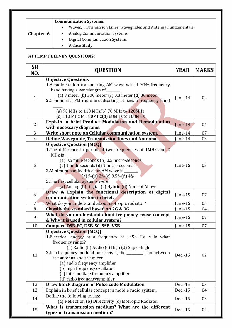
Chapter-6
Communication Systems:
Waves, Transmission Lines, waveguides and Antenna Fundamentals
Analog Communication Systems
Digital Communication Systems
A Case Study
ATTEMPT ELEVEN QUESTIONS:
SR NO.
QUESTION YEAR MARKS
1
Objective Questions 1.A radio station transmitting AM wave with 1 MHz frequency
band having a wavelength of ________. (a) 3 meter (b) 300 meter (c) 0.3 meter (d) 30 meter
2.Commercial FM radio broadcasting utilizes a frequency band ______.
(a) 90 MHz to 110 MHz(b) 70 MHz to 120MHz (c) 110 MHz to 180MHz(d) 88MHz to 108MHz
June-14 02
2 Explain in brief Product Modulation and Demodulation with necessary diagrams.
June-14 04
3 Write short note on Cellular communication system. June-14 07 4 Define Waveguide, Transmission lines and Antenna. June-14 03
5
Objective Question (MCQ) 1.The difference in period of two frequencies of 1MHz and 2
MHz is (a) 0.5 milli-seconds (b) 0.5 micro-seconds (c) 1 milli-seconds (d) 1 micro-seconds
2.Minimum bandwidth of an AM wave is ________. (a) fm(b) 2fm(c) 0.5fm(d) 4fm
3.The first cellular systems were ___________. (a) Analog (b) Digital (c) Hybrid (d) None of Above
June-15 03
6 Draw & Explain the functional description of digital communication system in brief.
June-15 07
7 What do you understand about isotropic radiator? June-15 03 8 Classify the standard based on 2G & 3G. June-15 04
9 What do you understand about frequency reuse concept & Why it is used in cellular system?
June-15 07
10 Compare DSB-FC, DSB-SC, SSB, VSB. June-15 07
11
Objective Question (MCQ) 1.Electrical energy at a frequency of 1454 Hz is in what
frequency range? (a) Radio (b) Audio (c) High (d) Super-high
2.In a frequency modulation receiver, the __________ is in between the antenna and the mixer.
(a) audio frequency amplifier (b) high frequency oscillator (c) intermediate frequency amplifier (d) radio frequencyamplifier
Dec.-15 02
12 Draw block diagram of Pulse code Modulation. Dec.-15 03 13 Explain in brief cellular concept in mobile radio system. Dec.-15 04
14 Define the following terms:
(a) Reflection (b) Directivity (c) Isotropic Radiator Dec.-15 03
15 What is transmission medium? What are the different types of transmission medium?
Dec.-15 04
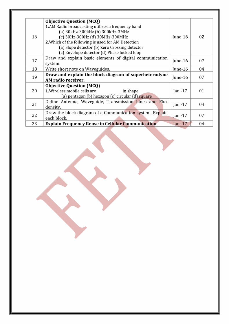
16
Objective Question (MCQ) 1.AM Radio broadcasting utilizes a frequency band
(a) 30kHz-300kHz (b) 300kHz-3MHz (c) 30Hz-300Hz (d) 30MHz-300MHz
2.Which of the following is used for AM Detection (a) Slope detector (b) Zero Crossing detector (c) Envelope detector (d) Phase locked loop
June-16 02
17 Draw and explain basic elements of digital communication system.
June-16 07
18 Write short note on Waveguides. June-16 04
19 Draw and explain the block diagram of superheterodyne AM radio receiver.
June-16 07
20 Objective Question (MCQ) 1.Wireless mobile cells are _______________ in shape
(a) pentagon (b) hexagon (c) circular (d) square Jan.-17 01
21 Define Antenna, Waveguide, Transmission Lines and Flux density.
Jan.-17 04
22 Draw the block diagram of a Communication system. Explain each block.
Jan.-17 07
23 Explain Frequency Reuse in Cellular Communication Jan.-17 04
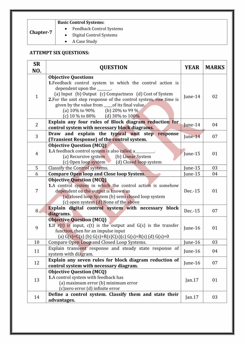
Chapter-7
Basic Control Systems:
Feedback Control Systems
Digital Control Systems
A Case Study
ATTEMPT SIX QUESTIONS:
SR NO.
QUESTION YEAR MARKS
1
Objective Questions 1.Feedback control system in which the control action is
dependent upon the ________. (a) Input (b) Output (c) Compactness (d) Cost of System
2.For the unit step response of the control system, rise time is given by the value from _____of its final value.
(a) 10% to 90% (b) 20% to 99 % (c) 10 % to 80% (d) 30% to 100%
June-14 02
2 Explain any four rules of Block diagram reduction for control system with necessary block diagrams.
June-14 04
3 Draw and explain the typical unit step response (Transient Response) of the control system.
June-14 07
4
Objective Question (MCQ) 1.A feedback control system is also called a___________.
(a) Recursive system (b) Linear System (c) Open loop system (d) Closed loop system
June-15 01
5 Classify the Control systems. June-15 03 6 Compare Open loop and Close loop System. June-15 04
7
Objective Question (MCQ) 1.A control system in which the control action is somehow
dependent on the output is known as (a) closed loop System (b) semi closed loop system (c) open system (d) None of the above
Dec.-15 01
8 Explain digital control system with necessary block diagrams.
Dec.-15 07
9
Objective Question (MCQ) 1.If r(t) is input, c(t) is the output and G(s) is the transfer
function, then for an impulse input (a) G(s)=C(s) (b) G(s)=R(s)C(s)(c) G(s)=R(s) (d) G(s)=0
June-16 01
10 Compare Open Loop and Closed Loop Systems. June-16 03
11 Explain transient response and steady state response of system with diagram.
June-16 04
12 Explain any seven rules for block diagram reduction of control system with necessary diagram.
June-16 07
13
Objective Question (MCQ) 1.A control system with feedback has
(a) maximum error (b) minimum error (c)zero error (d) infinite error
Jan.17 01
14 Define a control system. Classify them and state their advantages.
Jan.17 03