Embed Size (px)
Citation preview
Classes of Electron Guns and
Injectors• The objective of this lecture is to classify and describe the various
types of electron guns and injectors. This Lecture describes some
historical as well as contemporary examples of guns and
injectors.
• The student will learn about the different types of guns and
injectors, and their performance properties. And be able to match
an injector design with its optimum application.
Thermionic cathode
Gridded-DC gun
DC gun
NCRF gun
Photo-electric cathode
DC gun
NCRF gun
SRF gun
Field-emission cathode
Pulsed-DC
RF
Pulsed-DC+
NCRF
Emittance compensation
Solenoid focusing
RF focusing
Slice phase space matching
Ballistic compression
Fundamental &
sub-harmonic RF
Inductive linac
Magnetic compression
RF harmonic linearizing
RF compression
Solenoid focusing
Tapered RF phase bunching
Capture into booster
Emittance preservation
Longitudinal phase space
compensation
Chirping for bunch
compressors
Emission &
Initial AccelerationBeam Conditioning
Acceleration
High Brightness Electron Injectors for
Light Sources – June 14-18, 2010
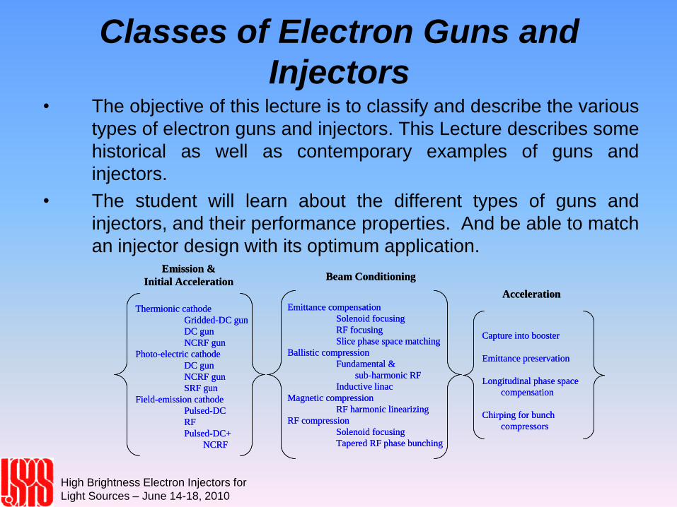
Thermionic Injectors (1)
• The first injectors for free electron lasers were all thermionic and the
first injector specifically built for an fel was a gridded thermionic gun
followed by stages of ballistic compressors to reduce the gun bunch
length from 1 ns to 12 ps. The basic configuration is shown in the
next slide. The injector was ~3 meters long to accommodate the
components and drift lengths for compression. Typical gun voltages
were between 50 to 100 kV and the cathode grid was biased by a
tuned, delay line similar to that used in a pulse forming network. In
order to increase the charge captured into each rf bucket, the
bunchers take the charge the gun emits in a ns and compresses it
into a 12 ps long bunch. This is done by beginning with a low
enough rf frequency to produce a linear energy chirp on the 1ns long
beam. In this example the 12th sub-harmonic is used as it has a
period of 9 ns, thus its rf waveform is fairly linear near the zero
crossing over the 1 ns beam. The second stage is another rf
buncher cavity now at 1/3rd harmonic followed by a drift length to
produce a 50 ps long bunch at the entrance to the TPV buncher.
High Brightness Electron Injectors for
Light Sources – June 14-18, 2010
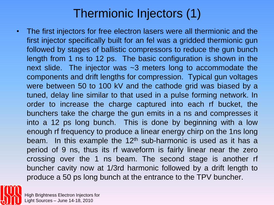
Thermionic Injectors(2)
High Brightness Electron Injectors for
Light Sources – June 14-18, 2010
Schematic of the
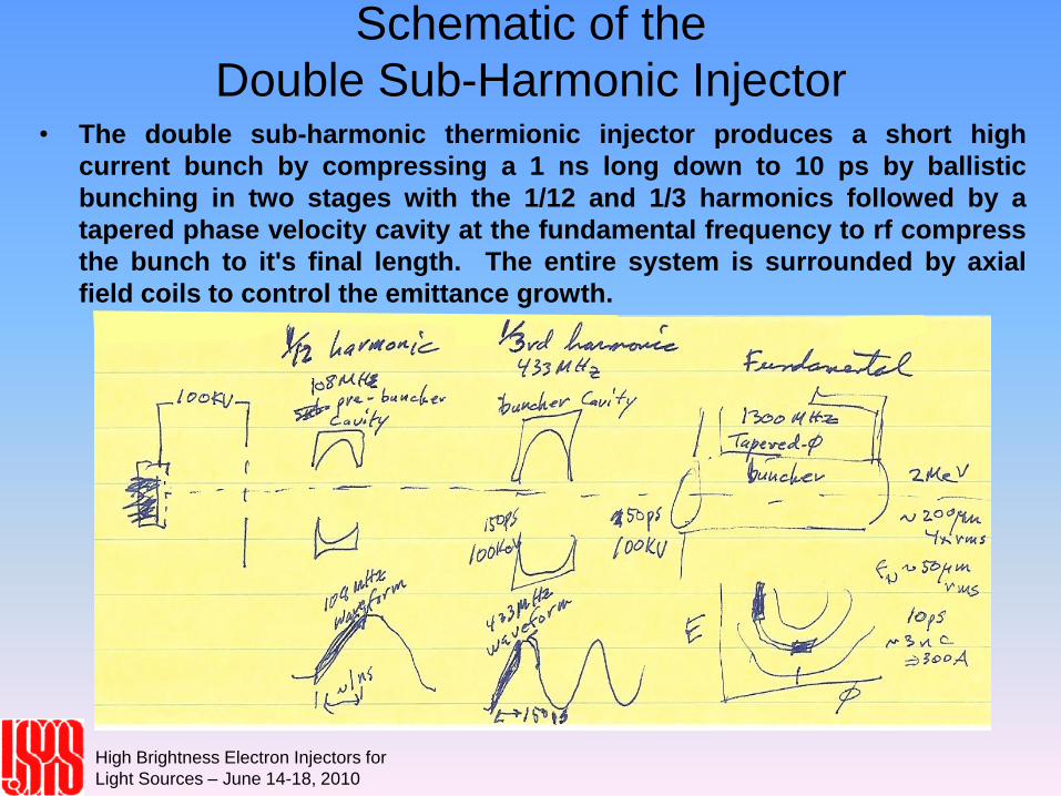
Double Sub-Harmonic Injector• The double sub-harmonic thermionic injector produces a short high
current bunch by compressing a 1 ns long down to 10 ps by ballistic
bunching in two stages with the 1/12 and 1/3 harmonics followed by a
tapered phase velocity cavity at the fundamental frequency to rf compress
the bunch to it's final length. The entire system is surrounded by axial
field coils to control the emittance growth.
High Brightness Electron Injectors for
Light Sources – June 14-18, 2010
Lecture 11
D.H. Dowell, S. Lidia, J.F. Schmerge
Thermionic Injector Specifications
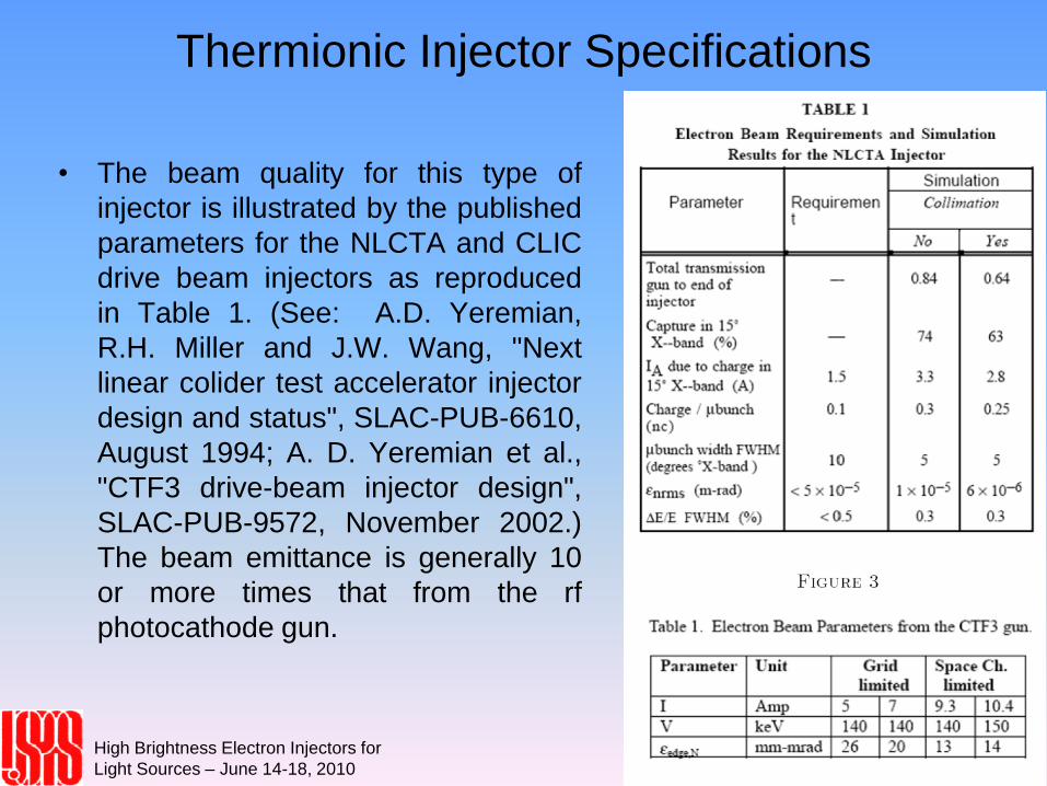
• The beam quality for this type of
injector is illustrated by the published
parameters for the NLCTA and CLIC
drive beam injectors as reproduced
in Table 1. (See: A.D. Yeremian,
R.H. Miller and J.W. Wang, "Next
linear colider test accelerator injector
design and status", SLAC-PUB-6610,
August 1994; A. D. Yeremian et al.,
"CTF3 drive-beam injector design",
SLAC-PUB-9572, November 2002.)
The beam emittance is generally 10
or more times that from the rf
photocathode gun.
High Brightness Electron Injectors for
Light Sources – June 14-18, 2010
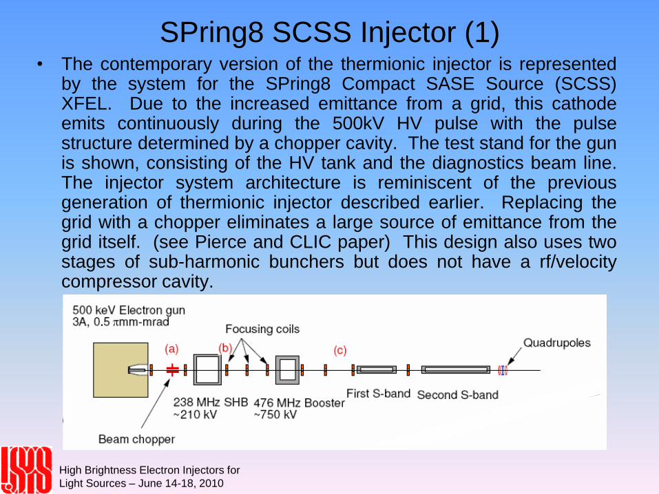
SPring8 SCSS Injector (1)• The contemporary version of the thermionic injector is represented
by the system for the SPring8 Compact SASE Source (SCSS)XFEL. Due to the increased emittance from a grid, this cathodeemits continuously during the 500kV HV pulse with the pulsestructure determined by a chopper cavity. The test stand for the gunis shown, consisting of the HV tank and the diagnostics beam line.The injector system architecture is reminiscent of the previousgeneration of thermionic injector described earlier. Replacing thegrid with a chopper eliminates a large source of emittance from thegrid itself. (see Pierce and CLIC paper) This design also uses twostages of sub-harmonic bunchers but does not have a rf/velocitycompressor cavity.
High Brightness Electron Injectors for
Light Sources – June 14-18, 2010
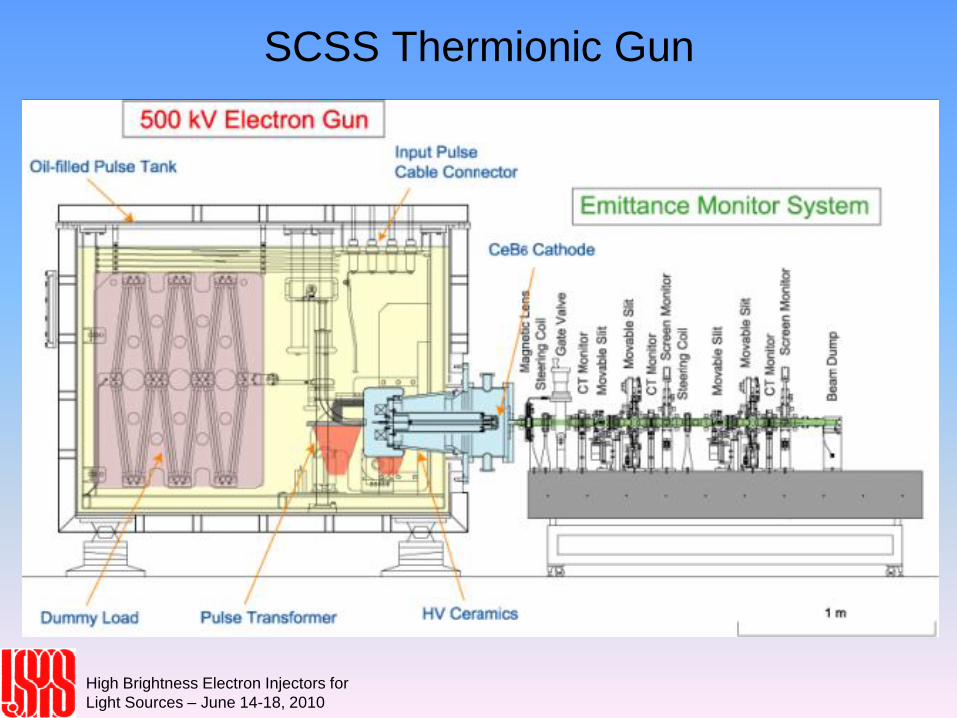
SCSS Thermionic Gun
High Brightness Electron Injectors for
Light Sources – June 14-18, 2010
Lecture 11
D.H. Dowell, S. Lidia, J.F. Schmerge
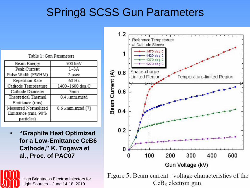
SPring8 SCSS Gun Parameters
• “Graphite Heat Optimized
for a Low-Emittance CeB6
Cathode,” K. Togawa et
al., Proc. of PAC07
High Brightness Electron Injectors for
Light Sources – June 14-18, 2010
Lecture 11
D.H. Dowell, S. Lidia, J.F. Schmerge
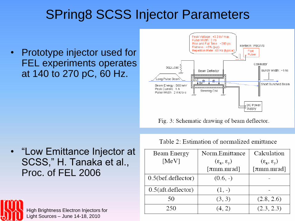
SPring8 SCSS Injector Parameters
• Prototype injector used for FEL experiments operates at 140 to 270 pC, 60 Hz.
• “Low Emittance Injector at SCSS,” H. Tanaka et al., Proc. of FEL 2006
High Brightness Electron Injectors for
Light Sources – June 14-18, 2010
DC Photocathode Guns and
GaAs(Cs) Cathodes• The DC photocathode gun was first developed as a source of
polarized electrons for high-energy physics experiments. The cathodematerial was and remains cesciated gallium arsenide, GaAs(Cs),which produces polarized electrons with the same helicity as that ofthe incident laser photons. Polarizations greater than 90 percent havebeen achieved from sophisticated wafers consisting of alternatinglayers of epitaxially grown structures gallium and arsenic. Thesenegative electron affinity (NEA) cathodes have high quantum yields ofa few percent at near IR and visible wavelengths, and the lowestmeasured thermal emittances.
• The disadvantages of GaAs(Cs) are their sensitivity to vacuumcontamination, requiring better than 10-11torr, and slow emission time.The electron temporal response exhibits a long tail of 10's of ps on thefalling side of the pulse, which is dependent upon how far from withinthe material the electrons are extracted. The slower temporalresponse also related to the cathode's charge limit. The low electronmobility limits the flow of electrons needed to replenish the emittedelectrons. The DC gun is well suited to this type of cathode because,firstly it has a very open and easily vacuum pumped volume, andsecondly the accelerating fields are truly constant.
High Brightness Electron Injectors for
Light Sources – June 14-18, 2010
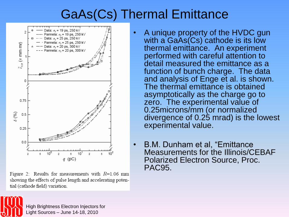
GaAs(Cs) Thermal Emittance
• A unique property of the HVDC gun with a GaAs(Cs) cathode is its low thermal emittance. An experiment performed with careful attention to detail measured the emittance as a function of bunch charge. The data and analysis of Enge et al. is shown. The thermal emittance is obtained asymptotically as the charge go to zero. The experimental value of 0.25microns/mm (or normalized divergence of 0.25 mrad) is the lowest experimental value.
• B.M. Dunham et al, “Emittance Measurements for the Illinois/CEBAF Polarized Electron Source, Proc. PAC95.
High Brightness Electron Injectors for
Light Sources – June 14-18, 2010
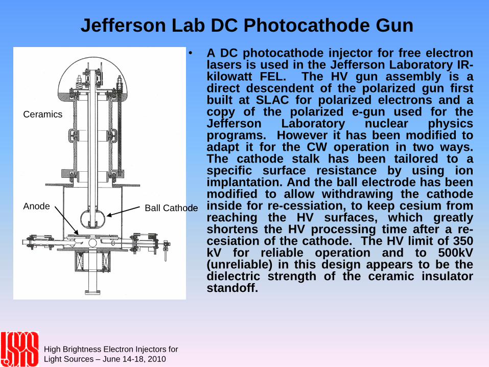
Jefferson Lab DC Photocathode Gun
• A DC photocathode injector for free electronlasers is used in the Jefferson Laboratory IR-kilowatt FEL. The HV gun assembly is adirect descendent of the polarized gun firstbuilt at SLAC for polarized electrons and acopy of the polarized e-gun used for theJefferson Laboratory nuclear physicsprograms. However it has been modified toadapt it for the CW operation in two ways.The cathode stalk has been tailored to aspecific surface resistance by using ionimplantation. And the ball electrode has beenmodified to allow withdrawing the cathodeinside for re-cessiation, to keep cesium fromreaching the HV surfaces, which greatlyshortens the HV processing time after a re-cesiation of the cathode. The HV limit of 350kV for reliable operation and to 500kV(unreliable) in this design appears to be thedielectric strength of the ceramic insulatorstandoff.
Ceramics
Ball CathodeAnode
Ceramics
Ball CathodeAnode
High Brightness Electron Injectors for
Light Sources – June 14-18, 2010
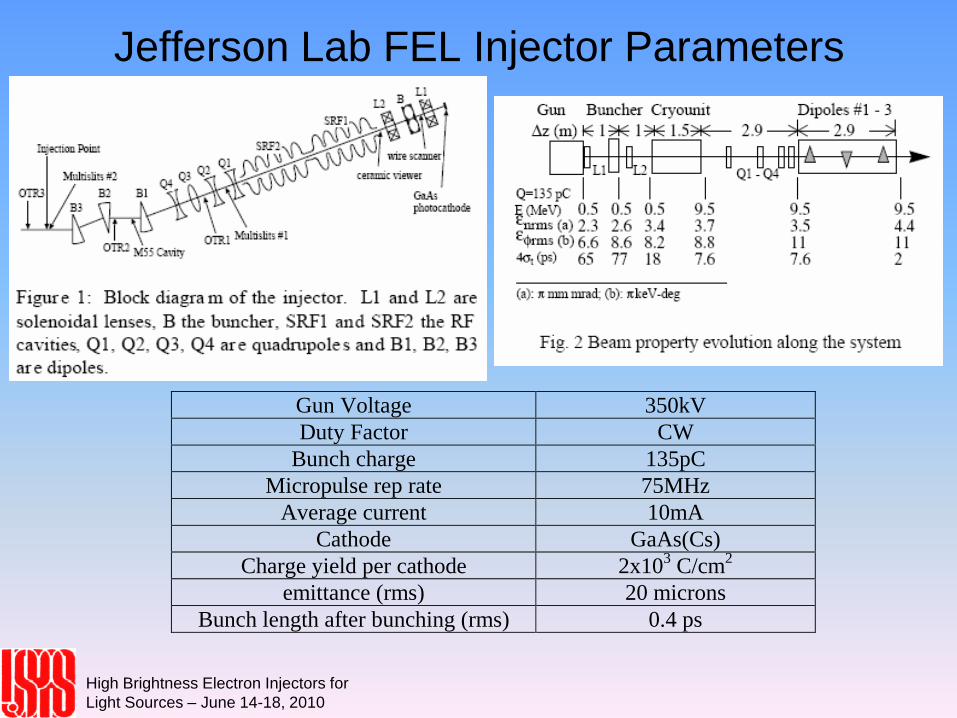
Jefferson Lab FEL Injector Parameters
Gun Voltage 350kV
Duty Factor CW
Bunch charge 135pC
Micropulse rep rate 75MHz
Average current 10mA
Cathode GaAs(Cs)
Charge yield per cathode 2x10³ C/cm
2
emittance (rms) 20 microns
Bunch length after bunching (rms) 0.4 ps
High Brightness Electron Injectors for
Light Sources – June 14-18, 2010
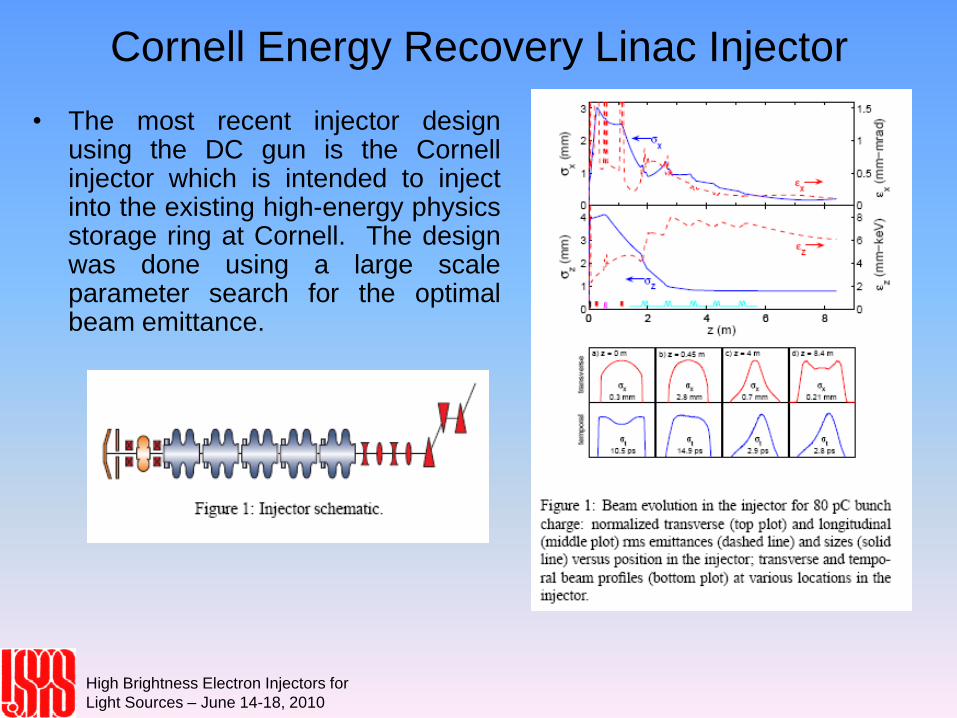
Cornell Energy Recovery Linac Injector
• The most recent injector designusing the DC gun is the Cornellinjector which is intended to injectinto the existing high-energy physicsstorage ring at Cornell. The designwas done using a large scaleparameter search for the optimalbeam emittance.
High Brightness Electron Injectors for
Light Sources – June 14-18, 2010
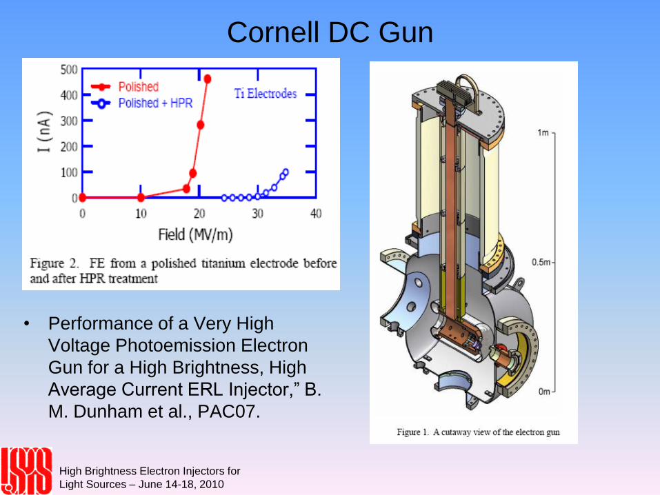
Cornell DC Gun
• Performance of a Very High
Voltage Photoemission Electron
Gun for a High Brightness, High
Average Current ERL Injector,” B.
M. Dunham et al., PAC07.
High Brightness Electron Injectors for
Light Sources – June 14-18, 2010
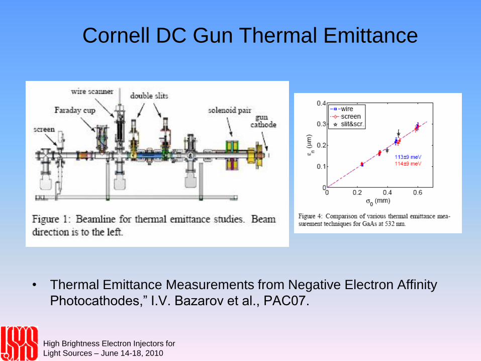
Cornell DC Gun Thermal Emittance
• Thermal Emittance Measurements from Negative Electron Affinity
Photocathodes,” I.V. Bazarov et al., PAC07.
High Brightness Electron Injectors for
Light Sources – June 14-18, 2010
Lecture 11
D.H. Dowell, S. Lidia, J.F. Schmerge
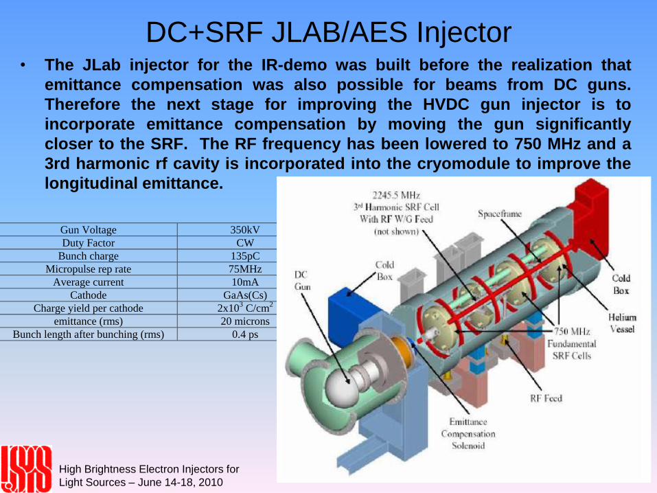
DC+SRF JLAB/AES Injector• The JLab injector for the IR-demo was built before the realization that
emittance compensation was also possible for beams from DC guns.
Therefore the next stage for improving the HVDC gun injector is to
incorporate emittance compensation by moving the gun significantly
closer to the SRF. The RF frequency has been lowered to 750 MHz and a
3rd harmonic rf cavity is incorporated into the cryomodule to improve the
longitudinal emittance.
Gun Voltage 350kV
Duty Factor CW
Bunch charge 135pC
Micropulse rep rate 75MHz
Average current 10mA
Cathode GaAs(Cs)
Charge yield per cathode 2x10³ C/cm
2
emittance (rms) 20 microns
Bunch length after bunching (rms) 0.4 ps
High Brightness Electron Injectors for
Light Sources – June 14-18, 2010
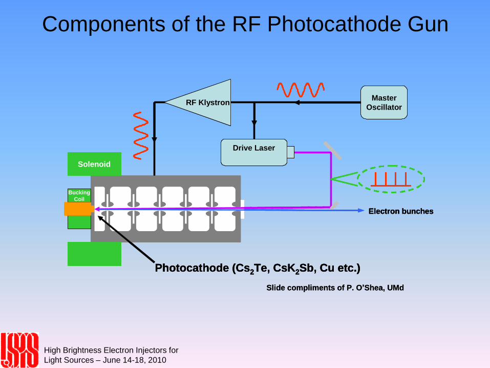
Components of the RF Photocathode Gun
Slide compliments of P. O’Shea, UMd
Solenoid
Master
Oscillator
Drive Laser
Bucking
Coil
Photocathode (Cs2Te, CsK2Sb, Cu etc.)
RF Klystron
Electron bunches
Slide compliments of P. O’Shea, UMd
Solenoid
Master
Oscillator
Drive Laser
Bucking
Coil
Photocathode (Cs2Te, CsK2Sb, Cu etc.)
RF Klystron
Electron bunches
Solenoid
Master
Oscillator
Drive LaserDrive Laser
Bucking
Coil
Photocathode (Cs2Te, CsK2Sb, Cu etc.)
RF Klystron
Electron bunches
High Brightness Electron Injectors for
Light Sources – June 14-18, 2010
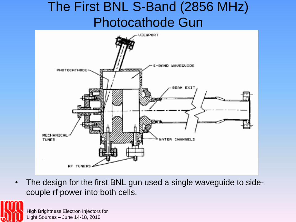
The First BNL S-Band (2856 MHz)
Photocathode Gun
• The design for the first BNL gun used a single waveguide to side-
couple rf power into both cells.
High Brightness Electron Injectors for
Light Sources – June 14-18, 2010
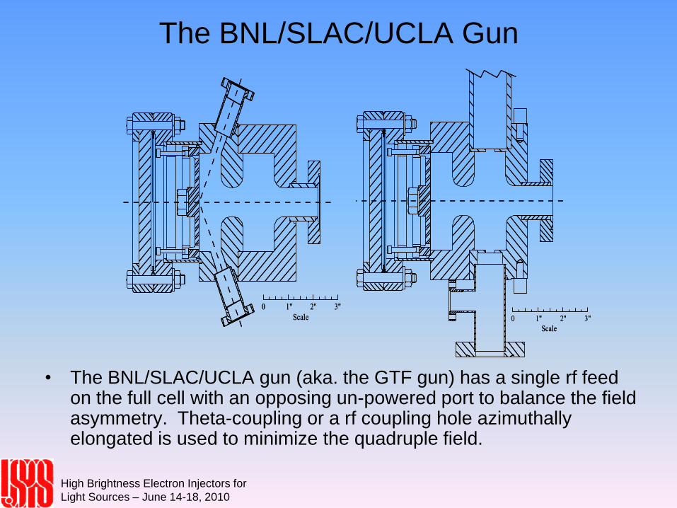
The BNL/SLAC/UCLA Gun
• The BNL/SLAC/UCLA gun (aka. the GTF gun) has a single rf feed on the full cell with an opposing un-powered port to balance the field asymmetry. Theta-coupling or a rf coupling hole azimuthally elongated is used to minimize the quadruple field.
Scale
2" 3"0 1"
Scale
2" 3"0 1"Scale
2" 3"0 1"
Scale
2" 3"0 1"
High Brightness Electron Injectors for
Light Sources – June 14-18, 2010
The LCLS S-Band Gun Design Features
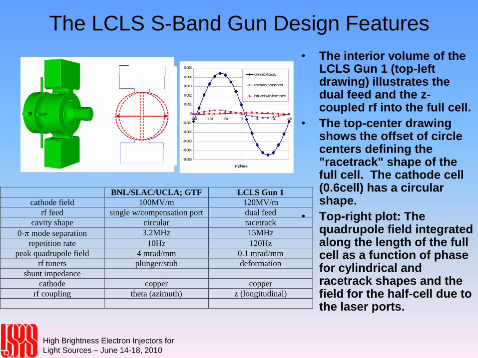
• The interior volume of the LCLS Gun 1 (top-left drawing) illustrates the dual feed and the z-coupled rf into the full cell.
• The top-center drawing shows the offset of circle centers defining the "racetrack" shape of the full cell. The cathode cell (0.6cell) has a circular shape.
• Top-right plot: The quadrupole field integrated along the length of the full cell as a function of phase for cylindrical and racetrack shapes and the field for the half-cell due to the laser ports.
-0.005
-0.004
-0.003
-0.002
-0.001
0
0.001
0.002
0.003
0.004
0.005
-180 -120 -60 0 60 120 180
rf phase
cylindrical cavity
racetrack coupler cell
half-cell with laser ports
BNL/SLAC/UCLA; GTF LCLS Gun 1
cathode field 100MV/m 120MV/m
rf feed single w/compensation port dual feed
cavity shape circular racetrack
0- mode separation 3.2MHz 15MHz
repetition rate 10Hz 120Hz
peak quadrupole field 4 mrad/mm 0.1 mrad/mm
rf tuners plunger/stub deformation
shunt impedance
cathode copper copper
rf coupling theta (azimuth) z (longitudinal)
High Brightness Electron Injectors for
Light Sources – June 14-18, 2010
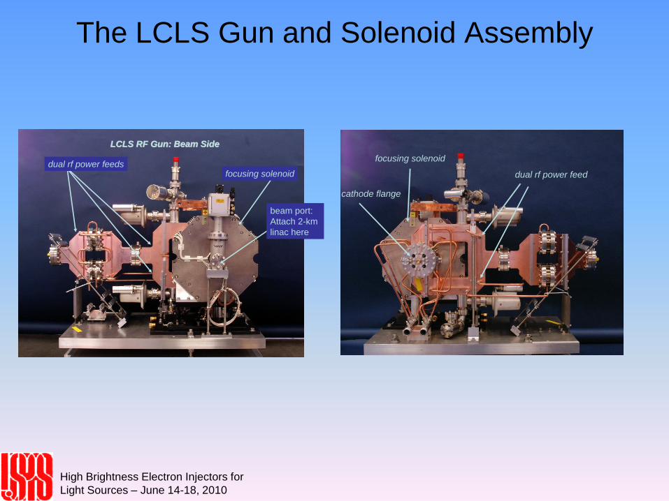
The LCLS Gun and Solenoid Assembly
cathode flange
dual rf power feed
focusing solenoid
cathode flange
dual rf power feed
focusing solenoid
LCLS RF Gun: Beam SideLCLS RF Gun: Beam Side
beam port:
Attach 2-km
linac here
focusing solenoiddual rf power feeds
LCLS RF Gun: Beam SideLCLS RF Gun: Beam Side
beam port:
Attach 2-km
linac here
focusing solenoiddual rf power feeds
High Brightness Electron Injectors for
Light Sources – June 14-18, 2010
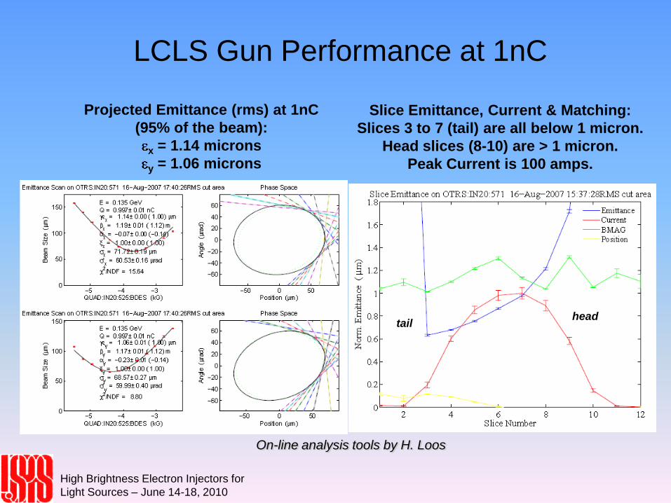
LCLS Gun Performance at 1nC
Projected Emittance (rms) at 1nC
(95% of the beam):
x = 1.14 microns
y = 1.06 microns
Slice Emittance, Current & Matching:
Slices 3 to 7 (tail) are all below 1 micron.
Head slices (8-10) are > 1 micron.
Peak Current is 100 amps.
tailhead
On-line analysis tools by H. Loos
High Brightness Electron Injectors for
Light Sources – June 14-18, 2010
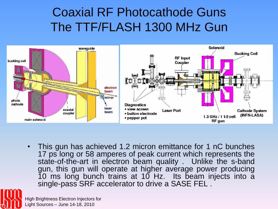
Coaxial RF Photocathode Guns
The TTF/FLASH 1300 MHz Gun
• This gun has achieved 1.2 micron emittance for 1 nC bunches17 ps long or 58 amperes of peak current which represents thestate-of-the-art in electron beam quality . Unlike the s-bandgun, this gun will operate at higher average power producing10 ms long bunch trains at 10 Hz. Its beam injects into asingle-pass SRF accelerator to drive a SASE FEL .
High Brightness Electron Injectors for
Light Sources – June 14-18, 2010
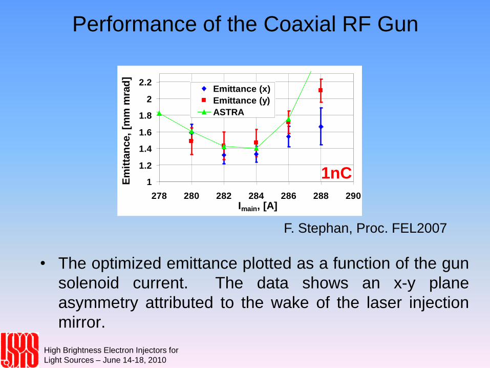
Performance of the Coaxial RF Gun
• The optimized emittance plotted as a function of the gun
solenoid current. The data shows an x-y plane
asymmetry attributed to the wake of the laser injection
mirror.
1
1.2
1.4
1.6
1.8
2
2.2
278 280 282 284 286 288 290Imain, [A]
Em
itta
nce,
[mm
mra
d]
Emittance (x)
Emittance (y)
ASTRA
1nC
F. Stephan, Proc. FEL2007
High Brightness Electron Injectors for
Light Sources – June 14-18, 2010
High-Average Power/Current Guns
• ERL based free electron lasers will require a continuous train ofelectron bunches to take full advantage of the ERL's capabilities. Ofcourse, the first ERL-based fel uses a DC gun which more easilylends itself to CW operation than the rf gun. However rf guns havedemonstrated higher single-bunch beam brightness than the DCguns, making it desirable to have a CW RF gun for this application.It is a major technical challenge to increase the rf gun duty factorfrom 0.01 percent to 100 percent, and currently there are twoapproaches being developed. The first maybe considered bruteforce as it 'simply' increases the rf power capability of the NormalConducting RF (NCRF) gun by lowering the frequency andimproving the cooling design. The second is to make the gun asuperconducting rf (SRF) gun. Given that ERL will already beoperating with a SRF accelerator system, the SRF gun naturally fitsinto the overall fel design, and once perfected is likely to become thechoice of future ERL-based fels.
High Brightness Electron Injectors for
Light Sources – June 14-18, 2010
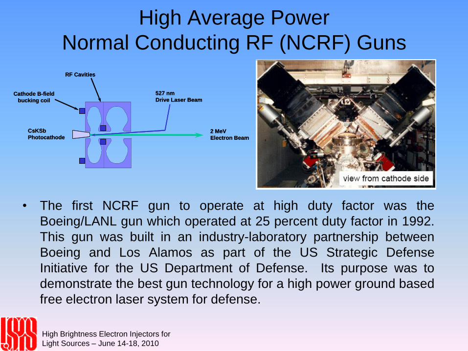
High Average Power
Normal Conducting RF (NCRF) Guns
• The first NCRF gun to operate at high duty factor was the
Boeing/LANL gun which operated at 25 percent duty factor in 1992.
This gun was built in an industry-laboratory partnership between
Boeing and Los Alamos as part of the US Strategic Defense
Initiative for the US Department of Defense. Its purpose was to
demonstrate the best gun technology for a high power ground based
free electron laser system for defense.
2 MeV
Electron Beam
527 nm
Drive Laser Beam
CsKSb
Photocathode
RF Cavities
Cathode B-field
bucking coil
2 MeV
Electron Beam
527 nm
Drive Laser Beam
CsKSb
Photocathode
RF Cavities
Cathode B-field
bucking coil
High Brightness Electron Injectors for
Light Sources – June 14-18, 2010
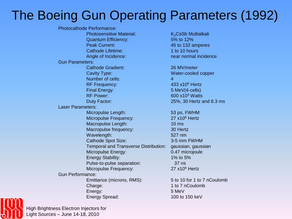
The Boeing Gun Operating Parameters (1992) Photocathode Performance:
Photosensitive Material: K2CsSb Multialkali
Quantum Efficiency: 5% to 12%
Peak Current: 45 to 132 amperes
Cathode Lifetime: 1 to 10 hours
Angle of Incidence: near normal incidence
Gun Parameters:
Cathode Gradient: 26 MV/meter
Cavity Type: Water-cooled copper
Number of cells: 4
RF Frequency: 433 x106 Hertz
Final Energy: 5 MeV(4-cells)
RF Power: 600 x103 Watts
Duty Factor: 25%, 30 Hertz and 8.3 ms
Laser Parameters:
Micropulse Length: 53 ps, FWHM
Micropulse Frequency: 27 x106 Hertz
Macropulse Length: 10 ms
Macropulse frequency: 30 Hertz
Wavelength: 527 nm
Cathode Spot Size: 3-5 mm FWHM
Temporal and Transverse Distribution: gaussian, gaussian
Micropulse Energy: 0.47 microjoule
Energy Stability: 1% to 5%
Pulse-to-pulse separation: 37 ns
Micropulse Frequency: 27 x106 Hertz
Gun Performance:
Emittance (microns, RMS): 5 to 10 for 1 to 7 nCoulomb
Charge: 1 to 7 nCoulomb
Energy: 5 MeV
Energy Spread: 100 to 150 keV
High Brightness Electron Injectors for
Light Sources – June 14-18, 2010
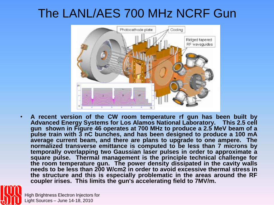
The LANL/AES 700 MHz NCRF Gun
• A recent version of the CW room temperature rf gun has been built byAdvanced Energy Systems for Los Alamos National Laboratory. This 2.5 cellgun shown in Figure 46 operates at 700 MHz to produce a 2.5 MeV beam of apulse train with 3 nC bunches, and has been designed to produce a 100 mAaverage current beam, and there are plans to upgrade to one ampere. Thenormalized transverse emittance is computed to be less than 7 microns bytemporally overlapping two Gaussian laser pulses in order to approximate asquare pulse. Thermal management is the principle technical challenge forthe room temperature gun. The power density dissipated in the cavity wallsneeds to be less than 200 W/cm2 in order to avoid excessive thermal stress inthe structure and this is especially problematic in the areas around the RFcoupler irises. This limits the gun's accelerating field to 7MV/m.
High Brightness Electron Injectors for
Light Sources – June 14-18, 2010
SRF Guns
• Since many of the proposed ERL-based FEL's will operate with SRF accelerators it is only natural to desire the gun to be SRF as well. The remote possibility of building such a gun became more immediate when the Rossendorf group in Dresden, Germany announced they had built and operated the world's first SRF gun . Although the bunch charge was less than 4 pC and the operating time was short, the achievement captured the RF gun community's imagination. As a result Rossendorf is now working on 3.5 cell version of their gun for their facility and is working with BESSY for a SRF gun as a source for a SASE fel proposed for that facility. A SRF gun is now being designed and built for an electron cooler system for RHIC at BNL.
• The major technical issues for the SRF gun are the thermal isolation between the cathode and the superconducting structure, and providing the focusing needed for emittance compensation. The first is important because the cathode is normal conducting, operating at 77degreesC. The isolation is performed by using an rf choke. And the superconducting structure cannot tolerate any magnetic field. The Rossendorf group has proposed providing this focusing with a variant of the two-frequency gun using a TE mode to provide magnetic rf focusing since magnetic focusing cannot be used in a SRF gun.
High Brightness Electron Injectors for
Light Sources – June 14-18, 2010
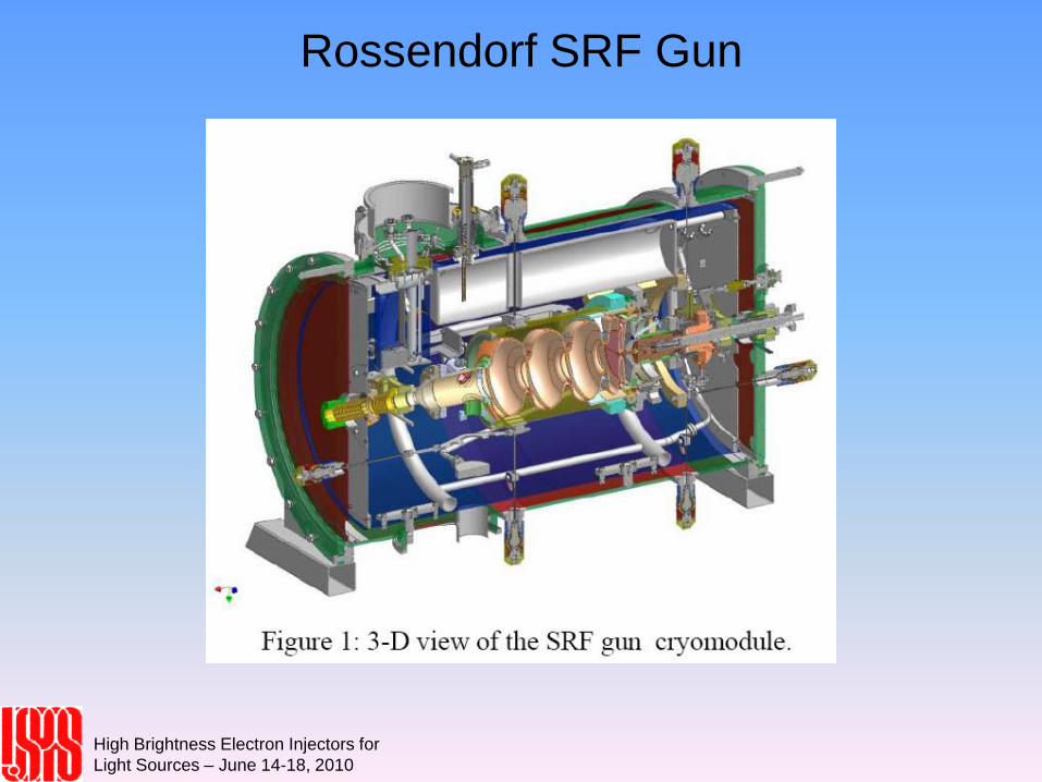
Rossendorf SRF Gun
High Brightness Electron Injectors for
Light Sources – June 14-18, 2010
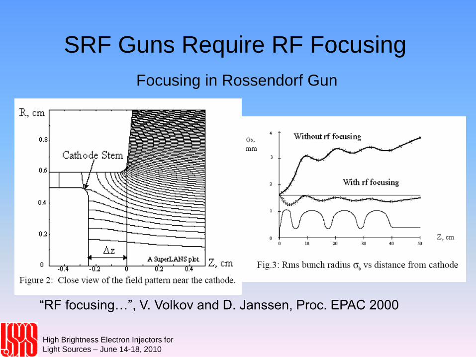
SRF Guns Require RF Focusing
Focusing in Rossendorf Gun
“RF focusing…”, V. Volkov and D. Janssen, Proc. EPAC 2000
High Brightness Electron Injectors for
Light Sources – June 14-18, 2010
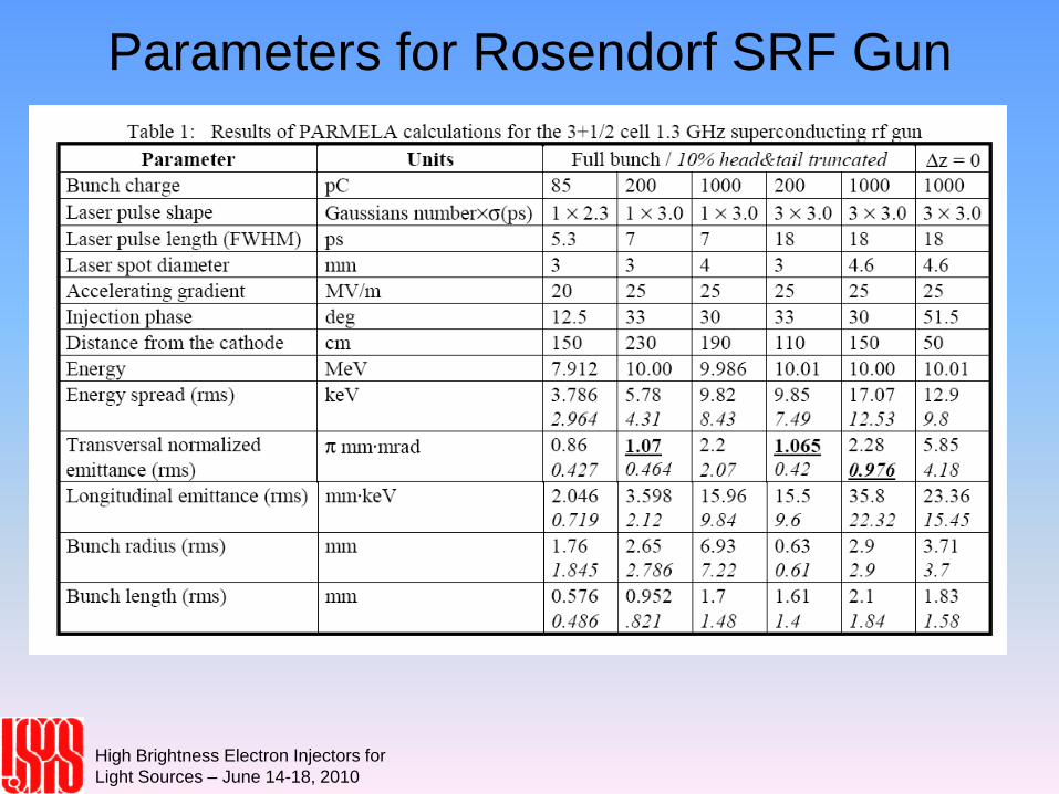
Parameters for Rosendorf SRF Gun
High Brightness Electron Injectors for
Light Sources – June 14-18, 2010
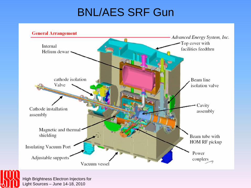
BNL/AES SRF Gun
High Brightness Electron Injectors for
Light Sources – June 14-18, 2010
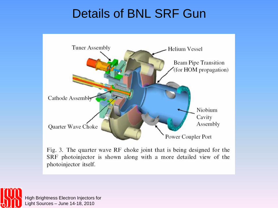
Details of BNL SRF Gun
High Brightness Electron Injectors for
Light Sources – June 14-18, 2010