Embed Size (px)
Citation preview

CLASSROOM STUDENT REFERENCE MATERIAL: GMAW Modes of Metal Transfer
CURRIC
ULU
MSAMPL
E

GMAW Modes of Metal Transfer
Objectives:
1. Identify the three basic forms of metal transfer used in gas metal arc welding (GMAW)
2. Compare and contrast the advantages and disadvantages of the 3 basic modes of metal transfer.
Terms:
defect: A discontinuity or discontinuities that by nature or accumulated effect (for example, total crack length) render a part or product unable to meet minimum applicable acceptance standards or specifications. This term designates rejectability. See also discontinuity and flaw.
discontinuity: An interruption of the typical structure of a weldment, such as a lack of homogeneity in the mechanical, metallurgical or physical characteristics of the material or weldment. A discontinuity is not necessarily a defect. See also defect and flaw.
globular transfer: A type of metal transfer in which the electrode produces a large ball of metal when it touches the workpiece. This deposits large amounts of metal into the weld puddle.
short circuit metal transfer: A type of metal transfer that occurs when the wire electrode touches the workpiece and produces a short circuit and high current. The high current level causes a violent transfer of metal, which creates the weld.
spray transfer: Metal transfer in which molten metal from a consumable electrode is propelled axially across the arc in small droplets.
11The Lincoln Electric CompanyCopyright © 2016, Lincoln Global.GMAW-MODESMETALTRANS: SR
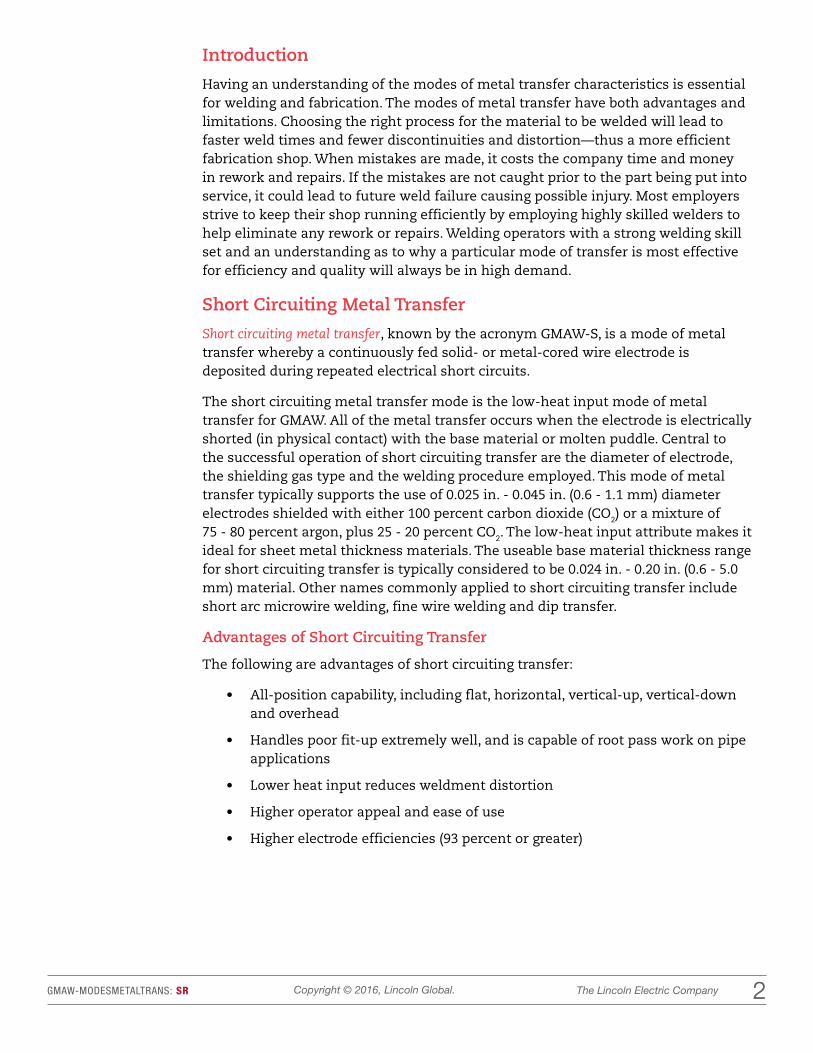
Introduction
Having an understanding of the modes of metal transfer characteristics is essential for welding and fabrication. The modes of metal transfer have both advantages and limitations. Choosing the right process for the material to be welded will lead to faster weld times and fewer discontinuities and distortion—thus a more efficient fabrication shop. When mistakes are made, it costs the company time and money in rework and repairs. If the mistakes are not caught prior to the part being put into service, it could lead to future weld failure causing possible injury. Most employers strive to keep their shop running efficiently by employing highly skilled welders to help eliminate any rework or repairs. Welding operators with a strong welding skill set and an understanding as to why a particular mode of transfer is most effective for efficiency and quality will always be in high demand.
Short Circuiting Metal Transfer
Short circuiting metal transfer, known by the acronym GMAW-S, is a mode of metal transfer whereby a continuously fed solid- or metal-cored wire electrode is deposited during repeated electrical short circuits.
The short circuiting metal transfer mode is the low-heat input mode of metal transfer for GMAW. All of the metal transfer occurs when the electrode is electrically shorted (in physical contact) with the base material or molten puddle. Central to the successful operation of short circuiting transfer are the diameter of electrode, the shielding gas type and the welding procedure employed. This mode of metal transfer typically supports the use of 0.025 in. - 0.045 in. (0.6 - 1.1 mm) diameter electrodes shielded with either 100 percent carbon dioxide (CO2) or a mixture of 75 - 80 percent argon, plus 25 - 20 percent CO2. The low-heat input attribute makes it ideal for sheet metal thickness materials. The useable base material thickness range for short circuiting transfer is typically considered to be 0.024 in. - 0.20 in. (0.6 - 5.0 mm) material. Other names commonly applied to short circuiting transfer include short arc microwire welding, fine wire welding and dip transfer.
Advantages of Short Circuiting Transfer
The following are advantages of short circuiting transfer:
• All-position capability, including flat, horizontal, vertical-up, vertical-down and overhead
• Handles poor fit-up extremely well, and is capable of root pass work on pipe applications
• Lower heat input reduces weldment distortion
• Higher operator appeal and ease of use
• Higher electrode efficiencies (93 percent or greater)
22The Lincoln Electric CompanyCopyright © 2016, Lincoln Global.GMAW-MODESMETALTRANS: SR

Limitations of Short Circuiting Transfer
The following are limitations of short circuiting transfer:
• Restricted to sheet metal thickness range and open roots of groove joints on heavier sections of base material
• Poor welding procedure control can result in incomplete fusion. Cold lap is another term that serves to describe an incomplete fusion defect
• Poor procedure control can result in excessive spatter and will increase weldment cleanup cost
• To prevent the loss of shielding gas to the wind, welding outdoors may require the use of a windscreen(s)
Description of Short Circuiting Transfer
The transfer of a single molten droplet of electrode occurs during the shorting phase of the transfer cycle. Please see Figure 1 below for an example of a short circuit metal transfer. Physical contact of the electrode occurs with the molten weld pool, and the number of short circuiting events can occur up to 200 times per second. The current delivered by the welding power supply rises, and the rise in current accompanies an increase in the magnetic force applied to the end of the electrode. The electromagnetic field, which surrounds the electrode, provides the force, which squeezes (more commonly known as “pinch”) the molten droplet from the end of the electrode.
Because of the low-heat input associated with short circuiting transfer, it is more commonly applied to sheet metal thickness material. However, it has frequently found use for welding the root pass in thicker sections of material in open-groove joints. The short circuiting mode lends itself to root pass applications on heavier plate-groove welds or pipe.
Figure 1. Short Circuiting Metal Transfer
33The Lincoln Electric CompanyCopyright © 2016, Lincoln Global.GMAW-MODESMETALTRANS: SR

Globular Transfer
Globular metal transfer is a GMAW mode of metal transfer whereby a continuously fed solid- or metal-cored wire electrode is deposited in a combination of short circuits and gravity-assisted large drops. The larger droplets are irregularly shaped.
During the use of all metal-cored or solid-wire electrodes for GMAW, there is a transition where short circuiting transfer ends and globular transfer begins (typically at 125 amps [A]). Globular transfer characteristically gives the appearance of large, irregularly shaped molten droplets that are larger than the diameter of the electrode. Please see Figure 2 below for globular metal transfer example. The irregularly shaped molten droplets do not follow an axial detachment from the electrode; instead, they can fall out of the path of the weld or move toward the contact tip. Cathode jet forces, which move upward from the workpiece, are responsible for the irregular shape and the upward-spinning motion of the molten droplets.
The process at this current level is difficult to control, and spatter is severe. Gravity is instrumental in the transfer of the large molten droplets, with occasional short circuits.
During the 1960s and 1970s, globular transfer was a popular mode of metal transfer for high- production sheet metal fabrication. The transfer mode is associated with the use of 100 percent CO2 shielding, but it has also seen heavy use with argon/CO2 blends. For general fabrication on carbon steel, it provides a mode of transfer just below the transition to axial spray transfer, which has lent itself to higher-speed welding.
The use of globular transfer in high-production settings is being replaced with advanced forms of GMAW. The change is being made to GMAW-P, which results in lower fume levels, lower or absent spatter levels, and elimination of incomplete fusion defects.
Figure 2. Globular Metal Transfer
44The Lincoln Electric CompanyCopyright © 2016, Lincoln Global.GMAW-MODESMETALTRANS: SR

Advantages of Globular Transfer
The following are advantages of globular transfer:
• Uses inexpensive CO2 shielding gas but is frequently used with argon/CO2 blends
• Capable of making welds at very high travel speeds
• Inexpensive solid- or metal-cored electrodes
• Welding equipment is inexpensive
Limitations of Globular Transfer:
The following are limitations of globular transfer:
• Higher spatter levels result in costly cleanup
• Reduced operator appeal
• Prone to cold lap incomplete fusion defects, which result in costly repairs
• Weld bead shape is convex and welds exhibit poor wetting at the toes
• High spatter level reduces electrode efficiency to a range of 87 - 93 percent
Axial Spray Transfer
Axial-spray metal transfer is the higher-energy mode of metal transfer whereby a continuously fed solid- or metal-cored wire electrode is deposited at a higher-energy level, resulting in a stream of small molten droplets. The droplets are propelled axially across the arc.
To achieve axial spray transfer, binary blends containing argon + 1-5 percent oxygen or argon + CO2, where the CO2 levels are 18 percent or less, are used . Axial spray transfer is supported by either the use of solid-wire or metal-cored electrodes. Axial spray transfer may be used with all of the common alloys including aluminum, magnesium, carbon steel, stainless steel, nickel alloys and copper alloys.
For most of the diameters of filler metal alloys, the change to axial spray transfer takes place at the globular to spray transition current. A stream of fine metal droplets that travels axially from the end of the electrode characterizes the axial-spray mode of metal transfer. The high-puddle fluidity restricts its use to the horizontal and flat welding positions.
For carbon steel, axial spray transfer is applied to heavier-section thickness material for fillets and for use in groove-type weld joints. The use of argon shielding gas compositions of 95 percent, with a balance of oxygen, creates a deep, finger-like penetration profile, while shielding gas mixes that contain more than 10 percent CO2 reduce the finger-like penetration profile and provide a more rounded type of penetration.
55The Lincoln Electric CompanyCopyright © 2016, Lincoln Global.GMAW-MODESMETALTRANS: SR

The selection of axial-spray metal transfer is dependent upon the thickness of base material and the ability to position the weld joint into the horizontal or flat welding positions. Finished weld bead appearance is excellent, and operator appeal is very high. Axial spray transfer provides its best results when the weld joint is free of oil, dirt, rust and mill scale. Please see Figure 3 below, which shows axial spray transfer.
Advantages of Axial Spray Transfer
The following are advantages of axial spray transfer:
• High deposition rates
• High electrode efficiency of 98 percent or more
• Employs a wide range of filler metal types in an equally wide range of electrode diameters
• Excellent weld bead appearance
• High operator appeal and ease of use
• Requires little post-weld cleanup
• Absence of weld spatter
• Excellent weld fusion
• Lends itself to semiautomatic, robotic and hard automation applications
Figure 3. Axial Spray Transfer
66The Lincoln Electric CompanyCopyright © 2016, Lincoln Global.GMAW-MODESMETALTRANS: SR

Limitations of Axial Spray Transfer
The following are limitations of axial spray transfer:
• Restricted to the flat and horizontal welding positions
• Welding fume generation is higher
• The higher-radiated heat and the generation of a very bright arc require extra welder and bystander protection
• The use of axial spray transfer outdoors requires the use of a windscreen(s)
• The shielding used to support axial spray transfer is more costly than 100% CO2
The welding industry is all about production, deposition rates, electrode efficiency and bottom line. Employers want their product manufactured as fast as possible with good penetration, appearance and no discontinuities. A lack of understanding on the part of the welding operator or weld engineer could lead to major repairs, discontinuities and defects. Having highly skilled employees who have an understanding of the relationship between amperage, voltage, wire feed speed (WFS), and contact tip to work distance (CTWD) within the different modes of metal transfer is vital to producing quality welds.
Conclusion
Since GMAW has a variety of metal transfer modes, welding professionals need to understand how each mode functions and must be able to correctly choose when to use a particular mode. The capabilities and limitations of each transfer mode require in-depth knowledge to use the appropriate option given the circumstances and goal at hand. By choosing the correct metal transfer mode, the welder can ensure the weld will be done properly and will be of high quality. The most effective and sought-after welders have a great understanding of each different transfer mode and can successfully choose the appropriate type based upon its advantages and limitations.
77The Lincoln Electric CompanyCopyright © 2016, Lincoln Global.GMAW-MODESMETALTRANS: SR

CLASSROOM LESSON PLAN: GMAW Modes of Metal Transfer
CURRIC
ULU
MSAMPL
E
11The Lincoln Electric CompanyCopyright © 2016, Lincoln Global.GMAW-MODESMETALTRANSFER: LP
GMAW Modes of Metal Transfer
Objective(s):
1. Identify the three basic forms of metal transfer used in gas metal arc welding (GMAW)
2. Compare and contrast the advantages and disadvantages of the 3 basic modes of metal transfer.
Course: GMAW
Resources:
Handouts
HO1: Know Your Role
HO2: Know Your Role Answers
AQ: GMAW Modes of Metal Transfer Assessment
Welding Lab Materials
VRTEX®
Reference Materials
LP1: GMAW Modes of Metal Transfer Lesson Plan
SR1: GMAW Modes of Metal Transfer Student Reference
PPT1: GMAW Modes of Metal Transfer
Terms:
defect: A discontinuity or discontinuities that by nature or accumulated effect (for example, total crack length) render a part or product unable to meet minimum applicable acceptance standards or specifications. This term designates rejectability. See also discontinuity and flaw.
discontinuity: An interruption of the typical structure of a weldment, such as a lack of homogeneity in the mechanical, metallurgical or physical characteristics of the material or weldment. A discontinuity is not necessarily a defect. See also defect and flaw.
globular transfer: A type of metal transfer in which the electrode produces a large ball of metal when it touches the workpiece. This deposits large amounts of metal into the weld puddle.
short circuit metal transfer: A type of metal transfer that occurs when the wire electrode touches the workpiece and produces a short circuit and high current. The high current level causes a violent transfer of metal, which creates the weld.
spray transfer: Metal transfer in which molten metal from a consumable electrode is propelled axially across the arc in small droplets.
Situation:
Prior to this lesson, students should have completed the Principles of Welding and Safety lessons.

22The Lincoln Electric CompanyCopyright © 2016, Lincoln Global.GMAW-MODESMETALTRANSFER: LP
Interest Approach (Motivation):
GMAW is widely used in the welding industry due to the high production rate it produces. The modes of transfer help control the heat input while maintaining the same high production high deposition rate. Your knowledge of these modes of transfer will be vital as you begin your career in the welding industry. You might start your first job welding on a particular type of material in a given welding position for a period of time; however, you never know where you will end up. Understanding the welding processes and how the arc transfers the filler material to the base metal will be extremely important. Welding is all about controlling the arc, heat input, and distortion by identifying the best mode of transfer and shielding gas. With technology changes comes a need for smarter welder/operators.
For example: If a piece of equipment is being manufactured and the customer would like to reduce the amount of passes and have the weld bead appear flat and smooth. The company has a positioner that can rotate the part. Using your knowledge of the modes of transfer, you suggest using GMAW-P for the following reasons:
Advantages:
1. GMAW–P can be used in out of position welding.
2. Eliminates incomplete fusion defects.
3. Reduces fume levels.
4. Reduces spatter.
5. Capable of travel speeds greater than 50 IPM.
6. Reduces level of heat induced distortion.
7. Handles poor fit up.
8. Saves time.
9. Eliminates the need for a weld positioner.
Limitations:
1. Welders will have to be qualified/certified in all positions in GMAW-P.
2. New, more expensive welder or module might need to be purchased for GMAW pulsed transfer.
3. Blend of gas is more expensive to operate.
Use the VRTEX to demonstrate the two modes of metal transfer that will be discussed in the class today.

33The Lincoln Electric CompanyCopyright © 2016, Lincoln Global.GMAW-MODESMETALTRANSFER: LP
Instructional Directions/Materials
Content Outline, Instructional Procedures and/or Key Questions
Recommend student-inquiry method of instruction, including guided discussion, readings, and demonstration-performance.
Use examples, real examples of welds, projects, tools, supplies.
Keep it simple. The best instructors are able to clearly describe processes using basic terms, simple explanations and lots of applied examples.
Begin every lesson with a short review of previous learning—daily reviews strengthen previous learning and lead to fluent recall.
PPT1: Modes of Metal Transfer Show slide #2: Review.
Use the lines below to list previous material for review.
•
•
•
•
•
PPT1: Modes of Metal Transfer Show slide #3.
Objectives:
1. Identify the three basic forms of metal transfer used in gas metal arc welding (GMAW)
2. Compare and contrast the advantages and disadvantages of the 3 basic modes of metal transfer.
PPT1: Modes of Metal Transfer Show slide #4.
Review materials from previous lesson.
What are the five variables associated with GMAW that will be associated with modes of metal transfer?
• Voltage
• Amperage
• Wire feed speed
• CTWD
• Shielding gas
All of these variables are linked together to affect quality and performance of the GMAW weld.

44The Lincoln Electric CompanyCopyright © 2016, Lincoln Global.GMAW-MODESMETALTRANSFER: LP
Instructional Directions/Materials
Content Outline, Instructional Procedures and/or Key Questions
Distribute HO1: Know Your Role. Have students fill in the blanks while the instructor discusses the material. (HO2: Know Your Role Answers may be used by the teacher to check responses or may be used for students who need more scaffolding.)
PPT1: Modes of Metal Transfer Show slide #5.
Use the VRTEX to demonstrate this mode of metal transfer.
Short Circuit Transfer
• Transfer of a single molten droplet of electrode
• Occurs up to 200 times per second
• The electromagnetic field that surrounds the electrode provides force that squeezes the molten droplet from the end of the electrode (pinch effect).
• Low heat input commonly applied to sheet metal thickness material
• Solid wire electrodes for short circuit transfer range from .020 to .045 diameter wire.
PPT1: Modes of Metal Transfer Show slide #6. Discuss with the students the advantages and limitations of the short circuit transfer mode.
Say, "The short circuit transfer mode is the foundation of many advanced GMAW processes."
Short circuit transfer is used to weld exhausts on cars.
Short circuit transfer is great for welding thin material.
Advantages
• All-position capability
• Lower heat input
• Higher operator appeal
• Higher electrode efficiencies
• Capability to perform root pass work on pipe
• Handles poor fit-up extremely well
Limitations
• Restricted to sheet metal thickness range and open roots of grooves on heavier sections of base material.
• Poor welding procedure control can result in incomplete fusion.
• Welding outdoors may require windscreens.
• Poor procedure control can result in excessive spatter, and will increase weldment cleanup costs.
1

55The Lincoln Electric CompanyCopyright © 2016, Lincoln Global.GMAW-MODESMETALTRANSFER: LP
Instructional Directions/Materials
Content Outline, Instructional Procedures and/or Key Questions
PPT1: Modes of Metal Transfer Show slide #7 and discuss the globular transfer mode.
Say, "The use of globular transfer is being replaced by advanced forms of GMAW. The GMAW-P mode of transfer is being used due to its lower fume levels, lower spatter levels, and elimination of incomplete fusion defects."
Globular Transfer Mode
• A continuously fed solid or metal cored wire electrode is deposited in a combination of short circuits and gravity-assisted large droplets
• Was popular mode of metal transfer for high production sheet metal fabrication during the 1960s and 1970s
• Associated with the use of 100% CO2 shielding
• For general fabrication on carbon steel, it provides a mode of transfer just below the axial spray mode with Argon/CO2 blends.
• Higher speed welding
PPT1: Modes of Metal Transfer Show slide #8 and discuss the advantages and limitations of the globular transfer mode.
Advantages
• Uses inexpensive CO2 shielding gas, but frequently used with argon/CO2
• Capable of making welds at very high speeds
• Uses inexpensive solid or metal cored electrodes
• Uses inexpensive welding equipment
Limitations
• Higher spatter levels result in costly clean up
• Cold lap incomplete fusion defects may result in costly repairs
• Weld bead shape is convex, and weld exhibits poor wetting at the toes
• Higher spatter levels reduces the electrode efficiency to a range of 87-93%
• Reduced operator appeal

66The Lincoln Electric CompanyCopyright © 2016, Lincoln Global.GMAW-MODESMETALTRANSFER: LP
Instructional Directions/Materials
Content Outline, Instructional Procedures and/or Key Questions
PPT1: Modes of Metal Transfer Show slide #9 and discuss the axial spray transfer mode.
Axial Spray Transfer Mode
• A higher energy mode of metal transfer
• A continuously fed solid or metal cored wire electrode is deposited at a higher energy level resulting in a stream of small molten droplets
PPT1: Modes of Metal Transfer Show slide #10 and discuss advantages and limitations.
Advantages
• High deposition rates
• High electrode efficiency
• Excellent bead appearance
• Little post weld clean up
• Excellent weld fusion
Limitations
• Flat and horizontal positions only
• High radiated heat
Formative Assessment
Teacher Tip: During the process, observe what information is being written. If students include incorrect information that has not been corrected, take time to review. Also, check that all the significant material about each topic was included.
Formative Assessment: Modes of Metal Transfer
1. Post chart paper in three locations around the room. Title each as follows: Short-Circuit Metal Transfer, Globular Transfer and Axial Spray Transfer.
2. Divide the class into three equal groups. Instruct each group to gather near one of the charts and provide each group a different color marker.
3. Give them a few minutes to write down all the information they can recall about that topic.
4. At the end of the five minutes, instruct them to move clockwise to the next chart and repeat the process. HOWEVER, they are not permitted to repeat any material already identified.
5. Additionally, if they notice incorrect information, they should take steps to correct it.
6. Repeat this process until each group has visited each chart.

77The Lincoln Electric CompanyCopyright © 2016, Lincoln Global.GMAW-MODESMETALTRANSFER: LP
Instructional Directions/Materials
Content Outline, Instructional Procedures and/or Key Questions
Application/Activity:
Mode of Transfer Lab:
• Students will weld using the different modes of transfer in order to understand the different arc characteristics associated with each mode.
• Students will record their data on a lab sheet that can be collected for a grade.
Supplemental Resources (Taking It Further)
Research:
• Why does 100% CO2 work in the short circuit transfer mode and not with axial spray or pulsed transfer modes?
• What shielding gas characteristics need to be in place in order to achieve axial spray and pulsed transfer?
Closure/Summary: Before assigning the quiz, have students take out a half sheet of paper. Tell them that you will answer any three questions about the material from this lesson – and they are free to write down the answers and use them on the quiz. Warn them, however, that they only get three questions, so they should choose wisely.
Evaluation/Assessment:
Hand out AQ1 and read over the directions with the students.
Assessment Key:
1. B–Globular
2. C–Axial spray
3. C–Axial spray
4. B–Globular
5. C–Axial spray
6. A–Short circuit
7. C–Axial spray
8. A–Short circuit
9. A–Short circuit
10. C–Axial spray
11. A–Short circuit
12. B–200
13. C–Cold lap
14. D–Pinch
88The Lincoln Electric CompanyCopyright © 2016, Lincoln Global.GMAW-MODESMETALTRANSFER: LP
Instructional Directions/Materials
Content Outline, Instructional Procedures and/or Key Questions
Assessment Key Cont'd.:
15. B–Globular
16. A–Short circuit
17. B–Globular
18. B–Cathode jet forces
19. C–Axial spray
20. B–Globular
21. A–Short circuit
22. C–Axial spray
23. B
24. C
25. A

STUDENT ASSESSMENT
CURRIC
ULU
MSAMPL
E

The Lincoln Electric CompanyCopyright © 2016, Lincoln Global.GMAW-MODESMETALTRANS: AQ 1
GMAW Modes of Metal Transfer Assessment
Name: Date:
Multiple Choice
Directions: Choose the letter of the best answer.
1. transfer is capable of very high travel speeds but has poor operator appeal.
A. Short circuit B. Globular
C. Axial spray D. None of the above
2. Which mode of transfer would be best for an application when where finished appearance is important?
A. Short circuit B. Globular
C. Axial spray D. None of the above
3. Which mode of metal transfer is considered to have the highest operator appeal?
A. Short circuit B. Globular
C. Axial spray D. None of the above
4. transfer is a GMAW mode of metal transfer whereby a continuously fed solid- or metal-cored wire electrode is deposited in a combination of short circuits and gravity-assisted large drops.
A. Short circuit B. Globular
C. Axial spray D. None of the above
5. metal transfer is the higher energy mode of transfer, resulting in a stream of small molten droplets.
A. Short circuit B. Globular
C. Axial spray D. None of the above
6. handles poor fit-up extremely well and is capable of root pass work on pipe.
A. Short circuit B. Axial spray
C. Globular D. None of the above
7. With transfer mode there is little post-weld clean up, excellent weld fusion and no weld spatter.
A. Short circuit B. Globular
C. Axial spray D. None of the above
The Lincoln Electric CompanyCopyright © 2016, Lincoln Global.GMAW-MODESMETALTRANS: AQ 2
GMAW Modes of Metal Transfer Assessment
Multiple Choice
Directions: Choose the letter of the best answer.
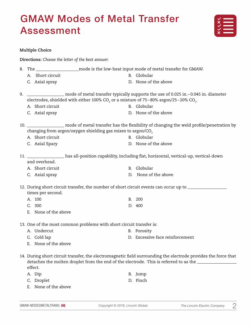
8. The mode is the low-heat input mode of metal transfer for GMAW.
A. Short circuit B. Globular
C. Axial spray D. None of the above
9. mode of metal transfer typically supports the use of 0.025 in. – 0.045 in. diameter electrodes, shielded with either 100% CO2 or a mixture of 75 – 80% argon/25 – 20% CO2.
A. Short circuit B. Globular
C. Axial spray D. None of the above
10. mode of metal transfer has the flexibility of changing the weld profile/penetration by changing from argon/oxygen shielding gas mixes to argon/CO2
A. Short circuit B. Globular
C. Axial Spary D. None of the above
11. has all-position capability, including flat, horizontal, vertical-up, vertical-down and overhead.
A. Short circuit B. Globular
C. Axial spray D. None of the above
12. During short circuit transfer, the number of short circuit events can occur up to times per second.
A. 100 B. 200
C. 300 D. 400
E. None of the above
13. One of the most common problems with short circuit transfer is:
A. Undercut B. Porosity
C. Cold lap D. Excessive face reinforcement
E. None of the above
14. During short circuit transfer, the electromagnetic field surrounding the electrode provides the force that detaches the molten droplet from the end of the electrode. This is referred to as the effect.
A. Dip B. Jump
C. Droplet D. Pinch
E. None of the above

The Lincoln Electric CompanyCopyright © 2016, Lincoln Global.GMAW-MODESMETALTRANS: AQ 3
GMAW Modes of Metal Transfer Assessment
Multiple Choice
Directions: Choose the letter of the best answer.
15. The mode of metal transfer typically begins at 125 amps.
A. Short circuit B. Globular
C. Axial spray D. None of the above
16. Sometimes referred to as dip transfer.
A. Short circuit B. Globular
C. Axial spray D. None of the above
17. transfer characteristically gives the appearance of large, irregularly shaped molten droplets that are larger than the diameter of the electrode.
A. Short circuit B. Globular
C. Axial spray D. None of the above
18. During globular transfer, , which move upward from the workpiece, are responsible for the irregular shape and the upward-spinning motion of the molten droplets.
A. Anode jet forces B. Cathode jet forces
C. Anode tube forces D. Cathode tube forces
E. Oscillation effect forces
19. transfer requires shielding gas blends containing argon/oxygen (1-5% O2) or argon/ CO2, where the CO2 levels are 18% or less.
A. Short circuit B. Globular
C. Axial spray D. None of the above
20. transfer has a weld bead shape that is convex and the welds exhibit poor wetting at the toes and higher spatter levels result in costly cleanup.
A. Short circuit B. Globular
C. Axial spray D. None of the above
21. The base metal thickness range for is typically considered 0.024 in. – 0.20 in. thick.
A. Short circuit B. Globular
C. Axial spray D. None of the above

The Lincoln Electric CompanyCopyright © 2016, Lincoln Global.GMAW-MODESMETALTRANS: AQ 4
GMAW Modes of Metal Transfer Assessment
Multiple Choice
Directions: Choose the letter of the best answer.
22. mode of metal transfer requires that the work be placed in the flat or horizontal welding positions.
A. Short circuit B. Globular
C. Axial spray D. None of the above
Matching
Directions: Match the mode of metal transfer with its illustration.
23. Globular
24. Short circuit
25. Axial spray
A
C
B

LESSON PLAN HANDOUTS: Know Your Role & Know Your Role Answers
CURRIC
ULU
MSAMPL
E

11The Lincoln Electric CompanyCopyright © 2016, Lincoln Global.GMAW-MODESMETALTRANSFER: HO1
Know Your RoleName: Date:
1
SHORT ARC GLOBULAR AXIAL SPRAYPULSED SPRAY
TRANSFER
Amperage range 30A - 200A 200A – 500A 200A – 500A
Voltage range 16V – 22V 24V – 35V
Wire diameter 0.035 and higher 0.035 and higher 0.035 and higher
Typical shielding gas 80% ↑ Ar and CO2 85% ↑ Ar and CO2
Material thickness 0.035” – 1/8” 0.125” – and higher 0.035” and higher
Spatter Slightly abundant None
Ease of use Easy Moderate Moderate to high
Cost Average High
Overall appearance Satisfactory Excellent
Welding positions Flat and horizontal All

11The Lincoln Electric CompanyCopyright © 2016, Lincoln Global.GMAW-MODESMETALTRANSFER: HO2
Know Your Role AnswersName: Date:
2
SHORT ARC GLOBULAR AXIAL SPRAYPULSED SPRAY
TRANSFER
Amperage range 30A - 200A 200A – 500A 200A – 500A 200A – 500A
Voltage range 16V – 22V 22V – 35V 24V – 35V 24V – 35V
Wire diameter 0.025 - 0.045 0.035 and higher 0.035 and higher 0.035 and higher
Typical shielding gas 100% CO2
100% CO2, 75% Ar/25% CO2
80% ↑ Ar and CO2 85% ↑ Ar and CO2
Material Thickness 0.035” – 1/8” 0.125” – and higher 0.125” and higher 0.035” and higher
Spatter Abundant Slightly abundant None None
Ease of Use Easy Moderate Moderate Moderate to high
Cost Low Average Average High
Overall Appearance Satisfactory Satisfactory Excellent Excellent
Welding Positions All Flat and horizontal Flat and horizontal All

CURRIC
ULU
M LAB ACTIVITY: GMAW Modes of Metal Transfer
SAMPL
E
11The Lincoln Electric CompanyCopyright © 2016, Lincoln Global.GMAW-MODESMETALTRANSFER: LA
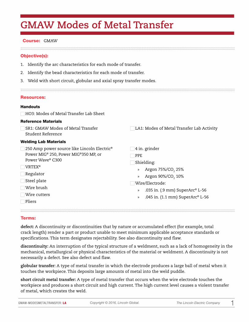
GMAW Modes of Metal TransferCourse: GMAW
Resources:
Handouts
HO3: Modes of Metal Transfer Lab Sheet
Reference Materials
SR1: GMAW Modes of Metal Transfer Student Reference
LA1: Modes of Metal Transfer Lab Activity
Welding Lab Materials
250 Amp power source like Lincoln Electric® Power MIG® 250, Power MIG®350 MP, or Power Wave® C300
VRTEX®
Regulator
Steel plate
Wire brush
Wire cutters
Pliers
4 in. grinder
PPE
Shielding:
» Argon 75%/CO2 25%
» Argon 90%/CO2 10%
Wire/Electrode:
» .035 in. (.9 mm) SuperArc® L-56
» .045 in. (1.1 mm) SuperArc® L-56
Objective(s):
1. Identify the arc characteristics for each mode of transfer.
2. Identify the bead characteristics for each mode of transfer.
3. Weld with short circuit, globular and axial spray transfer modes.
Terms:
defect: A discontinuity or discontinuities that by nature or accumulated effect (for example, total crack length) render a part or product unable to meet minimum applicable acceptance standards or specifications. This term designates rejectability. See also discontinuity and flaw.
discontinuity: An interruption of the typical structure of a weldment, such as a lack of homogeneity in the mechanical, metallurgical or physical characteristics of the material or weldment. A discontinuity is not necessarily a defect. See also defect and flaw.
globular transfer: A type of metal transfer in which the electrode produces a large ball of metal when it touches the workpiece. This deposits large amounts of metal into the weld puddle.
short circuit metal transfer: A type of metal transfer that occurs when the wire electrode touches the workpiece and produces a short circuit and high current. The high current level causes a violent transfer of metal, which creates the weld.

22The Lincoln Electric CompanyCopyright © 2016, Lincoln Global.GMAW-MODESMETALTRANSFER: LA
Situation:
Prior to this lab, students should have completed the GMAW Modes of Metal Transfer lesson.
Interest Approach (Motivation):
The welding industry is all about production, deposition rates, electrode efficiency and bottom line. Employers want their product manufactured as quickly as possible with good weld appearance and no discontinuities.
Terms Cont'd.:
spray transfer: Metal transfer in which molten metal from a consumable electrode is propelled axially across the arc in small droplets.

33The Lincoln Electric CompanyCopyright © 2016, Lincoln Global.GMAW-MODESMETALTRANSFER: LA
Instructional Directions/Teaching Tips/Materials
Content Outline, Instructional Procedures and/or Key Questions
Use the VRTEX to demonstrate to the students the short circuit transfer and axial spray transfer modes of metal transfer. Describe the following as you set up the machine:
• Machine settings
• Shielding gas
• All positions
• Unique characteristics
Review the modes of transfer with the students.
Be sure to point out proper welding techniques.
Optional:
Virtual Lab
Practice 1
Set the VRTEX 360 to WPS#2010114
• Short Circuit Transfer
» Description: Flat bead on plate (stringers)
» Wire/Electrode: .035 Super Arc® L–56
» Gas: 75% Argon/25% CO2 or 100% CO2
» Gas Flow: 25–35 CFH
» Plate Thickness: 1/4 in.
» IPM: 250
» Voltage: 18
» Polarity: DC+
» CTWD 3/8 in.
Set the VRTEX 360 to WPS#2010214
• Axial Spray Transfer
» Description: Flat bead on plate (stringers)
» Wire/Electrode: .045 Super Ar®c L–56
» Gas: 90% Argon/10% CO2
» Gas Flow: 25–40 CFH
» Plate Thickness: 1/4 in.
» IPM: 400
» Voltage: 27
» Polarity: DC+
» CTWD 1/2 in.

44The Lincoln Electric CompanyCopyright © 2016, Lincoln Global.GMAW-MODESMETALTRANSFER: LA
Instructional Directions/Teaching Tips/Materials
Content Outline, Instructional Procedures and/or Key Questions
Have the students practice welding on the VRTEX before moving into the live welding lab.
Prior to the students welding, the instructor should set up the booths for stations 1, 2 and 3. The students should not know which machine is set up for which mode of transfer. Students will decide which mode corresponds to which booth based on the arc characteristics, spatter level, bead shape and appearance.
• Station 2: Short Circuit Transfer
• Station 3: Globular Transfer
• Station 4: Axial Spray Transfer
Depending on class size, the number of booths to be set up will vary.
3Distribute HO3: Modes of Metal Transfer and explain how to record data.
Divide the students into groups of two or three.
Have students weld with each mode of transfer, recording their data on the lab worksheet
Live Welding Lab
Station 1
• Short Circuit Metal Transfer
» Description: Flat bead on plate (stringers)
» Wire/Electrode: .035 Super Arc® L-56
» Gas: 100% CO2
» Gas Flow: 30–50 CFH
» Plate Thickness: 1/4 in.
» IPM: 220–235
» Voltage: 18
» Polarity: DC+
» CTWD 3/8 in.

55The Lincoln Electric CompanyCopyright © 2016, Lincoln Global.GMAW-MODESMETALTRANSFER: LA
Instructional Directions/Teaching Tips/Materials
Content Outline, Instructional Procedures and/or Key Questions
Say, "To achieve this mode, the current must be between 125–150A. Make sure you are using the proper setting."
Station 2
• Globular Metal Transfer
» Description: Flat bead on plate (stringers)
» Wire/Electrode: .035
» Gas: 75%Argon/25%CO2
» Gas Flow: 25–35 CFH
» Plate Thickness: 1/4 in.
» IPM: 240–260
» Voltage: 20–22
» Polarity: DC+
» CTWD: 3/8 in.
Students will be challenged by this mode of metal transfer. They will have to adjust their CTWD to find the "sweet spot. "
Station 3
• Axial Spray Metal Transfer
» Description: Flat bead on plate (stringers)
» Wire/Electrode: .045 Super Arc® L-56
» Gas: 90% Argon/10% CO2
» Gas Flow: 25–40 CFH
» Plate Thickness: 1/4 in.
» IPM: 400
» Voltage: 26.5
» Polarity: DC+
» CTWD: 1/2 in.–5/8 in.
STEM Connection
Science:
Describe the relationship between the voltage, amperage, WFS and CTWD for the different modes of metal transfer.

66The Lincoln Electric CompanyCopyright © 2016, Lincoln Global.GMAW-MODESMETALTRANSFER: LA
Instructional Directions/Teaching Tips/Materials
Content Outline, Instructional Procedures and/or Key Questions
Closure/Summary: Knowing the characteristics of the different modes of metal transfer will be important as you begin to fabricate and build parts, machinery, and equipment. Employers not only need welders, they need highly skilled welders who know how the different materials will react to the modes of transfer.
Evaluation/Assessment:
1. The instructor will assess whether the student was able to weld in each of the modes of metal transfer.
2. The instructor will collect the lab sheets and evaluate the student’s observations.

LAB ACTIVITY HANDOUTS: Modes of Metal Transfer
CURRIC
ULU
MSAMPL
E

11The Lincoln Electric CompanyCopyright © 2016, Lincoln Global.GMAW-MODESMETALTRANSFER: HO3
Modes of Metal TransferName: Date:
In this lab, you will weld with three modes of metal transfer: short circuit, globular and axial spray. As you make a weld on a plate of mild steel, pay close attention to the arc and bead characteristics. Record these on the lab sheet.
3
Station 1:
1. Which mode of transfer is being performed in Station 1? (Circle)
Short Circuit Globular Axial Spray
2. Amount of spatter: None Slight Moderate Excessive
3. Bead shape: Convex Concave Flat
4. Describe some of the arc characteristics:
5. Describe the bead appearance:
6. What are typical applications for this mode of metal transfer?
Station 2:
1. Which mode of transfer is being performed in Station 2? (Circle)
Short Circuit Globular Axial Spray
2. Amount of spatter: None Slight Moderate Excessive
3. Bead shape: Convex Concave Flat
4. Describe some of the arc characteristics:
5. Describe the bead appearance:
6. What are typical applications for this mode of metal transfer?
22The Lincoln Electric CompanyCopyright © 2016, Lincoln Global.GMAW-MODESMETALTRANSFER: HO3
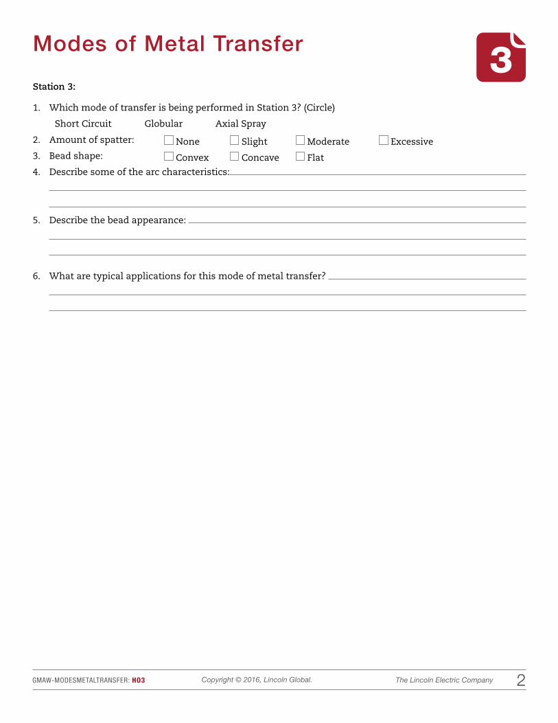
Modes of Metal Transfer 3Station 3:
1. Which mode of transfer is being performed in Station 3? (Circle)
Short Circuit Globular Axial Spray
2. Amount of spatter: None Slight Moderate Excessive
3. Bead shape: Convex Concave Flat
4. Describe some of the arc characteristics:
5. Describe the bead appearance:
6. What are typical applications for this mode of metal transfer?

WELD LESSON PLAN: Short Arc Flat Bead on Plate 1/4 in.
CURRIC
ULU
MSAMPL
E
1The Lincoln Electric CompanyCopyright © 2015, Lincoln Global.2010114-SAFLATBEAD1_4: LP
Short Arc Flat Bead on Plate 1/4 in.
Objective:
Perform a bead on plate on 1/4 in. (6.4 mm) mild steel using a GMAW short arc welding process to the standards described on the weld grading rubric provided.
MaterialsHandouts
WPS Sheet #2010114
HO1: Weld Inspection Checklist
HO2: Welding Lab Work
HO3: VRTEX® Lab Work
Weld Grading Rubric
Reference Materials
Short Arc Flat Bead on Plate 1/4 in. demo video
Lincoln Electric® GMAW Welding Guide (C4.200)
Lincoln Electric Welding Posters
Welding Lab Materials
1/4 inch (in.) (6.4 millimeter [mm]) mild steel plate welding coupons, 2 in. x 6 in. (50.8 mm x 152.4 mm) preferred
Constant voltage power source
Wire brushes
SuperArc® L-56 (ER70S-6); .035 in. (0.9 mm); 75/25
Vise grips
Flush nozzle
TermsARC CONTROL
CONTACT TO WORK DISTANCE
ELECTRICAL STICK OUT
CONTACT TIP
INDUCTANCE
NOZZLE
PINCH
WIRE FEED SPEED (WFS)
VOLTAGE
POLARITY
Situation
Prior to this lesson, students should have completed all safety lessons and successfully passed the welding safety exams.
Interest Approach (Motivation)
In this lesson students will learn how to successfully initiate the arc and run a stringer bead. Show the Short Arc Flat Bead on Plate 1/4 in. weld video. Mastering this skill will allow the student to successfully complete other welds more quickly.
Weld #: 2010114Level: Introductory Material: Mild Steel

2The Lincoln Electric CompanyCopyright © 2015, Lincoln Global.
Instructional Directions/Materials
Content Outline, Instructional Procedures and/or Key Questions
2010114-SAFLATBEAD1_4: LP
Hand out WPS sheet #2010114 and review the weld requirements.
It is not important to review all the specifications of the WPS at this time. Specifications will be highlighted as they are required by different welds.
Important weld requirements for a short arc flat bead on 1/4 in. (6.4 mm) mild steel plate:
1. Welding process
2. Type of welding process
3. Joint design used
4. Welding on both sides
5. Material thickness
6. Filler material requirement
7. Position
8. Polarity to be used
9. Power source type
10. Welding technique
11. Welding procedure
Before starting the weld, review how to set up and use the VRTEX machine.
1. Turning on the VRTEX
2. Setting the VRTEX
3. Selecting the variables (already set)
4. Performing a weld with the VRTEX
Demonstration steps:
1. Describe the weld that is going to be completed:
» Short arc flat bead on 1/4 in. (6.4 mm) mild steel using the short arc process.
2. Describe the proper techniques used to make a sound weld, including all of the following steps.
» Push travel angle: 10 – 15°
» Work angle: 90°
» Wire feed speed (WFS): 250±5 inches per minute (IPM) (6.3 meters per minute [m/min])
» Volts: 18±1 volts (V)
» Aim (will impact penetration in root)
» Stringer technique
Explain that students will use HO1: Weld Inspection Checklist to evaluate VRTEX weld.
If the students are familiar with the process of correctly configuring the VRTEX then it is best to have the VRTEX pre-configured for this section.
Ensure that the display screen is being viewed on a large screen in front of the class.
Use the INSTRUCTOR VIEW screen for the class.

3The Lincoln Electric CompanyCopyright © 2015, Lincoln Global.
Instructional Directions/Materials
Content Outline, Instructional Procedures and/or Key Questions
2010114-SAFLATBEAD1_4: LP
3. Turn on the replay function.
4. Place the welding helmet on your head and adjust lenses.
5. Make a weld.
6. While welding for the students, be sure to demonstrate the following:
» Weld 50% with good technique.
» Travel fast.
» Travel slowly.
» Use incorrect angles.
7. Inspect the weld with the class (compare it to posters).
8. Instruct the students to identify the good and bad elements of the weld.
9. Use the instant replay function to replay the weld being performed in front of the class.
10. Complete one weld using proper technique building a pad using the short arc process.
Setting up the demonstration
Connect VRTEX to screen so that all students can see teacher demonstrate the weld.
Demonstrate the travel angle, work angle, aim and electrode placement for the welder.
Padding is a common welding application. It is necessary to build up metal surfaces with one or more layers of weld deposit. Rebuilding a worn surface and repairing a machining error are two such applications. This work may be done on either flat or curved surfaces by depositing overlapping straight beads or weave passes.
Demonstrate first pass. Review first pass with students.
To help reinforce the previous topics, use the pause function. This will freeze the replay and give time to discuss that part of the weld.
Make sure that the students have a clear view of the weld you are making.
Important: All of the important welding variables for using the VRTEX are also important in welding using a real welder.
1. Place the welding helmet on your head.
2. Clean and prepare 1/4 in. (6.4 mm) mild sheet metal base material.
3. Set up the welding machine: DC+ polarity, gas 75/25, cubic feet per hour (CFH) 25-35 (12-16.5 liters per minute [l/min]), WFS 250±5 IPM (6.3 m/min), voltage 18±1 V, contact tip to work distance (CTWD) 3/8 in. (9.5 mm); increase by 2 V for CO2 gas.
For the live demo it is important to provide students plenty of visuals by using an electrode and tacked up weld joint.

4The Lincoln Electric CompanyCopyright © 2015, Lincoln Global.
Instructional Directions/Materials
Content Outline, Instructional Procedures and/or Key Questions
2010114-SAFLATBEAD1_4: LP
Make sure that all students have proper face shields and safety glasses for the demonstration.
Go over the power source/wire feeder. Show how to position head to maintain a good view of the puddle.
Describe pass 1.
Weld first pass.
4. Assume a position that permits you to see behind and ahead of the puddle so that corrections can be made while welding.
5. Check area for flammables and potential obstacles.
PASS 1: First pass
1. Describe the weld that is going to be completed:
» Short arc flat bead on 1/4 in. (6.4 mm) mild steel using the short arc process.
2. Describe the proper techniques used to make a sound weld:
» Push travel angle 10 – 15°
» Work angle 90°
» Aim (will impact penetration in root)
» Stringer bead
3. Place the welding helmet on your head.
4. Clean and prepare 1/4 in. (6.4 mm) mild sheet metal base material.
5. Set up the welding machine: DC+ polarity, Gas 75/25, CFH 25 – 35 (12-16.5 l/min.), WFS 250±5 IPM (6.3 m/min), voltage 18±1 V, CTWD 3/8 in. (9.5 mm); increase by 2 V for CO2 gas.
6. Position body so both the beginning and end of the weld can be reached comfortably.
7. Using a 90° work angle and a 10 – 15° push travel angle, make the first pass using a stringer technique. A slight oscillation can be used to smooth the bead out.
8. Clean the weld and visually inspect.

5The Lincoln Electric CompanyCopyright © 2015, Lincoln Global.
Instructional Directions/Materials
Content Outline, Instructional Procedures and/or Key Questions
2010114-SAFLATBEAD1_4: LP
9. While welding for students be sure to demonstrate the following:
» Weld 50% with good technique.
» Travel fast.
» Travel slowly.
» Use incorrect angles.
10. Inspect the weld with the class and look for uniformity and discontinuities.
11. Instruct students to identify the good and bad elements of the weld.
Evaluation
Guidelines below address common issues for students first attempting this weld:
1. Travel speed may be too high (ropy or string like bead).
2. Amperage may be too high (excessive spatter and wide flat bead).
3. Weld size may be inconsistent (a result of inconsistent speed)
4. WFS and voltage may be set incorrectly.
Be aware of common issues for students first attempting a short arc flat bead on 1/4 in. (6.4 mm) mild steel with a ER70S-6.
Instruct student to weld with opposite hand, making the pad as flat as possible. Make sure there are no crevices.

6The Lincoln Electric CompanyCopyright © 2015, Lincoln Global.
Instructional Directions/Materials
Content Outline, Instructional Procedures and/or Key Questions
2010114-SAFLATBEAD1_4: LP
Tolerance setting should be set to BEGINNER.
Use only ONE visual cue at a time to avoid overwhelming the student.
Depending on the number of VRTEX units available, the unit can be used in many ways to improve the students’ success on the building a pad using the short arc process.
1. To teach proper welding technique:
» Use visual cues (aim, travel speed, position, etc).
» Use replay mode and have students critique their welds.
2. Technique troubleshooting
» Have the student make a weld while watching the helmet cam on the monitor.
» Make sure that the students’ body position is not allowing the electrode clamp or other objects to block the view of the puddle.
» Use visual cues to aid in correcting technique problems.
3. Have students complete a series of welds on the VRTEX and save the LASER screen to the USB for later use.
» Use HO3: VRTEX Lab Work and have the students record their scores and reflect on how to better accomplish the weld.
Application
Closure/Summary
Evaluation
• Students building a pad using the short arc process
• Time welding with the VRTEX
Review technique and troubleshooting
Grade 5 welds using the appropriate weld grading rubric

The Lincoln Electric CompanyCopyright © 2015, Lincoln Global.2010114-SAFLATBEAD1_4: SR
Weld Inspection ChecklistName: Date:
Directions: Read the information below. Keep this handout for future reference.
Now that you have made some welds it is time to evaluate them. Evaluation of welds is a critical part of becoming a welder. Being able to distinguish between a good weld and a bad weld starts with a visual inspection. Visual inspections are fast and inexpensive. At a basic level, only good eyesight, good lighting and some welding knowledge are required.
WELD ID
FACE(fillet welds only) PLACEMENT UNIFORMITY UNDERCUT OVERLAP POROSITY
Points 2 1 2 1 1 2 1 2 1 2 Total
1 Concave Flat Convex Yes No Yes No Yes No Yes No Yes No
2 Concave Flat Convex Yes No Yes No Yes No Yes No Yes No
3 Concave Flat Convex Yes No Yes No Yes No Yes No Yes No
4 Concave Flat Convex Yes No Yes No Yes No Yes No Yes No
5 Concave Flat Convex Yes No Yes No Yes No Yes No Yes No
Table 1-1: Scoring a Weld
What to Do:
Perform a visual inspection on five welds that you have created in this activity by using the chart provided. Numerically identify your weld and follow the steps below.
STEP 1: For a fillet weld, the face of the weld might be flat, concave (sunken inward like a valley), or convex (shaped like a hill). A flat or slightly convex shape is preferred in most cases. Does the face of the weld you are inspecting have a concave, flat, or convex shape?
STEP 2: A good weld also is placed properly in the joint and should have the same amount of weld on both sides. Does your weld have good placement in the joint?
STEP 3: Welds that are the same size and shape from one end of the joint to the other are said to be uniform. Is your weld uniform from one end to the other?
STEP 4: Undercut at the toe can cause a weaker joint caused by improper machine settings and technique. Overlap can also weaken the joint by showing a lack of fusion. Can you see undercut and/or overlap in the weld that you are evaluating?
STEP 5: Porosity can be caused by dirty material or because the molten puddle was not shielded. Does the weld have any porosity?

The Lincoln Electric CompanyCopyright © 2015, Lincoln Global.2010114-SAFLATBEAD1_4: SR
Welding Lab WorkName: Date:
Directions: Follow the directions below to complete the welding lab work for this lesson.
Exercise A: Short Arc Flat Bead on Plate 1/4 in.
PASS 1
The travel angle should be 10 – 15°.
Work angle should be 90°.
1. Place the welding helmet on your head.
2. Clean and prepare 1/4 inch (in.) (6.4 millimeter [mm]) mild sheet metal base material.
3. Set up the welding machine:
» DC+ polarity
» Gas: 75/25
– Cubic feet per hour (CFH): 25 – 35 (12 – 16.5 liters per minute [l/min])
» Wire feed speed (WFS): 250±5 inches per minute (IPM) (6.3 meters per minute [m/min])
» Voltage: 18±1 volts (V)
– Increase by 2 V for CO2 gas
» Contact tip to work distance (CTWD): 3/8 in. (9.5 mm)
4. Position body so both the beginning and end of the weld can be reached comfortably.
5. Using a 90° work angle and a 10 – 15° push travel angle, make the first pass using a stringer technique. A slight oscillation can be used to smooth the bead out.
6. Clean and visually inspect the weld.
1

The Lincoln Electric CompanyCopyright © 2015, Lincoln Global.2010114-SAFLATBEAD1_4: SR
VRTEX® Lab WorkName: Date:
Directions: Follow the directions below to complete the VRTEX lab work for this lesson.
Exercise A: Weld a bead on plate on mild steel plate in the flat position with ER70S-6 in virtual reality.
Set up the VRTEX stand with the flat plate coupon in the flat position and adjust the arm and table so that you can comfortably use the VR welding gun on the coupon.
1. Make a practice weld to ensure that your body position allows you to weld comfortably from the beginning to the end of the weld.
2. Configure the VRTEX to weld a bead on mild steel in the flat position with a .035 in. (0.9 mm) ER70S-6 electrode.
3. Using NEXT
, change the image on the monitor to the LASER screen. If others are watching, you may want to use a different screen.
4. Use the welding technique described in the WELDING LAB WORK to completely weld this joint.
5. Select End Pass
to receive your scores for this weld.
6. Record the scores on this page and complete the reflection section.
7. Select New Coupon
to receive a new weld coupon.
8. If needed, select
Actions and Cues
to trim the wire.
9. Weld the joint again and record your performance from the LASER screen.
Record the scores from your first weld on the line to the right of to each category.
Position
CTWD
Work Angle
Travel Angle
Travel Speed
Reflection
Think of some changes you could make to improve your scores. List them below.
Make a second weld using the changes listed above. Record your scores below.
Position
CTWD
Work Angle
Travel Angle
Travel Speed
Compare the scores from your first weld to those from your second weld. Were the changes you made effective? Use the space below to explain.
3

The Lincoln Electric CompanyCopyright © 2015, Lincoln Global.
TO BE USED FOR TRAINING PURPOSES ONLY.
2010114-SAFLATBEAD1_4: LP
Welding Procedure Specification (WPS) Instructor's Key
SAMPLE
Company Name: Sample
Welding Process: GMAW
Type: Manual Semi-Automatic
Machine Automatic
Type: Lap Tee Butt
Corner Edge
Single Weld Double Weld
Backing: Yes No
Root Opening: N/A
Root Face Dimension: N/A
Groove Angle: N/A
Back Gouging: Yes No
Method: N/A
Transfer
Mode:
Short Circuit Globular
Spray Pulse
Other: N/A
Current: AC DCEP DCEN
Power Source: CC CV
Tungsten Electrode (GTAW):
Size: Type:
JOINT DESIGN USED POSITION
ELECTRICAL CHARACTERISTICS
TECHNIQUE
PREHEAT
BASE MATERIAL
FILLER METALS
SHIELDING
Material Spec: ASTMA A36
Type or Grade: N/A
Thickness: Groove: N/A Fillet: 10 GA (3.2 mm)
AWS Specification: A5.1
AWS Classification: ER70S-6 Size: XXX
Identification # Sample
Revision: Date: By
Authorized by: Date:
Supporting PQR No.(s)
Groove: N/A Fillet: 2F Flat Surfacing:
Vertical Progression: Up Down
Stringer, Weave Bead, Other: Stringer
Multi- or Single-Pass (per side): Single Pass
Number of Electrodes: Single
Contact Tip to Work Distance:
Peening: Yes No
Interpass Cleaning: Yes No
Cleaning Method: None
Preheat Temp: Min: N/A Max: N/A
Interpass Temp: Min: N/A Max: N/A
X
X
X
X
X
X
X
X
X
Electrode Flux (Class): N/A Gas: N/A
Composition: N/A
Flux: N/A Flow Rate:
Gas Cup Size:
WELDING PROCEDURE
Pass or Weld Layer(s) Technique
Filler Metals Current
Travel Speed Joint DetailsClass Diameter Type
& Polarity Amps (A)
1 Stringer ER70S-6 1/16" (1.6 mm) DC- 105±15
12
3
4
7
89
10
11
5
6

The Lincoln Electric CompanyCopyright © 2015, Lincoln Global.2010114-SAFLATBEAD1_4: SR
TO BE USED FOR TRAINING PURPOSES ONLY.
Welding Procedure Specification (WPS) Company Name:
Welding Process: GMAW
Type: Manual X Semi-Automatic
Machine Automatic
Type: Lap T Butt
Corner Edge
Single Weld Double Weld
Backing: Yes No
Root Opening: N/A
Root Face Dimension: N/A
Groove Angle:
Back Gouging: Yes No
Method: N/A
Transfer
Mode:
X Short Circuit Globular
Spray Pulse
Other: N/A
Current: AC DCEP DCEN
Power Source: CC X CV
Tungsten Electrode (GTAW):
Size: N/A Type: N/A
JOINT DESIGN USED POSITION
ELECTRICAL CHARACTERISTICS
TECHNIQUE
PREHEAT
BASE MATERIAL
FILLER METALS
SHIELDING
Material Spec: ASTM
Type or Grade: A36
Thickness: 1/4 in. (6.4 mm) Groove: N/A Fillet: N/A
AWS Specification: A5.18
AWS Classification: ER70S-6
Identification # 2010114
Revision: Date: By
Authorized by: Date:
Supporting PQR No.(s) LECO PQR 1
Groove: N/A Fillet: N/A Flat Surfacing: X
Vertical Progression: Up Down
Stringer, Weave Bead, Other: Stringer
Multi- or Single-Pass (per side): Single Pass
Number of Electrodes: Undefined
Contact Tip to Work Distance: 3/8 in. (9.5 mm)
Peening: Yes No
Interpass Cleaning: Yes No
Cleaning Method: Wire Brush
Preheat Temp: Min: Ambient Max: N/A
Interpass Temp: Min: N/A Max: N/A
X
XX
WELDING PROCEDURE
Pass or Weld Layer(s) Technique
Filler Metals CurrentVolts (V)/
Trim Travel Speed Joint DetailsClass Diameter Type
& PolarityWire Feed
Speed
1 Stringer ER70S-6 0.035 in (0.9 mm) DC+ 250±5 IPM (6.3 m/min) 18.0±1.0 15.0 IPM (0.38 m/min)
Electrode Flux (Class): N/A Gas: Argon/CO2
Composition: 75/25
Flux: N/A Flow Rate: 25-35 cfh (12-16.5 l/min)
Gas Cup Size: N/A
X
X
1