Embed Size (px)
Citation preview
SAFE PRACTICES FOR THE PRODUCTION OF
NITROUS OXIDE FROM AMMONIUM NITRATE
AIGA 080/16
Revision of AIGA 080/13
Asia Industrial Gases Association
3 HarbourFront Place, #09-04 HarbourFront Tower 2, Singapore 099254 Tel : +65 62760160 Fax : +65 62749379
Internet : http://www.asiaiga.org
Reproduced with permission from the Compressed Gas Association. All rights reserved.
ASIA INDUSTRIAL GASES ASSOCIATION 3 HarbourFront Place, #09-04 HarbourFront Tower 2, Singapore 099254
Tel: +65 62760160 Fax: +65 62749379 Internet: http://www.asiaiga.org
AIGA 080/16
SAFE PRACTICES FOR THE PRODUCTION OF NITROUS OXIDE
FROM AMMONIUM NITRATE
As part of a programme of harmonization of industry standards, the Asia Industrial Gases Association (AIGA) has issued this publication 080, Safe Practices for the Production of Nitrous Oxide from Ammonium Nitrate, jointly produced by members of the International Harmonisation Council and originally published by the European Industrial Gases Association (EIGA), Safe Practices for the Production of Nitrous Oxide from Ammonium Nitrate. This publication is intended as an international harmonized publication for the worldwide use and application by all members of Asia Industrial Gases Association (AIGA), Compressed Gas Association (CGA), EIGA, and Japan Industrial and Medical Gases Association (JIMGA). Each association’s technical content is identical, except for regional regulatory requirements and minor changes in formatting and spelling.
Disclaimer
All publications of AIGA or bearing AIGA’s name contain information, including Codes of Practice, safety procedures and other technical information that were obtained from sources believed by AIGA to be reliable and/ or based on technical information and experience currently available from members of AIGA and others at the date of the publication. As such, we do not make any representation or warranty nor accept any liability as to the accuracy, completeness or correctness of the information contained in these publications. While AIGA recommends that its members refer to or use its publications, such reference to or use thereof by its members or third parties is purely voluntary and not binding. AIGA or its members make no guarantee of the results and assume no liability or responsibility in connection with the reference to or use of information or suggestions contained in AIGA’s publications. AIGA has no control whatsoever as regards, performance or non performance, misinterpretation, proper or improper use of any information or suggestions contained in AIGA’s publications by any person or entity (including AIGA members) and AIGA expressly disclaims any liability in connection thereto. AIGA’s publications are subject to periodic review and users are cautioned to obtain the latest edition.
AIGA AIGA 080/16
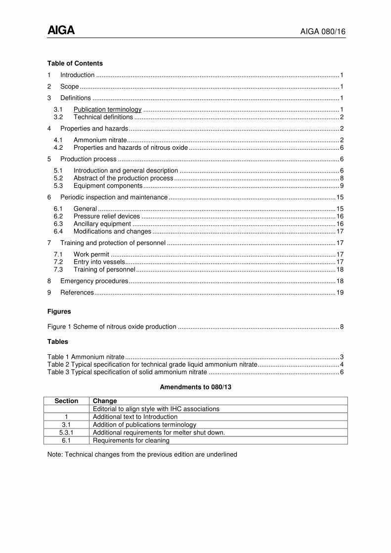
Table of Contents
1 Introduction ...................................................................................................................................... 1
2 Scope ............................................................................................................................................... 1
3 Definitions ........................................................................................................................................ 1
3.1 Publication terminology ............................................................................................................ 1
3.2 Technical definitions ................................................................................................................. 2
4 Properties and hazards .................................................................................................................... 2
4.1 Ammonium nitrate ..................................................................................................................... 2
4.2 Properties and hazards of nitrous oxide ................................................................................... 6
5 Production process .......................................................................................................................... 6
5.1 Introduction and general description ........................................................................................ 6
5.2 Abstract of the production process ........................................................................................... 8
5.3 Equipment components ............................................................................................................ 9
6 Periodic inspection and maintenance ............................................................................................ 15
6.1 General ................................................................................................................................... 15
6.2 Pressure relief devices ........................................................................................................... 16
6.3 Ancillary equipment ................................................................................................................ 16
6.4 Modifications and changes ..................................................................................................... 17
7 Training and protection of personnel ............................................................................................. 17
7.1 Work permit ............................................................................................................................ 17
7.2 Entry into vessels .................................................................................................................... 17
7.3 Training of personnel .............................................................................................................. 18
8 Emergency procedures .................................................................................................................. 18
9 References ..................................................................................................................................... 19
Figures Figure 1 Scheme of nitrous oxide production ......................................................................................... 8
Tables Table 1 Ammonium nitrate ...................................................................................................................... 3
Table 2 Typical specification for technical grade liquid ammonium nitrate ............................................. 4
Table 3 Typical specification of solid ammonium nitrate ........................................................................ 6
Amendments to 080/13
Section Change
Editorial to align style with IHC associations
1 Additional text to Introduction
3.1 Addition of publications terminology
5.3.1 Additional requirements for melter shut down.
6.1 Requirements for cleaning
Note: Technical changes from the previous edition are underlined
AIGA AIGA 080/16
1
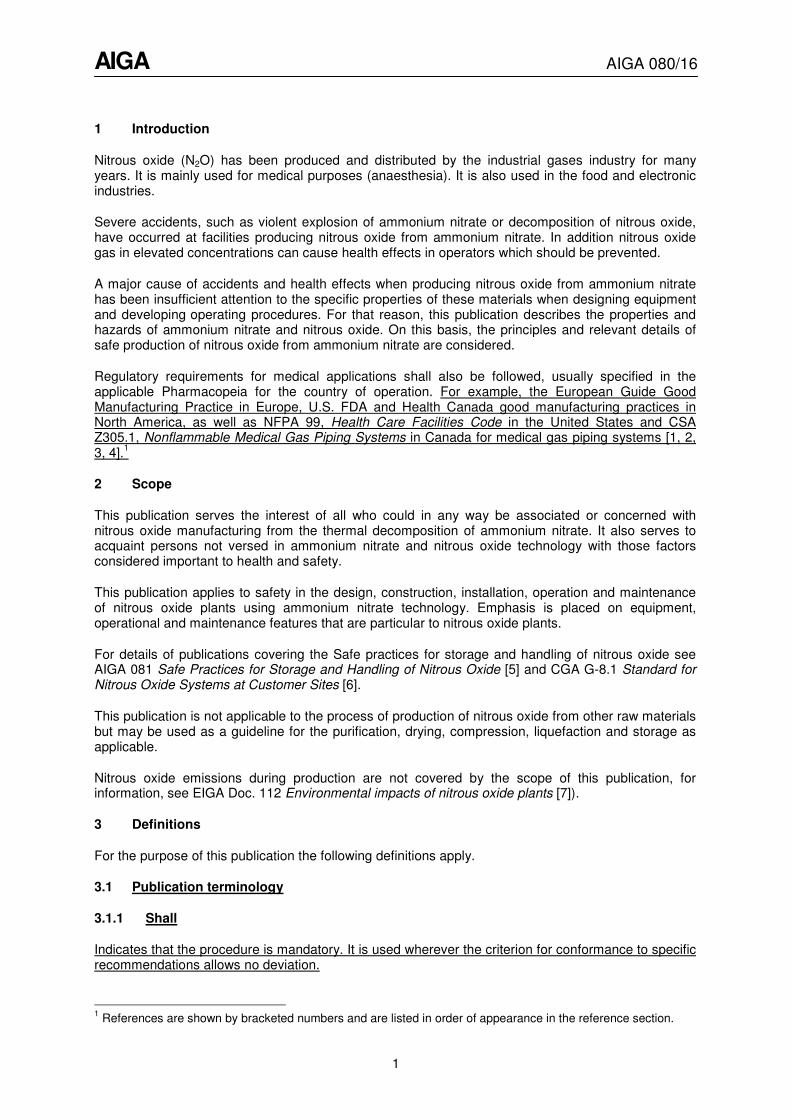
1 Introduction
Nitrous oxide (N2O) has been produced and distributed by the industrial gases industry for many years. It is mainly used for medical purposes (anaesthesia). It is also used in the food and electronic industries.
Severe accidents, such as violent explosion of ammonium nitrate or decomposition of nitrous oxide, have occurred at facilities producing nitrous oxide from ammonium nitrate. In addition nitrous oxide gas in elevated concentrations can cause health effects in operators which should be prevented.
A major cause of accidents and health effects when producing nitrous oxide from ammonium nitrate has been insufficient attention to the specific properties of these materials when designing equipment and developing operating procedures. For that reason, this publication describes the properties and hazards of ammonium nitrate and nitrous oxide. On this basis, the principles and relevant details of safe production of nitrous oxide from ammonium nitrate are considered.
Regulatory requirements for medical applications shall also be followed, usually specified in the applicable Pharmacopeia for the country of operation. For example, the European Guide Good Manufacturing Practice in Europe, U.S. FDA and Health Canada good manufacturing practices in North America, as well as NFPA 99, Health Care Facilities Code in the United States and CSA Z305.1, Nonflammable Medical Gas Piping Systems in Canada for medical gas piping systems [1, 2, 3, 4].
1
2 Scope
This publication serves the interest of all who could in any way be associated or concerned with nitrous oxide manufacturing from the thermal decomposition of ammonium nitrate. It also serves to acquaint persons not versed in ammonium nitrate and nitrous oxide technology with those factors considered important to health and safety.
This publication applies to safety in the design, construction, installation, operation and maintenance of nitrous oxide plants using ammonium nitrate technology. Emphasis is placed on equipment, operational and maintenance features that are particular to nitrous oxide plants.
For details of publications covering the Safe practices for storage and handling of nitrous oxide see AIGA 081 Safe Practices for Storage and Handling of Nitrous Oxide [5] and CGA G-8.1 Standard for Nitrous Oxide Systems at Customer Sites [6].
This publication is not applicable to the process of production of nitrous oxide from other raw materials but may be used as a guideline for the purification, drying, compression, liquefaction and storage as applicable.
Nitrous oxide emissions during production are not covered by the scope of this publication, for information, see EIGA Doc. 112 Environmental impacts of nitrous oxide plants [7]).
3 Definitions
For the purpose of this publication the following definitions apply.
3.1 Publication terminology
3.1.1 Shall
Indicates that the procedure is mandatory. It is used wherever the criterion for conformance to specific recommendations allows no deviation.
1 References are shown by bracketed numbers and are listed in order of appearance in the reference section.
AIGA AIGA 080/16
2
3.1.2 Should
Indicates that a procedure is recommended.
3.1.3 May
Indicates that the procedure is optional.
3.1.4 Will
Is used only to indicate the future, not a degree of requirement.
3.1.5 Can
Indicates a possibility or ability.
3.2 Technical definitions
3.2.1 Cylinder
Transportable pressure receptacle of a water capacity not exceeding 150 litres [8].
3.2.2 Decomposition
Separation of a chemical compound into smaller elements.
NOTE Ammonium nitrate and nitrous oxide separates into components in an exothermic reaction that can be accelerated by changes in pressure, temperature, energy inputs, the presence of catalyser or impurities.
3.2.3 Liquefied gas
Gas which when packaged under pressure for carriage is partially liquid at temperatures above – 50 °C [8].
3.2.4 Qualified nitrous oxide technician
Person who by reason of education, training and experience is knowledgeable of the properties of nitrous oxide, is familiar with the equipment used to store, transfer, and use nitrous oxide and understands the precautions necessary to safely use nitrous oxide equipment.
3.2.5 Pressure
In this publication “bar“(“psi”) shall indicate gauge pressure unless otherwise noted, for example “bar abs“(“psia”) for absolute pressure and “bar dif“ (“psid”) for differential pressure.
3.2.6 Tank
Collective term that includes stationary tanks and transport tanks.
4 Properties and hazards
4.1 Ammonium nitrate
Both forms of the feedstock, solid ammonium nitrate (SAN) and liquid ammonium nitrate (LAN) shall be considered as oxidizing substances with relevant properties and requiring safety precautions see Table 1.
AIGA AIGA 080/16
3
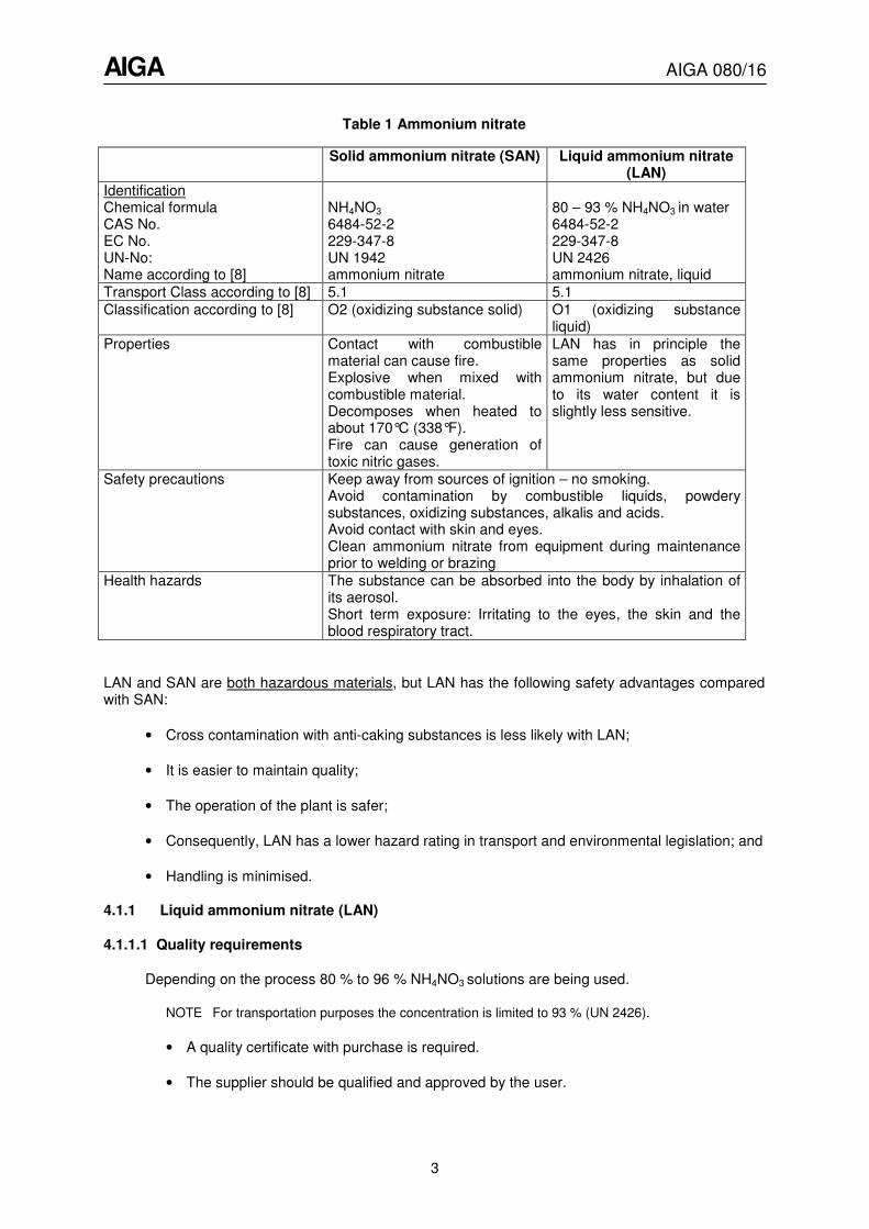
Table 1 Ammonium nitrate
Solid ammonium nitrate (SAN) Liquid ammonium nitrate (LAN)
Identification Chemical formula CAS No. EC No. UN-No: Name according to [8]
NH4NO3
6484-52-2 229-347-8 UN 1942 ammonium nitrate
80 – 93 % NH4NO3 in water 6484-52-2 229-347-8 UN 2426 ammonium nitrate, liquid
Transport Class according to [8] 5.1 5.1
Classification according to [8] O2 (oxidizing substance solid) O1 (oxidizing substance liquid)
Properties Contact with combustible material can cause fire. Explosive when mixed with combustible material. Decomposes when heated to about 170°C (338°F). Fire can cause generation of toxic nitric gases.
LAN has in principle the same properties as solid ammonium nitrate, but due to its water content it is slightly less sensitive.
Safety precautions Keep away from sources of ignition – no smoking. Avoid contamination by combustible liquids, powdery substances, oxidizing substances, alkalis and acids. Avoid contact with skin and eyes. Clean ammonium nitrate from equipment during maintenance prior to welding or brazing
Health hazards The substance can be absorbed into the body by inhalation of its aerosol. Short term exposure: Irritating to the eyes, the skin and the blood respiratory tract.
LAN and SAN are both hazardous materials, but LAN has the following safety advantages compared with SAN:
• Cross contamination with anti-caking substances is less likely with LAN;
• It is easier to maintain quality;
• The operation of the plant is safer;
• Consequently, LAN has a lower hazard rating in transport and environmental legislation; and
• Handling is minimised.
4.1.1 Liquid ammonium nitrate (LAN)
4.1.1.1 Quality requirements
Depending on the process 80 % to 96 % NH4NO3 solutions are being used.
NOTE For transportation purposes the concentration is limited to 93 % (UN 2426).
• A quality certificate with purchase is required.
• The supplier should be qualified and approved by the user.
AIGA AIGA 080/16
4
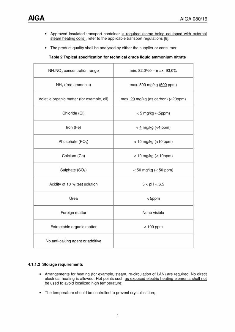
• Approved insulated transport container is required (some being equipped with external steam heating coils), refer to the applicable transport regulations [8].
• The product quality shall be analysed by either the supplier or consumer.
Table 2 Typical specification for technical grade liquid ammonium nitrate
NH4NO3 concentration range min. 82.0%0 – max. 93,0%
NH3 (free ammonia) max. 500 mg/kg (500 ppm)
Volatile organic matter (for example, oil) max. 20 mg/kg (as carbon) (<20ppm)
Chloride (Cl) < 5 mg/kg (<5ppm)
Iron (Fe) < 4 mg/kg (<4 ppm)
Phosphate (PO4) < 10 mg/kg (<10 ppm)
Calcium (Ca) < 10 mg/kg (< 10ppm)
Sulphate (SO4) < 50 mg/kg (< 50 ppm)
Acidity of 10 % test solution 5 < pH < 6.5
Urea < 5ppm
Foreign matter None visible
Extractable organic matter < 100 ppm
No anti-caking agent or additive
4.1.1.2 Storage requirements
• Arrangements for heating (for example, steam, re-circulation of LAN) are required. No direct electrical heating is allowed. Hot points such as exposed electric heating elements shall not be used to avoid localized high temperature;
• The temperature should be controlled to prevent crystallisation;
AIGA AIGA 080/16
5
• If necessary the actual ammonium nitrate concentration should be controlled and diluted to the required specification. Additional water should have low chloride and iron content;
• Storage quantity shall be according to local regulations;
• The LAN storage tank area shall be protected against spillage and the tank discharge system shall be protected to prevent inadvertent discharge into drains, for example, by a retention area;
• The LAN unloading system, including the transfer system, needs to be cleaned thoroughly to avoid any SAN build-up; good practice is to use water of low chloride content; and
• If possible LAN should be transferred from the trailer to the tank by pressurization and to the nitrous oxide plant by gravity. Pumping LAN requires a specific pump design to avoid dry running.
4.1.2 Solid ammonium nitrate (SAN)
4.1.2.1 General requirements
• Depending on local regulations approval could be required for purchase, transport and storage due to the fact that explosives can be produced from SAN; and
• Safety distances to public roads and residential areas shall comply with local regulations.
4.1.2.2 Quality requirements
• A quality certificate with purchase is required; and
• The supplier should be qualified and approved by the user.
4.1.2.3 Typical specification
AIGA AIGA 080/16
6
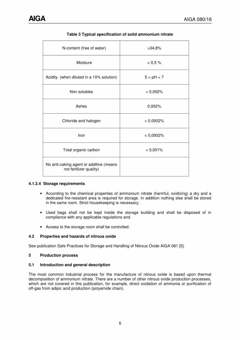
Table 3 Typical specification of solid ammonium nitrate
N-content (free of water) >34,8%
Moisture < 0,5 %
Acidity (when diluted in a 10% solution) 5 < pH < 7
Non solubles < 0,002%
Ashes 0,002%
Chloride and halogen < 0,0002%
Iron < 0,0002%
Total organic carbon < 0,001%
No anti-caking agent or additive (means not fertilizer quality)
4.1.2.4 Storage requirements
• According to the chemical properties of ammonium nitrate (harmful, oxidizing) a dry and a dedicated fire-resistant area is required for storage. In addition nothing else shall be stored in the same room. Strict housekeeping is necessary;
• Used bags shall not be kept inside the storage building and shall be disposed of in compliance with any applicable regulations and.
• Access to the storage room shall be controlled.
4.2 Properties and hazards of nitrous oxide
See publication Safe Practices for Storage and Handling of Nitrous Oxide AIGA 081 [5].
5 Production process
5.1 Introduction and general description
The most common industrial process for the manufacture of nitrous oxide is based upon thermal decomposition of ammonium nitrate. There are a number of other nitrous oxide production processes, which are not covered in this publication, for example, direct oxidation of ammonia or purification of off-gas from adipic acid production (polyamide chain).
AIGA AIGA 080/16
7
5.1.1 Chemical background of the thermal decomposition process
Nitrous oxide is produced by thermally decomposing a hot solution of ammonium nitrate and water at concentrations varying from 80% to 93% at a temperature of approximately 250°C to 255°C, (482°F to 491°F). Thermal decomposition of ammonium nitrate is complex and can follow different routes.
The main and desired reaction is:
NH4NO3 � N2O +2H2O
This reaction is exothermic, generating 59 kJ / mole at approximately 250°C,(482°F) and it is a first order reaction with an estimated energy of activation of 150 kJ / mole - 200 kJ / mole at standard conditions (273 K, 1013 mbar).
The reaction kinetics of decomposition doubles for every 10°C (18°F) incremental increase in temperature (or the rate of decomposition multiplies by a factor of 1.07 for each °C. As an order of magnitude, a mass of molten ammonium nitrate producing 200 kg/h of nitrous oxide in a reactor at 250°C (482°F) develops a thermal power of about 70 kW; at 255 °C (491°F) the same reactor would produce 280 kg/h (40% more), with a heat production of 98 kW.
A variety of reactions take place in an ammonium nitrate reactor being operated to produce nitrous
oxide. The pure ammonium nitrate salt melts at 169°C (337°F), and begins decomposing at 190°C
(375° F). At temperatures up to 250°C (482°F), two reactions predominate and are of primary interest
to the production of nitrous oxide by thermal decomposition of ammonium nitrate.
Decomposition:
NH4NO3 � N2O + 2H2O ▲H = -59 KJ/g-mol (-315 BTU/lb)
Dissociation:
NH4NO3 � NH3 + HNO3 ▲H = +159.9 KJ/g-mol (+860 BTU/lb)
NOTE The decomposition reaction is exothermic and the dissociation reaction is endothermic.
The decomposition reaction is the desired reaction, producing nitrous oxide. The dissociation reaction
becomes appreciable at 210°C (410°F) and continues to become more predominant with increasing
temperature. Increasing pressure suppresses the dissociation reaction. If adequate venting is provided for the reactor, in the event of loss of control of the reactor, with rapidly rising temperature, the dissociation reaction eventually checks the temperature rise as it is capable of absorbing the heat generated by all of the other exothermic reactions combined. If adequate venting is not provided, pressure rise suppresses dissociation and the pressure and temperature will continue to rise until the ammonium nitrate is consumed or there is an explosion.
5.1.1.1 Side reactions
In addition to the primary reactions discussed above, minor side reactions take place producing nitrogen and the higher nitrogen oxides.
The unit operations required to remove the minor components produced by these reactions are discussed below.
5.1.1.2 Chloride catalyzed decomposition
The decomposition of ammonium nitrate in the melted phase will be faster and can occur at temperatures below the melting point when the ammonium nitrate contains chloride components or when the added water contains chloride ions. The reactions in presence of chloride components
AIGA AIGA 080/16
8
produce principally nitrogen. Steel components exposed to chlorides in the presence of high moisture and/or high temperatures can result in chloride stress corrosion cracking.
Other components have a similar catalytic effect, see AIGA 081 [5].
5.1.1.3 Corrosion – Use of stabilizers
Ammonium nitrate solution is very corrosive to several metals, including copper, brass, zinc and carbon steel. Even stainless steel after prolonged periods of contact undergoes limited attack, which transfers ferric ions into the solution. Addition of small quantities of di-ammonium phosphate ((NH4)2HPO4) or ammonium dihydrogen phosphate ((NH4H2PO4) also known as mono-ammonium phosphate), or phosphoric acid (H3PO4) in ammonium nitrate limits this reaction.
Where the purity of ammonium nitrate or water quality could lead to corrosion in the melter or reactor, phosphoric acid is often used to prevent corrosion.
5.1.1.4 Contamination
Accidental contamination of ammonium nitrate by combustible materials for example, oil shall be avoided by taking appropriate measures.
Ammonium nitrate shall be controlled thoroughly (see 4.1). Traces of anticaking substances from cross contamination with fertilizer grade ammonium nitrate will make the reaction violent and produce high amounts of carbon monoxide, carbon dioxide, and nitrogen,. Therefore quality control of raw ammonium nitrate is required.
5.2 Abstract of the production process
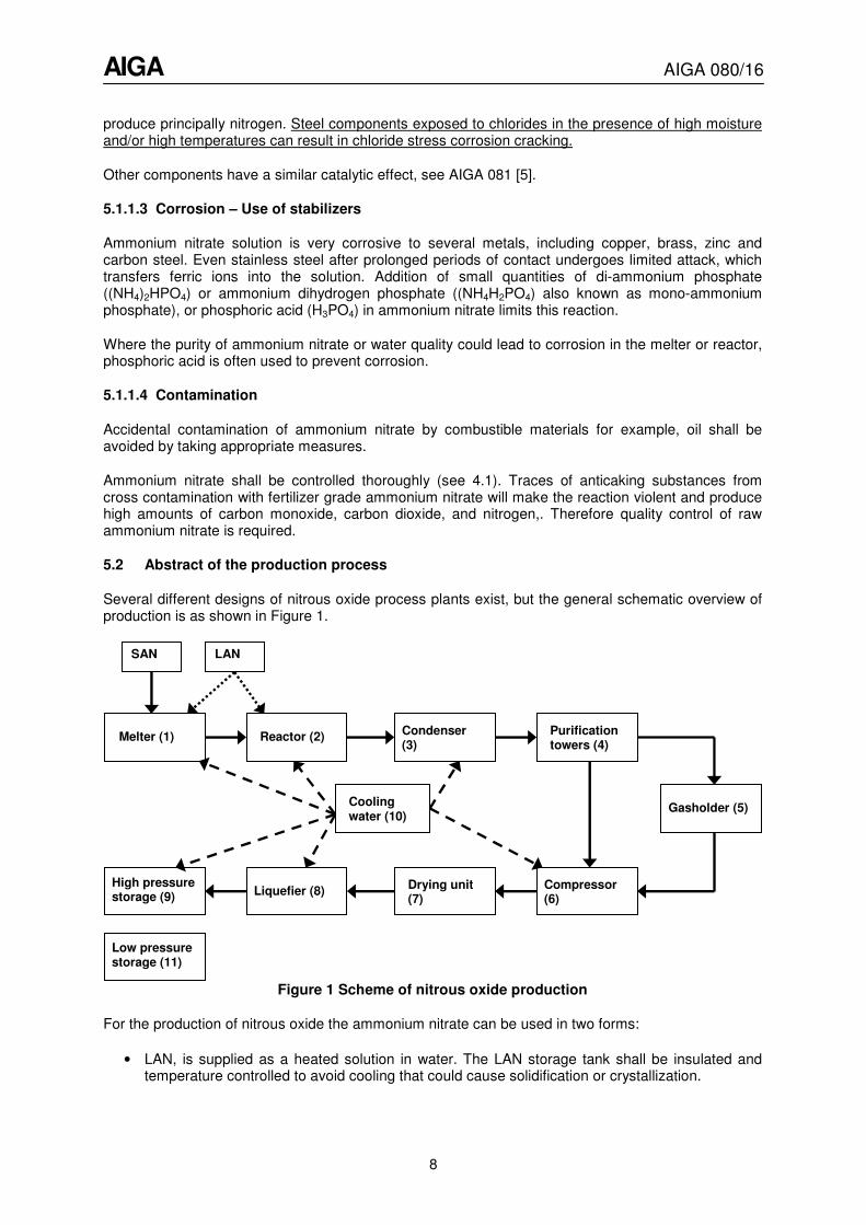
Several different designs of nitrous oxide process plants exist, but the general schematic overview of production is as shown in Figure 1.
Figure 1 Scheme of nitrous oxide production
For the production of nitrous oxide the ammonium nitrate can be used in two forms:
• LAN, is supplied as a heated solution in water. The LAN storage tank shall be insulated and temperature controlled to avoid cooling that could cause solidification or crystallization.
Reactor (2)
SAN LAN
Condenser (3)
Melter (1)
Gasholder (5)
Purification towers (4)
Drying unit (7)
Cooling water (10)
Compressor (6)
Liquefier (8)
Low pressure storage (11)
High pressure storage (9)
AIGA AIGA 080/16
9
• SAN is added to a melter where water is added to form a liquid solution. This is an additional processing step ahead of the LAN process listed above. (It has been reported that some solid feed plants melt and decompose SAN without any addition of water; this technology is not recommended and not covered by this publication).
Solid storage and a melter (1) are required for solid feed plants. Liquid hot solution tanks are required for liquid feed plants. In both cases, technical grade of ammonium nitrate, with low amounts of chloride and metals, is required. The liquid is injected into the reactor (2). Here the LAN undergoes a thermal decomposition into nitrous oxide and water vapour.
Control of the reaction is achieved by maintaining the mass and thermal balances by monitoring and adjusting the flow rate of ammonium nitrate and / or the heating power.
Other control parameters are:
• LAN level in the reactor;
• temperature of the LAN;
• pressure control in the gas phase; and
• gas flow rate exiting the reactor.
The temperature of the LAN is then maintained by heating and cooling the reactor.
The heat produced by the reaction may be used for preheating the LAN in the melter or the LAN before entering the reactor.
The produced gas is cooled and the water vapour is condensed in a counter-current water cooled condenser (3). The gas stream passes next through a number of chemical purification steps using towers (4). Impurities such as nitrogen oxides, (NOx), nitric acid, (HNO3), and ammonia, (NH3) are washed out in a sequence of absorption towers employing water, a mixture of potassium permanganate and sodium hydroxide, sulphuric acid and finally water. Some plants operate without the sulphuric acid purification step.
The purified nitrous oxide can be accumulated in a gasholder (5), depending upon the plant design. This accumulation device acts as a compensator for variations in production. The gas is compressed to liquefaction pressure (6) and, after drying (7), it is liquefied (8) with cooling water (10) or other non-flammable refrigerant. The product is then stored (9, 11) and ready for further purification, filling cylinders or for bulk transport.
5.3 Equipment components
5.3.1 Melter
The following applies to plants using SAN.
The SAN is melted by addition of approximately 8% water and by heating up to a temperature of
125°C to 130°C (257°F to 266°F). Addition of di-ammonium phosphate or ammonium dihydrogen
phosphate (also known as mono-ammonium phosphate) is made to the stabilize reaction (see also 6.1).
The melter is divided into two sections:
• Melting or consumption section. For LAN this section can be used for preheating.
• Transfer section from which the LAN is fed to the reactor.
AIGA AIGA 080/16
10
Each section is heated independently.
Passage of LAN from dilution to transfer section can be achieved by hydrostatic pressure or pneumatic pumps.
Melter requirements:
• Ensure the dilution section is at ambient temperature before introducing the ammonium nitrate and always introduce the water first, never introduce SAN into an empty and hot melter;
• Ensure a high / low level control either by procedure or automatically;
• Heating systems shall be such that there is no contact between the heating source and the LAN.
• Provide a system for re-circulating / homogenizing the solution during the heating and melting process, to make sure there is no hotter point than the measured temperature;
• Equip the melter with temperature control (T = 125°C - 130°C (257°F - 266°F)) in production mode). The temperatures of the consumption section and the transfer section shall each be controlled by two independent temperature control systems.
• Heat the injection line (pipe connection between melter and reactor) to avoid re-crystallization;
• Limit the melter temperature to 130°C (266°F) during non-production periods and 140°C (284°F) during production;
• For the preparation of the aqueous solution the water shall have low chloride and iron content (each < 10 ppm);
• If drinking water with a possible presence of chloride ions has to be used to prepare the aqueous solution, the melter and the reactor shall be drained and cleaned regularly to avoid accumulation of the chloride ions;
• Use of a strainer against unwanted solids should be considered; and
• When the melter is shut down for a period long enough to start solidification or during maintenance, the melter and piping system shall be cleaned with water or steam.
5.3.2 Reactor
The reactors shall be operated such that the risks to personnel are minimized.
5.3.2.1 Reaction start-up
The ammonium nitrate is decomposed in the reactor according to the formula:
NH4NO3 � N2O + 2 H2O + 59 kJ / mol
This decomposition of ammonium nitrate in water can start at temperatures around 210°C (410°F)
depending on reactor design, concentration of ammonium nitrate, purity of ammonium nitrate catalysers and stabilizer concentration (see 5.1.1.3). It would take a relatively long time to naturally
reach the thermal equilibrium set point (generally between 250°C and 255°C (482°F and 491°F)). To
accelerate the starting process the ammonium nitrate solution is heated in the reactor to
approximately 240°C (464°F).
AIGA AIGA 080/16
11
5.3.2.2 Process thermal equilibrium
Since the reaction is exothermic, the temperature in the reaction mass has to be strictly controlled.
The optimum temperature for decomposition is approximately 250°C (482°F) at a pressure slightly
higher than atmospheric pressure. The reactor thermal balance is a balance between an exothermic reaction, and the sum of the cooling effects coming from:
• water vaporization;
• heat capacity of fresh LAN feed; and
• heat losses through the reactor walls.
Reactors are designed for a nominal temperature and pressure, and for a range of reactant level and water content of the ammonium nitrate feed. Any significant deviation from the original design operating conditions shall not be permitted, unless the new operating conditions have been validated.
The control of the reaction by injection of LAN is regulated by the static pressure in the reactor or the temperature, which depend on the quantity of gas produced by the reaction.
A properly designed system should allow for this natural thermal balance to be in close equilibrium. The final thermal balance and reactor control is achieved by moderate additional heating and cooling.
Reactors are designed to operate close to 250°C (482°F); it is generally agreed that this temperature
optimises both the kinetics of decomposition (not too fast, not too slow), and a minimum of side reactions.
Ideally, temperature and level should be controlled and stable. In this process, mass and thermal balances are linked. Addition of fresh ammonium nitrate not only varies the level, but also acts as a cooling agent. Due to this coupled effect, it is difficult to obtain and maintain stable conditions exactly at the nominal level and the nominal temperature. More likely, the reactor can be stabilized at a number of set points with temperatures and levels close to the nominal. This stability point can fluctuate slightly with time, subject to external temperature and the concentration or temperature of fresh LAN.
5.3.2.3 Heating and cooling equipment
Heating equipment can be either electrical or by direct or indirect flame burners. The heating system shall be designed for both the high thermal load required during start-up and for the low thermal load required for modulated control during steady state operations.
Cooling power is required for both modulated control of reactor temperature during production, for stopping the production and for emergency situations. Cooling can be provided either by internal heat exchanger (internal coils) or external spray of fresh water on the reactor’s wall.
A second cooling device shall be provided for emergency cooling. Should an abnormally high temperature be detected the cooling device shall automatically quench the reaction. This water supply shall be designed and frequently checked such that in the event of a water and / or power supply break-down the emergency cooling water is still operational.
5.3.2.4 Temperature measurements
Temperature indicators are located on the control board and indicate the temperature in the ammonium nitrate mass in the reactor. The corresponding temperature sensors (at least 2 independent sensors to increase reliability and to avoid common mode failure) should be immersed in the bulk LAN and connected to the temperature control system.
AIGA AIGA 080/16
12
Sensors are selected according to how they are used. Accuracy, reliability and sensitivity are important, if the signal is to be used for the process regulation. The temperature control system shall be reliable and independent from electrical power fluctuation.
5.3.2.5 Pressure control and release
Reactors shall be designed to be operated slightly above atmospheric pressure. In upset conditions the reactor can have a runaway reaction which could lead to catastrophic failure. Consequently reactors shall be equipped with appropriate pressure relief devices (PRDs) designed for the process conditions, including bursting disk and / or hydraulic overpressure safety device.
Process monitoring based on pressure can also be used instead of temperature monitoring. In this case pressure fluctuations are measured and these can be correlated with reactor thermal evolution.
5.3.2.6 Reaction interruption
Sometimes the reaction has to be interrupted for the following reasons:
• temporarily for stand-by mode (for example, week-end or at night);
• complete shutdown for maintenance or cleaning; or.
• immediately at emergency.
The normal procedure in discontinuous operations is to stop the reaction temporarily by decreasing the temperature of ammonium nitrate in the reactor to a level under which the reaction cannot spontaneously restart. This operation shall be carried out with caution. Since the reaction kinetics are
roughly doubling with each 10°C(50 °F) temperature increment, a reaction seemingly stopped, can
restart after 45 to 60 minutes. It is consequently very important that during this procedure the operations are under constant surveillance until confirmation of the definite interruption of the reaction
has been ascertained (below 180°C (356°F)). To avoid crystallization of ammonium nitrate the
temperature in the reactor should not decrease below 160 °C (320°F).
During this operation as well as during the stand-by period, all the safety systems shall remain operational.
When the reactor is in a stand-by mode for less than approximately 48 hours, the temperature within
the reactor shall be kept below 180°C (356°F). When the reactor remains in a stand-by position for a
longer period, water evaporates and ammonium nitrate concentration increases. There shall be procedures for controlling temperature, level and concentration during stand-by and before restarting
the reactor. Any increase in this temperature during stand-by, e. g. at 190°C (374°F), should trigger
an alarm and quench the reaction.
When the reactor is completely stopped for example for maintenance, the reactor and piping system shall be cleaned with water or steam.
When the reactor is restarted after a complete shut-down, the ammonium nitrate level has to be re-established. Then the reactor has to be slowly warmed-up in order to avoid hot points inside the reactor and other equipment. In case of crystallized ammonium nitrate in the reactor a very slow heating shall be required according to documented procedures.
5.3.3 Condenser
The gas leaving the reactor is water saturated and passes through a condenser for removal of the condensate.
AIGA AIGA 080/16
13
The condensed water contains ammonium nitrate and nitric acid and can be reused. It should be purified before discharge, according to national regulations.
5.3.4 Purification towers
The gas leaving the condenser contains impurities produced by decomposition of the ammonium nitrate. The purification is carried out in absorption towers by washing the gas with chemical solutions re-circulated by pumps in a closed circuit.
The purification towers should be fitted with shutdown to stop the reaction, if there is;
• no flow of purification liquid in any tower; or
• no nitrous oxide gas flow through and / or pressure in the purification towers.
The handling of both bulk chemicals and their solutions shall be carried out following a procedure. Due to the fact that these are chemical substances, which can cause severe burns, the preparation of the solutions shall only be performed by trained personnel. Personnel handling chemicals shall wear specified personal protective equipment.
The storage of the bulk chemicals and solutions shall be provided with secondary containments to prevent spillage or leakage from entering open drain systems. They shall be stored in a defined covered dry and ventilated area, away from any open drains and away from ammonium nitrate.
Typical chemicals used in the purification include:
• sulfuric acid;
• sodium hydroxide (solid or liquid);
• potassium permanganate; and
• potable water to prepare solutions.
5.3.5 Gasholder
The gasholder if used can be either a gasometer (water sealed bell) or a gas bag (balloon). It acts as a compensator for the variations between the gas production from the reactor and the consumption by the compressor in order to ensure a constant gas flow to the compressor.
The gasholder should be compatible with nitrous oxide at the design pressure. See 5.2 of AIGA 081 [5]
The gasholder should have:
• low level sensor and/or low pressure sensor to stop or by-pass to the compressor; and.
• high level sensor and/or high pressure line sensor to allow the operator to take appropriate action to prevent excess gas from venting.
5.3.6 Compressor
Product is fed to the compressor either directly or from the gas holder, (if any).
The requirements for the compressors are:
• Filter (strainer type) at the compressor’s inlet side for removal of particles;
AIGA AIGA 080/16
14
• Designed according to oxygen requirements, See AIGA 048 Reciprocating Compressors for Oxygen Service [9]. The compressor shall be dry running or water lubricated;
• For parts in the compressor where a contact with nitrous oxide is not possible, conventional oil can be used for lubrication; for parts where contact is possible, dry running or water lubrication should be used to avoid explosion or contamination for medical grade nitrous oxide. All compressor components in contact with nitrous oxide, either internal or external, should not be at the temperature exceeding the values recommended in 4.3.3.1 of AIGA 081 [5].
• Any contact between nitrous oxide and hydrocarbon lubricants shall be avoided;
• Pressure relief devices shall discharge to a ventilated outdoor environment and shall be set to appropriate pressure and flow capacity as specified in the design;
• Each discharge stage of the compressor should be equipped with a temperature sensor;
• Compressor controls shall be designed to prevent a vacuum in the gasholder or compressor inlet; and
• Compressor systems should be designed such that oil cannot reach the drying unit (because of high explosion risk).
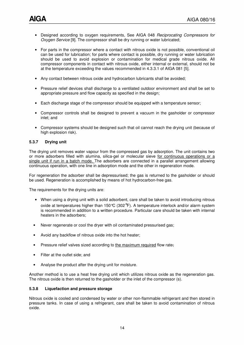
5.3.7 Drying unit
The drying unit removes water vapour from the compressed gas by adsorption. The unit contains two or more adsorbers filled with alumina, silica-gel or molecular sieve for continuous operations or a single unit if run in a batch mode. The adsorbers are connected in a parallel arrangement allowing continuous operation, with one line in adsorption mode and the other in regeneration mode.
For regeneration the adsorber shall be depressurised; the gas is returned to the gasholder or should be used. Regeneration is accomplished by means of hot hydrocarbon-free gas.
The requirements for the drying units are:
• When using a drying unit with a solid adsorbent, care shall be taken to avoid introducing nitrous
oxide at temperatures higher than 150°C (302°F). A temperature interlock and/or alarm system
is recommended in addition to a written procedure. Particular care should be taken with internal heaters in the adsorbers;
• Never regenerate or cool the dryer with oil contaminated pressurised gas;
• Avoid any backflow of nitrous oxide into the hot heater;
• Pressure relief valves sized according to the maximum required flow rate;
• Filter at the outlet side; and
• Analyse the product after the drying unit for moisture.
Another method is to use a heat free drying unit which utilizes nitrous oxide as the regeneration gas. The nitrous oxide is then returned to the gasholder or the inlet of the compressor (s).
5.3.8 Liquefaction and pressure storage
Nitrous oxide is cooled and condensed by water or other non-flammable refrigerant and then stored in pressure tanks. In case of using a refrigerant, care shall be taken to avoid contamination of nitrous oxide.
AIGA AIGA 080/16
15
5.3.8.1 High pressure storage (ambient)
For high pressure storage, the nitrous oxide is liquefied by water cooling (10°C to 15°C (50°F to
59°F)) and stored at ambient temperature and pressure between 45 bar and 55 bar (652 to 797 psi).
In most cases, this type of storage is an intermediate storage prior to transfer to a low pressure tank.
The requirements for high pressure storage, (ambient) are:
• high-pressure alarm and shut off alarm on intermediate storage tanks (if not installed at the compressor) to shut down the compressor;
• pressure relief valves sized according to the compressor’s flow rate capacity; and
• method to measure product content, for example, level or weight.
5.3.8.2 Low pressure storage (refrigerated)
Low-pressure liquefaction and storage is a safer option than high pressure storage because of the properties of nitrous oxide and the large volumes involved.
For low pressure storage, the nitrous oxide is liquefied by a refrigerant to temperatures between
–20°C and –30°C (-4°F and -22 °F ) and stored under pressure between 15 bar and 20 bar (217.5 psi
and 290 psi) in an insulated tank. For additional information see EIGA Doc 176 [1].
An alternative process for transferring nitrous oxide to low pressure storage is to remove product from the intermediate high pressure storage and pass it through an expansion valve.
The requirements for low pressure storage (refrigerated) are:
• For non-vacuum insulated tanks: Internal cooling coil operated with refrigerant to maintain nitrous oxide as a liquefied gas.
• Avoid the refrigerant coming into contact with the product.
• Pressure relief valves sized according to the maximum compressor’s flow rate capacity loss of insulation, or external fire ;
• Method to measure product content, for example level or weight.
6 Periodic inspection and maintenance
6.1 General
Periodic inspection and maintenance are required to ensure that the installation is well preserved and kept in safe condition. The responsibility for the inspection, maintenance and repair shall be established between the original equipment manufacturer, the user and if necessary with the local authorities. Routine inspection and maintenance of equipment should be carried out on a planned basis and be recorded.
The production site shall be inspected regularly to ensure that it is maintained in a proper condition and that safety distances originally specified are always maintained.
AIGA AIGA 080/16
16
An installation dossier shall be kept on site. This dossier may include the following, in accordance with local regulatory requirement:
• process and instrumentation diagrams;
• pressure vessel or tank dossiers; and
• operating and maintenance instructions.
Maintenance shall include, but not be limited to the following;
• checking the condition of the reactor, compressor, pressure vessels and tank, piping and accessories;
• checking the proper operation and setting of all the control loops;
• checking the operability of the valves;
• minor repairs, for example, changing of seals;
• cleaning; and
• checking of the reactor emergency cooling water system, see 5.3.2.3.
Inspection, maintenance and repairs shall only be carried out by personnel trained for the tasks.
Equipment shall not be taken out of service for repair until all pressure has been released. Any leakage shall be rectified promptly and in a safe manner. Only original spare parts should be used. If this is not possible the suitability of the spare part shall be approved by a competent person.
The maintenance and assembly of equipment shall be carried out in clean, oil free conditions. All tools and protective clothing (such as overalls, gloves and footwear) shall be clean and free of grease and oil. All equipment in contact with nitrous oxide shall be suitable for oxygen service, be cleaned, inspected, and labeled as cleaned for oxygen service.
6.2 Pressure relief devices
Regular visual inspections of the pressure relief devices shall be carried out during normal operation.
A periodic test of each relief valve shall be carried out to demonstrate its fitness for a further period of service. Pressure relief valves should be tested in accordance with EIGA Doc 24 Vacuum insulated cryogenic storage tank systems pressure protection devices [10] unless national regulations dictate more stringent requirements. The requirements of National Board of Inspection Code (NBIC), U.S. DOT, and Transport Canada (TC) apply in North America.
Bursting disc elements can deteriorate with time resulting in their relief pressure rating being reduced. It can therefore be necessary to replace disc elements from time to time.
Where block valves are installed upstream of pressure relief devices to allow their inspection with the system in operation, specific locking systems and operational procedures shall exist to assure that the safety devices are not isolated after the testing. At least one safety device shall be kept in operation during the testing of the second one.
6.3 Ancillary equipment
Ancillary equipment other than previously detailed (including, but not limited to: level gauges and level transmitter, pressure and temperature gauges and transmitters, pressure reducers) shall be
AIGA AIGA 080/16
17
maintained in accordance with either original equipment manufacturers’ recommendations or national codes, whichever is the more stringent.
6.4 Modifications and changes
No modification shall be made to a plant, equipment, control systems, process conditions and operating procedures without authorization from a responsible manager or their delegate.
Any modifications shall be carried out in accordance with the applicable design code; some modifications can require consultation with the original equipment manufacturer.
Proposed modifications shall be evaluated for safety, health and environmental impact and a signed document should be available before the change can be implemented. The document should be signed for a second time before the equipment is released to become operational. The document AIGA 010 Management of change [11] gives guidance on how implement such a procedure and should be referred to in Asia. Management of change in addition to any regulatory requirements..
7 Training and protection of personnel
7.1 Work permit
Before maintenance is carried out on the installation a written work permit for the particular type of work (for example work on process piping, hot work, entry of vessels, electrical work,) shall be issued by an authorized person to the individual(s) carrying out the work.
Recommendations and prescriptions about work permits are described in AIGA 011 Work Permit Systems [12] for Asia. United States OSHA and Federal and provincial regulations in Canada address work permit requirements in North America.
7.2 Entry into vessels
In addition to any regulatory requirements the following precautions, as applicable, shall be observed before entering any vessel, such as a storage tank:
• Complete emptying and purging of the tank contents;
• Ensure inner tank is approximately at ambient temperature before entry is permitted;
• Complete isolation of the process lines from other equipment which could still be in service, either by blanking discs or physical disconnection;
• Analysis of the atmosphere in the vessel at several selected points with a suitable gas detector. It could be necessary to measure the atmosphere regularly or continuously and to install forced ventilation while work is in progress;
• Presence of standby person (s) outside or adjacent to the access manhole;
• Use of appropriate safety equipment including, but not limited to harnesses, protective clothing, fire extinguishers; and
• Availability of rescue equipment (including, but not limited to harnesses, self-contained breathing apparatus, winches, radio links.)
Attempts to rescue affected persons from vessels or where oxygen-deficient atmosphere can be present should be made only by persons who are wearing and trained in the use of breathing apparatus and who are familiar with confined space entry procedures.
AIGA AIGA 080/16
18
The victim is often not aware of the asphyxia. If any of the following symptoms appear in situations where asphyxia is possible and breathing apparatus is not in use, move the affected person immediately to the fresh air, and if necessary following up with artificial respiration.
7.3 Training of personnel
All personnel directly involved in the commissioning, operation and maintenance of production systems shall be fully informed regarding the hazards associated with nitrous oxide and ammonium nitrate and trained as applicable to operate or maintain the equipment. Recommendations and prescriptions about training of personnel are described in EIGA Doc 23 Safety training of employees [13]. Training is covered in a variety of CGA publications as appropriate for the topic covered.
Training shall be arranged to cover those and other potential hazards that the particular operator is likely to encounter.
Training shall cover, but not necessarily be confined to the following subjects for all personnel:
• potential hazards of the fluids;
• site safety regulations;
• emergency procedures;
• use of firefighting equipment;
• use of protective clothing/apparatus including self-contained breathing apparatus sets where appropriate; and
• first aid treatment for cold temperature/thermal burns.
In addition individuals shall receive specific training in the activities for which they are employed.
It is recommended that the training be carried out under a formalised system and that records be kept of the training given and where possible, some indication of the results obtained, in order to show where further training is required.
The training programme should provide for refresher courses on a periodic basis.
8 Emergency procedures
Emergency procedures shall be prepared to include the event of spillage of fluids. It is advisable that emergency procedures are prepared in conjunction with the emergency services or fire brigade and that local conditions are considered.
The procedures shall be readily available to all personnel involved, regularly practised and checked periodically that they are up to date. Employees likely to be affected shall know the actions required to minimise the adverse effects of such spillage.
The procedure should consider:
• properties of the refrigerated liquefied gases;
• quantities involved;
• local topography; and
• design and equipment of the storage system.
AIGA AIGA 080/16
19
The following guidelines should be used for formulating emergency procedures:
• raise the alarm;
• summon help and emergency services;
• notify fire brigade immediately (if necessary);
• evacuate all persons from the immediate danger area and seal it off;
In case of leakage/spillage;
• tighten up leaks if this can be done without risk;
• allow liquid to evaporate; and
• prevent liquid from entering sewers, pits, trenches
In case of fire;
• keep vessel cool by spraying it with water; and
• do not spray water directly on valves or safety equipment
• alert public to possible dangers from vapour clouds and evacuate when necessary.
The procedure shall include:
• listing of emergency equipment required
• nomination of back-up personnel/organization for managing emergencies and procedures for contacting them both during and outside work
9 References
Unless otherwise specified the latest edition shall apply.
[1] Guide Good Manufacturing Practice in Europe, http://ec.europa.eu/
[2] U.S. FDA and Health Canada Good Manufacturing Practices www.fda.gov; www.hc-sc.gc.ca/
[3] NFPA 99, Health Care Facilities Code in the United States www.nfpa.org
[4] CSA Z305.1, Nonflammable Medical Gas Piping Systems in Canada for medical gas piping systems www.scc.ca
[5] AIGA 081.176 Safe Practices for Storage and Handling of Nitrous Oxide www.asiaiga.orgG
[6] CGA G-8.1 Standard for nitrous oxide systems at customer sites www.cganet.com
[7] EIGA Doc. 112 Environmental Impacts of Nitrous Oxide Plants www.eiga.eu
[8] UN Recommendations on the Transport of Dangerous Goods, Model Regulations www.unece.org
[9] AIGA 048, Reciprocating Compressors for Oxygen Service. Code of Practice www.asiaiga.org
AIGA AIGA 080/16
20
[10] EIGA Doc 24, Vacuum Insulated Cryogenic Storage Tank Systems Pressure Protection Devices www.eiga.eu
[11] AIGA 010, Management of Change www.asiaiga.org
[12] AIGA 011, Work Permit Systems www.asiaiga.org
[13] EIGA Doc 23, Safety Training of Employees www.eiga.eu