Embed Size (px)
Citation preview
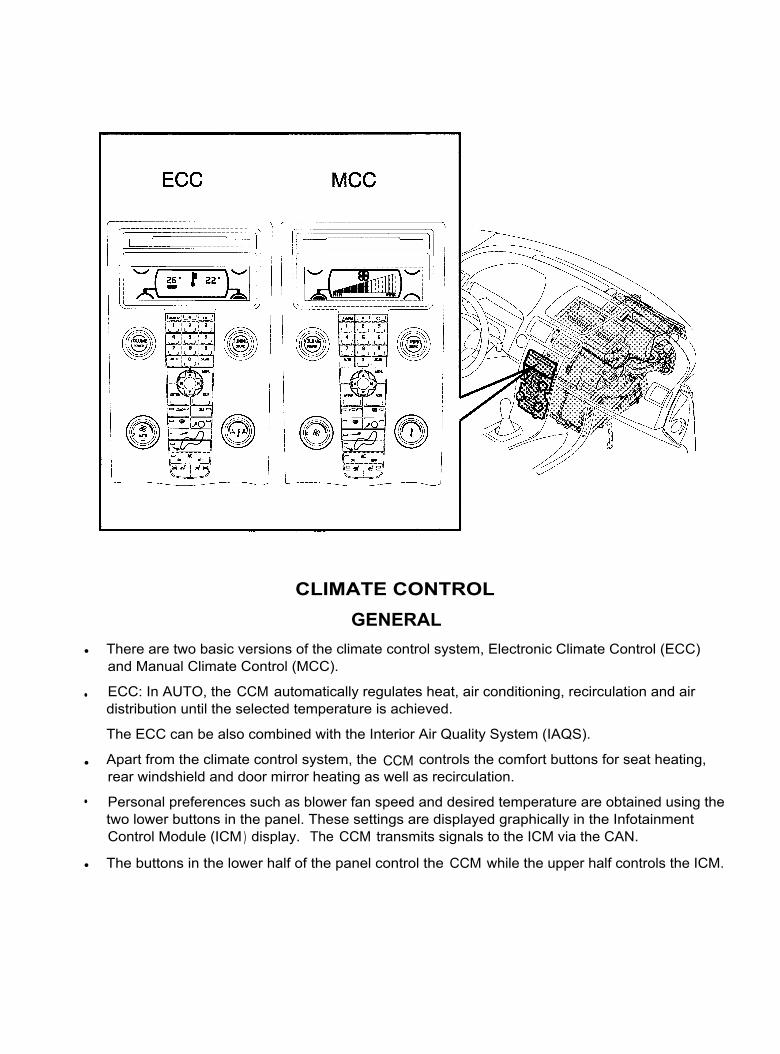
CLIMATE CONTROLGENERAL
•
There are two basic versions of the climate control system, Electronic Climate Control (ECC)and Manual Climate Control (MCC).
•
ECC: In AUTO, the CCM automatically regulates heat, air conditioning, recirculation and airdistribution until the selected temperature is achieved.
The ECC can be also combined with the Interior Air Quality System (IAQS).
•
Apart from the climate control system, the CCM controls the comfort buttons for seat heating,rear windshield and door mirror heating as well as recirculation.
•
Personal preferences such as blower fan speed and desired temperature are obtained using thetwo lower buttons in the panel. These settings are displayed graphically in the InfotainmentControl Module (ICM ) display. The CCM transmits signals to the ICM via the CAN.
•
The buttons in the lower half of the panel control the CCM while the upper half controls the ICM.

DEFROSTER VENTS
The vents for the windshield defroster direct air at the windshield for heating and demisting. A smallamount of air is directed at the lower part of the windshield through a narrow slot in the dashboard.This heats and de-ices the wiper blades. These air ducts are integrated into the structure of thedashboard.
Air also flows to the sides of the dashboard and into ducts integrated into the door panels. From thereair is directed at the windows in the front doors.
DASHBOARD VENTS
There are four vents in the dashboard. The air flow can be directed and adjusted individually throughdampers.
FLOOR VENTS
There are two front floor vents and two rear floor vents. At the front, the vents are on either side of thecenter console. In the rear, the vents are on the undersides of the driver and passenger seats.
EXTRACTOR DUCTSIn the S40 the air in the passenger compartment passes through the parcel shelf into the cargocompartment. Then the air is extracted through non-return valves that open with overpressure.
In the V50, like the V40, the air is extracted through non-return valves that open with overpressure.

AIR FLOWThe blower fan (2) pulls in air and directs it into the climate control unit. The air entering the passengercompartment is controlled by the position of the outside air/recirculation drum (1).
All air first passes the particle/multi-filter (12) and the evaporator (11). Then the temperature damperregulates (8) how much air passes the heater element (10).
I n ECC the right-hand and left-hand side temperature dampers can be controlled independently of eachother. In MCC the right-hand and left-hand side temperature dampers are controlled together.
When air has passed through/past the heater element the air flow is controlled by the position of theventilation dampers (5), the floor dampers (7) and the defroster dampers (4).
Recirculation is achieved by turning the outside air/recirculation drum.
Time Limited Recirculation, MCC and ECCIn the ICM climate control system menus there is a function for selecting time limited or constantrecirculation.
I f time limited recirculation is selected, the following applies:
•
I f the outside temperature is < +7°C the system returns to outside air after 3 minutes.
•
I f the outside temperature is > +20°C the system returns to outside air after 12 minutes.
•
At temperatures between + 7°C and + 20°C the system returns to outside air between 3 -12minutes in a linear fashion.
Speed Compensation, MCC and ECC
To maintain a constant air flow in the passenger compartment, the CCM uses the vehicle speed signalfrom the Brake Control Module (BCM) to regulate the speed of the blower fan. In general, when thespeed of the vehicle increases the speed of the blower fan decreases.
The fresh air damper adjusts the intake air flow at high speeds.
The advantage of automatic speed compensation is that the blower fan speed does not need to beadjusted manually to adjust the air flow at high speed.
Blower fan
The blower fan is brushless and has its own electronics with a power stage.
I t is controlled by the CCM and CEM. The principle is as follows:
•
The CCM requests a specific blower fan speed from the CEM via the CAN.
•
The CEM transmits a PWM signal corresponding to the requested speed to the blower fan.
•
When the blower fan has met the request, an acknowledgement signal of the fan speed andstatus is transmitted to the CEM.
•
The blower fan speed can be fine tuned in the ICM menu.
•
Diagnostic trouble codes are managed by the OEM.
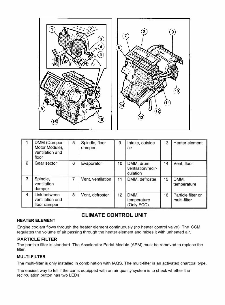
CLIMATE CONTROL UNITHEATER ELEMENTEngine coolant flows through the heater element continuously (no heater control valve). The CCMregulates the volume of air passing through the heater element and mixes it with unheated air.
PARTICLE FILTERThe particle filter is standard. The Accelerator Pedal Module (APM) must be removed to replace thefilter.
MULTI-FILTERThe multi-filter is only installed in combination with IAQS. The multi-filter is an activated charcoal type.
The easiest way to tell if the car is equipped with an air quality system is to check whether therecirculation button has two LEDs.
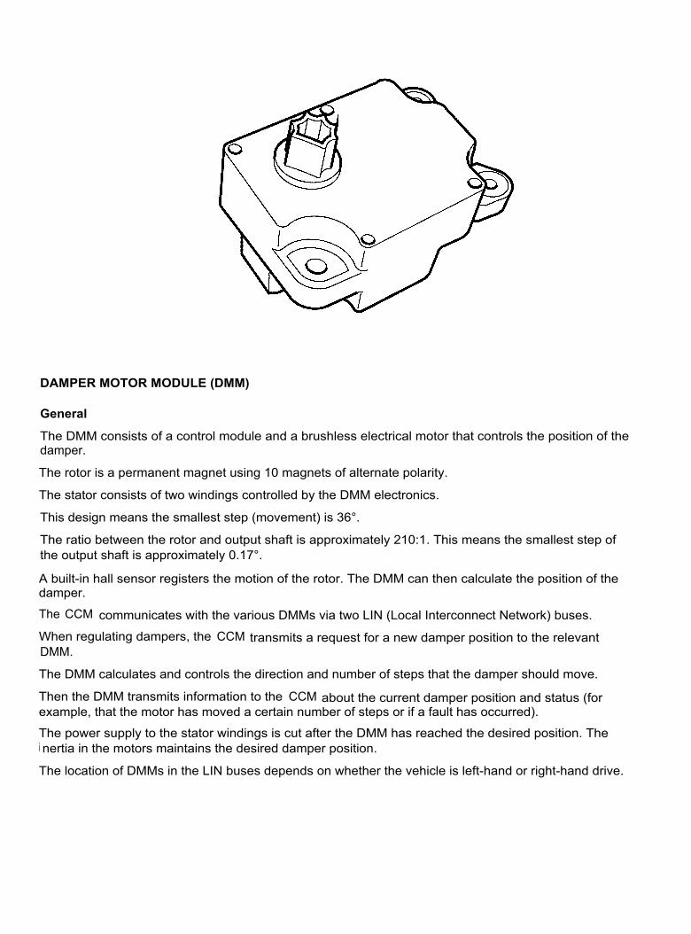
DAMPER MOTOR MODULE (DMM)
General
The DMM consists of a control module and a brushless electrical motor that controls the position of thedamper.
The rotor is a permanent magnet using 10 magnets of alternate polarity.
The stator consists of two windings controlled by the DMM electronics.
This design means the smallest step (movement) is 36°.
The ratio between the rotor and output shaft is approximately 210:1. This means the smallest step ofthe output shaft is approximately 0.17°.
A built-in hall sensor registers the motion of the rotor. The DMM can then calculate the position of thedamper.
The CCM communicates with the various DMMs via two LIN (Local Interconnect Network) buses.
When regulating dampers, the CCM transmits a request for a new damper position to the relevantDMM.
The DMM calculates and controls the direction and number of steps that the damper should move.
Then the DMM transmits information to the CCM about the current damper position and status (forexample, that the motor has moved a certain number of steps or if a fault has occurred).
The power supply to the stator windings is cut after the DMM has reached the desired position. Thei nertia in the motors maintains the desired damper position.
The location of DMMs in the LIN buses depends on whether the vehicle is left-hand or right-hand drive.
Location
The ECC has five DMMs that regulate the following dampers:
•
Defroster dampers.
•
Temperature damper, right.
Temperature damper, left.
•
Ventilation and floor dampers. The dampers are connected to each other by control arms. If onedamper closes, the other damper opens and vice versa.
•
The drum that controls the fresh air intake and recirculation.
The MCC has four DMMs that regulate the following dampers:
•
Defroster dampers.
•
Temperature dampers, left and right-hand sides.
•
Ventilation and floor dampers. The dampers are connected by control arms. If one damper closes,the other damper opens and vice versa.
•
The drum that controls fresh air intake and recirculation.
Other
•
When replacing a DMM, the CCM must identify the new damper motor function and position. This iscarried out via VADIS.
•
Each DMM receives its power supply from the OEM.
•
There are diagnostics for each DMM.
•
There is only one version of the DMM. It isn't dependent on the location or function.
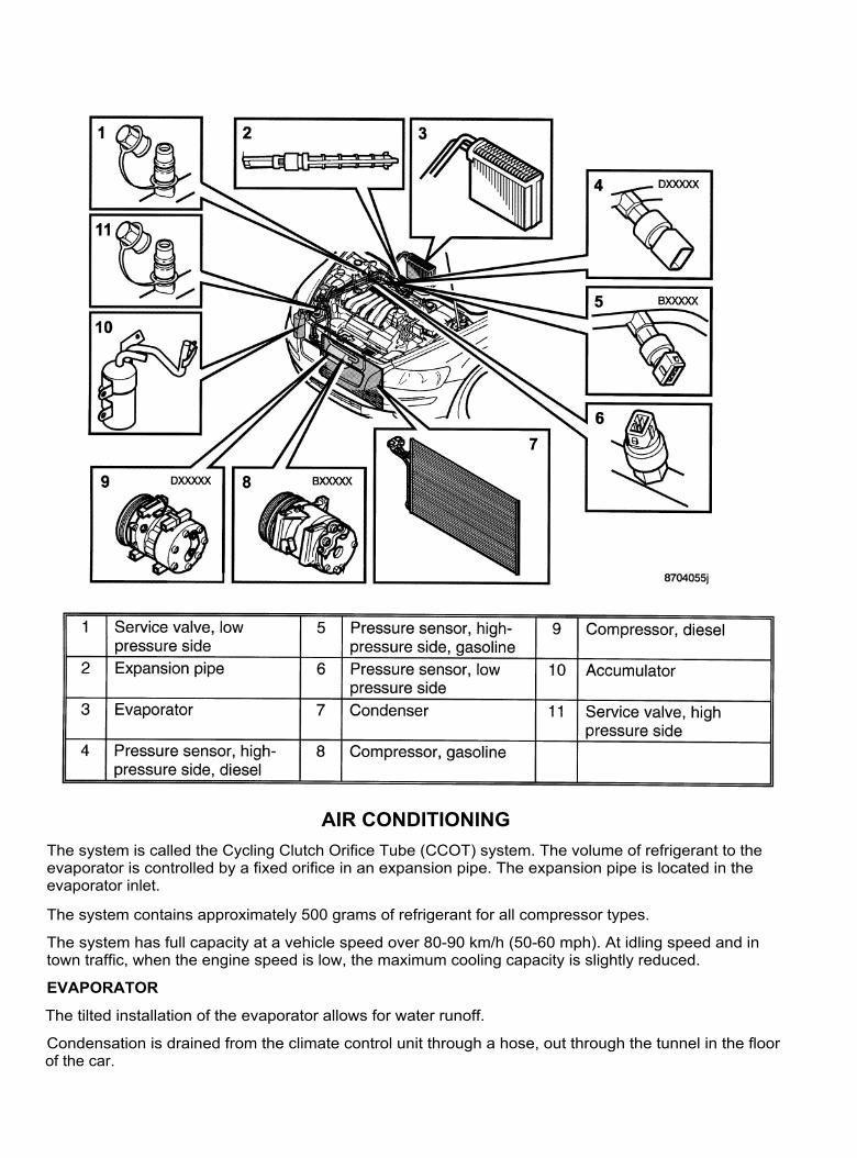
AIR CONDITIONINGThe system is called the Cycling Clutch Orifice Tube (CCOT) system. The volume of refrigerant to theevaporator is controlled by a fixed orifice in an expansion pipe. The expansion pipe is located in theevaporator inlet.
The system contains approximately 500 grams of refrigerant for all compressor types.
The system has full capacity at a vehicle speed over 80-90 km/h (50-60 mph). At idling speed and intown traffic, when the engine speed is low, the maximum cooling capacity is slightly reduced.
EVAPORATOR
The tilted installation of the evaporator allows for water runoff.
Condensation is drained from the climate control unit through a hose, out through the tunnel in the floorof the car.
COMPRESSOR
The Engine Control Module (ECM) controls the compressor based on a request from the CCM.
There are different compressors for gasoline and diesel engines.
The compressor has a fixed displacement. During normal operation, the ECM activates anddeactivates the compressor based on the signal from the pressostat on the low pressure side and incertain cases on the signal from the evaporator temperature sensor (ECC only).
Start Process
- If the engine coolant temperature is above -7°C the ECM activates the compressor in allcircumstances for 10 compressor revolutions during cranking.
- This function prevents hydrostatic lock when the compressor is activated.This eliminates the risk of the safety valve opening.
- The function also means that the compressor rotates regularly when it would normally be offcontinuously (during the winter months for example). This distributes oil around the variouscompressor components and the gaskets are softened up which extends their service life andimproves their seal.
Restrictions
The ECM can prevent compressor activation in the following circumstances:
•
The compressor is deactivated during wide open throttle for approximately 12 seconds.
•
I f the ECM sees the engine coolant temperature is too high, the compressor will not be activated.I f the engine coolant temperature is high, an activated compressor can also be deactivated.
Condenser
The connector pipes to the condenser are block connectors.
Accumulator
The accumulator is located on the low pressure side.
To facilitate any leak tracing, a fluorescent agent is added to the system at the factory. This mixes withthe system oil during operation.
Service Valves
I t is recommended that both service valves are used when draining the system.
Use the service valve on the low pressure side when filling the system.
The service valve for the high-pressure side is located under the NC packet cover plate.
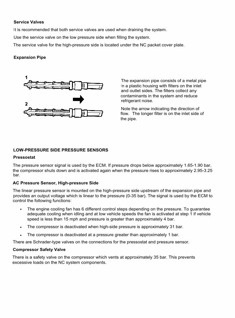
Expansion Pipe
The expansion pipe consists of a metal pipein a plastic housing with filters on the inletand outlet sides. The filters collect anycontaminants in the system and reducerefrigerant noise.
Note the arrow indicating the direction offlow. The longer filter is on the inlet side ofthe pipe.
LOW-PRESSURE SIDE PRESSURE SENSORSPressostat
The pressure sensor signal is used by the ECM. If pressure drops below approximately 1.65-1.90 bar,the compressor shuts down and is activated again when the pressure rises to approximately 2.95-3.25bar.
AC Pressure Sensor, High-pressure Side
The linear pressure sensor is mounted on the high-pressure side upstream of the expansion pipe andprovides an output voltage which is linear to the pressure (0-35 bar). The signal is used by the ECM tocontrol the following functions:
• The engine cooling fan has 6 different control steps depending on the pressure. To guaranteeadequate cooling when idling and at low vehicle speeds the fan is activated at step 1 if vehiclespeed is less than 15 mph and pressure is greater than approximately 4 bar.
•
The compressor is deactivated when high-side pressure is approximately 31 bar.
•
The compressor is deactivated at a pressure greater than approximately 1 bar.
There are Schrader-type valves on the connections for the pressostat and pressure sensor.
Compressor Safety Valve
There is a safety valve on the compressor which vents at approximately 35 bar. This preventsexcessive loads on the NC system components.

COMPONENTSThe CCM uses a number of input signals from different sensors to calculate and control the climatecontrol system.
Some information is from sensors connected to other control modules (such as, OEM). In these casesthe CCM obtains this information from the CAN. There are also sensors connected directly to the CCM.The sensors and signals used by the climate control system depend on whether the system is an MCCor ECC system.
OUTSIDE TEMPERATURE SENSOR (MCC and ECC)The outside temperature sensor, (an NTC resistor), is located in the left-hand door mirror. The OEMtransmits the signal over the CAN where it is captured by the CCM.
The CCM uses the signal to allow activation of the compressor down to a temperature of approximately -5°C.The ECC also uses the signal to regulate the direction of the air in the passenger compartment(defroster, ventilation or floor or combinations of these).
Diagnostic trouble codes for the outside temperature sensor are managed by the OEM.

PASSENGER COMPARTMENT TEMPERATURE SENSOR (ECC)The passenger compartment temperature sensor is wired directly to the CCM. The sensor is an NTCresistor.
A fan is mounted on the sensor. The fan supplies the sensor with air from the passenger compartment.This prevents the sensor from being affected by the heat of surrounding electronics.There are diagnostics for the passenger compartment temperature sensor and fan. Diagnostic troublecodes are managed by the CCM.
SUN SENSOR (ECC)The sun sensor is wired to the CEM.
The sun sensor consists of a photo-diode powered by the CEM. The conductivity of the photo-diodedepends on how much light it is exposed to.
The photo-diode is located under a diffuser to even out the light it receives. This reduces the sensitivityof the photo-diode to the angle of the sunlight it receives.I n addition to the sun sensor, there is a twilight sensor in the diffuser (in previous Volvo vehicles thiswas located in the CCM panel).
The signal from the sun sensor is used to compensate for high sun intensity. The CCM does this bydecreasing the temperature of the ventilation air, changing air distribution and increasing the speed ofthe blower fan.
There are diagnostics for the sun sensor. Diagnostic trouble codes are managed by the CEM.
IAQS AIR QUALITY SENSOR (ECC)The air quality sensor is connected to the CCM via LIN.
The air quality sensor is only installed with IAQS.
The air quality sensor transmits signals to the CCM if it registers increased levels of contaminatedoutside air.
The CCM uses the signal to regulate the DMM for outside air/recirculation.
The air quality sensor is located under the plenum chamber on the side of the outside air intake.
There are diagnostics for the air quality sensor. Diagnostic trouble codes are managed by the CCM.
EVAPORATOR TEMPERATURE SENSOR (ECC)The evaporator temperature sensor is connected to the CCM via a conventional cable. The sensor isan NTC resistor and the signal is a voltage signal.The CCM uses the signal from the evaporator temperature sensor to control requests toactivate/deactivate the compressor. This is to maintain a constant evaporator temperature ofapproximately +1°C to +3°C.
Using the signal from the evaporator temperature sensor allows a more stable regulation of thepassenger compartment temperature than in a CCOT system without an evaporator temperaturesensor.
There are diagnostics for the evaporator temperature sensor. Diagnostic trouble codes are managedby the CCM.

COMMUNICATIONThe CCM communicates with directly connected components and with other control modules andcomponents via the LIN and CAN.
LINThe CCM communicates with damper motors, the air quality system sensor and seat heaters via twoseparate LIN buses. The number of components on the LIN buses varies depending on the vehicleequipment (ECC/MCC and options) and whether the vehicle is right-hand or left-hand drive.
The following components communicate on LIN bus 1:
•
The DMM for air distribution
•
The DMM for temperature, left
•
The left-hand seat heaters.
The following components communicate on LIN bus 2:
•
The DMM for the defroster
•
The DMM for temperature, right (only ECC)
•
The DMM for recirculation
•
The air quality sensor
•
The right-hand seat heaters.

CONTROLThe CCM controls the following:
•
A request for A/C compressor activation is transmitted to the ECM via the CAN.•
Control of damper motors.•
The speed of the blower fan with a request to the CEM via the CAN.The regulation of the climate in the passenger compartment is based on the following input signals:
•
Passenger compartment temperature•
Outside temperature
•
Evaporator temperature
•
Sun intensityApart from these signals, the CCM also uses the following CAN signals:
•
Side window status, signals from the Driver Door Module (DDM) and Passenger Door Module(PDM) via the CAN
•
Door status, signal from the CEM via the CAN•
Speed, signal from the BCM via the CAN•
Windshield wiper status, signal from the Steering Wheel Module (SWM) via the CAN.
Side Windows and Doors (ECC)The CCM uses information about the status of side windows and doors to determine how it shouldcompensate for changes in the passenger compartment temperature. If the side windows or doors areopened, the CCM will not compensate for a change in passenger compartment temperature. The CCMmaintains the same level of climate control for the compressor and blower fan as it had before thewindow or door was opened.
Vehicle Speed (ECC)To maintain a constant air flow in the passenger compartment, the CCM uses the vehicle speed signalfrom the BCM to regulate the speed of the blower fan.
Windshield Wipers (ECC)To help limit windshield misting when it rains, the CCM controls the speed of the blower fan and theposition of the air vent dampers. This process takes place at temperatures between approximately 0° Cand approximately +20° C.
The CCM uses CAN signals which indicate the windshield wipers are active as a condition that it israining.
The CCM receives information in the following ways:•
The SWM (Steering Wheel Module) transmits signals via the CAN about the position of thewindshield wiper stalk. The signal is managed by the CEM which transmits the signal onwardon the low speed side of the CAN. The CCM picks up the signal and starts to control.
•
I f the car is equipped with a rain sensor the CCM also uses the rain sensor signal.The Rain Sensor Module (RSM) requests that the Wiper Motor Module (WMM) activates thewipers via the CEM. The CEM also transmits the signal to activate the wipers on the CAN. TheCCM picks up the signal and starts to control.
Control occurs in the following ways:•
The CCM (via the CEM) requests an increase in fan speed if the blower fan speed is low.
•
The CCM controls the air vent dampers so that the air flow to the windshield increases.The A/C compressor is switched on which reduces moisture in the incoming air to the passengercompartment.
The WWM receives information via the SWM to detect if the wipers encounter an obstruction. TheWWM will make three attempts and then shut off. To reset the WWM, turn the wiper switch OFF.
EXAMPLES of DIFFERENT OPERATIONAL CONDITIONS
Defroster, MCC and ECC
The principles are the same for the ECC and MCC systems.
Air flow is directed at the windshield. Blower fan speed is dependent on the coolant temperature andoutside temperature.
On starting a cold engine in temperatures below 0°C, the blower fan speed is low until the temperatureof the coolant has reached approximately 40°C (varies depending on outside temperature). Blower fanspeed then increases to full speed. Blower fan speed then drops depending on passengercompartment temperature (ECC).
I n defroster mode, the compressor is always connected to dehumidify the air. This is down to anoutside temperature of approximately -5°C.
If the pressostat registers a pressure below approximately 1.65-1.90 bar or the evaporator temperaturesensor registers a temperature below +1 °C to +3°C the compressor is deactivated despite the outsidetemperature above -5°C.
Ventilation, ECC
For maximum cooling in the passenger compartment, most air is directed through the ventilation vents.The AC compressor is activated and the blower fan runs at high speed until the signal from thepassenger compartment temperature sensor corresponds to the set temperature.
Heat, ECC
For maximum heating at low ambient temperatures in cold climates, most air is directed through thedefroster dampers for the first few minutes. Air is then distributed to the floor dampers as well. Theblower fan speed is low until the coolant temperature is high. Then the blower fan speed increases.

DIAGNOSTIC FUNCTIONSNEW FUNCTIONS in VADISIdentifying Damper Motors
This function identifies DDMs when they have been replaced.
When replacing a DDM, the new unit will have a general identity on the LIN bus. For the CCM toidentify the DMM, the DDM must be run to its limit positions. The number of steps that the motor goesthrough between limit positions is unique for each damper. This allows CCM to know what functionalitythe new DDM has.
Checking a LIN bus
This service is used to check the components that communicate with the CCM via the LIN buses.I f a fault arises in either of the LIN buses, a diagnostic trouble code will be stored.
The LIN buses are checked continuously by the CCM.
General
DTCs are stored in the CCM if the CCM detects a fault. Every DTC has a counter which records thenumber of operating cycles which have been fault-free since the DTC was stored. A fault which isdetected in each operating cycle is defined as permanent. A fault which is detected in not all operatingcycles is defined as intermittent.
An operating cycle is the period from when the ignition was turned on, and then on for at least 10seconds and was finally turned off for at least 10 seconds.