Embed Size (px)
Citation preview

Mammography– recent technical developments
and their clinical potential
2002:08 BENGT HEMDAL, INGVAR ANDERSSON, ANNE THILANDERKLANG, GERT BENGTSSON, WOLFRAM LEITZ,NILS BJURSTAM, OLOF JARLMAN AND SÖREN MATTSSON

SSI rapport : 2002:08
maj 2002
ISSN 0282-4434
FÖRFATTARE/ AUTHOR: Bengt Hemdal1, Ingvar Andersson2, Anne ThilanderKlang3, Gert Bengtsson4, Wolfram Leitz5, Nils Bjurstam6, Olof Jarlman4 and SörenMattsson1
1 Department of Radiation Physics, Malmö University Hospital, 2 Department of Diagnostic Radiology,
Malmö University Hospital, 3 Department of Medical Physics and Biomedical Engineering, Sahlgrenska
University Hospital, 4 Department of Diagnostic Radiology, Lund University Hospital, 5 Swedish Radia-
tion Protection Authority, 6 Centre for Breast Imaging, Department of Radiology, University of North
Norway, Troms
AVDELNING/ DIVISION: Avdelningen för personal- och patientstrålskydd / Depart-ment of Occupational and Medical Exposures
TITEL/ TITLE: Mammography – recent technical developments and their clinical potential
SAMMANFATTNING: Syfte: Att gå igenom den senare tidens utveckling i röntgentek-nik för mammografi med både digital och skärm-film teknik för att utvärdera deraskliniska potential och analysera möjliga framtida utvecklingsmöjligheter.
Material och metoder: Den vetenskapliga litteraturen har gåtts igenom, konferenserhar bevakats och kontakter med kollegor har utvecklats. Företag inom verksamhet-sområdet har lämnat uppgifter och blivit inbjudna för presentationer. Egen erfarenhethar samlats av olika mammografiutrustningar med skärm-film och digital teknik.
Resultat och slutsatser: Trots tillgången till viktiga kompletterande tekniker somultraljud och magnetkamera (MR eller MRI), är röntgentekniken mammografi fort-farande standardteknik för medicinsk avbildning av bröst. Den är relativt enkel ochkostnadseffektiv, och är den för närvarande enda realistiska tekniken för storskaligahälsoundersökningar. Fortfarande är det i stort sett den enda metod, med vilkenman kan upptäcka icke invasiv bröstcancer.
Utrustning för digital mammografi är kommersiellt tillgänglig både med liten ytaoch med fullfältsteknik (FFDM). Utvecklingen av FFDM utrustningar är nu intensiv,liksom utvecklingen av anpassade arbetsstationer och datorstödd diagnostik (CAD).Trots detta har introduktionen av digital mammografi varit mycket långsam jämförtmed de flesta andra röntgenundersökningar p g a höga kostnader och tekniska pro-blem vad gäller de höga kraven på bildkvalitet och dos i mammografi liksom kravenpå anpassat arbetsflöde vid hälsoundersökningar och lämpliga presentationsformer.Granskning på ljusskåp av utprintade filmbilder från digitala mammografiutrust-ningar har hittills varit det vanligaste granskningssättet, men för att kunna utnyttjaden digitala tekniken full ut, diagnostiskt såväl som logistiskt, måste bildgranskningpå monitor tillämpas.
FFDM teknik har potential för signifikant bättre bildkvalitet eller signifikant lägrestråldos än skärm-film teknik (SFM), eller båda delarna. Det krävs ytterligare forsk-ning och utveckling för att helt kunna utnyttja denna potential.
Investeringskostnaderna är mycket högre för digital än för skärm-film mammografiidag. Icke desto mindre kommer digital mammografi högst sannolikt att ersättaskärm-film mammografi i stor utsträckning, särskilt i storskaliga tillämpningar. Fort-satt utvärdering av digital och skärm-film mammografi måste genomföras vad gällerbildkvalitet och stråldos liksom diagnostiskt utbyte i form av sensitivitet, specificitetoch kostnadseffektivitet. Frågan är huruvida de högre investeringskostnaderna upp-vägs av ökad sensitivitet och specificitet, mer rationell hantering och lagring, samt avmöjligheterna att använda nya tekniker för framställning och analys av bilder.
Den framtida användningen av mammografiteknik kommer förmodligen att variera,med tillgång till olika slags digital teknik och även fortsatt användning av skärm-film, beroende på patientvolym och medicinska såväl som ekonomiska aspekter.
SUMMARY: Purpose: The recent technical developments in digital as well as screen-film X-ray mammography have been reviewed in order to evaluate their clinical po-tential and to analyse possible lines for future development.
Material and methods: The scientific literature has been reviewed, conferences co-vered and contacts with colleagues developed. Companies in the field have been in-

quired and invited for presentations. Own experience has been gathered from diffe-rent screen-film and digital mammography systems.
Results and conclusions: Although there are important complementary techni-ques such as ultrasound and magnetic resonance imaging (MRI), X-ray mammo-graphy is still the golden standard for breast imaging. It is relatively simple andcost-effective, and it is presently the only realistic technique for screening in a largescale. It is still largely the only technique that can detect breast cancer in a preinva-sive stage.
Equipment for digital mammography is commercially available both with small areaand full field technique (FFDM). The development of FFDM systems is now intense,as well as the development of dedicated workstations and computer-aided detection(CAD). In spite of this, the introduction of digital mammography has been very slowcompared to most other X-ray examinations due to high costs and technical challen-ges to meet the high demands on image quality and dose in mammography as well asthe demands on specialised workflow support for screening mammography and sui-table display techniques. Film reading of digital mammograms has been the mostcommon display mode so far, but to take full advantage of the digital concept, diag-nostic as well as logistic, monitor reading must be applied.
There is a potential of FFDM systems for significantly higher image quality or sig-nificantly lower dose than screen-film mammography (SFM), or both. Further re-search is necessary to fully use this potential.
The investment costs are much higher for digital than screen-film mammographytoday. Nevertheless digital mammography will most likely replace screen-filmmammography to a large extent, especially in large-scale operations. However,further evaluation of digital and screen-film mammography must be performed re-garding image quality and dose as well as diagnostic outcome in terms of sensitiv-ity, specificity and cost-effectiveness. The question is whether the higher investmentcosts are outweighed by increased sensitivity and specificity, more rational hand-ling and storing, and the possibilities to use new techniques for image productionand analysis.
The future use of mammography technique will probably be varying, with the avai-lability of different kinds of digital techniques and also the continued use of screen-film, depending on the patient volume and medical as well as financial aspects.
Författarna svararsjälva för innehålleti rapporten.
The conclusions andviewpoints presentedin the report arethose of the authoran do not necessarilycoincide with thoseof the SSI.

1
Mammography –recent technical
developments and their clinical potential
Content ABBREVIATIONS 2
INTRODUCTION 2
BACKGROUND 2
DEVELOPMENT OF CONVENTIONAL MAMMOGRAPHY 3
CLINICAL MAMMOGRAPHY AND SCREENING 3
ALTERNATIVE AND COMPLEMENTARY TECHNIQUES 3
SCREEN-FILM TECHNIQUE 4
IMAGE QUALITY AND DOSE 7
SENSITIVITY AND SPECIFICITY 8
COST-EFFECTIVENESS 8
DEVELOPMENT OF DIGITAL MAMMOGRAPHY 8
INDIRECT DETECTION TECHNIQUE 9
DIRECT DETECTION TECHNIQUE 12
DIRECT PHOTON COUNTING TECHNIQUE 13
POST PROCESSING AND DISPLAYING 16
ARCHIVAL AND RETRIEVAL 18
SPECIAL TECHNIQUES IN DIGITAL MAMMOGRAPHY 18
IMAGE QUALITY AND DOSE 19
CLINICAL POTENTIAL OF DIGITAL MAMMOGRAPHY 20
CONCLUSIONS 21
ACKNOWLEDGEMENTS 22
PRELIMINARY REPORTS 22
REFERENCES 22
FIGURES 30

2
Abbreviations aSe aSi AEC AGD ASIC
amorphous selenium amorphous silicon automatic exposure control average glandular dose application specific integrated circuits
CAD CCD CMOS CR
computer-aided detection charge-coupled device complimentary metal-oxide semiconductor computed radiography
DM DQE FDA FFDM
digital mammography detective quantum efficiency Food and Drug Administration, USA full-field digital mammography
HRT MRI MTF OD PACS PMA PMMA RAM RIS SF
hormone replacement therapy magnetic resonance imaging modulation transfer function optical density of a film picture archiving and communication system premarket approval polymethyl methacrylate random access memory radiology information system screen-film
SFM SNR TDI TFT
screen-film mammography signal to noise ratio time delay integration thin film transistor
Introduction Mammography is one of the most frequent X-ray examinations, until now dominated by screen-film (SF) technique, however, challenged by digital mammography (DM). The technique shift has been expected for a long time, and since the analogue and digital techniques are different in many aspects, it was considered necessary to review the current situation and lines of development to be able to better foresee needs in future radiation protection actions. In a research project from the Swedish Radiation Protection Authority (P 1062.98), the recent technical developments of DM and their clinical potential has been studied in the light of developments of the conventional SF technique. As a background to this report we have reviewed the scientific literature, covered conferences in the field and developed contacts with manufacturers and colleagues. Comparative measurements have been carried out on different mammography systems.
Background Particularly during the last two decades, mammography has experienced an enormous expansion and in many countries it is one of the most frequent X-ray examinations, especially in Sweden [Leitz 1997] and other countries with nation-wide screening programs, e.g. the Netherlands, the United Kingdom, Finland and Australia. Screening mammography is in progress also in other European countries as for instance Norway, as well as in Canada and the USA. In 1982 there were only 134 mammography units in the USA, increasing to about 10 000 in 1990. The present annual number of mammographic examinations in Sweden is around 750.000 of which 80% is screening investigations and 20% is clinical investigations.

3
The frequent use of mammography and the large proportion of screening examinations has inspired a lot of effort in optimising the current technique, still dominated by screen-film. National [Socialstyrelsen 1998] and international [EC 1996a, Zoetelief et al. 1996, EUROATOM 1997] recommendations and legislation’s have been especially dedicated to mammography, in some cases together with other frequent X-ray examinations [EC 1996b]. Since the mid 90´s there has been a great interest in digital mammography, but the shift from screen-film to digital mammography has been slowed down by technical challenges and high costs due to the demands on high image quality and low absorbed dose in mammography. Both in clinical mammography and especially in screening, digital mammography is still uncommon. The purpose of this work is to evaluate the technical development and the clinical potential of digital mammography compared to screen-film technique. As a background, the development of conventional mammography is described briefly.
Development of conventional mammography Mammography with screen-film technique is fast and cost-efficient, with high sensitivity and specificity, which are important requirements for any screening activity. It is consequently not easy for a new technique like digital mammography to compete. However, there are limitations of screen-film mammography (SFM) that digital technique has a potential to remedy. Examples of important limitations are a limited dynamic range, a fixed display scale with low image contrast in the dense breast parenchymal area and environmental problems from chemicals in the processor. The efficiency to transfer information from the spatial distribution of X-ray quanta behind the breast to an image is described with the quantity detective quantum efficiency (DQE). The relatively poor DQE of screen-film techniques indicate a potential for improvement of the image quality and/or a reduction of the dose with digital systems.
Clinical mammography and screening Screening mammography differs from clinical mammography quantitatively rather than qualitatively. The large number of cases handled per time unit in screening implies special demands on rational processing including display, reading and storage of the images. The field size of present “full-field” mammography units is usually about 18 cm x 24 cm with an option to use 24 cm x 30 cm for large breasts. In clinical mammography there is also a need for imaging a small area (about 5 cm x 5 cm) with magnification of the image with a factor of about 1.7-2.0. This should also be possible to combine with a biopsy needle guidance system in stereotactic mode.
Alternative and complementary techniques There are a lot of techniques available for breast diagnosis, some of which are at the experimental stage. Although new breast imaging techniques are emerging and techniques such as ultrasound and magnetic resonance imaging (MRI), represent significant contributions, mammography is still the golden standard. There are several reasons for this, one being its relative simplicity, another its cost-effectiveness. Mammography is presently the only realistic technique for screening in a large scale. It is still largely the only technique that can detect breast cancer in a preinvasive stage. It has to be remembered that the final arbiter whether a lesion is benign or malignant cannot be imaging, but has to be cytology and histology. Therefore, the standard diagnostic battery in breast diagnosis is mammography, ultrasound, physical examination and needle biopsy. The main complementary imaging techniques to mammography are ultrasound and MRI, which both have the advantage of not using ionising radiation. The advantages of ultrasound are mainly that it is relatively inexpensive and that it works well also for dense breasts where mammography has difficulties. Ultrasound also plays an important role as guidance for needle biopsy. MRI should be performed as a contrast enhanced dynamic study and is then a very sensitive and moderately specific technique, which may provide unique information. Certain indications are already established, such as the investigation of unclear findings on conventional examinations, including multifocal malignant disease. Other established indications are the investigation of the postoperative/postirradiated/augmented breast and the work-up of

4
patients with metastatic disease in the axilla and negative conventional examinations. Other indications such as screening of the high-risk patient are not yet established. Among more infrequent techniques are computed tomography (CT), scintimammography with 99Tcm sestaMIBI (Cardiolite) or 111In octreotide, positron emission tomography (PET) with 18F DG or 11C methonine, transillumination, elastography, electric impedance imaging and thermography. None of these techniques represent any realistic alternative to mammography in large-scale breast imaging, but can be used as complementary techniques.
Screen-film technique The mammographic technique has been improved continuously since the introduction by pioneers such as Raoul Leborgne in Montevideo, Uruguay in the 1940´s [Leborgne 1951]. Modern mammography was developed by Charles Gros in France in the 1960´s. The revolutionary features were an X-ray tube optimised for soft tissue imaging with a molybdenum (Mo) anode, a Mo-filter and a compressing device. This type of unit and the introduction of rare-earth intensifying screens in the mid 1970´s were important for the enormous expansion of mammography during the last two decades. The technical evolution of mammography has continued. Reviews on the physics of modern screen-film mammography techniques have been made elsewhere [Barnes 1999, Haus 1999, Hendrick and Berns 1999]. Here follow a short discussion on screen-film (SF) technique with comments on digital mammography (DM):
X-ray unit Modern X-ray units usually have electrical motors that facilitate for example height adjustments and angulations. It has also highly developed ergonomics. Many special features have been developed in order to rationalise the work of image acquisition; a recent example is a moveable X-ray tube from Instrumentarium, Figure 1, for improved access to the patient. Comment DM: Using imaging plates and some other DM systems, conventional mammography X-ray units can be used, while e.g. scanning digital radiology systems must have a special X-ray unit. Ergonomics are important also with DM, but for some systems, e.g. the more space demanding scanning systems, it could be more difficult to develop an X-ray unit with good ergonomics.
X-ray tube Most current mammography systems have Mo-anodes combined with Mo-filtration, many in addition have rhodium (Rh) filtration. Some manufacturers also offer dual-anode tubes, such as Mo-Rh, General Electric, or Mo-W (tungsten), Siemens. The combination of Mo anode with Mo filtration produces a photon energy distribution, which is rather close to optimal (at least for an X-ray beam) for imaging small to medium sized breasts at tube potentials between 25 and 30 kV. Increasing the tube potential increases the penetration of the beam and thus decreases the mean absorbed dose. However, this also decreases image contrast by decreasing the attenuation differences. Switching to Rh-filtration as well as Rh- or W-anodes has the same effect [Thilander Klang 1997]. In Figure 2 examples of X-ray spectra illustrate the difference between the energy distribution of incident and transmitted photons for a breast simulated with 40 mm polymethyl methacrylate (PMMA). The information content is highest for low energy photons penetrating the breast, and the photons not transmitted will result in absorbed dose to the patient, which applies to all the photons below about 13-15 keV. It is evident from Figure 2 that e.g. the anode/filter combination W/Rh results in higher mean energy of transmitted photons than Mo/Mo at the same tube potential. Many modern mammography units have programs which automatically choose tube potential as well as filter, in some cases also anode on the basis of breast thickness (input from the compression device), sometimes also breast composition (input from the “AEC”, see below). The combination choosen should represent a reasonable compromise between image contrast and dose, so that the dose is not unnecessarily high for the imaging task [EURATOM 1997].

5
The tube current must be adequate to produce proper optical density (OD) of the film within a short exposure time. Exposure times over about one second imply a risk of added dose from reciprocity law failure. The tube current should be at least 80 mA, preferably 100 mA. Rh anodes cannot be operated at as high tube current as Mo and W-anodes due to a lower melting point. Comment DM: Digital detectors usually have a different response to X-rays than SF. Somewhat higher energies are generally used and modern X-ray tubes that are used for the conventional SF technique can be well suited also for DM, as e.g. in the case of GE Senographe 2000D. However, since the image can be post processed, the selection of X-ray energies with DM is not as critical as with SFM. A replacement of the X-ray tube could however be needed for other reasons, e.g. for scanning systems with high demands on heat loading capacity. With image plates the optimum combinations of anode/filter and tube potential seems to be rather similar to those of screen/film. Reciprocity law failure does not exist for digital detectors, but a reasonable exposure time is desirable for other reasons, e.g. less risk of motion unsharpness and better comfort for the patient. Scanning systems usually have an exposure time as long as about 5 seconds, which is a disadvantage.
Scatter control One important factor degrading image contrast is scattered radiation. The amount of scatter depends heavily on breast thickness and to some extent also on the area covered by the compressed breast. Compression reduces scatter and make the level of scatter more even. This is one of the reasons why breast compression is necessary to obtain a good mammogram with SF technique. Further effect can be obtained locally by compression of a smaller area, so-called spot compression, which can be combined with magnification and a smaller radiation field area. The most important part of scatter reduction is the anti-scatter grid. Such a grid consists of thin lead lamellae separated by a radiolucent spacer. The grid ratio (height of lead lamellae divided by interspace thickness) is usually 4:1 or 5:1. The grid should be moving during the exposure. The effect of the grid is to absorb a major part of the scattered radiation (75-85%) while transmitting a major proportion of the primary radiation (60-75%) [Barnes 1999]. As a result, image contrast is improved at the price of increased dose. Contrast improvement is related to breast thickness (as with scattered radiation), being larger with thicker breasts. Conventional linear grids reduce scatter efficiently only perpendicular to the grid septa, while there is little reduction in the direction parallel to the grid lines. Another solution is the cellular grid from Lorad (Figure 3), which has a square pattern and therefore controls scatter in two dimensions. These grids have been shown to further reduce scattered radiation [Rezentes et al. 1999] and thus to further improve image contrast compared to conventional grids without dose increase, if anode/filter Mo/Mo and tube potential 25-30 kV is used. An even more efficient way of reducing scatter is the slot scanning technique. The X-ray beam is collimated to a thin fan beam, which is scanned across the breast. Still another way of reducing scatter is geometric magnification using an air gap. The magnification factor is usually 1.7 -2.0. For magnification work a microfocus of nominal size 0.10 - 0.15 mm is necessary. Thus, mammography units that are used for work up (and not only screening) should be equipped with a microfocus. Comment DM: Scatter increase the noise also in DM, but scatter control is less important than in SFM, mainly because the image can be post processed. Therefore, contrast deterioration from scattered radiation can at least partly be compensated for. The anti-scatter grid is used in e.g. GE Senographe 2000D, but is actually not needed for small or medium sized breasts [Veldkamp et al. 2001]. The slot scanning technique is used with Fischer SenoScan and Sectra Microdose. Digital systems usually use zooming instead of geometric magnification, and therefore not the air-gap technique.

6
Compression device Optimal compression is a very important part of the mammography procedure. Compression improves contrast by reducing both the scatter and the mean energy of the X-ray photons penetrating the compressed tissue. Compression also reduces the dose to the breast. The motion of the breast is also reduced. Furthermore, the OD of the mammogram becomes more uniform. By proper compression, the structures of the breast are spread apart which makes image interpretation easier. A refinement of the compression is the bi-directional compression system, which takes into consideration the natural mobility of the breast. This should make it possible to include more of the juxtathoracic part of the breast in the imaging field. The same effect may be obtained with moving radiolucent sheets, which pull the breast into the imaging field during compression. Both techniques, provided by Planmed, are illustrated in Figure 4. Comment DM: Because of the wide dynamic range, the firm compression necessary in SFM mammography has not the same importance for the image quality, especially not in cases where the scattered radiation is practically eliminated, as with the scanning systems. It must however be stressed that compression is important also with DM because of the reduction of breast motion and the separation of structures of the breast. An exception to this is tomosynthesis (explained below). Also DM systems must include as much as possible of the juxtathoracic part of the breast in the imaging field. Special observation on this is motivated with DM systems, because of the space that might be needed for electronics at the edges of the detector.
Automatic exposure control Proper AEC-operation is essential to get optimal and reproducible OD of the films independent of breast thickness and beam quality used. AEC-devices have one or several sensors beneath the cassette, with the main function to stop the exposure at the right moment (i.e. resulting in a proper OD). The high-contrast screen-film systems used in mammography have a very limited exposure range, which put high demands on the AEC. The tendency in recent years of higher output of the X-ray tubes and higher sensitivity of the screen-film systems, results in a short and low signal from the AEC detector, which makes the task even more difficult. The sensor should have a certain size and should be possible to move away from the chest wall. The reason for this is that the exposure should be determined by the densest part of the breast. The AEC should meet certain standards, which may vary. One requirement is that the AEC should maintain a uniform film optical density to +/- 0.10 or 0.15 OD units when the thickness of the phantom varies from 2 to 7 cm PMMA for all techniques used [EC 1996a]. The AEC have been refined substantially during the last years. A novel AEC design has been presented by Instrumentarium using 8 detectors, optimised in size, location and shape, Figure 5. The most suitable detector can be automatically chosen at the beginning of the exposure from the detector with the lowest signal. In this way the densest part of the breast will always be properly exposed. AEC sensors could also have a sandwich design with filters, and a dual signal from the detector could be used for an estimation of the radiation quality behind the breast, and thus a measure of the breast composition. In this way the AEC could provide information for the automatic change of tube potential as well as filter, in some cases also anode, during the exposure (see “X-ray tube” above). Comment DM: With DM the exposure level is not that critical. It must still be balanced carefully between image quality and dose, but “under”- or “over”- exposure will result in more or less noise, but probably not ruin the image, as with screen-film. This is one important advantage of DM, which will reduce the frequency of retakes. Instead, there is a risk for unnecessarily high doses, because the image quality will improve with increased exposure. Another important difference from SF is that the AEC detector can be the same as the entire image detector, as in the full-field digital mammography (FFDM) system Senographe 2000D from General Electric (see below). With scanning systems the exposure level has to be determined in advance, and AEC is not used.

7
Screen-film and processing The dose has been reduced rather dramatically during the last decades from the originally used direct film technique, over the vacuum-cassette technique to the present cassette technique with the use of new efficient phosphors in the intensifying screens. At the same time, the image contrast has been dramatically improved, and the image latitude decreased. The introduction of rare earth intensifying screens in the mid 1970´s represented a major step forward. These screens could be combined with high-speed films reducing the dose. The screens are virtually always used as back-screens combined with a single -emulsion film in order to achieve optimal spatial resolution. Various phosphors have been used; one commonly used is gadolinium-oxysulfide (Gd2O2S:Tb) emitting visible light in the green spectral region (wave-length about 500 nm). Film processing is a critical link in the chain leading to a high quality mammogram. Sub-optimal image quality is frequently due to sub-optimal processing. The processing is one of the key factors determining the film contrast and the absorbed dose. Critical factors in the processing are temperature, processing time and replenishment rate. Comment DM: The basic idea of DM is to get rid of screen-film-processing, its limitations and variability. However, several other possibilities and problems occur, which will be discussed further.
Viewing conditions Viewing conditions are of greater importance than generally appreciated. Light boxes of adequate luminance (2000-6000 cd/m2) and reading conditions with a low level of ambient light (<50 lux) are important as well as masking of the films to reduce stray light [EC 1996a]. Comment DM: Viewing conditions are important for DM as well as for SFM. Display luminance of a monitor should be adequate (at least about 300 cd/m2) and the ambient light should be limited (<50 lux, dependent of the luminance).
Image quality and dose The goal in mammography is to consistently produce sufficiently high quality mammograms with minimal radiation exposure to the patient. Image contrast and spatial resolution are important determinants of image quality in mammography. One of the restrictions of SFM is its limited dynamic range. The characteristic S-shaped Hurter and Driffield (HD) dose response curve means that the contrast is high for intermediate exposure areas but low for both low and high exposure areas in the so called toe and shoulder of the curve. In other words, “dense” and “thin” areas of the breast are displayed with low contrast. Low contrast in the thin areas of the breast, i.e. the black areas of the film, means that the skin line and nearby subcutaneous structures often are difficult to see, except when using a bright light. However, it is unusual for breast cancer to have its epicenter in the subcutaneous area. Most important are the dense areas, where cancers are most difficult to detect. In these more or less white areas of the film a breast cancer usually is found from signs like spiculations, calcifications and architectural distortion. To find breast cancer with no other sign than a mass in a dense breast parenchyma can be as difficult as finding a snowball in a snowdrift. The increased use of hormone replacement therapy (HRT) in recent years tends to make this problem worse [Kavanagh et al. 2000]. Screening of younger women also highlights this problem. Improved contrast above all in the imaging of the dense part of the breast could significantly improve the detectability of breast cancer. The average glandular dose (AGD) in the breast per mammogram is in the order of 1 mGy for the average breast using state of the art equipment, e.g. in Sweden [Leitz and Jönsson 2001]. The dose recommendations vary. The Swedish recommendation [Socialstyrelsen 1998] may be mentioned as an example: The AGD is not allowed to exceed 1.5 mGy at the OD setting used and should not exceed 1.0

8
mGy at net OD 1.0 as measured with a 4.5 cm PMMA phantom according to the European protocol [Zoetelief et al. 1996]. Although the dose has been reduced rather dramatically during the last decades, the exposure of a large number of healthy individuals in screening programs remains of some concern. This must be considered in a cost-effectiveness analysis (see below).
Sensitivity and specificity The mammograms of 15 – 30 per cent of women with breast cancer who undergo screening are interpreted as negative. In more than half of such cases mammographic signs of breast cancer can be identified retrospectively [Laming and Warren 2000]. There are many explanations for these shortcomings such as limitations in the technique, perception problems and interpretation errors. Thus, there is room for improvement. Digital mammography and spin-off techniques such as computer-aided detection (CAD) may represent such improvements. A high specificity is at least as important as a high sensitivity. In population based screening, the specificity should be about 97%; lower specificity lead to an unacceptable increase in the number of recalls for clinical mammography, biopsies, etc. The use of CAD represents a risk for reduced specificity, which has to be considered.
Cost-effectiveness One of the main reasons for the expansion of mammography is the introduction of high volume screening programs. It has been demonstrated in randomised trials that screening with mammography can reduce the breast cancer mortality with about 30 per cent [Nyström et al. 1993 and 2002, Garne 1996, Larsson et al. 1997, Andersson and Janzon 1997, Bjurstam et al. 1997]. The evidence from the Swedish studies has been questioned [Götzsche and Olsen 2000] as well as the outcome of so-called service screening, i.e. routine screening programs [Sjönell and Ståhle 1999]. There are several negative effects of breast cancer screening, such as further examination of false positives, surgery for benign disease, detection of clinically insignificant cancer and possible radiation induced breast cancer. The main positive effects are prevented deaths, prevented cases of metastatic disease and increased possibility of breast conserving surgery. This has been analysed in more detail elsewhere [Andersson and Janzon 1997, Mattsson et al. 2000, Andersson 2001]. There is a broad consensus that the advantages outweigh the disadvantages and that screening should be recommended for women aged 50 to 70. Although the balance between positive and negative effects is less favourable for the younger age group 40-50, several expert committees recommend screening also for this age group, e.g. the National Board of Health and Welfare in Sweden [Socialstyrelsen 1998]. Mammography has turned out to be cost-efficient and relatively operator independent.
Development of digital mammography In screen-film mammography the image acquisition, display, archival and retrieval is accomplished using the same medium, film. In digital mammography these steps are separated and can be optimised independently of each other. Digital mammography has several advantages such as a wide dynamic range, possibilities for manipulation of the images by post processing to enhance different features, CAD, which can be applied to enhance the accuracy of the interpretation, etc. Images are also easy to store and retrieve and can be transmitted “anywhere”. There are no chemicals from film processing. Except with the image plate systems there is no cassette handling and the images can be displayed “instantly” (within about 10 seconds compared to minutes for SFM). The digital image is built up as a matrix of squared picture elements (pixels) usually measuring 50 to 100 µm side. The number in a pixel represents an average of the signal acquired by the corresponding

9
detector element (del) over an area that is the same or smaller than that of the pixel (the ratio of the del and pixel areas is called the fill factor). The maximum number in a pixel represents the total number of intensity levels (shades of grey). Usually 12, 14 or 16 bits of digitisation are used resulting in 4 096, 16 384 or 65 536 intensity levels. Thus, the image represents the digitised X-ray transmission pattern. There are basically three types of digital detection techniques, which may be called indirect detection (charge collection), direct detection and direct photon counting. In the indirect detection systems (for instance photostimulable phosphors, CsI(Tl)-CCD and CsI(Tl)-aSi) light photons are emitted which in a second step leads to electric charges that will result in an electric signal in a photo detector. In direct detection (for instance aSe) the X-ray photons directly lead to charges (electron-hole pairs) and thus to an electric signal in a photoconductor. In both cases the electric signal produced is the result of interaction from typically hundreds of X-ray photons. The electric signal is digitised and represents the intensity level in a pixel. In direct photon counting techniques (for instance Si(B)) single photons are counted. In this case e.g. the number of photons directly represents the intensity level in a pixel. The linear response curve of a digital system means that the higher the exposure, the higher the signal from the receptor and the better the image quality due to the relative reduction of the noise. With screen-film, the dose is limited by the blackening of the film, but with a digital technique other limitations are necessary in order to reduce the dose. There are some important quantities characterising both SFM and DM systems, such as signal to noise ratio (SNR), modulation transfer function (MTF) and detective quantum efficiency (DQE). Briefly, in DM the reduction of the absorbed dose is limited by the SNR, the detail resolution properties are described by the MTF, and the overall detector performance by the DQE. Reviews on digital mammography, quantities and detection techniques have been made elsewhere [Yaffe and Rowlands 1997, Haus and Yaffe 2000, Yaffe 2000, Rowlands and Yorkston 2000]. The different detection techniques mentioned will now be discussed in more detail with the emphasis on direct photon counting techniques, which has only been briefly treated in these reviews.
Indirect detection technique Most current systems for digital mammography are based on X-ray absorbing phosphors coupled to a light photon detector. These systems are indirect in the sense that they convert X-rays to visible light, which is converted into an electric signal, which in turn is digitised. The readout can be accomplished either with a charge-coupled device (CCD) array or photodiodes on a plate of amorphous (i.e. non-crystalline) silicon (aSi). Other solutions include photostimulable phosphors, also known as storage phosphors, with laser readout.
Photostimulable phosphor, BaFX:Eu Computed radiography (CR) with image plates containing photostimulable phosphors have been available since the beginning of the 1980´s and although not widely used for mammography, CR with photostimulable phosphors is probably the most frequently used digital system, both for general radiography and mammography. Promising results has been reported in the use of CR with photostimulable phosphors in FFDM [Jarlman et al. 1991, Jouan 1999]. This system features a so-called image plate with a storage phosphor screen, usually barium fluorohalide (BaFX:Eu, where X is a halogen, usually a combination of Br and I), contained in a cassette. The phosphor, also called photostimulable phosphor, contains traps in the form of atomic energy levels of the europium activator, where the electron-hole pairs that are created in response to the X-ray absorption are stored (storage phosphor), and later released when irradiated with red laser light. The resulting blue light is collected by a photo multiplier tube whose output signal is digitised. Erasure of the imaging plate with intense illumination in order to empty the traps is done before it can be used again. The physics of photostimulable phosphors has been reviewed in detail [von Seggern 1998, Yaffe 2000]. Traditionally, these systems were designed for single side reading, but Fuji has developed a system with a new image plate with a transparent support, HR-BD, and a new reader with dual side reading, FCR 5000 MA, adapted for mammography, Figure 6. This has improved both the sensitivity and the spatial

10
resolution [Arakawa et al. 2000, Saotome 2001]. The pixel size is 50 µm x 50 µm due to a higher sampling frequency than previous high-resolution systems (100 µm x 100 µm). The wavelength of the laser light is 660 nm, the same as before, but a transparent support of the phosphor BaF(Br,I):Eu2+ has made it possible to collect emitted light also from the remote side of the screen with a second photo multiplier tube. This extra light and the higher attenuation of the X-rays due to increased thickness of the phosphor has increased the sensitivity, especially at low spatial frequencies. The phosphor is also composed of finer grain, which results in a higher sharpness and less structure noise. Image processing, e.g. filter technique can also contribute to the image quality. The system with dual side reading has a higher DQE than previous systems, which can be used either for improved image quality or a lower dose or both. A disadvantage of all image plate and screen-film systems is the handling of the cassettes. They have to be put into a reader whose capacity is limited, which may be a problem in high volume screening. The system is produced and marketed by Fuji, and was commercially available in 2001. Clinical trials are in progress and Fuji expect to get a premarket approval (PMA) from the Food and Drug Administration (FDA) in the USA during 2003 for film reading of laserprinted images from this system. Both formats 18 cm x 24 cm and 24 cm x 30 cm are available. About 25-30 systems were installed in December 2001. Features like peripheral equalisation are incorporated also for hard copy reading on film, and more important, development of a dedicated workstation and CAD are also performed. Clinical tests are in progress in Japan and a workstation will be marketed in 2002 [Lazarz 2002]. Siemens plan to start marketing their first FFDM system with this photostimulable phosphor system produced by Fuji as Siemens Digiscan M in April 2002 and from 2003 also in the USA [Kokk 2002]. Another photostimulable phosphor, CsBr:Eu2+, can be grown with a columnar structure (as CsI(Tl), see below). Since also the absorption is high, image plates with this phosphor have a potential for both higher MTF and DQE than e.g. BaF(Br,I):Eu2+ [Leblans et al. 2001].
Phosphor – charge-coupled device, CsI(Tl)-CCD The most frequently used digital mammography system to produce images without a cassette is the use of an X-ray absorbing phosphor coupled to a CCD photo-detector [Karellas et al. 1992]. Although it has been made in full-field format, the widespread use has been in the form of small area systems due to technical problems and high costs. A frequently used phosphor is gadoliniumoxisulfid, Gd2O2S, with a thickness of about 100 µm [Gambaccini et al. 1996], also frequently used as phosphor in screen-film systems. A principle problem with this kind of phosphor is the light spread, which is dependent of the way the light has to travel in the phosphor, and therefore primarily on its thickness. Instead, another kind of X-ray absorber, a thallium-activated caesium iodide, CsI(Tl), scintillator can be used with a thickness of about 100 µm. It can be grown with a columnar structure, which behaves like an optic fibre. These needle -like crystals convey the light with less spread than the phosphors so far used in screen-film and image plate systems, even if it is made thick enough to attenuate most of the X-rays. For high resolution and sensitivity, CsI(Tl) should therefore be used [Evans et al. 2002]. CCDs are usually sensitive to X-rays, but can be manufactured so that the CCD is not damaged by the irradiation [Gambaccini et al. 1996]. Another technical problem with CCDs is that cooling can be needed in order to reduce the noise. Then condensation of water might occur, and the system could be out of order.
Small field of view Due to manufacturing difficulties, the size of CCDs is usually limited to about 2.5 cm x 2.5 cm. In a detector with a small field of view, typically 5 cm x 5 cm, the light from the X-ray absorbing phosphor or CsI(Tl) scintillator must be transferred with a demagnification factor of about 2. This can be performed with optical lenses and mirrors or with the use of tapered fibre optic (Figure 7). In both cases the collection efficiency of the light decreases as the demagnification factor increases [Yaffe 2000]. The highest collection efficiency is obtained with fibre optic. Also the spatial resolution can deteriorate when the light is transferred with demagnification.

11
It is possible to produce large CCDs, which can collect the light without demagnification. In Siemens Opdima (Figure 8) the detector has a 100 µm thick CsI(Tl) scintillator and a 4.9 cm x 8.5 cm active area [Thunberg et al. 1999]. Fibre optic is still used, since the CCD is sensitive to X-rays, but the parallel fibres improve the collection efficiency. The intrinsic pixel size of the detector is 12 µm x 12 µm. In high-resolution mode adjacent pixels are summed to 24 µm x 24 µm pixel size, and in normal mode to 48 µm x 48 µm pixel size.
Mosaic A so-called mosaic detector, composed of 3 x 4 detectors of CsI(Tl) coupled to the same number of CCDs, each with tapered fibre optic and a demagnification factor of about 2, will have sufficient area for FFDM, Figure 9. One problem is to avoid artefacts due to the intersection between the CCDs, another is the high cost. The company Trex (at that time with mammography divisions Lorad and Bennet) has developed a mosaic detector with an active area of 19 cm x 25 cm and 40 µm x 40 µm pixel size [Cheung et al. 1998]. About 20 systems have been manufactured [Magnusson 2002]. In 2000, Trex was purchased by Hologic, another USA company, and all mammography equipment from these companies are now in the Hologic`s Lorad division. An approvable letter (a preliminary stage to PMA) was received for the mosaic system from FDA in October 2001 after three years of clinical tests. Despite of that it is unlikely that further systems will be manufactured, as Lorad soon expect a PMA for their aSe detector system (see below).
Scanning A digital mammogram can be acquired as a simultaneous full-area image or by a scanning procedure. In the latter case, the X-rays are collimated to a narrow beam that is scanned over the breast and synchronised with a detector of similar form that measures the transmitted radiation. The procedure effectively reduce scattered radiation without the need for a grid. Thus there is a possibility of substantial improvement of image quality and/or a lower dose, at least for thick and dense breasts. A disadvantage with scanning systems is that the acquisition time is longer (typically about five seconds compared to less than one second). This result in a heavy heat loading on the X-ray tube, and the system must be operated with sufficient X-ray tube loading capacity for the scanning task. In addition, the breast has to remain compressed for a longer period of time. It is however important to note that the exposure in any point of the image will only be in the order of milliseconds. So, the system is less sensitive to motion in the breast compared to a non-scanning system with the same exposure time. Fischer has developed a scanning system called SenoScan, Figure 10. Their detector has a row of four CCDs in so-called time delay integration (TDI) mode, each coupled to a CsI(Tl)-scintillator by means of parallel fibre optic [Tesic et al. 1999]. The pixel size is 27 µm x 27 µm, allowing high-resolution mode in a limited area. In normal mode the signals from adjacent pixels are summed to 54 µm x 54 µm pixel size and the field of view is 22 cm x 30 cm. The scanning procedure takes about 5 seconds and the high demand on heat loading capacity is met with a tungsten anode tube. Different filters can be selected, Al, Mo and Rh, as well as different tube potentials. In high-resolution mode the image length and width are halved, but the scan time is the same. The image is acquired with a grey scale of 12 bits (4096 intensity levels), and displayed after about 10 seconds. A so-called acquisition workstation is connected to the mammography unit for a preliminary check of the image. A dedicated so-called review workstation is also available for monitor reading. After clinical tests in the USA, Fischer SenoScan was the second FFDM system to receive a PMA from FDA in September 2001. It is approved for reading of images on both film and monitor. Since about the same time the system is also marketed in Europe and the first systems are installed during the first quarter of 2002 [Young 2002].
Phosphor – amorphous silicon, CsI(Tl)-aSi Also in this system a caesium iodide scintillator with needle like crystals is used, resulting in as low light spread as for the CsI(Tl)-CCD systems. One advantage over these systems is that the flat panel detector can be made with large enough area for FFDM.

12
CsI(Tl) is evaporated directly onto a large active matrix area of thin film transistors (TFTs), each connected to a photodiode of amorphous (hydrogenated) silicon, aSi. These photodiodes convert the optical signals to electrical charge on the storage capacitor of each detector element. Each diode is connected by the TFT switch to a dataline, which is read out and digitised. The TFT and other electronics in each pixel have to occupy a part of the pixel area, thus reducing the portion of the pixel area for the photodiode. That portion constitute the fill factor. If the pixel size is decreased, the fill factor will also decrease, which result in reduced efficiency of the detector. Besides the fill factor problem, the manufacturing process is not simple and so far only General Electric has developed a commercial mammography system, Senographe 2000D (Figure 11), with a pixel size of 100 µm x 100 µm and an active area of 19 cm x 23 cm [Vedantham et al. 2000, Lewin et al. 2001]. The detector is mounted in a conventional mammography unit with an acquisition workstation connected to it for preliminary check of the image. A dedicated review workstation is also available for monitor reading, Figure 11. The grey scale of the processed image is 12 bits (4096 intensity levels). The exposure is controlled with an advanced AEC. The anode/filter/tube potential is first selected automatically with the compressed breast thickness as an input parameter. After a pre-exposure of 4 mAs, the preliminary image is analysed, and anode/filter/tube potential is selected for the main exposure. Also the tube loading (mAs) is selected from an analysis of the image, in which the breast contour is located and then the area behind the densest part of the breast. This seems to be very well functioning, but the user is limited to a preselection of Dose, Standard or Contrast AEC mode (increasing dose level in that order). Unlike conventional mammography units there is no manual AEC, i.e. one can not manually select anode/filter/tube potential and let the system select the mAs for a correct exposure level. The GE Senographe 2000D received the first PMA for FFDM from the FDA in the USA in January 2000, and after two years about 250 systems are installed in about 20 countries. The PMA was only for film reading of the images, however since November 2000, GE also has a PMA for soft copy reading, the first time FDA has approved reading of mammograms on monitor instead of film. It is unlikely that other companies than GE will market FFDM systems based on this technique. Siemens announced for instance in November 2000 that they had put an end to their development of CsI(Tl)-aSi for mammography and instead will market the Fuji HR-BD, FCR 5000MA, CR system and an amorphous selenium system.
Direct detection technique Direct sensors based on amorphous selenium (aSe) are now being developed for digital mammography. The X-rays are converted into an electric signal without the intermediate step via visible light. Thus, spatial resolution is not deteriorated by diffusion of the secondary light, which can be large especially in phosphors like e.g. Gd2O2S and exist to some extent also with columnar CsI(Tl). Flat panel detector is a common name for both indirect detectors and direct detectors with the interacting media (e.g. Gd2O2S, CsI(Tl) or aSe) close to a large area of TFT or similar readout array. This is complemented with either a light sensitive substance like aSi (indirect charge collection) or charge collection electrodes (direct charge collection), in both cases also with storage capacitors for the collected charges.
Photoconductor, aSe The direct detectors are usually based on amorphous selenium, a photoconductor earlier used in the xeromammography systems. When amorphous selenium is hit by X-rays the photons interact with the detector plate and electron-hole pairs are created which can be guided directly to the surfaces of the photoconductor by the applied electrical field, Figure 12. There is very little spreading of the signal due to the strong electric field and measures to reduce charge motion, once they have reached the surface. The readout device may be similar to the one used in the CsI(Tl)-aSi system, but with electrodes instead of photodiodes. Because electric field lines can be bended, the effective fill factor can be much higher than the geometric fill factor (the electrode portion of the pixel area), even close to 100%, and pixel sizes less than 100 µm x 100 µm can be used without a troublesome reduction of the effective fill factor.

13
The detection efficiency is high because of the high effective fill factor and since the detector can be made thick enough to absorb close to 100% of the incident X-ray photons in mammography, about 200-250 µm is sufficient. In general radiography using higher energies, high efficiency is not always the case and the DQE of aSe detectors is therefore not impressive in all cases. However, in mammography the DQE can be significantly higher than the DQE of earlier mentioned systems due to both a high efficiency and a high MTF resulting in a better relationship between image quality and dose. Amorphous selenium has several manufacturing advantages reducing the costs. The technique has been under intense development in recent years [Lee et al. 1995, Debrie et al. 2000a and 2000b, Gingold et al. 2000, Rodricks et al. 2000, Lee et al. 2001, Polischuk et al. 2001], and several manufacturers have announced that they will market a FFDM system based on aSe. Clinical trials are in progress in the USA and Europe and Lorad expect to get a PMA from FDA in the USA for their FFDM system Selenia and start marketing during the first half of the year 2002 [Magnusson 2002]. The detector is nominally 25 cm x 30 cm with a pixel size of 70 µm x 70 µm and an aSe layer thickness of 250 µm [Lee et al. 2001]. It is developed by Direct Radiography (now a Hologic company as Lorad, but founded in 1996 as a subsidiary of Sterling Diagnostic Imaging). Siemens will also market this detector, Figure 12, probably in about 2 years [Kokk 2002] as a result of an alliance between Hologic and Siemens announced in November 2001. Clinical tests are also ongoing in Finland since November 2001 with a FFDM system from Instrumentarium called Delta DX [Ihamäki 2002] with an aSe-detector from Anrad in Canada [Debrie et al. 2000a, Polischuk et al. 2001]. This detector has an aSe-thickness of 200 µm, and a pixel size of 85 µm x 85 µm. The active area is 17.4 cm x 23.9 cm, which is similar to a standard 18 cm x 24 cm screen-film cassette [Polischuk et al. 2001]. The charges from aSe can also be collected by a complimentary metal-oxide semiconductor (CMOS) sensor array. A clinical prototype of a small-field digital mammography detector with an active area of 13.5 cm x 11 cm (2 x 2 sensors, each 6.75 cm x 5.5 cm) and a pixel size of 66 µm x 66 µm has been constructed by Trex [Sexton et al. 2000]. Other photoconductors that are studied as potential candidates in direct detectors for digital mammography are lead iodide (PbI2) and mercuric iodide (HgI2) [Street et al. 2001, Jee et al. 2001, Hermon et al. 2001].
Direct photon counting technique The techniques based on indirect or direct detection of charges involve analogue intermediate steps that introduce electronic noise. However, when the photons are counted directly, the system can be made entirely “quantum limited”, i.e. the noise is determined only by the number of X-ray quanta detected. Another limitation of earlier techniqes is that they are energy integrating, i.e. the signal from a detector based on indirect or direct detection of charges will be proportional to the mean energy absorbed in the detector. The ideal situation would be the opposite, photons with low energy should have higher weight than high energy photons, since the information content of each transmitted photon is higher due to the increased attenuation at lower energies. With photon counting technique this can be achieved, provided the energy of each photon is determined. However, “only” counting the photons can be regarded as the use of a weight factor 1, which is an improvement compared to energy integration. If the entrance spectrum and the compressed breast thickness is known, analysis of the energy distribution of transmitted photons may lead to new information about the tissue in the breast.
Solid-state detector, Si(B) This system is not described in the literature as comprehensively as other digital detection techniques for mammography, and will therefore be evaluated in more detail. The Sectra Microdose Mammography, MDM, is a full-field digital mammography system with a solid-state de tector, in this case Si(B), using direct photon counting technique in a scanning geometry. The

14
detector was originally developed by Mats Danielsson and co-workers at the Royal Institute of Technology, Stockholm [Beuville et al. 1998, Danielsson et al. 2000]. Now the mammography detector is further developed and produced by Mamea Imaging AB, Stockholm, Sweden and marketed by Sectra. A review workstation, developed by Sectra and designed for high volume screening, can be used together with the Sectra MDM unit. Clinical tests are ongoing in Stockholm, Sweden since November 2001, Figure 13. The system is marketed in Europe and the first one will be installed during the second half of 2002. It is expected that clinical trials also will start in 2002 [Danielsson 2001]. Preliminary data indicate the possibility of a substantial dose reduction with an AGD of 0.2-0.3 mGy for a “typical” breast, which is about 1/5 of the AGD of common screen-film systems today [Danielsson 2001]. The main reasons for the low dose are the almost 100% detection of the transmitted X-ray photons (dose reduction with about a factor of 2) and the absence of a Bucky grid due to the scanning technique (contributing with another factor of about 2-3). The system has 99% scatter rejection [Cederström et al. 1999]. A disadvantage of the system is the long scan time of about 5 seconds, which is the usual limitation of a scanning system (as described above in connection to the Fischer SenoScan). The heavy heat loading on the X-ray tube is in this case solved with an X-ray tube having a tungsten anode, an aluminium filter, and a tube potential of 30 kV. The photon counting in the Sectra MDM FFDM system (Figure 13) occur in a solid-state detector of boron implanted high purity silicon, Si(B), in which an electric field is applied between two aluminium electrodes by a potential difference of 100 V. The energy of X-ray photons in mammography, in this case maximum 30 keV, results in an almost 100% interaction efficiency in 10 mm of silicon. The total attenuation of the incident photons is 96.5% at 30 keV, rapidly increasing towards lower energies [Berger et al. 1987], but the scattering part of this attenuation, coherent and incoherent scattering, is of no use for detection. However, most interactions are by photoelectric effect, 93.3% of the incident 30 keV photons interact in this way [Berger et al. 1987]. Due to the energy distribution of the X-rays, the total photoelectric attenuation of the incident X-ray spectrum is thus close to 100%. The kinetic energy of the photoelectrons is locally absorbed within 10 µm from the site of interaction (CSDA range, according to ICRU, 1984), by the formation of thousands of electron-hole pairs (e.g. about 7000 from a 25 keV photon, or 3.6 eV per electron-hole pair). The charges are rapidly moved by the electric field and collected on the electrodes within about 10 ns, which results in an electric signal available for analysis. In principle the energy of each interacting photon can be determined, but in the present application only the number of photons above a threshold energy of about 10 keV are counted [Danielsson 2001]. A large number of non-imaging solid-state detectors, made of Si and germanium (Ge), have been commercially available for decades and used in research, the nuclear industry and medicine. However, as far as we know there has been no marketed medical X-ray imaging application with such a detector operating in a mode when each X-ray photon is detected individually. In order to use this detection principle in X-ray imaging, two main problems had to be solved, i) the formation of an image matrix and ii) the handling of the very high count rates resulting from the high photon fluence rates. i) The solution of the first problem starts with the formation of a sequence of detectors in a row from a cross-section area of 300 µm by about 10 mm wafer of boron implanted high purity silicon. From this wafer, a large number of detectors, twenty per mm, are created by applying thin aluminium strips (width 25 µm) on one side and an aluminium layer on the other side of the 300 µm thick silicon wafer, Figure 13. Several of these detector rows are put together in a chain to form a joint row at about 24 cm length with each of the segments carefully aligned in the anode-cathode direction to point at the focal spot of the X-ray tube. When the row of detectors is moved in a scanning mode, an image matrix of 24 cm x 26 cm with a pixel size of about 50 µm x 50 µm is created. In order to increase the collecting efficiency for the X-ray photons transmitted through the breast (only a few hundreds per pixel in a collection time of 1 ms behind a normal breast), several parallel rows of detectors are scanned simultaneously [Danielsson 2001]. The pixel size is determined in one dimension by the distance between neighbouring electric fields, 50 µm. These are formed by the potential difference of 100 V between each aluminium strip, forming one

15
electrode, and the other electrode, which is the aluminium layer on the other side of the silicon wafer that works as a joint electrode. In the other dimension, the 50 µm slit collimator between the focal spot of the X-ray tube and the compression plate determines the pixel size, i.e. only 50 µm of the 300 µm detector width is hit by X-ray photons. Since X-rays transmitted through the breast are counted in a scanning process, the resolution in the scanning direction is determined not only by the width of the slit, but also by the scanning distance (about 50 µm) at each occasion the detector is counting events in a single pixel. ii) The solution of the second main problem, the high count rates from thousands of 300 µm x 50 µm detector elements (resulting in about 50 µm x 50 µm pixels) read out about each millisecond, was found using technology developed for high-energy physics experiments [Haber 2000]. The first condition is that charge collection in the Si(B) detector is very fast, in the order of 10 ns. Then integrated and parallel readout of the detector elements with high-speed parallel-processing Application Specific Integrated Circuits (ASICs) has been developed. Each 300 µm x 50 µm detector element can count up to 0.5 million X-ray photons per second with no more than a few percent loss of data [Danielsson 2001]. A possible further development of this direct photon counting technique is “spectrometry”, i.e. to use the energy information of each X-ray photon detected. The energy is already determined, and each photon above an energy of about 10 keV is counted, but the detailed energy information available is not used. Weighting of the photons using higher weight for low-energy photons will increase the DQE [Cahn et al. 1999]. Another possible development that can lead to both a reduction of the scanning time, and an energy distribution at more optimised energies, is the use of a refractive X-ray lens [Cederström et al. 1999 and 2000]. Then the photons from the X-ray tube has to pass through a lens of e.g. 60 mm length, that in a simple form can be be composed of two pieces from a phonograph LP record. When the photons pass through about 300 LP groves, it works as a refractive lens, changing both the energy and the direction of the X-ray photons. In this way the photon fluence used for the scanning process can be increased and the X-ray spectrum be “tuned” at more optimised energies. More sophisticated lenses can be constructed, and it has already been demonstrated that this technique could have the potential of reducing the scanning time to 40% and the dose to 80% from the present situation for 7 cm thick breasts with preserved image quality. It is however a challenge to build such a system for clinical use [Cederström 2001].
Other direct photon counting techniques An experimental system [Arfelli et al. 1997] with a similar silicon detector as that in the Sectra MDM system, but with a larger pixel size of 200 µm x 300 µm, has been constructed. The scanning interval is 100 µm. Another experimental system [Mali et al. 2000] has a pixel size of 100 µm x 220 µm and a scanning interval of 25 µm. A detector filled with krypton (Kr) was originally developed by Tom Francke and co-workers at the Royal Institute of Technology, Stockholm [Francke et al. 2001a and 2001b]. The detector is now developed by the company XCounter in Danderyd, Sweden. Single X-ray photons entering the gas volume through a thin window can be detected and the energy of the photon can be determined. When an X-ray interacts through photoelectric effect in the gas, its energy is locally absorbed. The gas is ionised along the photoelectron track and the released electrons undergo avalanche amplification in the electric field. The result is a fast signal in the anode that can be detected and localised as the anode is segmented. As for the other direct photon counting detector described above, the high count-rates are handled using technology developed for high-energy physics experiments. The technique has a potential to be used in digital mammography in a scanning mode and such a detector is currently under development. Information on the performance is not available yet. The development of direct photon counting detectors is a consequence of the dramatic development in microelectronics in recent years. Other techniques are likely to follow. Among solid-state detectors that has been suggested are gallium arsenic (GaAs) for direct photon counting [Bencivelli et al. 1991 and 1994, Amendolia et al. 1997] and cadmium zinc tellurium (CdZnTe) for spectrometry of mammographic X-ray spectra [Miyajima et al. 2001].

16
Post processing and displaying An important advantage in digital mammography is the possibility of doing post-acquisition image processing. As mentioned above, one main difference between SFM and DM is that the response curve of the digital system is basically linear contrary to the S-shaped HD curve of SFM. Some conditions, e.g. the use of a particular anode/filter/tube potential combination, can to some extent be “corrected for” with image processing. The slope and the shape of the response curve of a digital system can easily be adjusted resulting in much better low contrast resolution, provided the digitisation was made with sufficiently small increments, and the contrast differences are significant, which is determined by the sensitivity and the noise level of the system. Different post-acquisition processing techniques can be performed such as adjustments of window level and window width, edge enhancement and magnification. Peripheral equalisation is an example of a more advanced post processing technique, which helps visualise the skin line and nearby subcutaneous structures.
Film reading Of course it is possible to print out laser films and perform so-called hard copy reading of digital mammograms. Until November 2000 it was the only display technique approved by the FDA in the USA. The delay in development of dedicated workstations has resulted in the use of film reading in many centres using DM, mainly imaging plates. However, to take full advantage of the digital concept, monitor reading must be applied. There are several advantages for that, diagnostic as well as logistic.
Dedicated workstation for monitor reading During the early years of digital mammography there has been a lack of suitable workstations for so-called soft copy or monitor reading. Actually, the increased amount of information in the digital images present a substantial challenge and is probably the explanation why workstation development has been delayed. High volume screening is becoming more and more prevalent and there is clearly a need to replace the cumbersome handling of film with monitor reading. In many centres about 100 examinations are read in one session of about one hour. There are three main problems with the present workstations, (1) no specialized work-flow support for screening mammography, (2) insufficient grey scale resolution and (3) insufficient spatial resolution. (1) The greatest challenge is perhaps the workflow, especially in a screening setting. Mammograms from at least 100 women should be possible to handle per hour. Four new images per woman need to be displayed together with four images from a previous investigation. Looking at the conservative situation with 100 µm pixel size and 8 MB per image this would mean 64 MB per case, which implies 6.4 GB per hour if you read 100 cases per hour and almost 10 GB if 150 are read. In a situation with 50 µm pixel size 4 times as many bites need to be handled, which is certainly a problem. A fast workstation with at least 5-10 GB of RAM is needed as well as fast communications with the PACS and RIS systems. (2) The next problem is the grey scale resolution. The images should be displayed with a grey scale that is near optimal requiring minimal manipulation. Current monitors do not have enough greyscale span to accommodate the data available in a digital mammogram in a single display representation. Of course, this can be solved by the radiologist using different display settings. However, this is time consuming and impractical in a busy routine. Different workstations have different capacities in this respect. The GE review workstation can display 8 bits, which means 256 levels of grey. Other workstations under development can display 10 bits, which means 1024 levels of grey. The eye can perceive only about 150 levels of grey. The problem is then not the number of grey levels presented [van Woudenberg et al. 2001], but to see that they contain the information that is needed for the imaging task. If a 14 bit digital image is compressed to a 10-bit representation, only 1/16 of the full grey scale can be seen in one presentation with full grey scale resolution. With an 8-bit representation, only 1/64 of the full grey scale can be seen correspondingly. It is therefore necessary to extract the information to be presented very carefully. The solution to this so far, as for the GE review workstation, is the use of several different window levels (three in that case) that can be quickly selected on a special keyboard.

17
(3) The last problem with the workstations is the limited spatial resolution. Currently available workstations for general radiography uses 1k x 1k (typically about 1000 x 1200 pixels) monitors, which are not able to display a full digital mammogram with 100 µm pixel size at more than half it’s spatial resolution. For full-field digital mammography, 2k x 2.5k (about 2000x2500 pixels) monitors should be used, as with the GE and Fischer review workstations. In this case a digital mammogram can be displayed in full resolution, but for systems with less than 100 µm pixel size this is still not possible. Instead this can be overcome by zooming and roaming but once again this takes time. The cost of 2k x 2.5k monitors are at least doubled to 1 k x 1 k, and monitors with higher spatial resolution than 2k x 2.5k monitors are at least doubled in price again. In summary, workstations should be fast, have a good grey scale resolution as well as spatial resolution. Furthermore, the “hanging” of the images should be automatic and customised to individual preferences. Several companies are now developing workstations for mammography. There is also a joint project by the universities of Bremen, Nijmegen and Oxford as well as the companies Mevis Technology; Barco Display Systems and R2 Technology called SCREEN, with the main objective to develop and specify the design of a Soft-Copy REading ENvironment with support from the European Union [Evertsz et al. 2000]. Improvements in workstation performance are desirable and are also being performed continuously with upgraded software. The workstation under development by SCREEN has a similar concept as the one from GE. Both workstations include two monitors with resolution of 2 k by 2.5 k and a special key-pad with all important functions so one do not need to use the ordinary keyboard. The start can be an overview of 8 images. These images are not displayed at full resolution, but there is a possibility to use full resolution if needed. Then one can for example display any single image at full resolution and switch between the current and the previous investigation in a fraction of a second. However, as mentioned above, in case the pixel size of the image is smaller than 100 µm, the whole image cannot be seen in full resolution with this kind of monitor. Recently Siemens and Mevis Technology has started a joint company, Mevis Breast Care, with the intention to develop a dedicated review workstation for mammography and market the first version in May 2002. A high workflow is promised, but not yet specified. CAD is planned to be available with the workstation in the first half of 2003 [Kokk 2002].
Special techniques in processing and displaying There are some special post processing and displaying techniques that are most conveniently performed with a dedicated workstation, but can be used also with film reading. CAD e.g. can be pe rformed also with screen-film technique, in which case the film of course first must be digitised.
Peripheral equalisation Peripheral equalisation techniques [Byng et al. 1997] can be used to better visualise the skin line and nearby subcutaneous structures, which are often difficult to see on screen-film mammograms. The dynamic range requirement of a mammogram is due to variations in the composition of the breast and variation in thickness. The requirements due to variation in thickness can be suppressed by using a tissue equalisation algorithm that adds content to some pixels, especially near the skin line. In this way the effective dynamic range is reduced in the image, and the whole image can be visualised in a single display. GE has chosen this solution in their dedicated workstation and others have followed. Peripheral equalisation can also be used with film reading, as with the Fuji CR system.
Computer-aided detection One of the important advantages of digital mammography is the possibility to superimpose computer-aided detection (CAD) information, which means the use of a computerised analysis of the mammogram in the detection of breast cancer [Karssemeijer and Hendriks 1997, Roehrig et al. 1999, Vyborny et al. 2000]. Clinical trials and retrospective studies [Burhenne et al. 2000, Birdwell et al. 2001, Malich et al. 2001] indicate that the detection rate of breast cancer can be increased with CAD without any significant decrease of specificity. In a screening program a second reader might be replaced by a CAD-system. It is

18
believed that CAD will be a common feature of mammographic workstations and an intense development is presently being performed. It is however important to realise how CAD should be used, we could define CAD as the detection of an abnormality by a radiologist who takes into consideration the output from a computer analysis of the mammogram.
In-service monitoring “In-service monitoring” implies adding known cancer cases to the daily workload to check that the reader is alert. This is arranged most conveniently with monitor reading. Psychological tests have shown that such an arrangement will increase the sensitivity of the observer [Laming and Warren 2000].
Computer assisted training Computer assisted training in digital mammography us ing workstations is more flexible than film in several aspects, as with diagnostic radiology in general.
Archival and retrieval Image archival, storage and retrieval are rationalised with digital technique. Especially in high-volume operations such as screening programs cost savings are possible which are also desirable to meet the higher capital investment for digital equipment.
Special techniques in digital mammography Special techniques such as dual-energy subtraction imaging and tomosynthesis hold some promise to better demonstrate breast cancer. These techniques have been described in more detail elsewhere [Yaffe 2000].
Telemammography Digital images can easily be transferred from one location to another, to the next room or to other parts of the world. This is called telemammography, and opens up new possibilities to organise the routine reading of screening examinations, to perform fast consultation or to demonstrate examinations in a remote location. Again, this can technically be performed with digitised screen-film images, but it is more convenient if the mammograms already were digital.
Tomosynthesis In tomosynthesis several images are acquired from different directions with a stationary detector (Figure 14). The technique has been used for a long time in screen-film radiology and the result is an image with structures seen in a plane, while structures from remote planes in the object are more or less blurred. With digital technique this “blurring” can be performed in a more sophisticated way and images from different planes can be reconstructed from the same series of images. This can also be used in mammography, and the dose from each image can be low, resulting in a total dose from the examination comparable to the dose from an ordinary image. Tomosynthesis is an exception from the role of firm compression, because reduced compression with this technique will increase the separation of structures. The technique may be useful particularly in dense breasts, e.g. in cases where low contrast objects are projected in the same image area as fibrous tissue with normal technique and thus can be obscured [Niklason et al. 1997]. Both linear and non-linear reconstruction methods can be used [Suryanarayanan et al. 2001]. Instrumentarium has developed the first marketed tomosynthesis mammography system called Delta 32 TACT (Tuned Aperture Computed Tomography), Figure 14, and the first clinical system was installed in June 2001 [Ihamäki 2001].
Dual-energy mammography Another technique that can be used for improved visualisation of low contrast objects obscured by other structures is dual-energy mammography. From two images using different X-ray spectra, hybrid subtraction images are produced with largely preserved contrast of relevant structures and other structures more or less removed [Johns et al. 1985]. Recent developments of so-called quasi-monochromatic X-ray sources (diffraction of an X-ray beam in a crystal resulting in an essentially monochromatic beam) has

19
lead to improvements in this technique. Promis ing results has been obtained with an experimental setup using 18 and 36 keV quasi-monochromatic X-rays and a digital mammography detector with a Gd2O2S phosphor coupled to a CCD [Marziani et al. 2002].
Contrast subtraction mammography GdDTPA contrast agent is presently used in MR mammography. The same contrast agent is useful in X-ray mammography. A series of images are taken after contrast injection with the pre contrast image subtracted. The net images are evaluated as a function of time [Watt et al. 1986].
Quantitative image analysis With digital technique different kinds of image analysis can be performed more easily than before and even in an automatic way. Analysis of mammograms from asymptomatic women can for instance be made for estimation of the future risk of cancer dependent on different mammographic patterns. It has been suggested that the information could be used for individualised planning of screening interval or recommendations on diet and drugs [Boyd et al. 1997].
Image quality and dose The performance of an imaging system can be described in terms of the detective quantum efficiency, DQE(f). This measure includes the noise and spatial resolution properties of the system as a function of the spatial frequency, f. In other words it is a measure of how efficient the detector can convert the information from the X-ray quanta to a useful signal to produce an image. The X-ray photons are not efficiently detected by screen-film systems, which consequently have relatively low DQE values of 0.2-0.3 at 0 lp/mm and 0.05 at a few lp/mm [Yaffe 2000]. There are digital systems with DQE values of around 0.8 at 0 lp/mm and 0.3 at 5 lp/mm [Polischuk et al. 2001]. This indicates a potential for improvement of the image quality and/or a reduction of the dose. This has also been confirmed in several studies for small field of view digital detectors in so-called spot magnified mammography [de Paredes et al. 1998, Newstead et al. 1998] and for FFDM [Feig and Eskola -Feig 2000, Hendrick et al. 2000, Obenauer et al. 2000, Thijssen et al. 2000]. Screen-film (Kodak Min-R 2190/Min-R 2000), the new image plates from Fuji (HR-BD, image reader FCR 5000MA) and the GE Senographe 2000D was compared using a low contrast-detail phantom, CIRS Model 83 [Hemdal et al. 2002]. Image plates were evaluated on film, and had comparable image quality to screen-film at the same dose. For the GE system, including a review workstation, low contrast detection comparable to that with screen-film can be obtained at lower AGD and significantly below the Norwegian/Swedish AGD limit of 1.5 mGy for the standard breast. There might thus be a potential for adjustment of the manufacturer’s AEC settings to lower doses. Screen-film mammography usually has a limiting spatial resolution of 15 lp/mm or more. However, in routine viewing of mammograms this is hard to utilize even with a large magnifying glass. Several studies [Aichinger et al. 2000, Muller et al. 2000, de Paredes et al. 2000] indicate that 5 or 10 lp/mm is sufficient, provided the DQE is sufficiently high, up to the limiting value of f, the Nyquist frequency. Most important for the spatial resolution is the visibility of microcalcifications. The general impression is that the detectability of microcalcifications is about the same with digita l and screen-film mammography, but the shape of the calcifications can be more difficult to assess. This is mainly dependent of the pixel size, post processing and displaying. The clinical relevance of this is not fully clarified. Microcalcifications are relatively easy to perceive with both analogue and digital mammography, especially with the help of CAD. Some cancers, often with a high grade of malignancy, may present as non-specific densities with low contrast in dense tissue. These densities are difficult to perceive even with the help of CAD. It is therefore very promising that these densities seems to be better perceived with digital mammography [Arfelli et al. 1997, Debrie et al. 2000b]. Digital images are free from screen-film artefacts like rolle r-marks from the processor. However, new artefacts can appear, like white or black lines in the image, rectangular areas with different intensity level,

20
“ghost” images (a part of previous images remaining and possibly disturbing) in CsI(Tl)-aSi detectors [Overdick et al. 2001] and HgI2-aSi detectors [Hermon et al. 2001]. Structures can also be “created” from post processing or displaying. As with screen-film, one must be aware of this in order to make a correct interpretation of the image. More evaluation must be performed regarding the clinical importance of artefacts in digital mammography.
Clinical potential of digital mammography A number of studies indicate that FFDM has about the same or better detectability as SFM of calcifications and low-contrast objects in mammograms at about the same dose. Due to the higher DQE, there is a potential of FFDM systems for significantly higher image quality or significantly lower dose than SFM, or both. One multicenter trial comparing FFDM and SFM as screening modalit ies showed no difference in cancer detection rate, but a significantly (P<0.001) lower recall rate of 11.5% with FFDM compared to 13.8% with SFM [Lewin et al. 2001]. The level of the recall rate is normally much lower in some other countries, in Sweden for instance about 3-4%. A similar study is underway in Oslo [Skaane et al. 2000]. So far the introduction of digital mammography has been very slow compared to most other X-ray examinations due to high costs and technical challenges to meet the high demands on image quality and dose in mammography as well as the demands on specialised workflow support for screening mammography and suitable display techniques. Most widespread use of digital systems for mammography has the systems with a small area of about 5 cm x 5 cm. Due to its size, it is more economic than a full-field digital unit and is often combined with a full-field screen-film system today. The small area digital systems are generally well functioning with sufficient image quality on the monitor connected to the system. There is however a problem to combine the display of both digital and analogue images from the same patient. For efficient use of these digital systems all images should be digital. Hard copy reading of digital mammograms has been widely used, but to take full advantage of the digital concept, diagnostic as well as logistic, soft copy reading must be applied. Dedicated workstations are already on the market and more are on their way. The main problems of workflow support for screening mammography, grey scale resolution and spatial resolution are still subject to improvements, and the technique is not yet fully established. EU research programs involving mammography are running, one is the above-mentioned SCREEN project related to the Soft-Copy REading ENvironment. Another research project within the EU 5th framework program is a co-operation between research institutes and departments in Liverpool, Malmö-Göteborg, Neuherberg-Munich, Braunschweig, Lausanne, Linköping, London and Magdeburg. The main aim of this project is to identify physical test methods and parameters that correlate with the diagnostic outcome in radiography. An important part of this project is currently dedicated to mammography. In order to further understand the imaging chain, and contribute to optimisation in digital mammography, theoretical models will be used and hybrid images (normal mammograms in digital form with added pathological structures) produced. A critical investigation of the existing European guidelines on quality criteria for mammography is also included in the project. A new three-year American study sponsored by the National Cancer Institute (NCI, Bethesda, USA) and the American College of Radiology Imaging Network (ACRIN, Philadelphia, USA) will start 2002 with the aim to compare FFDM to SFM. GE Senographe 2000D was the first FDA pre-market approved (PMA) FFDM system in January 2000. The second one was Fischer SenoScan in September 2001. Presently or soon in Europe, where PMA from FDA is not necessary, there are at least five full field digital mammography systems with different detection techniques presently or soon available on the market (Table 1). Other companies will follow and use one of these detectors in their system, e.g. Siemens will market both the Fuji and Lorad detectors. Also other detectors of the same kind will be used, e.g. Instrumentarium is performing clinical tests with an

21
aSe-detector from Anrad in Canada. New kinds of detectors are being developed, e.g. a Kr gas detector with direct photon counting technique from XCounter. There are already companies that have ceased to market their systems, as e.g. Lorad and their mosaic CsI(Tl)-CCD system, although FDA approvable letter (a preliminary stage to PMA) is received in October 2001 after three years of clinical tests.
Table 1. Full field digital mammography systems presently or soon available on the market, February 2002.
Mammography system Detection technique Detector Scan
Cassettes
Marketed in Europe
Marketed in USA
GE Senographe 2000D Indirect charge collection
CsI(Tl)-aSi 1999 2000
Fischer SenoScan Indirect charge collection
CsI(Tl)-CCD Yes 2001 2001
Fuji HR-BD, FCR 5000MA
Indirect charge collection
BaF(Br,I):Eu2
+ Yes 2001 2003
(plan) Lorad Selenia Direct charge collection aSe 2002 2002
(plan) Sectra Microdose Direct photon counting Si(B) Yes 2002 2003
(plan) The development is now accelerating, especially concerning the image forming techniques, but also on specialised workflow support for screening mammography, suitable display techniques and CAD. Digital mammography will most likely replace screen-film mammography to a large extent, especially in large-scale operations, but more evaluation of digital and screen-film mammography must be performed regarding image quality and dose as well as diagnostic outcome in terms of sensitivity, specificity and cost-effectiveness. The investment costs are much higher for digital than screen-film mammography today. It must be further studied whether this is outweighed by increased sensitivity and specificity, more rational work in image acquisition, displaying, viewing and archiving, and new or improved special techniques. The future use of mammography technique will probably be varying, with the existence of different kinds of digital techniques and also the continual use of screen-film, dependent on the patient volume and medical as well as financial aspects. If most other X-ray examinations were performed with digital technique, the use of digital mammography would be particularly convenient.
Conclusions Although there are important complementary techniques such as ultrasound and MRI, X-ray mammography is still the golden standard for breast imaging. It is relatively simple and cost-effective, and it is presently the only realistic technique for screening in a large scale. It is still largely the only technique that can detect breast cancer in a preinvasive stage. So far the introduction of digital X-ray mammography has been very slow compared to most other X-ray examinations due to high costs and technical challenges to meet the high demands on image quality and dose in mammography as well as the demands on specialised workflow support for screening mammography and suitable display techniques. Digital mammography is currently commercially available, both with a small area and with full field technique. The development of FFDM systems is now intense, as well as the development of dedicated workstations, CAD and other special techniques. Hard copy reading of digital mammograms has been the most common display mode so far, but to take full advantage of the digital concept, diagnostic as well as logistic, soft copy reading must be applied.

22
FFDM is equivalent or better than SFM in the detection of calcifications and low-contrast objects in mammograms at about the same dose. Due to the higher DQE, there is a potential of FFDM systems for significantly higher image quality or significantly lower dose than SFM, or both. The investment costs are much higher for digital than screen-film mammography today. Nevertheless digital mammography will most likely replace screen-film mammography to a large extent, especially in large-scale operations. However, further evaluation of digital and screen-film mammography must be performed regarding image quality and dose as well as diagnostic outcome in terms of sensitivity, specificity and cost-effectiveness. The question is whether the higher investment costs are outweighed by increased sensitivity and specificity, more rational handling and storing, and the contributions of new or improved special techniques.
Acknowledgements This study was supported by grants from the Swedish Radiation Protection Authority (P 1062.98). We would also like to thank for the information and material provided by CADx, General Electric, Fischer, Fuji, Instrumentarium, Planmed, SCREEN consortium (Mevis, University of Bremen; FMW/AZN, University of Nijmegen; UOXFDF, University of Oxford; Mevis Technology; Barco Display Systems; R2 Technology), Sectra-Mamea, Siemens and XCounter. The authors are much obliged to Mats Nilsson, PhD and Joakim Medin, PhD for comments on the manuscript.
Preliminary reports The following preliminary reports have been given: Hemdal B. Utvärdering och optimering av digitala system för mammografi. SSI Hearing 1999-05-19, Swedish Radiation Protection Authority, Stockholm, Sweden. (In Swedish) (1999). Andersson I. Digital development for detection and diagnosis of breast cancer. Proceedings of the 9th Asian Oceanian Congress of Radiology. 27-28 (2001). Andersson I. Digital mammography – status, advantages. Proceedings of the 9th Asian Oceanian Congress of Radiology. 170-171 (2001). Thilander Klang A., Andersson I. and Hemdal B. Digital mammography – status, advantages. Röntgenveckan i Umeå (2001).
References Aichinger U., Krämer S., Wilhelmi U., Schulz-Wendtland R. and Bautz W. Microcalcification–Is digital luminescence mammography equal to film-screen systems? In Digital Mammography. The 5th International Workshop on Digital Mammography, IWDM 2000, Toronto, Canada. Edited by Yaffe M.J. Medical Physics Publishing, Madison, WI, USA. 9-12 (2000). Amendolia S.R. Bertolucci E., Bottigli U., Ciocci M.A., Cola A., Conti M., Delogu P., Fantacci M.E., Magistrati G., Pernigotti E., Romeo N., Russo P., Stefanini A. and Stumbo S. A project for digital mammography based on a GaAs pixel detector and on a self-triggering single photon counting acquisition system. Physica Medica 13, 157-165 (1997). Andersson I. and Janzon L. Reduced breast cancer mortality in women under 50 after repeated screening. Update of results from the Malmö mammographic screening program. Presented at the National Institute of Health; 1997 Jan 21; NIH Concensus development conference, Bethesda, MD, USA. Monogr Natl Cancer Inst 22, 63-67 (1997).

23
Andersson I. Current status of breast screening programmes. Proceedings of the 9th Asian Oceanian Congress of Radiology. 71-75 (2001). Arakawa S., Yasuda H., Kohda K. and Suzuki T. Improvement of image quality in CR mammography by detection of emissions from dual sides of an imaging plate. Proceedings of SPIE, San Diego, USA, Edited by Dobbins III J.T. and Boone J.M., 3977, 590-600 (2000). Arfelli F., Bonvicini V., Bravin A., et al. A linear array silicon pixel detector: images of a mammographic test object and evaluation of delivered doses. Phys Med Biol 42, 1565-1573 (1997). Barnes G.T. Mammography imaging physics: X-ray equipment considerations. In 1999 Syllabus, Categorial course in diagnostic radiology physics: Physical aspects of breast imaging – Current and future considerations. Edited by Haus A.G. and Yaffe M.J., RSNA, Oak Brook, IL, USA, 41-57 (1999). Bencivelli W. et al. Evaluation of elemental and compound semiconductors for X-ray digital radiography. Nucl Instr and Meth A310, 210-214 (1991). Bencivelli W. et al. Comparison of different GaAs detectors for X-ray digital radiography. Nucl Instr and Meth A338, 549-555 (1994). Berger M.J., Hubbell J.H. and Seltzer S.M. XCOM Version 3.1: Photon cross sections database. NIST standard reference database 8 (XGAM). National Bureau of Standards report, NBSIR 87-3597. Ionizing Radiation Division, Physics Laboratory, National Institute of Standards and Technology, Gaithersburg, MD, USA (1987). (Available at: http://www.physics.nist.gov/PhysRefData/XCOM) Beuville E., Cahn R., Cederström B., Danielsson M., Hasegawa B., Lundqvist M. and Nygren D. High resolution mammography using a scanned slit silicon strip detector. In Digital Mammography. The 4th International Workshop on Digital Mammography, IWDM 1998, Nijmegen, the Netherlands. Edited by Karssemeijer N., Thijssen M., Hendriks J. and van Erning L. Kluwer Academic Publishers, Dordrecht, The Netherlands. 27-30 (1998). Birdwell R.L., Ikeda D.M., O´Shaughnessy K.F. and Sickles E.A. Mammographic characteristics of 115 missed cancers later detected with screening mammography and the potential utility of computer-aided detection. Radiology 219, 192-202 (2001). Bjurstam N., Björneld L., Duffy S.W., Smith T.C., Cahlin E., Eriksson O., Hafström L.-O. Lingaas H., Mattsson J., Persson S., Rudenstam C.-M., Säve-Söderbergh J. The Gothenburg breast screening trial. First results on mortality, incidence, and mode of detection for women ages 39-49 years at randomization. Cancer 80, 2091-2099 (1997). Boyd N.F., Greenberg C., Lockwood G., Little L., Martin L., Byng J., Yaffe M. and Tritchler D. The effects at 2 years of a low-fat high-carbohydrate diet on radiological features of the breast: Results from a randomized trial. Journal of the National Cancer Institute 89, 488-496 (1997). Burhenne L.J.W., Wood S.A., D´Orsi C.J., Feig S.A., Kopans D.B., O´Shaughnessy K.F., Sickles E.A., Tábar L., Vyborny C.J. and Castellino R.A. Potential contribution of computer-aided detection to the sensitivity of screening mammography. Radiology 215, 554-562 (2000). Byng J.W., Critten J.P. and Yaffe M.J. Thickness equalization processing for mammographic images. Radiology 203, 564-568 (1997) Cahn R.N., Cederström B., Danielsson M., Hall A, Lundqvist M. and Nygren D. Detective quantum efficiency dependence on X-ray energy weighting in mammography. Med Phys 26, 2680-2683 (1999).

24
Cederström B., Cahn R.N., Danielsson M., Lundqvist M. and Nygren D.R. A refractive X-ray lens for scanned-slit digital mammography. Proceedings of SPIE, San Diego, USA, Edited by Boone J.M. and Dobbins J.T., 3659, 407-416 (1999). Cederström B., Cahn R.N., Danielsson M, Lundqvist M. and Nygren D.R. Focusing hard X-rays with old LPs. Nature 404, 951 (2000). Cederström B. Refractive optics for hard X-rays (Thesis). Section of Experimental Particle Physics, Royal Institute of Technology, Stockholm, Sweden (2001). Cheung L., Bird R., Chitkara A., Rego A., Rodriguez C. and Yuen J. Initial operating and clinical results of a full field mammography system. In Digital Mammography. The 4th International Workshop on Digital Mammography, IWDM 1998, Nijmegen, the Netherlands. Edited by Karssemeijer N., Thijssen M., Hendriks J. and van Erning L. Kluwer Academic Publishers, Dordrecht, The Netherlands. 11-18 (1998). Danielsson M., Bornefalk H., Cederström B., Chmill V., Hasegawa B., Lundqvist M., Nygren D. and Tabár T. Dose-efficient system for digital mammography. Proceedings of SPIE, San Diego, USA, Edited by Dobbins III J.T. and Boone J.M., 3977, 239-249 (2000). Danielsson M., Mamea Imaging AB, Stockholm, Sweden. Personal communication (2001). Debrie A., Polischuk B., Rougeot H., Hansroul M., Poliquin É., Caron M., Wong K., Shukri Z. and Martin J.-P. Quantitative analysis of performance of selenium flat-panel detector for interventional mammography. Proceedings of SPIE, San Diego, USA, Edited by Dobbins III J.T. and Boone J.M., 3977, 176-184 (2000a). Debrie A., Caron M., Savard S., Hansroul M., Wong K., Loustauneau V., Shukri Z. and Martin J.P. Quantitative analysis and qualitative performance of flat-panel detector for digital mammography. In Digital Mammography. The 5th International Workshop on Digital Mammography, IWDM 2000, Toronto, Canada. Edited by Yaffe M.J. Medical Physics Publishing, Madison, WI, USA. 25-31 (2000b). EC (European Commission). European guidelines for quality assurance in mammography screening. 2nd edition, EC-Report (1996a). EC (European Commission). European guidelines on quality criteria for diagnostic radiographic images. EUR 16260, Brussels, Belgium (1996b). EURATOM. The European medical exposure directive 97/43. Council Directive 97/43/Euratom of 30 June 1997 on health protection of individuals against the dangers of ionizing radiation in relation to medical exposure (1997). Evans D.S., Workman A. and Payne M. A comparison of the imaging properties of CCD-based devices used for small field digital mammography. Phys Med Biol 47, 117-135 (2002). Evertsz C.J. G., Bödicker A., Bohnenkamp S., Dechow D., Beck C., Peitgen H.-O., Berger L., Weber U., Jürgens H., Hendriks J.H.C.L., Karssemeijer N. and Brady M. Soft-copy reading environment for screening mammography–Screen. In Digital Mammography. The 5th International Workshop on Digital Mammography, IWDM 2000, Toronto, Canada. Edited by Yaffe M.J. Medical Physics Publishing, Madison, WI, USA. 566-572 (2000). Feig S. and Eskola-Feig C. Visualization of ductal carcinoma in situ and early invasive carcinoma: Comparison of film-screen mammography and full-field digital mammography. In Digital Mammography. The 5th International Workshop on Digital Mammography, IWDM 2000, Toronto, Canada. Edited by Yaffe M.J. Medical Physics Publishing, Madison, WI, USA. 451-460 (2000).

25
Francke T., Eklund M., Ericsson L., Kristoffersson T., Peskov V., Rantanen J., Sokolov S., Söderman J., Ullberg C. and Weber N. Dose reduction using photon counting X-ray imaging. Proceedings of SPIE, San Diego, USA, Edited by Antonuk L.E. and Yaffe M.J., 4320, 127-132 (2001a). Francke T., Eklund M., Ericsson L., Kristoffersson T., Peskov V., Rantanen J., Sokolov S., Söderman J., Ullberg C. and Weber N. High contrast and position resolution using photon counting digital X-ray imaging. Proceeding of ASNT Digital Imaging 4 Conference, 6-8 August 2001, Mashantucket, CT, USA (2001b). Gambaccini M., Taibi A., Del Guerra A., Marziani M. and Tuffanelli A. MTF evaluation of a phosphor-coated CCD for X-ray imaging. Phys Med Biol 41, 2799-2806 (1996). Garne J.P. Invasive Breast Cancer in Malmö 1961-1992. An epidemiological study. Thesis, Lund University, Malmö University Hospital, Malmö, Sweden (1996). Gingold E.L., Lee D.L.Y., Jeromin L.S., Rodricks B., Hoffberg M.G., and Williams C.L. Development of a novel high-resolution direct conversion X-ray detector. Proceedings of SPIE, San Diego, USA, Edited by Dobbins J.T. and Boone J.M., 3977, 185-193 (2000). Götzsche P. C. and Olsen O. Is screening for breast cancer with mammography justifiable? Lancet 355, 129-134 (2000). Haber C. The discovery of the top-quark. In Imaging 2000. Edited by Carlson P., Danielsson M. and Peskov V., Stockholm, Sweden (2000). Haus A.G. Mammography imaging physics: Screen-film processing and viewing condition considerations. In 1999 Syllabus, Categorial course in diagnostic radiology physics: Physical aspects of breast imaging – Current and future considerations. Edited by Haus A.G. and Yaffe M.J., RSNA, Oak Brook, IL, USA, 59-77 (1999). Haus A.G. and Yaffe M.J. Screen-film and digital mammography. Image quality and radiation dose considerations. In Breast Imaging, Edited by Feig S.A., The Radiologic Clinics of North America, 38, 871-898 (2000). Hemdal B., Bengtsson G., Gangeskar L., Martinsen A.C., Pedersen K., Thilander-Klang A., Mattsson S. Comparison of screen-film, imaging plate and direct digital mammography using a low contrast-detail phantom. Manuscript in preparation, Department of radiation physics, Malmö university hospital, SE-205 02 Malmö, Sweden (2002). Hendrick R.E. and Berns E.A. Optimizing mammographic techniques. In 1999 Syllabus, Categorial course in diagnostic radiology physics: Physical aspects of breast imaging – Current and future considerations. Edited by Haus A.G. and Yaffe M.J., RSNA, Oak Brook, IL, USA, 79-89 (1999). Hendrick R.E., Lewin J.M., D’Orsi C.J., Kopans D.M., Conant E., Cutter G.R. and Sitzler A. Non-inferiority study of FFDM in an enriched diagnostic cohort: Comparison with screen-film mammography in 625 women. In Digital Mammography. The 5th International Workshop on Digital Mammography, IWDM 2000, Toronto, Canada. Edited by Yaffe M.J. Medical Physics Publishing, Madison, WI, USA. 475-481 (2000). Hermon H., Schieber M., Zuck A., Vilensky A., Melekhov L., Shtekel E., Green A., Dagan O., Ready S.E., Street R.A., Seppi E., Pavlyuchkova R., Virshup G. , Zentai G. and Partain L. Deposition of thick films of polycrystalline mercuric iodide X-ray detectors. Proceedings of SPIE, San Diego, USA, Edited by Antonuk L.E. and Yaffe M.J., 4320, 133-139 (2001). ICRU (International Commission on Radiation Units and measurements). Stopping powers for electrons and positrons. ICRU Report 37. Bethesda, MD, USA (1984).

26
Ihamäki T. Instrumentarium Imaging, Nahkelantie 160, P.O.Box 20, FIN-04301 Tuusula, Finland. Personal communication (2001 and 2002). Jarlman O., Samuelsson L. and Braw M. Digital luminescence mammography, early clinical experience. Acta Radiol 32, 110-113 (1991). Jee K.-W., Antonuk L.E., El-Mohri Y., Maolinbay M. and Zhao Q. Evaluation of direct-detection and indirect-detection active matrix, flat-panel imagers (AMFPIs) for digital mammography. Proceedings of SPIE, San Diego, USA, Edited by Antonuk L.E. and Yaffe M.J., 4320, 13-23 (2001). Johns P.C., Drost D.J., Yaffe M.J. and Fenster A. Dual energy mammography: Initial experimental results. Med Phys 12, 297-304 (1985). Jouan B. Digital mammography performed with computed radiography technology. Eur J Radiol 31, 18-24 (1999). Karellas A., Harris L.J., Liu H., Davis M.A. and D’Orsi M.A. Charge-coupled device detector: Performance considerations and potential for small-field mammographic imaging applications. Med Phys 19, 1015-1023 (1992). Karssemeijer N. and Hendriks J.H., Computer-assisted reading of mammograms. Eur Radiol 7, 743-748 (1997). Kavanagh A.M., Heather M. and Graham G. Hormone replacement therapy and accuracy of mammographic screening. Lancet 355, 270-274 (2000). Kokk M. Siemens-Elema AB, SE-171 95, Solna, Sweden. Personal communication (2002). Laming D. and Warren R. Improving the detection of cancer in the screening of mammograms. J Med Screen 7, 24-30 (2000). Larsson L.-G., Andersson I., Bjurstam N., Fagerberg G., Frisell J., Tábar L. and Nyström L. Updated overview of the Swedish randomized trials on breast cancer screening with mammography: Age group 40-49 at randomization. Monogr Natl Cancer Inst 22, 57-61 (1997). Lazarz P. Fujifilm Sverige AB, Box 23086, SE-104 35 Stockholm, Sweden. Personal communication (2002). Leblans P.J.R., Struye L. and Willems P. New needle -crystalline CR detector. Proceedings of SPIE, San Diego, USA, Edited by Antonuk L.E. and Yaffe M.J., 4320, 59-67 (2001). Leborgne R. Diagnosis of tumors of the breast by simple roentgenography. AJR 65, 1-11 (1951). Lee D.L., Cheung L.K. and Jeromin L.S. A new digital detector for projection radiography. Proceedings of SPIE, USA, 2432, 237-249 (1995). Lee D.L., Rodricks B., Hoffberg M.G., Williams C.L., Golden K.P. and Jeromin L.S. Filtered-gain calibration and its effect on frequency-dependent DQE and image quality in Se-based general radiography and full-field mammographic digital imaging. Proceedings of SPIE, San Diego, USA, Edited by Antonuk L.E. and Yaffe M.J., 4320, 121-126 (2001). Leitz W. Röntgendiagnostik i Sverige: Uppstramad undersökning kan ge stora dosbesparingar. Strålskyddsnytt Nr 1. Swedish Radiation Protection Authority, Stockholm, Sweden. (In Swedish) (1997).

27
Leitz W. and Jönsson H. Patientdoser från röntgenundersökningar i Sverige – sammanställning av resultaten från sjukvårdens rapportering 1999. SSI Rapport 2001:1. Swedish Radiation Protection Authority, Stockholm, Sweden. (In Swedish) (2001). Lewin J.M., Hendrick R.E., D´Orsi C.J., Isaacs P.K., Moss L.J., Karellas A., Sisney G.A., Kuni C.C. and Cutter G.R. Comparison of full-field digital mammography with screen-film mammography for cancer detection: Results of 4945 paired examinations. Radiology 218, 873-880 (2001). Magnusson Å. Swemac Medical Appliances AB, Industrigatan 11, SE-582 77 Linköping, Sweden. Personal communication (2002). Mali T., Cindro V., Mikuz M., Krizaj D., Vrtacnik D. and Zdesar U. Characterization of an X-ray imaging setup for digital mammography based on a silicon microstrip detector. In Digital Mammography. The 5th International Workshop on Digital Mammography, IWDM 2000, Toronto, Canada. Edited by Yaffe M.J. Medical Physics Publishing, Madison, WI, USA. 89-94 (2000). Malich A., Marx C., Facius M., Boehm T., Fleck M. and Kaiser W.A. Tumour detection rate of a new commercially available computer-aided detection system. Eur Radiol 11, 2454-2459 (2001). Marziani M., Taibi A., Tuffanelli A. and Gambaccini M. Dual-energy tissue cancellation in mammography with quasi-monochromatic X-rays. Phys Med Biol 47, 305-313 (2002). Mattsson A., Leitz W., Rutqvist L.E.: Radiation risk and mammographic screening of women from 40 to 49 years of age: effect on breast cancer rates and years of life. Brit J Cancer 82(1), 220-226 (2000). Miyajima S., Skuragi H. and Matsumoto M. CdZnTe detector as an X-ray spectrometer. Proceedings of SPIE, San Diego, USA, Edited by Antonuk L.E. and Yaffe M.J., 4320, 148-155 (2001). Muller S., Rick A., Priday K. and Levy L. Analysis of the influence of pixel size on diagnostic accuracy in digital mammography. In Digital Mammography. The 5th International Workshop on Digital Mammography, IWDM 2000, Toronto, Canada. Edited by Yaffe M.J. Medical Physics Publishing, Madison, WI, USA. 95-101 (2000). Newstead G.M., Josien M.-T., Gelfand C.A., Slywotzky C.M. and Toth H.K. Comparison of analog and digital spot magnified mammography. In Digital Mammography. The 4th International Workshop on Digital Mammography, IWDM 1998, Nijmegen, the Netherlands. Edited by Karssemeijer N., Thijssen M., Hendriks J. and van Erning L. Kluwer Academic Publishers, Dordrecht, The Netherlands. 27-30 (1998). Niklason L.T., Christian B.T., Niklason L.E., Kopans D.B., Castleberry D.E. et al. Digital tomosynthesis in breast imaging. Radiology 205, 399-406 (1997). Nyström L., Rutqvist L.E., Wall S. et al. Breast cancer screening with mammography: overview of Swedish randomised trials. Lancet 341, 973-978 (1993). Nyström L., Andersson I., Bjurstam N., Frisell J., Nordenskjöld B. and Rutqvist L.E. Long-term effects of mammography screening: updated overview of the Swedish randomised trials. Lancet (accepted for publication) (2002). Obenauer S., Schorn C., Funke M., Fischer U., Grabbe E. and Hermann K.-P. Full-field digital mammography in comparison to screen-film mammography–A phantom study. In Digital Mammography. The 5th International Workshop on Digital Mammography, IWDM 2000, Toronto, Canada. Edited by Yaffe M.J. Medical Physics Publishing, Madison, WI, USA. 499-503 (2000). Overdick M., Solf T. and Wischmann H.-A. Temporal artefacts in flat dynamic X-ray detectors. Proceedings of SPIE, San Diego, USA, Edited by Antonuk L.E. and Yaffe M.J., 4320, 47-58 (2001). de Paredes E.S., Fatouros P.P., Thunberg S., Cousins J.F., Wilson J. and Sedgwick T. Evaluation of a digital spot mammographic unit using a contrast detail phantom. In Digital Mammography. The 4th

28
International Workshop on Digital Mammography, IWDM 1998, Nijmegen, the Netherlands. Edited by Karssemeijer N., Thijssen M., Hendriks J. and van Erning L. Kluwer Academic Publishers, Dordrecht, The Netherlands. 47-50 (1998). de Paredes E.S., Wilson J.D., Fatouros P.P., Stanley C.S., Muller C.C., Thunberg S. and Dwyer III S.J. Clinical evaluation of pixel size requirements for digital spot mammography. In Digital Mammography. The 5th International Workshop on Digital Mammography, IWDM 2000, Toronto, Canada. Edited by Yaffe M.J. Medical Physics Publishing, Madison, WI, USA. 519-523 (2000). Polischuk B., Savard S., Loustanuneau V., Hansroul M., Cadîeux S. and Vaqué A. Se-based flat-panel detector for screening mammography. Proceedings of SPIE, San Diego, USA, Edited by Antonuk L.E. and Yaffe M.J., 4320, 582-589 (2001). Rezentes P.S., de Almeida A. and Barnes G.T. Mammography grid performance. Radiology 210, 227-232 (1999). Rodricks B., Lee D., Hoffberg M. and Williams C. Filtered gain calibration and its effect on DQE and image quality in digital imaging systems. Proceedings of SPIE, San Diego, USA, Edited by Dobbins J.T. and Boone J.M., 3977, 476-485 (2000). Roehrig J. and Castellino R.A. The promise of computer aided detection in digital mammography. European Journal of Radiology 31, 35-39 (1999). Rowlands J.A. and Yorkston J. Flat panel detectors for digital radiography. In Handbook of Medical Imaging, Volume 1. Edited by Beutel J., Kundel H.L. and Van Metter R.L. pp 329-372. SPIE Press, Bellingham, USA (2000). Saotome S., Fuji, Japan. Personal communication (2001). von Seggern H., Voigt T., Knupfer W. and Lange G. Physical model of photostimulated luminescence of X-ray irradiated BaFBr:Eu2+. J Appl Phys 64, 1405-1412 (1998). Sexton C., Olson A., Horton S., Lin S.-H., Sverdrup L., André M. and Olson L Preliminary clinical evaluation of a digital diagnostic imaging system using a-Se on CMOS. In Digital Mammography. The 5th International Workshop on Digital Mammography, IWDM 2000, Toronto, Canada. Edited by Yaffe M.J. Medical Physics Publishing, Madison, WI, USA. 512-518 (2000). Sjönell G. and Ståhle L. Hälsokontroller med mammografi minskar inte dödlighet i bröstcancer. Läkartidningen 96, 904-913 (in Swedish) (1999). Skaane P., Skjennald A., Gangeskar L., Pedersen K. Population-based full-field direct digital mammography (FFDDM) screening: The Oslo project. In Digital Mammography. The 5th International Workshop on Digital Mammography, IWDM 2000, Toronto, Canada. Edited by Yaffe M.J. Medical Physics Publishing, Madison, WI, USA. 530-536 (2000). Socialstyrelsen. Hälsoundersökning med mammografi. Underlag för rekommendationer om screening för bröstcancer. The National Board of Health and Welfare, Stockholm, Sweden, SoS-rapport 1998:17 (in Swedish) (1998). Street R.A., Mulato M., Schieber M., Hermon H., Shah K., Bennet P., Dmitryev Y., Ho J., Lau R., Meerson E., Ready S.E., Reisman B., Sado Y., VanSchuylenbergh K., Vilensky A. and Zuck A. Comparative study of PbI2 and HgI2 as direct detector materials for high resolution X-ray image sensors. Proceedings of SPIE, San Diego, USA, Edited by Antonuk L.E. and Yaffe M.J., 4320, 1-12 (2001).

29
Suryanarayanan S., Karellas A., Vedantham S., Baker S.P., Glick S.J., D’Orsi C.J. and Webber R.L. Evaluation of linear and nonlinear tomosynthetic reconstruction methods in digital mammography. Acad Radiol 8, 219-224 (2001). Tesic M.M., Piccaro M.F. and Munier B. Full field digital mammography scanner. Eur J Radiol 31, 2-17 (1999). Thijssen M., Veldkamp W., van Engen R., Swinkels M., Karssemeijer N. and Hendriks J. Comparison of the detectability of small details in a film-screen and a digital mammography system by the imaging of a new CDMAM-phantom. In Digital Mammography. The 5th International Workshop on Digital Mammography, IWDM 2000, Toronto, Canada. Edited by Yaffe M.J. Medical Physics Publishing, Madison, WI, USA. 666-672 (2000). Thilander-Klang A. Diagnostic quality and absorbed dose in Mammography. Influence of X-ray spectra and breast anatomy. Thesis. Department of Radiation Physics, University of Göteborg, Sahlgrenska University Hospital, SE-413 45 Göteborg, Sweden (1997). Thunberg S., Sklebitz H., Ekdahl B., Bätz L., Lundin A., Möller H., Fleischmann F., Kreider G., Weidner T. OPDIMA: Large-area CCD-based X-ray image sensor for spot imaging and biopsy control in mammography. Proceedings of SPIE, San Diego, USA, Edited by Boone J.M. and Dobbins J.T., 3659, 150-158 (1999). Vedantham S., Karellas A., Juryanarayanan S., Albagli D., Han S., Tkaczyk E.J., Landberg C.E., Opsahl-Ong B., D’Orsi C.J. and Hendrick R.E. Full breast digital mammography with an amorphous silicon-based flat panel detector: physical characteristics of a clinical prototype. Med Phys 27, 558-567 (2000). Veldkamp W.J.H., Thijssen M.A.O. and Karssemeijer N. Grid usefulness in direct digital mammography. European Congress of Radiology, ECR, Wien, Austria (Abstract #B-0863) (2001). Vyborny C.J., Giger M.L. and Nishikawa R.M. Computer-aided detection and diagnosis of breast cancer. Breast Imaging 38(4), 725-740 (2000). Watt A.C., Ackerman L.V., Windham J.P. et al. Breast Lesions: Differential diagnosis using digital subtraction angiography. Radiology 159, 39-42 (1986). van Woudenberg S., Roelofs T., Boedicker A., Bohnenkamp S., Dechow D. and Karssemeijer N. Comparison of 8 and 10 bit grey level display of mammograms. European Congress of Radiology, ECR, Wien, Austria (Abstract #B-0300) (2001). Yaffe M.J. and Rowlands J.A. Review. X-ray detectors for digital radiography. Phys Med Biol 42, 1-39 (1997). Yaffe M.J. Digital mammography. In Handbook of Medical Imaging, Volume 1. Edited by Beutel J., Kundel H.L. and Van Metter R.L. pp 329-372. SPIE Press, Bellingham, USA (2000). Young M. Novarad, Grevbo 13, SE 781 96 Borlänge, Sweden. Personal communication (2002). Zoetelief J., Fitzgerald M., Leitz W. and Säbel M. European protocol on dosimetry in mammography. EUR 16263 (1996).

30
Figures
Figure 1. A mammography unit with a moveable X-ray tube. (Figure supplied by Instrumentarium Imaging).
000E+0
10E+9
20E+9
30E+9
40E+9
50E+9
5 10 15 20 25 30
Photon energy (keV)
Num
ber o
f pho
tons
per
mA
*s*s
r
Mo/30 µm Mo/28 kV
W/50 µm Rh/28 kV
a
0,0E+00
5,0E+08
1,0E+09
1,5E+09
5 10 15 20 25 30
Photon energy (keV)
Num
ber
of p
hoto
ns p
er m
A*s
*sr
Mo/30 µm Mo/28 kV
W/50 µm Rh/28 kV
b
Figure 2. Absolute X-ray spectra a) measured entrance, b) calculated transmission after 40 mm PMMA obtained using different anode/filter combinations and a tube voltage of 28 kV. Dotted lines = Mo/Mo, and solid lines = W/Rh (Thilander Klang 1997).
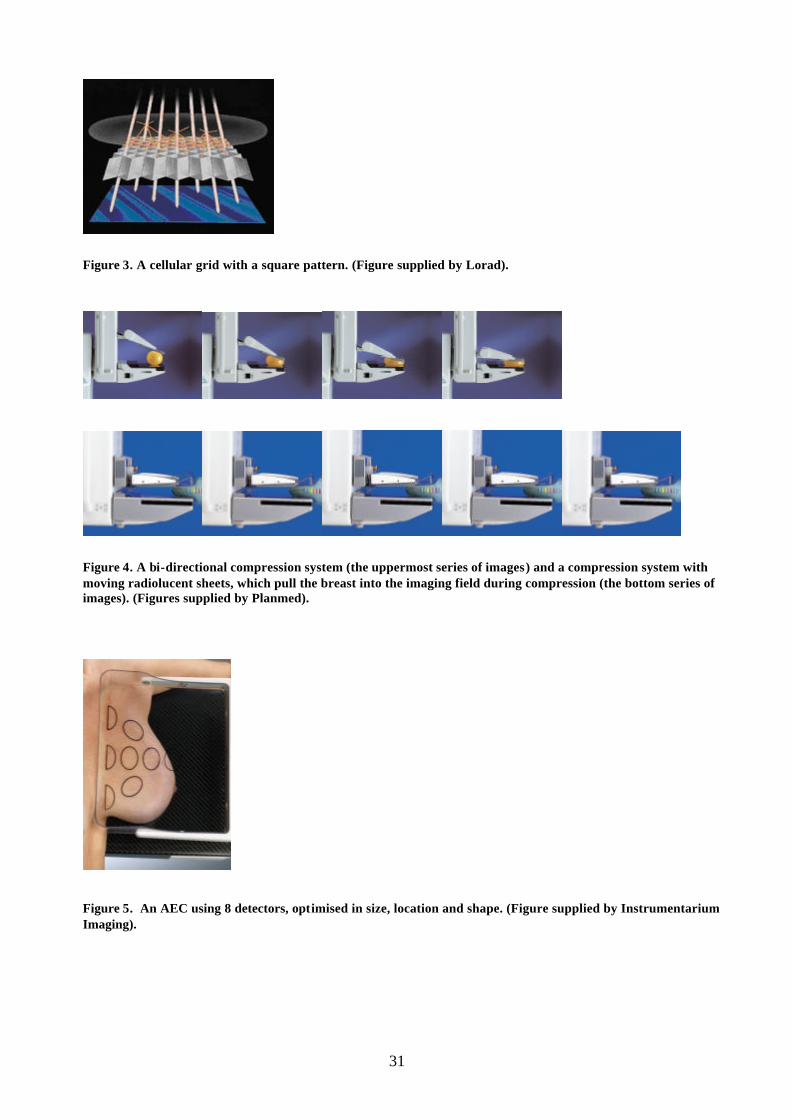
31
Figure 3. A cellular grid with a square pattern. (Figure supplied by Lorad).
Figure 4. A bi-directional compression system (the uppermost series of images) and a compression system with moving radiolucent sheets, which pull the breast into the imaging field during compression (the bottom series of images). (Figures supplied by Planmed).
Figure 5. An AEC using 8 detectors, optimised in size, location and shape. (Figure supplied by Instrumentarium Imaging).
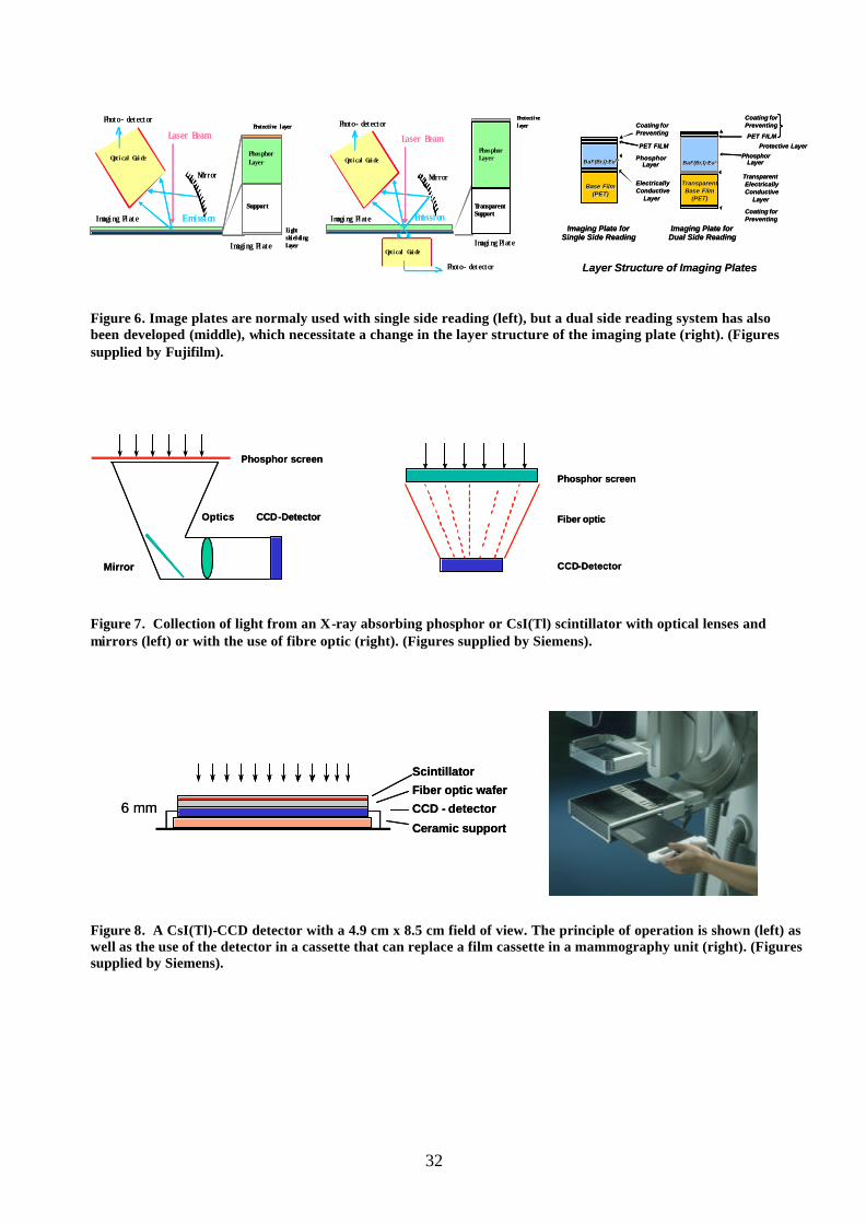
32
Figure 6. Image plates are normaly used with single side reading (left), but a dual side reading system has also been developed (middle), which necessitate a change in the layer structure of the imaging plate (right). (Figures supplied by Fujifilm).
Figure 7. Collection of light from an X-ray absorbing phosphor or CsI(Tl) scintillator with optical lenses and mirrors (left) or with the use of fibre optic (right). (Figures supplied by Siemens).
Figure 8. A CsI(Tl)-CCD detector with a 4.9 cm x 8.5 cm field of view. The principle of operation is shown (left) as well as the use of the detector in a cassette that can replace a film cassette in a mammography unit (right). (Figures supplied by Siemens).
CCD-Detector
Phosphor screen
Optics
Mirror
CCD-Detector
Phosphor screen
Optics
Mirror
Fiber optic
CCD-Detector
Phosphor screen
Fiber optic
CCD-Detector
Phosphor screen
Imaging Plate
Laser Beam
Mirror
Imaging Plate
Emission
Protective layerPhoto- detector
Optical Guide
Support
Phosphor Layer
Light shielding layer
Imaging Plate
Laser Beam
Mirror
Imaging Plate
Emission
Protective layerPhoto- detector
Optical Guide
Support
Phosphor Layer
Light shielding layer
Imaging Plate
Laser Beam
Mirror
Imaging Plate
Emission
Protective layer
Optical Guide
Photo- detector
Photo- detector
Optical Guide
Transparent Support
Phosphor Layer
Imaging Plate
Laser Beam
Mirror
Imaging Plate
Emission
Protective layer
Optical Guide
Photo- detector
Photo- detector
Optical Guide
Transparent Support
Phosphor Layer BaFBaF(Br,I):Eu(Br,I):Eu 2+2+
Protective LayerPET FILM
Imaging Plate forSingle Side Reading
Layer Structure of Imaging PlatesLayer Structure of Imaging Plates
Coating for Preventing
Coating for Preventing
PET FILM
BaFBaF(Br,I):Eu(Br,I):Eu2+2+Phosphor
Layer
Coating for Preventing
Base Film Base Film (PET)(PET)
TransparentTransparentBase Film Base Film
(PET)(PET)
Imaging Plate forDual Side Reading
ElectricallyConductive
Layer
PhosphorLayer
TransparentElectricallyConductive
Layer
BaFBaF(Br,I):Eu(Br,I):Eu 2+2+
Protective LayerPET FILM
Imaging Plate forSingle Side Reading
Layer Structure of Imaging PlatesLayer Structure of Imaging Plates
Coating for Preventing
Coating for Preventing
PET FILM
BaFBaF(Br,I):Eu(Br,I):Eu2+2+Phosphor
Layer
Coating for Preventing
Base Film Base Film (PET)(PET)
TransparentTransparentBase Film Base Film
(PET)(PET)
Imaging Plate forDual Side Reading
ElectricallyConductive
Layer
PhosphorLayer
TransparentElectricallyConductive
Layer
Scintillator
Fiber optic wafer
CCD - detector
Ceramic support
6 mm
Scintillator
Fiber optic wafer
CCD - detector
Ceramic support
6 mm

33
Figure 9. A mosaic detector with 3 x 4 detectors of CsI(Tl), each coupled to a CCD with fibre optic. (Figure supplied by Siemens).
Figure 10. Basic principles of a scanning system with a CsI(Tl)-scintillator coupled to a row of four CCDs in TDI mode (left). The detector is seen below the compression paddle (middle) and the complete mammography unit Fischer SenoScan is also seen (right). (Figures supplied by Siemens (left) and Fischer).
Figure 11. A CsI(Tl)-aSi detector, with the construction shown (left). The FFDM system GE Senographe 2000D with this detector is seen (middle) as well as the GE review workstation (right). (Figures supplied by General Electric).
X-ray scintillator
Fiber Optic Taper
CCD
tubeslot
linear array of CCDsin TDI mode
tubeslot
linear array of CCDsin TDI mode
linear array of CCDsin TDI mode
Amorphoussilicon arrayContacts
Glass substratAbsorber
CsI(Tl)
Contact leadsfor read-outelectronics
Amorphoussilicon arrayContacts
Glass substratAbsorber
CsI(Tl)
Contact leadsfor read-outelectronics

34
Figure 12. The aSe detector from Direct Radiography (left), which is used in the FFDM system Lorad Selenia. Also Siemens plan to use the detector in a FFDM system (right). (Figures supplied by Hologic and Siemens).
Figure 13. The basic detector principle of the Sectra Microdose Mammography, MDM, is shown (left). Clinically operational in Stockholm (right). The length of the aluminium strips is about 10 mm (Danielsson, 2001). (Figures supplied by Sectra-Mamea).
Figure 14. The principle of tomosynthesis (left), the Instrumentarium tomosynthesis mammography system Delta 32 TACT (middle) and an example of reconstructed images from that system (right). (Figures supplied by General Electric (left) and Instrumentarium Imaging).
300 µm50 µm

2002:01 SAR och utstrålad effekt för21 mobiltelefonerAvdelning för miljöövervakning och mätberedskap.Gert Anger 120 SEK
2002:02 Natural elemental concentrations andfluxes: their use as indicators of repository safetySKI-rapport 01:51
2002:03 SSI:s granskning av SKB:s FUD-program 2001Avddelningen för avfall och miljö.Björn Hedberg, Carl-Magnus Larsson, Anders Wiebert,Björn Dverstorp, Mikael Jensen, Maria Norden, TomasLöfgren, Erica Brewitz, John-Christer Lindhé och ÅsaPensjö.
2002:04 SSI’s review of SKB´s complement of theRD&D programme 1998Avdelningen för avfall och miljö.Mikael Jensen, Carl-Magnus Larsson, Anders Wiebert,Tomas Löfgren and Björn Hedberg.
2002:05 Patientdoser från röntgenundersökningari Sverige – uppföljning av åtgärderAvdelningen för personal- och patientstrålskydd.Helene Jönsson och Wolfram Leitz. 60 SEK
2002:06 Strålskyddskonsekvenser vid villaeldningmed 137Cs-kontaminerad vedAvdelning för miljöövervakning och mätberedskap.Hans Möre och Lynn Hubbard 60 SEK
2002:07 Säkerhets- och strålskyddsläget vid desvenska kärnkraftverken 2001
2002:08 Mammography – recent technicaldevelopments and their clinical potentialAvdelningen för personal- och patientstrålskydd.Bengt Hemdal, Ingvar Andersson, Anne Thilander Klang,Gert Bengtsson, Wolfram Leitz, Nils Bjurstam,Olof Jarlman and Sören Mattsson 80 SEK
SSI-rapporter 2002SSI reports 2002

Adress: Statens strålskyddsinstitut; S-17116 Stockholm;
Besöksadress: Karolinska sjukhusets område, Hus Z 5.
Telefon: 08-729 71 00, Fax: 08-729 71 08
Address: Swedish Radiation Protection Authority;
SE-17116 Stockholm; Sweden
Telephone: + 46 8-729 71 00, Fax: + 46 8-729 71 08
www.ssi.se
tatens strålskyddsinstitut, ssi, är en central tillsyns-
myndighet med uppgift att skydda människor, djur och miljö mot
skadlig verkan av strålning. SSI arbetar för en god avvägning mellan
risk och nytta med strålning, och för att öka kunskaperna om strål-
ning, så att individens risk begränsas.
SSI sätter gränser för stråldoser till allmänheten och till dem som
arbetar med strålning, utfärdar föreskrifter och kontrollerar att de efter-
levs, bland annat genom inspektioner. Myndigheten informerar, utbildar
och ger råd för att öka kunskaperna om strålning. SSI bedriver också
egen forskning och stöder forskning vid universitet och högskolor.
Myndigheten medverkar i det internationella strålskyddssam-
arbetet. Därigenom bidrar SSI till förbättringar av strålskyddet i främst
Baltikum och Ryssland. SSI håller beredskap dygnet runt mot olyckor
med strålning. En tidig varning om olyckor fås genom svenska och
utländska mätstationer och genom internationella varnings- och in-
formationssystem.
SSI har idag ca 110 anställda och är beläget i Stockholm.
the swedish radiation protection authority (ssi) is a
government authority with the task of protecting mankind and the
living environment from the harmful effects of radiation. SSI ensures
that the risks and benefits inherent to radiation and its use are
compared and evaluated, and that knowledge regarding radiation
continues to develop, so that the risk to individuals is minimised.
SSI decides the dose limits for the public and for workers exposed
to radiation, and issues regulations that, through inspections, it ensures
are being followed. SSI provides information, education, and advice,
carries out research and administers external research projects.
SSI participates on a national and international level in the field
of radiation protection. As a part of that participation, SSI contributes
towards improvements in radiation protection standards in the for-
mer Soviet states.
SSI is responsible for co-ordinating activities in Sweden should an
accident involving radiation occur. Its resources can be called upon
at any time of the day or night. If an accident occurs, a special
emergency preparedness organisation is activated. Early notification
of emergencies is obtained from automatic alarm monitoring stations
in Sweden and abroad, and through international and bilateral
agreements on early warning and information.
SSI has 110 employees and is situated in Stockholm.
S