Embed Size (px)
Citation preview
TECHNICAL DATASHEET
CliQ III DIN Rail Power Supply 24V 240W 1 Phase / DRP-24V240W1C□N
All parameters are specified at 25°C ambient and AC input unless otherwise indicated. www.DeltaPSU.com (June 2019, Rev. 02)
1
Highlights & Features • Universal AC input voltage range • Built-in constant current circuit for charging application • High efficiency of up to 94% at 230Vac • Power Boost of 150% for 5 seconds • Advanced Power Boost (APB) of 200% for 50ms • SEMI F47 compliance at 120Vac • Extreme low temperature cold start at -40°C • Built-in DC OK Contact and LED indicator for DC OK • Conformal coating on PCBA to protect against common dust
and chemical pollutants
Safety Standards
CB Certified for worldwide use
Model Number: DRP-24V240W1C☐N Unit Weight: 0.84 kg (1.85 lb) Dimensions (L x W x D): 124 x 60 x 117 mm
(4.88 x 2.36 x 4.61 inch) General Description The CliQ III series of DIN rail power supply series is designed with high power density and intelligent overload protection features. All the models in the series are encased in rugged yet lightweight and full corrosion resistant aluminium casing. The single output with universal input design offers overcurrent protection in constant current mode which makes the series suitable for charging application. Like the rest of the CliQ family of products, conformal coating is applied on the PCBAs to protect against common dust and chemical pollutant often found in harsh industrial environment. Delta CliQ III DIN rail power supply series features built-in Power Boost of 150% for 5 seconds. Such feature enables reserve power to be always available for reliable startup of loads with high inrush current without the need of a more expensive power supply at higher power rating. Model Information CliQ III DIN Rail Power Supply Model Number Input Voltage Range Rated Output Voltage Rated Output Current DRP-24V240W1C☐N 88-264Vac
24Vdc 10.0A
Model Numbering
DR P – 24V 240W 1 C □ N DIN Rail Power Supply Output Voltage Output Power Single Phase CliQ III Input Voltage
A – AC Input B – AC & DC Input
N – Metal Case, without Class I, Div 2 and ATEX approvals
TECHNICAL DATASHEET
CliQ III DIN Rail Power Supply 24V 240W 1 Phase / DRP-24V240W1C□N
All parameters are specified at 25°C ambient and AC input unless otherwise indicated. www.DeltaPSU.com (June 2019, Rev. 02)
2
Specifications Input Ratings / Characteristics Nominal Input Voltage 100-240Vac
Applicable for TN-, TT and IT mains networks
Input Voltage Range 100-264Vac Continuously operating 88-100Vac With power de-rating. Refer to Fig. 6 on
page 11. Input Frequency Nom. 50-60Hz Range: 47-63Hz DC Input Voltage Range (For DRP-24V240W1CBN)
100-375Vdc Continuously operating, with safety approval according to IEC/EN/UL 60950-1.
88-100Vdc With power de-rating. Refer to Fig. 7 on page 11.
115Vac 230Vac Input Current Typ. 2.27A 1.19A At 24V, 10A. Refer to Fig. 1 on page 3. Max. 2.60A 1.30A At 24V, 10A. Efficiency Typ. 92.70% 94.48% At 24V, 10A. Refer to Fig. 2 on page 3. Min. 91.00% 93.00% At 24V, 10A. Average Efficiency Typ. 91.52% 92.56% At 24V, 2.5A (25%), 5.0A (50%),
Min. 91.00% 92.00% 7.5A (75%), 10.0A (100%)
Max Power Dissipation Typ. 3.54W 2.90W At 24V, 0A. Refer to Fig. 3 on page 3. Max. 6.0W 6.0W At 24V, 0A. Typ. 18.97W 14.05W At 24V, 10A. Refer to Fig. 3 on page 3. Max. 21.0W 16.0W At 24V, 10A. Max Inrush Current (Cold Start) Typ.
11.0A 24.4A At 24V, 10A.
Max. 33A 65A Max Inrush Energy (Cold Start) Max. 1A2s Power Factor Typ. 0.99 0.93 At 24V, 10A. Refer to Fig. 4 on page 3. Min. 0.99 0.93 At 24V, 10A. Leakage Current (Enclosure to Neutral)
< 0.25mA / 0.80mA < 0.38mA / 1.00mA < 0.74mA / 2.00mA
110Vac, 50Hz, TN/TT system / IT system 132Vac, 50Hz, TN/TT system / IT system 264Vac, 50Hz, TN/TT system / IT system
TECHNICAL DATASHEET
CliQ III DIN Rail Power Supply 24V 240W 1 Phase / DRP-24V240W1C□N
All parameters are specified at 25°C ambient and AC input unless otherwise indicated. www.DeltaPSU.com (June 2019, Rev. 02)
3
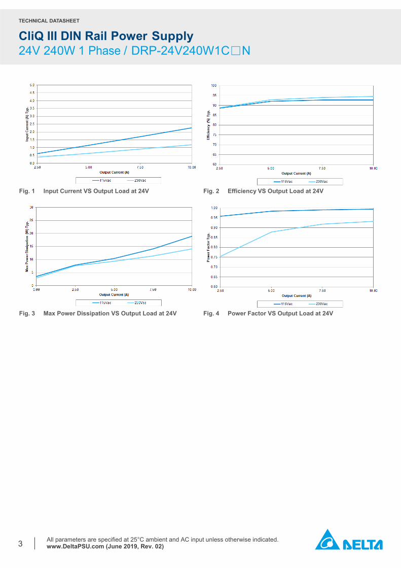
Fig. 1 Input Current VS Output Load at 24V Fig. 2 Efficiency VS Output Load at 24V
Fig. 3 Max Power Dissipation VS Output Load at 24V Fig. 4 Power Factor VS Output Load at 24V
TECHNICAL DATASHEET
CliQ III DIN Rail Power Supply 24V 240W 1 Phase / DRP-24V240W1C□N
All parameters are specified at 25°C ambient and AC input unless otherwise indicated. www.DeltaPSU.com (June 2019, Rev. 02)
4
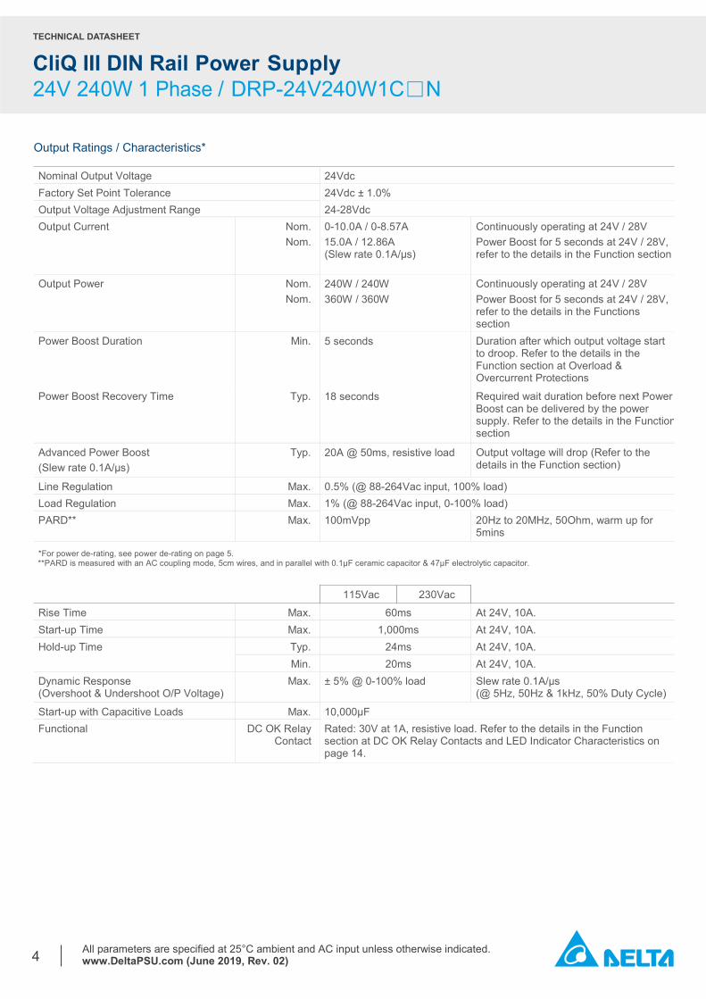
Output Ratings / Characteristics* Nominal Output Voltage 24Vdc Factory Set Point Tolerance 24Vdc ± 1.0% Output Voltage Adjustment Range 24-28Vdc Output Current Nom.
Nom. 0-10.0A / 0-8.57A 15.0A / 12.86A (Slew rate 0.1A/µs)
Continuously operating at 24V / 28V Power Boost for 5 seconds at 24V / 28V, refer to the details in the Function section
Output Power Nom. Nom.
240W / 240W 360W / 360W
Continuously operating at 24V / 28V Power Boost for 5 seconds at 24V / 28V, refer to the details in the Functions section
Power Boost Duration Min. 5 seconds Duration after which output voltage start to droop. Refer to the details in the Function section at Overload & Overcurrent Protections
Power Boost Recovery Time Typ. 18 seconds Required wait duration before next Power Boost can be delivered by the power supply. Refer to the details in the Function section
Advanced Power Boost (Slew rate 0.1A/µs)
Typ. 20A @ 50ms, resistive load Output voltage will drop (Refer to the details in the Function section)
Line Regulation Max. 0.5% (@ 88-264Vac input, 100% load) Load Regulation Max. 1% (@ 88-264Vac input, 0-100% load) PARD** Max. 100mVpp 20Hz to 20MHz, 50Ohm, warm up for
5mins
*For power de-rating, see power de-rating on page 5. **PARD is measured with an AC coupling mode, 5cm wires, and in parallel with 0.1μF ceramic capacitor & 47μF electrolytic capacitor.
115Vac 230Vac Rise Time Max. 60ms At 24V, 10A. Start-up Time Max. 1,000ms At 24V, 10A. Hold-up Time Typ. 24ms At 24V, 10A. Min. 20ms At 24V, 10A. Dynamic Response (Overshoot & Undershoot O/P Voltage)
Max. ± 5% @ 0-100% load Slew rate 0.1A/µs (@ 5Hz, 50Hz & 1kHz, 50% Duty Cycle)
Start-up with Capacitive Loads Max. 10,000µF Functional DC OK Relay
Contact Rated: 30V at 1A, resistive load. Refer to the details in the Function section at DC OK Relay Contacts and LED Indicator Characteristics on page 14.
TECHNICAL DATASHEET
CliQ III DIN Rail Power Supply 24V 240W 1 Phase / DRP-24V240W1C□N
All parameters are specified at 25°C ambient and AC input unless otherwise indicated. www.DeltaPSU.com (June 2019, Rev. 02)
5
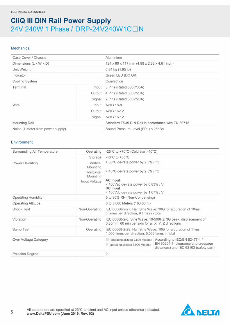
Mechanical Case Cover / Chassis Aluminium
Dimensions (L x W x D) 124 x 60 x 117 mm (4.88 x 2.36 x 4.61 inch)
Unit Weight 0.84 kg (1.85 lb) Indicator Green LED (DC OK)
Cooling System Convection
Terminal Input 3 Pins (Rated 600V/35A)
Output 4 Pins (Rated 300V/28A)
Signal 2 Pins (Rated 300V/28A)
Wire Input AWG 18-8
Output AWG 16-12
Signal AWG 16-12
Mounting Rail Standard TS35 DIN Rail in accordance with EN 60715
Noise (1 Meter from power supply) Sound Pressure Level (SPL) < 25dBA Environment Surrounding Air Temperature Operating -25°C to +70°C (Cold start -40°C) Storage -40°C to +85°C Power De-rating Vertical
Mounting > 60°C de-rate power by 2.5% / °C
Horizontal Mounting
> 40°C de-rate power by 2.5% / °C
Input Voltage AC input < 100Vac de-rate power by 0.83% / V DC input < 100Vdc de-rate power by 1.67% / V
Operating Humidity 5 to 95% RH (Non-Condensing) Operating Altitude 0 to 5,000 Meters (16,400 ft.)
Shock Test Non-Operating IEC 60068-2-27, Half Sine Wave: 30G for a duration of 18ms; 3 times per direction, 9 times in total
Vibration Non-Operating IEC 60068-2-6, Sine Wave: 10-500Hz; 3G peak; displacement of 0.35mm; 60 min per axis for all X, Y, Z directions
Bump Test Operating IEC 60068-2-29, Half Sine Wave: 10G for a duration of 11ms, 1,000 times per direction, 6,000 times in total
Over Voltage Category III (operating altitude 2,500 Meters) II (operating altitude 5,000 Meters)
According to IEC/EN 62477-1 / EN 60204-1 (clearance and creepage distances) and IEC 62103 (safety part)
Pollution Degree 2
TECHNICAL DATASHEET
CliQ III DIN Rail Power Supply 24V 240W 1 Phase / DRP-24V240W1C□N
All parameters are specified at 25°C ambient and AC input unless otherwise indicated. www.DeltaPSU.com (June 2019, Rev. 02)
6
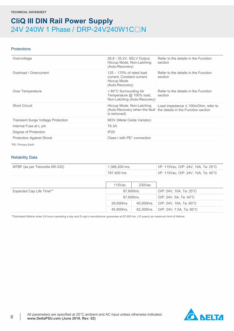
Protections Overvoltage 28.8 - 35.2V, SELV Output,
Hiccup Mode, Non-Latching (Auto-Recovery)
Refer to the details in the Function section
Overload / Overcurrent 125 – 170% of rated load current, Constant current, Hiccup Mode (Auto-Recovery)
Refer to the details in the Function section
Over Temperature < 80°C Surrounding Air Temperature @ 100% load, Non-Latching (Auto-Recovery)
Refer to the details in the Function section
Short Circuit Hiccup Mode, Non-Latching (Auto-Recovery when the fault is removed)
Load impedance ≤ 100mOhm, refer to the details in the Function section
Transient Surge Voltage Protection MOV (Metal Oxide Varistor) Internal Fuse at L pin T6.3A Degree of Protection IP20 Protection Against Shock Class I with PE* connection
*PE: Primary Earth Reliability Data MTBF (as per Telcordia SR-332) 1,366,200 hrs. I/P: 115Vac, O/P: 24V, 10A, Ta: 25°C
767,400 hrs. I/P: 115Vac, O/P: 24V, 10A, Ta: 40°C
115Vac 230Vac
Expected Cap Life Time** 87,600hrs. O/P: 24V, 10A, Ta: 25°C
87,600hrs. O/P: 24V, 5A, Ta: 40°C
29,000hrs. 40,000hrs. O/P: 24V, 10A, Ta: 60°C
45,900hrs. 62,300hrs. O/P: 24V, 7.5A, Ta: 60°C
**Estimated lifetime when 24 hours operating a day and E-cap’s manufacturer guarantee at 87,600 hrs. (10 years) as maximum limit of lifetime.
TECHNICAL DATASHEET
CliQ III DIN Rail Power Supply 24V 240W 1 Phase / DRP-24V240W1C□N
All parameters are specified at 25°C ambient and AC input unless otherwise indicated. www.DeltaPSU.com (June 2019, Rev. 02)
7
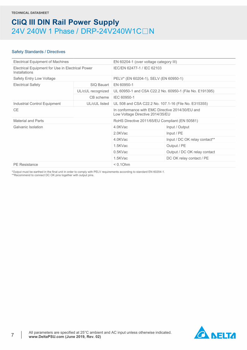
Safety Standards / Directives Electrical Equipment of Machines EN 60204-1 (over voltage category III) Electrical Equipment for Use in Electrical Power Installations
IEC/EN 62477-1 / IEC 62103
Safety Entry Low Voltage PELV* (EN 60204-1), SELV (EN 60950-1) Electrical Safety SIQ Bauart
EN 60950-1 UL/cUL recognized
UL 60950-1 and CSA C22.2 No. 60950-1 (File No. E191395) CB scheme IEC 60950-1
Industrial Control Equipment UL/cUL listed
UL 508 and CSA C22.2 No. 107.1-16 (File No. E315355) CE In conformance with EMC Directive 2014/30/EU and Low Voltage Directive 2014/35/EU
Material and Parts RoHS Directive 2011/65/EU Compliant (EN 50581) Galvanic Isolation 4.0KVac Input / Output 2.0KVac Input / PE 4.0KVac Input / DC OK relay contact** 1.5KVac Output / PE 0.5KVac Output / DC OK relay contact 1.5KVac DC OK relay contact / PE PE Resistance < 0.1Ohm
*Output must be earthed in the final unit in order to comply with PELV requirements according to standard EN 60204-1. **Recommend to connect DC OK pins together with output pins.
TECHNICAL DATASHEET
CliQ III DIN Rail Power Supply 24V 240W 1 Phase / DRP-24V240W1C□N
All parameters are specified at 25°C ambient and AC input unless otherwise indicated. www.DeltaPSU.com (June 2019, Rev. 02)
8
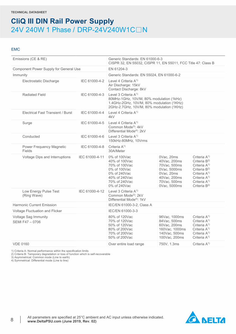
EMC Emissions (CE & RE) Generic Standards: EN 61000-6-3
CISPR 32, EN 55032, CISPR 11, EN 55011, FCC Title 47: Class B Component Power Supply for General Use EN 61204-3 Immunity Generic Standards: EN 55024, EN 61000-6-2
Electrostatic Discharge IEC 61000-4-2 Level 4 Criteria A1) Air Discharge: 15kV Contact Discharge: 8kV
Radiated Field IEC 61000-4-3 Level 3 Criteria A1) 80MHz-1GHz, 10V/M, 80% modulation (1kHz) 1.4GHz-2GHz, 10V/M, 80% modulation (1KHz) 2GHz-2.7GHz, 10V/M, 80% modulation (1KHz)
Electrical Fast Transient / Burst IEC 61000-4-4 Level 4 Criteria A1) 4kV
Surge IEC 61000-4-5 Level 4 Criteria A1) Common Mode3): 4kV Differential Mode4): 2kV
Conducted IEC 61000-4-6 Level 3 Criteria A1) 150kHz-80MHz, 10Vrms
Power Frequency Magnetic Fields
IEC 61000-4-8 Criteria A1) 30A/Meter
Voltage Dips and Interruptions IEC 61000-4-11 0% of 100Vac 40% of 100Vac 70% of 100Vac 0% of 100Vac 0% of 240Vac 40% of 240Vac 70% of 240Vac 0% of 240Vac
0Vac, 20ms 40Vac, 200ms 70Vac, 500ms 0Vac, 5000ms 0Vac, 20ms 40Vac, 200ms 70Vac, 500ms 0Vac, 5000ms
Criteria A1) Criteria B2) Criteria A1) Criteria B2) Criteria A1) Criteria A1) Criteria A1) Criteria B2)
Low Energy Pulse Test (Ring Wave)
IEC 61000-4-12 Level 3 Criteria A1) Common Mode3): 2kV Differential Mode4): 1kV
Harmonic Current Emission IEC/EN 61000-3-2, Class A Voltage Fluctuation and Flicker IEC/EN 61000-3-3 Voltage Sag Immunity SEMI F47 – 0706
80% of 120Vac 70% of 120Vac 50% of 120Vac 80% of 200Vac 70% of 200Vac 50% of 200Vac
96Vac, 1000ms 84Vac, 500ms 60Vac, 200ms 160Vac, 1000ms 140Vac, 500ms 100Vac, 200ms
Criteria A1) Criteria A1) Criteria A1)
Criteria A1) Criteria A1) Criteria A1)
VDE 0160 Over entire load range 750V, 1.3ms Criteria A1) 1) Criteria A: Normal performance within the specification limits
2) Criteria B: Temporary degradation or loss of function which is self-recoverable 3) Asymmetrical: Common mode (Line to earth) 4) Symmetrical: Differential mode (Line to line)
TECHNICAL DATASHEET
CliQ III DIN Rail Power Supply 24V 240W 1 Phase / DRP-24V240W1C□N
All parameters are specified at 25°C ambient and AC input unless otherwise indicated. www.DeltaPSU.com (June 2019, Rev. 02)
9
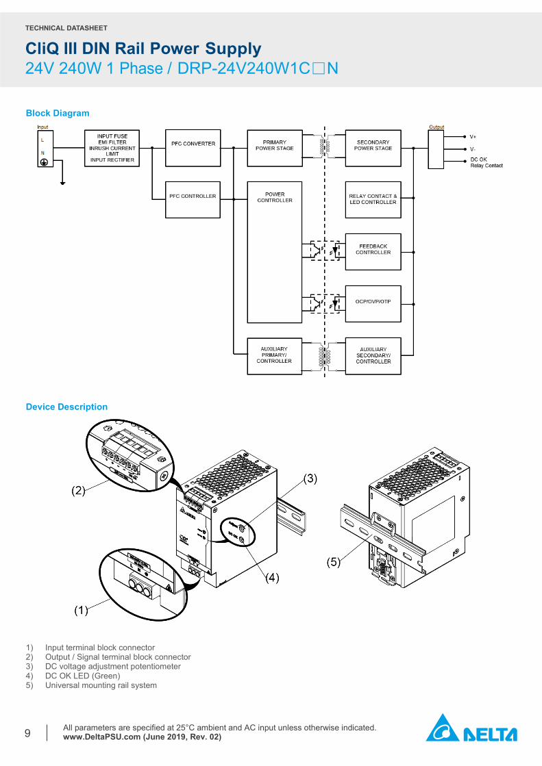
Block Diagram
Device Description
1) Input terminal block connector 2) Output / Signal terminal block connector 3) DC voltage adjustment potentiometer 4) DC OK LED (Green) 5) Universal mounting rail system
TECHNICAL DATASHEET
CliQ III DIN Rail Power Supply 24V 240W 1 Phase / DRP-24V240W1C□N
All parameters are specified at 25°C ambient and AC input unless otherwise indicated. www.DeltaPSU.com (June 2019, Rev. 02)
10
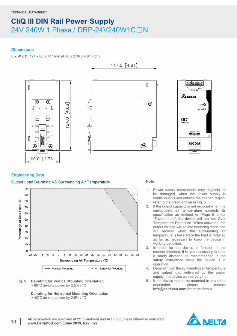
Dimensions L x W x D: 124 x 60 x 117 mm (4.88 x 2.36 x 4.61 inch)
Engineering Data Output Load De-rating VS Surrounding Air Temperature
Note 1. Power supply components may degrade, or
be damaged, when the power supply is continuously used outside the shaded region, refer to the graph shown in Fig. 5.
2. If the output capacity is not reduced when the surrounding air temperature exceeds its specification as defined on Page 5 under “Environment”, the device will run into Over Temperature Protection. When activated, the output voltage will go into bouncing mode and will recover when the surrounding air temperature is lowered or the load is reduced as far as necessary to keep the device in working condition.
3. In order for the device to function in the manner intended, it is also necessary to keep a safety distance as recommended in the safety instructions while the device is in operation.
4. Depending on the surrounding air temperature and output load delivered by the power supply, the device can be very hot!
5. If the device has to be mounted in any other orientation, please contact [email protected] for more details.
Fig. 5 De-rating for Vertical Mounting Orientation > 60°C de-rate power by 2.5% / °C
De-rating for Horizontal Mounting Orientation > 40°C de-rate power by 2.5% / °C
TECHNICAL DATASHEET
CliQ III DIN Rail Power Supply 24V 240W 1 Phase / DRP-24V240W1C□N
All parameters are specified at 25°C ambient and AC input unless otherwise indicated. www.DeltaPSU.com (June 2019, Rev. 02)
11
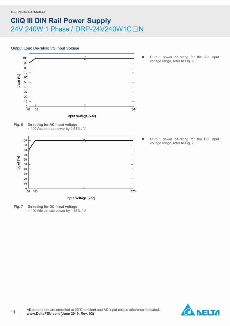
Output Load De-rating VS Input Voltage
Output power de-rating for the AC input voltage range, refer to Fig. 6.
Fig. 6 De-rating for AC input voltage < 100Vac de-rate power by 0.83% / V
Fig. 7 De-rating for DC input voltage < 100Vdc de-rate power by 1.67% / V
Output power de-rating for the DC input voltage range, refer to Fig. 7.
TECHNICAL DATASHEET
CliQ III DIN Rail Power Supply 24V 240W 1 Phase / DRP-24V240W1C□N
All parameters are specified at 25°C ambient and AC input unless otherwise indicated. www.DeltaPSU.com (June 2019, Rev. 02)
12
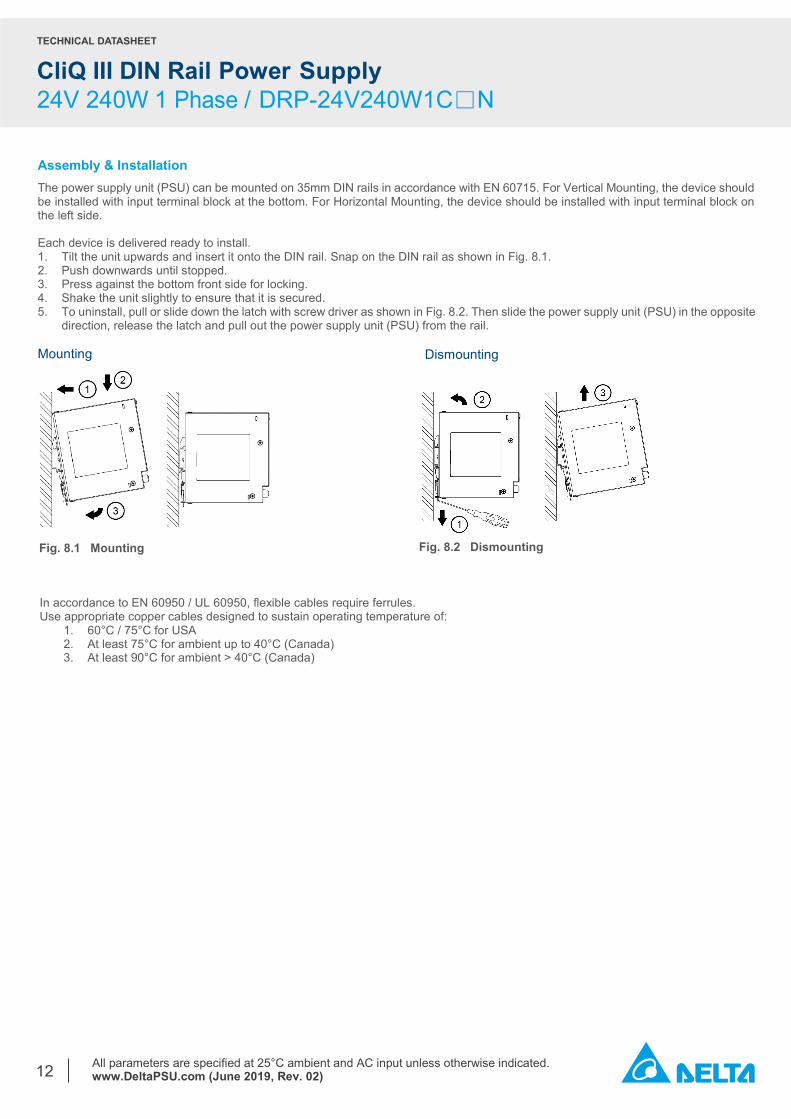
Assembly & Installation The power supply unit (PSU) can be mounted on 35mm DIN rails in accordance with EN 60715. For Vertical Mounting, the device should be installed with input terminal block at the bottom. For Horizontal Mounting, the device should be installed with input terminal block on the left side. Each device is delivered ready to install. 1. Tilt the unit upwards and insert it onto the DIN rail. Snap on the DIN rail as shown in Fig. 8.1. 2. Push downwards until stopped. 3. Press against the bottom front side for locking. 4. Shake the unit slightly to ensure that it is secured. 5. To uninstall, pull or slide down the latch with screw driver as shown in Fig. 8.2. Then slide the power supply unit (PSU) in the opposite
direction, release the latch and pull out the power supply unit (PSU) from the rail. Mounting
Fig. 8.2 Dismounting
Fig. 8.1 Mounting
In accordance to EN 60950 / UL 60950, flexible cables require ferrules. Use appropriate copper cables designed to sustain operating temperature of:
1. 60°C / 75°C for USA 2. At least 75°C for ambient up to 40°C (Canada) 3. At least 90°C for ambient > 40°C (Canada)
Dismounting
TECHNICAL DATASHEET
CliQ III DIN Rail Power Supply 24V 240W 1 Phase / DRP-24V240W1C□N
All parameters are specified at 25°C ambient and AC input unless otherwise indicated. www.DeltaPSU.com (June 2019, Rev. 02)
13
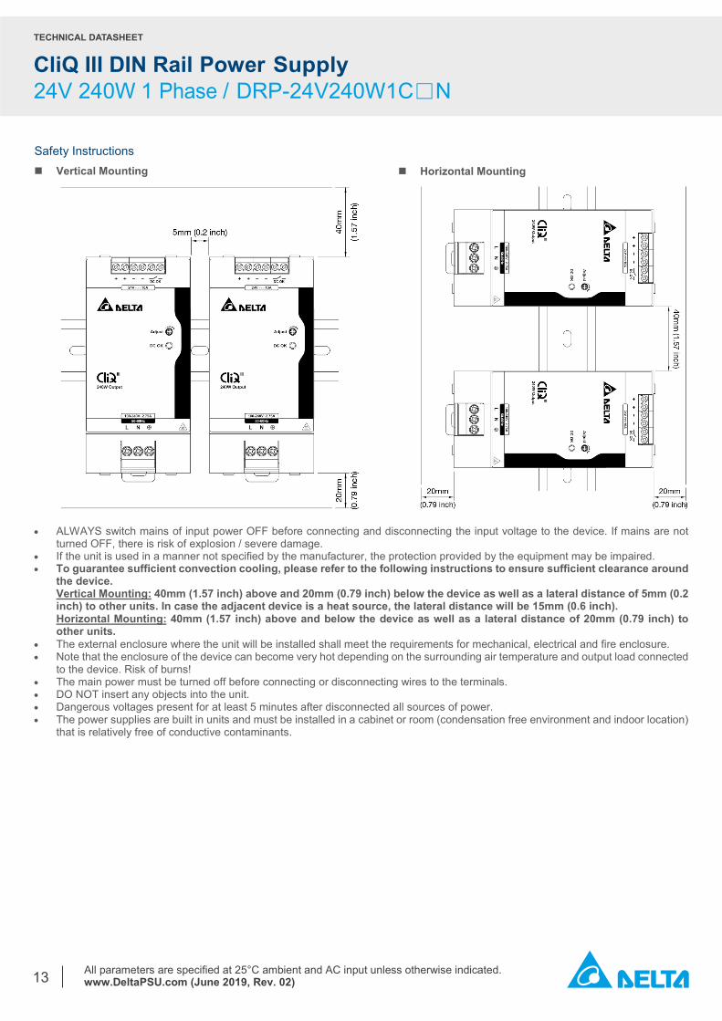
Safety Instructions Vertical Mounting
• ALWAYS switch mains of input power OFF before connecting and disconnecting the input voltage to the device. If mains are not turned OFF, there is risk of explosion / severe damage.
• If the unit is used in a manner not specified by the manufacturer, the protection provided by the equipment may be impaired. • To guarantee sufficient convection cooling, please refer to the following instructions to ensure sufficient clearance around
the device. Vertical Mounting: 40mm (1.57 inch) above and 20mm (0.79 inch) below the device as well as a lateral distance of 5mm (0.2 inch) to other units. In case the adjacent device is a heat source, the lateral distance will be 15mm (0.6 inch). Horizontal Mounting: 40mm (1.57 inch) above and below the device as well as a lateral distance of 20mm (0.79 inch) to other units.
• The external enclosure where the unit will be installed shall meet the requirements for mechanical, electrical and fire enclosure. • Note that the enclosure of the device can become very hot depending on the surrounding air temperature and output load connected
to the device. Risk of burns! • The main power must be turned off before connecting or disconnecting wires to the terminals. • DO NOT insert any objects into the unit. • Dangerous voltages present for at least 5 minutes after disconnected all sources of power. • The power supplies are built in units and must be installed in a cabinet or room (condensation free environment and indoor location)
that is relatively free of conductive contaminants.
Horizontal Mounting
TECHNICAL DATASHEET
CliQ III DIN Rail Power Supply 24V 240W 1 Phase / DRP-24V240W1C□N
All parameters are specified at 25°C ambient and AC input unless otherwise indicated. www.DeltaPSU.com (June 2019, Rev. 02)
14
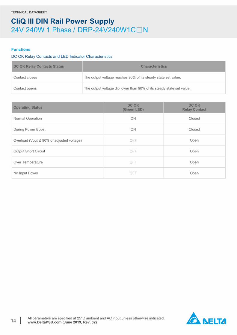
Functions DC OK Relay Contacts and LED Indicator Characteristics
DC OK Relay Contacts Status Characteristics
Contact closes The output voltage reaches 90% of its steady state set value.
Contact opens The output voltage dip lower than 90% of its steady state set value.
Operating Status DC OK (Green LED)
DC OK Relay Contact
Normal Operation ON Closed
During Power Boost ON Closed
Overload (Vout ≤ 90% of adjusted voltage) OFF Open
Output Short Circuit OFF Open
Over Temperature OFF Open
No Input Power OFF Open
TECHNICAL DATASHEET
CliQ III DIN Rail Power Supply 24V 240W 1 Phase / DRP-24V240W1C□N
All parameters are specified at 25°C ambient and AC input unless otherwise indicated. www.DeltaPSU.com (June 2019, Rev. 02)
15
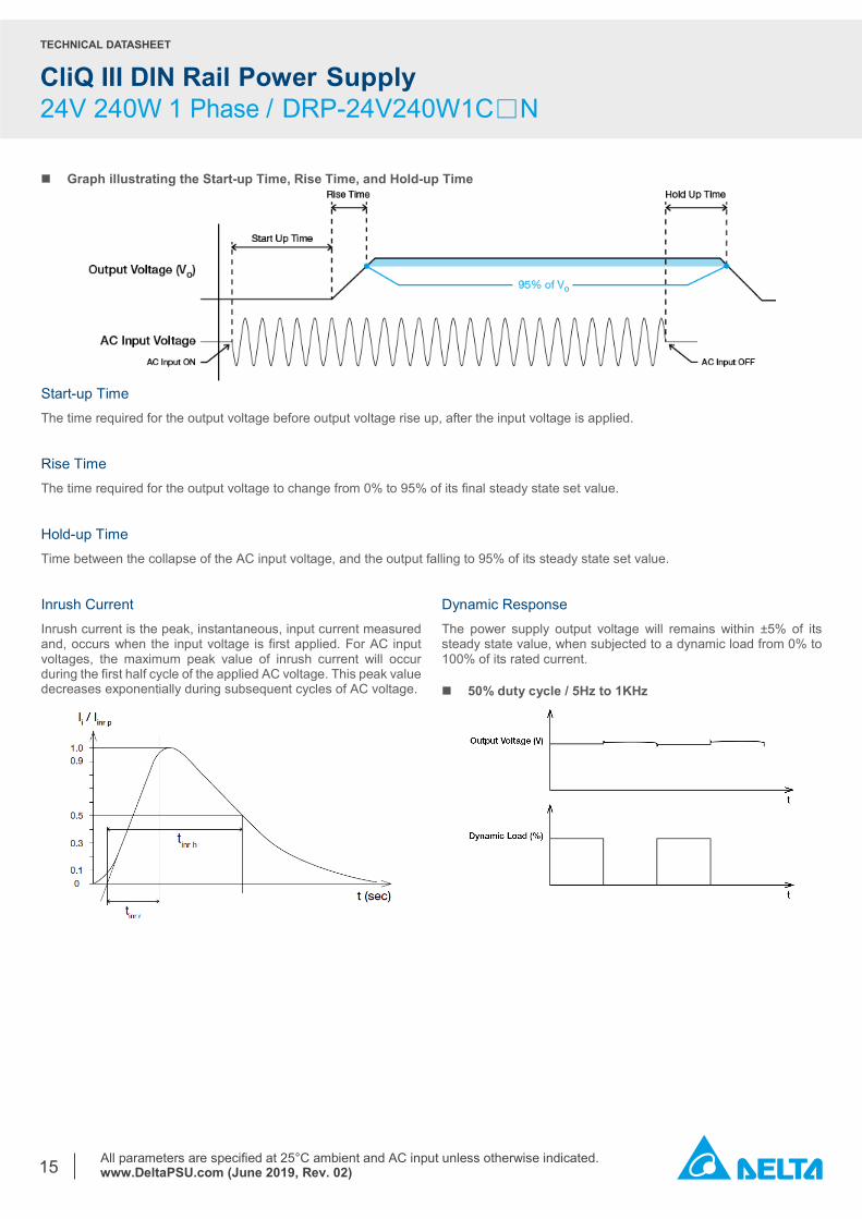
Graph illustrating the Start-up Time, Rise Time, and Hold-up Time
Start-up Time The time required for the output voltage before output voltage rise up, after the input voltage is applied. Rise Time The time required for the output voltage to change from 0% to 95% of its final steady state set value. Hold-up Time Time between the collapse of the AC input voltage, and the output falling to 95% of its steady state set value. Inrush Current Inrush current is the peak, instantaneous, input current measured and, occurs when the input voltage is first applied. For AC input voltages, the maximum peak value of inrush current will occur during the first half cycle of the applied AC voltage. This peak value decreases exponentially during subsequent cycles of AC voltage.
Dynamic Response The power supply output voltage will remains within ±5% of its steady state value, when subjected to a dynamic load from 0% to 100% of its rated current.
50% duty cycle / 5Hz to 1KHz
TECHNICAL DATASHEET
CliQ III DIN Rail Power Supply 24V 240W 1 Phase / DRP-24V240W1C□N
All parameters are specified at 25°C ambient and AC input unless otherwise indicated. www.DeltaPSU.com (June 2019, Rev. 02)
16
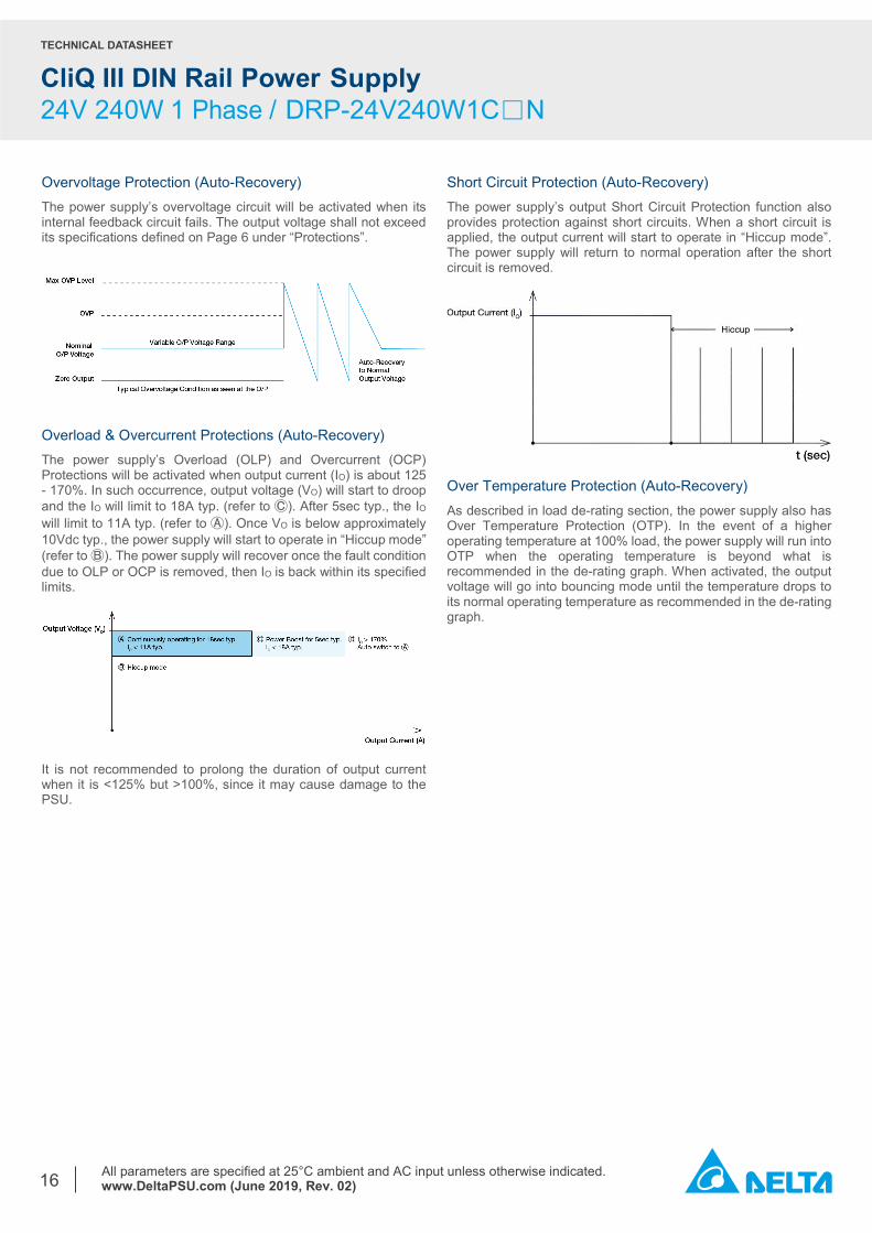
Overvoltage Protection (Auto-Recovery) The power supply’s overvoltage circuit will be activated when its internal feedback circuit fails. The output voltage shall not exceed its specifications defined on Page 6 under “Protections”.
Overload & Overcurrent Protections (Auto-Recovery) The power supply’s Overload (OLP) and Overcurrent (OCP) Protections will be activated when output current (IO) is about 125 - 170%. In such occurrence, output voltage (VO) will start to droop and the IO will limit to 18A typ. (refer to Ⓒ). After 5sec typ., the IO will limit to 11A typ. (refer to Ⓐ). Once VO is below approximately 10Vdc typ., the power supply will start to operate in “Hiccup mode” (refer to Ⓑ). The power supply will recover once the fault condition due to OLP or OCP is removed, then IO is back within its specified limits.
It is not recommended to prolong the duration of output current when it is <125% but >100%, since it may cause damage to the PSU.
Short Circuit Protection (Auto-Recovery) The power supply’s output Short Circuit Protection function also provides protection against short circuits. When a short circuit is applied, the output current will start to operate in “Hiccup mode”. The power supply will return to normal operation after the short circuit is removed.
Over Temperature Protection (Auto-Recovery) As described in load de-rating section, the power supply also has Over Temperature Protection (OTP). In the event of a higher operating temperature at 100% load, the power supply will run into OTP when the operating temperature is beyond what is recommended in the de-rating graph. When activated, the output voltage will go into bouncing mode until the temperature drops to its normal operating temperature as recommended in the de-rating graph.
TECHNICAL DATASHEET
CliQ III DIN Rail Power Supply 24V 240W 1 Phase / DRP-24V240W1C□N
All parameters are specified at 25°C ambient and AC input unless otherwise indicated. www.DeltaPSU.com (June 2019, Rev. 02)
17
Power Boost
𝐷𝐷𝐷𝐷𝐷𝐷𝐷𝐷 𝑐𝑐𝐷𝐷𝑐𝑐𝑐𝑐𝑐𝑐 (%) = 𝑇𝑇𝑃𝑃
𝑇𝑇𝑇𝑇𝐷𝐷𝑇𝑇𝑐𝑐 𝑇𝑇𝑇𝑇𝑇𝑇𝑐𝑐
𝐴𝐴𝐴𝐴𝑐𝑐𝐴𝐴𝑇𝑇𝐴𝐴𝑐𝑐 𝑂𝑂𝐷𝐷𝐷𝐷𝑂𝑂𝐷𝐷𝐷𝐷 𝑃𝑃𝑇𝑇𝑃𝑃𝑐𝑐𝐴𝐴 (𝑃𝑃𝐴𝐴𝐴𝐴𝐴𝐴) =(𝑃𝑃𝑇𝑇𝑃𝑃𝑐𝑐𝐴𝐴 𝐵𝐵𝑇𝑇𝑇𝑇𝐵𝐵𝐷𝐷 × 𝑇𝑇𝑃𝑃) + (𝑁𝑁𝑇𝑇𝑁𝑁-𝑃𝑃𝑐𝑐𝑇𝑇𝑃𝑃 𝑃𝑃𝑇𝑇𝑃𝑃𝑐𝑐𝐴𝐴 × 𝑇𝑇𝑁𝑁)
𝑇𝑇𝑇𝑇𝐷𝐷𝑇𝑇𝑐𝑐 𝑇𝑇𝑇𝑇𝑇𝑇𝑐𝑐
OR
𝑁𝑁𝑇𝑇𝑁𝑁-𝑃𝑃𝑐𝑐𝑇𝑇𝑃𝑃 𝑃𝑃𝑇𝑇𝑃𝑃𝑐𝑐𝐴𝐴 =�𝑃𝑃𝐴𝐴𝐴𝐴𝐴𝐴 × 𝑇𝑇𝑇𝑇𝐷𝐷𝑇𝑇𝑐𝑐 𝑇𝑇𝑇𝑇𝑇𝑇𝑐𝑐� − (𝑃𝑃𝑇𝑇𝑃𝑃𝑐𝑐𝐴𝐴 𝐵𝐵𝑇𝑇𝑇𝑇𝐵𝐵𝐷𝐷 × 𝑇𝑇𝑃𝑃)
𝑇𝑇𝑁𝑁
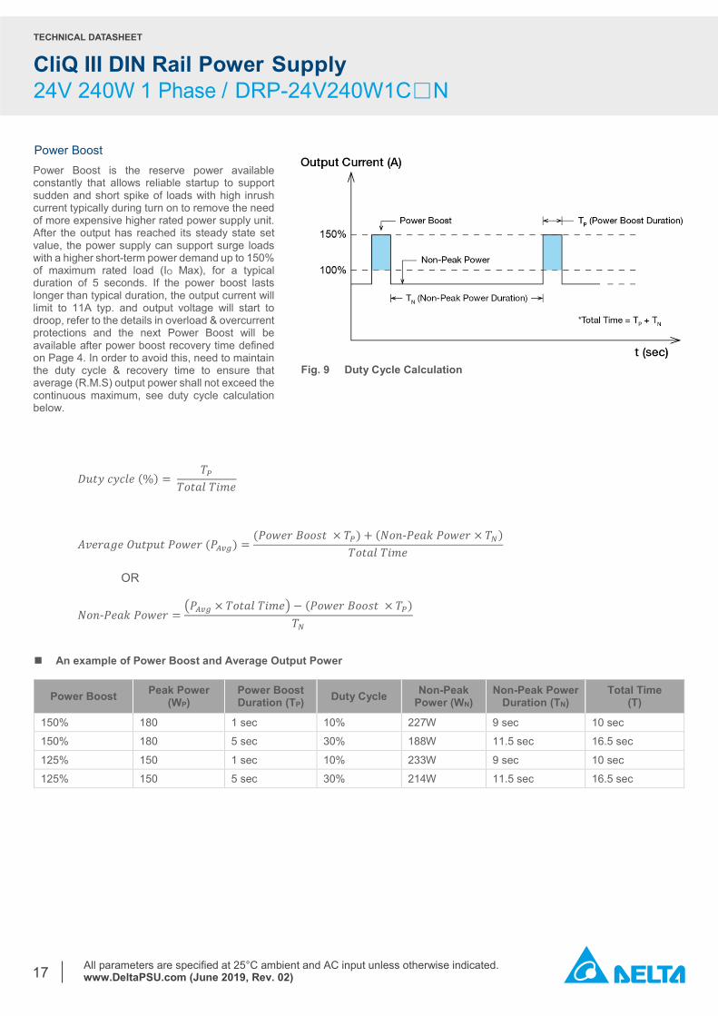
An example of Power Boost and Average Output Power
Power Boost Peak Power (WP)
Power Boost Duration (TP) Duty Cycle Non-Peak
Power (WN) Non-Peak Power
Duration (TN) Total Time
(T)
150% 180 1 sec 10% 227W 9 sec 10 sec
150% 180 5 sec 30% 188W 11.5 sec 16.5 sec
125% 150 1 sec 10% 233W 9 sec 10 sec
125% 150 5 sec 30% 214W 11.5 sec 16.5 sec
Power Boost is the reserve power available constantly that allows reliable startup to support sudden and short spike of loads with high inrush current typically during turn on to remove the need of more expensive higher rated power supply unit. After the output has reached its steady state set value, the power supply can support surge loads with a higher short-term power demand up to 150% of maximum rated load (IO Max), for a typical duration of 5 seconds. If the power boost lasts longer than typical duration, the output current will limit to 11A typ. and output voltage will start to droop, refer to the details in overload & overcurrent protections and the next Power Boost will be available after power boost recovery time defined on Page 4. In order to avoid this, need to maintain the duty cycle & recovery time to ensure that average (R.M.S) output power shall not exceed the continuous maximum, see duty cycle calculation below.
Fig. 9 Duty Cycle Calculation
TECHNICAL DATASHEET
CliQ III DIN Rail Power Supply 24V 240W 1 Phase / DRP-24V240W1C□N
All parameters are specified at 25°C ambient and AC input unless otherwise indicated. www.DeltaPSU.com (June 2019, Rev. 02)
18
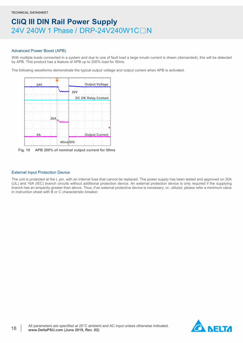
Advanced Power Boost (APB) With multiple loads connected in a system and due to one of fault load a large inrush current is drawn (demanded), this will be detected by APB. This product has a feature of APB up to 200% load for 50ms. The following waveforms demonstrate the typical output voltage and output current when APB is activated.
Fig. 10 APB 200% of nominal output current for 50ms
External Input Protection Device
The unit is protected at the L pin, with an internal fuse that cannot be replaced. The power supply has been tested and approved on 20A (UL) and 16A (IEC) branch circuits without additional protection device. An external protection device is only required if the supplying branch has an ampacity greater than above. Thus, if an external protective device is necessary, or, utilized, please refer a minimum value in instruction sheet with B or C characteristic breaker.
40ms/DIV
0A
20A
Output Current
Output Voltage 24V
20V
DC OK Relay Contact
TECHNICAL DATASHEET
CliQ III DIN Rail Power Supply 24V 240W 1 Phase / DRP-24V240W1C□N
All parameters are specified at 25°C ambient and AC input unless otherwise indicated. www.DeltaPSU.com (June 2019, Rev. 02)
19
Operating Mode Redundant Operation
Parallel Operation
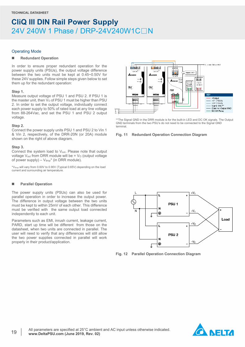
**The Signal GND in the DRR module is for the built-in LED and DC OK signals. The Output GND terminals from the two PSU’s do not need to be connected to the Signal GND terminal. Fig. 11 Redundant Operation Connection Diagram
In order to ensure proper redundant operation for the power supply units (PSUs), the output voltage difference between the two units must be kept at 0.45~0.50V for these 24V supplies. Follow simple steps given below to set them up for the redundant operation: Step 1. Measure output voltage of PSU 1 and PSU 2. If PSU 1 is the master unit, then VO of PSU 1 must be higher than PSU 2. In order to set the output voltage, individually connect each power supply to 50% of rated load at any line voltage from 88-264Vac, and set the PSU 1 and PSU 2 output voltage. Step 2. Connect the power supply units PSU 1 and PSU 2 to Vin 1 & Vin 2, respectively, of the DRR-20N (or 20A) module shown on the right of above diagram. Step 3. Connect the system load to Vout. Please note that output voltage Vout from DRR module will be = VO (output voltage of power supply) – Vdrop* (in DRR module). *Vdrop will vary from 0.60V to 0.90V (Typical 0.65V) depending on the load current and surrounding air temperature.
Fig. 12 Parallel Operation Connection Diagram
The power supply units (PSUs) can also be used for parallel operation in order to increase the output power. The difference in output voltage between the two units must be kept to within 25mV of each other. This difference must be verified with the same output load connected independently to each unit.
Parameters such as EMI, inrush current, leakage current, PARD, start up time will be different from those on the datasheet, when two units are connected in parallel. The user will need to verify that any differences will still allow the two power supplies connected in parallel will work properly in their product/application.
TECHNICAL DATASHEET
CliQ III DIN Rail Power Supply 24V 240W 1 Phase / DRP-24V240W1C□N
All parameters are specified at 25°C ambient and AC input unless otherwise indicated. www.DeltaPSU.com (June 2019, Rev. 02)
20
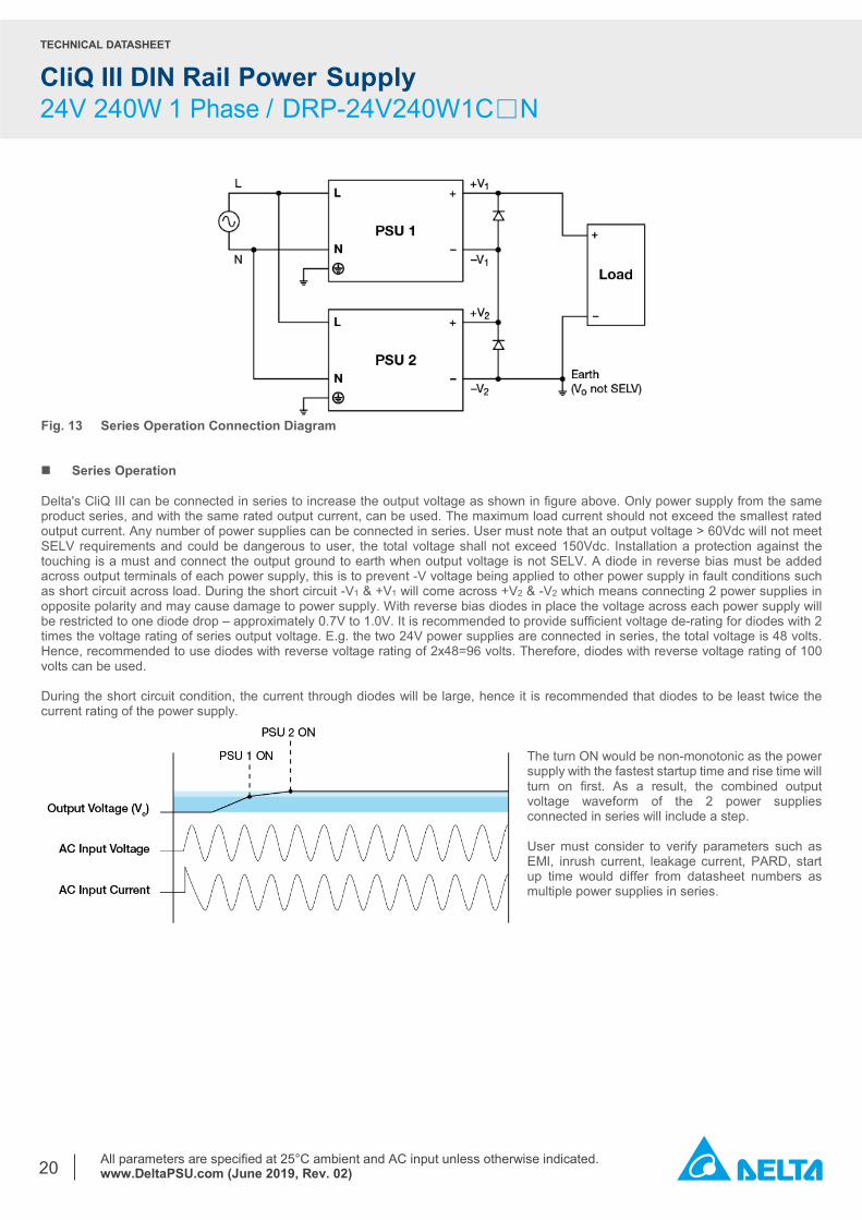
Fig. 13 Series Operation Connection Diagram Series Operation Delta's CliQ III can be connected in series to increase the output voltage as shown in figure above. Only power supply from the same product series, and with the same rated output current, can be used. The maximum load current should not exceed the smallest rated output current. Any number of power supplies can be connected in series. User must note that an output voltage > 60Vdc will not meet SELV requirements and could be dangerous to user, the total voltage shall not exceed 150Vdc. Installation a protection against the touching is a must and connect the output ground to earth when output voltage is not SELV. A diode in reverse bias must be added across output terminals of each power supply, this is to prevent -V voltage being applied to other power supply in fault conditions such as short circuit across load. During the short circuit -V1 & +V1 will come across +V2 & -V2 which means connecting 2 power supplies in opposite polarity and may cause damage to power supply. With reverse bias diodes in place the voltage across each power supply will be restricted to one diode drop – approximately 0.7V to 1.0V. It is recommended to provide sufficient voltage de-rating for diodes with 2 times the voltage rating of series output voltage. E.g. the two 24V power supplies are connected in series, the total voltage is 48 volts. Hence, recommended to use diodes with reverse voltage rating of 2x48=96 volts. Therefore, diodes with reverse voltage rating of 100 volts can be used. During the short circuit condition, the current through diodes will be large, hence it is recommended that diodes to be least twice the current rating of the power supply.
The turn ON would be non-monotonic as the power supply with the fastest startup time and rise time will turn on first. As a result, the combined output voltage waveform of the 2 power supplies connected in series will include a step. User must consider to verify parameters such as EMI, inrush current, leakage current, PARD, start up time would differ from datasheet numbers as multiple power supplies in series.
TECHNICAL DATASHEET
CliQ III DIN Rail Power Supply 24V 240W 1 Phase / DRP-24V240W1C□N
All parameters are specified at 25°C ambient and AC input unless otherwise indicated. www.DeltaPSU.com (June 2019, Rev. 02)
21
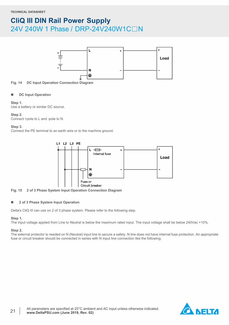
Fig. 14 DC Input Operation Connection Diagram DC Input Operation Step 1. Use a battery or similar DC source. Step 2. Connect +pole to L and -pole to N. Step 3. Connect the PE terminal to an earth wire or to the machine ground.
Fig. 15 2 of 3 Phase System Input Operation Connection Diagram 2 of 3 Phase System Input Operation Delta's CliQ III can use on 2 of 3 phase system. Please refer to the following step. Step 1. The input voltage applied from Line to Neutral is below the maximum rated input. The input voltage shall be below 240Vac +10%. Step 2. The external protector is needed on N (Neutral) input line to secure a safety. N line does not have internal fuse protection. An appropriate fuse or circuit breaker should be connected in series with N input line connection like the following.
TECHNICAL DATASHEET
CliQ III DIN Rail Power Supply 24V 240W 1 Phase / DRP-24V240W1C□N
All parameters are specified at 25°C ambient and AC input unless otherwise indicated. www.DeltaPSU.com (June 2019, Rev. 02)
22
Others Delta RoHS Compliant
Restriction of the usage of hazardous substances
The European directive 2011/65/EU limits the maximum impurity level of homogeneous materials such as lead, mercury, cadmium, chrome, polybrominated flame retardants PBB and PBDE for the use in electrical and electronic equipment. RoHS is the abbreviation for “Restriction of the use of certain hazardous substances in electrical and electronic equipment”.
This product conforms to this standard. Conformal Coating
The Protective Coating Technology
Delta Electronics Group has designed the perfect dipping technique which penetrates everywhere including under device, and prevents leakage. The conformal coating dipping can be applied to PCBAs or circuit board. The coating preserves the performance of precision electronic primarily by preventing ionizable contaminants such as salt from reaching circuit nodes, where the material slumps around sharp edges. This can be a problem especially in highly conversing atmosphere.
PFC – Norm EN 61000-3-2
Line Current Harmonic content
Typically, the input current waveform is not sinusoidal due to the periodic peak charging of the input capacitor. In industrial environments, compliance with EN 61000-3-2 is only necessary under special conditions. Complying to this standard can have some technical drawbacks, such as lower efficiency; and, can also result in higher product cost. Frequently, the user does not profit from compliance to this standard; therefore, it is important to know whether it is mandatory to meet this standard for a specific application.
Attention Delta provides all information in the datasheets on an “AS IS” basis and does not offer any kind of warranty through the information for using the product. In the event of any discrepancy between the information in the catalog and datasheets, the datasheets shall prevail (please refer to www.DeltaPSU.com for the latest datasheets information). Delta shall have no liability of indemnification for any claim or action arising from any error for the provided information in the datasheets. Customer shall take its responsibility for evaluation of using the product before placing an order with Delta.
Delta reserves the right to make changes to the information described in the datasheets without notice.