Embed Size (px)
Citation preview

Lectures 1&2 F. Morrison CM3110 8/30/2015
2015 1
© Faith A. Morrison, Michigan Tech U.
CM3110
Transport Processes and Unit Operations I
Professor Faith Morrison
Department of Chemical EngineeringMichigan Technological University
www.chem.mtu.edu/~fmorriso/cm310/cm310.html
CM3110 - Momentum and Heat TransportCM3120 – Heat and Mass Transport
1
© Faith A. Morrison, Michigan Tech U.
Why study fluid mechanics?
2

Lectures 1&2 F. Morrison CM3110 8/30/2015
2015 2
© Faith A. Morrison, Michigan Tech U.
Why study fluid mechanics?
•It’s required for my degree
3
© Faith A. Morrison, Michigan Tech U.
Why study fluid mechanics?
•It’s required for my degree (too literal)
4

Lectures 1&2 F. Morrison CM3110 8/30/2015
2015 3
© Faith A. Morrison, Michigan Tech U.
Why study fluid mechanics?
•It’s required for my degree (too literal)
•Fluids are involved in engineered systems
5
Image from: money.cnn.com
Image from: newegg.com
© Faith A. Morrison, Michigan Tech U.
Why study fluid mechanics?
•It’s required for my degree (too literal)
•Fluids are involved in engineering systems (many devices that employ fluids can be operated and maintained and sometimes designed without detailed mathematical analysis)
6

Lectures 1&2 F. Morrison CM3110 8/30/2015
2015 4
© Faith A. Morrison, Michigan Tech U.
Why study fluid mechanics?
•Modern engineering systems are complex and often cannot be operated and maintained without analytical understanding
7
•Design of new systems will come from high-tech innovation, which can only come from detailed, analytical understanding of how physics/nature works
Image: wikipedia.org
Imag
e: p
lane
tforw
ard.
ca
© Faith A. Morrison, Michigan Tech U.
O2 heat
exchanger
pump
membrane oxygenator – oxygen goes into blood; carbon dioxide comes out
O2
MO
spent blood
fresh blood
Membrane Oxygenator(Heart-Lung Machine)
Secondary flow drives the O2 mass transfer
8

Lectures 1&2 F. Morrison CM3110 8/30/2015
2015 5
© F
aith
A.
Mor
rison
, M
ichi
gan
Tech
U.
Artificial Heart
Image: health.howstuffworks.com/medicine/modern/artificial-heart.htm
9
Microfluidics – Lab on a Chip
© F
aith
A.
Mor
rison
, M
ichi
gan
Tech
U.
www.nature.com/nmeth/journal/v4/n8/full/nmeth0807-665.html
10
Sensors, diagnostics

Lectures 1&2 F. Morrison CM3110 8/30/2015
2015 6
And more. . . .
© F
aith
A.
Mor
rison
, M
ichi
gan
Tech
U.
11
HelicoptersAirplanesQuieter fansFlexible body armorUndersea oil drillingSurgeryFood processingPlastics2D and 3D printingBattery manufactureCelestial explorationVolcanos Biomedical devices (stents, artificial organs, prosthetics)Sensor development…
Ima
ge fr
om
: e
n.w
ikip
edi
a.o
rg
© Faith A. Morrison, Michigan Tech U.
Where to start?
12
We’ve already started.

Lectures 1&2 F. Morrison CM3110 8/30/2015
2015 7
© Faith A. Morrison, Michigan Tech U.
Where to start?
13
There are problems that can be addressed with a macroscopic energy balance:
2
,
2 2
, ,212 1 2 12 1 21
ΔΔΔ
2
p p(z z )
2
s on
s on
Wvpg z F
vg
m
m
v WF
1. single-input, single output2. Steady state3. Constant density (incompressible fluid)4. Temperature approximately constant5. No phase change, no chemical rxn6. Insignificant amounts of heat transferred
The Mechanical Energy Balance
Assumptions:
friction
© Faith A. Morrison, Michigan Tech U.
Flow in Pipes and Fittings
14
For example:
pump
ID=3.0 in ID=2.0 in
75 ft
tank
50 ft 40 ft
20 ft
8 ft
1
2
1. Single-input, single output2. Steady state3. Constant density (incompressible fluid)4. Temperature approximately constant5. No phase change, no chemical rxn6. Insignificant amounts of heat transferred
Mechanical Energy Balance

Lectures 1&2 F. Morrison CM3110 8/30/2015
2015 8
© Faith A. Morrison, Michigan Tech U.
)( ftH
)(1,2 VH
)(, VH sd
)/( mingalV
valve 50% open
valve full open
pump
system
Centrifugal Pumps
What flow rate does a centrifugal pump produce?
Answer: Depends on how much work it is asked to do.
15
For example:
Calculate with the Mechanical Energy
Balance(CM2120, CM3215)
© Faith A. Morrison, Michigan Tech U.
16
We can apply the MEB to many important engineering systems
1. single-input, single output2. Steady state3. Constant density (incompressible fluid)4. Temperature approximately constant5. No phase change, no chemical rxn6. Insignificant amounts of heat
transferred
MEB Assumptions:
Ima
ge fr
om
: w
ww
.ep
a.g
ov
Image from: www.directindustry.com
Image from: www.processindustryforum.com
Image from: www.directindustry,com
Calculate: Work,
pressures, flows

Lectures 1&2 F. Morrison CM3110 8/30/2015
2015 9
© Faith A. Morrison, Michigan Tech U.
17
2
,
2 2
, ,212 1 2 12 1 21
ΔΔΔ
2
p p(z z )
2
s on
s on
Wvpg z F
vg
m
m
v WF
The Mechanical Energy Balance
Where do we get this?
This is the friction due to wall drag (straight pipes) and fittings and valves.
(Rev
iew
)
friction
© Faith A. Morrison, Michigan Tech U.
18
The Mechanical Energy Balance – Friction Term
The friction has been measured and published in this form:
Straight pipes:
2
42straight pipes
vLF f
D
Use literature plot of fas a function of Reynolds Number
Fittings and Valves:
2
, 2fittings fvalves
vF K
Use literature tables of Kf for laminar and turbulent flow
(Rev
iew
)

Lectures 1&2 F. Morrison CM3110 8/30/2015
2015 10
2
42ifriction f i
i
vLF f K n
D
length of straight pipe
number of each type of fitting
friction-loss coefficients
(from literature; see McCabe et al., Geankoplis, or
Morrison Chapter 1)
Friction term in Mechanical Energy Balance
© Faith A. Morrison, Michigan Tech U.
If the velocity changes within the system (e.g. pipe diameter changes), then we need different
friction terms for each velocity
Note that friction overall is directly a function of velocity)
(see McCabe et al., or Morrison Chapter 1, or Perry’s
Chem Eng Handbook)(R
evie
w)
Note f is a function of velocity)
(from literature; the Moody chart)
friction
Reynolds Number
© Faith A. Morrison, Michigan Tech U.
Fanning Friction Factor
DvzRe
lengthpipeL
droppressurePP
viscosity
diameterpipeD
velocityaveragev
density
L
z
0
Flow rate
Pressure Drop
Data are organized in terms of two dimensionless parameters:
2
0
21
41
z
L
vDL
PPf
(Rev
iew
)

Lectures 1&2 F. Morrison CM3110 8/30/2015
2015 11
(image from: Geankoplis)
Moody Chart: Data Correlation for Friction in Straight Pipes
© Faith A. Morrison, Michigan Tech U.
Moody Chart
Re
16
(Rev
iew
)
© Faith A. Morrison, Michigan Tech U.
22
Friction Loss from Fittings
(source: Morrison, Chapter 1; originally from Perry’s Handbook)

Lectures 1&2 F. Morrison CM3110 8/30/2015
2015 12
© Faith A. Morrison, Michigan Tech U.
Example 1
23
What is the pressure change over 50 meters of 1/2 inch inner-diameter straight pipe? The average velocity is 5.2 ft/s and the pipe is smooth.
© Faith A. Morrison, Michigan Tech U.
Example 1
24
What is the pressure change over 50 meters of 1/2 inch inner-diameter straight pipe? The average velocity is 5.2 ft/s and the pipe is smooth.
ANSWER: 18 psi

Lectures 1&2 F. Morrison CM3110 8/30/2015
2015 13
© Faith A. Morrison, Michigan Tech U.
Example 2
25
What is the flow rate at the drain from a constant-head tank with a fluid level h? You may neglect frictional losses.
© Faith A. Morrison, Michigan Tech U.
Example 2
26
What is the flow rate at the drain from a constant-head tank with a fluid level h? You may neglect frictional losses.
ANSWER: 2

Lectures 1&2 F. Morrison CM3110 8/30/2015
2015 14
For more examples: see HW1; Prerequisite readings
27
Exam 1: Next Tues 6:30-8:00pmLast year’s exam and solution is on the web. TA help session is Monday nightTopics: vectors, linear algebra, integration, MEB, fluid statics
(Rev
iew
)
© F
aith
A.
Mor
rison
, M
ichi
gan
Tech
U.
• It is limited in application:
• It cannot determine flow patterns
• It does not model momentum exchanges
• It cannot be adapted to systems other than those for which it was designed (see list above)
© Faith A. Morrison, Michigan Tech U.
The Mechanical Energy Balance (MEB) is a macroscopic analysis.
28
1. single-input, single output2. Steady state3. Constant density (incompressible fluid)4. Temperature approximately constant5. No phase change, no chemical rxn6. Insignificant amounts of heat transferred
2 2
, ,212 1 2 12 1 21
p p(z z )
2s onv v W
g Fm
friction

Lectures 1&2 F. Morrison CM3110 8/30/2015
2015 15
© Faith A. Morrison, Michigan Tech U.
Energy balances (the MEB) can only take us so far with fluids modeling (due to assumptions).
29
To understand complex flows, we must use
the MOMENTUM balance.
Ima
ge fr
om
: w
ha
tsu
pw
ithth
at.c
om
Ima
ge fr
om
: w
ww
.12
3rf
.co
m
Image from: commons.wikipedia.orgNaruto Whirlpools, Japan
Image from: www-math.mtu.edu
© Faith A. Morrison, Michigan Tech U.
Momentum Balance: Newton’s 2nd Law of Motion
30
Ima
ge fr
om
: w
ww
.te
xtu
rex.
com
PH 2100: apply to individual bodies
CM 3110: apply to a continuum
See also: http://youtu.be/6KKNnjFpGto

Lectures 1&2 F. Morrison CM3110 8/30/2015
2015 16
© Faith A. Morrison, Michigan Tech U.
Fluid Mechanics
31
• Continuum (density, velocity, stress fields)
• Control volume
• Stress in a fluid at a point (stress tensor)
• Stress and deformation (Newtonian constitutive equation)
• Microscopic and macroscopic momentum balances
• Internal flows – pipes, conduits
• External flows – drag, boundary layers
• Advanced fluid mechanics – complex shapes
, ,
control volume
© Faith A. Morrison, Michigan Tech U.
Momentum . . .
32
is a vector
Microscopic momentum balance
gvPvvt
v
2
Macroscopic momentum balance
2# #
1 1
cosˆ ˆ
ii
streams streams
CVi i A
A
A vdv pAn R M g
dt
P
So we need vector math.
Ch 6
Ch 9
3

Lectures 1&2 F. Morrison CM3110 8/30/2015
2015 17
zrz
r
xyzz
y
x
v
v
v
v
v
v
v
v
v
v
1233
2
1
Same vector, different coordinate systems, different components.
magnitudevectorvv
vectorunitv
v
v ˆ
© Faith A. Morrison, Michigan Tech U.
We choose coordinate systems for convenience.
Vectors
33
1x rv v v Note:
(usually)
© Faith A. Morrison, Michigan Tech U.
creeping flow (sphere)
0.
01
0.2
0.6
1.2
2.0
3.0
Vector plot of the velocity field in creeping flow
around a sphere
The flow is a steady upward flow; the length and direction of the vector indicates the velocity at that location.
34
Fluid velocity is a vector field
, ,

Lectures 1&2 F. Morrison CM3110 8/30/2015
2015 18
Vectors – Cartesian coordinate system
© Faith A. Morrison, Michigan Tech U.
•We do algebra with the basis vectors the same way as with other quantities
•The Cartesian basis vectors are constant (do not change with position)
35
(three ways of writing the same thing, the Cartesian
basis vectors)
© Faith A. Morrison, Michigan Tech U.
Vectors – Cylindrical coordinate system
•The cylindrical basis vectors are variable (depend on position)
ˆ ˆ ˆcos sin
ˆ ˆ ˆsin cos
ˆ ˆ
r x y
x y
z z
e e e
e e e
e e
cos
sin
x r
y r
z z
P
x
y
z
r
z
36
(see inside back cover;
also, supplemental handouts)

Lectures 1&2 F. Morrison CM3110 8/30/2015
2015 19
© Faith A. Morrison, Michigan Tech U.
Vectors – Spherical coordinate system
•The spherical basis vectors are variable (with position)
ˆ ˆ ˆ ˆsin cos sin sin cos
ˆ ˆ ˆ ˆcos cos cos sin ( sin )
ˆ ˆ ˆsin cos
r x y z
x y z
x y
e e e e
e e e e
e e e
sin cos
sin sin
cos
x r
y r
z r
37
(see inside back cover;
also, supplemental handouts)
Note: spherical coordinate system in use by the fluid mechanics community uses 0
as the angle from the =axis to the point.
© Faith A. Morrison, Michigan Tech U.
creeping flow (sphere)
0.
01
0.2
0.6
1.2
2.0
3.0
38
Fluid Velocity is a Vector Field
Velocity magnitude and direction vary with position
, ,
Lectures 1&2 F. Morrison CM3110 8/30/2015
2015 20
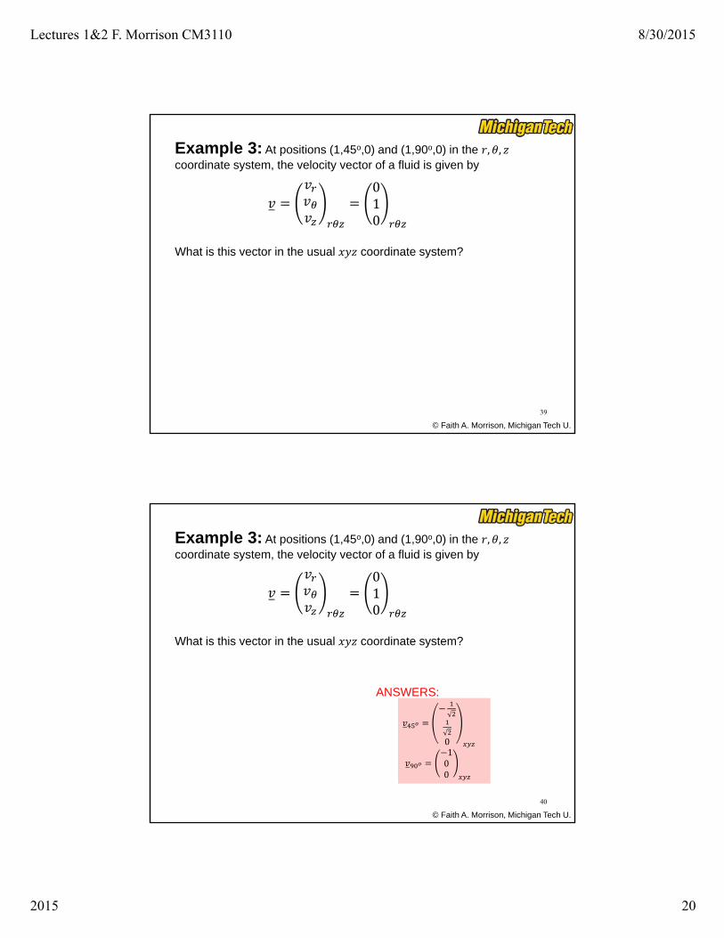
Example 3: At positions (1,45o,0) and (1,90o,0) in the , ,coordinate system, the velocity vector of a fluid is given by
© Faith A. Morrison, Michigan Tech U.
39
What is this vector in the usual coordinate system?
010
© Faith A. Morrison, Michigan Tech U.
40
0100
ANSWERS:
Example 3: At positions (1,45o,0) and (1,90o,0) in the , ,coordinate system, the velocity vector of a fluid is given by
What is this vector in the usual coordinate system?
010

Lectures 1&2 F. Morrison CM3110 8/30/2015
2015 21
© Faith A. Morrison, Michigan Tech U.
We use Calculus in Fluid Mechanics to:
1. Calculate flow rate,
2. Calculate average velocity, ⟨ ⟩
3. Express forces on surfaces due to fluids (vectors)
4. Express torques on surfaces due to fluids (vectors)
41
© Faith A. Morrison, Michigan Tech U.
2
0 0
ˆ( ) ( )
( )
area
R
z
Q v n d area
Q v r rdrd
1. Calculate Flow rate: or VQ
is the component of v in the direction normal to the area
ˆv n
General:
Tube flow:
42

Lectures 1&2 F. Morrison CM3110 8/30/2015
2015 22
© Faith A. Morrison, Michigan Tech U.
Common surface shapes:
2
: ( )
: ( )
: ( )
: ( ) ( ) sin sin
rectangular d area dxdy
circular d area r drd
surface of cylinder d area Rd dz
spherical d area rd r d r d d
43
(see inside back cover;
also, supplemental handouts)
© Faith A. Morrison, Michigan Tech U.
Example 4: Calculate the flow rate in flow down an incline plane of width W.
44
22
2
)cos()( xH
gxvz
HMomentum balance calculation gives:
(we will learn how to get this equation for ; here it is given)

Lectures 1&2 F. Morrison CM3110 8/30/2015
2015 23
© Faith A. Morrison, Michigan Tech U.
Example 4: Calculate the flow rate in flow down an incline plane of width W.
45
22
2
)cos()( xH
gxvz
HMomentum balance calculation gives:
ANSWER:
3
(we will learn how to get this equation for ; here it is given)
© Faith A. Morrison, Michigan Tech U.
2. Calculate Average velocity:
2
Qv
area
Qv
R
v
“area” is the cross-sectional area normal to flow
General:
Tube flow:
46
Lectures 1&2 F. Morrison CM3110 8/30/2015
2015 24
© Faith A. Morrison, Michigan Tech U.
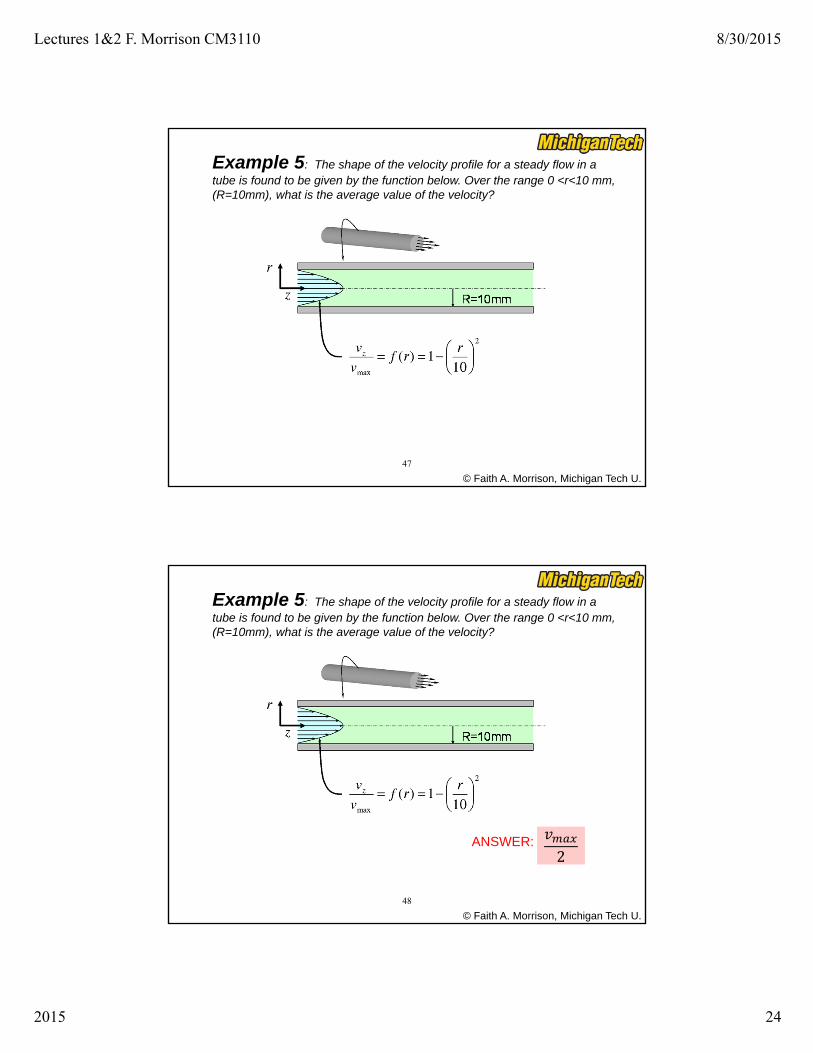
Example 5: The shape of the velocity profile for a steady flow in a tube is found to be given by the function below. Over the range 0 <r<10 mm, (R=10mm), what is the average value of the velocity?
47
© Faith A. Morrison, Michigan Tech U.
48
ANSWER:2
Example 5: The shape of the velocity profile for a steady flow in a tube is found to be given by the function below. Over the range 0 <r<10 mm, (R=10mm), what is the average value of the velocity?

Lectures 1&2 F. Morrison CM3110 8/30/2015
2015 25
© Faith A. Morrison, Michigan Tech U.
3. Express forces on surfaces due to fluids
49
⋅ ΠTotal fluid force on a
surface
Π ≡ Total stress tensor
© Faith A. Morrison, Michigan Tech U.
Example 6: In a liquid of density , what is the net fluid force on a submerged sphere (a ball or a balloon)? What is the direction of the force and how does the magnitude of the fluid force vary with fluid density?
50
(p81)
H0f
air
x
z

Lectures 1&2 F. Morrison CM3110 8/30/2015
2015 26
© Faith A. Morrison, Michigan Tech U.
Solution: We will be able to do this in this course (Ch4, p257).
From expression for force due to fluid, obtain: (in spherical coordinates)
We can do the math from here. (Calc 3)
51
⋅ ΠTotal fluid force on a
surface
sin
© Faith A. Morrison, Michigan Tech U.
Solution: We will be able to do this in this course (Ch4, p257).
From expression for force due to fluid, obtain: (in spherical coordinates)
52
ANSWER: (see p83)
00
43
⋅ ΠTotal fluid force on a
surface
sin

Lectures 1&2 F. Morrison CM3110 8/30/2015
2015 27
© Faith A. Morrison, Michigan Tech U.
4. Express torques on surfaces due to fluids
ˆS at surface
total fluid torqueR n dS
on a surfaceT
R lever arm
We will learn to write the stress tensor for our systems; then we can calculate stresses, torques.
53
pI total stress tensor
(Points from axis of rotation to position where torque is applied)
Example 7, Torque in Couette Flow: A cup-and-bob apparatus is widely used to measure viscosities for fluids. For the apparatus below, what is the torque needed to turn the inner cylinder (called the bob) at an angular speed of ?
© Faith A. Morrison, Michigan Tech U.
54

Lectures 1&2 F. Morrison CM3110 8/30/2015
2015 28
© Faith A. Morrison, Michigan Tech U.
Torque in Couette FlowSolution:
1. Solve for velocity field (microscopic momentum bal)
2. Calculate stress tensor3. Formulate equation for torque (an integral)4. Integrate5. Apply boundary conditions
55
© Faith A. Morrison, Michigan Tech U.
Torque in Couette FlowSolution:
56
See problem 6.22 p487
2
2
0
1
0r z
R r Rv
R r
Velocity solution:
Tv v
pI
ˆS at surface
total fluid torqueR n dS
on a surfaceT
What is lever arm, R?
etc…

Lectures 1&2 F. Morrison CM3110 8/30/2015
2015 29
© Faith A. Morrison, Michigan Tech U.
Torque in Couette FlowSolution:
57
See problem 6.22 p487
ˆS at surface
total fluid torqueR n dS
on a surfaceT
ANSWER: (see p308)
4 Ω1
001
© Faith A. Morrison, Michigan Tech U.
Summary of Quick Start
A: Mechanical Energy Balance
B): Use Calculus in Fluid Mechanics to
1. Calculate flow rate 2. Calculate average velocity3. Express forces on surfaces due to fluids4. Express torques on surfaces due to fluids
58
1. SI-SO, steady, incompressible, no rxn, no Δ , no 2. Macroscopic3. Choose points 1 and 2 wisely4. Solve for or , or , velocity, elevation
friction2
,
2 2
, ,212 1 2 12 1 21
ΔΔΔ
2
p p(z z )
2
s on
s on
Wvpg z F
vg
m
m
v WF

Lectures 1&2 F. Morrison CM3110 8/30/2015
2015 30
© Faith A. Morrison, Michigan Tech U.
59