Embed Size (px)
Citation preview

CMPT 250: Computer Architecture
Using LogicWorks™ 5
Tutorial Part 1
Somsubhra Sharangi
What is VHDL?
� A high level language to describe digital circuit
� Different that a programming language ( such as Java) :
� It cannot be “run”. Can only be “simulated”.
� Sometimes Inputs are given in parallel(e.g. two inputs of an AND gates)
� Used to model only digital circuit system. Specific, not as versatile
� Other HDL: Verilog, System C
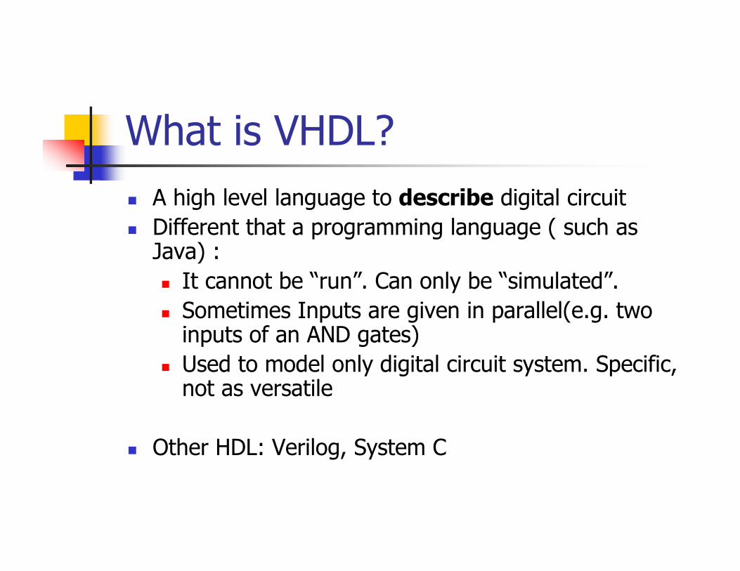
Why Learn VHDL?
� Easy to design Large Scale and complex circuits through modular approach of programming.
� Easy verification of your design without having to use expensive hardware.
� Faster and more robust design with the code�test�improve cycle.
Requirement Analysis
HDL/ RTL Design
Functional Verification
Computer Architecture
GDSII
IC Fabrication
EDA
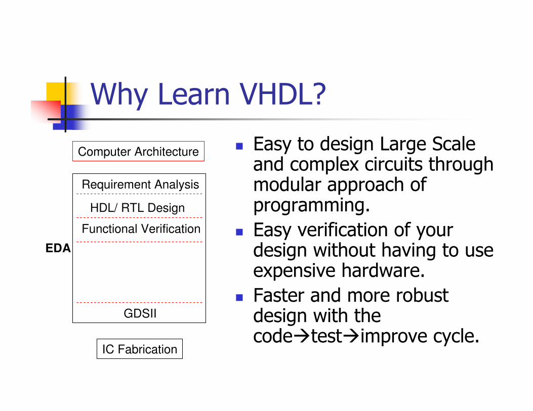
A First Example: 2 input AND
� Open LogicWorks
� File�New
� Model Wizard
� Empty Model
� Independent
Design
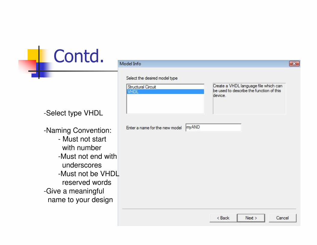
Contd.
-Select type VHDL
-Naming Convention:
- Must not start
with number
-Must not end with
underscores
-Must not be VHDL
reserved words
-Give a meaningful
name to your design
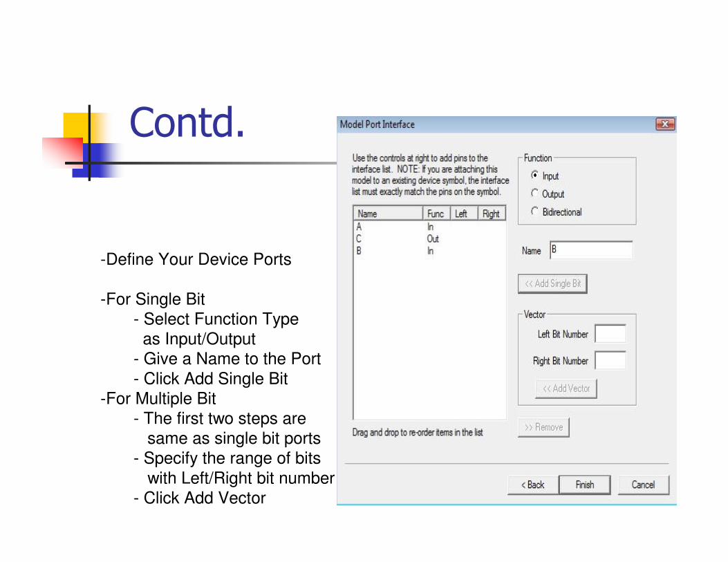
Contd.
-Define Your Device Ports
-For Single Bit
- Select Function Type
as Input/Output
- Give a Name to the Port
- Click Add Single Bit
-For Multiple Bit
- The first two steps are
same as single bit ports
- Specify the range of bits
with Left/Right bit number
- Click Add Vector
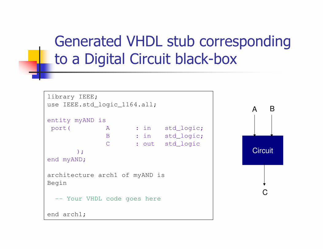
Generated VHDL stub corresponding to a Digital Circuit black-box
library IEEE;
use IEEE.std_logic_1164.all;
entity myAND is
port( A : in std_logic;
B : in std_logic;
C : out std_logic
);
end myAND;
architecture arch1 of myAND is
Begin
-- Your VHDL code goes here
end arch1;
Circuit
A B
C
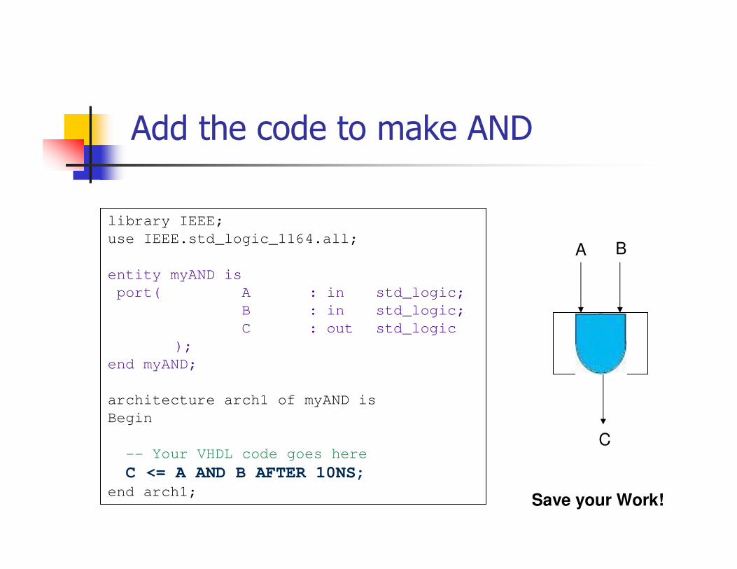
Add the code to make AND
library IEEE;
use IEEE.std_logic_1164.all;
entity myAND is
port( A : in std_logic;
B : in std_logic;
C : out std_logic
);
end myAND;
architecture arch1 of myAND is
Begin
-- Your VHDL code goes here
C <= A AND B AFTER 10NS;
end arch1;
A B
C
Save your Work!
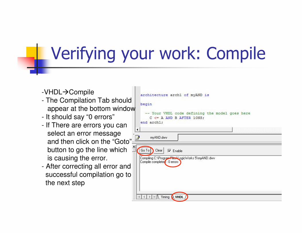
Verifying your work: Compile
-VHDL�Compile
- The Compilation Tab should
appear at the bottom window
- It should say “0 errors”
- If There are errors you can
select an error message
and then click on the “Goto”
button to go the line which
is causing the error.
- After correcting all error and
successful compilation go to
the next step
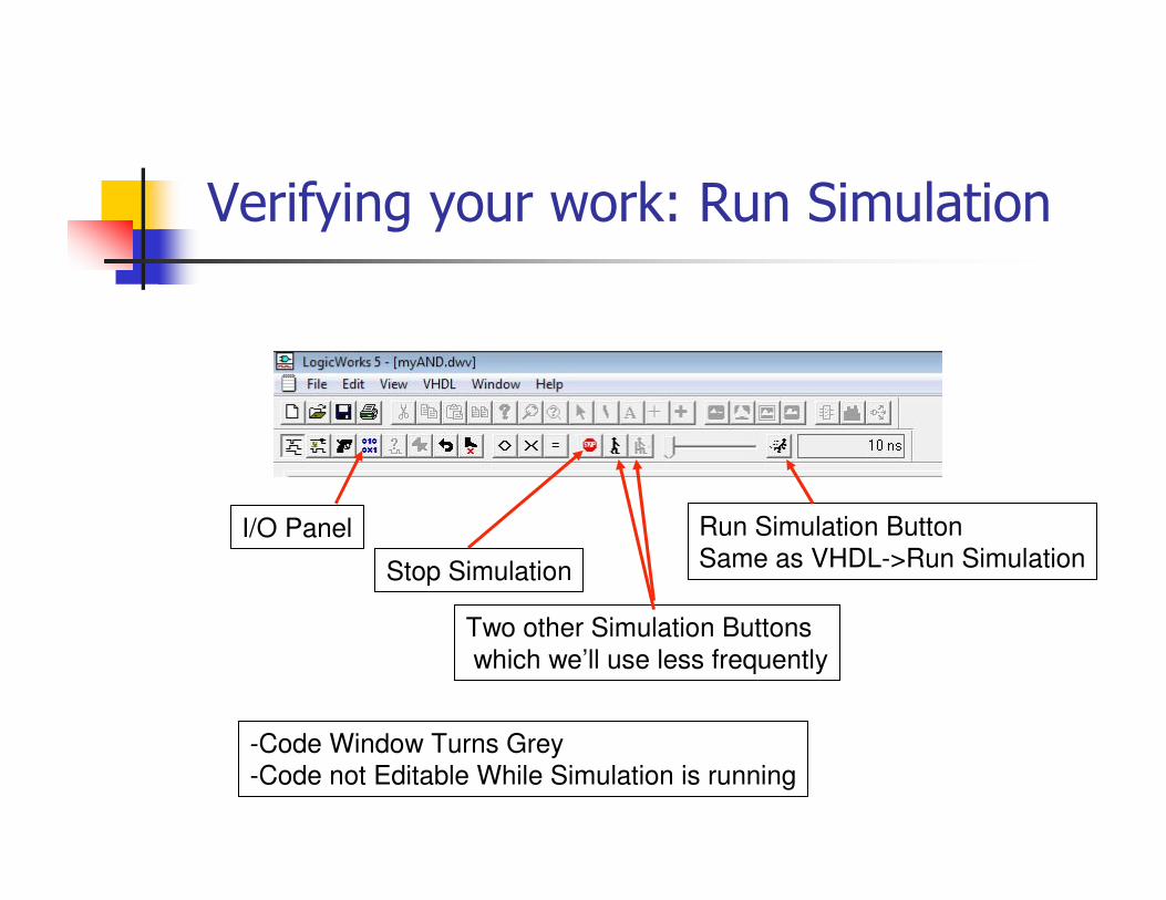
Verifying your work: Run Simulation
Run Simulation Button
Same as VHDL->Run SimulationStop Simulation
Two other Simulation Buttons
which we’ll use less frequently
-Code Window Turns Grey
-Code not Editable While Simulation is running
I/O Panel
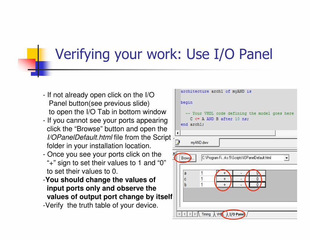
Verifying your work: Use I/O Panel
- If not already open click on the I/O
Panel button(see previous slide)
to open the I/O Tab in bottom window
- If you cannot see your ports appearing
click the “Browse” button and open the
I/OPanelDefault.html file from the Script
folder in your installation location.
- Once you see your ports click on the
“+” sign to set their values to 1 and “0”
to set their values to 0.
-You should change the values of input ports only and observe the
values of output port change by itself
-Verify the truth table of your device.
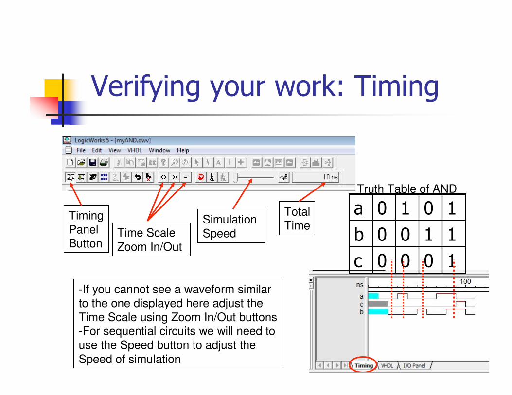
Verifying your work: Timing
Total
TimeTime Scale
Zoom In/Out
-If you cannot see a waveform similar
to the one displayed here adjust the
Time Scale using Zoom In/Out buttons
-For sequential circuits we will need to
use the Speed button to adjust the
Speed of simulation
Timing
Panel
Button
Simulation
Speed
1000c
1100b
1010aTruth Table of AND
Looking Back
� At this point you have successfully wrote and tested the VHDL code for a two input AND gate
� Take some time to look back and familiarize with the procedure of Coding and Testing
� Make sure you remember the different LogicWorks tools and controls you just learnt.
� We’ll try some more circuits, but the basic procedure will remain same. Only thing that will change is we’ll write different VHDL Code and will try out more test cases.
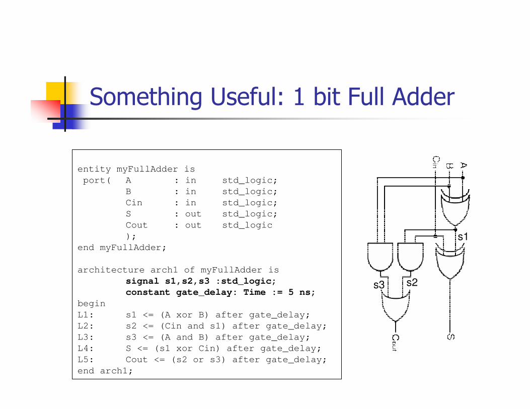
Something Useful: 1 bit Full Adder
entity myFullAdder is
port( A : in std_logic;
B : in std_logic;
Cin : in std_logic;
S : out std_logic;
Cout : out std_logic
);
end myFullAdder;
architecture arch1 of myFullAdder is
signal s1,s2,s3 :std_logic;
constant gate_delay: Time := 5 ns;
begin
L1: s1 <= (A xor B) after gate_delay;
L2: s2 <= (Cin and s1) after gate_delay;
L3: s3 <= (A and B) after gate_delay;
L4: S <= (s1 xor Cin) after gate_delay;
L5: Cout <= (s2 or s3) after gate_delay;
end arch1;
s1
s2s3
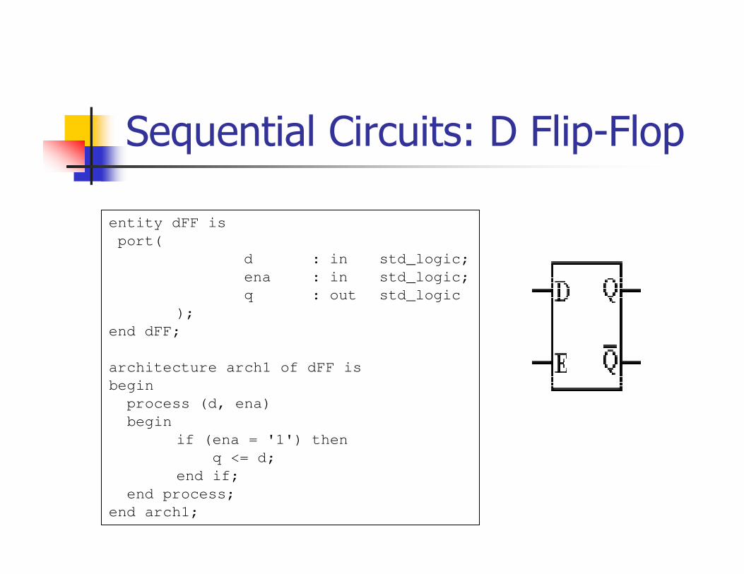
Sequential Circuits: D Flip-Flop
entity dFF is
port(
d : in std_logic;
ena : in std_logic;
q : out std_logic
);
end dFF;
architecture arch1 of dFF is
begin
process (d, ena)
begin
if (ena = '1') then
q <= d;
end if;
end process;
end arch1;
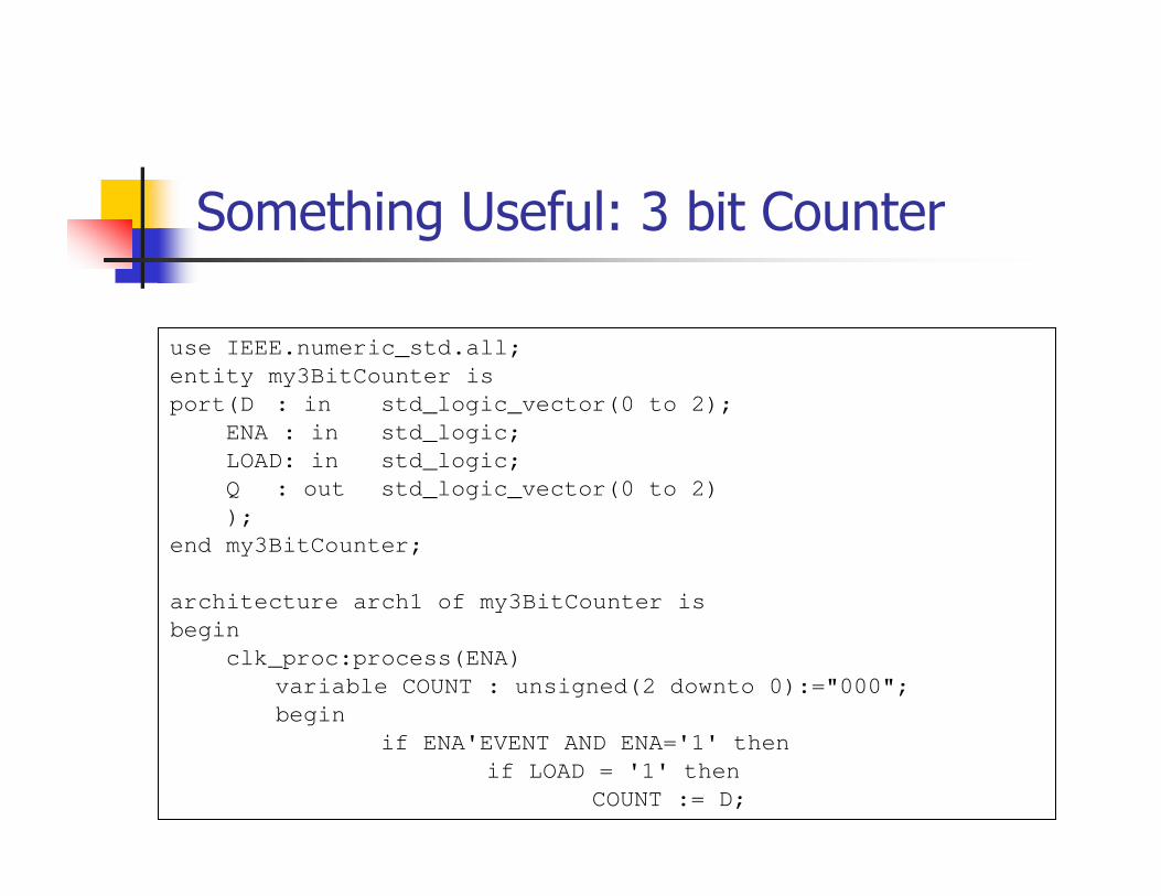
Something Useful: 3 bit Counter
use IEEE.numeric_std.all;
entity my3BitCounter is
port(D : in std_logic_vector(0 to 2);
ENA : in std_logic;
LOAD: in std_logic;
Q : out std_logic_vector(0 to 2)
);
end my3BitCounter;
architecture arch1 of my3BitCounter is
begin
clk_proc:process(ENA)
variable COUNT : unsigned(2 downto 0):="000";
begin
if ENA'EVENT AND ENA='1' then
if LOAD = '1' then
COUNT := D;
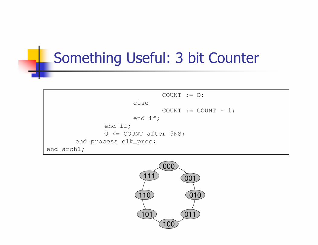
Something Useful: 3 bit Counter
COUNT := D;
else
COUNT := COUNT + 1;
end if;
end if;
Q <= COUNT after 5NS;
end process clk_proc;
end arch1;
000
101 011
111 001
110 010
100
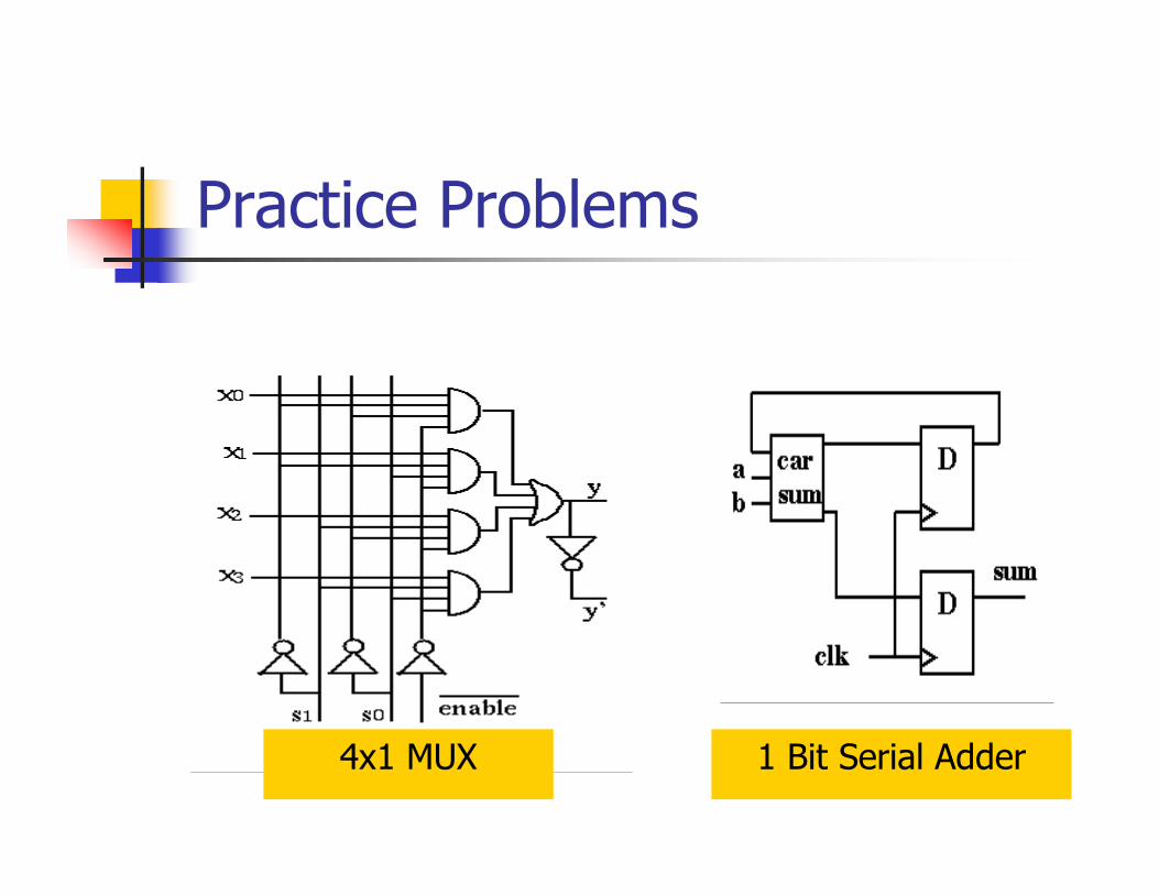
Practice Problems
4x1 MUX 1 Bit Serial Adder