Embed Size (px)
Citation preview
CMPT 454
Memory hierarchy Hard disks
Architecture
Processing requests
Writing to disk
Hard disk reliability and efficiency
RAID
Solid State Drives Buffer management Data storage
John Edgar 2
1.1
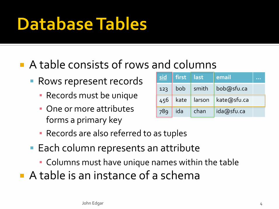
A table consists of rows and columns
Rows represent records
▪ Records must be unique
▪ One or more attributesforms a primary key
▪ Records are also referred to as tuples
Each column represents an attribute
▪ Columns must have unique names within the table
A table is an instance of a schema
John Edgar 4
sid first last email …
123 bob smith [email protected]
456 kate larson [email protected]
789 ida chan [email protected]
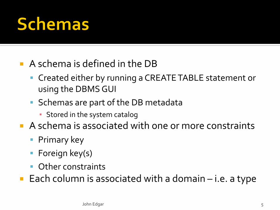
A schema is defined in the DB
Created either by running a CREATE TABLE statement or using the DBMS GUI
Schemas are part of the DB metadata▪ Stored in the system catalog
A schema is associated with one or more constraints
Primary key
Foreign key(s)
Other constraints
Each column is associated with a domain – i.e. a type
John Edgar 5
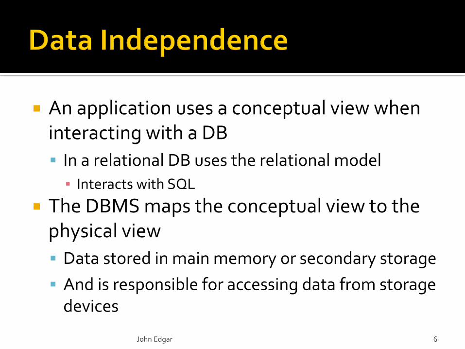
An application uses a conceptual view when interacting with a DB
In a relational DB uses the relational model
▪ Interacts with SQL
The DBMS maps the conceptual view to the physical view
Data stored in main memory or secondary storage
And is responsible for accessing data from storage devices
John Edgar 6
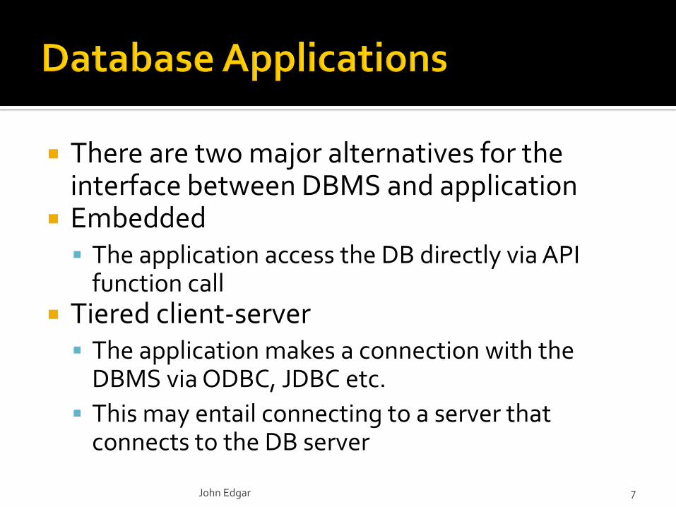
There are two major alternatives for the interface between DBMS and application
Embedded The application access the DB directly via API
function call Tiered client-server
The application makes a connection with the DBMS via ODBC, JDBC etc.
This may entail connecting to a server that connects to the DB server
John Edgar 7
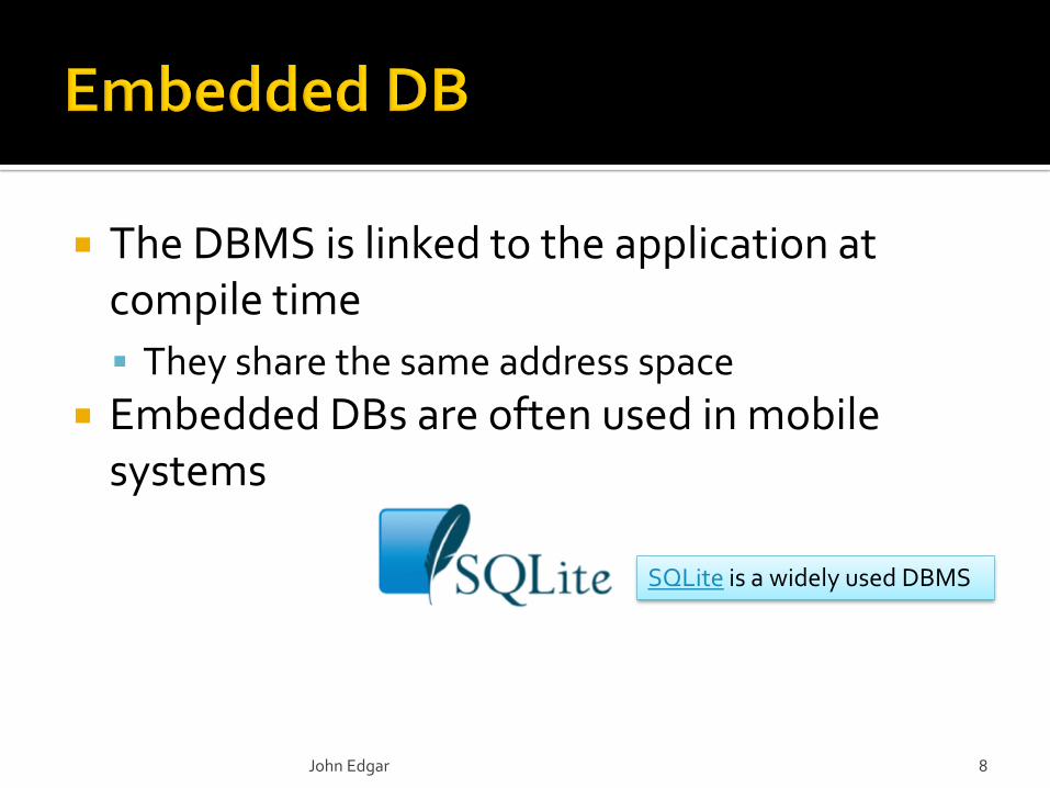
The DBMS is linked to the application at compile time
They share the same address space
Embedded DBs are often used in mobile systems
John Edgar 8
SQLite is a widely used DBMS
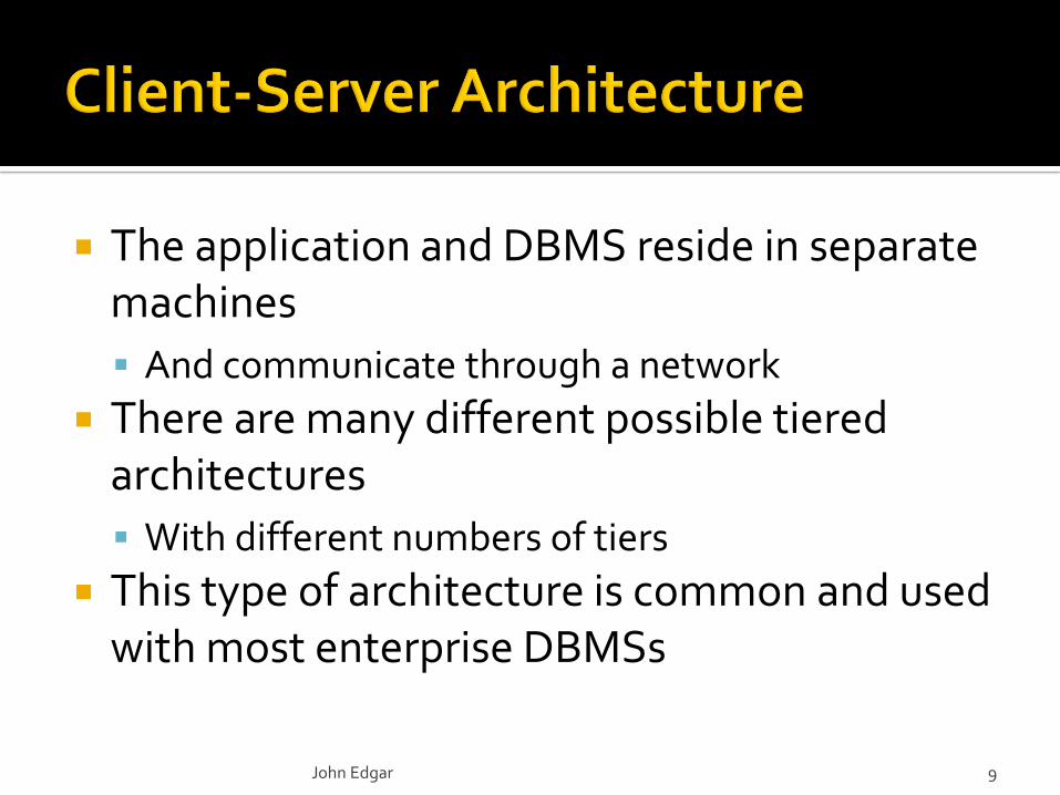
The application and DBMS reside in separate machines
And communicate through a network
There are many different possible tiered architectures
With different numbers of tiers
This type of architecture is common and used with most enterprise DBMSs
John Edgar 9
1.2
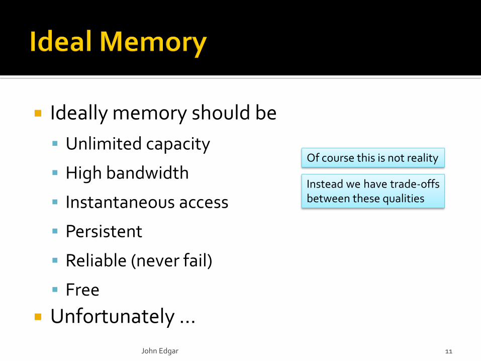
Ideally memory should be
Unlimited capacity
High bandwidth
Instantaneous access
Persistent
Reliable (never fail)
Free
Unfortunately …
John Edgar 11
Of course this is not reality
Instead we have trade-offsbetween these qualities

volatile
nonvolatile
main memory
John Edgar 12
registers
L1 cache
L2 cache
L3 cache
persistent memory
tape
flash (SSD)disk (HDD)
cost speed
1
1
3
15
access time (ns)
50
100
20,000
SRAM
DRAM
5,000,000
General interest: latency comparisons
10,000,000,000
a few blocks
distance (kms)
long commute to work
vancouver to capetown
6.5 round trips to the moon, tenth of the way to mars
33 round trips to the sun
Cost (and speed) change
Cost of all memory types hasdecreased
For newer technologies suchas SSD cost per MB hassubstantially decreased
The comparison ignoresbandwidth which generallyincreases down the hierarchy
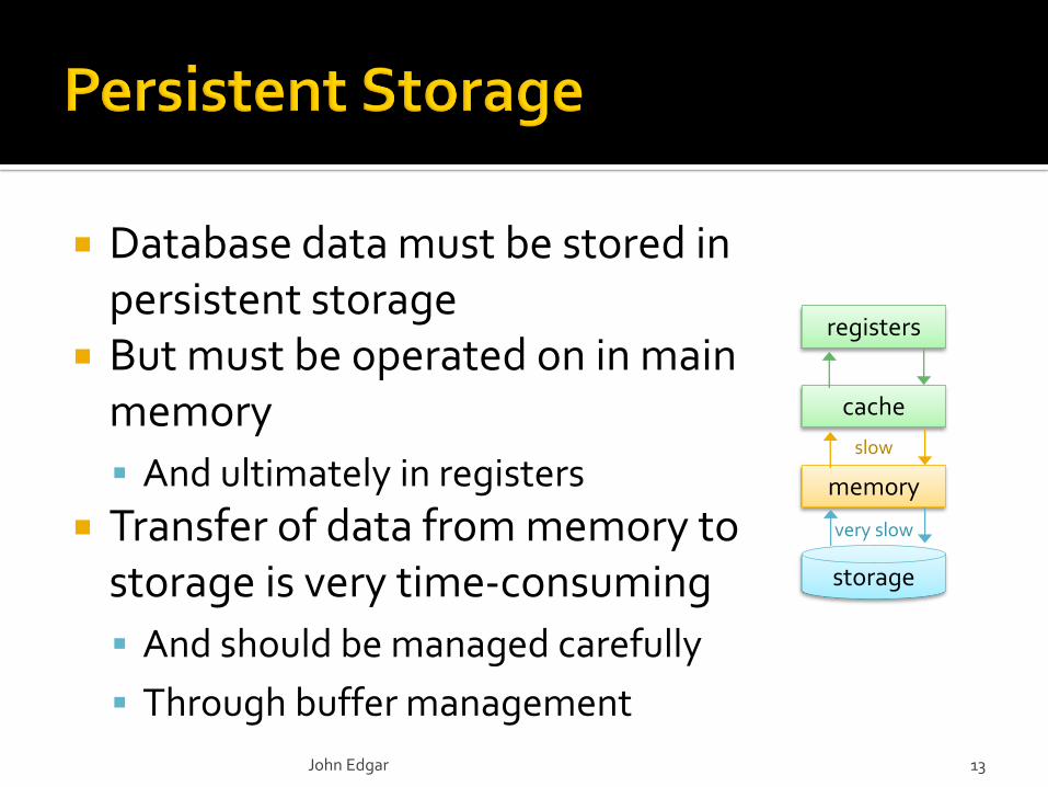
Database data must be stored in persistent storage
But must be operated on in main memory
And ultimately in registers
Transfer of data from memory to storage is very time-consuming
And should be managed carefully
Through buffer management
John Edgar 13
storage
memory
cache
registers
slow
very slow
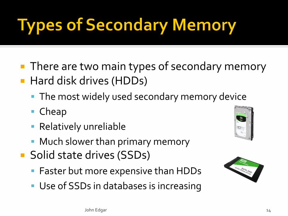
There are two main types of secondary memory Hard disk drives (HDDs)
The most widely used secondary memory device
Cheap
Relatively unreliable
Much slower than primary memory
Solid state drives (SSDs)
Faster but more expensive than HDDs
Use of SSDs in databases is increasing
John Edgar 14
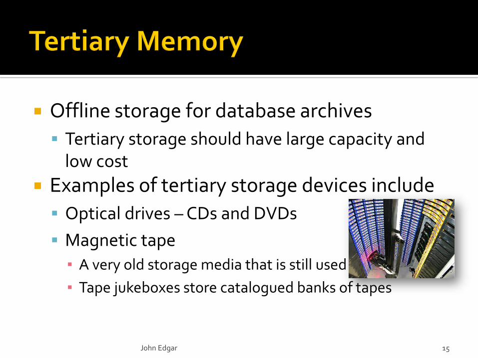
Offline storage for database archives
Tertiary storage should have large capacity and low cost
Examples of tertiary storage devices include
Optical drives – CDs and DVDs
Magnetic tape
▪ A very old storage media that is still used
▪ Tape jukeboxes store catalogued banks of tapes
John Edgar 15
Persistent memory is non-volatile RAM and is also known as NVM – non-volatile memory
NVRAM – non-volatile RAM
SCM – storage class memory Characteristics
Byte-addressable
Persistent There are different types
Varied speed, capacity and cost
John Edgar 16
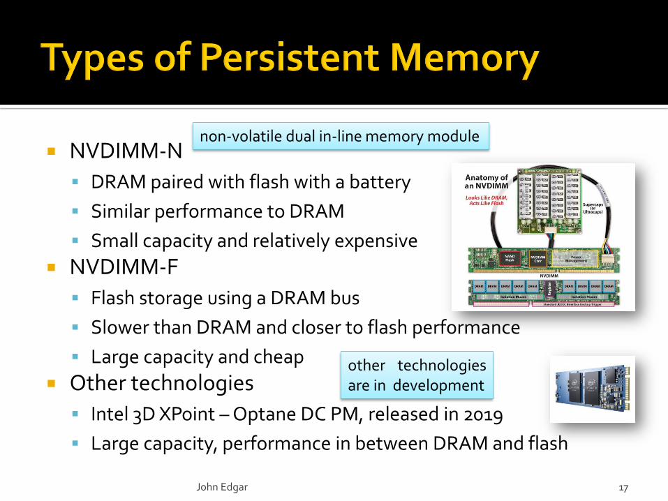
NVDIMM-N
DRAM paired with flash with a battery
Similar performance to DRAM
Small capacity and relatively expensive
NVDIMM-F
Flash storage using a DRAM bus
Slower than DRAM and closer to flash performance
Large capacity and cheap
Other technologies
Intel 3D XPoint – Optane DC PM, released in 2019
Large capacity, performance in between DRAM and flash
John Edgar 17
non-volatile dual in-line memory module
other technologiesare in development

Main memory assumed to be much smaller than persistent storage
Transaction processing occurs in main memory
DB resides in storage
▪ Data must be transferred between main memory and storage
Performance is primarily determined by storage access speed
Traditionally stored on HDDs
Transitioning to SSDs
John Edgar 18
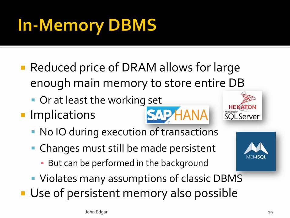
Reduced price of DRAM allows for large enough main memory to store entire DB
Or at least the working set
Implications
No IO during execution of transactions
Changes must still be made persistent
▪ But can be performed in the background
Violates many assumptions of classic DBMS
Use of persistent memory also possible
John Edgar 19
2.1
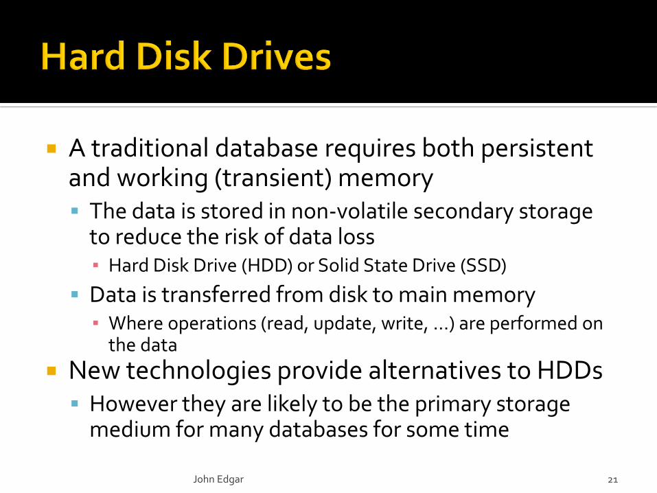
A traditional database requires both persistent and working (transient) memory The data is stored in non-volatile secondary storage
to reduce the risk of data loss▪ Hard Disk Drive (HDD) or Solid State Drive (SSD)
Data is transferred from disk to main memory▪ Where operations (read, update, write, …) are performed on
the data
New technologies provide alternatives to HDDs However they are likely to be the primary storage
medium for many databases for some time
John Edgar 21
John Edgar 22
surface
platters each has 2 surfaces
disk head array
disk head
for 1st surface
moves in and out
platters rotate
10,ooo rpm
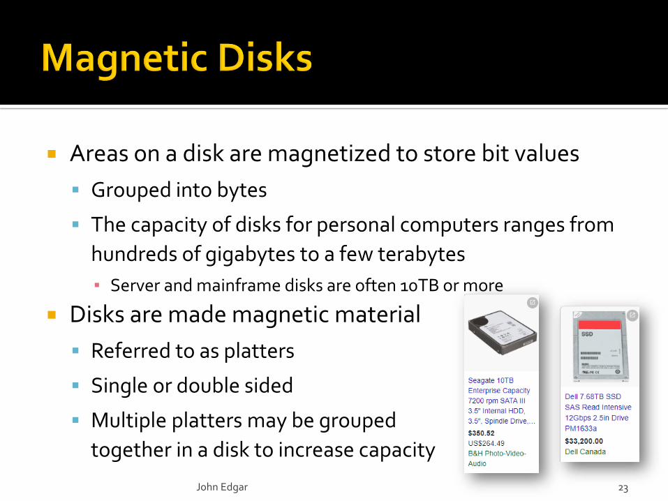
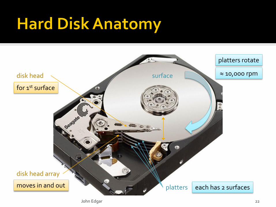
Areas on a disk are magnetized to store bit values
Grouped into bytes
The capacity of disks for personal computers ranges from
hundreds of gigabytes to a few terabytes
▪ Server and mainframe disks are often 10TB or more
Disks are made magnetic material
Referred to as platters
Single or double sided
Multiple platters may be grouped
together in a disk to increase capacity
John Edgar 23
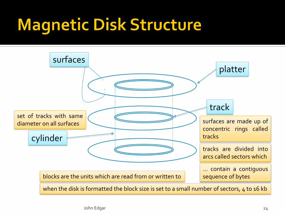
track
plattersurfaces
cylinder
John Edgar 24
surfaces are made up ofconcentric rings calledtracks
tracks are divided intoarcs called sectors which
… contain a contiguoussequence of bytes
when the disk is formatted the block size is set to a small number of sectors, 4 to 16 kb
blocks are the units which are read from or written to
set of tracks with samediameter on all surfaces
Block sizes vary Typically ranges from 512 to 8,192 bytes
Blocks are separated by fixed sized gaps▪ Which contain control information
Blocks can be addressed by cylinder number, surface number and block number In many modern disk drives a single Logical Block
Address (LBA) identifies a block▪ Which are numbered from 0 to block capacity – 1
Blocks map to pages A higher level abstraction
John Edgar 25
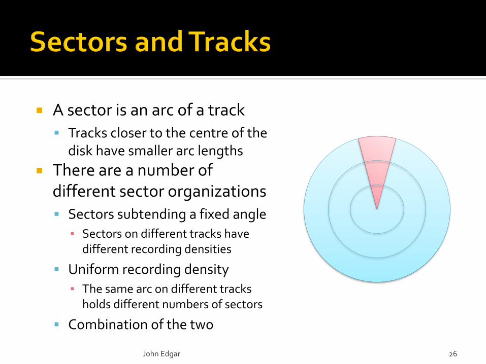
A sector is an arc of a track
Tracks closer to the centre of the disk have smaller arc lengths
There are a number of different sector organizations
Sectors subtending a fixed angle
▪ Sectors on different tracks have different recording densities
Uniform recording density
▪ The same arc on different tracks holds different numbers of sectors
Combination of the two
John Edgar 26
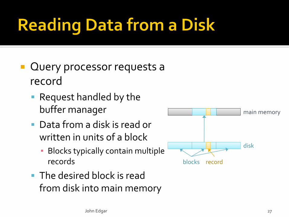
Query processor requests a record
Request handled by the buffer manager
Data from a disk is read or written in units of a block
▪ Blocks typically contain multiple records
The desired block is read from disk into main memory
John Edgar 27
blocks record
disk
main memory
read-modify-write cycle
no read-modify-write cycle
key
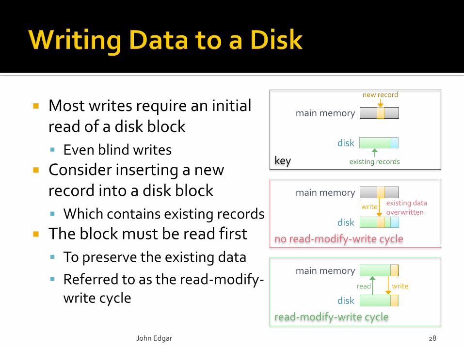
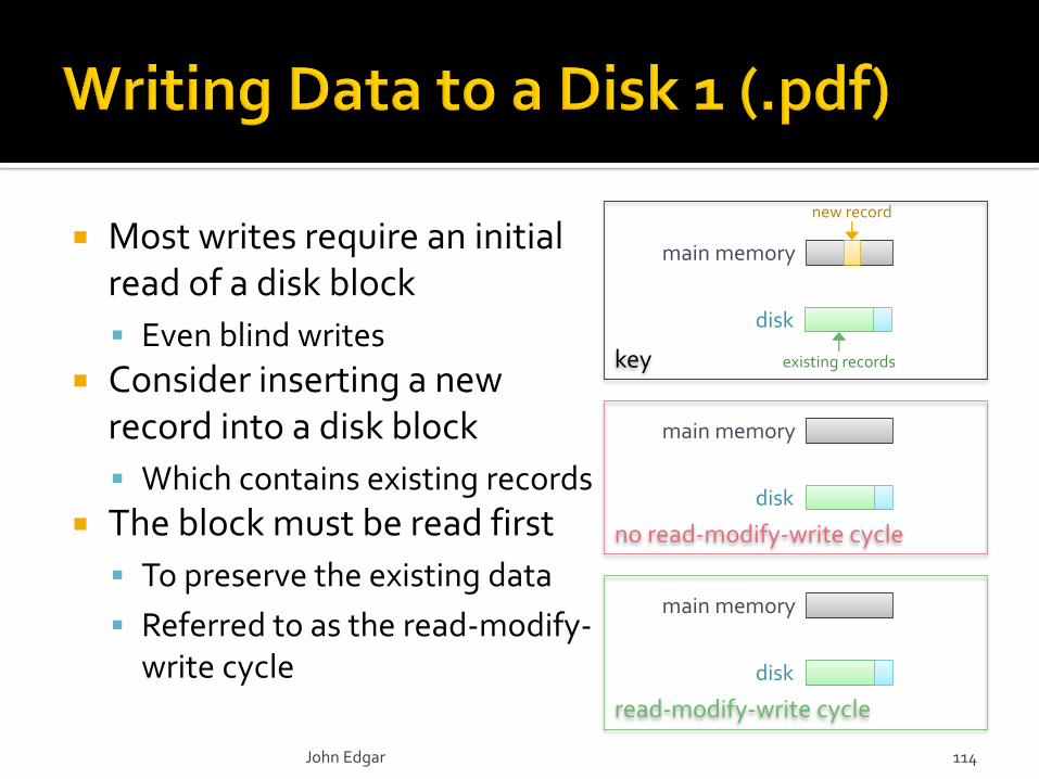
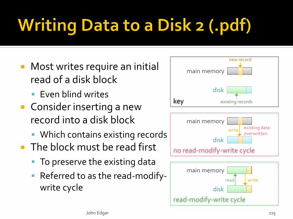
Most writes require an initial read of a disk block
Even blind writes
Consider inserting a new record into a disk block
Which contains existing records
The block must be read first
To preserve the existing data
Referred to as the read-modify-write cycle
John Edgar 28
disk
main memory
new record
existing records
disk
main memory
disk
main memory
existing data overwritten
read write
write
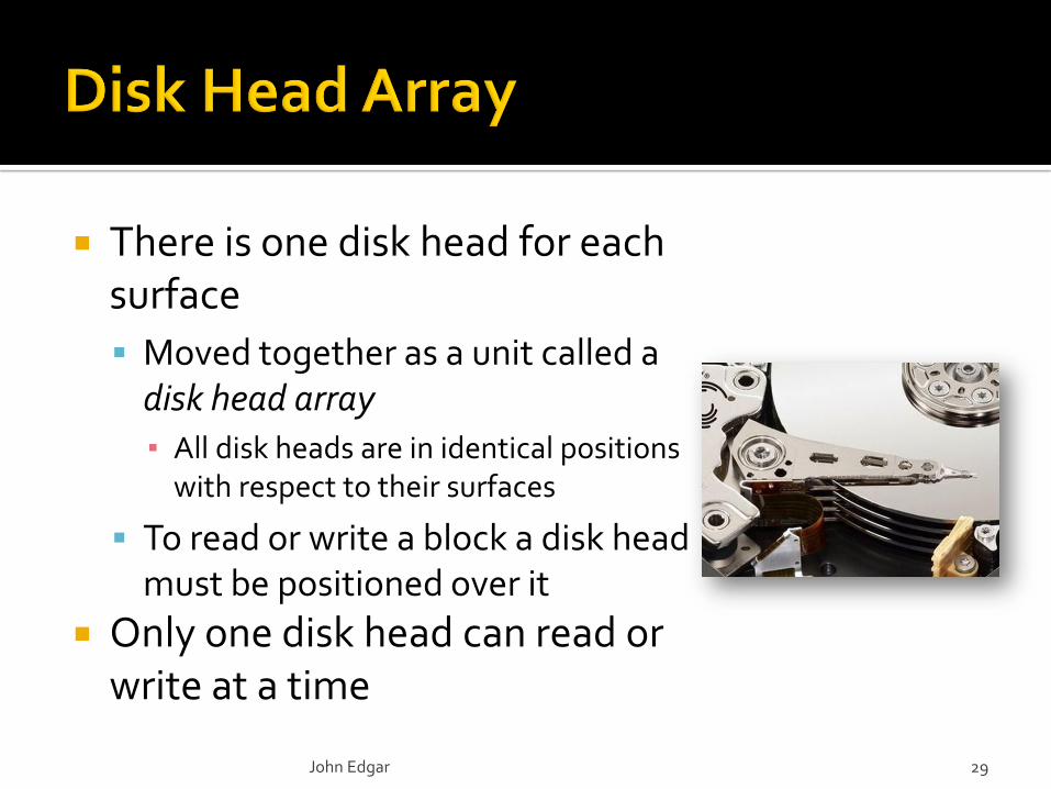
There is one disk head for each surface
Moved together as a unit called adisk head array
▪ All disk heads are in identical positions with respect to their surfaces
To read or write a block a disk head must be positioned over it
Only one disk head can read or write at a time
John Edgar 29

To access a block on a disk The disk head pivots over the
desired track▪ Seek time – average 4 to 10 ms
Wait for leading edge of block to reach the disk head▪ Rotational delay – derived from rpm
The desired block is read as it passes underneath the disk head▪ Transfer time – derived from rpm
Drive controlled by a processor Called the disk controller
The disk spins at a constant
speed
John Edgar 30
responsible for controlling the actuator, determiningwhen the disc has rotated to a sector, transferring data
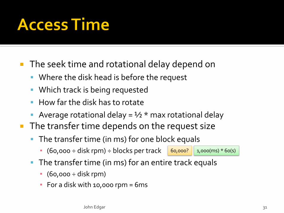
The seek time and rotational delay depend on
Where the disk head is before the request
Which track is being requested
How far the disk has to rotate
Average rotational delay = ½ * max rotational delay
The transfer time depends on the request size
The transfer time (in ms) for one block equals
▪ (60,000 ÷ disk rpm) ÷ blocks per track
The transfer time (in ms) for an entire track equals
▪ (60,000 ÷ disk rpm)
▪ For a disk with 10,000 rpm = 6ms
60,000? 1,000(ms) * 60(s)
John Edgar 31
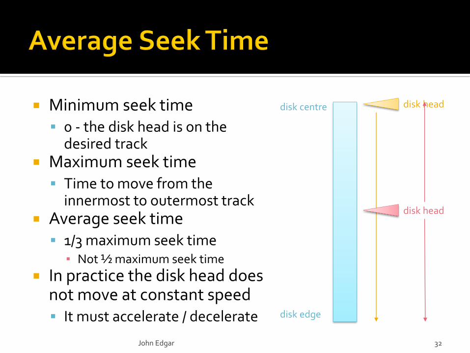
Minimum seek time 0 - the disk head is on the
desired track Maximum seek time
Time to move from the innermost to outermost track
Average seek time 1/3 maximum seek time
▪ Not ½ maximum seek time
In practice the disk head does not move at constant speed It must accelerate / decelerate
John Edgar 32
disk centre
disk edge
disk head
disk head
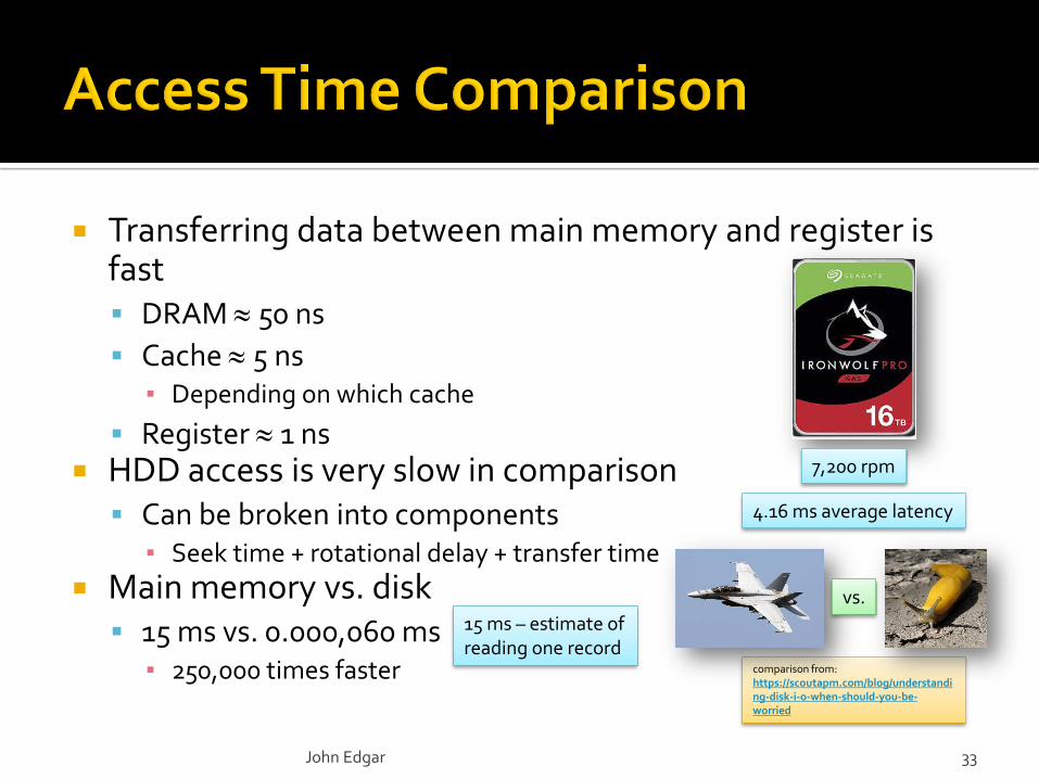
Transferring data between main memory and register is fast DRAM 50 ns
Cache 5 ns▪ Depending on which cache
Register 1 ns HDD access is very slow in comparison
Can be broken into components▪ Seek time + rotational delay + transfer time
Main memory vs. disk 15 ms vs. 0.000,060 ms
▪ 250,000 times faster
John Edgar 33
7,200 rpm
4.16 ms average latency
15 ms – estimate of reading one record
comparison from: https://scoutapm.com/blog/understanding-disk-i-o-when-should-you-be-worried
vs.
Disk access is slow
The largest components are seek time then rotational delay
Access two records in adjacent blocks on a track
Seek the track, rotate to first block, and transfer two blocks = 10 + 4 + 2*1 = 16ms
Accessing two records on different tracks
Seek the desired track, rotate to the block, and transfer the block, then repeat = (10 + 4 + 1)*2 = 30ms
Solution: store related data in close proximity
John Edgar 34
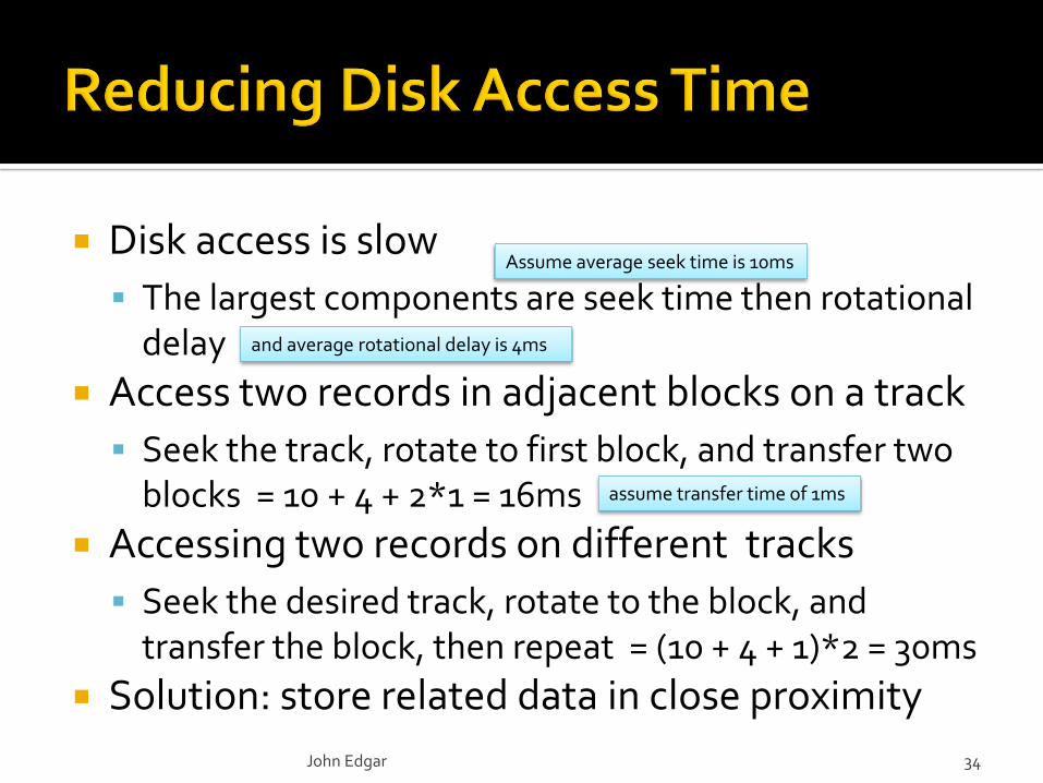
Assume average seek time is 10ms
and average rotational delay is 4ms
assume transfer time of 1ms
John Edgar 35
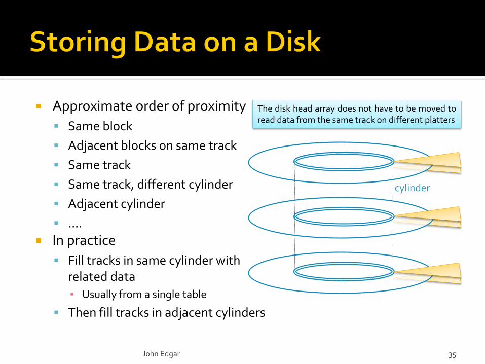
Approximate order of proximity
Same block
Adjacent blocks on same track
Same track
Same track, different cylinder
Adjacent cylinder
….
In practice
Fill tracks in same cylinder with related data
▪ Usually from a single table
Then fill tracks in adjacent cylinders
The disk head array does not have to be moved toread data from the same track on different platters
cylinder
The minimum unit of transfer of is a block
Multiple contiguous blocks may be transferred as a unit
▪ To a correspondingly sized main memory buffer
This is much faster than reading blocks one at a time
▪ Since seek time and rotational delay are only incurred once
Buffer management is important in reducing access time and includes
Prefetching
Double buffering
John Edgar 36
… discussed later …
Requests to read a block (or blocks) are processed in some order based on the disk scheduling algorithm
There are a variety of such algorithms
First-come-first served (FIFO)
Elevator and its variants▪ SCAN, LOOK, C-SCAN, C-LOOK, …
Shortest-seek
Goals
Reduce overall access time
Avoid starvation
John Edgar 37
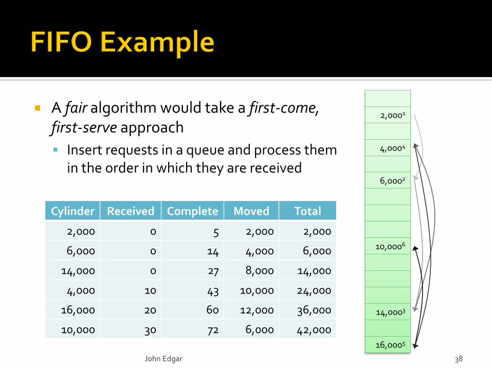
A fair algorithm would take a first-come, first-serve approach
Insert requests in a queue and process them in the order in which they are received
2,0001
4,0004
6,0002
10,0006
14,0003
16,0005
Cylinder Received Complete Moved Total
2,000 0 5 2,000 2,000
6,000 0 14 4,000 6,000
14,000 0 27 8,000 14,000
4,000 10 43 10,000 24,000
16,000 20 60 12,000 36,000
10,000 30 72 6,000 42,000
John Edgar 38
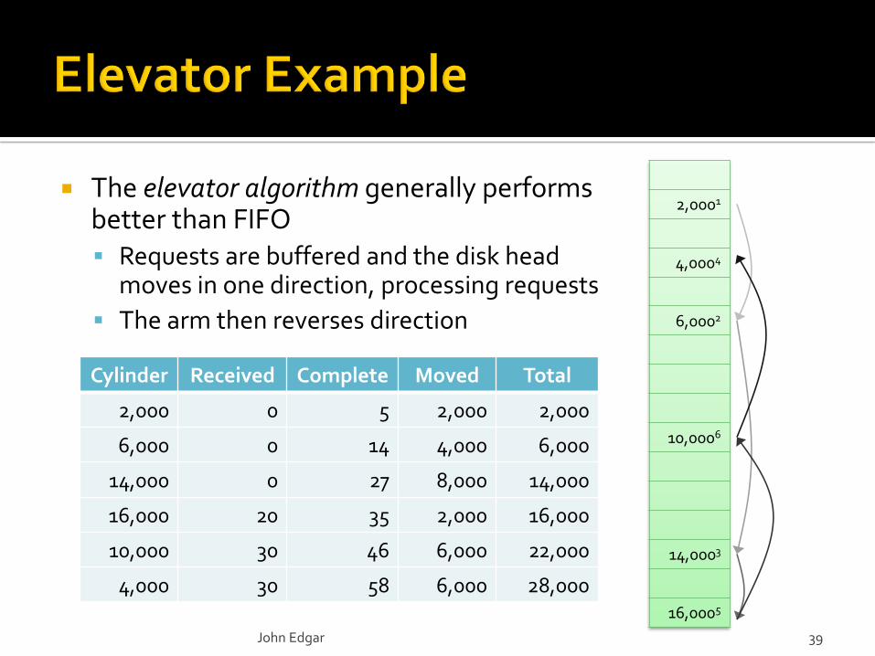
The elevator algorithm generally performs better than FIFO Requests are buffered and the disk head
moves in one direction, processing requests
The arm then reverses direction
2,0001
4,0004
6,0002
10,0006
14,0003
16,0005
Cylinder Received Complete Moved Total
2,000 0 5 2,000 2,000
6,000 0 14 4,000 6,000
14,000 0 27 8,000 14,000
16,000 20 35 2,000 16,000
10,000 30 46 6,000 22,000
4,000 30 58 6,000 28,000
John Edgar 39
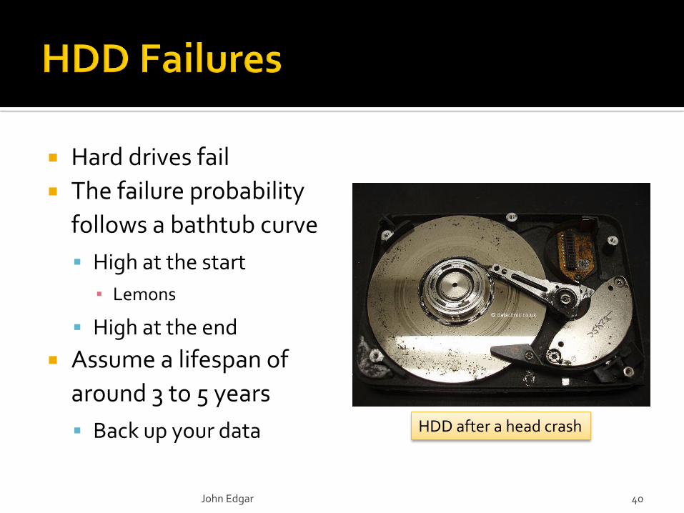
Hard drives fail
The failure probability
follows a bathtub curve
High at the start
▪ Lemons
High at the end
Assume a lifespan of
around 3 to 5 years
Back up your data
John Edgar 40
HDD after a head crash
Intermittent failure
Multiple attempts are required to read or write a sector
▪ Use checksums to check that incurred data has not been read
Media decay
A bit or a number of bits are permanently corrupted and it is impossible to read a sector
Write failure
A sector cannot be written to or retrieved
▪ Often caused by a power failure during a write
Disk crash
The entire disk becomes unreadable
John Edgar 41
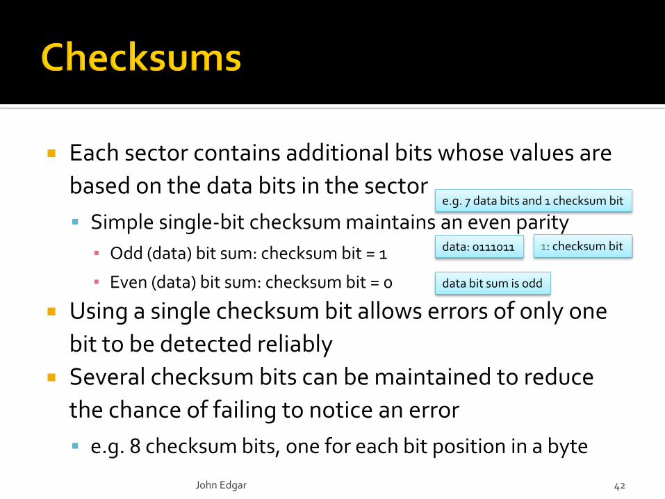
Each sector contains additional bits whose values are
based on the data bits in the sector
Simple single-bit checksum maintains an even parity
▪ Odd (data) bit sum: checksum bit = 1
▪ Even (data) bit sum: checksum bit = 0
Using a single checksum bit allows errors of only one
bit to be detected reliably
Several checksum bits can be maintained to reduce
the chance of failing to notice an error
e.g. 8 checksum bits, one for each bit position in a byte
John Edgar 42
e.g. 7 data bits and 1 checksum bit
data: 0111011
data bit sum is odd
1: checksum bit
Compared to main memory hard drives have two major problems
They are painfully slow
They are sadly unreliable
Both these issues are, to some extent, addressed by using RAID
Or by using SSDs
Or an in-memory database
John Edgar 43
… there is a certain amount of exaggeration going on here …

3.1
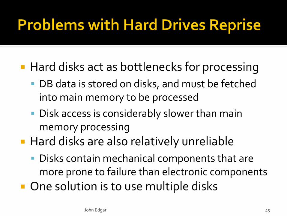
Hard disks act as bottlenecks for processing
DB data is stored on disks, and must be fetched into main memory to be processed
Disk access is considerably slower than main memory processing
Hard disks are also relatively unreliable
Disks contain mechanical components that are more prone to failure than electronic components
One solution is to use multiple disks
John Edgar 45
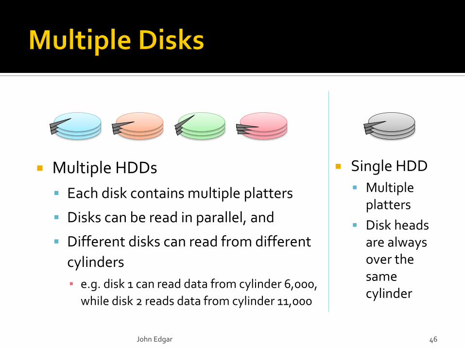
Single HDD
Multiple platters
Disk heads are always over the same cylinder
Multiple HDDs
Each disk contains multiple platters
Disks can be read in parallel, and
Different disks can read from different
cylinders
▪ e.g. disk 1 can read data from cylinder 6,000,
while disk 2 reads data from cylinder 11,000
John Edgar 46
A disk array gives the user the abstraction of a single large disk
When an I/O request is issued the physical disk blocks to be retrieved have to be identified
How the data is distributed over the disks in the array affects access time▪ And how many disks are involved in an I/O request
Data is divided into partitions called striping units
The striping unit is usually either a block or a bit
Striping units are distributed over the disks using a round robin algorithm
John Edgar 47
4 8 12 16 20 24 28 32 36 40 44 48 52 56 60 64 68 …
2 6 10 14 18 22 26 30 34 38 42 46 50 54 58 62 66 …
1 5 9 13 17 21 25 29 33 37 41 45 49 53 57 61 65 …
3 7 11 15 19 23 27 31 35 39 43 47 51 55 59 63 67 …
1 2 3 4 5 6 7 8 9 10 11 12 13 14 15 16 17 18 19 20 21 22 23 24 …
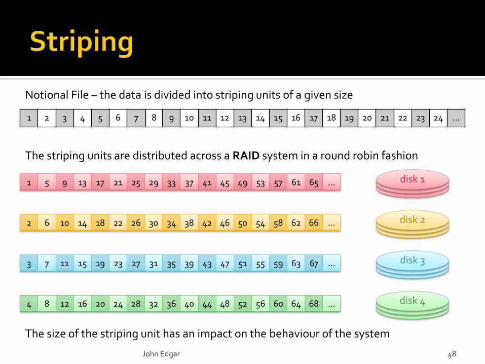
Notional File – the data is divided into striping units of a given size
The striping units are distributed across a RAID system in a round robin fashion
The size of the striping unit has an impact on the behaviour of the system
disk 1
disk 2
disk 3
disk 4
John Edgar 48
…
John Edgar 49
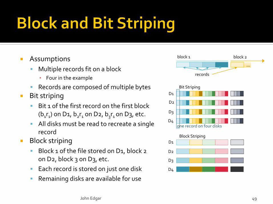
Assumptions
Multiple records fit on a block▪ Four in the example
Records are composed of multiple bytes
Bit striping
Bit 1 of the first record on the first block (b1r1) on D1, b2r1 on D2, b3r1 on D3, etc.
All disks must be read to recreate a single record
Block striping
Block 1 of the file stored on D1, block 2 on D2, block 3 on D3, etc.
Each record is stored on just one disk
Remaining disks are available for use
D1
records
block 1 block 2
D2
D3
D4
Bit Striping
D1
D2
D3
D4
Block Striping
one record on four disks
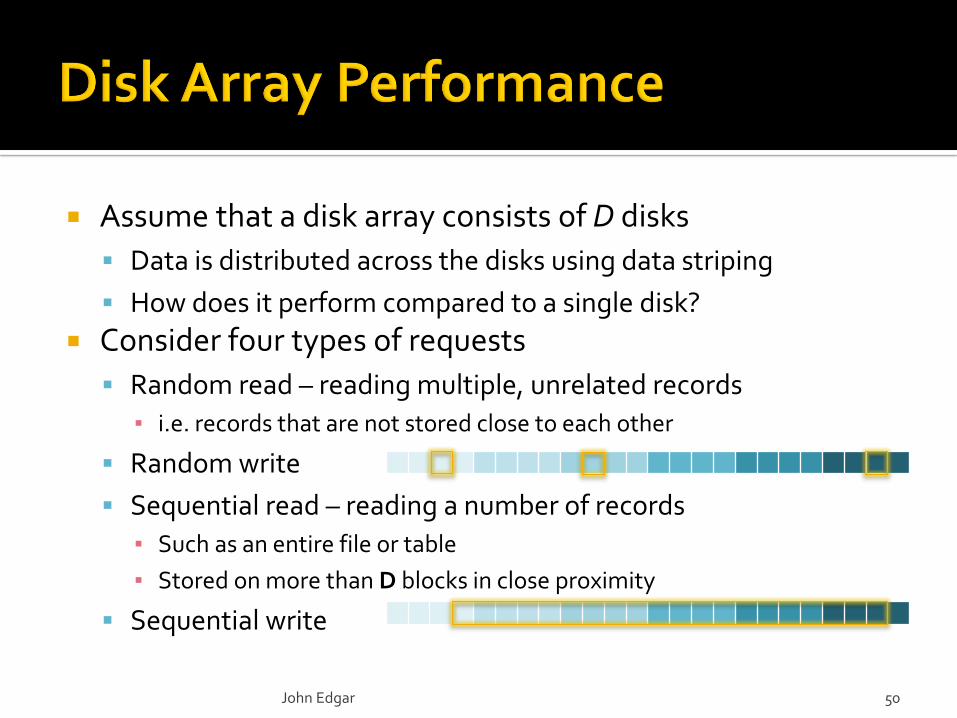
Assume that a disk array consists of D disks
Data is distributed across the disks using data striping
How does it perform compared to a single disk?
Consider four types of requests
Random read – reading multiple, unrelated records
▪ i.e. records that are not stored close to each other
Random write
Sequential read – reading a number of records
▪ Such as an entire file or table
▪ Stored on more than D blocks in close proximity
Sequential write
John Edgar 50
Use all D disks to improve efficiency, and distribute data
using block striping
Random reads and writes
Up to D different records can be read from or written to at once
▪ Depending on which disks the records reside on
▪ Records might reside on different disks, or – if unlucky – all on the
same disk
Sequential reads and writes
Related data are distributed over all D disks so performance is D
times faster than a single disk
Writes generally entail reading the data first
John Edgar 51
But what about reliability …
The standard hard drive failures measure is MTBF, expressed in hours
Annualized Failure Rate (AFR) expresses the probability per year a drive will fail
▪ AFR 8766 / MTBF
Modern enterprise hard drives have MTBF values of around 1,000,000
Consumer quality drives are around half these values
Hard drive reliability has increased substantially over time
MTBF values are usually published by manufacturers
And should be assumed to give a flattering picture of a drive's reliability
John Edgar 52
8766? average number of hours in a year
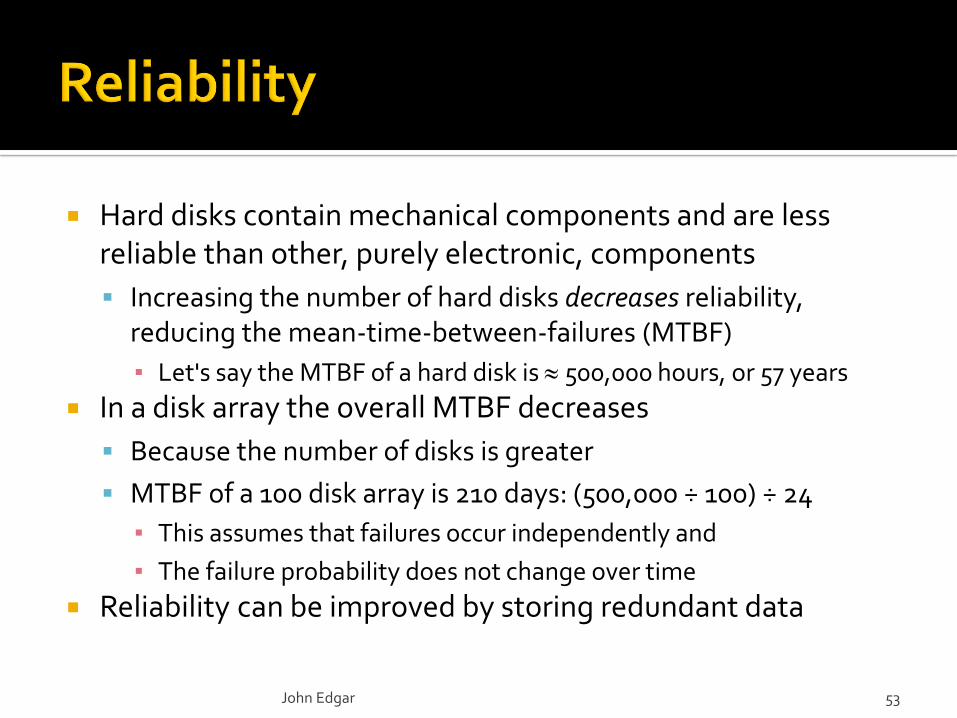
Hard disks contain mechanical components and are less reliable than other, purely electronic, components
Increasing the number of hard disks decreases reliability, reducing the mean-time-between-failures (MTBF)
▪ Let's say the MTBF of a hard disk is 500,000 hours, or 57 years
In a disk array the overall MTBF decreases
Because the number of disks is greater
MTBF of a 100 disk array is 210 days: (500,000 ÷ 100) ÷ 24
▪ This assumes that failures occur independently and
▪ The failure probability does not change over time
Reliability can be improved by storing redundant data
John Edgar 53
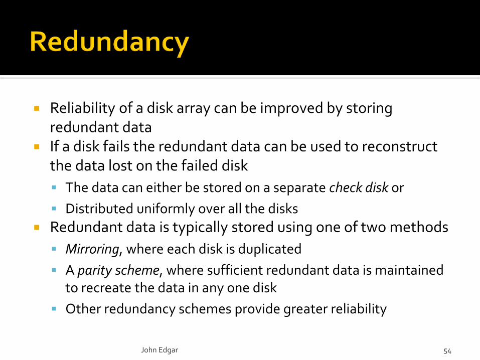
Reliability of a disk array can be improved by storing redundant data
If a disk fails the redundant data can be used to reconstruct the data lost on the failed disk
The data can either be stored on a separate check disk or
Distributed uniformly over all the disks
Redundant data is typically stored using one of two methods
Mirroring, where each disk is duplicated
A parity scheme, where sufficient redundant data is maintained to recreate the data in any one disk
Other redundancy schemes provide greater reliability
John Edgar 54

For each bit on the data disks there is a parity bit on a check disk
If the sum of the data disks bits is even the parity bit is set to zero
If the sum of the bits is odd the parity bit is set to one
The data on any one failed disk can be recreated bit by bit
0 1 1 0 0 0 1 0 0 1 0 1 0 0 1 0 0 1 0 1 0 0 1 1 …
1 0 1 0 1 0 1 0 1 0 1 0 1 0 0 1 1 0 0 1 0 1 0 0 …
0 1 1 0 1 1 1 1 0 0 1 1 0 0 1 0 1 1 0 1 1 0 0 1 …
0 0 0 1 1 1 0 1 0 0 1 1 0 0 0 1 1 0 1 1 1 0 0 1 …
1 0 1 1 1 0 1 0 1 1 1 1 1 0 0 0 1 0 1 0 0 1 1 1 …
Corresponding bytes of the system's check disk
First threebytes of data disks in a four (data) disk RAID system
John Edgar 55
Reading – not affected by parity
data
Writing - either
calculate new value of the parity
bit from all the data disks or
flip parity bit if corresponding
data bit has changed
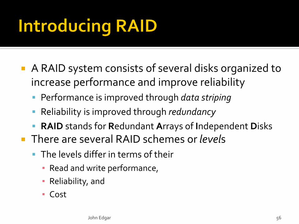
A RAID system consists of several disks organized to increase performance and improve reliability
Performance is improved through data striping
Reliability is improved through redundancy
RAID stands for Redundant Arrays of Independent Disks
There are several RAID schemes or levels
The levels differ in terms of their
▪ Read and write performance,
▪ Reliability, and
▪ Cost
John Edgar 56
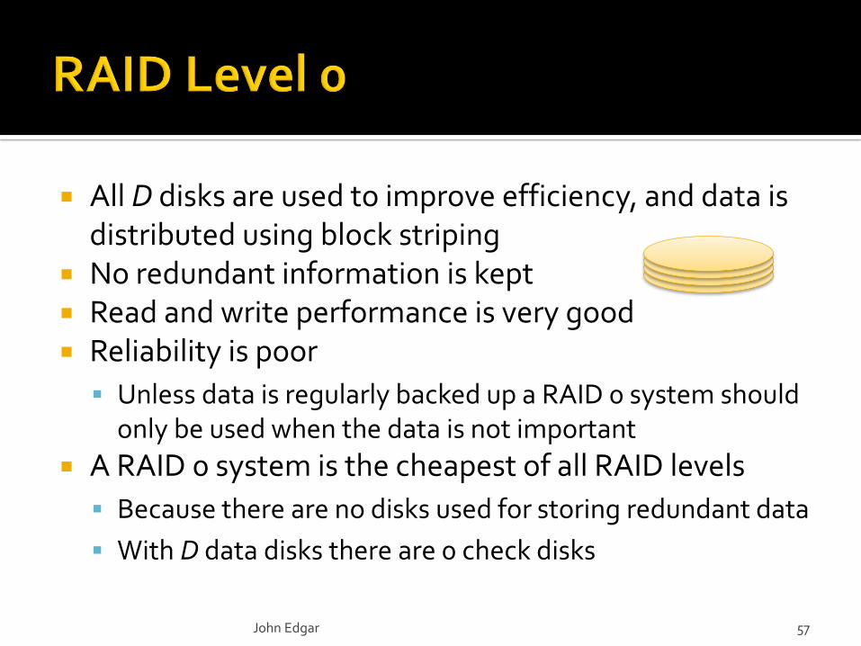
All D disks are used to improve efficiency, and data is distributed using block striping
No redundant information is kept Read and write performance is very good Reliability is poor
Unless data is regularly backed up a RAID 0 system should only be used when the data is not important
A RAID 0 system is the cheapest of all RAID levels
Because there are no disks used for storing redundant data
With D data disks there are 0 check disks
John Edgar 57
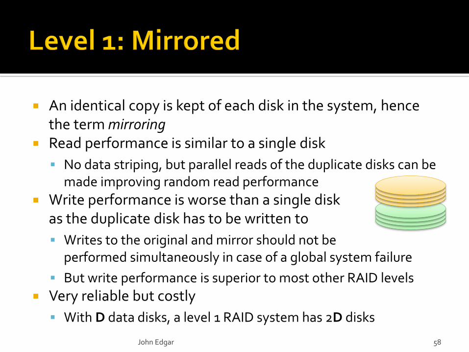
An identical copy is kept of each disk in the system, hence the term mirroring
Read performance is similar to a single disk
No data striping, but parallel reads of the duplicate disks can be made improving random read performance
Write performance is worse than a single disk as the duplicate disk has to be written to
Writes to the original and mirror should not be performed simultaneously in case of a global system failure
But write performance is superior to most other RAID levels
Very reliable but costly
With D data disks, a level 1 RAID system has 2D disks
John Edgar 58
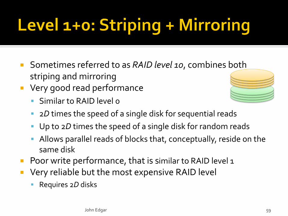
Sometimes referred to as RAID level 10, combines both striping and mirroring
Very good read performance
Similar to RAID level 0
2D times the speed of a single disk for sequential reads
Up to 2D times the speed of a single disk for random reads
Allows parallel reads of blocks that, conceptually, reside on the same disk
Poor write performance, that is similar to RAID level 1
Very reliable but the most expensive RAID level Requires 2D disks
John Edgar 59
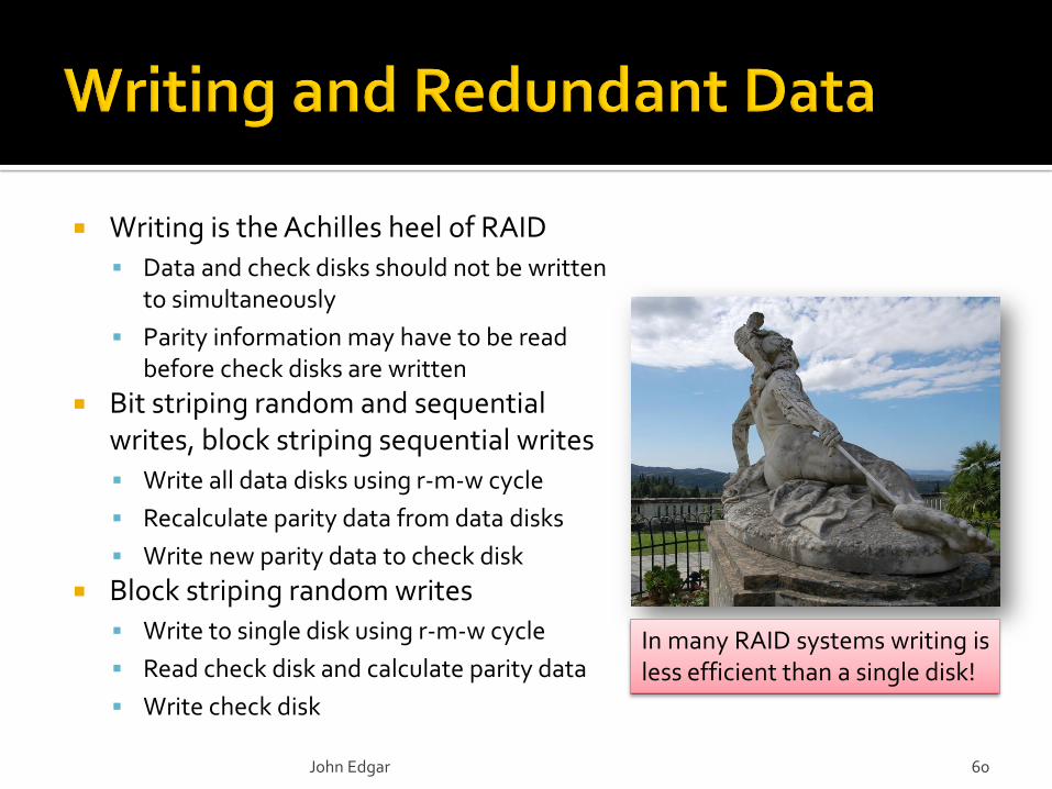
Writing is the Achilles heel of RAID
Data and check disks should not be written to simultaneously
Parity information may have to be read before check disks are written
Bit striping random and sequential writes, block striping sequential writes
Write all data disks using r-m-w cycle
Recalculate parity data from data disks
Write new parity data to check disk
Block striping random writes
Write to single disk using r-m-w cycle
Read check disk and calculate parity data
Write check disk
John Edgar 60
In many RAID systems writing isless efficient than a single disk!
A RAID system with D disks can read data up to D times faster than a single disk system
For sequential reads there is no performance difference between bit striping and block striping
Block striping is more efficient for random reads With bit striping all D disks have to be read to recreate a single record
(and block) of the data file
With block striping a complete record is stored on one disk therefore only that one disk is required to satisfy a random read
Write performance is similar except that it is affected by the parity scheme Random writes are typically inefficient
John Edgar 61

Level 2 – Memory Style Error Correcting Code
The striping unit is a single bit
Uses a scheme that allows the failed disk to be identified
▪ Which increases the number of disks required
Modern disk controllers can detect a failed disk so this is unnecessary
Can only tolerate the loss of a single disk
Level 3 – Byte Interleaved Parity
The striping unit is a byte
Random read and write performance is poor as all disks have to be accessed for each request
Can tolerate the loss of a single disk
Requires D + 1 disks
John Edgar 62
Uses block striping to distribute data over disks Uses one redundant disk containing parity data
The ith block on the redundant disk contains parity checks for the ith blocks of all data disks
Good sequential read performance
D times single disk speed Very good random read performance
Disks can be read independently therefore up to Dtimes single disk speed
John Edgar 63
Cost is moderate
Only one check disk is required
The system can tolerate the loss of one drive Write performance is poor for random writes
In which different data disks are written independently
For each such write a write to the redundant disk is also required
Performance can be improved by distributing the redundant data across all disks – RAID level 5
John Edgar 64
The dedicated check disk in RAID level 4 tends to act as a bottleneck for random writes
RAID level 5 does not have a dedicated check disk but distributes the parity data across all disks
Increasing the performance of random writes
Read performance is marginally improved
Sequential read and write performance is similar to level 4
Cost is moderate, with the same effective space utilization as level 4
The system can tolerate the loss of one drive
John Edgar 65
RAID levels 4 and 5 can only cope with single disk crashes
If multiple disks crash at the same time data will be lost
It is unlikely that two disks will fail at the same time
At least, by coincidence
Replacing a disk is time consuming
Therefore it is possible that a second disk may fail during the rebuilding process
RAID level 6 allows systems to deal with multiple disk crashes
John Edgar 66

RAID level 6 records two sets of parity data for each set of bits across all disks
Using two different parity schemes
The system requires at least 4 disks
▪ In a 4 disk system half of the data is parity data
▪ As the number of disks increases the percentage of redundant data decreases
The redundancy data allows a system to recover from two simultaneous disk crashes
John Edgar 67
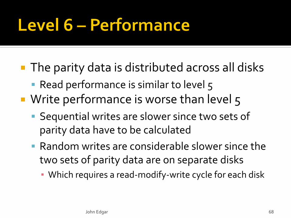
The parity data is distributed across all disks
Read performance is similar to level 5
Write performance is worse than level 5
Sequential writes are slower since two sets of parity data have to be calculated
Random writes are considerable slower since the two sets of parity data are on separate disks
▪ Which requires a read-modify-write cycle for each disk
John Edgar 68
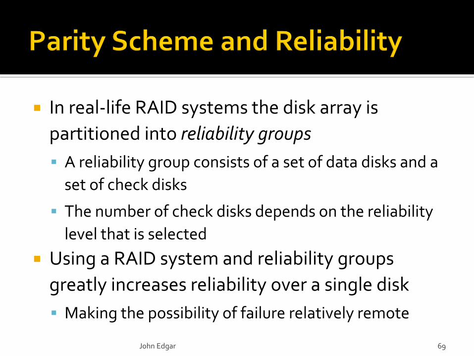
In real-life RAID systems the disk array is
partitioned into reliability groups
A reliability group consists of a set of data disks and a
set of check disks
The number of check disks depends on the reliability
level that is selected
Using a RAID system and reliability groups
greatly increases reliability over a single disk
Making the possibility of failure relatively remote
John Edgar 69
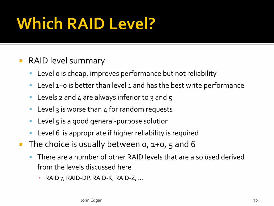
RAID level summary
Level 0 is cheap, improves performance but not reliability
Level 1+0 is better than level 1 and has the best write performance
Levels 2 and 4 are always inferior to 3 and 5
Level 3 is worse than 4 for random requests
Level 5 is a good general-purpose solution
Level 6 is appropriate if higher reliability is required
The choice is usually between 0, 1+0, 5 and 6
There are a number of other RAID levels that are also used derived
from the levels discussed here
▪ RAID 7, RAID-DP, RAID-K, RAID-Z, …
John Edgar 70

4.1
John Edgar 72
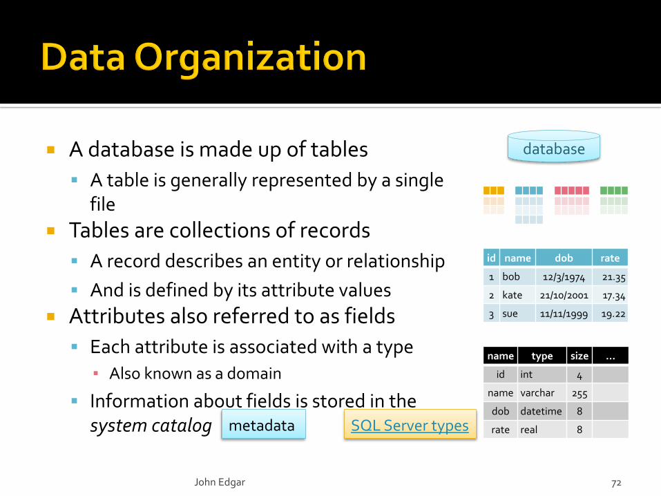
database A database is made up of tables
A table is generally represented by a single file
Tables are collections of records
A record describes an entity or relationship
And is defined by its attribute values
Attributes also referred to as fields
Each attribute is associated with a type
▪ Also known as a domain
Information about fields is stored in the system catalog
id name dob rate
1 bob 12/3/1974 21.35
2 kate 21/10/2001 17.34
3 sue 11/11/1999 19.22
metadata
name type size …
id int 4
name varchar 255
dob datetime 8
rate real 8SQL Server types
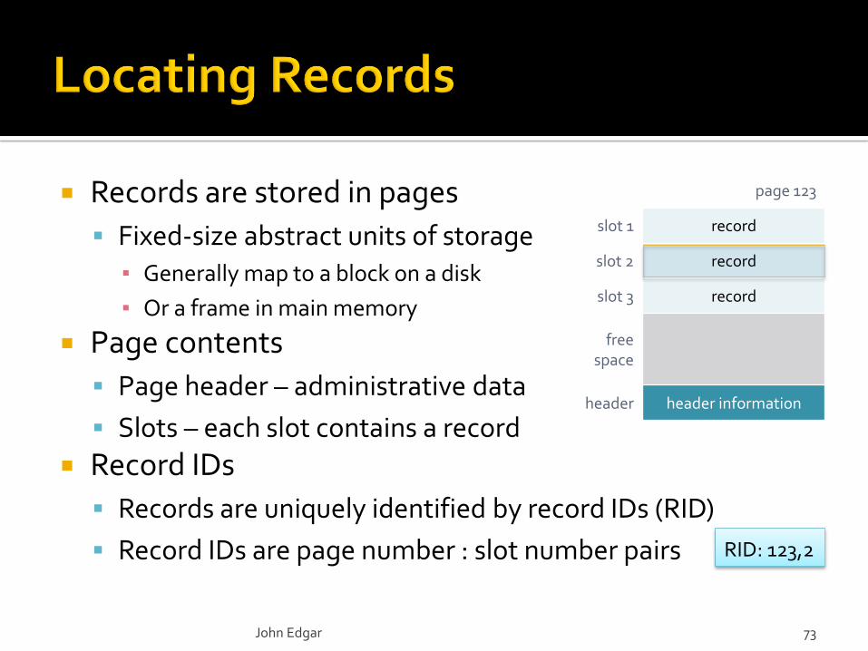
Records are stored in pages
Fixed-size abstract units of storage▪ Generally map to a block on a disk
▪ Or a frame in main memory
Page contents
Page header – administrative data
Slots – each slot contains a record
Record IDs
Records are uniquely identified by record IDs (RID)
Record IDs are page number : slot number pairs
John Edgar 73
page 123
slot 1 record
slot 2 record
slot 3 record
free space
header header information
RID: 123,2

Records are either fixed or variable length
Fixed length records have some important advantages
▪ Easier to rearrange records
▪ Less overhead for header data
▪ More efficient search
Fixed length records
Both the number of fields and the field length is fixed
Given the address of a record a field can be found
▪ By referring to the field size in the system catalog
This format is sometimes referred to as relative location
John Edgar 74
header field 1 field 2 field 3 … field n
e.g. find field 3 = base address + size(field1) + size (field2)
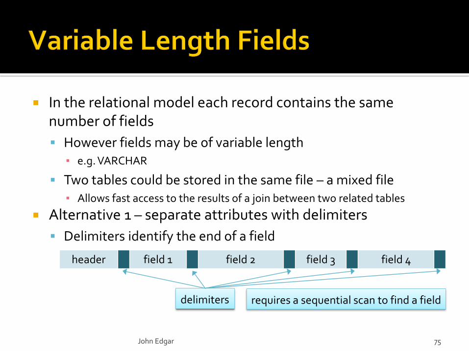
In the relational model each record contains the same number of fields
However fields may be of variable length▪ e.g. VARCHAR
Two tables could be stored in the same file – a mixed file▪ Allows fast access to the results of a join between two related tables
Alternative 1 – separate attributes with delimiters
Delimiters identify the end of a field
John Edgar 75
header field 1 field 2 field 3 field 4
delimiters requires a sequential scan to find a field

There are other alternatives for recording variable length records
Store additional data in the record header An array containing the length of each field
▪ Or just the lengths of the variable length fields, then store all fixed length fields first
Allows fields to be found by an offset calculation
If a record contains a variable number of fields other organizations may be used
Pointers to a list of fields▪ e.g. a mixed file
Preceding the attribute by the attribute identifier
John Edgar 76
Variable length field sizes may grow / shrink
Gets smaller – wastes space
Gets larger – may not fit in its slot, or in its page, or may even exceed the page size
Some data types may not fit on a single page
Large object data▪ Text, images, video, sound, …
LOB data is stored as either binary or character data
BLOB – unstructured binary data
CLOB, NCLOB – character data
BFILE – unstructured binary data in OS files
LOB data types store and manipulate large blocks of unstructured data
The maximum size of a LOB is large
▪ At least 8 terabytes in Oracle 10g
LOB data must be processed by application programs
John Edgar 77
LOB's have to be stored on a sequence of pages
Ideally the pages should be contiguous for efficient retrieval, or
Store the LOB on a linked list of blocks
▪ Where each block contains a pointer to the next block
If fast retrieval of LOBs is required they can be striped across multiple disks for parallel access
It may be necessary to provide an index to a LOB
For example indexing by seconds for a movie to allow a client to request small portions of the movie
John Edgar 78
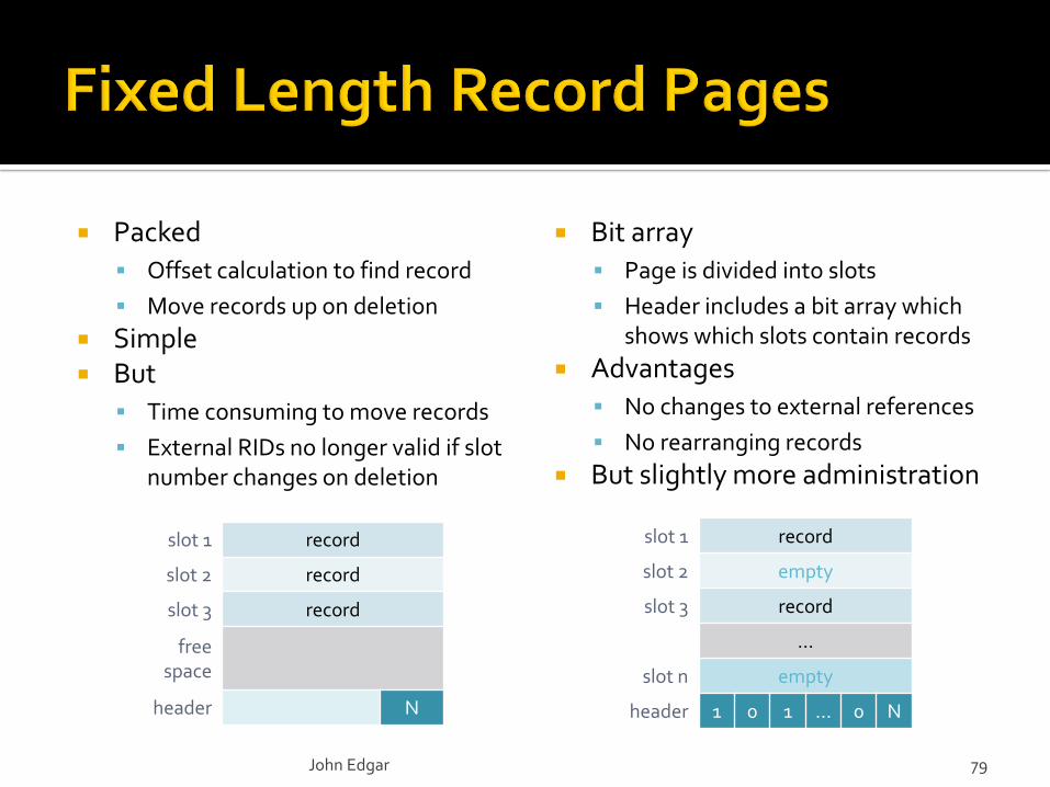
Packed
Offset calculation to find record
Move records up on deletion
Simple But
Time consuming to move records
External RIDs no longer valid if slot number changes on deletion
Bit array
Page is divided into slots
Header includes a bit array which shows which slots contain records
Advantages
No changes to external references
No rearranging records
But slightly more administration
John Edgar 79
slot 1 record
slot 2 record
slot 3 record
free space
header N
slot 1 record
slot 2 empty
slot 3 record
…
slot n empty
header 1 0 1 … 0 N

free space
16 … 24 20 N
N 2 1
slot directory
Maintain a slot directory
Each entry is a pair
▪ Record offset
▪ Record length
Records can be moved
without affecting RID
By modifying the slot entry
Flexible
But more complex than
fixed record organization
John Edgar 80
length = 24
length = 16
length = 20
4.2
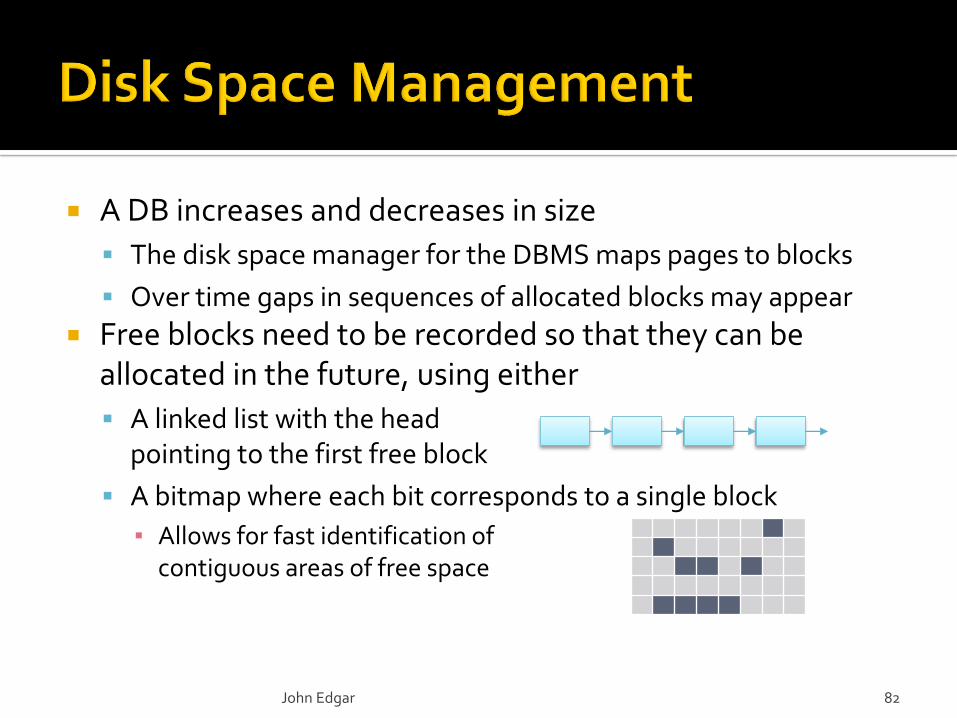
A DB increases and decreases in size
The disk space manager for the DBMS maps pages to blocks
Over time gaps in sequences of allocated blocks may appear
Free blocks need to be recorded so that they can be allocated in the future, using either
A linked list with the head pointing to the first free block
A bitmap where each bit corresponds to a single block
▪ Allows for fast identification of contiguous areas of free space
John Edgar 82
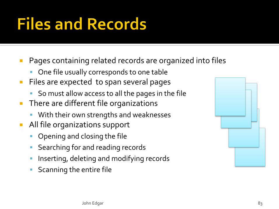
Pages containing related records are organized into files
One file usually corresponds to one table
Files are expected to span several pages
So must allow access to all the pages in the file
There are different file organizations
With their own strengths and weaknesses
All file organizations support
Opening and closing the file
Searching for and reading records
Inserting, deleting and modifying records
Scanning the entire file
John Edgar 83
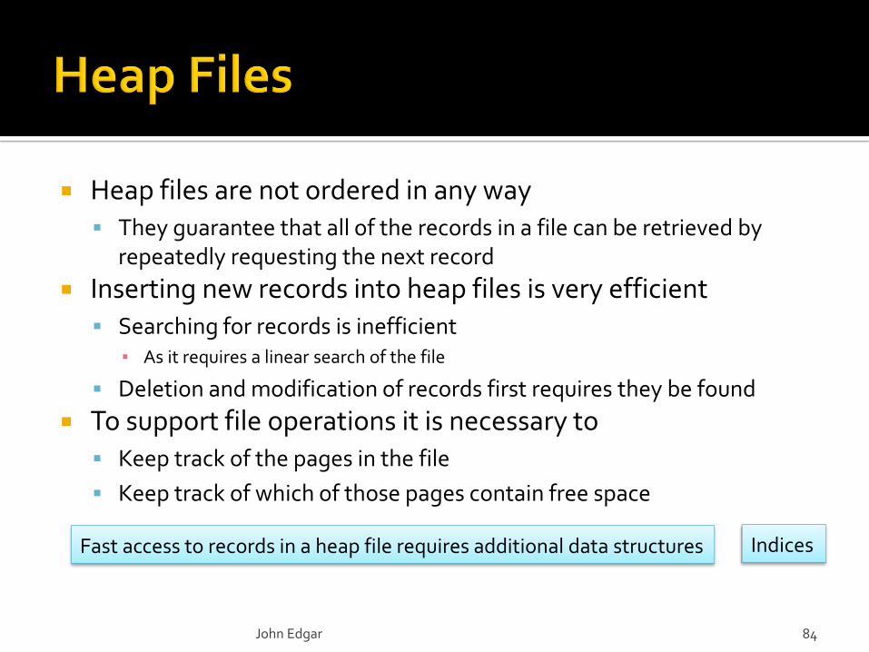
Heap files are not ordered in any way They guarantee that all of the records in a file can be retrieved by
repeatedly requesting the next record
Inserting new records into heap files is very efficient Searching for records is inefficient
▪ As it requires a linear search of the file
Deletion and modification of records first requires they be found
To support file operations it is necessary to Keep track of the pages in the file
Keep track of which of those pages contain free space
John Edgar 84
Fast access to records in a heap file requires additional data structures Indices
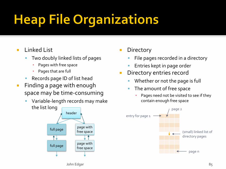
Linked List
Two doubly linked lists of pages▪ Pages with free space
▪ Pages that are full
Records page ID of list head
Finding a page with enough space may be time-consuming
Variable-length records may make the list long
Directory
File pages recorded in a directory
Entries kept in page order
Directory entries record
Whether or not the page is full
The amount of free space▪ Pages need not be visited to see if they
contain enough free space
John Edgar 85
page with free space
header
full page
full pagepage with free space
entry for page 1
page 2
page n
(small) linked list of directory pages
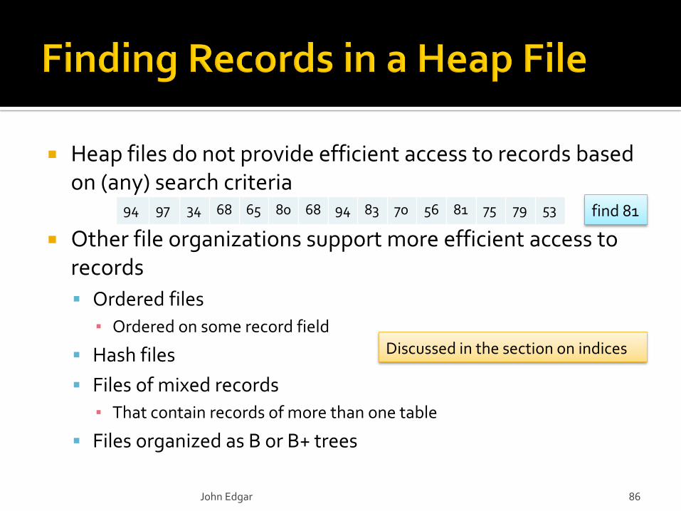
Heap files do not provide efficient access to records based on (any) search criteria
Other file organizations support more efficient access to records
Ordered files
▪ Ordered on some record field
Hash files
Files of mixed records
▪ That contain records of more than one table
Files organized as B or B+ trees
John Edgar 86
94 97 34 68 65 80 68 94 83 70 56 81 75 79 53 find 81
Discussed in the section on indices
5.1
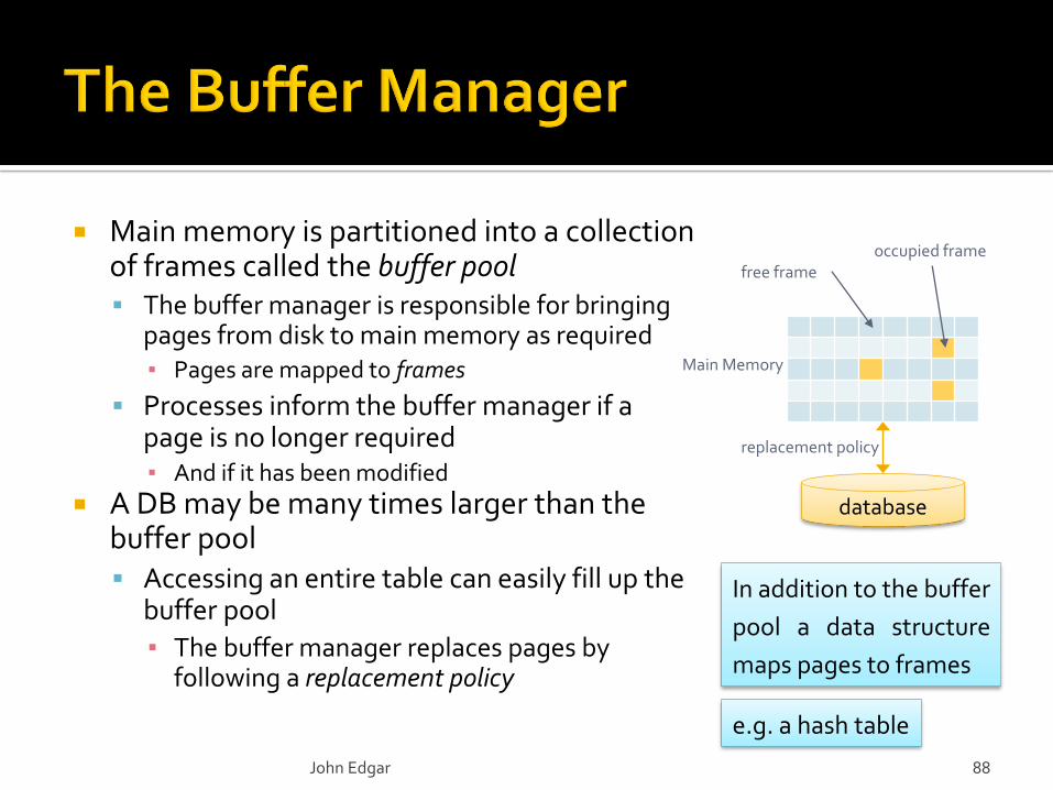
Main memory is partitioned into a collection of frames called the buffer pool The buffer manager is responsible for bringing
pages from disk to main memory as required▪ Pages are mapped to frames
Processes inform the buffer manager if a page is no longer required ▪ And if it has been modified
A DB may be many times larger than the buffer pool Accessing an entire table can easily fill up the
buffer pool
▪ The buffer manager replaces pages by following a replacement policy
John Edgar 88
database
replacement policy
free frameoccupied frame
Main Memory
In addition to the buffer
pool a data structure
maps pages to frames
e.g. a hash table
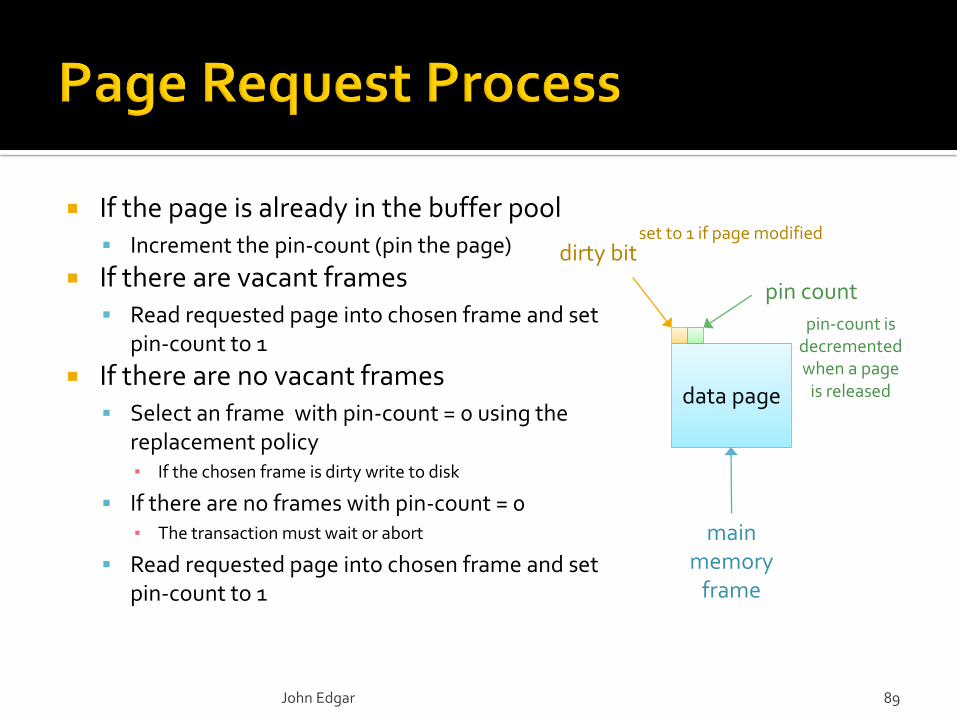
If the page is already in the buffer pool Increment the pin-count (pin the page)
If there are vacant frames Read requested page into chosen frame and set
pin-count to 1
If there are no vacant frames Select an frame with pin-count = 0 using the
replacement policy▪ If the chosen frame is dirty write to disk
If there are no frames with pin-count = 0▪ The transaction must wait or abort
Read requested page into chosen frame and set pin-count to 1
data page
mainmemory
frame
dirty bit
pin count
John Edgar 89
set to 1 if page modified
pin-count is decremented when a page
is released
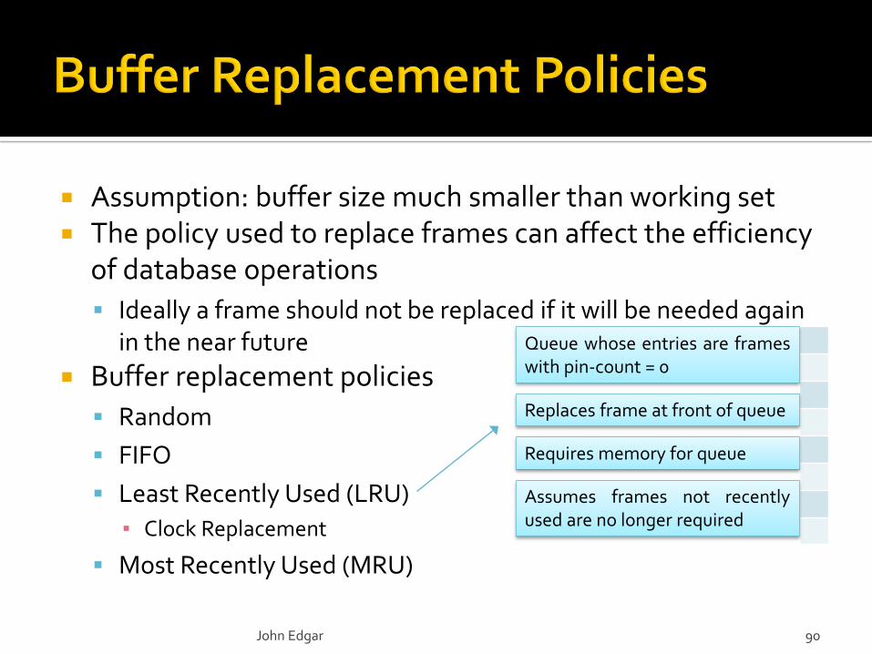
Assumption: buffer size much smaller than working set The policy used to replace frames can affect the efficiency
of database operations
Ideally a frame should not be replaced if it will be needed again in the near future
Buffer replacement policies
Random
FIFO
Least Recently Used (LRU)
▪ Clock Replacement
Most Recently Used (MRU)
John Edgar 90
Queue whose entries are frameswith pin-count = 0
Replaces frame at front of queue
Requires memory for queue
Assumes frames not recentlyused are no longer required
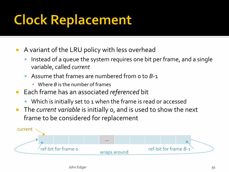
A variant of the LRU policy with less overhead
Instead of a queue the system requires one bit per frame, and a single variable, called current
Assume that frames are numbered from 0 to B-1
▪ Where B is the number of frames
Each frame has an associated referenced bit
Which is initially set to 1 when the frame is read or accessed
The current variable is initially 0, and is used to show the next frame to be considered for replacement
John Edgar 91
…
ref-bit for frame 0 ref-bit for frame B-1
current
wraps around
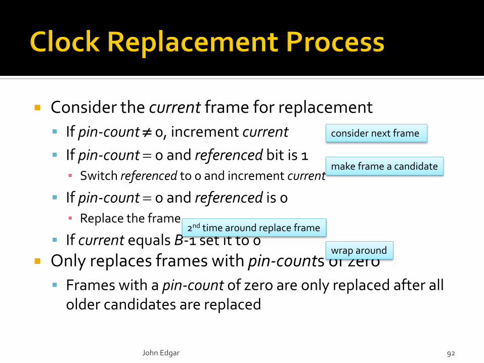
Consider the current frame for replacement
If pin-count 0, increment current
If pin-count 0 and referenced bit is 1▪ Switch referenced to 0 and increment current
If pin-count 0 and referenced is 0▪ Replace the frame
If current equals B-1 set it to 0
Only replaces frames with pin-counts of zero
Frames with a pin-count of zero are only replaced after all older candidates are replaced
John Edgar 92
consider next frame
make frame a candidate
2nd time around replace frame
wrap around
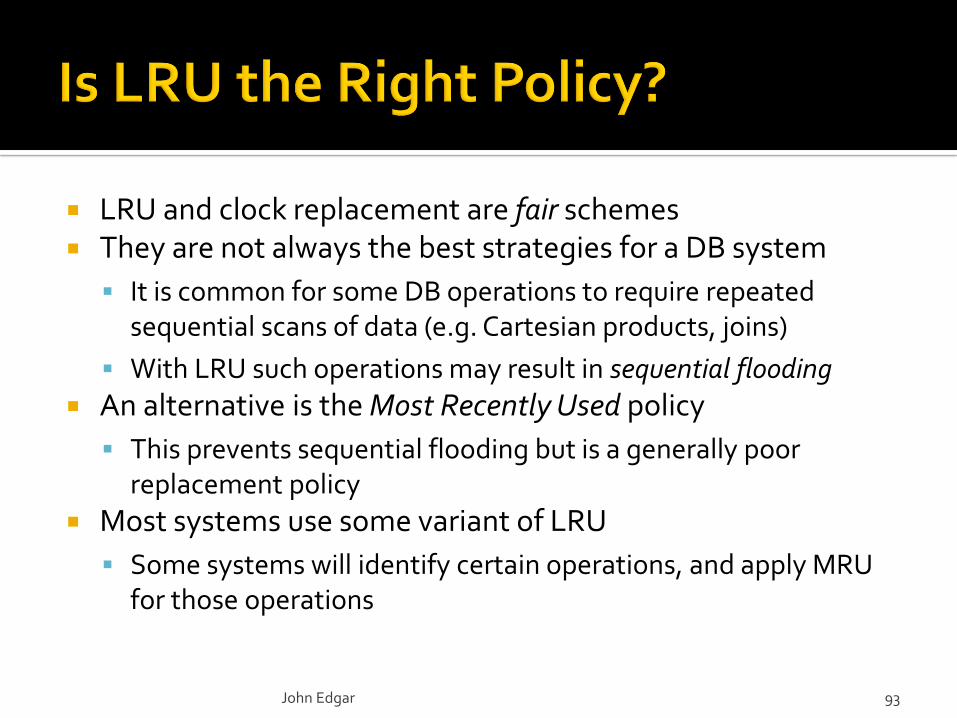
LRU and clock replacement are fair schemes They are not always the best strategies for a DB system
It is common for some DB operations to require repeated sequential scans of data (e.g. Cartesian products, joins)
With LRU such operations may result in sequential flooding
An alternative is the Most Recently Used policy
This prevents sequential flooding but is a generally poor replacement policy
Most systems use some variant of LRU
Some systems will identify certain operations, and apply MRU for those operations
John Edgar 93
p1p1 p2p1 p2 p3 p4 p5 p6 p7 p8 p9
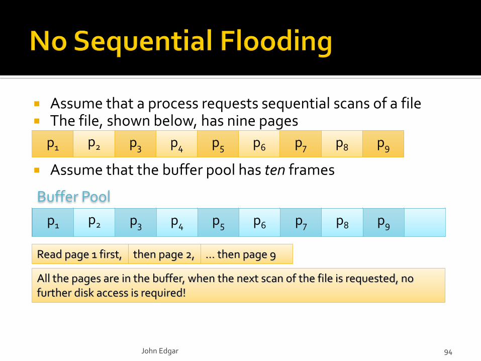
Assume that a process requests sequential scans of a file The file, shown below, has nine pages
Assume that the buffer pool has ten frames
p1 p2 p3 p4 p5 p6 p7 p8 p9
Read page 1 first,
All the pages are in the buffer, when the next scan of the file is requested, no further disk access is required!
Buffer Pool
then page 2, … then page 9
John Edgar 94
p1p1 p2p1 p2 p3 p4 p5 p6 p7 p8 p9 p10
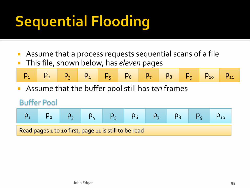
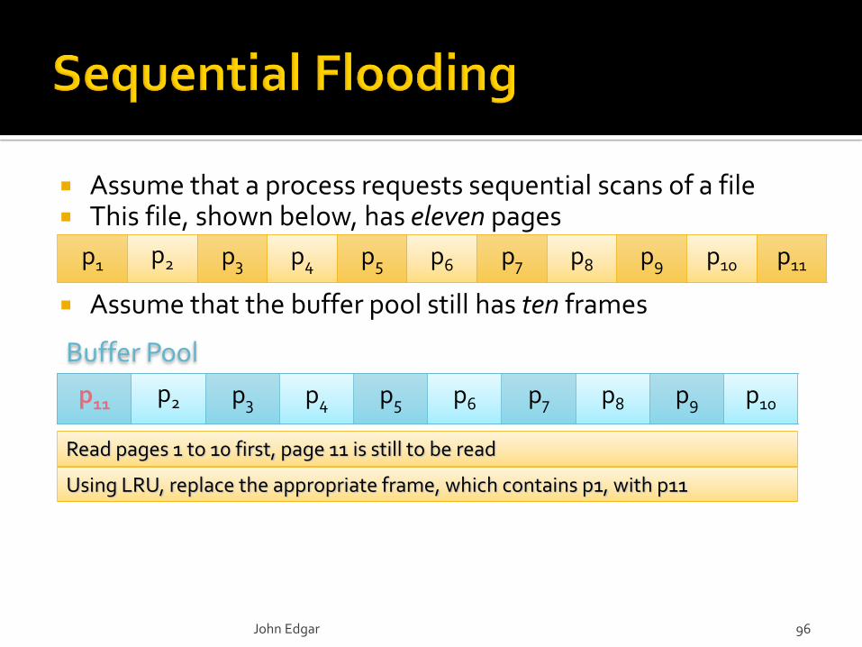
Read pages 1 to 10 first, page 11 is still to be read
Assume that a process requests sequential scans of a file This file, shown below, has eleven pages
Assume that the buffer pool still has ten frames
p1 p2 p3 p4 p5 p6 p7 p8 p9 p10 p11
Buffer Pool
John Edgar 95
p1 p2 p3 p4 p5 p6 p7 p8 p9 p10p11 p2 p3 p4 p5 p6 p7 p8 p9 p10
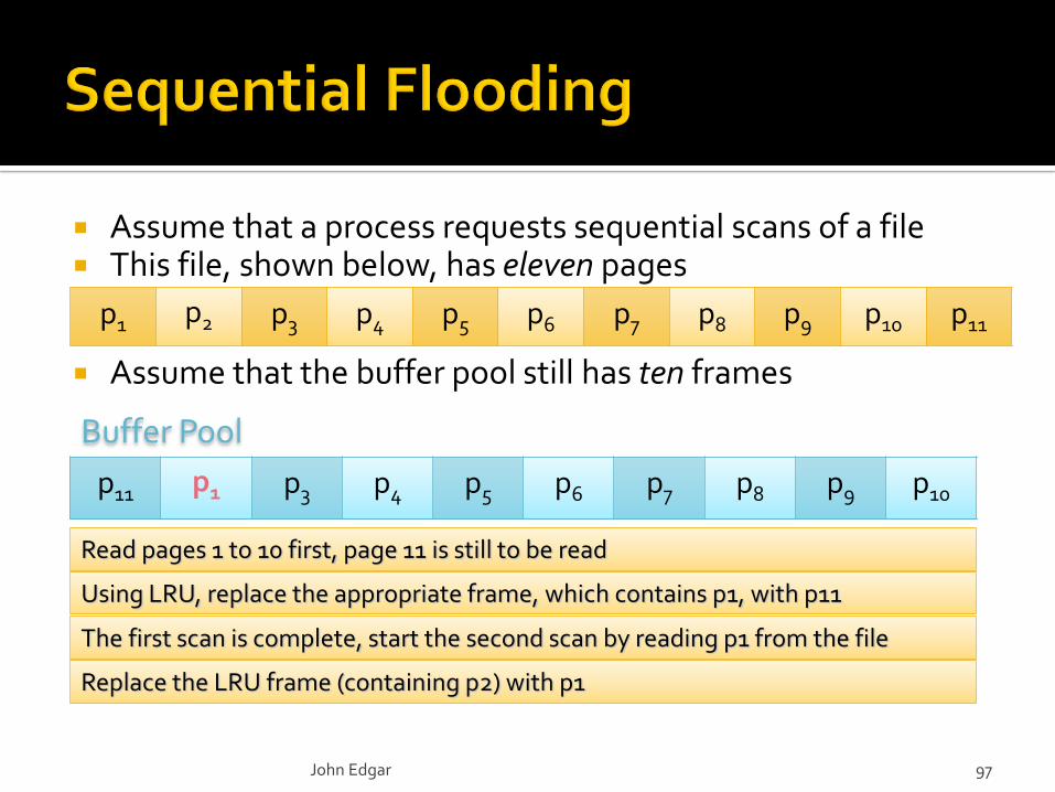
Read pages 1 to 10 first, page 11 is still to be read
Buffer Pool
Using LRU, replace the appropriate frame, which contains p1, with p11
John Edgar 96
Assume that a process requests sequential scans of a file This file, shown below, has eleven pages
Assume that the buffer pool still has ten frames
p1 p2 p3 p4 p5 p6 p7 p8 p9 p10 p11
p11 p2 p3 p4 p5 p6 p7 p8 p9 p10p11 p1 p3 p4 p5 p6 p7 p8 p9 p10
Read pages 1 to 10 first, page 11 is still to be read
Buffer Pool
Using LRU, replace the appropriate frame, which contains p1, with p11
John Edgar 97
Assume that a process requests sequential scans of a file This file, shown below, has eleven pages
Assume that the buffer pool still has ten frames
p1 p2 p3 p4 p5 p6 p7 p8 p9 p10 p11
The first scan is complete, start the second scan by reading p1 from the file
Replace the LRU frame (containing p2) with p1
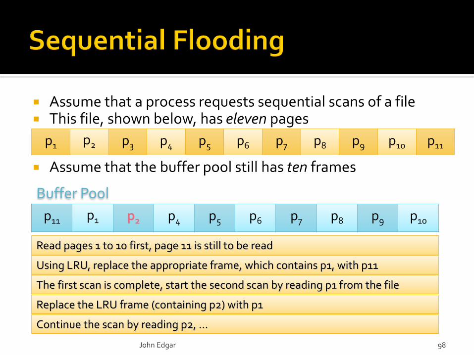
p11 p1 p3 p4 p5 p6 p7 p8 p9 p10p11 p1 p2 p4 p5 p6 p7 p8 p9 p10
Read pages 1 to 10 first, page 11 is still to be read
Buffer Pool
Using LRU, replace the appropriate frame, which contains p1, with p11
The first scan is complete, start the second scan by reading p1 from the file
Replace the LRU frame (containing p2) with p1
Continue the scan by reading p2, …
John Edgar 98
Assume that a process requests sequential scans of a file This file, shown below, has eleven pages
Assume that the buffer pool still has ten frames
p1 p2 p3 p4 p5 p6 p7 p8 p9 p10 p11
p11 p1 p2 p4 p5 p6 p7 p8 p9 p10p11 p1 p2 p3 p5 p6 p7 p8 p9 p10p11 p1 p2 p3 p4 p6 p7 p8 p9 p10p11 p1 p2 p3 p4 p5 p7 p8 p9 p10p11 p1 p2 p3 p4 p5 p6 p8 p9 p10p11 p1 p2 p3 p4 p5 p6 p7 p9 p10p11 p1 p2 p3 p4 p5 p6 p7 p8 p10p11 p1 p2 p3 p4 p5 p6 p7 p8 p9p10 p1 p2 p3 p4 p5 p6 p7 p8 p9p10 p11 p2 p3 p4 p5 p6 p7 p8 p9
Buffer Pool
John Edgar 99
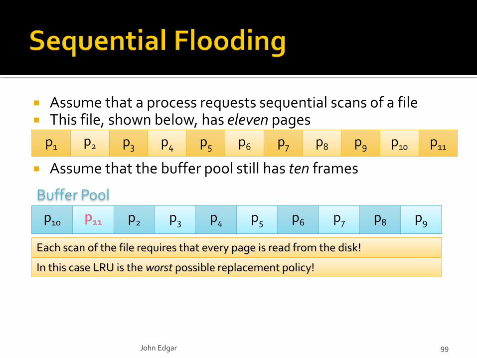
Assume that a process requests sequential scans of a file This file, shown below, has eleven pages
Assume that the buffer pool still has ten frames
p1 p2 p3 p4 p5 p6 p7 p8 p9 p10 p11
Each scan of the file requires that every page is read from the disk!
In this case LRU is the worst possible replacement policy!
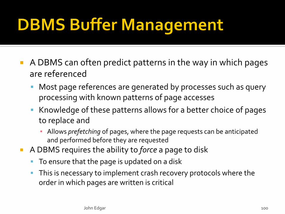
A DBMS can often predict patterns in the way in which pages are referenced
Most page references are generated by processes such as query processing with known patterns of page accesses
Knowledge of these patterns allows for a better choice of pages to replace and▪ Allows prefetching of pages, where the page requests can be anticipated
and performed before they are requested
A DBMS requires the ability to force a page to disk
To ensure that the page is updated on a disk
This is necessary to implement crash recovery protocols where the order in which pages are written is critical
John Edgar 100
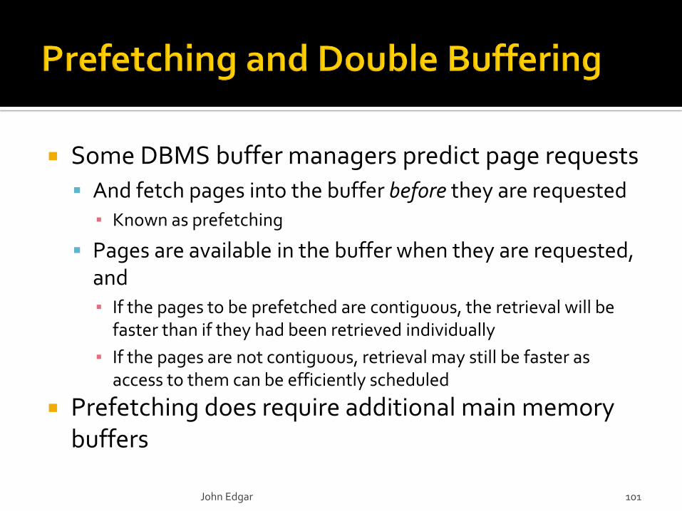
Some DBMS buffer managers predict page requests
And fetch pages into the buffer before they are requested▪ Known as prefetching
Pages are available in the buffer when they are requested, and▪ If the pages to be prefetched are contiguous, the retrieval will be
faster than if they had been retrieved individually
▪ If the pages are not contiguous, retrieval may still be faster as access to them can be efficiently scheduled
Prefetching does require additional main memory buffers
John Edgar 101
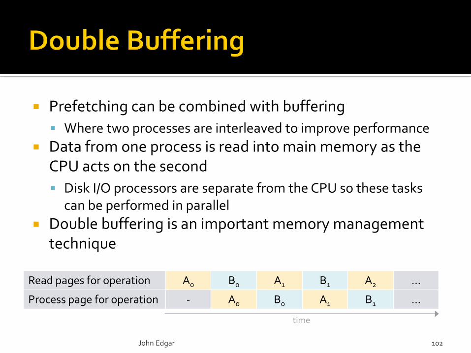
Prefetching can be combined with buffering
Where two processes are interleaved to improve performance
Data from one process is read into main memory as the CPU acts on the second
Disk I/O processors are separate from the CPU so these tasks can be performed in parallel
Double buffering is an important memory management technique
John Edgar 102
Read pages for operation A0 B0 A1 B1 A2 …
Process page for operation - A0 B0 A1 B1 …
time
Organize data by cylinders
Related data should be stored "close to" each other
Use a RAID system to improve efficiency or reliability
Multiple disks and striping improves efficiency
Mirroring or redundancy improves reliability
Schedule requests using the elevator algorithm
Reduces disk access time for random reads and writes
Most effective when there are many requests waiting
Prefetch data in large chunks and use double buffering
Speeds up access when needed blocks can be predicted but requires more main memory buffers
John Edgar 103
5.2
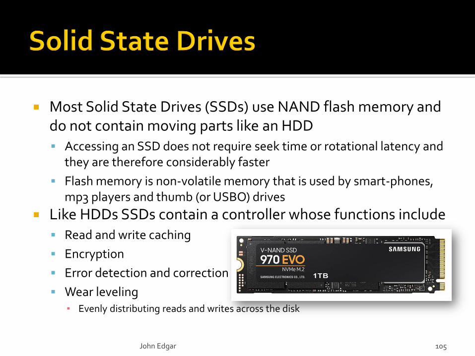
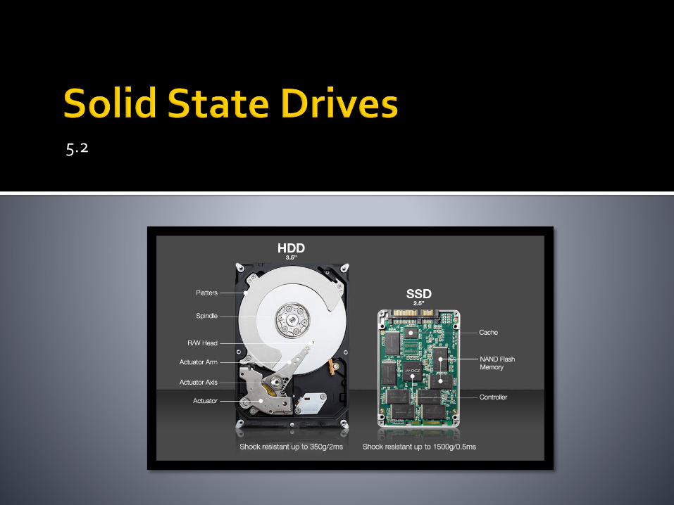
Most Solid State Drives (SSDs) use NAND flash memory and do not contain moving parts like an HDD Accessing an SSD does not require seek time or rotational latency and
they are therefore considerably faster
Flash memory is non-volatile memory that is used by smart-phones, mp3 players and thumb (or USBO) drives
Like HDDs SSDs contain a controller whose functions include Read and write caching
Encryption
Error detection and correction
Wear leveling▪ Evenly distributing reads and writes across the disk
John Edgar 105
NAND flash architecture is similar to a NAND (negated and) logic gate hence the name
Only able to read and write data one page at a time
NAND flash memory is non-volatile▪ It does not require power to retain memory
Earlier SSDs used DRAM which necessitated an internal power supply
There are different types of NAND SSD
SSD with multiple charge levels
▪ Multi-level cell (MLC), Triple Level Cell (TLC), Quad Level Cell (QLC)
Single-level cell (SLC)
John Edgar 106
Re-writing SSD data requiresfirst erasing the entire block – i.e.multiple pages
An SSD page isa few kB in size
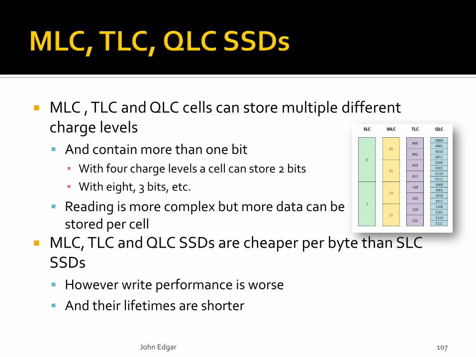
MLC , TLC and QLC cells can store multiple different charge levels
And contain more than one bit
▪ With four charge levels a cell can store 2 bits
▪ With eight, 3 bits, etc.
Reading is more complex but more data can bestored per cell
MLC, TLC and QLC SSDs are cheaper per byte than SLC SSDs
However write performance is worse
And their lifetimes are shorter
John Edgar 107
SLC cells can only store a single charge level
They are therefore on or off, and can contain only one bit
SLC drives are less complex
More reliable with a lower error rate
Faster since it is easier to read or write a single charge value
But SLC drives are more expensive
And were typically used for enterprise rather than home use
John Edgar 108
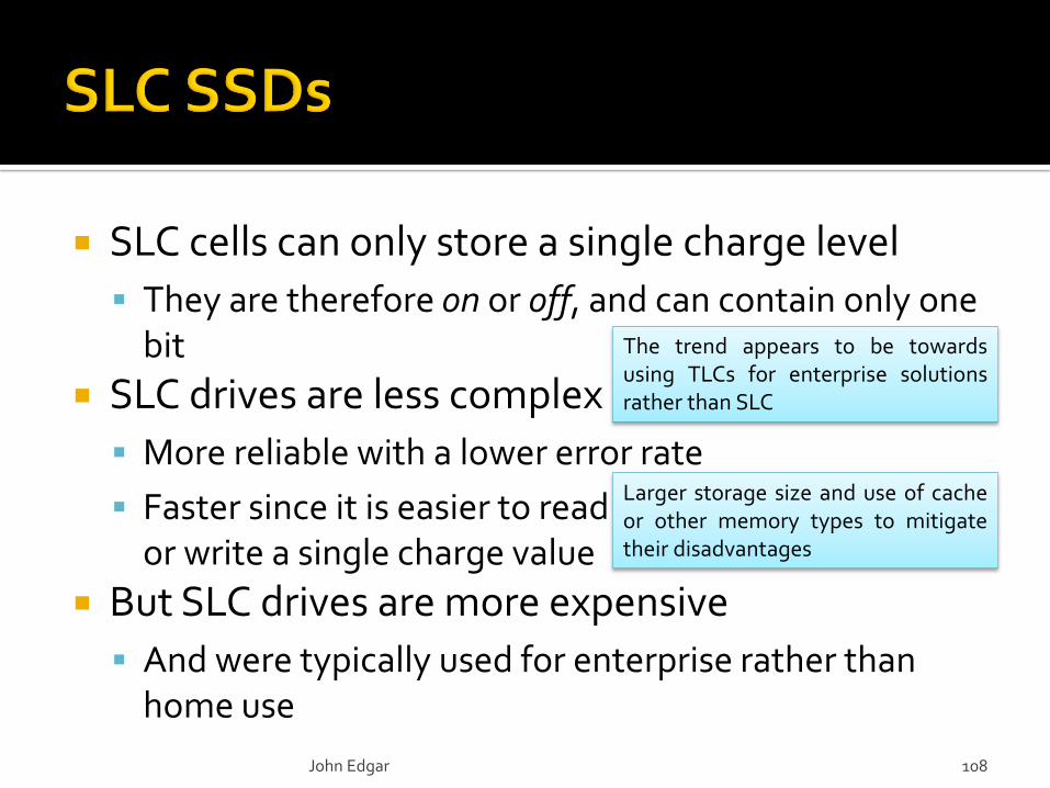
The trend appears to be towardsusing TLCs for enterprise solutionsrather than SLC
Larger storage size and use of cacheor other memory types to mitigatetheir disadvantages

An EFD is an Enterprise Flash Drive
The term was introduced by EMS Corporation
EFDs are designed for applications requiring high performance
Reliability
Energy efficiency
Consistent performance
There is no standard for what defines an EFD
So SSD manufacturers can claim that their high performing products are EFDs
▪ Without meeting any particular requirements
John Edgar 109
SSD technology continues to evolve
Consumer drives are decreasing in price per byte
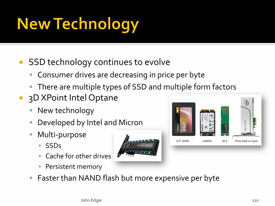
There are multiple types of SSD and multiple form factors
3D XPoint Intel Optane
New technology
Developed by Intel and Micron
Multi-purpose
▪ SSDs
▪ Cache for other drives
▪ Persistent memory
Faster than NAND flash but more expensive per byte
John Edgar 110
SSD access is entirely electronic and so no seek time
or rotational delay is incurred
Both reads and writes are faster than HDDs
However flash memory must be erased before it is written,
and entire blocks must be erased
▪ Referred to as write amplification
The performance increase over HDDs is greatest for
random reads
SSDs are considerably more durable than HDDs
Primarily due to the lack of moving parts
John Edgar 111
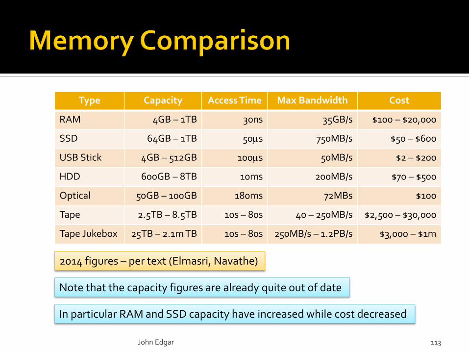
John Edgar 113
2014 figures – per text (Elmasri, Navathe)
Type Capacity Access Time Max Bandwidth Cost
RAM 4GB – 1TB 30ns 35GB/s $100 – $20,000
SSD 64GB – 1TB 50s 750MB/s $50 – $600
USB Stick 4GB – 512GB 100s 50MB/s $2 – $200
HDD 600GB – 8TB 10ms 200MB/s $70 – $500
Optical 50GB – 100GB 180ms 72MBs $100
Tape 2.5TB – 8.5TB 10s – 80s 40 – 250MB/s $2,500 – $30,000
Tape Jukebox 25TB – 2.1m TB 10s – 80s 250MB/s – 1.2PB/s $3,000 – $1m
Note that the capacity figures are already quite out of date
In particular RAM and SSD capacity have increased while cost decreased
read-modify-write cycle
no read-modify-write cycle
key
Most writes require an initial read of a disk block
Even blind writes
Consider inserting a new record into a disk block
Which contains existing records
The block must be read first
To preserve the existing data
Referred to as the read-modify-write cycle
John Edgar 114
disk
main memory
new record
existing records
disk
main memory
disk
main memory
read-modify-write cycle
no read-modify-write cycle
key
Most writes require an initial read of a disk block
Even blind writes
Consider inserting a new record into a disk block
Which contains existing records
The block must be read first
To preserve the existing data
Referred to as the read-modify-write cycle
John Edgar 115
disk
main memory
new record
existing records
disk
main memory
disk
main memory
existing data overwritten
read write
write