Embed Size (px)
DESCRIPTION
CMS Module Testing Issues. Perspective from a large scale production project Anthony Affolder (for the UCSB module testing group). Talk Overview. Review current CMS testing procedures Assorted observations from limited testing experience on CMS components - PowerPoint PPT Presentation
Citation preview
PMG Jan. 24 2002 CMS Module Testing Issues-Anthony Affolder Slide 1
CMS Module Testing Issues
Perspective from a large
scale production project
Anthony Affolder
(for the UCSB module testing group)
PMG Jan. 24 2002 CMS Module Testing Issues-Anthony Affolder Slide 2
Talk Overview• Review current CMS testing procedures • Assorted observations from limited testing
experience on CMS components• Outline UCSB module testing program
Personnel, equipment, and infrastructure
PMG Jan. 24 2002 CMS Module Testing Issues-Anthony Affolder Slide 3
CMS Testing Overview• Review current CMS testing procedures
Ensure understanding of testing prior to arrival at FNAL/UCSB– Reproduction of hybrid tests on arrival
Make sure any systematic failures in production techniques/materials found as early as possible
– M800 pre-production first chance to produce large quantities (>20) of single type of modules
– Need to be able to track time development of faults
• Answer open questions before full scale production Need of burn-in of hybrid/optical systems components Finalization of production procedure Finalization of testing procedure
– Both fault finding and module qualification
PMG Jan. 24 2002 CMS Module Testing Issues-Anthony Affolder Slide 4
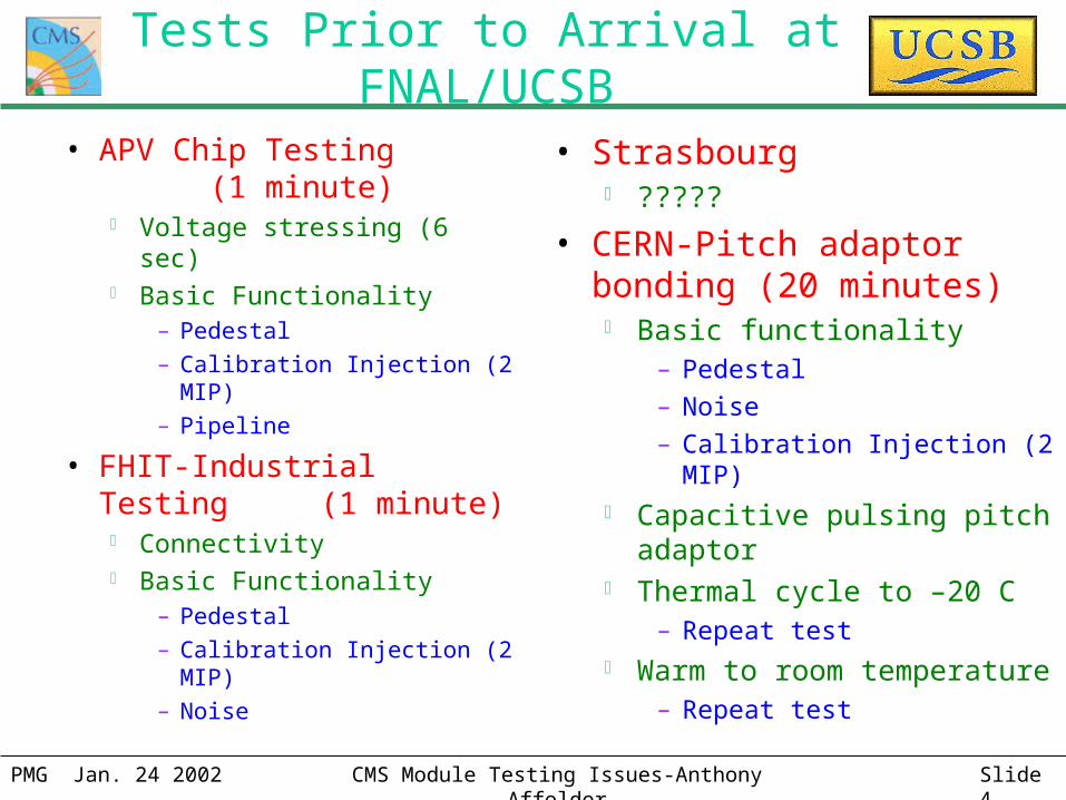
Tests Prior to Arrival at FNAL/UCSB
• APV Chip Testing (1 minute) Voltage stressing (6 sec) Basic Functionality
– Pedestal
– Calibration Injection (2 MIP)
– Pipeline
• FHIT-Industrial Testing (1 minute) Connectivity Basic Functionality
– Pedestal
– Calibration Injection (2 MIP)
– Noise
• Strasbourg ?????
• CERN-Pitch adaptor bonding (20 minutes) Basic functionality
– Pedestal
– Noise
– Calibration Injection (2 MIP) Capacitive pulsing pitch adaptor Thermal cycle to –20 C
– Repeat test Warm to room temperature
– Repeat test

PMG Jan. 24 2002 CMS Module Testing Issues-Anthony Affolder Slide 5
Testing Concerns• Hybrids tested only ~1-20 minutes
Concern about infant mortality problems
• Hybrids not completely characterized Calibration circuit only tested at one injection point Pipeline pedestal/noise not thoroughly measured
• Requirements not consistent between sites Pedestal cuts changes between test stands On-chip common mode subtraction “feature” makes noise
characteristics of open/saturated channels unpredictable
• We are attending CMS tracking week to address issues Motivate requirements on fault finding/performance issues Continuation of bringing CDF/D0 production experience to
CMS
PMG Jan. 24 2002 CMS Module Testing Issues-Anthony Affolder Slide 6
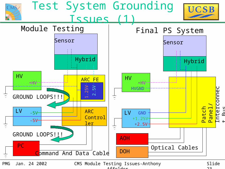
Test System Grounding Issues
• PC, DAQ/ARC, LV supplies, and HV supply share common ground Leads to less than predictable results
• Suggest that a common-mode noise standard made With on-chip common mode subtraction removed (inverter off) Allows for more uniform testing results
PMG Jan. 24 2002 CMS Module Testing Issues-Anthony Affolder Slide 7
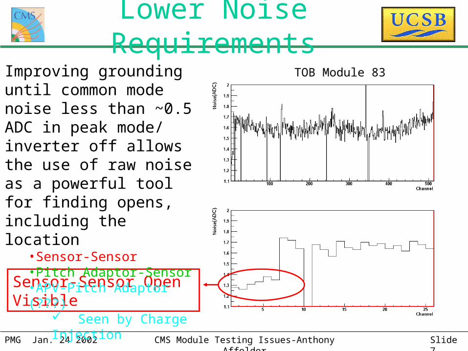
Lower Noise Requirements
Sensor-Sensor Open Visible
Improving grounding until common mode noise less than ~0.5 ADC in peak mode/ inverter off allows the use of raw noise as a powerful tool for finding opens, including the location
•Sensor-Sensor•Pitch Adaptor-Sensor•APV-Pitch Adaptor (???)
Seen by Charge Injection
TOB Module 83

PMG Jan. 24 2002 CMS Module Testing Issues-Anthony Affolder Slide 8
Upper Noise Requirements
• High noise only affects signal efficiency (clustering)
• Use physics (radioactive sources/collision data) to determine cut value Expect values to be different
for different systems
SVX
PMG Jan. 24 2002 CMS Module Testing Issues-Anthony Affolder Slide 9
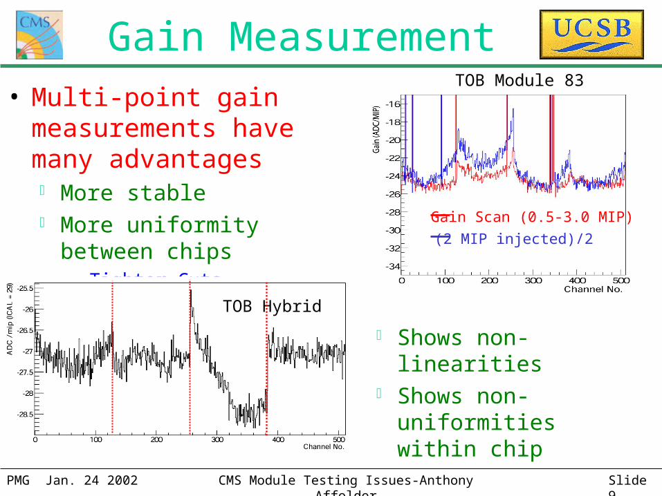
Gain Measurement• Multi-point gain measurements
have many advantages More stable More uniformity between chips
– Tighter Cuts
Shows non-linearities Shows non-uniformities
within chip
Gain Scan (0.5-3.0 MIP)
(2 MIP injected)/2
TOB Module 83
TOB Hybrid

PMG Jan. 24 2002 CMS Module Testing Issues-Anthony Affolder Slide 10
Noise Chip Edge Wings
Increase in noise at chip edges But only in a few pipeline cells pipeline scan=latency scan
Deadtimeless effect!! Fairly easy to reduce/avoid
PMG Jan. 24 2002 CMS Module Testing Issues-Anthony Affolder Slide 11
UCSB Short-term Testing Plan
• Characterize hybrid (+PA) on arrival Basic functionality, gain scan, and deep test (ARC)
• Re-characterize module on completion of construction Basic functionality, gain scan, deep test, and IV curves
(ARC)
• Vienna cold box test fraction of modules (DAQ) Acts as ~24 hour module burn-in
– Identifies mechanical/bond/electrical weaknesses prior to production of large number of modules
– Reduces reworking of rod/retrofitting of modules
• Rod assembly/characterization/burn-in (when parts and test setups available)
PMG Jan. 24 2002 CMS Module Testing Issues-Anthony Affolder Slide 12
Testing personnel at UCSB• Professors
Joe Incandela Claudio Campagnari David Stuart
• Post-docs Anthony Affolder Patrick Gartung (UC-Riverside)
• Graduate Students Steve Levy Shawn Stromburg +1-2 starting this summer
• Electrical Engineering Support Sam Burke
• ESE Master Student Anuroop Gupta
(Database/programming)
• + Assorted Undergraduates and Techs (during full production)
PMG Jan. 24 2002 CMS Module Testing Issues-Anthony Affolder Slide 13
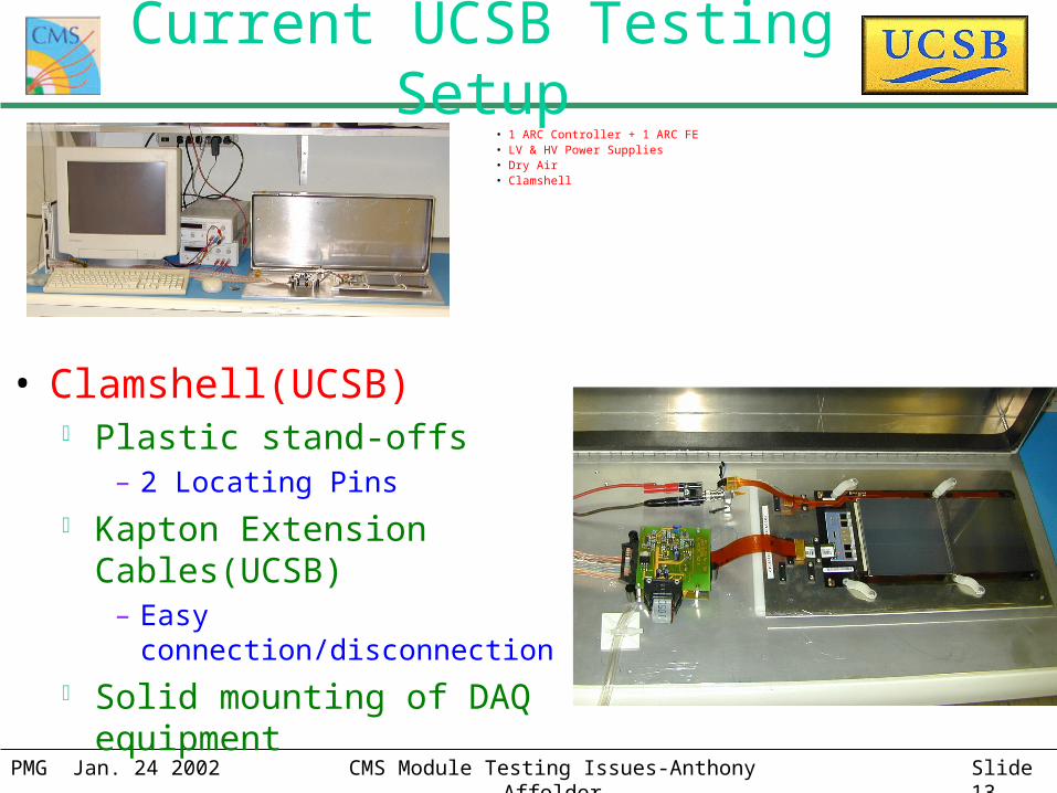
Current UCSB Testing Setup
• Clamshell(UCSB) Plastic stand-offs
– 2 Locating Pins
Kapton Extension Cables(UCSB)
– Easy connection/disconnection
Solid mounting of DAQ equipment
• 1 ARC Controller + 1 ARC FE• LV & HV Power Supplies• Dry Air• Clamshell
PMG Jan. 24 2002 CMS Module Testing Issues-Anthony Affolder Slide 14
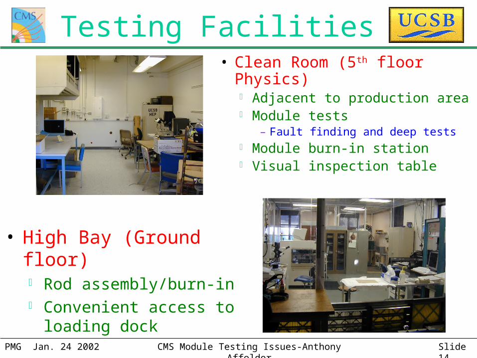
Testing Facilities
• High Bay (Ground floor) Rod assembly/burn-in Convenient access to loading
dock
• Clean Room (5th floor Physics) Adjacent to production area Module tests
– Fault finding and deep tests Module burn-in station Visual inspection table
PMG Jan. 24 2002 CMS Module Testing Issues-Anthony Affolder Slide 15
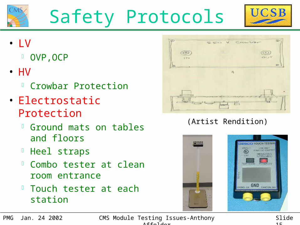
Safety Protocols• LV
OVP,OCP
• HV Crowbar Protection
• Electrostatic Protection Ground mats on tables and
floors Heel straps Combo tester at clean room
entrance Touch tester at each station
(Artist Rendition)
PMG Jan. 24 2002 CMS Module Testing Issues-Anthony Affolder Slide 16
Testing Conclusions• Slight modification of testing program would lead to
more uniform and consistent fault finding between different sites/systems Reduce rework performed on completed rods
• Location of opens can be identified by combination of noise and internal calibration measurements Useful for rod burn-in fault finding
• Increase in noise at chip edges likely deadtimeless effect We are willing to study more thoroughly
• We have the manpower and the experience necessary to aid in development of the testing program while performing module quality assurance measurements
PMG Jan. 24 2002 CMS Module Testing Issues-Anthony Affolder Slide 17
Backup Slides• EVERYTHING AFTER THIS IS BACKUP
SLIDES
PMG Jan. 24 2002 CMS Module Testing Issues-Anthony Affolder Slide 18
Possible Rod Burn-in Issues • LED systems may be necessary for discovery of
“high current” pinholes and location of opens In current rod burn-in plan, no LED systems available Would necessitate new techniques to locate “high
current” pinholes and opens– New sensor qualification tests, backplane pulsing, lower
common mode noise, etc.
• Burn-in at module stage provides important information on this issue LED tests still available Until rod components arrive this is not an issue

PMG Jan. 24 2002 CMS Module Testing Issues-Anthony Affolder Slide 19
Example of DAQ/ARC Differences
PMG Jan. 24 2002 CMS Module Testing Issues-Anthony Affolder Slide 20
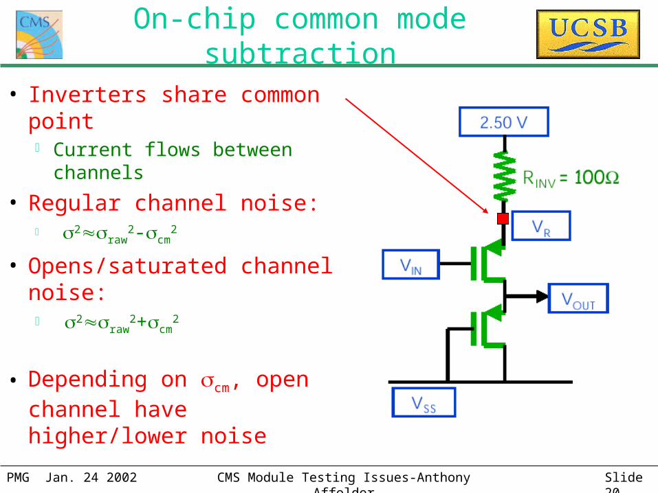
On-chip common mode subtraction
• Inverters share common point Current flows between channels
• Regular channel noise: 2raw
2-cm2
• Opens/saturated channel noise: 2raw
2+cm2
• Depending on cm, open channel have higher/lower noise
PMG Jan. 24 2002 CMS Module Testing Issues-Anthony Affolder Slide 21
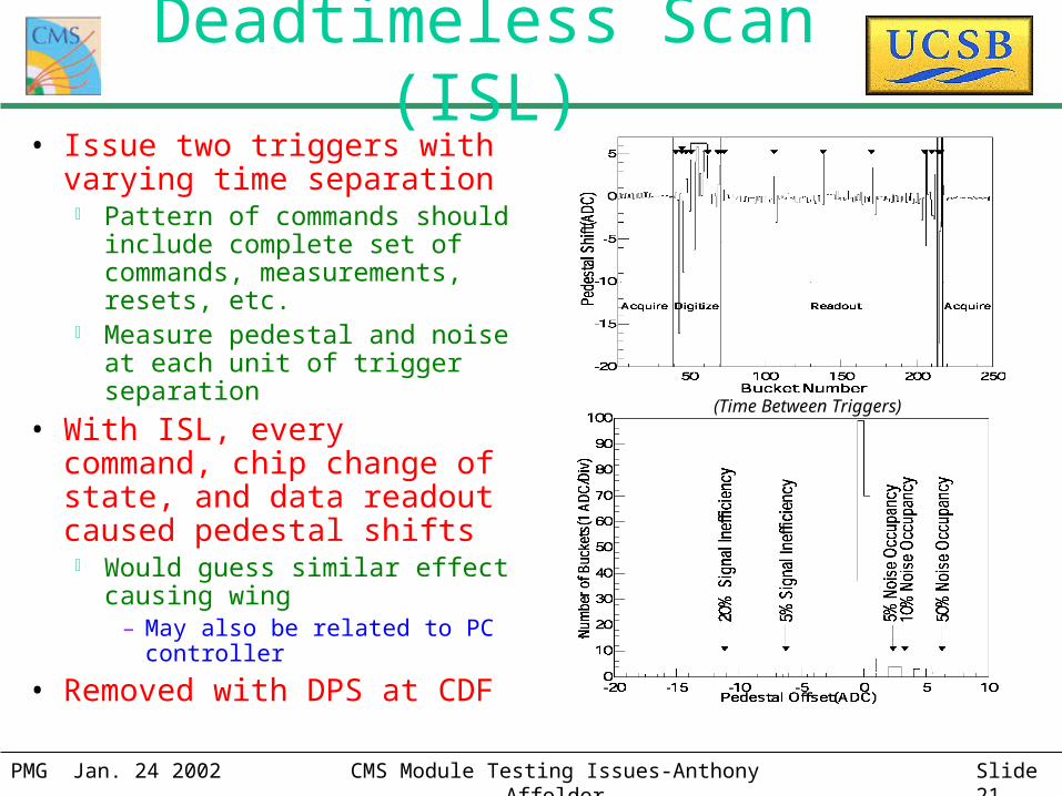
Deadtimeless Scan (ISL)• Issue two triggers with varying
time separation Pattern of commands should
include complete set of commands, measurements, resets, etc.
Measure pedestal and noise at each unit of trigger separation
• With ISL, every command, chip change of state, and data readout caused pedestal shifts Would guess similar effect
causing wing– May also be related to PC
controller
• Removed with DPS at CDF
(Time Between Triggers)
PMG Jan. 24 2002 CMS Module Testing Issues-Anthony Affolder Slide 22
Calibration Injection Test• Enhance pulse shape information with gain measurement
Measure pulse heights at 6-13 calibration injection setting between 0-3 MIPs using internal calibration and fit
Require gain between Glow and Ghigh
– Gain uniformity specification???
Require 2<2cut (2 based on noise measurement and knowledge
of calibration circuit)– Finds non-linear charge response and gain non-uniformities within
chip
• Relatively simple to include in ARC software
• Only moderately increases testing time
• Calibration is fairly sensitive to environment/grounding
PMG Jan. 24 2002 CMS Module Testing Issues-Anthony Affolder Slide 23
Test System Grounding Issues (1)Module Testing Final PS System
PC
LV -5V
-5V
ARC Controller
HV+HV
Sensor
Hybrid
ARC FE
2.5V
1.25
V
GROUND LOOPS!!!
GROUND LOOPS!!!
LV
HV+HV
Sensor
Hybrid
HVGND
GND+1.25V+2.5V
DOH
AOH
Command And Data CableOptical Cables
Patc
h Pa
nel/
Inte
rcon
nect
Bus
PMG Jan. 24 2002 CMS Module Testing Issues-Anthony Affolder Slide 24
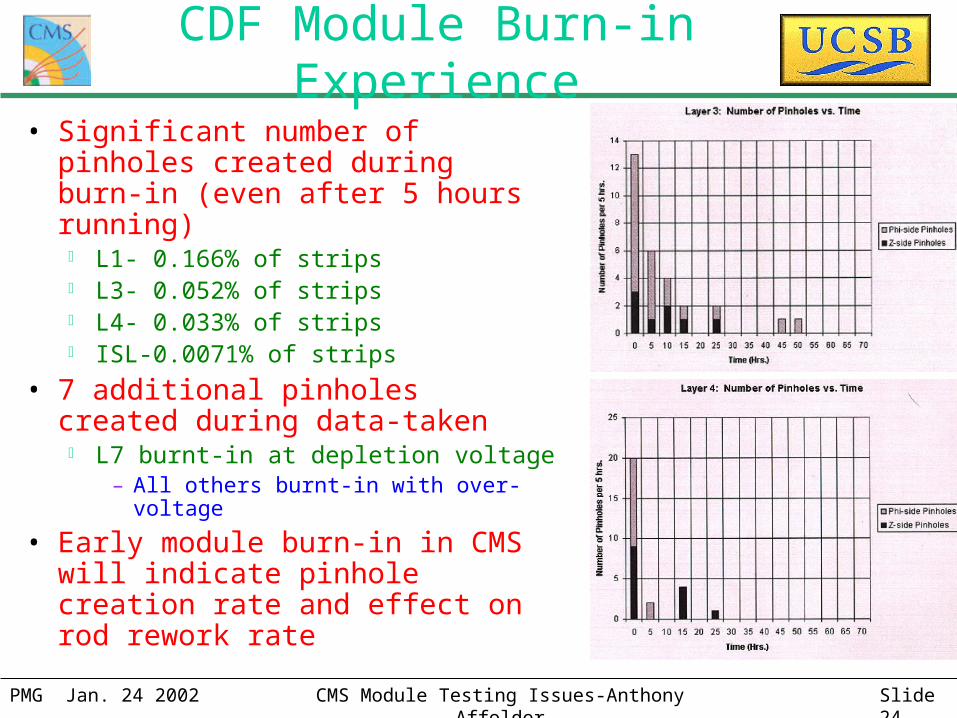
CDF Module Burn-in Experience
• Significant number of pinholes created during burn-in (even after 5 hours running) L1- 0.166% of strips L3- 0.052% of strips L4- 0.033% of strips ISL-0.0071% of strips
• 7 additional pinholes created during data-taken L7 burnt-in at depletion voltage
– All others burnt-in with over-voltage
• Early module burn-in in CMS will indicate pinhole creation rate and effect on rod rework rate
PMG Jan. 24 2002 CMS Module Testing Issues-Anthony Affolder Slide 25
Noise Measurements• Lower noise requirements optimized to detect faults in production
Very loose low noise requirement at hybrid level– Noise only changes from ~0.6~0.4 for completely dead pre-amplifier
– 20% requirement will fail good channels Hybrid at UCSB tests better with shaper current set to zero
Tighter low noise requirements at module/rod level– Can identify open types/location
Sensor-Sensor:~1.2 ADC
PA-Sensor: ~0.7 ADC
Chip-PA:~0.5 ADC
• Upper Noise requirement set by effect on signal efficiency Noise sets channel’s thresholds in clustering Effect is module type dependent
– Larger signal and wide pitch minimizes effect on noise on TOB Determine by source/cosmic testing
PMG Jan. 24 2002 CMS Module Testing Issues-Anthony Affolder Slide 26
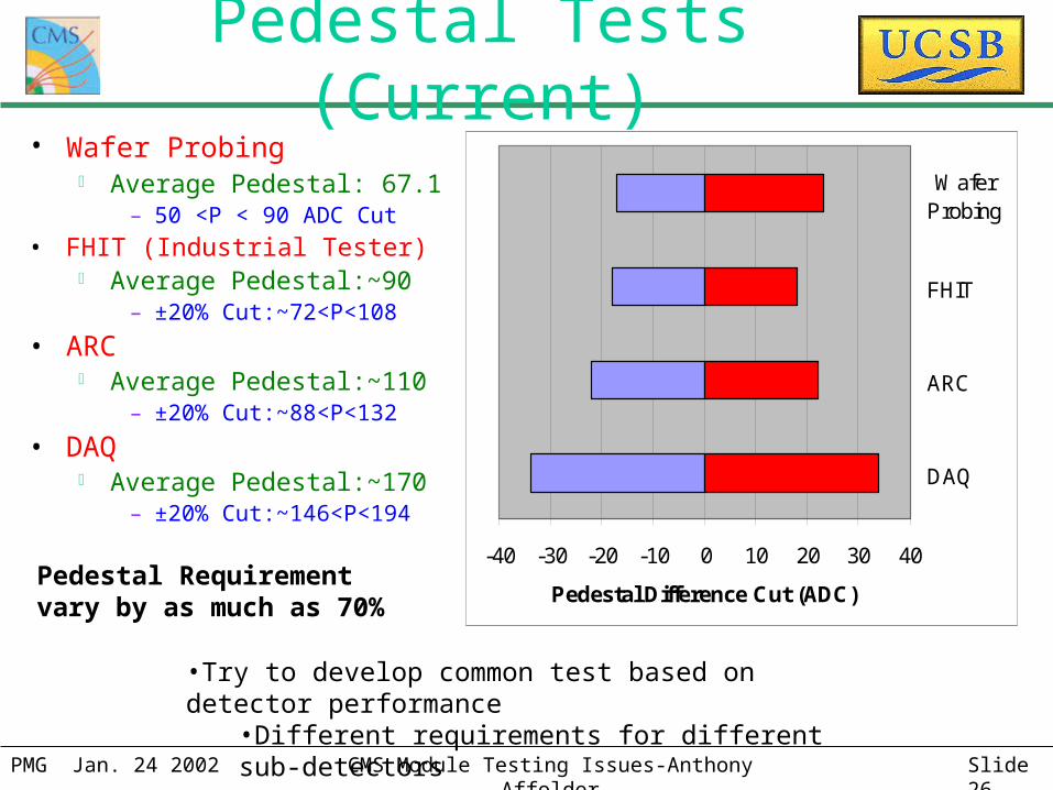
Pedestal Tests (Current)• Wafer Probing
Average Pedestal: 67.1– 50 <P < 90 ADC Cut
• FHIT (Industrial Tester) Average Pedestal:~90
– ±20% Cut:~72<P<108
• ARC Average Pedestal:~110
– ±20% Cut:~88<P<132
• DAQ Average Pedestal:~170
– ±20% Cut:~146<P<194-40 -30 -20 -10 0 10 20 30 40
DAQ
ARC
FHIT
WaferProbing
Pedestal Difference Cut (ADC)Pedestal Requirement vary by as much as 70%
•Try to develop common test based on detector performance•Different requirements for different sub-detectors
PMG Jan. 24 2002 CMS Module Testing Issues-Anthony Affolder Slide 27
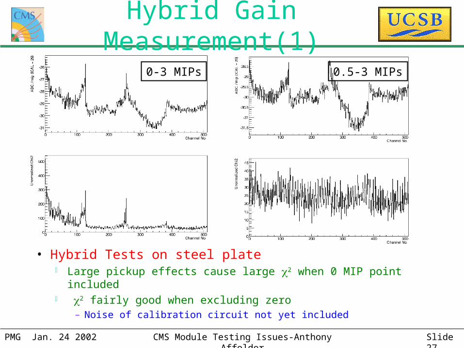
Hybrid Gain Measurement(1)
• Hybrid Tests on steel plate Large pickup effects cause large 2 when 0 MIP point included 2 fairly good when excluding zero
– Noise of calibration circuit not yet included
0-3 MIPs 0.5-3 MIPs
PMG Jan. 24 2002 CMS Module Testing Issues-Anthony Affolder Slide 28
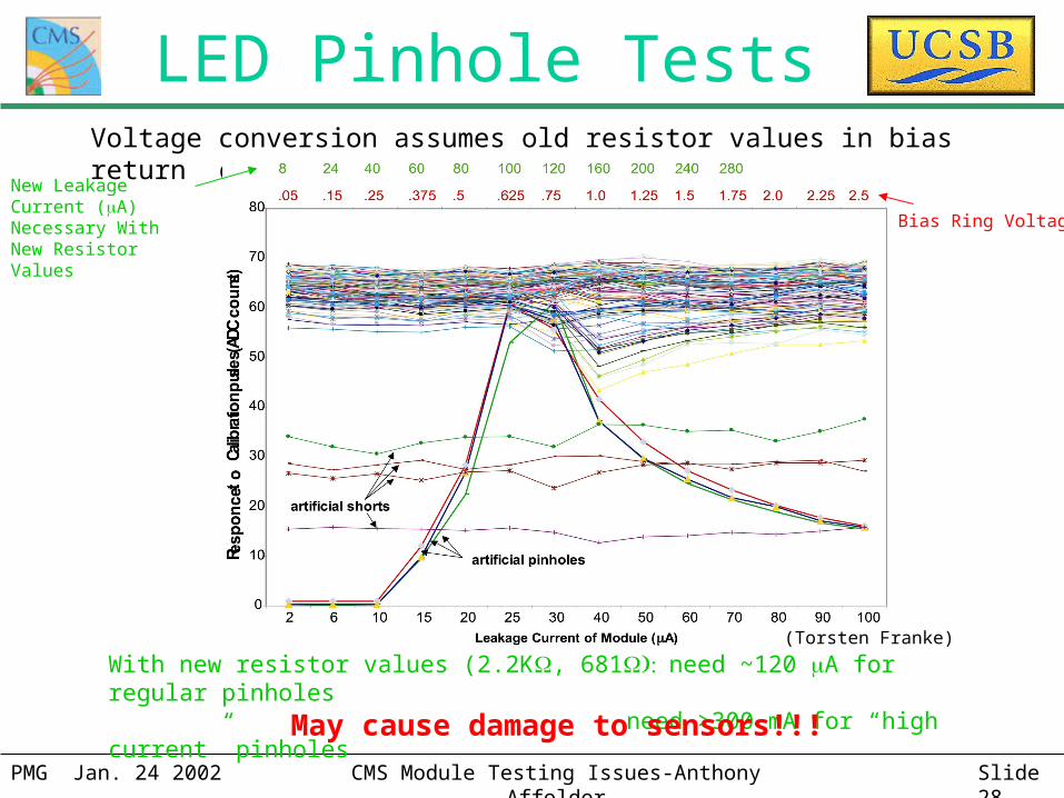
Bias Ring Voltage
Voltage conversion assumes old resistor values in bias return circuit (22K,100
With new resistor values (2.2K, 681need ~120 A for regular pinholes need >300 mA for “high current” pinholes
New Leakage Current (A) Necessary With New Resistor Values
LED Pinhole Tests
May cause damage to sensors!!!
(Torsten Franke)
PMG Jan. 24 2002 CMS Module Testing Issues-Anthony Affolder Slide 29
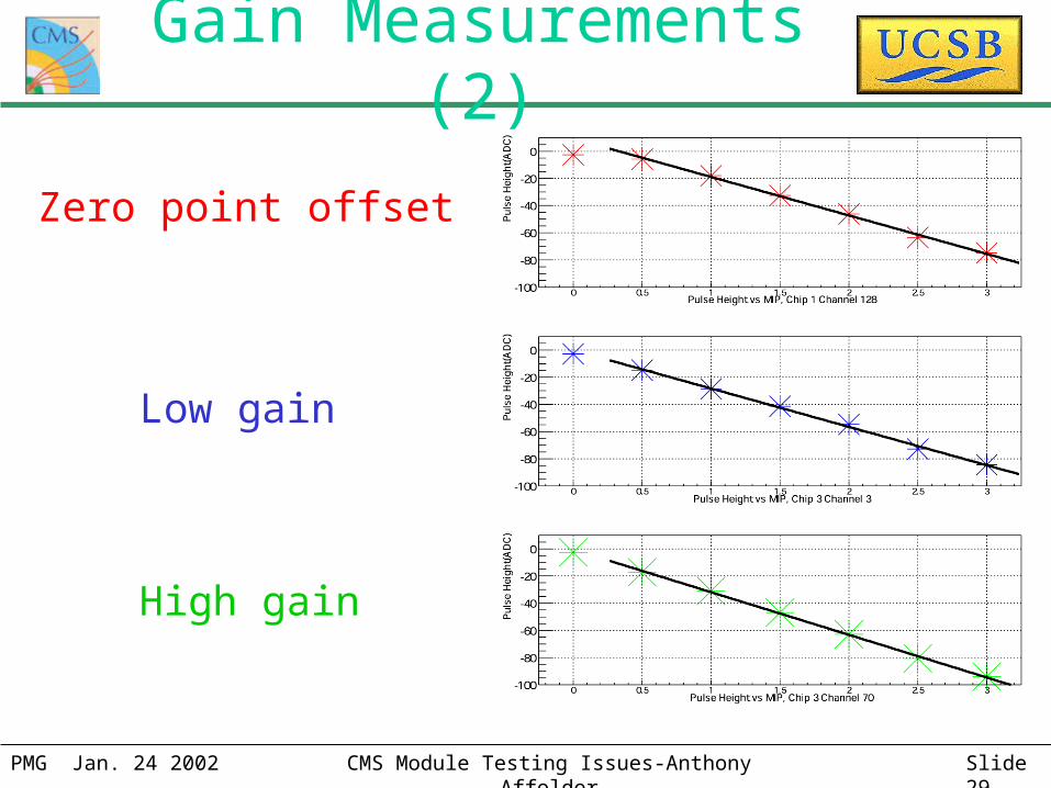
Gain Measurements (2)
Zero point offset
Low gain
High gain
PMG Jan. 24 2002 CMS Module Testing Issues-Anthony Affolder Slide 30
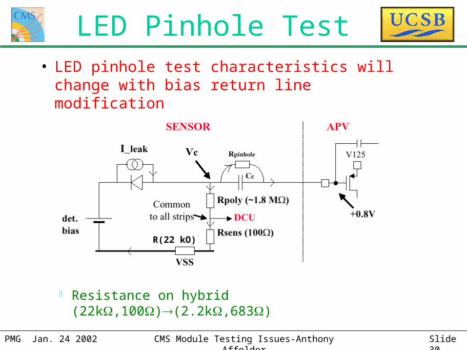
R(22 kO)
• LED pinhole test characteristics will change with bias return line modification
Resistance on hybrid (22k,100)(2.2k,683)
LED Pinhole Test
PMG Jan. 24 2002 CMS Module Testing Issues-Anthony Affolder Slide 31
Test model(1)• Add hybrid qualification prior to pitch adaptor bonding
Thorough understanding of hybrids by adding more pipeline and gain measurements
• Make requirements/calculation algorithms consistent through testing process Wafer Probing FHITStrasburg Pitch Adaptor Bonding Module
Construction Rod Construction/burn-in– Allows for the reproduction of bad channel lists
– Eases tracking of fault creation
• Motivate requirements for fault finding and on silicon tracker performance Noise Occupancy Signal Efficiency Signal Resolution

PMG Jan. 24 2002 CMS Module Testing Issues-Anthony Affolder Slide 32
Test model(2)• Improve system’s noise in order to use as powerful tool
Identification of location of opens
• Modify deep tests Suggest different bad channel cuts specific to component type tested Remove all percentage requirements (relative to average) Replace with fixed requirements
• Use cooling box as module burn-in until shown unnecessary Reduces reworking during rod assembly Adds important information about necessity of LED tests for the finding of
some pinholes and opens locations Demonstrates if hybrid burn-in necessary