Embed Size (px)
Citation preview
A product of VULCAN-HART LOUISVILLE, KY 40201-0696F25121(February 2003)
- NOTICE -This Manual is prepared for the use of trained Vulcan ServiceTechnicians and should not be used by those not properlyqualified. If you have attended a Vulcan Service School for thisproduct, you may be qualified to perform all the proceduresdescribed in this manual.
This manual is not intended to be all encompassing. If you havenot attended a Vulcan Service School for this product, you shouldread, in its entirety, the repair procedure you wish to perform todetermine if you have the necessary tools, instruments and skillsrequired to perform the procedure. Procedures for which you donot have the necessary tools, instruments and skills should beperformed by a trained Vulcan Service Technician.
Reproduction or other use of this Manual, without the expresswritten consent of Vulcan, is prohibited.
VG40 SHOWN
SERVICE MANUAL
GAS BRAISING PANS(30 & 40 GALLON)
VG30 ML-126847
VG40 ML-126848
For additional information on Vulcan-Hart Company or to locate an authorized partsand service provider in your area, visit our website at www.vulcanhart.com.

GAS BRAISING PANS
F25121 (February 2003) Page 2 of 32
TABLE OF CONTENTSGENERAL . . . . . . . . . . . . . . . . . . . . . . . . . . . . . . . . . . . . . . . . . . . . . . . . . . . . . . . . . . . . . . . . . . . . . . . . . . . . . . . . 3
Installation, Operation and Cleaning . . . . . . . . . . . . . . . . . . . . . . . . . . . . . . . . . . . . . . . . . . . . . . . . . . . . . . . . . 3Introduction . . . . . . . . . . . . . . . . . . . . . . . . . . . . . . . . . . . . . . . . . . . . . . . . . . . . . . . . . . . . . . . . . . . . . . . . . . . . 3
Control Panel . . . . . . . . . . . . . . . . . . . . . . . . . . . . . . . . . . . . . . . . . . . . . . . . . . . . . . . . . . . . . . . . . . . . . . 3Model Designations . . . . . . . . . . . . . . . . . . . . . . . . . . . . . . . . . . . . . . . . . . . . . . . . . . . . . . . . . . . . . . . . . 3
Tools . . . . . . . . . . . . . . . . . . . . . . . . . . . . . . . . . . . . . . . . . . . . . . . . . . . . . . . . . . . . . . . . . . . . . . . . . . . . . . . . . 3Specifications . . . . . . . . . . . . . . . . . . . . . . . . . . . . . . . . . . . . . . . . . . . . . . . . . . . . . . . . . . . . . . . . . . . . . . . . . . 3
REMOVAL AND REPLACEMENT OF PARTS . . . . . . . . . . . . . . . . . . . . . . . . . . . . . . . . . . . . . . . . . . . . . . . . . . . . 4Covers and Panels . . . . . . . . . . . . . . . . . . . . . . . . . . . . . . . . . . . . . . . . . . . . . . . . . . . . . . . . . . . . . . . . . . . . . . 4Power Supply Box Components . . . . . . . . . . . . . . . . . . . . . . . . . . . . . . . . . . . . . . . . . . . . . . . . . . . . . . . . . . . . 5Temperature Controller . . . . . . . . . . . . . . . . . . . . . . . . . . . . . . . . . . . . . . . . . . . . . . . . . . . . . . . . . . . . . . . . . . 5Pan Position/Down Limit Switch . . . . . . . . . . . . . . . . . . . . . . . . . . . . . . . . . . . . . . . . . . . . . . . . . . . . . . . . . . . . 6Thermocouple Probe . . . . . . . . . . . . . . . . . . . . . . . . . . . . . . . . . . . . . . . . . . . . . . . . . . . . . . . . . . . . . . . . . . . . 8DC Lift Motor . . . . . . . . . . . . . . . . . . . . . . . . . . . . . . . . . . . . . . . . . . . . . . . . . . . . . . . . . . . . . . . . . . . . . . . . . . 9Gear Reducer . . . . . . . . . . . . . . . . . . . . . . . . . . . . . . . . . . . . . . . . . . . . . . . . . . . . . . . . . . . . . . . . . . . . . . . . . 10Gas Combination Valve . . . . . . . . . . . . . . . . . . . . . . . . . . . . . . . . . . . . . . . . . . . . . . . . . . . . . . . . . . . . . . . . . 11Pilot Burner . . . . . . . . . . . . . . . . . . . . . . . . . . . . . . . . . . . . . . . . . . . . . . . . . . . . . . . . . . . . . . . . . . . . . . . . . . . 12Runner Tube . . . . . . . . . . . . . . . . . . . . . . . . . . . . . . . . . . . . . . . . . . . . . . . . . . . . . . . . . . . . . . . . . . . . . . . . . . 12Main Burners . . . . . . . . . . . . . . . . . . . . . . . . . . . . . . . . . . . . . . . . . . . . . . . . . . . . . . . . . . . . . . . . . . . . . . . . . 13Lid Springs . . . . . . . . . . . . . . . . . . . . . . . . . . . . . . . . . . . . . . . . . . . . . . . . . . . . . . . . . . . . . . . . . . . . . . . . . . . 13
SERVICE PROCEDURES AND ADJUSTMENTS . . . . . . . . . . . . . . . . . . . . . . . . . . . . . . . . . . . . . . . . . . . . . . . . . 15Temperature Controller Calibration . . . . . . . . . . . . . . . . . . . . . . . . . . . . . . . . . . . . . . . . . . . . . . . . . . . . . . . . 15Temperature Controller Test . . . . . . . . . . . . . . . . . . . . . . . . . . . . . . . . . . . . . . . . . . . . . . . . . . . . . . . . . . . . . 16Thermocouple Test . . . . . . . . . . . . . . . . . . . . . . . . . . . . . . . . . . . . . . . . . . . . . . . . . . . . . . . . . . . . . . . . . . . . 16Spark Ignition Test . . . . . . . . . . . . . . . . . . . . . . . . . . . . . . . . . . . . . . . . . . . . . . . . . . . . . . . . . . . . . . . . . . . . . 17Pilot Burner Flame Adjustment . . . . . . . . . . . . . . . . . . . . . . . . . . . . . . . . . . . . . . . . . . . . . . . . . . . . . . . . . . . . 18Flame Sense Current Test . . . . . . . . . . . . . . . . . . . . . . . . . . . . . . . . . . . . . . . . . . . . . . . . . . . . . . . . . . . . . . . 19Ignition Control Module Test . . . . . . . . . . . . . . . . . . . . . . . . . . . . . . . . . . . . . . . . . . . . . . . . . . . . . . . . . . . . . . 19Gas Manifold Pressure Adjustment . . . . . . . . . . . . . . . . . . . . . . . . . . . . . . . . . . . . . . . . . . . . . . . . . . . . . . . . 20Main Burners . . . . . . . . . . . . . . . . . . . . . . . . . . . . . . . . . . . . . . . . . . . . . . . . . . . . . . . . . . . . . . . . . . . . . . . . . 21
Inspection . . . . . . . . . . . . . . . . . . . . . . . . . . . . . . . . . . . . . . . . . . . . . . . . . . . . . . . . . . . . . . . . . . . . . . . . 21Air Shutter Adjustment . . . . . . . . . . . . . . . . . . . . . . . . . . . . . . . . . . . . . . . . . . . . . . . . . . . . . . . . . . . . . . 21
DC Motor Controller Test . . . . . . . . . . . . . . . . . . . . . . . . . . . . . . . . . . . . . . . . . . . . . . . . . . . . . . . . . . . . . . . . 22Pan Position/Down Limit Switch Adjustment . . . . . . . . . . . . . . . . . . . . . . . . . . . . . . . . . . . . . . . . . . . . . . . . . 22Lid Spring Tension Adjustment . . . . . . . . . . . . . . . . . . . . . . . . . . . . . . . . . . . . . . . . . . . . . . . . . . . . . . . . . . . . 23
ELECTRICAL OPERATION . . . . . . . . . . . . . . . . . . . . . . . . . . . . . . . . . . . . . . . . . . . . . . . . . . . . . . . . . . . . . . . . . . 25Component Function . . . . . . . . . . . . . . . . . . . . . . . . . . . . . . . . . . . . . . . . . . . . . . . . . . . . . . . . . . . . . . . . . . . 25Component Location . . . . . . . . . . . . . . . . . . . . . . . . . . . . . . . . . . . . . . . . . . . . . . . . . . . . . . . . . . . . . . . . . . . 26Ignition Control Module . . . . . . . . . . . . . . . . . . . . . . . . . . . . . . . . . . . . . . . . . . . . . . . . . . . . . . . . . . . . . . . . . . 27Sequence of Operation . . . . . . . . . . . . . . . . . . . . . . . . . . . . . . . . . . . . . . . . . . . . . . . . . . . . . . . . . . . . . . . . . . 28Schematic Diagram . . . . . . . . . . . . . . . . . . . . . . . . . . . . . . . . . . . . . . . . . . . . . . . . . . . . . . . . . . . . . . . . . . . . 30
TROUBLESHOOTING . . . . . . . . . . . . . . . . . . . . . . . . . . . . . . . . . . . . . . . . . . . . . . . . . . . . . . . . . . . . . . . . . . . . . . 31Gas Heating (Manual Lift or Motorized Lift Option) . . . . . . . . . . . . . . . . . . . . . . . . . . . . . . . . . . . . . . . . . . . . 31Motorized Lift Option Only . . . . . . . . . . . . . . . . . . . . . . . . . . . . . . . . . . . . . . . . . . . . . . . . . . . . . . . . . . . . . . . 32
CONDENSED SPARE PARTS LIST . . . . . . . . . . . . . . . . . . . . . . . . . . . . . . . . . . . . . . . . . . . . . . . . . . . . . . . . . . . 32
© VULCAN 2003

GAS BRAISING PANS
F25121 (February 2003)Page 3 of 32
GENERALINSTALLATION, OPERATION
AND CLEANINGRefer to the Installation & Operation Manual forspecific instructions.
INTRODUCTIONThe tilting braising pan (skillet) is a versatile piece ofcooking equipment. It can be used to stew, simmer,steam, sear, pan fry, grill or saute food products overan evenly distributed heating surface. Once theproduct is fully cooked, the pan can be tilted for easeof product removal.
Control Panel
Model Designations! VG30 - 30 gallon capacity
! VG40 - 40 gallons capacity
TOOLSStandard! Standard set of hand tools.
! VOM with an AC current tester and DC microamp current tester capable of measuring 0-10micro amps.
NOTE: Any quality VOM with a sensitivity of20,000 ohms per volt can be used.
! U-Tube Manometer.
! Temperature tester (thermocouple type) withsurface probe.
Special! 1 5/8" open end wrench. Used for removing lid
springs and adjusting lid spring tension.
! Field service grounding kit P/N TL- 84919.
! RTV sealant Dow Corning 732 or equivalent.Used for sealing the slot in top cover for the gascombination valve.
! Pipe thread sealant suitable for natural andpropane gases.
SPECIFICATIONS
MODEL
INPUTBTU/HR
MANIFOLDPRESSURE
(INCHES W.C.)
LINE PRESSURE(INCHES W.C.)
AMPS (MAX)@ 120V/60HZNATURAL PROPANE
NAT. PROP. NAT. PROP. RECOMMEND MIN RECOMMEND MIN MAX
VG30 90,000 90,000 3.7 10.0 7.0 5.0 11.0 11.0 14.03.0
VG40 120,000 120,000 3.7 10.0 7.0 5.0 11.0 11.0 14.0

GAS BRAISING PANS - REMOVAL AND REPLACEMENT OF PARTS
F25121 (February 2003) Page 4 of 32
REMOVAL AND REPLACEMENT OF PARTSCOVERS AND PANELS
WARNING: DISCONNECT THEELECTRICAL POWER TO THEMACHINE AND FOLLOW LOCKOUT /TAGOUT PROCEDURES.
Front, Rear & Side Panels1. Lift up on the bottom edge of panel until it clears
the catch.
2. Tilt outwards and allow the panel to drop down.
3. Reverse procedure to install.
Control Panel1. Remove front panel.
2. Disconnect conduit from control box.
3. Remove manual lift crank handle (if installed).
4. Remove bolts securing control panel to braisingpan frame. Bolts are recessed in the framechannel.
5. Tilt bottom of control panel outwards and pulldown.
NOTE: The control panel should be supported toremove lead wire strain.
6. Remove control box from control panel.
7. Disconnect lead wires from control switch.

GAS BRAISING PANS - REMOVAL AND REPLACEMENT OF PARTS
F25121 (February 2003)Page 5 of 32
8. Pull temperature dial from potentiometer shaftand remove mounting nut.
9. Control panel is removed.
10. To install.
A. Align tab on potentiometer with positioningbracket on panel.
B. Install mounting nut and tighten.
C. Adjust stop nut on potentiometer body (asnecessary) to ensure a water tight seal onmounting nut.
D. Attach temperature dial.
11. Reverse procedure from step 6 to complete theinstallation.
12. Check calibration as outlined underTEMPERATURE CONTROLLERCALIBRATION.
POWER SUPPLY BOXCOMPONENTS
WARNING: DISCONNECT THEELECTRICAL POWER TO THEMACHINE AND FOLLOW LOCKOUT /TAGOUT PROCEDURES.
CAUTION: Certain components in this systemare subject to damage by electrostatic dischargeduring field repairs. A field service grounding kitis available to prevent damage. The field servicegrounding kit must be used anytime a controlboard is handled.
1. Remove front panel as outlined under COVERS AND PANELS.
2. Remove power supply box cover.
3. Remove the component being replaced.
4. Reverse procedure to install the replacementcomponent then check for proper operation.
TEMPERATURE CONTROLLER
WARNING: DISCONNECT THEELECTRICAL POWER TO THEMACHINE AND FOLLOW LOCKOUT /TAGOUT PROCEDURES.
1. Remove control box from the control panel asoutlined under COVERS AND PANELS.
2. Disconnect lead wires from temperaturecontroller.
3. Remove temperature controller from controlbox.

GAS BRAISING PANS - REMOVAL AND REPLACEMENT OF PARTS
F25121 (February 2003) Page 6 of 32
LEFT SIDE VIEW SHOWN
4. Pull temperature dial from potentiometer shaftand remove mounting nut.
5. To install:
A. Align tab on potentiometer with positioningbracket on panel.
B. Install mounting nut and tighten.
C. Adjust stop nut on potentiometer body (asnecessary) to ensure a water tight seal onmounting nut.
D. Attach temperature dial.
6. Reverse procedure from step 3 to complete theinstallation.
7. Check calibration as outlined underTEMPERATURE CONTROLLERCALIBRATION.
PAN POSITION/DOWN LIMITSWITCH
WARNING: DISCONNECT THEELECTRICAL POWER TO THEMACHINE AND FOLLOW LOCKOUT /TAGOUT PROCEDURES.
1. Remove front and left side panels as outlinedunder COVERS AND PANELS.
2. Disconnect conduit and remove panposition/down limit switch from switch mountingbracket.
3. Remove cover from switch.
4. Disconnect lead wires and pull wires thruconduit elbow assembly.
5. Remove conduit elbow assembly from switch.

GAS BRAISING PANS - REMOVAL AND REPLACEMENT OF PARTS
F25121 (February 2003)Page 7 of 32
TOP VIEW SHOWN
SIDE VIEW SHOWN
NOTE: When installing, replace the o-ring seal(provided) inside the brass fitting and re-use conduitelbow assembly.
6. To install:
A. Position the switch with the head pointingtoward installer and gear cam pointing up.
NOTE: The plunger on the head is spring loadedand will push the head away from switch body whenthe last screw is removed.
B. Remove screws securing the head toswitch body, rotate 90° clockwise andtighten screws to secure.
C. Place switch on its side with the head tothe left and gear cam pointing up.
D. Align roller arm adaptor with the fourlocking tabs pointing up and position oneof the tabs at 0°.
NOTE: The 0° position of the roller arm locking tabis the starting point for alignment only. The lockingtab cannot remain at the 0° position.
E. Place roller arm adaptor on the gear camto engage the teeth. Lift the adaptor untilthe teeth just slightly disengage from thegear cam. Rotate the roller arm adaptorcounterclockwise 1 tooth, re-engage teethand release the adaptor.
F. Align the roller arm slots with the fourlocking tabs on the roller arm adaptor andtighten mounting screw to secure.

GAS BRAISING PANS - REMOVAL AND REPLACEMENT OF PARTS
F25121 (February 2003) Page 8 of 32
G. Verify roller arm position on switch.
1) Measure the distance from the rear ofthe switch body to the center of theroller. The distance should be 3".
H. If distance is ok, proceed to step 7.
I. If distance is not ok, adjust the roller armposition (as necessary) to obtain the 3"roller arm dimension.
7. Reverse procedure from step 5 to complete theinstallation.
8. Adjust pan position/down limit switch on switchmounting bracket as outlined under PANPOSITION SWITCH ADJUSTMENT inSERVICE PROCEDURES ANDADJUSTMENTS.
THERMOCOUPLE PROBE
WARNING: DISCONNECT THEELECTRICAL POWER TO THEMACHINE AND FOLLOW LOCKOUT /TAGOUT PROCEDURES.
1. Access temperature controller as outlined underTEMPERATURE CONTROLLER .
2. Disconnect thermocouple lead wires.
3. Raise the pan to the full tilt position.
4. Remove insulation cover bracket.
5. Loosen lock nut and remove threaded probefrom pan.

GAS BRAISING PANS - REMOVAL AND REPLACEMENT OF PARTS
F25121 (February 2003)Page 9 of 32
VG30 REAR VIEW SHOWN
6. Reverse procedure to install and check forproper operation.
NOTE: When installing: Route thermocouple wire inthe same manner thru the metal clamps on the hinge& frame. Tighten thermocouple just until it touchesthe pan; do not over tighten or damage to thethermocouple may occur.
DC LIFT MOTOR
WARNING: DISCONNECT THEELECTRICAL POWER TO THEMACHINE AND FOLLOW LOCKOUT /TAGOUT PROCEDURES.
1. Remove front, rear and right side panels asoutlined under COVERS AND PANELS.
2. Remove power supply box cover.
3. Disconnect DC lift motor lead wires labeledMTR+ (positive) & MTR - (negative).
NOTE: Lead wires can be identified by label ormarking on the wire.
4. Loosen the strain relief nut and the hold downclamps for the motors' power cable. Pull thecable thru the strain relief opening and removethe cable form underneath the clamps.
5. Remove motor mounting bolts from gearreducer flange.
6. Remove motor from gear reducer.

GAS BRAISING PANS - REMOVAL AND REPLACEMENT OF PARTS
F25121 (February 2003) Page 10 of 32
7. To install:
A. With drive key on shaft, install motor togear reducer.
B. Route and secure the motors' power cableand re-connect motor lead wires.
C. Replace power supply box cover and sidepanels.
8. Check for proper operation.
GEAR REDUCER
WARNING: DISCONNECT THEELECTRICAL POWER TO THEMACHINE AND FOLLOW LOCKOUT /TAGOUT PROCEDURES.
1. Remove right side and rear panels as outlinedunder COVERS AND PANELS.
2. Lower the pan (use motorized pan lift or manualcrank).
3. If DC lift motor is installed, remove motor asoutlined under DC LIFT MOTOR.
4. Remove lock nut securing crank assembly to liftarm.
5. Remove bolts securing gear reducer to braisingpan frame then remove gear reducer.
6. Loosen set screw on crank assembly andremove the assembly from drive shaft.
7. Loosen set screw on shaft extension couplingand remove the coupling from manual crankshaft.
8. To install:
A. With drive key on drive shaft, install crankassembly and tighten set screw againstkey.
B. With drive key on manual crank shaft,install shaft extension coupling and tightenset screw against key.
C. Place gear reducer in its mounting locationon frame. Position gear reducer so theshaft extension coupling is aligned with theopening in control panel; and the lift arm isvertical and parallel to the crank assemblywhen connected.

GAS BRAISING PANS - REMOVAL AND REPLACEMENT OF PARTS
F25121 (February 2003)Page 11 of 32
NOTE: On the bottom lift arm bushing, the bushinghead must be positioned between the lift arm and thecrank assembly to create approximately 1/32"spacing.
9. Reverse procedure from step 5 to complete theinstallation.
10. Check for proper operation.
GAS COMBINATION VALVE
WARNING: DISCONNECT THEELECTRICAL POWER TO THEMACHINE AND FOLLOW LOCKOUT /TAGOUT PROCEDURES.
WARNING: SHUT OFF THE GAS SUPPLYBEFORE SERVICING THE UNIT.
WARNING: ALL GAS JOINTS DISTURBEDDURING SERVICING MUST BE CHECKED FORLEAKS. CHECK WITH A SOAP AND WATERSOLUTION (BUBBLES). DO NOT USE AN OPENFLAME.
1. Remove front, rear and left side panels asoutlined under COVERS AND PANELS.
2. Remove screw from the top cover of gascombination valve box.
3. Remove silicone sealant around the gas pipeand the slot in top cover then remove thecover.
NOTE: When installing, clean the areas and applysilicone sealant.
4. Remove U-bolt securing gas valve box to gaspipe then remove box.
5. Disconnect lead wires from gas combinationvalve.
6. Disconnect pilot tube from gas combinationvalve.
7. Separate gas pipe union (near manifold), remove U-bolt securing gas pipe to braisingpan frame (at rear of pan) then remove the gascombination valve and piping assembly.
8. Remove pipe from gas combination valve.
9. Reverse procedure to install.
NOTE: When installing, clean gas pipe threads andapply pipe joint compound to threads. Any pipe jointcompound used must be resistant to the action ofpropane gases.

GAS BRAISING PANS - REMOVAL AND REPLACEMENT OF PARTS
F25121 (February 2003) Page 12 of 32
10. Check for proper operation.
PILOT BURNER
WARNING: DISCONNECT THEELECTRICAL POWER TO THEMACHINE AND FOLLOW LOCKOUT /TAGOUT PROCEDURES.
WARNING: SHUT OFF THE GAS SUPPLYBEFORE SERVICING THE UNIT.
WARNING: ALL GAS JOINTS DISTURBEDDURING SERVICING MUST BE CHECKED FORLEAKS. CHECK WITH A SOAP AND WATERSOLUTION (BUBBLES). DO NOT USE AN OPENFLAME.
1. Raise the pan to the full tilt position.
2. Remove pilot burner mounting bracket from theburner box pan.
3. Disconnect ignitor cable from ignitor/flamesense electrode on the pilot burner.
4. Remove pilot burner from pilot mountingbracket.
5. Disconnect pilot tube from pilot burner.
6. To remove gas orifice from pilot burner forinspection or cleaning, disconnect the pilot tubecompression fitting from pilot burner body.
A. The gas orifice is inserted into pilot burnerbody and should drop out whencompression fitting is removed. Ifnecessary, lightly tap on pilot burner bodyto free the gas orifice.
CAUTION: If orifice is clogged with debris, cleanwith air or non-flammable liquid only.
7. Reverse procedure to install and check forproper operation.
RUNNER TUBE
WARNING: DISCONNECT THEELECTRICAL POWER TO THEMACHINE AND FOLLOW LOCKOUT /TAGOUT PROCEDURES.
WARNING: SHUT OFF THE GAS SUPPLYBEFORE SERVICING THE UNIT.
WARNING: ALL GAS JOINTS DISTURBEDDURING SERVICING MUST BE CHECKED FORLEAKS. CHECK WITH A SOAP AND WATERSOLUTION (BUBBLES). DO NOT USE AN OPENFLAME.
1. Raise the pan to the full tilt position.
2. Loosen screw on each runner tube clamp androtate the clamp away from runner tube.
3. Lift runner tube from mounting bracket and offof the gas orifice.

GAS BRAISING PANS - REMOVAL AND REPLACEMENT OF PARTS
F25121 (February 2003)Page 13 of 32
RIGHT SIDE REAR VIEW SHOWN
NOTE: Runner tube slides onto the gas orifice.When installing, ensure runner tube is fully seatedonto gas orifice.
4. To remove gas orifice for inspection orcleaning, disconnect the gas supply tubecompression fitting at the manifold.
5. Remove gas orifice from elbow fitting.
CAUTION: If orifice is clogged with debris, cleanwith air or non-flammable liquid only.
6. Reverse procedure to install and check forproper operation.
MAIN BURNERS
WARNING: DISCONNECT THEELECTRICAL POWER TO THEMACHINE AND FOLLOW LOCKOUT /TAGOUT PROCEDURES.
WARNING: SHUT OFF THE GAS SUPPLYBEFORE SERVICING THE UNIT.
WARNING: ALL GAS JOINTS DISTURBEDDURING SERVICING MUST BE CHECKED FORLEAKS. CHECK WITH A SOAP AND WATERSOLUTION (BUBBLES). DO NOT USE AN OPENFLAME.
1. Raise the pan to the full tilt position.
2. Remove the hold down wire from main burner.
3. Lift burner at rear to clear the locating pin hole and slide burner toward the rear of burner boxpan to clear the orifice.
4. To remove gas orifice for inspection orcleaning, remove the gas orifice from the elbowfitting.
CAUTION: If orifice is clogged with debris, cleanwith air or non-flammable liquid only.5. Reverse procedure to install and adjust air
shutter as outlined under MAIN BURNERS.
NOTE: When installing, ensure locating pin is in thehole for proper positioning and hold down wire is re-attached.
LID SPRINGS
WARNING: DISCONNECT THEELECTRICAL POWER TO THEMACHINE AND FOLLOW LOCKOUT /TAGOUT PROCEDURES.
1. Lower the lid to the full down position.
NOTE: For spring tension to be set correctly, boththe left and right side springs must be replaced.
2. Remove spring covers by prying up at thebottom. The covers are held in place by tabs onthe bottom of cover.
3. Place a 1 5/8" wrench on the lid spring lock nutand apply a downward force until locking pincan be removed. Continue to hold lock nut inplace.
Caution: Do not release wrench while locking pinis removed or damage to the braising pan mayoccur.

GAS BRAISING PANS - REMOVAL AND REPLACEMENT OF PARTS
F25121 (February 2003) Page 14 of 32
A. Slowly release downwards force to removespring tension.
B. Rotate lid spring lock nut to the next holeposition then replace locking pin. Continueuntil all spring tension is removed, oneposition at a time.
C. Remove bolts securing the inside lidbearing housing to the lid support bracket.
D. Remove lid bearing housing, lid spring locknut and the spring, from spring mandrel.
4. To install:
A. Slide the spring onto the lid springmandrel. Insert spring into locator hole onthe lid spring retainer.
B. Slide the lid spring lock nut onto the lidspring mandrel. Insert spring into locatorhole on the lid spring lock nut.
C. Replace lid bearing housing.
5. Replace spring on the opposite side.
6. Adjust spring tension as outlined under LIDSPRING TENSION ADJUSTMENT INSERVICE PROCEDURES ANDADJUSTMENTS.

GAS BRAISING PANS - SERVICE PROCEDURES AND ADJUSTMENTS
F25121 (February 2003)Page 15 of 32
SERVICE PROCEDURES AND ADJUSTMENTSWARNING: CERTAIN PROCEDURES IN THIS SECTION REQUIRE ELECTRICAL TEST OR MEASUREMENTSWHILE POWER IS APPLIED TO THE MACHINE. EXERCISE EXTREME CAUTION AT ALL TIMES. IF TESTPOINTS ARE NOT EASILY ACCESSIBLE, DISCONNECT POWER AND FOLLOW LOCKOUT / TAGOUTPROCEDURES, ATTACH TEST EQUIPMENT AND REAPPLY POWER TO TEST.
TEMPERATURE CONTROLLERCALIBRATION
NOTE: Verify condition of thermocouple as outlinedunder THERMOCOUPLE TEST before proceeding.
1. At the geometric center on the pan cookingsurface, clean an area approximately 3" inchesin diameter.
2. Apply a thin layer of fresh cooking oil to thecleaned area and place a temperature sensingdisk on the pan cooking surface.
3. Turn on/off switch on and set temperature dialto 250°F.
4. Monitor the heat light (red) on the control panel.When temperature controller is calling for heat,light will be on. If temperature controller issatisfied, light will be off.
A. Allow the temperature controller to cyclethree times to stabilize the pantemperature.
B. Record the temperature when thetemperature controller cycles off and on forthe next three cycles.
5. Calculate the differential by subtracting thetemperature indicated when heat light goes outfrom temperature indicated when heat lightcomes on.
A. The differential calculated should be lessthan 20°F.
1) If the differential is less than 20°F, temperature controller is functioningproperly.
a. Proceed to average temperature.
2) If the differential is more than 20°F,the temperature controller ismalfunctioning.
a. Install a replacement temperature controller and checkcalibration.
6. Calculate the average temperature by addingthe temperature indicated when the heat lampgoes out to the temperature indicated when theheat lamp comes on & divide this answer by 2.
A. If the average temperature is less than10°F of the dial setting, temperaturecontroller is properly calibrated.
B. If the average temperature is more than10°F of the dial setting, temperaturecontroller calibration must be adjusted.
7. Using the temperature scale on the overlay as aguide, align the edge on a short piece of tape tothe temperature calculated in step 6 and applytape to knob as a reference point.
8. Remove temperature dial from shaft.
9. Loosen screws on the back of dial.
A. Hold the knob and rotate dial to the edge ofthe tape used for reference. Thisadjustment offsets the indicatedtemperature on the dial to the actualtemperature measured.
NOTE: With knob facing user, a clockwiserotation increases temperature and a counter-clockwise rotation decrease temperature.
B. Hold the dial & knob together to maintainthe adjusted setting and tighten screws.
10. Replace temperature dial on shaft.
11. Turn the temperature dial to the lowest settingthen back to 250°F.

GAS BRAISING PANS - SERVICE PROCEDURES AND ADJUSTMENTS
F25121 (February 2003) Page 16 of 32
12. Repeat the average temperature calculation forup to three attempts. Allow the pan to cycle atleast two times between adjustments beforeperforming the calculation.
13. If calibration is unsuccessful, the controller maybe malfunctioning and cannot be adjustedproperly. Install a replacement temperaturecontroller and check calibration.
TEMPERATURE CONTROLLERTEST
NOTE: The controller is powered whenever supplypower is connected to the machine.
1. Lower the pan to the full down position.
2. Access the temperature controller as outlined inREMOVAL AND REPLACEMENT OF PARTS.
3. Re-connect power to the machine.
4. Verify temperature controller is receiving 120VAC at terminals L1 & L2, polarity is correctand machine is properly grounded.
5. Turn on/off switch on and set temperature dialto 250/F.
6. Verify heat light (red) comes on and mainburners light.
A. If heat light and main burners come on butturn off within 10 seconds, verify conditionof thermocouple as outlined underTHERMOCOUPLE TEST.
NOTE: Temperature controller will de-energizeinternal relay if the circuitry detects an openthermocouple.
B. If heat light and main burners do not comeon, verify internal relay "HEAT" contactsare operating properly.
7. Disconnect lead wire labeled "HT.0" from theCOM terminal on the controller.
8. Verify 24VAC between the disconnected "HT.0"lead wire and ground.
A. If correct, re-connect lead wire to COMterminal and proceed to step 9.
B. If incorrect, check transformer and theon/off switch for proper operation.
9. Disconnect lead wire labeled "HT.1" from theN.O. terminal on the controller.
10. Verify 24VAC between N.O. terminal on thetemperature controller and ground.
A. If correct, internal relay "HEAT" contactsare functioning properly. Reconnect leadwire to the N.O. terminal.
B. If incorrect, install a replacementtemperature controller and check forproper operation.
THERMOCOUPLE TEST1. Access the temperature controller as outlined
in REMOVAL AND REPLACEMENT OFPARTS.
2. Remove thermocouple lead wires fromtemperature controller.
3. Check the thermocouple for resistance.
A. If meter reads an overload (OL) condition(open), or zero ohms (short) replace thethermocouple and check temperaturecontroller for proper operation.
4. If resistance is measured, thermocouple isgood.

GAS BRAISING PANS - SERVICE PROCEDURES AND ADJUSTMENTS
F25121 (February 2003)Page 17 of 32
SPARK IGNITION TESTIf the ignition control module is not generating aspark or the spark is not sufficient to light pilotburner, perform the following test.
1. Lower the pan to the full down position, turn theon/off switch on and set the temperature dial tocall for heat.
2. Verify the ignition control module is receiving24VAC between terminals 5 & 6.
A. If voltage is present, turn the on/off switchoff and proceed to step 3.
B. If voltage is not present, see schematicdiagram.
3. Disconnect power to the machine.
WARNING: SHUT OFF THE GAS SUPPLYBEFORE SERVICING THE UNIT.
WARNING: ALL GAS JOINTS DISTURBEDDURING SERVICING MUST BE CHECKED FORLEAKS. CHECK WITH A SOAP AND WATERSOLUTION (BUBBLES). DO NOT USE AN OPENFLAME.
4. Verify all electrical connections (includingground) on the ignition control module aresecure.
5. Access the pilot burner as outlined inREMOVAL AND REPLACEMENT OF PARTS.
6. Verify the ground connection on pilot burnermounting bracket is clean and secure. The pilotburner should have good metal to metal contactto the pilot mounting bracket.
7. Remove pilot burner and check the following:
A. Inspect the ceramic insulator on theignitor/flame sense electrode for cracks orevidence of exposure to extreme heat,which can permit leakage to ground. Ifeither of these conditions exist, then installa replacement pilot burner.
B. Inspect the ignitor electrode and groundclip for contaminates, or corrosion. Cleanthose surfaces as necessary.
C. The spark gap between the ignitor/flamesense electrode and the ground clip shouldbe 0.120" ± 0.020". If the gap is outside ofthis dimension, bend the ground clip asnecessary, to make the adjustment.
D. Check the ignitor cable connection fortightness and damaged insulation. If theignitor cable appears to be damaged, theninstall a replacement ignitor cable.
8. Install pilot burner and connect ignitor cable.
9. Disconnect main valve (MV) lead wire fromterminal 1 on the ignition control module.
NOTE: Removal of lead wire prevents main burnersfrom lighting with the pan raised and the panposition/down limit switch manually operated.
10. Reconnect power to the machine and turn thegas supply on.
GAS BRAISING PANS - SERVICE PROCEDURES AND ADJUSTMENTS
F25121 (February 2003) Page 18 of 32
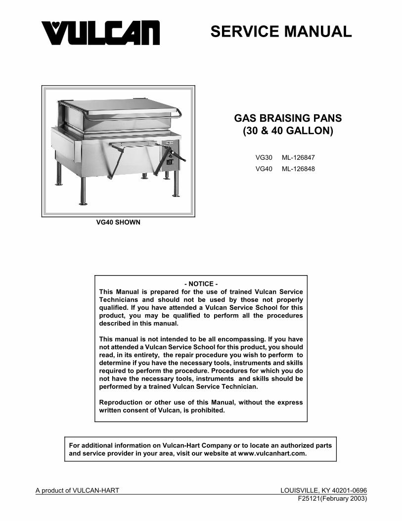
11. Turn on/off switch on and set the temperaturedial to call for heat.
12. Manually operate pan position/down limit switchand observe spark from ignitor.
A. If spark from ignitor is present and lightsthe gas for pilot burner, and pilot burnerremains lit, then the system is workingproperly.
B. If pilot burner lights but does not maintainan adequate flame during the trial forignition (90 seconds):
1) Check pilot burner orifice for clogging.
CAUTION: If orifice is clogged with debris, cleanwith air or non-flammable liquid only.
2) Check pilot burner flame adjustmentas outlined under SERVICEPROCEDURES ANDADJUSTMENTS.
C. If spark from ignitor is present but does notlight the pilot gas before ignition controlmodule locks out, there may not beenough gas in the supply line for ignition.
Release the pan position/down limit switchto remove power and re-set the module.Wait 5 minutes between ignition tries forunburned gas to vent.
Manually operate pan position/down limitswitch and sparking should resume. Themodule may need to be re-set severaltimes before ignition takes place.
1) If pilot burner ignition is successful,release the pan position/down limitswitch, turn the on/off switch to offand re-connect main valve (MV) leadwire on the ignition control module.
D. If ignitor is still not sparking, turn the on/offswitch off, disconnect power to themachine and turn the gas supply off.
13. Install a replacement ignition control moduleand check for proper operation.
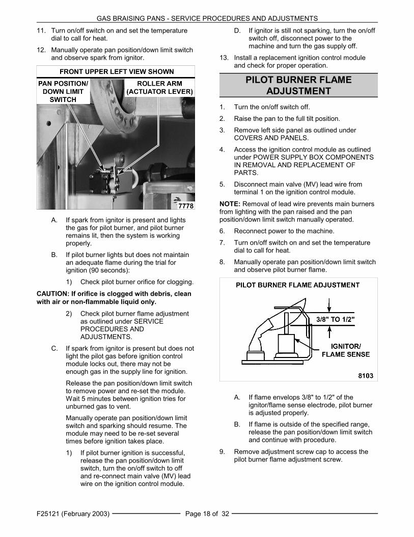
PILOT BURNER FLAMEADJUSTMENT
1. Turn the on/off switch off.
2. Raise the pan to the full tilt position.
3. Remove left side panel as outlined underCOVERS AND PANELS.
4. Access the ignition control module as outlinedunder POWER SUPPLY BOX COMPONENTSIN REMOVAL AND REPLACEMENT OFPARTS.
5. Disconnect main valve (MV) lead wire fromterminal 1 on the ignition control module.
NOTE: Removal of lead wire prevents main burnersfrom lighting with the pan raised and the panposition/down limit switch manually operated.
6. Reconnect power to the machine.
7. Turn on/off switch on and set the temperaturedial to call for heat.
8. Manually operate pan position/down limit switchand observe pilot burner flame.
A. If flame envelops 3/8" to 1/2" of theignitor/flame sense electrode, pilot burneris adjusted properly.
B. If flame is outside of the specified range,release the pan position/down limit switchand continue with procedure.
9. Remove adjustment screw cap to access thepilot burner flame adjustment screw.

GAS BRAISING PANS - SERVICE PROCEDURES AND ADJUSTMENTS
F25121 (February 2003)Page 19 of 32
10. Manually operate pan position/down limit switchand observe pilot burner flame.
A. To increase pilot flame, turn the screwcounterclockwise. To decrease pilot flame,turn the screw clockwise.
11. Once the pilot flame has been adjustedcorrectly, release the pan position/down limitswitch, turn the on/off switch off and replace theadjustment screw cap.
12. Re-connect main valve (MV) lead wire fromterminal 1 on the ignition control module.
13. Lower the pan to the full down position andcheck for proper operation.
FLAME SENSE CURRENT TESTNOTE: You must complete the SPARK IGNITIONTEST prior to checking flame sense current.
If pilot burner lights but will not maintain flame,perform the following test.
1. Turn the on/off switch off.
2. Access the ignition control module as outlinedunder POWER SUPPLY BOX COMPONENTSIN REMOVAL AND REPLACEMENT OFPARTS.
3. Remove jumper wire between terminals markedwith an asterisk (*) & 8.
4. Set VOM to micro amp scale (DC) and connectthe black meter lead (-) to the asterisk (*)terminal and red meter lead (+) to terminal 8.
5. Turn on/off switch on and set the temperaturedial to call for heat.
6. With pilot burner lit, meter reading should beabove 1.0 micro amp (minimum) and steady.
A. If reading is greater than or equal to 1.0micro amp then flame sense current iswithin tolerance.
1) Turn on/off switch off and replacejumper wire.
B. If reading is less than 1.0 micro amp andthe condition of the ignitor/flame sense hasbeen verified as good, turn on/off switchoff.
7. Install a replacement ignition control moduleand check for proper operation.
IGNITION CONTROL MODULETEST
1. Lower the pan to the full down position, turn theon/off switch on and set the temperature dial tocall for heat.
GAS BRAISING PANS - SERVICE PROCEDURES AND ADJUSTMENTS
F25121 (February 2003) Page 20 of 32
2. Ignition control module is energized and trialfor ignition starts (90 seconds).
A. Verify 24VAC between terminals 5 & 6.
1) If voltage is not present, seeschematic diagram.
3. Pilot valve (PV) contacts close to energize thepilot valve coil, allowing gas flow to the pilotburner.
A. Verify 24VAC between terminals 2 & 3.
1) If voltage is not present, replaceignition control module and check forproper operation.
4. At the same time, spark voltage is sent fromterminal 9 to the ignitor/flame sense electrodeand sparking begins.
The pilot burner lights, pilot flame is sensed,spark voltage from terminal 9 is removed andsparking stops. Main valve (MV) contacts closeto energize main valve coil, allowing gas flowto the runner tube and main burners.
A. Verify 24VAC between terminals 1 and 2.
1) If voltage is not present, replaceignition control module and check forproper operation.
5. With pilot burner lit, the runner tube lights andmain burners light.
6. As long as the temperature controller is callingfor heat and the ignition control module issensing a sufficient flame sense current, thepilot valve (PV) and main valve (MV) contactswill remain closed.
NOTE: If pilot burner does not immediately light, theignition control module continues sparking for 90seconds, then locks out power to the gascombination valve (pilot valve and main valveremain closed). The module remains locked outuntil the on/off switch is cycled to reset the systemre-start the ignition trial cycle.
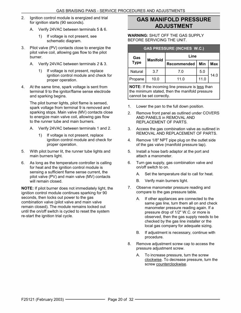
GAS MANIFOLD PRESSUREADJUSTMENT
WARNING: SHUT OFF THE GAS SUPPLYBEFORE SERVICING THE UNIT.
GAS PRESSURE (INCHES W.C.)
GasType Manifold
Line
Recommended Min Max
Natural 3.7 7.0 5.014.0
Propane 10.0 11.0 11.0
NOTE: If the incoming line pressure is less thanthe minimum stated, then the manifold pressurecannot be set correctly.
1. Lower the pan to the full down position.
2. Remove front panel as outlined under COVERSAND PANELS in REMOVAL ANDREPLACEMENT OF PARTS.
3. Access the gas combination valve as outlined inREMOVAL AND REPLACEMENT OF PARTS.
4. Remove 1/8" NPT pipe plug on the outlet sideof the gas valve (manifold pressure tap).
5. Install a hose barb adaptor at the port andattach a manometer.
6. Turn gas supply, gas combination valve andon/off switch to on.
A. Set the temperature dial to call for heat.
B. Verify main burners light.
7. Observe manometer pressure reading andcompare to the gas pressure table.
A. If other appliances are connected to thesame gas line, turn them all on and checkmanometer pressure reading again. If apressure drop of 1/2" W.C. or more isobserved, then the gas supply needs to bechecked by the gas line installer or thelocal gas company for adequate sizing.
B. If adjustment is necessary, continue withprocedure.
8. Remove adjustment screw cap to access thepressure adjustment screw.
A. To increase pressure, turn the screwclockwise. To decrease pressure, turn thescrew counterclockwise.

GAS BRAISING PANS - SERVICE PROCEDURES AND ADJUSTMENTS
F25121 (February 2003)Page 21 of 32
FRONT VIEW OF BURNER AIR SHUTTERSHOWN
NOTE: Accurate gas pressure adjustments can onlybe made with the gas on and the main burners lit.
9. Set pressure as listed in gas pressure table.
10. Once the correct pressure has been set, turnthe on/off switch off, replace the adjustmentscrew cap and pipe plug.
11. Check for proper operation.
MAIN BURNERSInspection1. Access the main burners as outlined in
REMOVAL AND REPLACEMENT OF PARTS.
2. Inspect burners for clogged ports orobstructions around air shutter. Clean theburner (as necessary) using a soft bristle brush.
3. Inspect gas orifice for clogging. If clogs arefound, remove the orifice and clean with air ornon-flammable liquid only.
NOTE: If the orifice was removed, be sure to installthe orifice in the same location. The outside burnersuse a slightly larger orifice than the center burner(s).
Air Shutter Adjustment1. Verify the gas manifold pressure as outlined
under GAS MANIFOLD PRESSUREADJUSTMENT.
2. Turn the on/off switch off.
3. Remove the control panel as outlined inREMOVAL AND REPLACEMENT OF PARTSto gain viewing access to the right side burner.
4. Turn the on/off switch on and set thetemperature dial to call for heat.
CAUTION: To prevent discoloration of thecooking surface, and possible pan warpage attemperature settings above 250°F, do notoperate the braising pan unless the cookingsurface is covered with water or a thin layer ofcooking oil. 5. Allow burners to remain lit for at least five
minutes.
6. Observe each burners< flame thru the openingin the front of the burner box.
A. If the flame is blue, air shutter is adjustedproperly. A slight tinge of orange in theflame is acceptable.
B. If the flame is yellow tipping, this indicatestoo little primary air (oxygen) for propercombustion. The heating efficiency isreduced, and the amount of soot (carbon)generated as a by-product is increased.Continue with procedure to adjust.
7. Loosen screw on the air shutter for the burnerbeing adjusted. Closing the air shutter willdecrease primary air to the burner and openingthe shutter will increase primary air the burner.
8. Monitor the burner flame and set the air shutteropening as follows:
A. Adjust the air shutter (as necessary) toobtain a blue flame. A slight tinge oforange in the flame is acceptable.
B. After the air shutter adjustment is made,tighten the set screw.
9. Adjust the remaining burners as necessary.

GAS BRAISING PANS - SERVICE PROCEDURES AND ADJUSTMENTS
F25121 (February 2003) Page 22 of 32
SIDE VIEW SHOWN
DC MOTOR CONTROLLER TEST
1. Lower the pan to the full down position.
2. Raise the lid to the full open position.
3. Access the DC motor controller as outlinedunder POWER SUPPLY BOX COMPONENTSin REMOVAL AND REPLACEMENT OFPARTS.
4. Set VOM to measure AC volts and connectmeter leads at L1 & L2 on the controller.
5. Turn the on/off switch to on.
6. Verify 120VAC at L1 & L2 on the controllerwhen the lift control switch (momentary) isoperated to raise & lower the pan.
A. If voltage is present but pan does not raise& lower, proceed to step 7.
B. If voltage is not present refer toMOTORIZED LIFT OPTION ONLY underTROUBLESHOOTING.
7. Disconnect power to the machine.
8. Set VOM to measure DC volts and connect VOM leads to terminals A + (positive) & A -(negative) on the controller.
9. Re-connect power to the machine.
10. Verify 90VDC (approximate) from the DC motorcontroller when the lift control switch(momentary) is operated to raise & lower thepan.
A. If voltage is present but pan does not raise,refer to MOTORIZED LIFT OPTION ONLYunder TROUBLESHOOTING.
B. If voltage is not present and the fuse is ok,turn the on/off switch off and disconnectpower to the machine.
11. Instal a replacement DC motor controller andcheck for proper operation.
PAN POSITION/DOWN LIMITSWITCH ADJUSTMENT
NOTE: Do not use the motorized lift (if installed) forthis procedure.
1. Turn the on/off switch off.
2. Remove front and left side panels as outlinedunder COVERS AND PANELS.
3. Insert the manual crank handle.
4. Raise the pan to the full tilt position.
5. Verify roller arm position on switch.
A. Measure the distance from the rear of theswitch body to the center of the roller. Thedistance should be 3".
B. If distance is ok, proceed to step 6.
C. If distance is not ok, position the roller armas outlined under PAN POSITION/DOWNLIMIT SWITCH in REMOVAL ANDREPLACEMENT OF PARTS.
6. Lower the pan to the full down position. Theroller should make contact with the hinge and operate the switch.
7. Verify pan position/down limit switch N.O.contacts are closing.
A. Turn the on/off switch on and set thetemperature dial to call for heat.
B. Heat light (red) comes on and mainburners light.

GAS BRAISING PANS - SERVICE PROCEDURES AND ADJUSTMENTS
F25121 (February 2003)Page 23 of 32
LEFT SIDE VIEW SHOWN
LEFT SIDE VIEW SHOWN
RIGHT SIDE REAR VIEW SHOWN
1) If main burners do not light, verify24VAC input to the switch, and thatthe voltage is output from the switch.
2) If voltage is present on the outputside of the switch, the switch isfunctioning properly.
3) If voltage is not present, install areplacement pan position/down limit switch and repeat this procedure toadjust.
8. Verify pan position/down limit switch N.O.contacts are opening.
A. Slowly raise the pan until the heat lightand burners go out then stop.
B. At the rear of the pan, measure thedistance from the bottom of the pan skirtto the flat surface covering the frame.
1) Distance should be 2.25" to 2.50".
NOTE: For reference, this is approximately 5angular degrees.
9. If heat light and main burners go out and themeasured distance is within the acceptablerange, switch is adjusted properly. If bothconditions are not satisfied, adjustment isnecessary.
10. To Adjust:
A. Loosen screws on the mounting switchbracket.
B. Adjust mounting switch bracket up ordown (as necessary) to obtain the rearpan dimension of 2.25" to 2.50".
11. Repeat steps 5 thru 9 to check for properoperation.
LID SPRING TENSIONADJUSTMENT
1. Raise the lid and release at several positionsthru the range of travel.
A. If lid remains in place, no adjustment isnecessary.
B. If lid does not remain in place (springs upor falls down), continue with procedure.
NOTE: For spring tension to be set correctly, eachspring must be adjusted the same amount.
2. Remove spring covers by prying up at thebottom. The covers are held in place by tabs onthe bottom of cover.

GAS BRAISING PANS - SERVICE PROCEDURES AND ADJUSTMENTS
F25121 (February 2003) Page 24 of 32
3. To adjust:
A. Place a 1 5/8" wrench on the lid spring locknut and apply a downward force untillocking pin can be removed. Continue tohold lock nut in place.
CAUTION: Do not release wrench while lockingpin is removed or damage to the braising panmay occur.
B. Apply additional downward force toincrease spring tension; or slowly releasedownwards force to decrease springtension.
C. Rotate lid spring lock nut to the next holeposition then replace locking pin. Adjustthe spring tension, one position at a time.
D. Repeat tension adjustment on the oppositespring.
4. Repeat step 1 to verify adjustment. Makeadditional adjustments as necessary.

GAS BRAISING PANS - ELECTRICAL OPERATION
F25121 (February 2003)Page 25 of 32
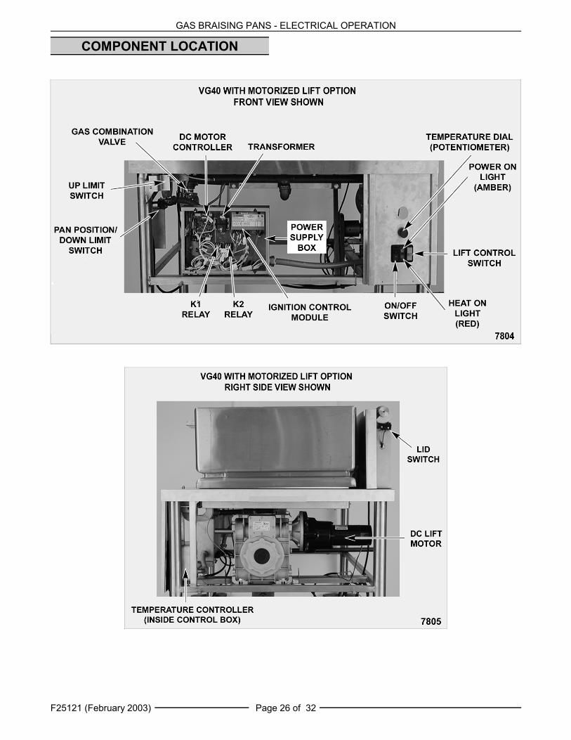
ELECTRICAL OPERATIONCOMPONENT FUNCTION
BRAISING PAN CONTROLSTemperature Controller . . . . Monitors thermocouple input (type E) and regulates braising pan temperature. An
external set point potentiometer is used for temperature adjustments. Transformer . . . . . . . . . . . . . Supplies 24VAC for heating circuit. If motorized pan lift option is installed,
supplies 24VAC for lift control circuit.ON/OFF Switch . . . . . . . . . . Controls 24VAC to the gas heating circuit. If motorized pan lift option is installed,
controls power to lift circuit.Power On Light (Amber) . . . Indicates on/off switch is turned on.Heat Light (Red) . . . . . . . . . . Indicates temperature controller is calling for heat and pan is down.
Pan Position/Down Limit Switch . . . . . . . . N.O. contacts function as pan position switch to power the gas heating circuit
when pan is down. Removes power from gas heating circuit when pan is raised.The N.C. contacts are used for the down limit switch (motorized lift option only).
Ignition Control Module . . . Controls and monitors gas heating. Energizes pilot valve coil to supply gas topilot, generates spark to light gas at the pilot, monitors the presence of flame andenergizes the main valve coil upon a call for heat.
Ignitor/Flame SenseElectrode . . . . . . . . . . . . . . . . Ignites pilot burner and senses the presence of a flame. The Igniter/Flame Sense
is a component of the pilot burner.
Gas CombinationValve . . . . . . . . . . . . . . . . . . . Allows gas flow to the pilot burner when pilot valve coil is energized; and gas flow
to the runner tube & main burners when main valve coil is energized. Also,regulates gas manifold pressure.
MOTORIZED PAN LIFT OPTION CONTROLS
DC Motor Controller . . . . . . . Controls DC lift motor operation for raising & lowering of the pan, and providesmotor acceleration control each time the controller is powered. The controlleroutputs approximately 90VDC to power the motor.
DC Lift Motor . . . . . . . . . . . . . Operates gear reducer to raise or lower the pan. When the correct voltagepolarity is applied thru K1 contacts, motor rotates CW to raise pan. When reversevoltage polarity is applied thru K2 contacts, motor rotates CCW to lower the pan.
Lid Switch . . . . . . . . . . . . . . . Supplies 24VAC power to lift control switch. Used to ensure lid is open before pancan be raised.
Lift Control Switch(Momentary On/Off/On) . . . . Energizes K1 relay coil thru up limit switch contacts (N.C.) to raise the pan.
Energizes K2 relay coil thru down limit switch contacts (N.C.) to lower the pan.The switch positions are: Center neutral (starting) position off; Momentary on -lower pan; Momentary on - raise pan.
Up Limit Switch . . . . . . . . . . Removes power from K1 relay coil when pan reaches full tilt (pan travel stops).
Pan Position/Down Limit Switch . . . . . . . . N.C. contacts function as down limit switch to remove power from K2 relay coil
when pan is lowered to the down position (pan travel stops). The N.O. contactsare used for the pan position switch.
K1 "Up" Relay (3PDT) . . . . . Supplies power to motorized lift circuit to raise the pan when 24VAC coil isenergized.
K2 "Down" Relay (3PDT) . . . Supplies power to motorized lift circuit to lower the pan when 24VAC coil isenergized by the lift control switch. The voltage polarity to the DC motor isreversed thru K2 contacts to turn motor CCW and lower the pan.
GAS BRAISING PANS - ELECTRICAL OPERATION
F25121 (February 2003) Page 26 of 32
COMPONENT LOCATION

GAS BRAISING PANS - ELECTRICAL OPERATION
F25121 (February 2003)Page 27 of 32
IGNITION CONTROL MODULEThe ignition control module is energized when 24 volts is applied between terminals 5 & 6.
The module outputs 24 volts from terminals 2 & 3 to the pilot valve coil (PV) on the gas combination valve,allowing gas flow to the pilot burner.
At the same time, the module generates a spark voltage output of approximately 13K at terminal 9 to beginsparking at the ignitor/flame sense electrode.
The sparking will continue until an adequate pilot flame sense current is sensed by the module or for a maximumof 90 seconds.
NOTE: If pilot is not established within the 90 second ignition trial time, the ignition module locks out by removingpower to the gas combination valve. The system remains locked out until the on/off switch is cycled to reset thesystem and re-start the ignition trial cycle.
With the pilot burner lit, a flame sense current in DC micro amps is rectified thru the ignitor cable back to terminal 9.
When the module senses a sufficient pilot flame current, the module outputs 24 volts from terminal 1 & 2 toenergize the main valve coil (MV) on the gas combination valve, allowing gas flow to the runner tube and mainburners.
When power to the ignition control module is removed, the output voltages are also removed. The pilot valve coil(PV) and the main valve coil (MV) on the gas combination valve are de-energized and close. Gas flow to the pilotburner, runner tube and main burners stop and all burners go out.

GAS BRAISING PANS - ELECTRICAL OPERATION
F25121 (February 2003) Page 28 of 32
SEQUENCE OF OPERATIONRefer to schematic diagram AI1341 for the electricalsequence of operation. Manual pan lift is thestandard configuration.
Heating1. Conditions.
A. 120VAC to braising pan, polarity is correct,and is properly grounded.
1) Temperature controller energized.
2) 24VAC transformer energized.
B. Temperature dial at lowest setting(potentiometer fully CCW).
NOTE: Temperature controller internal relay"HEAT" contacts remain open (N.O.).
C. Pan temperature is below 200/F.
D. On/off switch off.
E. Pan position/down limit switch N.O.contacts closed (pan down).
F. Gas supply on.
G. Gas combination control valve on.
2. Turn on/off switch on.
A. Indicator light (amber) comes on.
3. Set the temperature dial to call for heat.
A. Internal relay on temperature controller isenergized and the "HEAT" contacts close(N.O.).
1) Heat light (red) comes on.
2) Ignition control module.
NOTE: If pan is raised 2.25" to 2.50" at the rear,pan position/down limit switch N.O. contacts willopen and de-energize the heating circuit.
4. Refer to IGNITION CONTROL MODULE.
5. Braising pan reaches set point temperature.
A. Internal relay on temperature controller isde-energized and the "HEAT" contactsopen (N.O.).
1) Heat light (red) goes out.
2) Power is removed from the ignitioncontrol module.
6. Braising pan will continue to cycle with thetemperature controller until the pan is raised orthe on/off switch is turned off.
Motorized Pan Lift (Option)Refer to the dashed line sections labeled"MOTORIZED LIFT OPTION" on the schematicdiagram for the integration of the motorized pan liftcomponents into the sequence of operation.
1. Conditions.
A. 120VAC to braising pan, polarity is correct,and is properly grounded.
B. 24VAC transformer energized.
C. On/off switch off.
D. Lift control switch off (center position).
E. Lid switch N.O. contacts closed (lidopened).
F. Up limit switch N.C. contacts closed (panposition is less than full tilt).
G. Pan position/down limit switch N.O.contacts closed; and N.C. contacts open(pan down).
NOTE: The pan position/down limit switch arecontained in the same switch body. Both sets ofDPST contacts are utilized.
2. Turn on/off switch on.
A. Indicator light (amber) comes on.
NOTE: If the temperature dial is set to call forheat, the ignition trial starts and module beginssparking.
3. Operate the lift control switch to raise the pan(momentary on - raise).
A. K1 relay coil is energized thru the up limitswitch N.C contacts.
1) K1 4/7 N.O. contacts close.
2) K1 9/6 N.O. contacts close.
3) K1 8/5 N.O. contacts close.
B. 120VAC to DC motor controller thru K1 4/7N.O. contacts.
1) 90VDC output is activated at terminalsA + (positive) and A - (negative). DClift motor powered thru K1 9/6 N.O.contacts, K1 8/5 N.O. contacts andpan raises.
4. When the pan is raised 2.25" to 2.50" at therear, pan position/down limit switch contactschange state. The N.O contacts open to removepower from the heating circuit; and the N.Ccontacts close. Power is then available for K2relay coil thru the N.C. set of contacts.
The pan can still be raised or lowered thru itstravel range by operating the lift control switch.Release switch to stop pan travel.

GAS BRAISING PANS - ELECTRICAL OPERATION
F25121 (February 2003)Page 29 of 32
5. Pan reaches full tilt position, the up limit switchN.C. contacts open and K1 relay coil is de-energized.
A. The three sets of K1 contacts return toN.O. position. Power is removed from theDC motor controller, the DC lift motor andpan travel stops.
6. Operate the lift control switch to lower the pan(momentary on - lower).
A. K2 relay coil is energized thru the downlimit switch N.C contacts.
1) K2 4/7 N.O. contacts close.
2) K2 9/6 N.O. contacts close.
3) K2 8/5 N.O. contacts close.
B. 120VAC to DC motor controller thru K2 4/7N.O. contacts.
1) 90VDC output is activated at terminalsA + (positive) and A - (negative). DClift motor powered thru K2 9/6 N.O.contacts, K2 8/5 N.O. contacts andpan lowers.
7. After the pan leaves the full tilt position, the uplimit switch N.C. contacts close. The direction ofpan travel can then be reversed by un-operatingthe switch (pan travel stops) then operating theswitch to raise the pan.
8. Pan reaches full down position, down limitswitch N.C. contacts open and K2 relay coil isde-energized.
A. The three sets of K2 contacts return toN.O. position. Power is removed from theDC motor controller, the DC lift motor andpan travel stops.

GAS BRAISING PANS - ELECTRICAL OPERATION
F25121 (February 2003) Page 30 of 32
SCHEMATIC DIAGRAM

GAS BRAISING PANS - TROUBLESHOOTING
F25121 (February 2003)Page 31 of 32
TROUBLESHOOTINGGAS HEATING (MANUAL LIFT OR MOTORIZED LIFT OPTION)
SYMPTOMS POSSIBLE CAUSESNo spark to ignite pilot burner gas, power onlight is lit.
1. Pan not fully lowered or pan position/down limit switchmalfunction.
2. Temperature dial not set to call for heat or temperaturecontroller malfunction.
3. Ignitor cable open or grounded (short).4. Ignitor spark gap distance incorrect.5. Shorted electrode or an improper ground on
ignitor/flame sense.6. Ignition module not grounded or inoperative.
Spark at ignitor but pilot burner does not light. 1. Gas combination valve off or inoperative.2. Gas supply off or insufficient gas pressure.3. Ignitor spark gap distance incorrect.4. Pilot burner orifice obstructed.5. Ignition Module malfunction.
Pilot burner lights but will not maintain flame. 1. Ignitor/flame sense lead wire connections malfunction.2. Improper ground on pilot burner or ignitor/flame sense;
or ignitor/flame sense malfunction.3. Pilot burner misaligned or Ignitor/flame sense
malfunction.4. Gas pressure not within specified range.5. Incorrect polarity from transformer to Ignition module.6. Ignition Module malfunction.
Main burner(s) do not light or will notmaintain flame.
1. Gas pressure incorrect.2. Runner tube - gas orifice obstructed or malfunction.3. Main burner - gas orifice obstructed or malfunction.4. Main Burner(s) incorrect air shutter position or burner
malfunction.5. Gas combination valve malfunction.
Braising pan does not heat, power on light islit.
1. Temperature controller malfunction.2. Pan position/down limit switch malfunction.3. Ignition module malfunction.4. Gas combination valve malfunction.5. Interconnecting wiring malfunction.
Braising pan does not heat, power on light isnot lit.
1. Main circuit breaker off or power not connected.2. On/off switch off or malfunction.3. Transformer inoperative.4. Interconnecting wiring malfunction.
Excessive or low heat. 1. Temperature probe malfunction.2. Temperature controller malfunction.3. Gas pressure incorrect.4. Gas orifice obstructed or incorrect.
GAS BRAISING PANS - CONDENSED SPARE PARTS LIST
F25121 (February 2003) Printed in U.S.A.
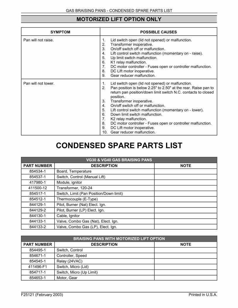
MOTORIZED LIFT OPTION ONLY
SYMPTOM POSSIBLE CAUSES
Pan will not raise. 1. Lid switch open (lid not opened) or malfunction.2. Transformer inoperative.3. On/off switch off or malfunction.4. Lift control switch malfunction (momentary on - raise).5. Up limit switch malfunction.6. K1 relay malfunction.7. DC motor controller - Fuses open or controller malfunction.8. DC Lift motor inoperative.9. Gear reducer malfunction.
Pan will not lower. 1. Lid switch open (lid not opened) or malfunction.2. Pan position is below 2.25" to 2.50" at the rear. Raise pan to
return pan position/down limit switch N.C. contacts to closedposition.
3. Transformer inoperative.4. On/off switch off or malfunction.5. Lift control switch malfunction (momentary on - lower).6. Down limit switch malfunction.7. K2 relay malfunction.8. DC motor controller - Fuses open or controller malfunction.9. DC Lift motor inoperative.10. Gear reducer malfunction.
CONDENSED SPARE PARTS LISTVG30 & VG40 GAS BRAISING PANS
PART NUMBER DESCRIPTION NOTE854534-1 Board, Temperature854537-1 Switch, Control (Manual Lift)417980-1 Module, ignitor411500-12 Transformer, 120-24854517-1 Switch, Limit (Pan Position/Down limit)854512-1 Thermocouple (E-Type)844129-1 Pilot, Burner (Nat) Elect. Ign.844129-2 Pilot, Burner (LP) Elect. Ign.844130-1 Cable, Ignitor844133-1 Valve, Combo Gas (Nat), Elect. Ign.844133-2 Valve, Combo Gas (LP), Elect. Ign.
BRAISING PANS WITH MOTORIZED LIFT OPTIONPART NUMBER DESCRIPTION NOTE
854495-1 Switch, Control854671-1 Controller, Speed854545-1 Relay (24VAC)
411496-F1 Switch, Micro (Lid)854717-1 Switch, Micro (Up Limit)854653-1 Motor, Gear


![Untitled-1 [] · and very easy to use hydraulic table lift which can carry heavy appliances. This table lift is a motorized vehicle that has a platform which can be raised straight](https://img.pdfslide.net/doc/110x75/5ea5fe4f167ac9005542f0f2/untitled-1-and-very-easy-to-use-hydraulic-table-lift-which-can-carry-heavy-appliances.jpg)