Embed Size (px)
Citation preview
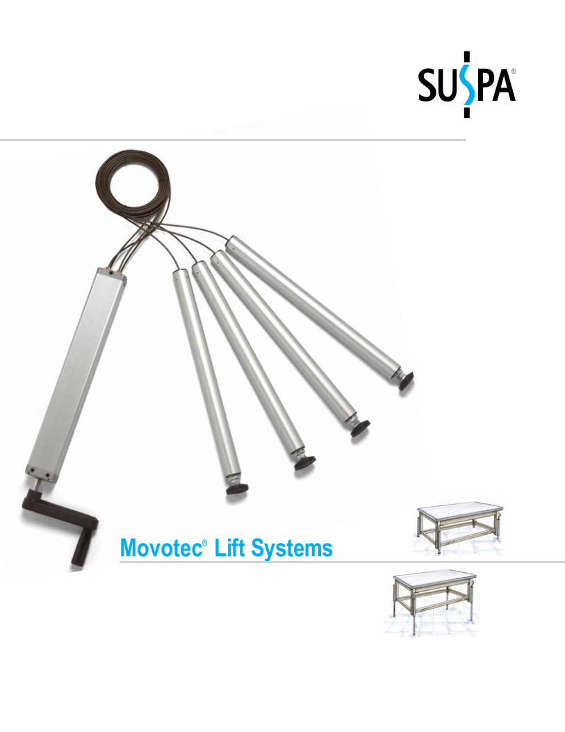
Movotec Lift Systems®
®
“Bolt-On” Lift System 3
Dual Drive Lift System 5
Corner Leg System 7
ATU Lift System 9
Pumps 11
Guided Cylinders 13
Un-Guided Cylinders 15
Crank Handle Options 17
Glides, Casters and Brackets 18
Switches and Accessories 20
Custom System Specification Guide 21
Design Guidelines 23
Standards and Compliance 25
Contents1
2
3
4
7
5
8
9
10
12
11
6
SUSPA - The CompanySUSPA is a world leading supplier of lift, dampening and adjustment mechanisms. Thousands of SUSPA employees across the globe work every day to ensure their customers receive products of the highest quality and the best value. SUSPA is known for innovating solutions that meet specific customer needs, and SUSPA is also highlyrecognized for providing outstanding customer service.
Why Choose Movotec ? Why do so many manufacturers of height adjustable work benches, work stations and work surfaces choose Movotec ?®
®
®
®
®
®
®
Value No other height adjustment system provider compares to Movotec in terms of providing overall value. The Movotec team understands the importance of providing a high quality product, delivered in a timely fashion.
Service - Taking pride in every aspect of the order fulfillment process and providing exceptional customer service is part of the SUSPA Movotec culture. Support - Movotec Lift Systems are backed with a knowl-edgeable staff ready to meet the needs of each individual customer. Comprehensive design implementation (CAD draw-ings and 3-D models), installation and operating instructions are available online 24/7 to ensure all customer expectations are met.
Warranty - As part of SUSPA’s quality sales and exceptional service, all Movotec products come with a factory warranty. It’s SUSPA’s way of making sure the products delivered to our valued customers perform as promised. For details about the SUSPA Movotec warranty, please see “Terms of Sale” on our website at http://www.suspa.com/us/footer/terms-of-trade/
Quality - For the last few decades and continuing today, SUSPA products are recognized in the industry for top quality. Movotec products are engineered to the highest quality utilizing ISO9001 standards. In addition, Movotec products are manu-factured at a production facility that meets the ISO/TS 16949 quality standards. The highest quality products are the result of employee pride, empowerment, customer loyalty and a commit-ment to be the best.
Technology Years of experience, engineering and research have resulted in a product that goes well beyond the competition. Whether it be a proprietary process or patented product, Movotec remains the technology leader.
Sealing Technology - Providing superior sealing technol-ogy means a product that performs at peak levels, requires no maintenance, and provides years and years of flawless per-formance. Only Movotec uses its unique combination of engi-neered fluids, sealing surfaces and sealing materials. Proprietary Manufacturing Operations - Much of Movotec’s superior performance is the result of highly refined manufacturing operations. Years of experience and engineering have resulted in consistently producing a highly reliable prod-uct. Our customers can feel the difference when they grasp the crank handle or press the switch and see the results. Fluid Properties - Movotec NT15 is a specially formulated oil that is clear, odorless, reduces friction, has superior sealing qualities, and is safe for all applications, including food processing.
Motor Technology - Do the comparison: Put any motorized lift system next to a Movotec System and compare noise level, speed, ease of use and features. Movotec provides the motor control technology designed for years of service, with program-mable features and built-in intelligence. Patented Products /Features - Many times it is the unique products and features offered that keep SUSPA Movotec customers among those with the highest level of customer satisfaction. The Movotec ATU and numerous cylinders are patented and are used in SUSPA Movotec exclusively.
®
®
®
®®
®
®
®
®®
®
®
®
®
®
®
®
13
For drawings, CAD models and more information visit www.suspamovotec.com
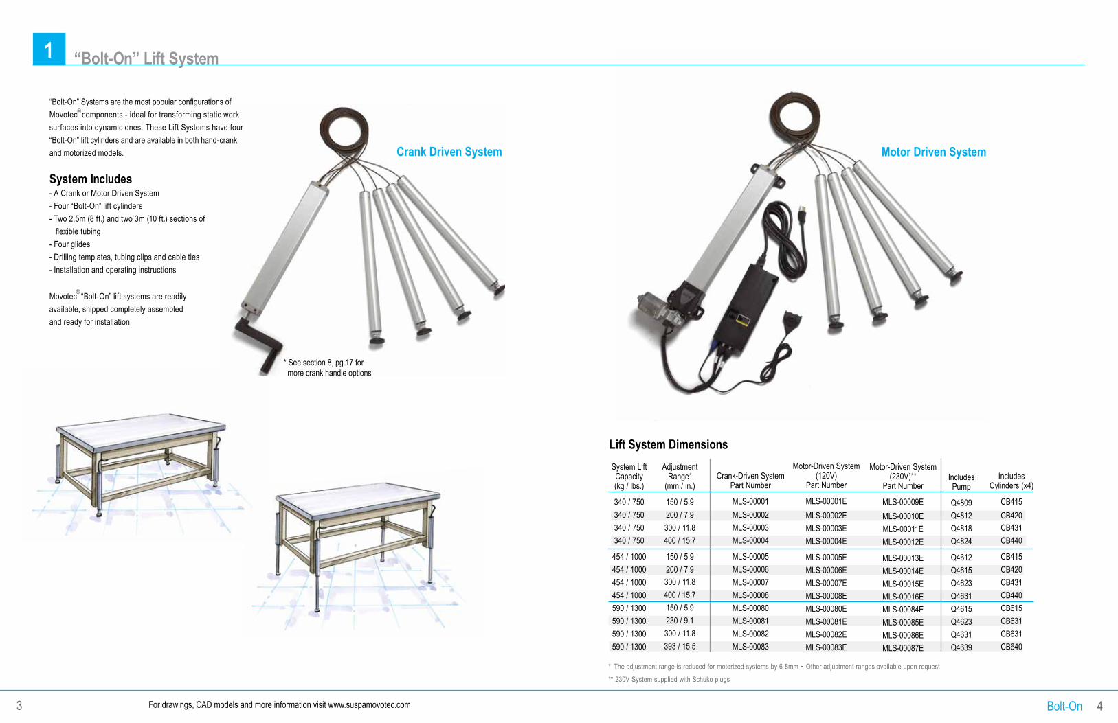
Motor Driven System
Lift System DimensionsSystem Lift Capacity (kg / lbs.)
340 / 750340 / 750340 / 750340 / 750
454 / 1000454 / 1000454 / 1000454 / 1000590 / 1300590 / 1300590 / 1300590 / 1300
Adjustment Range*
(mm / in.)
150 / 5.9200 / 7.9300 / 11.8400 / 15.7
150 / 5.9200 / 7.9300 / 11.8400 / 15.7150 / 5.9230 / 9.1300 / 11.8393 / 15.5
Crank-Driven System Part Number
MLS-00001MLS-00002MLS-00003MLS-00004
MLS-00005MLS-00006MLS-00007MLS-00008MLS-00080MLS-00081MLS-00082MLS-00083
Motor-Driven System (120V)
Part Number
MLS-00001EMLS-00002EMLS-00003EMLS-00004E
MLS-00005EMLS-00006EMLS-00007EMLS-00008EMLS-00080EMLS-00081EMLS-00082EMLS-00083E
Includes Pump
Q4809Q4812Q4818Q4824
Q4612Q4615Q4623Q4631Q4615Q4623Q4631Q4639
Includes Cylinders (x4)
CB415CB420CB431CB440
CB415CB420CB431CB440CB615CB631CB631CB640
* The adjustment range is reduced for motorized systems by 6-8mm - Other adjustment ranges available upon request
** 230V System supplied with Schuko plugs
1 “Bolt-On” Lift System
“Bolt-On” Systems are the most popular configurations of Movotec components - ideal for transforming static work surfaces into dynamic ones. These Lift Systems have four “Bolt-On” lift cylinders and are available in both hand-crank and motorized models.
System Includes- A Crank or Motor Driven System- Four “Bolt-On” lift cylinders- Two 2.5m (8 ft.) and two 3m (10 ft.) sections of flexible tubing- Four glides- Drilling templates, tubing clips and cable ties- Installation and operating instructions
Movotec “Bolt-On” lift systems are readily available, shipped completely assembled and ready for installation.
Crank Driven System
Bolt-On 43
Motor-Driven System (230V)**
Part Number
MLS-00009EMLS-00010EMLS-00011EMLS-00012E
MLS-00013EMLS-00014EMLS-00015EMLS-00016EMLS-00084EMLS-00085EMLS-00086EMLS-00087E
®
®
* See section 8, pg.17 for more crank handle options
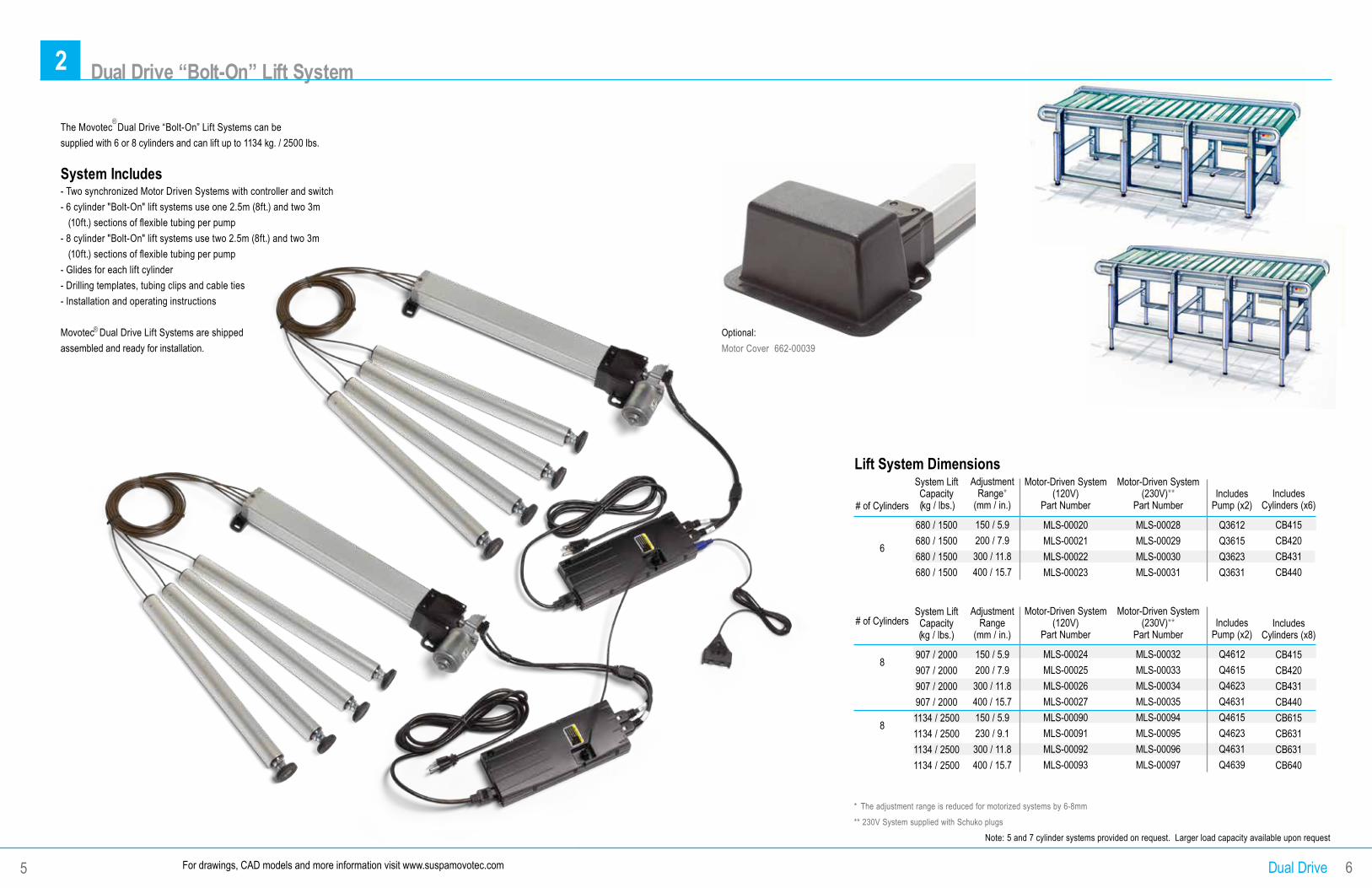
2 Dual Drive “Bolt-On” Lift System
Lift System DimensionsSystem Lift Capacity (kg / lbs.)
680 / 1500680 / 1500680 / 1500680 / 1500
System Lift Capacity (kg / lbs.)
907 / 2000907 / 2000907 / 2000907 / 20001134 / 25001134 / 25001134 / 25001134 / 2500
Adjustment Range*
(mm / in.)
150 / 5.9200 / 7.9300 / 11.8400 / 15.7
Adjustment Range
(mm / in.)
150 / 5.9200 / 7.9300 / 11.8400 / 15.7150 / 5.9230 / 9.1300 / 11.8400 / 15.7
Motor-Driven System (120V)
Part Number
MLS-00020MLS-00021MLS-00022MLS-00023
Motor-Driven System (120V)
Part Number
MLS-00024MLS-00025MLS-00026MLS-00027MLS-00090MLS-00091MLS-00092MLS-00093
Includes Pump (x2)
Q3612Q3615Q3623Q3631
Includes Pump (x2)
Q4612Q4615Q4623Q4631Q4615Q4623Q4631Q4639
# of Cylinders
6
# of Cylinders
8
8
* The adjustment range is reduced for motorized systems by 6-8mm
** 230V System supplied with Schuko plugs
Note: 5 and 7 cylinder systems provided on request. Larger load capacity available upon request
Dual Drive 6
Motor-Driven System (230V)**
Part Number
MLS-00028MLS-00029MLS-00030MLS-00031
Motor-Driven System (230V)**
Part Number
MLS-00032MLS-00033MLS-00034MLS-00035MLS-00094MLS-00095MLS-00096MLS-00097
Optional:Motor Cover 662-00039
For drawings, CAD models and more information visit www.suspamovotec.com5
®The Movotec Dual Drive “Bolt-On” Lift Systems can be supplied with 6 or 8 cylinders and can lift up to 1134 kg. / 2500 lbs.
System Includes- Two synchronized Motor Driven Systems with controller and switch- 6 cylinder "Bolt-On" lift systems use one 2.5m (8ft.) and two 3m (10ft.) sections of flexible tubing per pump- 8 cylinder "Bolt-On" lift systems use two 2.5m (8ft.) and two 3m (10ft.) sections of flexible tubing per pump- Glides for each lift cylinder- Drilling templates, tubing clips and cable ties- Installation and operating instructions
Movotec Dual Drive Lift Systems are shipped assembled and ready for installation.
®
Includes Cylinders (x6)
CB415CB420CB431CB440
Includes Cylinders (x8)
CB415CB420CB431CB440CB615CB631CB631CB640
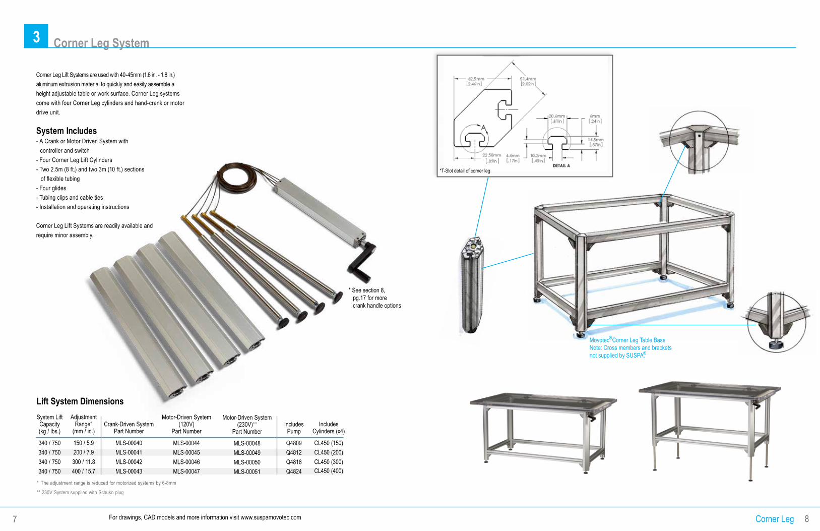
3 Corner Leg System
* The adjustment range is reduced for motorized systems by 6-8mm
** 230V System supplied with Schuko plug
Lift System DimensionsSystem Lift Capacity (kg / lbs.)
340 / 750340 / 750340 / 750340 / 750
Adjustment Range*
(mm / in.)
150 / 5.9200 / 7.9300 / 11.8400 / 15.7
Motor-Driven System (120V)
Part Number
MLS-00044MLS-00045MLS-00046MLS-00047
Crank-Driven System Part Number
MLS-00040MLS-00041MLS-00042MLS-00043
Includes Pump
Q4809Q4812Q4818Q4824
Includes Cylinders (x4)
CL450 (150)CL450 (200)CL450 (300) CL450 (400)
Corner Leg Lift Systems are used with 40-45mm (1.6 in. - 1.8 in.) aluminum extrusion material to quickly and easily assemble a height adjustable table or work surface. Corner Leg systems come with four Corner Leg cylinders and hand-crank or motor drive unit.
System Includes- A Crank or Motor Driven System with controller and switch- Four Corner Leg Lift Cylinders- Two 2.5m (8 ft.) and two 3m (10 ft.) sections of flexible tubing- Four glides- Tubing clips and cable ties- Installation and operating instructions
Corner Leg Lift Systems are readily available and require minor assembly.
Corner Leg 8
Motor-Driven System (230V)**
Part Number
MLS-00048MLS-00049MLS-00050MLS-00051
For drawings, CAD models and more information visit www.suspamovotec.com7
Movotec Corner Leg Table BaseNote: Cross members and brackets not supplied by SUSPA.
®
®
* See section 8, pg.17 for more crank handle options
*T-Slot detail of corner leg
680mm(26.7 in.)
686mm(27 in.)
560mm(22 in.)
800mm (31.5 in.)1000mm (39.4 in.),
or1200mm (47.2 in.)
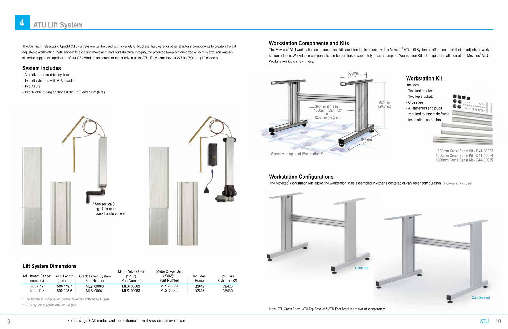
System Includes- A crank or motor drive system- Two lift cylinders with ATU bracket- Two ATU’s- Two flexible tubing sections 0.9m (3ft.) and 1.8m (6 ft.)
Adjustment Range* (mm / in.) 200 / 7.9
300 / 11.8
ATU Length(mm / in.)500 / 19.7 600 / 23.6
Crank Driven SystemPart NumberMLS-00060MLS-00061
Motor Driven Unit(120V)
Part NumberMLS-00062MLS-00063
Lift System Dimensions
Workstation KitIncludes:- Two foot brackets- Two top brackets- Cross beam- All fasteners and plugs required to assemble frame- Installation instructions
800mm Cross Beam Kit - D44-000331000mm Cross Beam Kit - D44-000341200mm Cross Beam Kit - D44-00035
ATU 10
4 ATU Lift System
Motor Driven Unit(230V)**
Part NumberMLS-00064MLS-00065
IncludesPumpQ2812 Q2818
IncludesCylinder (x2)
CE420 CE430
* The adjustment range is reduced for motorized systems by 6-8mm
** 230V System supplied with Schuko plug
The Aluminum Telescoping Upright (ATU) Lift System can be used with a variety of brackets, hardware, or other structural components to create a height adjustable workstation. With smooth telescoping movement and rigid structural integrity, the patented two-piece anodized aluminum extrusion was de-signed to support the application of our CE cylinders and crank or motor driven units. ATU lift systems have a 227 kg (500 lbs.) lift capacity.
Workstation Components and KitsThe Movotec ATU workstation components and kits are intended to be used with a Movotec ATU Lift System to offer a complete height adjustable work-station solution. Workstation components can be purchased separately or as a complete Workstation Kit. The typical installation of the Movotec ATU Workstation Kit is shown here.
- Shown with optional Workstation Kit
Workstation ConfigurationsThe Movotec Workstation Kits allows the workstation to be assembled in either a centered or cantilever configuration. (Tabletop not included)
Note: ATU Cross Beam, ATU Top Bracket & ATU Foot Bracket are available separately.
For drawings, CAD models and more information visit www.suspamovotec.com
Centered
Cantilevered
9
® ®
®
®
* See section 8, pg.17 for more crank handle options
5 Pumps
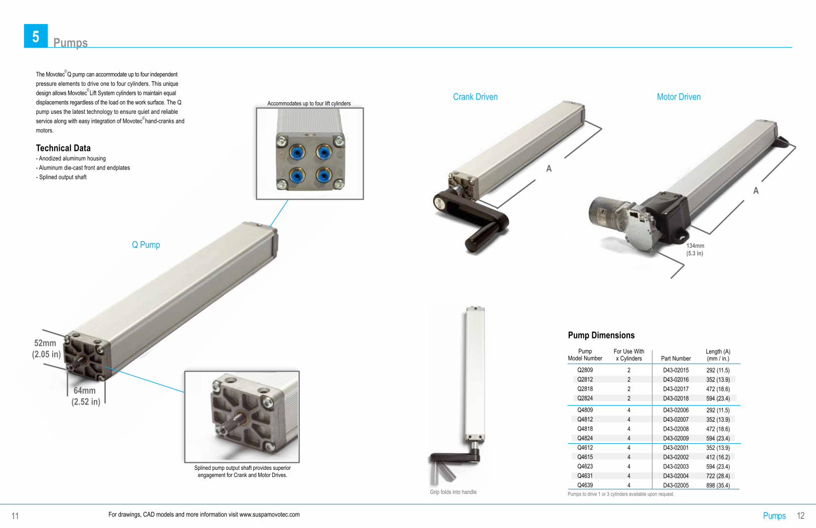
The Movotec Q pump can accommodate up to four independent pressure elements to drive one to four cylinders. This unique design allows Movotec Lift System cylinders to maintain equal displacements regardless of the load on the work surface. The Q pump uses the latest technology to ensure quiet and reliable service along with easy integration of Movotec hand-cranks and motors.
Technical Data- Anodized aluminum housing- Aluminum die-cast front and endplates- Splined output shaft
Q Pump
Pump DimensionsPump
Model Number
Q2809Q2812Q2818Q2824
Q4809Q4812Q4818Q4824Q4612Q4615Q4623Q4631Q4639
For Use With x Cylinders
2222
444444444
Length (A) (mm / in.)
292 (11.5)352 (13.9)472 (18.6)594 (23.4)
292 (11.5)352 (13.9)472 (18.6)594 (23.4)352 (13.9)412 (16.2)594 (23.4)722 (28.4)898 (35.4)
Part Number
D43-02015D43-02016D43-02017D43-02018
D43-02006D43-02007D43-02008D43-02009D43-02001D43-02002D43-02003D43-02004D43-02005
Pumps 12
Accommodates up to four lift cylinders
Splined pump output shaft provides superior engagement for Crank and Motor Drives.
134mm(5.3 in)
Pumps to drive 1 or 3 cylinders available upon request.
Crank Driven
Grip folds into handle
For drawings, CAD models and more information visit www.suspamovotec.com11
®
®
®
Motor Driven
A
A
52mm(2.05 in)
64mm(2.52 in)
6 Guided Cylinders - CB and CN “Bolt-On” Cylinders
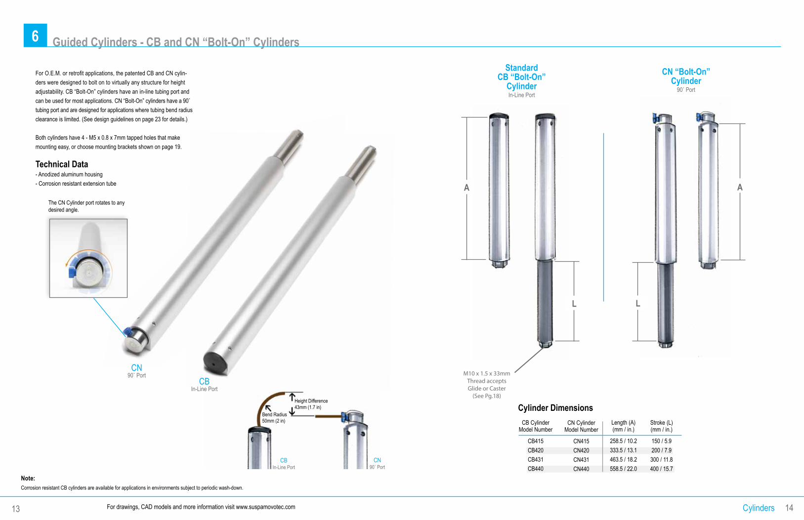
For O.E.M. or retrofit applications, the patented CB and CN cylin-ders were designed to bolt on to virtually any structure for height adjustability. CB “Bolt-On” cylinders have an in-line tubing port and can be used for most applications. CN “Bolt-On” cylinders have a 90˚ tubing port and are designed for applications where tubing bend radius clearance is limited. (See design guidelines on page 23 for details.)
Both cylinders have 4 - M5 x 0.8 x 7mm tapped holes that make mounting easy, or choose mounting brackets shown on page 19.
Technical Data- Anodized aluminum housing - Corrosion resistant extension tube
StandardCB “Bolt-On”
CylinderIn-Line Port
A
L
CN “Bolt-On”Cylinder
90˚ Port
L
A
Cylinders 14
The CN Cylinder port rotates to any desired angle.
Note:Corrosion resistant CB cylinders are available for applications in environments subject to periodic wash-down.
For drawings, CAD models and more information visit www.suspamovotec.com13
Height Difference43mm (1.7 in)
Bend Radius50mm (2 in)
CN90˚ Port
CBIn-Line Port
Cylinder Dimensions
CB Cylinder Model Number
CB415CB420 CB431 CB440
Length (A) (mm / in.)
258.5 / 10.2333.5 / 13.1463.5 / 18.2558.5 / 22.0
CN Cylinder Model Number
CN415CN420CN431CN440
Stroke (L) (mm / in.)
150 / 5.9200 / 7.9300 / 11.8400 / 15.7
CBIn-Line Port
CN90˚ Port M10 x 1.5 x 33mm
Thread accepts Glide or Caster
(See Pg.18)
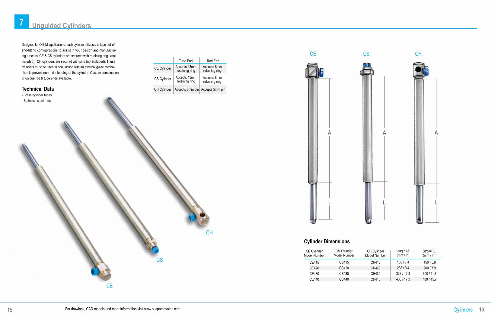
7 Unguided Cylinders
Cylinder Dimensions
CE Cylinder Model Number
CE415CE420CE430CE440
CS Cylinder
Model Number
CS415CS420CS430CS440
CH Cylinder Model Number
CH415CH420CH430CH440
Length (A) (mm / in)
188 / 7.4238 / 9.4338 / 13.3438 / 17.2
Stroke (L) (mm / in.)
150 / 5.9200 / 7.9300 / 11.8400 / 15.7
CE CS CH
A A A
L L L
Cylinders 16For drawings, CAD models and more information visit www.suspamovotec.com
CE
CS
15
Tube End Rod End
Accepts 13mmretaining ring
Accepts 8mmretaining ring
Accepts 8mmretaining ring
Accepts 13mmretaining ring
Accepts 8mm pin Accepts 5mm pin
CS Cylinder
Designed for O.E.M. applications, each cylinder utilizes a unique set of end-fitting configurations to assist in your design and manufactur-ing process. CE & CS cylinders are secured with retaining rings (not included). CH cylinders are secured with pins (not included). These cylinders must be used in conjunction with an external guide mecha-nism to prevent non-axial loading of the cylinder. Custom combination or unique rod & tube ends available.
Technical Data- Brass cylinder tubes- Stainless steel rods
CH
CE Cylinder
CH Cylinder
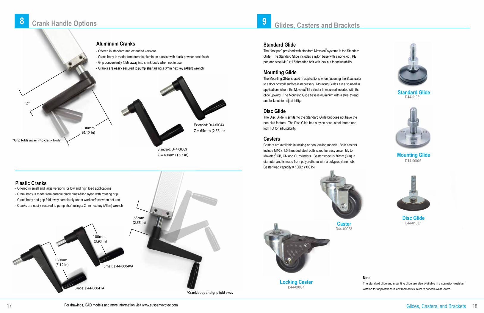
Plastic Cranks- Offered in small and large versions for low and high load applications- Crank body is made from durable black glass-filled nylon with rotating grip- Crank body and grip fold away completely under worksurface when not use- Cranks are easily secured to pump shaft using a 2mm hex key (Allen) wrench
9 Glides, Casters and Brackets
Standard GlideThe “foot pad” provided with standard Movotec systems is the Standard Glide. The Standard Glide includes a nylon base with a non-skid TPE pad and steel M10 x 1.5 threaded bolt with lock nut for adjustability.
Mounting GlideThe Mounting Glide is used in applications when fastening the lift actuator to a floor or work surface is necessary. Mounting Glides are also used in applications where the Movotec lift cylinder is mounted inverted with the glide upward. The Mounting Glide base is aluminum with a steel thread and lock nut for adjustability.
Disc GlideThe Disc Glide is similar to the Standard Glide but does not have the non-skid feature. The Disc Glide has a nylon base, steel thread and lock nut for adjustability.
CastersCasters are available in locking or non-locking models. Both casters include M10 x 1.5 threaded steel bolts sized for easy assembly to Movotec CB, CN and CL cylinders. Caster wheel is 76mm (3 in) in diameter and is made from polyurethene with a polypropylene hub.Caster load capacity = 136kg (300 lb)
Note:The standard glide and mounting glide are also available in a corrosion-resistant version for applications in environments subject to periodic wash-down.
Standard Glide
Mounting GlideD44-00003
D44-01031
Glides, Casters, and Brackets 18
Disc Glide644-01037
Locking CasterD44-00037
For drawings, CAD models and more information visit www.suspamovotec.com17
®
®
®
D44-00038Caster
8 Crank Handle Options
Small: D44-00040A
Large: D44-00041A
Standard: D44-00039Z = 40mm (1.57 in)
130mm (5.12 in)
100mm (3.93 in)
130mm (5.12 in)
"Z"
*Grip folds away into crank body
*Crank body and grip fold away
65mm(2.55 in)
Aluminum Cranks- Offered in standard and extended versions- Crank body is made from durable aluminum diecast with black powder coat finish- Grip conveniently folds away into crank body when not in use- Cranks are easily secured to pump shaft using a 3mm hex key (Allen) wrench
Extended: D44-00043Z = 65mm (2.55 in)
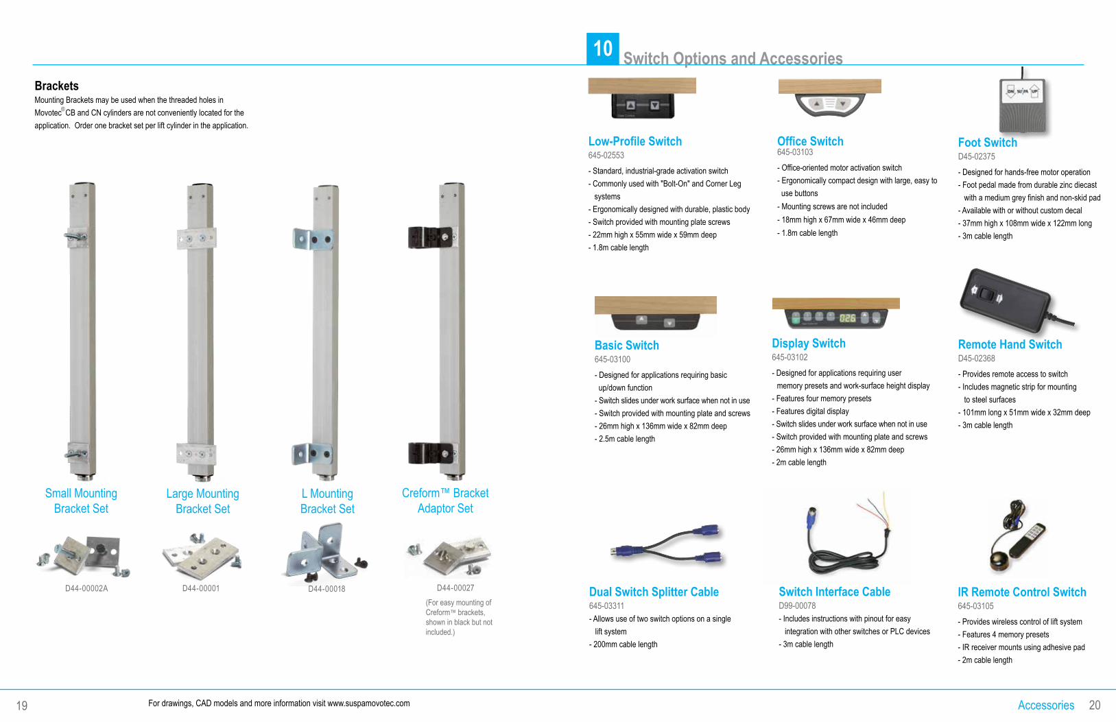
Foot Switch D45-02375 - Designed for hands-free motor operation - Foot pedal made from durable zinc diecast with a medium grey finish and non-skid pad - Available with or without custom decal - 37mm high x 108mm wide x 122mm long - 3m cable length
Dual Switch Splitter Cable 645-03311 - Allows use of two switch options on a single lift system - 200mm cable length
Switch Interface Cable D99-00078 - Includes instructions with pinout for easy integration with other switches or PLC devices - 3m cable length
10 Switch Options and Accessories
Low-Profile Switch 645-02553 - Standard, industrial-grade activation switch - Commonly used with "Bolt-On" and Corner Leg systems - Ergonomically designed with durable, plastic body - Switch provided with mounting plate screws - 22mm high x 55mm wide x 59mm deep - 1.8m cable length
Office Switch 645-03103 - Office-oriented motor activation switch - Ergonomically compact design with large, easy to use buttons- Mounting screws are not included- 18mm high x 67mm wide x 46mm deep- 1.8m cable length
Remote Hand Switch D45-02368 - Provides remote access to switch - Includes magnetic strip for mounting to steel surfaces - 101mm long x 51mm wide x 32mm deep - 3m cable length
Display Switch 645-03102 - Designed for applications requiring user memory presets and work-surface height display - Features four memory presets - Features digital display - Switch slides under work surface when not in use - Switch provided with mounting plate and screws - 26mm high x 136mm wide x 82mm deep - 2m cable length
Accessories 20For drawings, CAD models and more information visit www.suspamovotec.com
IR Remote Control Switch 645-03105 - Provides wireless control of lift system - Features 4 memory presets - IR receiver mounts using adhesive pad - 2m cable length
19
BracketsMounting Brackets may be used when the threaded holes in Movotec CB and CN cylinders are not conveniently located for the application. Order one bracket set per lift cylinder in the application.
Small MountingBracket Set
Large MountingBracket Set
L MountingBracket Set
Creform™ Bracket Adaptor Set
D44-00002A D44-00001 D44-00018 D44-00027(For easy mounting of Creform™ brackets, shown in black but not included.)
®
Basic Switch 645-03100 - Designed for applications requiring basic up/down function - Switch slides under work surface when not in use - Switch provided with mounting plate and screws - 26mm high x 136mm wide x 82mm deep - 2.5m cable length
11 Custom System Specification Guide
Lifting Capacity
113 kg / 250 lb
227 kg / 500 lb
340 kg / 750 lb
340 kg / 750 lb
454 kg / 1000 lb
590 kg / 1300 lb
680 kg / 1500 lb
907 kg / 2000 lb
1134 kg / 2500 lb
# of Cylinders
1
2
3
4
6
8
8
Adjustment Range 150 mm / 5.9 in200 mm / 7.9 in300 mm / 11.8 in400 mm / 15.8 in
150 mm / 5.9 in200 mm / 7.9 in300 mm / 11.8 in400 mm / 15.8 in
150 mm / 5.9 in200 mm / 7.9 in300 mm / 11.8 in400 mm / 15.8 in
150 mm / 5.9 in200 mm / 7.9 in300 mm / 11.8 in400 mm / 15.8 in
150 mm / 5.9 in200 mm / 7.9 in300 mm / 11.8 in400 mm / 15.8 in
150 mm / 5.9 in230 mm / 9.1 in300 mm / 11.8 in400 mm / 15.8 in
150 mm / 5.9 in200 mm / 7.9 in300 mm / 11.8 in400 mm / 15.8 in
150 mm / 5.9 in200 mm / 7.9 in300 mm / 11.8 in400 mm / 15.8 in
150 mm / 5.9 in230 mm / 9.1 in300 mm / 11.8 in400 mm / 15.7 in
Pump Model # Q1809Q1812Q1818Q1824
Q2809Q2812Q2818Q2824
Q3612Q3615Q3623Q3631
Q4809Q4812Q4818Q4824
Q4612Q4615Q4623Q4631
Q4615Q4623Q4631Q4639
Q3612Q3615Q3623Q3631
Q4612Q4615Q4623Q4631
PB4615PB4623PB4631PB4639
Specification Guide 22
1
1 2 3 4
2
3
4
5
5
For drawings, CAD models and more information visit www.suspamovotec.com21
®
®
Cylinder Model # 415 420 430 440
415 420 430 440
415 420 430 440
415 420 430 440
415 420 430 440
615 620 630 640
415 420 430 440
415 420 430 440
615 631 631 640
System Model # 1Q8- 4150-1Q8- 4200-1Q8- 4300-1Q8- 4400-
2Q8- 4150-2Q8- 4200-2Q8- 4300-2Q8- 4400-
3Q6- 4150-3Q6- 4200-3Q6- 4300-3Q6- 4400-
4Q8- 4150-4Q8- 4200-4Q8- 4300-4Q8- 4400-
4Q6- 4150-4Q6- 4200-4Q6- 4300-4Q6- 4400-
4Q6- 6150- 4Q6- 6200- 4Q6- 6300- 4Q6- 6400-
6Q6- 4150-E L 6Q6- 4200-E L 6Q6- 4300-E L 6Q6- 4400-E L
8Q6- 4150-E L 8Q6- 4200-E L 8Q6- 4300-E L 8Q6- 4400-E L
8Q6- 6150-E L 8Q6- 6200-E L 8Q6- 6300-E L 8Q6- 6400-E L
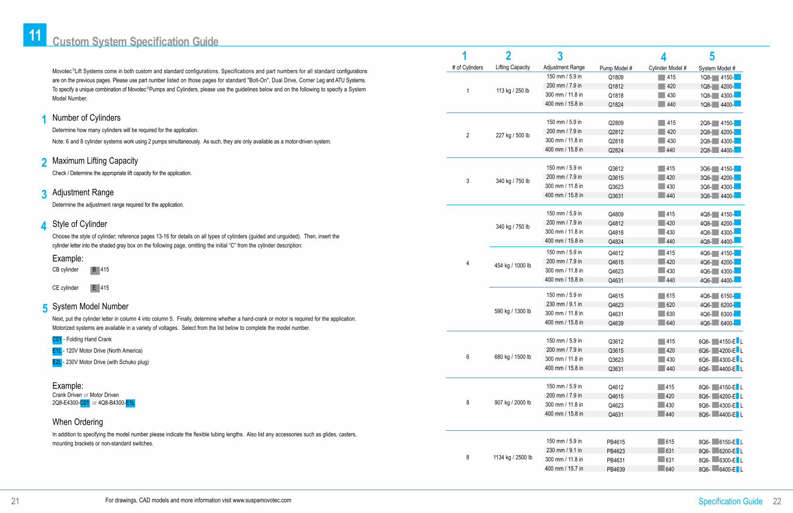
Movotec Lift Systems come in both custom and standard configurations. Specifications and part numbers for all standard configurations are on the previous pages. Please use part number listed on those pages for standard "Bolt-On", Dual Drive, Corner Leg and ATU Systems. To specify a unique combination of Movotec Pumps and Cylinders, please use the guidelines below and on the following to specify a System Model Number.
Number of CylindersDetermine how many cylinders will be required for the application.
Note: 6 and 8 cylinder systems work using 2 pumps simultaneously. As such, they are only available as a motor-driven system.
Maximum Lifting CapacityCheck / Determine the appropriate lift capacity for the application.
Adjustment RangeDetermine the adjustment range required for the application.
Style of CylinderChoose the style of cylinder; reference pages 13-16 for details on all types of cylinders (guided and unguided). Then, insert the cylinder letter into the shaded gray box on the following page, omitting the initial “C” from the cylinder description:
Example:CB cylinder B 415 CE cylinder E 415
System Model NumberNext, put the cylinder letter in column 4 into column 5. Finally, determine whether a hand-crank or motor is required for the application. Motorized systems are available in a variety of voltages. Select from the list below to complete the model number.
C01 - Folding Hand Crank
E1L - 120V Motor Drive (North America)
E2L - 230V Motor Drive (with Schuko plug)
Example:Crank Driven or Motor Driven 2Q8-E4300-C01 or 4Q8-B4300-E1L
When OrderingIn addition to specifying the model number please indicate the flexible tubing lengths. Also list any accessories such as glides, casters, mounting brackets or non-standard switches.
12 Design Guidelines
Design Guide 24For drawings, CAD models and more information visit www.suspamovotec.com23
®
10,000CYCLES
®
®
®
®
®
HOWTO:
®
®
®
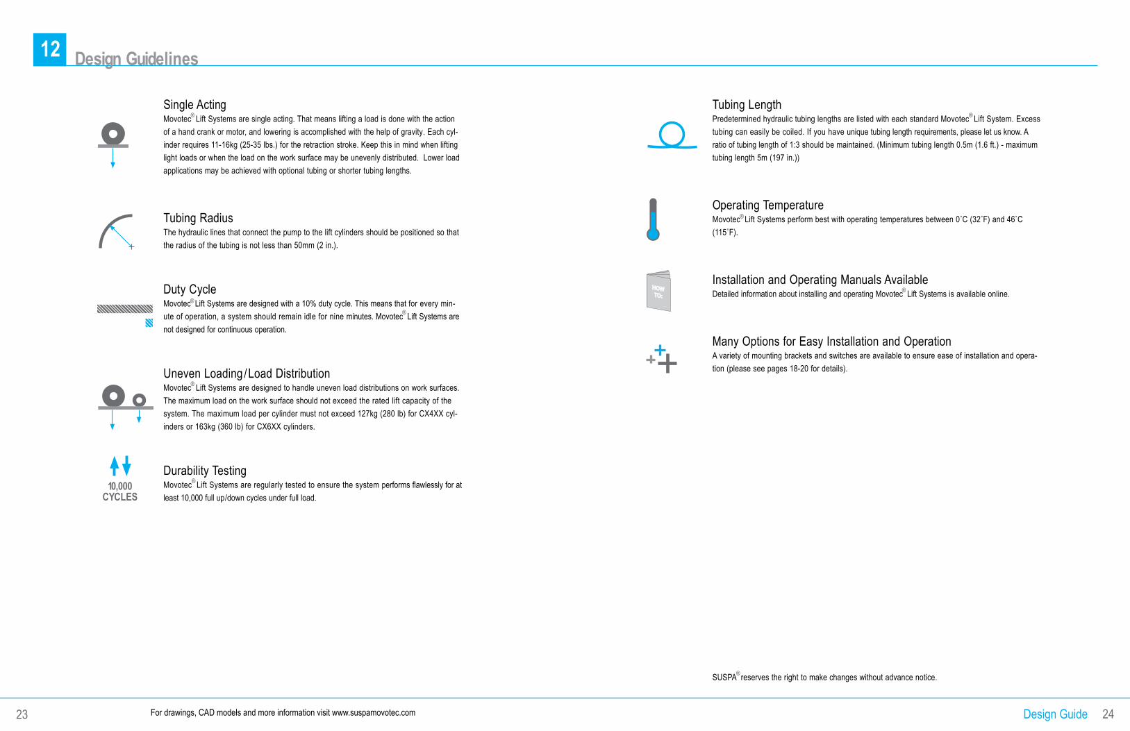
Single Acting Movotec Lift Systems are single acting. That means lifting a load is done with the action of a hand crank or motor, and lowering is accomplished with the help of gravity. Each cyl-inder requires 11-16kg (25-35 lbs.) for the retraction stroke. Keep this in mind when lifting light loads or when the load on the work surface may be unevenly distributed. Lower load applications may be achieved with optional tubing or shorter tubing lengths.
Tubing Radius The hydraulic lines that connect the pump to the lift cylinders should be positioned so that the radius of the tubing is not less than 50mm (2 in.).
Duty Cycle Movotec Lift Systems are designed with a 10% duty cycle. This means that for every min-ute of operation, a system should remain idle for nine minutes. Movotec Lift Systems are not designed for continuous operation.
Uneven Loading /Load Distribution Movotec Lift Systems are designed to handle uneven load distributions on work surfaces. The maximum load on the work surface should not exceed the rated lift capacity of the system. The maximum load per cylinder must not exceed 127kg (280 lb) for CX4XX cyl-inders or 163kg (360 lb) for CX6XX cylinders.
Durability Testing Movotec Lift Systems are regularly tested to ensure the system performs flawlessly for at least 10,000 full up/down cycles under full load.
Tubing Length Predetermined hydraulic tubing lengths are listed with each standard Movotec Lift System. Excess tubing can easily be coiled. If you have unique tubing length requirements, please let us know. A ratio of tubing length of 1:3 should be maintained. (Minimum tubing length 0.5m (1.6 ft.) - maximum tubing length 5m (197 in.))
Operating Temperature Movotec Lift Systems perform best with operating temperatures between 0˚C (32˚F) and 46˚C (115˚F).
Installation and Operating Manuals Available Detailed information about installing and operating Movotec Lift Systems is available online.
Many Options for Easy Installation and Operation A variety of mounting brackets and switches are available to ensure ease of installation and opera-tion (please see pages 18-20 for details).
SUSPA reserves the right to make changes without advance notice.
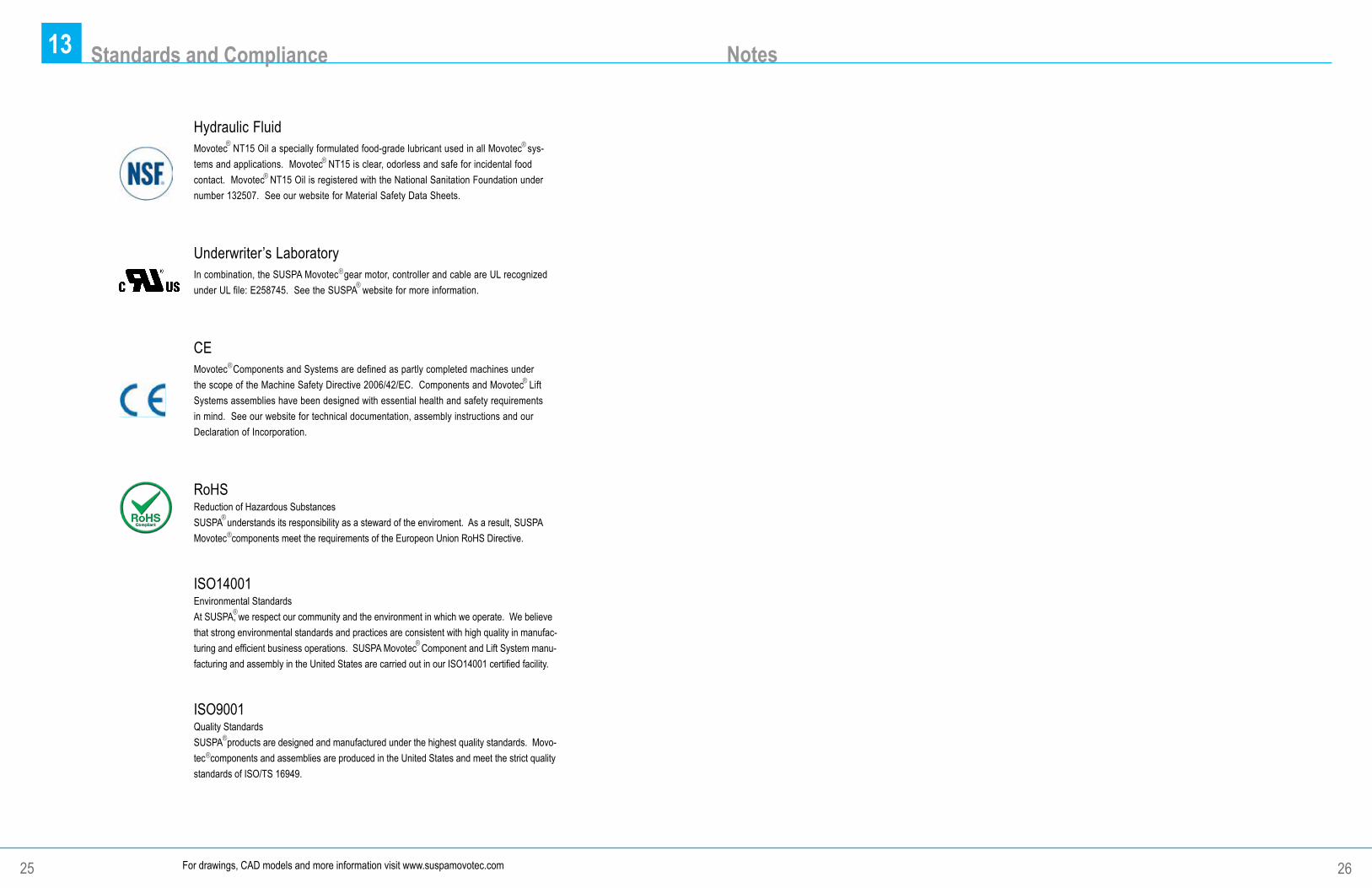
Hydraulic FluidMovotec NT15 Oil a specially formulated food-grade lubricant used in all Movotec sys-tems and applications. Movotec NT15 is clear, odorless and safe for incidental food contact. Movotec NT15 Oil is registered with the National Sanitation Foundation under number 132507. See our website for Material Safety Data Sheets.
Underwriter’s LaboratoryIn combination, the SUSPA Movotec gear motor, controller and cable are UL recognized under UL file: E258745. See the SUSPA website for more information.
CEMovotec Components and Systems are defined as partly completed machines under the scope of the Machine Safety Directive 2006/42/EC. Components and Movotec Lift Systems assemblies have been designed with essential health and safety requirements in mind. See our website for technical documentation, assembly instructions and our Declaration of Incorporation.
RoHSReduction of Hazardous SubstancesSUSPA understands its responsibility as a steward of the enviroment. As a result, SUSPA Movotec components meet the requirements of the Europeon Union RoHS Directive.
ISO14001Environmental StandardsAt SUSPA, we respect our community and the environment in which we operate. We believe that strong environmental standards and practices are consistent with high quality in manufac-turing and efficient business operations. SUSPA Movotec Component and Lift System manu-facturing and assembly in the United States are carried out in our ISO14001 certified facility.
ISO9001Quality StandardsSUSPA products are designed and manufactured under the highest quality standards. Movo-tec components and assemblies are produced in the United States and meet the strict quality standards of ISO/TS 16949.
12 Notes
26For drawings, CAD models and more information visit www.suspamovotec.com
13 Standards and Compliance
25
®
®
® ®
®
®
®
®
®
®
®
®
®
®

SUSPA Incorporated3970 Roger B. Chaffee Mem Drive, SEGrand Rapids, MI 49548-3497 USAPhone 616 241 4200Fax 616 241 4347www.suspa.comLit -00091 1213-1500
®