Embed Size (px)
Citation preview
530
CNC Knopfannähautomat
CNC Automat for Button Sewing
Bedienanleitung / Operating Instructions
Aufstellanleitung / Installation Instructions
Serviceanleitung / Service Instructions
Postfach 17 03 51, D-33703 Bielefeld � Potsdamer Straße 190, D-33719 Bielefeld
Telefon +49 (0) 5 21/ 9 25-00 � Telefax +49 (0) 5 21/ 9 25 24 35 � www.duerkopp-adler.com
1
2
3
Ausgabe / Edition: Änderungsindex Teile-Nr./Part.-No.:
06/2008 Rev. index: 01.0 Printed in Federal Republic of Germany 0791 530001
Anleitung, komplett
Manual, complete
530
Alle Rechte vorbehalten.
Eigentum der Dürkopp Adler AG und urheberrechtlich geschützt. Jede, auch auszugsweise
Wiederverwendung dieser Inhalte ist ohne vorheriges schriftliches Einverständnis der Dürkopp Adler AG
verboten.
All rights reserved.
Property of Dürkopp Adler AG and copyrighted. Reproduction or publication of the content in any manner,
even in extracts, without prior written permission of Dürkopp Adler AG, is prohibited.
Copyright © Dürkopp Adler AG - 2008
Übersicht Summary
Bedienanleitung
Aufstellanleitung
Serviceanleitung
Bauschaltplan
9890 510001 B
Operating Instructions
Installation Instructions
Service Instructions
Interconnection-diagram
9890 510001 B
Foreword
This instruction manual is intended to help the user to become familiar
with the machine and take advantage of its application possibilities in
accordance with the recommendations.
The instruction manual contains important information on how to
operate the machine securely, properly and economically. Observation
of the instructions eliminates danger, reduces costs for repair and
down-times, and increases the reliability and life of the machine.
The instruction manual is intended to complement existing national
accident prevention and environment protection regulations.
The instruction manual must always be available at the machine/sewing
unit.
The instruction manual must be read and applied by any person that is
authorized to work on the machine/sewing unit. This means:
– Operation, including equipping, troubleshooting during the work
cycle, removing of fabric waste,
– Service (maintenance, inspection, repair) and/or
– Transport.
The user also has to assure that only authorized personnel work on the
machine.
The user is obliged to check the machine at least once per shift for
apparent damages and to immediatly report any changes (including the
performance in service), which impair the safety.
The user company must ensure that the machine is only operated in
perfect working order.
Never remove or disable any safety devices.
If safety devices need to be removed for equipping, repairing or
maintaining, the safety devices must be remounted directly after
completion of the maintenance and repair work.
Unauthorized modification of the machine rules out liability of the
manufacturer for damage resulting from this.
Observe all safety and danger recommendations on the machine/unit!
The yellow-and-black striped surfaces designate permanend danger
areas, eg danger of squashing, cutting, shearing or collision.
Besides the recommendations in this instruction manual also observe
the general safety and accident prevention regulations!
General safety instructions
The non-observance of the following safety instructions can cause bodily injuries or damages to the machine.
1. The machine must only be commissioned in full knowledge of the
instruction book and operated by persons with appropriate training.
2. Before putting into service also read the safety rules and
instructions of the motor supplier.
3. The machine must be used only for the purpose intended. Use of
the machine without the safety devices is not permitted. Observe all
the relevant safety regulations.
4. When gauge parts are exchanged (e.g. needle, presser foot, needle
plate, feed dog and bobbin) when threading, when the workplace is
left, and during service work, the machine must be disconnected
from the mains by switching off the master switch or disconnecting
the mains plug.
5. Daily servicing work must be carried out only by appropriately
trained persons.
6. Repairs, conversion and special maintenance work must only be
carried out by technicians or persons with appropriate training.
7. For service or repair work on pneumatic systems, disconnect the
machine from the compressed air supply system (max. 7-10 bar).
Before disconnecting, reduce the pressure of the maintenance unit.
Exceptions to this are only adjustments and functions checks made
by appropriately trained technicians.
8. Work on the electrical equipment must be carried out only by
electricians or appropriately trained persons.
9. Work on parts and systems under electric current is not permitted,
except as specified in regulations DIN VDE 0105.
10. Conversion or changes to the machine must be authorized by us
and made only in adherence to all safety regulations.
11. For repairs, only replacement parts approved by us must be used.
12. Commissioning of the sewing head is prohibited until such time as
the entire sewing unit is found to comply with EC directives.
13. The line cord should be equipped with a country-specific mains
plug. This work must be carried out by appropriately trained
technicians (see paragraph 8).
It is absolutely necessary to respect the safety
instructions marked by these signs.
Danger of bodily injuries !
Please note also the general safety instructions.

Index Page:
Preface and general safety hints
Part 1: Operating Instructions Class 530
(Edition 06/2008)
1. Description of product . . . . . . . . . . . . . . . . . . . . . . . . . . . . . . . . . . . . . . . . . . 5
2. Description of proper use . . . . . . . . . . . . . . . . . . . . . . . . . . . . . . . . . . . . . . . 6
3. Subclasses . . . . . . . . . . . . . . . . . . . . . . . . . . . . . . . . . . . . . . . . . . . . . . . . . 6
4. Optional equipment . . . . . . . . . . . . . . . . . . . . . . . . . . . . . . . . . . . . . . . . . . . . 7
5. Stands . . . . . . . . . . . . . . . . . . . . . . . . . . . . . . . . . . . . . . . . . . . . . . . . . . . . 7
6. Technical data
6.1 Technical data of the subclasses . . . . . . . . . . . . . . . . . . . . . . . . . . . . . . . . . . . . . 8
7. Operating
7.1 Threading needle thread. . . . . . . . . . . . . . . . . . . . . . . . . . . . . . . . . . . . . . . . . . 9
7.2 Adjust needle thread tension . . . . . . . . . . . . . . . . . . . . . . . . . . . . . . . . . . . . . . . 10
7.3 Open needle thread tension . . . . . . . . . . . . . . . . . . . . . . . . . . . . . . . . . . . . . . . 10
7.4 Adjust thread regulator . . . . . . . . . . . . . . . . . . . . . . . . . . . . . . . . . . . . . . . . . . . 11
7.5 Wind on bobbin thread . . . . . . . . . . . . . . . . . . . . . . . . . . . . . . . . . . . . . . . . . . . 12
7.6 Change hook thread bobbin . . . . . . . . . . . . . . . . . . . . . . . . . . . . . . . . . . . . . . . . 13
7.7 Adjust bobbin thread tension . . . . . . . . . . . . . . . . . . . . . . . . . . . . . . . . . . . . . . . 14
7.8 Change needle . . . . . . . . . . . . . . . . . . . . . . . . . . . . . . . . . . . . . . . . . . . . . . . 15
7.9 Button shank shaper . . . . . . . . . . . . . . . . . . . . . . . . . . . . . . . . . . . . . . . . . . . . 16
7.10 Setting the hook feet of button clamp . . . . . . . . . . . . . . . . . . . . . . . . . . . . . . . . . . 17
8. Operating the control of class 530
8.1 The control panel . . . . . . . . . . . . . . . . . . . . . . . . . . . . . . . . . . . . . . . . . . . . . . 18
8.1.1 The keys . . . . . . . . . . . . . . . . . . . . . . . . . . . . . . . . . . . . . . . . . . . . . . . . . . . 18
8.2 User interface . . . . . . . . . . . . . . . . . . . . . . . . . . . . . . . . . . . . . . . . . . . . . . . . 20
8.2.1 Structure of menu . . . . . . . . . . . . . . . . . . . . . . . . . . . . . . . . . . . . . . . . . . . . . . 20
8.3 Alter numerical values, parameter values, selection of alternatives . . . . . . . . . . . . . . . . 21
8.3.1 Alter numerical values . . . . . . . . . . . . . . . . . . . . . . . . . . . . . . . . . . . . . . . . . . . 21
8.3.2 Selection of a parameter . . . . . . . . . . . . . . . . . . . . . . . . . . . . . . . . . . . . . . . . . . 22
8.3.3 Selection of alternatives . . . . . . . . . . . . . . . . . . . . . . . . . . . . . . . . . . . . . . . . . . 22
8.4 Sewing patterns . . . . . . . . . . . . . . . . . . . . . . . . . . . . . . . . . . . . . . . . . . . . . . . 23
8.5 Main menu . . . . . . . . . . . . . . . . . . . . . . . . . . . . . . . . . . . . . . . . . . . . . . . . . . 24
8.5.1 Sewing pattern operation . . . . . . . . . . . . . . . . . . . . . . . . . . . . . . . . . . . . . . . . . 24
1
Index Page:
8.5.2 Programming mode . . . . . . . . . . . . . . . . . . . . . . . . . . . . . . . . . . . . . . . . . . . . . 29
8.5.3 Sewing pattern sequences . . . . . . . . . . . . . . . . . . . . . . . . . . . . . . . . . . . . . . . . 31
8.5.3.1 Switching the sequence programming mode on/off . . . . . . . . . . . . . . . . . . . . . . . . . 31
8.5.3.2 Sequence programming mode . . . . . . . . . . . . . . . . . . . . . . . . . . . . . . . . . . . . . . 34
8.5.4 Technician mode . . . . . . . . . . . . . . . . . . . . . . . . . . . . . . . . . . . . . . . . . . . . . . 35
8.5.4.1 Machine configuration . . . . . . . . . . . . . . . . . . . . . . . . . . . . . . . . . . . . . . . . . . . 38
8.5.4.2 User configuration . . . . . . . . . . . . . . . . . . . . . . . . . . . . . . . . . . . . . . . . . . . . . 45
8.5.4.3 Service functions . . . . . . . . . . . . . . . . . . . . . . . . . . . . . . . . . . . . . . . . . . . . . . 49
8.5.4.4 Free contours . . . . . . . . . . . . . . . . . . . . . . . . . . . . . . . . . . . . . . . . . . . . . . . . 63
8.5.4.5 Memory dongle . . . . . . . . . . . . . . . . . . . . . . . . . . . . . . . . . . . . . . . . . . . . . . . 71
8.6 Error messages . . . . . . . . . . . . . . . . . . . . . . . . . . . . . . . . . . . . . . . . . . . . . . . 78
8.6.1 Error categories . . . . . . . . . . . . . . . . . . . . . . . . . . . . . . . . . . . . . . . . . . . . . . . 78
8.6.2 Application messages . . . . . . . . . . . . . . . . . . . . . . . . . . . . . . . . . . . . . . . . . . . 79
8.6.3 Machine errors . . . . . . . . . . . . . . . . . . . . . . . . . . . . . . . . . . . . . . . . . . . . . . . 81
9. Sewing . . . . . . . . . . . . . . . . . . . . . . . . . . . . . . . . . . . . . . . . . . . . . . . . . . . . 86
10. Maintenance
10.1 Cleaning and checking . . . . . . . . . . . . . . . . . . . . . . . . . . . . . . . . . . . . . . . . . . . 87
10.2 Oil lubrication . . . . . . . . . . . . . . . . . . . . . . . . . . . . . . . . . . . . . . . . . . . . . . . . 88
11. Standard sewing patterns . . . . . . . . . . . . . . . . . . . . . . . . . . . . . . . . . . . . . . . . 89
12. Clamping feet . . . . . . . . . . . . . . . . . . . . . . . . . . . . . . . . . . . . . . . . . . . . . . . . 92
13. Numbering of menu items . . . . . . . . . . . . . . . . . . . . . . . . . . . . . . . . . . . . . . . . 93
1
1. Description of product
The Dürkopp Adler 530 is a CNC double lockstitch automat for button
sewing. The available button patterns are adjustable in length, width
and speed and can be memorized in their modified form. It is also
possible to create “free” sewing patterns (by programming).
The button sewing automat is equipped with automatic sewing foot
lifts, thread trimmer, thread retractor and integrated DC direct drive.
Technical features
– The control is executed by the DAC III, that is operated by the user
with the control panel BF2B.
– The fabric drive or the clamp drive is effectuated by two step
motors.
– The oil wick lubrication is central for head and hook, but there exist
two separated oil reservoirs that are both supplied through one
upper reservoir. So there is only one reservoir to be refilled.
– A maximum of 50 standard button patterns is available.
These standard patterns can temporarily be modified (as regards
length, width and speed). When switching off the automat the
modified data of the last sewing pattern are maintained.
– 40 modified sewing patterns can additionally be memorized.
– Additionally there are a maximum of 9 free seam contours with a
total of 5000 dynamically controlled stitches at the users
disposition. Thus it is possible to sew f. e. free button patterns. The
coordinates of free sewing patterns are entered at the control
panel. There is no need for further devices.
– 25 sewing pattern sequence programs each with up to 20 sewing
patterns per sewing pattern sequence program can be created and
memorized.
– The exactitude of the entered coordinates comes to 0.1 mm.
– It is possible to lock certain button programs or button sequence
programs and/or the modification so that an unauthorized use or
modification can be prohibited by the technicians.
– An in between cut without releasing the button clamp is possible,
so as to avoid a continued thread.
– It comes with a bobbin thread counter and a daily production
counter.
– The arm shaft of the button sewing automat is directly powered by
a brushless direct current motor.
– Fabric drive by two step motors.
– The speed can be altered between 0 rpm (manual operation with
full operability of the x-y drive) and 2700 rpm in 100 rpm steps.
– Service and maintenance work is backed up by comprehensive test
programs, that allow a separate testing of single functions.
5
2. Description of proper use
Class 530 is an button sewing automat determined for processing light
to medium-weight material, i.e. fabrics made of textile fibres or leather.
Such sewing materials are used in the clothing industry and for the
production of home and car upholstery.
Furthermore, this button sewing automat can also sew so-called
technical seams. However, in this case the user has to estimate the
possible risks (preferably in cooperation with DÜRKOPP ADLER AG)
because on the one hand such fields of application are comparatively
rare and on the other hand there is an immense variety of possibilities.
According to the result of this estimation suitable safety measures may
have to be taken.
Generally only dry fabrics must be processed on this button sewing
automat. The material must not be thicker than 10 mm when
compressed by the lowered sewing feet. It must not include any hard
objects. The eye protection must be mounted when working with the
automat.
In general the seam is produced with sewing threads made of textile
fibres (cotton threads, synthetic threads or core threads) with the
following dimensions:
Class 530-211 threads of the dimension 50/3 - 120/3
If other threads are to be used, it is indispensable also in this case to
consider the possible risks and to take corresponding safety
measures, if necessary.
This button sewing automat must only be installed and operated in dry
and well-kept rooms. In case it is operated in other rooms which are
not dry and well-kept further measures can become necessary which
have to be agreed upon (see EN 60204-31: 1999).
We as manufacturers of industrial sewing machines take it for granted
that at least semi-skilled operators are working with our products so
that we can assume that all usual operations and their risks are known
to them.
3. Subclasses
Cl. 530-211 Single needle double lockstitch button sewing automat with thread
trimmer and thread wiper.
Equipped with a special button clamp for general button attaching
operations in outer garments and linen. The standard equipment of the
button clamp consists of a clamp insert that can sew buttons of a
diameter from 10 to 20 mm and standard thickness.
6
1
7
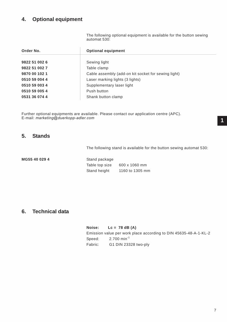
4. Optional equipment
The following optional equipment is available for the button sewing
automat 530:
Order No. Optional equipment
9822 51 002 6 Sewing light
9822 51 002 7 Table clamp
9870 00 102 1 Cable assembly (add-on kit socket for sewing light)
0510 59 004 4 Laser marking lights (3 lights)
0510 59 003 4 Supplementary laser light
0510 59 005 4 Push button
0531 36 074 4 Shank button clamp
Further optional equipments are available. Please contact our application centre (APC).
E-mail: [email protected]
5. Stands
The following stand is available for the button sewing automat 530:
MG55 40 029 4 Stand package
Table top size 600 x 1060 mm
Stand height 1160 to 1305 mm
6. Technical data
Noise: Lc = 78 dB (A)
Emission value per work place according to DIN 45635-48-A-1-KL-2
Speed: 2.700 min-1
Fabric: G1 DIN 23328 two-ply
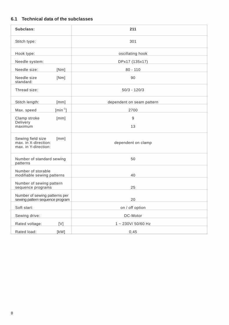
6.1 Technical data of the subclasses
Subclass: 211
Stitch type: 301
Hook type: oscillating hook
Needle system: DPx17 (135x17)
Needle size: [Nm] 80 - 110
Needle size [Nm] 90
standard:
Thread size: 50/3 - 120/3
Stitch length: [mm] dependent on seam pattern
Max. speed [min-1
] 2700
Clamp stroke [mm] 9
Delivery
maximum 13
Sewing field size [mm]
max. in X-direction: dependent on clamp
max. in Y-direction:
Number of standard sewing 50
patterns
Number of storable
modifiable sewing patterns 40
Number of sewing pattern
sequence programs 25
Number of sewing patterns per
sewing pattern sequence program 20
Soft start: on / off option
Sewing drive: DC-Motor
Rated voltage: [V] 1 ~ 230V/ 50/60 Hz
Rated load: [kW] 0,45
8
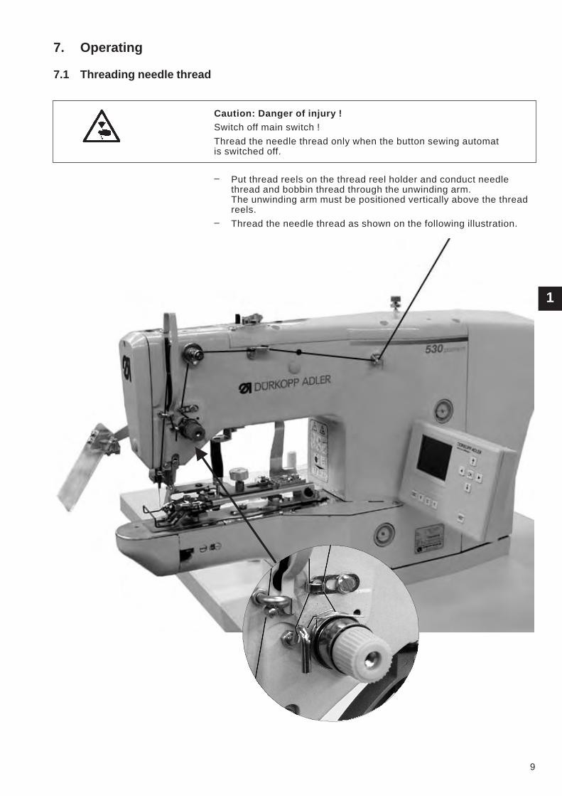
7. Operating
7.1 Threading needle thread
Caution: Danger of injury !
Switch off main switch !
Thread the needle thread only when the button sewing automat
is switched off.
– Put thread reels on the thread reel holder and conduct needle
thread and bobbin thread through the unwinding arm.
The unwinding arm must be positioned vertically above the thread
reels.
– Thread the needle thread as shown on the following illustration.
1
9
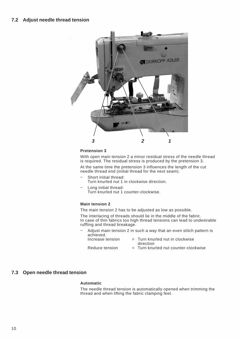
7.2 Adjust needle thread tension
Pretension 3
With open main tension 2 a minor residual stress of the needle thread
is required. The residual stress is produced by the pretension 3.
At the same time the pretension 3 influences the length of the cut
needle thread end (initial thread for the next seam).
– Short initial thread:
Turn knurled nut 1 in clockwise direction.
– Long initial thread:
Turn knurled nut 1 counter-clockwise.
Main tension 2
The main tension 2 has to be adjusted as low as possible.
The interlacing of threads should lie in the middle of the fabric.
In case of thin fabrics too high thread tensions can lead to undesirable
ruffling and thread breakage.
– Adjust main tension 2 in such a way that an even stitch pattern is
achieved.
Increase tension = Turn knurled nut in clockwise
direction
Reduce tension = Turn knurled nut counter-clockwise
7.3 Open needle thread tension
Automatic
The needle thread tension is automatically opened when trimming the
thread and when lifting the fabric clamping feet.
10
3 2 1
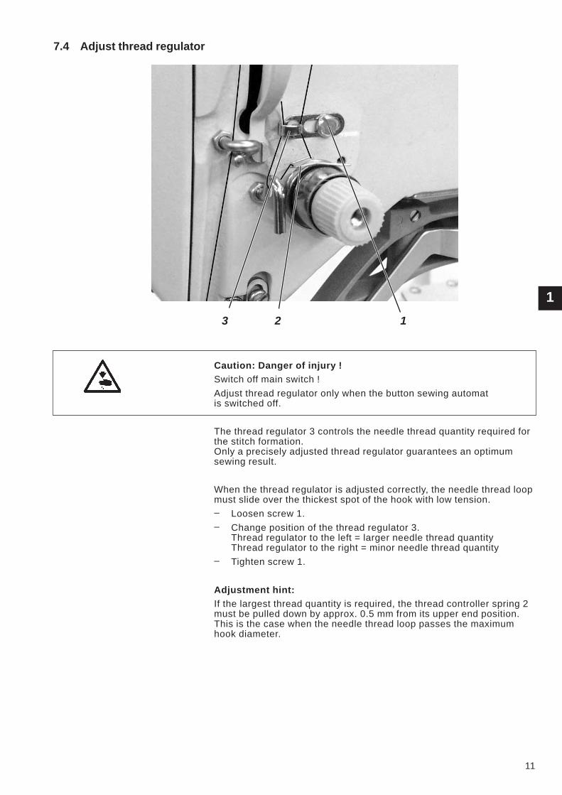
7.4 Adjust thread regulator
Caution: Danger of injury !
Switch off main switch !
Adjust thread regulator only when the button sewing automat
is switched off.
The thread regulator 3 controls the needle thread quantity required for
the stitch formation.
Only a precisely adjusted thread regulator guarantees an optimum
sewing result.
When the thread regulator is adjusted correctly, the needle thread loop
must slide over the thickest spot of the hook with low tension.
– Loosen screw 1.
– Change position of the thread regulator 3.
Thread regulator to the left = larger needle thread quantity
Thread regulator to the right = minor needle thread quantity
– Tighten screw 1.
Adjustment hint:
If the largest thread quantity is required, the thread controller spring 2
must be pulled down by approx. 0.5 mm from its upper end position.
This is the case when the needle thread loop passes the maximum
hook diameter.
1
11
3 2 1
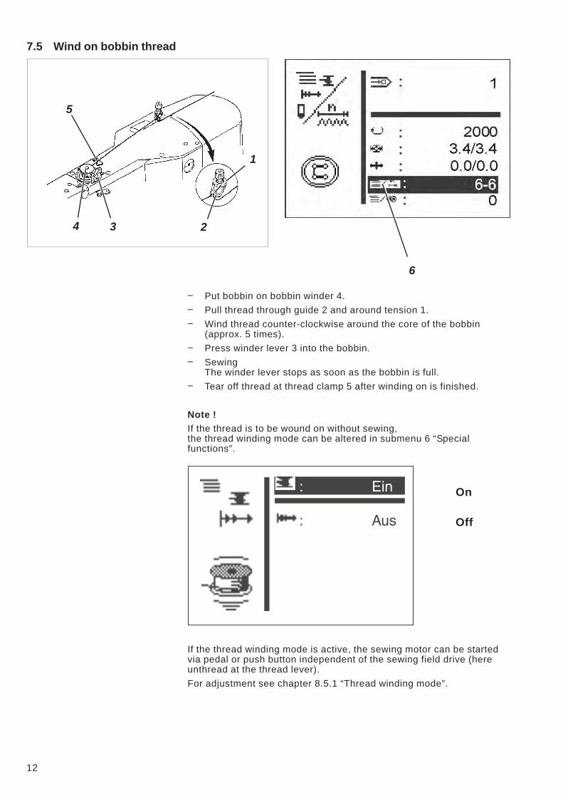
7.5 Wind on bobbin thread
– Put bobbin on bobbin winder 4.
– Pull thread through guide 2 and around tension 1.
– Wind thread counter-clockwise around the core of the bobbin
(approx. 5 times).
– Press winder lever 3 into the bobbin.
– Sewing
The winder lever stops as soon as the bobbin is full.
– Tear off thread at thread clamp 5 after winding on is finished.
Note !
If the thread is to be wound on without sewing,
the thread winding mode can be altered in submenu 6 “Special
functions”.
On
Off
If the thread winding mode is active, the sewing motor can be started
via pedal or push button independent of the sewing field drive (here
unthread at the thread lever).
For adjustment see chapter 8.5.1 “Thread winding mode”.
12
6
1
234
5
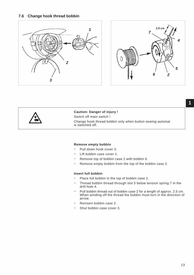
7.6 Change hook thread bobbin
Caution: Danger of injury !
Switch off main switch !
Change hook thread bobbin only when button sewing automat
is switched off.
Remove empty bobbin
– Pull down hook cover 3.
– Lift bobbin case cover 1.
– Remove top of bobbin case 2 with bobbin 6.
– Remove empty bobbin from the top of the bobbin case 2.
Insert full bobbin
– Place full bobbin in the top of bobbin case 2.
– Thread bobbin thread through slot 5 below tension spring 7 in the
drill-hole 4.
– Pull bobbin thread out of bobbin case 2 for a length of approx. 2.5 cm.
When winding off the thread the bobbin must turn in the direction of
arrow.
– Reinsert bobbin case 2.
– Shut bobbin case cover 3.
1
13
1
2
3
4
7
5
26
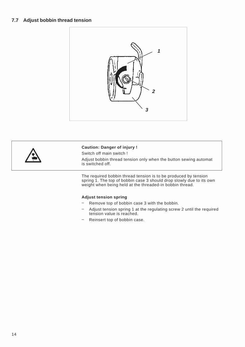
7.7 Adjust bobbin thread tension
Caution: Danger of injury !
Switch off main switch !
Adjust bobbin thread tension only when the button sewing automat
is switched off.
The required bobbin thread tension is to be produced by tension
spring 1. The top of bobbin case 3 should drop slowly due to its own
weight when being held at the threaded-in bobbin thread.
Adjust tension spring
– Remove top of bobbin case 3 with the bobbin.
– Adjust tension spring 1 at the regulating screw 2 until the required
tension value is reached.
– Reinsert top of bobbin case.
14
2
1
3
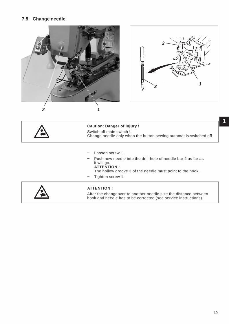
7.8 Change needle
Caution: Danger of injury !
Switch off main switch !
Change needle only when the button sewing automat is switched off.
– Loosen screw 1.
– Push new needle into the drill-hole of needle bar 2 as far as
it will go.
ATTENTION !
The hollow groove 3 of the needle must point to the hook.
– Tighten screw 1.
ATTENTION !
After the changeover to another needle size the distance between
hook and needle has to be corrected (see service instructions).
1
15
2 1
13
2
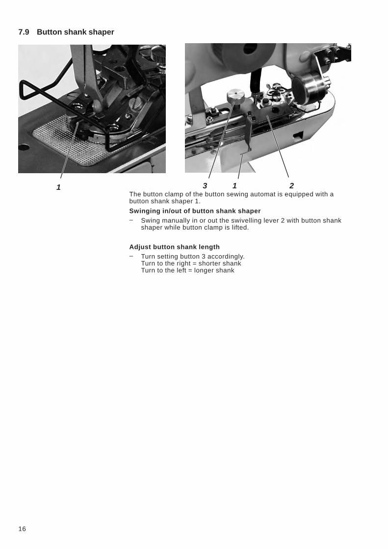
7.9 Button shank shaper
The button clamp of the button sewing automat is equipped with a
button shank shaper 1.
Swinging in/out of button shank shaper
– Swing manually in or out the swivelling lever 2 with button shank
shaper while button clamp is lifted.
Adjust button shank length
– Turn setting button 3 accordingly.
Turn to the right = shorter shank
Turn to the left = longer shank
16
3 1 21
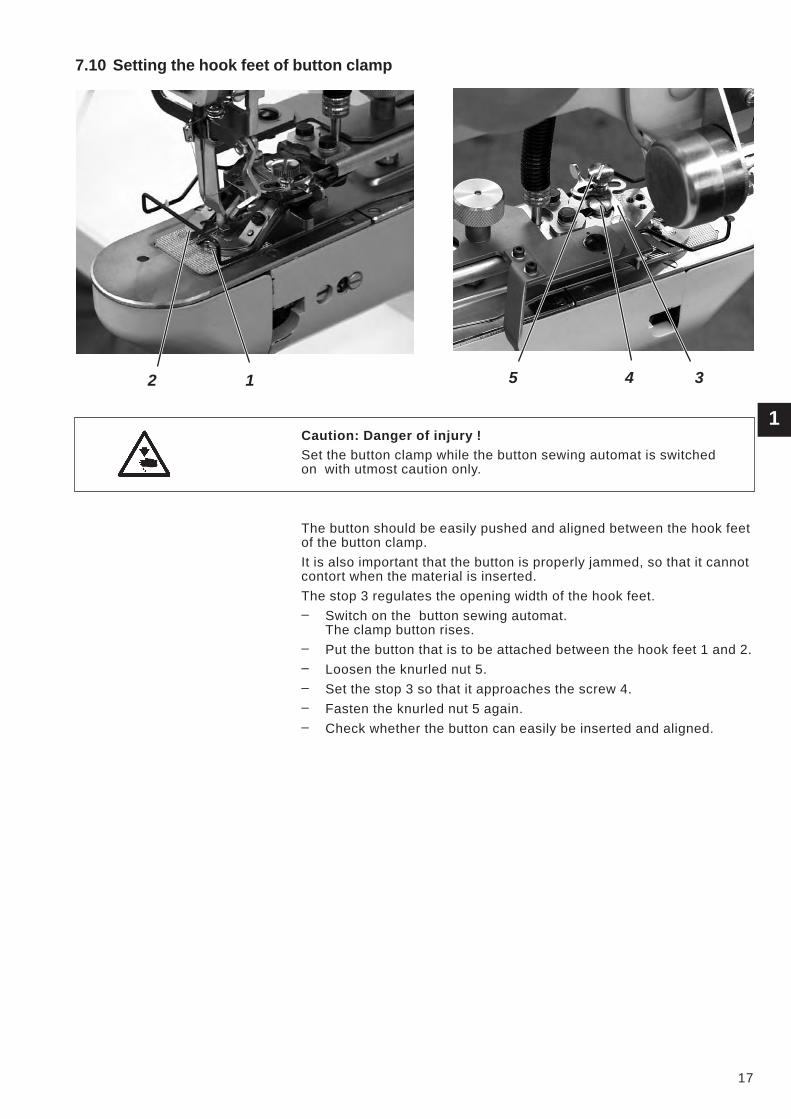
7.10 Setting the hook feet of button clamp
Caution: Danger of injury !
Set the button clamp while the button sewing automat is switched
on with utmost caution only.
The button should be easily pushed and aligned between the hook feet
of the button clamp.
It is also important that the button is properly jammed, so that it cannot
contort when the material is inserted.
The stop 3 regulates the opening width of the hook feet.
– Switch on the button sewing automat.
The clamp button rises.
– Put the button that is to be attached between the hook feet 1 and 2.
– Loosen the knurled nut 5.
– Set the stop 3 so that it approaches the screw 4.
– Fasten the knurled nut 5 again.
– Check whether the button can easily be inserted and aligned.
1
17
2 1 5 4 3
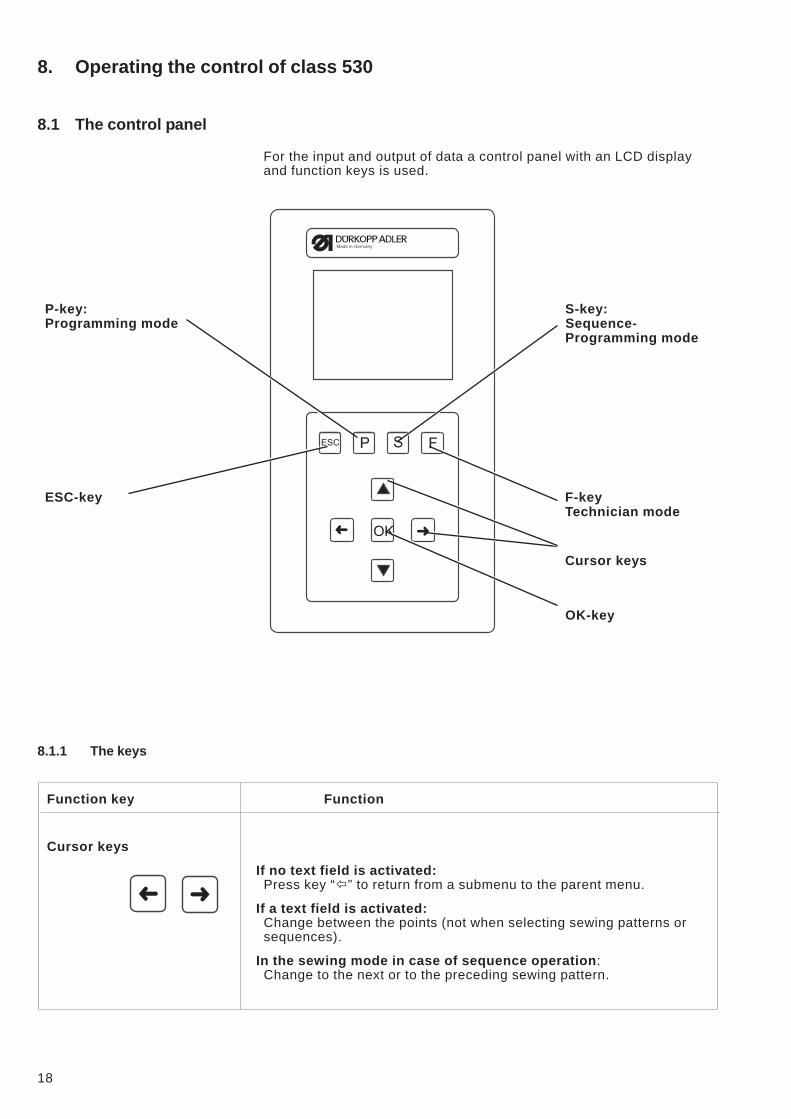
8. Operating the control of class 530
8.1 The control panel
For the input and output of data a control panel with an LCD display
and function keys is used.
P-key: S-key:
Programming mode Sequence-
Programming mode
ESC-key F-key
Technician mode
Cursor keys
OK-key
8.1.1 The keys
Function key Function
Cursor keys
If no text field is activated:
Press key “�” to return from a submenu to the parent menu.
If a text field is activated:
Change between the points (not when selecting sewing patterns or
sequences).
In the sewing mode in case of sequence operation:
Change to the next or to the preceding sewing pattern.
18
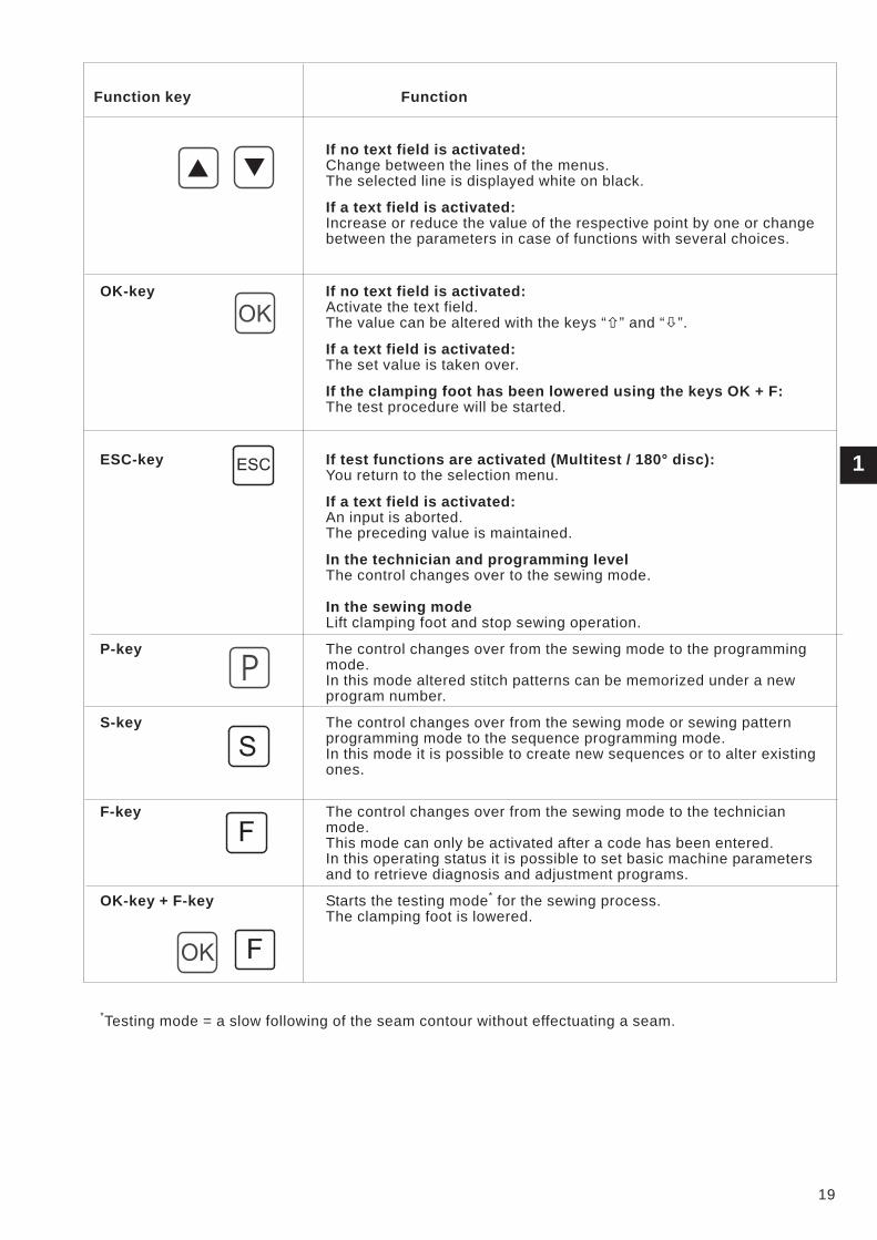
Function key Function
If no text field is activated:
Change between the lines of the menus.
The selected line is displayed white on black.
If a text field is activated:
Increase or reduce the value of the respective point by one or change
between the parameters in case of functions with several choices.
OK-key If no text field is activated:
Activate the text field.
The value can be altered with the keys “�” and “�”.
If a text field is activated:
The set value is taken over.
If the clamping foot has been lowered using the keys OK + F:
The test procedure will be started.
ESC-key If test functions are activated (Multitest / 180° disc):
You return to the selection menu.
If a text field is activated:
An input is aborted.
The preceding value is maintained.
In the technician and programming level
The control changes over to the sewing mode.
In the sewing mode
Lift clamping foot and stop sewing operation.
P-key The control changes over from the sewing mode to the programming
mode.
In this mode altered stitch patterns can be memorized under a new
program number.
S-key The control changes over from the sewing mode or sewing pattern
programming mode to the sequence programming mode.
In this mode it is possible to create new sequences or to alter existing
ones.
F-key The control changes over from the sewing mode to the technician
mode.
This mode can only be activated after a code has been entered.
In this operating status it is possible to set basic machine parameters
and to retrieve diagnosis and adjustment programs.
OK-key + F-key Starts the testing mode*
for the sewing process.
The clamping foot is lowered.
*Testing mode = a slow following of the seam contour without effectuating a seam.
1
19
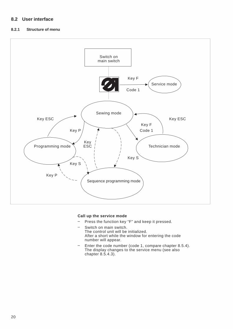
8.2 User interface
8.2.1 Structure of menu
Switch on
main switch
Key F
Service mode
Code 1
Sewing mode
Key ESC Key ESC
Key F
Key P Code 1
Key
Programming mode ESC Technician mode
Key S
Key S
Key P
Sequence programming mode
Call up the service mode
– Press the function key “F” and keep it pressed.
– Switch on main switch.
The control unit will be initialized.
After a short while the window for entering the code
number will appear.
– Enter the code number (code 1, compare chapter 8.5.4).
The display changes to the service menu (see also
chapter 8.5.4.3).
20
Call up the technician mode
– Switch on main switch.
The control is initialized.
The sewing mode menu appears on the display.
– Press key “ F ”.
– Enter Code 1 (see Chapter 8.5.4).
– Press key “OK” .
The display changes over to the technician mode.
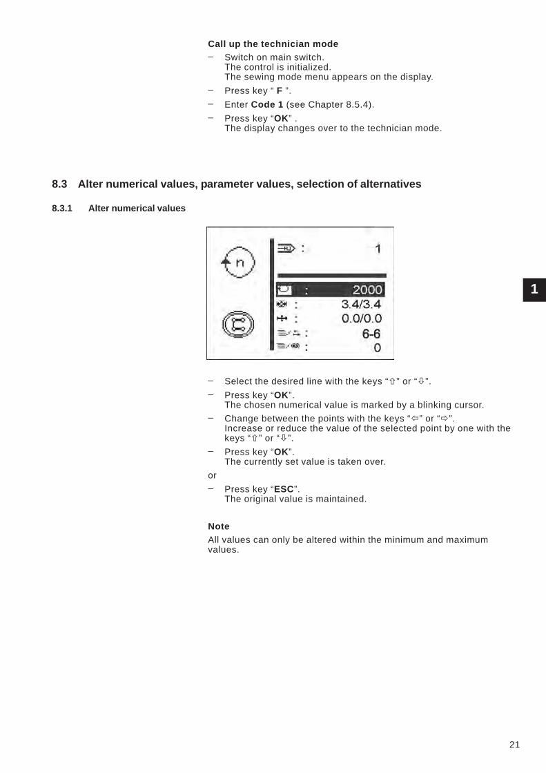
8.3 Alter numerical values, parameter values, selection of alternatives
8.3.1 Alter numerical values
– Select the desired line with the keys “�” or “�”.
– Press key “OK”.
The chosen numerical value is marked by a blinking cursor.
– Change between the points with the keys “�” or “�”.
Increase or reduce the value of the selected point by one with the
keys “�” or “�”.
– Press key “OK”.
The currently set value is taken over.
or
– Press key “ESC”.
The original value is maintained.
Note
All values can only be altered within the minimum and maximum
values.
1
21
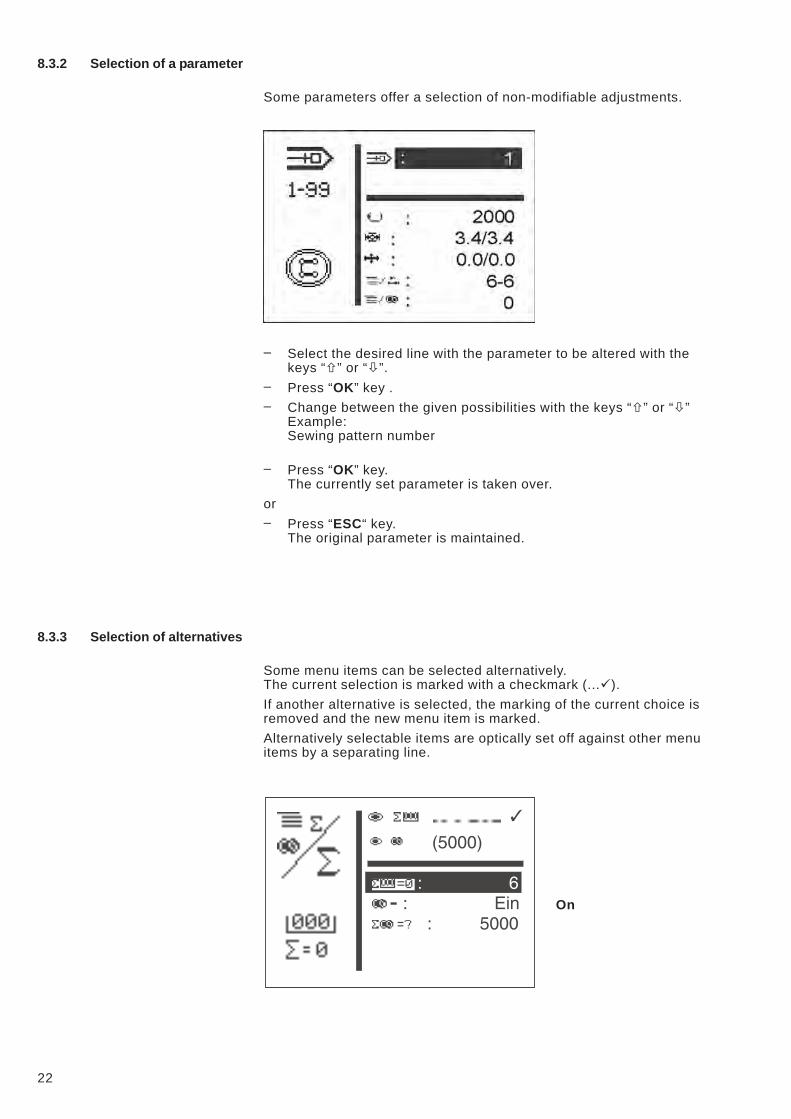
8.3.2 Selection of a parameter
Some parameters offer a selection of non-modifiable adjustments.
– Select the desired line with the parameter to be altered with the
keys “�” or “�”.
– Press “OK” key .
– Change between the given possibilities with the keys “�” or “�”
Example:
Sewing pattern number
– Press “OK” key.
The currently set parameter is taken over.
or
– Press “ESC“ key.
The original parameter is maintained.
8.3.3 Selection of alternatives
Some menu items can be selected alternatively.
The current selection is marked with a checkmark (...�).
If another alternative is selected, the marking of the current choice is
removed and the new menu item is marked.
Alternatively selectable items are optically set off against other menu
items by a separating line.
On
22
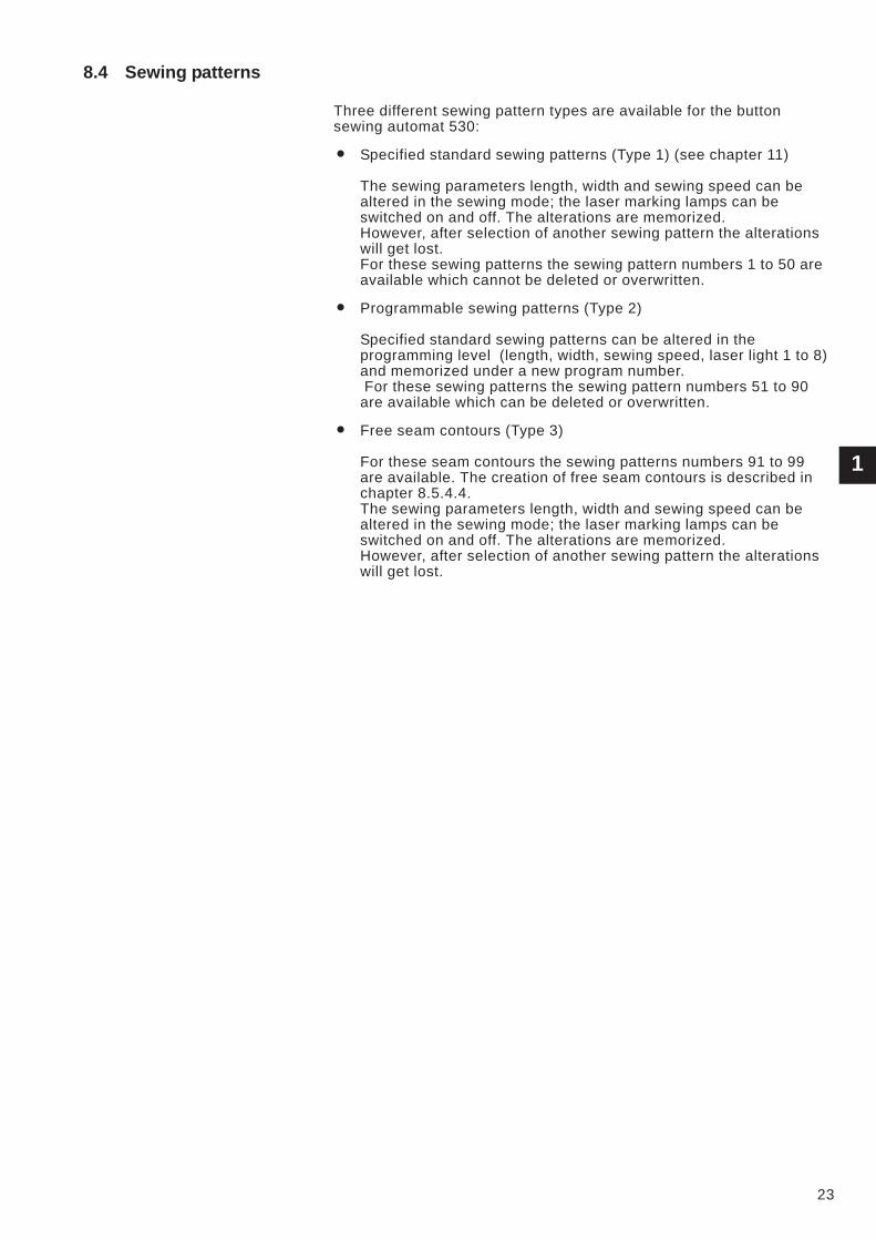
8.4 Sewing patterns
Three different sewing pattern types are available for the button
sewing automat 530:
� Specified standard sewing patterns (Type 1) (see chapter 11)
The sewing parameters length, width and sewing speed can be
altered in the sewing mode; the laser marking lamps can be
switched on and off. The alterations are memorized.
However, after selection of another sewing pattern the alterations
will get lost.
For these sewing patterns the sewing pattern numbers 1 to 50 are
available which cannot be deleted or overwritten.
� Programmable sewing patterns (Type 2)
Specified standard sewing patterns can be altered in the
programming level (length, width, sewing speed, laser light 1 to 8)
and memorized under a new program number.
For these sewing patterns the sewing pattern numbers 51 to 90
are available which can be deleted or overwritten.
� Free seam contours (Type 3)
For these seam contours the sewing patterns numbers 91 to 99
are available. The creation of free seam contours is described in
chapter 8.5.4.4.
The sewing parameters length, width and sewing speed can be
altered in the sewing mode; the laser marking lamps can be
switched on and off. The alterations are memorized.
However, after selection of another sewing pattern the alterations
will get lost.
1
23
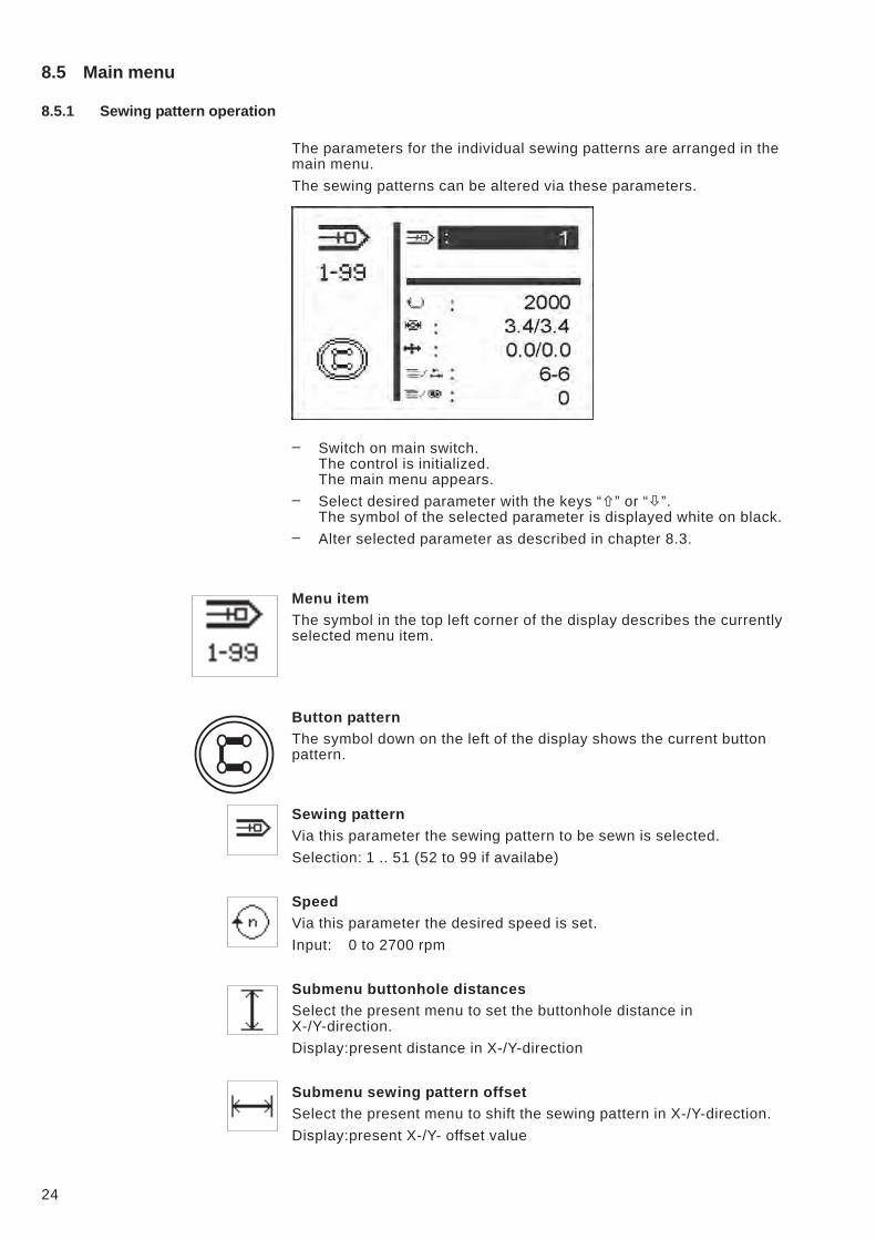
8.5 Main menu
8.5.1 Sewing pattern operation
The parameters for the individual sewing patterns are arranged in the
main menu.
The sewing patterns can be altered via these parameters.
– Switch on main switch.
The control is initialized.
The main menu appears.
– Select desired parameter with the keys “�” or “�”.
The symbol of the selected parameter is displayed white on black.
– Alter selected parameter as described in chapter 8.3.
Menu item
The symbol in the top left corner of the display describes the currently
selected menu item.
Button pattern
The symbol down on the left of the display shows the current button
pattern.
Sewing pattern
Via this parameter the sewing pattern to be sewn is selected.
Selection: 1 .. 51 (52 to 99 if availabe)
Speed
Via this parameter the desired speed is set.
Input: 0 to 2700 rpm
Submenu buttonhole distances
Select the present menu to set the buttonhole distance in
X-/Y-direction.
Display:present distance in X-/Y-direction
Submenu sewing pattern offset
Select the present menu to shift the sewing pattern in X-/Y-direction.
Display:present X-/Y- offset value
24
Submenu
Behind this symbol there is a submenu.
Number of stitches
By this menu line, the needle throw distribution for standard sewing
patterns will be indicated and the complete number of stitches for free
contours (cannot be modified).
When selecting the line with key “OK” the submenu “Special functions”
opens.
Counter reading
Via this menu line the following counters can be read:
Counter of daily number of pieces
or
Counter of capacity
When selecting the line with key “OK” the submenu “Counter of daily
number of pieces/Counter of capacity” is opened.
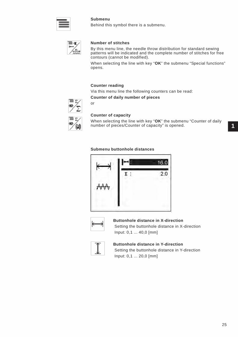
Submenu buttonhole distances
Buttonhole distance in X-direction
Setting the buttonhole distance in X-direction
Input: 0,1 ... 40,0 [mm]
Buttonhole distance in Y-direction
Setting the buttonhole distance in Y-direction
Input: 0,1 ... 20,0 [mm]
1
25
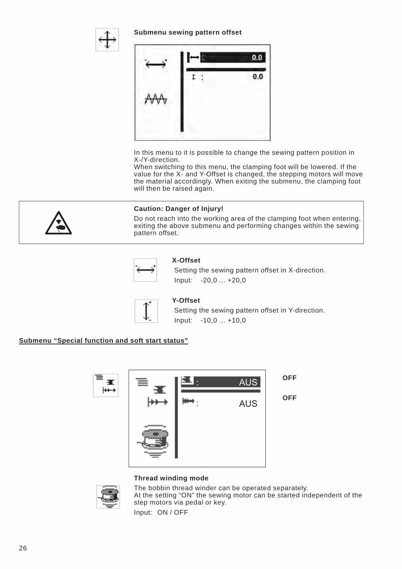
Submenu sewing pattern offset
In this menu to it is possible to change the sewing pattern position in
X-/Y-direction.
When switching to this menu, the clamping foot will be lowered. If the
value for the X- and Y-Offset is changed, the stepping motors will move
the material accordingly. When exiting the submenu, the clamping foot
will then be raised again.
Caution: Danger of Injury!
Do not reach into the working area of the clamping foot when entering,
exiting the above submenu and performing changes within the sewing
pattern offset.
X-Offset
Setting the sewing pattern offset in X-direction.
Input: -20,0 ... +20,0
Y-Offset
Setting the sewing pattern offset in Y-direction.
Input: -10,0 ... +10,0
Submenu “Special function and soft start status”
OFF
OFF
Thread winding mode
The bobbin thread winder can be operated separately.
At the setting “ON” the sewing motor can be started independent of the
step motors via pedal or key.
Input: ON / OFF
26
Winding thread on to a bobbin:
With pedal
– Step pedal forwards (step 2).
The sewing motor starts.
– Step pedal backwards.
The sewing motor stops.
Via control panel BF3
– Press “F” key .
The sewing motor starts.
– Press “ESC” key.
The sewing motor stops.
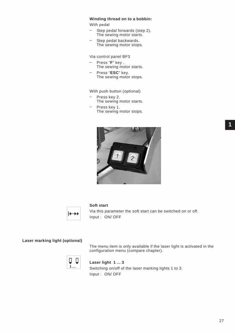
With push button (optional)
– Press key 2.
The sewing motor starts.
– Press key 1.
The sewing motor stops.
Soft start
Via this parameter the soft start can be switched on or off.
Input : ON/ OFF
Laser marking light (optional)
The menu item is only available if the laser light is activated in the
configuration menu (compare chapter).
Laser light 1 ... 3
Switching on/off of the laser marking lights 1 to 3.
Input : ON/ OFF
1
27
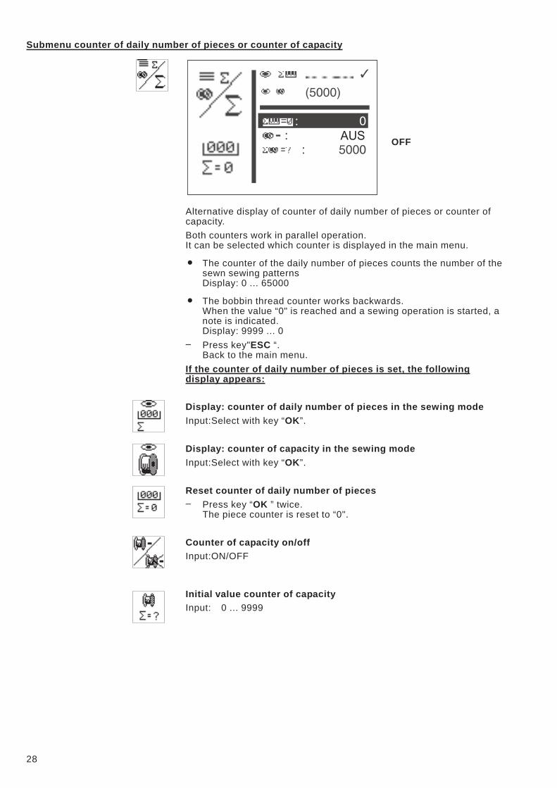
Submenu counter of daily number of pieces or counter of capacity
OFF
Alternative display of counter of daily number of pieces or counter of
capacity.
Both counters work in parallel operation.
It can be selected which counter is displayed in the main menu.
� The counter of the daily number of pieces counts the number of the
sewn sewing patterns
Display: 0 ... 65000
� The bobbin thread counter works backwards.
When the value “0" is reached and a sewing operation is started, a
note is indicated.
Display: 9999 ... 0
– Press key"ESC “.
Back to the main menu.
If the counter of daily number of pieces is set, the following
display appears:
Display: counter of daily number of pieces in the sewing mode
Input:Select with key “OK”.
Display: counter of capacity in the sewing mode
Input:Select with key “OK”.
Reset counter of daily number of pieces
– Press key “OK ” twice.
The piece counter is reset to “0".
Counter of capacity on/off
Input:ON/OFF
Initial value counter of capacity
Input: 0 ... 9999
28
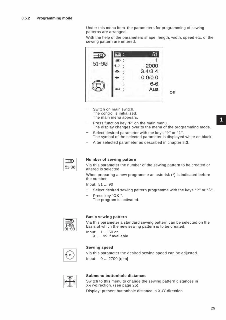
8.5.2 Programming mode
Under this menu item the parameters for programming of sewing
patterns are arranged.
With the help of the parameters shape, length, width, speed etc. of the
sewing pattern are entered.
Off
– Switch on main switch.
The control is initialized.
The main menu appears.
– Press function key “P” on the main menu.
The display changes over to the menu of the programming mode.
– Select desired parameter with the keys “�” or “�”.
The symbol of the selected parameter is displayed white on black.
– Alter selected parameter as described in chapter 8.3.
Number of sewing pattern
Via this parameter the number of the sewing pattern to be created or
altered is selected.
When preparing a new programme an asterisk (*) is indicated before
the number.
Input: 51 ... 90
– Select desired sewing pattern programme with the keys “�” or “�”.
– Press key “OK ”.
The program is activated.
Basic sewing pattern
Via this parameter a standard sewing pattern can be selected on the
basis of which the new sewing pattern is to be created.
Input: 1 ... 50 or
91 ... 99 if available
Sewing speed
Via this parameter the desired sewing speed can be adjusted.
Input: 0 ... 2700 [rpm]
Submenu buttonhole distances
Switch to this menu to change the sewing pattern distances in
X-/Y-direction. (see page 25).
Display: present buttonhole distance in X-/Y-direction
1
29
Submenu sewing pattern offset
Select the present menu to shift the sewing pattern in X-/Y-direction.
Display:present X-/Y- offset value
Number of stitches and stitch distribution
Only indication of needle throw distribution (for standard patterns) or of
the complete number of stitches (for free contours).
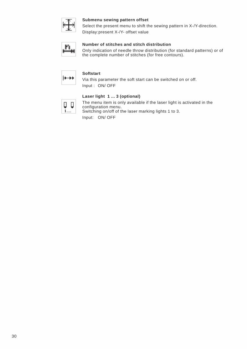
Softstart
Via this parameter the soft start can be switched on or off.
Input : ON/ OFF
Laser light 1 ... 3 (optional)
The menu item is only available if the laser light is activated in the
configuration menu.
Switching on/off of the laser marking lights 1 to 3.
Input: ON/ OFF
30
8.5.3 Sewing pattern sequence
8.5.3.1 Switching the sequence programming mode on/off
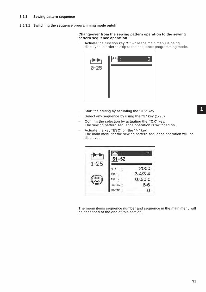
Changeover from the sewing pattern operation to the sewing
pattern sequence operation
– Actuate the function key “S” while the main menu is being
displayed in order to skip to the sequence programming mode.
– Start the editing by actuating the “OK” key
– Select any sequence by using the “�“ key (1-25)
– Confirm the selection by actuating the “OK” key.
The sewing pattern sequence operation is switched on.
– Actuate the key “ESC” or the “�“ key.
The main menu for the sewing pattern sequence operation will be
displayed.
The menu items sequence number and sequence in the main menu will
be described at the end of this section.
1
31
0
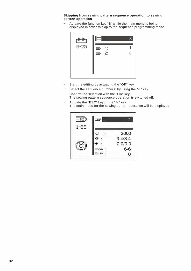
Skipping from sewing pattern sequence operation to sewing
pattern operation
– Actuate the function key “S” while the main menu is being
displayed in order to skip to the sequence programming mode.
– Start the editing by actuating the “OK” key.
– Select the sequence number 0 by using the “�“ key.
– Confirm the selection with the “OK” key.
The sewing pattern sequence operation is switched off.
– Actuate the “ESC” key or the “�” key.
The main menu for the sewing pattern operation will be displayed.
32
3
1
0
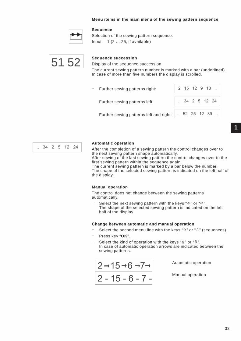
Menu items in the main menu of the sewing pattern sequence
Sequence
Selection of the sewing pattern sequence.
Input: 1 (2 … 25, if available)
Sequence succession
Display of the sequence succession.
The current sewing pattern number is marked with a bar (underlined).
In case of more than five numbers the display is scrolled.
– Further sewing patterns right:
Further sewing patterns left:
Further sewing patterns left and right:
Automatic operation
After the completion of a sewing pattern the control changes over to
the next sewing pattern shape automatically.
After sewing of the last sewing pattern the control changes over to the
first sewing pattern within the sequence again.
The current sewing pattern is marked by a bar below the number.
The shape of the selected sewing pattern is indicated on the left half of
the display.
Manual operation
The control does not change between the sewing patterns
automatically.
– Select the next sewing pattern with the keys “�” or “�”.
The shape of the selected sewing pattern is indicated on the left
half of the display.
Change between automatic and manual operation
– Select the second menu line with the keys “�” or “�” (sequences) .
– Press key “OK”.
– Select the kind of operation with the keys “�” or “�”.
In case of automatic operation arrows are indicated between the
sewing patterns.
Automatic operation
Manual operation
1
33
51 52
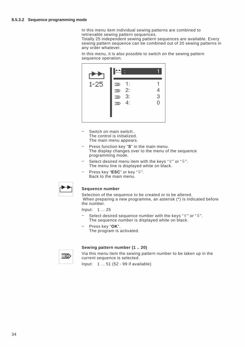
8.5.3.2 Sequence programming mode
In this menu item individual sewing patterns are combined to
retrievable sewing pattern sequences.
Totally 25 independent sewing pattern sequences are available. Every
sewing pattern sequence can be combined out of 20 sewing patterns in
any order whatever.
In this menu, it is also possible to switch on the sewing pattern
sequence operation.
– Switch on main switch..
The control is initialized.
The main menu appears.
– Press function key “S” in the main menu.
The display changes over to the menu of the sequence
programming mode.
– Select desired menu item with the keys “�” or “�”.
The menu line is displayed white on black.
– Press key “ESC” or key “�”.
Back to the main menu.
Sequence number
Selection of the sequence to be created or to be altered.
When preparing a new programme, an asterisk (*) is indicated before
the number.
Input: 1 ... 25
– Select desired sequence number with the keys “�” or “�”.
The sequence number is displayed white on black.
– Press key “OK”.
The program is activated.
Sewing pattern number (1 .. 20)
Via this menu item the sewing pattern number to be taken up in the
current sequence is selected.
Input: 1 ... 51 (52 - 99 if available)
34
8.5.4 Technician mode
In the technician mode the following menus are included:
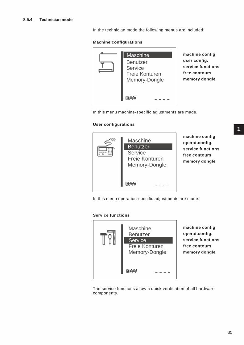
Machine configurations
machine config
user config.
service functions
free contours
memory dongle
In this menu machine-specific adjustments are made.
User configurations
machine config
operat.config.
service functions
free contours
memory dongle
In this menu operation-specific adjustments are made.
Service functions
machine config
operat.config.
service functions
free contours
memory dongle
The service functions allow a quick verification of all hardware
components.
1
35
Benutzer
Service
Freie Konturen
Memory-Dongle
Maschine
Maschine
Service
Freie Konturen
Memory-Dongle
Benutzer
Maschine
Freie Konturen
Memory-Dongle
Benutzer
Service
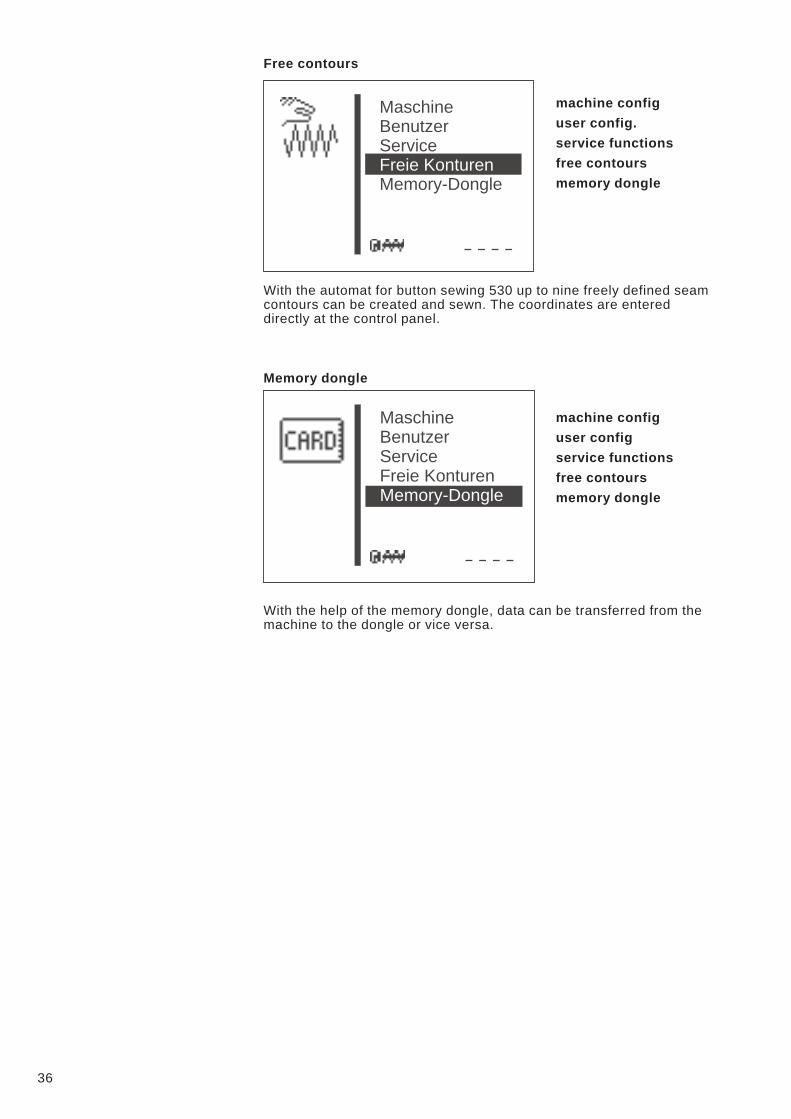
Free contours
machine config
user config.
service functions
free contours
memory dongle
With the automat for button sewing 530 up to nine freely defined seam
contours can be created and sewn. The coordinates are entered
directly at the control panel.
Memory dongle
machine config
user config
service functions
free contours
memory dongle
With the help of the memory dongle, data can be transferred from the
machine to the dongle or vice versa.
36
Maschine
Memory-Dongle
Benutzer
Service
Freie Konturen
Maschine
Benutzer
Service
Freie Konturen
Memory-Dongle
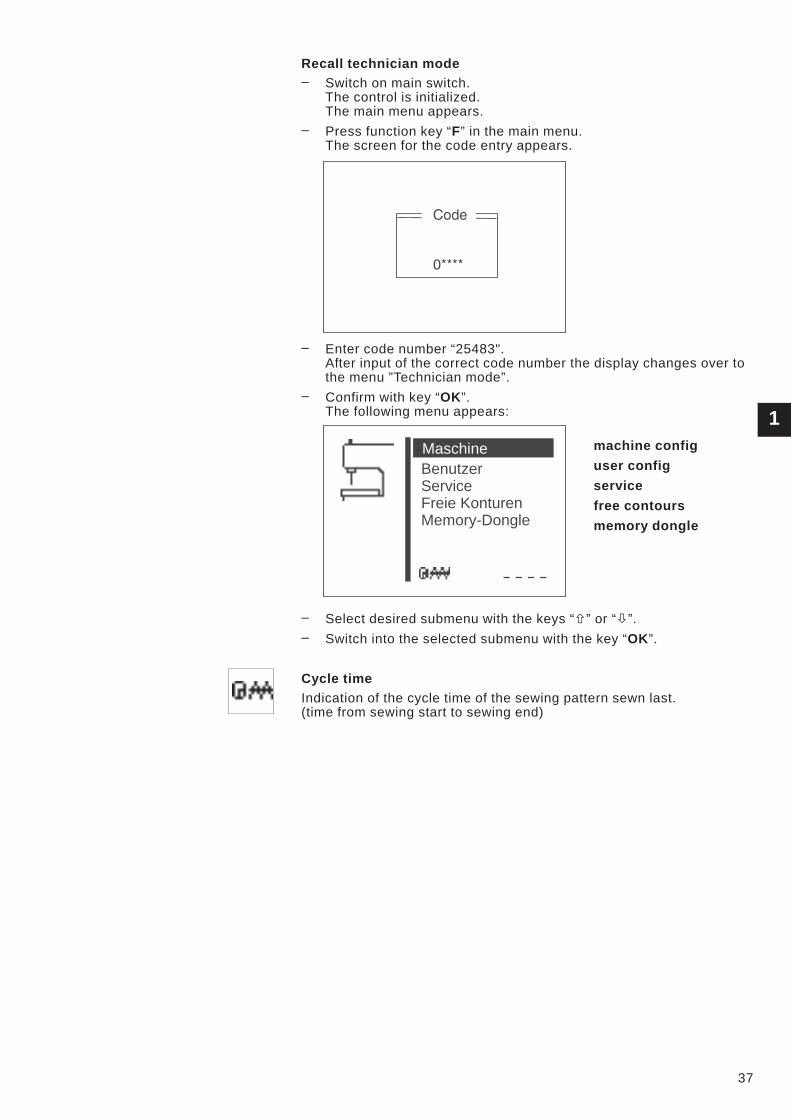
Recall technician mode
– Switch on main switch.
The control is initialized.
The main menu appears.
– Press function key “F” in the main menu.
The screen for the code entry appears.
– Enter code number “25483".
After input of the correct code number the display changes over to
the menu ”Technician mode”.
– Confirm with key “OK”.
The following menu appears:
machine config
user config
service
free contours
memory dongle
– Select desired submenu with the keys “�” or “�”.
– Switch into the selected submenu with the key “OK”.
Cycle time
Indication of the cycle time of the sewing pattern sewn last.
(time from sewing start to sewing end)
1
37
Benutzer
Service
Freie Konturen
Memory-Dongle
Maschine
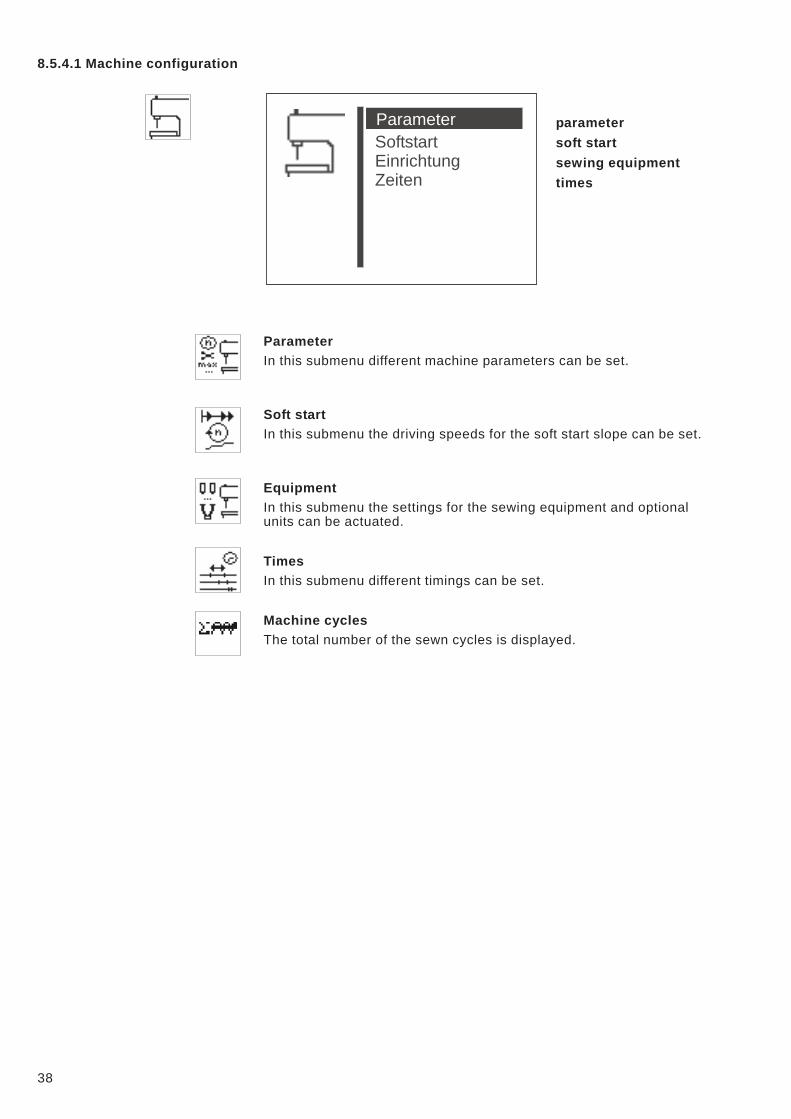
8.5.4.1 Machine configuration
parameter
soft start
sewing equipment
times
Parameter
In this submenu different machine parameters can be set.
Soft start
In this submenu the driving speeds for the soft start slope can be set.
Equipment
In this submenu the settings for the sewing equipment and optional
units can be actuated.
Times
In this submenu different timings can be set.
Machine cycles
The total number of the sewn cycles is displayed.
38
Softstart
Einrichtung
Zeiten
Parameter
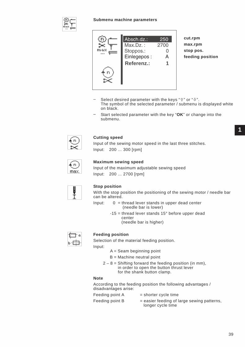
Submenu machine parameters
cut.rpm
max.rpm
stop pos.
feeding position
– Select desired parameter with the keys “�” or “�”.
The symbol of the selected parameter / submenu is displayed white
on black.
– Start selected parameter with the key “OK” or change into the
submenu.
Cutting speed
Input of the sewing motor speed in the last three stitches.
Input: 200 … 300 [rpm]
Maximum sewing speed
Input of the maximum adjustable sewing speed
Input: 200 … 2700 [rpm]
Stop position
With the stop position the positioning of the sewing motor / needle bar
can be altered.
Input: 0 = thread lever stands in upper dead center
(needle bar is lower)
-15 = thread lever stands 15° before upper dead
center
(needle bar is higher)
Feeding position
Selection of the material feeding position.
Input:
A = Seam beginning point
B = Machine neutral point
2 – 8 = Shifting forward the feeding position (in mm),
in order to open the button thrust lever
for the shank button clamp.
Note
According to the feeding position the following advantages /
disadvantages arise:
Feeding point A = shorter cycle time
Feeding point B = easier feeding of large sewing patterns,
longer cycle time
1
39
Referenz.: 1
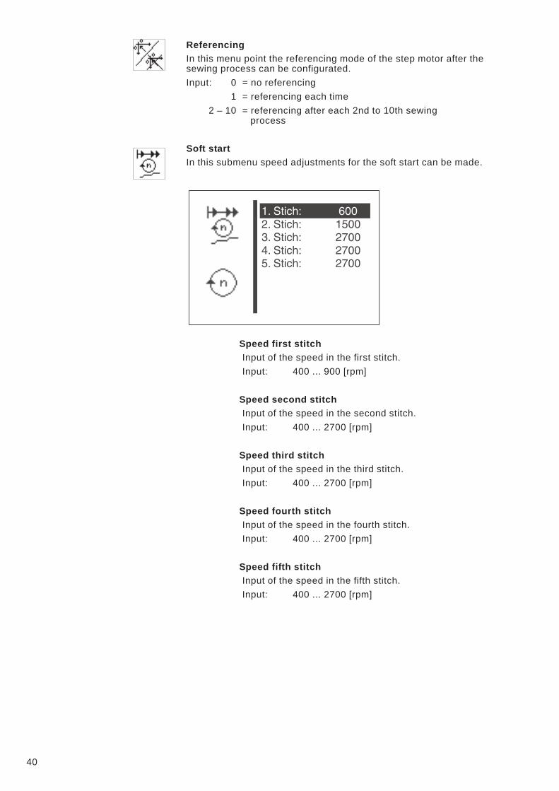
Referencing
In this menu point the referencing mode of the step motor after the
sewing process can be configurated.
Input: 0 = no referencing
1 = referencing each time
2 – 10 = referencing after each 2nd to 10th sewing
process
Soft start
In this submenu speed adjustments for the soft start can be made.
Speed first stitch
Input of the speed in the first stitch.
Input: 400 ... 900 [rpm]
Speed second stitch
Input of the speed in the second stitch.
Input: 400 ... 2700 [rpm]
Speed third stitch
Input of the speed in the third stitch.
Input: 400 ... 2700 [rpm]
Speed fourth stitch
Input of the speed in the fourth stitch.
Input: 400 ... 2700 [rpm]
Speed fifth stitch
Input of the speed in the fifth stitch.
Input: 400 ... 2700 [rpm]
40
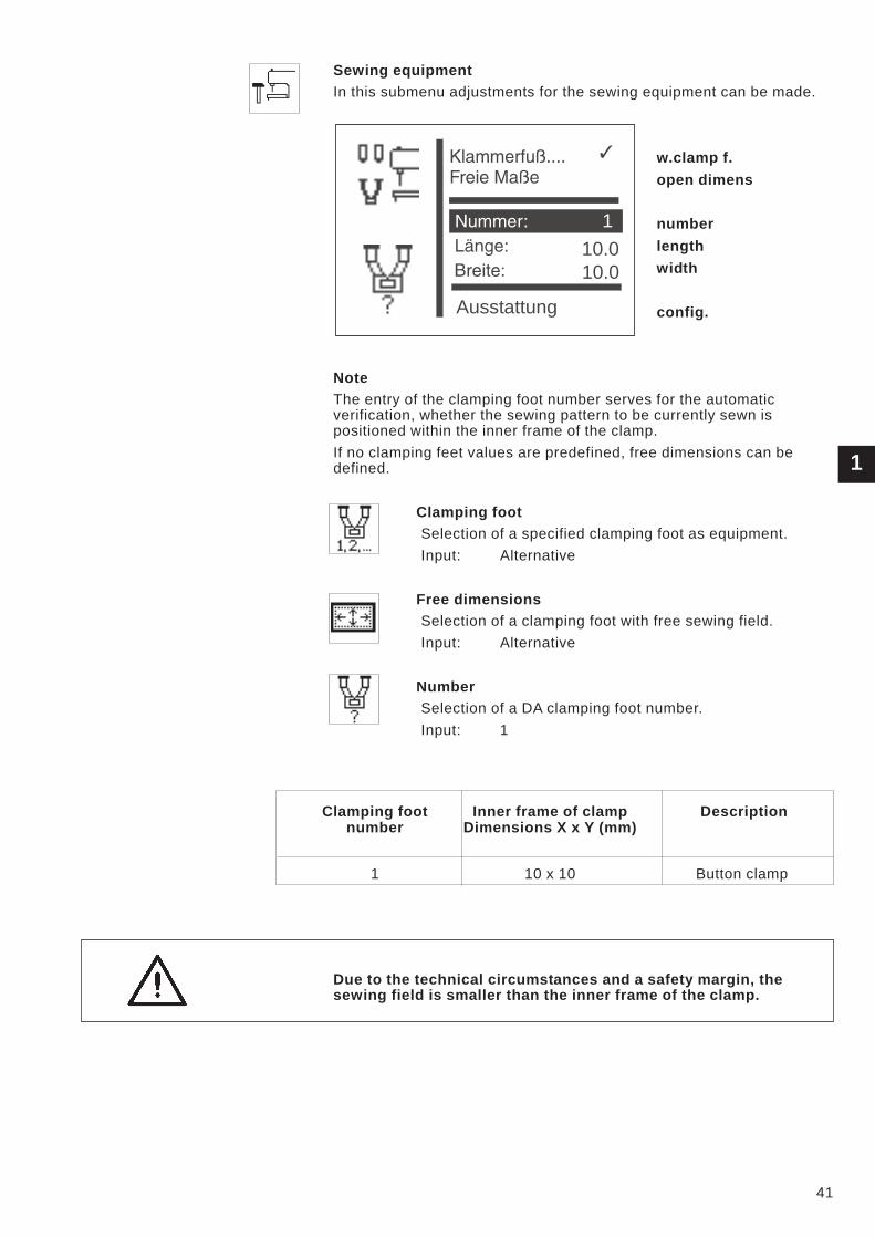
Sewing equipment
In this submenu adjustments for the sewing equipment can be made.
w.clamp f.
open dimens
number
length
width
config.
Note
The entry of the clamping foot number serves for the automatic
verification, whether the sewing pattern to be currently sewn is
positioned within the inner frame of the clamp.
If no clamping feet values are predefined, free dimensions can be
defined.
Clamping foot
Selection of a specified clamping foot as equipment.
Input: Alternative
Free dimensions
Selection of a clamping foot with free sewing field.
Input: Alternative
Number
Selection of a DA clamping foot number.
Input: 1
Clamping foot Inner frame of clamp Description
number Dimensions X x Y (mm)
1 10 x 10 Button clamp
Due to the technical circumstances and a safety margin, the
sewing field is smaller than the inner frame of the clamp.
1
41
10.0
10.0
Ausstattung
1
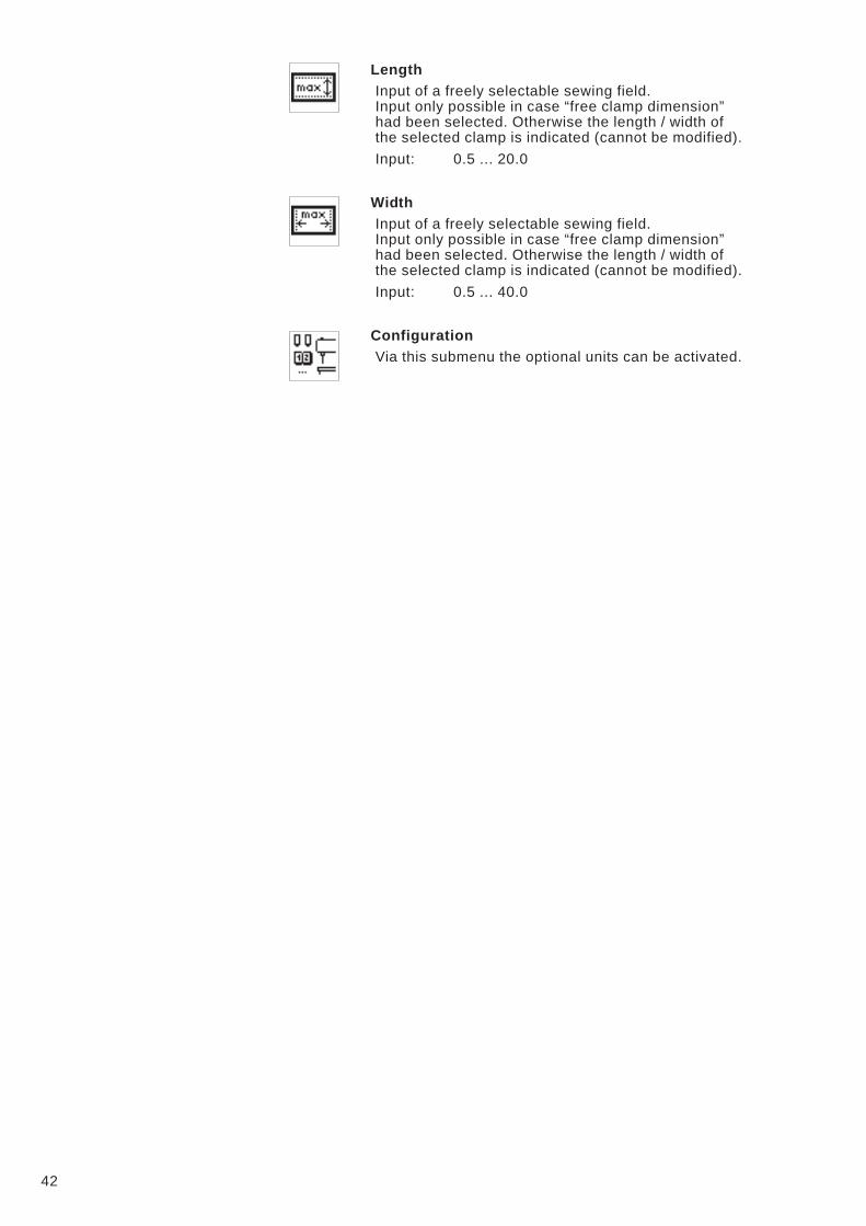
Length
Input of a freely selectable sewing field.
Input only possible in case “free clamp dimension”
had been selected. Otherwise the length / width of
the selected clamp is indicated (cannot be modified).
Input: 0.5 ... 20.0
Width
Input of a freely selectable sewing field.
Input only possible in case “free clamp dimension”
had been selected. Otherwise the length / width of
the selected clamp is indicated (cannot be modified).
Input: 0.5 ... 40.0
Configuration
Via this submenu the optional units can be activated.
42

Submenu Configuration
hand switch:off
laser light: off
opt. sign.
assignment input
assignment output
Hand switch
Activating of optional hand switches. When the option is switched on, a
menu item in order to select the operation mode will appear in the
menu “User configuration”.
Input:ON/OFF
Laser lights
Activating the 3 optional laser lights.
Input:ON/OFF
Optical signalling
Via this submenu an indication of error and event messages and of the
message “hook thread is zero” can be configurated and activated via
two 24V-outputs.
Optical signalling
Activating of the indication. Beforehand outputs 1 and 2
must be configurated, otherwise this menu item cannot be
selected.
Input: ON/OFF
Output 1
Selection of the output for error and event messages.
Input: 1 ...8 (if 24V-outputs are vacant)
Output 2
Selection of the output for the message “hook thread is
zero”
Input: 1 ...8 (if 24V-outputs are vacant)
Assignment of the inputs
This menu item gives on overall view of the assignment of the inputs
with (optional) units.
Assignment of the 24V-outputs
This menu item gives an overall view of the assignment of the
24V-outputs with optional units.
43
1
Handtast.: Aus
Laserl.: Aus
Opt. Anzeige
Belegung Eing.
Belegung Ausg.
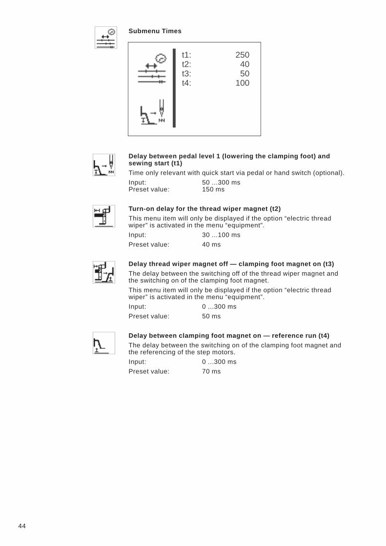
Submenu Times
Delay between pedal level 1 (lowering the clamping foot) and
sewing start (t1)
Time only relevant with quick start via pedal or hand switch (optional).
Input: 50 ...300 ms
Preset value: 150 ms
Turn-on delay for the thread wiper magnet (t2)
This menu item will only be displayed if the option “electric thread
wiper” is activated in the menu “equipment”.
Input: 30 ...100 ms
Preset value: 40 ms
Delay thread wiper magnet off — clamping foot magnet on (t3)
The delay between the switching off of the thread wiper magnet and
the switching on of the clamping foot magnet.
This menu item will only be displayed if the option “electric thread
wiper” is activated in the menu “equipment”.
Input: 0 ...300 ms
Preset value: 50 ms
Delay between clamping foot magnet on — reference run (t4)
The delay between the switching on of the clamping foot magnet and
the referencing of the step motors.
Input: 0 ...300 ms
Preset value: 70 ms
44
t1: 250
t2: 40
t3: 50
t4: 100

8.5.4.2 User configuration
In this menu operation-specific adjustments are made.
language
sewing mode
manual keys
param.mod
forced st
pattern locking
sequence locking
– Select desired parameter/ submenu with the keys “�” or “�”.
The selected parameter/ submenu is displayed white on black.
– Start selected parameter with the key “OK” or change into the
submenu.
Language
In this submenu the language can be chosen.
German
Selection of the German language for the technician level.
English
Selection of the English language for the technician level.
Parameter
Selection of the numbering of menu items for the
technicial level (see chapter 13).
1
45
Sprache
Par. sperr.: AUS
Nähm. sperren
Sequ. sperren
Deutsch . . . . . .
English
Parameter
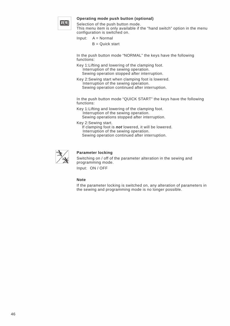
Operating mode push button (optional)
Selection of the push button mode.
This menu item is only available if the “hand switch” option in the menu
configuration is switched on.
Input: A = Normal
B = Quick start
In the push button mode “NORMAL” the keys have the following
functions:
Key 1:Lifting and lowering of the clamping foot.
Interruption of the sewing operation.
Sewing operation stopped after interruption.
Key 2:Sewing start when clamping foot is lowered.
Interruption of the sewing operation.
Sewing operation continued after interruption.
In the push button mode “QUICK START” the keys have the following
functions:
Key 1:Lifting and lowering of the clamping foot.
Interruption of the sewing operation.
Sewing operations stopped after interruption.
Key 2:Sewing start.
If clamping foot is not lowered, it will be lowered.
Interruption of the sewing operation.
Sewing operation continued after interruption.
Parameter locking
Switching on / off of the parameter alteration in the sewing and
programming mode.
Input: ON / OFF
Note
If the parameter locking is switched on, any alteration of parameters in
the sewing and programming mode is no longer possible.
46
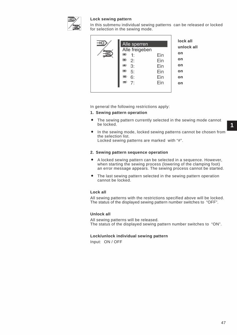
Lock sewing pattern
In this submenu individual sewing patterns can be released or locked
for selection in the sewing mode.
lock all
unlock all
on
on
on
on
on
on
In general the following restrictions apply:
1. Sewing pattern operation
� The sewing pattern currently selected in the sewing mode cannot
be locked.
� In the sewing mode, locked sewing patterns cannot be chosen from
the selection list.
Locked sewing patterns are marked with “#”.
2. Sewing pattern sequence operation
� A locked sewing pattern can be selected in a sequence. However,
when starting the sewing process (lowering of the clamping foot)
an error message appears. The sewing process cannot be started.
� The last sewing pattern selected in the sewing pattern operation
cannot be locked.
Lock all
All sewing patterns with the restrictions specified above will be locked.
The status of the displayed sewing pattern number switches to “OFF”.
Unlock all
All sewing patterns will be released.
The status of the displayed sewing pattern number switches to “ON”.
Lock/unlock individual sewing pattern
Input: ON / OFF
1
47
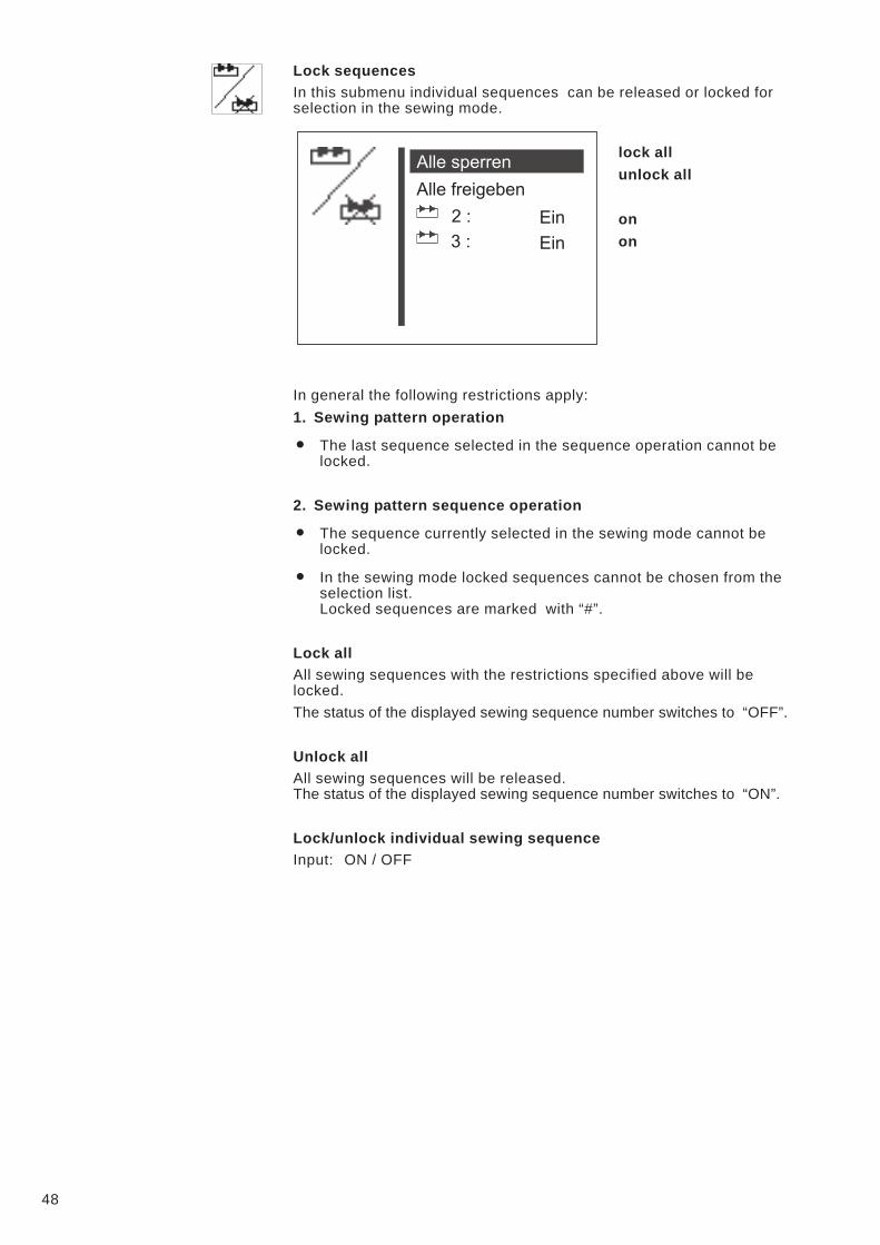
Lock sequences
In this submenu individual sequences can be released or locked for
selection in the sewing mode.
lock all
unlock all
on
on
In general the following restrictions apply:
1. Sewing pattern operation
� The last sequence selected in the sequence operation cannot be
locked.
2. Sewing pattern sequence operation
� The sequence currently selected in the sewing mode cannot be
locked.
� In the sewing mode locked sequences cannot be chosen from the
selection list.
Locked sequences are marked with “#”.
Lock all
All sewing sequences with the restrictions specified above will be
locked.
The status of the displayed sewing sequence number switches to “OFF”.
Unlock all
All sewing sequences will be released.
The status of the displayed sewing sequence number switches to “ON”.
Lock/unlock individual sewing sequence
Input: ON / OFF
48
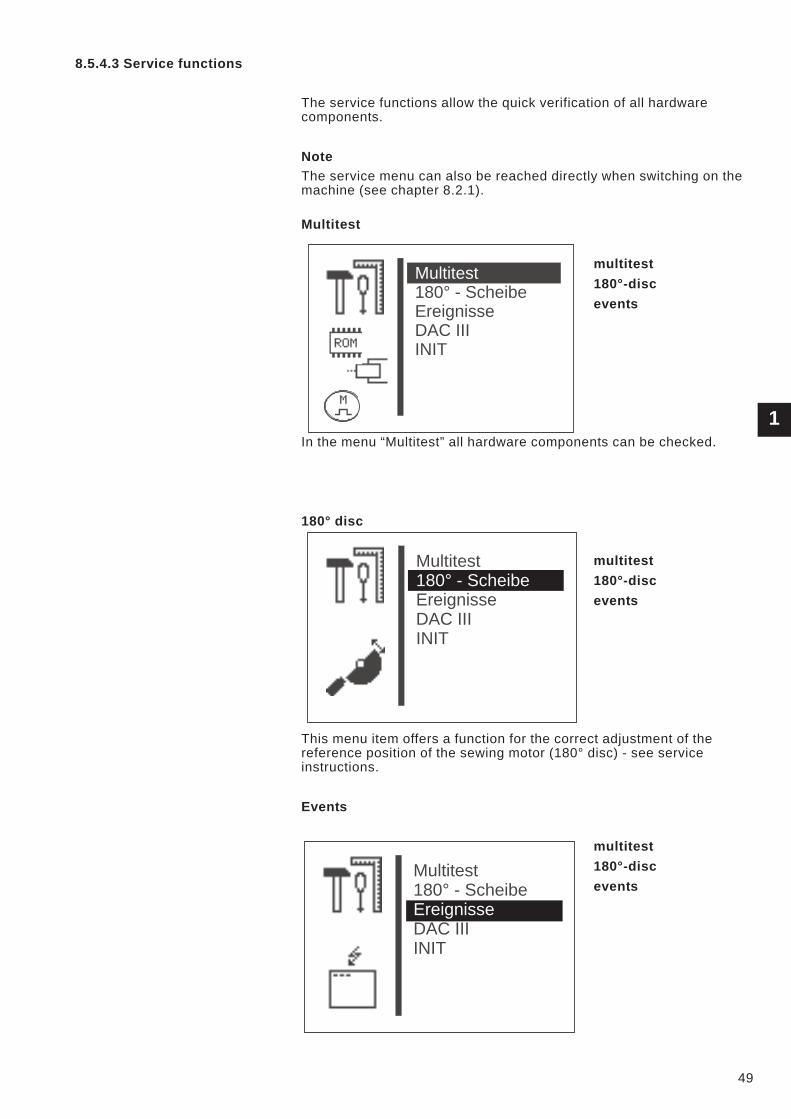
8.5.4.3 Service functions
The service functions allow the quick verification of all hardware
components.
Note
The service menu can also be reached directly when switching on the
machine (see chapter 8.2.1).
Multitest
multitest
180°-disc
events
In the menu “Multitest” all hardware components can be checked.
180° disc
multitest
180°-disc
events
This menu item offers a function for the correct adjustment of the
reference position of the sewing motor (180° disc) - see service
instructions.
Events
multitest
180°-disc
events
1
49
Multitest
180° - Scheibe
Ereignisse
DAC III
INIT
Multitest
DAC III
INIT
180° - Scheibe
Ereignisse
Multitest
180° - Scheibe
DAC III
INIT
Ereignisse
DAC III
multitest
180°-disc
events
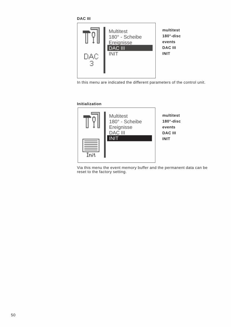
DAC III
INIT
In this menu are indicated the different parameters of the control unit.
Initialization
multitest
180°-disc
events
DAC III
INIT
Via this menu the event memory buffer and the permanent data can be
reset to the factory setting.
50
Multitest
180° - Scheibe
Ereignisse
INIT
DAC III
Multitest
DAC III
180° - Scheibe
Ereignisse
INIT

Multitest
Selection of the submenu of Multitest
output test
PWM-output test
input test
auto input tst
motor test
step.motor tst
RAM test
EEPROM test
Caution: Danger of injury !
Do not reach into the running machine during the function test of the
output elements.
Danger of Breakage!
Check before the testing of single output elements, whether the
machine mouvements can cause collisions.
1
51
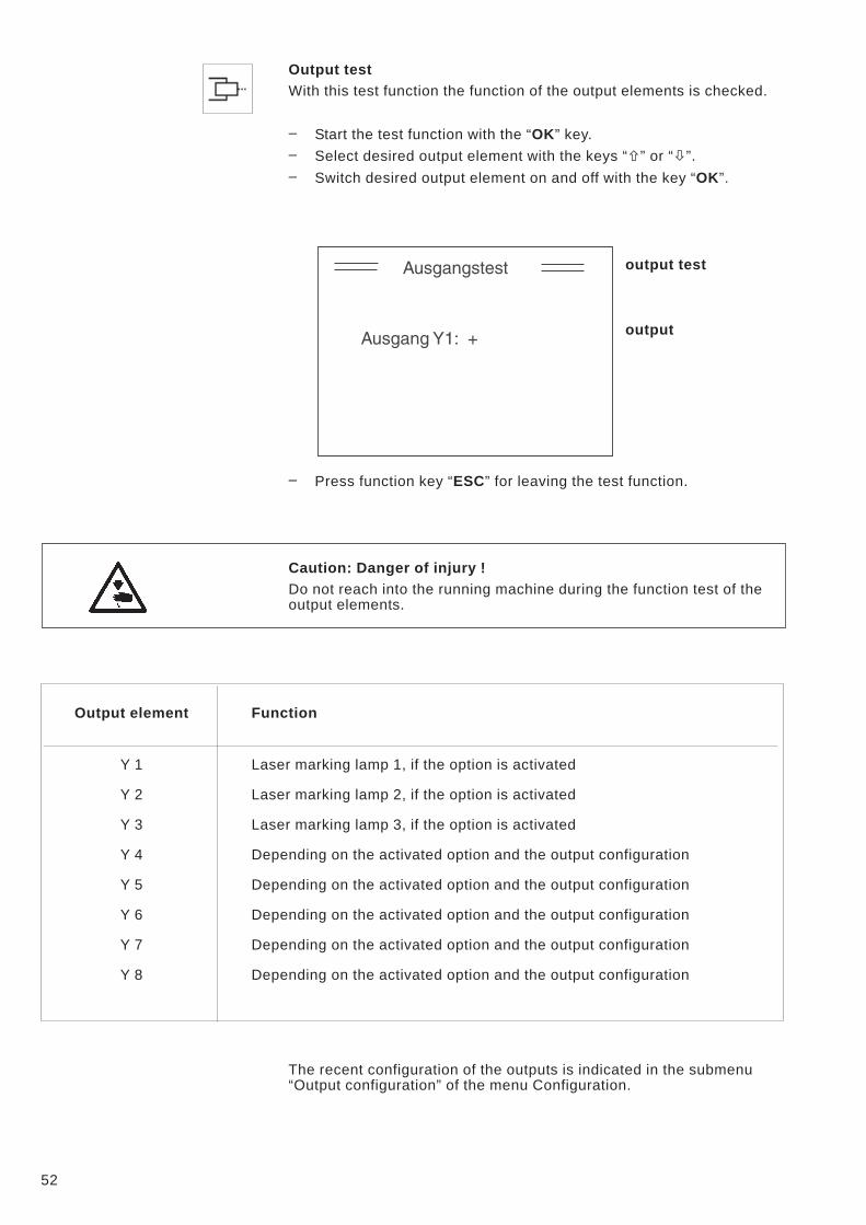
Output test
With this test function the function of the output elements is checked.
– Start the test function with the “OK” key.
– Select desired output element with the keys “�” or “�”.
– Switch desired output element on and off with the key “OK”.
output test
output
– Press function key “ESC” for leaving the test function.
Caution: Danger of injury !
Do not reach into the running machine during the function test of the
output elements.
Output element Function
Y 1 Laser marking lamp 1, if the option is activated
Y 2 Laser marking lamp 2, if the option is activated
Y 3 Laser marking lamp 3, if the option is activated
Y 4 Depending on the activated option and the output configuration
Y 5 Depending on the activated option and the output configuration
Y 6 Depending on the activated option and the output configuration
Y 7 Depending on the activated option and the output configuration
Y 8 Depending on the activated option and the output configuration
The recent configuration of the outputs is indicated in the submenu
“Output configuration” of the menu Configuration.
52
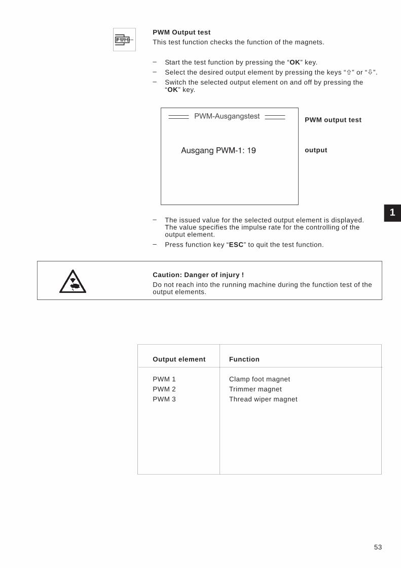
PWM Output test
This test function checks the function of the magnets.
– Start the test function by pressing the “OK” key.
– Select the desired output element by pressing the keys “�” or “�”.
– Switch the selected output element on and off by pressing the
“OK” key.
PWM output test
output
– The issued value for the selected output element is displayed.
The value specifies the impulse rate for the controlling of the
output element.
– Press function key “ESC” to quit the test function.
Caution: Danger of injury !
Do not reach into the running machine during the function test of the
output elements.
Output element Function
PWM 1 Clamp foot magnet
PWM 2 Trimmer magnet
PWM 3 Thread wiper magnet
53
1
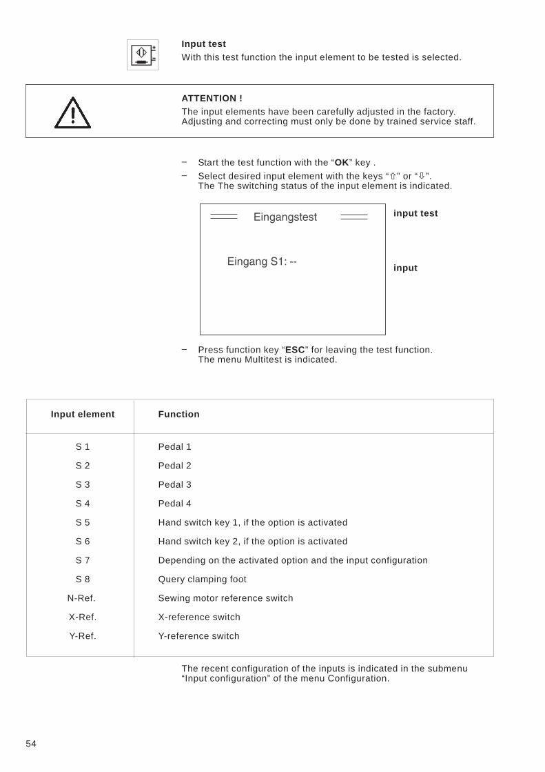
Input test
With this test function the input element to be tested is selected.
ATTENTION !
The input elements have been carefully adjusted in the factory.
Adjusting and correcting must only be done by trained service staff.
– Start the test function with the “OK” key .
– Select desired input element with the keys “�” or “�”.
The The switching status of the input element is indicated.
input test
input
– Press function key “ESC” for leaving the test function.
The menu Multitest is indicated.
Input element Function
S 1 Pedal 1
S 2 Pedal 2
S 3 Pedal 3
S 4 Pedal 4
S 5 Hand switch key 1, if the option is activated
S 6 Hand switch key 2, if the option is activated
S 7 Depending on the activated option and the input configuration
S 8 Query clamping foot
N-Ref. Sewing motor reference switch
X-Ref. X-reference switch
Y-Ref. Y-reference switch
The recent configuration of the inputs is indicated in the submenu
“Input configuration” of the menu Configuration.
54

Auto-Input test
With this test function the function of the input elements is checked.
– Start test function with the “OK” key.
– Actuate desired input element.
The switch status and the number of the actuated input element
are indicated.
auto-input test
– Press the function key “ESC” for leaving the test function.
The menu Multitest is indicated.
Input element Function
S 1 Pedal 1
S 2 Pedal 2
S 3 Pedal 3
S 4 Pedal 4
S 5 Hand switch key 1, if the option is activated
S 6 Hand switch key 2, if the option is activated
S 7 Depending on the activated option and the input configuration
S 8 Query clamping foot
N-Ref. Sewing motor reference switch
X-Ref. X-reference switch
Y-Ref. Y-reference switch
The recent configuration of the inputs is indicated in the submenu
“Input configuration” of the menu Configuration.
1
55
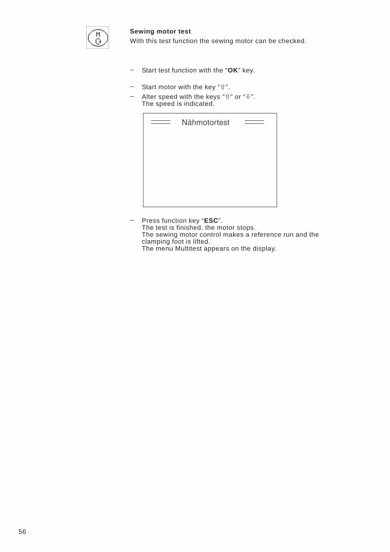
Sewing motor test
With this test function the sewing motor can be checked.
– Start test function with the “OK” key.
– Start motor with the key “�”.
– Alter speed with the keys “�” or “�”.
The speed is indicated.
– Press function key “ESC”.
The test is finished, the motor stops.
The sewing motor control makes a reference run and the
clamping foot is lifted.
The menu Multitest appears on the display.
56
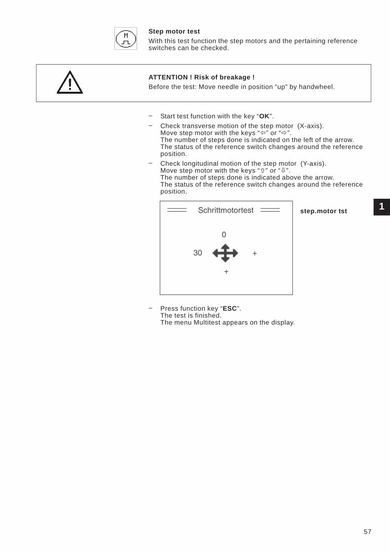
Step motor test
With this test function the step motors and the pertaining reference
switches can be checked.
ATTENTION ! Risk of breakage !
Before the test: Move needle in position “up” by handwheel.
– Start test function with the key “OK”.
– Check transverse motion of the step motor (X-axis).
Move step motor with the keys “�” or “�”.
The number of steps done is indicated on the left of the arrow.
The status of the reference switch changes around the reference
position.
– Check longitudinal motion of the step motor (Y-axis).
Move step motor with the keys “�” or “�”.
The number of steps done is indicated above the arrow.
The status of the reference switch changes around the reference
position.
step.motor tst
– Press function key “ESC”.
The test is finished.
The menu Multitest appears on the display.
1
57
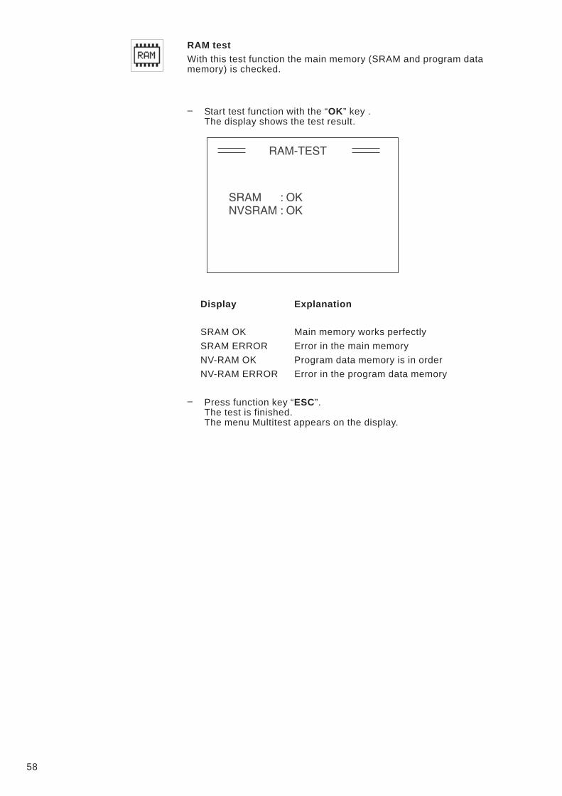
RAM test
With this test function the main memory (SRAM and program data
memory) is checked.
– Start test function with the “OK” key .
The display shows the test result.
Display Explanation
SRAM OK Main memory works perfectly
SRAM ERROR Error in the main memory
NV-RAM OK Program data memory is in order
NV-RAM ERROR Error in the program data memory
– Press function key “ESC”.
The test is finished.
The menu Multitest appears on the display.
58
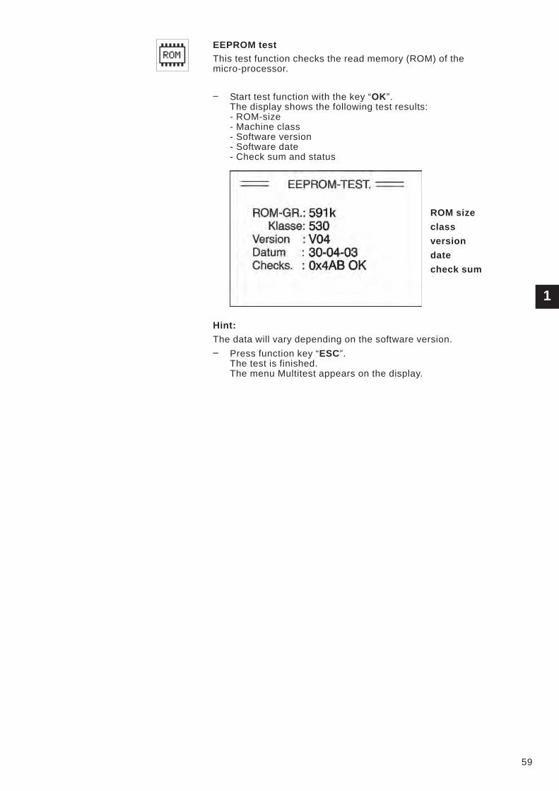
EEPROM test
This test function checks the read memory (ROM) of the
micro-processor.
– Start test function with the key “OK”.
The display shows the following test results:
- ROM-size
- Machine class
- Software version
- Software date
- Check sum and status
ROM size
class
version
date
check sum
Hint:
The data will vary depending on the software version.
– Press function key “ESC”.
The test is finished.
The menu Multitest appears on the display.
1
59
60
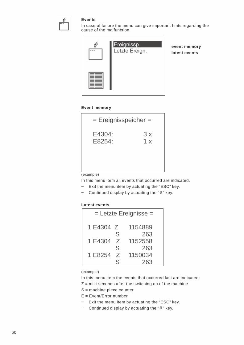
Events
In case of failure the menu can give important hints regarding the
cause of the malfunction.
event memory
latest events
Event memory
(example)
In this menu item all events that occurred are indicated.
– Exit the menu item by actuating the “ESC” key.
– Continued display by actuating the “�” key.
Latest events
(example)
In this menu item the events that occurred last are indicated:
Z = milli-seconds after the switching on of the machine
S = machine piece counter
E = Event/Error number
– Exit the menu item by actuating the “ESC” key.
– Continued display by actuating the “�” key.
= Ereignisspeicher =
E4304: 3 x
E8254: 1 x
= Letzte Ereignisse =
1 E4304 Z 1154889
S 263
1 E4304 Z 1152558
S 263
1 E8254 Z 1150034
S 263
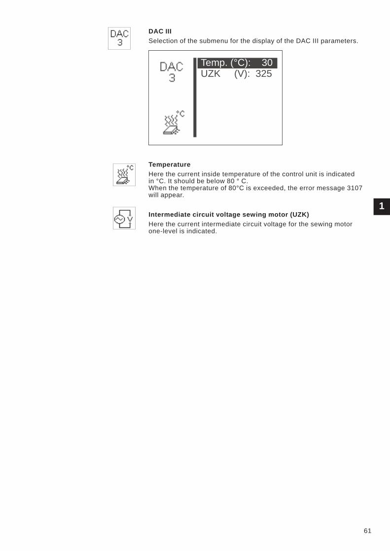
DAC III
Selection of the submenu for the display of the DAC III parameters.
Temperature
Here the current inside temperature of the control unit is indicated
in °C. It should be below 80 ° C.
When the temperature of 80°C is exceeded, the error message 3107
will appear.
Intermediate circuit voltage sewing motor (UZK)
Here the current intermediate circuit voltage for the sewing motor
one-level is indicated.
1
61
Temp. (°C): 30
UZK (V): 325
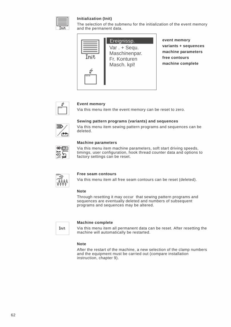
Initialization (Init)
The selection of the submenu for the initialization of the event memory
and the permanent data.
event memory
variants + sequences
machine parameters
free contours
machine complete
Event memory
Via this menu item the event memory can be reset to zero.
Sewing pattern programs (variants) and sequences
Via this menu item sewing pattern programs and sequences can be
deleted.
Machine parameters
Via this menu item machine parameters, soft start driving speeds,
timings, user configuration, hook thread counter data and options to
factory settings can be reset.
Free seam contours
Via this menu item all free seam contours can be reset (deleted).
Note
Through resetting it may occur that sewing pattern programs and
sequences are eventually deleted and numbers of subsequent
programs and sequences may be altered.
Machine complete
Via this menu item all permanent data can be reset. After resetting the
machine will automatically be restarted.
Note
After the restart of the machine, a new selection of the clamp numbers
and the equipment must be carried out (compare installation
instruction, chapter 9).
62
Var . + Sequ.
Maschinenpar.
Fr. Konturen
Masch. kpl!
Ereignissp.
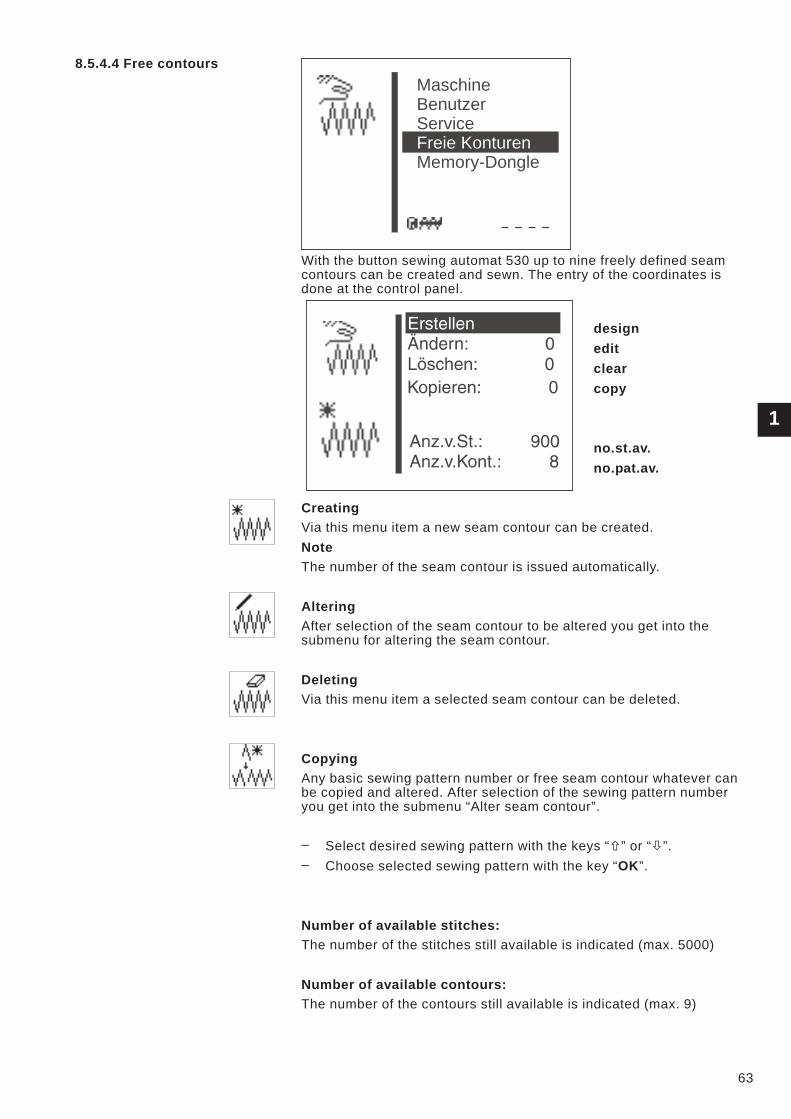
8.5.4.4 Free contours
With the button sewing automat 530 up to nine freely defined seam
contours can be created and sewn. The entry of the coordinates is
done at the control panel.
design
edit
clear
copy
no.st.av.
no.pat.av.
Creating
Via this menu item a new seam contour can be created.
Note
The number of the seam contour is issued automatically.
Altering
After selection of the seam contour to be altered you get into the
submenu for altering the seam contour.
Deleting
Via this menu item a selected seam contour can be deleted.
Copying
Any basic sewing pattern number or free seam contour whatever can
be copied and altered. After selection of the sewing pattern number
you get into the submenu “Alter seam contour”.
– Select desired sewing pattern with the keys “�” or “�”.
– Choose selected sewing pattern with the key “OK”.
Number of available stitches:
The number of the stitches still available is indicated (max. 5000)
Number of available contours:
The number of the contours still available is indicated (max. 9)
1
63
Maschine
Memory-Dongle
Benutzer
Service
Freie Konturen
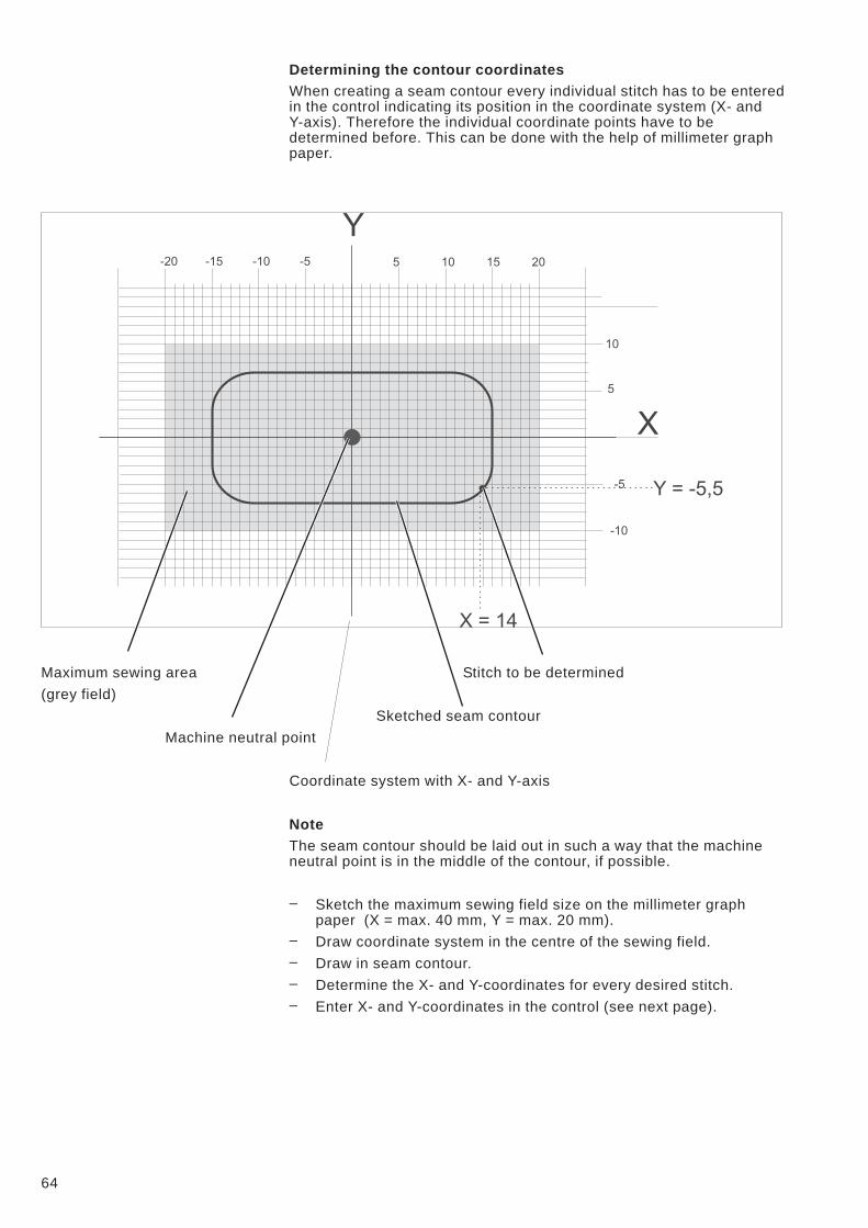
Determining the contour coordinates
When creating a seam contour every individual stitch has to be entered
in the control indicating its position in the coordinate system (X- and
Y-axis). Therefore the individual coordinate points have to be
determined before. This can be done with the help of millimeter graph
paper.
Maximum sewing area Stitch to be determined
(grey field)
Sketched seam contour
Machine neutral point
Coordinate system with X- and Y-axis
Note
The seam contour should be laid out in such a way that the machine
neutral point is in the middle of the contour, if possible.
– Sketch the maximum sewing field size on the millimeter graph
paper (X = max. 40 mm, Y = max. 20 mm).
– Draw coordinate system in the centre of the sewing field.
– Draw in seam contour.
– Determine the X- and Y-coordinates for every desired stitch.
– Enter X- and Y-coordinates in the control (see next page).
64
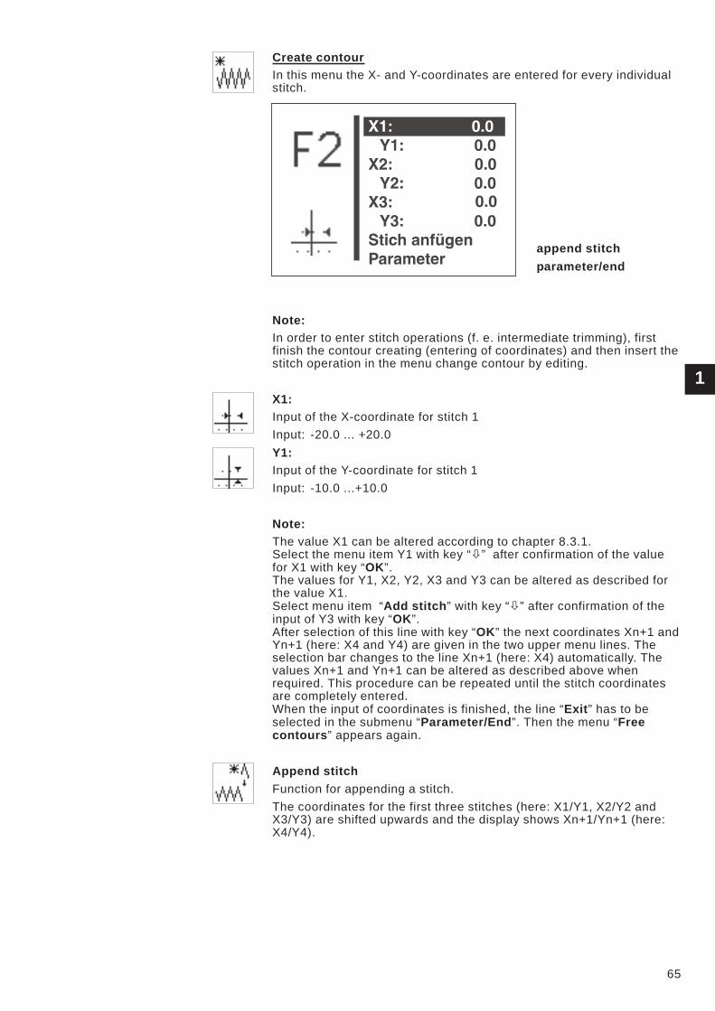
Create contour
In this menu the X- and Y-coordinates are entered for every individual
stitch.
append stitch
parameter/end
Note:
In order to enter stitch operations (f. e. intermediate trimming), first
finish the contour creating (entering of coordinates) and then insert the
stitch operation in the menu change contour by editing.
X1:
Input of the X-coordinate for stitch 1
Input: -20.0 ... +20.0
Y1:
Input of the Y-coordinate for stitch 1
Input: -10.0 ...+10.0
Note:
The value X1 can be altered according to chapter 8.3.1.
Select the menu item Y1 with key “�” after confirmation of the value
for X1 with key “OK”.
The values for Y1, X2, Y2, X3 and Y3 can be altered as described for
the value X1.
Select menu item “Add stitch” with key “�” after confirmation of the
input of Y3 with key “OK”.
After selection of this line with key “OK” the next coordinates Xn+1 and
Yn+1 (here: X4 and Y4) are given in the two upper menu lines. The
selection bar changes to the line Xn+1 (here: X4) automatically. The
values Xn+1 and Yn+1 can be altered as described above when
required. This procedure can be repeated until the stitch coordinates
are completely entered.
When the input of coordinates is finished, the line “Exit” has to be
selected in the submenu “Parameter/End”. Then the menu “Free
contours” appears again.
Append stitch
Function for appending a stitch.
The coordinates for the first three stitches (here: X1/Y1, X2/Y2 and
X3/Y3) are shifted upwards and the display shows Xn+1/Yn+1 (here:
X4/Y4).
1
65
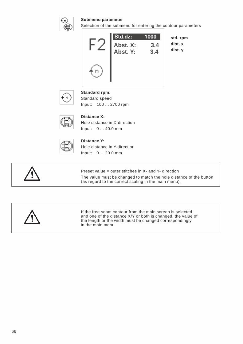
Submenu parameter
Selection of the submenu for entering the contour parameters
std. rpm
dist. x
dist. y
Standard rpm:
Standard speed
Input: 100 ... 2700 rpm
Distance X:
Hole distance in X-direction
Input: 0 ... 40.0 mm
Distance Y:
Hole distance in Y-direction
Input: 0 ... 20.0 mm
Preset value = outer stitches in X- and Y- direction
The value must be changed to match the hole distance of the button
(as regard to the correct scaling in the main menu).
If the free seam contour from the main screen is selected
and one of the distance X/Y or both is changed, the value of
the length or the width must be changed correspondingly
in the main menu.
66
Abst. X: 3.4
Abst. Y: 3.4
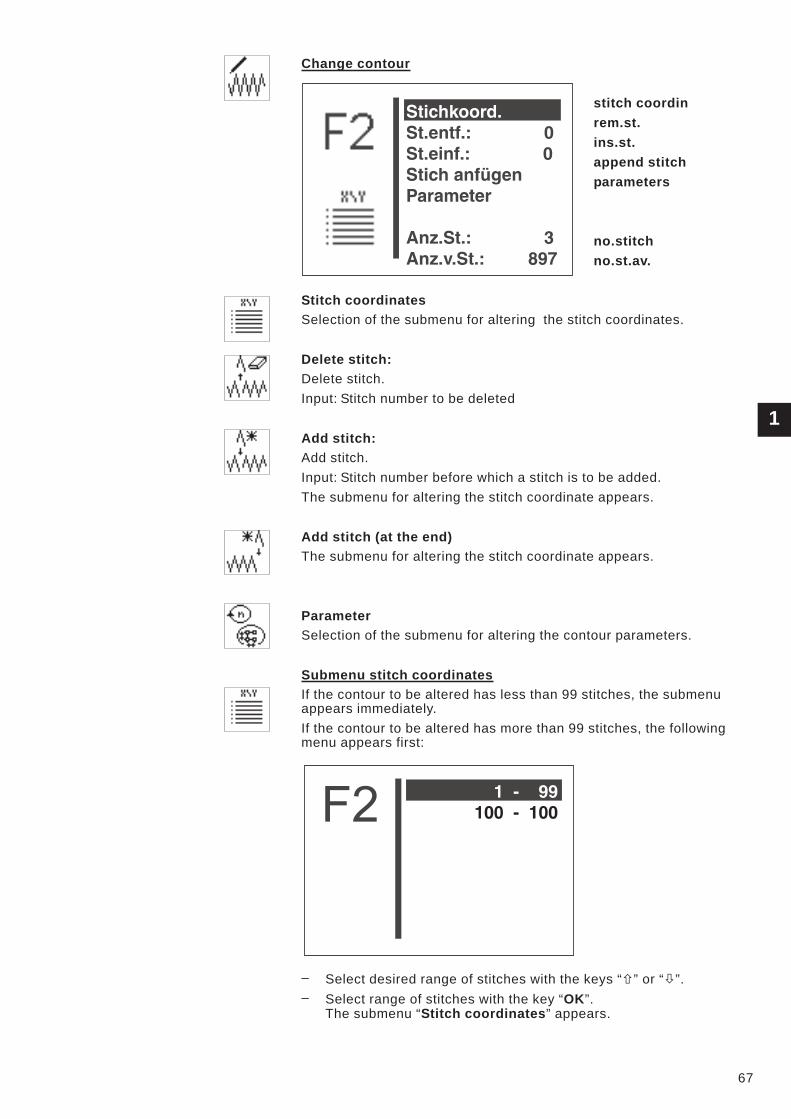
Change contour
stitch coordin
rem.st.
ins.st.
append stitch
parameters
no.stitch
no.st.av.
Stitch coordinates
Selection of the submenu for altering the stitch coordinates.
Delete stitch:
Delete stitch.
Input: Stitch number to be deleted
Add stitch:
Add stitch.
Input: Stitch number before which a stitch is to be added.
The submenu for altering the stitch coordinate appears.
Add stitch (at the end)
The submenu for altering the stitch coordinate appears.
Parameter
Selection of the submenu for altering the contour parameters.
Submenu stitch coordinates
If the contour to be altered has less than 99 stitches, the submenu
appears immediately.
If the contour to be altered has more than 99 stitches, the following
menu appears first:
– Select desired range of stitches with the keys “�” or “�”.
– Select range of stitches with the key “OK”.
The submenu “Stitch coordinates” appears.
1
67

– Select desired stitch with the keys “�” or “�”.
– Select stitch with the key “OK”.
The submenu for altering a stitch coordinate appears.
If a stitch operation is classed with a stitch, this will be marked with an
asterisk (*) instead of a diagonal stroke (/) on the display.
Submenu “Alter stitch coordinate”
This submenu appears when selecting a stitch coordinate from the
menu “Stitch coordinates” and after adding or altering a stitch.
Example
X10
Altering of the X-coordinate for stitch 10
Input: -20.0 ... +20.0
Y10
Altering of the Y-coordinate for stitch 10
Input: -10.0 ... +10.0
OP10
Altering of the stitch operation for stitch 10
Input: 0 ... 1 (compare to the opposite table)
Hint:
The stitch operation entered will be executed after the stitch.
68
X10: 0.0
Y10: 0.0
Op10: 1
1-
99
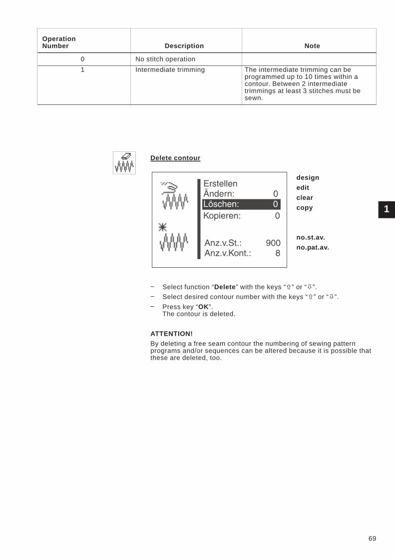
Operation
Number Description Note
0 No stitch operation
1 Intermediate trimming The intermediate trimming can be
programmed up to 10 times within a
contour. Between 2 intermediate
trimmings at least 3 stitches must be
sewn.
Delete contour
design
edit
clear
copy
no.st.av.
no.pat.av.
– Select function “Delete” with the keys “�” or “�”.
– Select desired contour number with the keys “�” or “�”.
– Press key “OK”.
The contour is deleted.
ATTENTION!
By deleting a free seam contour the numbering of sewing pattern
programs and/or sequences can be altered because it is possible that
these are deleted, too.
1
69

Copy contour
– Select the menu item “copy“ with the “�“ or “�“ keys.
– Actuate the “OK” key.
– Select the desired sewing pattern number (1-50,91-99) with
the “�“ or “�“ keys.
– Confirm the selection by actuating the “OK” key.
The contour will be copied and the menu “Change contour” will be
displayed.
In order to change the contour, please follow the instructions of the
paragraph “Change contour” on page number 67.
70
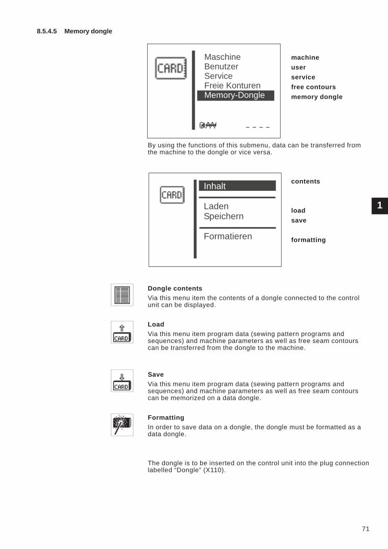
8.5.4.5 Memory dongle
machine
user
service
free contours
memory dongle
By using the functions of this submenu, data can be transferred from
the machine to the dongle or vice versa.
contents
load
save
formatting
Dongle contents
Via this menu item the contents of a dongle connected to the control
unit can be displayed.
Load
Via this menu item program data (sewing pattern programs and
sequences) and machine parameters as well as free seam contours
can be transferred from the dongle to the machine.
Save
Via this menu item program data (sewing pattern programs and
sequences) and machine parameters as well as free seam contours
can be memorized on a data dongle.
Formatting
In order to save data on a dongle, the dongle must be formatted as a
data dongle.
The dongle is to be inserted on the control unit into the plug connection
labelled “Dongle” (X110).
1
71
Maschine
Benutzer
Service
Freie Konturen
Memory-Dongle
Inhalt
Laden
Speichern
Formatieren
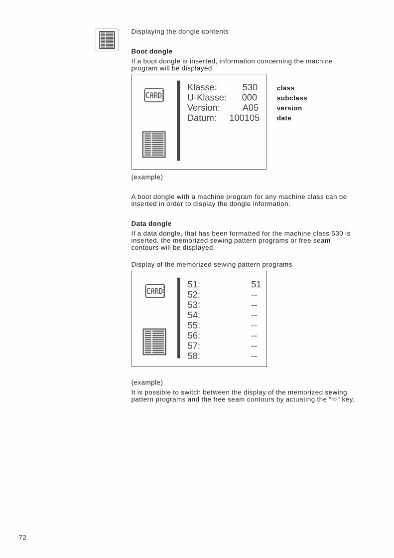
Displaying the dongle contents
Boot dongle
If a boot dongle is inserted, information concerning the machine
program will be displayed.
class
subclass
version
date
(example)
A boot dongle with a machine program for any machine class can be
inserted in order to display the dongle information.
Data dongle
If a data dongle, that has been formatted for the machine class 530 is
inserted, the memorized sewing pattern programs or free seam
contours will be displayed.
Display of the memorized sewing pattern programs
(example)
It is possible to switch between the display of the memorized sewing
pattern programs and the free seam contours by actuating the “�“ key.
72
Klasse: 530
U-Klasse: 000
Version: A05
Datum: 100105
51: 51
52: --
53: --
54: --
55: --
56: --
57: --
58: --
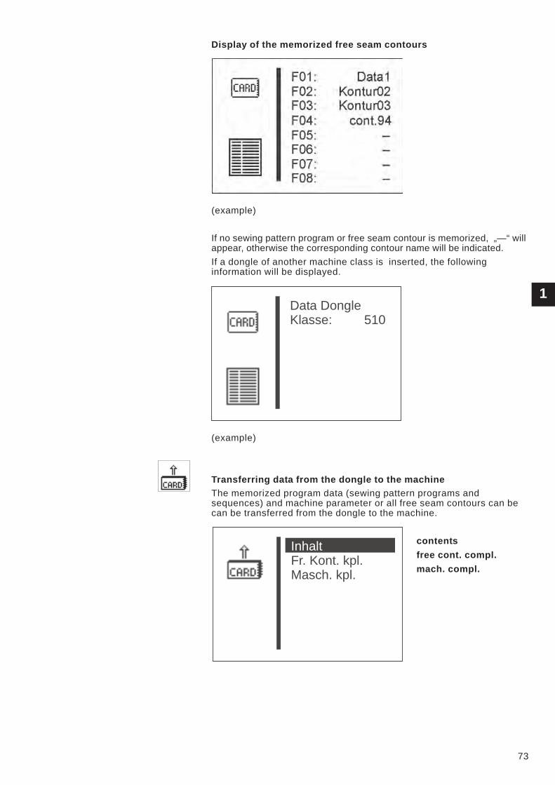
Display of the memorized free seam contours
(example)
If no sewing pattern program or free seam contour is memorized, „—“ will
appear, otherwise the corresponding contour name will be indicated.
If a dongle of another machine class is inserted, the following
information will be displayed.
(example)
Transferring data from the dongle to the machine
The memorized program data (sewing pattern programs and
sequences) and machine parameter or all free seam contours can be
can be transferred from the dongle to the machine.
contents
free cont. compl.
mach. compl.
1
73
Data Dongle
Klasse: 510
Inhalt
Fr. Kont. kpl.
Masch. kpl.
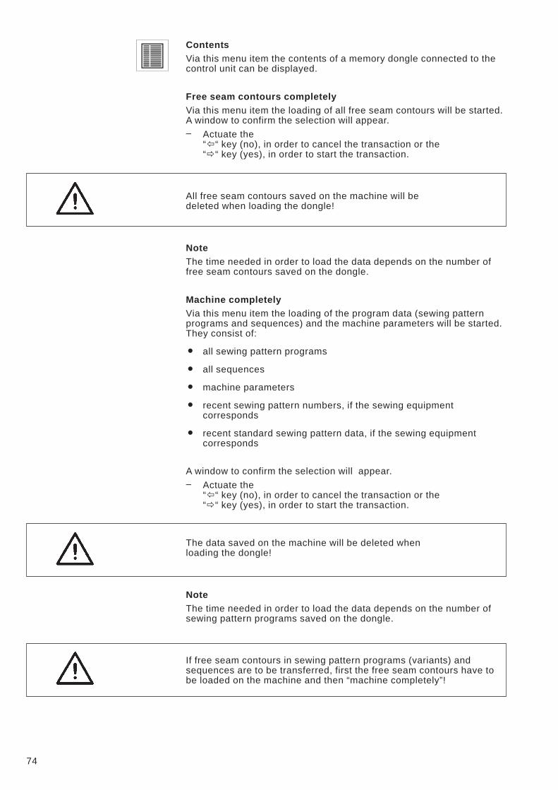
Contents
Via this menu item the contents of a memory dongle connected to the
control unit can be displayed.
Free seam contours completely
Via this menu item the loading of all free seam contours will be started.
A window to confirm the selection will appear.
– Actuate the
“�“ key (no), in order to cancel the transaction or the
“�“ key (yes), in order to start the transaction.
All free seam contours saved on the machine will be
deleted when loading the dongle!
Note
The time needed in order to load the data depends on the number of
free seam contours saved on the dongle.
Machine completely
Via this menu item the loading of the program data (sewing pattern
programs and sequences) and the machine parameters will be started.
They consist of:
� all sewing pattern programs
� all sequences
� machine parameters
� recent sewing pattern numbers, if the sewing equipment
corresponds
� recent standard sewing pattern data, if the sewing equipment
corresponds
A window to confirm the selection will appear.
– Actuate the
“�“ key (no), in order to cancel the transaction or the
“�“ key (yes), in order to start the transaction.
The data saved on the machine will be deleted when
loading the dongle!
Note
The time needed in order to load the data depends on the number of
sewing pattern programs saved on the dongle.
If free seam contours in sewing pattern programs (variants) and
sequences are to be transferred, first the free seam contours have to
be loaded on the machine and then “machine completely”!
74
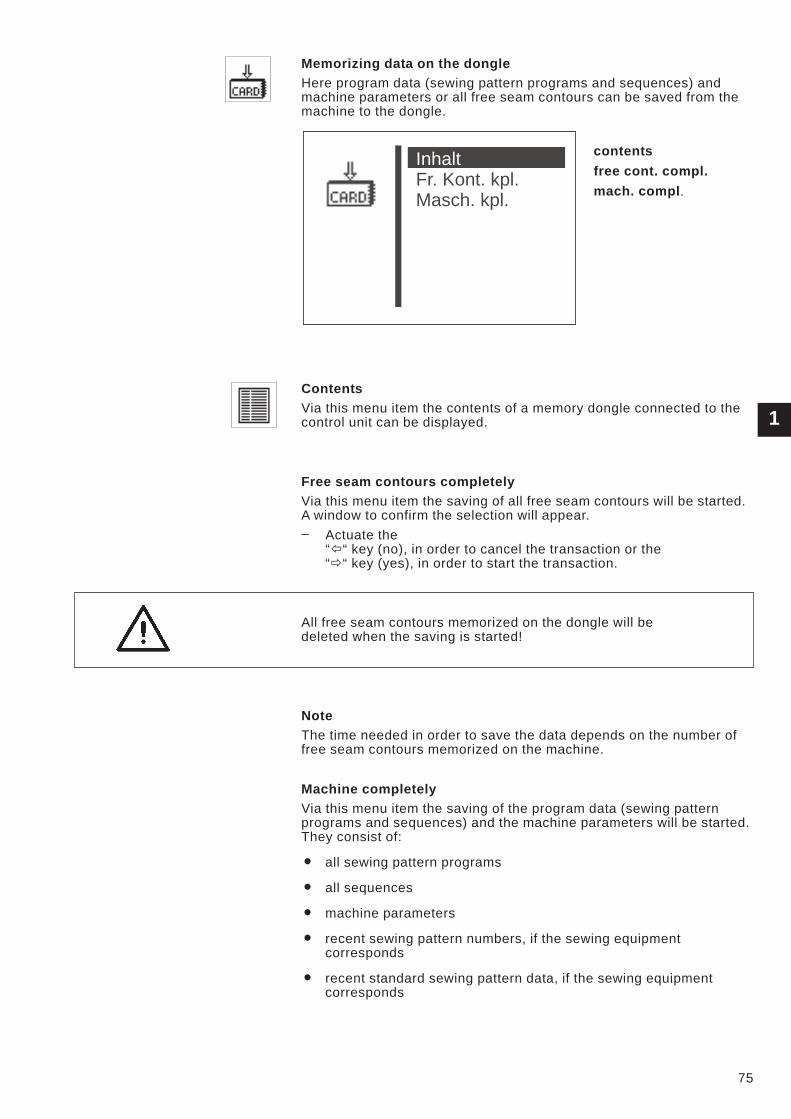
Memorizing data on the dongle
Here program data (sewing pattern programs and sequences) and
machine parameters or all free seam contours can be saved from the
machine to the dongle.
contents
free cont. compl.
mach. compl.
Contents
Via this menu item the contents of a memory dongle connected to the
control unit can be displayed.
Free seam contours completely
Via this menu item the saving of all free seam contours will be started.
A window to confirm the selection will appear.
– Actuate the
“�“ key (no), in order to cancel the transaction or the
“�“ key (yes), in order to start the transaction.
All free seam contours memorized on the dongle will be
deleted when the saving is started!
Note
The time needed in order to save the data depends on the number of
free seam contours memorized on the machine.
Machine completely
Via this menu item the saving of the program data (sewing pattern
programs and sequences) and the machine parameters will be started.
They consist of:
� all sewing pattern programs
� all sequences
� machine parameters
� recent sewing pattern numbers, if the sewing equipment
corresponds
� recent standard sewing pattern data, if the sewing equipment
corresponds
1
75
Inhalt
Fr. Kont. kpl.
Masch. kpl.
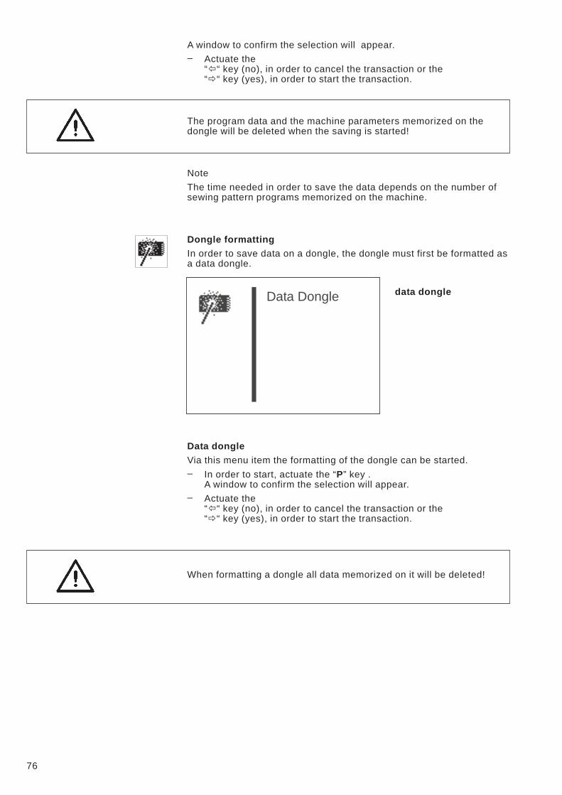
A window to confirm the selection will appear.
– Actuate the
“�“ key (no), in order to cancel the transaction or the
“�“ key (yes), in order to start the transaction.
The program data and the machine parameters memorized on the
dongle will be deleted when the saving is started!
Note
The time needed in order to save the data depends on the number of
sewing pattern programs memorized on the machine.
Dongle formatting
In order to save data on a dongle, the dongle must first be formatted as
a data dongle.
data dongle
Data dongle
Via this menu item the formatting of the dongle can be started.
– In order to start, actuate the “P” key .
A window to confirm the selection will appear.
– Actuate the
“�“ key (no), in order to cancel the transaction or the
“�“ key (yes), in order to start the transaction.
When formatting a dongle all data memorized on it will be deleted!
76
Data Dongle
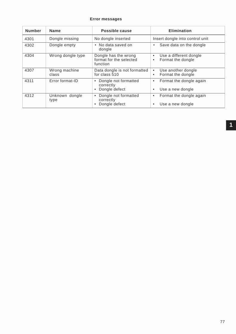
Error messages
Number Name Possible cause Elimination
4301 Dongle missing No dongle inserted Insert dongle into control unit
4302 Dongle empty • No data saved on
dongle
• Save data on the dongle
4304 Wrong dongle type Dongle has the wrong
format for the selected
function
• Use a different dongle
• Format the dongle
4307 Wrong machine
class
Data dongle is not formatted
for class 510
• Use another dongle
• Format the dongle
4311 Error format-ID • Dongle not formatted
correctly
• Dongle defect
• Format the dongle again
• Use a new dongle
4312 Unknown dongle
type
• Dongle not formatted
correctly
• Dongle defect
• Format the dongle again
• Use a new dongle
1
77
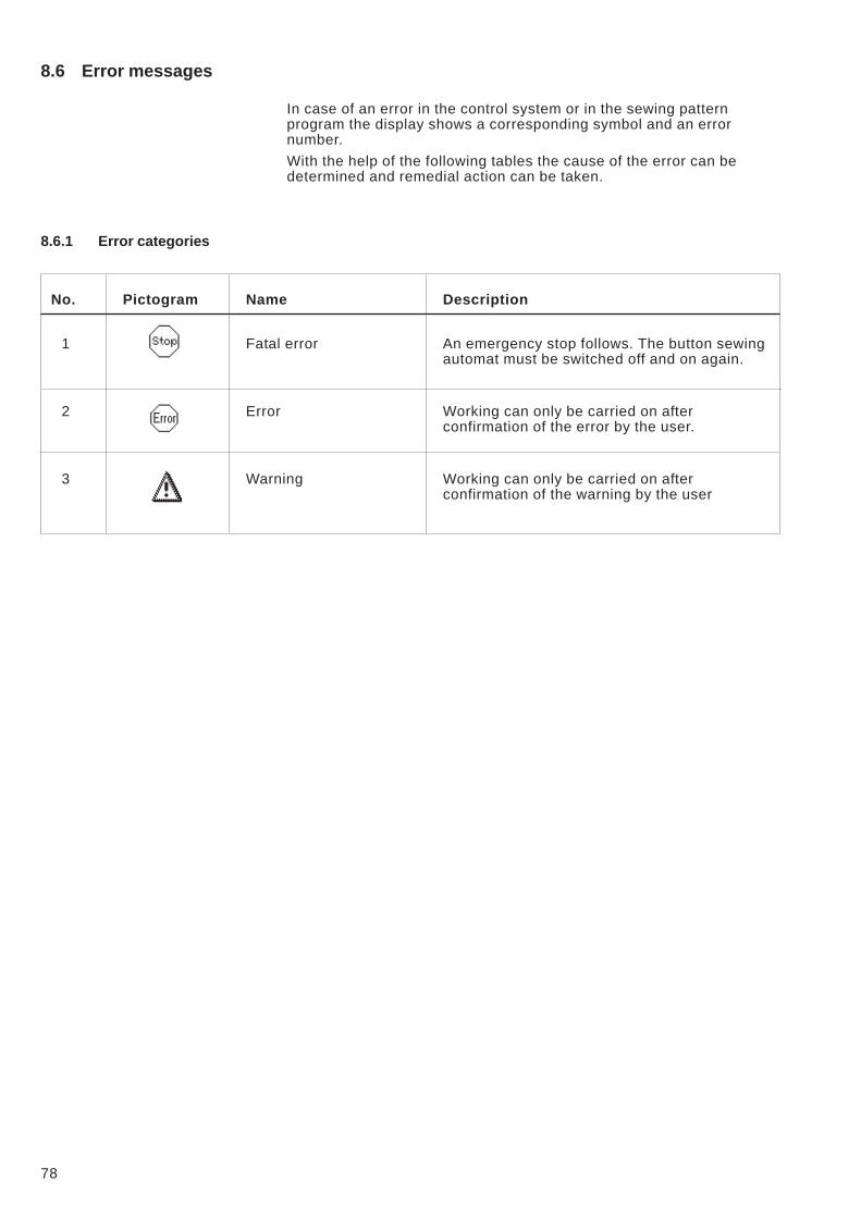
8.6 Error messages
In case of an error in the control system or in the sewing pattern
program the display shows a corresponding symbol and an error
number.
With the help of the following tables the cause of the error can be
determined and remedial action can be taken.
8.6.1 Error categories
No. Pictogram Name Description
1 Fatal error An emergency stop follows. The button sewing
automat must be switched off and on again.
2 Error Working can only be carried on after
confirmation of the error by the user.
3 Warning Working can only be carried on after
confirmation of the warning by the user
78
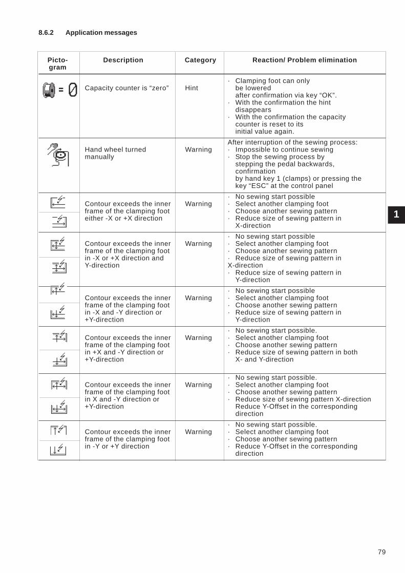
8.6.2 Application messages
Picto- Description Category Reaction/ Problem elimination
gram
Capacity counter is “zero” Hint
· Clamping foot can only
be lowered
after confirmation via key “OK”.
· With the confirmation the hint
disappears
· With the confirmation the capacity
counter is reset to its
initial value again.
Hand wheel turned
manually
Warning
After interruption of the sewing process:
· Impossible to continue sewing
· Stop the sewing process by
stepping the pedal backwards,
confirmation
by hand key 1 (clamps) or pressing the
key “ESC” at the control panel
Contour exceeds the inner
frame of the clamping foot
either -X or +X direction
Warning
· No sewing start possible
· Select another clamping foot
· Choose another sewing pattern
· Reduce size of sewing pattern in
X-direction
Contour exceeds the inner
frame of the clamping foot
in -X or +X direction and
Y-direction
Warning
· No sewing start possible
· Select another clamping foot
· Choose another sewing pattern
· Reduce size of sewing pattern in
X-direction
· Reduce size of sewing pattern in
Y-direction
Contour exceeds the inner
frame of the clamping foot
in -X and -Y direction or
+Y-direction
Warning
· No sewing start possible
· Select another clamping foot
· Choose another sewing pattern
· Reduce size of sewing pattern in
Y-direction
Contour exceeds the inner
frame of the clamping foot
in +X and -Y direction or
+Y-direction
Warning
· No sewing start possible.
· Select another clamping foot
· Choose another sewing pattern
· Reduce size of sewing pattern in both
X- and Y-direction
Contour exceeds the inner
frame of the clamping foot
in X and -Y direction or
+Y-direction
Warning
· No sewing start possible.
· Select another clamping foot
· Choose another sewing pattern
· Reduce size of sewing pattern X-direction
Reduce Y-Offset in the corresponding
direction
Contour exceeds the inner
frame of the clamping foot
in -Y or +Y direction
Warning
· No sewing start possible.
· Select another clamping foot
· Choose another sewing pattern
· Reduce Y-Offset in the corresponding
direction
1
79
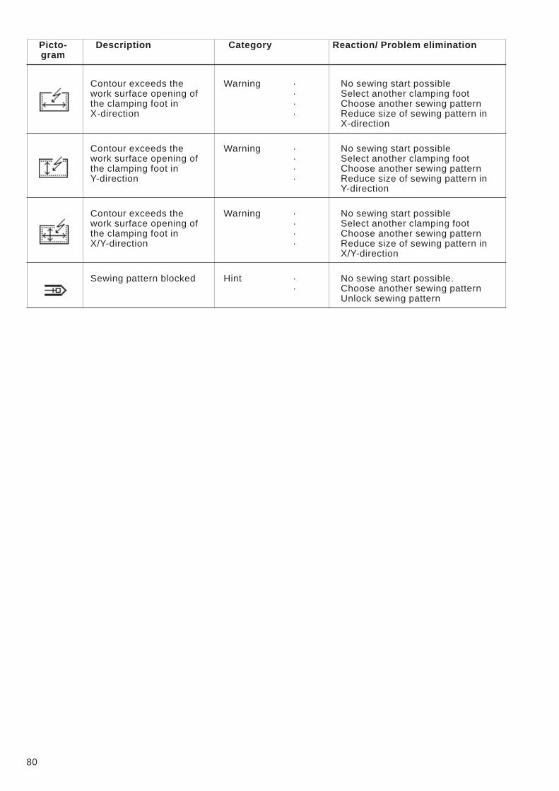
Picto- Description Category Reaction/ Problem elimination
gram
Contour exceeds the
work surface opening of
the clamping foot in
X-direction
Warning · No sewing start possible
· Select another clamping foot
· Choose another sewing pattern
· Reduce size of sewing pattern in
X-direction
Contour exceeds the
work surface opening of
the clamping foot in
Y-direction
Warning · No sewing start possible
· Select another clamping foot
· Choose another sewing pattern
· Reduce size of sewing pattern in
Y-direction
Contour exceeds the
work surface opening of
the clamping foot in
X/Y-direction
Warning · No sewing start possible
· Select another clamping foot
· Choose another sewing pattern
· Reduce size of sewing pattern in
X/Y-direction
Sewing pattern blocked Hint · No sewing start possible.
· Choose another sewing pattern
Unlock sewing pattern
80
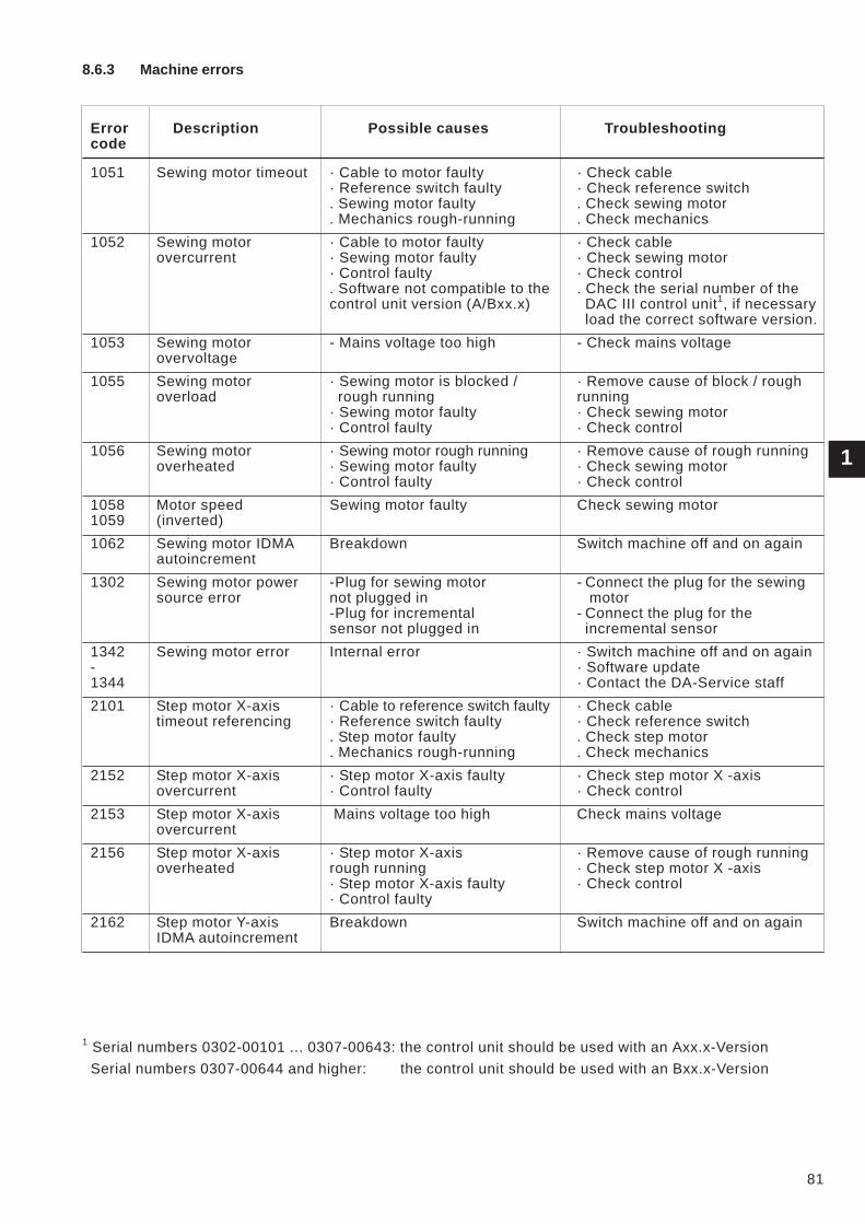
8.6.3 Machine errors
Error Description Possible causes Troubleshooting
code
1051 Sewing motor timeout · Cable to motor faulty
· Reference switch faulty
. Sewing motor faulty
. Mechanics rough-running
· Check cable
· Check reference switch
. Check sewing motor
. Check mechanics
1052 Sewing motor
overcurrent
· Cable to motor faulty
· Sewing motor faulty
· Control faulty
. Software not compatible to the
control unit version (A/Bxx.x)
· Check cable
· Check sewing motor
· Check control
. Check the serial number of the
DAC III control unit1, if necessary
load the correct software version.
1053 Sewing motor
overvoltage
- Mains voltage too high - Check mains voltage
1055 Sewing motor
overload
· Sewing motor is blocked /
rough running
· Sewing motor faulty
· Control faulty
· Remove cause of block / rough
running
· Check sewing motor
· Check control
1056 Sewing motor
overheated
· Sewing motor rough running
· Sewing motor faulty
· Control faulty
· Remove cause of rough running
· Check sewing motor
· Check control
1058
1059
Motor speed
(inverted)
Sewing motor faulty Check sewing motor
1062 Sewing motor IDMA
autoincrement
Breakdown Switch machine off and on again
1302 Sewing motor power
source error
-Plug for sewing motor
not plugged in
-Plug for incremental
sensor not plugged in
- Connect the plug for the sewing
motor
- Connect the plug for the
incremental sensor
1342
-
1344
Sewing motor error Internal error · Switch machine off and on again
· Software update
· Contact the DA-Service staff
2101 Step motor X-axis
timeout referencing
· Cable to reference switch faulty
· Reference switch faulty
. Step motor faulty
. Mechanics rough-running
· Check cable
· Check reference switch
. Check step motor
. Check mechanics
2152 Step motor X-axis
overcurrent
· Step motor X-axis faulty
· Control faulty
· Check step motor X -axis
· Check control
2153 Step motor X-axis
overcurrent
Mains voltage too high Check mains voltage
2156 Step motor X-axis
overheated
· Step motor X-axis
rough running
· Step motor X-axis faulty
· Control faulty
· Remove cause of rough running
· Check step motor X -axis
· Check control
2162 Step motor Y-axis
IDMA autoincrement
Breakdown Switch machine off and on again
1Serial numbers 0302-00101 ... 0307-00643: the control unit should be used with an Axx.x-Version
Serial numbers 0307-00644 and higher: the control unit should be used with an Bxx.x-Version
1
81
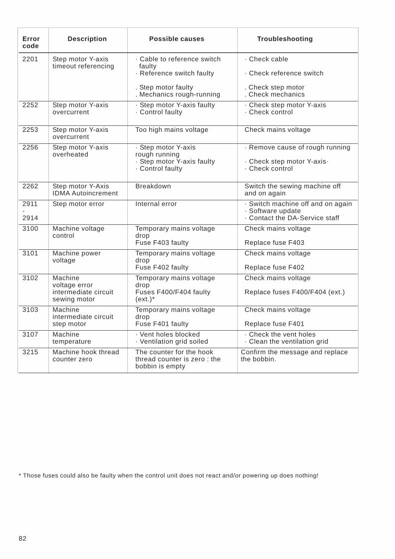
Error Description Possible causes Troubleshooting
code
2201 Step motor Y-axis
timeout referencing
· Cable to reference switch
faulty
· Reference switch faulty
. Step motor faulty
. Mechanics rough-running
· Check cable
· Check reference switch
. Check step motor
. Check mechanics
2252 Step motor Y-axis
overcurrent
· Step motor Y-axis faulty
· Control faulty
· Check step motor Y-axis
· Check control
2253 Step motor Y-axis
overcurrent
Too high mains voltage Check mains voltage
2256 Step motor Y-axis
overheated
· Step motor Y-axis
rough running
· Step motor Y-axis faulty
· Control faulty
· Remove cause of rough running
· Check step motor Y-axis·
· Check control
2262 Step motor Y-Axis
IDMA Autoincrement
Breakdown Switch the sewing machine off
and on again
2911
-
2914
Step motor error Internal error · Switch machine off and on again
· Software update
· Contact the DA-Service staff
3100 Machine voltage
control
Temporary mains voltage
drop
Fuse F403 faulty
Check mains voltage
Replace fuse F403
3101 Machine power
voltage
Temporary mains voltage
drop
Fuse F402 faulty
Check mains voltage
Replace fuse F402
3102 Machine
voltage error
intermediate circuit
sewing motor
Temporary mains voltage
drop
Fuses F400/F404 faulty
(ext.)*
Check mains voltage
Replace fuses F400/F404 (ext.)
3103 Machine
intermediate circuit
step motor
Temporary mains voltage
drop
Fuse F401 faulty
Check mains voltage
Replace fuse F401
3107 Machine
temperature
· Vent holes blocked
· Ventilation grid soiled
· Check the vent holes
· Clean the ventilation grid
3215 Machine hook thread
counter zero
The counter for the hook
thread counter is zero : the
bobbin is empty
Confirm the message and replace
the bobbin.
* Those fuses could also be faulty when the control unit does not react and/or powering up does nothing!
82
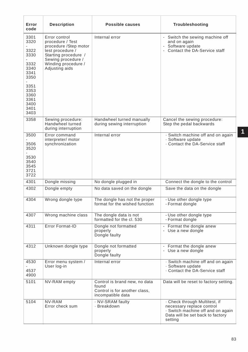
Error Description Possible causes Troubleshooting
code
3301
3320
-
3322
3330
-
3332
3340
3341
3350
-
3351
3353
3360
3361
3400
3401
3403
Error control
procedure / Test
procedure /Step motor
test procedure /
Starting procedure /
Sewing procedure /
Winding procedure /
Adjusting aids
Internal error - Switch the sewing machine off
and on again
- Software update
- Contact the DA-Service staff
3358 Sewing procedure:
Handwheel turned
during interruption
Handwheel turned manually
during sewing interruption
Cancel the sewing procedure:
Step the pedal backwards
3500
-
3506
3520
-
3530
3540
3545
3721
3722
Error command
interpreter/ motor
synchronization
Internal error · Switch machine off and on again
· Software update
· Contact the DA-Service staff
4301 Dongle missing No dongle plugged in Connect the dongle to the control
4302 Dongle empty No data saved on the dongle Save the data on the dongle
4304 Wrong dongle type The dongle has not the proper
format for the wished function
- Use other dongle type
- Format dongle
4307 Wrong machine class The dongle data is not
formatted for the cl. 530
- Use other dongle type
- Format dongle
4311 Error Format-ID Dongle not formatted
properly
Dongle faulty
- Format the dongle anew
- Use a new dongle
4312 Unknown dongle type Dongle not formatted
properly
Dongle faulty
- Format the dongle anew
- Use a new dongle
4530
-
4537
4900
Error menu system /
User log-in
Internal error · Switch machine off and on again
· Software update
· Contact the DA-Service staff
5101 NV-RAM empty Control is brand new, no data
found
Control is for another class,
incompatible data
Data will be reset to factory setting.
5104 NV-RAM
Error check sum
· NV-SRAM faulty
· Breakdown
· Check through Multitest, if
necessary replace control
· Switch machine off and on again
Data will be set back to factory
setting
83
1

Error Description Possible causes Troubleshooting
code
5804 Free Contours:
Wrong checksum
-
NV-SRAM faulty
-
Failure
- Check via Multitest,
check the control
- Switch the sewing machine off
and on again
Data will be reset to factory setting.
5808 Error free seam
contour
Cannot determine the
stitch number
Internal error - Switch the sewing machine off
and on again
- Software update
- Contact the DA-Service staff
5809 Free contours:
Max. number of
contour parts
Max. number of contour
parts (intermediate cut)
exceeded
Delete some intermediate cut in the
free contours
5810 Free contours:
Min. number of stitches
per contour part
Cannot keep the min. number
of stitches per contour part
Move some intermediate cut in the
free contours
5900 Error sequences -
Invalid sequence
number
Internal error · Switch machine off and on again
· Software update
· Contact the DA-Service staff
6151
-
6154
Error input / output Internal error · Switch machine off and on again
6351
-
6354
Error I²C Control faulty Replace control
Software update
Contact the DA-Service staff
6551
-
6554
6651
-
6653
6751
-
6761
6952
Error
Machine head
position /
AD-Converter /
Processor error /
Error step motor
driver
Internal error · Switch machine off and on again
· Software update
· Contact the DA-Service staff
7451
7453
7454
Communication Test
interface
Internal error Switch machine off and on again
7452
7455
Communication
test interface
· Transmission failure
· Cable of test interface faulty
· Internal error
- Switch off the source of
interference
- Replace cable
- Switch machine off and on again
7551
-
7555
7558
7559
Communication
control panel interface
Internal error - Switch off the source of
interference
- Replace cable
- Switch machine off and on again
7556
7557
Communication
control panel interface
· Transmission failure
· Cable of control panel
interface faulty
- Switch off the source of
interference
- Replace cable
- Switch machine off and on again
7700 Protocol: Max number
of repetition
· Transmission failure
· Cable of test interface faulty
- Switch off the source of
interference
- Replace cable
84
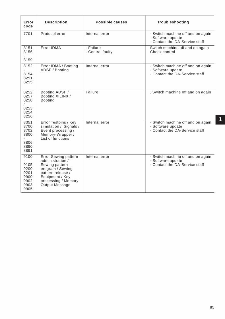
Error Description Possible causes Troubleshooting
code
7701 Protocol error Internal error · Switch machine off and on again
· Software update
· Contact the DA-Service staff
8151
8156
-
8159
Error IDMA · Failure
· Control faulty
Switch machine off and on again
Check control
8152
-
8154
8251
8255
Error IDMA / Booting
ADSP / Booting
Internal error · Switch machine off and on again
· Software update
· Contact the DA-Service staff
8252
8257
8258
/
8253
8254
8256
Booting ADSP /
Booting XILINX /
Booting
Failure . Switch machine off and on again
8351
8700
8702
8800
-
8806
8890
8891
Error Testpins / Key
simulation / Signals /
Event processing /
Memory-Wrapper /
List of functions
Internal error · Switch machine off and on again
· Software update
· Contact the DA-Service staff
9100
-
9105
9200
9201
9900
9902
9903
9905
Error Sewing pattern
administration /
Sewing pattern
program / Sewing
pattern release /
Equipment / Key
processing / Memory
Output Message
Internal error · Switch machine off and on again
· Software update
· Contact the DA-Service staff
85
1
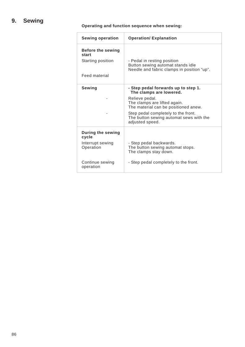
9. SewingOperating and function sequence when sewing:
Sewing operation Operation/ Explanation
Before the sewing
start
Starting position - Pedal in resting position
Button sewing automat stands idle
Needle and fabric clamps in position “up”.
Feed material
Sewing - Step pedal forwards up to step 1.
The clamps are lowered.
- Relieve pedal.
The clamps are lifted again.
The material can be positioned anew.
- Step pedal completely to the front.
The button sewing automat sews with the
adjusted speed.
During the sewing
cycle
Interrupt sewing - Step pedal backwards.
Operation The button sewing automat stops.
The clamps stay down.
Continue sewing - Step pedal completely to the front.
operation
86
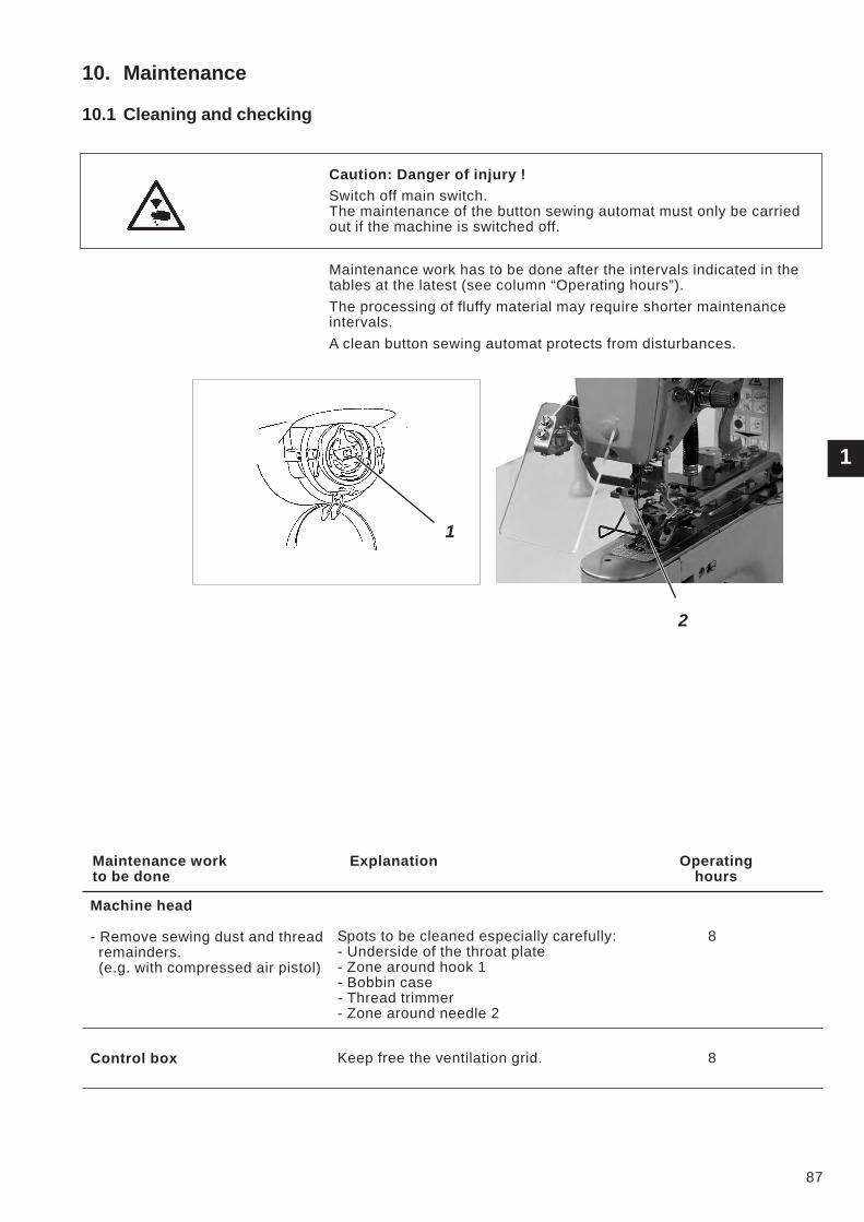
10. Maintenance
10.1 Cleaning and checking
Caution: Danger of injury !
Switch off main switch.
The maintenance of the button sewing automat must only be carried
out if the machine is switched off.
Maintenance work has to be done after the intervals indicated in the
tables at the latest (see column “Operating hours”).
The processing of fluffy material may require shorter maintenance
intervals.
A clean button sewing automat protects from disturbances.
Maintenance work Explanation Operating
to be done hours
Machine head
- Remove sewing dust and thread
remainders.
(e.g. with compressed air pistol)
Spots to be cleaned especially carefully:
- Underside of the throat plate
- Zone around hook 1
- Bobbin case
- Thread trimmer
- Zone around needle 2
8
Control box Keep free the ventilation grid. 8
87
1
1
2
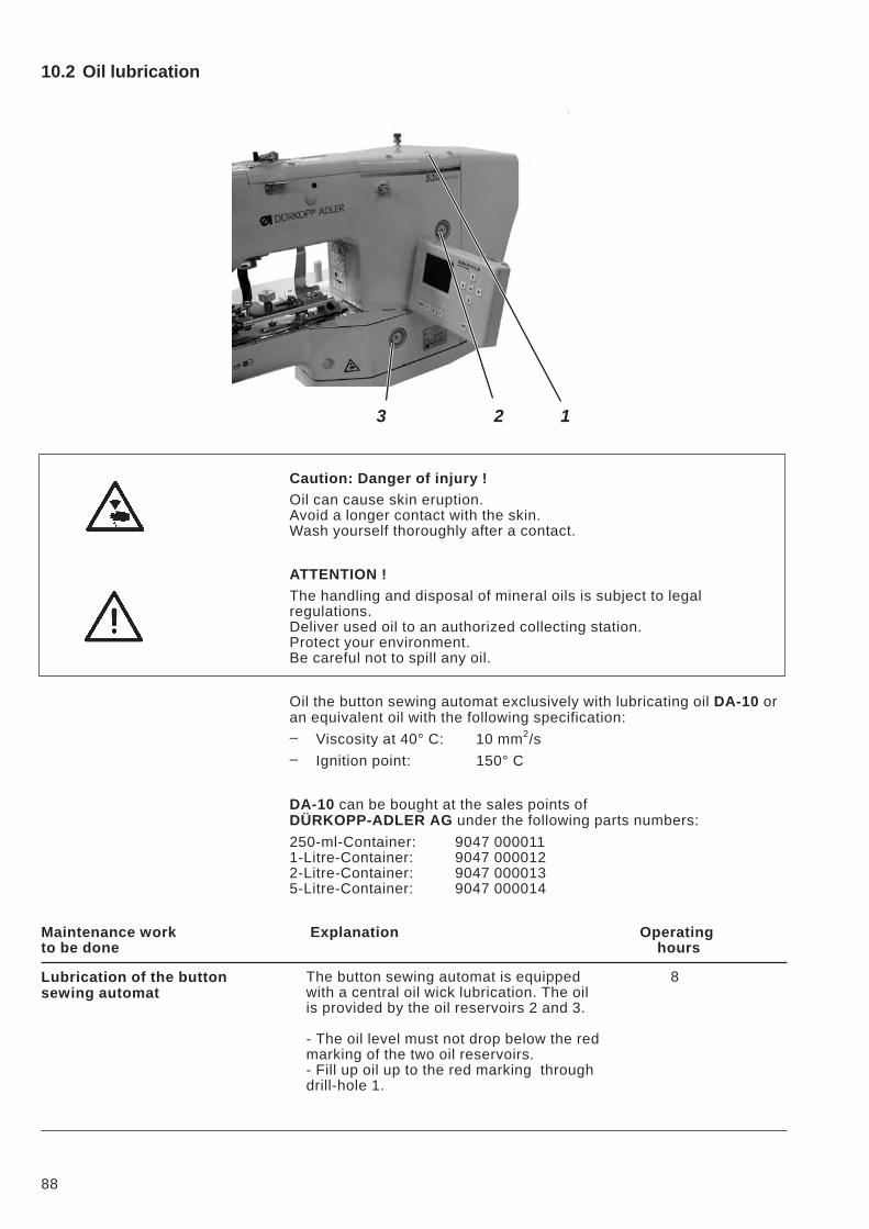
10.2 Oil lubrication
Caution: Danger of injury !
Oil can cause skin eruption.
Avoid a longer contact with the skin.
Wash yourself thoroughly after a contact.
ATTENTION !
The handling and disposal of mineral oils is subject to legal
regulations.
Deliver used oil to an authorized collecting station.
Protect your environment.
Be careful not to spill any oil.
Oil the button sewing automat exclusively with lubricating oil DA-10 or
an equivalent oil with the following specification:
– Viscosity at 40° C: 10 mm2/s
– Ignition point: 150° C
DA-10 can be bought at the sales points of
DÜRKOPP-ADLER AG under the following parts numbers:
250-ml-Container: 9047 000011
1-Litre-Container: 9047 000012
2-Litre-Container: 9047 000013
5-Litre-Container: 9047 000014
Maintenance work Explanation Operating
to be done hours
Lubrication of the button
sewing automat
The button sewing automat is equipped
with a central oil wick lubrication. The oil
is provided by the oil reservoirs 2 and 3.
- The oil level must not drop below the red
marking of the two oil reservoirs.
- Fill up oil up to the red marking through
drill-hole 1.
8
88
3 2 1
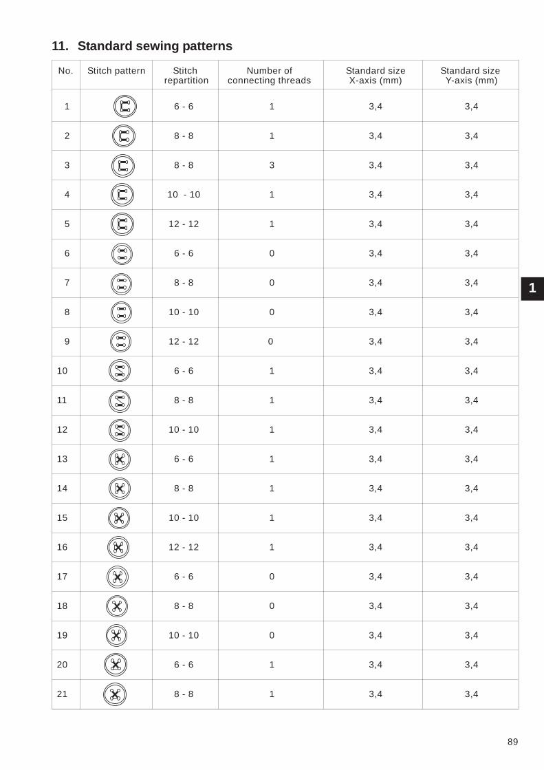
11. Standard sewing patterns
No. Stitch pattern Stitch Number of Standard size Standard size
repartition connecting threads X-axis (mm) Y-axis (mm)
1 6 - 6 1 3,4 3,4
2 8 - 8 1 3,4 3,4
3 8 - 8 3 3,4 3,4
4 10 - 10 1 3,4 3,4
5 12 - 12 1 3,4 3,4
6 6 - 6 0 3,4 3,4
7 8 - 8 0 3,4 3,4
8 10 - 10 0 3,4 3,4
9 12 - 12 0 3,4 3,4
10 6 - 6 1 3,4 3,4
11 8 - 8 1 3,4 3,4
12 10 - 10 1 3,4 3,4
13 6 - 6 1 3,4 3,4
14 8 - 8 1 3,4 3,4
15 10 - 10 1 3,4 3,4
16 12 - 12 1 3,4 3,4
17 6 - 6 0 3,4 3,4
18 8 - 8 0 3,4 3,4
19 10 - 10 0 3,4 3,4
20 6 - 6 1 3,4 3,4
21 8 - 8 1 3,4 3,4
1
89
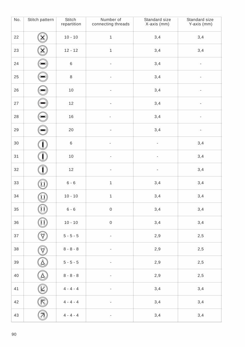
No. Stitch pattern Stitch Number of Standard size Standard size
repartition connecting threads X-axis (mm) Y-axis (mm)
22 10 - 10 1 3,4 3,4
23 12 - 12 1 3,4 3,4
24 6 - 3,4 -
25 8 - 3,4 -
26 10 - 3,4 -
27 12 - 3,4 -
28 16 - 3,4 -
29 20 - 3,4 -
30 6 - - 3,4
31 10 - - 3,4
32 12 - - 3,4
33 6 - 6 1 3,4 3,4
34 10 - 10 1 3,4 3,4
35 6 - 6 0 3,4 3,4
36 10 - 10 0 3,4 3,4
37 5 - 5 - 5 - 2,9 2,5
38 8 - 8 - 8 - 2,9 2,5
39 5 - 5 - 5 - 2,9 2,5
40 8 - 8 - 8 - 2,9 2,5
41 4 - 4 - 4 - 3,4 3,4
42 4 - 4 - 4 - 3,4 3,4
43 4 - 4 - 4 - 3,4 3,4
90
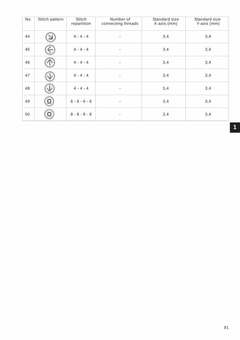
No. Stitch pattern Stitch Number of Standard size Standard size
repartition connecting threads X-axis (mm) Y-axis (mm)
44 4 - 4 - 4 - 3,4 3,4
45 4 - 4 - 4 - 3,4 3,4
46 4 - 4 - 4 - 3,4 3,4
47 4 - 4 - 4 - 3,4 3,4
48 4 - 4 - 4 - 3,4 3,4
49 6 - 6 - 6 - 6 - 3,4 3,4
50 8 - 8 - 8 - 8 - 3,4 3,4
1
91
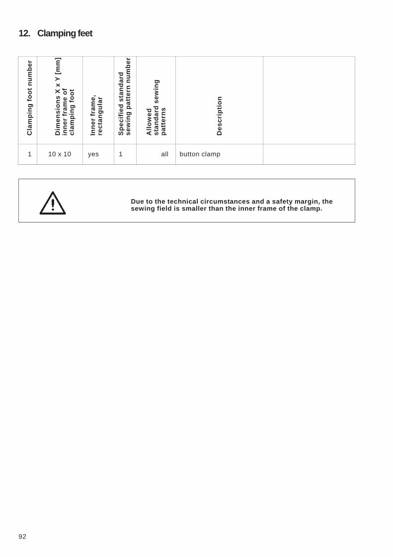
12. Clamping feetC
lam
pin
gfo
ot
nu
mb
er
Dim
en
sio
ns
Xx
Y[m
m]
inn
er
fra
me
of
cla
mp
ing
fo
ot
Inn
er
fra
me
,
re
cta
ng
ula
r
Sp
ec
ifie
ds
ta
nd
ard
se
win
gp
atte
rn
nu
mb
er
All
ow
ed
sta
nd
ard
se
win
g
pa
tte
rn
s
De
sc
rip
tio
n
1 10 x 10 yes 1 all button clamp
Due to the technical circumstances and a safety margin, the
sewing field is smaller than the inner frame of the clamp.
92
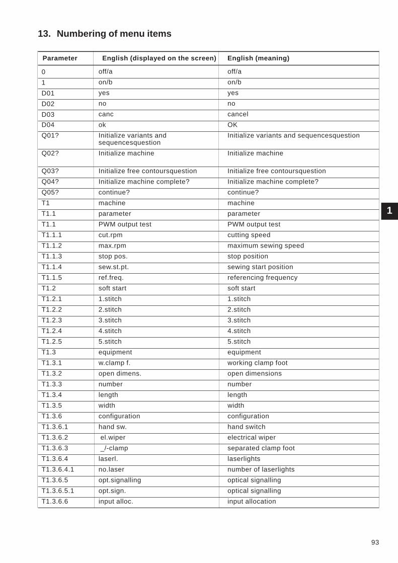
1
93
13. Numbering of menu items
Parameter English (displayed on the screen) English (meaning)
0 off/a off/a
1 on/b on/b
D01 yes yes
D02 no no
D03 canc cancel
D04 ok OK
Q01? Initialize variants and
sequencesquestion
Initialize variants and sequencesquestion
Q02? Initialize machine Initialize machine
Q03? Initialize free contoursquestion Initialize free contoursquestion
Q04? Initialize machine complete? Initialize machine complete?
Q05? continue? continue?
T1 machine machine
T1.1 parameter parameter
T1.1 PWM output test PWM output test
T1.1.1 cut.rpm cutting speed
T1.1.2 max.rpm maximum sewing speed
T1.1.3 stop pos. stop position
T1.1.4 sew.st.pt. sewing start position
T1.1.5 ref.freq. referencing frequency
T1.2 soft start soft start
T1.2.1 1.stitch 1.stitch
T1.2.2 2.stitch 2.stitch
T1.2.3 3.stitch 3.stitch
T1.2.4 4.stitch 4.stitch
T1.2.5 5.stitch 5.stitch
T1.3 equipment equipment
T1.3.1 w.clamp f. working clamp foot
T1.3.2 open dimens. open dimensions
T1.3.3 number number
T1.3.4 length length
T1.3.5 width width
T1.3.6 configuration configuration
T1.3.6.1 hand sw. hand switch
T1.3.6.2 el.wiper electrical wiper
T1.3.6.3 _/-clamp separated clamp foot
T1.3.6.4 laserl. laserlights
T1.3.6.4.1 no.laser number of laserlights
T1.3.6.5 opt.signalling optical signalling
T1.3.6.5.1 opt.sign. optical signalling
T1.3.6.6 input alloc. input allocation
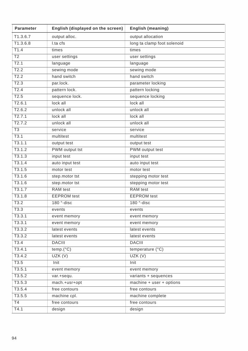
Parameter English (displayed on the screen) English (meaning)
T1.3.6.7 output alloc. output allocation
T1.3.6.8 l.ta cfs long ta clamp foot solenoid
T1.4 times times
T2 user settings user settings
T2.1 language language
T2.2 sewing mode sewing mode
T2.2 hand switch hand switch
T2.3 par.lock. parameter locking
T2.4 pattern lock. pattern locking
T2.5 sequence lock. sequence locking
T2.6.1 lock all lock all
T2.6.2 unlock all unlock all
T2.7.1 lock all lock all
T2.7.2 unlock all unlock all
T3 service service
T3.1 multitest multitest
T3.1.1 output test output test
T3.1.2 PWM output tst PWM output test
T3.1.3 input test input test
T3.1.4 auto input test auto input test
T3.1.5 motor test motor test
T3.1.6 step.motor tst stepping motor test
T3.1.6 step.motor tst stepping motor test
T3.1.7 RAM test RAM test
T3.1.8 EEPROM test EEPROM test
T3.2 180 °-disc 180 °-disc
T3.3 events events
T3.3.1 event memory event memory
T3.3.1 event memory event memory
T3.3.2 latest events latest events
T3.3.2 latest events latest events
T3.4 DACIII DACIII
T3.4.1 temp.(°C) temperature (°C)
T3.4.2 UZK (V) UZK (V)
T3.5 Init Init
T3.5.1 event memory event memory
T3.5.2 var.+sequ. variants + sequences
T3.5.3 mach.+usr+opt machine + user + options
T3.5.4 free contours free contours
T3.5.5 machine cpl. machine complete
T4 free contours free contours
T4.1 design design
94
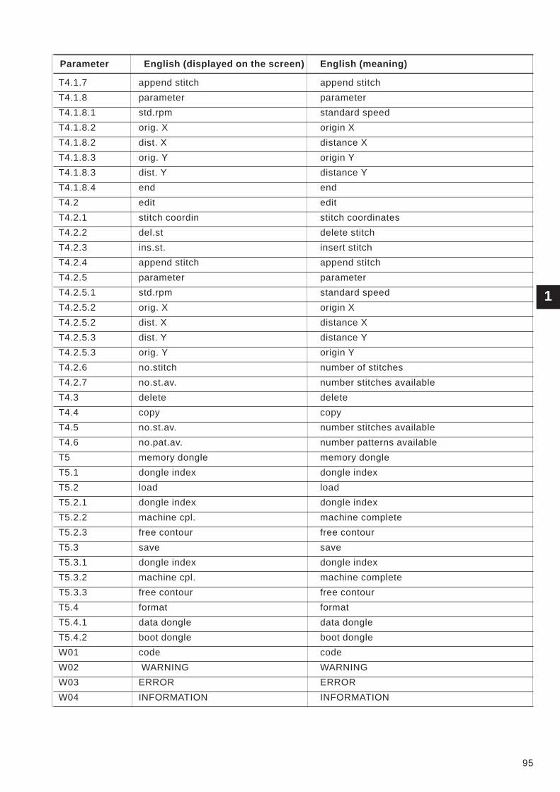
Parameter English (displayed on the screen) English (meaning)
T4.1.7 append stitch append stitch
T4.1.8 parameter parameter
T4.1.8.1 std.rpm standard speed
T4.1.8.2 orig. X origin X
T4.1.8.2 dist. X distance X
T4.1.8.3 orig. Y origin Y
T4.1.8.3 dist. Y distance Y
T4.1.8.4 end end
T4.2 edit edit
T4.2.1 stitch coordin stitch coordinates
T4.2.2 del.st delete stitch
T4.2.3 ins.st. insert stitch
T4.2.4 append stitch append stitch
T4.2.5 parameter parameter
T4.2.5.1 std.rpm standard speed
T4.2.5.2 orig. X origin X
T4.2.5.2 dist. X distance X
T4.2.5.3 dist. Y distance Y
T4.2.5.3 orig. Y origin Y
T4.2.6 no.stitch number of stitches
T4.2.7 no.st.av. number stitches available
T4.3 delete delete
T4.4 copy copy
T4.5 no.st.av. number stitches available
T4.6 no.pat.av. number patterns available
T5 memory dongle memory dongle
T5.1 dongle index dongle index
T5.2 load load
T5.2.1 dongle index dongle index
T5.2.2 machine cpl. machine complete
T5.2.3 free contour free contour
T5.3 save save
T5.3.1 dongle index dongle index
T5.3.2 machine cpl. machine complete
T5.3.3 free contour free contour
T5.4 format format
T5.4.1 data dongle data dongle
T5.4.2 boot dongle boot dongle
W01 code code
W02 WARNING WARNING
W03 ERROR ERROR
W04 INFORMATION INFORMATION
95
1
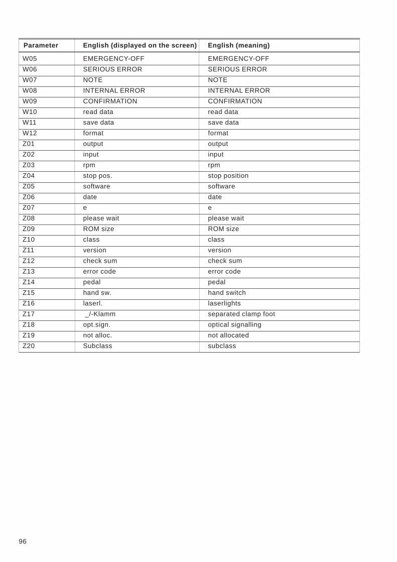
Parameter English (displayed on the screen) English (meaning)
W05 EMERGENCY-OFF EMERGENCY-OFF
W06 SERIOUS ERROR SERIOUS ERROR
W07 NOTE NOTE
W08 INTERNAL ERROR INTERNAL ERROR
W09 CONFIRMATION CONFIRMATION
W10 read data read data
W11 save data save data
W12 format format
Z01 output output
Z02 input input
Z03 rpm rpm
Z04 stop pos. stop position
Z05 software software
Z06 date date
Z07 e e
Z08 please wait please wait
Z09 ROM size ROM size
Z10 class class
Z11 version version
Z12 check sum check sum
Z13 error code error code
Z14 pedal pedal
Z15 hand sw. hand switch
Z16 laserl. laserlights
Z17 _/-Klamm separated clamp foot
Z18 opt.sign. optical signalling
Z19 not alloc. not allocated
Z20 Subclass subclass
96