Embed Size (px)
Citation preview

Zeszyty Naukowe 39(111) 161
Scientific Journals Zeszyty Naukowe Maritime University of Szczecin Akademia Morska w Szczecinie
2014, 39(111) pp. 161–168 2014, 39(111) s. 161–168 ISSN 1733-8670
CNC milling machine feed drive laboratory stand for purposes of velocity control algorithms prototyping
Paweł Waszczuk
West Pomeranian University of Technology, Faculty of Electrical Engineering Department of Industrial Automation and Robotics 70-313 Szczecin, ul. Sikorskiego 37, e-mail: [email protected]
Key words: feed drive control system, control algorithms rapid prototyping, servodrive control, MFC/IMC,
CNC
Abstract Article describes extended concept of digital servodrive velocity control algorithms rapid prototyping, which
is crucial component of milling machine feed drive equipped with ball screw. Approach presented here
describes the case where the user has no access to the internal control structure the servodrive (design wide-
spread in commercially applied CNC solutions), and can only use an additional signal (additive value of
torque/current), calculated on the basis of a comparison of the real object and its nominal dynamic model.
Introduction
Nowadays servodrives are exploited in many
technical applications which makes them one of
the most important group in terms of industrial
automation. Due to the extended feedback possibili-
ties servodrives provide a very high-precision, en-
suring a high dynamic motion, positioning, but also
the stable operation of the system at low speeds.
Because of their parameters servodrives have been
used as motor drives and a part of ball-screw feed
drive of CNC machines.
Modern control systems of CNC machines are
designed to ensure stability, good control and
robustness to disturbances and changing conditions
during machining operations. The servodrive effi-
ciency control in such applications is difficult,
because of their sensitivity to changes in the addi-
tional load and the control system parameters.
Manufacturers are constantly developing their
products and offer more and more features improv-
ing the milling process quality.
Newly developed, robust servo control algo-
rithms, that improve the properties of numerically
controlled machine feed units, in terms of the con-
trol quality and resistance to disturbances, increase
the performance of milling. From this point of view
an interesting group of control algorithms are
methods based on the plant model (Model-Based
Control). Publications [1, 2] shows exploitation of
the MFC concept (Model Following Control) in the
control of electric drives. Automatic systems utiliz-
ing the plant model can achieve very good quality
control, in cases, where the plant exhibits strong
non-linear properties, whereas crucial for the con-
trol system additional parameters vary in time.
CNC milling machine control systems
One of the key functional element of each CNC
machine is control system which determines the
utility of the device. The simplest CNC systems
offer basic functionalities, such as reading the tool
path from file or start of the machining process.
More sophisticated systems allow, for example, to
carry out simulation before machining, change tools
parameters and its route settings, tool diameter
compensation and visualization of the work pro-
gress in real time.
The vast majority of modern control systems
used in milling machines have closed architecture
and does not allow the user to any intervention on
their part, such as servodrive digital control algo-
rithms. The operator is forced to use pre-defined by
the manufacturer functions and do not have access
to the devices lower levels functionalities. Some

Paweł Waszczuk
162 Scientific Journals 39(111)
manufacturers of CNC machines give you the abil-
ity to modify their software and hardware solutions
for the CNC kernel level but it is very expensive
and very few people are able to afford it.
Development trends bring to the front CNC sys-
tems with open architecture, that allows to add new
dynamic states supervising functions of the ma-
chine in the time of the milling process. The studies
and projects (Osaka, OSEC, OMAC, Hoam – CNC)
in order to create a solution architecture that allows
the user to modify the algorithms in order to obtain
a flexible control system, and thereby adjust the
functionality of CNC machines for their own needs.
This topic is also goal of the research projects car-
ried out on West Pomeranian University of Tech-
nology, Szczecin [3, 4].
Methods of improving geometrical and motional quality in CNC control systems
The requirements set for modern CNC machine
control systems is steadily increasing due to the
growing expectations of users. New control systems
should provide possibilities of: ease of operation
and programming, openness and flexibility of the
structure, modularity construction and ensure high
process dynamics and precision control, safety and
robustness as well as durability and maintain spe-
cial concern for the natural environment.
Manufacturers of hardware and software solu-
tions for the CNC systems, in order to meet the
generally prevailing trends are constantly develop-
ing their products and extend them with new fea-
tures. Novel functionalities are supposed to im-
prove the machining parameters, increase stability
and extend the life of the tool. These solutions in-
clude, for example: nano-interpolation (GE Fanuc),
active vibration control (Mazak), an intelligent
thermal control (GF AgieCharmillesMikron), adap-
tive Feed Rate Control (Heidenhain), position con-
trol of machine tools (Sinumerik).
Servo drive control system structures in CNC feed drives
In a series of servo systems it is essential to
ensure precise movement trajectory interpolation
between the start and the end point. In commonly
exploited numerically controlled machines market
solutions of the servo control system, several types
of position control structures are used [5]. The most
common variant is the position control based on
a cascade of PI controllers. Such a system consists
of three feedback loops: current/torque control,
velocity control Rvm(s) and position control Rp(s).
Schematic architecture of the cascade controller
current / torque, velocity and position is shown in
figure 1.
Position and velocity control with fixed control-
lers settings in the structure shown in figure 1 gives
good performance in limited range of machine
operation, however, does not work for the entire
length of the feed axis [6]. Significant movement
parameters changes caused, for example, by such
phenomena as an alternating screw stiffness as
a function of the position, state a challenge for the
currently used control systems which entail a proto-
typing need of new algorithms and implementing
new solutions improving the quality and enhancing
the stability of the milling process.
Rapid prototyping of servodrive velocity control algorithms
Rapid prototyping can be divided into several
stages:
• Software-in-the-loop simulations – are sets of
specially prepared tests which main purpose is
to reduce the necessary time for implementing
a new solutions. Usually, every algorithm is first
tested in this way. Nowadays, one of the most
popular simulation environment is Matlab /
Simulink. As there are a few of tools available
on the market vendors provide possibility of
conducting numerical co-simulations. One of the
possibility enables the usage of LMS. AmeSim
(for physical modeling of complex mechatronic
structures) in connection with Matlab / Simulink
(for implementing and testing control part of the
system);
• Virtual prototyping – is a technique, allowing
software validation of created algorithms before
implementation on real plant. Its exploits hard-
ware resources of a PC for simulating behavior
Fig. 1. Cascade position control exploited in CNC machines; Pref(s) – reference position value, RP(s) – position controller,
Vref(s) – reference velocity value, Rvm(s) – velocity controller, Iqref(s) – current reference value, P(s) – plant, Iload(s) – external load,
Vakt(s) – actual velocity value, Pakt(s) – actual position value
CNC milling machine feed drive laboratory stand for purposes of velocity control algorithms prototyping
Zeszyty Naukowe 39(111) 163
of algorithms in various conditions. It allows
also consider undesirable functional states and
eliminate them before executed in the physical
process. Integrating a software simulation envi-
ronment on a PC with Real-time control system
gives additional opportunity to imitate the work
conditions and test algorithms and equipment.
• Hardware-in-the-loop simulations – the purpose
of this stage of prototyping is to try out differ-
ent, sophisticated concepts of control system al-
gorithms without the risk of damaging any of
the real plant’s elements. The hardware-in-the-
loop simulation provides an effective platform
by adding the complexity of the plant under con-
trol to the test platform. Implementation of this
stage of the prototype requires preparation pro-
cess and controller to be executable in real –time
conditions.
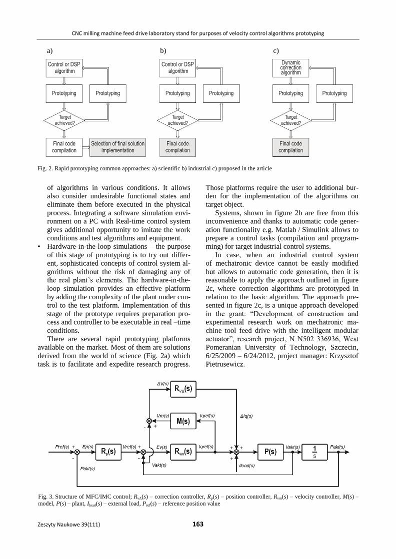
There are several rapid prototyping platforms
available on the market. Most of them are solutions
derived from the world of science (Fig. 2a) which
task is to facilitate and expedite research progress.
Those platforms require the user to additional bur-
den for the implementation of the algorithms on
target object.
Systems, shown in figure 2b are free from this
inconvenience and thanks to automatic code gener-
ation functionality e.g. Matlab / Simulink allows to
prepare a control tasks (compilation and program-
ming) for target industrial control systems.
In case, when an industrial control system
of mechatronic device cannot be easily modified
but allows to automatic code generation, then it is
reasonable to apply the approach outlined in figure
2c, where correction algorithms are prototyped in
relation to the basic algorithm. The approach pre-
sented in figure 2c, is a unique approach developed
in the grant: “Development of construction and
experimental research work on mechatronic ma-
chine tool feed drive with the intelligent modular
actuator”, research project, N N502 336936, West
Pomeranian University of Technology, Szczecin,
6/25/2009 – 6/24/2012, project manager: Krzysztof
Pietrusewicz.
a) b) c)
Fig. 2. Rapid prototyping common approaches: a) scientific b) industrial c) proposed in the article
Fig. 3. Structure of MFC/IMC control; Rv∆(s) – correction controller, Rp(s) – position controller, Rvm(s) – velocity controller, M(s) –
model, P(s) – plant, Iload(s) – external load, Pref(s) – reference position value

Paweł Waszczuk
164 Scientific Journals 39(111)
Reference signal dynamic correction based on plant’s model
Nonlinearities occurring in numerically con-
trolled machines due to their construction and oper-
ation are from the control point of view a process
disruption. Perturbations are caused by both: exter-
nal factors (e.g. load change), and internal arising
from the inner structure of the plant.
In the case of CNC machines an important ele-
ment for their proper operation is suitable tuning of
digital servodrive’s individual controllers, which is
the part of axis feed drive. Nowadays, commonly
used servo-control systems do not allow the realiza-
tion of the disturbance free process which results in
lower performance. One way of raising the level of
parameters precision adjustment and plant control,
could be a presented here algorithm called Model
Following Control [7, 8, 9].
If thedynamic model has been identified using
values of: reference current / torque and actual ve-
locity, it is possible to introduce additional correction
element which task is to calculate additional current
quantity used for plant control Iq(s) = [Iqref(s),
vakt(s)]. Plant output P(s) will track nominal model
output which equal internal correction block signal
vm(s) = M(s)Iqref(s). In presented correction element
the signal is generated by the additional controller
Iq(s) = Rv(s)[vm(s) – vakt(s)] basing on difference
between model output and actual velocity of con-
trolled feed drive.
Approach introduced in this article should be
considered as current feed-forward. Most of similar
solutions exploited in industrial applications has
been developed to increase control quality of
known machine operation conditions, therefore,
they tend to high sensitivity to parameters changes
in relation to nominal model.
Presented in figure 3 control structure using dy-
namic current correction of velocity control level,
based on MFC/IMC (Internal Model Control) algo-
rithm is significantly better in mentioned areas due
to the additional control degree, consisting of inter-
nal nominal model M(s) and correction controller
Rv(s) which ensure: tracking quality improvement
of velocity setpoint value, decreased influence of
plant P(s) parameter changes in relation to known
nominal model M(s), reduced impact of load
changes Iload(s) on the plant’s input. Features men-
tioned here will be demonstrated in the next section
of this article.
Sensitivity functions of analyzed plant
Sensitivity of control system is defined as its
susceptibility to external disturbances. It is desired
to obtain possibly low system sensitivity simulta-
neously maintaining proper performance. Sensi-
tivity functions are exploited to describe relations
between the plant’s model and the external disturb-
ances affecting its operation.
In this article the author presents comparison of
CNC axis feed drive velocity control system sensi-
tivity functions [10, 11]: conventional – cascade
and introduced here MFC/IMC. To compare both
structures transfer functions were defined (1) and
(2).
Nominal input sensitivity Sx0(s) (Fig. 4) reflects,
basing on calculated frequency response, tracking
quality of reference velocity value vref(s). The equa-
tions (1) and (2) show that the proposed system
(MFC / IMC) improves quality of reference veloci-
ty value tracking – absolute nominal input sensitivi-
ty function value equal to one denotes perfect track-
ing of setpoint value on the output. Calculations
which the results are shown in the figures 4 and 5,
were conducted for sensitivity functions described
with equations (1) and (2).
Nominal system sensitivity Sload(s) in function
of input load Iload(s) (Fig. 5) determined in the
frequency domain defines load dumping effect,
reduced to the controlled plant’s input. Absolute
value of function Sload(s) in velocity control system is
also called dynamic stiffness of axis feed drive.
Presented results shows that introduced MFC /
IMC control system of CNC axis ball screw feed
drive is an interesting alternative for conventional
cascade control architectures. By the cost of little
complexity increasing, user gets possibility of flex-
ible dynamic properties changing of axis feed drive
in the field of reference value tracking accuracy as
well as dynamic stiffness.
sIsRsP
sPsv
sRsP
sRsPsv
vmvm
vmloadrefaktclas
11
(1)
sIsRsPsRsMsRsPsRsP
sP
svsRsPsRsMsRsPsRsP
sMsRsRsPsv
vvmvvm
vvmvvm
vvm
load
refaktMFC/IMC
1
1
1
(2)
CNC milling machine feed drive laboratory stand for purposes of velocity control algorithms prototyping
Zeszyty Naukowe 39(111) 165
Fig. 4. Nominal input sensitivity (calculated for parameters
values used in simulation experiment)
Fig. 5. System susceptibility for additional input load Iload (s)
(calculated for parameters values used in simulation experi-
ment)
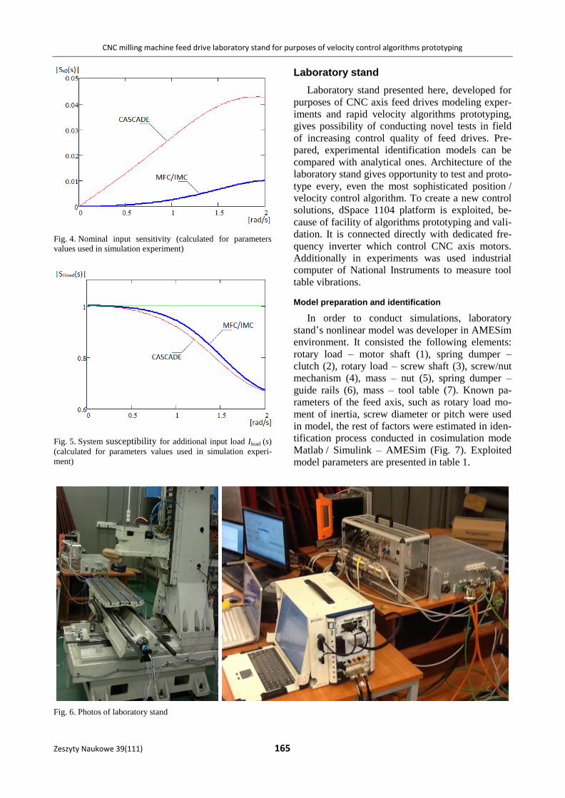
Laboratory stand
Laboratory stand presented here, developed for
purposes of CNC axis feed drives modeling exper-
iments and rapid velocity algorithms prototyping,
gives possibility of conducting novel tests in field
of increasing control quality of feed drives. Pre-
pared, experimental identification models can be
compared with analytical ones. Architecture of the
laboratory stand gives opportunity to test and proto-
type every, even the most sophisticated position /
velocity control algorithm. To create a new control
solutions, dSpace 1104 platform is exploited, be-
cause of facility of algorithms prototyping and vali-
dation. It is connected directly with dedicated fre-
quency inverter which control CNC axis motors.
Additionally in experiments was used industrial
computer of National Instruments to measure tool
table vibrations.
Model preparation and identification
In order to conduct simulations, laboratory
stand’s nonlinear model was developer in AMESim
environment. It consisted the following elements:
rotary load – motor shaft (1), spring dumper –
clutch (2), rotary load – screw shaft (3), screw/nut
mechanism (4), mass – nut (5), spring dumper –
guide rails (6), mass – tool table (7). Known pa-
rameters of the feed axis, such as rotary load mo-
ment of inertia, screw diameter or pitch were used
in model, the rest of factors were estimated in iden-
tification process conducted in cosimulation mode
Matlab / Simulink – AMESim (Fig. 7). Exploited
model parameters are presented in table 1.
Fig. 6. Photos of laboratory stand

Paweł Waszczuk
166 Scientific Journals 39(111)
Table 1. Model parameters
(1)
Parameter Value Unit
Moment of inertia 0.0017 kgm2
Coefficient of viscous friction 0.001 Nm/(rev/min)
Coulomb friction torque 0.2 Nm
Stiction torque 0.22 Nm
(2) Stiffness 360 Nm/rev
Damper rating 0.95493 Nm/(rad/s)
(3) Moment of inertia 0.0032 kgm2
Coefficient of viscous friction 0.0004 Nm/(rev/min)
(4)
Diameter 40 mm
Pitch 20 mm
Contact stiffness 1e9 N/m
Contact damping 1e6 N/(m/s)
Stiction coefficient 0.12 –
Coulomb friction coefficient 0.1 –
Stick displacement threshold 0.001 mm
(5)
Mass 5 kg
Stiction friction force 0 N
Coulomb friction force 0 N
Coefficient of viscous friction 0 N/(m/s)
(6) Spring rate 100,000 N/m
Damper rating 1,000 N/(m/s)
(7)
Mass 250 kg
Stiction friction force 90 N
Coulomb friction force 80 N
Coefficient of viscous friction 0.003 N/(m/s)
Figure 8 presents step responses of model with
estimated parameters and process from reference
velocity measurements. Because of plant nonlinear-
ity it was hard to select ideal factors that would
resemble its behavior. One of the best results is
shown below.
Fig. 8. Model and process step response comparison
Comparative simulation of MFC/IMC and cascade structures
Comparative simulation experiments of
MFC/IMC and typical cascade control structures
were made to show correctness of employed as-
sumptions. Exploited plant’s model is a base for
prototyping developed algorithms. Below, in figure
9 comparison of both responses – simulated plant’s
and its model for reference velocity is presented.
Fig. 7. Cosimulation mode Matlab/Simulink – AMESim

CNC milling machine feed drive laboratory stand for purposes of velocity control algorithms prototyping
Zeszyty Naukowe 39(111) 167
Fig. 9. Response of plant and model for reference velocity
Fig. 10. Response of typical cascade structure for reference velocity value
Fig. 11. Response of MFC/IMC structure for reference velocity value

Paweł Waszczuk
168 Scientific Journals 39(111)
Response for reference velocity value of typical
cascade control structure was simulated using
nonlinearplant model and PID controller. Tunes of
the controller were selected experimentally: Propor-
tional (P) = 40, Integral (I) = 6, Derivative (D) =
0.5. Figure 10 presents tracking of the reference
velocity by the plant’s PID output.
Assumption of the MFC/IMC architecture is
exploiting the same PID controller with identical
tunes as introduced in the cascade structure case.
Extra, linear model of the plant (P = 100, I = 20,
D = 2) is used to improve control quality. It calcu-
lates the additional correction signal which has an
impact on the main control value. Obtained simula-
tion results stands that presented in this
article structure gives positive outcomes in terms of
improving the tracking reference velocity value by
plant’s output. Figure 11 shows, how plant’s output
was forced to resemble model’s output in order to
adopt its behavior.
Conclusions
Presented in this article approach basing on
plant’s model ensures control quality improvement
of CNC axis feed drive. It is a result of noticeable
deviation reduction between reference and actual
velocity and may be considered as alternative for
commonly exploited cascade control architecture.
An undoubted advantage of the presented here solu-
tion is the possibility of implementation in a digital
servo drive system without interference with its
constituent algorithms. It can be introduced in eve-
ry system which allows user implementation of his
own correction/control algorithms using signals of:
actual velocity, reference current (from measure-
ments) and entering additional signal (additive ref-
erence current) which affect the main control value.
References
1. DOMEK S., DWORAK P., PIETRUSEWICZ K.: Hybrid Model-
Following Control Algorithm within the Motion Control
System. IEEE International Symposium on Industrial Elec-
tronics, 2009, 1476–1481.
2. PIETRUSEWICZ K., DWORAK P.: Robust Model-Following
Control for the DC Servo Drive. IEEE International Con-
ference on Industrial Technology, 2008, 1–6.
3. DOMEK S, PAJOR M, PIETRUSEWICZ K, URBAŃSKI Ł: Ekspe-
rymentalny system O.C.E.A.N. otwartego sterowania na-
pędami liniowymi. Inżynieria Maszyn 16, 2011, 40–49.
4. PIETRUSEWICZ K: CNC open architectures. Control Engi-
neering 55, 2008, 17–18.
5. SERKIES P.: Porównanie właściwości dynamicznych struk-
tur regulacji położenia w napędzie dwumasowym z kla-
sycznym regulatorem kaskadowym oraz regulatorem FDC.
Prace Naukowe Instytutu Maszyn, Napędów i Pomiarów
Elektrycznych Politechniki Wrocławskiej, Nr 65, 2011,
330–340.
6. ZHAO G., ZHAO Y., DONG A., ZHANG L.: Research on
Nonlinear PID Position Controller of CNC System. Pro-
ceedings of the IEEE International Conference on Automa-
tion and Logistics, 2008, Jinan, China, 2446–2450.
7. SKOCZOWSKI S., OSYPIUK R., PIETRUSEWICZ K.: Odporna
regulacja PID o dwóch stopniach swobody. Wydawnictwo
Naukowe PWN, 2006.
8. ZHENGJUN W., JUNZHENG W., JIANGBO Z., ZHIGANG L.:
Switching Gain Adaptive Sliding Mode Model-Following
Speed Control of PMSM. Proceedings of the 29th Chinese
Control Conference, 2010, Beijing, China, 3238–3243.
9. ZHI-JUN Y., XIAO-HUI Q.: Model-Following Sliding Mode
Controller Design for Flight Control Systems with Wind
Disturbances. Industrial Electronics and Applications,
2009, ICIEA 2009, 287–291.
10. PIETRUSEWICZ K., BIAŁY P., SKOCZOWSKI S.: MFC/IMC
system for processes with varying time-delay exemplified
by a 4 MW steam boiler. Pomiary Automatyka Kontrola
2004, 39–42.
11. SKOCZOWSKI S.: Control Systems Structures and Their Ro-
bustness. PAK 6, 2003, 5–9.