Embed Size (px)
Citation preview
8/4/2019 CNC TECHNOLOG
http://slidepdf.com/reader/full/cnc-technolog 1/115
CNC TECHNOLOGY
CHAPTER - 2
CP 04 02 08
D.JUSTIN BABU
8/4/2019 CNC TECHNOLOG
http://slidepdf.com/reader/full/cnc-technolog 2/115
INTRODUCTION TO CNC MACHINES
HISTORY OF NC / CNC / DNC
8/4/2019 CNC TECHNOLOG
http://slidepdf.com/reader/full/cnc-technolog 3/115
WHAT IS NUMERICAL CONTOL MACHINES
The machine tool in which the relative movements of the cutting tool and the
work piece and other relevant functions are controlled by the input of numerical
commands and data is called NUMERICAL CONTROL MACHINES
INTRODUCTION TO CNC MACHINES
8/4/2019 CNC TECHNOLOG
http://slidepdf.com/reader/full/cnc-technolog 4/115
First NC Milling was demonstrated in 1952 at the MASSACHUSETTSInstitute of Technology, USA.
In 1960 the Technology of Direct Numerical Control (DNC) was developed.
The earlier steps were to send the NC data directly to machine control bypassing the TAPE READER.
This way it was possible to control the NC machine tool directly by thecomputer, hence the name DIRECT NUMERICAL CONTROL(DNC).
DNC systems not only eliminated the less reliable TAPE READER but alsorepresented an important step towards total manufacturing automation.
INTRODUCTION TO CNC MACHINES
WHAT IS NUMERICAL CONTOL MACHINES
8/4/2019 CNC TECHNOLOG
http://slidepdf.com/reader/full/cnc-technolog 5/115
Components of Numerical Control
Machine
Part Program
Machine Control Unit (MCU)
8/4/2019 CNC TECHNOLOG
http://slidepdf.com/reader/full/cnc-technolog 6/115
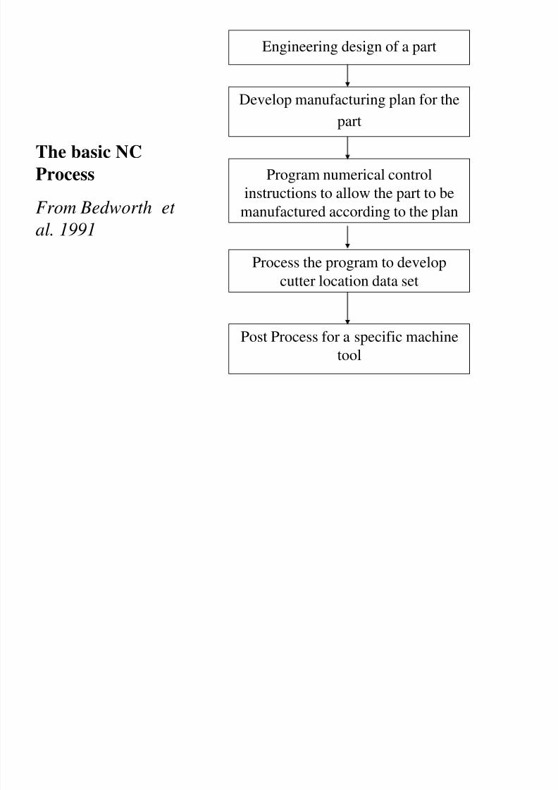
Engineering design of a part
Develop manufacturing plan for the
part
Program numerical control
instructions to allow the part to bemanufactured according to the plan
Process the program to develop
cutter location data set
Post Process for a specific machine
tool
The basic NC
Process
From Bedworth et
al. 1991
8/4/2019 CNC TECHNOLOG
http://slidepdf.com/reader/full/cnc-technolog 7/115
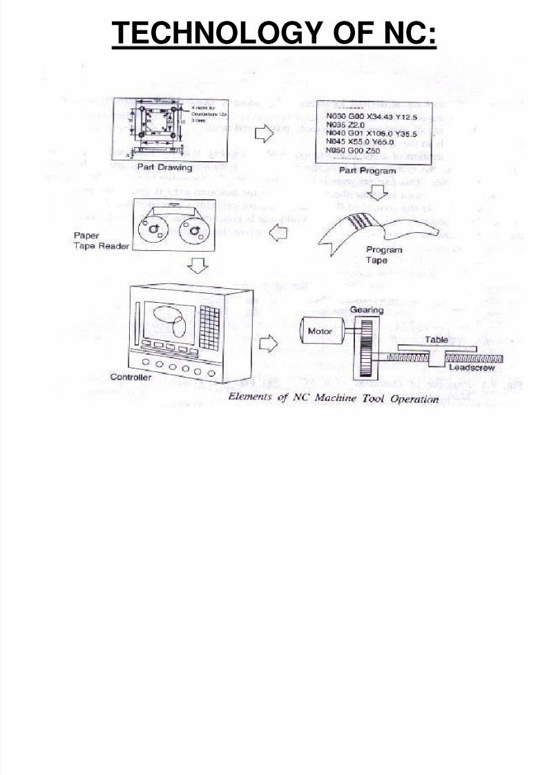
TECHNOLOGY OF NC:
8/4/2019 CNC TECHNOLOG
http://slidepdf.com/reader/full/cnc-technolog 8/115
TECHNOLOGY OF DNC:
Direct Numerical Control
It is defined as a manufacturing system in whicha number of machines are controlled by acomputer through direct connections
8/4/2019 CNC TECHNOLOG
http://slidepdf.com/reader/full/cnc-technolog 9/115
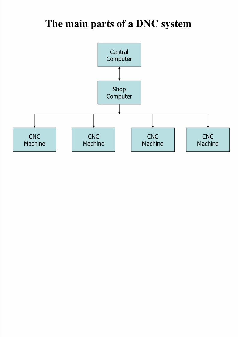
The main parts of a DNC system
CentralComputer
ShopComputer
CNCMachine
CNCMachine
CNCMachine
CNCMachine
8/4/2019 CNC TECHNOLOG
http://slidepdf.com/reader/full/cnc-technolog 10/115
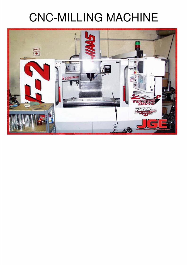
CNC-MILLING MACHINE
8/4/2019 CNC TECHNOLOG
http://slidepdf.com/reader/full/cnc-technolog 11/115
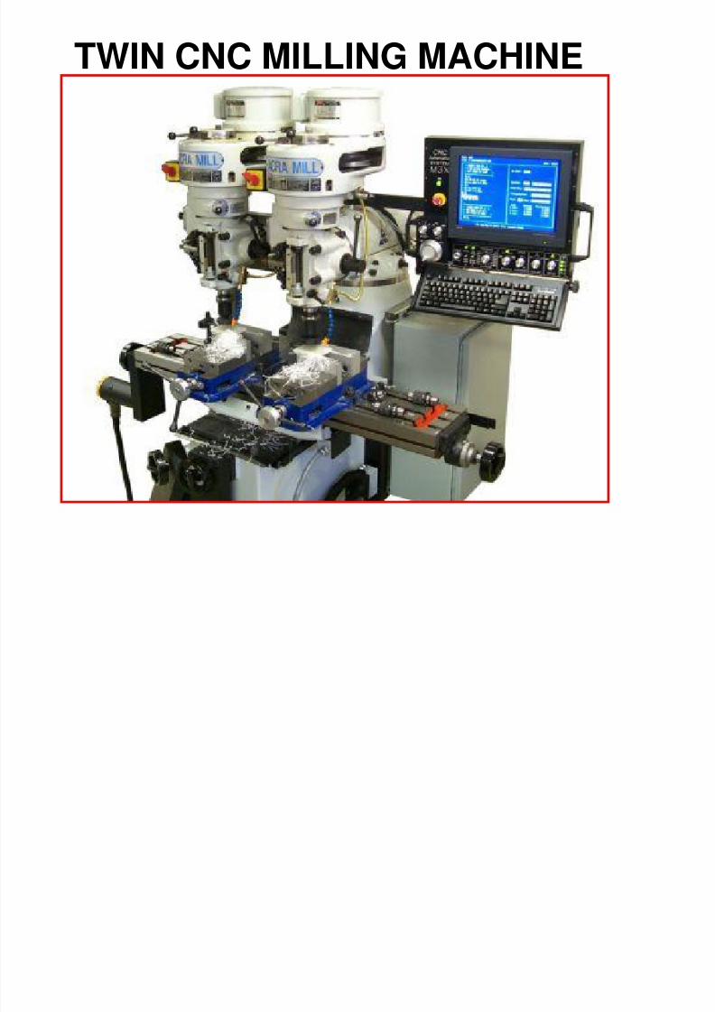
TWIN CNC MILLING MACHINE
8/4/2019 CNC TECHNOLOG
http://slidepdf.com/reader/full/cnc-technolog 12/115
CNC stands for Computer Numerical Control.
Prior to this, it was called NC, for Numerical Control.
In the early 1970's computers were introduced to these controls, hence thename change
What Is CNC?
8/4/2019 CNC TECHNOLOG
http://slidepdf.com/reader/full/cnc-technolog 13/115
CNC
In CNC machine tools, a dedicated computer is used
to perform all the basic functions of NC machine.
Additional features available in CNC compared to
NC is Part program can be directly typed using keyboard.
Part program can be edited which is stored in the memory.
Sub programming can be done.
Cutting tool path can be generated.
We can obtain information regarding machine utilization.
8/4/2019 CNC TECHNOLOG
http://slidepdf.com/reader/full/cnc-technolog 14/115
WHAT IS NUMERICAL CONTOL MACHINES
The present generations of CNC machines are designed to meet the
requirements of HIGH PRODUCTIVITY, FLEXIBILITY and HIGH RELIABLITY
to produce components of HIGH QUALITY and ACCURACY levels combined
with REDUCTION IN MANUFACTURING COST.
8/4/2019 CNC TECHNOLOG
http://slidepdf.com/reader/full/cnc-technolog 15/115
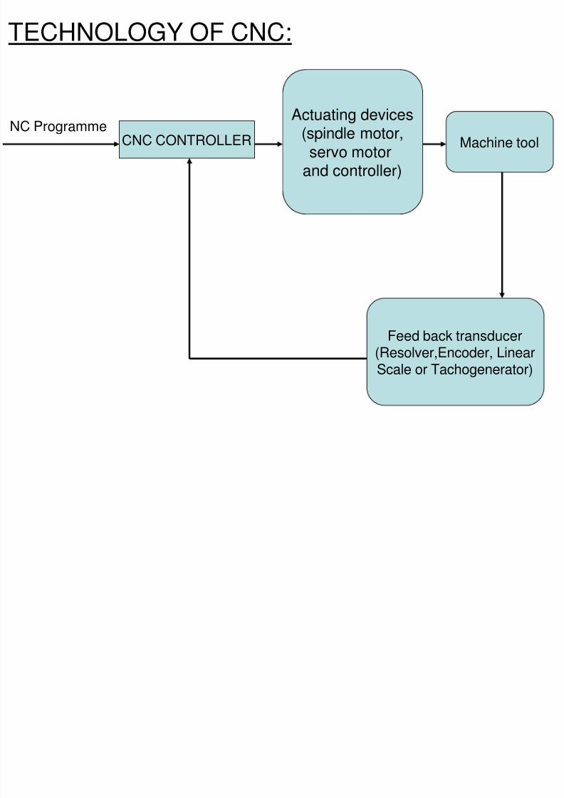
TECHNOLOGY OF CNC:
CNC CONTROLLERNC Programme
Actuating devices(spindle motor,servo motor
and controller)
Machine tool
Feed back transducer(Resolver,Encoder, LinearScale or Tachogenerator)
8/4/2019 CNC TECHNOLOG
http://slidepdf.com/reader/full/cnc-technolog 16/115
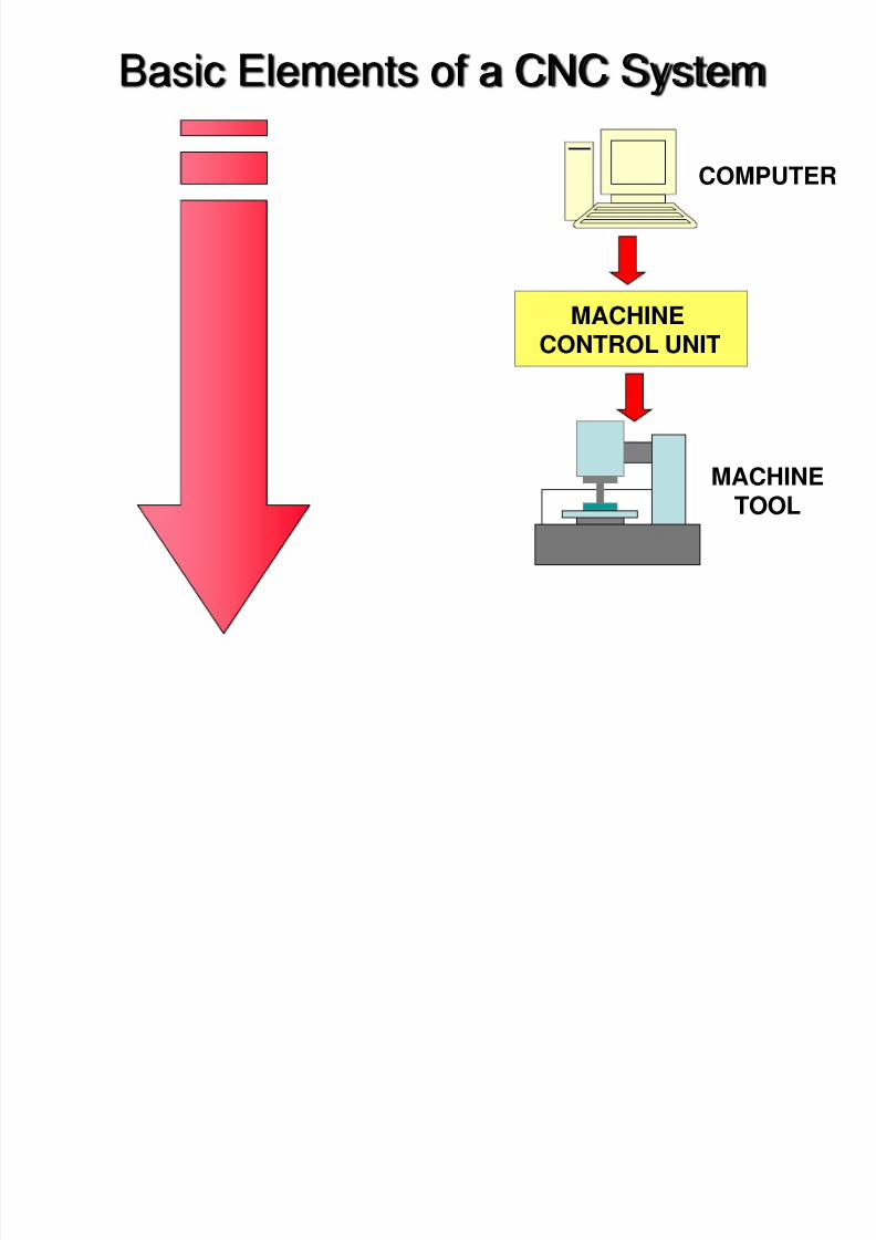
Basic Elements of a CNC System
COMPUTER
MACHINETOOL
MACHINECONTROL UNIT
8/4/2019 CNC TECHNOLOG
http://slidepdf.com/reader/full/cnc-technolog 17/115
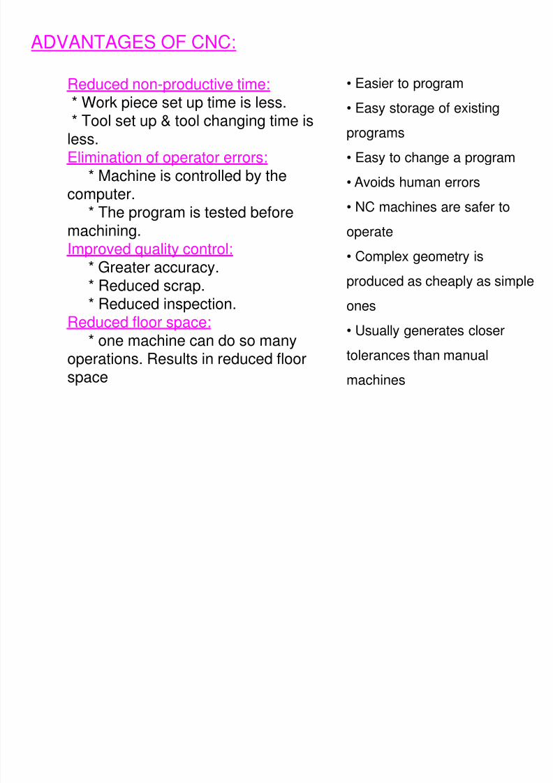
ADVANTAGES OF CNC:
Reduced non-productive time:
* Work piece set up time is less.* Tool set up & tool changing time is
less.Elimination of operator errors:
* Machine is controlled by the
computer.* The program is tested before
machining.Improved quality control:
* Greater accuracy.
* Reduced scrap.* Reduced inspection.Reduced floor space:
* one machine can do so manyoperations. Results in reduced floorspace
• Easier to program
• Easy storage of existing
programs
• Easy to change a program
• Avoids human errors
• NC machines are safer to
operate
• Complex geometry is
produced as cheaply as simple
ones
• Usually generates closer
tolerances than manual
machines
8/4/2019 CNC TECHNOLOG
http://slidepdf.com/reader/full/cnc-technolog 18/115
• Higher investment cost (CNC machine is more sophisticated and
complex technology).
• Higher maintenance cost (CNC is more complex and moreaccurate).
• Need of trained personnel (Certain aspects of these machineoperations require higher-level skill than a conventional machine).
• Planned support facility:Most of the preparatory work for CNC is done away from the machine.
Hence to reduce machine idle time proper planning is required.
DISADVANTAGES CNC MACHINE
8/4/2019 CNC TECHNOLOG
http://slidepdf.com/reader/full/cnc-technolog 19/115
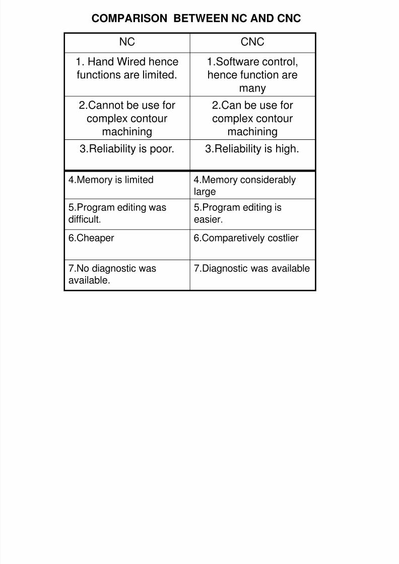
COMPARISON BETWEEN NC AND CNC
NC CNC
1. Hand Wired hence
functions are limited.
1.Software control,
hence function aremany
2.Cannot be use forcomplex contour
machining
2.Can be use forcomplex contour
machining
3.Reliability is poor. 3.Reliability is high.
4.Memory is limited 4.Memory considerablylarge
5.Program editing wasdifficult.
5.Program editing iseasier.
6.Cheaper 6.Comparetively costlier
7.No diagnostic was
available.
7.Diagnostic was available
8/4/2019 CNC TECHNOLOG
http://slidepdf.com/reader/full/cnc-technolog 20/115
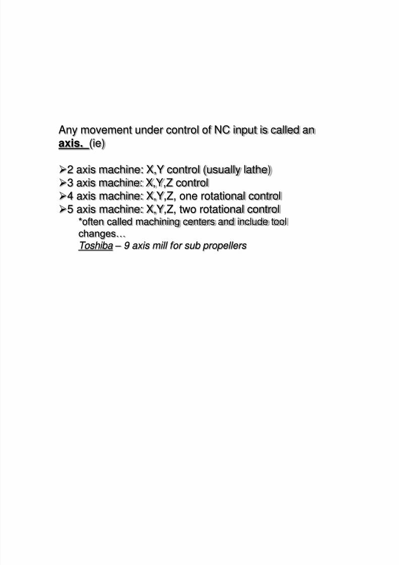
Any movement under control of NC input is called an
axis. (ie)
2 axis machine: X,Y control (usually lathe)3 axis machine: X,Y,Z control4 axis machine: X,Y,Z, one rotational control
5 axis machine: X,Y,Z, two rotational control*often called machining centers and include toolchanges… Toshiba – 9 axis mill for sub propellers
8/4/2019 CNC TECHNOLOG
http://slidepdf.com/reader/full/cnc-technolog 21/115
8/4/2019 CNC TECHNOLOG
http://slidepdf.com/reader/full/cnc-technolog 22/115
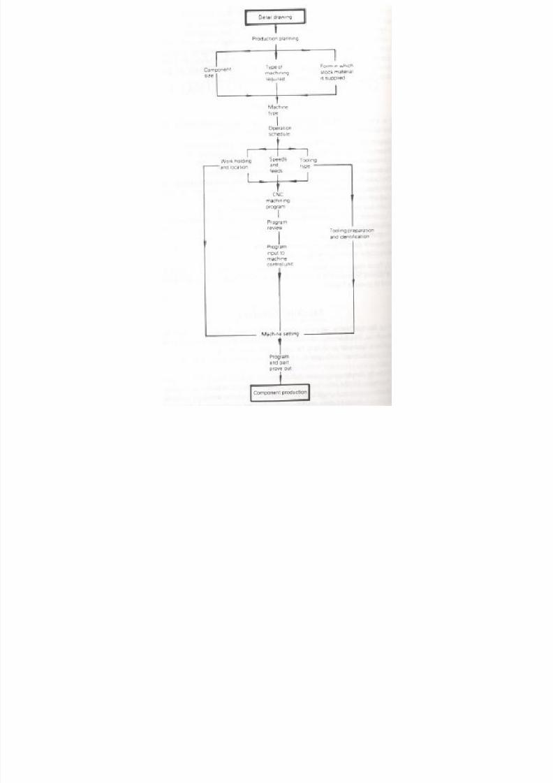
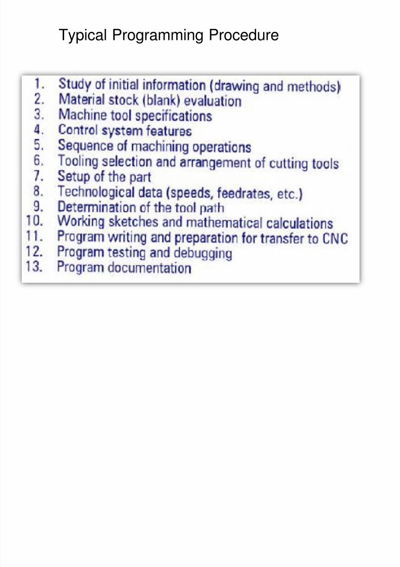
Typical Programming Procedure
8/4/2019 CNC TECHNOLOG
http://slidepdf.com/reader/full/cnc-technolog 23/115
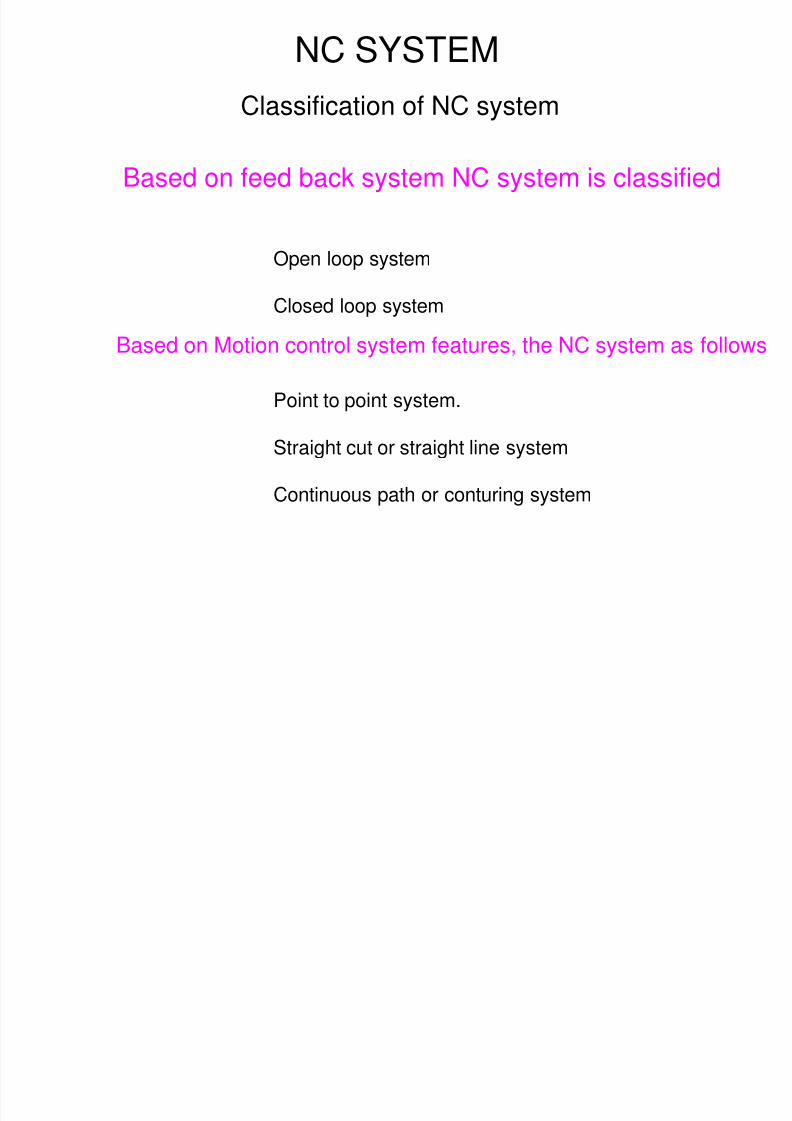
NC SYSTEM
Based on feed back system NC system is classified
Classification of NC system
Open loop system
Closed loop system
Point to point system.
Straight cut or straight line system
Continuous path or conturing system
Based on Motion control system features, the NC system as follows
8/4/2019 CNC TECHNOLOG
http://slidepdf.com/reader/full/cnc-technolog 24/115
Classification of NC system
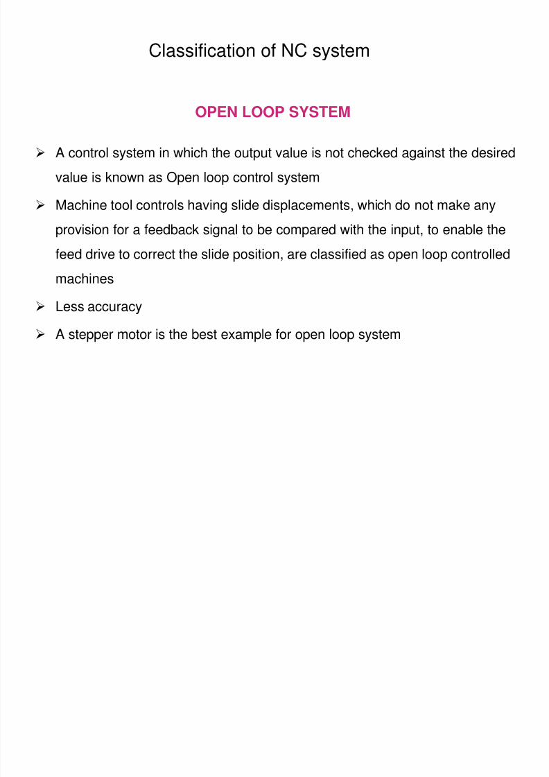
OPEN LOOP SYSTEM
A control system in which the output value is not checked against the desired
value is known as Open loop control system
Machine tool controls having slide displacements, which do not make any
provision for a feedback signal to be compared with the input, to enable the
feed drive to correct the slide position, are classified as open loop controlled
machines
Less accuracy
A stepper motor is the best example for open loop system
8/4/2019 CNC TECHNOLOG
http://slidepdf.com/reader/full/cnc-technolog 25/115
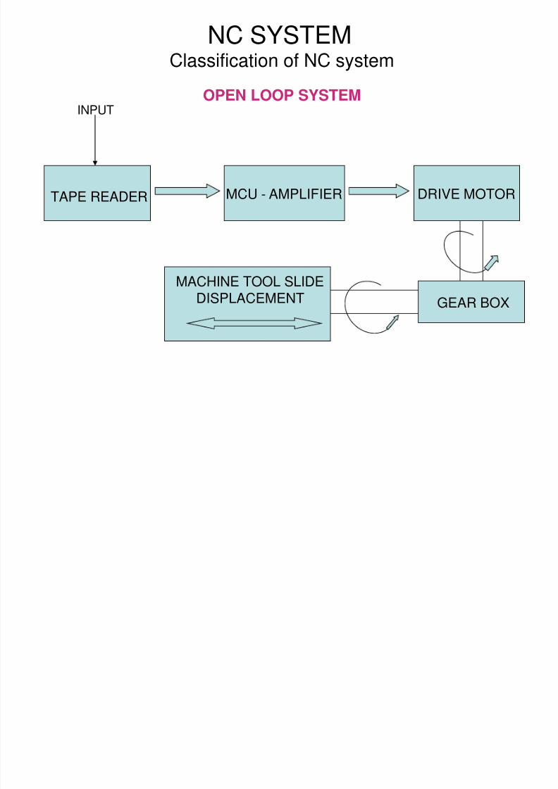
NC SYSTEMClassification of NC system
MCU - AMPLIFIER DRIVE MOTOR
INPUT
MACHINE TOOL SLIDE
DISPLACEMENT GEAR BOX
TAPE READER
OPEN LOOP SYSTEM
8/4/2019 CNC TECHNOLOG
http://slidepdf.com/reader/full/cnc-technolog 26/115
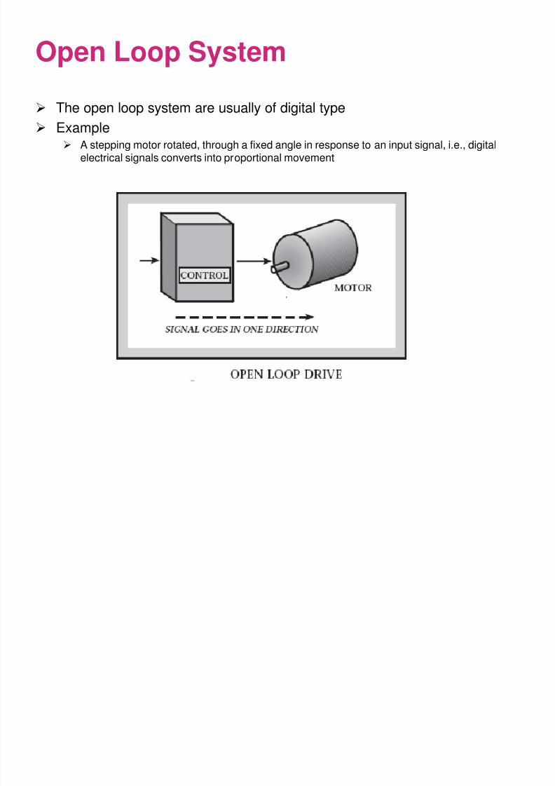
Open Loop System
The open loop system are usually of digital type
Example A stepping motor rotated, through a fixed angle in response to an input signal, i.e., digital
electrical signals converts into proportional movement
8/4/2019 CNC TECHNOLOG
http://slidepdf.com/reader/full/cnc-technolog 27/115
Applications of Open Loop Control System
• Light duty machines• Less investment
• No need of much accuracy
Disadvantages• Backlash error in lead screw
• Less accurate
Note• SLO-SYN stepper motor used to avoid the drawbacks in open loop
control system
8/4/2019 CNC TECHNOLOG
http://slidepdf.com/reader/full/cnc-technolog 28/115
NC SYSTEM
Classification of NC system
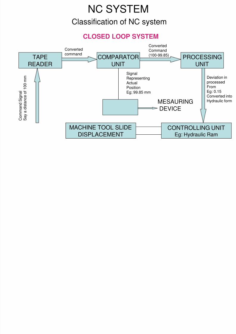
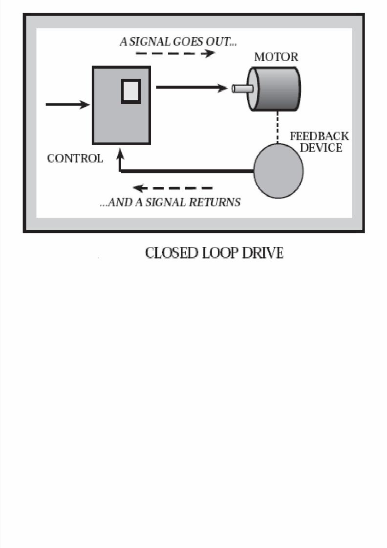
CLOSED LOOP SYSTEM
• A control system in which movement of the machine slide is checked and
corrected with respect to input signals and mainly by the signals from the
feedback device
• The feed back from the monitoring device is then compared with the input
information and the slide position is regulated by the servo system until
it agrees with the desired position
• The use of closed loop control system enable the displacement or
position of a slide to be achieved to a very high degree of accuracy by using
a measuring or monitoring device to determine the slide displacement
8/4/2019 CNC TECHNOLOG
http://slidepdf.com/reader/full/cnc-technolog 29/115
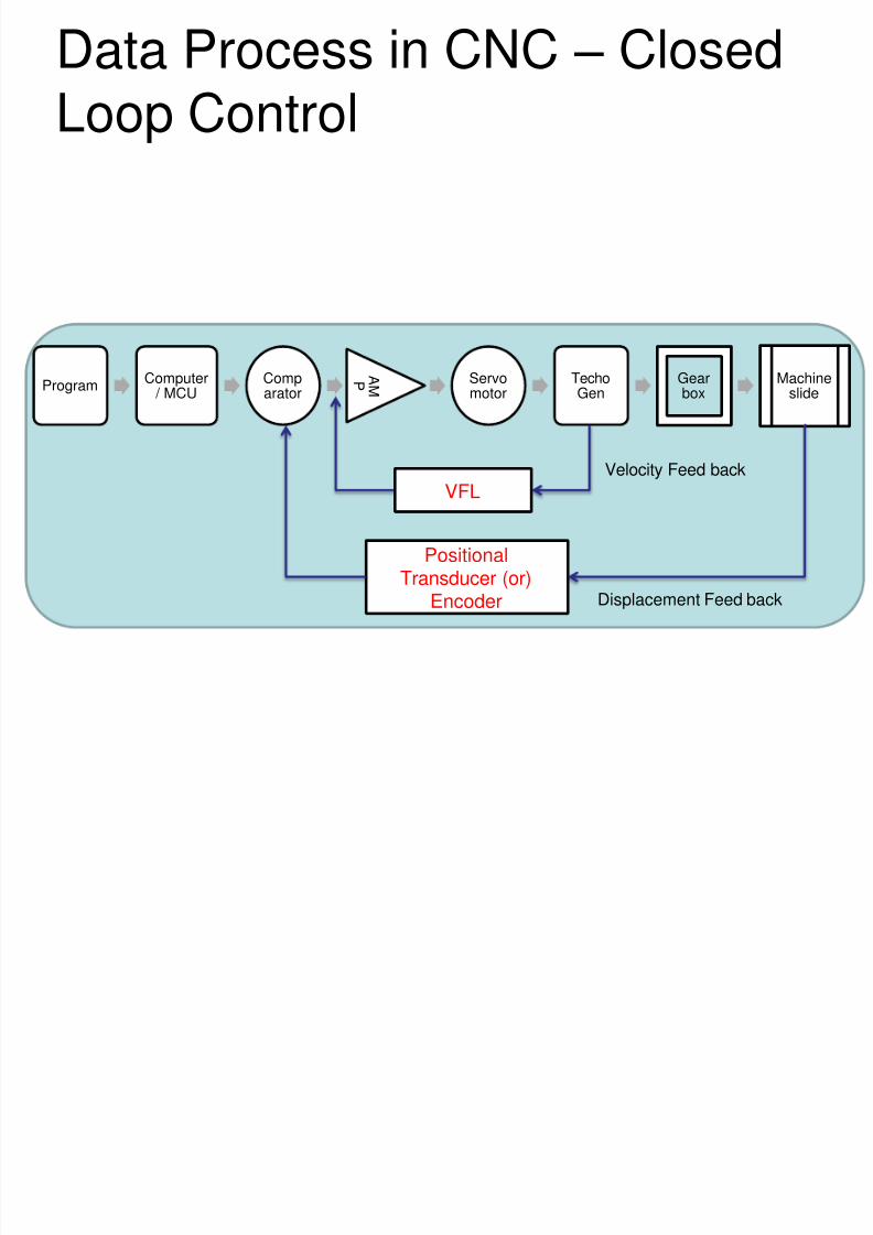
ProgramComputer / MCU
Comparator
A MP Servo
motorTechoGen
Gearbox
Machineslide
Data Process in CNC – ClosedLoop Control
PositionalTransducer (or)
Encoder
VFL
Displacement Feed back
Velocity Feed back
NC SYSTEM
8/4/2019 CNC TECHNOLOG
http://slidepdf.com/reader/full/cnc-technolog 30/115
NC SYSTEMClassification of NC system
CLOSED LOOP SYSTEM
TAPEREADER
COMPARATORUNIT
PROCESSINGUNIT
CONTROLLING UNITEg: Hydraulic Ram
MACHINE TOOL SLIDEDISPLACEMENT
MESAURINGDEVICE
C o m m a n d S i g n a l
S a y a d i s t a n c e o f 1 0 0
m m Signal
Representing
ActualPositionEg; 99.85 mm
Convertedcommand
ConvertedCommand(100-99.85)
Deviation in
processedFromEg: 0.15Converted intoHydraulic form
8/4/2019 CNC TECHNOLOG
http://slidepdf.com/reader/full/cnc-technolog 31/115
8/4/2019 CNC TECHNOLOG
http://slidepdf.com/reader/full/cnc-technolog 32/115
NC SYSTEM
Classification of NC system
Based on Motion control system features, the NC system as follows
• Point-to-Point system
• Straight cut or Straight line system
• Continuous path or Contouring system
8/4/2019 CNC TECHNOLOG
http://slidepdf.com/reader/full/cnc-technolog 33/115
NC SYSTEM
Classification of NC system
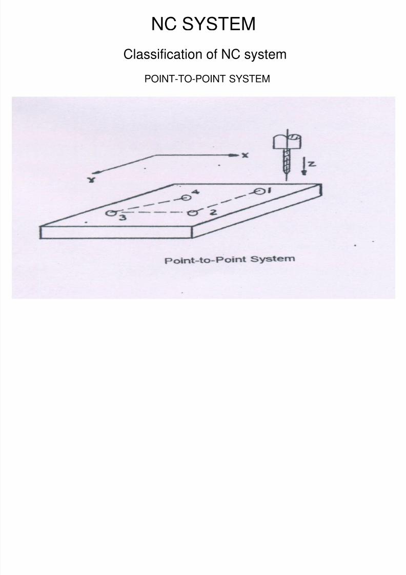
POINT-TO-POINT SYSTEM – Positioning System
• Point-to-Point system the machine performs machining operations at
specific positions and does not affect the work piece while moving from one
point to the next.
• In PTP, the importance is given to move the work piece/tool to a predefined
location with respect to other, when the location reached, the operation
performed
• Tool/Table movements are rapid traverse
• Path of movement is irregular
Example: In a drilling machine where co-ordinates are positioned by the system
8/4/2019 CNC TECHNOLOG
http://slidepdf.com/reader/full/cnc-technolog 34/115
NC SYSTEM
Classification of NC system
POINT-TO-POINT SYSTEM
8/4/2019 CNC TECHNOLOG
http://slidepdf.com/reader/full/cnc-technolog 35/115
Point to Point (P – type)
P1
P2
P3
P0
Y
X
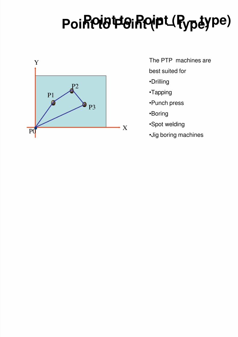
Point to Point (P – type)
The PTP machines are
best suited for
•Drilling•Tapping
•Punch press
•Boring
•Spot welding•Jig boring machines
8/4/2019 CNC TECHNOLOG
http://slidepdf.com/reader/full/cnc-technolog 36/115
NC SYSTEM
Classification of NC system
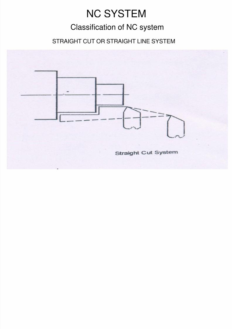
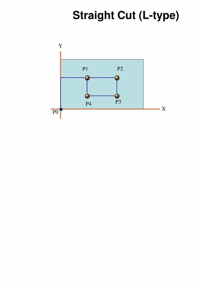
STRAIGHT CUT OR STRAIGHT LINE SYSTEM
• In this system, the cutting tool moves parallel to X axis (or) Y axis during
the machining operations at a controlled rate
• This is an extension of Point-to-Point control system when the provision of
straight cut milling capability.
Example
Face Milling.
Pocket milling
Stepped Turning on Lathe
Boring, etc..,
8/4/2019 CNC TECHNOLOG
http://slidepdf.com/reader/full/cnc-technolog 37/115
NC SYSTEM
Classification of NC system
STRAIGHT CUT OR STRAIGHT LINE SYSTEM
8/4/2019 CNC TECHNOLOG
http://slidepdf.com/reader/full/cnc-technolog 38/115
Straight Cut (L-type)
P1 P2
P3
P0
Y
XP4
8/4/2019 CNC TECHNOLOG
http://slidepdf.com/reader/full/cnc-technolog 39/115
NC SYSTEM
Classification of NC system
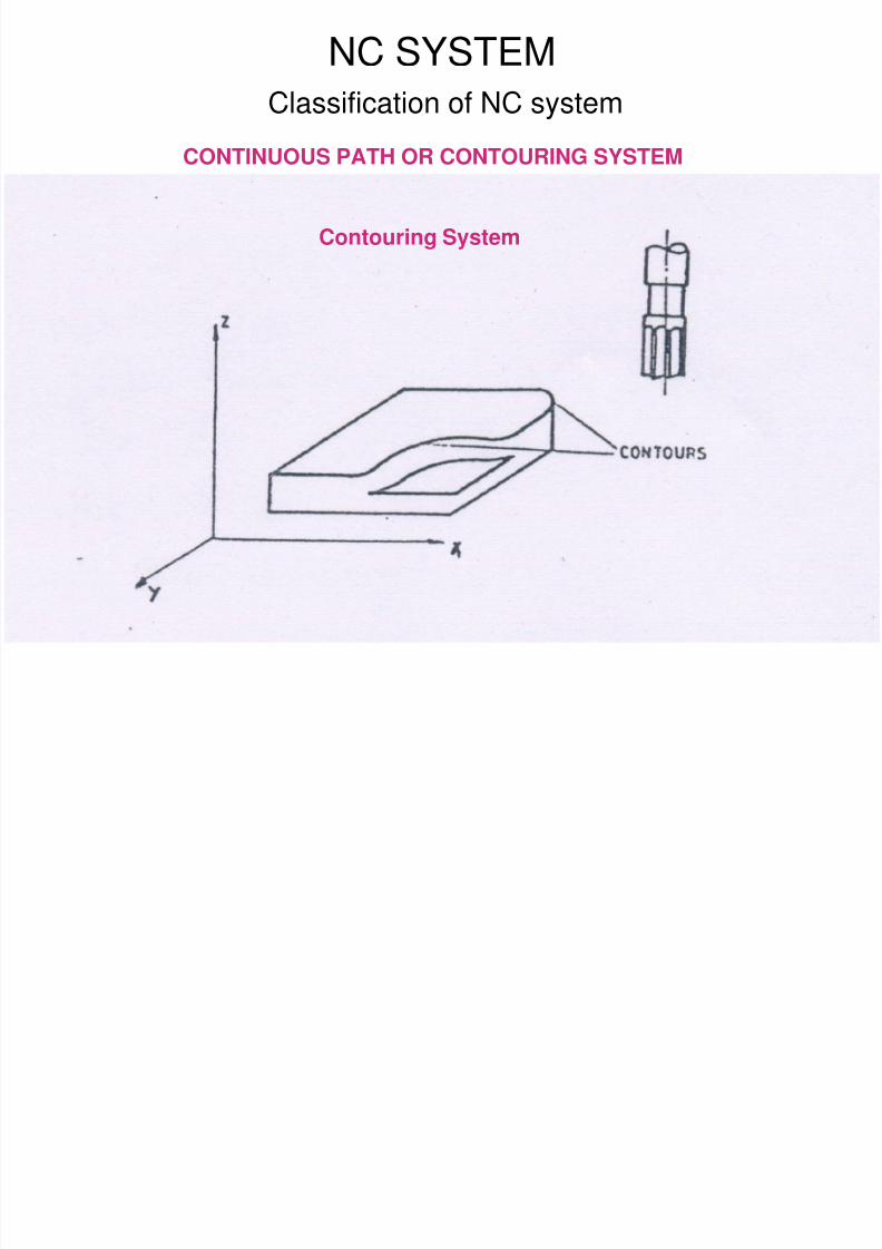
CONTINUOUS PATH OR CONTOURING SYSTEM
• This calls for continuous, simultaneous and co-coordinated or in other
words interrelated motion of the tool and work piece along differentcoordinate axes.
• This enables profiles, contours and curved surfaces to be machined.
• This means that the position of several slides must be controlled on the
machine tool so that their relative position and velocities must be
established at every point and continuously, throughout the entire operation.
8/4/2019 CNC TECHNOLOG
http://slidepdf.com/reader/full/cnc-technolog 40/115
CONTINUOUS PATH OR CONTOURING SYSTEM
Classification of NC system
NC SYSTEM
Contouring System
8/4/2019 CNC TECHNOLOG
http://slidepdf.com/reader/full/cnc-technolog 41/115
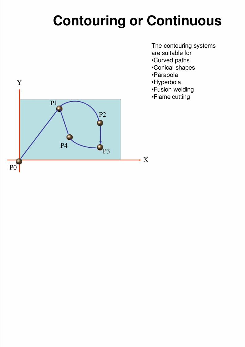
Contouring or Continuous
P1
P2
P3
P0
Y
X
P4
The contouring systemsare suitable for•Curved paths•Conical shapes•Parabola•Hyperbola
•Fusion welding•Flame cutting
8/4/2019 CNC TECHNOLOG
http://slidepdf.com/reader/full/cnc-technolog 42/115
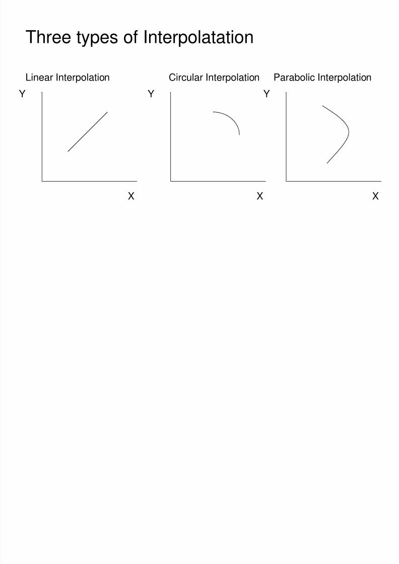
Three types of Interpolatation
Linear Interpolation Circular Interpolation Parabolic Interpolation
X
Y
X
Y
X
Y
8/4/2019 CNC TECHNOLOG
http://slidepdf.com/reader/full/cnc-technolog 43/115
APPLICATION OF CNC MACHINES
1. METAL CUTTING MACHINES
CNC Milling
CNC Turning
CNC Drilling / Boring
CNC Gear Cutting
CNC Grinding
8/4/2019 CNC TECHNOLOG
http://slidepdf.com/reader/full/cnc-technolog 44/115
APPLICATION OF CNC MACHINES
2. METAL FORMING MACHINE
• Press Tools
• Injection / Blow Moulding Machines
• Die Casting Machines
• Tube Bending
8/4/2019 CNC TECHNOLOG
http://slidepdf.com/reader/full/cnc-technolog 45/115
APPLICATION OF CNC MACHINES
3. NON CONVENTIONAL MACHINING PROCESS
• EDM Sinking and EDM Wire-cut machines.
• Plasma Arc cutting machines.
• Electron Beam machining.
• Laser Beam machining.
• Ion Beam machining.
• Ultrasonic machining etc.
8/4/2019 CNC TECHNOLOG
http://slidepdf.com/reader/full/cnc-technolog 46/115
APPLICATION OF CNC MACHINES
4. Welding machines (TIG, MIG, Submerged Arc welding etc.)
5. Inspection and Quality Control systems (CMM,LMM).
6. Assembly, Testing and Despatch equipments.
7. Tool and work handling systems
S O CO O S
8/4/2019 CNC TECHNOLOG
http://slidepdf.com/reader/full/cnc-technolog 47/115
SERVO CONTROLLERS
8/4/2019 CNC TECHNOLOG
http://slidepdf.com/reader/full/cnc-technolog 48/115
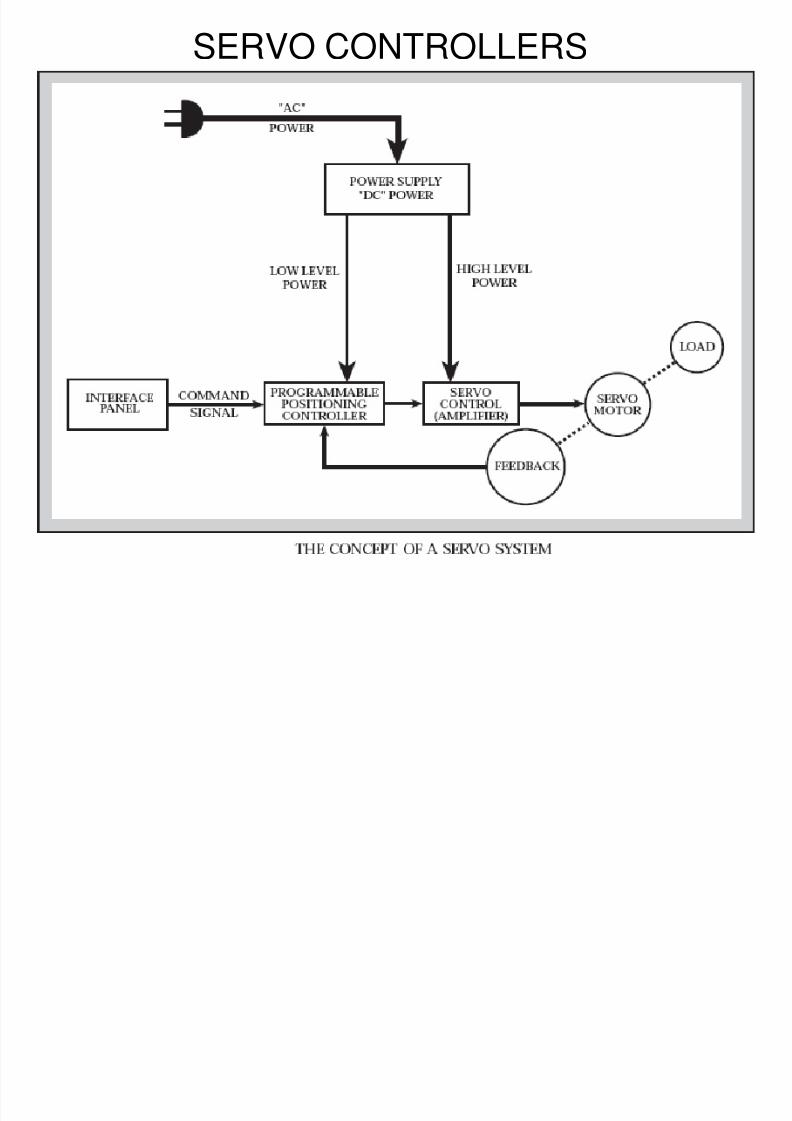
The function of a servo can be described as follows.
• A command signal which is issued from the user'sinterface panel comes into servo’s
“POSITIONING CONTROLLER”.
• The positioning controller is the device which storesinformation about various jobs or tasks.
• It has been programmed to activate the motor/load,.Change speed/position.
• The signal then passes into the servo control or“amplifier” section.
The servo control takes this low powerlevel signal and increases, or , amplifies, the power up toappropriate levels to actually result in movements ofservo motor/load.
These low power level signals must be amplified:
8/4/2019 CNC TECHNOLOG
http://slidepdf.com/reader/full/cnc-technolog 49/115
• These low power level signals must be amplified:
Higher voltage levels are needed to rotate the servo motor atappropriate higher speeds and high current levels are required toprovide torque to move heavier loads.
• This power is supplied to servo control (amplifier) from the “power supply” which simply converts AC power into the required DC level.
• It also supplies any low level voltage required for operation of integratedcircuits.
• As the power is applied onto the servo motor ,the load begins to
move…Speed and position changes. As the load moves, so does some
other “device” move.
This other “device” is either a
tachometer,resolver or encoder (providing the signal which
is “sent back” to the controller). This “feedback” signal isinforming the positioning controller whether the motor isdoing the proper job.
8/4/2019 CNC TECHNOLOG
http://slidepdf.com/reader/full/cnc-technolog 50/115
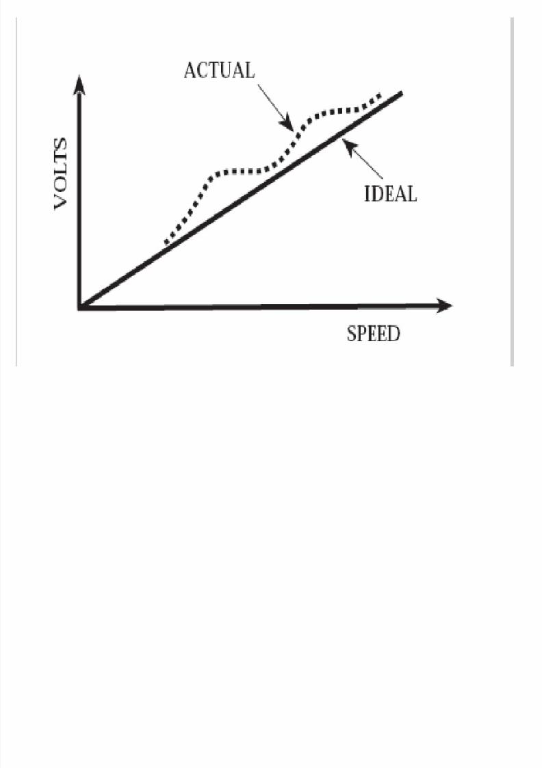
The positioning controller looks at this feed back signal anddetermines if the load is being moved properly by the servomotor; and, if not , then the controller makes appropriate
corrections.For example
• Assume the command signal has to drive the load of 1000rpm
• For some reason it is actually rotating at 900 rpm.
• The feed back signal will inform the controller that the speed is900 rpm.
• The controller then compares the commanded signal (desired )of 1000rpm and the feed back signals (actual speed) of 900rpmand notes an error.
• The controller then outputs a signal equals the command signal,i.e there is no error.
• Servo system is defined that it consists of several devices whichcontrol or regulate speed/position of a load
Encoder
8/4/2019 CNC TECHNOLOG
http://slidepdf.com/reader/full/cnc-technolog 51/115
Encoder• The transducer that is connected directly to the rotor or the lead screw is
the simplest arrangement requiring no additional gearing (manyservomotors come with integral rotary encoders).
Optical Rotary Encoder
• An optical rotary encoder converts the rotary motioninto a sequence of digital pulses.
• The pulses are counted to convert u-absolute or
incremental position measurement.• The encoder generally come in two forms, absolute
encoder and incremental encoder.
• The absolute encoder provides the exact rotational position ofthe shaft whereas the incremental encoder gives the relative position of
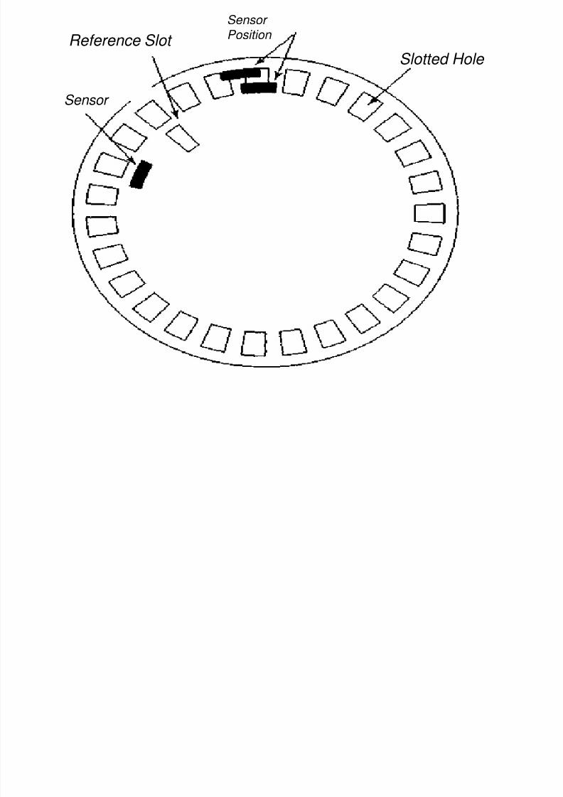
the shaft in terms of digital pulses.• The optical encoder consists of a disc (as shown in Fig) with a number of
accurately etched equidistant lines or slots along the periphery.
• The encoder disc is attached to the shaft of the machine whose
rotary position needs to be measured.
Sensor
8/4/2019 CNC TECHNOLOG
http://slidepdf.com/reader/full/cnc-technolog 52/115
Position Reference Slot
Sensor
Slotted Hole
8/4/2019 CNC TECHNOLOG
http://slidepdf.com/reader/full/cnc-technolog 53/115
• The disc is placed between a light source (generally infrared LED) and a light measuring device (photo diode).
• When the disc rotates the lines are interrupted and thelight measuring device counts the number of times thelight is interrupted.
• By a careful counting and necessary calculations it ispossible to know the position traversed by the shaft.
8/4/2019 CNC TECHNOLOG
http://slidepdf.com/reader/full/cnc-technolog 54/115
Retrofitting
Replacing the conventional leadscrews with ball-bearing
screws.
Adding stepper motors ( for open loop control), or dc
servomotors and feedback devices (for closed-lop control); the
drive is added to each controlled axis.
If control is applied three are more axes, the total expense
becomes considerable and the project is not always cost
effective.
8/4/2019 CNC TECHNOLOG
http://slidepdf.com/reader/full/cnc-technolog 55/115
SALIENT FEATURES OF CNC MACHINES
• High rigidity.
• High stiffness to weight ratio.
• Thermal stability.
• Good clamping characteristics.
1. MACHINE STRUCTURE
8/4/2019 CNC TECHNOLOG
http://slidepdf.com/reader/full/cnc-technolog 56/115
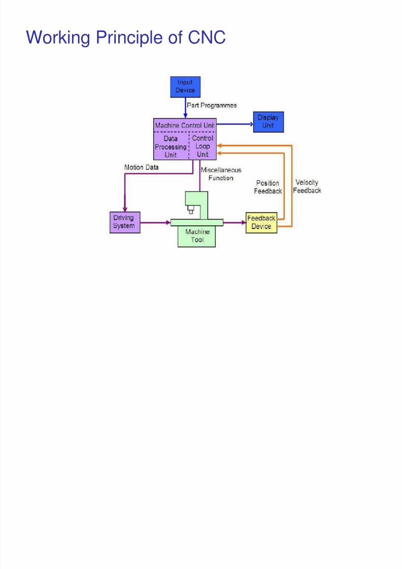
Working Principle of CNC

8/4/2019 CNC TECHNOLOG
http://slidepdf.com/reader/full/cnc-technolog 57/115
8/4/2019 CNC TECHNOLOG
http://slidepdf.com/reader/full/cnc-technolog 58/115
SALIENT FEATURES OF CNC MACHINES
2.FEED DRIVE
• Slides are actuated by precision pre-loaded re-circulating ball screw and nut
mechanism driven by servomotors and an electronic controller
• Speed motor have a constant Torque• Non-moving slides are held by powerful servo locks and are not
mechanically clamped.
8/4/2019 CNC TECHNOLOG
http://slidepdf.com/reader/full/cnc-technolog 59/115
Requirements of CNC Feed drive
• The CNC feed drive should have constant torque to overcomefrictional and working forces
• Should provide variable speed with a speed range of 0.1 rpm to2000 rpm without waviness
• Able to position the tools with the smallest increment of 1-2micrometer
• Low electrical and mechanical time constants
• High torque to weight ratio
• High torque for quick response
• Totally enclosed design-safe & maintenance conditions
8/4/2019 CNC TECHNOLOG
http://slidepdf.com/reader/full/cnc-technolog 60/115
Commonly used Feed drives/Drive motors
• DC Silicon Controlled Rectifier (SCR)
• Pulse Width Modulated (PWM) drive
• DC servo motor
– High performance motor
– Start and stop must be made quickly and accurately
– Light weight
– Low inertia armatures of DC servo motor respond quickly to theexcitation voltage changes
• Brush less DC Servo motor
• AC servo motor
• Stepper Motor
• Variable frequency AV drive or Linear motors
8/4/2019 CNC TECHNOLOG
http://slidepdf.com/reader/full/cnc-technolog 61/115
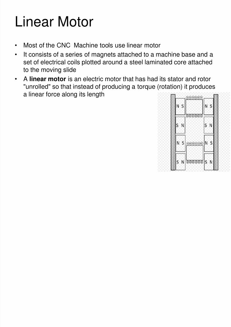
Linear Motor
• Most of the CNC Machine tools use linear motor
• It consists of a series of magnets attached to a machine base and aset of electrical coils plotted around a steel laminated core attachedto the moving slide
• A linear motor is an electric motor that has had its stator and rotor"unrolled" so that instead of producing a torque (rotation) it producesa linear force along its length
8/4/2019 CNC TECHNOLOG
http://slidepdf.com/reader/full/cnc-technolog 62/115
SALIENT FEATURES OF CNC MACHINES
2. SLIDE WAYS
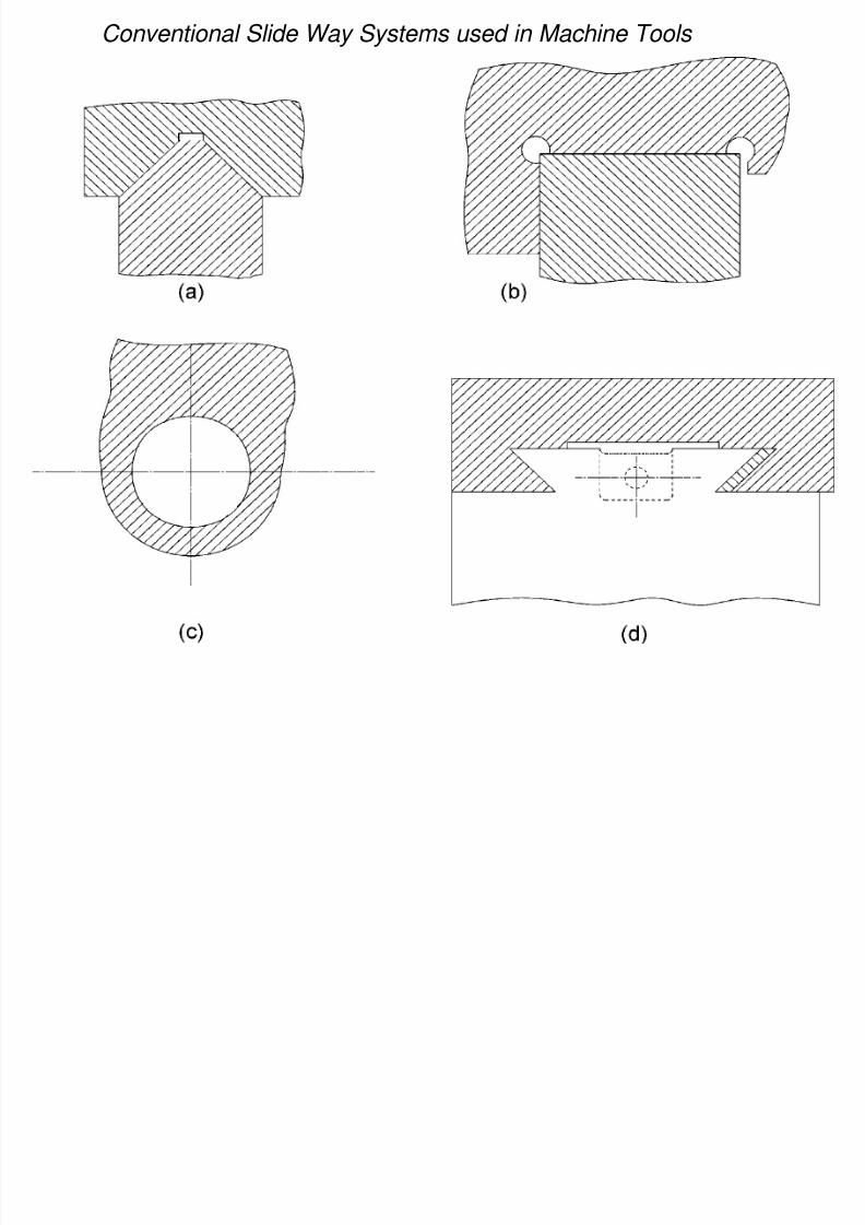
• In conventional machines, there is direct metal to metal contact between
the slide way and the moving slides which results in very slow movements
and machine utilization.
• The conventional type of arrangement does not meet the requirement of
CNC Machines
• The demand on slide ways is much more in CNC machines because of the
rapid movements and higher machine utilization.
Conventional Slide Way Systems used in Machine Tools
8/4/2019 CNC TECHNOLOG
http://slidepdf.com/reader/full/cnc-technolog 63/115
8/4/2019 CNC TECHNOLOG
http://slidepdf.com/reader/full/cnc-technolog 64/115
SLIDE WAYS
The design of slide way in a CNC machine should,
Reduce friction.
Reduce wear.
Satisfy the requirements of the movement of the slides.
Improve smoothness of the drive
To meet this requirements CNC machine slide ways, the techniques used
include hydrostatic, linear bearings with balls, rollers or needles and surface
coatings
8/4/2019 CNC TECHNOLOG
http://slidepdf.com/reader/full/cnc-technolog 65/115
SLIDE WAYS
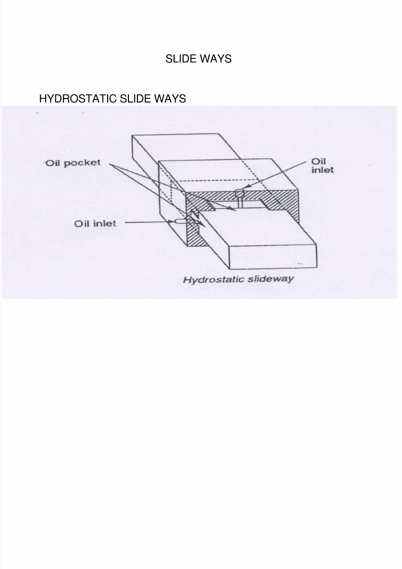
In this slide ways air or oil is pumped into small pockets or cavities
machined into the carriage or slides which are in contact with the slide way.
The pressure of the fluid gradually reduces to atmospheric pressure as it seeps
out from the pockets, through the gap between the slide and slide ways.
The hydrostatic slide way provides almost a frictionless condition for the
movement of the slide.
HYDROSTATIC SLIDE WAYS

8/4/2019 CNC TECHNOLOG
http://slidepdf.com/reader/full/cnc-technolog 66/115
SLIDE WAYS
For efficient operation it is very important that the fluid and slide ways are kept
clean.
The hydraulic slide ways need a very large surface area to provide adequate
support.
HYDROSTATIC SLIDE WAYS
8/4/2019 CNC TECHNOLOG
http://slidepdf.com/reader/full/cnc-technolog 67/115
SLIDE WAYS
HYDROSTATIC SLIDE WAYS
8/4/2019 CNC TECHNOLOG
http://slidepdf.com/reader/full/cnc-technolog 68/115
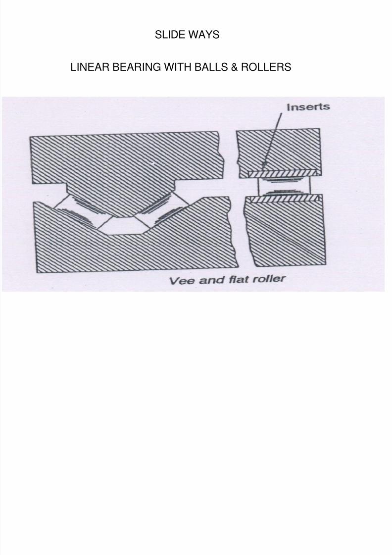
SLIDE WAYS
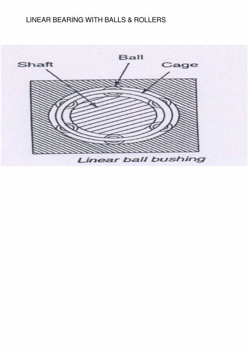
LINEAR BEARING WITH BALLS & ROLLERS
The sliding friction due to direct metal contact between the slide and slide
ways is replaced with rolling friction by the use of antifriction ball or roller
bearing.
These are designed to run along precision ground shafts and offer
frictionless movement over varying strock of length with high linear
precision.
8/4/2019 CNC TECHNOLOG
http://slidepdf.com/reader/full/cnc-technolog 69/115
SLIDE WAYS
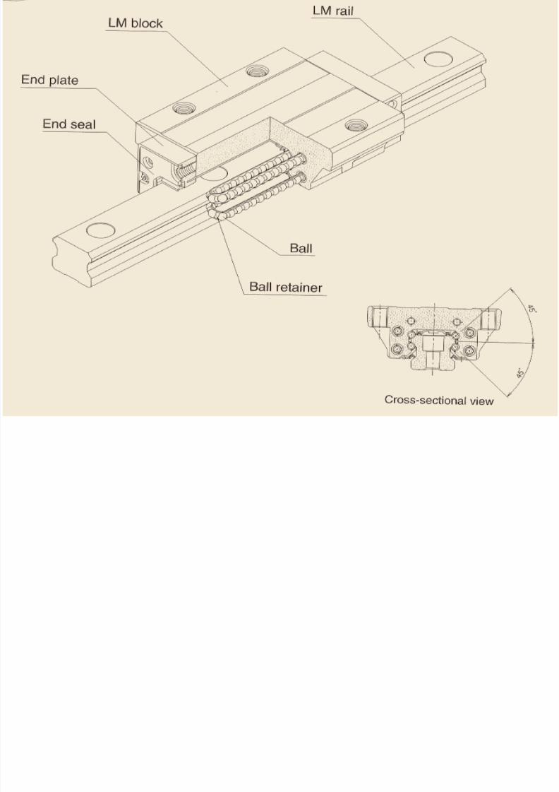
LINEAR BEARING WITH BALLS & ROLLERS
For movement along a flat plane, re-circulating linear roller bearings are used.
The main characteristic of the linear roller bearing is that there is a continuous
roller circulation, which allows unlimited linear movement.
A linear bearing (also called TYCHOWAY), consists of hardened & precision
ground supporting elements and a number of cylindrical rollers
8/4/2019 CNC TECHNOLOG
http://slidepdf.com/reader/full/cnc-technolog 70/115
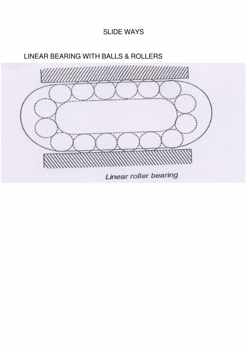
SLIDE WAYS
LINEAR BEARING WITH BALLS & ROLLERS
The rollers are guided between the shoulders of the supporting elements with
very close tolerances.
The guiding element prevents the rollers from falling out and sliding againsteach other.
The guiding elements assist in smooth return of the rollers to the loading zone.
8/4/2019 CNC TECHNOLOG
http://slidepdf.com/reader/full/cnc-technolog 71/115
SLIDE WAYS
LINEAR BEARING WITH BALLS & ROLLERS
8/4/2019 CNC TECHNOLOG
http://slidepdf.com/reader/full/cnc-technolog 72/115
SLIDE WAYS
LINEAR BEARING WITH BALLS & ROLLERS
8/4/2019 CNC TECHNOLOG
http://slidepdf.com/reader/full/cnc-technolog 73/115
8/4/2019 CNC TECHNOLOG
http://slidepdf.com/reader/full/cnc-technolog 74/115
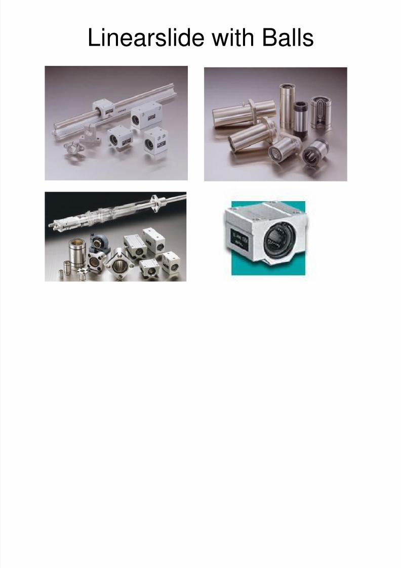
Linearslide with Balls
8/4/2019 CNC TECHNOLOG
http://slidepdf.com/reader/full/cnc-technolog 75/115
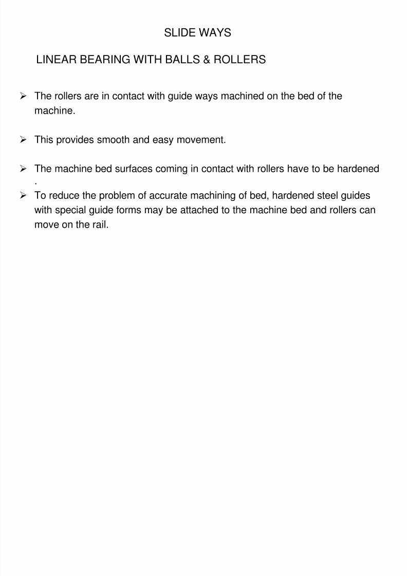
SLIDE WAYS
LINEAR BEARING WITH BALLS & ROLLERS
The rollers are in contact with guide ways machined on the bed of the
machine.
This provides smooth and easy movement.
The machine bed surfaces coming in contact with rollers have to be hardened.
To reduce the problem of accurate machining of bed, hardened steel guides
with special guide forms may be attached to the machine bed and rollers can
move on the rail.
8/4/2019 CNC TECHNOLOG
http://slidepdf.com/reader/full/cnc-technolog 76/115
LINEAR BEARING WITH BALLS & ROLLERS
8/4/2019 CNC TECHNOLOG
http://slidepdf.com/reader/full/cnc-technolog 77/115
LINEAR BEARING WITH BALLS & ROLLERS
The linear roller bearing can be mounted horizontally for load carryingapplications such as machine tool table.
They can be mounted vertically to provide support, guidance andmotion for vertical elements of the machine tool.
Vee and flat roller arrangement can also be used to provide frictionlesslinear movement.
SURFACE COATINGS

8/4/2019 CNC TECHNOLOG
http://slidepdf.com/reader/full/cnc-technolog 78/115
SURFACE COATINGS
The guiding surfaces of the machines are coated with lowfriction materials such as POLYTETRAFLUROETHYLENE
(PTFE), or replaceable strips of low friction material are used.
When the strips wear to such an extent that the alignment is inerror, these can be replaced.
ELEMENTS OF MOTION TRANSMISSION
8/4/2019 CNC TECHNOLOG
http://slidepdf.com/reader/full/cnc-technolog 79/115
The rotary motion from the drive motor needs to be converted into linearmotion to move the various axes of the machine.
In conventional machine square thread is used.
The conventional machines use lead screw for motion transmission purpose.
Due to high friction between the lead screw & nut results in poor transmission
efficiency and back lash.
In CNC machines with use of re-circulating ball screw and nut arrangementthese problems have been overcome.
Here again, the approach is to replace sliding friction by rolling friction.
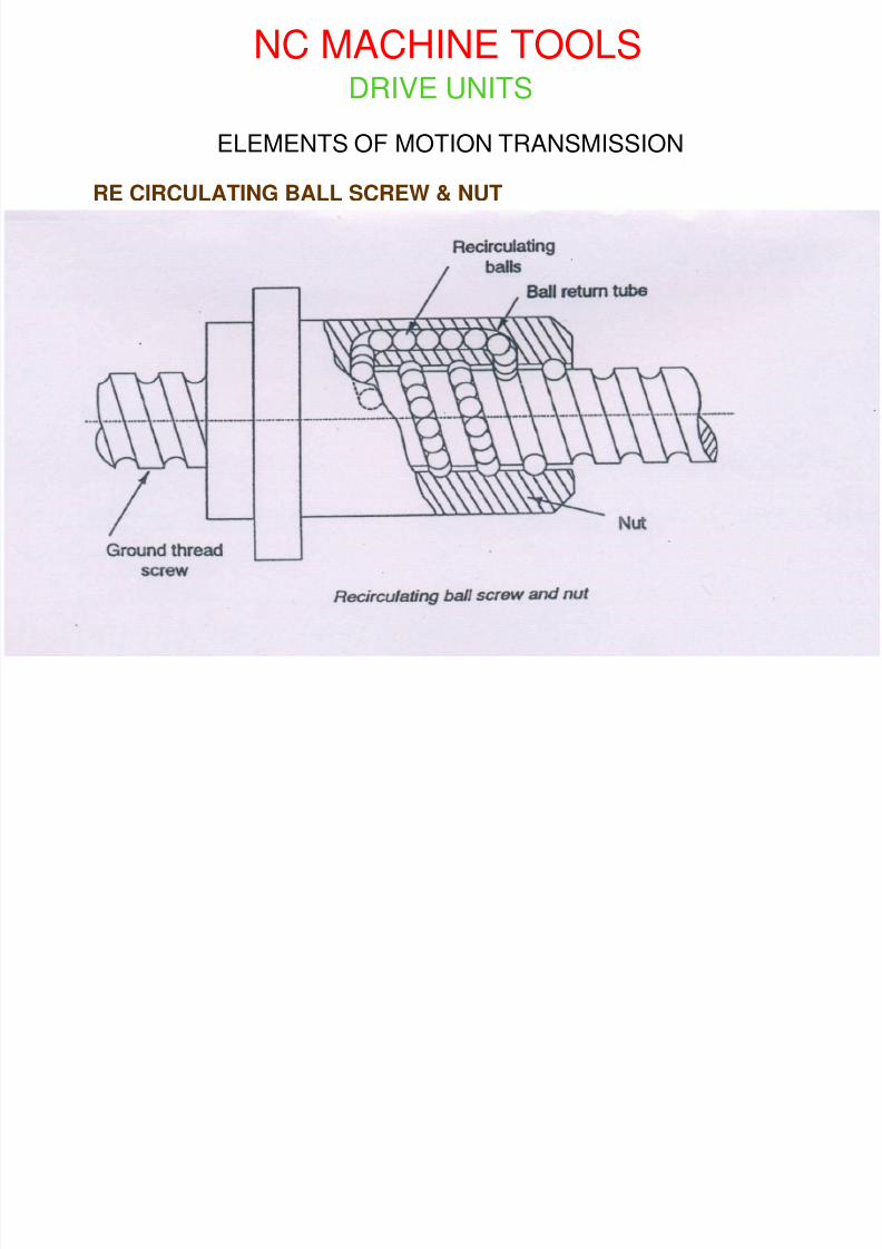
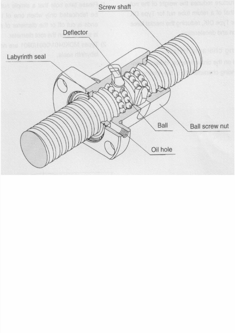
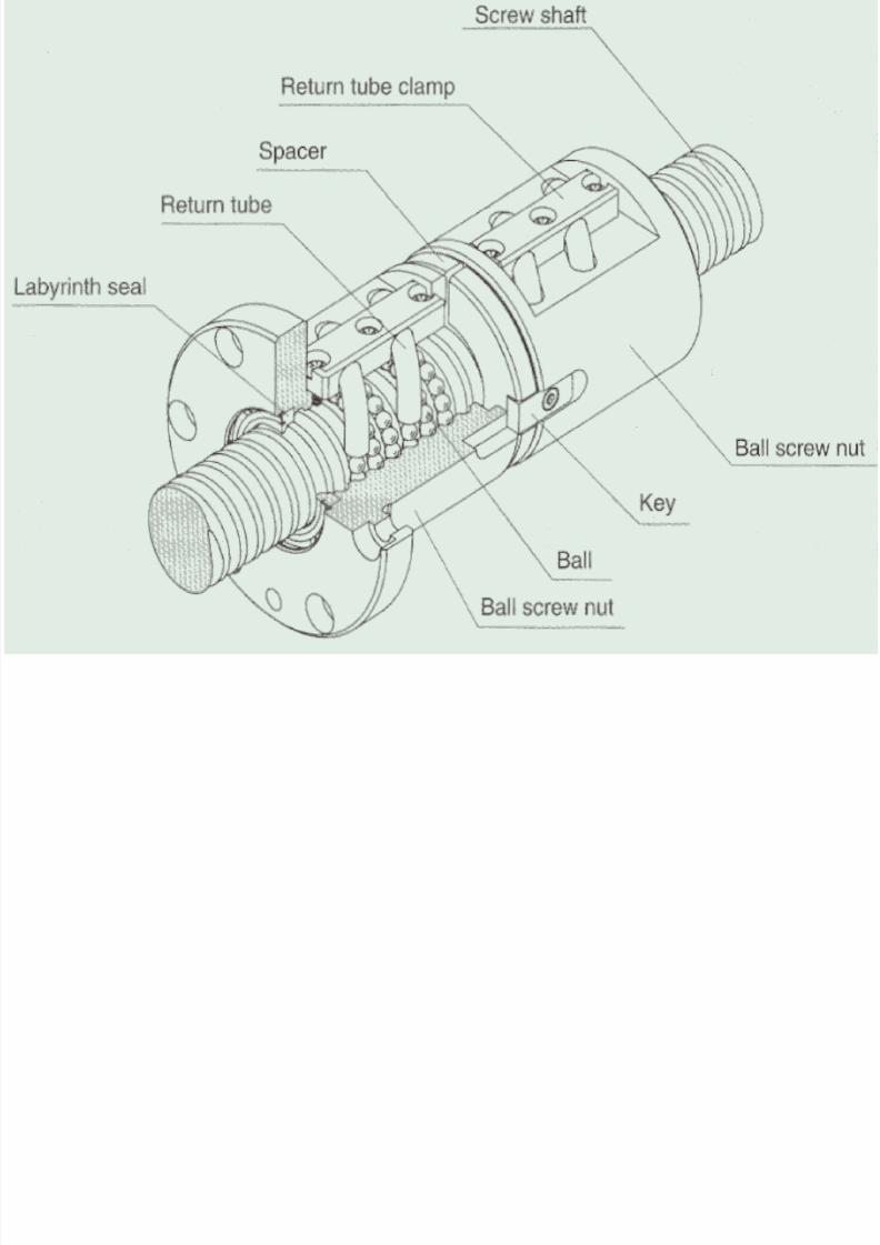
RE CIRCULATING BALL SCREW & NUT
NC MACHINE TOOLS
8/4/2019 CNC TECHNOLOG
http://slidepdf.com/reader/full/cnc-technolog 80/115
DRIVE UNITS
ELEMENTS OF MOTION TRANSMISSION
RE CIRCULATING BALL SCREW & NUT
8/4/2019 CNC TECHNOLOG
http://slidepdf.com/reader/full/cnc-technolog 81/115
8/4/2019 CNC TECHNOLOG
http://slidepdf.com/reader/full/cnc-technolog 82/115
8/4/2019 CNC TECHNOLOG
http://slidepdf.com/reader/full/cnc-technolog 83/115
ELEMENTS OF MOTION TRANSMISSION
The connection between the screw and the nut is through an endless stream
of re-circulating steel balls.
The screw thread is a hardened and ground ball race in which the steel balls,
in the nut, circulate.
The balls rotate between the screw and the nut and at the same point the balls
are returned to start of the thread in the nut.
The rigidity of the drive system & positioning accuracy can be further improved
by pre-loading the nut assembly.
RE CIRCULATING BALL SCREW & NUT
8/4/2019 CNC TECHNOLOG
http://slidepdf.com/reader/full/cnc-technolog 84/115
ELEMENTS OF MOTION TRANSMISSION
HIGH EFFICIENCY:
As compared to conventional lead screw the efficiency of ball screw & nut
assembly is very high (over 90%).The power requirement is also less due to
reduce friction.
RE CIRCULATING BALL SCREW & NUT ADVANTAGES
8/4/2019 CNC TECHNOLOG
http://slidepdf.com/reader/full/cnc-technolog 85/115
ELEMENTS OF MOTION TRANSMISSION
REVERSIBILITY:
The ball screw & nut assembly is reversible which makesit possible to back drive the unit .
i.e. by applying axial force to either nut or screw, theunconstrained member can be made to rotate.
RE CIRCULATING BALL SCREW & NUT ADVANTAGES
8/4/2019 CNC TECHNOLOG
http://slidepdf.com/reader/full/cnc-technolog 86/115
ELEMENTS OF MOTION TRANSMISSION
WEAR & LIFE:
The re-circulating rollers reduce wear to a minimum and the ball screw. Hence
longer life with out loss of accuracy.
RE CIRCULATING BALL SCREW & NUT ADVANTAGES
ELEMENTS OF MOTION TRANSMISSION
8/4/2019 CNC TECHNOLOG
http://slidepdf.com/reader/full/cnc-technolog 87/115
ELEMENTS OF MOTION TRANSMISSION
NO STICK SLIP:
Stick slip is a phenomenon, which occurs when small movement between two
lubricated elements are required.
The lubricating medium tries to cause the mating elements to stick to each
other to resist motion and results in a jerky motion as the mating elements try
to stick and then slip during their relative movement.
Since the sliding metal-to-metal contact is substituted by rolling contact, the
stick-up phenomenon is eliminated in the ball screw and nut assembly.
RE CIRCULATING BALL SCREW & NUT ADVANTAGES
B ll L d S
8/4/2019 CNC TECHNOLOG
http://slidepdf.com/reader/full/cnc-technolog 88/115
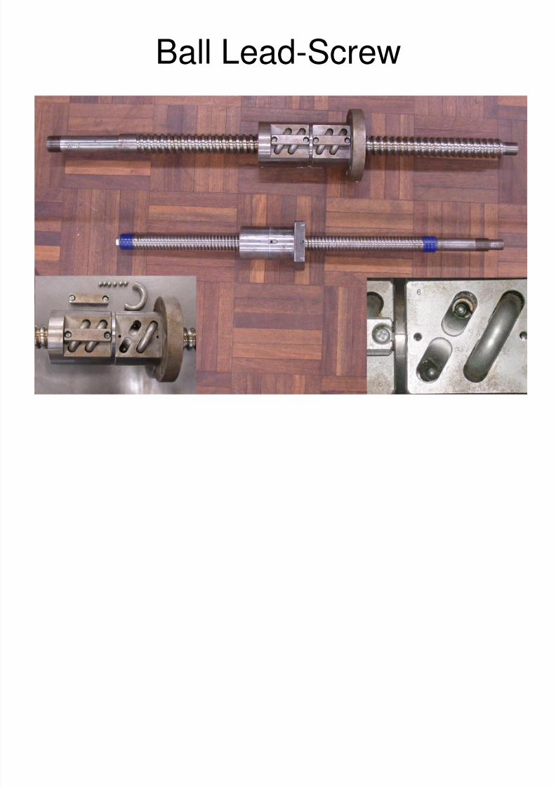
Ball Lead-Screw
8/4/2019 CNC TECHNOLOG
http://slidepdf.com/reader/full/cnc-technolog 89/115
SALIENT FEATURES OF CNC MACHINES
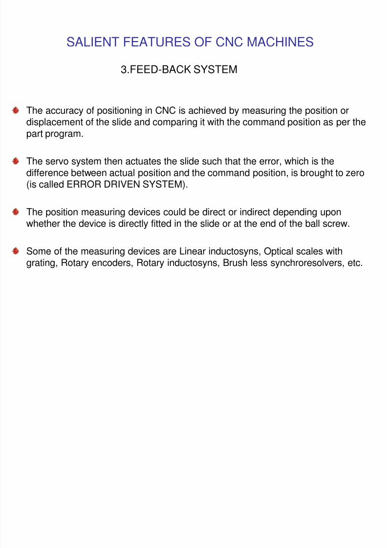
3.FEED-BACK SYSTEM
The accuracy of positioning in CNC is achieved by measuring the position ordisplacement of the slide and comparing it with the command position as per thepart program.
The servo system then actuates the slide such that the error, which is thedifference between actual position and the command position, is brought to zero(is called ERROR DRIVEN SYSTEM).
The position measuring devices could be direct or indirect depending uponwhether the device is directly fitted in the slide or at the end of the ball screw.
Some of the measuring devices are Linear inductosyns, Optical scales withgrating, Rotary encoders, Rotary inductosyns, Brush less synchroresolvers, etc.
FEED BACK DEVICES
8/4/2019 CNC TECHNOLOG
http://slidepdf.com/reader/full/cnc-technolog 90/115
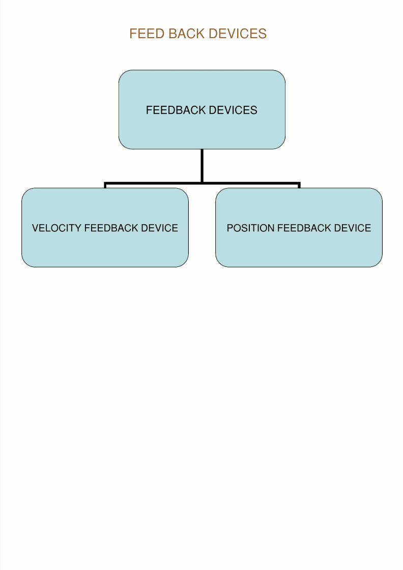
FEED BACK DEVICES
FEEDBACK DEVICES
VELOCITY FEEDBACK DEVICE POSITION FEEDBACK DEVICE
FEED BACK DEVICES:Two types of feed back is required
8/4/2019 CNC TECHNOLOG
http://slidepdf.com/reader/full/cnc-technolog 91/115
Two types of feed back is required.
1) Velocity feed back
2) Positional feed back
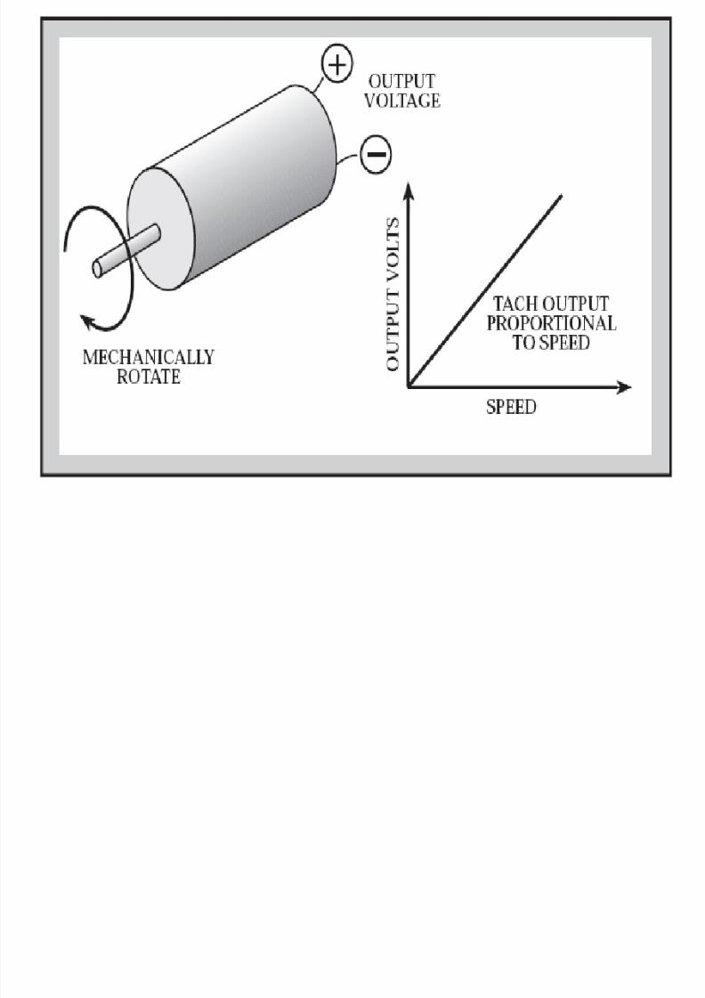
Velocity feed back: It will measure the spindle rpm.
Tachogenerator is used.
It will generate voltage in proportional to the speed.
The tachogenerator is normally built in the servomotor cases
and is directly fitted on the servomotor shaft.
The o/p voltage is compared & monitored the spindle speed.
Rotary encoders are also used to provide feedback for velocity control.
8/4/2019 CNC TECHNOLOG
http://slidepdf.com/reader/full/cnc-technolog 92/115
8/4/2019 CNC TECHNOLOG
http://slidepdf.com/reader/full/cnc-technolog 93/115
FEED BACK DEVICES
8/4/2019 CNC TECHNOLOG
http://slidepdf.com/reader/full/cnc-technolog 94/115
POSITION FEED BACK DEVICE
Measurements from cutting edge are not possible due to the presence of
chips, coolant, holding devices and in some case, due to the component
geometry itself
The positional feed back is provided by measuring the slide movements with
measuring devices
The position measuring devices are either rotary or linear measuring
transducers.
POSITION FEED BACK DEVICE
8/4/2019 CNC TECHNOLOG
http://slidepdf.com/reader/full/cnc-technolog 95/115
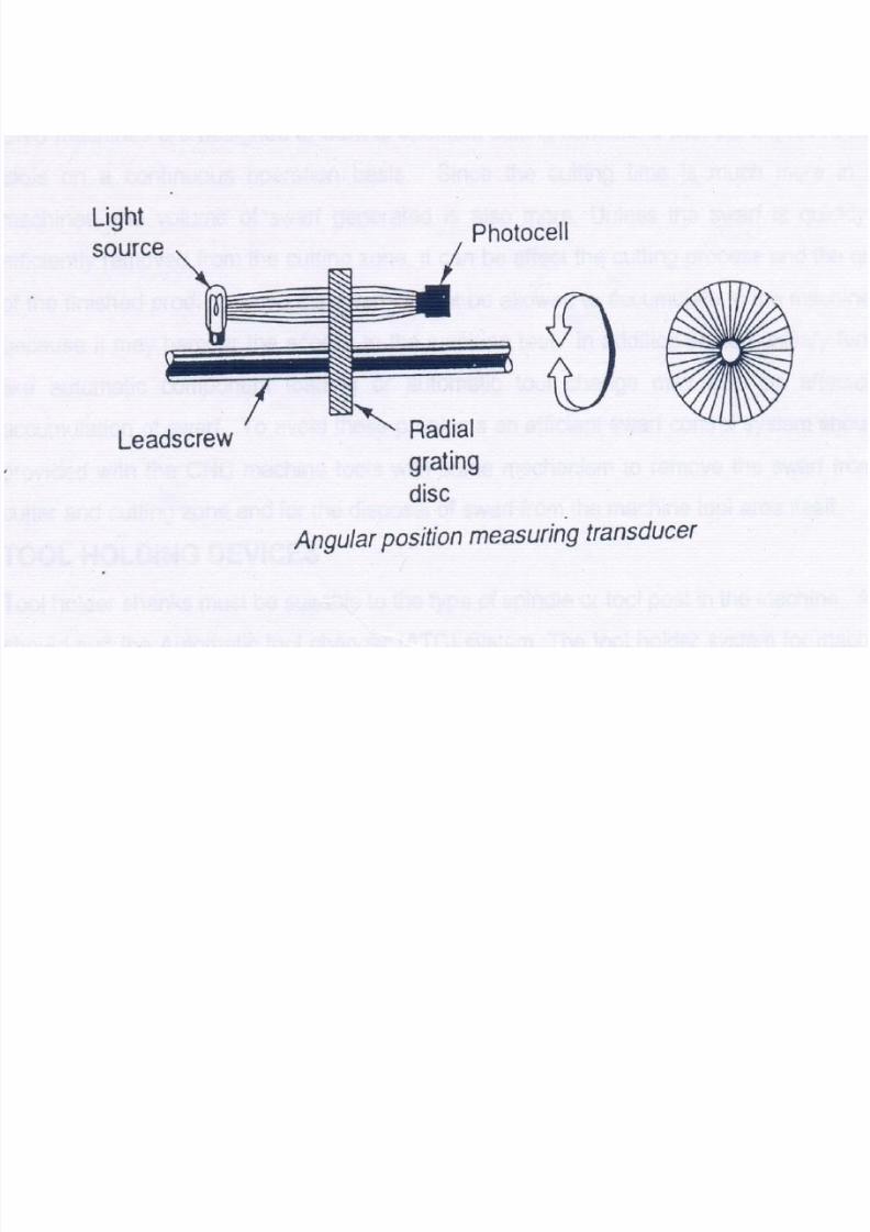
POSITION FEED BACK DEVICE
Angular position measuring transducers operates by measuring the angular
speed of a rotating element, normally of a lead screw, from the known value
of the lead screw, movement of the work table or machine slide is calculated
by control system
Angular position measuring transducers operate on the photo electricprinciple
The transducer consists of a disc fitted on the axis of lead screw
The disc is made up of uniform alternate transparent and opaque areas
A light source is fitted on one side of the disc and photocell on the other side
When the disc rotates with rotation of the lead screw, the photocell will sensethe light and dark areas alternatively
As the dark area of the disc is gradually uncovered the light intensity falling
on the photocell goes on increasing until it reaches the maximum when the
transparent part of the disc comes in from the light source
ROTARY OR ANGULAR POSITION MEASURING TRANSDUCERS
POSITION FEED BACK DEVICE
8/4/2019 CNC TECHNOLOG
http://slidepdf.com/reader/full/cnc-technolog 96/115
As the disc continuous to rotate the dark area starts to reduce the lightintensity falling on the photocell which will gradually reduces to zero when thedark area comes between the photocell and light source
The photocell gives output voltage based on the intensity of light falling on it
and the out put from photocell resembles a sine-wave, which is converted in tosquare shaped pulses to make it useful for control purposes
The number of output pulses is then counted
As the output from the photo cell is related to the rate at which the transparentareas of the disc comes in front of the light source, the speed of the lead
screw is calculated from the known number of lines engraved on the rotatingdisc
The displacement of the slide is then calculated from the lead of the leadscrew
ROTARY OR ANGULAR POSITION MEASURING TRANSDUCERS
8/4/2019 CNC TECHNOLOG
http://slidepdf.com/reader/full/cnc-technolog 97/115
FEED BACK DEVICES
8/4/2019 CNC TECHNOLOG
http://slidepdf.com/reader/full/cnc-technolog 98/115
POSITION FEED BACK DEVICE
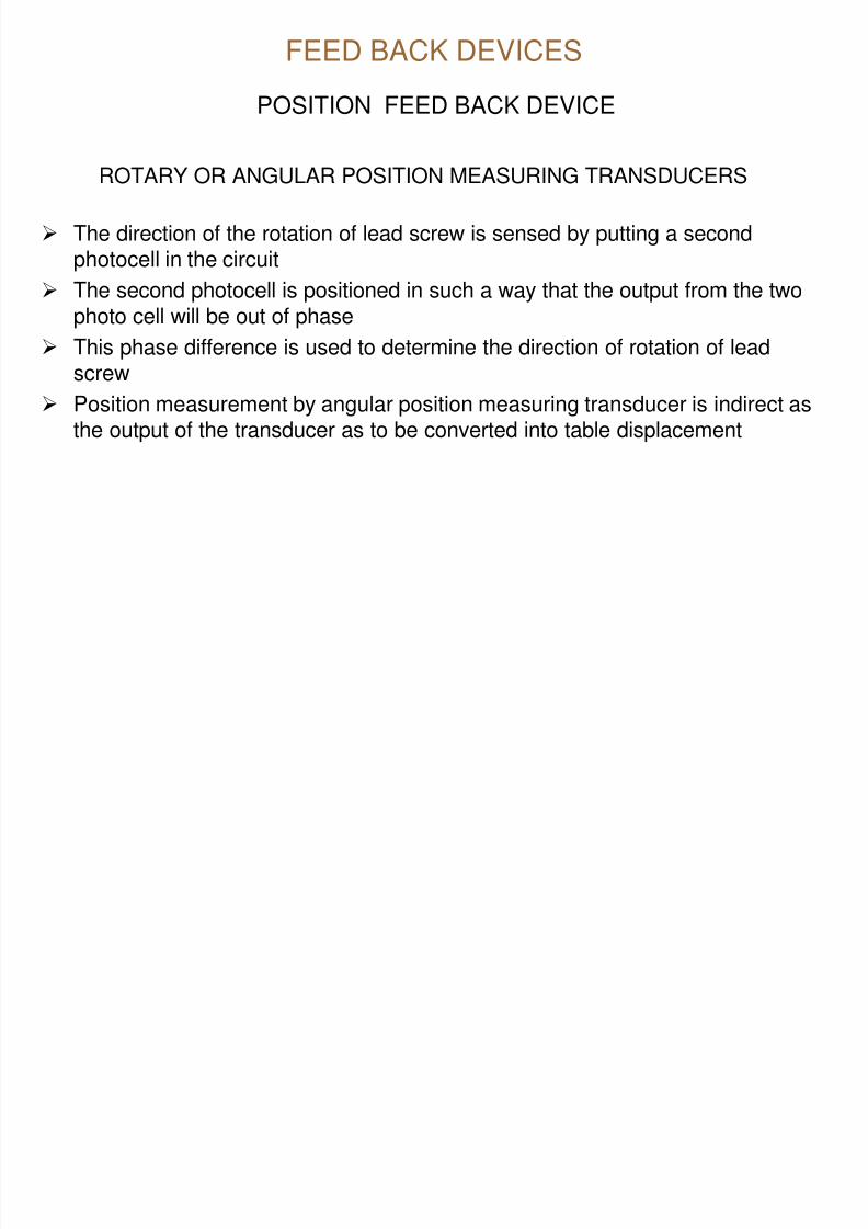
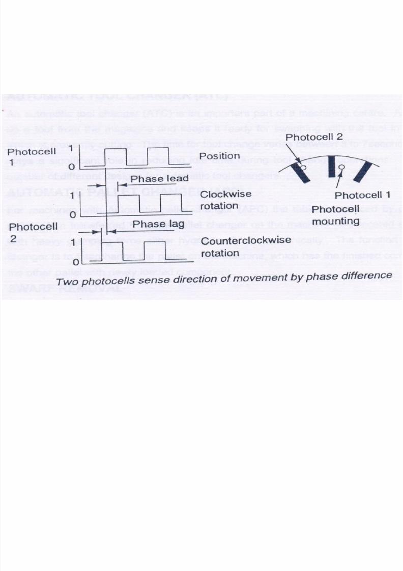
ROTARY OR ANGULAR POSITION MEASURING TRANSDUCERS
The direction of the rotation of lead screw is sensed by putting a secondphotocell in the circuit
The second photocell is positioned in such a way that the output from the two
photo cell will be out of phase This phase difference is used to determine the direction of rotation of lead
screw
Position measurement by angular position measuring transducer is indirect asthe output of the transducer as to be converted into table displacement
8/4/2019 CNC TECHNOLOG
http://slidepdf.com/reader/full/cnc-technolog 99/115
8/4/2019 CNC TECHNOLOG
http://slidepdf.com/reader/full/cnc-technolog 100/115
FEED BACK DEVICES
POSITION FEED BACK DEVICE
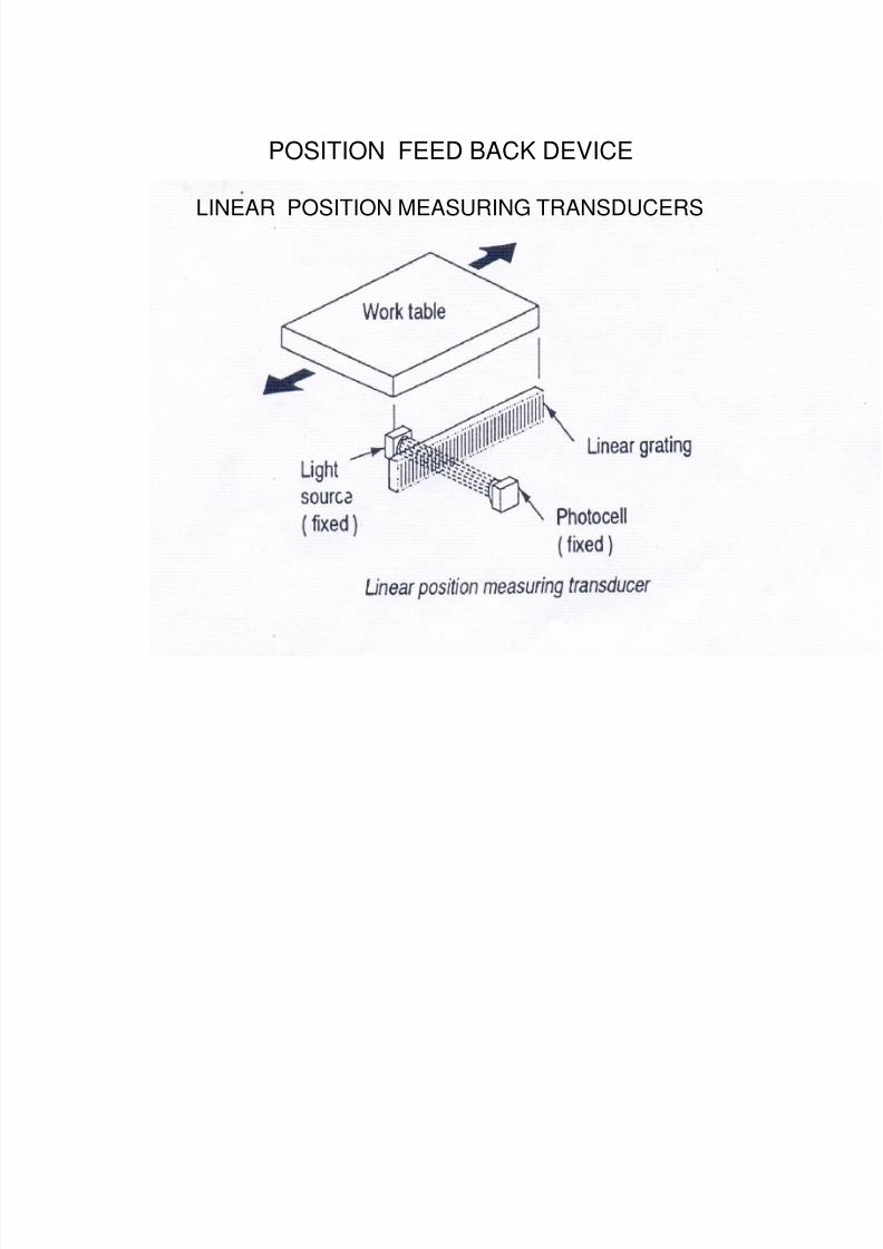
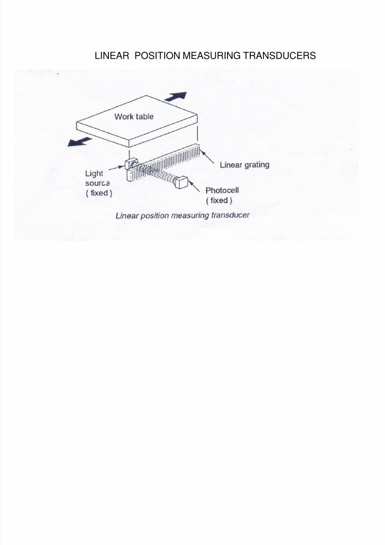
LINEAR POSITION MEASURING TRANSDUCERS
Linear position measuring transducer also operate on the photoelectric
principle.
The linear measuring system measures the displacement of the machine liedfrom a fixed datum.
8/4/2019 CNC TECHNOLOG
http://slidepdf.com/reader/full/cnc-technolog 101/115
POSITION FEED BACK DEVICE
LINEAR POSITION MEASURING TRANSDUCERS
8/4/2019 CNC TECHNOLOG
http://slidepdf.com/reader/full/cnc-technolog 102/115
• A linear measuring system consists of a precision linear scale engraved
with closed space alternate transparent and opaque parallel lines as oneunit and a photocell and light source as the second unit.
• One of the units is fixed on the stationary element of the machine tool and
the other unit is fixed to the moving worktable.
• A pulse is generated by the photocell as it is exposed to light source
through the transparent areas of the linear scale.
FEED BACK DEVICES
POSITION FEED BACK DEVICE
LINEAR POSITION MEASURING TRANSDUCERS
8/4/2019 CNC TECHNOLOG
http://slidepdf.com/reader/full/cnc-technolog 103/115
• A pulse is generated by the photocell as it is exposed to light source
through the transparent areas of the linear scale.
• From the known number of the engraved lines per unit length on the linear
scale and by counting the pulses, the displacement of the work table can be
established.
FEED BACK DEVICES
POSITION FEED BACK DEVICE
LINEAR POSITION MEASURING TRANSDUCERS
8/4/2019 CNC TECHNOLOG
http://slidepdf.com/reader/full/cnc-technolog 104/115
• As in the case of rotary transducers, a second photocell is used to detect
the direction of movement.
• The linear system may have either a glass cell in which case light passes
through the transparent area or a ss scale , the light is reflected from thetransparent areas.
FEED BACK DEVICES
POSITION FEED BACK DEVICE
LINEAR POSITION MEASURING TRANSDUCERS
.
8/4/2019 CNC TECHNOLOG
http://slidepdf.com/reader/full/cnc-technolog 105/115
LINEAR POSITION MEASURING TRANSDUCERS

8/4/2019 CNC TECHNOLOG
http://slidepdf.com/reader/full/cnc-technolog 106/115
SALIENT FEATURES OF CNC MACHINES
8/4/2019 CNC TECHNOLOG
http://slidepdf.com/reader/full/cnc-technolog 107/115
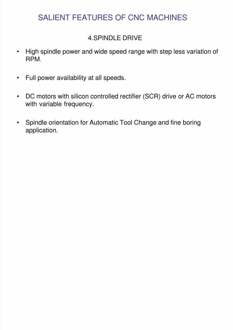
4.SPINDLE DRIVE
• High spindle power and wide speed range with step less variation ofRPM.
• Full power availability at all speeds.
• DC motors with silicon controlled rectifier (SCR) drive or AC motorswith variable frequency.
• Spindle orientation for Automatic Tool Change and fine boringapplication.
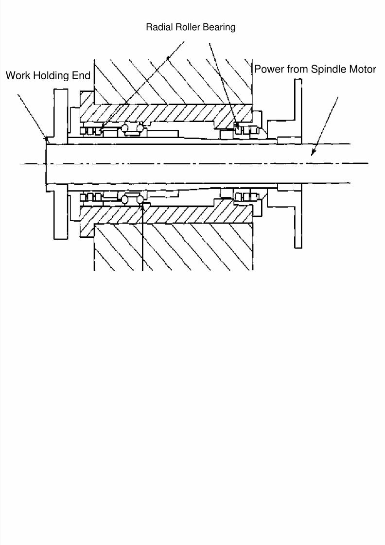
Radial Roller Bearing
8/4/2019 CNC TECHNOLOG
http://slidepdf.com/reader/full/cnc-technolog 108/115
Work Holding EndPower from Spindle Motor
8/4/2019 CNC TECHNOLOG
http://slidepdf.com/reader/full/cnc-technolog 109/115
8/4/2019 CNC TECHNOLOG
http://slidepdf.com/reader/full/cnc-technolog 110/115
SALIENT FEATURES OF CNC MACHINES
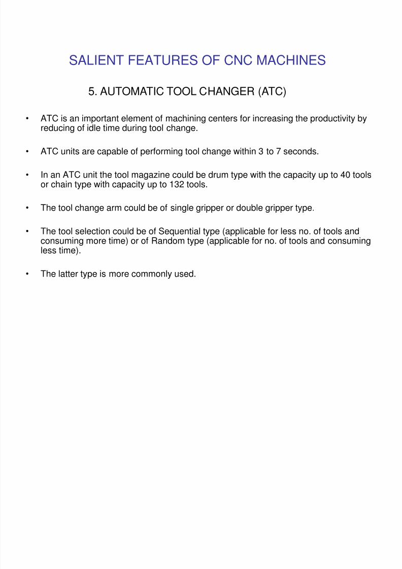
5. AUTOMATIC TOOL CHANGER (ATC)
• ATC is an important element of machining centers for increasing the productivity byreducing of idle time during tool change.
• ATC units are capable of performing tool change within 3 to 7 seconds.
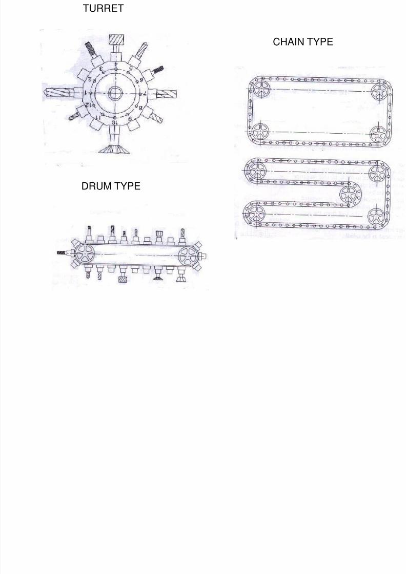
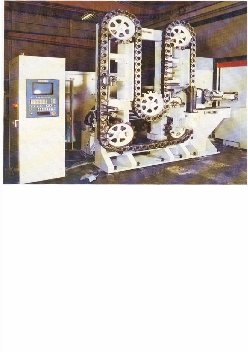
• In an ATC unit the tool magazine could be drum type with the capacity up to 40 toolsor chain type with capacity up to 132 tools.
• The tool change arm could be of single gripper or double gripper type.
• The tool selection could be of Sequential type (applicable for less no. of tools andconsuming more time) or of Random type (applicable for no. of tools and consumingless time).
• The latter type is more commonly used.
CHAIN TYPE
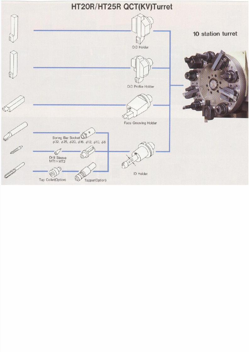
TURRET
8/4/2019 CNC TECHNOLOG
http://slidepdf.com/reader/full/cnc-technolog 111/115
CHAIN TYPE
DRUM TYPE
8/4/2019 CNC TECHNOLOG
http://slidepdf.com/reader/full/cnc-technolog 112/115
8/4/2019 CNC TECHNOLOG
http://slidepdf.com/reader/full/cnc-technolog 113/115
8/4/2019 CNC TECHNOLOG
http://slidepdf.com/reader/full/cnc-technolog 114/115
SALIENT FEATURES OF CNC MACHINES
6. AUTOMATIC PALLET CHANGER (APC)
• APC aids in increase of productivity by reducing the job set up time.
• Function is to interchange the pallet on the machine that has finishedcomponent and the other pallet with the newly loaded component.
• Setting up of the work piece is done away from the machine tool. Thusimproves machine utilization time.
• The pallet changer gets located on the machine and clamped with heavy
clamping force either hydraulically or mechanically.
• APCs could be of dual pallet type or multiple pallet pool type.
INTRODUCTION TO CNC MACHINES
8/4/2019 CNC TECHNOLOG
http://slidepdf.com/reader/full/cnc-technolog 115/115
SALIENT FEATURES OF CNC MACHINES
Some other features of CNCs Thermal stabilization of headstock, feed drive elements and machine
structural elements by re-circulated refrigerated oil.
Axial calibration for all fixed mechanical elements.
Lost motion compensation for all fixed mechanical elements.
Usage of Torch trigger probes for post process metrology purposes, Toolcondition monitoring, Tool measurement and setting of tool offsets andthermal error compensation.
Centralized lubrication of slides, etc., controlled by timer or software.
Coolant systems of either flood type or myst type.
Chip conveyors for collection and disposal of chips. Auto diagnostic to aid maintenance and service personnel.