Embed Size (px)
Citation preview

1
September 9, 2013Kawasaki Heavy Industries, Ltd.
Suguru Oyama
CO2-FREE HYDROGEN SUPPLY CHAIN PROJECT AND RISK ASSESSMENT FOR THE SAFETY DESIGN

Contents
1.1.1.1.CO2-Free Hydrogen supply Chain
2.2.2.2.Establishment of Hydrogen Safety System
3.3.3.3.HAZOP and Risk Assessment for Hydrogen
Liquefaction Plant
4.4.4.4.Safety Design for Liquid Hydrogen Carrier
2

3
1.CO2-Free Hydrogen Supply Chain

Overview of commercial-scale HESC
H2 Loading base
H2 Production plantfrom brown coal
H2 Pipe line
Melbourne
H2 Carrier
Carbon-Net Project
4

Brown coal gasification plantBrown coal gasification plant
Hydrogenrefining plant
Hydrogenrefining plant
Brown coal::::Hydrogen::::
CO2 ::::
14,200 t/day770 t/day
13,300 t/day
4,700,000 t/year246,000 t/year
4,400,000 t/year
Hydrogen Production Plant
5

Hydrogen liquefaction: Capacity:770 t/day
Hydrogen storage facility: 50,000 m3 x 5 tanks
Hydrogen Loading Base
6

Liquefied Hydrogen Carrier
Ship type: Pressure built-upNumbers of ship: 2H2 carrier size: 160,000 m3/shipBoil off Rate (BOR): 0.2% / day
Length: 315 mWidth: 56 mDepth: 28 mRequired sea depth: 11 m
Annual delivery Qty: 238,500 ton/year-H2Service speed: 16 kts Voyage days: 12.6 days/one way
7

CIF cost≒≒≒≒ 30 yen/Nm3
Production
Liquefaction
Loading base
Brown coal
Carrier
CO2 storage
9%
11%
33%
10%
8%
29%
Loading quantity: 238,500 t/year
Delivered hydrogen quantity225,400 t/year
FCV (Fuel Cell Vehicle) : 3 million
Hydrogen power plant : 650 MW
Delivered hydrogen cost (CIF Japan)
8

Result cost is more competitive than wind and solar.
Evaluation of power generation use in Japan
Feed-in Tarifffrom July, 2012
for 20 years
Nuclear LNG Coal OilHydrogen derived from Brown Coal
Wind Solar
Power generation cost [ yen/kWh]
9

The Next Stage
• It was found that commercial-scale HESC is technically and economically feasible and will deliver significant benefits both to Australia and Japan.
• However, before commercialization, technical demonstration, safety verification and demonstration of stable operation to potential investors are necessary with pilot-scale HESC.
Then as a next stage, conceptual design of pilot-scaleHESC with preliminary costs has been conducted.
****HESC::::Hydrogen Energy Supply Chain10

PLANT SYSTEM CAPACITY NUMBER REFERENCE
Brown coal Gasification Plant and Hydrogen Refining Plant
5.5t/d-H2 1set
Annual Hydrogen Production Capacity
2,660 tonElectrytic Hydrogen Production Plant 2.9t/d-H2 1set
Hydrogen Liquefaction Plant 4.2t/d-H2 1set
Hydrogen Gas TurbineGeneration Plant 4.2t/d-H2 1set -
Hydrogen Storage Facility 3,400m3 1set Annual Cargo Capacity873 ton
Hydrogen Carrier 2,500 m3 1set
Pilot Scale Chain Main Specifications
11

Brown CoalBrown CoalBrown CoalBrown Coal
Gasification PlantGasification PlantGasification PlantGasification Plant
HydrogenHydrogenHydrogenHydrogen
Purification PlantPurification PlantPurification PlantPurification Plant
Water Water Water Water
ElectrolElectrolElectrolElectrolyyyysis Plantsis Plantsis Plantsis Plant
HydrogenHydrogenHydrogenHydrogen
Liquefaction PlantLiquefaction PlantLiquefaction PlantLiquefaction Plant
Lorry Lorry Lorry Lorry
StationStationStationStation
Lorry StationLorry StationLorry StationLorry Station
LiquidLiquidLiquidLiquid HydrogenHydrogenHydrogenHydrogen
Storage TankStorage TankStorage TankStorage Tank
Vent StackVent StackVent StackVent Stack
BOGBOGBOGBOG HeaterHeaterHeaterHeater
Pilot Scale Chain Hydrogen Production PlantHydrogen Loading BaseLiquefied Hydrogen Carrier
12

1) 2030 Commercialization2) 2025 Demonstration Operation Start3) 2017 Pilot Chain Operation Start4) ~2013 Establishment of Technology, Funding and Consortium
13
Schedule of Development

2. Establishment of Hydrogen Safety System
SafetyTechnology
Development
Global SafetyStandard
Safety Management
System
SocialAcceptance
SafetyTechnology
Development
Global SafetyStandard
Safety Management
System
SocialAcceptance
14

Establishment of International Safety Standards( Liquefied Hydrogen Carrier )
Minimum/Special Requirementsof
IGC Code
Basic Designof
Liquid Hydrogen Carrier
Safety Evaluationof
Hydrogen Carrier
Incorporation of selective countermeasures
Hazard identificationand risk assessment, using HAZID and FMEA method
Amendment of minimum/special requirements in IGC Code
Proposal for IGC Code and International standard
Conclusion of bilateral agreementbetween Japan and Australia, Certification of IMO
****HAZID::::HAZard Identification
****FMEA::::Failure Modes and Effects Analysis
Minimum/Special Requirementsof
IGC Code
Basic Designof
Liquid Hydrogen Carrier
Safety Evaluationof
Hydrogen Carrier
Safety Evaluationof
Hydrogen Carrier
Incorporation of selective countermeasures
Hazard identificationand risk assessment, using HAZID and FMEA method
Amendment of minimum/special requirements in IGC Code
Proposal for IGC Code and International standard
Conclusion of bilateral agreementbetween Japan and Australia, Certification of IMO
****HAZID::::HAZard Identification
****FMEA::::Failure Modes and Effects Analysis
15

3,000m3
(2.1x10⁵kg)540m3 (3.8x10⁴kg)
50,000m3
(3.5x10⁶kg)
3,000m3
(2.1x10⁵kg)540m3 (3.8x10⁴kg)
50,000m3
(3.5x10⁶kg)
Safety Distance from LH2 Tank
16Reference: K. Verfondern, Figure 6-5 Safety Distances, Safety Considerations on Liquid Hydrogen, p53-54, 2008.
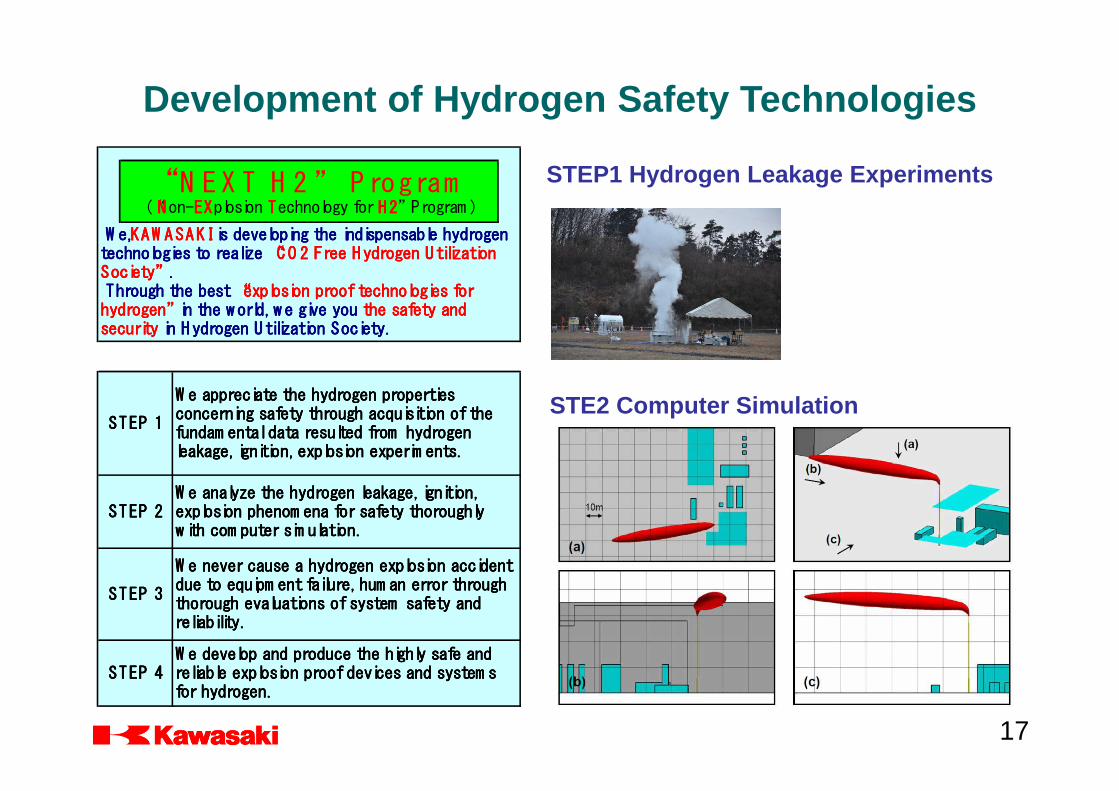
Development of Hydrogen Safety Technologies
“N E X T H 2 ” P rogram
(“NNNNon-EXEXEXEXplosion TTTTechnology for H2H2H2H2” Program )
W e,W e,W e,W e,KAW ASAKIKAW ASAKIKAW ASAKIKAW ASAKI is developing the indispensable hydrogen is developing the indispensable hydrogen is developing the indispensable hydrogen is developing the indispensable hydrogen
technologies to realize technologies to realize technologies to realize technologies to realize “CO 2 Free Hydrogen Utilization“CO 2 Free Hydrogen Utilization“CO 2 Free Hydrogen Utilization“CO 2 Free Hydrogen Utilization
Society”Society”Society”Society” . . . .
Through the bestThrough the bestThrough the bestThrough the best “explosion proof technologies for “explosion proof technologies for “explosion proof technologies for “explosion proof technologies for
hydrogen”hydrogen”hydrogen”hydrogen” in the w orld, w e give you in the w orld, w e give you in the w orld, w e give you in the w orld, w e give you the safety andthe safety andthe safety andthe safety and
securitysecuritysecuritysecurity in Hydrogen Utilization Society.in Hydrogen Utilization Society.in Hydrogen Utilization Society.in Hydrogen Utilization Society.
STEP 1STEP 1STEP 1STEP 1
STEP 2STEP 2STEP 2STEP 2
STEP 3STEP 3STEP 3STEP 3
STEP 4STEP 4STEP 4STEP 4
W e appreciate the hydrogen propertiesW e appreciate the hydrogen propertiesW e appreciate the hydrogen propertiesW e appreciate the hydrogen properties
concerning safety through acquisition of theconcerning safety through acquisition of theconcerning safety through acquisition of theconcerning safety through acquisition of the
fundam ental data resulted from hydrogenfundam ental data resulted from hydrogenfundam ental data resulted from hydrogenfundam ental data resulted from hydrogen
leakage, ignition, explosion experim ents.leakage, ignition, explosion experim ents.leakage, ignition, explosion experim ents.leakage, ignition, explosion experim ents.
W e analyze the hydrogen leakage, ignition,W e analyze the hydrogen leakage, ignition,W e analyze the hydrogen leakage, ignition,W e analyze the hydrogen leakage, ignition,
explosion phenom ena for safety thoroughlyexplosion phenom ena for safety thoroughlyexplosion phenom ena for safety thoroughlyexplosion phenom ena for safety thoroughly
w ith com puter sim ulation.w ith com puter sim ulation.w ith com puter sim ulation.w ith com puter sim ulation.
W e never cause a hydrogen explosion accidentW e never cause a hydrogen explosion accidentW e never cause a hydrogen explosion accidentW e never cause a hydrogen explosion accident
due to equipm ent failure, hum an error throughdue to equipm ent failure, hum an error throughdue to equipm ent failure, hum an error throughdue to equipm ent failure, hum an error through
thorough evaluations of system safety andthorough evaluations of system safety andthorough evaluations of system safety andthorough evaluations of system safety and
reliability.reliability.reliability.reliability.
W e develop and produce the highly safe andW e develop and produce the highly safe andW e develop and produce the highly safe andW e develop and produce the highly safe and
reliable explosion proof devices and system sreliable explosion proof devices and system sreliable explosion proof devices and system sreliable explosion proof devices and system s
for hydrogen.for hydrogen.for hydrogen.for hydrogen.
STEP1 Hydrogen Leakage Experiments
STE2 Computer Simulation
17

STEP3 Safety System and Operator Support System
Basic Process Control System
Safety InstrumentedSystem
Input OutputInput Output
Equipment
Safety System for Plants
Operator Support System for Plants
STEP4 The highly Safe and ReliableExplosion proof Systems
Explosion Prooffor Liquid Hydrogen Carrier Propulsion System
18

Numbers 2 units
Liquefaction Process Hydrogen Claude Cycle
Liquefaction Capacity 5 tons/day/unit
Inlet Hydrogen Purity >>>>99.999 Vol %
Inlet Pressure 2.0 MPaG
Inlet Temperature ambient temperature
Establishment of Safety Management System(Hydrogen Liquefaction Pilot Plant)
Specification of Hydrogen Liquefaction Plant
GGGGaaaassss
HHHHoooollllddddeeeerrrr
CCCCaaaattttaaaallllyyyysssstttt
((((OOOOrrrrtttthhhhoooo////
PPPPaaaarrrraaaa))))
HHHHyyyyddddrrrrooooggggeeeennnn
GGGGaaaassss
GGGGaaaassss
CCCCoooommmmpppprrrreeeessssssssoooorrrr
JJJJTTTT
ValveValveValveValve
RecycleRecycleRecycleRecycle
CCCCoooommmmpppprrrreeeessssssssoooorrrr
CoolingCoolingCoolingCooling
TowerTowerTowerTower
ExpansionExpansionExpansionExpansion
TurbineTurbineTurbineTurbine
HeatHeatHeatHeat
ExchaExchaExchaExchangerngerngernger
HeatHeatHeatHeat
ExchaExchaExchaExchangerngerngernger
LiquidLiquidLiquidLiquid
NitrogenNitrogenNitrogenNitrogen
LiquidLiquidLiquidLiquid
HydrogenHydrogenHydrogenHydrogen
TankTankTankTank
Cold BoxCold BoxCold BoxCold Box
Hydrogen Liquefaction Plant
Process Flow
19

DEVIATIO N
STUD Y NO D E
END
SELEC T A STUDY NO DE
DIVID E SEC TIO N INTO STUDY NO D ES
APPLY G UID E W O RD TO PRO C ESS
VARIABLE O R TASK TO DEVELO P
M EANING FUL D EVIATIO N
LIST PO SSIBLE C AUSES O F
DEVIATIO N
EXAM INE C O NSEQ UENC ES
ASSO C IATED W ITH DEVIATIO N
(ASSUM ING ALL PRO TEC TIN FAILS)
IDENTIFY EXISTING SAFEG UARD S TO
PREVENT DEVIATIO N
ASSESS AC C EPTABILITY O F RISK AND
DEVELO P AC TIO N ITEM S
REC O RD C O NSEQ UENC ES AND
C AUSES AND SUG G EST REM ED IES
HAZOP Basic ProcedureParameter Deviation Cause
no flowcontrol valve fails closed,
pump fails suspension
more flowcontorol valve fails open,
control valve bypass full open
less flow partial blockage of filter
reverse flowbackpressure high,
down stream pressure high
high pressurecontrol valve fails closed,
manual valve misoperation closed
low pressurepressure control valve fails open,
upstream piping blockage
high temperatureheating furnace abnormal combustion,
cooling water no flow
low temperatureheating furnace suspension,
loss of heat medium
higher level level control valve fails closed
lower levellevel control valve fails open,
less feed flow, discharge line open
changes
feed material change,
quantitative increase of
ingredient material
impuritiesgeneration of reaction byproduct,
filter fenestration
Composition
Flow
Pressure
Temperature
Level
Example: Deviation and Cause on HAZOP
Safety Design with HAZOP ( Hazard and Operability Studies)
20

3
SIS
N R
SIL1 SIL1
2 SIL1
SIS
N R
SIL1 SIL2 SIL1 SIL2 SIL3
1
SIS
N R
SIL1 SIL2 SIL1 SIL2 SIL3 SIL3 SIL3 SIL3
LO W
(W 1)
M ED
(W 2)
H IG H
(W 3)
LO W
(W 1)
M ED
(W 2)
H IG H
(W 3)
LO W
(W 1)
M ED
(W 2)
H IG H
(W 3)
EV EN T LIKELIH O O D
M IN O R (C 1)
EV EN T LIKELIH O O D
SER IO U S (C 2)
EV EN T LIKELIH O O D
EXTEN SIV E (C 3)
SIS: not required SIS: not required
SIS
N R
Total Number
of Independent
Safety-Related
systems
C 1 M inor M inor injury
C 2 Serious
O ne death or
perm anent injury to
one or m ore persons
C 3 Extensive Several deaths
W 1 Very Slight <10
-4
/year
W 2 Slight 10
-4
~10
-2
/year
W 3
Relatively
High
≧10
-2
/year
HAZARD LEVELING
Hazardous
event
Severity
Event
Likelihood
C lassificationRisk Param eter
IPL8
C om m unity Em ergency
Response
IPL7 Plant Em ergency Response
IPL6
Post-Release Physical
Protection (e.g. Bunding)
IPL5
Physical Protection
(e.g. Relief D evices)
IPL4
Safety Instrum ented System
prevention action
IPL3
C ritical Alarm s and
O perator Intervention
IPL2
Basic Process C ontrol System ,
O perating
D iscipline/Supervision
IPL1 PRO C ESS DESIG N
INDEPENDENT PRO TEC TIO N LAYERS
*SIL :System Integrity Level*AIChE :American Institute of Chemical Engineering*CCPS :Center of Chemical Process Safety
SIL Evaluation based on AIChE CCPS
21

Liquid Hydrogen Carrier Safety Design
22

1
No repair w ork for a prolonged
period tim e
(being affected by low -cycle
fatigue)
0.5
ΔK
m
≧ΔKth
m
(ΔK:stress
intensity factor
range)
0.2
break-out of w eld defects
0.05
om ission of detection during
inspection
0.005 0.1
under the residual stress state
0.5
w orking of im pact load
2.8E-04 5.5E-04 2.8E-03 0.55 0.05
break-out of form idable size of
capillary in w eld
0.01
om ission of detection during
herium gas leakage test
0.05
poor welding repair w ork
3.8E-04 3.8E-04 1.E-04 0.01
Propagation of crack to reach
and open on the surface
A
N
D
Initiation of crack
A
N
D
Leakage of
LH 2,G H 2 from
inner tank
A
N
D
Being pressurized
in tank
Rem aining of
form idable size of
capillary in w eld
Rem aining of w eld
defects
A
N
D
W orking of
unexpected
excessive stress
O
R
Building of leakage
path
O
R
Elongation of
opening-up crack
A
N
D
A
N
D
Example1 : FTA ( Inner Tank Leakage )
*FTA :Fault Tree Analysis
23

Example2 : FTA ( Inner Tank Breakdown )*FTA :Fault Tree AnalysisInsufficient structural
strength
0.001
Diffusion of H2 gas in vacuum e cham ber derived
from extraction of absorbed gas or leakage from
capillary
0.5
Incom petency of vacuum e pum p
0.25 0.5
Diffusion of H2 gas in vacuum e cham ber due to
leakage from through w all crack of inner tank
3.8E-04
Diffusion of N2 gas in vacuum e cham ber due to
leakage from through w all crack of outer tank
3.8E-04 3.5E-10
Stranding
0.05
Long period anchorage
0.400 0.15 0.1
M alfunction of pressure sensor
0.01
M alfunction of C PU
0.0001
M alfunction of flow control valve
0.05
M alfunction of incinerator body
0.064 0.160 0.1
Incom petency of No.1
pressure relief valve
0.01
Incom petency of No.2
pressure relief valve
0.001 6.4E-06 0.01
Pressure rising of BO G in
tank
Incom petency of H2
incinaretor
C ontinuous and/or rapid
pressure rising of BO G
A
N
DBreakdow n of
inner tank
O
R
High pressure
exceeding the
structural strength of
tank
A
N
D
O
R
O
R
Sluggish increase of heat flux due
to gradual degradation of vacuum e
degree
A
N
D
Rapid increase of heat flux due to
hasty degradation of vacuum e
degree
O
R
Building of evaporation layer on
the LH2 surface (Stratification)
due to extension of long period
detention
O
R
24

25
Thank you for your attentionThank you for your attentionThank you for your attentionThank you for your attention!!!!