Embed Size (px)
Citation preview
Coax Relay Driver For 28 Volt Coax Relays
Paul Wade W1GHZ ©2014
Most of the good coaxial relays we find operate on 28 Volts, while most of our equipment runs
on 12 volts. With the increasing popularity of LDMOS solid-state amplifiers, 28 volts or 48
volts may already be available, but many transverters will not switch a 28 volt relay – the higher
voltage sneaks back in and upsets or even damages the transverter. Other transverters and
transceivers will not handle enough current to driver a relay, and a lot of folks struggle with this
problem.
A popular solution for 28 Volt relays is the voltage booster circuit from Down East Microwave.
These are fine for small SMA relays, but questionable for the larger relays needed for QRO
operation.
Another solution is to rewind a 28 volt relay to operate on 12 Volts. I’ve done this for several
relays with Type N connectors, and used one for years on 1296 MHz. In preparation for EME
operation with W1AIM, I measured the isolation of this relay – only 40 dB or so. So I’ve been
hitting my preamp pretty hard for a long time! Time for a new relay.
Figure 1 – Coax relays with marginal isolation at 1296 MHz
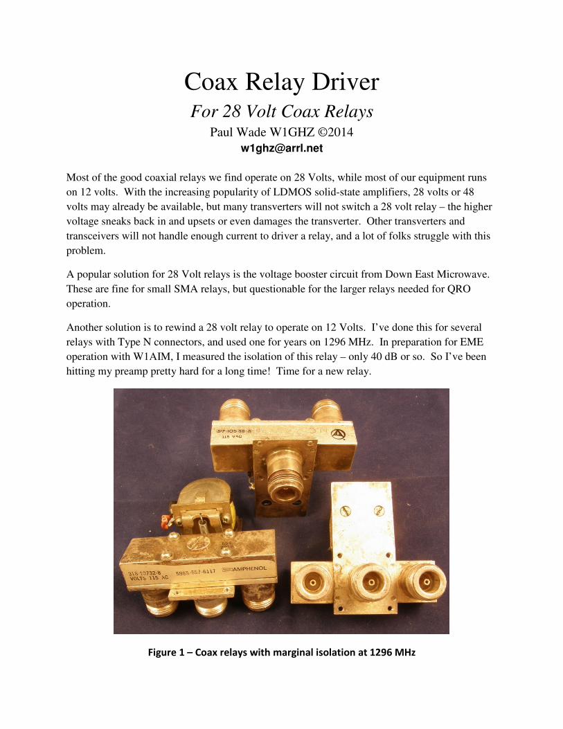
I quickly dug through my coax relay collection and started measuring isolation. All the relays
like Figure 1 were in the 40 dB range, but several like Figure 2 had 60+ dB isolation. They don’t
look easy to rewind for 12 Volts, but my amplifier runs on 28 Volts anyway. They also take a
fair amount of current to switch, 250 to 300 mA at 28 Volts, so the booster is not an option. The
one on the right is a latching relay; that’s a separate problem.
Figure 2 – Coax relays with good isolation at 1296 MHz
Chip has a DB6NT transverter which is specified to only switch 12 Volt relays, and the
schematic confirms that the 28 Volts would feed back into the circuit. My transverter is
homebrew, and I don’t know where the schematic is, but I’m pretty sure the relay driver is a
hefty power FET. I hooked up the relay with 28 Volts to see if the transverter would drive it –
sure enough, the transverter was upset and wouldn’t switch properly.
Time for a proper relay driver that isolates the relay from the driver. I sketched up the circuit in
Figure 3, and built it in an Altoids tin, shown in Figure 4. Construction is quick dead-bug style.
I didn’t bother with a PC board – we needed to get something going. The transverter or
transceiver grounds the PTT line to transmit, and the N-channel power FET, Q2, pulls one end of
the relay to ground – the other end is connected to 28 Volts. Don’t forget the diode across the
relay to catch switching spikes. If the driver is very far from the rig, a zener diode, D4, across
the PTT line might prevent damage from stray voltage surges.
If the relay and driver circuit are powered from the same power supply as the amplifier, then the
relay will never switch unless the amplifier is powered up – a simple fail-safe.
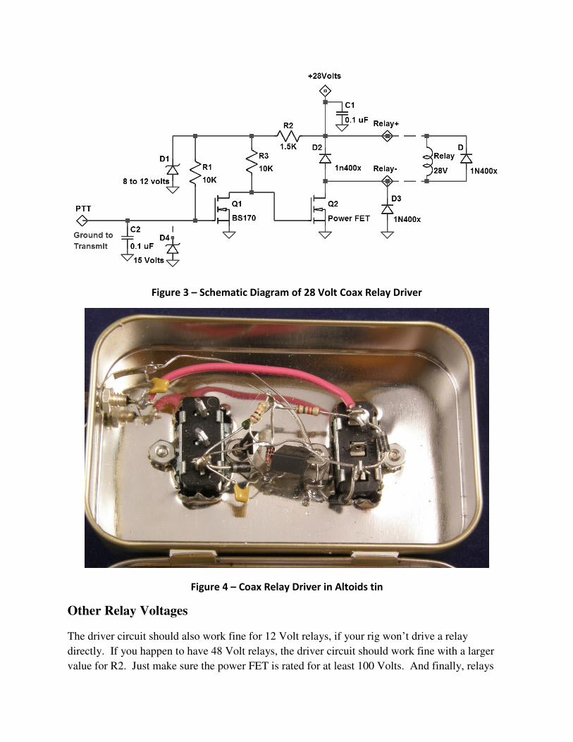
Figure 3 – Schematic Diagram of 28 Volt Coax Relay Driver
Figure 4 – Coax Relay Driver in Altoids tin
Other Relay Voltages
The driver circuit should also work fine for 12 Volt relays, if your rig won’t drive a relay
directly. If you happen to have 48 Volt relays, the driver circuit should work fine with a larger
value for R2. Just make sure the power FET is rated for at least 100 Volts. And finally, relays
for 110 Volts AC will often work fine on 28 Volts DC – give it a try. I’ve used them that way
for years.
Printed Circuit Board Version
I have several other bands in need of better relays, so I’m going to build some more drivers. The
prototype in Figure 4 has worked fine, but the dead-bug wiring is a pain, with lots of potential for
error. Since I was making some PC boards for another project, I did a quick layout and included
a relay driver PCB on an ExpressPCB MiniBoard order. The boards would have arrived in four
days, as promised, except that UPS couldn’t get a truck up the hill.
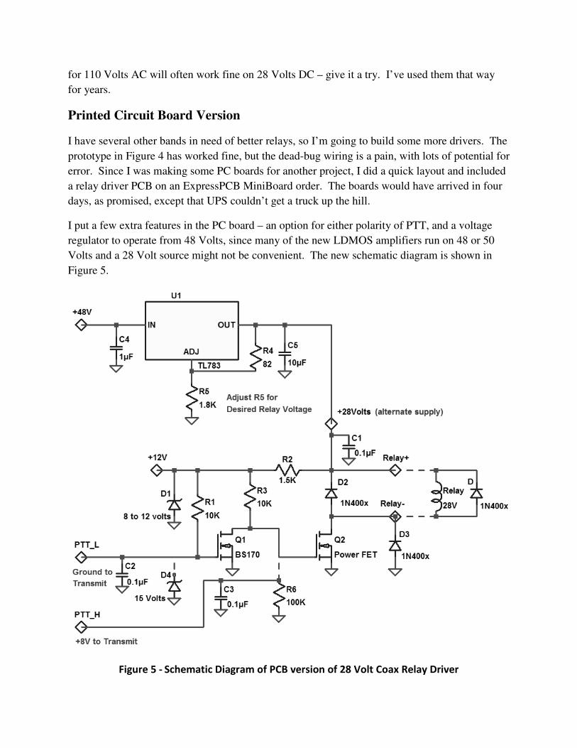
I put a few extra features in the PC board – an option for either polarity of PTT, and a voltage
regulator to operate from 48 Volts, since many of the new LDMOS amplifiers run on 48 or 50
Volts and a 28 Volt source might not be convenient. The new schematic diagram is shown in
Figure 5.
Figure 5 - Schematic Diagram of PCB version of 28 Volt Coax Relay Driver
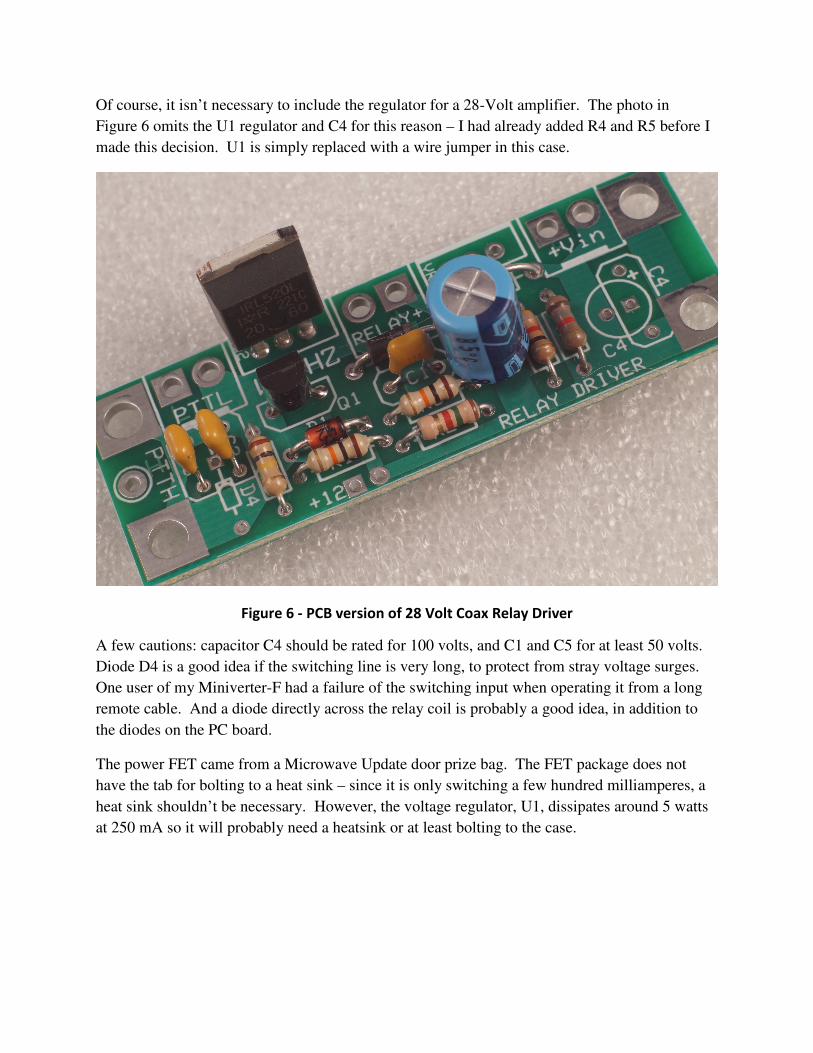
Of course, it isn’t necessary to include the regulator for a 28-Volt amplifier. The photo in
Figure 6 omits the U1 regulator and C4 for this reason – I had already added R4 and R5 before I
made this decision. U1 is simply replaced with a wire jumper in this case.
Figure 6 - PCB version of 28 Volt Coax Relay Driver
A few cautions: capacitor C4 should be rated for 100 volts, and C1 and C5 for at least 50 volts.
Diode D4 is a good idea if the switching line is very long, to protect from stray voltage surges.
One user of my Miniverter-F had a failure of the switching input when operating it from a long
remote cable. And a diode directly across the relay coil is probably a good idea, in addition to
the diodes on the PC board.
The power FET came from a Microwave Update door prize bag. The FET package does not
have the tab for bolting to a heat sink – since it is only switching a few hundred milliamperes, a
heat sink shouldn’t be necessary. However, the voltage regulator, U1, dissipates around 5 watts
at 250 mA so it will probably need a heatsink or at least bolting to the case.