Embed Size (px)
Citation preview

W1GHZ
Microwave
Antenna Book
Online(ex-N1BWT)
W1GHZ
Microwave
Antenna Book
Online(ex-N1BWT)
W1GHZ
Microw
ave
Anten
na Bo
okOnline(ex-N1BWT)
W1GHZ
Microw
ave
Antenn
a Boo
kOnline(ex-N1BWT)
W1GHZ
Microwave
Antenna BookOnline(ex-N1BWT)
W1GHZ
Microwave
Antenna BookOnline(ex-N1BWT)
W1GHZMicrowave
Antenna BookOnline(ex-N1BWT)
W1GHZMicrowave
Antenna BookOnline(ex-N1BWT)
Chapter 6Feeds for Parabolic Dish Antennas
Paul Wade W1GHZ ©1998,1999
Section 6.5 Dual-Mode Feedhorns
6.5.3 Diagonal Horn
The diagonal horn antenna was probably the first successful multi-mode feed horn. A square hornexcited with only the dominant TE
01 waveguide mode has a radiation pattern which is not symmetri-
cal, as we saw in Figure 6.4-10. The asymmetry is caused by E-plane edge currents in the walls ofhorn, the same problem found in conical horns. A. W. Love11 found that exciting an additional mode,the TE
10 mode, orthogonal to the original TE
01 mode, results in radiation which is polarized along the
diagonals of the horn. The resulting symmetry produces a radiation pattern with symmetrical E- andH-planes, suitable for linear or circular polarization. The field at the diagonal horn aperture is similarto the field in a circular horn feed, illustrated in Figure 6.5-20.
The diagonal horn may be designed for a wide rangeof f/D by varying the square dimension of the hornaperture. Love gives approximate beamwidths of58.5 λλλλλ/d for 3 dB beamwidth and 101 λλλλλ/d for 10 dBbeamwidth, where d is the dimension of one side ofthe square aperture. Patterns are best with small flareangles, less than 30°. The diagonal horn does havesidelobes in the 45° pattern cuts (planes at angleshalfway between the E- and H-planes), and thesesidelobes have larger amplitudes as the flare angleincreases.
Love generates the additional mode to produce thediagonal pattern in a circular transition from rectangu-lar waveguide to the square horn. However, N7ART12
excites diagonal horns for 1296 MHz with a diagonal

dipole inside the square waveguide, as shown in Figure6.5-21. W2IMU shows the same technique in the ARRLUHF/Microwave Experimenters Manual13. Circularpolarization may be produced by two crossed dipoles with90° phase shift.
The N7ART article describes a series of horns for f/D fromabout 0.3 to 0.4. Most of these horns are simple open-ended square waveguides with no flare. The smallest, witheach square side 129.5 mm long, or 0.603λ at 1296 MHz— any smaller would probably be beyond waveguidecutoff. The radiation pattern calculated by NEC2 inFigure 6.5-22 shows good efficiency for f/D around 0.3, with the phase center at the center of theaperture. The calculated pattern is quite symmetrical, including the 45 degree planes as well as theE- and H-planes. Efficiency is reduced by a poor front-to-back ratio, just as we saw for open-endedrectangular and circular waveguide feeds.
The pattern calculated by NEC2 in Figure 6.5-23, for a slightly larger version, 139.7 mm square,shows slightly better efficiency for f/D around 0.32. A larger size, 146.1 mm square shown in Figure6.5-24, has best efficiency around f/D=0.35, while the largest plain diagonal waveguide version,157.5 mm square, has best efficiency for f/D around 0.37, as shown in Figure 6.5-25. All theseunflared diagonal horns have good pattern symmetry with the phase center at the center of theaperture. As the size of the unflared diagonal horn increases, the calculated NEC2 patterns showimproving front-to-back ratio resulting in improving efficiency.
N7ART also described a flared diagonal horn for 1296 MHz, flaring out from the square waveguideto a 7 inch (177 mm) square aperture. The flare is gradual, as recommended by Love, with a 10.2°full flare angle. The radiation pattern calculated using P.O. is shown in Figure 6.5-26, with bestefficiency for f/D around 0.4, and a phase center just inside the center of the aperture. Calculated45 degree patterns are almost identical to the E- and H-planes, so symmetry is excellent. The rearnull in the pattern is an artifact of the Physical Optics calculations.
These calculated patterns are slightly broader at the –10 dB points than measured by N7ART, and thecalculated f/D for best efficiencies are very close to the f/D he recommends for lowest noise (bestG/T), but lower than the f/D he recommends for maximum gain. I have more faith in measured datathan computer simulations, so go with N7ART’s suggestions.
Unflared diagonal horns appear to offer the best performance in a small physical size; for a small dish,this would minimize feed blockage for better overall efficiency. The symmetrical pattern allows goodperformance with circular polarization. Thus, for a small dish with circular polarization, like a12-foot TVRO dish for 1296 MHz, the diagonal horn is probably the best feed available.

N7ART 1296 MHz diagonal horn 129.5 mm square, by NEC2
Figure 6.5-22
Dish diameter = 10 λ Feed diameter = 1 λ
E-plane
H-plane
45 degree planes 0 dB -10 -20 -30
Fee
d R
adia
tio
n P
atte
rn
W1GHZ 1998
0 10 20 30 40 50 60 70 80 90-90
-67.5
-45
-22.5
0
22.5
45
67.5
90
Rotation Angle aroundF
eed
Ph
ase
An
gle
E-plane
H-plane
specifiedPhase Center = 0 λ beyond aperture
0.3 0.4 0.5 0.6 0.7 0.8 0.90.25
10
20
30
40
50
60
70
80
90
1 dB
2 dB
3 dB
4 dB
5 dB
6 dB
7 dB8 dB
MAX Possible Efficiency with Phase error
REAL WORLD at least 15% lower
MAX Efficiency without phase error
Illumination Spillover
AFTER LOSSES:
Feed Blockage
Parabolic Dish f/D
Par
abo
lic D
ish
Eff
icie
ncy
%

N7ART 1296 MHz diagonal horn, 139.7 mm square, by NEC2
Figure 6.5-23
Dish diameter = 10 λ Feed diameter = 1 λ
E-plane
H-plane
45 degree planes 0 dB -10 -20 -30
Fee
d R
adia
tio
n P
atte
rn
W1GHZ 1998
0 10 20 30 40 50 60 70 80 90-90
-67.5
-45
-22.5
0
22.5
45
67.5
90
Rotation Angle aroundF
eed
Ph
ase
An
gle
E-plane
H-plane
specifiedPhase Center = 0 λ beyond aperture
0.3 0.4 0.5 0.6 0.7 0.8 0.90.25
10
20
30
40
50
60
70
80
90
1 dB
2 dB
3 dB
4 dB
5 dB
6 dB
7 dB8 dB
MAX Possible Efficiency with Phase error
REAL WORLD at least 15% lower
MAX Efficiency without phase error
Illumination Spillover
AFTER LOSSES:
Feed Blockage
Parabolic Dish f/D
Par
abo
lic D
ish
Eff
icie
ncy
%

N7ART 1296 MHz diagonal horn 146.1 mm square, by NEC2
Figure 6.5-24
Dish diameter = 10 λ Feed diameter = 1 λ
E-plane
H-plane
45 degree planes 0 dB -10 -20 -30
Fee
d R
adia
tio
n P
atte
rn
W1GHZ 1998
0 10 20 30 40 50 60 70 80 90-90
-67.5
-45
-22.5
0
22.5
45
67.5
90
Rotation Angle aroundF
eed
Ph
ase
An
gle
E-plane
H-plane
specifiedPhase Center = 0 λ beyond aperture
0.3 0.4 0.5 0.6 0.7 0.8 0.90.25
10
20
30
40
50
60
70
80
90
1 dB
2 dB
3 dB
4 dB
5 dB
6 dB
7 dB8 dB
MAX Possible Efficiency with Phase error
REAL WORLD at least 15% lower
MAX Efficiency without phase error
Illumination Spillover
AFTER LOSSES:
Feed Blockage
Parabolic Dish f/D
Par
abo
lic D
ish
Eff
icie
ncy
%

N7ART 1296 MHz diagonal horn 157.5 mm square, by NEC2
Figure 6.5-25
Dish diameter = 10 λ Feed diameter = 1 λ
E-plane
H-plane
45 degree planes 0 dB -10 -20 -30
Fee
d R
adia
tio
n P
atte
rn
W1GHZ 1998
0 10 20 30 40 50 60 70 80 90-90
-67.5
-45
-22.5
0
22.5
45
67.5
90
Rotation Angle aroundF
eed
Ph
ase
An
gle
E-plane
H-plane
specifiedPhase Center = 0 λ beyond aperture
0.3 0.4 0.5 0.6 0.7 0.8 0.90.25
10
20
30
40
50
60
70
80
90
1 dB
2 dB
3 dB
4 dB
5 dB
6 dB
7 dB8 dB
MAX Possible Efficiency with Phase error
REAL WORLD at least 15% lower
MAX Efficiency without phase error
Illumination Spillover
AFTER LOSSES:
Feed Blockage
Parabolic Dish f/D
Par
abo
lic D
ish
Eff
icie
ncy
%

N7ART 1296 MHz diag horn, 7" square, 10.2 deg flare, by P.O.
Figure 6.5-26
Dish diameter = 10 λ Feed diameter = 1 λ
E-plane
H-plane
0 dB -10 -20 -30
Fee
d R
adia
tio
n P
atte
rn
W1GHZ 1998
0 10 20 30 40 50 60 70 80 90-90
-67.5
-45
-22.5
0
22.5
45
67.5
90
Rotation Angle aroundF
eed
Ph
ase
An
gle
E-plane
H-plane
specifiedPhase Center = 0 λ beyond aperture
0.3 0.4 0.5 0.6 0.7 0.8 0.90.25
10
20
30
40
50
60
70
80
90
1 dB
2 dB
3 dB
4 dB
5 dB
6 dB
7 dB8 dB
MAX Possible Efficiency with Phase error
REAL WORLD at least 15% lower
MAX Efficiency without phase error
Illumination Spillover
AFTER LOSSES:
Feed Blockage
Parabolic Dish f/D
Par
abo
lic D
ish
Eff
icie
ncy
%

VE1ALQ takes advantage of the small sizeof the diagonal horn in a dual-band feed for1296 and 432 MHz. In Figure 6.5-27, thediagonal horn for 1296 is in the center of a432 MHz EIA dual-dipole feed. The phasecenter of the EIA feed, in Figure 6.2-6, isabout 0.15λ behind the dipoles, while thediagonal horn phase center is at the center ofthe aperture. The photo shows thatVE1ALQ has arrived at this combinationempirically.
Diagonal horns can also be used for larger f/D by increasing the horn aperture size. For example, aDSS offset dish requires an illumination angle of about 75°, equivalent to an f/D of about 0.7. I usedLove’s estimate of 101 λλλλλ/d for 10 dB beamwidth to estimate a desired aperture dimension of 1.35λsquare. The calculated pattern with a 30° flare angle was a bit wide, so I increased the aperturedimension to 1.4λ square. Then I played with the flare angle. W2IMU13 suggests a maximum of7° half-angle, which would result in a rather long horn. Since Love11 states that 45° sidelobesincrease with flare angle, but doesn’t say how much, I calculated patterns for 30° and 60° flare tocompare with the 14° suggested by W2IMU.
The radiation pattern and efficiency calculatedusing P.O. for a 1.4λ square diagonal horn with14° flare (full angle) are shown in Figure 6.5-28,with a clean pattern, small 45° sidelobes, andexcellent efficiency for the offset dish equivalentf/D of about 0.7. The estimated phase center isabout 0.07λ inside the aperture.
Increasing the flare angle to 30° resulted inslightly larger 45° sidelobes, as shown in Figure6.5-29. Efficiency is very slightly lower than thelonger horn, with the phase center 0.13λ insidethe aperture. However, a 60° flare angle pro-duces larger 45° sidelobes that lower the calcu-lated efficiency noticeably, as shown in Figure6.5-30. Phase center for this horn is 0.285λinside the aperture.
Since the 30° flare angle provides excellentcalculated efficiency, I decided to build this one,as well as the more compact 60° flare to see if thedifference in performance would be measurable.I chose to excite these feed horns directly from
Template for10.368 GHz Offset diagonal horn1.4 wavelengths square60 degree flare
E-planeW1GHZ 1994,1998
Figure 6.5-31

Offset diagonal horn, 1.4λ square, 14 degree full flare, by P.O.
Figure 6.5-28
Dish diameter = 15.8 λ Feed diameter = 0.5 λ
E&H planes
45 planes
0 dB -10 -20 -30
Fee
d R
adia
tio
n P
atte
rn
W1GHZ 1998
0 10 20 30 40 50 60 70 80 90-90
-67.5
-45
-22.5
0
22.5
45
67.5
90
Rotation Angle aroundF
eed
Ph
ase
An
gle
E-plane
H-plane
specifiedPhase Center = 0.07 λ inside aperture
0.3 0.4 0.5 0.6 0.7 0.8 0.90.25
10
20
30
40
50
60
70
80
90
1 dB
2 dB
3 dB
4 dB
5 dB
6 dB
7 dB8 dB
MAX Possible Efficiency with Phase error
REAL WORLD at least 15% lower
MAX Efficiency without phase error
Illumination Spillover
AFTER LOSSES:
Feed Blockage
Parabolic Dish f/D
Par
abo
lic D
ish
Eff
icie
ncy
%

Offset diagonal horn 1.4λ square, 30 degree full flare, by P.O.
Figure 6.5-29
Dish diameter = 15.8 λ Feed diameter = 0.5 λ
E&H planes
45˚ planes
0 dB -10 -20 -30
Fee
d R
adia
tio
n P
atte
rn
W1GHZ 1998
0 10 20 30 40 50 60 70 80 90-90
-67.5
-45
-22.5
0
22.5
45
67.5
90
Rotation Angle aroundF
eed
Ph
ase
An
gle
E-plane
H-plane
specifiedPhase Center = 0.13 λ inside aperture
0.3 0.4 0.5 0.6 0.7 0.8 0.90.25
10
20
30
40
50
60
70
80
90
1 dB
2 dB
3 dB
4 dB
5 dB
6 dB
7 dB8 dB
MAX Possible Efficiency with Phase error
REAL WORLD at least 15% lower
MAX Efficiency without phase error
Illumination Spillover
AFTER LOSSES:
Feed Blockage
Parabolic Dish f/D
Par
abo
lic D
ish
Eff
icie
ncy
%

Offset diagonal horn, 1.4λ square, 60 degree full flare, by P.O.
Figure 6.5-30
Dish diameter = 15.8 λ Feed diameter = 0.5 λ
E&H planes
45 planes
0 dB -10 -20 -30
Fee
d R
adia
tio
n P
atte
rn
W1GHZ 1998
0 10 20 30 40 50 60 70 80 90-90
-67.5
-45
-22.5
0
22.5
45
67.5
90
Rotation Angle aroundF
eed
Ph
ase
An
gle
E-plane
H-plane
specifiedPhase Center = 0.285 λ inside aperture
0.3 0.4 0.5 0.6 0.7 0.8 0.90.25
10
20
30
40
50
60
70
80
90
1 dB
2 dB
3 dB
4 dB
5 dB
6 dB
7 dB8 dB
MAX Possible Efficiency with Phase error
REAL WORLD at least 15% lower
MAX Efficiency without phase error
Illumination Spillover
AFTER LOSSES:
Feed Blockage
Parabolic Dish f/D
Par
abo
lic D
ish
Eff
icie
ncy
%

circular waveguide — at 10 GHz, the waveguide is ¾” copper water pipe. The transition to squarecross-section was formed by hammering one end of the pipe on a square mandrel. Then the hornsections were cut from sheet copper using the HDL_ANT templates like Figure 6.5-31, and solderedto the square end of the waveguide transitions. The completed horns are shown in Figure 6.5-32.
I made sun noise measurements on offset dishes fed with the diagonal horns in Figure 6.5-32 withdisappointing results. The 30° flare horn yielded a measured efficiency of 45 to 47%, while the60° flare version measured only 39% efficiency. I then rotated the polarization so that the hornswould operate as square horns in the TE
01 mode, like Figure 6.4-22. As square horns, the efficiency
is several percent higher in both cases, while the calculated efficiencies were lower. My suspicion isthat the short hammered transition from round to square cross-section does not properly launch theadditional mode for diagonal horn operation; I will have to try ways to fabricate a better taper.
As an example of an even larger diagonal horn, I investigated one to feed a large Gregorian-styleshaped reflector dish for Lyle, VK2ALU. This is intended as a 10 GHz replacement for the 12 GHzcorrugated horn of Figure 6.4-22. The desired illumination angle for the subreflector is about 28°,but with a bit more than 10 dB edge taper. One possibility, the result of several trial calculations, isshown in Figure 6.5-33, with an aperture of 2.8λ and a flare angle of 30°. The pattern exhibits somesignificant sidelobes in the 45° planes; reducing the flare angle might improve these sidelobes, butwould make the horn very long. The phase center for this large horn is 1.3 wavelengths inside theaperture. Because of the sidelobes, Lyle chose to investigate another alternative, described later inthis section.
The diagonal horn has two attractive features as a feedhorn: its small size reduces blockage loss, andits square shape is relatively easy to fabricate. As we have seen from the examples, it is possible todimension a diagonal horn for a full range of f/D. Disadvantages are the high sidelobe levels in the45° planes, and the difficulty of interfacing to standard rectangular waveguide feedlines.
The sidelobe levels in the 45° planes are less of a disadvantage for ham use than in commercial appli-cations. The 45° sidelobes tend to produce cross-polarized radiation, particularly with offset reflec-tors. Since most satellite broadcasting systems use polarization diversity to double the number ofchannels, cross-polarization is highly undesirable.

Diagonal horn, 2.8λ square, 30 degree flare, by P.O.
Figure 6.5-33
Dish diameter = 28 λ Feed diameter = 2.8 λ
E&H planes
45 planes
0 dB -10 -20 -30
Fee
d R
adia
tio
n P
atte
rn
W1GHZ 1999
0 10 20 30 40 50 60 70 80 90-90
-67.5
-45
-22.5
0
22.5
45
67.5
90
Rotation Angle aroundF
eed
Ph
ase
An
gle
E-plane
H-plane
specifiedPhase Center = 1.3 λ inside aperture
0.5 0.75 1 1.2 1.5 1.80.25 2.0
10
20
30
40
50
60
70
80
90
1 dB
2 dB
3 dB
4 dB
5 dB
6 dB
7 dB8 dB
MAX Possible Efficiency with Phase error
REAL WORLD at least 15% lower
MAX Efficiency without phase error
Illumination Spillover
AFTER LOSSES:
Feed Blockage
Parabolic Dish f/D
Par
abo
lic D
ish
Eff
icie
ncy
%

6.5.4 Potter dual-mode conical horn
After the diagonal horn, the next development in multi-mode feedhorns was the dual-mode conicalhorn by Potter14. This horn has better sidelobe levels than the diagonal horn, particularly in the 45°planes. It takes advantage of the symmetry of a conical horn while reducing the E-plane sidelobes wesaw in section 6.4-1 by exciting the TM
11 mode in addition to the dominant TE
11 mode, with relative
amplitudes so that the sidelobes produced by the two modes are out of phase and cancel, just as wesaw in Figures 6.5-5 and 6.5-6. The Potter horn was apparently the inspiration for W2IMU to de-velop his dual-mode horn1 discussed in section 6.5-1.
Design of the Potter dual-mode horn is quite complex; Figure 6.5-34 is a sketch. Starting at the left,section A is the input circular waveguide, with a diameter such that only the dominant TE
11 mode
may propagate. The flared section, B, expands this diameter to the desired input diameter for thestep transition, C, that generates the TM
11 mode. The relative amplitude of the two modes is deter-
mined by the two diameters at the step transition, with only the larger output diameter of D capableof propagating multiple modes. A constant diameter phasing section, D, is used to adjust the phase ofthe two modes, since they travel at different phase velocities in the waveguide. Finally, the twomodes arrive at the throat of the conical horn, E, with the desired relative amplitude and phase. Therelative phase of the two modes is also shifted by the conical horn, so the length of section D mustcompensate for this phase shift so that the two modes arrive in-phase at the center of the aperture.The fields of the two modes are then out-of-phase at the aperture edges in the E-plane, like Figures6.5-5, resulting in elimination of the edge currents which create sidelobes in simple conical horns.
Potter dual-mode conical horn
Figure 6.5-34
A B C D E

The calculations are too involved to include here, and a careful reading of Potter’s paper14 is recom-mended. The equation for phase shift in the flared conical horn has eight terms, with Bessel functionsneeded for each term; I have not attempted the calculation. The paper does include some graphicalsolutions which should be easier to use. Construction also appears quite involved, and he recom-mends that concentricity and circularity in the order of a few thousandths of a wavelength are neces-sary to prevent spurious waveguide modes. Due to this complexity, I had always thought that thishorn would not be useful for hams. However, I recently received email from F4BAY describing his10 GHz feedhorn. He scaled a 12 GHz DSS horn from an “ASTRA” offset dish to 10.37 GHz andmeasured the radiation pattern. As I prepared an NEC2 computer model, I realized that this was aPotter dual-mode conical horn. The calculated radiation patterns, in Figure 6.5-35, show excellentefficiency for an f/D around 0.6, with a phase center very close to the center of the aperture. Themeasured data from F4BAY, shown in dashed green lines, is close to the calculated data.
6.5.5 VK2ALU dual-mode feedhorn
VK2ALU has discovered a simpler approach to construction; he was considering the Potter feed asan alternative to the diagonal horn in Figure 6.5-33 to reduce the 45° sidelobe levels. Lyle realizedthat the W2IMU dual-mode horn uses a simpler method, a flared section, of generating the twomodes, and the same method could be applied to a conical dual-mode horn as well. For simplicity, hestarted with the G3PHO version for 10 GHz, Figure 6.5-7, and added a conical horn to realize alarger aperture. Lyle studied Potter’s paper and arrived at a horn length and flare angle that producedthe same relative phase at the aperture. The horn is quite long, as can be seen in Figure 6.5-36.

F4BAY Potter type dual-mode horn for 10.368 GHz, by NEC2
Figure 6.5-35
Dish diameter = 20 λ Feed diameter = 2 λ
E-plane
H-plane
0 dB -10 -20 -30
Fee
d R
adia
tio
n P
atte
rn
W1GHZ 1998
0 10 20 30 40 50 60 70 80 90-90
-67.5
-45
-22.5
0
22.5
45
67.5
90
Rotation Angle aroundF
eed
Ph
ase
An
gle
E-plane
H-plane
specifiedPhase Center = 0.03 λ beyond aperture
0.3 0.4 0.5 0.6 0.7 0.8 0.90.25
10
20
30
40
50
60
70
80
90
1 dB
2 dB
3 dB
4 dB
5 dB
6 dB
7 dB8 dB
MAX Possible Efficiency with Phase error
REAL WORLD at least 15% lower
MAX Efficiency without phase error
Illumination Spillover
AFTER LOSSES:
Feed Blockage
Parabolic Dish f/D
Par
abo
lic D
ish
Eff
icie
ncy
%

The length of Lyle’s feedhorn was originally too large to calculate using NEC2 — my PC does nothave enough memory — so I calculated approximate radiation patterns using P.O. The results areshown in Figure 6.5-37, with excellent performance for an f/D around 1.5. Phase center is about0.4λ inside the aperture. Lyle made careful measurements of the feedhorn radiation pattern; these arealso shown in Figure 6.5-37 in dashed green lines. The only difference between the calculated andmeasured patterns is the first null in the calculated E-plane pattern, which is almost non-existent in themeasured pattern. There are at least three possible reasons for this difference:
1. Compromises I made in the calculations.2. Stray reflections on the antenna range.3. Small discrepancies in dimensions with fortuitous results.
Later, I was able to use a faster PC with more memory, 128 Megabytes, to run an NEC2 model forthe VK2ALU feedhorn. Even with the larger memory, I was unable to make a fine enough mode, sothe calculated radiation patterns have excessive side and back lobes. The NEC2 patterns are shownin yellow in Figure 6.5-37; the main lobe matches the measured data and P.O. calculations, and showsthe same first null in the E-plane pattern.
The VK2ALU dual-mode feed compares favorably with the original 12 GHz corrugated horn ofFigure 6.4-22. Lyle is in the process of making sun noise measurements and reports promising initialresults.
After I understood Lyle’s approach to the dual-mode conical feed, I examined another feedhorn I hadlying around. The horn was part of an assembly with two LNBs, usually beige in color; we bought anumber of them to convert the LNBs to 10 GHz preamps15. The input waveguide to the horn israther small for 10.368 GHz, just about at cutoff, and there isn’t enough metal to bore it out, so I hadnever tried one. However, the design seemed similar to Lyle’s approach, so I made an NEC2 modelfor 12 GHz and calculated radiation patterns. Figure 6.5-38 shows the results, with excellentcalculated efficiency for an f/D around 0.7, ideal for an offset dish. The calculated phase center is0.14λ inside the aperture.
Of course, the next question is, “will it work at 10 GHz?” A simple matter of changing the frequencyfor the NEC2 calculations will give us the answer: not very well. The calculated radiation patterns at10.368 GHz in Figure 6.5-39 have a number of large sidelobes, particularly in the E-plane, andsignificant phase error, so the calculated efficiency is poor. We can conclude that a dual-mode horn isnot broadband; the phase-matching mechanism for the two modes is frequency sensitive.
A photo of this last horn is Figure 6.5-40. The conical horn is much shorter than VK2ALU’s horn,since Lyle chose to start with the known phase relationship of the two modes produced by theG3PHO dual-mode horn. The alternative approach, used in the feedhorn in Figure 6.5-40, is to startwith a conical horn section of reasonable length and flare angle, then adjust the length of the phasingsection, D in Figure 6.5-34, to arrive at the desired phase relationship at the aperture. A thirdapproach, the favorite for hams, is to scale a working design to a new frequency; it worked well forF4BAY, and could be applied to this horn as well.

VK2ALU dual-mode feedhorn for 10.368 GHz
Red & Blue = P.O., Green = Measured, Yellow = NEC2
Figure 6.5-37
Dish diameter = 128 λ Feed diameter = 10 λ
E-plane
H-plane
0 dB -10 -20 -30
Fee
d R
adia
tio
n P
atte
rn
W1GHZ 1999
0 10 20 30 40 50 60 70 80 90-90
-67.5
-45
-22.5
0
22.5
45
67.5
90
Rotation Angle aroundF
eed
Ph
ase
An
gle
E-plane
H-plane
specifiedPhase Center = 0.4 λ inside aperture
0.5 0.75 1 1.2 1.5 1.80.25 2.0
10
20
30
40
50
60
70
80
90
1 dB
2 dB
3 dB
4 dB
5 dB
6 dB
7 dB8 dB
MAX Possible Efficiency with Phase error
REAL WORLD at least 15% lower
MAX Efficiency without phase error
Illumination Spillover
AFTER LOSSES:
Feed Blockage
Parabolic Dish f/D
Par
abo
lic D
ish
Eff
icie
ncy
%

TVRO 12 GHz feedhorn from beige LNB assembly, by NEC2
Figure 6.5-38
Dish diameter = 20 λ Feed diameter = 2 λ
E-plane
H-plane
0 dB -10 -20 -30
Fee
d R
adia
tio
n P
atte
rn
W1GHZ 1998
0 10 20 30 40 50 60 70 80 90-90
-67.5
-45
-22.5
0
22.5
45
67.5
90
Rotation Angle aroundF
eed
Ph
ase
An
gle
E-plane
H-plane
specifiedPhase Center = 0.14 λ inside aperture
0.3 0.4 0.5 0.6 0.7 0.8 0.90.25
10
20
30
40
50
60
70
80
90
1 dB
2 dB
3 dB
4 dB
5 dB
6 dB
7 dB8 dB
MAX Possible Efficiency with Phase error
REAL WORLD at least 15% lower
MAX Efficiency without phase error
Illumination Spillover
AFTER LOSSES:
Feed Blockage
Parabolic Dish f/D
Par
abo
lic D
ish
Eff
icie
ncy
%

TVRO feedhorn from beige LNB at 10.368 GHz, by NEC2
Figure 6.5-39
Dish diameter = 20 λ Feed diameter = 0.5 λ
E-plane
H-plane
0 dB -10 -20 -30
Fee
d R
adia
tio
n P
atte
rn
W1GHZ 1998
0 10 20 30 40 50 60 70 80 90-90
-67.5
-45
-22.5
0
22.5
45
67.5
90
Rotation Angle aroundF
eed
Ph
ase
An
gle
E-plane
H-plane
specifiedPhase Center = 0.07 λ inside aperture
0.3 0.4 0.5 0.6 0.7 0.8 0.90.25
10
20
30
40
50
60
70
80
90
1 dB
2 dB
3 dB
4 dB
5 dB
6 dB
7 dB8 dB
MAX Possible Efficiency with Phase error
REAL WORLD at least 15% lower
MAX Efficiency without phase error
Illumination Spillover
AFTER LOSSES:
Feed Blockage
Parabolic Dish f/D
Par
abo
lic D
ish
Eff
icie
ncy
%
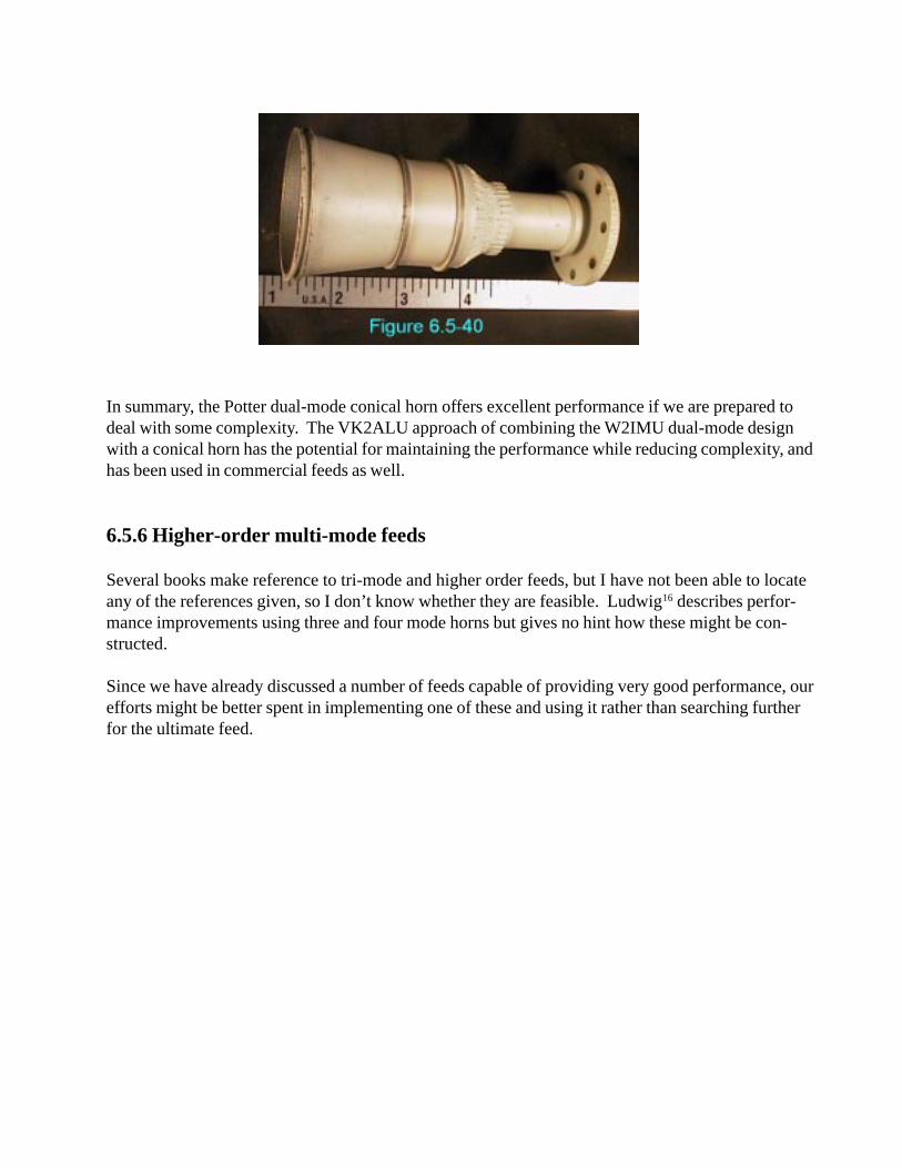
In summary, the Potter dual-mode conical horn offers excellent performance if we are prepared todeal with some complexity. The VK2ALU approach of combining the W2IMU dual-mode designwith a conical horn has the potential for maintaining the performance while reducing complexity, andhas been used in commercial feeds as well.
6.5.6 Higher-order multi-mode feeds
Several books make reference to tri-mode and higher order feeds, but I have not been able to locateany of the references given, so I don’t know whether they are feasible. Ludwig16 describes perfor-mance improvements using three and four mode horns but gives no hint how these might be con-structed.
Since we have already discussed a number of feeds capable of providing very good performance, ourefforts might be better spent in implementing one of these and using it rather than searching furtherfor the ultimate feed.

6.5 References (continued)
11. A.W. Love, “The Diagonal Horn Antenna,” Microwave Journal, March 1962, pp. 117-122.(reprinted in A.W. Love, Electromagnetic Horn Antennas, IEEE, 1976, pp. 189-194.)
12.R. Miller, N7ART, “A 23cm Diagonal Waveguide Feed,” DUBUS, 2/1997, pp. 5-14.
13.D. Turrin, W2IMU, “Parabolic Reflector Antennas and Feeds,” The ARRL UHF/MicrowaveExperimenter’s Manual, ARRL, 1990, p. 9-29.
14.P.D. Potter, “A New Horn Antenna with Suppressed Sidelobes and Equal Beamwidths,”Microwave Journal, June 1963, pp. 71-78. (reprinted in A.W. Love, Electromagnetic HornAntennas, IEEE, 1976, pp. 195-202.)
15.P. Wade, N1BWT, and D. Twombly, WB1FKF, “Modification of TVRO LNBs for 10 GHz,”QEX, April 1995, pp. 3-5.
16.A.C. Ludwig, “Radiation Pattern Synthesis for Circular Aperture Horn Antennas,” IEEETransactions on Antennas and Propagation, July 1966, pp. 434-440. (reprinted in A.W. Love,Electromagnetic Horn Antennas, IEEE, 1976, pp. 207-213.)