Embed Size (px)
Citation preview

Codes for Automatic Ultrasonic Testing (AUT) of Pipeline Girth Welds
Mirmajid Ghaemi Msc. Mechanical Engineer ASNT Level III ET/MT/PT/RT/UT/VT IRAN NDT – Tehran – Iran
Abstract : Pipelines are typically constructed by joining sections of pipes together using either manual or automatic welding . Such pipelines are used to transport water, oil, gas or chemicals for onshore or offshore applications . Pipelines for petroleum industries that is the objective of this paper are used mainly to operate at high percentage of yield strength and carrying dangerous and high flammable liquid or gas. Therefore , such pipelines specially the girth welds that are welded at site must be constructed and inspected to high standard. For many years traditionally Radiography (RT) has been used as Non-Destructive Testing ( NDT)method for inspection of these welds . Radiography provides a real sectional or panoramic picture of the weld and a complete single girth weld can be tested by a single radiation shot . But RT has some major disadvantages like : Safety hazard of radiation , disability to detect planar defects , need for consumables ( film, chemicals ) and Lab for film processing and finally due to the delay to get the test results RT cannot be used as welding process control . Because of all these disadvantages of RT , specially after developing Automatic GMAW welding systems for pipeline welding and achieving smooth and uniform weld geometry , there was always a trend to replace it by Ultrasonic Testing (UT) . The only possibility was to use manual UT but traditional manual ultrasonic testing has also other disadvantages like : real picture cannot be obtained , test results are hardly operator related and testing process is much more time consuming than radiography . Because of all these shortcomings , despite of accepting by most of related codes and standards , manual UT has never been used as a routine method for testing girth welds and its application was restricted for testing only repair welds or tie-in welds . But by invention of AUT and further developments like introducing Phased Array technique, New focusing probes, Time of Flight Diffraction method and using modern computer technology , AUT has been used extensively within the recent years and it has been recognized as the main NDT method and the reliable safe replacement inspection method instead of RT in pipeline construction . By this method not only the system locates the defective areas along the weld length , but by means of discrete zone discrimination it can also establish the vertical position and vertical extent of the defect . This precision defect location and assessment of vertical extent is the principle of ECA ( Engineering Critical Assessment ) . Since some years ago International pipeline standards like API 1104 , CSA Z662 , DNV OS F101, and ISO 13847 have included AUT as an acceptable NDT method for pipeline girth weld inspection . The procedure for this test has been outlined in detail in ASTM E-1961 since 1988 . Also in IIW ( International Institute of Welding ) in the framework of Quality Assurance of Welds , the Sub-commission VC who is dedicated to Ultrasonic weld testing , is currently working on a comprehensive handbook that is mainly focused on New UT methods particularly Phased array and TOFD techniques and their specific applications for pipeline girth weld inspection . Recently, trials to use Automatic welding systems as well as AUT in Iranian pipeline projects have been started and some offshore pipeline girth welds have been inspected by AUT by European contractors . In parallel National Iranian Gas Co. ( NIGC ) has imported 2 Automatic welding systems with 2 modern Phased Array+TOFD AUT systems for first trials . In this paper AUT for testing pipeline girth welds as well as the advanced techniques are described and the latest codes and standards are evaluated . The most common standard for this applications ASTM E-1061 is studied in details. Introduction : Pipes are made in pipe mills either as seamless pipe or welded pipe by rolling plate and welding the seam as longitudinal or spiral weld seam . Depending on the application of pipes , different international or national standards are used in pipe mills for non-destructive testing of the body and weld seam of pipes . According to the applicable standards a proper NDT method is applied during the production . The pipes that need NDT are mainly used in oil and gas pipelines as well as in chemical and petrochemical industries as boiler or condenser tubes . Standards like API 5L , ASTM A53, DIN 2440, BS 1387, SEP 1917 & 1925 or Iranian National Petroleum standard ( IPS ) and Iranian Gas Standard ( IGS ) are used extensively in pipe mills for non-destructive testing of pieces of pipes . Most NDT methods are applied automatically or semi-automatically for testing such pipes . Small diameter pipes below 8 inches with thin wall thickness below 6 mm usually are tested by Eddy Current method . Medium size and large size pipes are usually tested by automatic ultrasonic testing . X-Ray and Magnetic Particle test methods are 1
11th European Conference on Non-Destructive Testing (ECNDT 2014), October 6-10, 2014, Prague, Czech Republic
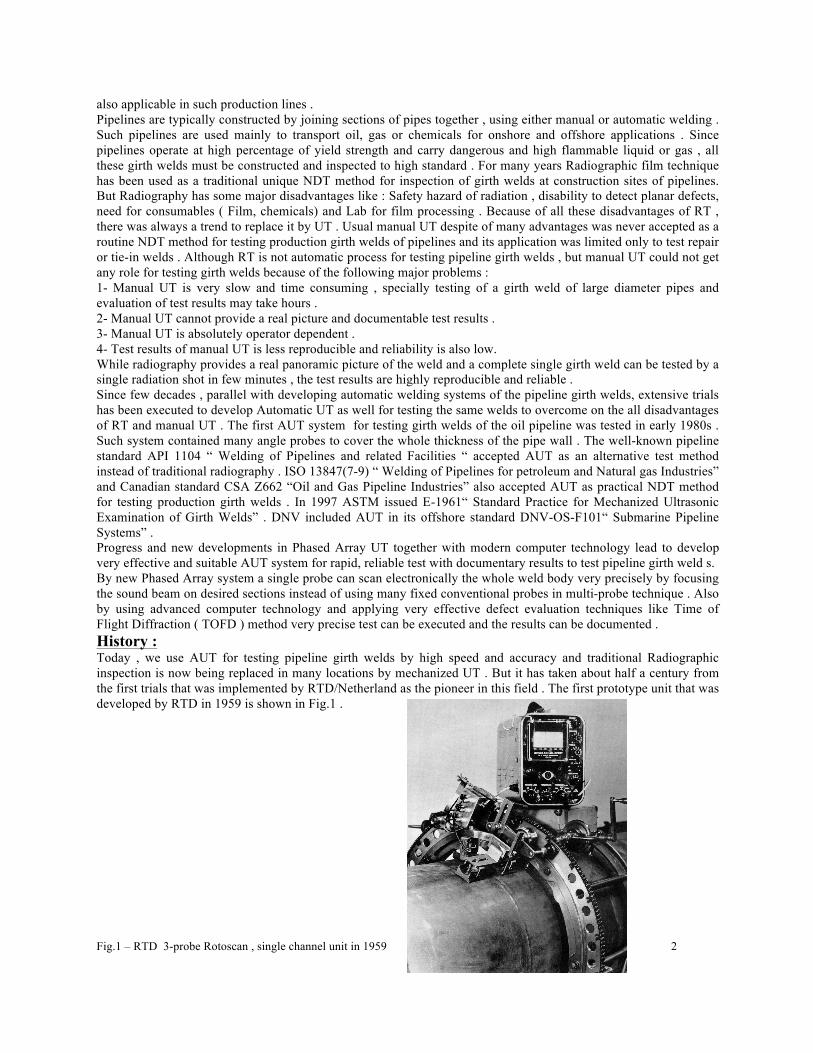
also applicable in such production lines . Pipelines are typically constructed by joining sections of pipes together , using either manual or automatic welding . Such pipelines are used mainly to transport oil, gas or chemicals for onshore and offshore applications . Since pipelines operate at high percentage of yield strength and carry dangerous and high flammable liquid or gas , all these girth welds must be constructed and inspected to high standard . For many years Radiographic film technique has been used as a traditional unique NDT method for inspection of girth welds at construction sites of pipelines. But Radiography has some major disadvantages like : Safety hazard of radiation , disability to detect planar defects, need for consumables ( Film, chemicals) and Lab for film processing . Because of all these disadvantages of RT , there was always a trend to replace it by UT . Usual manual UT despite of many advantages was never accepted as a routine NDT method for testing production girth welds of pipelines and its application was limited only to test repair or tie-in welds . Although RT is not automatic process for testing pipeline girth welds , but manual UT could not get any role for testing girth welds because of the following major problems : 1- Manual UT is very slow and time consuming , specially testing of a girth weld of large diameter pipes and evaluation of test results may take hours . 2- Manual UT cannot provide a real picture and documentable test results . 3- Manual UT is absolutely operator dependent . 4- Test results of manual UT is less reproducible and reliability is also low. While radiography provides a real panoramic picture of the weld and a complete single girth weld can be tested by a single radiation shot in few minutes , the test results are highly reproducible and reliable . Since few decades , parallel with developing automatic welding systems of the pipeline girth welds, extensive trials has been executed to develop Automatic UT as well for testing the same welds to overcome on the all disadvantages of RT and manual UT . The first AUT system for testing girth welds of the oil pipeline was tested in early 1980s . Such system contained many angle probes to cover the whole thickness of the pipe wall . The well-known pipeline standard API 1104 “ Welding of Pipelines and related Facilities “ accepted AUT as an alternative test method instead of traditional radiography . ISO 13847(7-9) “ Welding of Pipelines for petroleum and Natural gas Industries” and Canadian standard CSA Z662 “Oil and Gas Pipeline Industries” also accepted AUT as practical NDT method for testing production girth welds . In 1997 ASTM issued E-1961“ Standard Practice for Mechanized Ultrasonic Examination of Girth Welds” . DNV included AUT in its offshore standard DNV-OS-F101“ Submarine Pipeline Systems” . Progress and new developments in Phased Array UT together with modern computer technology lead to develop very effective and suitable AUT system for rapid, reliable test with documentary results to test pipeline girth weld s. By new Phased Array system a single probe can scan electronically the whole weld body very precisely by focusing the sound beam on desired sections instead of using many fixed conventional probes in multi-probe technique . Also by using advanced computer technology and applying very effective defect evaluation techniques like Time of Flight Diffraction ( TOFD ) method very precise test can be executed and the results can be documented . History : Today , we use AUT for testing pipeline girth welds by high speed and accuracy and traditional Radiographic inspection is now being replaced in many locations by mechanized UT . But it has taken about half a century from the first trials that was implemented by RTD/Netherland as the pioneer in this field . The first prototype unit that was developed by RTD in 1959 is shown in Fig.1 . Fig.1 – RTD 3-probe Rotoscan , single channel unit in 1959 ` 2
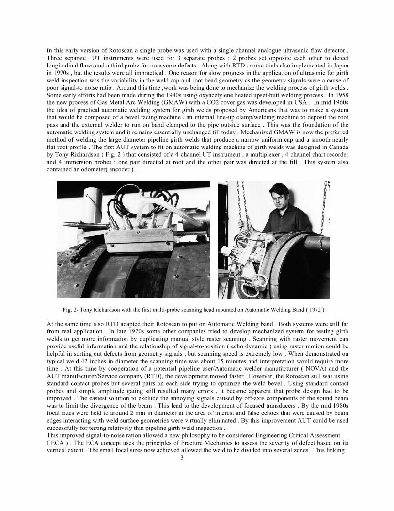
In this early version of Rotoscan a single probe was used with a single channel analogue ultrasonic flaw detector . Three separate UT instruments were used for 3 separate probes : 2 probes set opposite each other to detect longitudinal flaws and a third probe for transverse defects . Along with RTD , some trials also implemented in Japan in 1970s , but the results were all impractical . One reason for slow progress in the application of ultrasonic for girth weld inspection was the variability in the weld cap and root bead geometry as the geometry signals were a cause of poor signal-to noise ratio . Around this time ,work was being done to mechanize the welding process of girth welds . Some early efforts had been made during the 1940s using oxyacetylene heated upset-butt welding process . In 1958 the new process of Gas Metal Arc Welding (GMAW) with a CO2 cover gas was developed in USA . In mid 1960s the idea of practical automatic welding system for girth welds proposed by Americans that was to make a system that would be composed of a bevel facing machine , an internal line-up clamp/welding machine to deposit the root pass and the external welder to run on band clamped to the pipe outside surface . This was the foundation of the automatic welding system and it remains essentially unchanged till today . Mechanized GMAW is now the preferred method of welding the large diameter pipeline girth welds that produce a narrow uniform cap and a smooth nearly flat root profile . The first AUT system to fit on automatic welding machine of girth welds was designed in Canada by Tony Richardson ( Fig. 2 ) that consisted of a 4-channel UT instrument , a multiplexer , 4-channel chart recorder and 4 immersion probes : one pair directed at root and the other pair was directed at the fill . This system also contained an odometer( encoder ) .
Fig. 2- Tony Richardson with the first multi-probe scanning head mounted on Automatic Welding Band ( 1972 ) At the same time also RTD adapted their Rotoscan to put on Automatic Welding band . Both systems were still far from real application . In late 1970s some other companies tried to develop mechanized system for testing girth welds to get more information by duplicating manual style raster scanning . Scanning with raster movement can provide useful information and the relationship of signal-to-position ( echo dynamic ) using raster motion could be helpful in sorting out defects from geometry signals , but scanning speed is extremely low . When demonstrated on typical weld 42 inches in diameter the scanning time was about 15 minutes and interpretation would require more time . At this time by cooperation of a potential pipeline user/Automatic welder manufacturer ( NOVA) and the AUT manufacturer/Service company (RTD), the development moved faster . However, the Rotoscan still was using standard contact probes but several pairs on each side trying to optimize the weld bevel . Using standard contact probes and simple amplitude gating still resulted many errors . It became apparent that probe design had to be improved . The easiest solution to exclude the annoying signals caused by off-axis components of the sound beam was to limit the divergence of the beam . This lead to the development of focused transducers . By the mid 1980s focal sizes were held to around 2 mm in diameter at the area of interest and false echoes that were caused by beam edges interacting with weld surface geometries were virtually eliminated . By this improvement AUT could be used successfully for testing relatively thin pipeline girth weld inspection . This improved signal-to-noise ration allowed a new philosophy to be considered Engineering Critical Assessment ( ECA ) . The ECA concept uses the principles of Fracture Mechanics to assess the severity of defect based on its vertical extent . The small focal sizes now achieved allowed the weld to be divided into several zones . This linking 3

of ultrasonic results to fracture mechanics was probably the single most important aspect in development of mechanized UT on girth welds .Since early 1990s application of computer technology was started by using the first 286 type PC to storing and reporting the test results that was followed by developing MS-Dos based system and developing a mapping display ( B-scan presentation) in 1993 to improve the discrimination between flaws and surface geometry. In early 1990s SGS in Germany and RD/Tech in Canada developed their system and software both were used on a project in North Africa . By then the ease with which the strip chart format using time and amplitude information combined on the same chart could be read by the operator , made it the preferred presentation method. Since 1993 TransCanada Pipelines Ltd. ,the largest pipeline company in Canada has used AUT as the main inspection method on mainline construction for mechanized Gas Metal Arc Welding ( GMAW) .In 1997 Rd/Tech Canada developed a new version of both hardware and software based on their Tomoscan technology . In 1998/99 Rd/Tech used this display ( Fig. 3 ) for the data collected by the new Phased Array system they had developed .
Fig. 3 – RD/Tech PipeWizard Scanner and display (1999) Comparison of AUT with RT : AUT has several significant advantages as follows in comparison with RT ( Radiography ) : 1- AUT not only locates the defective areas along the length of the weld but by means of the district zone discrimination it can also establish the vertical extent of the defect . By using TOFD method it is possible to determine the vertical extent of the defect by accuracy of 0.1 to 0.2 mm . This latter advantage over RT permits more precise engineering evaluation on the real seriousness of the detected defects . This is the principle of ECA . In recent years Engineering Critical Assessment ( ECA – also called Fracture Mechanics , Fitness-For-Service or Structural Integrity) has been used to evaluate defects because ECA is considerably less conservative than the traditional “Workmanship” criteria . By accurate locating of the vertical extent of the defect the allowable defect length can be increased in ECA that consequently can reduce the reject rates significantly . 2- AUT is a fast test . A 48” diameter weld seam can be scanned and accurately evaluated in only 2 minutes . Inspection is carried out as soon as the metal temperature has cooled sufficiently to permit the probes to be placed on the metal ( typically 4 to 5 welds behind the last welding crew ) . This is very important specially on Offshore pipeline construction where time is very critical . 3-With inspection results available so readily AUT offers further advantage of Process Control as welds can be inspected soon after completion, and feedback given rapidly to the welding crew . Overall, AUT can save construction costs by process control and the use of ECA to minimize the reject rate , often to below 1% . 3- UT has no safety hazard and it can be carried out any time without any protection measures . 3- RT is a poor technique to detect surface cracks and other planar defects in welds like Lamination , L.O.P ( Lack of penetration) , L.O.F (Lack of Fusion ) and cracks , but UT is able to detect such defects easily . 4- UT does not need any consumables except coupling agent that is usually water in AUT , while RT requires Film , Chemicals as well as a Lab. and related facilities for processing and interpretation of the films . 4
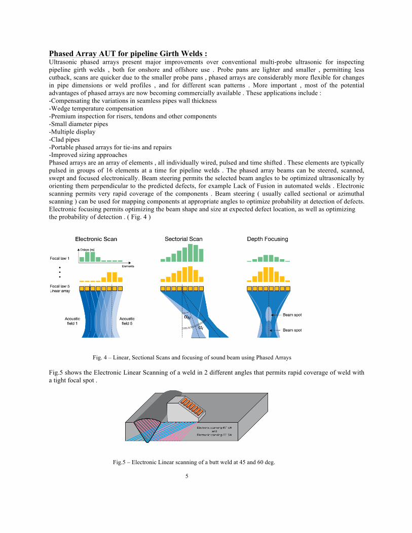
Phased Array AUT for pipeline Girth Welds : Ultrasonic phased arrays present major improvements over conventional multi-probe ultrasonic for inspecting pipeline girth welds , both for onshore and offshore use . Probe pans are lighter and smaller , permitting less cutback, scans are quicker due to the smaller probe pans , phased arrays are considerably more flexible for changes in pipe dimensions or weld profiles , and for different scan patterns . More important , most of the potential advantages of phased arrays are now becoming commercially available . These applications include : -Compensating the variations in seamless pipes wall thickness -Wedge temperature compensation -Premium inspection for risers, tendons and other components -Small diameter pipes -Multiple display -Clad pipes -Portable phased arrays for tie-ins and repairs -Improved sizing approaches Phased arrays are an array of elements , all individually wired, pulsed and time shifted . These elements are typically pulsed in groups of 16 elements at a time for pipeline welds . The phased array beams can be steered, scanned, swept and focused electronically. Beam steering permits the selected beam angles to be optimized ultrasonically by orienting them perpendicular to the predicted defects, for example Lack of Fusion in automated welds . Electronic scanning permits very rapid coverage of the components . Beam steering ( usually called sectional or azimuthal scanning ) can be used for mapping components at appropriate angles to optimize probability at detection of defects. Electronic focusing permits optimizing the beam shape and size at expected defect location, as well as optimizing the probability of detection . ( Fig. 4 )
Fig. 4 – Linear, Sectional Scans and focusing of sound beam using Phased Arrays Fig.5 shows the Electronic Linear Scanning of a weld in 2 different angles that permits rapid coverage of weld with a tight focal spot .
Fig.5 – Electronic Linear scanning of a butt weld at 45 and 60 deg. 5
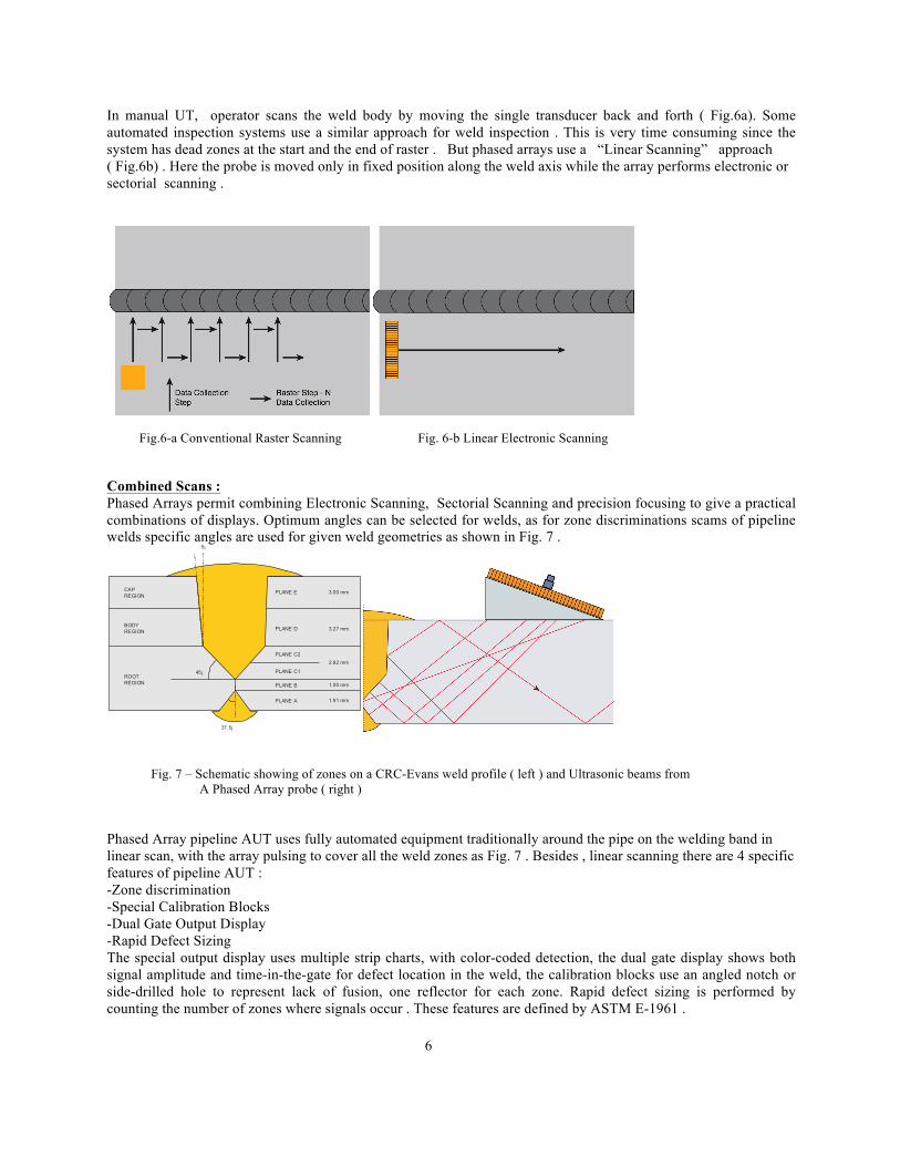
In manual UT, operator scans the weld body by moving the single transducer back and forth ( Fig.6a). Some automated inspection systems use a similar approach for weld inspection . This is very time consuming since the system has dead zones at the start and the end of raster . But phased arrays use a “Linear Scanning” approach ( Fig.6b) . Here the probe is moved only in fixed position along the weld axis while the array performs electronic or sectorial scanning .
Fig.6-a Conventional Raster Scanning Fig. 6-b Linear Electronic Scanning Combined Scans : Phased Arrays permit combining Electronic Scanning, Sectorial Scanning and precision focusing to give a practical combinations of displays. Optimum angles can be selected for welds, as for zone discriminations scams of pipeline welds specific angles are used for given weld geometries as shown in Fig. 7 .
Fig. 7 – Schematic showing of zones on a CRC-Evans weld profile ( left ) and Ultrasonic beams from A Phased Array probe ( right ) Phased Array pipeline AUT uses fully automated equipment traditionally around the pipe on the welding band in linear scan, with the array pulsing to cover all the weld zones as Fig. 7 . Besides , linear scanning there are 4 specific features of pipeline AUT : -Zone discrimination -Special Calibration Blocks -Dual Gate Output Display -Rapid Defect Sizing The special output display uses multiple strip charts, with color-coded detection, the dual gate display shows both signal amplitude and time-in-the-gate for defect location in the weld, the calibration blocks use an angled notch or side-drilled hole to represent lack of fusion, one reflector for each zone. Rapid defect sizing is performed by counting the number of zones where signals occur . These features are defined by ASTM E-1961 . 6
45¡
37.5¡
5¡
CAPREGION
PLANE E 3.00 mm
3.27 mm
2.82 mm
1.00 mm
1.91 mm
PLANE D
PLANE C2
PLANE C1
PLANE B
PLANE A
BODYREGION
ROOTREGION
Standardizing Concept: Until 1998 all mechanized UT on pipeline girth welds was done using Company Specifications specially worded to allow AUT . In 1993 TCPL ( TransCanada Pipeline Ltd. Introduced an inspection specification for mechanized girth welds that details the NDT required for total weld evaluation and acceptance criteria . In this specification evaluation was based on results of AUT and Visual inspection . RT was not requirement of this specification but could be used as a Quality Assurance check . This was required because all existing codes and standards were accepting only Manual UT . In 1998 ASTM E-1961 was published describing the various aspects involved in pipeline inspection using mechanized UT and zone discrimination . In 1999 in the 19th edition of API 1104 they revised its description of UT requirements to include mechanized systems . In Article 11.4.7.3 of API 1104 with title “Automated Ultrasonic Weld Testing” requirements of AUT have been detailed . It does not specify the zonal technique but if one is to use the alternative Acceptance Criteria in the Appendix of API 1104 there is no practical option other than the zonal technique . Most of the acceptance of the systems by pipeline industry has been dictated by presentation . In the same year Canadian Standard Association ( CSA ) included AUT in CSA Z662 that is the Canadian Standard for Oil and Gas Pipeline Systems . In year 2000 International standard ISO13847 “ Petroleum and Natural Gas industries – pipeline transportation systems – Welding of pipelines” was published as first time . Also Appendix E of DNV Offshore standard DNV-OS-F101 is titled with “Automated Ultrasonic Girth Weld Testing” . According to this standard : “Ultrasonic system may use pulse echo, tandem, TOFD or Through-Transmission techniques . It shall have a fully automatic recording system to indicate the location of defects and integrity of acoustic coupling . The system shall be configured such that the weld volume is divided into primary examination zones of a height not exceeding 3 mm.” It should be noted that sometimes the terms “ Code” , “Standard”, “Specification” and “Procedure” are confused in NDT . However, from technical point of view each refers to a separate type of document . “Standard”: is a written document assembled by recognized experts with the purpose of recommending actions to achieve certain objectives. A standard is usually enforced or given authority by an organization or agency typically professional societies or National standards. An example is ASNT recommended practice SNT-TC-1A that is American standard for qualification and certification of NDT personnel by employers . This standard has been accepted by American National Standard ( ANSI) , therefore it can be considered as a National standard . “Code” : When a standard is incorporated into law and hereby enforceable legally it is considered a “Code” . Examples of codes are : -ASME Boiler &Pressure Vessel Code -Canadian CSA Code Z226 “Oil & Gas pipeline Systems “ A federal agency may refer a standard and thereby give it “Code” status e.g 49CFR 192 is the American Pipeline Regulatory document and it references to API 1104 . Therefore API 1104 is basically a “Standard” but for pipeline industries in US it is an obligatory and a legal document ( Code ) . Specification” : is a specific document that is prepared by a user or purchaser for a specific product describing specific test procedure and acceptance criteria . “Specification” may refer to other codes and standards or require more stringent limits than the general standards . “Procedure” : is a written document for a specific project prepared by companies describing the all needs of a test method such as equipment , accessories , calibration , processing , periodic control, approved material, qualified personnel , acceptance criteria, repair , documenting and reporting . The procedure contains more details rather than the standards and specifications and helps to avoid the usual ambiguity of general standards. Most standards require “Procedure” signing between the purchaser and buyer before starting any inspection . “Technical Sheet”: is often a part of a procedure and provides a brief description of test application to specific part. There is another type of document that is used mainly by ASTM under title of “Guide” that is a compendium of information or series of options . This point must be considered in using ASTM documents as the title of volumes clearly indicates its nature. The well-known ASTM Annual Book 03.03 is a standard Guide and it may be used as recommended arbitrary Guide or obligatory standard when referenced by another code or standard . A careful look at wording in such Standard Guides indicates the prevalence of “should”(arbitrary) instead of “shall”(mandatory). Ultrasonic inspection generally can either be required by a standard or in turn may be regulated in some way by a standard . As an example ASME section VIII requires UT on a component and describes the acceptance criteria for the test method . This section of code doesn’t explain how to perform the inspection but refers to Section V to get the detail of set up , performance and the requirements of the test . Similarly in implementing AUT for pipeline girth welds , we would expect to have 2 sets of standards : 7
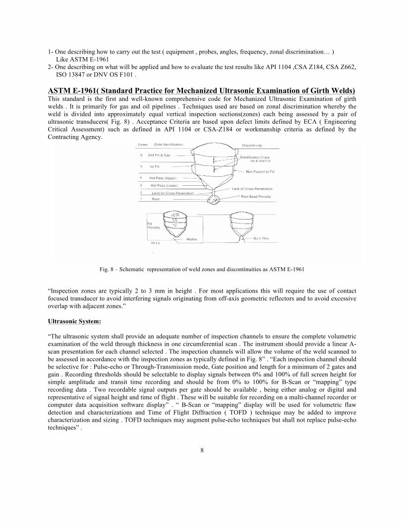
1- One describing how to carry out the test ( equipment , probes, angles, frequency, zonal discrimination… ) Like ASTM E-1961 2- One describing on what will be applied and how to evaluate the test results like API 1104 ,CSA Z184, CSA Z662, ISO 13847 or DNV OS F101 . ASTM E-1961( Standard Practice for Mechanized Ultrasonic Examination of Girth Welds) This standard is the first and well-known comprehensive code for Mechanized Ultrasonic Examination of girth welds . It is primarily for gas and oil pipelines . Techniques used are based on zonal discrimination whereby the weld is divided into approximately equal vertical inspection sections(zones) each being assessed by a pair of ultrasonic transducers( Fig. 8) . Acceptance Criteria are based upon defect limits defined by ECA ( Engineering Critical Assessment) such as defined in API 1104 or CSA-Z184 or workmanship criteria as defined by the Contracting Agency.
Fig. 8 – Schematic representation of weld zones and discontinuities as ASTM E-1961 “Inspection zones are typically 2 to 3 mm in height . For most applications this will require the use of contact focused transducer to avoid interfering signals originating from off-axis geometric reflectors and to avoid excessive overlap with adjacent zones.” Ultrasonic System: “The ultrasonic system shall provide an adequate number of inspection channels to ensure the complete volumetric examination of the weld through thickness in one circumferential scan . The instrument should provide a linear A-scan presentation for each channel selected . The inspection channels will allow the volume of the weld scanned to be assessed in accordance with the inspection zones as typically defined in Fig. 8” . “Each inspection channel should be selective for : Pulse-echo or Through-Transmission mode, Gate position and length for a minimum of 2 gates and gain . Recording thresholds should be selectable to display signals between 0% and 100% of full screen height for simple amplitude and transit time recording and should be from 0% to 100% for B-Scan or “mapping” type recording data . Two recordable signal outputs per gate should be available , being either analog or digital and representative of signal height and time of flight . These will be suitable for recording on a multi-channel recorder or computer data acquisition software display” . “ B-Scan or “mapping” display will be used for volumetric flaw detection and characterizations and Time of Flight Diffraction ( TOFD ) technique may be added to improve characterization and sizing . TOFD techniques may augment pulse-echo techniques but shall not replace pulse-echo techniques” .
8
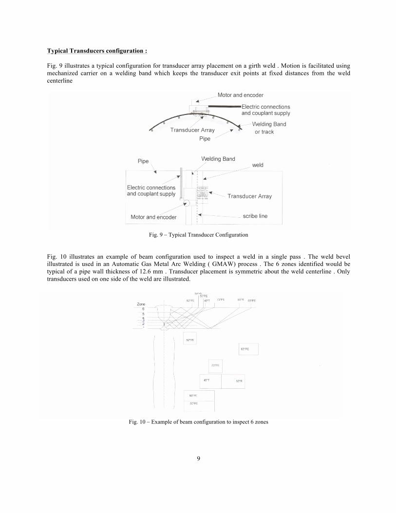
Typical Transducers configuration : Fig. 9 illustrates a typical configuration for transducer array placement on a girth weld . Motion is facilitated using mechanized carrier on a welding band which keeps the transducer exit points at fixed distances from the weld centerline
Fig. 9 – Typical Transducer Configuration
Fig. 10 illustrates an example of beam configuration used to inspect a weld in a single pass . The weld bevel illustrated is used in an Automatic Gas Metal Arc Welding ( GMAW) process . The 6 zones identified would be typical of a pipe wall thickness of 12.6 mm . Transducer placement is symmetric about the weld centerline . Only transducers used on one side of the weld are illustrated.
Fig. 10 – Example of beam configuration to inspect 6 zones
9
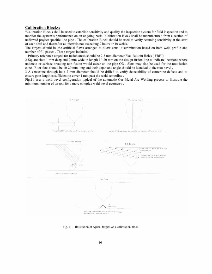
Calibration Blocks: “Calibration Blocks shall be used to establish sensitivity and qualify the inspection system for field inspection and to monitor the system’s performance on an ongoing basis . Calibration Block shall be manufactured from a section of unflawed project specific line pipe . The calibration Block should be used to verify scanning sensitivity at the start of each shift and thereafter at intervals not exceeding 2 hours or 10 welds.” The targets should be the artificial flaws arranged to allow zonal discrimination based on both weld profile and number of fill passes . These targets includes: 1-Primary reference targets for fusion areas should be 2-3 mm diameter Flat–Bottom Holes ( FBH ). 2-Square slots 1 mm deep and 2 mm wide in length 10-20 mm on the design fusion line to indicate locations where undercut or surface breaking non-fusion would occur on the pipe OD . Slots may also be used for the root fusion zone . Root slots should be 10-20 mm long and their depth and angle should be identical to the root bevel . 3-A centerline through hole 2 mm diameter should be drilled to verify detectability of centerline defects and to ensure gate length is sufficient to cover 1 mm past the weld centerline . Fig.11 uses a weld bevel configuration typical of the automatic Gas Metal Arc Welding process to illustrate the minimum number of targets for a more complex weld bevel geometry .
Fig. 11 - Illustration of typical targets on a calibration block 10

Fig.12 illustrates placement of holes and slots relative to the weld centerline for a 6 zoned weld similar to the configuration used in Fig.11 .
Fig. 12 – Illustration of target layout on calibration standard pipe section Standards of Acceptability : Standards of acceptability are to be established on the base of ECA ( Engineering Critical Assessment ) calculation that may be based on International codes like API 1104 , CSA –Z184 , CSA-Z662 , ISO 13847 or DNV- OS- F101 Examples of ECA determined Acceptance Criteria are shown in Tables 1 and 2 : 11

Table 1 Mechanized Girth Weld Acceptance Criteria ( based on Appendix K CSA-Z184 )
12
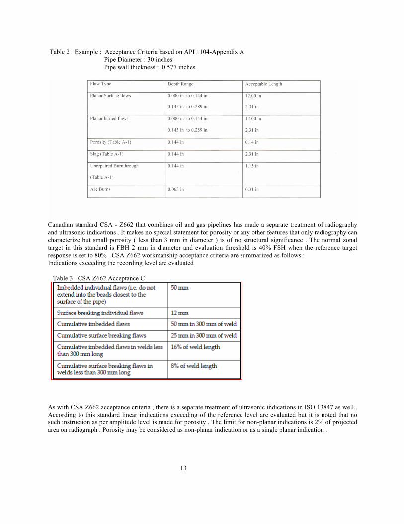
Table 2 Example : Acceptance Criteria based on API 1104-Appendix A Pipe Diameter : 30 inches Pipe wall thickness : 0.577 inches
Canadian standard CSA - Z662 that combines oil and gas pipelines has made a separate treatment of radiography and ultrasonic indications . It makes no special statement for porosity or any other features that only radiography can characterize but small porosity ( less than 3 mm in diameter ) is of no structural significance . The normal zonal target in this standard is FBH 2 mm in diameter and evaluation threshold is 40% FSH when the reference target response is set to 80% . CSA Z662 workmanship acceptance criteria are summarized as follows : Indications exceeding the recording level are evaluated Table 3 CSA Z662 Acceptance C
As with CSA Z662 acceptance criteria , there is a separate treatment of ultrasonic indications in ISO 13847 as well . According to this standard linear indications exceeding of the reference level are evaluated but it is noted that no such instruction as per amplitude level is made for porosity . The limit for non-planar indications is 2% of projected area on radiograph . Porosity may be considered as non-planar indication or as a single planar indication . 13
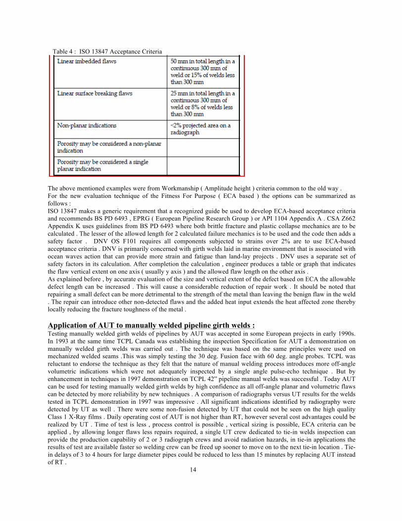
Table 4 : ISO 13847 Acceptance Criteria
The above mentioned examples were from Workmanship ( Amplitude height ) criteria common to the old way . For the new evaluation technique of the Fitness For Purpose ( ECA based ) the options can be summarized as follows : ISO 13847 makes a generic requirement that a recognized guide be used to develop ECA-based acceptance criteria and recommends BS PD 6493 , EPRG ( European Pipeline Research Group ) or API 1104 Appendix A . CSA Z662 Appendix K uses guidelines from BS PD 6493 where both brittle fracture and plastic collapse mechanics are to be calculated . The lesser of the allowed length for 2 calculated failure mechanics is to be used and the code then adds a safety factor . DNV OS F101 requires all components subjected to strains over 2% are to use ECA-based acceptance criteria . DNV is primarily concerned with girth welds laid in marine environment that is associated with ocean waves action that can provide more strain and fatigue than land-lay projects . DNV uses a separate set of safety factors in its calculation. After completion the calculation , engineer produces a table or graph that indicates the flaw vertical extent on one axis ( usually y axis ) and the allowed flaw length on the other axis . As explained before , by accurate evaluation of the size and vertical extent of the defect based on ECA the allowable defect length can be increased . This will cause a considerable reduction of repair work . It should be noted that repairing a small defect can be more detrimental to the strength of the metal than leaving the benign flaw in the weld . The repair can introduce other non-detected flaws and the added heat input extends the heat affected zone thereby locally reducing the fracture toughness of the metal . Application of AUT to manually welded pipeline girth welds : Testing manually welded girth welds of pipelines by AUT was accepted in some European projects in early 1990s. In 1993 at the same time TCPL Canada was establishing the inspection Specification for AUT a demonstration on manually welded girth welds was carried out . The technique was based on the same principles were used on mechanized welded seams .This was simply testing the 30 deg. Fusion face with 60 deg. angle probes. TCPL was reluctant to endorse the technique as they felt that the nature of manual welding process introduces more off-angle volumetric indications which were not adequately inspected by a single angle pulse-echo technique . But by enhancement in techniques in 1997 demonstration on TCPL 42” pipeline manual welds was successful . Today AUT can be used for testing manually welded girth welds by high confidence as all off-angle planar and volumetric flaws can be detected by more reliability by new techniques . A comparison of radiographs versus UT results for the welds tested in TCPL demonstration in 1997 was impressive . All significant indications identified by radiography were detected by UT as well . There were some non-fusion detected by UT that could not be seen on the high quality Class 1 X-Ray films . Daily operating cost of AUT is not higher than RT, however several cost advantages could be realized by UT . Time of test is less , process control is possible , vertical sizing is possible, ECA criteria can be applied , by allowing longer flaws less repairs required, a single UT crew dedicated to tie-in welds inspection can provide the production capability of 2 or 3 radiograph crews and avoid radiation hazards, in tie-in applications the results of test are available faster so welding crew can be freed up sooner to move on to the next tie-in location . Tie-in delays of 3 to 4 hours for large diameter pipes could be reduced to less than 15 minutes by replacing AUT instead of RT . 14
Influence of Material and Temperature ; Maintaining of zone discrimination is a critical aspect of the technique. Sound velocity variation causes significant zone changes of the beam . Variation of the sound velocity can be from 2 sources : Steel type and Temperature . Acoustic velocity variations from 3100 m/s to 3400 m/s were found to exist in the steels from various pipe mills . For this reason measuring the velocity of shear waves in each project is necessary and the procedure has been detailed in related standards like ASTM E-1961 . As well , the effect of temperature on Acoustic velocity of the Perspex refractory wedges is significant . In winter ambient temperature can drop to -50 deg. C , while the steel temperature after welding is around 40 deg. C . Winter projects require use of heated calibration blocks and 60% methyl alcohol in water is used a recycling couplant . Conclusion : For many years Radiography was the sole Non-Destructive Testing method for inspection of girth welds in pipeline construction that is accepted by all codes and standards. But since Radiography is slow process , has safety hazard problem and is poor to detect more critical planar defects ( cracks, lack of fusion, lack of penetration ) there was always trials to replace it by Ultrasonic Testing to overcome on these disadvantages . But for decades , the manual UT was the only possibility that was practical. Although manual UT has not any safety problem and is much better than radiography for planar defects but it is slow and the results are highly operator-dependent and less re-producible. The only solution to overcome on these disadvantages of manual UT was developing Automatic Ultrasonic Testing system and improving the probes function . After almost 3 decades efforts finally suitable AUT system equipped with focused probes were applied in projects in mid 1990s and today in many projects AUT is used instead of radiography . In the early years the application of AUT was based on company specification and by presentation of the system capabilities . It took long time that the pipeline standards accepted AUT for girth welds inspection . Since 10 years ago well-known pipeline standards like API 1104 , ISO 13847 , DNV-OS-F101 included AUT in the new versions . ASTM issued the guideline ASTM E-1961 in 1997 for this test . Other standards are currently working on topic. AUT is fast , more reliable and results are more reproducible . New UT technologies like Phased Array focused probes and TOFD technique are becoming more and more common and standardized in pipeline projects. Also advanced computer technology provided incredible facilities to obtain real UT pictures, storing and documentation of test results . Because of the demand of the pipeline industries , AWS has nominated a special committee to work on this topic as well that will be published in near future . References : 1- “Automated Ultrasonic Testing for Pipeline Girth Welds” E.A.Ginzel Olympus NDT 2- “Introduction to Phased Array Ultrasonic Technology Application” Olympus NDT 3- “Advances in Phased Array Ultrasonic Testing Technology Application” Olympus NDT 4- “Special Phased Array Application for Pipeline Girth Weld Inspection” Michael Moles , Fabio Fraga Moreira and Simon Labe 5-“Small diameter pipe girth weld inspection using Ultrasonic Phased Arrays “ Fabio Fraga Moreira and Michael Moles 6- Standard API 1104 “Welding of Pipelines and Related Facilities” 7- Standard ASTM 1961 “ Standard Practice for Mechanized Ultrasonic Examination of Girth Welds” 8- Standard DNV-OS-F101 “ Submarine Pipelines Systems” 9- Standard CSA-Z184 “Gas Pipelines Systems” 10-Standard CSA-Z662 “Oil & Gas Pipeline Systems” 11- Standard ISO 13847 “Petroleum and Natural gas Industries – Pipeline Transportation systems – Welding of pipelines” 12- Standard BS PD 6493 “Guidance on some methods for the derivation of acceptance levels from defects in fusion welded joints” 13- “Improved Focusing for Pipeline Girth Weld Inspection using Phased Arrays” M. Moles, S.Labbe and J.Zhang 14-“Application of Mechanized Ultrasonic Inspection to Manually Welded Pipeline Girth Welds” E.Ginzel, P.Den Boer, M. Hoff 15-“Pipeline AUT and Tolerances” Ed. Ginzel 16-“Code Review – TOFD and Pulse-echo Line Scanning” E.Ginzel, M.G.Lozev 17-“Further Developments in ultrasonic Inspection of Pipeline Girth Welds” E. Ginzel and M.Hoff 15